

Page 1
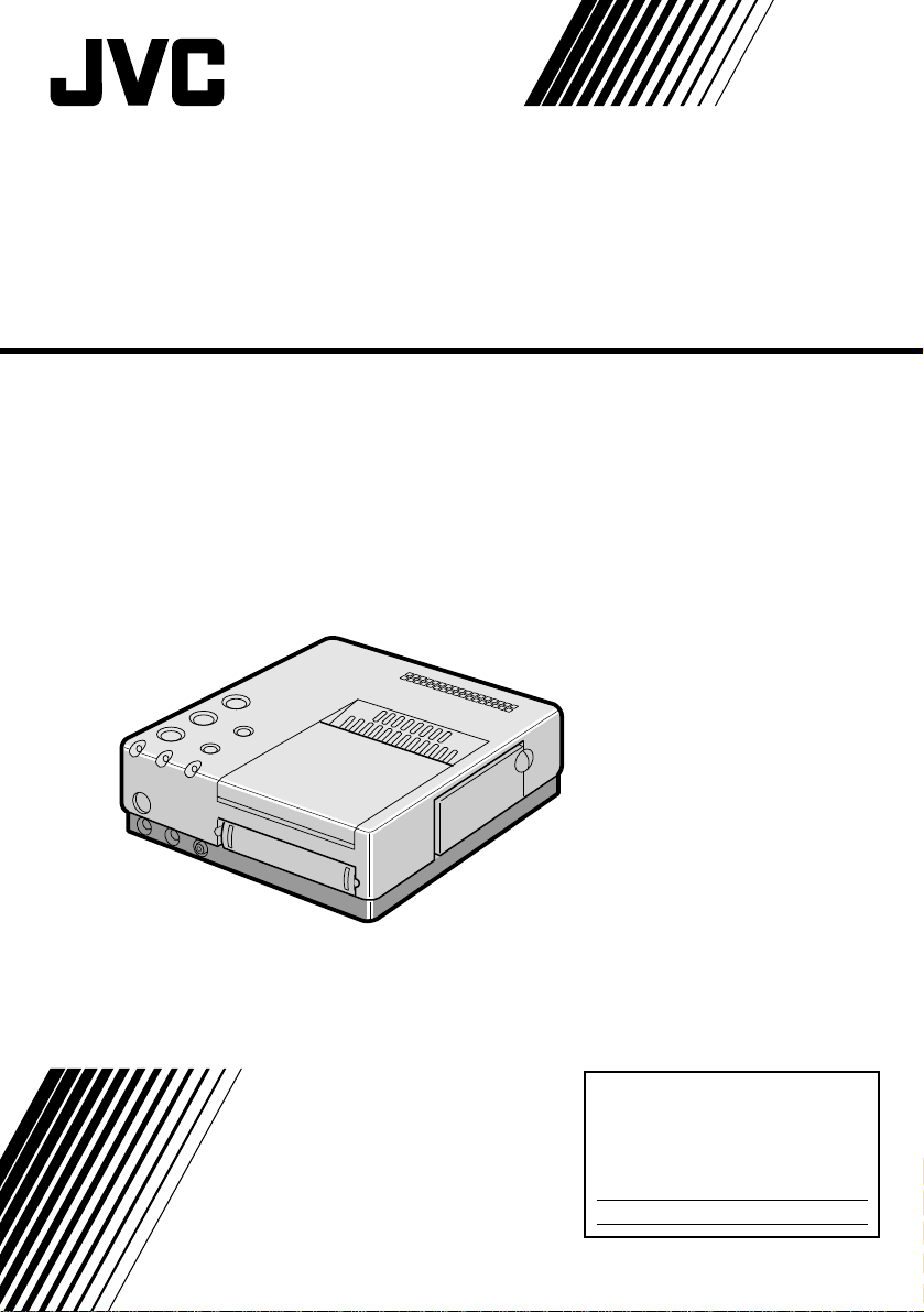
MULTIMEDIA PRINTER
GV-PT2
ENGLISH
INSTRUCTIONS
For Customer Use:
Enter below the Serial No. of the
GV-PT2U Multimedia Printer.
The serial number is located on the
bottom of the GV-PT2U.
Model No. GV-PT2U
Serial No.
LPT0002-023B
Page 2
2
Dear Customer,
Thank you for purchasing this Multimedia Printer.
Before use, please read the safety information
and precautions contained in the following pages
to ensure safe use of this product.
Using This Instruction Manual
•All major sections and subsections are listed in the
Table Of Contents (Z pg. 8, 9).
•Notes appear after most subsections. Be sure to
read these as well.
•Basic and advanced features/operation are
separated for easier reference.
It is recommended that you . . .
..... refer to “Controls, Indicators and Connectors”
(
Z pgs. 10 – 12) and familiarize yourself with
button locations, etc. before use.
..... read thoroughly the Safety Precautions and
Safety Instructions that follow. They contain
extremely important information regarding the
safe use of your new Multimedia Printer.
You are recommended to carefully read the
cautions on page 5 before use.
INFORMATION
This device complies with Part 15 of FCC Rules.
Operation is subject to the following two conditions:
(1) This device may not cause harmful interference, and
(2) this device must accept any interference received,
including interference that may cause undesired
operation. Change or modifications not approved by
the party responsible for compliance could void the
user’s authority to operate the equipment. This
equipment has been tested and found to comply with
the limits for a Class B digital device, pursuant to Part
15 of the FCC Rules. These limits are designed to
provide reasonable protection against harmful
interference in a residential installation. This equipment
generates, uses, and can radiate radio frequency energy
and, if not installed and used in accordance with the
instructions, may cause harmful interference to radio
communications. However, there is no guarantee that
interference will not occur in a particular installation.
If this equipment does cause harmful interference to
radio or television reception, which can be determined
by turning the equipment off and on, the user is
encouraged to try to correct the interference by one or
more of the following measures:
Reorient or relocate the receiving antenna.
Increase the separation between the equipment and
receiver.
Connect the equipment into an outlet on a circuit
different from that to which the receiver is connected.
Consult the dealer or an experienced radio/TV
technician for help.
SAFETY
PRECAUTIONS
CAUTION
RISK OF ELECTRIC SHOCK
DO NOT OPEN
CAUTION: TO REDUCE THE RISK OF ELECTRIC SHOCK.
DO NOT REMOVE COVER (OR BACK).
NO USER-SERVICEABLE PARTS INSIDE.
REFER SERVICING TO QUALIFIED SERVICE PERSONNEL.
The lightning flash with arrowhead symbol, within an
equilateral triangle, is intended to alert the user to the
presence of uninsulated "dangerous voltage" within the
product's enclosure that may be of sufficient magnitude
to constitute a risk of electric shock to persons.
The exclamation point within an equilateral triangle is
intended to alert the user to the presence of important
operating and maintenance (servicing) instructions in
the literature accompanying the appliance.
The GV-PT2 Multimedia Printer should be used with:
AC 120 V`, 60 Hz
To prevent electric shock and hazards, DO NOT use
any other power source.
CAUTION
TO PREVENT ELECTRIC SHOCK MATCH WIDE
BLADE OF PLUG TO WIDE SLOT, FULLY INSERT.
ATTENTION
POUR ÉVITER LES CHOCS ÉLECTRIQUES,
INTRODUIRE LA LAME LA PLUS LARGE DE LA FICHE
DANS LA BORNE CORRESPONDANTE DE LA PRISE
ET POUSSER JUSQU’AU FOND.
WARNING:
TO PREVENT FIRE OR SHOCK
HAZARD, DO NOT EXPOSE
THIS UNIT TO RAIN OR
MOISTURE.
NOTE:
The rating plate (serial number plate) and safety
caution are on the bottom and/or the back of the main
unit.
This Class B digital apparatus meets all requirements of
the Canadian Interference – Causing Equipment
Regulations.
“Cet appareil numérique de la classe B respecte toutes
les exigences du Règlement sur le matériel brouilleur
du Canada.”
Page 3

IMPORTANT PRODUCT
SAFETY INSTRUCTIONS
Electrical energy can perform many useful functions. But
improper use can result in potential electrical shock or fire
hazards. This product has been engineered and
manufactured to assure your personal safety. In order not to
defeat the built-in safeguards, observe the following basic
rules for its installation, use and servicing.
ATTENTION:
Follow and obey all warnings and instructions marked on
your product and its operating instructions. For your safety,
please read all the safety and operating instructions before
you operate this product and keep this manual for future
reference.
INSTALLATION
1. Grounding or Polarization
(A) Your product may be equipped with a polarized
alternating-current line plug (a plug having one blade
wider than the other). This plug will fit into the power
outlet only one way. This is a safety feature.
If you are unable to insert the plug fully into the outlet,
try reversing the plug. If the plug should still fail to fit,
contact your electrician to replace your obsolete
outlet. Do not defeat the safety purpose of the
polarized plug.
(B) Your product may be equipped with a 3-wire
grounding-type plug, a plug having a third (grounding)
pin. This plug will only fit into a grounding-type power
outlet. This is a safety feature.
If you are unable to insert the plug into the outlet,
contact your electrician to replace your obsolete
outlet. Do not defeat the safety purpose of the
grounding-type plug.
2. Power Sources
Operate your product only from the type of power source
indicated on the marking label. If you are not sure of the
type of power supply to your home, consult your product
dealer or local power company. If your product is intended
to operate from battery power, or other sources, refer to the
operating instructions.
3. Overloading
Do not overload wall outlets, extension cords, or integral
convenience receptacles as this can result in a risk of fire or
electric shock.
4. Power Cord Protection
Power supply cords should be routed so that they are not
likely to be walked on or pinched by items placed upon or
against them, paying particular attention to cords at plugs,
convenience receptacles, and the point where they exit
from the product.
3
5. Ventilation
Slots and openings in the cabinet are provided for
ventilation. To ensure reliable operation of the product and
to protect it from overheating, these openings must not be
blocked or covered.
• Do not block the openings by placing the product on a
bed, sofa, rug or other similar surface.
• Do not place the product in a built-in installation such as
a bookcase or rack unless proper ventilation is provided
or the manufacturer’s instructions have been adhered to.
6. Wall or Ceiling Mounting
The product should be mounted to a wall or ceiling only as
recommended by the manufacturer.
Page 4
4
USE
1. Accessories
To avoid personal injury:
• Do not place this product on an unstable cart, stand,
tripod, bracket or table. It may fall, causing serious injury
to a child or adult, and serious damage to the product.
• Use only with a cart, stand, tripod, bracket, or table
recommended by the manufacturer or sold with the
product.
• Use a mounting accessory recommended by the
manufacturer and follow the manufacturer’s instructions
for any mounting of the product.
• Do not try to roll a cart with small casters across
thresholds or deep-pile carpets.
2. Product and Cart Combination
A product and cart combination should be moved with
care. Quick stops, excessive force, and uneven surfaces
may cause the product and cart combination to overturn.
3. Water and Moisture
Do not use this product near
water—for example, near a bath
tub, wash bowl, kitchen sink or
laundry tub, in a wet basement, or
near a swimming pool and the
like.
4. Object and Liquid Entry
Never push objects of any kind into this product through
openings as they may touch dangerous voltage points or
short-out parts that could result in a fire or electric shock.
Never spill liquid of any kind on the product.
5. Attachments
Do not use attachments not recommended by the
manufacturer of this product as they may cause hazards.
6. Cleaning
Unplug this product from the wall outlet before cleaning.
Do not use liquid cleaners or aerosol cleaners. Use a damp
cloth for cleaning.
7. Heat
The product should be situated away from heat sources
such as radiators, heat registers, stoves, or other products
(including amplifiers) that produce heat.
PORTABLE CART WARNING
(Symbol provided by RETAC)
SERVICING
1. Servicing
If your product is not operating correctly or exhibits a
marked change in performance and you are unable to
restore normal operation by following the detailed
procedure in its operating instructions, do not attempt to
service it yourself as opening or removing covers may
expose you to dangerous voltage or other hazards. Refer all
servicing to qualified service personnel.
2. Damage Requiring Service
Unplug this product from the wall outlet and refer servicing
to qualified service personnel under the following
conditions:
a. When the power supply cord or plug is damaged.
b. If liquid has been spilled, or objects have fallen into the
product.
c. If the product has been exposed to rain or water.
d. If the product does not operate normally by following
the operating instructions. Adjust only those controls that
are covered by the operating instructions as an improper
adjustment of other controls may result in damage and
will often require extensive work by a qualified
technician to restore the product to its normal operation.
e. If the product has been dropped or damaged in any way.
f. When the product exhibits a distinct change in
performance—this indicates a need for service.
3. Replacement Parts
When replacement parts are required, be sure the service
technician has used replacement parts specified by the
manufacturer or have the same characteristics as the
original part. Unauthorized substitutions may result in fire,
electric shock or other hazards.
4. Safety Check
Upon completion of any service or repairs to this product,
ask the service technician to perform safety checks to
determine that the product is in safe operating condition.
Page 5
CAUTIONS
5
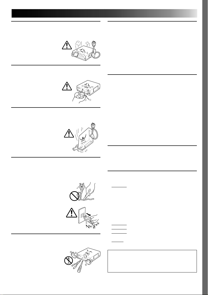
If you notice smoke or a peculiar smell coming from
the printer, shut it down and unplug it
IMMEDIATELY. Use of the printer under these
conditions could lead to fire
or electric shock. Contact
your JVC dealer. DO NOT
attempt to repair the
malfunction yourself.
DO NOT attempt to insert foreign objects into the
printer, as this can lead to electric shock or fire. If
an object other than print
paper is accidentally
inserted, shut the printer
down, unplug it and
contact your JVC dealer.
Exercise caution when moving the printer. If you
drop the unit, do not attempt to use it. If during use
you notice that the cabinet is
damaged, shut the printer
down, unplug it and contact
your JVC dealer. Use of the
printer under these
conditions can lead to fire or
electric shock.
DO NOT place heavy objects on the printer’s
power cord, or leave the cord near any heatgenerating appliance, as this can damage the cord.
Avoid excessive pulling or twisting of the power
cord. If the power cord
becomes cut or otherwise
damaged, contact your JVC
dealer. When unplugging the
printer, DO NOT pull on the
cord. Hold the plug itself and
remove it from the AC outlet.
Use of the printer with a
damaged power cord can
lead to fire, electric shock
and unit malfunctions.
DO NOT remove the cover and attempt to repair or
modify the printer. There are high-voltage
components within the unit,
and the risk of electric shock
and unit malfunctions exists.
If a problem occurs, contact
your JVC dealer.
ABOUT THERMAL HEADS
•The thermal heads, necessary for printing, are located
within the unit. The heads can become extremely
warm. To prevent possible burns and injuries, do not
touch the thermal heads.
•When the printer is used for extended periods, the
thermal heads experience wear and tear just like VCR
heads. As the thermal heads become worn, print
quality will gradually decrease. When you notice a
decline in quality, it is possible that the heads may
need to be replaced. Consult your JVC dealer.
MOISTURE CONDENSATION
If condensation occurs inside the printer, it may adhere
to print paper during printing, causing poor quality
prints and paper jams. If you think condensation may
exist within the unit, let the unit sit for at least 2 hours
(with the power on) to dry sufficiently. If paper is stuck
within the unit, remove it before turning the power on.
Unused print paper subjected to moisture should not
be used for printing.
•Condensation may occur in the following situations:
1) In a room when the heater suddenly comes on;
2) In the direct path of cool air from an air
conditioner;
3) When the unit is moved from a cool place to a
warm place.
DUST
Due to dust or lint adhering to print paper, or to
extreme variations in temperature, a small degree of
color smearing or lines may be visible in prints.
Failure to heed the following precautions may
result in damage to the printer.
1. DO NOT place the printer . . .
... in an environment prone to extreme temperatures
or humidity.
... in direct sunlight.
... in a dusty environment.
... in an environment where strong magnetic fields
are generated.
... on a surface that is unstable or subject to
vibration.
2.
DO NOT block the printer’s ventilation openings.
3.
DO NOT place heavy objects on the printer.
4.
DO NOT place anything which might spill on top of
the printer.
5.
AVOID violent shocks to the printer during
transport.
CAUTION:
Changes or modifications not approved by JVC
could void user’s authority to operate the
equipment.
Page 6
6
This printer allows you to print text or images on standard or seal paper in any of one of several
formats.
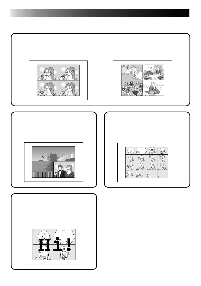
MAJOR FEATURES
A Variety of Special Effects Printing Options
MULTI-PRINT
Print 4 or 16 images on one sheet.
The same image ... (page 24) ... or different images (page 26)
INSET PRINT (page 28)
Inset one image inside another
TITLE IMPOSE PRINT
(page 42)
Impose hand-drawn titles or
illustrations on an image.
STROBE PRINT (page 30)
Print at set intervals, as when
taking snapshots in rapid
succession.
When using a JVC camcorder or
VCR ...
SNAPSHOT PRINT (page 46)
If your JVC camcorder is equipped with
Snapshot Search (such as the GR-SV7 or GRDV1), you can automatically edit and print
snapshots.
EDITING INDEX (page 48)
When used in conjunction with Random
Assemble Editing, this feature allows you to
create an index.
Page 7
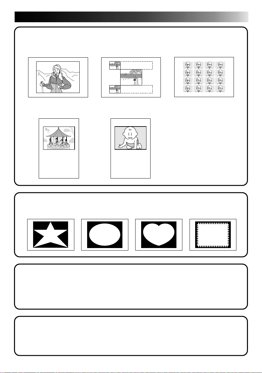
LAYOUT PRINT
Horizontal layout
(page 20)
Video cassette label
(page 34)
7
Name Sticker
(page 36)
Vertical layout
(page 32)
Calendar
(page 38)
JUN 1997
SUN
MON
TUE
1
2
3
8
9
10
15
16
17
22
23
24
29
30
WED
4
11
18
25
THU
FRI
SAT
5
6
7
12
13
14
19
20
21
26
27
28
MASKING PRINT (page 44)
STAR OVAL HEART WAVE
STORED TITLE IMPOSE (page 40)
•HAPPY BIRTHDAY •HAPPY HOLIDAYS
•CONGRATULATIONS •OUR VACATION
•WISH YOU WERE HERE
BUILT-IN CAPTURE FACILITY (page 63)
Images stored in the printer can be transferred to your computer.
The transferred image can be processed or printed using commercially available software.
Page 8

8
MAJOR FEATURES
CONTENTS
6
CONTROLS, INDICATORS AND CONNECTORS
Front View .................................................................................... 10
Rear View ..................................................................................... 11
Remote Control Unit ......................................................................... 12
PREPARATION OF THE REMOTE CONTROL (RC) UNIT
CONNECTIONS
INSTALLATION OF INK CASSETTE
LOADING THE PAPER TRAY
PREPARATION
BASIC PRINTING
DIFFERENT TYPES OF PRINTING
Print Menu Display........................................................................... 22
Setting (with remote control unit) ......................................................... 22
Select Layout.................................................................................. 23
Multi-Print (Same Scene).................................................................... 24
Multi-Print (Different Scenes) .............................................................. 26
Inset Print ..................................................................................... 28
Strobe Print ................................................................................... 30
Vertical Layout Print ......................................................................... 32
Video Cassette Label Print .................................................................. 34
Name Sticker Print ........................................................................... 36
Calendar Print................................................................................. 38
Stored Title Impose........................................................................... 40
Camera Title Impose ......................................................................... 42
Masking Print ................................................................................. 44
Snapshot Print ................................................................................ 46
Editing Index .................................................................................. 48
10
13
14
16
18
19
20
22
PERSONAL COMPUTER PRINTER SECTION
INTRODUCTION
51
52
Page 9
PERIPHERAL UNIT CONNECTIONS
9
54
INSTALLING THE SOFTWARE
OPEN & CLOSE (Basic Operation Procedure)
CONTROLS AND OPERATIONS
PRINTING PROCEDURE
Video Printer Operation ..................................................................... 63
PC Operation .................................................................................. 64
Print Operation ............................................................................... 64
How The Setup Dialog Works............................................................... 66
How The Spooler Window Works.......................................................... 67
TROUBLESHOOTING
SPECIFICATIONS
INDEX
56
58
60
63
68
74
75
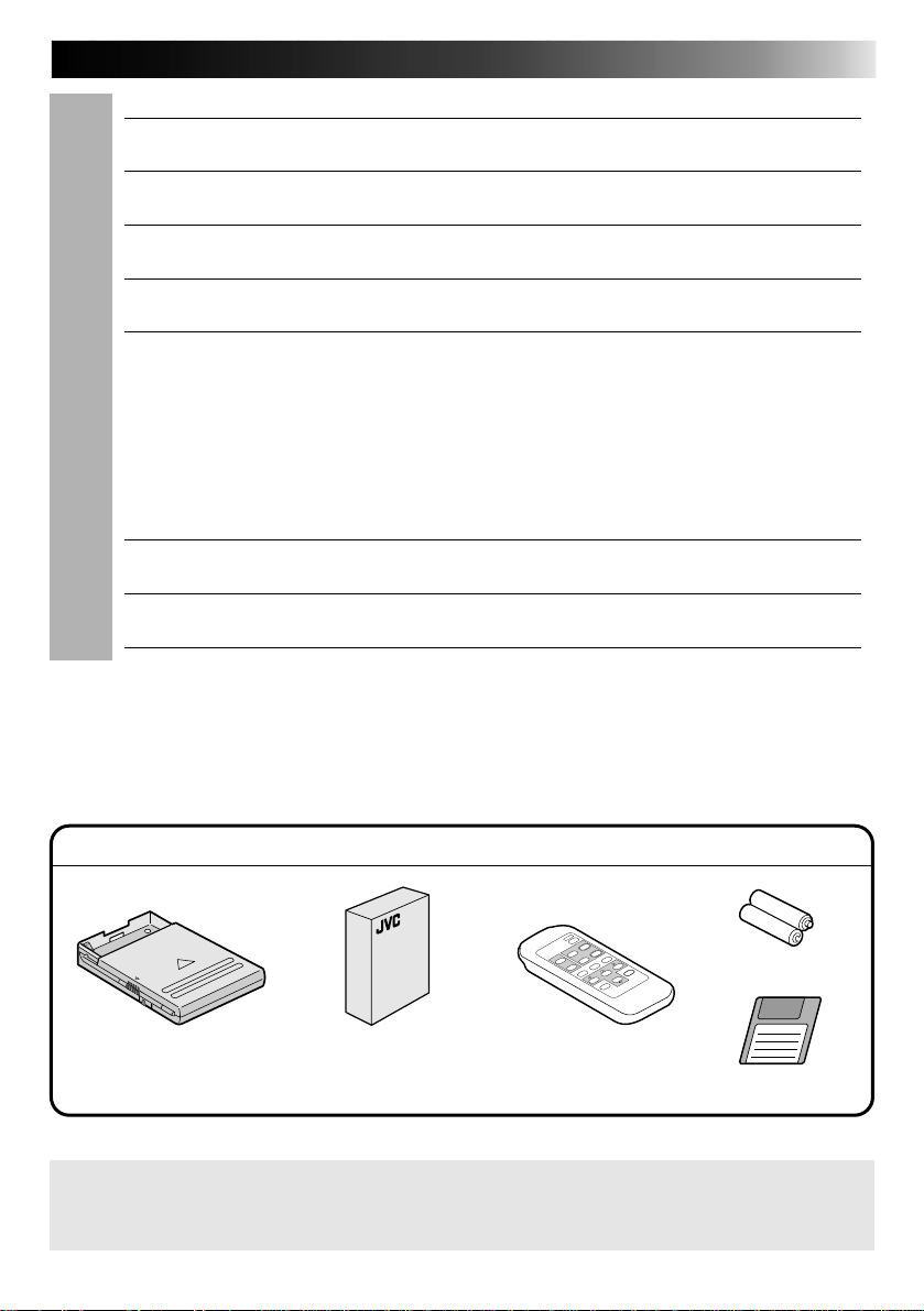
PROVIDED ACCESSORIES
“AAA” Battery x 2
Paper Tray
It should be noted that it my be unlawful to print from pre-recorded tapes or discs without
the consent of the owner of copyright in the video recording, broadcast or cable programme
and in any literary, dramatic, musical, or artistic work embodied therein.
Color Print Paper Sheet Set
•Standard Print Paper (10 sheets)
•Ink Cassette (10 prints)
Remote
Control Unit
Floppy Disk
Page 10
10
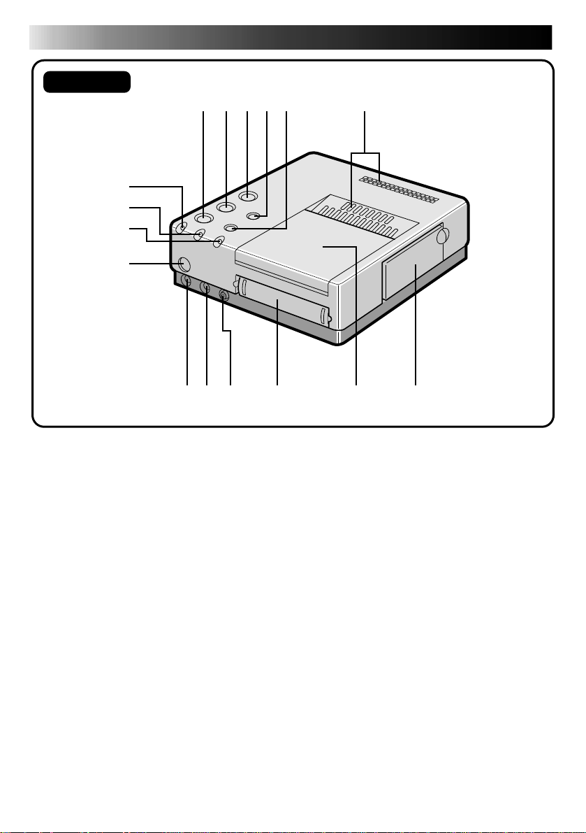
Front View
CONTROLS, INDICATORS AND CONNECTORS
7
8
9
0
1 2
345
6
!@ #
1
PRINT button
2 MEMORY button
• Press to store an input image for printing.
3 POWER button
• Turns the printer on and off.
4 SOURCE/ON LINE button
5 FRAME STABILIZER
6 Vent holes
• Periodically clean these holes with a
vacuum cleaner. Make sure the printer’s
power cord is unplugged.
7 ERROR lamp
8 INK lamp
• Lights when the ink cassette is loaded.
9 ON LINE lamp
• Lights when the PC mode is on.
0 Remote Control Signal Receiver
! REMOTE PAUSE connector
• Used when printing snapshots or an
editing index from a JVC camcorder or
video cassette recorder. Connect a
commercially available ø3.5mm mini
plug to either the camcorder’s editing
jack or the video cassette recorder’s
R.A.EDIT or SPECIAL FUNCTION jack.
$
%
@ S-Video Input Connector
• If the source unit has an S-Video output
jack, connect it to the multimedia printer
using a commercially available S-Video
cable. S-VHS input has priority over
normal inputs.
# Video Input Connector
• If the source unit doesn’t have an SVideo output jack, connect its normal
video output to the printer using a
commercially available video cable.
$ Paper Tray Insertion Slot
• Insert the paper tray into this slot.
% Output Tray
• Printed sheets are stacked here.
* Be sure to open the tray when using the
printer.
^ Ink Cassette Insertion Slot
• Open this to load or unload the ink
cassette.
^
Page 11
11
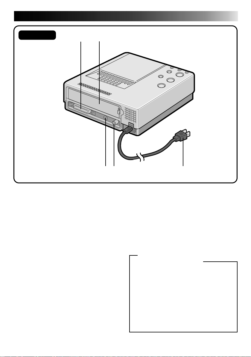
Rear View
&
*
()
& PARALLEL Connector
• Connect to the parallel (printer) terminal
of a computer using a commercially
available printer cable.
* Service Door for Jammed Paper Removal
• Open this door when paper is jammed.
* Do not open this door unless paper is
jammed. Be sure to close this after
clearing the paper jam.
( JLIP (Joint Level Interface Protocol)
Connector
• For connection to a computer for
manipulation of printer images. Refer to
the HELP or README files provided with
the HS-V1U (Ver 1.10) software for
details.
q
) Video Output Connector
• Use this connector when you want to
view the input image, or an image stored
in memory, on a television. Using a
commercially available video cable,
connect the printer to a television.
q Power Cord
• Plug into an AC outlet (AC 120 V).
Notice to JLIP PLAYER PACK HS-V1U
(Ver. 1.08) users
HS-V1U (Ver. 1.08) is not compatible with
the GV-PT2U. (If the version number is
not printed on the HS-V1U's diskette, that
means that the version is 1.08.)
A version of HS-V1U compatible with the
GV-PT2U will be made available from our
home page (in English):
<www> http://www.jvc-victor.co.jp/
For further details, consult your nearest
JVC dealer.
Page 12
12
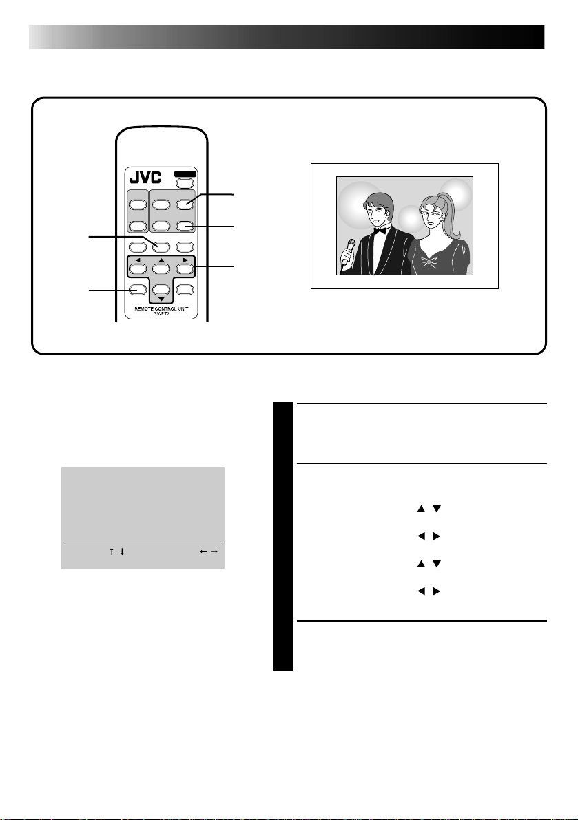
CONTROLS, INDICATORS AND CONNECTORS (cont.)
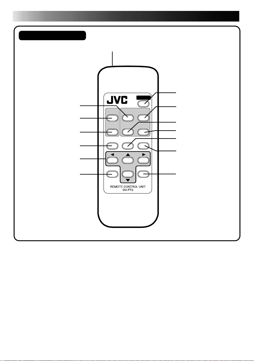
Remote Control Unit
1
2
3
4
5
6
7
1 Transmitter
2 SOURCE select button
3 TITLE button
4 MASKING button
5 MENU control button
6 CURSOR control button
7 OK button
TITLE
MASKING
MENU
OK
8
9
0
SOURCE
FRAME
STABILIZER
POWER
MEMORY
PRINT
!
FORMAT
MODE
@
#
CANCEL
$
8 POWER button
9 MEMORY button
0 FRAME STABILIZER
! PRINT button
@ FORMAT control button
# MODE select control button
$ CANCEL button
Page 13
PREPARATION OF THE REMOTE CONTROL (RC) UNIT
13
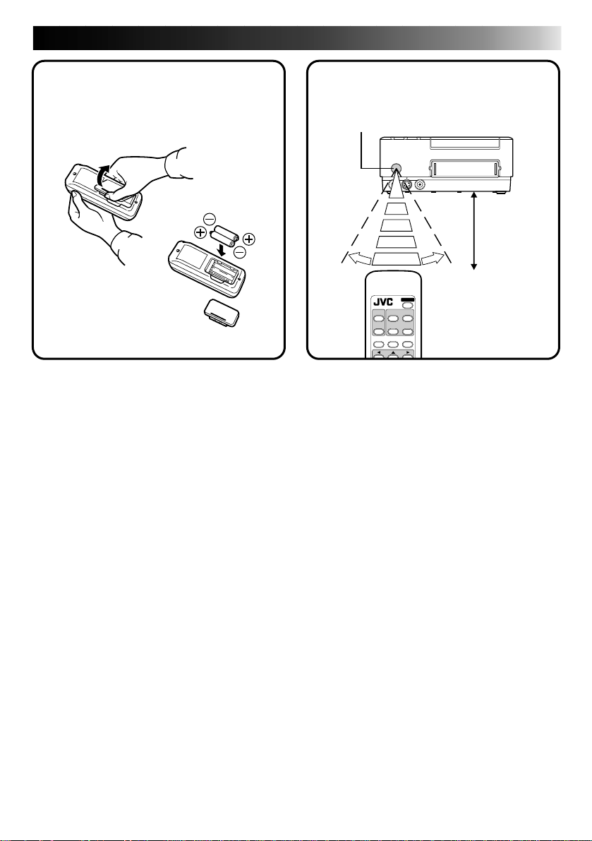
How to install the batteries
Place two R03/AAA batteries in the
compartment. Align the batteries as
shown.
Notes on the batteries
● Remove the batteries from the RC unit when
not using it for a long period.
● If the RC unit does not work properly,
remove the batteries from the unit and let it
stand for a while, then replace the batteries
and try using it again.
When to replace the batteries:
● When the remote control’s operating
distance starts to decrease, it means that the
battery level is dropping. In this case,
replace the batteries with new ones.
How to aim the remote control
unit
Remote control
signal receiver
Within 5 m
Approx.
30°
Operating distance
depends on the ambient
brightness and the angle
at which the RC unit is
aimed at the receiver.
When replacing the batteries
● Use two R03/AAA batteries.
● Replace both batteries at the same time. Do
not mix new batteries with used batteries.
● Insert the batteries in accordance with the +
and – indications.
● Be sure to read the precautions on the
battery label.
Page 14
14
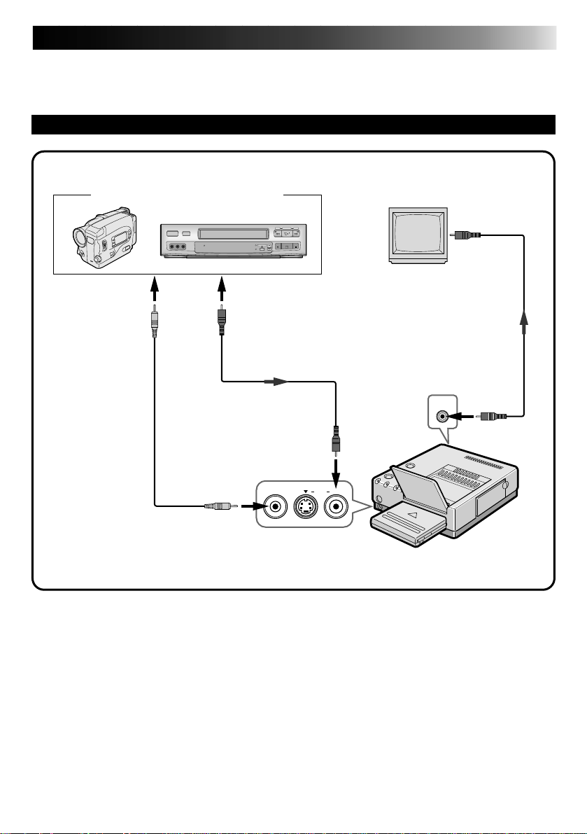
CONNECTIONS
Make sure that you have easy access to the AC outlet which the printer is plugged into so that it
can be immediately unplugged in case of emergency. Connect the printer power plug to a
different AC outlet from the TV and VCR.
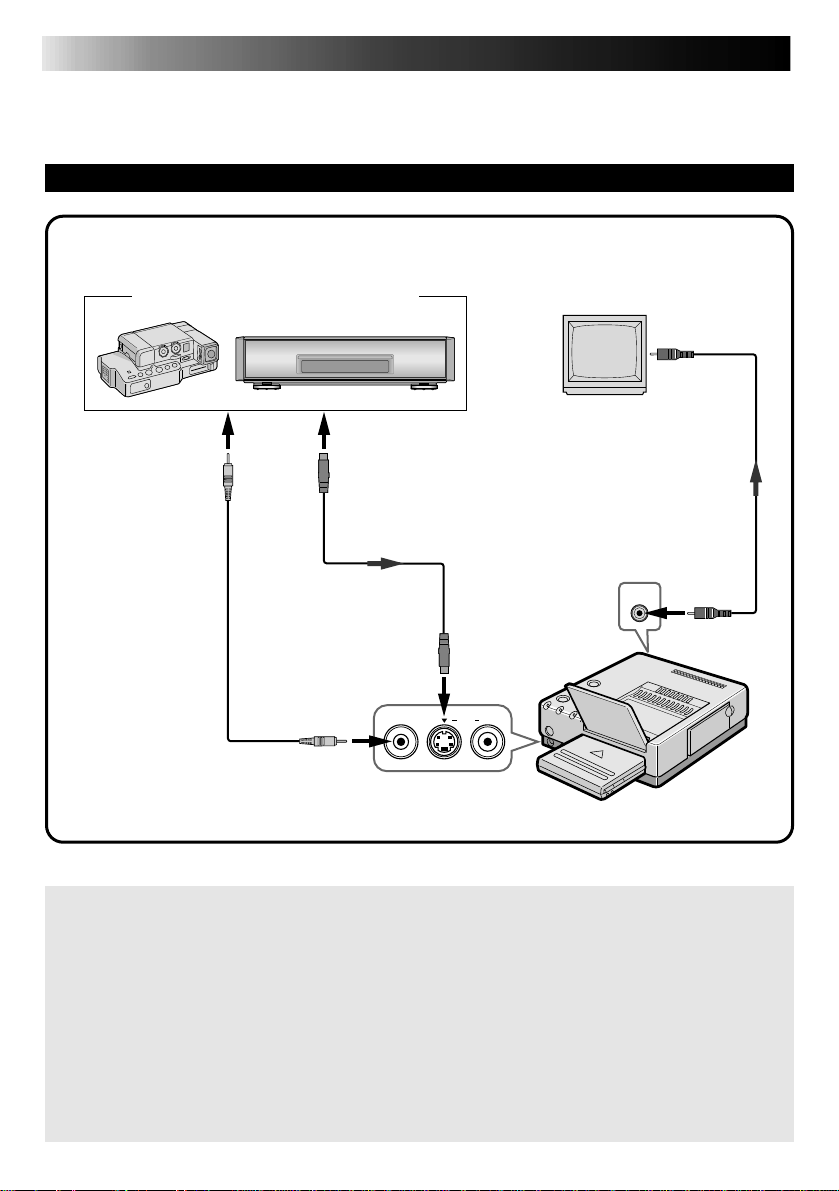
TO CONNECT TO AN IMAGE SOURCE WITH S-VIDEO OUTPUT CONNECTORS
Connection using S-video cable is recommended to ensure a clearer print.
Image source with S-Video output connectors
Connect to image
source S-Video
output connector
ø 3.5 mm Mini-Plug
cable (editing cable
optionally available
or provided with a
JVC camcorder)
Use this cable when using a JVC camcorder
equipped with an Editing connector, or a JVC
VCR equipped with an R.A. EDIT or SPECIAL
FUNCTION connector.
S-Video cable
(optional)
Connect to SVideo input
connector
REMOTE PAUSESINPUT
Front
connectors
Connect to
video input
connector
TV (set to VIDEO
(EXT. input) mode)
Video cable
(optional)
Rear connectors
VIDEO OUTPUT
Connect to video
output connector
VIDEO
Printer
Be sure to carefully review the instruction manuals for all the units that you will be using in conjunction with this printer.
Some televisions and video cassette recorders require a specific type of output cable. Refer to their
instruction manuals for details on television and VCR connections to the GV-PT2.
The printer assigns priority to input signals.
S-video signals take priority over regular video signals.
When you use an LCD video camera with a printer input connector:
When you connect the output of a camcorder equipped with an LCD monitor to the GV-PT2, you can
view the printer’s output image on the LCD monitor. Refer to the camcorder’s instruction manual for
connection details.
When SQUEEZE or CINEMA video is input into the S-Video input connector of the GV-PT2:
Print this input with a wide format (aspect ratio of 16 : 9)
Page 15
15
TO CONNECT TO AN IMAGE SOURCE WITH REGULAR VIDEO OUTPUT CONNECTORS
Image source with Video output connectors
Connect to image
source Video
output connector
ø 3.5 mm Mini-Plug
cable (editing cable
optionally available
or provided with a
JVC camcorder)
Use this cable when using a JVC camcorder
equipped with an Editing connector, or a JVC
VCR equipped with an R.A. EDIT or SPECIAL
FUNCTION connector.
Video cable
(optional)
REMOTE PAUSESINPUT
Front
connectors
Connect to
Video input
connector
VIDEO
Connect to
video input
connector
TV (set to VIDEO
(EXT. input) mode)
Video cable
(optional)
Rear connectors
VIDEO OUTPUT
Connect to video
output connector
Printer
Page 16
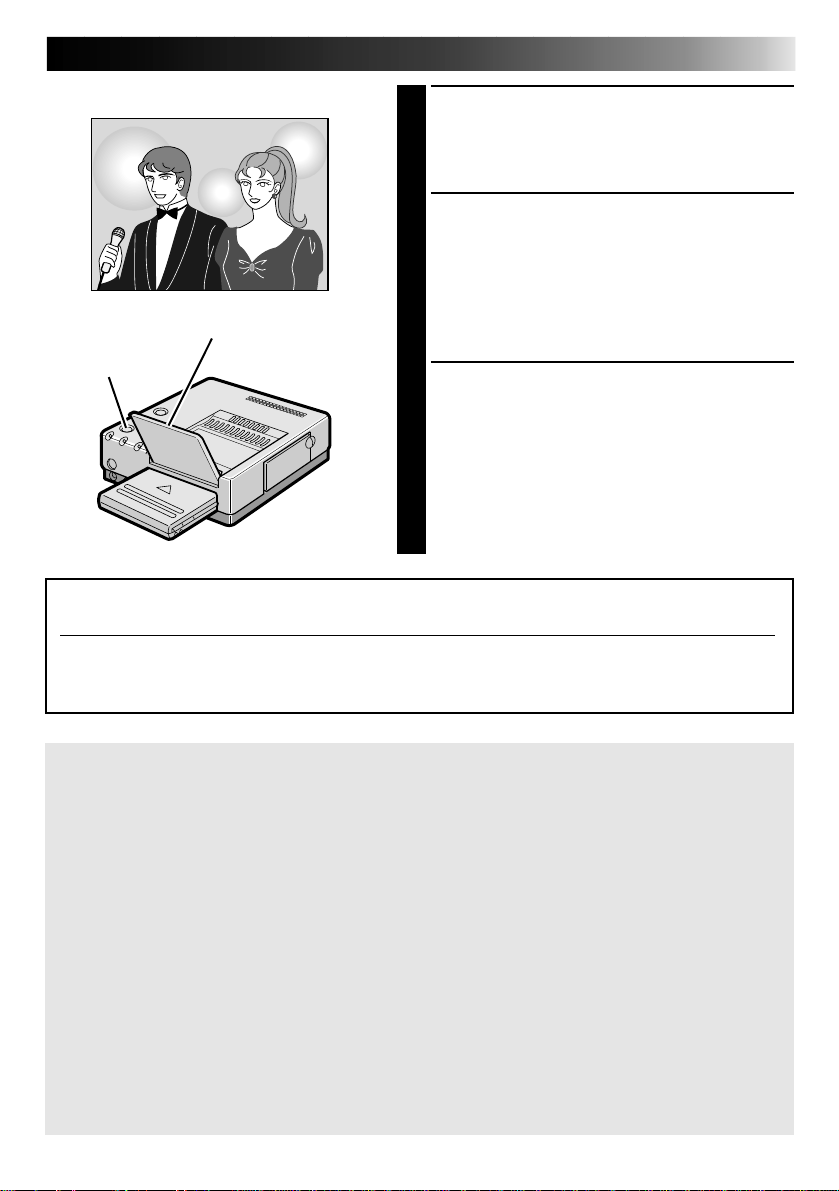
16
mark
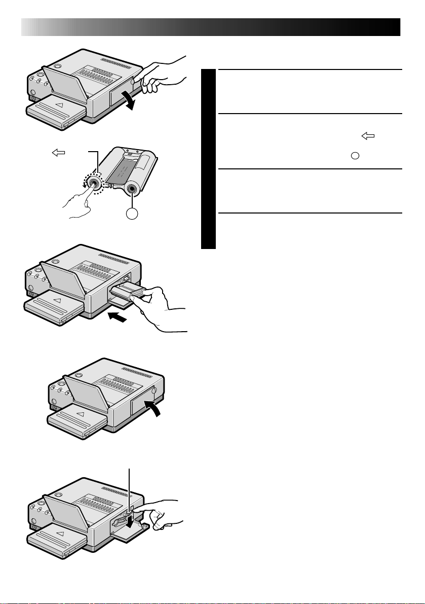
INSTALLATION OF INK CASSETTE
Install the ink cassette included with the optionally
available color print paper sheet set.
OPEN CASSETTE DOOR
1
Pull the right top of the door in the direction
indicated by the arrow to open it.
TAKE UP SLACK
2
Turn the roller on the side with the “ ” mark
in the direction of the arrow.
Do not turn the part marked with
INSTALL INK CASSETTE
3
Insert the cassette label-side up from the end
marked. Push it until you hear a click.
A
CLOSE CASSETTE DOOR
4
Push the right side of the door.
•The door clicks when it is fully closed.
A
.
Lock lever
When removing ink cassette
Push the lock lever in the direction of arrow.
The ink cassette is unlocked and can be removed.
CAUTION
Do not stick your fingers into the ink cassette
storage space. You may be burned or injured.
Page 17

About Color Print Paper Sheet Sets (optional)
You must use one of the sets shown in the following chart:
17
SET
PV-50SFAU
(Standard type)
PV-25SFSAU
(Sticker type)
Before Printing
● Do not touch printing side of the paper.
● Do not use paper that is torn or curled, as
this can result in paper jamming.
● Do not use paper that is wet or damp.
Printing may not be possible and paper
jamming may occur.
● Do not touch or pull out the ink cassette’s
ink sheet.
● Keep young children away from the ink
cassette’s ink sheet.
● When the ink cassette is empty, replace it
with a new one. An empty ink cassette
cannot be used. Do not try to rewind and
re-use cassette.
● Do not expose the paper to high temperatures, high humidity and/or direct sunlight.
● You can write on one side a PV-50SFAU
print sheet.
● If you want to write something or stick a
stamp on a PV-50SFAU sheet, wait until
printing is finished. If you write something
or stick something on before printing, the
printer may not work properly.
● Carefully read the precautions in the color
print paper sheet set box and on the back of
the color print paper sheet set before using.
• Standard Print Paper (50 Sheets)
• Ink Cassette (50 Prints)
• Sticker Print Paper (25 Sheets)
• Ink Cassette (25 Prints)
CONTENTS
USES
Print your favorite images, just like
snapshots.
Make customized seals and stick
them on greeting cards, envelopes,
letters, etc.
After Printing
● If you touch a fresh print with wet hands,
the print image may be discolored.
● If a print absorbs organic cleaning solvents
(alcohol, ester, keton, etc.), the colors will
fade.
● If cellophane tape or soft PVC are affixed to
a print, the chemical reaction will cause
accelerated color fading.
● When writing on a PV-50SFAU print sheet,
be sure to use a pencil or an oil-based
writing utensil. If you apply too much
pressure, you’ll leave imprints on the print
sheet.
Storage
● Avoid storing prints in areas subject to high
temperatures or humidity, or near a heater
or heat-generating device.
● Do not store prints in a soft plastic folder.
Accelerated color fading may result due to
the chemical reaction, or the print(s) may
stick to the file.
● Do not store 2 prints with the printed sides
touching, as the sheets may stick together.
● Store print paper in its box, on a level
surface. Failure to do so may cause the print
paper to curl or bend, which can result in a
paper jam within the unit.
Page 18
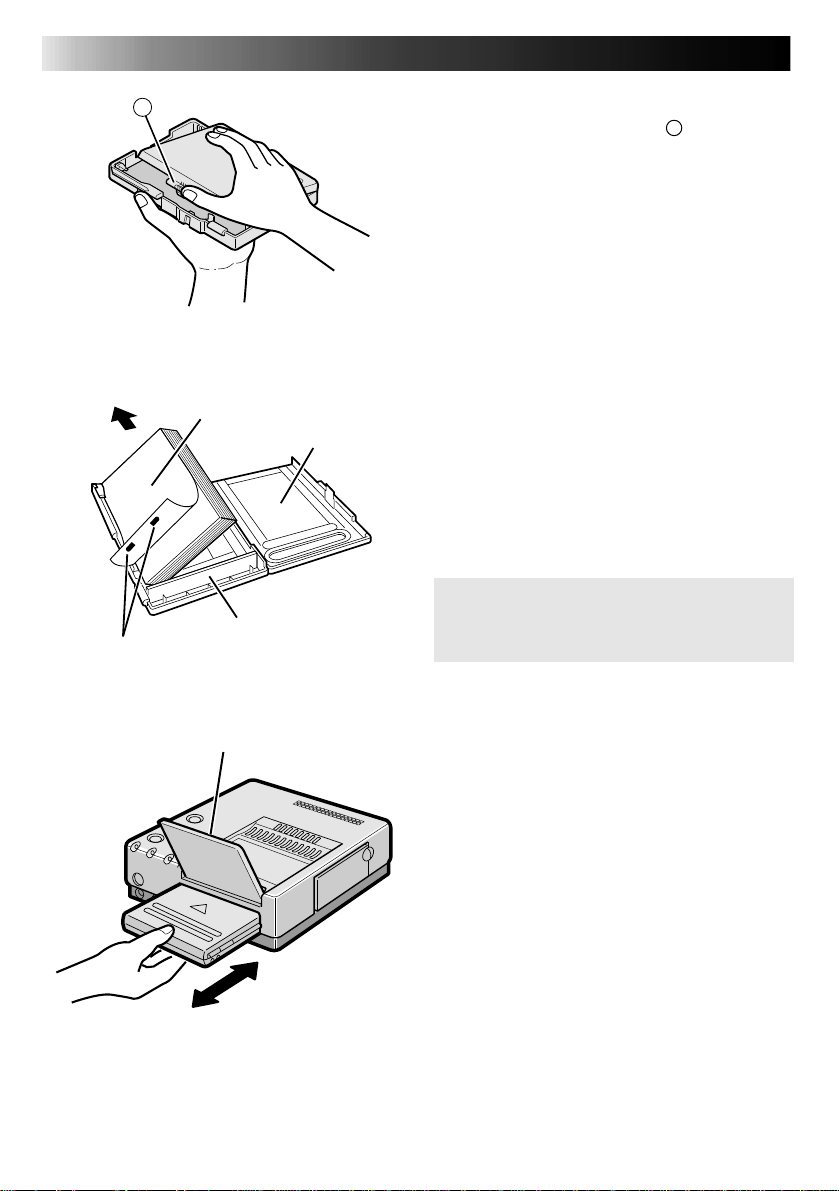
18
To printer
Detection marks
A
Printing side
Cautions
Partition panel
LOADING THE PAPER TRAY
Opening the paper tray
● Open the lid while pushing A.
Inserting color print paper sheets in
the paper tray
1. Keep the partition panel upright. If it is
tilted, get it upright by pushing the back of
the paper tray.
2. Load print sheets in the tray, placing the
side with the detection marks toward you,
face down.
•The tray can hold up to 25 sheets at one
time.
Be sure to read “Precautions when
inserting printing paper” on the back of
the paper tray lid.
Output tray
Loading/unloading the paper tray
● When loading, push the tray until it clicks.
● When unloading, push the tray slightly to
unlock the latch, then pull it out.
Page 19
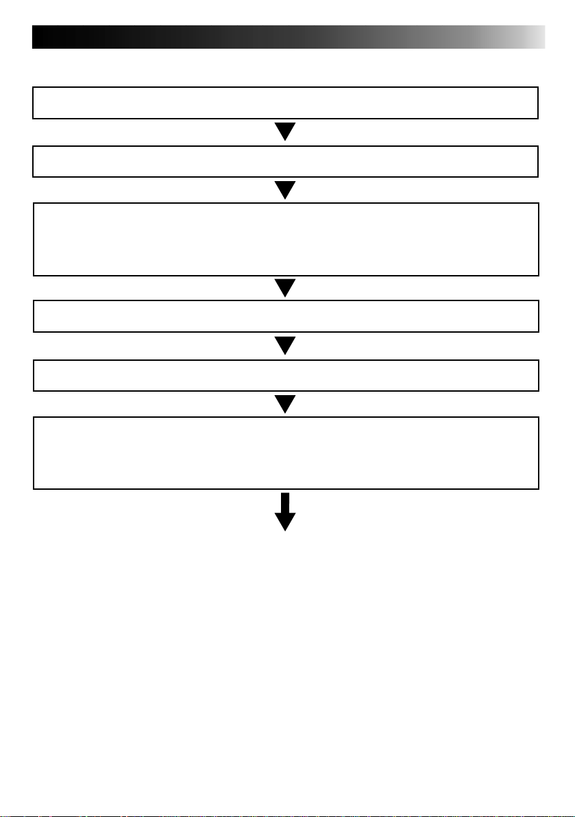
PREPARATION
● Before printing, make sure everything is set up and ready.
1
Have a Color Print Paper Sheet Set (option) ready. (page 17)
2
Install the ink cassette in the printer (page 16)
3
Place the color print paper sheets in the paper tray and load the
tray (page 18).
● Use print sheets and ink cassette from the same kit.
4
Open the output tray.
5
Connect image source to the printer (page 14).
6
Plug the printer’s power cable into an AC outlet and press the
POWER button.
● Power comes on and the POWER indicator lights.
19
You are now ready to print. For specific printing instructions,
read the page corresponding to the type of printing you
want to do (pages 20 through 49).
Page 20
20
This section explains how to print a single image — for example, if you want to print individual
photographs to put in a photo album.
POWER
SOURCE
1
TITLE
MASKING
MENU
FRAME
STABILIZER
FORMAT
MEMORY
PRINT
MODE
5
6
BASIC PRINTING
3
Preparation
See page 19.
FORMAT SELECT MENU
Z
LAYOUT: HORIZONTAL
MULTI: OFF
SELECT [/
]
OK [OK
OK
]
QUIT [FORMAT
CANCEL
SET [/]
2
PRESS FORMAT
1
•FORMAT SELECT MENU appears on the
connected monitor.
SELECT LAYOUT AND NO. OF
2
SCENES
1 Press cursor button / and place the
pointer
2 Press cursor button
]
3 Press cursor button
4 Press cursor button
PRESS OK
3
•FORMAT SELECT MENU disappears, and
setting is complete.
Z on LAYOUT.
and change the
LAYOUT to HORIZONTAL.
pointer
Z on MULTI.
number to OFF.
/
and place the
/
and change the
/
Page 21
21
BEGIN SOURCE PLAYBACK
4
Fast-forward or rewind the source tape to find
the desired scene, then start playback a little
before the scene.
PRESS MEMORY WHEN THE DE-
5
SIRED IMAGE APPEARS
•The image is stored in memory and appears
on the screen.
•If MEMORY display is unstable, press
Output tray
Print lamp
F.STABILIZER button to call up “F.STABILIZER
ON” on TV screen to stabilize the frame.
PRESS PRINT
6
•Print Lamp blinks, indicating that printing
has started.
•“Now printing!!” appears on screen during
printing.
•When the printed sheets are delivered to the
output tray and “Now printing!!” disappears,
printing is complete. Do not leave more
than 25 printed sheets stacked on the tray.
ATTENTION
When using the Video Printer GV-PT2 in a location where static electricity is easily produced
When you are printing more than one sheet consecutively, the GV-PT2 may stop printing
midway temporarily to avoid paper jam due to static electricity. When making more than one
print, make sure that over 5 printed sheets do not accumulate in the output tray.
If you want to switch between the input image and the stored image ...
press SOURCE. Each time you press the button, the displayed image alternates between the
input image and the stored image. This function is not available during printing.
If you store the wrong image or store an image incorrectly ...
press SOURCE to call up the INPUT display, then find the correct image and store it in
memory. The incorrect image will be deleted and the new image be stored.
FRAME STABILIZER
With a “squeezed” video input signal, switching between ON/OFF of FRAME STABILIZER is
not available. Enter the pause mode on the video unit, make sure that there is no noise or
fluctuation on the frame and store the scene in memory.
If you want to print multiple copies of the same scene ...
select the number of print copies on the PRINTER MENU screen. You can select up to 25
copies (page 22). When printing two or more copies, you can press the CANCEL button on
the remote control unit at any time to stop print operation after finishing the currently
printing page. “Remaining sheets: 1” appears on the monitor screen.
To print a “live” image using a camcorder as the source ...
in step
4
, instead of playing back the source tape, engage the camcorder’s Record mode.
Page 22
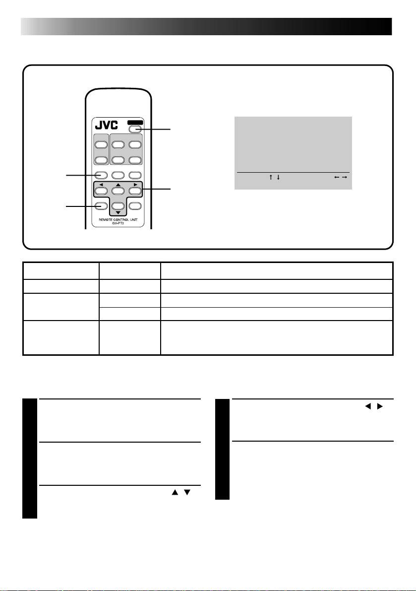
22
Print menu display
DIFFERENT TYPES OF PRINTING
2
TITLE
MASKING
MENU
OK
SOURCE
FRAME
STABILIZER
FORMAT
POWER
MEMORY
PRINT
MODE
CANCEL
1
3,4
PRINTER MENU
Z
NUMBER
OF PRINTS: 1
ON SCREEN: ON
I D NUMBER: 20
SELECT [/
OK [OK
PRINTER MENU display
]
]
SET [/]
QUIT [MENU
]
5
ITEM OPTIONS APPLICATION
No. of prints 1 – 25 Selectable up to 25. Factory set at 1.
ON SCREEN ON Usually set to ON.
OFF No display in the INPUT or MEMORY mode.
ID Number 1 – 99 Connection to and operation from a personal computer
Setting (with remote control unit)
PRESS POWER
1
•Power comes on and POWER indicator
lights.
will be possible using the JLIP connector.
Factory set at 20.
PRESS CURSOR BUTTONS
4
TO SELECT THE DESIRED OPTION
/
PRESS MENU
2
•PRINTER MENU appears on the
connected monitor.
PRESS CURSOR BUTTONS
3
TO PLACE THE POINTER Z ON
THE DESIRED ITEM
REPEAT 3 AND 4 AND PRESS
5
OK BUTTON WHEN SETTING IS
COMPLETE
/
•PRINTER MENU disappears and setting
is finished.
Page 23
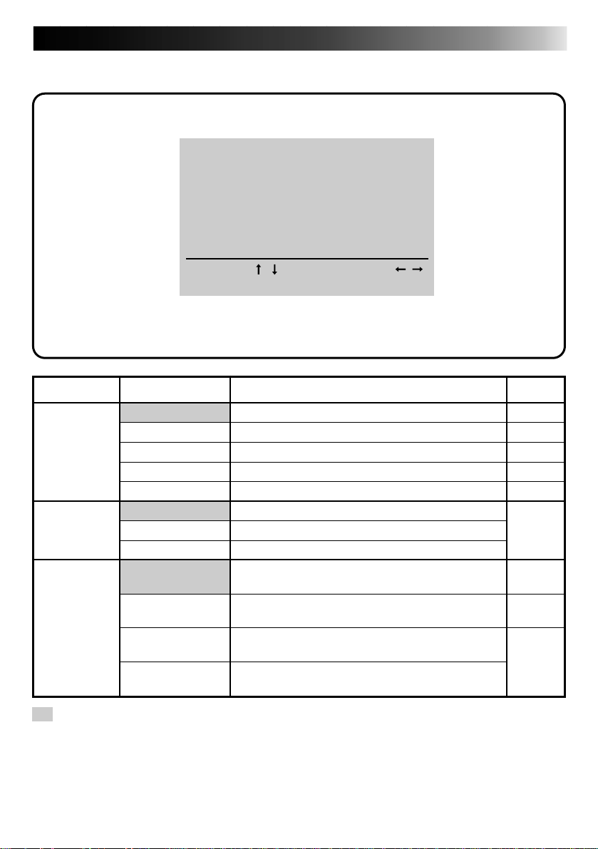
Select Layout
FORMAT SELECT MENU
LAYOUT: HORIZONTAL
Z
MULTI
:
4
CONTENT: SAME PIX
23
SELECT [/
OK [OK
ITEM OPTION
Layout HORIZONTAL
VERTICAL
VIDEO CASSETTE
NAME STICKER
CALENDAR
Number of
images
(displays only for
horizontal layout)
Image
content
(displays only
when number of
scenes is set to 4
or 16 in horizontal
layout)
OFF
4
16
SAME PIX
SELECTED PIX
STROBE <HIGH>
STROBE <LOW>
]
]
FORMAT SELECT MENU display
Usually set to this option.
For vertical layout.
To print video cassette labels.
To print stickers for visiting cards.
To print calendar on lower half of vertical layout.
To print 1 image.
To print 4 images on one sheet.
To print 16 images on one sheet.
Print the same image in each of the sections
(4/16) on one sheet.
Print selected images in each of the sections
(4/16) on one sheet.
Stores images at approximately 1/15 sec.
intervals when printing in Strobe Print format.
Stores images at approximately 1/2 sec.
intervals when printing in Strobe Print format.
QUIT [FORMAT
SET [/]
APPLICATION
]
Reference
page
24 – 31
32
34
36
38
24 – 31
24
26
30
: Factory setting. When you unplug the printer and plug it again, the default factory settings
are restored.
Page 24

24
DIFFERENT TYPES OF PRINTING (cont.)
Multi-Print (Same Scene)
You can print the same image 4 or 16 times on one sheet.
POWER
SOURCE
1
TITLE
MASKING
MENU
FRAME
STABILIZER
FORMAT
MEMORY
PRINT
MODE
5
6
3
Preparation
See page 19.
FORMAT SELECT MENU
LAYOUT: HORIZONTAL
Z
MULTI: 16
CONTENT: SAME PIX
SELECT [/
]
OK [OK
OK
]
QUIT [FORMAT
CANCEL
SET [/]
2
PRESS FORMAT
1
•FORMAT SELECT MENU appears on the
monitor.
SELECT HORIZONTAL ON LAYOUT,
2
SELECT 4 OR 16 ON MULTI AND
SELECT SAME PIX ON CONTENT
Press cursor buttons / to place the pointer
Z on items and press cursor buttons
]
change the options.
PRESS OK
3
•FORMAT SELECT MENU disappears and
selection is complete.
to
/
Page 25

Print lamp
Output tray
BEGIN SOURCE PLAYBACK
4
Fast-forward or rewind the source tape to find
the desired scene, then start playback a little
before the scene.
PRESS MEMORY WHEN THE DE-
5
SIRED IMAGE APPEARS
•The image is stored in memory and appears
on the screen.
•Only one image is stored in memory,
regardless of the MULTI setting.
•In order to superimpose titles and masking,
see pages 40 through 45. Title superimposing
or masking is done on each image.
PRESS PRINT
6
•Print Lamp blinks, indicating that printing
has started.
•“Now printing!!” appears on screen during
printing.
•When the printed sheets are delivered to the
output tray and “Now printing!!” disappears,
printing is complete. Do not leave more
than 25 printed sheets stacked on the tray.
25
FRAME STABILIZER
Switching between ON/OFF of FRAME STABILIZER is not available in Multi-Print (same
scene) mode.
Page 26

26
DIFFERENT TYPES OF PRINTING (cont.)
Multi-Print (Different Scenes)
You can print various images on the same print sheet.
POWER
SOURCE
6
1
TITLE
MASKING
MENU
FRAME
STABILIZER
FORMAT
MEMORY
PRINT
MODE
5
8
3
Preparation
See page 19.
FORMAT SELECT MENU
LAYOUT: HORIZONTAL
MULTI: 16
Z
CONTENT: SELECTED PIX
SELECT [/
]
OK [OK
OK
]
QUIT [FORMAT
CANCEL
SET [/]
2
PRESS FORMAT
1
•FORMAT SELECT MENU appears on the
monitor.
SELECT HORIZONTAL ON LAYOUT,
2
SELECT 4 OR 16 ON MULTI AND
SELECT SELECTED PIX ON CONTENT
Press cursor buttons / to place the pointer
Z on items and press cursor buttons
]
change the options.
PRESS OK
3
•FORMAT SELECT MENU disappears and
selection is complete.
to
/
Page 27

Image stored
Display of stored position
BEGIN SOURCE PLAYBACK
4
Fast-forward or rewind the source tape to find
the desired scene, then start playback a little
before the scene.
PRESS MEMORY WHEN THE DE-
5
SIRED IMAGE APPEARS
•The image is stored in memory and appears
in the upper lefthand corner of the screen.
•The next position to be stored in memory
appears in all white in the upper righthand
corner of the screen.
•You can select which position to store next
by pressing the cursor buttons
.
/
•With ON SCREEN set to OFF on the
PRINTER MENU (Page 22), only the position
stored in memory appears on the display.
PRESS SOURCE TO CALL UP THE
6
INPUT DISPLAY
REPEAT STEPS 5 AND 6 FOR EACH
7
IMAGE YOU ARE GOING TO PRINT
(4 OR 16) AND STORE THEM
•In order to superimpose titles and masking,
see pages 40 through 45. Title imposing or
masking is done across the entire screen, not
on each image separately.
/
27
and
PRESS PRINT
8
•Print Lamp blinks, indicating that printing
has started.
•“Now printing!!” appears on screen during
printing.
•When the printed sheets are delivered to the
output tray and “Now printing!!” disappears,
printing is complete. Do not leave more
than 25 printed sheets stacked on the tray.
FRAME STABILIZER
If MEMORY display is not stable, press F.STABILIZER button to call up “F.STABILIZER ON”
on TV screen.
If you store the wrong image or store an image incorrectly ...
1 Press the cursor buttons
● The position stored appears in white in the upper righthand corner of the screen.
2 Press SOURCE to call up the INPUT display and store a new image.
● The wrong image is deleted and the new image is stored in memory.
and / , and select the image you want to change.
/
Page 28

28
Inset Print
1,5
9
TITLE
MASKING
MENU
SOURCE
FRAME
STABILIZER
FORMAT
DIFFERENT TYPES OF PRINTING (cont.)
Main scene
POWER
MEMORY
PRINT
MODE
4,10
11
3,7
Preparation
See page 19.
FORMAT SELECT MENU
Z
LAYOUT: HORIZONTAL
MULTI: OFF
SELECT [/
]
OK [OK
OK
]
QUIT [FORMAT
CANCEL
SET [/]
2,6,8
]
Sub scene
Store the main scene
PRESS FORMAT
1
•FORMAT SELECT MENU appears on the
monitor.
SELECT HORIZONTAL ON LAYOUT
2
AND SELECT OFF FOR MULTI
Press cursor buttons / to place the pointer
Z on items and press cursor buttons
change the options.
PRESS OK
3
•FORMAT SELECT MENU disappears and
selection is complete.
BEGIN SOURCE PLAYBACK. WHEN
4
YOU REACH THE SCENE YOU
WANT TO SELECT AS THE MAIN
SCENE, PRESS MEMORY
•The main scene is stored and displayed on
the monitor.
to
/
Page 29

Store the sub scene
29
FORMAT SELECT MENU
LAYOUT: HORIZONTAL
MULTI: 4
Z
CONTENT: SELECTED PIX
SELECT [/
]
OK [OK
Position of the sub scene to
be stored displayed on screen
]
QUIT [FORMAT
SET [/]
PRESS FORMAT
5
•FORMAT SELECT MENU appears on the
monitor.
SELECT 4 OR 16 ON MULTI AND
6
SELECT SELECTED PIX ON CONTENT
]
Press cursor buttons / to place the pointer
Z on items and press cursor buttons
change the options.
•With 4 selected on MULTI, the size of the
sub scene will be 1/4 of the main scene area.
With 16 selected on MULTI, it will be 1/16 of
the main scene area.
to
/
PRESS OK
7
•FORMAT SELECT MENU disappears and
selection is complete.
SELECT THE POSITION WHERE THE
8
SUB SCENE IS STORED WITH CURSOR BUTTONS / AND
•The stored position of the sub scene is
displayed in white in the upper righthand
corner of the screen.
/
PRESS SOURCE BUTTON
9
•To call up the INPUT display.
WHEN THE IMAGE YOU WANT TO
10
SELECT AS A SUB SCENE IS
REACHED, PRESS MEMORY
•The sub scene inset in the main scene is
displayed on the monitor.
•If you want to inset more than one sub
scene, repeat steps
•In order to superimpose titles and masking,
see pages 40 through 45. Title imposing or
masking is done across the entire screen, not
on each image separately.
8
through 10.
FRAME STABILIZER
If MEMORY display is not stable,
press F.STABILIZER button to call up
“F.STABILIZER ON” on TV screen.
If you store the wrong main scene ....
redo the procedure from step
If you store the wrong sub scene ....
redo the procedure from step
1
.
8
to 10.
PRESS PRINT
11
•Print Lamp blinks, indicating that printing
has started.
•“Now printing!!” appears on screen during
printing.
•When the printed sheets are delivered to the
output tray and “Now printing!!” disappears,
printing is complete. Do not leave more
than 25 printed sheets stacked on the tray.
Page 30

30
DIFFERENT TYPES OF PRINTING (cont.)
Strobe Print
The printer stores a selected number of images at short intervals, and print them on one sheet.
POWER
SOURCE
1
TITLE
MASKING
MENU
FRAME
STABILIZER
FORMAT
MEMORY
PRINT
MODE
5
6
3
Preparation
See page 19.
FORMAT SELECT MENU
LAYOUT: HORIZONTAL
MULTI: 16
Z
CONTENT
SELECT [/
]
OK [OK
CANCEL
OK
:
STROBE<HIGH>
]
SET [/]
QUIT [FORMAT
2
PRESS FORMAT
1
•FORMAT SELECT MENU appears on the
monitor.
SELECT HORIZONTAL ON LAYOUT,
2
SELECT 4 OR 16 ON MULTI AND
SELECT STROBE<HIGH> OR
STROBE<LOW> ON CONTENT
Press cursor buttons / to place the pointer
]
change the options.
•The images are automatically stored at
intervals of approx. 1/15 sec. in
STROBE<HIGH> and 1/2 sec. in
STROBE<LOW>.
PRESS OK
3
•FORMAT SELECT MENU disappears and
selection is complete.
Z on items and press cursor buttons
to
/
Page 31

Print lamp
Output tray
BEGIN SOURCE PLAYBACK
4
Fast-forward or rewind the source tape to find
the desired scene, then start playback a little
before the scene.
PRESS MEMORY WHEN THE DE-
5
SIRED IMAGE APPEARS
•The images are automatically stored at
intervals of approx. 1/15 sec. in
STROBE<HIGH> and 1/2 sec. in
STROBE<LOW>.
•When the maximum number of images is
stored, the screen switches from INPUT to
MEMORY display.
•In order to superimpose titles, see pages 40
through 43. Title imposing is done across the
entire screen, not on each image separately.
•Masking facility is not available.
PRESS PRINT
6
•Print Lamp blinks, indicating that printing
has started.
•“Now printing!!” appears on screen during
printing.
•When the printed sheets are delivered to the
output tray and “Now printing!!” disappears,
printing is complete. Do not leave more
than 25 printed sheets stacked on the tray.
31
FRAME STABILIZER
Switching between ON/OFF of FRAME STABILIZER is not available in the Strobe Print mode.
Page 32

32
DIFFERENT TYPES OF PRINTING (cont.)
Vertical Layout Print
An image can be printed on the upper half of a print sheet.
POWER
SOURCE
1
TITLE
MASKING
MENU
FRAME
STABILIZER
FORMAT
MEMORY
PRINT
MODE
5
6
3
Preparation
See page 19.
FORMAT SELECT MENU
Z
LAYOUT: HORIZONTAL
MULTI: OFF
SELECT [/
]
OK [OK
FORMAT SELECT MENU
Z
LAYOUT: VERTICAL
SELECT [/
]
OK [OK
OK
]
QUIT [FORMAT
]
QUIT [FORMAT
CANCEL
SET [/]
SET [/]
2
PRESS FORMAT
1
•FORMAT SELECT MENU appears on the
monitor.
SELECT VERTICAL ON LAYOUT
2
]
]
Press cursor buttons / to choose the
options.
PRESS OK
3
•FORMAT SELECT MENU disappears and
selection is complete.
Page 33

33
Image on the TV monitor
The area within
the broken line is
stored in memory.
Image to be stored
BEGIN SOURCE PLAYBACK
4
Fast-forward or rewind the source tape to find
the desired scene, then start playback a little
before the scene.
PRESS MEMORY WHEN THE DE-
5
SIRED IMAGE APPEARS
•The desired image is stored in memory and a
vertical layout of the image appears on
screen.
•The area to be stored is as shown to the left.
•If the image was recorded with a camcorder,
the date display may be omitted from the
image.
•In order to print characters on lower half of
the layout, see the Camera Title Impose
section on page 42.
•Stored Title Impose or Masking is not
available in the Vertical Layout mode.
PRESS PRINT
6
•Print Lamp blinks, indicating that printing
has started.
•“Now printing!!” appears on screen during
printing.
•When the printed sheets are delivered to the
output tray and “Now printing!!” disappears,
printing is complete. Do not leave more
than 25 printed sheets stacked on the tray.
FRAME STABILIZER
Switching between ON/OFF of FRAME STABILIZER is not available in the Vertical Layout
mode.
Page 34

34
DIFFERENT TYPES OF PRINTING (cont.)
Video Cassette Label Print
You can print video cassette labels that you can use to record the contents of your video
cassettes. Use the optional Color Print Paper Sheet Set PV-25SFSAU.
Spine label
POWER
SOURCE
1
TITLE
MASKING
MENU
FRAME
STABILIZER
FORMAT
MEMORY
PRINT
MODE
5
6
3
Preparation
See page 19.
FORMAT SELECT MENU
Z
LAYOUT: HORIZONTAL
MULTI: OFF
SELECT [/
]
OK [OK
FORMAT SELECT MENU
Z
LAYOUT: VIDEO CASSETTE
SELECT [/
]
OK [OK
OK
]
QUIT [FORMAT
]
QUIT [FORMAT
CANCEL
SET [/]
SET [/]
2
PRESS FORMAT
1
FORMAT SELECT MENU appears on the
monitor.
SELECT VIDEO CASSETTE ON LAY-
2
]
]
OUT
Press cursor buttons / to choose the
options.
PRESS OK
3
•FORMAT SELECT MENU disappears and
selection is complete.
Page 35

BEGIN SOURCE PLAYBACK
4
Fast-forward or rewind the source tape to find
the desired scene, then start playback a little
before the scene.
PRESS MEMORY WHEN THE DE-
5
SIRED IMAGE APPEARS
•The desired scene is stored in memory and
appears on screen.
•While the MEMORY screen shows one
image, the actual print looks as illustrated on
the opposite page.
•In order to print characters on the spine label
of the cassette, see the Camera Title Impose
section on page 42.
•Stored Title Impose or Masking is not
available in this mode.
35
Output tray
Print lamp
FRAME STABILIZER
Switching between ON/OFF of FRAME STABILIZER is not available in the Video Cassette
Label Print mode.
To affix labels on video cassettes ...
First cut out the labels and then stick onto video cassettes.
PRESS PRINT
6
•Print Lamp blinks, indicating that printing
has started.
•“Now printing!!” appears on screen during
printing.
•When the printed sheets are delivered to the
output tray and “Now printing!!” disappears,
printing is complete. Do not leave more
than 25 printed sheets stacked on the tray.
Page 36

36
DIFFERENT TYPES OF PRINTING (cont.)
Name Sticker Print
You can print 16 separate copies of the same image. Use the optional Color Print Paper Sheet Set
PV-25SFSAU.
POWER
SOURCE
1
TITLE
MASKING
MENU
FRAME
STABILIZER
FORMAT
MEMORY
PRINT
MODE
5
6
3
Preparation
See page 19.
FORMAT SELECT MENU
Z
LAYOUT: HORIZONTAL
MULTI: OFF
SELECT [/
]
OK [OK
FORMAT SELECT MENU
Z
LAYOUT: NAME STICKER
SELECT [/
]
OK [OK
OK
]
QUIT [FORMAT
]
QUIT [FORMAT
CANCEL
SET [/]
SET [/]
2
PRESS FORMAT
1
•FORMAT SELECT MENU appears on the
monitor.
SELECT NAME STICKER ON LAYOUT
2
]
]
Press cursor buttons / to choose the
options.
PRESS OK
3
•FORMAT SELECT MENU disappears and
selection is complete.
Page 37

Print lamp
Output tray
BEGIN SOURCE PLAYBACK
4
Fast-forward or rewind the source tape to find
the desired scene, then start playback a little
before the scene.
PRESS MEMORY WHEN THE DE-
5
SIRED IMAGE APPEARS
•The desired image is stored in memory and
appears on screen.
•While the MEMORY screen shows one
image, the actual print looks as illustrated on
the opposite page.
•In order to superimpose title characters or
masking, see pages 40 through 45. Characters or masking are superimposed on each
copy of print.
PRESS PRINT
6
•Print Lamp blinks, indicating that printing
has started.
•“Now printing!!” appears on screen during
printing.
•When the printed sheets are delivered to the
output tray and “Now printing!!” disappears,
printing is complete. Do not leave more
than 25 printed sheets stacked on the tray.
37
FRAME STABILIZER
Switching between ON/OFF of FRAME STABILIZER is not available in the Name Sticker Print
mode.
Page 38

38
DIFFERENT TYPES OF PRINTING (cont.)
Calendar Print
You can print an image and calendar together. Available only with the vertical layout.
POWER
SOURCE
3
5,7
Preparation
See page 19.
TITLE
MASKING
MENU
OK
FRAME
STABILIZER
FORMAT
MEMORY
PRINT
MODE
CANCEL
2
8
4,6
CANCEL button
BEGIN SOURCE PLAYBACK
1
Fast-forward or rewind the source tape to find
the desired scene, then start playback a little
before the scene.
SUN
1
8
15
22
29
JUN 1997
MON
TUE
WED
THU
2
9
16
23
30
3
4
5
10
11
12
17
18
19
24
25
26
FRI
6
13
20
27
SAT
7
14
21
28
FORMAT SELECT MENU
Z
LAYOUT: CALENDAR
SELECT [/
]
OK [OK
]
QUIT [FORMAT
SET [/]
STORE THE DESIRED IMAGE IN
2
MEMORY
•The desired scene is stored in memory and
appears on screen.
•Select HORIZONTAL on LAYOUT and OFF
on MULTI for the print format of the image
you want to store. Other formats cannot be
correctly stored.
•Title Impose or masking is not available.
PRESS FORMAT
3
•FORMAT SELECT MENU appears on screen.
SELECT CALENDAR ON LAYOUT
4
Press cursor buttons / to choose the
]
options.
Page 39

39
MAKE/ERASE CALENDAR
Z
YEAR: 1997
MONTH: JUN
ERASE CALENDAR
SELECT [/
]
OK [OK
]
QUIT [FORMAT
SET [/]
]
MEMORY display on vertical
layout appears in the center of
screen together with this MAKE/
ERASE CALENDAR display
Image on the TV monitor
The area within
the broken line is
stored in memory.
Image to be stored
PRESS OK
5
•MAKE/ERASE CALENDAR display appears
with the image of vertical layout.
SET YEAR/MONTH OF CALENDAR
6
Press cursor buttons /, place the pointer Z
on year or month and change year or month
with cursor buttons
.
/
PRESS OK BUTTON
7
•Screen turns blue with “Please wait.”
displayed. After a while, the image combined with the calendar is displayed on
screen.
•Holidays are not colored red.
PRESS PRINT
8
•Print Lamp blinks, indicating that printing
has started.
•“Now printing!!” appears on screen during
printing.
•When the printed sheets are delivered to the
output tray and “Now printing!!” disappears,
printing is complete. Do not leave more
than 25 printed sheets stacked on the tray.
5 When you want to erase the calendar
before printing, press CANCEL. Pressing
the OK button restores the calender.
JUN 1997
SUN
MON
TUE
WED
THU
FRI
SAT
1
2
3
4
8
9
10
11
15
16
17
18
22
23
24
25
29
30
5
6
7
12
13
14
19
20
21
26
27
28
FRAME STABILIZER
Switching between ON/OFF of FRAME STABILIZER is not available in the Calendar Print
mode.
If you store the wrong calendar ...
redo steps
3
through 7.
Page 40

40
5
3
DIFFERENT TYPES OF PRINTING (cont.)
Stored Title Impose
Five different titles including “HAPPY BIRTHDAY” are stored in the printer and can be called up
for superimposed printing. Colors and positions of the titles are set in advance.
POWER
Congratulations
Congratulations
2
4
Preparation
See page 19.
TITLE
MASKING
MENU
OK
SOURCE
FRAME
STABILIZER
FORMAT
MEMORY
PRINT
MODE
CANCEL
CANCEL
button
SELECT/ERASE TITLE
Z
CONGRATULATIONS
ERASE TITLE
SELECT [/
OK [OK
]
]
SET [/]
QUIT [TITLE
STORE THE DESIRED IMAGE IN
1
MEMORY
See pages 20 through 31 for storing as desired.
PRESS TITLE
2
•SELECT/ERASE TITLE appears.
CHOOSE YOUR DESIRED TITLE
3
Press cursor buttons / to choose the title.
]
Page 41

Congratulations
Congratulations
41
PRESS OK
4
•Screen turns blue with “Please wait.”
displayed. The title superimposed on the
image then appears on MEMORY display.
•If masking is desired at the same time, follow
the steps
•When both the masking and title are superimposed on the image, the title appears on
the frame.
2
through 4 on page 44.
PRESS PRINT
5
•Print Lamp blinks, indicating that printing
has started.
•“Now printing!!” appears on screen during
printing.
•When the printed sheets are delivered to the
output tray and “Now printing!!” disappears,
printing is complete. Do not leave more
than 25 printed sheets stacked on the tray.
5 When you want to erase the title before
printing, press CANCEL. Pressing the OK
button restores the title.
5 If you want to erase title only when
superimposing both title and masking ...
1. Press TITLE.
•SELECT/ERASE TITLE appears.
2. Press cursor buttons
pointer Z on ERASE TITLE.
3. Press OK.
•The title and the SELECT TITLE/ERASE
disappear.
•See page 45 to erase masking only.
and place the
/
If the title characters and on-screen display are superimposed upon one another, making
the MEMORY display difficult to view ...
1. Press MENU.
PRINTER MENU appears.
2. Press cursor buttons
3. Press cursor buttons
4. Press OK.
PRINTER MENU disappears with no message displayed on screen.
If you want to change the title ...
redo the steps
2
through 4.
and place the pointer Z on ON SCREEN.
/
and to choose OFF.
/
Page 42

42
7
DIFFERENT TYPES OF PRINTING (cont.)
Camera Title Impose
You can print a scene or image with your own handwritten characters or drawing imposed on it.
The title or drawing will cover the entire image area of the color print paper sheet, regardless of
the “MULTI” setting.
Horizontal Layout Format
Vertical Layout
Format
POWER
SOURCE
3
TITLE
MASKING
MENU
FRAME
STABILIZER
FORMAT
MEMORY
PRINT
MODE
9
Video Cassette Label Format
5,6,8
Preparation
See page 19.
SELECT/ERASE TITLE
Z
HAPPY BIRTHDAY
ERASE TITLE
SELECT [/
]
OK [OK
]
OK
SET [/]
QUIT [TITLE
CANCEL
]
4,
STORE THE DESIRED IMAGE IN
1
MEMORY
See pages 20 through 35 for storing as desired.
RECORD TITLE OR DRAWING WITH
2
YOUR CAMCORDER
Connect the S-Video (or Video) output
connector of the camcorder to the S-Video (or
Video) input connector and record your title or
drawing using the camcorder.
•To ensure that your title or drawing is clearly
visible and contrasts sufficiently with the
image, use a dark-colored pen, pencil or
marker on white or light-colored paper.
Make sure the lines are wide and the figures
large.
PRESS TITLE
3
•SELECT/ERASE TITLE appears.
Page 43

43
SELECT/ERASE TITLE
Z
CAMERA TITLE
ERASE TITLE
SELECT [/
OK [OK
Z
Z
COLOR
COLOR
INVERSE:NO
INVERSE:NO
SELECT [/
SELECT [/
OK [OK
OK [OK
]
]
SET CAMERA TITLE
SET CAMERA TITLE
]
]
:
:
]
]
BLACK
BLACK
SET [/]
QUIT [TITLE
SET [/]
SET [/]
QUIT [TITLE
QUIT [TITLE
SELECT CAMERA TITLE
4
Press cursor buttons / to place the pointer
Z on CAMERA TITLE.
PRESS OK
5
]
•SELECT/ERASE TITLE disappears with title
entry display entered.
•Title automatically turns blue.
•If a vertical layout or video cassette label
format is selected, ensure that the title is
inside the image area.
•With vertical layout, the title will be set in
the lower half of the image stored.
•With video cassette label, the same title is set
on two spine labels.
WHEN THE TITLE OR DRAWING TO
6
BE PRINTED HAS BEEN CHOSEN,
PRESS OK
•SET CAMERA TITLE appears.
•Title automatically turns black.
]
]
CHOOSE NEGATIVE/POSITIVE OF
7
THE TITLE
1 Press cursor buttons / and choose the
color.
BLACK
BLUE
WHITE
GREEN
2 Press cursor buttons
pointer Z on INVERSE.
3 Press cursor buttons
or NO.
YELLOW
LIGHT BLUE
and place the
/
and choose YES
/
PINK
RED
Erase title when printing is finished.
1 Press TITLE.
•SELECT/ERASE TITLE appears.
2 Press cursor buttons
the pointer Z on ERASE TITLE.
3 Press OK.
•The title disappears.
If you want to change the title ...
after performing steps 1 through 2,
redo steps
2
through 8.
If you want to change COLOR or
INVERSE ...
redo steps
3, 4, 5, 7, 8
and place
/
.
PRESS OK
8
•Screen turns blue with “Please wait.”
displayed. The title superimposed on the
image then appears and is stored in memory.
•With video cassette label, the title is superimposed on the image stored, though actual
print looks like illustrated on page 42.
PRESS PRINT
9
•Print Lamp blinks, indicating that printing
has started.
•“Now printing!!” appears on screen during
printing.
•When the printed sheets are delivered to the
output tray and “Now printing!!” disappears,
printing is complete. Do not leave more
than 25 printed sheets stacked on the tray.
Page 44

44
5
DIFFERENT TYPES OF PRINTING (cont.)
Masking Print
You can print an image inside a frame by masking part of the image. Four different frame
shapes are available.
Star Oval Heart Wave
POWER
SOURCE
2
TITLE
MASKING
MENU
FRAME
STABILIZER
FORMAT
MEMORY
PRINT
MODE
3
4
Preparation
See page 19.
SELECT/ERASE MASKING
Z
SHAPE
COLOR
ERASE MASKING
SELECT [/
]
OK [OK
OK
:
STAR
:
BLACK
]
QUIT [MASKING
CANCEL
SET [/]
]
CANCEL
button
STORE THE DESIRED IMAGE IN
1
MEMORY
See pages 20 through 29.
PRESS MASKING
2
•SELECT/ERASE MASKING appears.
CHOOSE COLOR AND SHAPE OF
3
MASK
1 Press cursor buttons / and place the
pointer Z on SHAPE.
2 Press cursor buttons
shape.
STAR
OVAL
3 Press cursor buttons
pointer Z on COLOR.
4 Press cursor buttons
BLACK
BLUE
WHITE
GREEN
and choose
/
HEART
and place the
/
and choose color.
/
YELLOW
LIGHT BLUE
WAVE
PINK
RED
Page 45

PRESS OK
4
•Screen turns blue with “Please wait.”
displayed. The masking superimposed on the
image then appears on MEMORY display.
•If you want to title-superimpose at the same
time, follow the steps
40.
•When both the masking and title are superimposed on the image, the title appears on
the frame.
2
through 4 on page
45
Print lamp
Output tray
PRESS PRINT
5
•Print Lamp blinks, indicating that printing
has started.
•“Now printing!!” appears on screen during
printing.
•When the printed sheets are delivered to the
output tray and “Now printing!!” disappears,
printing is complete. Do not leave more
than 25 printed sheets stacked on the tray.
5 If you want to remove the masking before
printing, press CANCEL. Pressing the OK
button restores the masking.
5 If you want to remove the masking when
superimposing both title and masking ...
1. Press MASKING.
•SELECT/ERASE MASKING appears.
2. Press cursor buttons
pointer Z on ERASE MASKING.
3. Press OK.
•The masking and the SELECT/ERASE
MASKING disappear.
•See page 41 to erase title only.
and place the
/
If you want to change the masking ...
redo steps
2
through 4.
Page 46

46
3
6
DIFFERENT TYPES OF PRINTING (cont.)
Snapshot Print
If you have a JVC camcorder with a Snapshot Search function (such as the GR-SV7 and GRDV1), you can easily locate and print snapshots.
POWER
SOURCE
1
TITLE
MASKING
MENU
FRAME
STABILIZER
FORMAT
MEMORY
PRINT
MODE
9
5
OK
CANCEL
2,
,7
Preparation
● Connect the camcorder’s editing connector to the PAUSE connector on the printer using the
editing cable supplied with the camcorder, or a commercially available ø3.5 mini plug. (See
pages 14 & 15).
● Perform preparation referring to page 19.
PRESS FORMAT
1
•FORMAT SELECT MENU appears on the
monitor.
FORMAT SELECT MENU
LAYOUT: HORIZONTAL
MULTI: 4
Z
CONTENT: SELECTED PIX
SELECT [/
]
OK [OK
]
QUIT [FORMAT
SET [/]
]
SELECT HORIZONTAL ON LAYOUT,
2
SELECT 1, 4 OR 16 ON MULTI AND
SELECT SAME PIX OR SELECTED PIX
ON CONTENT
Press cursor buttons / to place the pointer
Z on items and press cursor buttons
change the options.
PRESS OK
3
•FORMAT SELECT MENU disappears and
selection is complete.
/
to
Page 47

MODE SELECT MENU
Z
SNAP SHOT PRINTING
EDITING INDEX
SELECT [/
To exit Snapshot Print mode ...,
press MODE after printing. The SNAP
SHOT PRINTING disappears.
If you do not want to store the preset
number of scenes ...,
press OK during storing. The MEMORY
display appears and the rest of the
scenes turn white.
FRAME STABILIZER
ON/OFF switching of the frame
stabilizer is available only for one-scene
snapshot printing.
If the contour line is indented, press
F.STABILIZER button to call up
“F.STABILIZER ON” on TV screen.
If Snap Shot Print does not work ...,
see page 14 or 15 and make sure that
the mini plug cord is correctly
connected.
If the source tape contains snapshots
taken in Motor Drive mode ...,
you cannot print these snapshots using
Snapshot Print. Exit Snap Shot Print
mode and store the image with MULTI
set to 4 or 16 and CONTENT set to
SELECTED PIX (on page 26).
ENTER THE MODE [OK]
]
QUIT [MODE
]
REWIND THE TAPE IN THE
4
CAMCORDER TO THE SCENE YOU
WANT TO PRINT, THEN PAUSE THE
TAPE
PRESS MODE
5
•MODE SELECT MENU appears.
•If the image to be printed is not stored in
memory, “CAPTURE” is not displayed on the
MODE SELECT MENU.
SELECT SNAP SHOT PRINTING
6
Press cursor buttons / and place the
pointer Z on SNAP SHOT PRINTING.
PRESS OK
7
•MODE SELECT MENU disappears and SNAP
SHOT PRINTING appears.
PRESS THE CAMCORDER’S SNAP
8
SHOT BUTTON
•Refer to the camcorder’s instruction manual
for details.
•The camcorder automatically locates the
beginning of the snapshot, and the printer
stores the scene.
•When the number of scenes set in
stored, the MEMORY display is entered.
•If you do not want to store all the 16 scenes,
press OK. The MEMORY display is entered
with the rest of the scenes turning white.
•When the MEMORY display appears, stop
the snapshot search on the camcorder.
•If you have chosen 4 or 16 of the same
scene, the MEMORY displays only one
scene.
•Title Impose or masking is not available.
PRESS PRINT
9
•Print Lamp blinks, indicating that printing
has started.
•“Now printing!!” appears on screen during
printing.
•When the printed sheets are delivered to the
output tray and “Now printing!!” disappears,
printing is complete. Do not leave more
than 25 printed sheets stacked on the tray.
2
is
47
Page 48

48
7
3
DIFFERENT TYPES OF PRINTING (cont.)
Editing Index
When you edit a source tape using Random Assemble Editing (available on selected JVC
camcorders and VCRs), you can print out the scenes at the Edit-In and Edit-Out points you’ve
registered. This allows you to make an editing index.
POWER
SOURCE
TITLE
MASKING
MENU
FRAME
STABILIZER
FORMAT
MEMORY
PRINT
MODE
4
CANCEL
OK
5
Preparation
Perform preparation referring to page 19.
IN
© 1
0:00:25
© 2
0:03:18
© 3
0:02:33
© 4
0:04:11
© 5
© 6
© 7
© 8
© COUNTER
© TOTAL
Random Assemble Editing
selection screen
If the camcorder’s power goes off
before you press the Edit Start
button ...,
turn the camcorder’s power off and
then on. The Random Assemble
Editing selection screen appears in
the camcorder’s viewfinder display.
OUT
0:01:05
0:03:31
0:02:53
0:04:11
0:01:13
CONNECT IMAGE SOURCE
1
(CAMCORDER OR VCR) TO PRINTER
(PAGE 14, 15)
Connect either the camcorder or the video
cassette recorder to the printer’s REMOTE
PAUSE connector using the mini plug cord (or
a editing cable supplied with the camcorder).
SET EDIT-IN OR EDIT-OUT POINT OF
2
THE SCENE TO BE STORED
•When the scene to be printed is reached, set
Edit-in and Edit-out points with the
camcorder or VCR. Up to 16 scenes can be
set.
•For details, refer to the camcorder and VCR
operation manuals.
PRESS MODE SELECT BUTTON
3
•MODE SELECT MENU appears.
Page 49

49
MODE SELECT MENU
CAPTURE
SNAP SHOT PRINTING
Z
EDITING INDEX
SELECT [/
Sequence for memory
A: 1st Edit-in of the Editing program,
B: 1st Edit-out of the program, C: 2nd
Edit-in .... P: 8th Edit-out to be stored
in this sequence
ENTER THE MODE [OK]
]
QUIT [MODE
]
BACD
FEGH
JIKL
NMOP
CHOOSE EDITING INDEX
4
Press cursor buttons / and place the
pointer Z on EDITING INDEX.
PRESS OK
5
•MODE SELECT MENU disappears and
EDITING INDEX appears.
•16 image sections are displayed regardless of
the number of scenes set on the PRINTER
MENU.
PRESS THE CAMCORDER’S EDIT
6
START BUTTON OR THE VCR’S
START BUTTON
•Edit indexing begins and the Edit-In and EditOut points are automatically stored in the
printer’s memory.
•Once all 16 scenes are stored, they appear
on display.
•If you do not want to store all the 16 scenes,
press OK. The MEMORY display is appears
and the rest of the scenes turn white.
•Title Impose or masking is not available.
PRESS PRINT
7
•Print Lamp blinks, indicating that printing
has started.
•“Now printing!!” appears on screen during
printing.
•When the printed sheets are delivered to the
output tray and “Now printing!!” disappears,
printing is complete. Do not leave more
than 25 printed sheets stacked on the tray.
To exit Editing Index mode...,
press MODE after printing, and the EDITING INDEX disappears.
If you use a camcorder (such as GR-DV1) with FADE or WIPE function available at the
edit-in and edit-out points of assemble editing...,
you can store the faded or wiped image by engaing the FADE or WIPE mode at the edit-in or
edit-out points. (eg. a black image is stored using the fader.) In this case, store the edit-in
and edit-out points in sequence with MULTI set to 4 or 16 and CONTENT set to SELECTED
PIX (page 26).
FRAME STABILIZER
Switching between ON/OFF of FRAME STABILIZER is not available in the Editing Index
mode.
Page 50

50
MEMO
Page 51

51
PERSONAL COMPUTER
PRINTER SECTION
q The Readme.TXT file provides additional information for setup and information
that is not included in the instruction manual. Please read the file before installing
the provided software program.
q You can find the latest information (in English) on the provided software program
at our www server:
<www>http://www.jvc-victor.co.jp/
Page 52

52
INTRODUCTION
REQUIRED HARDWARE
q Bi-Directional 25-pin printer interface
q 486DX2 or higher CPU
OPERATING ENVIRONMENT
q Personal computer with MicrosoftT* WindowsT* Operating System Version 3.1
(also verified to run with MicrosoftT WindowsT 95)
* MicrosoftT and WindowsT are trademarks of the Microsoft Corporation registered in the
United States and other countries.
q 16 MB RAM or more
q At least 8 MB available hard disk space
q Color display capable of handling at least 640 x 480 dots and 256 colors
(Recommended: true color 24-bit)
q WindowsT-compatible mouse connected to PC
q 3.5” 1.44MB floppy disk drive
q PC which allows setting of Parallel Port to “Bi-Directional” or “Enhanced Parallel Port” mode.
q BIOS setting (with EPP or Bi-Directional setting) (see below)
BIOS SETTING
The GV-PT2 Driver & Capture Utility Software is designed to use a two-way communications
interface as a prerequisite in the environment of WindowsT. It runs when the parallel-port mode
is set to EPP or Bi-Directional (represented as PS/2 Exchange mode or Extension mode in some
PCs).
The initial setting of some PCs may not be EPP or Bi-Directional. In this case, set the mode to
EPP or Bi-Directional using the PC’s set-up utility. Refer to your computer’s user manual for
details.
Some PCs capable of two-way communications may not provide any setup indication for EPP or
Bi-Directional. In this case, consult the manufacturer of your computer.
Page 53
SOFTWARE FEATURES
DRIVER WINDOW
Print orientation, number of prints and image adjustment can be selected in this window.
•Print orientation : Portrait/Landscape
•No. of prints : 1 to 25
•Image adjustment
Contrast : Low — High (11 grades from –5 — +5)
Brightness : Dark — Bright (11 grades from –5 — +5)
CAPTURE UTILITY WINDOW FOR IMAGE CAPTURING
Images stored in the GV-PT2 can be processed and stored in your computer in the bitmap
(BMP) format.
53
Storage
format
File Image capture / Save /
Extension: *.BMP format
(full color / 256 tone /
gray scale)
Image size 640 x 480 /
320 x 240 / 160 x 120
Save as / Exit
Edit Undo / Copy / Rotate 90° /
Resize / Change color mode
Image Enlarge / Reduce
Window Tile / Cascade / Arrange
icons / Select file
Help Help menu / Version
THINGS YOU’LL NEED IN ADDITION THE PROVIDED
ACCESSORIES
A commercially available printer cable (3 m or shorter). Use one capable of all-pin wiring.
Some PCs are compatible only with a particular design of printer cable. Consult your dealer
before purchasing a cable.
When using a printer cable which is over 3 m long, a transmission error may occur.
(Example)
25-pin male
D-sub
36-pin male
Micro ribbon
Page 54

54
q When connecting components, make sure all units are turned off.
PERIPHERAL UNIT CONNECTIONS
TV
(Set the input
select switch to
VIDEO (EXT.IN))
To VIDEO
INPUT
Machine with S-Video or Video output connector
Video cable
(optional)
To VIDEO
OUTPUT
connector
To S-VIDEO
OUTPUT
connector
An S-Video cable connection
is recommended for optimal
image quality.
S-Video cable (option)
Video cable (option)
Use if the video recorder
does not have an S-VIDEO
OUTPUT connector.
Page 55

To VIDEO
OUTPUT
connector
Printer
Rear panel jack
VIDEO OUTPUT
55
To
PARALLEL
connector
Commercially
available printer
cable (bidirectional
parallel interface)
Front panel jack
REMOTE PAUSESINPUT
To S-VIDEO INPUT
connector
To VIDEO INPUT connector
Parallel (printer)
connector
VIDEO
Page 56

56
INSTALLING THE SOFTWARE
INSTALLING IN A WINDOWS-COMPATIBLE PC
Refer to the WindowsT user manual for details on basic WindowsT operation.
INSTALLATION
✱ Setting up ...
1
.
Start WindowsT.
•Close any other programs that are open.
2
.
Insert the “Driver & Capture Utility Software (INSTALL DISK)” into the floppy disk drive.
3
.
•With WindowsT 95, select [START]-Run command.
•With WindowsT 3.1, [ICON]-Run on the program manager.
4
.
Once the Driver & Capture Utility Software has been loaded into drive A, type a:\setup in
the [COMMAND LINE] textbox. (Type b:\setup if the disk is in drive B.)
•Click the <OK> button.
•Once the setup program launches, follow the instructions that appear on screen.
•If you agree with the Software License Agreement, type [Yes]. If not, type [No] to quit the
program.
•When the setup is complete, the “JVC GV-PT2 Capture” icon appears on the screen.
•[Normal installation completed] message is displayed.
5.
Click the <Reboot> button.
WindowsT closes and then opens again. This completes installation.
Page 57

Run
Type the name of a program, folder, or document, and
Windows will open it for you.
Open: a:\setup
57
Software License Agreement Contract
Please read the following contract.
IMPORTANT NOTICE
Thank you for purchasing this product. Software belonging to this
product is to be used only if you agree to the term and conditions listed
below. Read the following license agreement first, and continue
installing only if you consent to the agreement.
By selecting "YES", you are considered to have consented to the
agreement. (If you do not accept this agreement, cancel installing
immediately and return the product to the place of purchase.)
Software License Agreement (GV-PT2 Capture Utility Software & Printer
Driver Software)
1. GRANT OF LICENSE
Select "YES" if you agree to the above contract,
and "NO" if you do not agree.
This software can be used only
if you agree to the above contract.
GV-PT2 Installer
Original directory
A:
Directory to copy to
C:\WINDOWS\JVC
Group Name to
JVC GV-PT2 Capture
OK Cancel Information(V) Help(H)
Browse (D)
OK
Cancel Browse…
Yes
Read to the end of the text (press
the scroll button to scroll the text.)
GV-PT2 Installer
Normal installation completed. Reboot
Windows to use the application. Press
"Reboot" to reboot your computer now.
Reboot
No
Do Not Reboot
Page 58

58
Accessories
StartUp
MS-DOS Prompt
Windows Explorer
OPEN & CLOSE (Basic Operation Procedure)
GETTING STARTED
You can launch this program using the standard procedure for WindowsT. There are some
differences between WindowsT 3.1 and WindowsT 95.
WindowsT 3.1 offers a number of ways to launch an application.
1. Open the group of application icons on the program manger and double-click the application you want to open.
2. Select Run in the program manger, select the file name of the application and click the
RUN button.
3. Double-click the application name in the File Manager menu.
File(F) Edit(E) View(V) Help(H)
With WindowsT 95, click the [START] button on the taskbar, and the program menu
appears on the screen. Move the cursor to the program you want to run and click to start
the program.
Now let’s actually launch the program.
If you’re using WindowsT 3.1, open the JVC GV-PT2 Capture group on the program manager
and double-click the JVC GV-PT2 Capture icon.
If you’re using WindowsT 95, select JVC GV-PT2 Capture on the start menu and start it.
Page 59

Once the program has loaded, WindowsT 3.1 displays the screen shown below.
Icon button
Control menu button
File(F) Edit(E) Image(I) Window(W) Help(H)
Titlebar
Maximize button
The titlebar and menubar look different on WindowsT 95.
Icon button
Control menu button
Titlebar
Close button
59
File(F) Edit(E) Image(I) Window(W) Help(H)
Maximize button
CLOSING THE PROGRAM
Double-click the control menu button in WindowsT 3.1 or click Close GV-PT2 Capture Utility
(X) on the [File (F)] menu.
With WindowsT 95, simply click the Close button.
Page 60

60
CONTROLS AND OPERATIONS
MENUBAR
File(F) Edit(E) Image(I) Window(W) Help
Capture New(N)
Capture New(N)
Save(S)
Save(S)
Save As(A)
Save As(A)
Exit Capture Utility(X)
Exit Capture Utility(X)
The menubar provides several menus with lists of commands that enable you to execute various
program functions.
Click the desired item on the menubar to pull down the menu. Then click on the desired
command in the pulldown menu.
Some commands may not be executable depending on where you are in the program. Disabled
functions look lighter than other items.
Each menu is configured as shown below
File(F)
Capture New(N)
Capture New(N)
Save(S)
Save(S)
Save As(A)
Save As(A)
Exit Capture Utility(X)
Exit Capture Utility(X)
Select to capture the image stored in printer into the
computer.
Select to change the file content without changing
the file name. This erases all the content previously
entered.
Select to save as a new file.
Closes the capture utility program.
Page 61

61
Edit(E)
Undo(Z)
Copy(C)
Rotate 90° Clockwise(9)
Rotate 90° Counterclockwise(0)
Resize(S)
Change Color Mode(C)
Select to undo the most recent work done.
Select to copy to the clipboard. The copy is displayed in
color according to the monitor setup.
Select to rotate through 90° clockwise.
Select to rotate through 90° counterclockwise.
Select to reduce the captured image to 1/4 or 1/16.
Select to change the number of colors (color grade scale) of
the capture image.
Captured image
File(E) Edit(E) Image(I) Window(W) Help(H)
A
Rotate 90° clockwise
File(E) Edit(E) Image(I) Window(W) Help(H)
A
Click Undo when you want to restore the previous image.
Edit(E)
Undo(Z)
Copy(C)
Rotate 90° Clockwise(9)
If you want to restore the previous size after resizing, click Undo.
If you resized the image more than once, you cannot restore the
original size.
Rotate 90° Counterclockwise(0)
Resize(S)
Change Color Mode(C)
Captured image
File(E) Edit(E) Image(I) Window(W) Help(H)
640x480->320x240
640x480->160x120
1/4
File(E) Edit(E) Image(I) Window(W) Help(H)
A
A
Rotate 90° counterclockwise
File(E) Edit(E) Image(I) Window(W) Help(H)
A
Reduces the current image to 1/4.
Reduces the current image to 1/16.
1/16
File(E) Edit(E) Image(I) Window(W) Help(H)
A
Edit(E)
Undo(Z)
Copy(C)
Rotate 90° Clockwise(9)
Rotate 90° Counterclockwise(0)
Resize(S)
Change Color Mode(C)
Image(I)
800%
400%
Displays the captured image at the desired
magnification.
200%
100%
50%
25%
256-Tone Index Color
Gray Scale
Switches between full-color mode, 256tone index color mode and Gray Scale
mode.
Page 62

62
CONTROLS AND OPERATIONS
(cont.)
Window(W)
Tile(T)
Cascade(C)
Arrange Icons
1 Capture1
2 Capture2
3 Capture3
Arranges the captured images side by side and stacked one upon another.
A maximum of four tiles are visible at one time.
Arranges the captured images in cascade. Shows a maximum of four images
overlapping one another.
Arranges the minimized images side by side.
Temporary file names for the captured images.
4 Capture4
• Tile • Cascade
File(F) Edit(E) Image(I) Window(W) Help(H)
42
3
1
File(F) Edit(E) Image(I) Window(W) Help(H)
1
2
3
• Arrange Icons
File(F) Edit(E) Image(I) Window(W) Help(H)
4
43
Help(H)
Contents(I)
About GV-PT2 Capture Utility(A)
2
1
Displays contents of the help file.
Displays the software version information.
Page 63

3
PRINTING PROCEDURE
PRINTING AN IMAGE FROM YOUR PC
You can work on images captured on your PC using commercially available Paint software
programs — for instance, to add text or modify the image — and then print the results.
63
POWER
1,9
TITLE
MASKING
MENU
OK
SOURCE
FRAME
STABILIZER
FORMAT
MEMORY
PRINT
MODE
CANCEL
4
Preparation:
Refer to page 19.
VIDEO PRINTER OPERATION
1
.
Make sure that the ON LINE lamp is off
(in video printer mode).
•If it is on, press and hold the SOURCE
button for at least two seconds to turn
off the lamp.
2
.
Store the image you want to capture on
the PC.
3
.
Press the MODE button on the remote
control unit.
•MODE SELECT MENU appears on the
monitor.
4
.
Press OK.
•CAPTURE display appears and displays
“Waiting for transfer of captured data”.
ON LINE lamp
Z
CAPTURE
SNAP SHOT PRINTING
EDITING INDEX
SELECT [/
Waiting for transfer
of captured data.
MODE SELECT MENU
ENTER THE MODE [OK]
]
QUIT [MODE
CAPTURE
QUIT [MODE
]
]
Page 64

64
PC OPERATION
5
.
Capture the image.
•Select [Capture New (N)] in the File
menu to transfer the image data from
printer to PC.
•The captured image is framed in white.
6
.
Repeat steps 2 through 5 to capture other images.
NOTE: A maximum of four images can be captured with the Capture Utility. If you want to
capture more images, save and close one or more of the images you have already
captured. You may then capture additional images.
7
.
Save the captured image(s).
•Type the file name in [Save As (A)] of the File menu and save it. The file will be saved in
the bitmap (BMP) form.
PRINT OPERATION
You cannot print the captured image with the provided Driver & Capture Utility Software. Use a
commercially available Paint or other photo editing software program to print the image.
8
.
Launch your photo editing program. Add text or make modifications to the image as
desired.
•Refer to the photo editing software’s user manual for details.
9
.
Press and hold the SOURCE for at least two seconds to turn the ON LINE lamp on.
•“PC mode is selected.” is displayed on the monitor.
10
.
Set up the printer.
(Example)
•WindowsT 95
Select [Print (P)] of the File menu to call up the print display. Select [JVC GV-PT2] in the
printer name box.
•Windows
Select [Printer Setup (R)] of the File menu to call up the printer setup display. Select [JVC
GV-PT2] as the printer name.
T
3.1
PRINTING PROCEDURE
Capture in progress
10%
Cancel
(cont.)
Print
Printer
Name:
Operations and displays may be different than described above in some applications.
Refer to the application’s instruction manual for details.
Properties
Page 65

11
.
Call up the printer setup display (setup dialog).
(Example)
•WindowsT 95
Click [Properties (P)] on the display on page 64, and the [Setup Dialog] box appears.
•Windows
Click [Option (O)] on the printer setup display, and the [Setup Dialog] box appears.
•Select print orientation, number of prints and image adjustment.
•When this is done, click OK. The new settings are saved and the Setup Dialog box closes.
12
.
To start printing ...
•Click [OK] on the display on page 64 to open the [Spooler] window. When the all the
print data is transferred to the printer (the spooler bar reaches the end), printing starts.
•
When printing is finished, press and hold the SOURCE button for at least two seconds to
turn the ON LINE lamp off (video printer mode).
NOTE :
T
3.1
Printing may not work properly with some software programs.
65
Page 66

66
4
5
6
7
8
HOW THE SETUP DIALOG WORKS
PRINTING PROCEDURE
(cont.)
No. of prints
Print orientation
Image adjustment
1
.
Print orientation
Select when printing.
Portrait : Select when printing a
Landscape : Select when printing a
2
.
Number of prints
Enter a number when you want to make
multiple prints of the same image. Up to
25 prints possible.
3
.
Image adjustment
Select when you want to adjust how the
image looks.
Contrast (Low/High adjustment):
Adjustable between –5 (min.) and +5
(max.).
Brightness:
Adjustable between –5 (min.) and +5
(max.)
2
GV-PT2 Setup Dialog
Orientation
1
Image Adjustment
Normal
3
Normal
vertical image layout.
(Maximum size: H 480 dots x
V 640 dots)
horizontal image layout.
(Maximum size: H 640 dots x
V 480 dots)
Portrait
Landscape
Dark Bright
Number of Prints
Contrast
Brightness
4
.
5
.
6
.
7
.
8
.
HighLow
[OK]
Click to validate the change you have
made.
[Cancel]
Click to cancel the change you have
made and close this window.
[Normal (N)]
Click to set contrast and brightness to
normal.
[Help (H)]
Click to call up help information.
[Version (A)]
Click to display the GV-PT2 printer driver
version.
OK
Cancel
Normal(N)
Help(H)…
Version(A)
Page 67

HOW THE SPOOLER WINDOW WORKS
5
4
6
7
8
9
GV-PT2 Spooler
Information(I) Help(H)
67
Control button
Signal indicator box
File name box
Message box
1
.
Signal indicator box
Red :Print data capture in pause.
Blue : Print data capture in progress.
2
.
File name box
Displays the names of the files which
have been specified for printing. The
Printing sequence can be changed for the
second and subsequent files. Select the
line you want to move and drag it to
wherever you want.
3
.
Message box
Displays the current status.
4
.
Control button
: Click to pause the spooler.
: Click to re-open the spooler. When
an error message appears, click
[Close] and then
: Click to delete the spooler bar.
1
2
3
Transmitting now.
.
Spooler bar box
Help button
Printer icon
Information button
Setup button
5
.
Spooler bar box
Displays progress of the data transfer from
PC to printer. Print starts when the bar is
fully down.
6
.
Help button
Click to call up help information for the
spooler window. Same as [Help] on the
menu bar.
7
.
Printer icon
Displays the current printer status. See
Help for details.
8
.
Information button
Displays the spooler version.
9
.
Setup button
Spooler setup can be changed depending
on how WindowsT is used.
•Shape when opening the spooler
•State when opening the spooler
•How to open the spooler
•How to close the spooler
See Help for details.
Page 68

68
TROUBLESHOOTING
WHAT TO DO IF ANY OF THE MESSAGES BELOW APPEAR
VIDEO PRINTER MODE
Message
Please wait.
Set ink cassette and
close cover.
Set paper tray.
Open output tray.
Paper is not compatible with ink
cassette.
Open back door and
remove paper.
Pull out paper tray
and check paper.
Replace ink cassette.
Pull out paper tray
and check paper.
Now printing!!
Number of sheets: 1
v Appears when:
m Action:
v Power is turned on, or title impose or masking data
are being prepared.
v Printer internal temperature rises. The message
may remain for about 3 minutes until the printer
has cooled down.
v Ink cassette not set or improperly set.
m Insert the ink cassette until it clicks and close the
cover.
v Paper tray is not inserted correctly.
m Place color print paper sheets on the paper tray
and insert it correctly.
v Output tray is closed.
m Open the output tray.
v Print sheets are not compatible with the ink
cassette model or the print paper orientation is
wrong.
m Open the jammed paper removing door and
remove the jammed sheet. Make sure that the
color print paper sheets are compatible with the
ink cassette model.
v Paper tray is running out of paper or paper feed is
not working improperly.
m Remove the paper tray and correctly set print
sheets.
v Ink cassette is consumed.
m Replace with a new one.
v During printing.
Page
40
44
16
18
10
73
17
18
16
—
Page 69

WHAT TO DO IF ANY OF THE MESSAGES BELOW APPEAR
VIDEO PRINTER MODE
69
Message
Paper jammed.
Remove paper.
Close back door.
PC mode is selected.
Video printer mode
is selected.
Waiting for transfer
of captured data.
Transferring captured data!!
v Appears when:
m Action:
v Paper is jammed during printing.
m Remove paper (refer to page 73).
v Jammed paper removing door is open.
m Close the jammed paper removing door.
v The SOURCE button is pressed and held for at
least two seconds and the ON LINE lamp has been
turned on.
v The SOURCE button is pressed and held for at
least two seconds and the ON LINE lamp has been
turned off.
v With a desired image stored for printing,
“CAPTURE” has been selected on MODE SELECT
MENU and OK button pressed.
v On PC, [File]-[Capture New] has been selected on
the Capture Utility window.
Page
73
11
64
63
63
64
Page 70

70
TROUBLESHOOTING
WHAT TO DO IF ANY OF THE MESSAGES BELOW APPEAR
PC PRINTER MODE
(cont.)
Message
Failed in connecting
with a printer.
Check printer type,
cable connection,
and power.
Check the back door
or the paper /
output trays.
No ink cassette
loaded. Set ink
cassette and close
cover.
Paper is not compatible with ink
cassette. Open back
door and remove
paper.
PC mode is selected.
Switch to the
Capture mode.
Video printer mode
is selected. Switch
to the Capture
mode.
v Appears when:
m Action:
v Printer power is not on, printer is improperly
connected, or BIOS setting is not correct.
m Turn the printer power on after checking to make
sure connections are correct.
v The jammed paper removing door is not fully
closed.
m Close the jammed paper removing door.
v The paper tray is not inserted properly.
m Insert the paper tray.
v The output tray is closed.
m Open the output tray.
v The ink cassette is not installed or is improperly
installed.
m Insert the ink cassette and close the door.
v Print sheets are not compatible with the ink
cassette model or the paper orientation is wrong.
m Open the jammed paper removing door and
remove the jammed paper.
Make sure that the print paper is compatible with
the ink cassette model.
v With the printer ON LINE lamp on, [File]-[Capture
New] is selected on the Capture Utility window.
m Press and hold the printer ON LINE button for at
least 2 seconds to turn the lamp off. Then store the
image to be printed, select “CAPTURE” on the
MODE SELECT MENU and press OK.
v Capture is not selected on the MODE SELECT
MENU.
m Store the image to be printed, select “CAPTURE”
on the MODE SELECT MENU and press OK.
Page
52
54
18
16
73
17
63
63
Page 71

WHAT TO DO IF ANY OF THE MESSAGES BELOW APPEAR
PC PRINTER MODE
71
Message Page
Video printer mode
is selected. Switch
to the PC mode.
Capture mode is
selected. Switch to
the PC mode.
Ink cassette is
empty. Replace ink
cassette. Pull out
paper tray and
check paper.
Paper jammed.
Remove paper.
Pull out paper tray
and check paper.
Printer has malfunctioned unexpectedly.
Printing will be
cancelled.
v Appears when:
m Action:
v The printer is in video printer mode when a print
command is issued from the PC.
m Press and hold the printer ON LINE button for at
least 2 seconds to turn the lamp on.
v The printer is in Capture mode when a print
command is issued from the PC.
m Press the MODE button to close the Capture mode
window, then press and hold the printer ON LINE
button for at least 2 seconds to turn the lamp on.
v Ink cassette is running out.
m Replace with a new one. Make sure that the print
paper is compatible with the ink cassette model.
v Paper jams during printing.
m Remove jammed paper referring to page 73.
v The paper tray is running out of paper or paper
feeding is not working.
m Remove the paper tray and set print sheets
correctly.
v Any abnormality occurs during printing.
m Turn the power off, unplug the power cord, then
plug the cord back in and turn the power on again.
If the message remains, consult your dealer or your
local JVC service center.
64
64
16
|
18
73
18
—
Page 72

72
OTHER PROBLEMS:
TROUBLESHOOTING
(cont.)
power won’t turn on
Error lamp lights (or
blinks)
paper is jammed
two or more stacked
sheets have printed
the image you want
to print from the
playback unit
cannot be called up
on screen.
the image on the TV
screen won’t change
or the stored image
has disappeared.
color is weak or
wrong.
the image to be
printed is expanded
vertically or black
bars appear at the
top and bottom of
the image.
the top of the
printed image is not
straight.
Check to see ifIf
v power cord is unplugged.
v any message appears on the screen. If a message
appears, take the appropriate action as indicated
on pages 68 to 71. If no message appears, turn the
power off, unplug the cord and wait several
minutes. Then plug the cord back in and turn the
power on again.
v paper jam may be due to:
•incompatibility of paper with ink cassette
•wrong paper orientation
•the printer set upright or tilted
v remove paper as directed on page 73.
v color print paper sheets have been properly
shuffled. If not, shuffle them thoroughly to separate
each sheet before placing them on the paper tray.
v video cable is correctly connected.
v input select switch of TV is set to VIDEO (EXT.IN).
v input connector priority has been observed.
v MEMORY mode has been entered. If so, press the
SOURCE button.
v the power has been turned off. The stored image
disappears when the power is turned off. Store the
image in memory again.
v colors are generally acceptable. The colors on the
TV screen may be somewhat different from those
actually printed, which is normal with this Printer.
v you are making multiple prints of images recorded
in “SQUEEZE” or “CINEMA” mode.
In this mode,
•SQUEEZE mode is engaged. If so, the image is
stretched vertically.
•CINEMA mode is engaged. If so, black bars will
appear at the top and bottom of the image.
v you have printed a playback image from a tape
recorded on another VCR. If so, the top zone of the
image may not be straight. This is normal with this
printer.
Page
—
68
|
71
73
18
14
10
—
—
—
—
Page 73

WHEN PAPER JAMS
1
.
Unplug the power cord.
•The stored image disappears.
2
.
Remove the jammed sheet from the
output tray.
Output tray
If no paper is jammed in the
output tray
3
.
Remove the paper tray and remove the
jammed sheet.
73
If no paper is jammed in the
slot of the paper tray
4
.
Remove the jammed paper removing
door and remove the paper.
Lift the white lever and
remove the jammed paper.
5
.
After removing the paper, insert the paper
tray and re-place the jammed paper
removing door.
6
.
Plug in the power cord and turn on the
power.
Page 74

74
SPECIFICATIONS
Power
Power consumption
Signal
Print format
Print quality
Print medium
Connectors
Operating temperature
Operating humidity
Storage temperature
Operating position
Dimensions
Weight
AC 120 V `, 60 Hz
During printing : Approx. 63 W, 1.0 A
When idle : Approx. 4 W
NTSC standard
Sublimation dye thermal transfer line printing
Resolution : 640 (horiz.) x 480 (vert.) dots
Gradation : 256 tones
Ink sheet : Cartridge
(dedicated)
Print sheet : Paper size 144 x 100 mm
(dedicated) Maximum print area 112 x 84 mm
S-Video input : S-connector (front x 1)
Normal video input : Pin jack (RCA connector)
Normal video output
Remote pause : ø 3.5 mm Mini jack (bipolar)
JLIP : ø 3.5 mm Mini jack (four poles)
PARALLEL : Amphenol 36 pin
+5 — +35°C (+41 — +95°F)
35 — 80%
–20 — +60°C (–4 — +140°F)
Level (horizontal) ±5°
213 W x 90 H x 213 D mm (8-7/16” x 3-9/16” x 8-7/16”)
Approx. 2.3 kg (5.1 lbs)
3-color consecutive printing (yellow, magenta, cyan)
(front x 1) (1.0 V p – p, 75 Ω unbalanced)
: Pin jack (RCA connector) (Rear x 1)
(1.0 V p – p, 75 Ω unbalanced)
Design and specifications subject to change without notice.
Page 75

INDEX
C
Calendar Print ................................. Z pg. 38
Camera Title Impose .......................
Capture the Image Into PC ..............
Capture Utility ................................
Capture Utility window ...................
Color Print Paper Sheet Set..............
Content of Images ...........................
E
Editing Index ................................... Z pg. 48
Error Messages ..........................
F
FORMAT SELECT MENU................. Z pg. 23
Frame Stabilizer .........
Z pg. 21,24–39,47–49
H
How the Setup Dialog Works .......... Z pg. 66
How the Spooler Window Works....
I
ID Number...................................... Z pg. 22
Inset Print ........................................
Installation ......................................
Installation of Ink Cassette ...............
Z pg. 42
Z pg. 64
Z pg. 60
Z pg. 60
Z pg. 17
Z pg. 23
Z pg. 68–71
Z pg. 67
Z pg. 28
Z pg. 56
Z pg. 16
75
N
Name Sticker Print .......................... Z pg. 36
Number of Images...........................
Z pg. 23
O
ON SCREEN.................................... Z pg. 22
P
PRINTER MENU.............................. Z pg. 22
S
Snapshot Print ................................. Z pg. 46
Stored Title Impose..........................
Strobe Print .....................................
Strobe Speed ..............................
Z pg. 40
Z pg. 30
Z pg. 23,30
V
Vertical Layout Print ........................ Z pg. 32
Video Cassette Label Print ...............
Z pg. 34
W
When Paper Jams ............................ Z pg. 73
L
Layout ............................................. Z pg. 23
M
Masking Print .................................. Z pg. 44
MODE SELECT MENU ..........
Multi-Print (Different Scenes) ..........
Multi-Print (Same Scene) .................
Z pg. 46,48,64
Z pg. 26
Z pg. 24
Page 76

GV-PT2
COPYRIGHT© 1997 VICTOR COMPANY OF JAPAN, LTD.
JVC COMPANY OF AMERICA
DIVISION OF US JVC CORP .
41 Slater Drive, Elmwood Park, N.J. 07407
JVC CANADA INC.
21 Finchdene Square, Scarborough Ontario M1X 1A7
U/U(C)
Printed in Japan
0197MNV*UN*YP
 Loading...