

Page 1
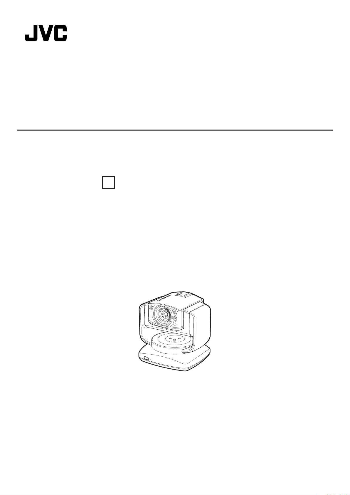
LIVE STREAMING CAMERA
Detailed User Guide
GV-LS2
U
LYT2488-002A
Page 2

Table of Contents
Introduction
Introduction
Verifying the Accessories ......................4
Component Names and Functions .......5
Camera ............................................................. 5
Pantilter ............................................................7
Configuring the Camera Settings
Appropriate for Your Needs ...............8
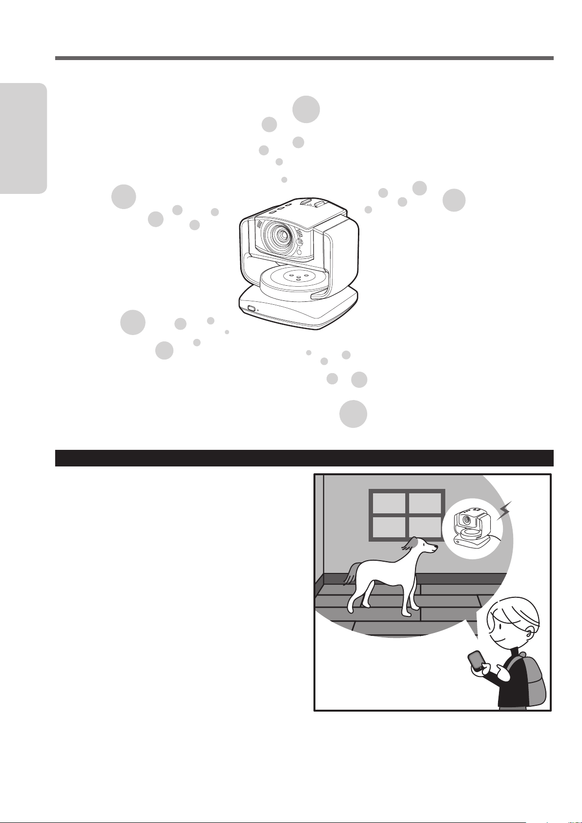
Example 1: Worried about your pet staying at
home alone. ................................................. 8
Example 2: Record birds coming to a feeder on
the balcony. .................................................. 9
Example 3: Live-stream a performance in a
studio. .......................................................... 9
Preparation
Flow of Connection/Setup ...................10
Starting shooting ............................................ 10
Connecting the Camera to Your
Computer ..........................................11
Connecting the AC Adapter .................12
Configuring the Camera Settings
Appropriate for Your Needs .............13
Configuring the initial settings ........................ 13
Changing the settings after changing the
connection destination ............................... 14
Configuring the Camera Settings .......15
Adjusting the clock.......................................... 15
Setting the user name and password ............. 16
Selecting the Format of Images to be
Output/Saved ....................................17
Allowing You to Connect from Outside
(Monitoring Setting) .........................18
Obtaining a DDNS account ............................ 18
Setting up the DDNS account ........................ 18
Adding a camera driver's user ........................ 19
Changing the Connection Destination
...........................................................20
Establishing a wired connection to the access
point ........................................................... 20
Connecting to the access point wirelessly (Wi-
Fi) .............................................................. 21
Connecting to a computer directly (Wi-Fi Direct)
.................................................................. 23
Connecting Multiple Cameras .............24
Attaching the Pantilter .........................25
Attaching the Pantilter ....................................25
Connecting the AC adapter ............................ 26
Removing the pantilter.................................... 26
Establishing a wired connection .........27
Inserting/Removing an SD Card ..........28
Inserting ......................................................... 28
Removing ....................................................... 28
Approximate recording times .......................... 28
Compatible SD cards...................................... 28
2
Page 3

Preparation
Attaching/Removing the Battery .........29
Attaching ........................................................ 29
Use Information
Using the Unit Alone ............................32
Turning on/off the power ................................. 32
Introduction Preparation Use Information
Removing ....................................................... 29
Charging ......................................................... 29
Connecting an External Mic ................30
Connecting to the camera .............................. 30
Attaching to the hot shoe ................................ 30
Connecting to the pantilter ............................. 30
Connecting the AV Cord ......................31
Connecting to the camera .............................. 31
Connecting to the pantilter ............................. 31
Starting/Stopping recording ............................ 32
Controlling from a Web Browser .........33
Logging in ....................................................... 33
Controlling the camera ("MONITOR" tab) ......34
Configuring the camera settings ..................... 36
Managing files stored on the SD card ("FILE
MANAGEMENT" tab) ................................ 37
Checking the message history ("STATUS" tab) ..
38
Using "JVC CAM Control" ...................39
Installing "JVC CAM Control" ......................... 39
Streaming images .......................................... 39
Using the Mobile Terminal ...................40
Names of Apps for mobile terminals .............. 40
Installing the App for mobile terminals ........... 40
Setting Item List ....................................41
"NETWORK" ................................................... 41
"CAMERA/PAN TILTER" ................................. 45
"MANAGE" ..................................................... 46
Troubleshooting ....................................48
Connection ..................................................... 48
Setup .............................................................. 49
Use ................................................................. 51
Error messages .............................................. 53
Lamp Status List ............................................. 55
Resetting to the factory settings ..................... 56
Deleting (Resetting) the connection information
56
Updating the firmware .................................... 57
Battery Pack (optional) ................................... 57
Specifications .......................................58
3
Page 4
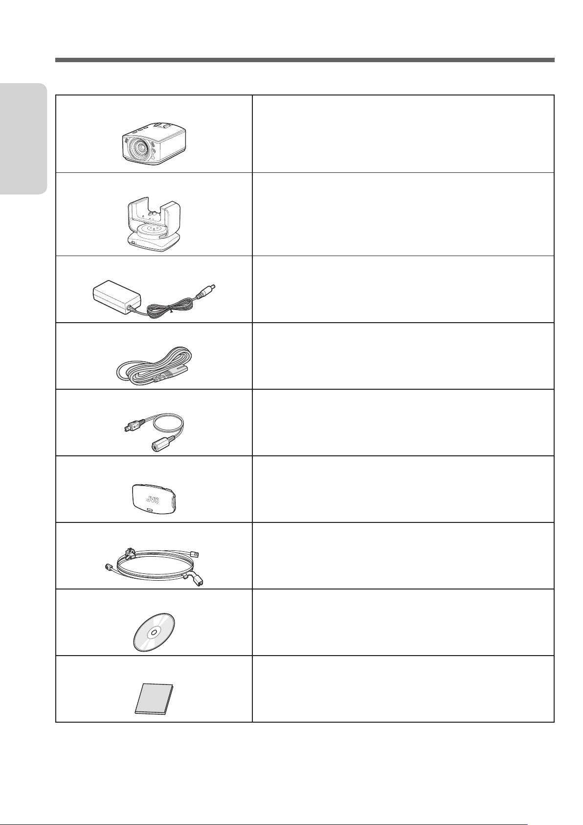
Verifying the Accessories
If any item is missing or damaged, please contact your place of purchase or customer support.
Introduction
Camera
Camera.
Pantilter
AC Adapter UIA324-12
AC cord
Conversion cable
Rear cover
Attach it to the camera before use. Can be panned (right/left) or
tilted (up/down) remotely from a computer or mobile terminal. ( ➭
page 25)
Connect it to the camera or pantilter when using with AC power. (
page 12)
➭
* Attach an AC cord and a conversion cable.
Use it when connecting the AC adapter.
Use it when connecting the AC adapter.
Attach this cover to rear of the camera when carrying the unit, etc.
LAN cable (cross)
Software CD-ROM
Basic User Guide
• Purchase an SD card separately.
• When using the AC adapter overseas, use a commercially available conversion plug appropriate for the country
or region.
Use it to connect the unit, computer, and access point (router).
Also used when you configure the initial settings.
Use it to install the supplied software "JVC CAM Control". ( ➭ page
39)
Describes the basic operations, "Safety Precautions" and
"Cautions".
Please read the instructions carefully before use and operate
correctly as instructed.
4
Page 5

Component Names and Functions
Camera
Front
Back
Introduction
1
3
4
5
2
Internal mic (stereo)
1
Transmits/Records sounds coming through this mic
when no external mic is connected.
Lens
2
Be careful not to touch directly or let anything come
into contact.
LED light
3
Works as a light in dark places. Turn on/off from a
browser. ( ➭ page 36)
Information lamp
4
Can be lit up to indicate the recording status, etc.
Camera sensor
5
Adjusts the white balance automatically. Make sure
that this sensor is not hidden behind any objects.
6
MIC
LAN(OFF)
PLUG IN POWER
DC
AV
7
1
2
RESET
DIRECT WLAN
ETHERNET
8
354
Reset button
1
Resets the network settings when you press and
hold this button with the tip of a paper clip or the
like for 3 seconds or longer while the AC adapter is
connected. ( ➭ page 56)
Use it e.g. if a wrong network setting has been
configured and a connection cannot be established.
LAN terminal
2
Connect a LAN cable to establish a wired connection
to the computer or access point (router). ( ➭ page
11)
Network mode switch
3
Switches the network mode. ( ➭ page 20)
DIRECT: To connect to a computer wirelessly (Wi-Fi)
WLAN: To connect to an access point (wireless LAN
router) wirelessly (Wi-Fi)
LAN(OFF): To establish a wired connection, or to
establish no wireless connection
Battery terminal
4
Connect a separately purchased battery pack (BN-
VG139U) e.g. when using outdoors. ( ➭ page 29)
SD card slot
5
Insert an SD card here to save recorded data to the
card.
For compatible cards, see page 28.
Mic terminal
6
Connect an external mic to transmit/record external
sounds. ( ➭ page 30)
DC connector
7
Connect the supplied AC adapter when using with
AC power. ( ➭ page 12)
AV connector
8
Connect a separately purchased AV cord to watch
videos being transmitted/recorded. ( ➭ page 31)
5
Page 6
Top Bottom
Introduction
1
2
3
4
Hot shoe
1
Mount camera accessories.
* Do not mount any accessories when the pantilter
is attached.
Record button
2
Starts recording. To stop, press this button again.
The lamp indicates the current status.
Off: Recording not in progress
Blinking: Recording in progress
Blinking quickly (for 2 seconds): Recording error
WPS button
3
Press and hold to connect wirelessly (Wi-Fi) in WPS
mode. ( ➭ page 20)
The lamp indicates the current status.
Lit up: Online
Off: Offline
Blinking: Being connected
Power button
4
Press and hold to power on. To power off, press and
hold this button again.
The lamp indicates the current status.
Off: Powered off
Lit up: Powered on
Blinking slowly: Setting being changed
Blinking rapidly: Battery being charged
1
Tripod mounting hole
1
Mount a separately purchased tripod.
* The shooting, WPS, and power buttons blink while the
camera is reset ( ➭ page 56).
6
Page 7
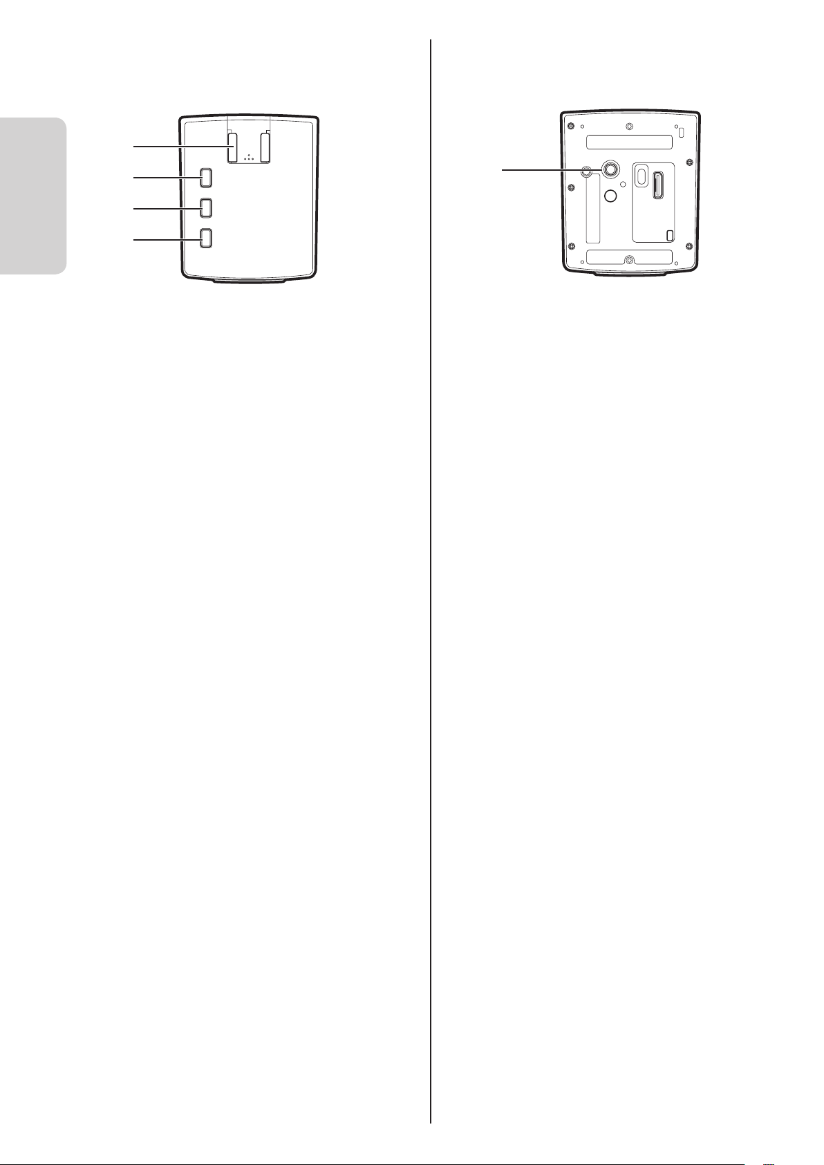
Pantilter
When using the pantilter, connect the AC adapter, AV cord, and external mic to the pantilter.
Front
1
Power button
1
Press and hold to power on. To power off, press and
hold this button again.
Power lamp
2
Indicates the pantilter status.
Off: Powered off
Lit up: Powered on
Blinking: Pantilter error
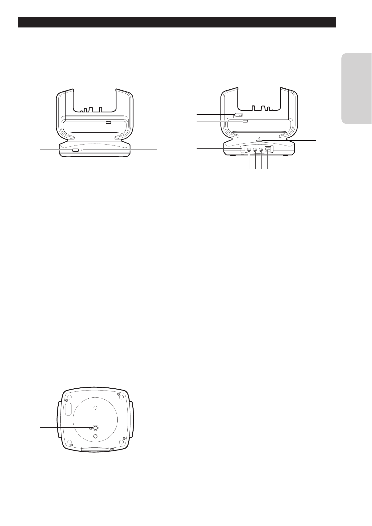
Bottom
2
Back
1
2
PLUG IN
MIC POWER
45
AV DCEXTEND
6 7
3
Tilt lock (TILT LOCK)
1
Face the pantilter right in front and slide the knob to
the left to lock it. Be sure to lock the pantilter when
carrying it.
Camera fixing screw
2
Secures the camera to the pantilter.
Fixing hole for drop prevention
3
Secure the entire unit with a binder or the like.
MIC terminal
4
Connect an external mic to transmit/record external
sounds. ( ➭ page 30)
AV connector
5
Connect a separately purchased AV cord to watch
videos being transmitted/recorded. ( ➭ page 31)
EXTEND terminal
6
Not used.
DC connector
7
Connect the supplied AC adapter when using with
AC power. ( ➭ page 26)
Pan lock (PAN LOCK)
8
Face the pantilter right in front and slide the knob to
the front side to lock it. Be sure to lock the pantilter
when carrying it.
Introduction
8
1
Tripod mounting hole
1
Mount a separately purchased tripod.
7
Page 8
Configuring the Camera Settings Appropriate for Your Needs
The unit can be used for various purposes. See the following examples for how to set up and use appropriately:
Introduction
Power?
• AC adapter ( ➭ page 12)
• Battery ( ➭ page 29)
Connection method?
• Wired connection ( ➭ page 20)
• Wireless (Wi-Fi) connection ( ➭
page 21)
Connection destination?
• Computer ( ➭ page 23)
• Access point (wireless LAN router) ( ➭ page 21)
• Not connected ( ➭ page 32)
Recorded data?
• Save to an SD card. ( ➭ page 17)
• Transmit in high quality.
Watch recorded data?
• Computer ( ➭ page 33)
• Smartphone ( ➭ page 40)
• Video streaming site ( ➭ page 39)
Pantilter? ( ➭ page 25)
( ➭ page 17)
Example 1: Worried about your pet staying at home alone.
Setup
• Attach the pantilter to change the direction as the
pet moves around the room. ( ➭ page 25)
• Connect to the access point (wireless LAN router) via Wi-
Fi.
( ➭ page 21)
Setting
• Configure the DDNS setting to access via a network.
( ➭ page 18)
Use
• Install the App beforehand to view on the smartphone
from outside the home. ( ➭ page 40)
8
Page 9
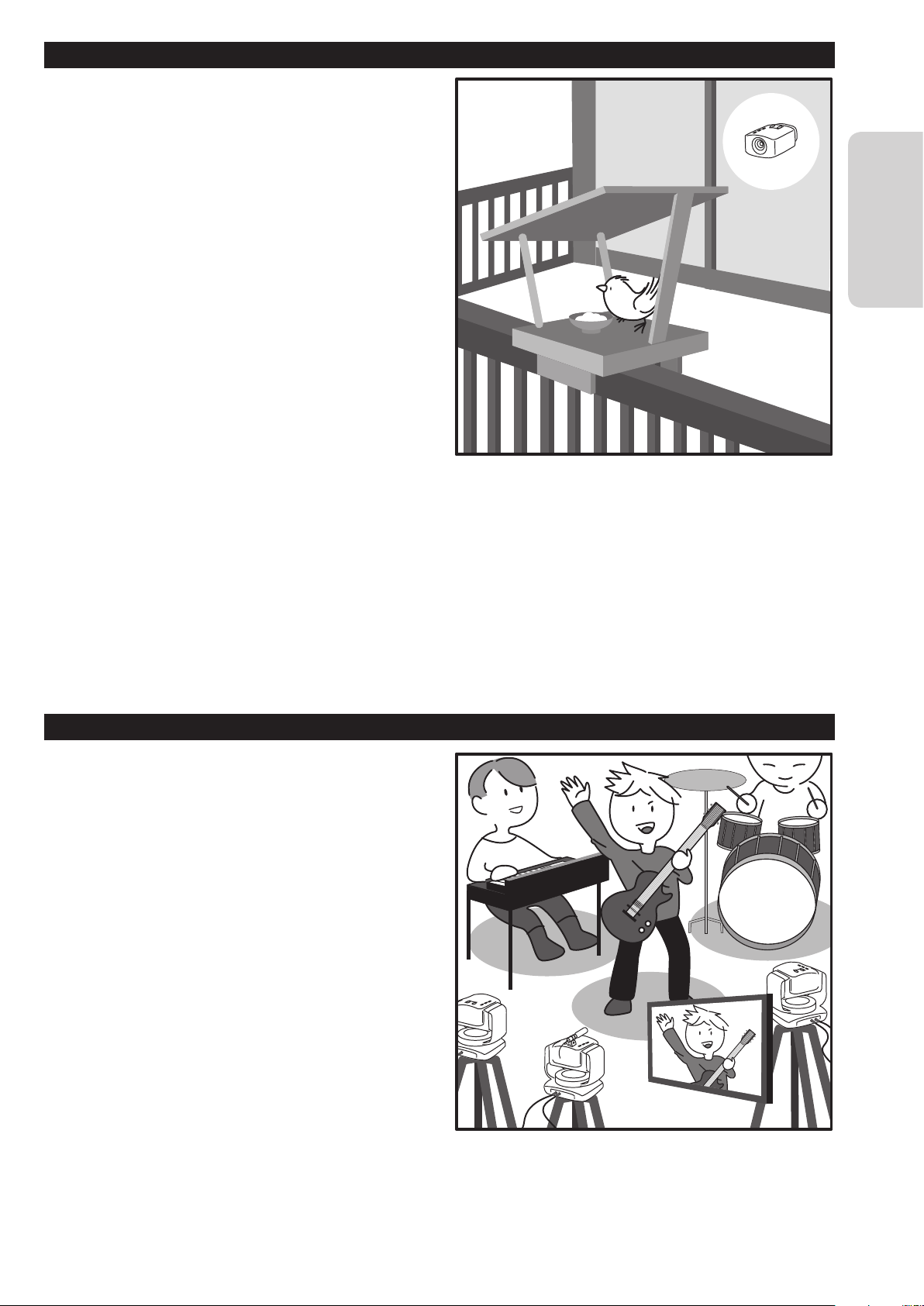
Example 2: Record birds coming to a feeder on the balcony.
Setup
• Use the battery as the camera is set on a high shelf
by the window. ( ➭ page 29)
• Insert an SD card to save recorded data. ( ➭ page
28)
Setting
• Do not connect to the computer or access point
(router).
• Only records when the scene is changed. ("AUTO
REC") ( ➭ page 36)
Use
• After recording, transfer the recorded data to a
computer and then play it. ( ➭ page 37)
Introduction
Example 3: Live-stream a performance in a studio.
Setup
• Use up to three cameras to capture all members.
• Establish a wired connection to the access point
(router) to avoid noise. ( ➭ page 20)
• Set up an external mic in the center of the stage,
and connect it to the camera. ( ➭ page 30)
Setting
• Transmit in high quality. ( ➭ page 17)
Use
• Install the supplied software to stream the powerful
live performance switching the cameras. ( ➭ page
39)
• Use the video streaming site to stream the
performance worldwide. ( ➭ page 39)
In addition...
• Turn on the light in dark places ( ➭ page 36). Please enjoy a variety of usage!
9
Page 10
Flow of Connection/Setup
Connect the unit to the computer, and configure the appropriate settings on a browser.
Starting shooting
1 Connect the camera to your computer via the supplied LAN cable. ( ➭ page 11)
To set up the camera, first connect it to your computer.
Preparation
2 Connect the AC adapter. ( ➭ page 12)
Connect the supplied AC adapter when the connections are complete.
3 Access the unit from a browser to configure the appropriate settings. ( ➭ page 15)
Set the password, image quality, connection destination, etc. Configuring the correct settings allows you to
view recorded data on a computer or smartphone.
4 Secure the camera to the pantilter. ( ➭ page 25)
Secure the camera to the pantilter.
• Attach an optional item if necessary.
Insert/Attach an SD card ( ➭ page 28), battery ( ➭ page 29), external mic ( ➭ page 30), and AV cord (
page 31).
➭
• See "Establishing a wired connection" (page 27) to connect the unit with the LAN cable.
10
Page 11
Connecting the Camera to Your Computer
DIRECT WLAN LAN(OFF)
To set up the camera, first connect it to your computer.
Required operating environment
Browser: Internet Explorer 9 or later
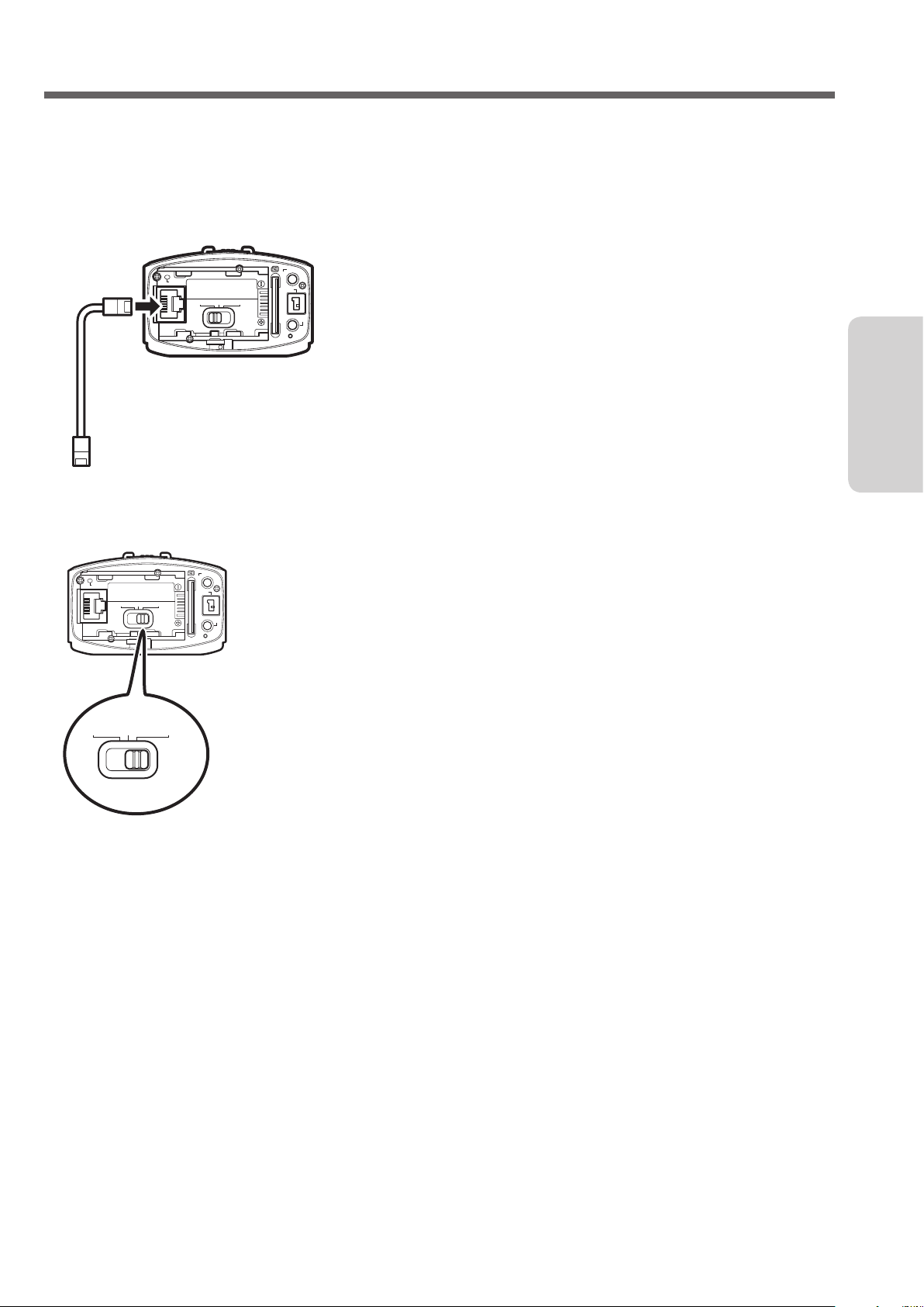
1 Attach the LAN cable to the unit.
MIC
RESET
DIRECT WLAN
LAN(OFF)
ETHERNET
2 Connect the camera to your computer via the LAN cable.
PLUG IN POWER
DC
AV
Preparation
3 Set the network mode switch to "LAN(OFF)".
MIC
LAN(OFF)
PLUG IN POWER
DC
AV
RESET
DIRECT WLAN
ETHERNET
• If the network mode switch is set to [DIRECT] or [WLAN], the LAN terminal cannot be used.
• While the power is on, switching the network mode switch does not change the setting.
11
Page 12
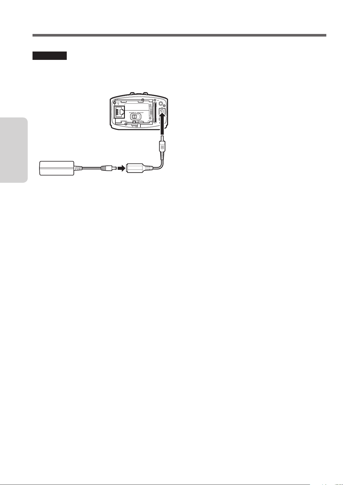
Connecting the AC Adapter
Connect the supplied AC adapter to the DC connector of the camera.
CAUTION
• Be sure to use the supplied AC adapter. Use of another AC adapter may cause a malfunction.
• Turn off the power before connecting/disconnecting the AC adapter.
Preparation
AC adapter (supplied) Conversion cable (supplied)
RESET
ETHERNET
DIRECT WLAN
LAN(OFF)
MIC
PLUG IN POWER
DC
AV
12
Page 13

Configuring the Camera Settings Appropriate for Your Needs
Access the unit from your computer to set the network, streaming, etc.
Required operating environment
Browser: Internet Explorer 9 or later
Configuring the initial settings
To configure the settings for the first time after
purchase, connect the camera directly to your computer
via a LAN cable.
1 Connect the camera to your computer via the
LAN cable. ( ➭ page 11)
2 Press and hold the power button to power on.
The record button starts blinking. Wait until it stops
blinking and off.
3 Configure the network settings for the computer
as follows:
• IP ADDRESS
Other than 192.168.1.100 within the range of
192.168.1.2 to 192.168.1.254
(Example) 192.168.1.23
• SUBNET MASK
255.255.255.0
CAUTION
To restore the settings of your computer after
confirming the performance and completing the
settings, write down the current settings before
changing them.
• To configure the settings only to start using the
unit, refer to "Configuring the Camera Settings"
(page 15), "Selecting a Format of Images
to be Output/Saved" (page 17), "Allowing
You to Connect from Outside (Monitoring
Setting)" (page 18), "Changing the Connection
Destination" (page 20).
• To confirm all the settings, refer to "Setting Item
List" (page 41).
Preparation
4 Start Internet Explorer, and enter
"http://192.168.1.100:8000" in the address bar.
5 Enter the user name and password of the
administrator.
Initial setting: USERNAME "root", PASSWORD
"password".
If login is successful, the setup screen appears.
13
Page 14

Changing the settings after changing the connection destination
To change the settings after changing the connection
destination ( ➭ page 20), visit the following address.
If a wired connection ( ➭ page 20) is established
to the access point
http://(condigured IP address):8000
If a wireless (Wi-Fi) connection ( ➭ page 21) is
established to the access point
http://(camera's IP address):8000
Preparation
If a wireless connection ( ➭ page 23) is
established directly to your computer (Wi-Fi Direct)
http://192.168.1.1:8000
If multiple cameras are connected ( ➭ page 24)
http://(condigured IP address):8000
14
Page 15
Configuring the Camera Settings
This section describes the settings necessary to use the unit. For the "MANAGE" settings not mentioned on these
pages, refer to page 46 .
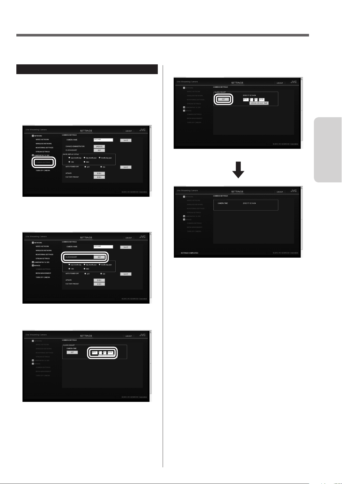
Adjusting the clock
Adjust the internal clock. The time can be displayed
when videos are transmitted.
1 Select "COMMON SETTINGS" in "MANAGE".
If the sub settings are not displayed, click "+" on the
left of "MANAGE".
2 Click the "SET" button on the right of "CLOCK
ADJUST".
4 Click the "SET" button.
Preparation
3 Enter the date and time.
The time is set, and the "COMMON SETTINGS"
screen reappears.
• If an incorrect value is entered, "INVALID DATA
INPUT" appears. Check the entered value.
• If communication to the camera fails,
"COMMUNICATION ERROR OCCURRED"
appears. Check the connection.
• If "PROCESS FAILED" is displayed, check the
camera and computer.
15
Page 16
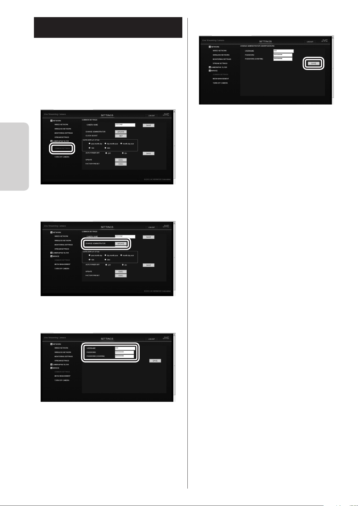
Setting the user name and password
The user name and password set at the time of
purchase are common across all the units of this
model. They should be changed as soon as possible for
security reasons.
1 Select "COMMON SETTINGS" in "MANAGE".
If the sub settings are not displayed, click "+" on the
left of "MANAGE".
Preparation
4 Click the "SAVE" button.
The new user name and password have been set.
2 Click the "UPDATE" button on the right of
"CHANGE ADMINISTRATOR USER/PASSWORD".
3 Enter "USERNAME", "PASSWORD", and
"PASSWORD (CONFIRM)".
16
Enter 1 to 32 characters for the user name, and 8 to
32 characters for the password. (1 byte alphanumeric
characters and symbols only)
Page 17
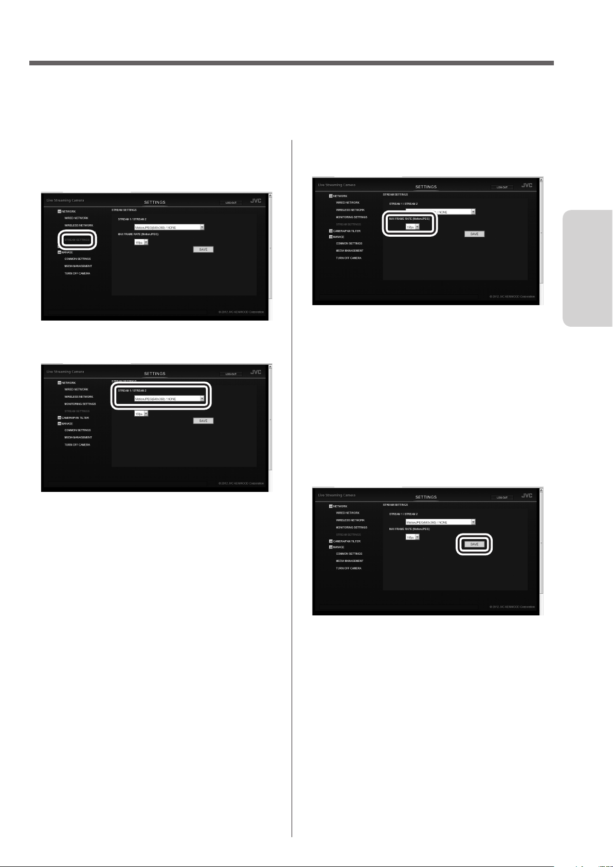
Selecting the Format of Images to be Output/Saved
This unit can output up to two lines of images. Set the output method and image quality appropriate for your needs.
For the "NETWORK" settings not mentioned on these pages, refer to page 41 .
1 Select "STREAM SETTINGS" in "NETWORK".
If the sub settings are not displayed, click "+" on the
left of "NETWORK".
2 Select an option from "STREAM 1/STREAM 2".
3 Select an option from "MAX FRAME RATE
(MotionJPEG)".
Preparation
15 fps:
Outputs images at a rate of up to 15 frames per
second. Suitable for shooting fast-moving subjects.
7.5 fps:
Outputs images at a rate of up to 7.5 frames per
second. Suitable if the communication speed or
terminal's throughput is low.
Selectable only when "STREAM 1/STREAM2" is set
to "MotionJPEG(640x360)/NONE."
MotionJPEG(640x360)/NONE:
Select this to save recorded data inside the unit.
MotionJPEG (640x360) is used to control remotely
from a browser, etc.
MPEG-2 TS (720x576)/MotionJPEG (640x360):
Outputs low resolution data that can be used for
streaming, etc.
MPEG-2 TS (1920x1080)/MotionJPEG (640x360):
Outputs high resolution data that can be used for
streaming, etc.
4 Click the "SAVE" button.
The output image quality has been set.
17
Page 18
Allowing You to Connect from Outside (Monitoring Setting)
To view images from outside, you normally need to obtain a global IP address or URL to access from a browser.
Entering the account of our DDNS service allows you to set these easily.
Obtaining a DDNS account
Access our website from a computer or smartphone for
provisional registration.
1 Visit the following URL to register an account
provisionally.
https://dd3.jvckenwood.com/user/
Preparation
Enter your e-mail address for the user name.
2 Receive the provisional registration mail with
your e-mail address, and visit the URL described
in the mail.
Provisional registration is complete.
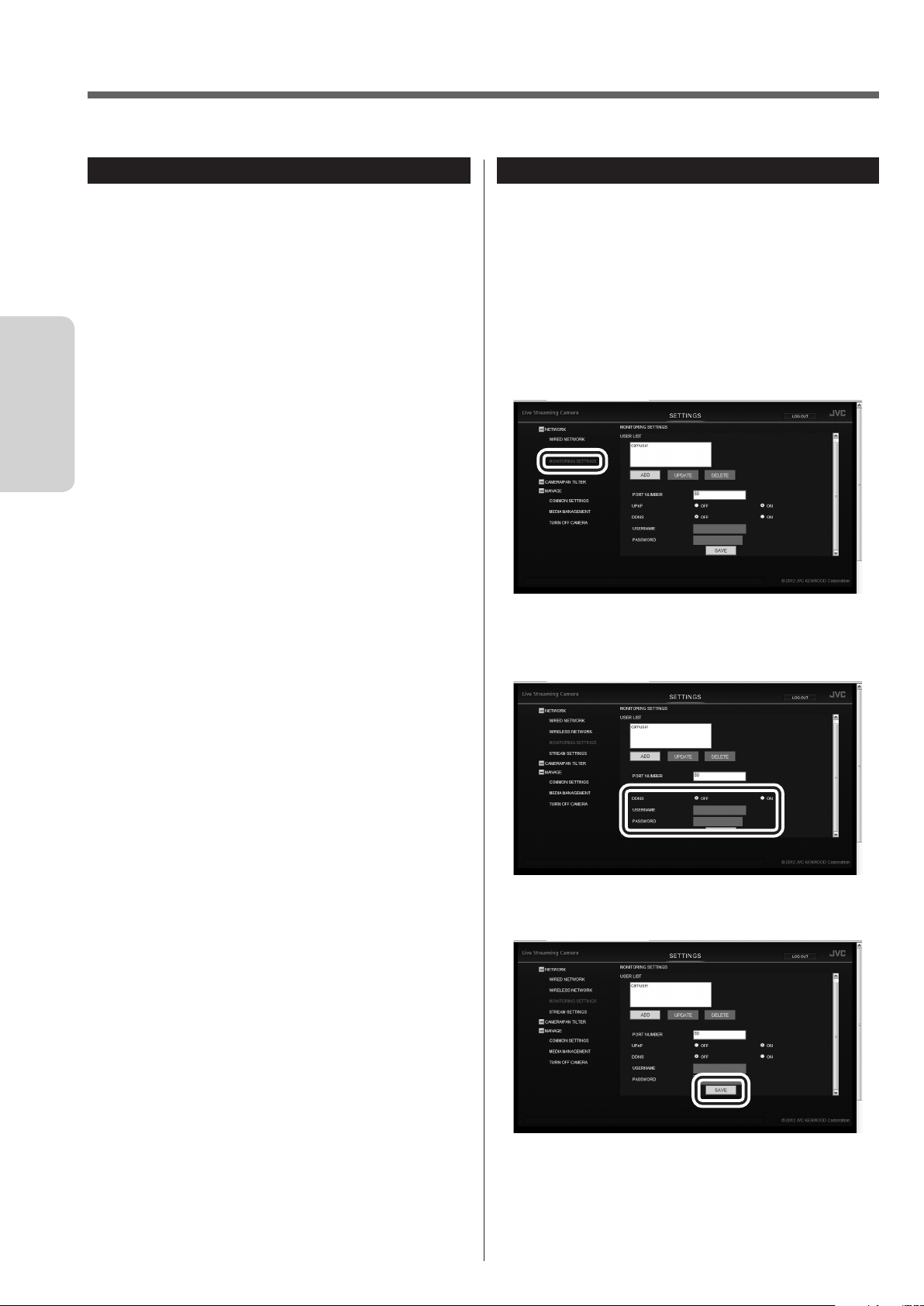
Setting up the DDNS account
Set the user name and password used for provisional
registration on the unit. Follow the steps below within
three days of the provisional registration. If three days
or longer have passed, obtain an account again.
1 Select "MONITORING SETTINGS" in
"NETWORK".
If the sub settings are not displayed, click "+" on the
left of "NETWORK".
2 Set "DDNS" to "ON", and enter "USERNAME"
and "PASSWORD".
3 Click the "SAVE" button.
18
The DDNS account has been set. (The definitive
registration)
• If you do not access the DDNS server for 1 year,
the registration expires.
Page 19

Adding a camera driver's user
To access to the unit using the camera driver ( ➭ page
39), you need to set the user name and password
beforehand. (Up to four users can be registered.)
Initial setting: USERNAME "root", PASSWORD
"password".
They should be changed as soon as possible for
security reasons.
* Multiple users cannot view simultaneously.
1 Select "MONITORING SETTINGS" in
"NETWORK".
If the sub settings are not displayed, click "+" on the
left of "NETWORK".
3 Enter "USERNAME", "PASSWORD", and
"PASSWORD (CONFIRM)".
Enter 1 to 32 characters for the user name, and 8 to
32 characters for the password. (1 byte alphanumeric
characters and symbols only)
4 Click the "SAVE" button.
Preparation
2 Click the "ADD" button.
• Select a user from "USER (JVC CAM driver)" and
click the "UPDATE" button to change the user
name and password of the user.
• Select a user from "USER (JVC CAM driver)" and
click the "DELETE" button to delete the user.
The user has been registered.
19
Page 20

Changing the Connection Destination
If necessary, change the connection destination to the access point (wireless LAN router).
Establishing a wired connection to the access point
1 Select "WIRED NETWORK" in "NETWORK".
If the sub settings are not displayed, click "+" on the
left of "NETWORK".
Preparation
2 Configure the following settings:
CAUTION
• For how to set the access point, refer to the
instruction manual, etc. of the access point.
• When multiple cameras are set up in the same
network, assign different IP addresses so that they
do not duplicate each other.
• If the network setting is set to "AUTO", the camera's
IP address is assigned automatically by the access
point. For values to be assigned, refer to the setting
screen, etc. of the access point.
• If the IP address of the unit is unknown, confirm the
displayed information of the PC application, Android
application or iOS application.
3 Click the "SAVE" button to save the settings.
• IP ADDRESS
First three values separated by dot (.): Same as
those of the access point
Last value: Different from that of the access point
within the range of 1 to 254
(Example) If the access point is 192.168.1.1, set
192.168.1.2.
• SUBNET MASK
Same as the access point
(Example) 255.255.255.0
• DEFAULT GATEWAY
Same as the IP address of the access point
(Example) 192.168.1.1
• PRIMARY DNS
Same as the IP address of the access point
(Example) 192.168.1.1
• SECONDARY DNS
Blank
The settings to be configured on a browser have
been complete. Close the browser, and shutdown
the computer.
4 Press and hold the power button to power off.
5 Connect the camera to the LAN port of the
access point via the LAN cable. ( ➭ page 27)
6 Set the network mode switch to "LAN(OFF)".
7 Press and hold the power button to power on.
When the "WPS" button stops blinking and stays lit,
the connection is complete.
20
Page 21

Connecting to the access point
Searching and connecting to the
wirelessly (Wi-Fi)
Using the WPS function
Connect to the access point equipped with the WPS
function easily.
1 Press and hold the power button to power off.
2 Disconnect the LAN cable that connects the
camera to your computer.
3 Set the network mode switch to "WLAN".
4 Press and hold the power button to power on.
The record button starts blinking. Wait until it stops
blinking and off.
5 Enable the WPS function of the access point.
(Example) Press the "WPS" button.
For how to enable the WPS function, refer to the
instruction manual of the access point.
6 Press and hold the "WPS" button.
When the "WPS" button stops blinking and stays lit,
the connection is complete.
If no connection can be established within two
minutes, the "WPS" button turns off. Try again, or set
up manually.
access point
1 Select "WIRELESS NETWORK" in "NETWORK".
Preparation
If the sub settings are not displayed, click "+" on the
left of "NETWORK".
2 Click the "SEARCH" button.
3 Select an access point to connect to.
If your preferred access point is not in the list, click
the "SEARCH AGAIN" button.
It may not be found if there is a long distance or
interference.
21
Page 22

4 Enter "PASSWORD".
5 Click the "SAVE" button.
Preparation
Connecting manually
1 Select "WIRELESS NETWORK" in "NETWORK".
If the sub settings are not displayed, click "+" on the
left of "NETWORK".
2 Click the "MANUAL" button.
The settings to be configured on a browser have
been complete. Close the browser, and shutdown
the computer.
6 Press and hold the power button to power off.
7 Disconnect the LAN cable that connects the
camera to your computer.
8 Set the network mode switch to "WLAN".
9 Press and hold the power button to power on.
When the "WPS" button stops blinking and stays lit,
the connection is complete.
3 Enter the information, and click the "SAVE"
button.
The settings to be configured on a browser have
been complete. Close the browser, and shutdown
the computer.
4 Press and hold the power button to power off,
and disconnect the LAN cable that connects the
camera to your computer.
22
5 Set the network mode switch to "WLAN".
6 Press and hold the power button to power on.
When the "WPS" button stops blinking and stays lit,
the connection is complete.
Page 23

Connecting to a computer directly
Connecting manually
(Wi-Fi Direct)
Using the WPS function
1 Press and hold the power button to power off.
2 Disconnect the LAN cable that connects the
camera to your computer.
3 Set the network mode switch to "DIRECT".
4 Press and hold the power button to power on.
The record button starts blinking. Wait until it stops
blinking and off.
5 Establish a WPS connection on the computer.
For connection, refer to the instruction manual of the
device.
6 Press and hold the "WPS" button.
When the "WPS" button stops blinking and stays lit,
the connection is complete.
If no connection cannot be established within two
minutes, the "WPS" button turns off. Try again, or set
up manually.
1 Press and hold the power button to power off.
2 Disconnect the LAN cable that connects the
camera to your computer.
3 Set the network mode switch to "DIRECT".
4 Press and hold the power button to power on.
The record button starts blinking. Wait until it stops
blinking and off.
5 Connect to DIRECT-**JVCCAM via wireless LAN
of the computer.
• For connection, refer to the instruction manual of
the device.
• The password is "password" at the time of
purchase.
Preparation
23
Page 24

Connecting Multiple Cameras
To connect multiple cameras, configure the following settings.
1 Select "MONITORING SETTINGS" in
"NETWORK".
If the sub settings are not displayed, click "+" on the
left of "NETWORK".
Preparation
2 Change "PORT NUMBER" (1 to 65535) so that
the numbers do not duplicate between the
cameras.
4 Select "COMMON SETTINGS" in "MANAGE".
If the sub settings are not displayed, click "+" on the
left of "MANAGE".
5 Change "CAMERA NAME" so that the names do
not duplicate between the cameras.
(example)
camera1: 10080
camera2: 10082
camera3: 10083
3 Click the "SAVE" button.
6 Click the "SAVE" button.
24
Page 25

Attaching the Pantilter
The supplied pantilter allows you to pan (move horizontally) and tilt (move vertically) the camera using your
computer or smartphone.
• Remove all cables before attaching the pantilter.
• When using the pantilter, connect the AC adapter, AV cord, and external mic to the pantilter.
• Confirm the hole position on the bottom to attach it.
• Attach the camera firmly, making sure that it is not lifted.
• Hold the pantilter, not the camera, when carrying it. Holding the camera can cause a malfunction.
Preparation
Attaching the Pantilter
1 Push the camera straight down.
Direction (Front)
2 Screw and fix the camera.
• The pantilter does not work properly when placed
on a slant, upside down or on its side.
PLU
MIC
G IN
PO
WE
R
AV
EXTEND
DC
25
Page 26

Connecting the AC adapter
Connect the supplied AC adapter to the DC connector
of the pantilter.
• Be sure to unlock the pantilter before
connecting the AC adapter. ( ➭ page 7)
• Remove all tape from the pantilter.
Preparation
AC adapter (supplied) Conversion cable (supplied)
ETHERNET
Removing the pantilter
To use the camera alone ( ➭ page 32), remove the
pantilter.
1 Loosen the camera fixing screw sufficiently.
MIC
AV DCEXTEND
PLUG IN POWER
DC
LAN(OFF)
AV
PLU
MIC
G
IN
PO
WE
R
AV
EXTEND
DC
2 Hold the unit and pantilter, and pull it straight up.
RESET
DIRECT WLAN
PLUG IN
MIC
POWER
• After connecting the AC adapter, the power turns on
and the pantilter moves automatically for position
adjustment. The pantilter moves everytime the unit
is turned on.
• The power lamp blinks when the position adjustment
fails. Turn off the unit and turn it on again for
readjustment. (The position adjustment may have
failed even if the power lamp is not blinking.)
When the pantilter is not used, connect the AC adapter,
AV cord, and external mic to the camera itself.
26
Page 27

Establishing a wired connection
DIRECT WLAN LAN(OFF)
When establishing a wired connection to the computer or access point, attach the supplied LAN cable as follows.
Required operating environment
Browser: Internet Explorer 9 or later
1 Set the network mode switch to "LAN(OFF)".
MIC
LAN(OFF)
PLUG IN POWER
DC
AV
RESET
DIRECT WLAN
ETHERNET
• If the network mode switch is set to [DIRECT] or [WLAN], the LAN terminal cannot be used.
• While the power is on, switching the network mode switch does not change the setting.
Preparation
2 Attach the conversion cable to the stopper of the LAN cable.
Stopper
3 Attach the LAN cable to the unit in numerical order.
2
1
PLUG IN
MIC
POWER
AV
EXTEND
DC
Hold the joint gently and insert.
3
• Attach the cable without twisting.
• When using a tripod, make sure the cable does not come into contact with its handle.
• Do not put obstacles near the cable. Otherwise, the pantilter may not move properly.
• Do not use cables (AV cable, microphone, etc.) with L-shaped connecters.
• The center position of the camera may differ slightly under circumstances such as at low temperatures; however,
this is not malfunction.
4 Connect the camera to your computer via the LAN cable.
27
Page 28

Inserting/Removing an SD Card
Insert a separately purchased SD card to save recorded data to the card. The saved data can be deleted/
downloaded from a browser.
• Turn off the power before inserting/removing the SD card.
• The saved data can be played back by Windows Media Player 12 ( ➭ page 37).
Inserting
Insert the card straight with the terminal side facing
right.
• Make sure that the write protect switch of the SD
card is not set to LOCK (writing protected).
Preparation
Removing
Push the card in once, and pull it out straight.
Compatible SD cards
Operation confirmed with the following SD cards.
Panasonic
Manufacturer
Video
• Using SD cards (including SDHC/SDXC cards) other
than those specified above may result in recording
failure or data loss.
• Not all SD card operations are guaranteed.
Some operations may not be performed due to
specification changes, etc.
• Do not touch the terminals of the SD card. Doing so
may cause data loss.
TOSHIBA
SanDisk
Class 4 or higher compatible SD
card (2 GB)
Class 4 or higher compatible SDHC
card (4 GB to 32 GB)
Class 4 or higher compatible SDXC
card (48 GB to 64 GB)
(When recording with video
quality "UXP", Class 6 or higher is
recommended.)
28
Approximate recording times
Mode
Capacity
UXP 20 min. 40 min. 1 hr. 20 min. 2 hr. 50 min. 4 hr. 10 min. 5 hr. 40 min.
XP 30 min. 1 hr. 2 hr. 4 hr. 6 hr. 8 hr. 10 min.
SP 40 min. 1 hr. 20 min. 2 hr. 50 min. 5 hr. 50 min. 8 hr. 30 min. 11 hr. 30 min.
EP 1 hr. 40 min. 3 hr. 30 min. 7 hr. 10 min. 14 hr. 40 min. 21 hr. 30 min. 28 hr. 50 min.
The above times are only intended as an approximate guide. They may be shorter depending on the recording
situation.
4 GB 8 GB 16 GB 32 GB 48 GB 64 GB
Page 29

Attaching/Removing the Battery
The camera can run with the battery power only. When the battery (BN-VG139U) (sold separately) is attached,
videos can be transmitted/recorded even in places where the AC adapter cannot be used.
• The battery cannot be used when the pantilter is attached.
• Turn off the power before attaching/removing the battery.
• The following cannot be used while the battery is attached:
– LAN terminal, network mode switch, reset button
CAUTION
• Be sure to use a battery of our manufacture. If a battery not of our manufacture is used, the safety and
performance are not guaranteed.
• Charging may take time or may not be possible in places outside the operating temperature range.
Preparation
Attaching
Insert the battery deeply, and then slide it to the right
until it clicks.
Removing
Slide the battery to the left, and pull it out toward you
while pushing in the lever below the battery.
Approximate charging times
Charging time
BN-VG139U (sold
separately)
6 hr. 10 min.
Approximate recording times
BN-VG139U (sold
separately)
Actual
shooting time
1 hr. 55 min. 2 hr. 55 min.
Continuous
shooting time
Charging
Connect the adapter to the DC connector of the
camera, and turn off the power. Charging starts.
The power button of the camera blinks during charging.
The power button turns off when charging is complete.
29
Page 30

Connecting an External Mic
Connect an external mic to record external sounds.
Connect a commercially available mic to the MIC terminal of the pantilter when it is attached, or of the camera when
not attached.
• Use the plug-in power type.
• Do not use microphone with L-shaped connectors.
• Turn off the power before connecting/disconnecting the mic.
• Without an external mic, the internal mic can record ambient sounds.
• When the sounds are too loud or too low, change the "MIC LEVEL SETTING". ( ➭ page 45)
Preparation
Connecting to the camera
MIC
LAN(OFF)
PLUG IN POWER
DC
AV
RESET
DIRECT WLAN
ETHERNET
Mic (commercially available)
3.5 mm stereo mic jack
f
Attaching to the hot shoe
1 Remove the hot shoe cover.
Connecting to the pantilter
PLUG IN
MIC
AV DCEXTEND
POWER
Mic (commercially available)
3.5 mm stereo mic jack
f
30
2 Attach the mic.
Page 31

Connecting the AV Cord
Connecting to a TV or the like via an AV cord (sold separately) allows you to view images being recorded/
transmitted even without a computer or mobile terminal.
Connect a separately purchased AV cord to the AV connector of the pantilter when it is attached, or of the camera
when not attached.
• Turn off the power before connecting/disconnecting the AV cord.
• Use the f3.5 mm 4-pole mini plug type. Do not use an L-shaped mini plug.
Connecting to the camera
RESET
DIRECT WLAN
ETHERNET
Video input
Video input (Yellow)
Audio input (L) (White)
Audio input (R) (Red)
AV cord (sold separately)
TV, etc.
LAN(OFF)
MIC
PLUG IN POWER
DC
Connecting to the pantilter
Preparation
AV
PLUG IN
MIC
AV DCEXTEND
POWER
Video input
Video input(Yellow)
Audio input (L)(White)
Audio input (R)(Red)
AV cord (sold separately)
TV, etc.
31
Page 32

Using the Unit Alone
Insert an SD card and attach the battery, so you can carry and use the unit as a normal video camera. Set whether
to save recorded videos to the SD card or stream them wirelessly. ( ➭ page 41)
Use
Turning on/off the power
Turning on the power
Press and hold the power button.
The record button starts blinking. Wait until it stops
blinking and off.
Turning off the power
Press and hold the power button again.
The power button turns off.
Starting/Stopping recording
Starting recording
Press the record button.
The record button blinks.
The button blinks quickly for 2 seconds if recording
cannot start. Check the SD card or unit settings.
Stopping recording
Press the record button again.
The record button turns off.
CAUTION
• The power is automatically turned off if "AUTO
POWER OFF" is set to "ON", the unit runs with the
battery, and no operation is performed for 5 minutes.
( ➭ page 46)
• Recording stops automatically as it cannot be
performed for 12 or more consecutive hours.
32
Page 33

Controlling from a Web Browser
You can control the unit from a web browser without installing additional software.
To watch a video via a network, "MONITORING SETTINGS" ( ➭ page 18) must be set.
Required operating environment
OS: Windows 7
Browser: Internet Explorer 9 or later
Logging in
Use "USERNAME" and "PASSWORD" of the
administrator ( ➭ page 16).
1 If the power is not turned on, press and hold the
power button to power on.
The record button starts blinking. Wait until it stops
blinking and off.
2 Start Internet Explorer, and enter "http://
(camera's IP address):80" in the address bar.
• If a wired connection is established, the factory
setting is that the camera's IP address is
"192.168.1.100".
• If the camera is connected wirelessly, the factory
setting is that the camera's IP address is assigned
automatically by the access point. For values to
be assigned, refer to the setting screen, etc. of the
access point.
• To access the camera on the Internet, enter the
URL obtained via the DDNS service instead of
the camera's IP address. ( ➭ page 18)
Use
3 Enter the user name and password of the
administrator.
Initial setting: USERNAME "root", PASSWORD
"password".
4 Click the "LOG IN" button.
If login is successful, the "MONITOR" screen
appears.
33
Page 34

Controlling the camera ("MONITOR" tab)
Control the camera and view images on the "MONITOR" tab.
Use
1
2
3
Tab
1
Switch the display.
"MONITOR"
Control the camera and view streamed images.
"FILE MANAGEMENT"
Delete video files stored on the SD card or
download them to your computer. ( ➭ page 37)
"STATUS"
Check the message history. ( ➭ page 38)
* When you are logged in as a viewer, you can
view the "MONITOR" tab only.
Control panel
2
Control the camera/pantilter.
4
5
6
7
You can change the zoom amount on the
"CAMERA SETTINGS" (page 45).
Pantilter
2
Pan/Tilt the camera in the direction you clicked.
You can change the angle on the "PAN TILTER
SETTINGS" (page 45).
"PRESET" buttons
3
Click the "1", "2", or "3" button to move the camera
to the position assigned to the respective button.
"RETURN TO CENTER" button
4
Reset the pan/tilt position to return the camera to
the front.
"SAVE AS PRESET" button
5
Click this button and then the "1", "2", or "3"
button to preset the current camera position to the
respective button.
34
1
2
3
4
Zoom
1
5
Message bar
3
Displays an error message, etc.
"LOG OUT"
4
Click this to log out.
Status
5
Indicates the current status such as the remaining
battery power.
1 2 3
Pan angle
1
Displays the current pan (right/left) angle (as a
rough guide).
Tilt angle
2
Displays the current tilt (up/down) angle (as a
Page 35

rough guide).
Zoom ratio
3
Displays the current zoom ratio.
4 5 6 7 8
Recording status
4
Indicates the camera status.
STANDBY: Recording not in progress
REC: Recording in progress
Recording mode
5
Recording mode: UXP, XP, SP, EP
SD card
6
Indicates that an SD card can be used.
Remaining recording time
7
Indicates the remaining recording time.
Power status
8
Indicates the power status.
(Green): Remaining battery: 60 % or more
(Green): Remaining battery: 50 to 60 %
(Yellow): Remaining battery: 40 to 50 %
(Yellow): Remaining battery: 30 to 40 %
(Red): Remaining battery: 20 to 30 %
(Red): Remaining battery: 0 to 20 %
: Running with the AC adapter
Use
9 p
Reload button
9
Update images.
Setting button
p
Displays the setting screen. ( ➭ page 36)
"STREAM SETTINGS"
6
Select a stream format.
Record button/Stop button
7
: Start recording.
●
: Stop recording.
■
CAUTION
• Recording stops automatically as it cannot be
performed for 12 or more consecutive hours.
35
Page 36

Configuring the camera settings
Change the camera settings.
* The screen can only be displayed when you are logged in as an administrator.
1
2
3
4
5
6
7
8
9
0
-
=
Use
"AUTO REC"
1
Turn on/off the "AUTO REC" function that records
only when the scene is changed.
When the setting is changed to "ON", the following
settings are automatically changed:
"BRIGHTNESS ADJUST": "AUTO"
"DIS": "OFF"
"LIGHT": "OFF"
While set to ON, you cannot start recording, pan/tilt
the camera, or change the "GAIN UP" setting. The
digital zoom is automatically adjusted to the optical
zoom range.
"FOCUS"*
2
Change the focus setting.
"AUTO": Focuses automatically on the subject when
it moves or changes.
"FIXED": Fixes the current focus position.
"DIS"*
3
Select "OFF", "SOFT", "MEDIUM", or "STRONG" for
the image stabilizer.
"IMPORT" button. (Click the button with a white
sheet of paper shot in full screen.)
"VIDEO QUALITY"*
7
Select "UXP", "XP", "SP", or "EP" for the quality of
videos to be saved to an SD card. For recording
times in each mode, see page 28 .
"LIGHT"
8
Select "OFF", "ON", or "AUTO" for the LED light
status.
"INFO LAMP"
9
Select "OFF" or "ON" for the information lamp.
"GAIN UP"*
0
Select "OFF", "ON", or "AUTO SLOW-SHUTTER" for
how to handle when the image is not bright.
"DATE/TIME RECORDING"
-
Select "OFF" (Not recorded), "UPPER LEFT",
"UPPER RIGHT", "LOWER LEFT", or "LOWER
RIGHT" for the position where the date and time are
recorded.
36
"BRIGHTNESS ADJUST"
4
Select "–6" to "+6" or "AUTO" for the brightness.
"SHUTTER SPEED"
5
Select "1/2" to "1/4000", or "AUTO" for the shutter
speed.
"WHITE BALANCE"
6
Select "AUTO", "FINE", "CLOUD", "HALOGEN",
"MWB" for the control that adjusts the camera's color
sensitivity to best suit the ambient environment.
"MWB" adjusts the white balance based on
the current image you imported by clicking the
"DISPLAY SECOND"
=
Select "OFF" or "ON" for the second display for
"DATE/TIME RECORDING".
* Cannot be changed during shooting.
Page 37

Managing files stored on the SD card ("FILE MANAGEMENT" tab)
Use the "FILE MANAGEMENT" tab to transmit/delete files stored on the SD card.
* The screen can only be displayed when you are logged in as an administrator.
3
1
2
"TRANSFER"
1
To download a video file to your computer, first click
this button. Then click a thumbnail to display the
download screen on a browser.
Thumbnail
2
After clicking "TRANSFER" or "DELETE", click
the thumbnail of the target file to be transferred or
deleted.
"DELETE"
3
To delete a video file, first click this button. Then
click a thumbnail to display the delete confirmation
screen. To delete, click "YES".
Page move
4
Click "PREVIOUS PAGE" or "NEXT PAGE" to switch
the thumbnail pages.
4
Use
Folder/File lists
Folders and files are stored in an SD card as follows.
Folders and files are created when necessary.
JVCCAM_SD]
[
(Management Information)
• Do not delete/move/rename folders and files.
• The saved data can be played back by Windows Media Player 12 ( ➭ page 37).
EXTMOV]
[
MOV_0001.MTS
MOV_0002.MTS
MOV_0003.MTS ←(管理情報が壊れたファイル)
PRIVATE]
[
管理情報
(
[AVCHD]
)
[JVC]
(Video files with defective management information)
[BDMV]
[STREAM]
[BACKUP]
[CLIPINF]
[PLAYLIST]
[INDEX.BDM]
[MOVIEOBJ.BDM]
[XXXXX.MTS]
.
.
.
(Video File)
←(動画ファイル)
37
Page 38

Checking the message history ("STATUS" tab)
Use the "STATUS" tab to check error messages or currently connected users. The "STATUS" tab is categorized into
"CAMERA", "NETWORK", and "LOG IN USER".
* The screen can only be displayed when you are logged in as an administrator.
Use
"CAMERA"
1
Tab
1
Switch the display.
"ERROR INFO"
2
Displays the error history of the camera/pantilter.
"NETWORK"
1
2
"LOG IN USER"
"LOGGED IN USERS"
1
Displays the logged in users.
"DISABLE" button
2
Select a target user from "LOGGED IN USERS" to
disallow connections from the user.
1
2
"ERROR INFO"
1
Displays the network error history.
"SETTING INFO"
2
Displays the current settings.
2
38
Page 39

Using "JVC CAM Control"
The supplied "JVC CAM Control" allows you to control multiple cameras.
Required operating environment
Operating System: Windows® 7 Home Premium (32-bit/64-bit, Pre-install, with SP1)
CPU: Intel® CoreTM 2 Duo 2 GHz or higher (Intel® CoreTM 2 Quad 2.66 GHz or higher when using MPEG-2 TS(HD))
RAM: 2 GB or more
Installing "JVC CAM Control"
1 Insert the supplied software CD-ROM into the
CD/DVD drive of your computer.
2 Click "setup (setup.exe)" on the auto play
window.
• If the auto play window does not appear, double-
click the "setup (setup.exe)" icon in the software
CD-ROM.
• Follow the on-screen instructions to finish the
installation.
• If the user account control window appears, click
"Yes".
• 2 icons will appear on your desktop when the
installation is finished.
Streaming images
Installing the supplied camera driver allows you to use
this unit as a web camera. Use the distribution software
or website for the web camera such as Ustream
Producer (http://www.ustream.tv/producer) to stream
the images.
The camera driver and "JVC CAM Control" are installed
simultaneously.
Use
39
Page 40

Using the Mobile Terminal
You can operate the camera intuitively on the touch panel of a smartphone/tablet terminal. In addition, the camera
can be panned/tilted by moving the tablet terminal.
Use
Names of Apps for mobile terminals
There are three types of Apps for mobile terminals: For
smartphone (Android OS), for Android tablet, and for
iOS. Download the appropriate App.
For smartphone (Android OS)
"JVC CAM Control Single"
Required operating environment: Android OS 2.3 or
later
Download it from Google Play Store.
For Android tablet
"JVC CAM Control Multi"
Required operating environment: Android OS 2.3 or
later, Screen size: 7 inches or more, Resolution: 1024 x
600 or more
Download it from Google Play Store.
For iPhone/iPod touch/iPad
"JVC CAM Control"
Required operating environment: iOS 5.1.1 or later
Download it from App Store.
Installing the App for mobile terminals
1 Download the software appropriate for your
environment.
• Smartphone (Android OS 2.3 or later)
Download "JVC CAM Control Single" from Google
Play Store.
• Android tablet (Android OS 2.3 or later, Screen
size: 7 inches or more, Resolution: 1024 x 600
or more)
Download "JVC CAM Control Multi" from Google
Play Store.
• iPhone/iPod touch/iPad (iOS 5.1.1 or later)
Download "JVC CAM Control" from App Store.
2 Follow the on-screen instructions to finish the
installation.
40
Page 41

Setting Item List
If you log in as an administrator on a browser of your computer, you can change the settings. The settings are
categorized into "NETWORK", "CAMERA/PAN TILTER", and "MANAGE".
To display the setting item list, "Configuring the Camera Settings Appropriate for Your Needs" (page 13)
"NETWORK"
Configure the settings for the network and streaming on "NETWORK". "NETWORK" is categorized into "WIRED
NETWORK", "WIRELESS NETWORK", "MONITORING SETTINGS" and "STREAM SETTINGS".
"WIRED NETWORK"
Change the settings for establishing a wired connection.
1
3
2
"NETWORK SETTINGS"
1
Select "AUTO" or "MANUAL".
If "MANUAL" is selected, enter "IP ADDRESS",
"SUBNET MASK", "DEFAULT GATEWAY",
"PRIMARY DNS", and "SECONDARY DNS"
appropriately for your environment.
"MAC ADDRESS"
2
Displays the MAC address (physical address) of
the unit. It may be required when you access from a
computer or smartphone.
"SAVE" button
3
After changing the above settings, click this button to
save the changes.
"WIRELESS NETWORK"
Change the settings for establishing a wireless
connection.
1
3
4
"DIRECT CONNECTION"
1
Setting for connecting directly to a computer
wirelessly (Wi-Fi).
"SSID", "PASSWORD", "PASSWORD
(CONFIRM)"
Change the SSID and password of the unit. The
SSID and password will be displayed on your
computer. Enter 2 to 25 characters for the SSID,
and 8 to 63 characters for the password.
"ENFORCED GROUP OWNER"
Set whether to become a group owner enforcedly
when connecting directly. Set it to "OFF" when
you cannot connect to a Wi-Fi direct compatible
device. (When it is set to "OFF", you cannot
connect to any Wi-Fi direct incompatible device.)
"MAC ADDRESS"
Displays the MAC address (physical address) of
the unit when connecting to a computer directly
(Wi-Fi Direct). It may be required when you
access from a computer or smartphone.
2
Information
"ACCESS POINT CONNECTION"
2
41
Page 42

Setting for connecting to an access point (wireless
LAN router) wirelessly (Wi-Fi).
"REGISTERED ACCESS POINT"
Lists up to eight access points that were
connected before.
"SELECT" button
Select an access point from "REGISTERED
ACCESS POINT" and click this button to change
the connection destination.
"DELETE" button
Select an access point from "REGISTERED
ACCESS POINT" and click this button to delete
the connection information.
"UPDATE" button
Select an access point from "REGISTERED
ACCESS POINT" and click this button to update
the connection information.
"ADD"
3
Add a connection destination.
"SEARCH" button
Displays the "ADD (SEARCH)" screen to search
and connect to an access point. Up to ten access
points are listed.
"MANUAL" button
Displays the "ADD (MANUAL)" screen to enter
the connection information manually.
1
2
3
"SSID", "AUTHENTICATE METHOD",
1
"PASSWORD"
Enter the values appropriate for your
environment.
"NETWORK SETTINGS"
2
Select "AUTO" or "MANUAL".
If "MANUAL" is selected, enter "IP ADDRESS",
"SUBNET MASK", "DEFAULT GATEWAY",
"PRIMARY DNS", and "SECONDARY DNS"
appropriately for your environment.
"SAVE" button
3
Save the connection information and return to
the "WIRELESS NETWORK" screen.
Information
1
2
3
4
5
6
"SEARCH" button
1
Search an access point again.
"AUTHENTICATE METHOD"
2
Displays the authentication method of the
selected access point.
"PASSWORD"
3
Enter the password used for the connection.
"NETWORK SETTINGS"
4
Select "AUTO" or "MANUAL".
"IP ADDRESS", "SUBNET MASK",
5
"DEFAULT GATEWAY", "PRIMARY DNS",
"SECONDARY DNS"
If "MANUAL" is selected for "NETWORK
SETTINGS", enter the values appropriate for
your environment.
"SAVE" button
6
Save the connection information and return to
the "WIRELESS NETWORK" screen.
"WPS PIN" button
Displays the "ADD (WPS PIN)" screen to connect
in WPS. Enter the displayed PIN code for the base
unit, and click the "START" button.
"START" button
1
Start connection.
"RETURN" button
2
Stop connection and return to the "WIRELESS
NETWORK" screen.
"MAC ADDRESS"
4
Displays the MAC address (physical address) of the
unit when connecting to the access point. It may
be required when you access from a computer or
smartphone.
1
2
42
Page 43

"MONITORING SETTINGS"
Change the settings for connecting via a network.
1
"USER (JVC CAM driver)"
1
Lists the registered users.
For details, refer to page 19 .
"ADD" button
Up to four camera driver's users can be added.
"UPDATE" button
Update the user name and password of the
registered user.
"DELETE" button
Delete the registered user.
2
3
4
5
"PORT NUMBER"
2
Change the port number assigned to the unit, e.g. if
the unit conflicts with other devices.
"UPnP"
3
Select "OFF" or "ON" for the UPnP (Universal Plug
and Play) function. Set it to "OFF" when you connect
to a UPnP-incompatible access point (wireless LAN
router) or multiple UPnP-compatible devices are
connected.
CAUTION
If the camera's network setting is set to "MANUAL",
the UPnP does not work.
In this case, set your access point so that you can
access the camera on the Internet.
"UPnP" may be called as follows depending on the
access point:
– "IP Masquerade"
– "Network Address Translation"
– "Virtual Server"
Information
"DDNS"
4
Select "OFF" or "ON" for the DDNS (Dynamic
Domain Name System) function. To use our DDNS
service, set it to "ON", and enter "USERNAME" and
"PASSWORD". ( ➭ page 18)
"SAVE" button
5
After changing the above settings, click this button to
save the changes.
43
Page 44

"STREAM SETTINGS"
Format for transmitting/recording.
1
2
"STREAM 1 / STREAM 2"
1
Select the quality of images to be streamed from the
following:
"MotionJPEG(640x360)/NONE"
"MPEG-2 TS (720x576)/MotionJPEG (640x360)"
"MPEG-2 TS (1920x1080)/MotionJPEG (640x360)"
"MAX FRAME RATE (MotionJPEG)"
2
Select "15fps" or "7.5fps" for the maximum frame
rate of MotionJPEG.
"SAVE" button
3
After changing the above settings, click this button to
save the changes.
3
Information
44
Page 45

"CAMERA/PAN TILTER"
Configure the settings for the camera and pantilter on "CAMERA/PAN TILTER". Categorized into "CAMERA
SETTINGS" and "PAN TILTER SETTINGS".
"CAMERA SETTINGS"
Change the camera settings.
AUTO ZOOM RESET
1
Select "OFF" or "ON" for the function that resets the
zoom ratio automatically if no operation is performed
for 5 minutes.
WIND CUT
2
Select "OFF" or "ON" for the function that reduces
noise such as wind sounds.
MIC LEVEL SETTING
3
Select "+2", "+1", "0", "-1", or "-2" for the audio input
level of an external mic.
When the sounds are too loud, set it to a smaller
value. When the sounds are too low, set it to a larger
value.
MAX ZOOM RATIO
4
Select the zoom method and maximum ratio. The
options vary depending on the model.
Select "10X/OPTICAL", "16X/DYNAMIC", "64X/
DIGITAL", or "200X/DIGITAL".
1
2
3
4
5
6
7
"PAN TILTER SETTINGS"
Change the pantilter settings.
AUTO RESET POSITION
1
Select "OFF" or "ON" for the function that resets
the camera position automatically if no operation is
performed for 5 minutes.
Pantilter rotation angle
2
ROTATE ANGLE (PAN1)
Set the value within the range of 1 to 90 degrees
for the angle rotated when the inside pan button is
pressed.
ROTATE ANGLE (PAN2)
Set the value within the range of 1 to 90 degrees
for the angle rotated when the outside pan button
is pressed.
ROTATE ANGLE (TILT1)
Set the value within the range of 1 to 70 degrees
for the angle rotated when the inside tilt button is
pressed.
ROTATE ANGLE (TILT2)
Set the value within the range of 1 to 70 degrees
for the angle rotated when the outside tilt button is
pressed.
1
2
3
Information
ZOOM AMOUNT (ZOOM1)
5
Select "x1", "x2", or "x3" for the amount zoomed
when the inside button is pressed.
ZOOM AMOUNT (ZOOM2)
6
Select "x1", "x2", or "x3" for the amount zoomed
when the outside button is pressed.
"SAVE" button
7
After changing the above settings, click this button to
save the changes.
"SAVE" button
3
After changing the above settings, click this button to
save the changes.
45
Page 46

"MANAGE"
Configure the settings for the administrator and hardware on "MANAGE". Categorized into "COMMON SETTINGS",
"MEDIA MANAGEMENT" and "TURN OFF CAMERA".
"COMMON SETTINGS"
Change the settings of the administrator and camera.
1
2
3
4
5
6
7
"CAMERA NAME"
1
Enter 1 to 15 characters for the camera name
displayed during viewing. (1 byte alphanumeric
characters only)
"CHANGE ADMINISTRATOR USER/PASSWORD"
2
Click the "UPDATE" button on the right to change
the user name and password of the administrator. (
page 16)
➭
"MEDIA MANAGEMENT"
Format the SD card.
"CLOCK ADJUST"
3
Click the "SET" button on the right to set the
internal clock. ( ➭ page 15)
"DATE DISPLAY STYLE"
Information
4
Select "year.month.day", "day.month.year",
or "month.day.year" for the format of the date
displayed during viewing.
In addition, select "12H" (12-hour format) or "24H"
(24-hour format) for the time display.
"AUTO POWER OFF"
5
Select "OFF" or "ON" for the function that turns
off the power automatically if the unit runs with
the battery and no operation is performed for 5
minutes.
"UPDATE"
6
Write the update data on the SD card, and then
click the "EXEC" button to update the firmware. ( ➭
page 57)
46
"FACTORY PRESET"
7
Click the "EXEC" button to reset all the settings to
factory default. ( ➭ page 56)
Page 47

"TURN OFF CAMERA"
Click the "EXEC" button to turn off the camera's power
remotely.
CAUTION
* The power cannot be turned on remotely.
Information
47
Page 48

Troubleshooting
Connection
Problem Check Refer to
The battery cannot be charged.
The power does not turn on when
the battery is used.
The SD card cannot be inserted. • Check the orientation of the card. page 28
The power does not turn on when
the pantilter is attached.
• Check the remaining battery. The battery is no longer
charged if already full.
• Charge the battery.
• Check if the connector is dirty. If it is dirty, clean it
with a cotton swab or the like.
• Check if the camera is attached firmly to the pantilter.
• Check if the AC adapter is connected to the pantilter.
page 35
page 29
page 25
page 26
Information
48
Page 49

Setup
Problem Check Refer to
You cannot connect to the unit even
when you are at home.
(You are requested to enter the
URL.)
You entered the URL, but the unit
cannot be found.
(When connecting on the Internet)
• Check if the wireless (Wi-Fi) connection is complete.
• Check if the connection destination of a computer or
mobile terminal is set to the camera.
• Power on the unit, computer and mobile terminal again,
and retry.
• Check if the UPnP function of the access point (wireless
LAN router) is activated. You cannot be connected if it
is deactivated or incompatible.
• You cannot be connected if multiple access points are
used.
• Check if DDNS is set correctly.
• Check if the UPnP function of the unit is activated. You
cannot be connected if it is deactivated.
• UPnP is not averrable if you set the camera network (IP
address) manually.
• Check if the port number set on the unit is unique and
set to be used on the access point.
• Power on the unit, computer and mobile terminal again,
and retry.
page 20
–
–
page 18
page 43
page 43
page 43
–
You entered the URL, but the unit
cannot be accessed.
(You are requested to enter the
user name and password.)
When the unit is connected, the
Internet cannot be accessed from a
computer.
The connection is interrupted,
or "COMPATIBLE DEVICE NOT
FOUND" is displayed.
• Enter the user name and password. For the
administrator's account, the initial setting of the user
name is "root", and that of the password is "password".
• While the unit is connected directly to the computer,
the computer cannot be connected to the access point
(wireless LAN router).
• Reconnect the computer to the access point. If the
computer is unintentionally connected to the unit,
delete the setup information on the unit from the
computer.
• Set the network mode switch of the unit to other than
"DIRECT".
• Retry to connect in a better reception environment.
If there is a long distance or interference or if there
is a microwave or another wireless device nearby,
the communication speed may slow down or the
connection may not be established.
• Power on the computer and mobile terminal again, and
retry.
page 16
Information
page 5
–
49
Page 50

Problem Check Refer to
The access point (wireless LAN
router) cannot be found.
• Retry to connect in a better reception environment.
If there is a long distance or interference or if there
is a microwave or another wireless device nearby,
the communication speed may slow down or the
connection may not be established.
• If a stealth SSID is assigned to the access point, turn it
off.
• If there are many access points, the target access point
may not be found. In this case, set up manually.
page 21
The access point (wireless LAN
router) cannot be connected.
You do not know the target access
point (wireless LAN router).
Information
• If connected manually, check if the SSID and
authentication method are correct.
• The initial setting of the access point is usually
described on the unit or in the instruction manual. Refer
to the unit or instruction manual.
–
–
50
Page 51

Use
Problem Check Refer to
Shooting stopped automatically.
• Shooting stops automatically as it cannot be
performed for 12 or more consecutive hours.
• The unit stops automatically to protect the circuit
when the temperature rises. Turn off the unit, wait for
a while, and turn it on again.
–
A recorded file cannot be found.
Brightness changes irregularly.
The focus is not adjusted
automatically.
The motion is choppy.
Images are dark.
The color looks different. • Set “WHITE BALANCE” accordingly. page 36
Sound or video is interrupted or
slow.
• No file is saved if the playback time is less than one
second.
• "AUTO" of "BRIGHTNESS ADJUST" may not work
properly depending on the situation, e.g. if there are
multiple light sources. Set it up manually.
• If you are recording in a dark place or a subject that
has no contrast between dark and light, set "FOCUS"
to "FIXED".
• Use a high speed SD card (Class 4 or higher).
• Check if the terminals of the SD card are dirty or
there are too many files. If the card is formatted, the
write speed may be improved.
• Check if the line speed and computer performance
are high enough.
• Turn on the internal light.
• Check the "BRIGHTNESS ADJUST" and "GAIN UP"
settings.
• Check if the line speed and computer performance
are high enough.
–
page 36
page 36
page 28
page 46
–
page 36
–
Information
The computer cannot recognize the
SDXC card.
Data cannot be saved to the SD
card.
• Confirm and update the Operating System of your
computer.
• Windows Vista and Windows 7 may need to be
updated.
• Mac OS X must be updated to 10.6.5 or later.
• Set "STREAM 1 / STREAM 2" to
"MotionJPEG(640x360)/NONE".
• When using a new SD card or one that was used with
other devices, format the card.
–
page 44
page 46
51
Page 52

Problem Check Refer to
Camera images do not appear./
Camera images are gone.
• Camera images disappear if no operation is
performed for 120 hours. Perform one of the following
so that images reappear:
– Press the shooting button. (Shooting starts.)
– Operate the pantilter.
– Press the reload button.
– Disconnect and then connect the AV cable.
• Do not connect the AV cable to the camera and
pantilter simultaneously.
• Camera images disappear automatically as it cannot
transmit images 12 or more consecutive hours. Press
the reload button to display images.
–
The pantilter does not work./The
center position of the camera
differs.
Information
• Connect the AC adapter to the pantilter. If the adapter
is connected to the camera, the pantilter does not
work.
• Use the supplied LAN cable. Secure it with a stop.
• Be careful not to twist the cable when securing it.
• When the LAN cable is in contact with the floor, etc.,
the pantilter may not work properly due to cable
friction.
• The pantilter may not work properly when placed on
a slant.
• If a mic or the like is attached to the hot shoe, remove
it.
• Before attaching the camera to the pantilter, remove
the battery from the camera.
• Do not touch the camera during position adjustment.
• The center position of the camera may differ slightly
under circumstances such as at low temperatures;
however, this is not malfunction.
page 26
page 27
page 27
page 27
page 27
page 30
page 29
page 27
page 27
52
Page 53

Error messages
Message Check Refer to
PLEASE INSERT MEMORY CARD! • To record, insert an SD card into the camera. page 28
NEED TO FORMAT MEMORY
CARD.
THIS CARD CANNOT BE USED
FOR RECORDING OR EDITING
ON THIS CAMERA
INSUFFICIENT AVAILABLE SPACE
SCENE QUANTITY EXCEEDED
LIMIT
CHECK CARD'S WRITE
PROTECTION SWITCH
VIDEO MANAGEMENT FILE
IS DAMAGED, RECOVERY IN
PROGRESS
MANAGEMENT FILE IS
DAMAGED
• If a card is used for the first time after purchase or
has been used with other devices, it may need to be
formatted with this unit.
• Format the card. page 46
• Available space is insufficient. Delete unnecessary
files.
• There are too many recorded files. Delete unnecessary
files.
• The write-protection switch of the SD card is set to the
"LOCK" position. Unprotect it.
• The management file must be recovered e.g. after
the SD card read/write operation is performed on a
computer, etc. Wait until it completes.
• The management file could not be recovered. Format
the SD card.
page 46
page 37
page 37
–
–
page 46
RECORDING FAILURE
RECORDING CANCELLED
MEMORY CARD ERROR! • The SD card cannot be recognized. Check the card. page 28
COMPATIBLE DEVICE NOT
FOUND
COMMUNICATION ERROR
OCCURRED
UNABLE TO LOG IN
CHECK THE USERNAME AND
PASSWORD
INVALID OPERATION
UNABLE TO SWITCH DURING
RECORDING
• The recorded file could not be saved. Check the SD
card.
• The file could not be saved, and recording was
cancelled. Check the transmission speed of the card.
• No WPS-compatible device can be found. Check if
there is a distance or interference between the devices.
• Check the connection and destination device. –
• Enter the correct user name and password. For the
administrator's account, the initial setting of the user
name is "root", and that of the password is "password".
• You cannot operate the camera/pantilter while the
administrator is operating it.
• You cannot open the "FILE MANAGEMENT" tab during
recording. Stop recording.
page 28
page 28
page 34
–
–
–
Information
UNABLE TO UPDATE DURING
RECORDING
INVALID DATA INPUT
THE USERNAME IS ALREADY IN
USE
• You cannot change the "DIS"/"GAIN UP" setting during
streaming/recording. Stop streaming/recording.
• Check the type of the entered text (character, number,
single-byte/double-byte, etc.).
• You cannot register a user name already in use. Enter
another user name.
–
–
–
53
Page 54

Message Check Refer to
• The two passwords entered on the change password
INCORRECT PASSWORD
USE AC ADAPTER • When updating the firmware, connect the AC adapter. page 12
screen are different. Enter the same password in the
two fields.
–
NO UPDATES AVAILABLE
UPDATE CORRUPTED
INSTALLED UPDATE ON THIS
CAMERA CAN NOT BE USED
UPDATE IS SAME OR OLDER
VERSION. NO INSTALLATION
REQUIRED
POWER TURNED OFF TO
CONSERVE BATTERY POWER
(12 HOURS LIMITATION)
RECORDING CANCELLED
ABNORMALITY OCCURRED IN
PAN TILTER
POWER TURNED OFF AS
CAMERA TEMPERATURE IS TOO
Information
HOT
PROCESS FAILED
• Check if the update file is written in the correct folder
on the SD card.
• Retrieve the firmware update file, and copy it to the SD
card.
• Obtain the updater for the unit. –
• The firmware has already been updated. There is no
need to update it.
• The power is automatically turned off if "AUTO POWER
OFF" is set to "ON", the unit runs with the battery, and
no operation is performed for 5 minutes.
• Recording stops automatically as it cannot be
performed for 12 or more consecutive hours.
• Turn on the power again, and retry. page 7
• Wait for a while, and turn on the power again. page 6
• Setup, file deletion, etc. failed for some reason. Check
the connection, and retry.
–
–
–
page 46
–
–
54
Page 55

Lamp Status List
Status
POWER
(Camera)
Record WPS
Power off Turns off – – –
Power off (Charging) Blinks slowly – – –
Power on (Activating) Lights Blinks – –
Power/Activation
Power on (Activation completed) Lights – – –
Wireless/Wired disabled *
Attempting connection *
Connection established *
Network
1
2
3
– – Turns off –
– – Blinks slowly –
– – Turns off –
Attempting WPS – – Blinks –
No access (Unrelated to the
existence of media)
– Turns off – –
POWER
(Pantilter)
Blinks quickly
Shooting impossible –
Media
(only for 2
seconds)
– –
Accessing media – Blinks – –
Shooting – Blinks – –
Power off (Pantilter) – – – Turns off
Power on (Pantilter) – – – Lights
Pantilter
Pantilter error – – – Blinks quickly
Changing the settings Blinks – – –
Resetting Blinks Blinks Blinks –
Etc.
Updating the firmware Blinks Blinks Blinks –
Formatting media Blinks Blinks Blinks –
Information
*1 Wireless (Access point) mode: No access point is registered.
Wireless (Direct) mode: –
Wired mode : LAN cable is not connected.
*2 Wireless (Access point) mode : The access point is registered, but connection has not been established yet.
Wireless (Direct) mode: No device is connected.
Wired mode : LAN cable is connected and connection has been established.
*3 Wireless (Access point) mode: Connection to the access point is established.
Wireless (Direct) mode: The device is connected to the unit.
Wired mode : LAN cable is connected, and LAN setting has been received from the DHCP
server or LAN setting is fixed.
55
Page 56

Resetting to the factory settings
Reset all the unit settings to factory default.
1 Select "COMMON SETTINGS" in "MANAGE".
If the sub settings are not displayed, click "+" on the
left of "MANAGE".
2 Click the "EXEC" button on the right of
"FACTORY PRESET".
Deleting (Resetting) the connection information
Delete the connection information stored in the unit.
Press and hold the reset button of the camera for
three seconds with the AC adapter connected.
The shooting, WPS, and power buttons blink while the
camera is reset. Wait until it stops blinking and stays lit.
Information
3 To execute, click the "EXEC" button.
56
Page 57

Updating the firmware
The firmware updater is sometimes uploaded to our
website for operational improvement.
(There is no notice on our website until the firmware
updating program is provided.)
http://www3.jvckenwood.com/dvmain/support/
download/index.html
1 Copy the update file to an SD card, and insert
the card into the unit.
Do not copy other files.
2 Select "COMMON SETTINGS" in "MANAGE".
If the sub settings are not displayed, click "+" on the
left of "MANAGE".
3 Click the "EXEC" button on the right of
"UPDATE".
4 Make sure that the AC adapter is connected, and
click the "YES" button.
CAUTION
• While updating the firmware, do not turn off the
power or remove the SD card. If the update fails, the
unit may no longer be usable, e.g. the power can no
longer be turned on.
Battery Pack (optional)
The supplied battery pack is a lithium-
ion battery. Before using the supplied
battery pack or an optional battery
pack, be sure to read the following
cautions:
• To avoid hazards
... do not burn.
... do not short-circuit the terminals. Keep it away
from metallic objects when not in use. When
transporting, carry the battery in a plastic bag.
... do not modify or disassemble.
... do not expose the battery to temperatures
exceeding 60°C (140°F), as this may cause the
battery to overheat, explode or catch fire.
... use only specified chargers.
• To prevent damage and prolong service life
... do not subject to unnecessary shock.
... charge within the temperature range of 10°C to
35°C (50°F to 95°F). Cooler temperatures require
longer charging time, or in some cases stop
charging at all.
Warmer temperatures prevent complete charging,
or in some cases stop charging at all.
... store in a cool, dry place. Extended exposure to
high temperatures will increase natural discharge
and shorten service life.
... keep a 30% battery level (
is not to be used for a long period of time.
In addition, fully charge and then fully discharge
the battery pack every 6 months, then continue to
store it at a 30% battery level ( ).
... remove from charger or powered unit when not in
use, as some machines use current even when
switched off.
... do not drop or subject to strong impact.
Terminals
) if the battery pack
Information
57
Page 58

Specifications
Camera
Power supply Using the AC adapter: DC 12 V, Using a battery pack: DC 3.6 V
Power consumption 5.6 W (when using the pantilter), Rated current consumption: 2 A
Dimensions (mm) 73 x 48 x 90 (2 7/8'' x 1 15/16'' x 3 9/16'') (W × H × D)
Mass Approx. 229 g (0.51 lbs) (camera only)
Operating environment
Image element 1/2.3" 12,400,000 pixels
Recording area 5,400,000 to 2,070,000 pixels (DIS: OFF, dynamic zoom: ON)
Lens
Lowest illumination
Zoom
Recording media SD/SDHC/SDXC card (commercially available)
Network standard
Clock battery Rechargeable battery
Information
Estimated under the conditions of DIS being set to "OFF" for the wide(W) end and to "MEDIUM" for the tele (T) end.
*1
Allowable operating temperature: 0 ˚C to 40 ˚C (32 ˚F to 104 ˚F)
Allowable storage temperature: – 20 ˚C to 50 ˚C (− 4 ˚F to 122 ˚F)
Allowable relative humidity: 35 % to 80 %
F1.2 – F2.8, f = 3.76 mm (3/16'') to 37.6 mm (1 1/2'')
35 mm (1 7/16'') conversion: 29.5 mm (1 3/16'') to 476 mm (18 3/4'') (dynamic
zoom: ON)
35 mm (1 7/16'') conversion: 29.5 mm (1 3/16'') to 407 mm (16 1/16'') (dynamic
zoom: OFF)*
10 lux (GAIN UP: ON)
1 lux (GAIN UP: AUTO SLOW-SHUTTER)
Optical zoom: Up to 10x
Dynamic zoom: Up to 16x (DIS: OFF)
Digital zoom: Up to 200x
Wired: 10BASE-T/100BASE-TX
Wireless: IEEE 802.11b/g/n 2.4GHz band only
1
Connectors
AV output connector
Mic connector
Video output: 1.0 V (p-p), 75
Audio output: 218 mV (rms), 1 k
3.5 mm mini jack: stereo, analog, plug-in power supported
f
Video
AVCHD standard
Recording format
Extension .MTS
Signal system NTSC standard
Image quality (Video)
Sound quality (Audio) 48 kHz, 256 kbps
Video: AVC/H.264
Audio: Dolby Digital 2ch
UXP: 1920 x 1080 pixels Average Approximate 24 Mbps
XP: 1920 x 1080 pixels Average Approximate 17 Mbps
SP: 1920 x 1080 pixels Average Approximate 12 Mbps
EP: 1920 x 1080 pixels Average Approximate 4.8 Mbps
W
W
58
Page 59

Stream output format
Stream 1 Stream 2
Format 1
Format 2
Format 3
Video JPEG (640x360)
Audio LPCM 16 kHz 16 bit 1 ch
System MPEG-2 TS —
Video H.264 Main Profile (720x576) JPEG (640x360)
Audio AAC 48 kHz 16 bit 2 ch LPCM 16 kHz 16 bit 1 ch
System MPEG-2 TS —
Video H.264 High Profile (1920x1080) JPEG (640x360)
Audio AAC 48 kHz 16 bit 2 ch LPCM 16 kHz 16 bit 1 ch
AC adapter (UIA324-12)
Power supply AC 100 V – 240 V, 50 Hz/60 Hz
Output DC 12 V, 2 A
Allowable operating
temperature
Dimensions (mm)
Mass Approx. 175 g (0.39 lbs)
0°C to 40°C (32°F to 104°F) (10°C to 35°C (50°F to 95°F) during charging)
44 x 29 x 96 (1 3/4'' x 1 3/16'' x 3 13/16'') (W × H × D: excluding cord and AC
plug)
None
Pantilter (GV-LS2WUP)
Dimensions (mm) 128 x 113 x 108 (5 1/16'' x 4 1/2'' x 4 5/16'') (W × H × D)
Mass Approx. 625 g (1.4 lbs)
Angle range
• Specifications and appearance are subject to change without notice due to product improvements.
Pan: ±150° (at wireless connection) / ±100° (at wired connection), Tilt: –30° to +
40°
Information
59
Page 60

©2012 JVC KENWOOD Corporation 0812HO-MW-VM
 Loading...