

Page 1
MINI VIDEO PRINTER
G V -HT1
ENGLISH
Please visit our CyberCam Homepage on
the World Wide Web and answer our Consumer Survey (in English only):
http://www.jvc-victor.co.jp/index-e.html
INSTRUCTIONS
For Customer Use:
Enter below the Model No. and Serial
No. which is located on the bottom of
cabinet. Retain this information for
future reference.
Model No.
Serial No.
LYT0178-001A
EN
Page 2
2 EN
Dear Customer,
Thank you for purchasing this Printer.
Before use, please read the safety
information and precautions contained
in the following pages to ensure safe
use of this product.
Using This Instruction Manual
•All major sections and subsections are listed
in the Table Of Contents (墌 pg. 8, 9).
•Notes appear after most subsections. Be
sure to read these as well.
•Basic and advanced features/operation are
separated for easier reference.
It is recommended that you . . .
... refer to “Controls, Indicators and Connec-
tors” (墌 pgs. 12 – 15) and familiarize
yourself with button locations, etc. before
use.
... read thoroughly the Safety Precautions
and Safety Instructions that follow. They
contain extremely important information
regarding the safe use of your new Printer .
You are recommended to carefully
read the cautions on page 5 before
use.
WARNING:
TO PREVENT FIRE OR SHOCK HAZARD,
DO NOT EXPOSE THIS UNIT TO RAIN
OR MOISTURE.
CAUTIONS:
䡲 To prevent shock, do not open the cabinet.
No user serviceable parts inside. Refer
servicing to qualified personnel.
䡲 When you are not using the AC Power
Adapter/Battery charger for a long period of
time, it is recommended that you disconnect
the power cord from AC outlet.
The AA-V68U AC Power Adapter should be
used with:
AC 120 V`, 60 Hz in the USA and Canada,
AC 110 – 240 V`, 50/60 Hz in other countries.
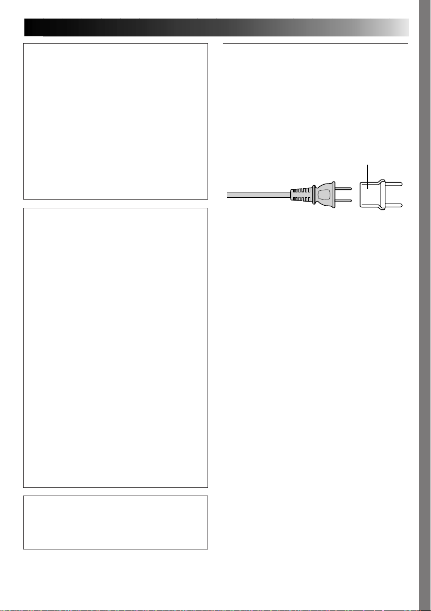
CAUTION (applies to the AA-V68U)
TO PREVENT ELECTRIC SHOCK MATCH WIDE
BLADE OF PLUG TO WIDE SLOT, FULLY
INSERT.
ATTENTION (s’applique à l’AA-V68U)
POUR ÉVITER LES CHOCS ÉLECTRIQUES,
INTRODUIRE LA LAME LA PLUS LARGE DE LA
FICHE DANS LA BORNE CORRESPONDANTE
DE LA PRISE ET POUSSER JUSQU’AU FOND.
NOTES:
●
The rating plate (serial number plate) is on the
bottom and/or the back of the main unit.
●
The rating plate (serial number plate) of the
AC Power Adapter/Charger is on its bottom.
SAFETY
PRECAUTIONS
CAUTION
RISK OF ELECTRIC SHOCK
DO NOT OPEN
CAUTION: TO REDUCE THE RISK OF ELECTRIC SHOCK.
DO NOT REMOVE COVER (OR BACK).
REFER SERVICING TO QUALIFIED SERVICE PERSONNEL.
NO USER-SERVICEABLE PARTS INSIDE.
The lightning flash with arrowhead symbol, within an
equilateral triangle, is intended to alert the user to the
presence of uninsulated "dangerous voltage" within the
product's enclosure that may be of sufficient magnitude
to constitute a risk of electric shock to persons.
The exclamation point within an equilateral triangle is
intended to alert the user to the presence of important
operating and maintenance (servicing) instructions in
the literature accompanying the appliance.
IMPORTANT
䡲 Never use any AC Power Adapter/
Battery Charger other than the one
provided with this printer.
䡲 If you lose the provided AC Power
Adapter/Battery Charger or if it malfunctions, please consult your nearest JVC
service dealer.
This printer is designed to be used with NTSCtype colour television signals. It cannot be used
for monitoring with a television of a different
standard. Use the BN-V607 battery pack and,
to recharge it, the multi-voltage AC Power
Adapter/Charger. (An appropriate conversion
adapter may be necessary to accommodate
different designs of AC outlets in different
countries.)
Page 3

IMPORTANT PRODUCT
SAFETY INSTRUCTIONS
Electrical energy can perform many useful functions. But
improper use can result in potential electrical shock or fire
hazards. This product has been engineered and
manufactured to assure your personal safety. In order not to
defeat the built-in safeguards, observe the following basic
rules for its installation, use and servicing.
ATTENTION:
Follow and obey all warnings and instructions marked on
your product and its operating instructions. For your safety,
please read all the safety and operating instructions before
you operate this product and keep this manual for future
reference.
INSTALLATION
1. Grounding or Polarization
(A) Your product may be equipped with a polarized
alternating-current line plug (a plug having one blade
wider than the other). This plug will fit into the power
outlet only one way. This is a safety feature.
If you are unable to insert the plug fully into the outlet,
try reversing the plug. If the plug should still fail to fit,
contact your electrician to replace your obsolete
outlet. Do not defeat the safety purpose of the
polarized plug.
(B) Your product may be equipped with a 3-wire
grounding-type plug, a plug having a third (grounding)
pin. This plug will only fit into a grounding-type power
outlet. This is a safety feature.
If you are unable to insert the plug into the outlet,
contact your electrician to replace your obsolete
outlet. Do not defeat the safety purpose of the
grounding-type plug.
2. Power Sources
Operate your product only from the type of power source
indicated on the marking label. If you are not sure of the
type of power supply to your home, consult your product
dealer or local power company. If your product is intended
to operate from battery power, or other sources, refer to the
operating instructions.
3. Overloading
Do not overload wall outlets, extension cords, or integral
convenience receptacles as this can result in a risk of fire or
electric shock.
4. Power Cord Protection
Power supply cords should be routed so that they are not
likely to be walked on or pinched by items placed upon or
against them, paying particular attention to cords at plugs,
convenience receptacles, and the point where they exit
from the product.
EN 3
5. Ventilation
Slots and openings in the cabinet are provided for
ventilation. To ensure reliable operation of the product and
to protect it from overheating, these openings must not be
blocked or covered.
•Do not block the openings by placing the product on a
bed, sofa, rug or other similar surface.
•Do not place the product in a built-in installation such as
a bookcase or rack unless proper ventilation is provided
or the manufacturer’s instructions have been adhered to.
6. Wall or Ceiling Mounting
The product should be mounted to a wall or ceiling only as
recommended by the manufacturer.
Page 4

4 EN
USE
1. Accessories
To avoid personal injury:
•Do not place this product on an unstable cart, stand,
tripod, bracket or table. It may fall, causing serious injury
to a child or adult, and serious damage to the product.
•Use only with a cart, stand, tripod, bracket, or table
recommended by the manufacturer or sold with the
product.
•Use a mounting accessory recommended by the
manufacturer and follow the manufacturer’s instructions
for any mounting of the product.
•Do not try to roll a cart with small casters across
thresholds or deep-pile carpets.
2. Product and Cart Combination
A product and cart combination should be moved with
care. Quick stops, excessive force, and uneven surfaces
may cause the product and cart combination to overturn.
3. Water and Moisture
Do not use this product near
water—for example, near a bath
tub, wash bowl, kitchen sink or
laundry tub, in a wet basement, or
near a swimming pool and the
like.
4. Object and Liquid Entry
Never push objects of any kind into this product through
openings as they may touch dangerous voltage points or
short-out parts that could result in a fire or electric shock.
Never spill liquid of any kind on the product.
5. Attachments
Do not use attachments not recommended by the
manufacturer of this product as they may cause hazards.
6. Cleaning
Unplug this product from the wall outlet before cleaning.
Do not use liquid cleaners or aerosol cleaners. Use a damp
cloth for cleaning.
7. Heat
The product should be situated away from heat sources
such as radiators, heat registers, stoves, or other products
(including amplifiers) that produce heat.
PORTABLE CART WARNING
(Symbol provided by RETAC)
SERVICING
1. Servicing
If your product is not operating correctly or exhibits a
marked change in performance and you are unable to
restore normal operation by following the detailed
procedure in its operating instructions, do not attempt to
service it yourself as opening or removing covers may
expose you to dangerous voltage or other hazards. Refer all
servicing to qualified service personnel.
2. Damage Requiring Service
Unplug this product from the wall outlet and refer servicing
to qualified service personnel under the following
conditions:
a. When the power supply cord or plug is damaged.
b. If liquid has been spilled, or objects have fallen into the
product.
c. If the product has been exposed to rain or water.
d. If the product does not operate normally by following
the operating instructions. Adjust only those controls that
are covered by the operating instructions as an improper
adjustment of other controls may result in damage and
will often require extensive work by a qualified
technician to restore the product to its normal operation.
e. If the product has been dropped or damaged in any way.
f. When the product exhibits a distinct change in
performance—this indicates a need for service.
3. Replacement Parts
When replacement parts are required, be sure the service
technician has used replacement parts specified by the
manufacturer or have the same characteristics as the
original part. Unauthorized substitutions may result in fire,
electric shock or other hazards.
4. Safety Check
Upon completion of any service or repairs to this product,
ask the service technician to perform safety checks to
determine that the product is in safe operating condition.
Page 5
CAUTIONS
EN 5
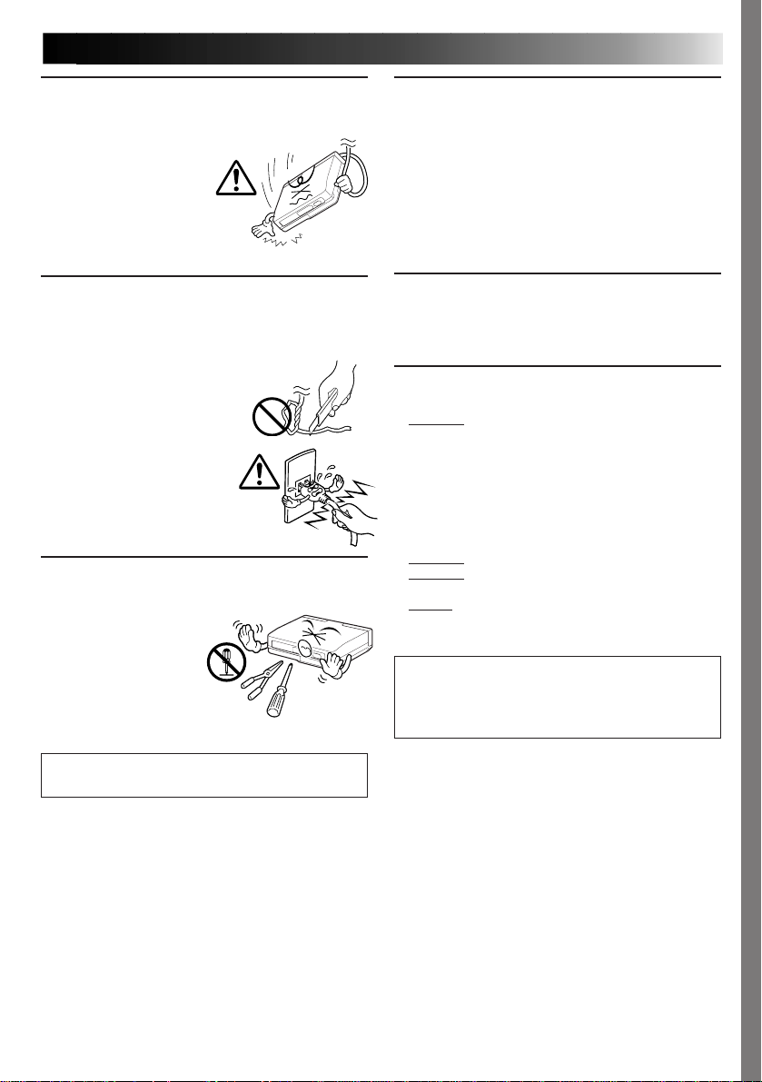
Exercise caution when moving the printer. If you
drop the unit, do not attempt to use it. If during use
you notice that the cabinet
is damaged, shut the
printer down, remove
power supply unit it and
contact your JVC dealer.
Use of the printer under
these conditions can lead
to fire or electric shock.
DO NOT place heavy objects on the AC power
adapters cords, or leave the cord near any heatgenerating appliance, as this can damage the cords.
Avoid excessive pulling or twisting of the power
cords. If the power cords
becomes cut or otherwise
damaged, contact your JVC
dealer. When unplugging the
AC power adapter, DO NOT
pull on the cord. Hold the
plug itself and remove it from
the AC outlet. Use of the
printer with a damaged power
cord can lead to fire, electric
shock and unit malfunctions.
DO NOT remove the cover and attempt to repair or
modify the printer. There are high-voltage
components within the
unit, and the risk of
electric shock and unit
malfunctions exists. If a
problem occurs, contact
your JVC dealer.
ABOUT THERMAL HEADS
•The thermal heads, necessary for printing, are located
within the unit. The heads can become extremely
warm. To prevent possible burns and injuries, do not
touch the thermal heads.
•When the printer is used for extended periods, the
thermal heads experience wear and tear just like VCR
heads. As the thermal heads become worn, print
quality will gradually decrease. When you notice a
decline in quality, it is possible that the heads may
need to be replaced. Consult your JVC dealer.
DUST
Due to dust or lint adhering to print paper, or to
extreme variations in temperature, a small degree of
colour smearing or lines may be visible in prints.
Failure to heed the following precautions may
result in damage to the printer.
1. DO NOT place the printer . . .
... in an environment prone to extreme temperatures
or humidity.
... in direct sunlight.
... in a dusty environment.
... in an environment where strong magnetic fields
are generated.
... on a surface that is unstable or subject to
vibration.
2. DO NOT place heavy objects on the printer.
3. DO NOT place anything which might spill on top of
the printer.
4. AVOID violent shocks to the printer during
transport.
CAUTION:
Changes or modifications not approved by JVC
could void user’s authority to operate the
equipment.
Illustrations of this printer may differ slightly
from production models.
Page 6
6 EN
Battery Packs
The supplied battery pack is a
lithium-ion battery. Before
using the supplied battery pack
or an optional battery pack, be
sure to read the following
cautions:
<Depleting the batteries completely>
1. Turn on the power.
2. Set “power save” to “off” and remove the
batteries when the power is automatically turned
off.
1. To avoid hazard . . .
.... do not burn.
.... do not short-circuit the terminals.
.... do not modify or disassemble.
.... do not expose the battery to temperatures
exceeding 60°C (140°F), as this may cause
the battery to overheat, explode or catch fire.
.... use only specified chargers.
2. To prevent damage and prolong service life . . .
.... do not subject to unnecessary shock.
.... charge in an environment where tempera-
tures are within the tolerances shown in the
chart below. This is a chemical reaction type
battery—cooler temperatures impede
chemical reaction, while warmer temperatures can prevent complete charging.
.... store in a cool, dry place. Extended exposure
to high temperatures will increase natural
discharge and shorten service life.
.... fully charge and then fully discharge the
battery once a year when storing the battery
pack over a long period time.
.... remove from charger or powered unit when
not in use, as some machines use current
even when switched off.
NOTES:
●
It is normal for the battery pack to be warm after
charging, or after use.
Temperature Range Specifications
Charging .................10°C to 35°C (50°F to 95°F)
Operation ............... 0°C to 40°C (32°F to 104°F)
Storage ................... –10°C to 30°C (14°F to 86°F)
●
Recharging time is based on room temperature of
20°C (68°F).
●
The lower the temperature, the longer recharging
takes.
Terminals
CAUTIONS
About Batteries
DANGER! Do not attempt to take the batteries
apart, or expose them to flame or excessive heat, as
there is a risk of fire or explosion.
WARNING! Do not allow the battery terminals, or
the battery itself, to come in contact with metals, as
this can result in a short circuit and possibly start a
fire.
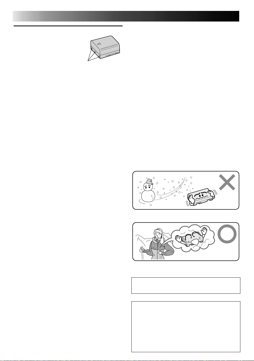
The Benefits Of Lithium-Ion Batteries
Lithium-ion battery packs are small but possess a
large power capacity. However, when the battery
pack becomes cool in an environment subject to
cold temperatures (below 10°C (50˚F)), the battery
pack has a characteristic that its usage time
becomes shorter and may cease to function. If this
happens, place the battery pack in your pocket or
other warm, protected place for a short time, then
re-attach it to the camcorder. As long as the battery
pack itself is not cold, it should not affect performance.
(If you’re using some kind of heating pad, make
sure the battery pack does not come in direct
contact with the pad.)
Lithium-ion is vulnerable in colder temperatures.
Serious malfunctioning
If malfunctioning occurs, stop using the unit
immediately and consult your local JVC dealer.
The printer is a microcomputer-controlled
device. External noise and interference (from a
TV, a radio, etc.) might prevent it from functioning properly. In such cases, first disconnect its
power supply unit (battery pack, AC Power
Adapter/Battery Charger, etc.) and then reconnect it and proceed as usual from the
beginning.
Page 7
EN 7
Declaration of Conformity
Model Number : GV-HT1U
Trade Name : JVC
Responsible party : US JVC CORP.
Address : 41 Slater Drive,
Elmwood Park, N. J.
07407
Telephone Number : (201) 794–3900
This device complies with Part 15 of FCC Rules.
Operation is subject to the following two
conditions:
(1) This device may not cause harmful
interference, and (2) this device must accept
any interference received, including interference that may cause undesired operation.
Change or modifications not approved by the
party responsible for compliance could void the
user’s authority to operate the equipment. This
equipment has been tested and found to
comply with the limits for a Class B digital
device, pursuant to Part 15 of the FCC Rules.
These limits are designed to provide reasonable
protection against harmful interference in a
residential installation. This equipment
generates, uses, and can radiate radio frequency
energy and, if not installed and used in
accordance with the instructions, may cause
harmful interference to radio communications.
However, there is no guarantee that interference
will not occur in a particular installation. If this
equipment does cause harmful interference to
radio or television reception, which can be
determined by turning the equipment off and
on, the user is encouraged to try to correct the
interference by one or more of the following
measures:
Reorient or relocate the receiving antenna.
Increase the separation between the equipment and receiver.
Connect the equipment into an outlet on a
circuit different from that to which the
receiver is connected.
Consult the dealer or an experienced radio/
TV technician for help.
This Class B digital apparatus complies with
Canadian ICES-003.
Cet appareil numérique de la classe B est
conforme à la norme NMB-003 du Canada.
When using the AC Power Adapter/Charger in
areas other than the USA
䡲 The provided AC Power Adapter/Charger features
automatic voltage selection in the AC range from
110 V to 240 V.
USING HOUSEHOLD AC PLUG ADAPTER
In case of connecting the unit’s power cord to an
AC wall outlet other than American National
Standard C73 series type use an AC plug adapter,
called a “Siemens Plug”, as shown.
For this AC plug adapter, consult your nearest JVC
dealer.
Plug adapter
•This printer uses the following program
under license from Okaya Systemware Co.,
Ltd. for IrDA infrared transmission:
TM
IrDA Protocol Stack “Deep Core
” Okaya
Systemware Co., Ltd.
NOTICE
Copyright
Use of images imported from television broadcasts
and recorded materials for other than personal
enjoyment without permission from the copyright
owner constitutes an infringement on applicable
copyright laws.
Sample Images
The sample images supplied with this printer are
used under license from Kodak Japan Co., Ltd. who
is the copyright owner.
The image samples provided with this printer are
Photo CD images from the Kodak Photo CD
Sampler with FILM that were processed as
described below using Adobe Photoshop 3.0J.
<Sample Image Data>
The original 768 x 512 image was trimmed to 598 x
448 and compressed using the JPEG format before
recording.
<Source of Images>
Kodak Photo CD Sampler with FILM No. 2
“Marine” 18
Note:
•Note that prints of camcorder or Digital Still
Camera images will not be as sharp as prints of
the sample images.
•Company names and product names mentioned in
this manual are the logos or registered trademarks
of respective company.
Page 8
8 EN
This equipment is a portable printer that is light enough to bring along with a camcorder or
digital still camera on a trip or outing.
It can be used in a wide variety of applications.
MAJOR FEA TURES
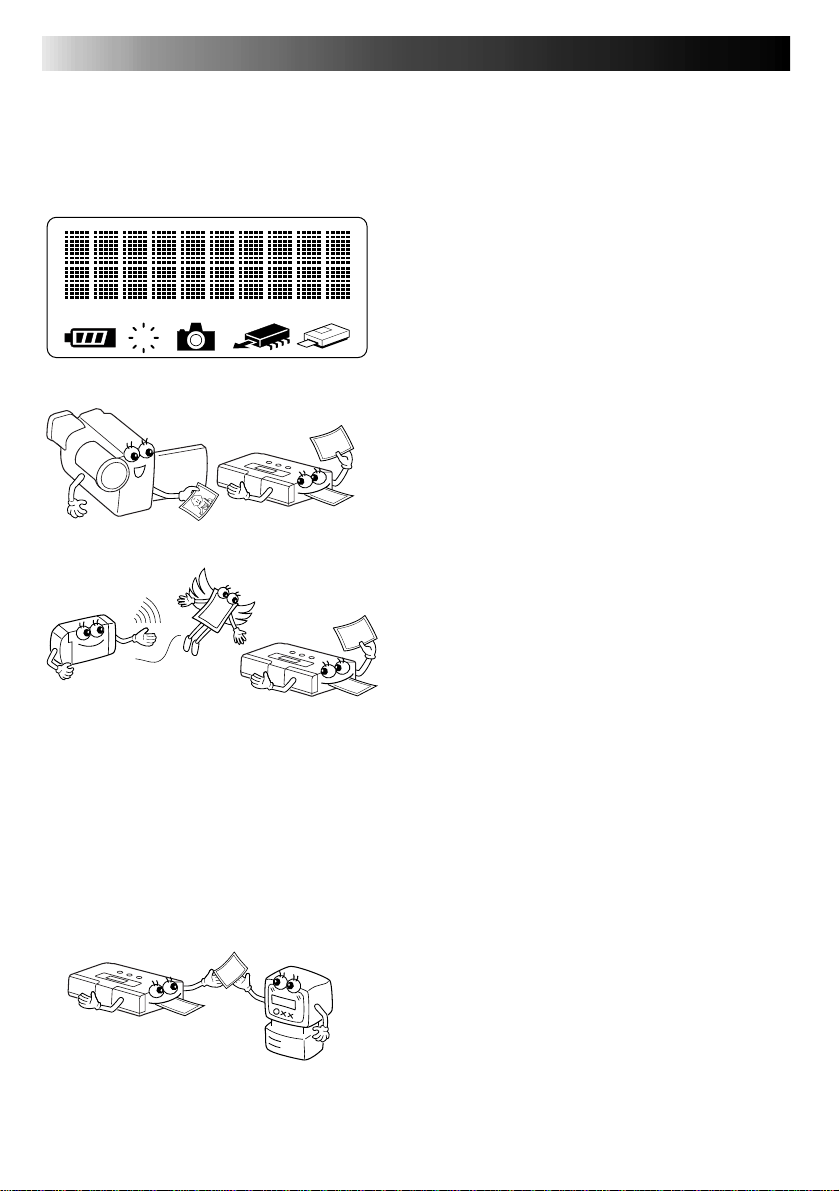
Easy to read LCD Display
The messages and icons displayed on the LCD
panel show at a glance the operating state of the
printer.
E
Printing from Camcorder
Any camcorder with an output terminal can be
connected to the printer for instant printing of the
desired photo anywhere.
Cordless connection to digital still
cameras
This printer offers cordless connection to any
digital still camera conforming to the infrared
image transmission (IrTran-P) standard.
Battery powered for portable
operation
Load the battery and you are ready to provide your
friends with instant printouts of pictures taken at
parties or outdoors.
Input for PC Connection
Used with optional software, this printer connects
to a Windows® PC communications port (RS-232C)
or Macintosh communications port
(RS-422) for printing images.
Page 9
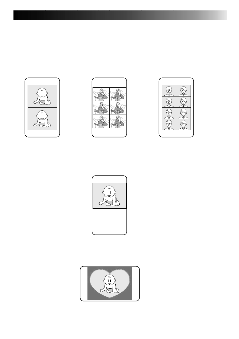
You can print the picture of your choice on standard paper, stickers.
A number of special effects are available in addition to normal printing.
Multipix
On a page you can print 2, 6 or 8 images.
Calendar Printing
You can use pictures of your choice to print your own calendar.
EN 9
12 1998
SUN MON TUE WED THU FRI SAT
12345
6789101112
13 14 15 16 17 18 19
20 21 22 23 24 25 26
27 28 29 30 31
Frame Print
Internal frames can be superimposed on an image for printing stickers.
Page 10

10 EN
CAUTIONS
CONTENTS
5
MAJOR FEATURES
CONTROLS, INDICATORS AND CONNECTORS
Front View ....................................................................................12
Rear View .....................................................................................13
Bottom View ..................................................................................13
Operation buttons ............................................................................14
Memory and Print Operations ..............................................................14
Selecting and setting menu items ..........................................................14
Menu Setting List.............................................................................15
CONNECTIONS (Video Connections)
Printing from source with video output terminals .......................................16
CONNECTIONS (IrDA Reception)
Printing from a digital still camera with IrTran-P ........................................17
SUPPL YING THE POWER
Charging the Battery.........................................................................18
Loading the Battery ..........................................................................19
Using AC power ..............................................................................19
INSTALLATION OF INK CASSETTE
Installing the Ink cassette...................................................................20
8
12
16
17
18
20
LOADING THE BLANK PAPER
Loading Blank Paper .........................................................................22
PREPARATION
PRINTING FROM VIDEO SOURCE WITH VIDEO TERMINALS
PRINTING FROM IrTran-P EQUIPPED DIGITAL STILL CAMERA
MISCELLANEOUS PRINTING OPERATIONS
Superimposing the Frame of Choice on the Image – Frame Printing – ................28
Printing Multiple Images on the Same Paper – MULTI Print – .........................30
Combining Image and Calendar – Calendar Printing –...................................32
Printing Using Special Effects – Special Effects – ........................................34
Manual Feed ..................................................................................36
Printing Reversed Images – Mirror Images – ............................................38
22
23
24
26
28
Page 11
ADJUSTMENTS
Adjusting Image Quality – Adjustments before Printing –..............................39
Saving Energy – Power Save – ............................................................40
Switching between Moving Picture and Still Picture – Memory Mode Selections –
EN 11
39
...41
TROUBLESHOOTING
PRINTING FROM THE PERSONAL COMPUTER
SPECIFICATIONS
INDEX
FOR SERVICING (Only in U.S.A.)
WARRANTY (Only in U.S.A.)
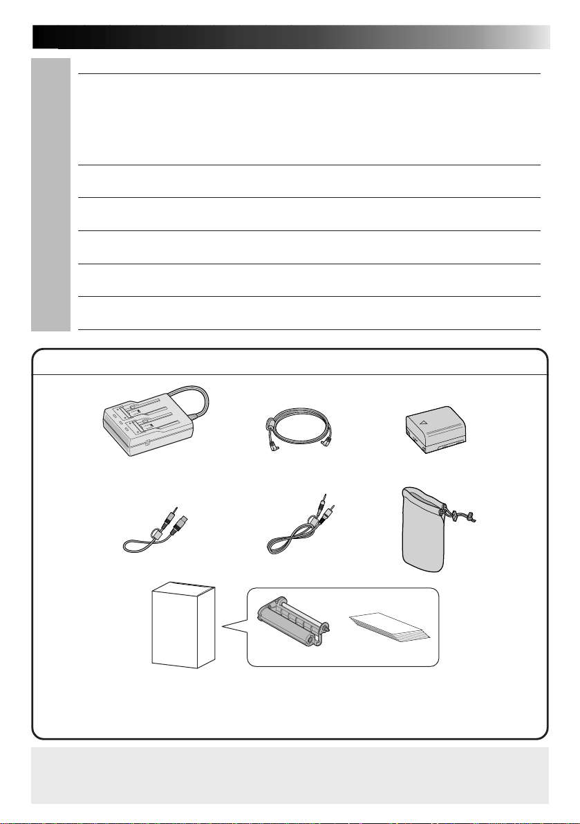
PROVIDED ACCESSORIES
approx. 0.8 m
42
45
46
47
48
49
Battery Pack BN-V607AC adapter/Charger AA-V68 DC cord,
Soft caseVideo cable 1 Video cable 2
Ink cassette
Blank Paper Sheet Set
•Standard Print Paper (6 sheets)
•Sticker paper (6 sheets)
•Ink Cassette (12 prints)
It should be noted that it may be unlawful to print from pre-recorded tapes or discs without
the consent of the owner of copyright in the video recording, broadcast or cable programme
and in any literary, dramatic, musical, or artistic work embodied therein.
Printing paper
Page 12
12 EN
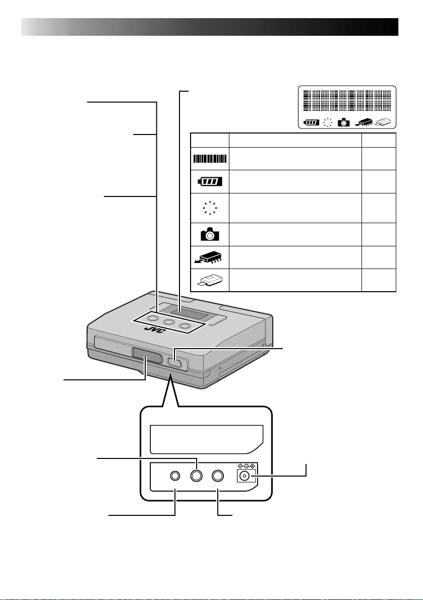
CONTROLS, INDICATORS AND CONNECTORS
Front View
MENU Button
Turns menu items on and off.
MEMORY/SELECT Button
MEMORY Button
Press to store an input image.
SELECT Button
Selects menu items.
PRINT/SET Button
PRINT Button
Press this button after storing an
image to print it.
SET Button
Press to change setup items.
LCD Panel
Displays messages and icons
during operation to indicate
printer operating status.
Display Function See page
Message field
Indicates menu settings and printer status.
Indicates remaining battery power.
Lights when a print error has occurred.
The message field indicates the nature of
E
the error.
Lights when still image memory mode
has been selected.
Lights to indicate that an image has been
stored in the printer.
Lights during printing.
E
15, 42
43
41
25
25
–
IrTran-P
(IrDA receiving window)
Receives image data during
infrared transmission.
Jack cover
Video input jack
Connects a video cable from
the video output terminal on
camcorder or other unit.
PC IN OUT DC IN
PC connection jack
With the use of optional software, the printer
can be connected to a communications port
on a PC compatible (RS-232C) or Macintosh
(RS-422).
POWER Button
Turns the printer on and off.
DC IN
Connects AC Adapter/Charger
by using a DC cord (provided).
Video output jack
· Outputs input image or print image for view ing on a TV or other monitor.
· Connect this output to a video input terminal
on a TV.
Page 13
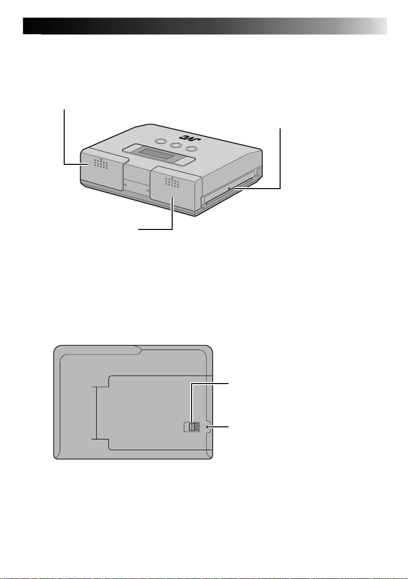
Rear View
EN 13
Battery compartment
Open the lid to load or remove battery.
Ink cassette compartment
Open the lid to load or remove ink cassette.
Bottom View
Paper out/manual feed slot
· Finished prints are ejected from this exit.
· Single sheets of paper are inserted here
during manual feed.
Paper compartment door switch
Slide this switch to open the paper
compartment.
Paper compartment door
Open this door to load paper.
Page 14
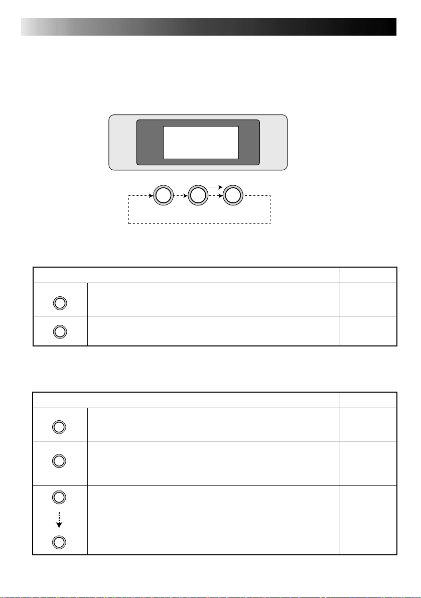
14 EN
CONTROLS, INDICATORS AND CONNECTORS (Continued)
䢇Operation buttons
Use these buttons to perform operations from storing to printing images, selecting and setting
menu items.
Use the buttons and follow the instructions given on the LCD panel.
MENU
MEMORY
SELECT
PRINT
SET
䢇Memory and Print Operations
Mode overview
MEMORY
PRINT
Press to store input video image.
·
Press to print stored video image.
·
䢇Selecting and setting menu items
Mode overview
MENU
SELECT
·
Turns menus on and off.
·
Press once to select a menu.
·
Each press of the SELECT button displays a menu item on the
LCD panel.
·
Select desired item.
See page
25
25
See page
24
24
SET
MENU
·
Press the SET button and the Selected mode indicator blinks.
·
Each press of the SET button changes the blinking item on the
LCD panel. Select the desired item.
·
Press the MENU button after selecting the desired item with
the SET button to confirm the selection.
24
Page 15
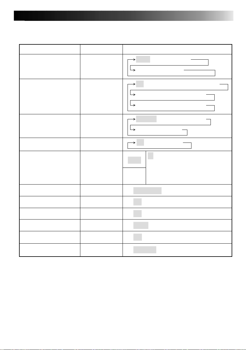
䢇Menu Setting List
Set video source
· Print sample
· Superimpose frame list
input
EN 15
SettingDesired Action Menu item
video → infrared → PC
sample → frame list
Superimpose frame
Enter print mode
Add special print effect
Adjust brightness or tint
· adjust before storing the
image
Suppress blur
Manual feed print
Print mirror image
Save energy
Remove jammed paper
Switch monitor display monitor
frame set.
print mode
effect
adj. image
mem. mode
man. feed
mirror
power save
form feed
off → frame 1 → frame 2 → frame 3
frame 4 → frame 5 → frame 6
frame 7 → frame 8 → frame 9
standard → multi-2 → multi-6
multi-8 → calendar
off → sepia → B/W
0
tint
+1, +2, +3, +4, +5
–1, –2, –3, –4, –5
bright.
moving pic ↔ still pic
off ↔ on
off ↔ on
5min. ↔ off
off ↔ on
input pic. ↔ mem. pic.
• Initial settings are indicated in gray.
The printer returns to these settings when powered up after shutdown.
• Menu items that cannot be selected are not displayed.
• A sample video image is stored in the printer. You can select “sample” to print out this
sample in the “input” menu.
Page 16
16 EN
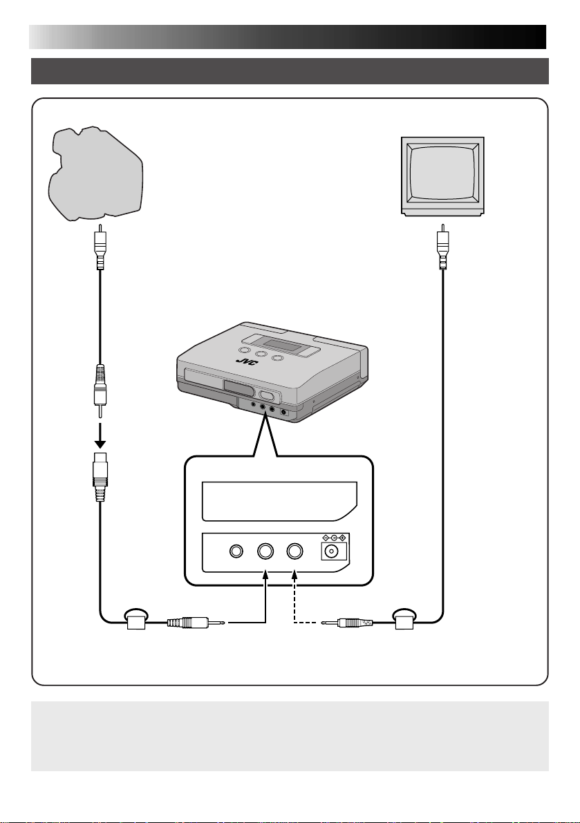
CONNECTIONS (Video Connections)
Printing from source with video output terminals
TVVIDEO Source
Connect to video
output terminals
(yellow)
Video cable
(Supplied with a video
source or optional)
(yellow)
(black)
Video cable 1
(Provided)
Jack cover
(black) (yellow)
Connect to video
input terminal
(yellow)
Video cable 2
(Provided)
PC IN OUT DC IN
Connect to video
IN jack
Notes:•Make sure that the printer is properly connected to the video source. A loose video
cable connection will prevent printing.
•Do not place the printer on its side or on a leaning surface as this may cause paper
jams.
Connect to video
OUT jack
Page 17

CONNECTIONS (IrDA Reception)
Printing from a Digital Still Camera with IrTran-P
This is a standard for transmitting data using infrared
transmission. Equipment that conform to this standard
can transmit to each other regardless of make.
Digital still camera
with IrTran-P
Approx. 15˚ Approx. 15˚
Up to 1.6 ft (50 cm)
The distance at which
transmission is possible
varies with the equipment
used.
Printer
EN 17
IrDA receiver
Notes:• IrDA infrared communications allow only two pieces of equipment to communicate.
Transmission from one digital still camera to several printers simultaneously is not
possible. Only the printer that first receives the data can print it.
•Transmission may become unstable or impossible due to external light, the state of
battery depletion and the distance or angle between the equipment.
Page 18

18 EN
SUPPL YING THE POWER
Charging the battery
Use the provided AA-V68 AC adapter/Charger for charging the battery. Batteries that have not
been completely depleted can also be charged.
1
To AC outlet
Charge
indicator 1
Power lamp
Charge indicator 2
(Blinks during charging → Lights continuously when charging completes.)
Place side with
and symbols
face down.
Battery BN-V607
2
Power cord
AC Adapter/Charger
AA-V68
DC output terminal
CONNECT AC ADAPTER/CHARGER
1
•Connect the power cord to a wall outlet.
INSERT THE BATTERY
2
•The charge indicator starts to blink.
•Charging has completed when the indicator
REMOVE THE BATTERY
3
•Remove the power cord.
stops blinking and is on continuously.
3
•Approximate charge time → Approx. 90 min for each BN-V607 battery
•Charging not possible → Charging is not possible when the DC cord is
•Number of prints per battery charge → 40 prints for each BN-V607 battery (at room
:
NOTES
•If you connect the DC cord to the AC adapter during battery charging, power is supplied to the printer
and charging stops.
•When charging the Battery for the first time or after a long storage period, the Charger Indicator may not
light. In this case, remove the Battery from the AC Power Adapter then try charging again.
•Since the AC Power Adapter processes electricity internally, it becomes warm during use. Be sure to use
it only in well-ventilated areas.
•If the battery operation time remains extremely short even after having been fully charged, the battery is
worn out and needs to be replaced. Please purchase a new one.
connected to the AC adapter.
temperature)
Page 19

EN 19
2
Loading the Battery
The battery (BN-V607) is not charged when
shipped.
Charge it using the AC adapter before use.
1, 3
OPEN THE BATTERY COMPART-
1
MENT LID
•Slide and open the battery compartment
lid in the direction of the arrow.
INSERT THE CHARGED BATTERY
2
•Note that the battery may be damaged if
it is inserted
incorrectly.
•Slide in the battery as far as it will go
until it is properly seated.
Using AC power
When using the printer indoors, you can use
the AC Adapter instead of a battery.
DC IN
Jack
To
AC outlet
DC IN
2
1
DC cord
Power lamp
CONNECT DC CORD
1
•Connect the DC cord to the AC Adapter
then to the printer.
SUPPLY AC POWER
2
•Connect the power cord to an AC outlet.
CLOSE THE BATTERY COMPART-
3
MENT LID
Removing the Battery
•Open the battery compartment lid and take
out the battery.
NOTE:
When using the provided DC cord, make
sure you connect the end of the cable with
the core filter to the printer. The core filter
reduces the interference.
Page 20

20 EN
3
Installing the Ink cassette
Before printing, load printing paper and ink kit as shown below.
INST ALLA TION OF INK C ASSETTE
1, 4
OPENING INK CASSETTE COM-
1
INK
PARTMENT LID
•To open the ink cassette compartment lid,
slide it in the direction of the arrow as far as
it will go.
2
REMOVING SLACK IN THE INK
2
RIBBON, IF ANY
•Insert a ball-point pen or the like and rotate
the roller in the indicated direction.
INSTALLING INK CASSETTE
3
•Hold the side with model label face up and
slide in the ink cassette as far as it will go.
CLOSE THE INK CASSETTE COM-
4
PARTMENT LID
When removing ink cassette
•Grasp the knob at the center of the ink cassette and
pull it towards you.
CAUTION:
Do not touch the inside of the ink cassette
compartment to avoid burns and other injuries.
Page 21

About blank Paper sheet Set (optional)
One of the following accessories is required in printing with this printer.
EN 21
SET
PV-C20AU
(Standard type)
PV-C12SAU
(Sticker type)
PV-C12KAU
(Standard type,
Sticker type)
Note: Pay attention to the following in handling printing paper and ink cassettes
CONTENTS
Standard paper: 20 sheets
Ink cassette (20 prints)
Sticker paper: 12 sheets
Ink cassette (12 prints)
Standard paper: 6 sheets
Sticker paper: 6 sheets
Ink cassette (12 prints)
USES
To print the scene of your choice to
make commemorative shots.
Make personalized stickers for
pasting on cards, etc.
Make personalized stickers for
pasting on cards, etc.
Before printing
•Do not use printing paper that has been folded or curled to avoid paper jams.
•Do not use wet or humid printing paper as it will not print normally and could cause a paper
jam.
•Do not touch or write on the print surface.
•Do not touch or pull out the ink sheets in the ink cassette.
•Make sure that children do not lick or ingest the ink sheets.
•Used ink cassettes should be replaced with new cartridges.
Old cartridges cannot be reused. Do not attempt to reuse the cartridge by rewinding the
rollers.
•Printing paper and ink cassettes must not be stored in a location exposed to high
temperatures, high humidity or directsunlight.
•Read the instructions accompanying the printing paper and ink cassette and use them
accordingly.
After printing
•The printer applies a coating to make the prints glossy.
•The prints should be handled with care since they are coated with a soft material that can
easily be damaged by sharp objects such as a fingernail or the like.
•The colors will fade if the paper is exposed to volatile solvents (alcohol, toluene, ketone,
etc.).
•Do not paste adhesive tape on the print surface. The image will be damaged when the tape
is removed.
Care in storing prints
•Printed paper must not be stored in a location exposed to high temperatures, high humidity
or direct sunlight.
•Store printing paper horizontally in the box. If stored vertically, the paper might curl and
cause paper jams.
Page 22

22 EN
Loading Blank Paper
To print, load Blank paper sheet set.
1, 3 2
LOADING THE BLANK PAPER
OPEN
OPEN
A
Notes:
· Make sure that the paper does not
rise above tab .
· Place the side with the text face up.
· Number of sheets: max. 15 sheets
A
Printing surface
(white side)
OPEN PAPER COMPARTMENT
1
DOOR
•Slide the paper compartment door switch in
the direction of the arrow to open the paper
compartment door.
LOAD BLANK PAPER
2
•Riffle through the paper so that each sheet is
separated from the next and place it with the
printing surface (white side) facing inside.
•Make sure that the paper does not rise above
tab A .
CLOSE THE PAPER COMPARTMENT
3
DOOR
•Make sure that the paper has been correctly
loaded.
•The door clicks into place when the door is
properly closed.
Notes:•Read the instructions on the printing paper and ink kit, and the “Caution on Loading
Printing Paper” on the inside of the printing paper compartment.
•Loading printing paper
Since the paper cannot be properly fed if each sheet sticks together, riffle through the
paper before loading it and make sure that the paper ends are aligned.
If the message, “Insert paper” is displayed when there is paper in the paper
compartment, reload the paper.
Page 23

PREP ARA TION
䢇 Before printing, make sure everything is set up and ready.
1. Connect the printer to the video source to be
printed from. (墌pg. 16).
•To use IrTran-P, transmit the images after turning on the power as described in step 5.
2. Have a Blank Paper Sheet Set ready (墌pg. 21).
3. Install the ink cassette in the printer (墌pg. 20).
4. Open the paper compartment door and place the
printing paper (墌pg. 22).
•Use the printing paper in the same box as the ink cassette.
EN 23
5. Turn on the power. (墌pg. 12).
•Insert the power plug of the AC adapter in a wall outlet.
•The printer can also be battery powered.
•Turn on the printer.
Notes:
•The above completes all printer preparations.
•Please read the instructions on pages 24 to 41 before printing.
Page 24

24 EN
MEMORY
SELECT
Y
PRINT
SET
This is the standard method for printing from a video source with video terminals. It allo ws y ou to
easily connect your Camcorder, VCR or other video source with video terminals to the printer.
PRINTING FROM VIDEO SOURCE WITH VIDEO TERMINALS
67
MEMORY
MENU
SELECT
MENU
PRINT
SET
21, 4 3
i
nput
video
LCD panel
Preparations
•Make the connections (墌pg. 16).
Selecting Menu Item
PRESS THE MENU BUTTON
1
•This action displays the printer menu on the
LCD panel.
PRESS THE SELECT BUTTON
2
•Press the SELECT button repeatedly until
“input” appears.
MENU
i
nput
Video
Note:
When “video” is already displayed on the
LCD panel, press the MENU button and skip
steps 3 and 4.
PRESS THE SET BUTTON
3
•The item on the second line of the LCD
panel starts to flash.
•Press the SET button until “video” appears.
PRESS THE MENU BUTTON TWICE
4
TO CONFIRM THE ENTRY
Page 25

MENU
MEMORY
SELECT
PRINT
SET
Print Operations
SET THE VIDEO SOURCE TO PLAY-
5
BACK MODE
•For details, refer to the instruction manual
supplied with the video source.
PRESS THE MEMORY BUTTON
6
WHEN THE IMAGE YOU WISH TO
PRINT APPEARS
•This action stores the image you wish to print.
•The message, “Please wait ...” is displayed
on the LCD panel while the image is being
stored. The message, “Store in memory” is
displayed when the image has been stored.
•The memory icon
following conditions.
on: image data has been stored in the printer
off: no image data is stored in the printer
indicates the
EN 25
MENU
MEMORY
SELECT
PRINT
SET
PRESS THE PRINT BUTTON
7
•The printer starts printing the stored image.
•The message, “Please wait ...” is displayed
on the LCD.
Then the printer icon
appears.
•The printer icon indicates the
following conditions.
on: image data is being printed
off: printing has been completed
•When printing is completed, the message,
“Remove paper” is displayed on the LCD
panel.
Do not touch the printer or printing paper
until this message is displayed.
NOTES:
•To print the same image again, press the PRINT button. One print is made each time the
PRINT button is pressed.
•To print a different image, perform operations in steps 5 to 7.
•To store the picture again before printing, switch menu item “monitor” from “mem. pic” to
“input pic.”
•Do not touch the printer or the paper during printing
During printing paper will come out of the paper out/manual feed slot; do not touch the
paper until printing stops to prevent paper jams.
Do not open the paper compartment door or the ink cassette compartment lid during
printing. When the printer is battery powered, do not open the battery compartment door. If
opened, printing stops and the power is automatically turned off. When the printer is
powered up again, the paper that was being printed when printing stopped is ejected.
Page 26

26 EN
MEMORY
SELECT
Y
PRINT
SET
The printer can receive and print images from an IrTran-P equipped digital still camera. Since no
cables are required, this printing method is ideal at wedding receptions, parties or the like.
PRINTING FROM IrTran-P EQUIPPED DIGITAL STILL CAMERA
78
MEMORY
MENU
SELECT
Preparations
•Make the connections (墌pg. 17).
•Place the digital still camera and printer within a 1.6 ft (50 cm) distance of each other. Image
transmission can be performed within a 15° angle of the printer receiving window.
•Read the instructions in the instruction manual supplied with the IrTran-P equipped digital still
camera.
PRINT
SET
21, 4 3
IrDA receiving window
Selecting Menu Item
MENU
PRESS THE MENU BUTTON
1
•This action displays the printer menu on the
LCD panel.
PRESS THE SELECT BUTTON
input
video
2
•Press the SELECT button repeatedly until
“input” appears.
MENU
i
nput
rfniared
PRESS THE SET BUTTON
3
•The item on the second line of the LCD
panel starts to blink.
•Press the SET button until “infrared” appears.
PRESS THE MENU BUTTON TWICE
4
TO CONFIRM THE ENTRY
Page 27

Note:
Transmission may become unstable or
impossible due to external light, the
state of battery depletion and the
distance or angle between the
equipment.
Digital Still Camera Operations
SELECT THE DIGITAL STILL CAMERA
5
IMAGE YOU WISH TO PRINT
•For details, refer to the instruction manual
supplied with the camera.
TRANSFER THE CAMERA IMAGE TO
6
THE PRINTER
•Orient the infrared sending window on the
digital still camera so that it faces the IrTran-P
receiving window on the printer.
•Make sure that there are no objects between
the printer and the camera.
•Transmit the data from the camera to the
printer.
EN 27
MEMORY
SELECT
PRINT
SET
MENU
NOTES:
•To print the same image again, press
the PRINT button. One print is made
each time the PRINT button is
pressed.
•To print a different image, press the
MEMORY button to clear the stored
image and perform operations in
steps 5 to 8.
Print Operations
THE PRINTER STARTS RECEIVING
7
THE IMAGE
•The image you wish to print is now being
stored.
•While the image data is being stored, the
message, “infrared receiving” is displayed on
the LCD panel.
•The memory icon
following conditions.
on: image data has been stored in the printer
off: no image data is stored in the printer
indicates the
PRESS THE PRINT BUTTON
8
•The printer starts printing the stored image.
•The message, “Please wait ...” is displayed
on the LCD panel.
Then the printer icon
•The printer icon
following conditions.
on: image data is being printed
off: printing has been completed
appears.
indicates the
Page 28

28 EN
MEMORY
SELECT
Y
PRINT
SET
MISCELLANEOUS PRINTING OPERA TIONS
Superimposing the Frame of Choice on the Image – Frame Printing –
•You can print a frame around an image.
•Select one frame you wish to use out of the nine available frames. You can use sticker paper to
print titles for greeting cards and so on.
67
MENU
MENU
MEMORY
SELECT
PRINT
SET
21, 4 3
frame set
off
f
r ame s e t
r
f ame
Preparations
•Make the connections (墌pg. 16).
Selecting Menu Item
PRESS THE MENU BUTTON
1
•This action displays the printer menu on the
LCD panel.
.
PRESS THE SELECT BUTTON
2
•Press the SELECT button repeatedly until
“frame set.” appears.
PRESS THE SET BUTTON
3
•The item on the second line of the LCD
.
7
panel starts to blinking.
•Press the SET button until the desired frame
number appears.
MENU
PRESS THE MENU BUTTON TWICE
4
TO CONFIRM THE ENTRY
Page 29

MENU
MEMORY
SELECT
PRINT
SET
Print Operations
SET THE VIDEO SOURCE TO PLAY-
5
BACK MODE
•For details, refer to the instruction manual
supplied with the video source.
PRESS THE MEMORY BUTTON
6
WHEN THE IMAGE YOU WISH TO
PRINT APPEARS
•This action stores the image you wish to print.
•The message, “Please wait ...” is displayed
on the LCD panel while the image is being
stored.
•The memory icon
following conditions.
on: image data has been stored in the printer
off: no image data is stored in the printer
indicates the
EN 29
MENU
MEMORY
SELECT
PRINT
SET
PRESS THE PRINT BUTTON
7
•The printer starts printing the stored image.
•The message, “Please wait ...” is displayed
on the LCD panel.
Then the printer icon
•The printer icon
following conditions.
on: image data is being printed
off: printing has been completed
NOTES:
•To print the same image again, press the PRINT
button. One print is made each time the PRINT
button is pressed.
•To print a different image, perform operations in
5
to 7.
steps
•The frame cannot be changed after printing.
•When the “input” menu item is displayed (see
page 15), you can select “frame list” and print
all 9 frames. This makes it easier to select a
frame.
appears.
indicates the
Page 30

30 EN
MEMORY
SELECT
Y
PRINT
SET
MISCELLANEOUS PRINTING OPERA TIONS (Cont.)
Printing Multiple Images on the Same Paper – MULTI Print –
You can print 2, 6 or up to 8 images on a single paper.
This makes it easy to customize printing to suit the application.
You can use sticker paper to print titles for season's greetings and so on.
67
MENU
MENU
MEMORY
SELECT
21, 4 3
p
rin m
p
rint
m
ulti
PRINT
SET
t
ardstand
ode
mode
2-
Preparations
•Make the connections (墌pg. 16).
Selecting Menu Item
PRESS THE MENU BUTTON
1
•This action displays the printer menu on the
LCD panel.
PRESS THE SELECT BUTTON
2
•Press the SELECT button repeatedly until
“print mode” appears.
PRESS THE SET BUTTON
3
•The item on the second line of the LCD
panel starts to blink.
•Press the SET button until the desired number
of images appears.
MENU
PRESS THE MENU BUTTON TWICE
4
TO CONFIRM THE ENTRY
Page 31

MENU
MENU
MEMORY
SELECT
MEMORY
SELECT
PRINT
SET
PRINT
SET
Print Operations
SET THE VIDEO SOURCE TO PLAY-
5
BACK MODE
•For details, refer to the instruction manual
supplied with the video source.
PRESS THE MEMORY BUTTON
6
WHEN THE IMAGE YOU WISH TO
PRINT APPEARS
•This action stores the image you wish to print.
•The image stored in memory is displayed in
the selected number of multiple images.
•The message, “Please wait ...” is displayed
on the LCD panel while the image is being
stored.
•The memory icon
indicates the
following conditions.
on: image data has been stored in the printer
off: no image data is stored in the printer
PRESS THE PRINT BUTTON
7
•The printer starts printing the stored image.
•The message, “Please wait ...” is displayed
on the LCD panel. Then the printer icon
appears.
•The printer icon
following conditions.
on: image data is being printed
off: printing has been completed
indicates the
EN 31
NOTES:
•To print the same image again, press the
PRINT button. One print is made each time
the PRINT button is pressed.
•To print a different image, perform operations
5
in steps
to 7.
•The multipix setting cannot be changed after
printing.
•On a TV screen, multipix images are displayed
horizontally across the screen.
Page 32

32 EN
MEMORY
SELECT
Y
PRINT
SET
MISCELLANEOUS PRINTING OPERA TIONS (Cont.)
Combining Image and Calendar – Calendar Printing –
You can turn your favorite picture into a calendar.
67
MEMORY
MENU
SELECT
2,31,4 3
MENU
PRINT
SET
prin modet
standard
Month
1 : January
2 : February
3 : March
4 : April
5:May
6 : June
7 : July
8 : August
9 : September
10 : October
11 : November
12 : December
12 1998
SUN MON TUE WED THU FRI SAT
12345
6789101112
13 14 15 16 17 18 19
20 21 22 23 24 25 26
27 28 29 30 31
Preparations
•Make the connections (墌pg. 16).
Selecting Menu Item
PRESS THE MENU BUTTON
1
•This action displays the printer menu on the
LCD panel.
PRESS THE SELECT BUTTON
2
•Press the SELECT button repeatedly until
“print mode” appears.
Year
prin modet
calendar
year 1998
mon t h 1
year
9981
12month
PRESS THE SET BUTTON
3
•The item on the second line of the LCD panel
starts to blink.
•Press the SET button until the “calendar”
appears on the LCD panel.
•Do as follows to change calendar years and
months.
· Press the SELECT button when “calendar”
blinks.
· Press the SET button repeatedly until the
desired year appears on the LCD panel. Years
between 1998 and 2007 can be selected.
· Press the SELECT button.
· Press the SET button repeatedly until the
desired month appears on the LCD panel.
The months are displayed on the LCD panel as
the figures 1 to 12 (for January to December).
· Press the MENU button to confirm the entry.
Page 33

EN 33
MENU
MENU
MENU
MEMORY
SELECT
MEMORY
SELECT
PRINT
SET
PRINT
SET
PRESS THE MENU BUTTON TWICE
4
TO CONFIRM THE ENTRY
•When entering the year and month in step 3,
press the MENU button only once.
Print Operations
SET THE VIDEO SOURCE TO PLAY-
5
BACK MODE
•For details, refer to the supplied instruction
manual.
PRESS THE MEMORY BUTTON
6
WHEN THE IMAGE YOU WISH TO
PRINT APPEARS
•This action stores the image you wish to print.
•The message, “Please wait ...” is displayed
on the LCD panel while the image is being
stored.
•The memory icon
following conditions.
on: image data has been stored in the printer
off: no image data is stored in the printer
indicates the
PRESS THE PRINT BUTTON
7
•The printer starts printing the stored image.
•he message, “Please wait ...” is displayed on
the LCD panel.
Then the printer icon
•The printer icon
following conditions.
on: image data is being printed
off: printing has been completed
appears.
indicates the
NOTES:
•The frame printing (墌pg. 28) is not available in the calendar printing mode.
•T o print the same image again, press the PRINT button. One print is made each time the PRINT
button is pressed.
•To print a different image, perform operations in steps
•On a TV screen, the images are displayed horizontally across the screen.
5
to 7.
Page 34

34 EN
MEMORY
SELECT
Y
PRINT
SET
MISCELLANEOUS PRINTING OPERA TIONS (Cont.)
Printing Using Special Effects – Special Effects –
You can print an image in “sepia” or “black and white”.
67
MENU
MENU
MEMORY
SELECT
e
ffect
off
effec
sepia
PRINT
SET
21, 4 3
t
Preparations
•Make the connections (墌pg. 16).
Selecting Menu Item
PRESS THE MENU BUTTON
1
•This action displays the printer menu on the
LCD panel.
PRESS THE SELECT BUTTON
2
•Press the SELECT button repeatedly until
“effect” appears.
PRESS THE SET BUTTON
3
•The item on the second line of the LCD
panel starts to blink.
•Press the SET button repeatedly until “sepia”
or “B/W” appears.
MENU
PRESS THE MENU BUTTON TWICE
4
TO CONFIRM THE ENTRY
Notes:
•When “sepia” is selected, the image is printed
in sepia-tinted (reddish-brown) monochrome
like an old faded photograph.
•When “B/W” is selected, the image is printed
in black and white.
•The special effect appears only in the printed
image, while the image on the monitor is
displayed in color.
Page 35

MENU
MENU
MEMORY
SELECT
MEMORY
SELECT
PRINT
SET
PRINT
SET
Print Operations
SET THE VIDEO SOURCE TO PLAY-
5
BACK MODE
•For details, refer to the instruction manual
supplied with the video source.
PRESS THE MEMORY BUTTON
6
WHEN THE IMAGE YOU WISH TO
PRINT APPEARS
•This action stores the image you wish to print.
•The message, “Please wait ...” is displayed
on the LCD panel while the image is being
stored.
•The memory icon
indicates the
following conditions.
on: image data has been stored in the printer
off: no image data is stored in the printer
PRESS THE PRINT BUTTON
7
•The printer starts printing the stored image.
•The message, “Please wait ...” is displayed
on the LCD panel. Then the printer icon
appears.
•The printer icon
following conditions.
on: image data is being printed
off: printing has been completed
•The image is printed using the selected
special effect.
indicates the
EN 35
NOTES:
•To print the same image again, press the
PRINT button. One print is made each time
the PRINT button is pressed.
•To print a different image, perform operations
5
in steps
to 7.
•The settings cannot be changed when printing
is completed. To change settings, store an
image into a memory again.
Page 36

36 EN
MEMORY
SELECT
Y
PRINT
SET
MISCELLANEOUS PRINTING OPERA TIONS (Cont.)
Manual Feed
This function allows you to print one page at a time using manual feed.
68
MEMORY
MENU
SELECT
1, 4 3
MENU
PRINT
2
m
an. fe
off
m
an
on
SET
ed
efe.
7
Preparation
•Make the connections (墌pg. 16).
Selecting Menu Item
PRESS THE MENU BUTTON
1
•This action displays the printer menu on the
LCD panel.
PRESS THE SELECT BUTTON
2
•Press the SELECT button repeatedly until
“man. feed” appears.
PRESS THE SET BUTTON
3
d
•The item on the second line of the LCD
panel starts to blink.
•Press the SET button until “on” appears.
MENU
PRESS THE MENU BUTTON TWICE
4
TO CONFIRM THE ENTRY
Page 37

MENU
MEMORY
SELECT
PRINT
SET
EN 37
Print Operations
SET THE VIDEO SOURCE TO PLA YBACK MODE
5
•For details, refer to the instruction manual
supplied with the video source.
PRESS THE MEMORY BUTTON
6
WHEN THE IMAGE YOU WISH TO
PRINT APPEARS
•This action stores the image you wish to print.
•The message, “Please wait ...” is displayed on
the LCD panel while the image is being stored.
•The memory icon
conditions.
on: image data has been stored in the printer
off: no image data is stored in the printer
indicates the following
INSERT PRINTING PAPER IN PAPER
7
OUT/MANUAL FEED SLOT
•Slide in the printing paper with the printing surface
up as far as it will go without curling it.
•Unless the printing paper is inserted straight, it
will cause a paper jam.
Paper
MEMORY
SELECT
PRINT
SET
MENU
NOTES:
•You can add a frame, produce multipix prints or add special effects.
•To print the same image again, press the PRINT button. One print is made each time the
PRINT button is pressed.
•To print a different image, perform operations in steps 5 to 8.
PRESS THE PRINT BUTTON
8
•Gently press the edge of the printing paper into
the printer.
•Release the paper when it is pulled into the printer.
•The printer starts printing the stored image.
•The message, “Please wait ...” is displayed on
the LCD panel. Then the printer icon
appears.
•The printer icon
conditions.
on: image data is being printed
off: printing has been completed
•After printing the message “Remove paper” is
displayed.
When the paper is removed “Feed paper
manually” is displayed.
This display indicates that the printer is now in
the manual feed printing mode.
indicates the following
Page 38

38 EN
MEMORY
SELECT
Y
PRINT
SET
MISCELLANEOUS PRINTING OPERA TIONS (Cont.)
Printing Reversed Images – Mirror Images –
You can, if you wish, reverse a printed image.
MENU
MENU
MEMORY
SELECT
21, 4 3
mi rror
off
m
irror
on
PRINT
SET
Preparations
•Make the connections (墌pg. 16).
Selecting Menu Item
PRESS THE MENU BUTTON
1
•This action displays the printer menu on the
LCD panel.
PRESS THE SELECT BUTTON
2
•Press the SELECT button repeatedly until
“mirror” appears.
PRESS THE SET BUTTON
3
•The item on the second line of the LCD
panel starts to blink.
•Press the SET button until “on” appears.
NOTE:
Only the printed image will be reversed, a
monitor connected to the printer will
display the normal image.
MENU
PRESS THE MENU BUTTON TWICE
4
TO CONFIRM THE ENTRY
Print Operations
•Observe the instructions on pages 24 to 37 to
print the image.
Page 39

MEMORY
SELECT
Y
PRINT
SET
ADJUSTMENTS
EN 39
Adjusting Image Quality – Adjustments before Printing –
When “video” is set in the menu item “input”, you can adjust the brightness and tint before
printing.
MENU
MEMORY
SELECT
PRINT
SET
21, 4 3
Preparations
•Make the connections (墌pg. 16).
•Select “video” in the “input” menu
(墌pg. 24).
MENU
adj . ageim
.nitt 0
adj mage.i
.nitt
adj mage.i
.nitt
adj mage.i
0
+1
th.irbg +1
Selecting Menu Item
•The tint and the brightness of the image can be
adjusted only before storing it.
PRESS THE MENU BUTTON
1
•This action displays the printer menu on the
LCD panel.
PRESS THE SELECT BUTTON
2
•Press the SELECT button repeatedly until
“adj. image” appears.
PRESS THE SET BUTTON
3
•The item on the second line of the LCD
panel starts to blink.
•Adjusting image tint
· Press the SELECT button until “tint” appears.
· Press the SET button repeatedly to select the
desired tint. To increase saturation, select 0, +1,
+2, +3, +4 or +5. The higher numbers indicate
greater saturation. To decrease saturation, select 0,
-1, -2, -3, -4 or -5. The higher numbers indicate
lower saturation.
•Adjusting image brightness
· Press the SELECT button until “bright.” appears.
· Press the SET button repeatedly to select the
desired brightness.
To increase brightness, select 0, +1, +2, +3, +4 or
+5. The higher numbers indicate greater
brightness. To decrease brightness, select 0, -1, -2,
-3, -4 or -5. The higher numbers indicate lower
brightness.
PRESS THE MENU BUTTON TWICE
4
TO CONFIRM THE ENTRY
Page 40

40 EN
MEMORY
SELECT
Y
PRINT
SET
ADJUSTMENTS (Cont.)
Saving Energy – Power Save –
•The printer is equipped with a power saving feature to reduce battery power consumption.
•When the printer is turned on and not used for 5 minutes, the save mode automatically turns it
off.
MENU
MENU
MEMORY
SELECT
pow saveer
off
pow saveer
5mi n .
PRINT
SET
21, 4 3
Preparations
•Make the connections (墌pg. 16).
Selecting Menu Item
PRESS THE MENU BUTTON
1
•This action displays the printer menu on the
LCD panel.
PRESS THE SELECT BUTTON
2
•Press the SELECT button repeatedly until
“power save” appears.
PRESS THE SET BUTTON
3
•The item on the second line of the LCD
panel starts to blink.
•Press the SET button until “5 min.” appears.
MENU
PRESS THE MENU BUTTON TWICE
4
TO CONFRIM THE ENTRY
•When “5 min” is selected, the printer will
automatically be turned off if it is left idle for 5
minutes.
•When “off” is selected, the printer will be on
continuously.
Notes:
•When the printer is turned off, it will
automatically be reset to the “5 min” setting.
•“power save” cannot be selected when “PC” is
selected in the “input” menu item (墌pg. 15).
Page 41

EN 41
MEMORY
SELECT
Y
PRINT
SET
Switching between Moving Picture and Still Picture – Memory Mode Selection –
•When “video” is set in the menu item “input”, you can select between moving picture or still
picture.
•The moving picture setting has a feature for suppressing blur and thus lends itself to capturing
images from camcorder or VCRs.
•The still picture setting turns off the blur suppressing function and is therefore best suited to
storing still images from digital still cameras and so on.
MENU
MENU
MENU
MEMORY
SELECT
mem mod e.
mem mod e.
mem mod e.
mem mod e.
PRINT
SET
21, 4 3
gnvomi pic
gnvomi pic
gnvomi pic
lpitsl ic
Preparations
•Make the connections (墌pg. 16).
Selecting Menu Item
PRESS THE MENU BUTTON
1
•This action displays the printer menu on the
LCD panel.
PRESS THE SELECT BUTTON
2
•Press the SELECT button repeatedly until
“mem. mode” appears.
PRESS THE SET BUTTON
3
•The item on the second line of the LCD
panel starts to blink.
•Press the SET button until “moving pic”
appears.
NOTE:
The camera
picture mode.
icon is displayed in the still
PRESS THE MENU BUTTON TWICE
4
TO CONFRIM THE ENTRY
Page 42

42 EN
TROUBLESHOOTING
Meaning of Messages Displayed on the LCD panel
Message
Please
wait...
Connect
video in
No video
signal
Memorize
image
Charge
battery
Insert ink
cassette
Close
cass. door
Change ink
cassette
Insert
paper
Close
paper door
Paper
jammed
Remove
paper
Print is
impossible
● Appears when:
䡲 Action:
●Image data is being stored or printing has started.
●The video source and the printer are not connected or the cable
has been disconnected.
䡲Connect the video cable according to the instructions on page
16.
●An attempt is made to store an image from a video source that
has been turned off.
䡲Turn on the video source.
●An attempt is made to print before an image has been stored.
䡲Store image data before printing.
●The battery is depleted.
䡲Load a charged battery (BN-V607).
●An ink cassette has not been loaded or not been properly
loaded.
䡲Load ink cassette and close the lid.
●The ink cassette compartment lid is open.
䡲Close ink cassette compartment lid.
●The ink cassette is depleted.
䡲Load new ink cassette.
●No printing paper is loaded.
䡲Load printing paper properly and close the paper compartment
door.
●The paper compartment door is open.
䡲Load printing paper properly and close the paper compartment
door.
●A paper jam occurs during printing.
䡲Clear paper jam according to instructions on page 44.
●A paper jam occurs during printing.
䡲Clear paper jam according to instructions on page 44.
●Printing is attempted at low temperature (0°C (32˚F) or colder).
●Abnormal image data has been stored.
䡲Use the printer under specified conditions.
page
–
16
–
–
18–19
20
20
20
22
22
44
44
45
Page 43

EN 43
OTHER PROBLEMS:
This printer contains microprocessors. External electronic noise or interference could cause
malfunctioning. In such a case, switch the power off. Then turn on the power and check again.
If
No power is applied to
the printer.
The error icon
(or blinks) on the LCD
panel
Paper jam
The video source image
you wish to print is not
displayed on the TV.
The TV is showing a still
image.
The stored image
disappeared.
The color appears
faded.
The color differs from
set image
The image quality
cannot be adjusted
The printed image is not
clean.
Stripes on the printed
surface
The printed image may
differ from the TV
image.
E
is lit
Check to see if
●Has the battery been properly charged?
●Has the power supply been correctly connected?
●Is a message displayed on the LCD panel?
If a message is displayed, follow instructions on page 42.
If not, turn off the printer and wait. Then turn on the
power again.
●A paper jam may be caused by the following factors.
· Paper was not inserted straight during manual feed.
· The printer was placed on its side or on a leaning
surface.
●Remove a jammed paper according to instructions on
page 44.
●Is the video cable correctly connected?
●Is the TV input selector set to “Video (external input)”?
●The input terminal has priority.
●Is the TV showing the stored image (memory image)?
Set the “monitor” menu to “input pic”.
●The stored image is deleted when the power is turned
off. Store the image again.
●The color may differ somewhat from the image displayed
on the TV. This is not due to any defect of the printer.
●Image adjustment is not possible when the menu input
mode is something other than video.
●The printed image is not clean when dirt or dust adheres
to the printing paper. Dirt and dust can also cause
equipment breakdown.
●Due to the reflection of light, stripes may appear on the
printed surface. This is normal and is not a cause for
concern.
●The tint and brightness of the printed image may differ
from the image as it is displayed on the TV connected to
the printer. This is normal and not a failure.
Page
18
42
36
44
16
15
–
–
–
–
–
–
Page 44

44 EN
Y
PRINT
SET
MEMORY
SELECT
TROUBLESHOOTING (cont.)
WHEN PAPER JAMS
1
TURN OFF THE POWER AND TURN
IT BACK ON AGAIN
•The jammed paper is ejected from the PAPER
POWER
Paper
When paper jam is not removed using procedure 1.
OUT/MANUAL FEED slot.
MEMORY
MENU
SELECT
2, 5 4
MENU
form edfe
off
for eedmf
on
MENU
3
PRINT
SET
5
2
PRESS THE MENU BUTTON
•This action displays the printer menu on the
LCD panel.
3
PRESS THE SELECT BUTTON
•Press the SELECT button repeatedly until
“form feed” appears.
4
PRESS THE SET BUTTON
•The item on the second line of the LCD
panel starts to blink.
•Press the SET button repeatedly until “on”
appears.
5
PRESS THE MENU BUTTON
•The jammed paper is ejected from the PAPER
OUT/MANUAL FEED slot.
Page 45

PRINTING FROM THE PERSONAL COMPUTER
MEMORY
SELECT
Y
PRINT
SET
PRINTING FROM THE PERSONAL COMPUTER
In order to print from the PC, an optional PC connection kit HS-V11 is required.
Customers who have purchased a JVC Digital Still Camera such as GC-S1 with which Picture
Navigator software and PC connection cable are provided in the same package are enabled to
print images from their personal computer.
5 Before connection, turn off the power on your PC and Video Printer for safety.
5 We recommend you should use the AC Adapter/Charger.
For Windows® :
To
PC jack
PC Connection Cable
To COM port
(RS-232C)
EN 45
Video Printer
MENU
i
nput
video
i
nput
PC
MENU
NOTES:
•By using HS-V11, communication from
a PC to a printer by IrTran-P becomes
available. For more details, please refer
to the Instructions for the HS-V11.
• The software, Picture Navigator is
provided in the same package with the
JVC's Digital Still Camera GC-S1,
however communication by IrT ran-P is
not available from the PC to the printer
with this software.
To
PC jack
For Macintosh® :
To Modem port
or Printer Port
PC
Selecting Menu item
PRESS THE MENU BUTTON
1
•This action displays the printer menu on the
LCD panel.
PRESS THE SELECT BUTTON
2
•Press the SELECT button repeatedly until
“input” appears.
PRESS THE SET BUTTON
3
•The item on the second line of the LCD
panel starts to flash.
•Press the SET button until “PC” appears.
PRESS THE MENU BUTTON TWICE
4
TO CONFIRM THE ENTRY
PC Operations
TO TRANSMIT THE IMAGE TO BE
5
PRINTED
•For more details, refer to the Picture
Navigator manual.
Print Operations
PRESS THE PRINT BUTTON
6
•The printer starts printing the stored image.
Page 46

46 EN
SPECIFICA TIONS
Power supply DC 6 V} (with AC adapter)
Power consumption 11 W
Print format WAX Thermal Permeation
Print area 70 mm x 52 mm (area depends on print format)
Paper size 86 x 54 mm
Print quality 598 (horiz.) dots x 448 (vert.) dots
Resolution 217 dpi
Print speed Approx. 70 sec (excluding data transfer and processing)
(processing time)
Connectors · IrDA input: infrared receiver (one on front panel)
Operating temperature +5 - +35°C (+41 - +95˚F)
Relative humidity 35 – 80 %
Storage temperature –20 - +60°C (–4 - +140˚F)
DC 7.2 V} (with lithium-ion battery)
(conforms to IrDA Ver. 1.0 IrTran-P)
· Video input : 3.5 mm in diam. (one on front panel)
· Video output : 3.5 mm in diam. (one on front panel)
· PC input : 2.5 mm in diam. (one on front panel)
Dimensions 130 (W) x 36.5 (H) x 94.5 (D) mm (5-1/8” x 1-7/16” x 3-3/4”)
Weight 345 g (0.76 lbs). (printer excluding battery and blank paper sheet set)
AC Adapter/Charger • Power requirement : U.S.A. & CANADA AC 120V g , 60Hz
• Power cosumption : 20 W
• Output : DC 7.2 V}, 0.77 A (CHARGE)
• Dimenusions : 94 (W) x 35 (H) x 122 (D) mm
• Weight : Approx. 300g (0.67 lbs)
E. & O. E. design and specifications subject to change without notice.
FOREIGN AC 110 – 240V g , 50/60 Hz
DC 6.3 V}, 1.8 A (VTR)
(3-3/4” x 1-7/16 x 4-13/16”)
Page 47

INDEX
EN 47
B
Battery compartment lid............................ 19
C
Calendar print ........................................... 32
Charging the battery.................................. 18
Connections....................................... 16, 17
D
Depleting the battery................................... 6
DC input jack............................................ 12
F
Frame print ............................................... 28
I
Icon .......................................................... 12
Image adjustment...................................... 39
Ink cassette compartment lid..................... 20
IrTran-P (IrDA).................................... 12, 26
O
Operation buttons ..................................... 14
P
Paper compartment door switch......... 13, 22
PC connection jack ................................... 12
PRINT button ............................................ 14
Printing from digital still camera................ 26
Printing from the personal computer ......... 45
Printing with special effects....................... 34
Power button ............................................ 12
Power save................................................ 40
S
SELECT button........................................... 14
SET button................................................. 14
Switching between moving picture
and still image........................................... 41
V
Video input jack................................. 12, 16
Video output jack............................... 12, 16
J
Jack cover ................................................. 12
L
LCD panel................................................. 12
M
Manual feed slot ..................................13,37
MEMORY button....................................... 14
MENU button............................................ 14
Menu item list ........................................... 15
Mirror print ............................................... 38
Multipix .................................................... 30
Page 48

48 EN
FOR SERVICING (Only in U .S.A.)
HOW TO LOCATE YOUR JVC SERVICE CENTER
TOLL FREE: 1-800-252-5722
Dear customer:
In order to receive the most satisfaction from your purchase, read the instruction booklet before
operating the unit. In the event that repair is necessary, or for the address nearest your location,
please refer to the factory service center list below or within the Continental United States, call 1-800252-5722 for your authorized servicer. Remember to retain your Bill of Sale for Warranty Service.
— JVC
JVC SERVICE & ENGINEERING
COMPANY OF AMERICA
DIVISION OF US JVC CORP.
FACTORY SERVICE CENTER LOCATIONS
107 Little Falls Road 1500 Lakes Parkway 705 Enterprise Street
Fairfield, NJ 07004-2105 Lawrenceville, GA 30243-5857 Aurora, IL 60504-8135
(973) 808-9279 (770) 339-2522 (630) 851-7855
5665 Corporate Avenue 10700 Hammerly Blvd., Suite 110 2969 Mapunapuna Place, Suite 101
Cypress, CA 90630-4727 Houston, TX 77043-2310 Honolulu, HI 96819-2000
(714) 229-8011 (713) 935-9331 (808) 833-5828
230 Eliot Street 8192 West State Road 84 890 Dubuque Avenue
Ashland, MA 01721-2377 Davie, FL 33324-4611 South San Francisco, CA 94080-1804
(508) 881-5923 (954) 472-1960 (415) 871-2666
Sophisticated electronic products may require occasional service. Just as quality is a keyword in the
engineering and production of the wide array of JVC products, service is the key to maintaining the
high level performance for which JVC is world famous. The JVC service and engineering organization
stands behind our products.
NATIONAL HEADQUARTERS
JVC SERVICE & ENGINEERING COMPANY OF AMERICA
DIVISION OF US JVC CORP.
107 Little Falls Road
Fairfield, NJ 07004-2105
If you ship the product...
Pack your JVC unit in the original carton or one of equivalent size and strength. Enclose, with the unit,
a letter stating the problem or symptom that exists and also a copy of the receipt or bill of sale you
received when you purchased your JVC unit. Print your home return address on the outside and the
inside of the carton. Send to the appropriate JVC Factory Service Center as listed above.
ACCESSORIES
To purchase accessories for your JVC product, you
may contact your local JVC Dealer.
Or from the 48 Continental United States call toll free:
1-800-882-2345.
Don't service it yourself.
CAUTION
To prevent electrical shock, do not open the
cabinet. No user serviceable parts inside.
Refer servicing to qualified service personnel.
Page 49

W ARRANTY (Only in U .S.A.)
EN 49
LIMITED WARRANTY
JVC COMPANY OF AMERICA warrants this product and all parts thereof, except as set forth below ONLY TO
THE ORIGINAL PURCHASER AT RETAIL to be FREE FROM DEFECTIVE MATERIALS AND WORKMANSHIP
from the date of original retail purchase for the period as shown below. ("The Warranty Period")
PARTS
THIS LIMITED WARRANTY IS VALID ONLY IN THE FIFTY (50) UNITED STATES, THE DISTRICT OF
COLUMBIA AND IN COMMONWEALTH OF PUERTO RICO.
WHAT WE WILL DO:
If this product is found to be defective, JVC will repair or replace defective parts at no charge to the original owner.
Such repair and replacement services shall be rendered by JVC during normal business hours at JVC authorized
service centers. Parts used for replacement are warranted only for the remainder of the Warranty Period. All
products and parts thereof may be brought to a JVC authorized service center on a carry-in basis except for
Television sets having a screen size 25 inches and above which are covered on an in-home basis.
WHAT YOU MUST DO FOR WARRANTY SERVICE:
Return your product to a JVC authorized service center with a copy of your bill of sale. For your nearest JVC
authorized service center, please call toll free: (800) 252-5722.
If service is not available locally, box the product carefully, preferably in the original carton, and ship, insured, with
a copy of your bill of sale plus a letter of explanation of the problem to the nearest JVC Factory Service Center,
the name and location of which will be given to you by the toll-free number.
If you have any questions concerning your JVC Product, please contact our Customer Relations Department.
WHAT IS NOT COVERED:
This limited warranty provided by JVC does not cover:
1. Products which have been subject to abuse, accident, alteration, modification, tampering, negligence, misuse,
faulty installation, lack of reasonable care, or if repaired or serviced by anyone other than a service facility
authorized by JVC to render such service, or if affixed to any attachment not provided with the products, or if
the model or serial number has been altered, tampered with, defaced or removed;
2. Initial installation and installation and removal for repair;
3. Operational adjustments covered in the Owner's Manual, normal maintenance, video and audio head cleaning;
4. Damage that occurs in shipment, due to act of God, and cosmetic damage;
5. Signal reception problems and failures due to line power surge;
6. Video Pick-up Tubes/CCD Image Sensor, Cartridge, Stylus (Needle) are covered for 90 days from the date of
purchase;
7. Accessories;
8. Batteries (except that Rechargeable Batteries are covered for 90 days from the date of purchase);from the date
of purchase);
There are no other express warranties except as listed above.
THE DURATION OF ANY IMPLIED WARRANTIES INCLUDING THE IMPLIED WARRANTY OF
MERCHANTABILITY, IS LIMITED TO THE DURATION OF THE EXPRESS WARRANTY HEREIN.
JVC SHALL NOT BE LIABLE FOR THE LOSS OF USE OF THE PRODUCT, INCONVENIENCE, LOSS OR ANY
OTHER DAMAGES, WHETHER DIRECT, INCIDENTAL OR CONSEQUENTIAL (INCLUDING, WITHOUT
LIMITATION, DAMAGE TO TAPES, RECORDS OR DISCS) RESULTING FROM THE USE OF THIS PRODUCT,
OR ARISING OUT OF ANY BREACH OF THIS WARRANTY. ALL EXPRESS AND IMPLIED WARRANTIES,
INCLUDING THE WARRANTIES OF MERCHANTABILITY AND FITNESS FOR PARTICULAR PURPOSE, ARE
LIMITED TO THE WARRANTY PERIOD SET FORTH ABOVE.
Some states do not allow the exclusion of incidental or consequential damages or limitations on how long an
implied warranty lasts, so these limitations or exclusions may not apply to you. This warranty gives you specific
legal rights and you may also have other rights which vary from state to state.
JVC COMPANY OF AMERICA 41 Slater Drive
DIVISION OF US JVC CORP. Elmwood Park, New Jersey 07407
1
YR
LABOR
90
CONSUMER VIDEO 1-90
DAYS
REFURBISHED PRODUCTS CARRY A SEPARATE WARRANTY, THIS WARRANTY DOES NOT APPLY. FOR
DETAILS OF REFURBISHED PRODUCT WARRANTY, PLEASE REFER TO THE REFURBISHED PRODUCT
WARRANTY INFORMATION PACKAGED WITH EACH REFURBISHED PRODUCT.
For customer use:
Enter below the Model No. and Serial No. which is located either on the rear, bottom or side of the cabinet. Retain
this information for future reference.
Model No.: Serial No:
Purchase date: Name of dealer:
Page 50

50 EN
....................................................................................................................................................
....................................................................................................................................................
....................................................................................................................................................
....................................................................................................................................................
....................................................................................................................................................
....................................................................................................................................................
....................................................................................................................................................
....................................................................................................................................................
....................................................................................................................................................
MEMO
....................................................................................................................................................
....................................................................................................................................................
....................................................................................................................................................
....................................................................................................................................................
....................................................................................................................................................
....................................................................................................................................................
....................................................................................................................................................
....................................................................................................................................................
Page 51

MEMO
....................................................................................................................................................
....................................................................................................................................................
....................................................................................................................................................
....................................................................................................................................................
....................................................................................................................................................
....................................................................................................................................................
....................................................................................................................................................
....................................................................................................................................................
....................................................................................................................................................
EN 51
....................................................................................................................................................
....................................................................................................................................................
....................................................................................................................................................
....................................................................................................................................................
....................................................................................................................................................
....................................................................................................................................................
....................................................................................................................................................
....................................................................................................................................................
Page 52

VICTOR COMPANY OF JAPAN, LIMITED
EN
GV-HT1
COPYRIGHT© 1998 VICTOR COMPANY OF JAPAN, LTD.
Printed in Japan
U
0598MNV*SW*VP
 Loading...