

Page 1
JLIP VIDEO CAPTURE DOCKING STATION
GV-DS2
ENGLISH
INSTRUCTIONS
LYT0002-0T7A
EN
Page 2
2 EN
Dear Customer,
Thank you for purchasing this VIDEO CAPTURE DOCKING STATION. Before use, please read the
safety information and precautions contained in the following pages to ensure safe use of this product.
Using This Instruction Manual
•All major sections and subsections are listed in the Table Of Contents (Z pg. 5 – 7).
•Notes appear after most subsections. Be sure to read these as well.
•Basic and advanced features/operation are separated for easier reference.
It is recommended that you . . .
..... refer to "Controls and Connectors" (Z pg. 10) and familiarize yourself with connector locations
before use.
..... read thoroughly the Safety Precautions and Safety Instructions that follow. They contain extremely
important information regarding the safe use of your new VIDEO CAPTURE DOCKING STATION.
SAFETY PRECAUTIONS
IMPORTANT
Connection to the mains supply in the United
Kingdom.
DO NOT cut off the mains plug from this equipment.
If the plug fitted is not suitable for the power
points in your home or the cable is too short to
reach a power point, then obtain an appropriate
safety approved extension lead or consult your
dealer.
BE SURE to replace the fuse only with an
identical approved type, as originally fitted,
and to replace the fuse cover.
If nontheless the mains plug is cut off ensure to
remove the fuse and dispose of the plug
immediately, to avoid a possible shock hazard
by inadvertent connection to the mains supply.
If this product is not supplied fitted with a mains
plug then follow the instructions given below:
DO NOT make any connection to the Larger
Terminal coded E or Green.
The wires in the mains lead are coloured in
accordance with the following code:
Blue to N (Neutral) or Black
Brown to L (Live) or Red
If these colours do not correspond with the
terminal identifications of your plug, connect as
follows:
Blue wire to terminal coded N (Neutral) or
coloured black.
Brown wire to terminal coded L (Live) or
coloured Red.
If in doubt — consult a competent electrician.
WARNING:
TO PREVENT FIRE OR SHOCK
HAZARD, DO NOT EXPOSE
THIS UNIT TO RAIN OR
MOISTURE.
CAUTION:
To prevent shock, do not open the cabinet.
No user serviceable parts inside. Refer
servicing to qualified personnel.
NOTE:
The rating plate (serial number plate) and
safety caution are on the bottom of the
VIDEO CAPTURE DOCKING STATION.
This unit is produced to comply with Standard
IEC Publ. 65.
When using the Video Capture Docking
Station, use the AA-V90EG or AA-V90EK AC
Adapter/Charger (optional or provided with the
camcorder).
Page 3

CAUTIONS
EN 3
SOME DO’S AND DON’TS ON THE SAFE
USE OF EQUIPMENT
This equipment has been designed and manufactured to meet international safety standards
but, like any electrical equipment, care must be taken if you are to obtain the best results and
safety is to be assured.
DO read the operating instructions before you attempt to use the equipment.
DO ensure that all electrical connections (including the mains plug, extension leads and interconnec-
tions between pieces of equipment) are properly made and in accordance with the manufacturer’s
instructions. Switch off and withdraw the mains plug when making or changing connections.
DO consult your dealer if you are ever in doubt about the installation, operation or safety of your
equipment.
DO be careful with glass panels or doors on equipment.
DON’T continue to operate the equipment if you are in any doubt about it working normally, or if it is
damanged in any way — switch off, withdraw the mains plug and consult your dealer.
DON’T remove any fixed cover as this may expose dangerous voltages.
DON’T leave equipment switched on when it is unattended unless it is specifically stated that it is designed
for unattended operation or has a standby mode. Switch off using the switch on the equipment and
make sure that your family knows how to do this. Special arrangements may need to be made for
infirm or handicapped people.
DON’T use equipment such as personal stereos or radios so that you are distracted from the requirements of
road safety. It is illegal to watch television whilst driving.
DON’T listen to headphones at high volume, as such use can permanently damage your hearing.
DON’T obstruct the ventilation of the equipment, for example with curtains or soft furnishings. Overheating
will cause damage and shorten the life of the equipment.
DON’T use makeshift stands and NEVER fix legs with wood screws — to ensure complete safety always fit
the manufacturer’s approved stand or legs with the fixings provided according to the instructions.
DON’T allow electrical equipment to be exposed to rain or moisture.
ABOVE ALL
— NEVER let anyone especially children push anything into holes, slots or any other opening in the case —
this could result in a fatal electrical shock;
— NEVER guess or take chances with electrical equipment of any kind — it is better to be safe than sorry!
DO NOT attempt to insert foreign objects into the connectors, as this can lead to
electric shock or fire. If an object is accidentally inserted, unplug it and contact your
JVC dealer. Be especially careful with children.
If during use you notice that the VIDEO CAPTURE DOCKING STATION is damaged,
unplug it and contact your JVC dealer. Use of the VIDEO CAPTURE DOCKING STATION
under these conditions can lead to fire or electric shock.
DO NOT attempt to repair or modify the VIDEO CAPTURE DOCKING STATION. Doing
so may result in malfunctions or injury. If a problem occurs, contact your JVC dealer.
Page 4
4 EN
CAUTIONS
(cont.)
Failure to heed the following precautions may result in damage to the VIDEO
CAPTURE DOCKING STATION.
1. DO NOT place the VIDEO CAPTURE DOCKING STATION . . .
....in an environment prone to extreme temperatures or humidity.
....in direct sunlight.
....in a dusty environment.
....in an environment where strong magnetic fields are generated.
....on a surface that is unstable or subject to vibration. The unit may fall, causing injury.
DO NOT place heavy objects on the VIDEO CAPTURE DOCKING STATION.
2.
3. DO NOT place anything which might spill on top of the VIDEO CAPTURE DOCKING
STATION.
AVOID violent shocks to the VIDEO CAPTURE DOCKING STATION during transport.
4.
DO NOT leave the VIDEO CAPTURE DOCKING STATION plugged in when the unit is not
5.
in use.
DO NOT use accessories other than those designated in the instructions. Use of others can
6.
lead to fire or electric shock.
DO NOT connect devices to the VIDEO CAPTURE DOCKING STATION other than those
7.
designated in the instructions. Use of others can lead to malfunctions.
How to handle a CD-ROM
● Take care not to soil or scratch the mirror surface (opposite to the printed surface). Do not
write anything or put a sticker on either the front or back surface. If the CD-ROM gets dirty,
gently wipe it with a soft cloth outward from the centre hole using a circular motion.
● Do not use conventional disc cleaners or cleaning spray.
● Do not bend the CD-ROM or touch its mirror surface.
● Do not store your CD-ROM in a dusty, hot or humid environment. Keep it away from direct
sunlight.
MAINTENANCE
If the inside of the VIDEO CAPTURE DOCKING STATION is left dusty for a long time, its use
can lead to fire or malfunction. Consult your JVC dealer on cleaning.
CAUTION:
Changes or modifications not approved by JVC could void user’s authority to operate the
equipment.
● The Readme.TXT file provides additional information for setup and information that is not
included in the instruction manual. Please read the file before installing the provided
software program.
● You can find the latest information (in English) on the provided software program at our
www server.
<www>http://www.jvc-victor.co.jp/
Page 5

CONTENTS
MAJOR FEATURES 8
CONTROLS AND CONNECTORS 10
CAMCORDER ATTACHMENT 11
CONNECTIONS 12
EN 5
JLIP VIDEO CAPTURE SOFTWARE SECTION .......
GETTING STARTED 16
INSTALLATION (JLIP Video Capture Software) 17
OPEN & CLOSE (Basic Operation Procedure) 18
Preparation ....................................................................... 18
How to close the program ...................................................... 19
INITIALIZATION 20
Initializing JLIP .................................................................. 20
Select units........................................................................ 21
HOW THE DESKTOP WORKS 22
Main desktop window........................................................... 22
Menu bar .......................................................................... 24
Each pulldown menu is configured as follows ................................ 24
VIDEO CAPTURE 26
Capturing video images ......................................................... 26
Step by step capture............................................................. 27
Automatic capture................................................................ 28
Program capture ................................................................. 28
Interval capture .................................................................. 30
15
SAVE PICTURE 31
Saving ............................................................................. 31
Save the full image data ........................................................ 31
PICTURE FORMAT SETTING 32
Selecting a picture format....................................................... 32
Page 6

6 EN
CONTENTS
ADDITIONAL OPERATIONS 33
Counter value change ............................................................ 33
Counter reset ..................................................................... 33
Delete index image and full image............................................. 34
Change ID ......................................................................... 34
Create new folder................................................................ 35
Open index........................................................................ 35
JLIP VIDEO PRODUCER SOFTWARE 36
Using JLIP video producer software data..................................... 36
How to store JLIP video producer software data ........................... 37
TROUBLESHOOTING 38
LIST OF ERROR MESSAGES 40
(cont.)
JLIP VIDEO PRODUCER SOFTWARE SECTION .....
GETTING STARTED 44
INSTALLING (JLIP Video Producer Software) 45
STARTING JLIP VIDEO PRODUCER SOFTWARE 46
VIDEO PRODUCER WINDOW BUTTONS AND DISPLAYS
BASIC OPERATIONS 50
Operating camcorder............................................................. 50
Setting in/out points ............................................................ 50
Playing back one programmed scene .......................................... 51
Playing back all programmed scenes .......................................... 51
Dubbing............................................................................ 52
Saving the program list on hard disk .......................................... 53
Opening a saved file ............................................................. 54
Correcting and cutting the programmed counter date ....................... 54
Overwriting the file ............................................................. 55
Selecting a P.AE/Effect .......................................................... 56
Selecting a Fade/Wipe Effect................................................... 56
43
48
Page 7
EN 7
VIDEO PRINTER WINDOW BUTTONS AND DISPLAYS 58
VIDEO PRINTER OPERATION (GV-PT2) 60
Printing ............................................................................ 60
Quitting the "Video Printer" window ......................................... 61
Quitting the JLIP Video Producer window .................................... 61
Auto capture ...................................................................... 62
ADVANCED OPERATIONS 64
Changing ID number ............................................................. 64
Connecting other device during operation..................................... 64
Changing the name of the device............................................... 65
Changing the device to use while connecting over
two same type devices ....................................................... 65
Adjusting the gap between the stored edit-start point in the
computer and the dubbed one in the recording deck ...................... 66
Counter reset ..................................................................... 67
When Using the Video Capture Software..................................... 67
TROUBLESHOOTING 68
MAJOR SPECIFICATIONS 70
INDEX 71
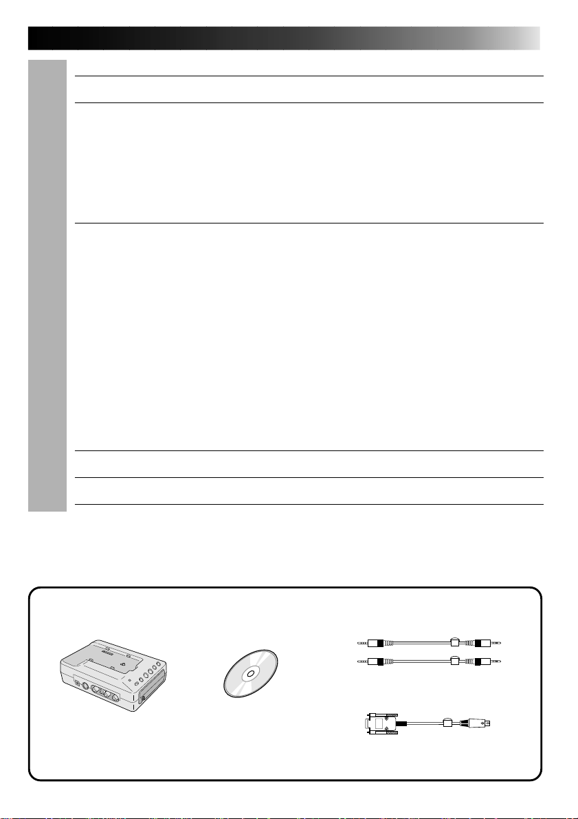
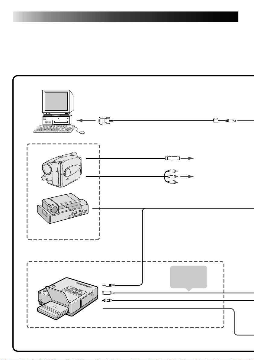
Make sure the GV-DS2E (optional) includes the following accessories:
3.5mm diameter 4-pole cable (x 2)
CD-ROM including two
JLIP Video Capture
Docking Station
GV-DS2
software programs:
JLIP Video Capture and JLIP
Video Producer software
PC Connection Cable
(for PC/AT compatible computers)
Page 8
8 EN
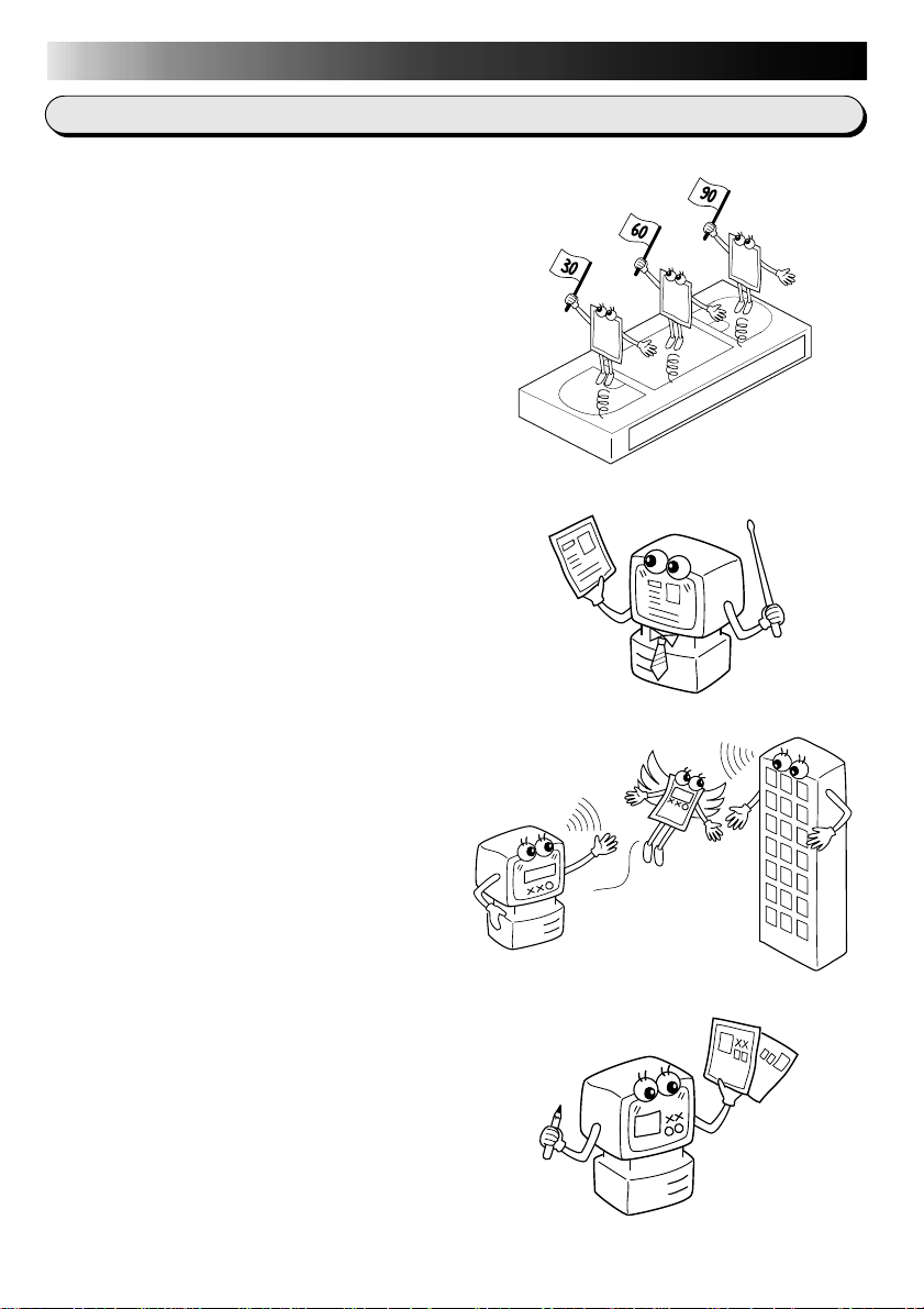
Advanced Applications
Create title indexes for your video
collection
Title index images can be captured from your
favorite recordings in intervals of 30 minutes,
1 hour, 1.5 hours, etc. using the Interval
Capture mode. Print the captured index
images on your PC printer using the computer's Print Screen facility, then attach them to
your cassettes.
Business presentations
Images captured from video can be incorporated into business documents to spice up
your presentations.
MAJOR FEATURES
Internet homepage
Images captured from video can be incorporated in your Internet homepage using image
editing software.
Video journal and postcards
Create your own original postcards, party
invitation cards and the like or keep a video
journal.
Page 9
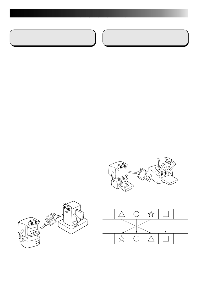
Two software programs are provided.
EN 9
JLIP Video Capture Software
(Z pg. 12 – 41)
JLIP Video Capture Software
This is the software described in this manual.
Video Capture Facility
Video images from video source units such as
camcorders or VCRs can be captured as 768
x 552 still images with 16.77 million colors
through the serial port (RS-232C) of a
WindowsT-operated computer.
JLIP Control Facility
With a JLIP compatible camcorder or VCR,
• all basic video operations can be
executed via the computer display;
• Up to 99 images can be captured
automatically with Program Video
Capture (playing tape — scanning —
transferring to PC)
Data Sharing With JLIP Video
Producer Software
Data can be imported from the JLIP Video
Producer Software.
Data from the Video Capture Software can
also be exported to the Video Producer
Software for Program Playback or Assemble
Editing.
JLIP Video Producer Software
(Z pg. 12, 43 – 69)
JLIP Control Facility
With a JLIP-compatible camcorder, VCR or
video printer (GV-PT2):
• all basic video operations can be
executed on the computer display;
• allows programmed video playback (up
to 99 programs) or assemble editing
• print command can be issued to the GVPT2 video printer
Data Sharing with the Video Capture
Software
Video Capture Software data can be exported
to the Video Producer Software.
Assemble Editing
Selected scenes on a pre-recorded tape can
be edited in a specified sequence.
Pre-recorded tape
(on camcorder)
Recording tape
(on VCR)
Page 10
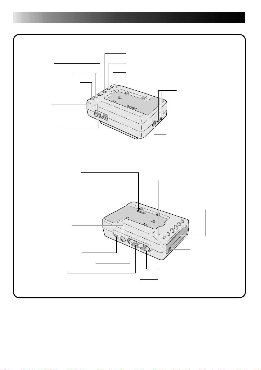
10 EN
STOP button
Rewind (REW) button
Fast-Forward (FF) button
LOCK lever
RELEASE button
Z
Z
p. 13
Z
p. 11
p. 13
Multi connector
• The Docking Station can be connected
with the GR-DVX through this connector.
Never touch it with your hand or hit it
with a hard object; if the pins are
damaged, the connectors will become
unusable due to contact failure.
S-Video output jack
(OUT)
• Outputs S-Video signal.
(Also compatible with S,
S1 and S2 connectors.)
DC IN jack
VIDEO OUT jack
DC OUT jack
•
For dealer use.
Z
p. 13
CONTROLS AND CONNECTORS
PLAY button
PAUSE button
EDIT button
Z
JLIP jack
Level Interface Protocol)
• Connect to a JLIPcompatible comcorder
or VCR to control it
from the computer.
DIGITAL jack Z p. 13, 14
• Connect to the computer’s
RS-232C terminal (COM port).
Charger Indicator (CHARGE)
Remote control sensor
Receives the remote
•
control signals for the
attached Camcorder.
AUDIO OUT jack [R]
AUDIO OUT jack [L]
p. 13 (Joint
EDIT jack
Z
p. 13, 14
Z
Z
Z
p. 11
p. 13
p. 13
Page 11
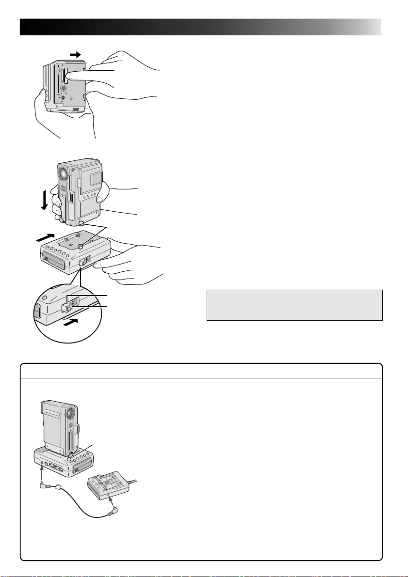
CAMCORDER ATTACHMENT
1
Before attachment, make sure the camcorder's
power is off.
1
2
3
2
4
3
Mark
EN 11
.
OPEN COVER
Slide the Multi connector cover (MULTI) on
the bottom of the camcorder in the direction
of the arrow until you hear a click.
.
ATTACH
Attach the camcorder by aligning the mark on
it with the one on the Video Capture Docking
Station.
.
FIX
Slide the camcorder in the direction of the
arrow.
.
LOCK
While holding the camcorder, slide the LOCK
lever in the direction of the arrow.
To remove the camcorder . . .
… press the RELEASE button. After the LOCK
lever has been released, detach the
camcorder.
Core filter
LOCK lever
RELEASE button
Lock !
Charging a battery Installed in the Camcorder . . .
If you attach the camcorder with a battery installed to the
Video Capture Docking Station, you can charge the battery.
First make sure that the camcorder does not have a DC cord
connected to it before attaching. Turn the camcorder's
Charger
indicator
Power Dial to "OFF" then perform the following steps.
1. Connect the Video Capture Docking Station to the AC
Power Adapter/Charger.
•The Video Capture Docking Station does not use the
camcorder's battery to function. Be sure to connect the
AC Power Adapter/Charger exclusively for use with the
camcorder.
2. Connect the power cord to an AC outlet.
•The Docking Station's charger indicator begins
(CHARGE) blinking to indicate that the charge has
begun. When it stops blinking and lights steadily, the
charge is complete. It takes approx. 2 hours to charge
the battery fully.
NOTE : If it is impossible to slide the lock
lever, repeat steps 2 and 3.
Page 12
12 EN
CONNECTIONS
n To assure safety, make sure all units are turned off before making any connections.
n The video images will be displayed on the LCD screen of the attached GR-DVX series
camcorder. You cannot view the images on the computer screen.
n When connecting the cables (provided with this Video Capture Docking Station or with the
camcorder), be sure to connect the terminals equipped with Core filters to the Video Capture
Docking Station.
n When using the Video Capture Docking Station, use the AA-V90 AC Adapter/Charger
(optional or provided with the camcorder).
To COM port
(RS-232C)
PC
Camcorder equipped
with a JLIP connector
When connected with
the camcorder
GV-PT2 Video Printer
To JLIP
connector
PC connection cable
(provided)
Connect this if
the video unit
has an S-Video
input connector
To DIGITAL
jack (8 pin)
Core Filter
To S-Video
input connector
To video/audio
input jack
3.5 mm diameter
4-pole cable (provided)
To S-Video input connector
To video input connector
When connected with the Video Printer
S-Video cable
Video cable
Page 13
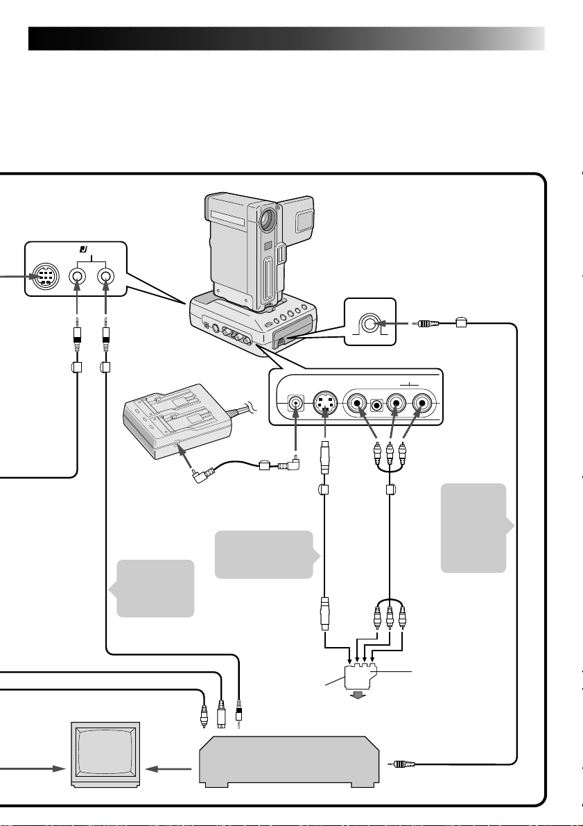
EN 13
n The Video Capture Docking Station does not receive power from the battery pack installed in
the camcorder or from the AC Power Adapter/Charger attached to the camcorder. Be sure to
connect the AA-V90 AC Power Adapter/Charger (exclusively for the Video Capture Docking
Station) to the DC input jack located on the Video Capture Docking Station.
n When connecting the Docking Station to a recording deck with neither a JLIP connector nor
a remote pause jack, first make all connections except for the connection to the edit jack on
pg. 12 and 13, then make the connection to the edit jack on pg. 14.
Digital
camcorder
JLIP
JLIP Video Capture
Docking Station
To JLIP
jack
To JLIP jack
Core Filter
To EDIT jack
Core
Filter
3.5 mm
diameter
4-pole cable
(provided)
Connect
to TV
Core Filter
AC
Power
Adapter/
Charger
Connect this
if the video
unit has a JLIP
connector.
To S-Video output jack
To video output jack
TV
Connect
to TV
DC cord
To DC
output jack
To JLIP jack
Core
Filter
Connect this if the
video unit has an
S-Video input jack.
To S-Video
input jack
VIDEO OUT
select switch
(Y/C or CVBS)
JVC Video unit
(Recording deck)
To
S-Video
output
jack
Core
Filter
S-Video
cable
To
AUDIO
input
jacks
(L/R)
Connect to AV
jack-equipped
TV or to VCR
To VIDEO/
AUDIO OUT
jack
Core
Filter
AUDIO/
VIDEO
cable
To remote pause jack
Make this
connection
when the
recording
deck has
no JLIP
connector.
To
VIDEO
input
jack
Cable adapter
(provided only with
European models)
If your VCR has the
21 pin AV input
connector (SCART),
use the provided
cable adapter.
EDIT
cable
Page 14
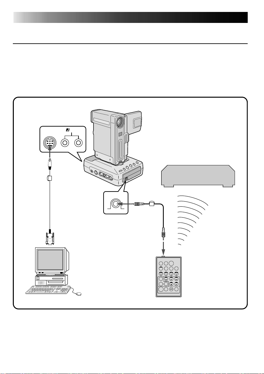
14 EN
CONNECTIONS
(cont.)
WHEN USING A RECORDING DECK WITH NEITHER A JLIP
CONNECTOR NOR A REMOTE PAUSE JACK
When using the JLIP Video Producer Software . . .
● When using a recording deck with neither a JLIP connector nor a remote pause jack, set your
VCR brand using the RM-V711U remote control unit then perform editing using the RMV711U. Also refer to pg. 59 to 62 of the camcorder's instruction manual.
● For all connections except those to the digital connector and edit jack,
JLIP
Digital
camcorder
To
DIGITAL
jack
Z pg. 12 and 13.
Video unit
(Recording deck)
PC connection
cable (provided)
To COM port
(RS-232C)
PC
* Use the editing cable provided with the camcorder.
To EDIT jack
Editing cable*
To remote
pause jack
Core
filter
TW
RM-V711U
Remote
control unit
Page 15

JLIP VIDEO CAPTURE
SOFTWARE SECTION
Operating Environment .......................................... 16
Connectable Devices ............................................. 16
Installation ........................................................ 17
Open & Close ..................................................... 18
Initialization ...................................................... 20
How The Desktop Works........................................ 22
Video Capture .................................................... 26
Save Picture ...................................................... 31
Picture Format Setting........................................... 32
Additional Operations ........................................... 33
Troubleshooting................................................... 38
List of Error messages........................................... 40
EN 15
Page 16
16 EN
GETTING STARTED
What is video capture software ?
Video capture software is a type of application program that allows you to capture video
images from camcorders and VCRs and store them in personal computers running under the
WindowsT operating system. These images can be transferred from the video source to the
computer via a standard RS-232C communication interface. By processing the captured
images with commercially available image editing software, you can create your own unique
and highly personal illustrations and graphics for incorporation into everything from postcards
to newsletters and Internet homepages. What’s more, you can also use your computer to edit
your original video recording and produce a fun-to-watch, professional-looking video program.
What is JLIP ?
JLIP* stands for Joint Level Interface Protocol, a new communication protocol which allows AV
units equipped with a JLIP terminal to be controlled by a personal computer.
*
is a registered trademark of JVC.
Operating Environment
● Personal computer with MicrosoftT WindowsT 3.1 or WindowsT 95
● CPU Intel DX4T or higher processor
● Minimum RAM requirement: more than 8 MB
● Available Hard Disk space of at least 8 MB
● Colour display capable of at least 640 x 480 pixels, 256 colours
Recommended 1024 x 768, 16.77 Mil colours
● 1 free serial transmission port, compatible with 9600 bps transmission rate, connectable to
RS-232C with 9 pin serial connector.
Recommended compatible with UART 16550A
● Mouse (WindowsT compatible)
● CD-ROM drive
Note : An optional 9 pin serial conversion adapter is required for computers using serial
communication port other than standard 9 pin.
* MicrosoftT and WindowsT are either registered trademarks or trademarks of Microsoft Corporation in the
United States and/or other countries.
* Other product and company names included in this instruction manual are trademarks and/or registered
trademarks of their respective holders.
Connectable Devices
● When using JLIP with Video units equipped with a JLIP connector : GR-DVX series
● The JLIP Video Capture Software can be used with the GV-CB1 and GV-DS1.
Page 17

INSTALLATION (JLIP Video Capture Software)
WINDOWST 95
Refer to the WindowsT 95 manual or your
computer’s manual for details on basic
WindowsT 95 operating procedures.
WINDOWST 3.1
Refer to the WindowsT 3.1 manual of or your
computer manual for details on basic
WindowsT 3.1 operating procedures.
EN 17
Installation Procedure
This software offers you the choise of viewing
on-screen messages in English or French.
Select the desired language during installation by performing the following steps.
*To start the setup program . . .
Launch WindowsT 95
1
•Close any other applications that are
running.
Insert the "JLIP Video Capture" CD-ROM
2
into the CD-ROM drive.
Choose "Run" from "Start" on the taskbar.
3
If you want English on-screen
4
messages . . .
If the "JLIP Video Capture" CD-ROM is in
Drive D, type "D:\JCPTE\SETUP" in the
box to the right of "Name". If the disk is
in Drive E, type "E:\JCPTE\SETUP".
If you want French on-screen
messages . . .
If the "JLIP Video Capture" CD-ROM is in
Drive D, type "D:\JCPTF\SETUP" in the
box to the right of "Name". If the disk is
in Drive E, type "E:\JCPTF\SETUP".
•Click "OK".
•Once the setup program is running,
simply follow the instructions displayed
on-screen.
•When setup is complete, the "JLIP
Video Capture" icon appears on the
screen.
•"JLIP VIDEO CAPTURE Setup was
completed successfully." appears.
Click "OK" to complete installation.
5
Installation Procedure
This software offers you the choise of viewing
on-screen messages in English or French.
Select the desired language during installation by performing the following steps.
*To start the setup program . . .
Launch WindowsT 3.1
1
•Close any other applications that are
running.
Insert the "JLIP Video Capture" CD-ROM
2
into the CD-ROM drive.
Choose "Run" from "File" in the "Program
3
Manager".
If you want English on-screen
4
messages . . .
If the "JLIP Video Capture" CD-ROM is in
Drive D, type "D:\JCPTE\SETUP" in the
box to the right of "Name". If the disk is
in Drive E, type "E:\JCPTE\SETUP".
If you want French on-screen
messages . . .
If the "JLIP Video Capture" CD-ROM is in
Drive D, type "D:\JCPTF\SETUP" in the
box to the right of "Name". If the disk is
in Drive E, type "E:\JCPTF\SETUP".
•Click "OK".
•Once the setup program is running,
simply follow the instructions displayed
on-screen.
•When setup is complete, the "JLIP
Video Capture" icon appears on the
screen.
•"JLIP VIDEO CAPTURE Setup was
completed successfully." appears.
Click "OK" to complete installation.
5
NOTE : This instruction manual uses
English on-screen messages in its
explanation.
Page 18

18 EN
The Video Capture software can be started up in the same way as any other program running
under Windows. The procedure differs slightly depending on whether you’re using WindowsT
3.1 or WindowsT 95.
OPEN & CLOSE (Basic Operation Procedure)
Preparation
• Turn on your computer.
• Turn on the video source units (such as camcorders and VCRs).
• If you want to capture a still picture from a recorded tape, load the tape into the video unit.
• If you want to capture an image from the data stored in the JLIP Video Producer Software, be
sure to load the disk on which the image is stored.
Close any programs that are running. You cannot run other programs simultaneously with
the Video Capture software.
With WindowsT 3.1, open the group of application icons in the Program Manager and
double-click the application icon you want to launch.
With WindowsT 95, click the [START] button on the taskbar, and the Program menu
appears on the screen. Move the mouse pointer over the program entry you want to run
and click to start the program.
Now let’s start the program.
If you’re using WindowsT 3.1, open the JLIP Video Capture group in the "Program Manager" and
double-click the JLIP Video Capture icon.
If you’re using WindowsT 95, select JLIP Video Capture from the "Start menu" and click to start.
INITIALIZING JLIP page 20
SELECT UNITS page 21
MAIN DESKTOP WINDOW page 22
Page 19

EN 19
HOW TO CLOSE THE PROGRAM
Double-click the control menu button in WindowsT 3.1 or click "Exit" in the "File (F)" menu.
In WindowsT 95, simply click the Close button.
If you try to close the program with no image
data saved, the message "The album has not
been saved. Save?" appears. Please note that
if you close without saving, all unsaved
captured data will be deleted.
1
.
Click "Exit" from "File" in the menu bar.
•The program closes.
File
New Album
Open Album
Save Album
Open JLIP (jlp) File
Save As JLIP (jlp) File
Save Image As…
Exit
Ctrl+N
Ctrl+O
Ctrl+S
Ctrl+A
Page 20
20 EN
INITIALIZATION
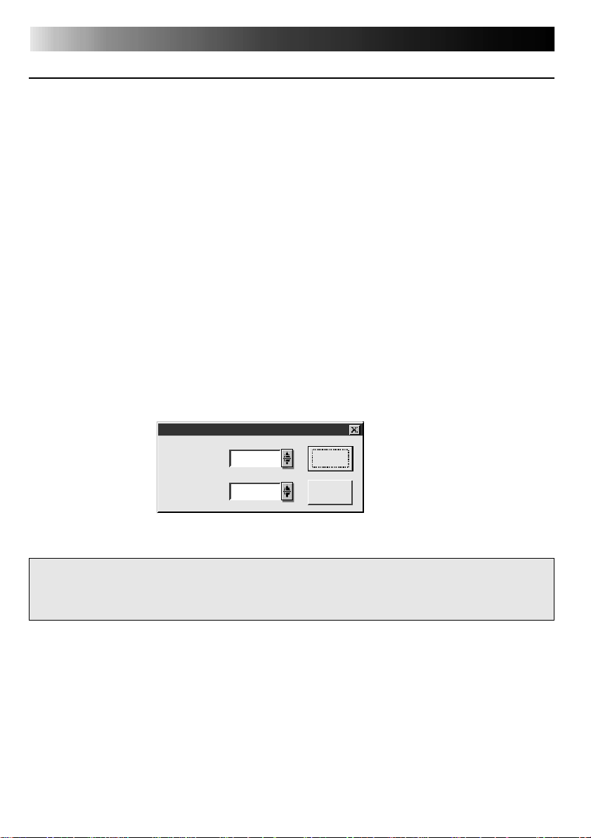
INITIALIZING JLIP
The first time you start the Video Capture software, JLIP initialization is required. This sets which
of the computer’s COM ports (connector into which the RS-232C cable is plugged) is connected
to the JLIP Video Capture Docking Station. The initialization window automatically appears the
first time you start the software after installation. Do not forget to carry out this JLIP initialization
procedure. The JLIP must be initialized again whenever you connect a new image source or
other unit to the JLIP Video Capture Docking Station.
1
.
Start the JLIP Video Capture software.
2
.
The "JLIP Initialization" screen automatically appears.
3
.
Select "COM Port".
•COM1 through COM4 ports are available. Check to see which COM port is connected to
the JLIP Video Capture Docking Station and select it.
4
.
Select "Transfer Rate".
•Normally select 38400.
•38400 may not be available on some computers. When transmission errors take place
during use, switch to 19200 or 9600. Image data transmission will be slower at these
speeds.
5.
Click "OK" . Call up the "JLIP Initialization" window and check the connected units.
JLIP Initialization
COM Port COM 1
38400Transfer Rate
NOTE : If you want to change a unit or COM port or Transfer Rate, select "Initialize" from
"Set-up" in the menu bar to call up the "JLIP Initialization" window. Repeat this
setting procedure.
If a connection is incorrect, a connected unit is not turned on, or the connection ID numbers
overlap, the message "Connection error" appears. Click "OK" to return to the Main desktop.
OK
Cancel
Page 21
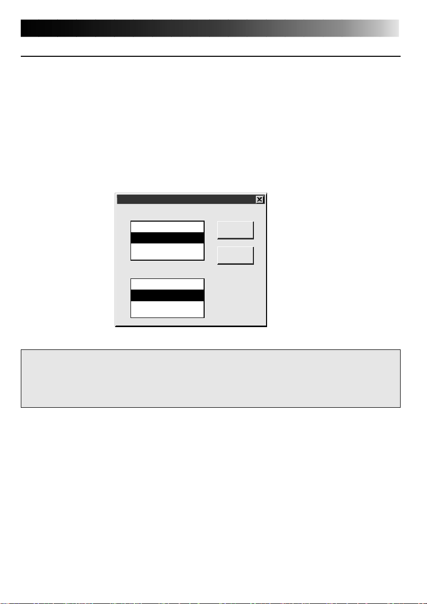
SELECT UNITS
6
.
Call up the "Device Selection" window.
7
.
Click the name of the unit required.
•The word "VCRCAMERA" appears in the VCR box to indicate the Video source unit is now
in use.
•The word "MODULE" appears in the Video Capture box to indicate the Video Capture
Docking Station is now in use.
•Only one VCR and one Video Capture device can be selected.
8
.
Click "OK".
•The main desktop window returns (setting complete).
Device Selection
VCR
Not connected
06:VCRCAMERA
Video Capture
Not connected
83:MODULE
OK
Cancel
EN 21
NOTE : The "Device Selection" window automatically appears when JLIP initialization is
complete. However, if you want to select equipment whose JLIP initialization has
already been carried out, select "Device Change" from "Set-up" in the menu bar to
call up the "Device Selection" window.
Page 22
22 EN
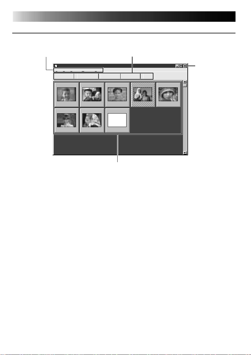
MAIN DESKTOP WINDOW
1
Menu bar
HOW THE DESKTOP WORKS
2
Control buttons
JLIP Video Capture [–Untitled Folder–] (Untitled)
File Edit Set-up Window Help
TRANSFERCAPTURE
01
00:01:23:120200:02:17:210300:07:01:19
06
00:39:03:110700:47:53:03
1
Menu bar
Displays function menus. See the next page for detailed information.
2
Control buttons
•CAPTURE button (Z page 27)
Press to CAPTURE a desired image from an image source. When pressed, an index
image appears under this button.
•TRANSFER button (
The TRANSFER button is used to start Automatic Transfer. Automatic Transfer is divided
into Program Capture and Interval Capture.
•MEMORY/INPUT buttons
These buttons do not function.
•JLIP button (
The JLIP Video Capture software and JLIP Video Producer software cannot run simultaneously. When you want to run the JLIP Video Producer software, press this button to call
up a cross bar and run the software. To resume using the JLIP Video Capture software,
first select "Close Serial" from "Set-up" on the JLIP Video Producer Software's menu bar,
then press the JLIP button.
Z pages 29 through 30)
Z pages 43 through 69)
MEMORY
--:--:--:--
INPUT
04
00:37:05:06
08
3
Image display area
JLIP
05
00:20:39:18
Close button
Page 23

3
Image display area
Each time you press the Capture button an index image is captured into the image area.
Up to 99 images can be captured, with up to five images in one horizontal frame. Index
images are provided to allow you to confirm that you have captured the images you want.
Index image data: 80 x 60 pixels Full image data: 768 x 552 pixels
Index image
Click to select an index image, and
•the border of the Image display
box turns green
•Double-click an index image, and
Full image data will appear if it
has already been transferred
Index numbers are
automatically assigned
02
Image display box
00:02:17:210300:07:01:190400:37:05:06
EN 23
Counter display
Indicates the current tape position
eg. 00 : 02 : 17 : 21
Hour:Min:Sec:Frame
Colours of counter numerals
Black : Full image data transferred
White: Full image data not
transferred (only index
image data transferred)
When an image display box is double-clicked
Full image data will appear if it has already been transferred.
Displays the full image (Index No.02)
File
Save Image AS...
Close
Ctrl+A
Ctrl+X
Hatched like this
when counter
time is corrected
(Z p. 33)
Page 24

24 EN
HOW THE DESKTOP WORKS
(cont.)
MENU BAR
All program functions can be selected from the menus in the menu bar. Click any item in the
menu bar to open the corresponding pulldown menu. Then click the desired command in the
pulldown menu. Some menu entries are invalid depending on the program status. Invalid
commands appear lighter than valid commands.
JLIP Video Capture
File Edit Set-up Window Help
New Album
Open Album
Save Album
Open JLIP (jlp) File
Save As JLIP (jlp) File
Save Image As…
Exit
Ctrl+N
Ctrl+O
Ctrl+S
Ctrl+A
INPUTMEMORY
Each pulldown menu is configured as follows
File
New Album
Open Album
Save Album
Open JLIP (jlp) File
Save As JLIP (jlp) File
Save Image As…
Exit
Edit
Transfer the Index Image
Transfer the Full Image
Modify…
Delete
Ctrl+N
Ctrl+O
Ctrl+S
Ctrl+A
Del
Erases the image currently on screen and creates a new image
Opens an index file (Z p. 35).
Stores the index image on screen (Z p. 31).
Opens a JLIP Video Producer software file or JLIP Movie Player
software file (Z p. 36) .
Converts to and saves as a JLIP Video Producer software file or
JLIP Movie Player software file (Z p. 37).
Saves the image data file to another folder or drive (Z p. 31).
Closes the program (Z p. 19).
• An index image of the image data in the Video Capture Docking
Station memory is transferred to your computer and displayed in
the selected image box (in the Step by Step capture mode).
• The video source unit scans the selected counter value and
transfers the index image to your computer (in the automatic
capture mode) (
• A full image of the image data in the Video Capture Docking
Station memory is transferred to your computer (in the Step by
Step capture mode).
• The video source unit scans the selected counter value and
transfers the full image data (768 x 552 pixels) to your computer
(in the automatic capture mode) (
Changes the scan timing in the automatic capture mode by
changing the counter preset (
Deletes the index image (Z p. 34).
Z
p. 33).
Z
Z
p. 33).
p. 33).
Page 25

Two different modes available: Step by Step Capture and Automatic Capture
Set-up
Capture Mode
Image Format
Device Change
Preroll
Initialize
ID Change
Counter Reset
Window
Arrange Index
VCR
(
Selects image data format to be used in the transfer and capture mode
(
To initialize a connected unit or to change a connected unit (
Adjusts the Preroll time of the playback VCR. When Auto Capture is
performed with no Preroll time selected, "Preroll" is automatically set to
"Standard". If there are disturbances in the captured image when Auto
Capture is tried using a VCR with High-Speed (Turbo) Search, select "Long"
instead (
Initialize when changing a COM port or transfer rate (Z p. 20).
Changes the Video Capture unit’s ID number (
Resets the VCR's counter (
[VCR] operation window
EN 25
Z
p. 27, 28, 30).
Z
p. 32).
Z
p. 21).
Z
p. 52).
Z
p. 34).
Z
p. 33).
Deletes space when an index image has been deleted (Z p. 34).
The VCR operation window appears to allow the computer to operate the
VCR.
VCR POWER button
FF/FF Search button
REW/REW Search button
Help
Contents
About JLIP Video Capture
NOTE : Counter reset
If you use a DV-format digital camcorder, counter information is represented by the
time code written on the tape. Counter reset is not possible.
VCR
I
STOP button
F1
Counter display
00:01:23:12F
Reverse Slow button
Capture
Transfer
PLAY button
Display Help menu
Display version information of this software.
Forward Slow button
PAUSE button
Capture button
Transfer button
Page 26

26 EN
VIDEO CAPTURE
CAPTURING VIDEO IMAGES
There are three capture modes available: Step by Step, Program and Interval.
Image data flow
Digital
camcorder
When storing full image data on a 2HD disk,
• An image saved in the bitmap data format can be stored on one disk.
• About 28 images saved in the JPEG video compression format can be stored on one disk.
This is the case when using floppy disks formatted for 1.44 MB.
Video signal
(Image stored in video memory)
Full image data
(with a resolution of
768 x 552 pixels)
2 types of video data
•Bitmap data
Approx. 1.3MB
•JPEG video
compression data
Approx. 50 kB
GV-DS2
Index image data
(with a resolution
of 80 x 60 pixels)
PC
(video data are stored on
a hard disk or the like)
NOTE:
•The index image is displayed in the
image display box.
•Each time the image display box is
double-clicked, the full image data (768
x 552 pixels) is displayed only after full
image data transfer is finished.
Page 27

STEP BY STEP CAPTURE
Use the Step by Step Capture mode when you want to:
•Capture a smaller number of images
•Confirm the images being captured.
Preparation
•Make sure all units are properly connected
(Z p. 12).
Set-up
Capture Mode
Image Format
Device Change
Preroll
Initialize
ID Change
Counter Reset
JLIP Video Capture
File Edit Set-up Window
TRANSFERCAPTURE
Step by Step
Automatic
•Click "Image Format" in "Set-up" and select
the desired format (
1
2
EN 27
Z p. 32).
Open the menu bar and click "Set-up" —
"Capture Mode" — "Step by Step".
•The Step by Step Mode is entered.
Click "CAPTURE" on the image you want
to capture.
•Click "Window" — "VCR" to have the
VCR scan the picture in the VCR
Operate window (
•When you press the CAPTURE button,
full image data (768 x 552 pixels) is
captured into the Video Capture
Docking Station memory. Index image
data (80 x 60 pixels) is simultaneously
transferred to the computer.
Z p. 25).
NOTES:
•Index image/Full image data are
transferred to the image display boxes
bordered in green. Click and select the
desired box(es).
•When transferring full image data using
the Bitmap image format (
transfer takes a very long time, causing
the video source unit to stop playback
automatically.
.bmp), the
9
Index image data is transferred to the
3
computer.
•The message "No.1 index image being
transferred" appears during data
transfer.
The message "Transfer the full image ?
4
Yes/No" appears. Click "Yes". Full image
data (768 x 552 pixels) is transferred to
the computer.
•You cannot use the TRANSFER button
in Step by Step Transfer mode.
The full image data is transferred to the
5
computer.
•The message "No.1 image being
transferred" appears during data
transfer.
Repeat steps 2 through 5 as required.
6
Page 28

28 EN
VIDEO CAPTURE
(cont.)
AUTOMATIC CAPTURE
There are two types of automatic capture: Program mode and Interval mode. You can save time
in either mode because, once the initial settings have been stored or you have decided what
pictures to capture, the subsequent capture process is carried out automatically.
PROGRAM CAPTURE
In the Program Capture mode, select the images you want to capture, and the JLIP Video
Capture Docking Station will automatically capture and transfer the images to your computer.
Preparation
•Make sure all units are properly connected
(Z p. 12).
•Insert a tape into the video source unit.
Click "Image Format" in "Set-up" and select
"Field Picture" in the Capture Mode
Z p. 32).
(
Set-up
Capture Mode
Image Format
Device Change
Preroll
Initialize
ID Change
Counter Reset
Step by Step
Automatic
Open the menu bar and click "Set-up" —
1
"Capture Mode" — "Automatic".
•The "Automatic Transfer" window
appears.
Select data to be transferred.
2
•When you select "Index Image", index
image data (80 x 60 pixels) is transferred to your computer.
•When you select "Index & Full Image",
both the index image data (80 x 60
pixels) and full image data (768 x 552
pixels) are transferred to the computer.
Select "Program Capture" and click
3
"OK".
NOTE:
•Before transferring your images, make
sure that enough space is available on
your hard disk. For full image data
space requirements,
•When transferring full image data using
the Bitmap image format (9.bmp), the
transfer takes a very long time, causing
the video source unit to stop playback
automatically.
Z p. 26.
Page 29

Click "Window" — "VCR" to call up the
4
VCR Operation window.
EN 29
VCR
Operate the video source unit via the
5
I
00:01:23:12F
Capture
Transfer
VCR Operation window.
Click the "Capture" button on the desired
6
video image, and index image data (80 x
60 pixels) is transferred to the computer.
•The message "No.1 index image being
transferred" appears during data
transmission.
Repeat steps 4 through 6 as necessary.
7
Click "Transfer" button.
8
•If you want to capture full image data
(768 x 552 pixels) after capturing the
"Index Image" in step 2, select "Index &
Full Image" and click "OK", then click
the "Transfer" button.
1. The message "Index No.1 being scanned"
appears while the video source unit is
scanning the picture to be captured.
2. The message "No.1 index image being
transferred" appears. When you select
"Index & Full Image" in step 2, the
message "No.1 image being transferred."
appears while the full image data is being
transferred to the computer.
3. The images captured in step 7 are scanned
by the video source unit and automatically
transferred to the computer.
Page 30

30 EN
INTERVAL CAPTURE
The Interval Capture mode is best suited for
capturing images at set intervals from a
camcorder.
VIDEO CAPTURE
(cont.)
Preparation
•Make sure all units are properly connected
Z p. 12).
(
Insert a tape into the video source unit.
•
Click "Image Format" in "Set-up" and select
"Field Picture" in the Capture Mode (
Z
p. 32).
Set-up
Capture Mode
Image Format
Device Change
Preroll
Initialize
ID Change
Counter Reset
VCR
I
NOTE:
•Make sure that enough hard disk space is
available on your computer before
executing video transfer.
For full image data space requirements,
Step by Step
Automatic
00:01:23:12F
Capture
Transfer
Z p. 26.
•Transfer of index image data/full image data
starts at the image box bordered in green.
Click and select the desired image box.
•When transferring full image data using the
Bitmap image format (
takes a very long time, causing the video
source unit to stop playback automatically.
.bmp), the transfer
9
Open the menu bar and click "Set-up" —
1
"Capture Mode" — "Automatic".
•
The "Automatic Transfer" window appears.
Select the data to be transferred.
2
•When you select "Index Image", index
image data (80 x 60 pixels) is transferred
to your computer.
•When you select "Index & Full Image",
both index image data (80 x 60 pixels)
and full image data (768 x 552 pixels) are
transferred to the computer.
Select "Interval Capture".
3
Set the interval.
4
•Select the time interval at which pictures
are captured.
Set the number of pictures to be captured
5
and click "OK".
•From 1 up to 99
Click "Window" — "VCR" to call up the
6
VCR Operation Window. Start video
playback a few seconds prior to the point
where you want image capturing to start.
Operate the video source unit via the VCR
7
Operation window and click the "Transfer"
button at the desired picture.
1. The message "No. 1 index image being
transferred" appears while the index image
data is being transferred to the computer.
2. When you select "Index & Full Image" in
step 2, the message "No. 1 image being
transferred" appears while the full image
data is being transferred to the computer.
3. The message "Index No. 2 being scanned"
appears while the video data are fastforwarded and played at the time intervals
set in step 4 to scan the video data on the
VCR.
• The image selected when "Transfer" is
clicked is captured and subsequent images
are captured at the time interval specified
by the counter value selected in step 4.
• The video source unit enters the Pause
mode when capture is complete.
Page 31

SAVE PICTURE
SAVING
Select when storing the contents displayed in the image display area (page 23).
EN 31
File
New Album
Open Album
Save Album
Open JLIP (jlp) File
Save As JLIP (jlp) File
Save Image As…
Exit
Enter folder name
Save Album
Folder:
c:\capture\index001
(Untitled)
Title:
c:\
capture
c:
Select directory Select drive
Ctrl+N
Ctrl+O
Ctrl+S
Ctrl+A
Enter title name
OK
Cancel
Open the menu bar and click "File" —
1
"Save Album" .
•The "Save Album" window appears.
Type the folder name and title.
2
•You can save without entering any title.
Click "OK".
3
•The file is saved.
SAVE THE FULL IMAGE DATA
You can save a file under another name or in another folder so that you can edit it without
losing the original.
By processing the captured images with commercially available image editing software, you
can create your own unique and highly personal illustrations and graphics for incorporation
into everything from postcards to newsletters and Internet homepages.
File
New Album
Open Album
Save Album
Open JLIP (jlp) File
Save As JLIP (jlp) File
Save Image As…
Exit
NOTE:
•It is not possible to change the image format
when saving the full image data (Z p. 32).
•If the full image data has not been transferred
to the computer, it is not possible to save it.
First transfer the full image data, then save it.
Ctrl+N
Ctrl+O
Ctrl+S
Ctrl+A
Click the image display box of the Index
1
No. to be saved.
•The image display box is framed in
green.
Click "File" — "Save Image As…" on the
2
menu bar.
•The "Save Image As… (Index No.
window appears.
Click the name of the desired folder
3
(directory) in the Select Directory box
and enter the file name.
•When saving the data to floppy disk,
enter the drive name as well.
Click "OK".
4
)"
Page 32

32 EN
PICTURE FORMAT SETTING
SELECTING A PICTURE FORMAT
Under "Image Format", you can specify the full image data format and the capture mode.
Open the menu bar
1
and click "Set-up"
— "Image Format".
•The "Image
Format" window
appears.
Select format.
2
•There are two different settings available: "JPEG (
(9. bmp)". Refer to "Picture Data
Format" below for details.
TRANSFER DATA
Full image data can be captured and transferred in two different formats.
9. jpg)" and "Bitmap
Set-up
Capture Mode
Image Format
Device Change
Preroll
Initialize
ID Change
Counter Reset
Select capture mode.
3
•There are two different settings avail-
able: "Frame Picture" and "Field
Picture". Refer to "Capture Mode"
below for details.
Click "OK".
4
•This completes picture format setting.
•This setting takes effect the next time
you use the capture function.
Picture Data Format
● JPEG (9. jpg)
This is the default setting. If you do not set Picture Format, image data is captured in this
•
format.
•
JPEG (Joint Photographic Expert Group) is a leading standard defining the compression and
decompression of still colour pictures.
•
The quantity of transferred data appears smaller because the images are compressed. This
results in a shorter transfer time.
● Bitmap (9. bmp)
•
Transfer time is longer when you use this format because there is no data compression. The
benefit is that picture quality is maintained with no deterioration.
•
Bitmap is a data format representing characters and graphics with combinations of pixels.
Full image data resolution is 768 x 552 pixels with 16.77 million colours (24-bit colour).
Index image data resolution is 80 x 60 pixels with 16.77 million colours (24-bit colour).
Capture Mode
● Frame Picture
•
This is the default setting. If you do not set Picture Format, images are captured in this
mode.
•
Since a frame consists of two overlapping 1/50 sec. images (one 1/25 sec. image forms a
field), it is unstable when capturing fast-moving motion pictures.
● Field Picture
While a field contains only half the data of a frame — meaning that vertical resolution is
•
half that of a frame — images captured from a fast-moving motion picture are more stable
than when captured with "Frame Picture".
Page 33

ADDITIONAL OPERATIONS
EN 33
COUNTER VALUE CHANGE
If you want to replace a captured image with a different one, you can capture the new one by
changing the counter value.
02
00:02:17:21
Edit
Transfer the Index Image
Transfer the Full Image
Modify…
Delete
02
00:01:23:12
02
00:01:23:12
NOTE : Note that if the index image data
is saved in step 4, the hatching
pattern indicating the change will
no longer appear the next time it
is called up.
Del
Click the image display box of the index
1
number you want to change.
•The box is bordered in green.
Open the menu bar and click "Edit" —
2
"Modify…".
•The "Modify Capture Point" window
appears.
Enter a new counter value.
3
Click "OK".
4
•The index image is surrounded by a
hatching pattern indicating that a
change is being made.
•The counter value is changed to the
value you just entered.
Open the menu bar and click "Set-up" —
5
"Capture Mode" — "Automatic", then
select "Program Capture" in the "Automatic Transfer" window and click "OK".
Play the tape on the video source unit
6
and click "Edit" — "Transfer the Index
Image".
•Index image data at the counter setting
is captured.
•Be sure to complete steps 1 through 7.
If they are not all followed, the index
image and the full image will be
different as the full image data will not
have been changed in step 6.
Click "Edit" — "Transfer the Full Image".
7
•Full image data at the counter setting is
transferred.
COUNTER RESET
You can change the counter setting on connected video source units (VHS, VHS-C). Since digital
camcorders record the counter as a time code, the counter on a digital camcorder cannot be reset.
Set-up
Capture Mode
Image Format
Device Change
Preroll
Initialize
ID Change
Counter Reset
Open the menu bar and click "Set-up" —
1
"Counter Reset".
•The VCR's counter is reset.
Page 34

34 EN
ADDITIONAL OPERATIONS
DELETE INDEX IMAGE AND FULL IMAGE
You can delete any captured picture. Both index image (80 x 60 pixels) and full image (768 x
552 pixels) are deleted.
(cont.)
02
00:02:17:21
Edit
Transfer the Index Image
Transfer the Full Image
Modify…
Delete
Window
Arrange Index
VCR
Del
1
2
3
CHANGE ID
You can change the Video Capture Unit’s ID number.
Click the image display box you want to
delete.
•The box is bordered in green.
Open the menu bar and click "Edit" —
"Delete".
•This deletes the selected image data.
Then click "Window" — "Arrange
Index".
•This removes the deleted index image’s
space and renumbers the remaining
index display box. You can still run the
program without re-arranging the
index.
Set-up
Capture Mode
Image Format
Device Change
Preroll
Initialize
ID Change
Counter Reset
Open the menu bar and click "Set-up" —
1
"ID Change".
•ID Change window appears.
Enter a new ID number.
2
Click "OK".
3
•This completes the ID number change.
Open the menu bar and click "Set-up" —
4
"Initialize".
•The "JLIP Initialization" window
appears.
•Start JLIP initialization (
Z p. 20, 21).
Page 35

EN 35
CREATE NEW FOLDER
Creating a new folder (directory) is a good idea when capturing an image from another video
tape.
File
New Album
Open Album
Save Album
Open JLIP (jlp) File
Save As JLIP (jlp) File
Save Image As…
Exit
OPEN INDEX
File
New Album
Open Album
Save Album
Open JLIP (jlp) File
Save As JLIP (jlp) File
Save Image As…
Exit
Ctrl+N
Ctrl+O
Ctrl+S
Ctrl+A
Ctrl+N
Ctrl+O
Ctrl+S
Ctrl+A
Open the menu bar and click "File" —
1
"New Album".
•The image display area is refreshed.
•If the index image data on screen is not
saved, you will be asked whether to
save or not.
Open the menu bar and click "File" —
1
"Open Album".
•The "Open Album" window appears.
Select the name of the folder (directory).
2
Click "OK".
3
Page 36

36 EN
JLIP VIDEO PRODUCER SOFTWARE
USING JLIP VIDEO PRODUCER SOFTWARE DATA
The Video Capture Docking Station can capture JLIP Video Producer software data at an edit-in
point corresponding to a preset counter number.
Preparation
•Make sure all units are properly connected
Z p. 12).
(
•Insert the tape program edited with the
Video Producer Software into the video
source unit.
•If the data is stored on a floppy disk, load
File
New Album
Open Album
Save Album
Open JLIP (jlp) File
Save As JLIP (jlp) File
Save Image As…
Exit
Ctrl+N
Ctrl+O
Ctrl+S
Ctrl+A
disk into the floppy disk drive.
Open the menu bar and click "File" —
1
"Open JLIP (jlp) File".
•The "Open JLIP (jlp) File" window is
displayed.
Double-click the name of the desired
2
folder (directory) in the Select Directory
box.
•If the data is stored on a floppy disk,
enter the drive name.
Click on the file name to select it.
3
Click "OK".
4
•The computer monitor displays Scene
No., counter number at Edit-in Point,
and a blank image box.
Open the menu bar and click "Set-up" —
5
"Capture Mode" — "Automatic".
Select the data you want to transfer and
6
"Program Capture" and click "OK".
Click the "TRANSFER" button.
7
•The image data scanned by the video
source unit is automatically transferred
to your computer.
Page 37

EN 37
HOW TO STORE JLIP VIDEO PRODUCER SOFTWARE DATA
Data from this unit can be converted to JLIP Video Producer software files.
If index image data is saved as a JLIP Video Producer software file, the file can be printed with
the optional GV-PT2E Video Printer.
Refer to the instruction manual for details.
Preparation
•Make sure all units are properly connected
(Z p. 12).
•Insert a video tape into the video source
unit.
•If you want to store the data on a floppy
disk, load a data disk into the floppy disk
drive, create a directory and sub-directory
Z p. 54).
File
New Album
Open Album
Save Album
Open JLIP (jlp) File
Save As JLIP (jlp) File
Save Image As…
Exit
Ctrl+N
Ctrl+O
Ctrl+S
Ctrl+A
on the data disk (
Open the menu bar and click "File" —
1
"Save As JLIP (jlp) File".
•The "Save As JLIP (jlp) File" window is
displayed.
Enter the folder name (directory) and file
2
name.
•If you want to store the data on a
floppy disk, enter the drive name.
Click "OK".
3
•The data converted to a JLIP Video
Producer software file is stored on the
floppy disk in the selected drive.
•JLIP Video Producer software files can
be used for video program editing or
printed with the video printer
(Z p. 60, 62).
NOTE:
When stored data is opened with the JLIP
Video Producer software, the edit-in and
edit-out points have the same counter
value. When you want to perform
program editing, change the counter
number at the edit-out point in the JLIP
Video Producer software’s "Modify Edit
Points".
Page 38

38 EN
NOTE : External noise or disturbance may interfere with the microprocessors built into the
JLIP Video Capture Docking Station. If this happens, turn the power off and then turn
it on again.
TROUBLESHOOTING
Problem
JLIP Video Capture Software
does not work.
Operating the camcorder
(capturing video images
through the computer etc.)
is not possible.
No effect when clicking the
Input Select/Memory
buttons.
The video unit does not
operate when "Window" —
"VCR" in the menu bar and
"VCR" in the "VCR" operation window are clicked.
The"VCR" operation
window display shows a
different operation from
what the video unit is
actually doing.
Cause
v Does the JLIP Video Producer Software or
the JLIP Movie Player Software run ? The
JLIP Video Capture Software cannot run
together with it.
v
If the camcorder is attached to the JLIP
Video Capture Docking Station with the
battery pack installed or with the AC Power
Adapter/Charger attached, it is impossible to
operate the camcorder using the computer.
v These buttons do not function.
v The counter display in the "VCR" operation
window turns blue.
Is your video unit compatible with JLIP ?
v
Only JLIP-compatible units can be operated.
If you are using a JLIP-compatible unit and
it still won’t work, check to make sure that
it is correctly connected.
v Is the video unit selected in "Select Unit" ?
Select correctly.
v Initialize JLIP.
v Make sure the video unit is turned on.
v Slow Play in the VCR operation window
automatically switches to Play after
approximately 10 to 20 seconds.
v In some cases, the video unit may continue
slow-motion playback even when the
"VCR" operation window changes from
Slow Play to Play. Check your video unit’s
instruction manual for details.
Page
—
—
—
25
12 – 14
21
20
25
On-screen display of video
unit is not stored in
memory.
Counter display appears in
the image display box even
when there is no tape in the
video unit.
v It is not possible to capture the on-screen
display (date, time cord etc.) into the
computer.
v When capture video data from a powered-
on camcorder with no tape loaded, a
counter display may appear in the image
display box. Images corresponding to the
displayed counter number can no longer be
caputred.
—
—
Page 39

EN 39
Problem
Cannot capture video data
with the desired counter
number.
Counter cannot be reset.
Program capture suddenly
stops.
After finishing video
capture, the video file
remains in the JCPT folder
(where the program run file
is contained).
JLIP initialization not
possible.
With Video capture/
Transfer done in Automatic
Transfer mode, the captured
image looks like two
pictures laid one upon
another.
Cause
v There may be a slight difference between
the counter of the video image that you
want to capture and the Index image data/
Full image data captured in the computer.
This is not a malfunction.
v Counter reset is not available with digital
camcorders.
v When you start program capture at the
beginning of the tape, the video unit stops
playback, ending program capture.
Start video capture about 20 seconds after
the point where the recording begins.
v If you want to erase the file because of
limited hard disk space, start the program
once then close it. The video remaining in
the JCPT folder will be cleared.
v Make sure that the IRQ (Interrupt ReQuest)
is not being used by another device.
v COM port selection is wrong. Confirm the
COM port number and execute JLIP
initialization again.
v In this case, video capture is not possible
using the "Frame Picture" setting. Change
the setting to "Field Picture" and try video
capture again.
Page
27 – 30
33
28
—
20
32
The index image is not size
of its image display box.
The monitor displays of the application software illustrated in this manual may differ from
those you are actually viewing depending on the operating environment of your computer.
Operation will be significantly slower when used in an environment other than that recommended (page 16).
While basic VCR operations such as playback and fast-forward are available, a "transmission error" may occur in some models during video transfer. In this case, first unplug the AC
Power Adapter/Charger's power cord from the AC outlet, then plug it back into the AC
outlet, and run the software again.
v Change the system font size of the
computer.
—
Page 40

40 EN
LIST OF ERROR MESSAGES
Message
COM port is not
available.
Connected device
not found.
Error — Transfer
halted.
v Appears when:
m Action:
v Not connected to COM port set by JLIP Initialize.
m Check the COM port number and connector and
retry JLIP initialization.
v Connected devices are not turned on.
v Selected COM port is not connected properly.
m Make sure connection is proper and carry out JLIP
initialization. Then turn on this unit and the
connected devices.
v Video unit is brought to STOP or ends playback
during automatic capture.
m Check the auto capture setting.
v Full image data (768 x 552 pixels) cannot be
captured if you start auto capture at the beginning
of the tape. Video capture stops if video playback
is stopped.
m Start video capture 20 seconds after the start of the
recording.
v Tape is too short to match the preset number of
images or there is a section of non-recorded tape.
m Click "OK", check the tape length and re-enter the
number of images to be captured. Use a fully
recorded tape.
Page
20
20, 21
—
30
Page 41

EN 41
Message
Execute after
playing back the
VCR.
Not enough disk
space is available.
Communication
error.
Check the capture
device.
v Appears when:
m Action:
v Video unit is not in Play mode during Interval
Capture.
m Click "OK", set the video unit to Play and click
"Transfer" again.
v Remaining disk space is under 1 MB.
m Click "OK" , check disk space and select a drive
with space available with "Save Image As…".
v If operation stops after this message appears, turn
the Capture Docking Station off and then on again.
Images stored in memory will be lost.
m Do not use any other application while JLIP Video
Capture and JLIP Video Producer are running as it
may interfere with communication. Do not click
and move the mouse during data transfer.
v If your computer's energy saver, battery voltage
indication or screen saver is engaged, the image
data transmission may be interrupted.
m Disengage these functions. Refer to your
computer's instructions manual on details.
v If operation stops after this message appears, turn
the Capture Docking Station off and then on again.
Images stored in memory will be lost.
Page
30
—
—
—
Page 42

42 EN
MEMO
Page 43

EN 43
JLIP VIDEO PRODUCER
SOFTWARE SECTION
q The Readme.TXT file provides additional information for setup and information
that is not included in the instruction manual. Please read the file before installing
the provided software program.
q You can find the latest information (in English) on the provided software program
at our www server.
<www>http://www.jvc-victor.co.jp/
Page 44

44 EN
GETTING STARTED
What is JLIP ?
JLIP* stands for Joint Level Interface Protocol, a new communication protocol which allows AV
units equipped with a JLIP terminal to be controlled by a personal computer.
*
is a registered trademark of JVC.
Operating Environment
● Personal computer with MicrosoftT WindowsT 3.1 or WindowsT 95
● CPU Intel DX4T or higher processor
● Minimum RAM requirement: more than 8 MB
● Available Hard Disk space of at least 4 MB (When JLIP Video Capture Software is also
installed, the minimum Hard Disk space required is 8 MB in total.)
● Colour display capable of at least 640 x 480 pixels, 256 colours
Recommended 1024 x 768, 16.77 Mil colours
● 1 free serial transmission port, compatible with 9600 bps transmission rate, connectable to
RS-232C with 9 pin serial connector.
Recommended compatible with UART 16550A
● Mouse (WindowsT compatible)
● CD-ROM drive
Note : An optional 9 pin serial conversion adapter is required for computers using serial
communication port other than standard 9 pin.
* MicrosoftT and WindowsT are either registered trademarks or trademarks of Microsoft Corporation in the
United States and/or other countries.
* Other product and company names included in this instruction manual are trademarks and/or registered
trademarks of their respective holders.
Devices to connect to the VIDEO CAPTURE DOCKING STATION
● Player
Digital camcorder: GR-DVX, GR-DV1* and GR-DVM1*
* Attach a Docking Station equipped with a JLIP connector to the GR-DV1 or GR-DVM1.
● Recorder
Recording deck equipped with a JLIP connector
Recording deck equipped with a remote pause jack
Recording deck equipped with neither a JLIP connector nor a remote pause jack
● Video printer
Video printer equipped with a JLIP connector: GV-PT2
The JLIP Video Producer Software can be used with the GV-CB1 or GV-DS1.
(As of August, 1997)
Page 45

INSTALLING (JLIP Video Producer Software)
WINDOWST 95
Refer to the WindowsT 95 manual or your
computer’s manual for details on basic
WindowsT 95 operating procedures.
WINDOWST 3.1
Refer to the WindowsT 3.1 manual of or your
computer manual for details on basic
WindowsT 3.1 operating procedures.
EN 45
Installation Procedure
This software offers you the choise of viewing
on-screen messages in English or French.
Select the desired language during installation by performing the following steps.
*To start the setup program . . .
Launch WindowsT 95
1
•Close any other applications that are
running.
Insert the "JLIP VIDEO PRODUCER" CD-
2
ROM into the CD-ROM drive.
Choose "Run" from the "Start" on the
3
taskbar.
If you want English on-screen
4
messages . . .
If the "JLIP VIDEO PRODUCER" CD-ROM
is in Drive D, type "D:\VDPROE\SETUP"
in the box to the right of "Name". If the
disk is in Drive E, type
"E:\VDPROE\SETUP".
If you want French on-screen
messages . . .
If the "JLIP VIDEO PRODUCER" CD-ROM
is in Drive D, type "D:\VDPROF\SETUP"
in the box to the right of "Name". If the
disk is in Drive E, type
"E:\VDPROF\SETUP".
•Click "OK".
•Once the setup program is running,
simply follow the instructions displayed
on-screen.
•When setup is complete, the "JLIP
VIDEO PRODUCER" icon appears on
the screen.
•"JLIP VIDEO PRODUCER Setup was
completed successfully." appears.
Installation Procedure
This software offers you the choise of viewing
on-screen messages in English or French.
Select the desired language during installation by performing the following steps.
*To start the setup program . . .
Launch WindowsT 3.1
1
•Close any other applications that are
running.
Insert the "JLIP VIDEO PRODUCER" CD-
2
ROM into the CD-ROM drive.
Choose "Run" from "File" in the "Program
3
Manager".
If you want English on-screen
4
messages . . .
If the "JLIP VIDEO PRODUCER" CD-ROM
is in Drive D, type "D:\VDPROE\SETUP"
in the box to the right of "Name". If the
disk is in Drive E, type
"E:\VDPROE\SETUP".
If you want French on-screen
messages . . .
If the "JLIP VIDEO PRODUCER" CD-ROM
is in Drive D, type "D:\VDPROF\SETUP"
in the box to the right of "Name". If the
disk is in Drive E, type
"E:\VDPROF\SETUP".
•Click "OK".
•Once the setup program is running,
simply follow the instructions displayed
on-screen.
•When setup is complete, the "JLIP
VIDEO PRODUCER" icon appears on
the screen.
•"JLIP VIDEO PRODUCER Setup was
completed successfully." appears.
Click "OK" to complete installation.
5
Click "OK" to complete installation.
5
NOTE:
This instruction manual uses English onscreen messages in its explanation.
Page 46

46 EN
Serial Port Selection
Select a Serial Port.
Initializing JLIP
Now checking devices' ID ...
STARTING JLIP VIDEO PRODUCER SOFTWARE
JLIP VIDEO
PRODUCER
OK
COM 1
COM 2
COM 3
COM 4
CANCEL
Starting JLIP Video Producer Software
PREPARE DEVICE(S)
1
Turn the device(s) on and set the
camcorder's Power Dial to "PLAY".
ACCESS VIDEO PRODUCER
2
Double-click the JLIP VIDEO
PRODUCER icon and the Serial Port
Selection dialog box appears.
SELECT SERIAL PORT
3
Select the port number of the connector
you are using to connect the computer to
the Video Capture Docking Station.
•If the connector number is A, B... A
corresponds to 1.
•Click "OK".
•If the connection is correct, the Device
Selection dialog box appears.
•An error message "No devices detected
to connect. Power ON all devices in
system." appears . . .
...when a wrong port number is
selected.
...when the connection is wrong.
...when the device's ID number is
already in use.
...when the device's power is not
turned on.
Check the Serial Port selection, too.
To return to step 1, check the connection
and the device's power and try again.
ID:10
•When all serial COM ports are
occupied by other applications the
error message "Error — This application
will close. Check devices — Confirm
that power is ON." appears. Free a
serial COM port to start up JLIP Video
Producer Software.
Page 47

Device Selection
Select device to control.
VCR
DISCONNECT
06:VCRCAMERA
VIDEO PRINTER
DISCONNECT
JLIP VIDEO PRODUCER
File Set-up HelpWindowEdit
Set-up
ID Change
Drop
COUNTER
POWER
PROGRAM PLAYBACK
SCENE
ELAPSED TIME
00:00:00:11F
Device Change
Name Change
OFFON
Recorder Select
Record Timing
Preroll
CUT IN CUT OUT
Counter Reset
Function Set
Close Selial
Initialize
MEMO
SCENE
ID
START
00:00:00:00F
EN 47
SELECT DEVICE(S)
4
Click on the name of the device you
wish to control. Clicking "OK" brings up
OK
CANCEL
06
FILE
BF
WF
B
W
TC
B W
EC
IN/OUT
the JLIP VIDEO PRODUCER window.
•It is possible to select a second device
of a different type simultaneously, but it
is impossible to select two same type
devices simultaneously.
SELECT RECORDER
5
Click "Set-up" — "Recorder Select" and
the "Recorder Selection" dialog box
appears.
Click on the name of the recorder you
want to use and click "OK".
When using a recording deck equipped
with a JLIP connector . . .
select the name and ID number of your
recording deck.
When using a recording deck not
equipped with a JLIP connector but a
remote pause jack, or when using a nonJVC recording deck . . .
select "USE EDIT JACK" in the "Recorder
Selection" dialog box.
•It is impossible to select a recording
deck already designated as a player to
be recorder.
Recorder Selection
Select devices to control.
VCR
USE EDIT JACK
06:VCRCAMERA
01:HR-DD949E
OK
CANCEL
Page 48

48 EN
1. POWER button
VIDEO PRODUCER WINDOW BUTTONS AND DISPLAYS
Control-menu box
Menu bar
2. COUNTER system
3. Tape counter display
JLIP VIDEO PRODUCER
File Set-up HelpWindowEdit
COUNTER
POWER
PROGRAM PLAYBACK
SCENE
01
02
03
04
Non Drop
OFFON
CUT IN CUT OUT
00:05:00:12
00:06:10:12
00:07:33:10
00:08:51:05
ELAPSED TIME
8. SCENE button
00:00:00:09F
MEMO
SCENE
00:06:04:16
00:07:30:15
00:08:45:15
00:10:13:12
ID
START
BF
00:04:58:19F
4. ID number
06
FILE
B W
EC
Title bar
5. FILE name
IN/OUT
Icon button
6. MEMO
BF
WF
B
W
TC
15. Message display
14. Fade/Wipe
Effect buttons
11. Camcorder's operation buttons
10. ELAPSED TIME
7. IN/OUT point display
12. IN/OUT point button
13. P.AE/Effect buttons
9. START button
Page 49

1. POWER button
• Turns the device on and off.
• If power is not supplied to the
camcorder beforehand, you can not
turn the camcorder on and off by
clicking this button.
• Some camcorders cannot be turned on
and off by clicking this button.
2. COUNTER system
3. Tape counter display
• Displays actual tape position.
ex.
00: 01: 45: 10F
(Hours : Minutes : Seconds : Frames)
4. ID number
• Displays the selected device's ID
number.
5. FILE name
• Displays file name after saving the
program under a new name.
ex. travel
6. MEMO
• If you wish to add some comment to
the file, you can input it.
ex. Europe Tour
7. IN/OUT point display
• You can set up to 99 in/out points per
file.
8. SCENE button
• Plays back only one programmed scene
so that you can preview it.
• Operates only the camcorder.
9. START button
• Starts editing. Scenes are recorded in
scene's numerical order. After starting
editing, this button changes to STOP
button.
10. ELAPSED TIME
• Displays the total elapsed time of all
the programmed scenes.
EN 49
11. Camcorder's operation buttons
•Operate the camcorder.
Stop button
REW/REW Search button
Play button
FF/FF Search button
Pause button
Reverse Slow button
Forward Slow button
• To start Reverse/Forward Slow-motion
Search, first click the Pause button and
then the Reverse/Forward Slow button.
•Functions your camcorder does not
have cannot be performed by the above
buttons.
•Click "Window" — "VCR Control" on
menubar to call up the "VCR Control"
window. You can control the video
source unit from this window.
12. IN/OUT point button
• Registers the cut-in and -out points of
the scene you want to dub.
13. P.AE/Effect buttons
• Set one of the 5 P.AE/Effects per
programmed scene.
• To cancel the selected effect, press the
EC (Effect Clear) button.
14. Fade/Wipe Effect buttons
• Set one of the 7 Picture Wipes and 10
Fades/Wipes per scene transition.
• To cancel the selected effect, press the
TC (Transition Clear) button.
15. Message display
• Displays the connected device mode,
etc.
To exit from the VIDEO PRODUCER
window, choose "Exit" from "File".
NOTE:
If you need the "JLIP VIDEO PRODUCER
HELP" window, choose "Contents" from
"Help".
Page 50

50 EN
JLIP VIDEO PRODUCER
FILE
POWER
PROGRAM PLAYBACK
COUNTER
Non Drop
MEMO
ID
SCENE
CUT IN CUT OUT
SCENE
ELAPSED TIME
00:04:58:19F
IN/OUT
OFFON
00:00:00:09F
06
File Set-up HelpWindowEdit
START
01
02
03
04
00:05:00:12
00:06:10:12
00:07:33:10
00:08:51:05
00:06:04:16
00:07:30:15
00:08:45:15
00:10:13:12
BF
B W
EC
TC
BF
WF
B
W
Operating camcorder
BASIC OPERATIONS
Setting in/out points
PREPARE CAMCORDER
1
Set the camcorder's Power Dial to
"PLAY" and insert a recorded tape into
the camcorder.
PLAYBACK ON TV MONITOR
2
Click ©.
•Playback picture appears on the TV
monitor.
•To confirm other operations, click other
buttons.
PLAYBACK ON TV MONITOR
1
Click ©. Playback picture appears on the
TV monitor.
SET CUT IN/OUT POINTS
2
Select "Function Set" from "Set-up" in the
Jlip Video Producer window and select
"Edit Tape".
To set CUT IN/OUT points, click IN/OUT
button at the beginning and end of the
scene you want to dub.
•Set CUT IN/OUT points so that the
CUT OUT point's value is larger than
the CUT IN point's.
•A scene with no CUT OUT point will
disable program playback and dubbing.
•If you set CUT IN point at the
beginning of the tape or if you set CUT
OUT point at the end of the tape,
editing may not function properly.
Change previously registered CUT IN/
OUT points slightly and try setting
them again.
•When connecting to a VHS-C
camcorder, rewind the tape to its
beginning and press COUNTER RESET
on the camcorder (
•The counters of DV-format digital
camcorders cannot be reset.
Z pg. 67).
Page 51

JLIP VIDEO PRODUCER
File Set-up HelpWindowEdit
Non Drop
COUNTER
POWER
PROGRAM PLAYBACK
SCENE
01
02
03
04
JLIP VIDEO PRODUCER
File Set-up HelpWindowEdit
COUNTER
POWER
PROGRAM PLAYBACK
SCENE
01
02
03
04
OFFON
CUT IN CUT OUT
00:05:00:12
00:06:10:12
00:07:33:10
00:08:51:05
ELAPSED TIME
Non Drop
OFFON
CUT IN CUT OUT
00:05:00:12
00:06:10:12
00:07:33:10
00:08:51:05
ELAPSED TIME
00:00:00:09F
MEMO
SCENE
00:06:04:16
00:07:30:15
00:08:45:15
00:10:13:12
00:00:00:09F
MEMO
SCENE
00:06:04:16
00:07:30:15
00:08:45:15
00:10:13:12
ID
START
BF
00:04:58:19F
ID
START
BF
00:04:58:19F
EN 51
Playing back one programmed scene
06
FILE
BF
WF
B
W
TC
B W
EC
IN/OUT
SELECT SCENE
1
Click on the line where the CUT IN/OUT
points you want to preview are displayed
and that line will be highlighted.
START PLAYBACK
2
Click "SCENE".
•The camcorder searches the scene by
going to a point prior to the CUT IN
point and starts playback at the CUT IN
point. Playback stops after the CUT
OUT point is passed.
NOTE:
When one programmed scene with a Fade/
Wipe Effect is played back, the scene is
played back but its Fade/Wipe Effect is not
executed.
Playing back all programmed scenes
06
FILE
BF
WF
B
W
TC
B W
EC
IN/OUT
START PLAYBACK
1
Click "START".
•The camcorder plays back scenes in
numerical order and stops immediately
after the last scene's CUT OUT point.
•Only the camcorder moves.
NOTES:
●
During playback of programmed scenes, do
no operation other than pressing "STOP".
If other operations are done, a malfunction
may occur.
●
If "SCENE" or "START" is clicked at the end
of tape, the camcorder will not function
properly.
●
If the source tape has a blank portion,
scenes will not be edited properly.
●
If connected to a recording deck equipped
with a JLIP connector, make sure a tape is
not loaded in the recording deck when you
click "START".
Page 52

52 EN
JLIP VIDEO PRODUCER
File Set-up HelpWindowEdit
COUNTER
POWER
PROGRAM PLAYBACK
SCENE
00:05:00:12
01
00:06:10:12
02
00:07:33:10
03
00:08:51:05
04
ELAPSED TIME
JLIP VIDEO PRODUCER
File Set-up HelpWindowEdit
Set-up
ID Change
COUNTER
Device Change
Name Change
POWER
Recorder Select
Record Timing
PROGRAM PLAYBACK
Preroll
SCENE
Counter Reset
Function Set
Close Selial
Initialize
ELAPSED TIME
Non Drop
00:00:00:09F
MEMO
OFFON
00:00:00:11F
OFFON
SCENE
00:06:04:16
00:07:30:15
00:08:45:15
00:10:13:12
MEMO
SCENE
Standard
Long
00:04:58:19F
00:00:00:00F
CUT IN CUT OUT
Drop
CUT IN CUT OUT
ID
START
BF
ID
START
BASIC OPERATIONS
(cont.)
Dubbing
You can record all programmed scenes onto
the tape in the recording deck.
PREPARE NEW TAPE
WF
B
W
TC
WF
B
W
TC
1
Make sure the erase protection tab on
the tape is present. Then insert it into the
recording deck and set the recording
deck to the Record-Pause mode.
START EDITING
2
Click "START" on the JLIP VIDEO
PRODUCER window.
When editing stops, the camcorder
enters the Stop mode and the recording
deck enters the Record-Pause mode.
•During dubbing, do no operation other
than pressing "STOP". If other operations are done, a malfunction may
occur.
STOP EDITING
3
Stop the recording deck.
NOTES:
●
Also refer to the camcorder's instruction
manual on dubbing.
●
There may be small margin between the
CUT IN/OUT points you input and the
dubbed scenes' ones.
●
Dubbing is impossible using a camcorder
whose JLIP connector serves as an Edit
jack.
●
If there are disturbances in the images at
the CUT IN/OUT points when using a
recording deck with High-Speed (Turbo)
Search, change the Preroll time setting from
"Standard" to "Long".
06
FILE
BF
B W
EC
IN/OUT
06
FILE
BF
B W
EC
IN/OUT
Page 53

EN 53
Saving the program list on hard disk
It is possible to save all programmed scene
information as a file in the computer.
JLIP VIDEO PRODUCER
File Set-up HelpWindowEdit
File
New
Ctrl+N
Non Drop
COUNTER
Open
Ctrl+O
POWER
Save
Save As...
PROGRAM PLAYBACK
Exit
SCENE
01
02
03
04
Save a program list
FILE NAME
travel
MEMO
Europe Tour
OFFON
Ctrl+S
Ctrl+A
CUT IN CUT OUT
00:05:00:12
00:06:10:12
00:07:33:10
00:08:51:05
ELAPSED TIME
00:00:00:09F
MEMO
SCENE
00:06:04:16
00:07:30:15
00:08:45:15
00:10:13:12
DIRECTORY
DRIVE
ID
START
BF
00:04:58:19F
c: \
jlip
tape
c:
START SAVING
1
06
FILE
BF
WF
B
W
TC
B W
EC
IN/OUT
Select "Save As" from "File" on the JLIP
VIDEO PRODUCER window.
•The "Save a program list" dialog box
appears.
ENTER FILE NAME
2
Input a file name (up to 8 characters) in
the "FILE NAME" field.
•The extension is jlp. ex.: travel.jlp
•You can also input a comment (up to
30 characters) in the "MEMO" field.
SAVE FILE
3
Click "OK" and the file will be saved on
the hard disk which is in use.
NOTE:
The programmed scene information that is
saved includes only the counter reading at
the IN/OUT point, the Fade/Wipe Effect and
the P.AE/Effect. The image is not be saved.
OK
CANCEL
Saving the program list on a floppy disk
Prepare floppy disk by creating a directory
named "JLIP" and subdirectory named "tape"
beforehand.
SELECT FLOPPY DISK DRIVE
1
Click Ä in "DRIVE".
OPEN SUBDIRECTORY
2
Click "tape" in the "DIRECTORY".
SAVE FILE
3
Click "OK".
NOTE:
If the JLIP VIDEO PRODUCER window is
closed before saving the file, the file will not
be saved. So, save the file before closing the
JLIP VIDEO PRODUCER window if you wish
to keep it.
Page 54

54 EN
Opening a saved file
LOOK FOR FILE NAMES
1
Click "Open" from "File" on the JLIP
VIDEO PRODUCER window.
•The "Open a program list" dialog box
appears.
SELECT FILE NAME
2
Saved file names appear in the "FILE
NAME" field. Click on the file name you
want and it appears in the field above.
DETERMINE FILE NAME
3
Click "OK" and the file will be read.
•The JLIP VIDEO PRODUCER window
returns.
JLIP VIDEO PRODUCER
File Set-up HelpWindowEdit
File
New
Ctrl+N
Non Drop
COUNTER
Open
POWER
Save
Save As...
PROGRAM PLAYBACK
Exit
SCENE
01
02
03
04
ELAPSED TIME
00:00:00:09F
Ctrl+O
Ctrl+S
Ctrl+A
CUT IN CUT OUT
00:05:00:12
00:06:10:12
00:07:33:10
00:08:51:05
MEMO
OFFON
SCENE
00:06:04:16
00:07:30:15
00:08:45:15
00:10:13:12
ID
START
BF
00:04:58:19F
06
FILE
B W
EC
IN/OUT
BASIC OPERATIONS
(cont.)
Opening a file saved on floppy disk
INSERT FLOPPY DISK INTO
1
DRIVE
SELECT DRIVE NUMBER
2
Click Ä in "DRIVE".
LOOK FOR FILE NAMES
3
Open "tape" in the directry.
SELECT FILE NAME
4
Follow steps 2 and 3 in "Opening a
saved file" on the left.
Open a program list
FILE NAME
travel. jlp
BF
WF
B
W
TC
travel. jlp
MEMO
Europe Tour
DIRECTORY
c: \
jlip
tape
DRIVE
c:
OK
CANCEL
Correcting and cutting the programmed counter data
Correcting the program counter data
DESIGNATE SCENE
1
Double-click on the scene you want to
modify.
OR . . .
Click on the scene you want to modify
and choose "Modify" from "Edit".
•The "Modify Edit Points" dialog box
appears (
Z pg. 55).
ENTER NEW DATA
2
Click on the part to be corrected and
input a new value there. To correct the
data, click on "OK".
Cutting the counter data being set up
DESIGNATE SCENE
1
Click on the scene you want to cut.
CUT SCENE
2
Choose "Cut" from "Edit".
•The message "Scene No.
deleted." appears.
To cut the scene, click on "OK".
Cutting all programmed scenes
CUT SCENE
1
Choose "All Clear" from "Edit". The
message "OK to delete all programmed
scenes ?" appears. To cut, click on "OK".
will be
Page 55

Copying a programmed scene and
transferring it to an other position
EN 55
Transferring the programmed scene to
an other position
DESIGNATE SCENE TO BE
1
COPIED
Click on the scene you want to copy.
STORE DESIGNATED SCENE IN
2
MEMORY
Choose "Copy" from "Edit".
DESIGNATE POSITION
3
Click on the scene number which is
above the position to which the copied
scene is to be transferred.
TRANSFER COPIED SCENE
4
Choose "Paste" from "Edit".
NOTE:
It is not possible to paste a segment above
scene "01".
JLIP VIDEO PRODUCER
File Set-up HelpWindowEdit
Edit
Modify...
Ctrl+E
Non Drop
COUNTER
Cut
All Clear
POWER
Copy
Paste
PROGRAM PLAYBACK
SCENE
01
02
03
04
ELAPSED TIME
00:00:00:09F
Ctrl+X
Del
Ctrl+C
Ctrl+V
CUT IN CUT OUT
00:05:00:12
00:06:10:12
00:07:33:10
00:08:51:05
MEMO
OFFON
SCENE
00:06:04:16
00:07:30:15
00:08:45:15
00:10:13:12
00:04:58:19F
ID
START
BF
06
FILE
BF
B W
EC
IN/OUT
DESIGNATE SCENE TO BE
1
TRANSFERRED
Click on the scene you want to transfer
and choose "Cut" from "Edit".
•The message "Scene No.
will be
deleted." appears.
To cut, click on "OK".
DESIGNATE POSITION
2
Click on the scene number which is
above the position to which the scene is
to be transferred.
TRANSFER CUT SCENE
3
Choose "Paste" from "Edit".
Modify Edit Points
WF
B
W
TC
Enter the new [in] and/or [out] points.
:::
12
IN POINT
OUT POINT
00
:::
00
OK CANCEL
16
10 F
50
12
18
F
Overwriting the file
Saving any previously saved program using the same name. Overwrite erases the previously
saved data for that file.
OVERWRITE FILE
1
After opening a file and modifying counter data (Z pg. 54), choose "Save" from "File" on
the JLIP VIDEO PRODUCER window and click on "OK".
•The message "This file already exists. Do you want to overwrite it ?" appears.
To overwrite the file, click on "OK".
Page 56

56 EN
JLIP VIDEO PRODUCER
File Set-up HelpWindowEdit
Non Drop
COUNTER
POWER
PROGRAM PLAYBACK
SCENE
01
02
03
04
ELAPSED TIME
JLIP VIDEO PRODUCER
File Set-up HelpWindowEdit
COUNTER
POWER
PROGRAM PLAYBACK
SCENE
01
02
03
04
ELAPSED TIME
NOTES:
●
P.AE/Effects and Fades/Wipes are not
available when any player except the GRDVX series is used.
●
If you use Sepia or Monotone P.AE/Effects,
you cannot use the Dissolve or Black &
White Fader.
00:00:00:09F
MEMO
OFFON
00:00:00:09F
OFFON
SCENE
00:06:04:16
00:07:30:15
00:08:45:15
00:10:13:12
MEMO
SCENE
00:06:04:16
00:07:30:15
00:08:45:15
00:10:13:12
00:04:58:19F
00:04:58:19F
CUT IN CUT OUT
00:05:00:12
00:06:10:12
00:07:33:10
00:08:51:05
Non Drop
CUT IN CUT OUT
00:05:00:12
00:06:10:12
00:07:33:10
00:08:51:05
ID
START
BF
ID
START
BF
06
FILE
B W
EC
IN/OUT
06
FILE
B W
EC
IN/OUT
BASIC OPERATIONS
(cont.)
Selecting a P.AE/Effect
There are 5 P.AE/Effects available to spice up
the programmed scene. You can select only
one effect per programmed scene.
DESIGNATE SCENE
1
BF
WF
B
W
TC
Click on the scene where you want to
use a P.AE/Effect.
SELECT P.AE/EFFECT
2
Click the P.AE/Effect button depending
on your choice. The selected effect
indication is displayed to the left of the
CUT IN point.
To cancel the selected P.AE/Effect . . .
Click on the scene which has the effect
you want to cancel, then click the EC
(Effect Clear) button.
Selecting a Fade/Wipe Effect
There are 17 Fades/Wipes available to be
used for scene transitions.
DESIGNATE SCENE TRANSITION
1
BF
WF
B
W
TC
POINT
Click on the scene where you want to
use a Fade/Wipe.
SELECT FADE/WIPE EFFECT
2
Click the Fade/Wipe Effect button
depending on your choice.
The selected effect indication is displayed to the right of the CUT OUT
point.
•The Fade/Wipe is executed between the
selected scene (the one clicked) and
the following one.
To execute a Fade/Wipe Effect at the
CUT IN point of scene "01" . . .
Click on the blank line above scene "01"
and select the effect you want.
To cancel the selected Fade/Wipe
Effect . . .
Click on the scene which has the effect
you want to cancel, then click the TC
(Transition Clear) button.
Page 57

EN 57
P.AE/Effect buttons
SEPIA
Recorded scenes have a brownish tint
like old photos. Combine this with the
Cinema mode for a classic look.
VIDEO ECHO
Adds a “ghost” to the subject, giving
your recording a “fantasy” feeling.
STROBE
Your recording looks like a series of
consecutive snapshots.
CLASSIC FILM
Gives recorded scenes a strobe effect.
MONOTONE
Like classic black and white films, your
B W
footage is shot in B/W. Used together
with the Wide Cinema function, it
enhances the “classic film” effect.
EFFECT CLEAR
EC
Cancels the selected P.AE/Effect.
Fade/Wipe Effect buttons
DISSOLVE
The new scene gradually appears as
the old one gradually disappears.
CORNER WIPE
The new scene wipes in over the
previous one from the upper right
corner to the lower left corner.
WINDOW WIPE
The next scene gradually wipes in from
the centre of the screen toward the
corners, covering the previous scene.
SLIDE WIPE
The next scene gradually wipes in over
the previous one from right to left.
DOOR WIPE
The previous scene wipes out from the
centre to the right and left, like a door
being pushed open to reveal the next
scene.
SCROLL WIPE
The new scene wipes in over the last
one from the bottom of the screen to
the top.
SHUTTER WIPE
The new scene wipes in over the
previous one from the centre toward
the top and bottom of the screen.
Fade/Wipe Effect buttons
BLACK FADER
BF
Fade in or out with a black screen.
CORNER WIPE
Wipe in on a black screen from the
upper right to the lower left corner, or
wipe out from lower left to upper right,
leaving a black screen.
WINDOW WIPE
The scene starts in the centre of a
black screen and wipes in toward the
corners, or comes in from the corners,
gradually wiping out to the centre.
SLIDE WIPE
Wipe in from right to left, or wipe out
from left to right.
DOOR WIPE
Wipe in as the two halves of a black
screen open to the left and right,
revealing the scene, or wipe out and
the black screen reappears from left
and right to cover the scene.
SCROLL WIPE
The scene wipes in from the bottom to
the top of a black screen, or wipes out
from top to bottom, leaving a black
screen.
SHUTTER WIPE
Wipe in toward the centre of a black
screen from the top and bottom, or
wipe out from the centre toward the
top and bottom, leaving a black
screen.
Fade/Wipe Effect buttons
WHITE FADER
WF
Fade in or out with a white screen.
BLACK & WHITE FADER
Fade in to a colour screen from a
B
W
black and white screen, or fade out
from colour to black and white.
MOSAIC FADER
Fade in or out with a full-screen
mosaic effect.
TRANSITION CLEAR
TC
Cancels the selected fade/wipe effect.
Page 58

58 EN
VIDEO PRINTER WINDOW BUTTONS AND DISPLAYS
2.POSITION button
7.STROBE SPEED button
1.POWER button
Video Printer
POWER
16
SELECTED
4
OFF
MULTI-PIX CONTENT
OFFON
STROBE
SAME
Aperture Off ! !
6.CONTENT button
POSITION
HIGH
STROBE SPEED
PIX STABILIZER
Title bar
Icon button
ID 20
LOW
OFFON
8.PIX STABILIZER button
STORE
PRINT
SELECT
SOURCE
MEMORY
CLOSE
12. CLOSE button
3.ID number
9.STORE button
10. PRINT button
11. SELECT
(scene select)
button
5.MULTI-PIX button
4.Message display
Page 59

1. POWER button
• Turns the device on and off.
2. POSITION button
• Selects the position to store a scene in
memory for Multi-Print.
3. ID number
• Displays the selected device's ID
number.
4. Message display
• Displays the operating mode of the
selected device.
5. MULTI-PIX button
• Select by clicking (¶/Ä) button.
OFF : Single print
4:4 shots on one sheet
16 : 16 shots on one sheet
6. CONTENT button
• Select by clicking (¶/Ä) button.
STROBE : Stores the selected number of
images at short intervals, and
prints them all on one sheet.
SELECTED : Prints 4 or 16 selected scenes
on one sheet.
SAME : Prints the same scene 4 or 16
times on one sheet.
7. STROBE SPEED button
• Effective when "STROBE" is selected
from "CONTENT".
HIGH : When printing in the Strobe Print
mode, the GV-PT2 stores scenes
at intervals of approximately 1/
15 second.
LOW : When printing in the Strobe Print
mode, scenes are stored at
intervals of approximately 1/2
second.
8. PIX STABILIZER button
ON : If the scene you want to print is
jittery, select "ON" to stabilize it.
OFF : Usually set to "OFF".
9. STORE button
• Stores scenes and titles you want to
print in the video printer's memory.
EN 59
10. PRINT button
When connected to the GV-PT2
•Print command is available.
11. SELECT (scene select) button
•Switches between "SOURCE" (images
from camcorder or VCR) and
"MEMORY" (scenes stored in memory)
for display on TV monitor.
12. CLOSE button
• Closes the "Video Printer" window.
Page 60

60 EN
VIDEO PRINTER OPERATION (GV-PT2)
Printing
Before printing, perform the procedure listed below.
● Connect to image and sound source (Z pg. 12, 13).
● Set VCR to external input.
● Set TV to VIDEO mode so that images from video printer appear.
BRING UP VIDEO PRINTER
1
WINDOW
Select "Video Printer" from "Window" on
the JLIP VIDEO PRODUCER window.
•The "Video Printer" window appears.
•To view the buttons on the JLIP VIDEO
PRODUCER window, move the "Video
Printer" window to the right and up
keeping the title bar on the "Video
Printer" window clicked.
PLAYBACK
2
Click © on the JLIP VIDEO PRODUCER
STORE SCENE
3
Click "STORE" on the "Video Printer"
window at the scene you want to print.
•The selected scene is stored in memory
and appears on the TV monitor.
PRINT
4
Insert print paper into the video printer
and click "PRINT".
•Also refer to the video printer's
instruction manual.
window.
•The "Video Printer" window appears
behind the JLIP VIDEO PRODUCER
window.
•To view the "Video Printer" window,
click the title bar labelled "Video
Printer".
The following print styles are also available:
● Printing the same scene 4 or 16 times on one sheet. (Multi-Print)
● Printing various scenes on the same print sheet. (Multi-Print)
● Printing a scene within a scene. (Inset Print)
● Storing a selected number of images at short intervals and printing them on one sheet.
(Strobe)
Also refer to the video printer's instruction manual.
JLIP VIDEO PRODUCER
File Set-up HelpWindowEdit
COUNTER
PROGRAM PLAYBACK
SCENE
Window
VCR Control
Drop
POWER
Video Printer
CUT IN CUT OUT
ELAPSED TIME
OFFON
00:06:38:11F
MEMO
SCENE
ID
START
00:00:00:00F
Video Printer
06
FILE
B W
EC
IN/OUT
POWER
BF
WF
B
W
TC
16
4
OFF
MULTI-PIX CONTENT
OFFON
STROBE
SELECTED
SAME
Aperture Off ! !
POSITION
HIGH
STROBE SPEED
PIX STABILIZER
LOW
OFFON
ID 20
STORE
PRINT
SELECT
SOURCE
MEMORY
CLOSE
Page 61

Quitting the "Video Printer" window
CLICK "CLOSE"
1
•The "Video Printer" window closes.
EN 61
Quitting the JLIP VIDEO PRODUCER
window
CHOOSE "EXIT" FROM "FILE"
1
•The JLIP VIDEO PRODUCER window
closes.
Page 62

62 EN
VIDEO PRINTER OPERATION (GV-PT2)
Auto Capture
Preparation
• Load the tape into the video unit.
• Convert the captured data to JLIP Video
Producer software data and store it
Z p. 37).
(
• Select file name (
• Prepare for printing (refer to the GV-PT2
instruction manual).
• Select desired layout using the remote
control unit provided with the GV-PT2.
To Print Captured Video Data with
Video Printer
Captured video data can be automatically
scanned and printed.
You can print OFF, 4 or 16 images on one
sheet.
Z p. 54).
Select "Window" — "Video Printer" in
1
the JLIP VIDEO PRODUCER window.
•Video Printer window appears.
Select the number of scenes (OFF/4/16)
2
and select "SAME" or "SELECTED" for the
content.
•Select this by clicking the buttons
/Ä).
(
(cont.)
Page 63

Auto-Capture
Image has been captured by printer.
PRINT NEXT SCENE…
CANCEL
Click the Title bar in the JLIP VIDEO
3
PRODUCER window and activate the
window.
Select "Set-up" — "Function Set" —
4
"Auto Capture".
Click "START"
5
•The captured video data set first is
searched and stored in the video
printer.
•When the data has been stored, the
message "Image has been captured by
printer." appears.
•If the number of scenes was set to
"OFF", or "4 or 16" in step 2 and then to
"SAME", you can start printing simply
by clicking "PRINT".
•If the number of scenes was set to "4 or
16" in step 2 and then to "SELECTED",
click "NEXT SCENE". The next scene is
automatically searched and stored in
the video printer.
Click "PRINT" to start printing.
6
EN 63
NOTES:
To print only the cut-in scene on the
edited tape
1
Perform editing (refer to pages 50 through
52).
2
Print (follow steps 1 through 5 above).
●
Select "Auto Capture" in step 4.
●
Click "START" in step 5. The cut-in point
of Scene No. 1 is automatically
searched and stored in the video printer.
●
You cannot start storing from Scene No.
2 or subsequent scenes.
●
Even if the video unit is in Stop mode,
clicking "START" automatically starts
playback to search the cut-in point of
Scene No. 1.
●
If you want to print a particular scene
only, click "SCENE" in step 5.
Page 64

64 EN
ADVANCED OPERATIONS
Changing ID number
The device's ID number is preset at factory as follows:
ex. Camcorder: 06 or 07 Video printer: 20
When connecting more than two same type devices, the same ID numbers will exist and a
malfunction can occur. To avoid a malfunction, change the ID numbers.
It is recommended to change the ID number of an already connected device before connecting the same type device.
ACCESS "ID CHANGE" DIALOG
1
BOX
Choose "ID Change" from "Set-up" on the
JLIP VIDEO PRODUCER window.
•The "ID Change" dialog box appears.
SELECT DEVICE
2
Click on the name of the device and
"CHANGE".
•The dialog box to enter new ID number
appears.
ENTER NEW ID NUMBER
3
ID Change
Select the device to change.
VCR
06:VCRCAMERA
VIDEO PRINTER
CHANGE
CHANGE
CLOSE
SET ID NUMBER
4
Click "OK".
•The message "The device ID will be
changed." appears.
Clicking "OK" again sets that ID
number and brings up the JLIP VIDEO
PRODUCER window.
NOTES:
●
After step 4, perform the following
‘Connecting other device during operation’.
●
Do not enter ID number "0" because "JLIP
Video Producer software" does not
recognize "ID 0".
ID Change
Enter a number between 1 and 99.
ID
06
=
CANCELOK
Connecting other device during operation
When connecting an other device during operation or changing ID numbers, initializing is
necessary to confirm the connected devices. (Not necessary to run "JLIP Video Producer
software" from beginning again.)
INITIALIZE
1
Choose "Initialize" from "Set-up" on the JLIP VIDEO PRODUCER window.
Page 65

Changing the name of the device
ACCESS "NAME CHANGE"
1
DIALOG BOX
Choose "Name Change" from "Set-up" on
the JLIP VIDEO PRODUCER window.
•The "Name Change" dialog box
appears.
SELECT DEVICE
2
Click on the name of the device and
"CHANGE".
•The dialog box to enter new name of
the device appears.
ENTER NEW NAME
3
SET NEW NAME
4
Click "OK".
•The message "Device name will be
changed." appears.
Clicking "OK" again sets that device
name and brings up the "Name
Change" dialog box.
RETURN TO VIDEO PRODUCER
5
WINDOW
Click "CLOSE".
Name Change
Select the device to change.
VCR
06:VCRCAMERA
CHANGE
CLOSE
EN 65
Changing the device to use while
connecting over two same type
devices
ACCESS "DEVICE SELECTION"
1
DIALOG BOX
Choose "Device Change" from "Set-up"
on the JLIP VIDEO PRODUCER window.
•The "Device Selection" dialog box
appears.
SELECT DEVICE
2
Click on the name of the device and
"OK".
NOTE:
It is impossible to use two same type devices
simultaneously.
Device Selection
Select Devices to control.
VCR
DISCONNECT
06:VCRCAMERA (1)
07:VCRCAMERA (2)
VIDEO PRINTER
DISCONNECT
OK
CANCEL
VIDEO PRINTER
Name Change
Enter new name (up to 20 letters).
06
VCRCAMERA (1)
=
CHANGE
CANCELOK
Page 66

66 EN
ADVANCED OPERATIONS
(cont.)
Adjusting the gap between the stored edit-start point in the computer and the
dubbed one in the recording deck
During dubbing, the beginning of the scene stored in the computer can be missed or the scene
prior to the transition you chose for the edit-start point can be dubbed into the recording deck.
When these cases occur, adjust the gap for more accurate editing.
CHECK EDIT-START TIMING
1
After dubbing (Z pg. 52), play back the
dubbed scene.
ACCESS "RECORD TIME
2
CORRECTION" DIALOG BOX
Choose "Record Timing" from "Set-up" on
the JLIP VIDEO PRODUCER window.
•The "Record Time Correction" dialog
box appears.
ENTER VALUE
3
To adjust the edit-start timing, enter a
new value from 0.00 sec. to 2.60 sec.
When the scene prior to the transition
you chose for edit-start point is dubbed:
Enter a smaller value than 1.30.
When the beginning of the scene stored
in the computer is missed:
Enter a larger value than 1.30.
•Factory preset is 1.30 sec.
JLIP VIDEO PRODUCER
Set-up
File Set-up HelpWindowEdit
ID Change
Drop
COUNTER
POWER
PROGRAM PLAYBACK
SCENE
01
02
03
04
ELAPSED TIME
00:06:38:11F
Device Change
Name Change
Recorder Select
Record Timing
Preroll
Counter Reset
CUT IN CUT OUT
Function Set
Close Selial
00:05:00:12
Initialize
00:06:10:12
00:07:33:10
00:08:51:05
MEMO
OFFON
SCENE
00:06:04:16
00:07:30:15
00:08:45:15
00:10:13:12
ID
START
BF
00:04:58:19F
00
FILE
B W
EC
IN/OUT
DETERMINE VALUE
4
Click "OK".
•This value is stored in the computer.
CHECK EDIT-START TIMING
5
AGAIN
To check the corrected edit-start timing,
dub the stored scenes and play them
back.
NOTE:
Even if the edit-start timing is adjusted, there
can be a slight margin between the adjusted
edit-start point and the dubbed scenes' one.
Record Time Correction
BF
WF
B
W
TC
Type in the value from 0.00(sec) to 2.60(sec),
to adjust pause time during editing.
Pre-start time = 1.30 (sec)
OK
CANCEL
Page 67

JLIP VIDEO PRODUCER
Set-up
File Set-up HelpWindowEdit
ID Change
Drop
COUNTER
Device Change
Name Change
POWER
PROGRAM PLAYBACK
SCENE
JLIP VIDEO PRODUCER
File Set-up HelpWindowEdit
COUNTER
POWER
PROGRAM PLAYBACK
SCENE
OFFON
Recorder Select
Record Timing
Preroll
Counter Reset
CUT IN CUT OUT
Function Set
Close Selial
Initialize
ELAPSED TIME
Set-up
ID Change
Drop
Device Change
Name Change
OFFON
Recorder Select
Record Timing
Preroll
Counter Reset
CUT IN CUT OUT
Function Set
Close Selial
Initialize
ELAPSED TIME
00:06:38:11F
MEMO
SCENE
00:06:38:11F
MEMO
SCENE
ID
START
00:00:00:00F
ID
START
00:00:00:00F
EN 67
Counter reset
It is possible to reset the counter of the
00
FILE
BF
B W
EC
IN/OUT
00
FILE
BF
B W
EC
IN/OUT
connected video device (VHS,VHS-C).
REWIND TAPE TO BEGINNING
1
WF
B
W
TC
RESET COUNTER
2
Click "Set-up" — "Counter Reset" on the
JLIP VIDEO PRODUCER window.
•The connected recording deck counter
is reset.
NOTE:
The counter on digital camcorders cannot be
reset.
When Using the Video Capture Software
The JLIP Video Producer Software and JLIP
Video Capture Software cannot run
simultaneously. When you want to run the
JLIP Video Capture Software, first select
WF
"Close Serial" from "Set-up" on the menu bar.
B
W
To resume using the JLIP Video Producer
TC
Software, click the "JLIP" button in the JLIP
Video Capture Software and select "Open"
from "File" on the JLIP Video Producer
Software's menu bar.
Page 68

68 EN
TROUBLESHOOTING
MESSAGE
– –
Error
close.
Check devices
that power is ON.
No devices detected to
connect.
Power ON all devices in
system.
Communication error
(&H
Check cable connection.
Select the device to control.
No video cassette!!
Load a video cassette to ID
(number).
This application will
–
–
Confirm
(number))
v POSSIBLE CAUSE
m CORRECTIVE ACTION
v The COM port used for the JLIP connector is not
selected, or the COM port is selected but the
connection is wrong.
m Check the connected COM port and select it on the
"Serial Port Selection" screen (
v Power is not supplied or the connection is wrong.
m Connect the devices correctly and turn them on
Z pg. 12, 13).
(
v Device is not turned on or cable is disconnected.
m Connect the device correctly and turn it on
Z pg. 12, 13).
(
m If device was turned off and on again during
operation, click "OK". All devices should function
properly.
v The line where the name of the device to use
appears is not clicked.
m Click on it and "OK" (
v The video cassette is not loaded in the camcorder.
When the video cassette is removed during
operation, this message appears.
m Insert the video cassette into the camcorder.
Z pg. 47).
Z pg. 46).
Invalid entry in scene
(number) (There is IN > OUT
condition). Correct the time
or delete the scene.
Select a number between 0
and 24.
This device has been selected
as the player. Please select
another device.
This device has been selected
as the recorder. Please select
another device.
The monitor displays of the application software illustrated in this manual may differ from
those you are actually viewing depending on the operating environment of your computer.
v The value of the CUT OUT point is smaller than the
CUT IN point's.
m Set the value of the CUT OUT point so that it is
larger than the CUT IN point's (
v When correcting the CUT IN/OUT points, the value
you set differs from the original by over 25 frames.
m Select integral number from 0 to 24 (
v You selected a device already designated as a player
to be the recorder.
m Select another device capable of playback
Z pg. 47).
(
v You selected a device already designated as a
recorder to be the player.
m Select another device capable of recording
Z pg. 47).
(
Z pg. 50).
Z pg. 54).
Page 69

EN 69
MESSAGE
Memory full
maximum.
Enter correct value.
Your selection is not valid.
Set a value from 0 to 59.
Picture Wipe/Dissolve
functions and Black & White
Fader can not activate while
Sepia or Monotone is used.
This effect can not activate on
the in point of scene No. 01.
– –
99 events
v POSSIBLE CAUSE
m CORRECTIVE ACTION
v You tried programming over 99 scenes in a file.
m First save the file currently opened then begin
programming scenes using a new file (
v You entered an incorrect device ID number.
m Enter an ID number between 0 and 99 which is not
being used by another device (
v The value of the CUT OUT point is smaller than the
CUT IN point's.
m Set the value of the CUT OUT point so that it is
larger than the CUT IN point's (
v You entered a value over 60.
m Enter a value from 0 to 59 (
v It is impossible to execute certain combination of
P.AE/Effects and Picture Wipes/Dissolve.
m Cancel one of them or try another combination
Z pg. 56).
(
v You tried to use a Picture Wipe/Dissolve (button
with a "P") at scene "01".
m Use a Picture Wipe (button without a "P") at scene
Z pg. 57).
"01" (
Z pg. 54, 55).
Z pg. 53).
Z pg. 64).
Z pg. 54).
PROBLEM
Dubbing does not go as
programmed, or the
programmed playback
displays an image similar to a
Fader effect (black fader,
mosaic fader, etc.).
v POSSIBLE CAUSE
m CORRECTIVE ACTION
v If the CUT IN point is programmed at the beginning
of a tape and programmed playback is to be
continued, the video device stops and programmed
playback is aborted.
m Program the CUT IN point so that the tape is
forwarded/played back for approx. 20 to 30 sec.
from the beginning of the first recorded scene on the
Z pg. 50).
tape (
v The counter may not be recognized due to dirt or
abnormalities on the tape.
m When there are audio/video disturbances during
playback or when the scene's counter acts
abnormally, delete the scene from the programmed
playback or correct its CUT IN point (
Z pg. 54).
Page 70

70 EN
MAJOR SPECIFICATIONS
JLIP VIDEO CAPTURE DOCKING STATION
Power consumption : 9 W (when charging)
Connectors
S-Video : Output Y : 1.0 Vp-p, 75 ohms
(S2 output) C : 0.3 Vp-p, 75 ohms
Video : Output 1.0 Vp-p, 75 ohms (pin jack)
(VIDEO output connector)
Audio : Output –8 dB, 1 kiloohm (pin jack)
JLIP (x 2) : 3.5 mm diameter, 4-pole, mini-head jack
(compatible with EIAJ RC-5325 plug)
Digital : Mini DIN 8-pin
Editing connector : 3.5 mm diameter, 2-pole
DC output : 5 V DC
Captured image sizes : 768 x 552 pixels, 80 x 60 pixels
Operating temperatures : 5 to 30° C
Operating humidity : 35 to 80%
Dimensions : 101.5 W x 46.5 H x 141 D mm
Weight : Approx. 280 g
Power supply : 6.3 V DC (when using the AC Power Adapter/
Charger AA-V90)
E. & O. E. Design and Specifications subject to change without notice.
Page 71

INDEX
A
Arrange Index ................................. Z pg. 34
Automatic Capture (AUTO) .......
B
Bitmap ...................................... Z pg. 26, 32
C
Capture Mode................................. Z pg. 32
Change ID ................................
COM Port .................................
Counter reset ..................................
Counter Value Change....................
Create New Folder .........................
D
Delete Index Image
and Full Image ..............................
Desktop Window................
Device Selection ............................
Dubbing .........................................
E
Edit Menu ....................................... Z pg. 24
Exit (Close)......................................
Z pg. 28, 30
Z pg. 34, 64
Z pg. 20, 46
Z pg. 33
Z pg. 33
Z pg. 35
Z pg. 34
Z pg. 22, 48, 58
Z pg. 21
Z pg. 52
Z pg. 19
EN 71
J
JPEG................................................ Z pg. 32
M
Main Window................................. Z pg. 22
Memory button ...............................
Menu bar ..................................
Z pg. 22
Z pg. 22, 48
O
Open JLIP (jlp) File ......................... Z pg. 36
Open Index ....................................
Operate VCR ............................
Z pg. 35
Z pg. 25, 49
P
Picture Format ................................ Z pg. 32
Program Capture.......................
Z pg. 28, 29
S
Save As JLIP (jlp) File ...................... Z pg. 37
Save Image As ................................
Setup Menu ..............................
Step by Step Capture ......................
Z pg. 31
Z pg. 25, 27
Z pg. 27
T
Transfer Rate ................................... Z pg. 20
F
Field Picture ................................... Z pg. 32
File Menu .......................................
Frame Picture .................................
Full image data ...............................
Z pg. 24
Z pg. 32
Z pg. 23
H
Help Menu ............................... Z pg. 25, 49
I
Index image ........................ Z pg. 23, 28, 30
Index image data ............................
Initialize ...................................
Input button ....................................
Install ........................................
Interval Capture ..............................
IRQ .................................................
Z pg. 23
Z pg. 20, 46
Z pg. 22
Z pg. 17, 45
Z pg. 30
Z pg. 39
V
Video Capture......................... Z pg. 26 – 30
Video Printer...........................
Z pg. 60 – 63
W
Window Menu................................ Z pg. 22
Page 72

GV-DS2
COPYRIGHT© 1997 VICTOR COMPANY OF JAPAN, LTD.
E
Printed in Japan
0897MSV*UN*SN
VICTOR COMPANY OF JAPAN, LIMITED
EN
 Loading...