

JVC GR-SXM915U Owner’s Manual
JVC
COMPACT VHS CAMCORDER
GR-SXM915
GR-SXM515
ENGLISH
SunerVHS
SuperVHSET
STRUCTIONS
For Customer Use:
Enter below tile Model No. and Serial
No. which is located on the bottom of
cabinet. Retain this information for
future reference.
LYTO254-OO1B
2EN iii
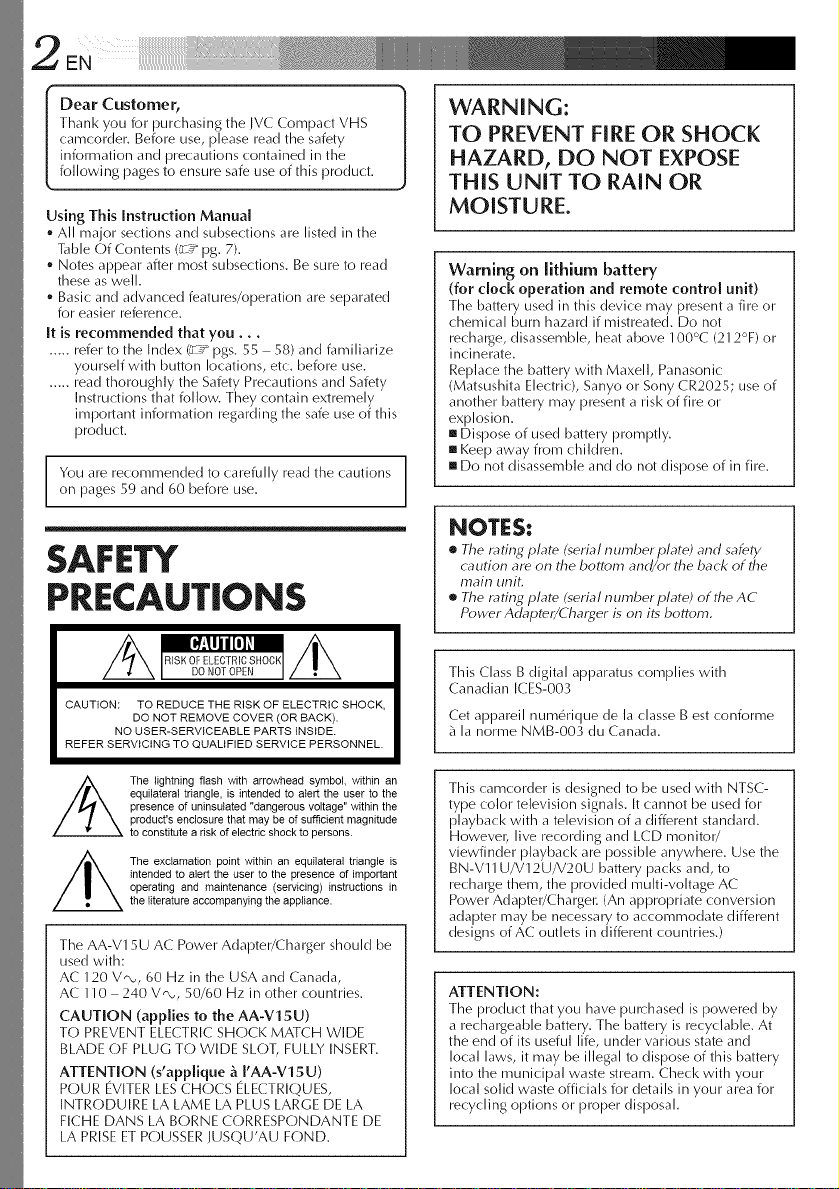
Dear Customer,
Thank you for lourchasing tile JVC Compact VHS
camcorder. Before use, please read the safety
information and precautions contained in the
following pages to ensure safe use of this product.
Using This Instruction Manual
• All major sections and subsections are listed in the
Table Of Contents (:__ 10g.7).
• Notes appeaF after most subsections. Be sure to read
these as well.
• Basic and advanced features/oloeration are separated
for easier reference.
It is recommended that you...
..... refer to the Index C 7 logs. 55 - 58) and familiarize
yourself with button locations, etc, before use.
..... read thoroughly the Safety Precautions and Safety
Instructions that follow. They contain extremely
important information regarding the safe use of this
product.
You are recommended to carefully read the cautions
on pages 59 and 60 before use.
SAFETY
PRECAUTIONS
CAUTION: TO REDUCE THE RISK OF ELECTRIC SHOCK,
REFER SERVICING TO QUALIFIED SERVICE PERSONNEL.
DO NOT REMOVE COVER (OR BACK).
NO USER-SERVICEABLE PARTS INSIDE.
WARNING:
TO PREVENT FIRE OR SHOCK
HAZARD, DO NOT EXPOSE
THIS UNITTO RAIN OR
MOISTURE.
warning on lithium battery
(for clock operation and remote control unit)
The battery used in this device may present a fire or
chemical burn hazard if mistreated. Do not
rechal_ge, disassemble, heat above 100°C (212%) or
incinerate.
Replace the battery with Maxell, Panasonic
(Matsushita Electric), Sanyo or Sony CR2025; use of
another battery may present a Fisk of fire or
explosion.
mDispose of used battery promptly,
mKeep away from children,
g Do not disassemble and do not dispose of in fire,
NOTES:
• The rating plate (serial number plate) and safety
caution are on the bottom and/or the back of the
main unit,
e The rating plate (serial number plate) of the AC
Power Adbpter/Charger is on its bottom,
This Class B digital apparatus complies with
Canadian ICES-003
Cet appareil num6rique de la classe Best confon_ne
_ la norme NMB-003 du Canada.
The lightning flash with arrowhead symbol, within an
equilateral triangle, is intended to alert the user to the
presence of uninsulated "dangerous voltage" within the
product's enclosure that may be of sufficient magnitude
to constitute a risk of electric shock to persons.
The exclamation point within an equilateral triangle is
intended to alert the user to the presence of important
operating and maintenance (servicing) instructions in
the literature accompanying the appliance.
The AA-V15U AC Power Adapter/Charger should be
used with:
AC 120 V_, 60 Hz in the USA and Canada,
AC 110 - 240 V,, 50/60 Hz in other countries.
CAUTION (applies to the AA-V15U)
TO PREVENT ELECTRIC SHOCK MATCH WIDE
BLADE OF PLUG TO WIDE SLOT, FULLY INSERT.
ATTENTION (s'applique fi.I'AA-Vl 5U)
POUR EVITER LES CHOCS ELECTRIQUES,
INTRODUIRE LA LAME LA PLUS LARGE DE LA
FICHE DANS LA BORNE CORRESPONDANTE DE
LA PRISE ET POUSSER IUSQU'AU FOND.
This camcorder is designed to be used with NTSC-
type color television signals. It cannot be used for
playback with a television of a different standard,
However, live recording and LCD monitor/
viewfinder playback are possible anywhere, Use the
BN-Vll U/V12U/V20U battery packs and, to
recharge them, the provided multi-voltage AC
Power Adaloter/Chargel_ (An appropriate conversion
adaloter may be necessary to accommodate different
designs of AC outlets in different countries.)
ATTENTION:
The product that you have pul_:hased is powered by
a rechargeable battery. The battery is recyclable. At
the end of its useful life, under various state and
local laws, it may be illegal to dispose of this battery
into the municipal waste stream, Check with your
local solid waste officials for details in your area for
recycling options or proper disposal.
IMPORTANTPRODUCT
SAFETYINSTRUCTIONS
Electrical energy can perform many useful functions.
But improper use can result in potential electrical
shock or fire hazards. This product has been
engineered and rnanufactured to assure your
personal safety. In order not to defeat time built-in
safeguards, observe the following basic rules for its
installation, use and servicing.
ATTENTION:
Follow and ()bey all warnings and instructions
marked on your product and its operating instruc-
tions. For your safety, please read all timesafetyand
operating instructions before you operate this
product and keep this manual for future reference.
INSTALLATION
1. Grounding or Polarization
(A) Your product may be equipped with a polarized
alternating-current line plug (a plug having one blade
wider than the other). This plug will fit into the
power outlet only one way. This is a safety feature.
If you are unable to insert the plug fully into the
outlet, try reversing the plug. Ifthe plug should still
fail to fit, contact your electrician to replace your
obsolete outlet. Do not defeat the safety purpose of
the polarized plug.
(B) Your product may be equipped with a 3-wire
grounding-type plug, a plug having a third (ground-
ing) pin. This plug will only fit into a grounding-type
power outlet. This is a safety feature.
If you are unable to insert the plug into the outlet,
contact your electrician to replace your obsolete
outlet. Do not defeat the safety purpose of the
grounding-type plug.
2. Power Sources
Operate your product only from the type of power
source indicated on the rnarl<ing label. If you are not
sure of the type of power supply to your home, consult
your product dealer or local power company. If your
product is intended to operate from battery powel; or
other sources, refer to the operating instructions.
3, Overloading
Do not overload wall outlets, extension cords, or integral
convenience receptacles as this can result in a risk of fire
or electric shock.
4. Power Cord Protection
Power supply cords should be routed so that they are
not likely to be walked on or pinched by items placed
upon or against them, paying particular attention to
cords at plugs, convenience receptacles, and the point
where they exit from the product.
5. Ventilation
Slots and openings in the cabinet are provided for
ventilation. To ensure reliable operation of the product
and to protect it from overheating, these openings must
not be blocked or covered.
• Do not block the openings by placing the product on a
bed, sofa, rug or other similar surface.
• Do not place the product in a built-in installation such
as a bookcase or rack unless proper ventilation is
provided or the manufacturer's instructions have been
adhered to.
6. Wall or Ceiling Mounting
The product should be mounted to a wall or ceiling only
as recommended by the rnanufacturel:
ANTENNA INSTALLATION
INSTRUCTIONS
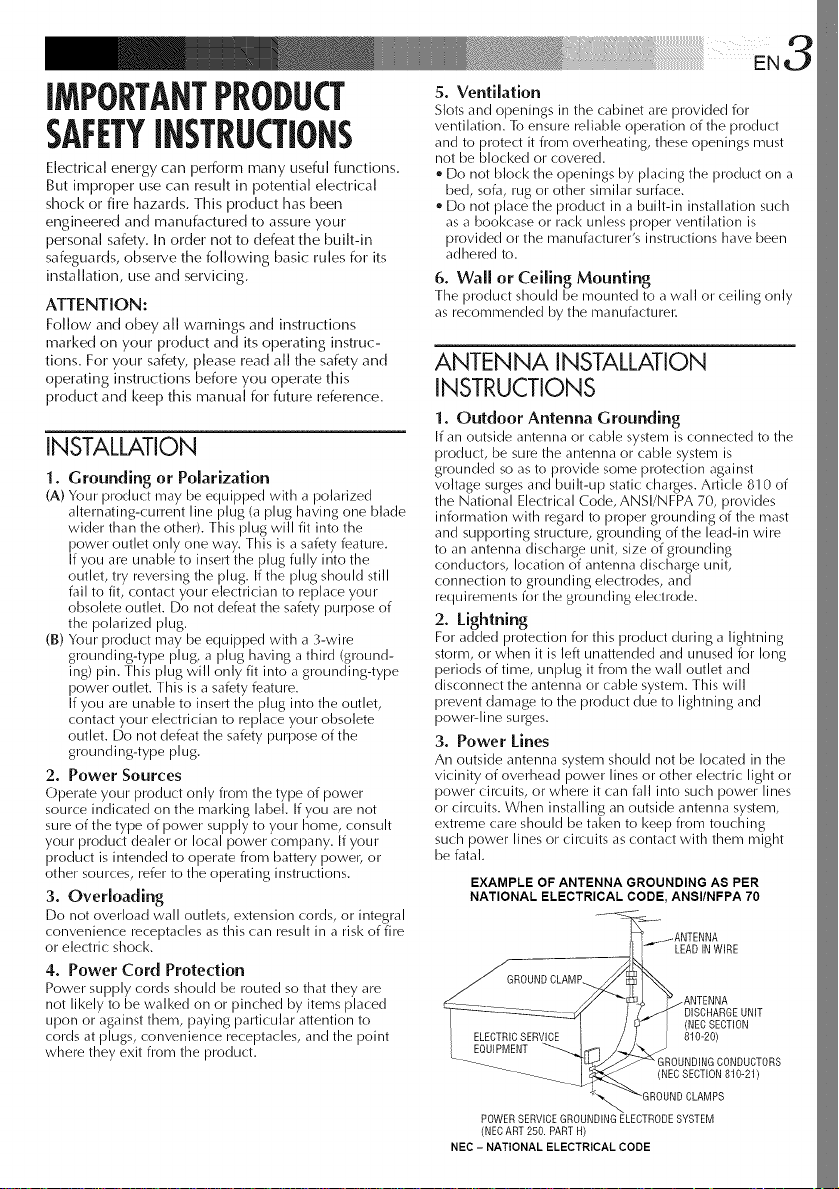
1. Outdoor Antenna Grounding
If an outside antenna or cable system is connected to the
product, be sure the antenna or cable system is
grounded so as to provide some protection against
voltage surges and built-up static chalges. Article 810 of
the National Electrical Code, ANSI/NFPA 70, provides
information with regard to proper grounding of the mast
and supporting structure, grounding of the lead-in wire
to an antenna discharge unit, size of grounding
conductors, location of antenna dischaige unit,
connection to grounding electrodes, and
requiremerlts for the grourlding electrode.
2. Lightning
For added protection for this product during a lightning
storm, or when it is left unattended and unused for long
periods of time, unplug it from the wall outlet and
disconnect the antenna or cable system. This will
prevent damage to the product due to lightning and
poweMine surges.
3. Power Lines
An outside antenna system should not be located in the
vicinity of overhead power lines or other electric light or
power circuits, or where it can fall into such power lines
or circuits. When installing an outside antenna system,
extreme care should be taken to keep from touching
such power lines or circuits ascontact with them might
be fatal.
EXAMPLE OF ANTENNA GROUNDING AS PER
NATIONAL ELECTRICAL CODE, ANSI/NFPA 70
LEADINWIRE
.ANTENNA
DISCHARGEUNIT
ELECTRICSERVICE
EOUIPMENT
(NECSECTION
810-20)
GROUNDINGCONDUCTORS
(NECSECTION810-21)
POWERSERVICEGROUNDINGELECTRODESYSTEM
(NECART250.PARTH)
NEC - NATIONAL ELECTRICAL CODE
4 ENq iii ....
USE SERVICING
1. Accessories
To avoid personal injury:
e Do not place this product on aimunstable cart,
stand, tripod, bracket or table. It may fall, causing
serious injury to a child or adult, and serious
damage to timeproduct.
Use only with a cart, stand, tripod, bracket, or table
recommended by the manufacturer or sold with the
product.
Use a mounting accessory recommended by the
manufacturer and follow the manufacturer's
instructions for any mounting of timeproduct.
Do not try to roll a cart with small casters across
thresholds or deep-pile carpets.
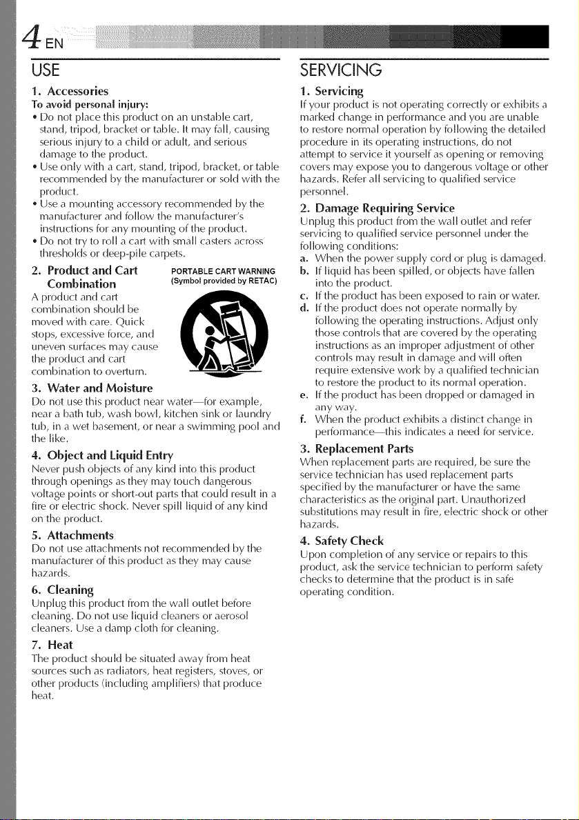
2. Product and Cart PORTABLECARTWARNING
Combination (Symbol provided by RBTAC)
A product and cart
combination should be
moved with care. Quick
stops,excessive force, and
uneven surfaces may cause
the product and cart
combination to overturn.
3. Water and Moisture
Do not use this product near water for example,
near a bath tub, wash bowl kitchen sink or laundry
tub, in a wet basement, or near a swimming pool and
the like.
4. Object and Liquid Entry
Never push objects of any kind into this product
through openings as they may touch dangerous
voltage points or short-out parts that could result in a
fire or electric shock. Never spill liquid of any kind
on the product.
5. Attachments
Do not use attachments not recommended by the
manufacturer of this product as they may cause
hazards.
6. Cleaning
Unplug this product from the wall outlet before
cleaning. Do not use liquid cleaners or aerosol
cleaners. Use a damp cloth for cleaning.
7. Heat
Timeproduct should be situated away from [meat
sources such as radiators, [meatregisters, stoves, or
other products (including amplifiers) that produce
[meat.
I. Servicing
If your product is not operating correctly or exhibits a
marked change in performance and you are unable
to restore normal operation by following timedetailed
procedure in itsoperating instructions, do not
attempt to service it yourself as opening or removing
covers may expose you to dangerous voltage or other
hazards. Refer all servicing to qualified service
personnel.
2. Damage Requiring Service
Unplug this product from the wall outlet and refer
servicing to qualified service personnel under the
folk)wing conditions:
a. When the power supply cord or plug is damaged.
b. If liquid has been spilled, or objects have fallen
into the product.
c. If the product has been exposed to rain or water.
d. If timeproduct does not operate normally by
folk)wing timeoperating instructions. Adjust only
those controls that are covered by timeoperating
instructions as aimimproper adjustment of other
controls may result in damage and will often
require extensive work by a qualified technician
to restore the product to its normal operation.
e. If timeproduct has been dropped or damaged in
any way.
f. When the product exhibits a distinct change in
performance this indicates a need for service.
3. Replacement Parts
When replacement parts are required, be sure the
service technician has used replacement parts
specified by the manufacturer or have the same
characteristics as the original part. Unauthorized
substitutions may result in fire, electric shock or other
hazards.
4. Safety Check
Upon completion of any service or repairs to this
product, ask timeservice technician to perform safety
checks to determine that the product is in safe
operating condition.
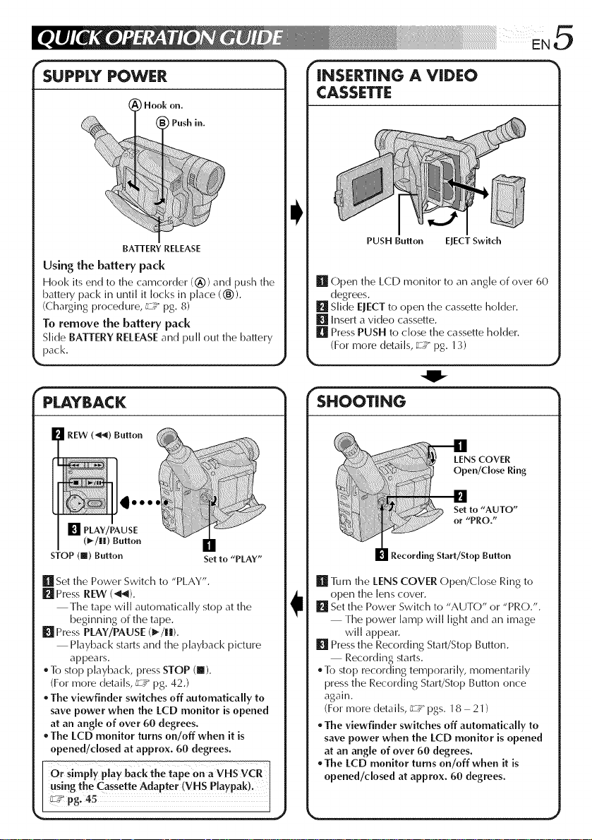
SUPPLY POWER
Hook on.
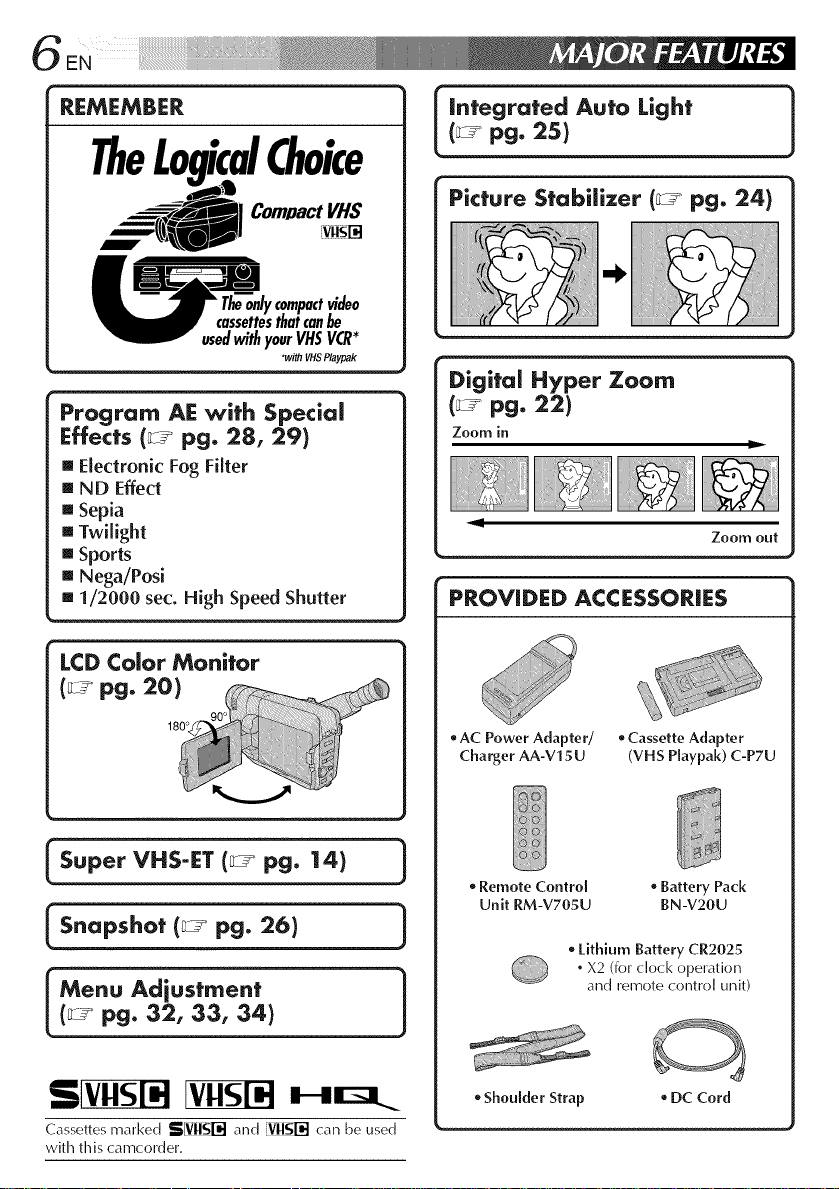
INSERTING A VIDEO
CASSETTE
PPush in.
BATTERY RELEASE
Using the battery pack
Hook its end to the camcorder (_)) and push the
battery pack in until it locks in place (®).
(Charging procedure, _zT pg. 8)
To remove the battery pack
Slide BATTERYRELEASEand puII out timebattery
pack.
r _- -_
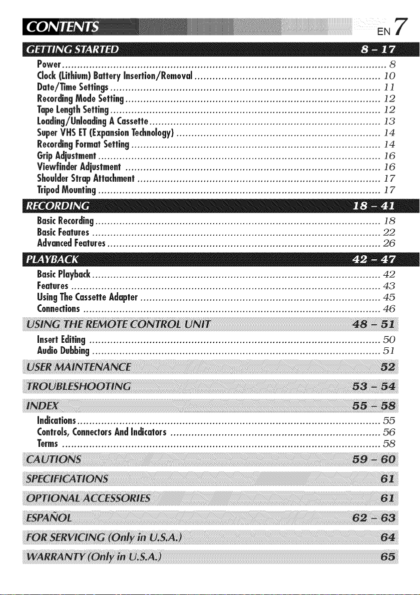
PLAYBACK
(_-/lll) Button
STOP (lI) Button
[] SettimePower Switch to "PLAY".
l_l PressREW (_).
Timetape wiI[ automatically stop at the
beginning of timetape.
[] PressPLAY/PAUSE (1_/!1).
Playback starts and the playback picture
appears.
To stop playback, press STOP (I).
(For more details, _ pg. 42.)
The viewfinder switches off automatically to
save power when the LCD monitor is opened
at an angle of over 60 degrees.
The LCD monitor turns on/off when it is
opened/dosed at approx. 60 degrees.
Orsim y play back the tape on a VHS VCR
usingthe Cassette Adapter (VH S Playpak)_I
_ pg. 45 I
Set to "PLAY"
PUSH Button EJECTSwitch
[] Open time LCD monitor to an angle of over 60
degrees.
[] Slide EJECT to open the cassette holder.
[] Insert a vide() cassette.
[] Press PUSH to dose the cassette holder.
(For more details, _:Y" pg. 13)
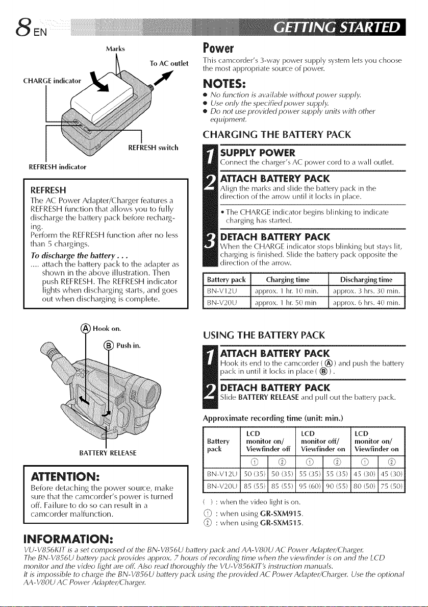
SHOOTING
S COVER
en/CioseRing
to "AUTO"
[ or "PRO,"
Recording Start/Stop Button
[] ]]mmtimeLENSCOVER Open/Close Ring to
open the lens cover.
[] Setthe Power Switch to "AUTO" or "PRO.".
Timepower lamp will light and an image
will appeal.
[] PresstimeRecording Start/Stop Button.
Recording starts.
To stop recording temporarily, momentarily
press timeRecording Start/Stop Button once
again.
(For more details, _7 pgs. 18 21)
The viewfinder switches off automatically to
save power when the LCD monitor is opened
at an angle of over 60 degrees.
The LCD monitor turns on/off when it is
opened/closed at approx. 60 degrees.
J
¸¸¸¸¸¸¸¸¸¸¸¸¸¸¸¸i¸i¸i¸i¸i¸i¸i¸i¸i¸i¸i¸i¸i¸i¸i¸i¸i¸i¸i¸i¸i¸1%¸¸ ii i¸¸¸/ ¸"¸ ¸"¸ _ .... _'
REMEMBER
TheLogicalChoice
(_ pg. 25)
I integrated Auto Light 1
Com/JactVHS
compactvideo
thaicanbe
usedwithyourVHSVCR*
p • •
rogram AE with Special
_vithVHSPlaypak
Effects (_ pg. 28, 29)
[] ElectronicFog Filter
[] ND Effect
[] Sepia
[] Twilight
[] Sports
[] Nega/Posi
[] 1/2000 sec. High Speed Shutter
LCD Color Monitor
(_ pg. 20)
180°
Picture Stabilizer (_-_ pg. 24)
Digital Hyper Zoom
Zoom in
Zoom out
PROVIDED ACCESSORIES
oAC Power Adapter/ oCassette Adapter
Charger AA-V15U (VHS Playpak) C-P7U
Super VHS-ET (_°_ pg. 14) 1
[s.op,ho,pg.26t ]
(_-_ pg. 32, 3:3, 34)
Cassettes marked SIVNI$1-_I and VnNl--'d can be used
with this camcorder.
Remote Control , Battery Pack
Unit RM-V705U BN-V20U
o Lithium Battery CR2025
. X2 (for dock operation
and remote control titbit)
• Shoulder Strap • DC Cord
Power............................................................................................................ 8
Clock(Lithium)BatteryInsertion/Removal.............................................................. ] 0
Date/TimeSettings.......................................................................................... ] ]
RecordingModeSetting..................................................................................... ] 2
TapeLengthSetting.......................................................................................... 12
Loading/UnloadingACassette............................................................................. 13
SuperVHSET(ExpansionTechnology).................................................................... 14
RecordingFormatSetting................................................................................... 14
GripAdjustment.............................................................................................. 16
View|inderAdjustment..................................................................................... 16
ShoulderStrapAttachment................................................................................. ] 7
TripodMounting.............................................................................................. ] 7
BasicRecording............................................................................................... 18
BasicFeatures................................................................................................ 22
AdvancedFeatures........................................................................................... 26
BasicPlayback................................................................................................ 42
Features....................................................................................................... 43
UsingTheCassetteAdapter................................................................................ 45
Connections................................................................................................... 46
7
InsertEditing................................................................................................. 50
AudioDubbing................................................................................................ 51
Indications..................................................................................................... 55
Controls,ConnectorsAndIndicators...................................................................... 56
Terms.......................................................................................................... 58
8ENi_ii_ii!i!_i!_i!_i!_i!_i!_i!_i!_i!_i!_i!_i!_i!_i!_i!_i!_i!_i!_i!_i!_i!_i!_i!_i!_i!_i!_i!_i!_i!_i!_i!i!i!iiiiiiiiHi_i_iiii!i!!!i!!!i!_i_....
Marks
To AC outlet
CHARGE indicator I
REFRESHswitch
REFRESH h_dicator
REFRESH
The AC Power Adapter/Charger features a
REFRESH function that allows you to fully
discharge the battery pack before recharg-
ing.
Perform the REFRESH function after no less
than 5 chargings.
To discharge the battery...
.... attach the battery pack to the adapter as
shown in the above illustration. Then
push REFRESH. The REFRESH indicator
lights when discharging starts, and goes
out when discharging is complete.
i Hook on.
Push in.
Power
This camcorder's 3-way power supply system lets you choose
the most appropriate source of power.
NOTES:
• No function is awd/ab/e without power supply.
• Use only the specified power supply.
• Do not use provk/ed power supply units with other
erluilJment.
CHARGING THE BATTERY PACK
SUPPLY POWER
Connect the charger% AC power cord to a wall outlet.
ATTACH BATTERYPACK
Align the marl<s and slide the battery pack in the
direction of the arrow until it locks in place.
* The CHARGE indicator begins blinking to indicate
charging has started.
DETACHBATTERYPACK
When the CHARGE indicator stops blinking but stays lit,
charging is finished. Slide the battery pack opposite the
direction of the arrow.
Battery pack Charging time Discharging time
BN-V12U approx. 1 hi: 10 rain. approx. 3 hrs. 30 rain.
BN-V20U approx. 1 his50 rain approx. 6 hrs. 40 rain.
USING THE BATTERY PACK
ATTACH BATTERYPACK
Hool< its end to the camcorder ((_)) and push the battery
pack in until it Iocl<s in place ( (_)).
DETACHBATTERY PACK
Slide BATTERY RELEASEand pull out the battery pack,
Approximate recording time (unit: rain,)
LCD LCD LCD
BATTERY RELEASE
Battery monitor on/ monitor off/ monitor on/
pack Viewfinder off Viewfinder on Viewfinder on
d) © d) © d) ©
ATTENT|ON:
Before detaching the power source, make
sure that the camcorder's power is turned
off. Failure to do so can result in a
camcorder malfunction.
BN-V12U 50 (35) 50 (35) 55 (35) 55 (35) 45 (30) 45 ('gO)
BN-V20U 85 (55) 85 (55) 95 (60) 90 (55) 80 (50) 75 (50)
( ) : when the video light is on.
: when using GR-SXM915.
_i_ : when using GR-SXM515.
iNFORMATiON:
VU-VS_6KIT is a set composed of the BN-V856U battery pack and AA-VSOU AC Power Adapter/Cha_4er.
The BN-VS S6U battery pack provides aplJrox. 7 hours of recording time when the viewfinder is on and the LCD
monitor and the video light are off. Also read thoroughly the VU-V856KIT9 instruction manuals.
It is impossible to charge the BN-V856U battery pack using the provided AC Power Adapter/(harger. Use the optional
AA-VSOU AC Power Adapter/Charger.
...... I!iiii iii ill¸EN9
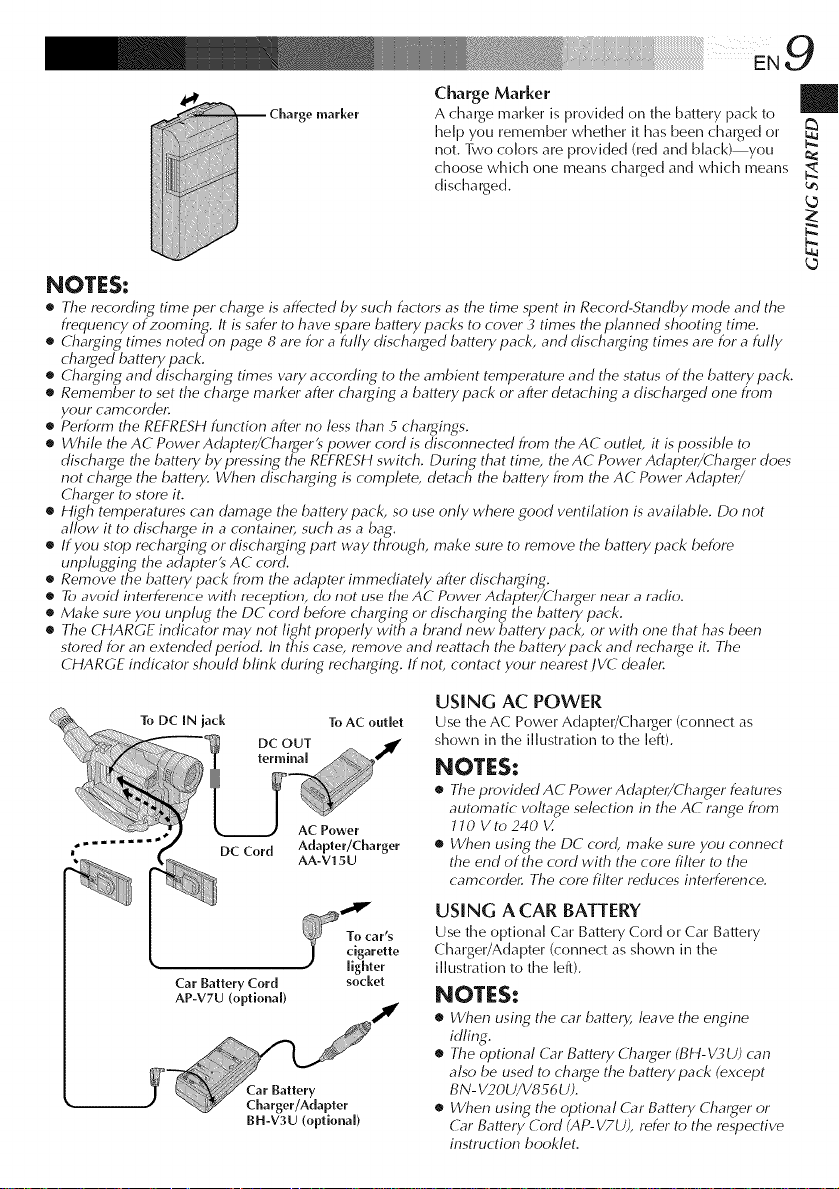
Charge Marker
A charge marker is provided on the battery pack to
help you remember whether it has been charged or
not. Two colors are provided (red and black) you
choose which one means charged and which means
discharged.
_ Charge marker
NOTES:
• The recording time per charge is affected by such factors as the time spent in Record-Standby mode and the
frequency of zooming. It is safer to have spare battery packs to cover 3 times the plam_ed shooting time.
• Charging times noted on page 8 are for a fully discharged batterypack, and discharging times are for a fully
charged battery pack.
• Charging and discharging times w_ry according to the ambient temperature and the status of the battery pack.
• Remember to set the charge marker after charging a batterypack or after detaching a discharged one from
your camcordel:
• Perform the REFRESH function after no less than 5 chargings.
• While the AC Power Adapter/Charger's power cord is disconnected from the AC outlet, it is possible to
discharge the battery by pressing the REFRESH switch. During that time, the AC Power Adapter/Charger does
not charge the battery. When discharging is complete, detach the battery from the AC Power Adapter/
Charger to store it.
• High temperatures can damage the battery pack, so use only where good ventilation is available. Do not
allow it to discharge in a containel, such as a bag.
• If you stop recharging or discharging part way through, make sure to remove the battery pack before
unplugging the adapterts AC cord.
• Remove the battery pack from the adapter immediately after discharging.
e To avoid intelfelence with reception, do not use the AC Power Adapte_/(hat_er near a radio.
• Make sure you unplug the DC cord before charging or discharging the battery pack.
• The CHARGE indicator may not light properly with a brand new battery pack, or with one that has been
stored for an extended period. In this case, remove and mattach the battery pack and recharge it. The
CHARGE indicator should blink during recharging. If not, contact your nearest JVC dealel:
USING AC POWER
Use the AC Power Adapter/Charger (connect as
shown in the illustration to the left).
NOTES:
• The providedAC PowerAdapter/Charger features
automatic voltage selection in the AC range from
JJO Vto240 V.
• When using the DC cord, make sure you connect
the end of the cord with the core filter to the
camcordel: The core filter reduces interference.
USING A CAR BATTERY
Use the optional Car Battery Cord or Car Battery
Charger/Adapter (connect as shown in the
Car Battery Cord socket
AP-V7U (optional)
BH-V3U (optional)
illustration to the left).
NOTES:
• When using the car battery, leave the engine
idling.
• The optional G_r Battery Charger (BH-_/_,U) can
also be used to charge the battery pack (except
BN- V20U/V856 U).
• When using the optional G_r Battery Charger or
G_r Battery Cord (AP- V7U), refer to the respective
instruction booklet.
k_
N.
k_
]
Battery holder
©-,©
Slot
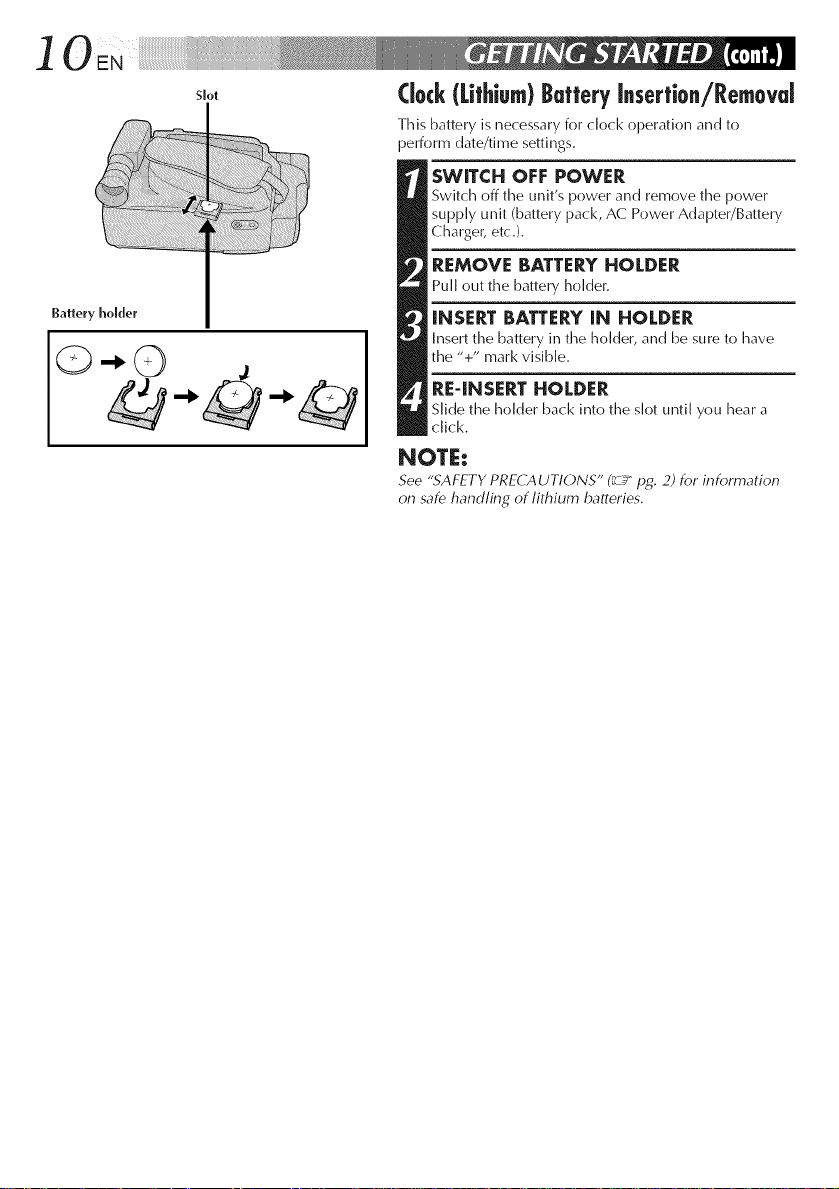
Clock(Lithium)ButteryInsertion/Removal
This battery is necessary for clock operation and to
perform date/time settings.
SWITCH OFF POWER
Switch off time unit's power and remove time power
supply unit (battery pack, AC Power Adapter/Battery
Charger, etc.).
REMOVE BATTERYHOLDER
Pull out the battery holder.
INSERT BATTERY[N HOLDER
Insert time battery in time holder, and be sure to have
the "+" mark visible.
RE4NSERT HOLDER
Slide the holder back into the slot until you hear a
click.
NOTE:
See ".SAFETY PRECAUTIONS" (_ pg. 2) for information
on safe handling of lithium batteries.
]
oo °
• MENU Button
I
Q
Select DIM
Display
O
Power lamp
Power Switch
Menu Screen
DATE/TIME Menu
indication
with AM or PM
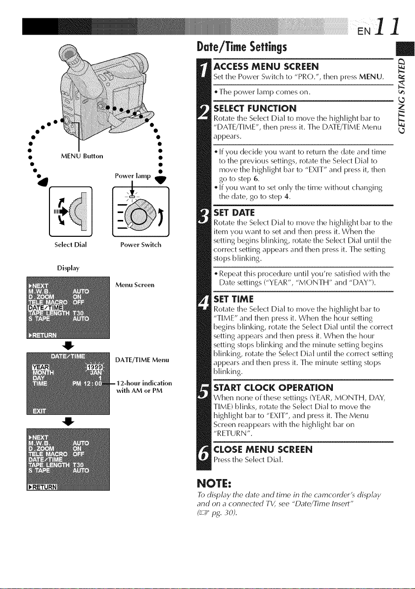
Date/TimeSettings
ACCESSMENU SCREEN
Set the Power Switch to "PRO.", then press MENU.
. Time power lamp comes on.
SELECT FUNCTION
Rotate the Select Dial to move time highlight bar to
"DATE/TIME", then press it. Time DATE/TIME Menu
appears.
If you decide you want to returntime date and time
to the previous settings, rotate the Select Dial to
move time highlight bar to "EXIT" and press it, then
go to step 6.
If you want to set only the time without changing
the date, go to step 4.
SET DATE
Rotate time Select Dial to move time highlight bar to the
item you want to set and then press it. When the
setting begins blinking, rotate the Select Dial until the
correct setting appears and then press it. Time seiling
stops blinking.
Repeat this procedure until you're satisfied with the
Date settings ("YEAR", "MONTH" and "DAY").
SET TIME
Rotate time Select Dial to move the highlight bar to
"TIME" and then press it. When the hour setting
begins blinking, rotate the Select Dial until the correct
setting appears and then press it. When timehour
setting stops blinking and time minute setting begins
blinking, rotate the Select Dial until the correct setting
appears and then press it. Time minute setting stops
blinking.
STARTCLOCK OPERATION
When none of these settings (YEAR, MONTH, DAY,
TIME) blinks, rotate the Select Dial to move the
highlight bar to "EXIT", and press it. Time Menu
Screen reappears with the highlight bar on
"RETURN".
CLOSE MENU SCREEN
Press the Select Dial.
|
NOTE:
To display the date and time in the camcorderts display
and on a connected TV, see "Date/Time Insert"
(_Y pg. 3d).
] 2EN¸ .... o
oo °
• MENU Button
• SP/EP Recording Mode Button
Select Dial
Viewfiuder
Display
0
Power Switch
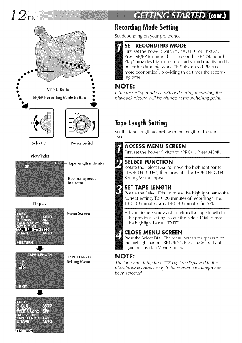
mode
indicator
Menu Screen e If you decide you want to return the tape length to
TAPE LENGTH
Setting Menu
RecordingModeSetting
Set depending on your preference.
First set the Power Switch to "AUTO" or "PRO.".
Press SP/EP for more than 1 second. "SP" (Standard
Play) provides higher picture and sound quality and is
beiler for dubbing, while "EP" (Extended Play) is
SET RECORDING MODE
more economical, providing three times the record-
ins time.
NOTE:
If the recording mode is switched during recording, the
playback picture will be blurred at the switching point.
TapeLengthSetting
Set the tape length according to the length of the tape
used.
ACCESS MENU SCREEN
Firstsetthe PowerSwitchto "PRO.". PressMENU.
SELECT FUNCTION
Rotate the Select Dial to move the highlight bar to
"TAPE LENGTH", then press it. The TAPE LENGTH
Setting Menu appears.
SETTAPE LENGTH
Rotate the Select Dial to move the highlight bar to the
correct setting. T20=20 minutes of recording time,
T30=30 minutes, and T40=40 minutes (in SP).
the previous setting, rotate the Select Dial to move
the highlight bar to "EXIT".
CLOSE MENU SCREEN
Press the Select Dial. The Menu S(-reen reappears with
the highlight bar on "RETURN". Press the Select Dial
gain to close the Menu Screen.
NOTE:
The tape remaining time (_ pg. 79) displayed in the
viewfinder is correct only if the correct tape length has
been selected.
0
PUSH Bullon
Erase Proledion
Casselle holder
I
EJECT Swilch
Gear
Turn to lake
up slack.
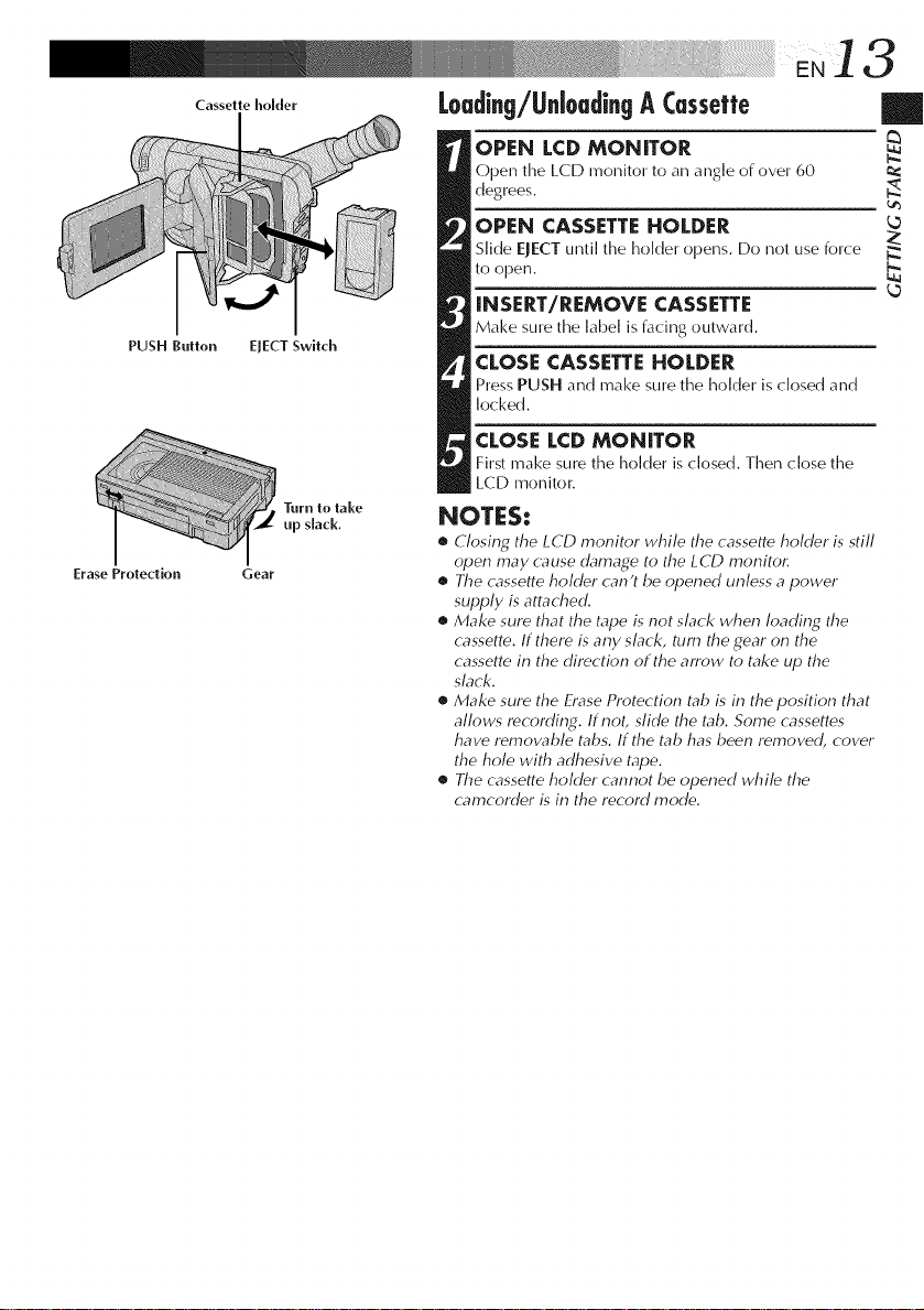
Loading/UnloadingA Cessette
OPEN LCD MONITOR
Open the LCD monitor to an angle of over 60
d%rees.
OPEN CASSETTE HOLDER
Slide EJECT until the holder ()pens. Do not use force
to open.
INSERT/REMOVE CASSETTE
Make snre the label is facing outward.
CLOSE CASSETTE HOLDER
Press PUSH and make snre the holder is closed and
locked.
CLOSE LCD MONITOR
First make sure the holder is closed. Then close the
LCD monitor.
NOTES:
• Closing the LCD monitor while the cassette holder is still
open may cause damage to the LCD monitor.
• The cassette holder can't be opened unless a power
supply is attached.
• Make sure that the tape is not slack when loading the
cassette. If there is any slack, turn the gear on the
cassette in the direction of the arrow to take up the
slack.
• Make sure the Erase Protection tab is in the position that
allows recording. If not, slide the tab. Some cassettes
have removable tabs. If the tab has been removed, cover
the hole with adhesive tape.
• The cassette holder cannot be opened while the
cam(order is in the record mode.
|
N.
L_
14 ....
oo °
Z
S-VHS ET Switch I
with S-VHS ET Lamp •
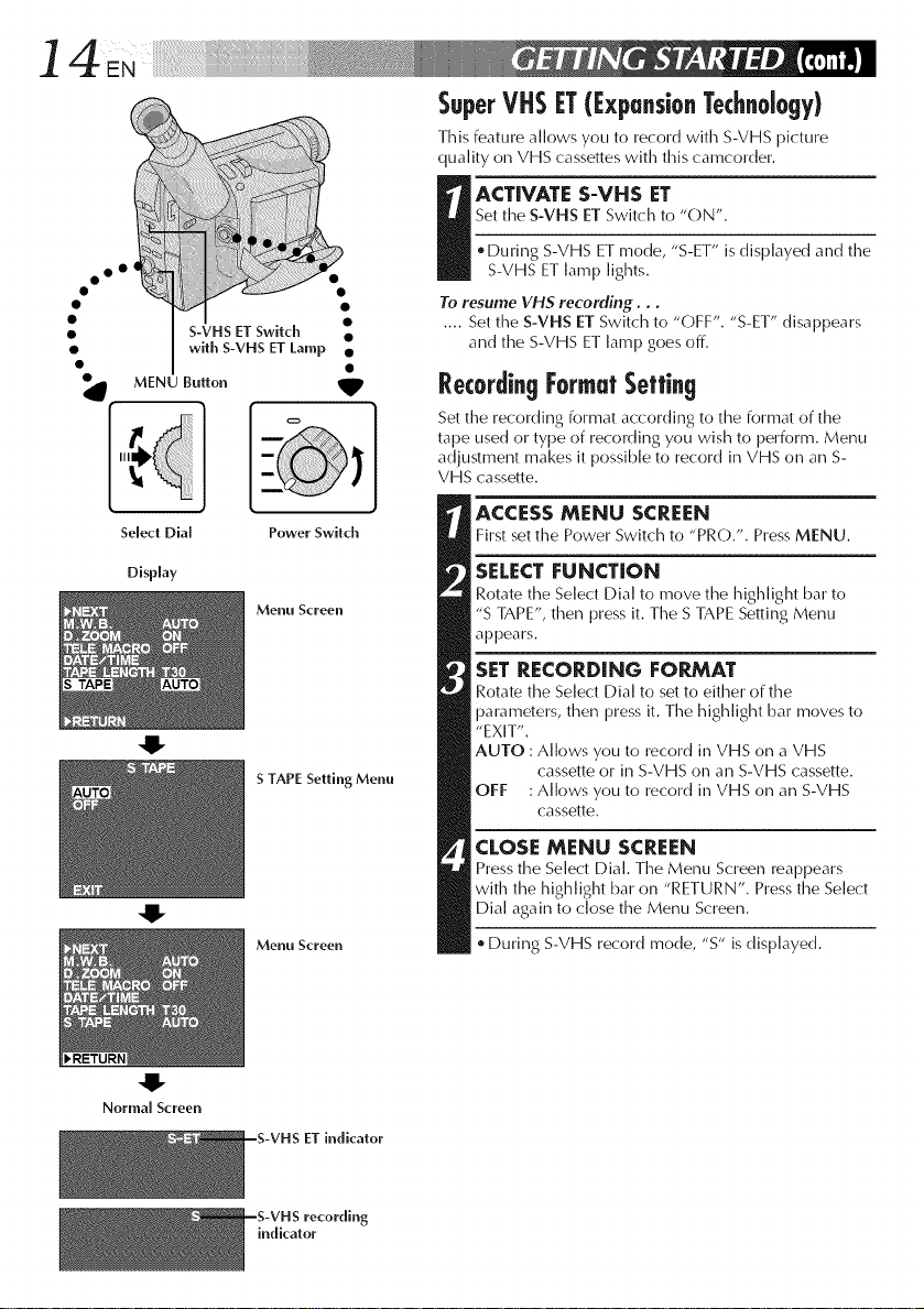
SuperVHSIT([xpansionTechnology)
This feature allows you to record with S-VHS picture
quality on VHS cassettes with this camcorder.
Set the S-VHS ET Switch to "ON".
I ACTIVATE S-VHS ET
. During S-VHS ET mode, "S-ET" is displayed and the
S-VHS ET lamp lights.
To resume VHS recording...
.... Set the S-VHS ET Switch to "OFF". "S-ET" disappears
and the S-VHS ET lamp goes off.
MENU Button _IP
Select Dial
Display
Power Switch
Menu Screen
-U-
S TAPE Setting Menu
4!-
Menu Screen
RecordingFormatSetting
Set the recording format according to the format of the
tape used or type of recording you wish to perform. Menu
adjustment makes it possible to record in VHS on an S-
VHS cassette.
ACCESS MENU SCREEN
First set the Power Switch to "PRO.". Press MENU.
SELECTFUNCTION
Rotate the Select Dial to move the highlight bar to
"S TAPE", then press it. Time S TAPE Setting Menu
appears.
SET RECORDING FORMAT
Rotate the Select Dial to set to either of the
parameters, then press it. Time highlight bar moves to
"EXIT".
AUTO : Allows you to record in VHS on a VHS
cassette or in S-VHS on an S-VHS cassette.
OFF :Allows you to record in VHS on an S-VHS
cassette.
CLOSE MENU SCREEN
Press the Select Dial. TimeMenu Screen reappears
with the highlight bar on "RETURN". Press the Select
Dial again to close the Menu Screen.
. During S-VHS record mode, "S" is displayed.
4!"
Normal Screen
--S-VHS ET indicator
indicator
[]JVC EHG (Extra High Grade) tapes are recommended for superior results.
Use S-Vf t5 tape for storing recordings for an extended period or for recording important scenes, as it
enables higher-quality recording and playback.
[] With some tapes, better picture quality may not be obtained even with S-VHS ET recording. It is
recommended that you do test record beforehand to make sure whether better results can be obtained.
[] If the S-VHS ET mode or recording format is switched during recording, the playback picture will be
blurred at the switching point.
[]It is recommended that tapes recorded in the SP mode on this camcorder be played back on this
cafT]cordeg
[]Noise may appear on-screen when tapes recorded in the EP mode are played back.
[] Tapes recorded in S-WffS or S-VHS ET mode can be played back not only on this camcorder but also on
a Super VHS VCR or a VCR equipped with the SQPB (S-VHS QUASI PLAYBACK) function.
When tapes recorded in S-VHS or S-VHS ET mode are played back on a VCR equipped with the
SQPB (S-VHS QUASI PLAYBACK) function, S-VHS picture quality is not available.
Tapes recorded in S-VHS ET mode cannot be played back on some VCRs, including some JVC VCRs
(eg: HR-S6600U, HR-SCJ 000U, etc.).
[] Tapes recorded in S-VHS or S-VHS ET mode cam_ot be played back correctly on a normal VHS VCR.
[] Ybu can play back S-VHS ET recordings not only on this VCR but also on another VHS VCR equipped
with S- VHS ET.
It is recommended to specifically label S-VHS ET recordings so you can easily distinguish them from
regular VHS recordings.
[] S-VHS ET does not work with S-VHS tapes.
[] To avoid on-screen noise, do not perform Still Playback or Shuttle Search repeatedly.
[] If the picture contains a lot of jitter or noise, use a cleaning cassette.
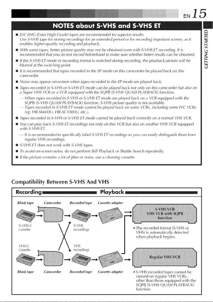
Compatibility Between S-VHS And VHS
Recording_ Playback
BLink tape Camcorder Recorded tape Cassette adapter
S-VHS-C S-VHS
cassette recordings
VHS-C VHS
cassette recordings
BLink tape Camcorder Recorded tape Cassette adapter
The recorded format (S-VHS or
VHS) is automatically detected
when playback begins.
S-VHS recorded tapes cannot be
viewed on regular VHS VCRs,
other than those equipped with the
SQPB (S-VHS QUASI PLAYBACK)
function.
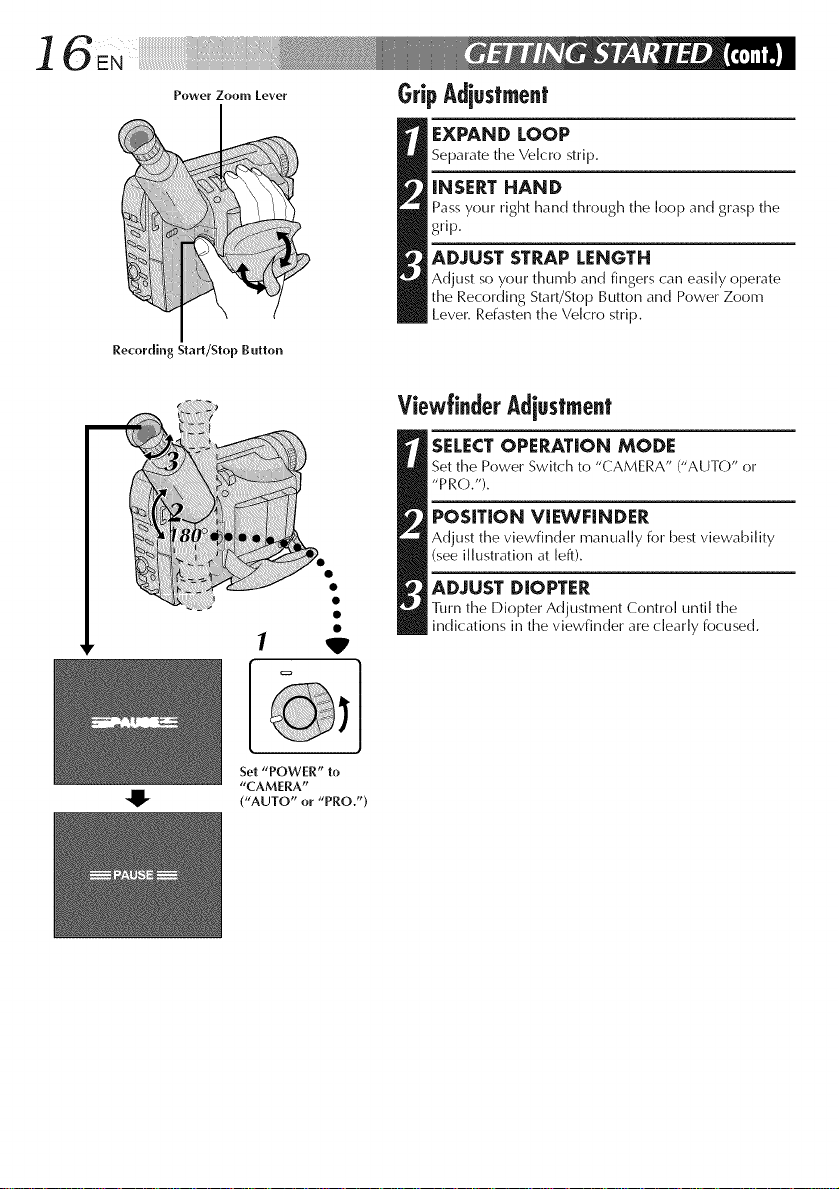
_eworZoo.,_o_or GripAdiuslment
Recording Start/Step Button
1
EXPAND LOOP
Separate the Velcro strip.
iNSERT HAND
Pass your right hand through the loop and grasp the
grip.
ADJUST STRAP LENGTH
Adjust so your thumb and fingers can easily operate
the Recording Start/Stop Button and Power Zoom
Lever. Refasten the Ve[cro strip.
ViewtinderAdiustment
[SELECT OPERATION MODE
Set time Power Switch to "CAMERA" ("AUTO" or
"PRO.").
POSiTiON ViEWFINDER
Adjust the viewfinder manually for best viewability
(see illustration at left).
ADJUST DIOPTER
1]irn time Diopter Adjustment Control until the
indications in the viewfinder are dearly focused.
'W'
Set "POWER" to
"CAMERA"
("AUTO" or "PRO.")
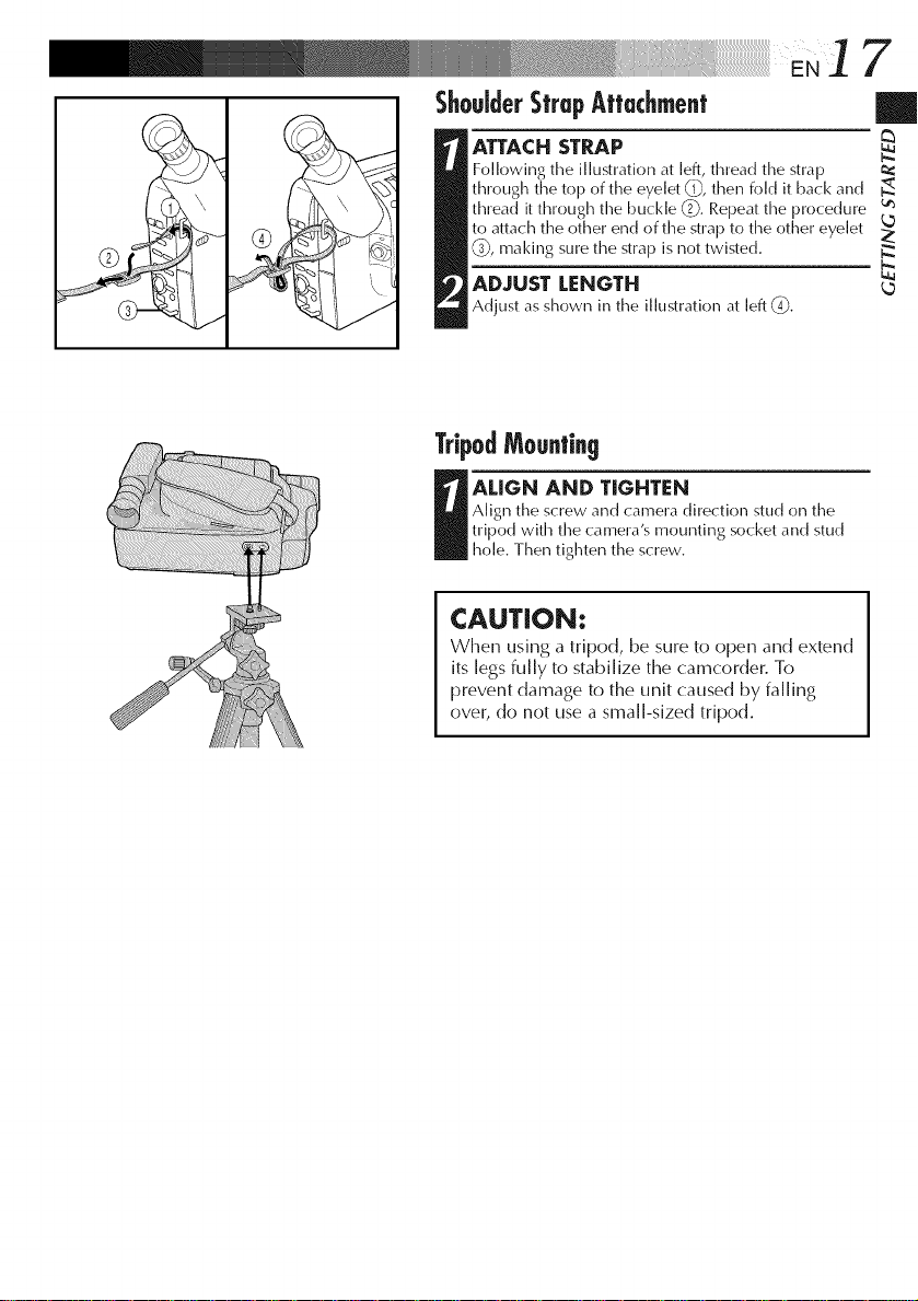
ShouJderSfrupAffachmenf
ATTACH STRAP
Following the illustration at left, thread the strap
through the top of the eyelet 0,_,then fold it back and
thread it through the buckle (2-_.Repeatthe procedure _
to attach the other end of the strap to the other eyelet
(9, making sLirethe strap is not twisted.
ADJUST LENGTH
Adjust as shown in the illustrationat [eft (-O.
TripodMounting
R hole.tripodwith tileAligl_theALlGNThenSCrewandANDtightenCamera'smounting socketalldTlGHTJ_NttleCal_el'as_.rew.directi()l_stud on studthe
CAUTION:
When using a tripod, be sure to open and extend
its legs fully to stabilize the camcorder. To
prevent damage to the unit caused by falling
over, do not use a small-sized tripod.
7
/
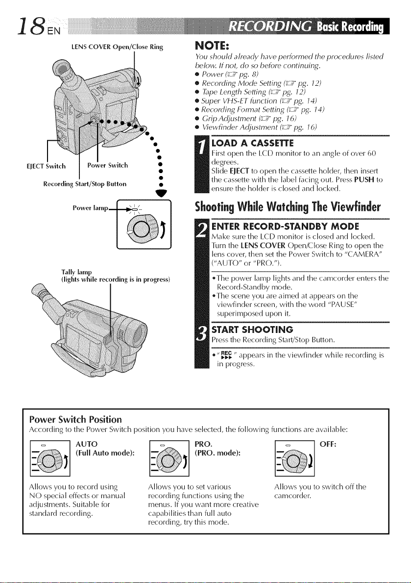
LENS COVER Open/close Ring
EJECT Switch PoWer SWitch
Recording Start/Slop Button
Tally lamp
(lights while recording is in progress)
NOTE:
Ybu should already have performed the procedures listed
below. If not, do so before continuing.
• Power (_ pg. 8)
• Recording Mode Setting (_ pg. J2)
• Tape Length Setting (_ pg. J2)
• Super VHS-ET function (_ pg. J4)
• Recording Format Setting (_ pg. J4)
• Grip Adjustment (_ pg. J 6)
• Viewfinder Adjustment (_ pg. J 6)
First open the LCD monitor to an angle of over 60
degrees.
Slide EJECT to open the cassette holder, then insert
I OAD A CASSETTE
the cassette with the [abe[ facing out. Press PUSH to
V
ensure the holder is closed and locked.
ShootingWhileWatchingTheViewfinder
ENTERRECORD-STANDBY MODE
Make sure the LCD monitor is closed and locked.
Turn the lENS COVER Open/Close Ring to open the
lens cover, then set the Power Switch to "CAMERA"
("AUTO" or "PRO.").
.The power lamp lights and the camcorder enters the
Record-Standby mode.
_The scene you are aimed at appears on the
viewfinder screen, with the word "PAUSE"
superimposed upon it.
STARTSHOOTING
Press the Recording Start/Stop Button.
.,, _REc,, appears in the viewfinder while recording is
in progress.
Power Switch Position
According to the Power Switch position you have selected, the following functions are available:
AUTO PRO. OFF:
(Full Auto mode): (PRO. mode):
Allows you to record using
NO special effects or manual
adjustments. Suitable for
standard recording.
Allows you to set various
recording functions using the
menus. If you want more creative
capabilities than full auto
recording, try this mode.
Allows you to switch off the
camcorder.
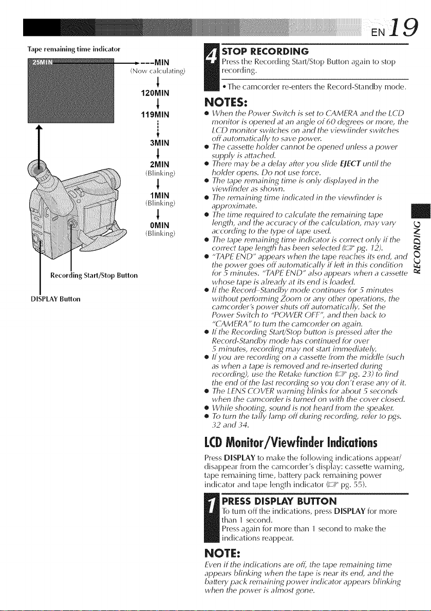
Tape remaining time indicator
Recording Start/Stop Button
DISPLAY Button
(Now calculating)
!
120MIN
119MIN
t
3MIN
2MIN
(Blinking)
1MIN
(Blinking)
1
OMIN
(Blinking)
19
Press the Recording StaWStop Button again to stop
recording.
I TOP RECORDING
, Timecamcorder re-enters the Record-Standby mode.
NOTES:
• When the Power Switch is set to CAMERA and the LCD
monitor is opened at an angle of 60 degrees or more, the
LCD monitor switches on and the viewfinder switches
off automatically to save powel:
• The cassette hokler cmmot be opened unless a power
supply is attached.
• There may be a delay after you slide EJECT until the
holder opens. Do not use force.
• The tape remaining time is only displayed in the
viewfinder as shown.
• The remaining time indicated in the viewfinder is
approximate.
• The time required to calculate the remaining tape
length, and the accuracy of the calculation, may vary
according to the type of tape used.
• The tape remaining time indicator is correct only if the
correct tape length has been selected _ pg. 12).
• "TAPE END" appears when the tape reaches its end, and
the power goes off automatically if left in this condition
for 5 minutes. "TAPE END" also appears when a cassette
whose tape is already at its end is loaded.
• If the RecordStandby mode continues for 5 minutes
without performing Zoom or any other operations, the
camcorder'spower shuts off automatically. Set the
Power Switch to "POWER OFF", and then back to
"CAMERA" to turn the camcorder on again.
• If the Recording Start/Stop button is pressed after the
Record-Standby mode has continued for over
5 minutes, recordiny_ may not start immediately.
• If you are recordingon acassette from the middle (such
as when a tape is removed and re-inserted during
recording), use the Retake function _zg pg. 23) to find
the end of the last recording so you don't erase any of it.
• The LENS COVER warning blinks for about 5 seconds
when the camcorder is turned on with the cover closed.
• While shooting, sound is not heard from the speaker.
• To turn the tally lamp off during recording, refer to pgs.
,32 and ,34.
|
LCDMonitor/Viewfinderindications
Press DISPLAY to make the following indications a ppea r/
disappear from time camcorder's display: cassette warning,
tape remaining time, battery pack remaining power
indicator and tape length indicator (_,2_pg. 55).
l-o turn off time indications, press DISPLAY for more
than 1 second.
I RESS DISPLAY BUTTON
Press again for more than 1 second to make the
indications reappear.
NOTE:
Even if the indications are off, the tape remaining time
appears blinking when the tape is near its end, and the
battery pack remaining power indicator appears blinking
when the power is almost gone.
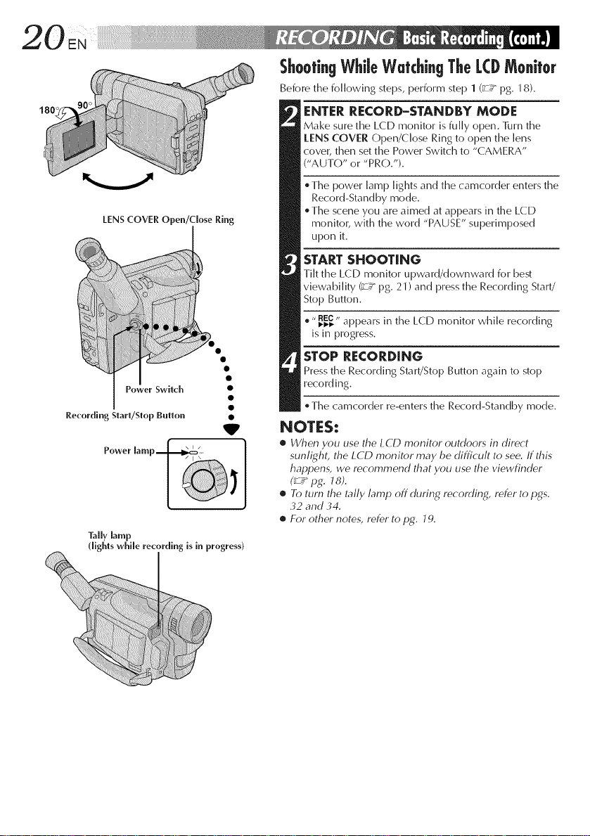
180'
LENS COVER Open/close Ring
V
Tally lamp
dights while recording is in progress)
Shoofi.gWhileWatchi.gTheLCDMo.itor
Before the following steps, perform step 1 (_ pg. 18).
ENTERRECORD-STANDBY MODE
Make sure the LCD monitor is fully open. 111rn the
tENS COVER Open/Close Ring to open the lens
cover, then set the Power Switch to "CAMERA"
("AUTO" or "PRO.").
The power lamp lights and the camcorder enters the
Record-Standby mode.
The scene you are aimed at appears in the LCD
monitor, with the word "PAUSE" superimposed
upon it.
STARTSHOOTING
Tilt the LCD monitor upward/downward for best
viewability (_ pg. 21) and press the Recording Start/
Stop Button.
® " I_I_REC,, appears in the LCD monitor while recording
is in progress.
STOP RECORDING
Press the Recording Start/Stop Button again to stop
recording.
The camcorder re-enters the Record-Standby mode.
NOTES:
• When you use the LCD monitor outdoors in direct
sunfighL the LCD monitor may be difficult to see. If this
happens, we recommend that you use the viewfinder
(_ pg. J 8).
• To turn the tally lamp offdurir N recording, refer to pgs.
32 and 34.
• For other notes, refer to pg. 19.
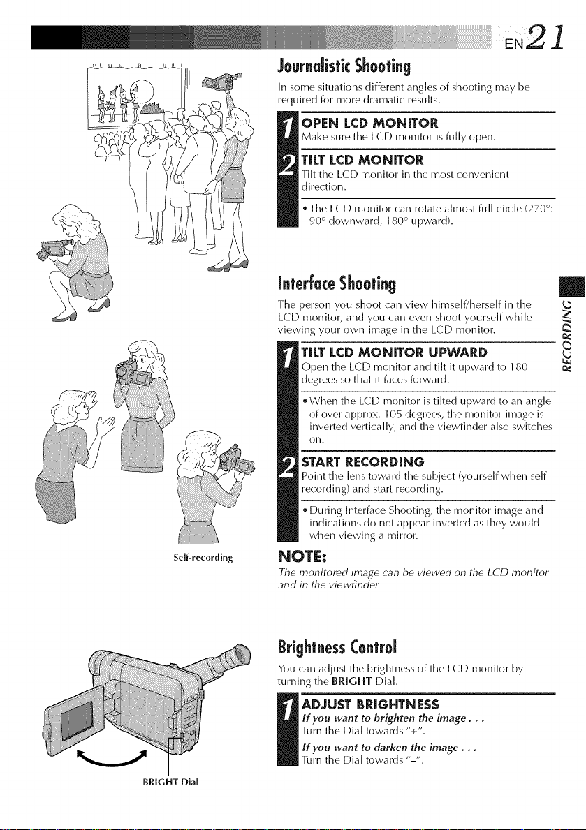
JournalisticShooting
Insome situations different angles of shooting may be
required for more dramatic results.
Make SLIre the LCD monitor is fully open.
TILT LCDMONITOR
Tilt time L(:D monitor in the most convenient
direction.
OPEN LCD MONITOR
* Time LCD monitor calm rotate almost full circle (270°:
90 ° downward, 180 ° upward).
2 ]
Self-recording
InterJuceShooting
The person you shoot can view hh_self/herself in the
L(:D monitor, and you can even shoot yourself while
viewing your own image in the LCD monitor.
TILTLCDMONITOR UPWARD
Open time LCD monitor and tilt it upward to 180
degrees so that it faces forward.
When the LCD monitor is tilted upward to an angle
of over approx. 105 degrees, time monitor image is
inverted vertically, and the viewfinder also switches
olm.
START RECORDING
point the lens toward the subject (yourself when self-
recording) and start recording.
During Interface Shooting, the monitor image and
indications do not appear inverted as they would
when viewing a mirror.
NOTE:
The monitored image can be viewed on the L(?D monitor
and in the viewfind¢
BrightnessControl
You can adjust the brightness of the LCD monitor by
turningthe BRIGHT Dial.
|
2:
BRIGHT Dial
If you want to brighten the image, , ,
]_mm the Dial towards "+".
I DJUST BRIGHTNESS
If you want to darken the image, ,,
]imm the Dial towards "-".
 Loading...