

Page 1
COMPACT VHS CAMCORDER
VICTOR COMPANY OF JAPAN, LIMITED
VIDEO DIVISION
S40894
GR-FXM37EG, SXM607EG/EK
GR-FXM37EG, SXM607EG/EK
SPECIFICATIONS
Camcorder
General
No. 86589
Format : S-VHS (GR-SXM607)
Power source : DC 11 V
Power consumption
LCD monitor* off,
viewfinder on : 4.0 W
LCD monitor* on,
viewfinder off : 4.5 W
Video light** : 3.0 W
* Models equipped with LCD monitor only.
** GR-SXM607 only.
Signal system : PAL-type
Video recording system
Luminance : FM recording
Colour : Converted sub-carrier
Cassette :
Tape speed
SP : 23.39 mm/sec.
LP : 11.70 mm/sec.
Recording time (max.)
SP : 60 minutes
LP : 120 minutes
Operating
temperature :0°C to 40°C
VHS PAL standard
(Using AC Adapter)
DC 6 V
(Using battery pack)
direct recording
Conforms to VHS standard
(with EC-60 cassette)
VHS
PAL
625
(The specifications shown pertain specifically to the model GR-SXM607EG/FXM37EG)
/ cassette
Operating humidity : 35% to 80%
Storage temperature : –20°C to 50°C
Weight : Approx. 910 g (GR-SXM607)
Dimensions : 200 mm x 112 mm x 118 mm
(W x H x D)
* Models equipped with LCD monitor only.
Pickup : 1/4" format CCD
Lens : F1.6, f = 3.9 mm to 62.4 mm,
Viewfinder : Electronic viewfinder with 0.5"
White balance
adjustment : Auto/Manual adjustment
LCD monitor : 3" diagonally measured,
(models equipped with
LCD monitor only)
Speaker : Monaural
(models equipped with
LCD monitor only)
Connectors
JLIP/EDIT : ø3.5 mm, 4-pole, mini-head
Video : 1 V (p-p), 75 Ω unbalanced,
Approx. 900 g (GR-FXM37)
16:1 power zoom lens with
auto iris and macro control,
filter diameter 40.5 mm
black/white CRT
LCD panel/TFT active matrix
system (GR-SXM607)
: 2.5" diagonally measured, LCD
panel/TFT active matrix system
(GR-FXM37)
jack (compatible with
RC-5325 plug)
analogue output
(via Video output connector)
Audio : 300 mV (rms), 1 kΩ analogue
S-Video : Y : 1 V (p-p), 75 Ω,
output
(via Audio output connector)
analogue output
C : 0.29 V (p-p), 75 Ω,
analogue output
AC Adapter AP-V10EG
Power requirement : AC 110 V to 240 V`,
Power consumption : 23 W
Output : DC 11 V
Dimensions : 59 mm x 31 mm x 84 mm
(W x H x D)
Weight : Approx. 140 g
Optional Accessories
• Battery Packs BN-V12U, BN-V20U, BN-V400U
• Compact S-VHS (
• Compact VHS (
• Remote Control Unit RM-V700U
• Active Carrying Bag CB-V7U
• Cassette Adapter C-P7U
Some accessories are not available in some areas. Please
consult your nearest JVC dealer for details on accessories
and their availability.
Specifications shown are for SP mode unless otherwise
indicated. E & O.E. Design and specifications subject to
change without notice.
50 Hz/60 Hz
) Cassettes SE-C45/30
) Cassettes EC-60/45/30
, 1 A
Printed in Japan
This service manual is printed on 100% recycled paper.
COPYRIGHT
© 2000 VICTOR COMPANY OF JAPAN, LTD.
No. 86589
November 2000
Page 2
TABLE OF CONTENTS
Section Title Page
Important Safety Precautions
INSTRUCTIONS
1. DISASSEMBLY
1.1 SERVICE CAUTIONS .......................................................... 1-1
1.1.1 Precautions .................................................................. 1-1
1.1.2 How to read the disassembly and assembly ................ 1-1
1.1.3 Connection of the wires................................................1-1
1.2 TOOLS REQUIRED FOR ADJUSTMENTS ......................... 1-2
1.3 DISASSEMBLY/ASSEMBLY OF CABINET PARTS ............. 1-3
1.3.1 Disassembly flow chart.................................................1-3
1.3.2 Disassembly method .................................................... 1-4
1.4 DISASSEMBLY/ASSEMBLY OF CAMERA SECTION
AND DECK SECTION ........................................................ 1-10
1.4.1 Flowchart of disassembly ........................................... 1-10
1.4.2 Disassembly method .................................................. 1-10
1.5 REPLACEMENT OF CCD IMAGE SENSOR ..................... 1-12
1.5.1 Removal of CCD image sensor ..................................1-12
1.5.2 Installation of new CCD image sensor ....................... 1-12
1.5.3 Replacement of CCD board assy...............................1-12
1.6 TAKE OUT CASSETTE TAPE ............................................ 1-13
1.7 EMERGENCY DISPLAY..................................................... 1-14
1.8 DEMONSTRATION MODE ................................................ 1-14
2. MECHANISM ADJUSTMENT
2.1 SERVICE CAUTIONS ............................................................ 2-1
2.1.1 Precautions .................................................................... 2-1
2.1.2 How to read the disassembly and assembly
(For Mechanism Parts) .................................................. 2-1
2.1.3 Required adjustment tools ............................................. 2-1
2.2 DISASSEMBLY/ASSEMBLY OF MECHANISM PARTS ........ 2-2
2.3 CHECKUP AND ADJUSTMENT OF MECHANISM
PHASE ................................................................................. 2-6
2.4 TAPE TRANSPORT ADJUSTMENT .................................... 2-7
2.4.1 Back tension.................................................................2-7
2.4.2 Tape pattern ................................................................. 2-7
2.4.3 A/CTL head height & azimuth ...................................... 2-8
2.4.4 Phase of control head (X value) ................................... 2-9
2.5 REMARKS ............................................................................ 2-9
2.5.1 Cleaning ....................................................................... 2-9
2.5.2 Applying oil and grease ................................................ 2-9
2.5.3 Checkup ....................................................................... 2-9
2.6 JIG CONNECTOR CABLE CONNECTION ........................2-10
3. ELECTRICAL ADJUSTMENT
3.1 ELECTRICAL ADJUSTMENT...............................................3-1
3.1.1 PREPARATION ............................................................ 3-1
3.2 MONITOR ADJUSTMENT .................................................... 3-3
3.2.1 V COM.......................................................................... 3-3
3.3 ELECTRONIC VIEWFINDER (E. VF) ADJUSTMENT ......... 3-4
3.3.1 Horizontal sync.............................................................3-4
Section Title Page
3.3.2 PLL adjustment ............................................................ 3-4
3.3.3 Centering ...................................................................... 3-4
3.3.4 Focus ............................................................................3-5
3.3.5 Brightness .................................................................... 3-5
3.4 SERVICE NOTE................................................................... 3-6
4. CHARTS AND DIAGRAMS
NOTES OF SCHEMATIC DIAGRAM ................................... 4-1
CIRCUIT BOARD NOTES.................................................... 4-2
4.1 BOARD INTERCONNECTIONS .......................................... 4-3
4.2 CPU SCHEMATIC DIAGRAM .............................................. 4-5
4.3 VTR ASP SCHEMATIC DIAGRAMS .................................... 4-7
4.4 MECHA MDA SCHEMATIC DIAGRAM ................................ 4-9
4.5 VTR DSP SCHEMATIC DIAGRAM .................................... 4-11
4.6 DSP SCHEMATIC DIAGRAM............................................. 4-13
4.7 IRIS & AF/ZOOM SCHEMATIC DIAGRAMS ......................4-15
4.8 VIDEO OUT SCHEMATIC DIAGRAM ................................4-17
4.9 REGULATOR SCHEMATIC DIAGRAM.............................. 4-19
4.10 LCD CTL SCHEMATIC DIAGRAM ..................................... 4-21
4.11 JACK AND CCD SCHEMATIC DIAGRAMS ....................... 4-23
4.12 SPEAKER AND MONITOR
SCHEMATIC DIAGRAMS .................................................. 4-25
4.13 TOP OPE UNIT, ZOOM UNIT, REAR UNIT
AND SENSOR SCHEMA TIC DIAGRAMS ........................... 4-27
4.14 ELECTRONIC VIEWFINDER SCHEMA TIC DIAGRAM ......... 4-29
4.15 MAIN CIRCUIT BOARD ..................................................... 4-31
4.16 CCD CIRCUIT BOARD ...................................................... 4-37
4.17 MONITOR CIRCUIT BOARD ............................................. 4-39
4.18 ELECTRONIC VIEWFINDER CIRCUIT BOARD ............... 4-41
4.19 POWER SYSTEM BLOCK DIAGRAM ............................... 4-43
4.20 CAMERA BLOCK DIAGRAM ............................................. 4-45
4.21 Y/C BLOCK DIAGRAM....................................................... 4-49
4.22 MONITOR BLOCK DIAGRAM ............................................ 4-51
4.23 CPU/MDA BLOCK DIAGRAM ............................................ 4-53
4.24 WAVEFORMS .................................................................... 4-55
4.25 VOLTAGE CHARTS ........................................................... 4-56
5. PARTS LIST
5.1 PACKING ASSEMBLY <M1>................................................ 5-1
5.2 FINAL ASSEMBL Y <M2> ..................................................... 5-3
5.3 MECHANISM ASSEMBLY <M3> ......................................... 5-6
5.4 ELECTRONIC VIEWFINDER ASSEMBLY <M4>................. 5-8
5.5 MONITOR ASSEMBL Y <M5>............................................... 5-9
5.6 ELECTRICAL PARTS LIST ................................................ 5-10
MAIN BOARD ASSEMBLY <01>........................................ 5-10
CCD BOARD ASSEMBLY <02> .........................................5-17
MONITOR BOARD ASSEMBLY <07> ................................ 5-17
E. VF BOARD ASSEMBLY <50>........................................ 5-18
The following table lists the differing points between Models GR-FXM37EG and GR-SXM607EG/EK in this series.
GR-FXM37EG GR-SXM607EG GR-SXM607EK
VIDEO LIGHT NOT USED USED
IR RECEIVER NOT USED USED
LCD MONITOR 2.5” 3”
BODY COLOR Mold Black Silver
IMAGE SENSOR 1/4” 320K 1/4” 470K
HORIZONTAL RESOLUTION 300LINES 400LINES
AC CORD CEE TYPE CEE TYPE UK TYPE
BA TTERY PACK BN-BV11U BN-20BU
RCU UNIT NOT USED PROVIDE
SNAP SHOT NOT USED USED (FULL ONLY)
NIGHT SCOPE NOT USED USED
5 SEC REC SW USED NOT USED
S-VHS ON/OFF NOT USED USED
VIDEO OUT SELECT PAL/SECAM NOT USED USED NOT USED
Page 3
SECTION 1
DISASSEMBLY
1.1 SERVICE CAUTIONS
1.1.1 Precautions
1. Before disassembling/re-assembling the set as well as
soldering parts, make sure to disconnect the power
cable.
2. When disconnecting/connecting connectors, pay enough
attention to wiring not to damage it.
3. In general, chip parts such as resistor, shorting jumpers
(0-ohm resistor), ceramic capacitors, diodes, etc. can not
be reused after they were once removed.
4. When installing parts, be careful not to do with other parts
as well as not to damage others.
5. When removing ICs, be careful not to damage circuit
patterns.
6. Tighten screws properly during the procedures. Unless
specified otherwise, tighten screws at torque of 0.196 N·m
(2.0 kgf·cm).
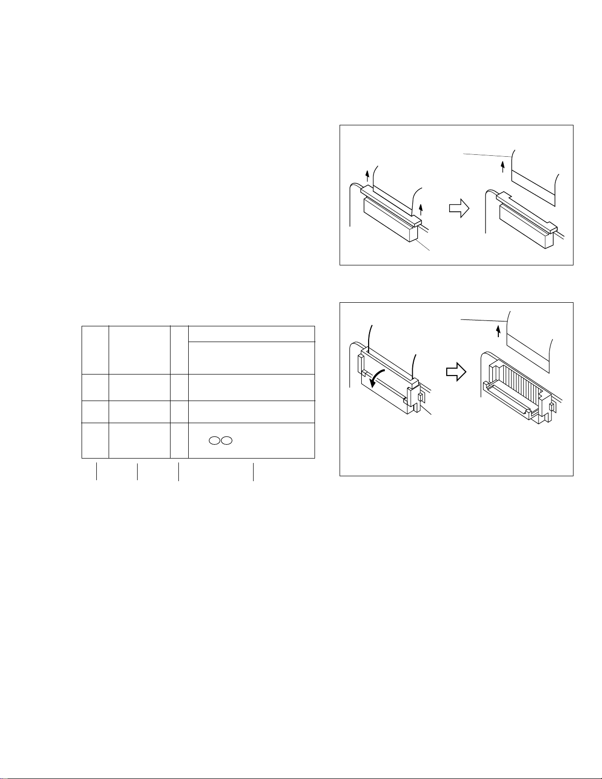
1.1.2 How to read the disassembly and assembly
(For Cabinet Parts)
STEP
/LOC PART
NO.
Fig.
No.
REMOVAL
*UNLOCK/RELEASE/
UNPLUG/UNCLAMP/
UNSOLDER
1 CASSETTE C1 2(S1)
COVER ASSEMBLY
1.1.3 Connection of the wires
1. Pull the connector structure upward to release the clamp
when removing or inserting the flat wire cable.
Wire
Connector
Fig. 1-1-1
Wire
2
UPPER CASE C2 2(S2), (L2)
LOWER CASE C3 9(S3), (L3a), (L3b)
3 ASSEMBLY(INCL. *CN 3a 3b
E. VF. ASSEMBLY) CAP (RCA jack)
▲▲
(1) (2) (3) (4)
(1) Order of steps in Procedure
When reassembling, preform the step(s) in the reverse
order. These numbers are also used as the identifica-
tion (location) No. of parts Figures.
(2) Part to be removed or installed.
(3) Fig. No. showing Procedure or Part Location.
C = Cabinet
CA = Camera
D = Deck
(4) Identification of part to be removed, unhooked, unlocked,
released, unplugged, unclamped or unsoldered.
P = Spring
W = Washer
S = Screw
* = Unhook, unlock, release, unplug or unsolder.
2(S3) = 2 Screws (S3)
CN = Connector
(5) Adjustment information for installation.
▲
▲
NOTE:
Connector
After removing the wire, return the stopper to
its original position, because it is apt to come
off if it is left open.
Fig. 1-1-2
1-1
Page 4
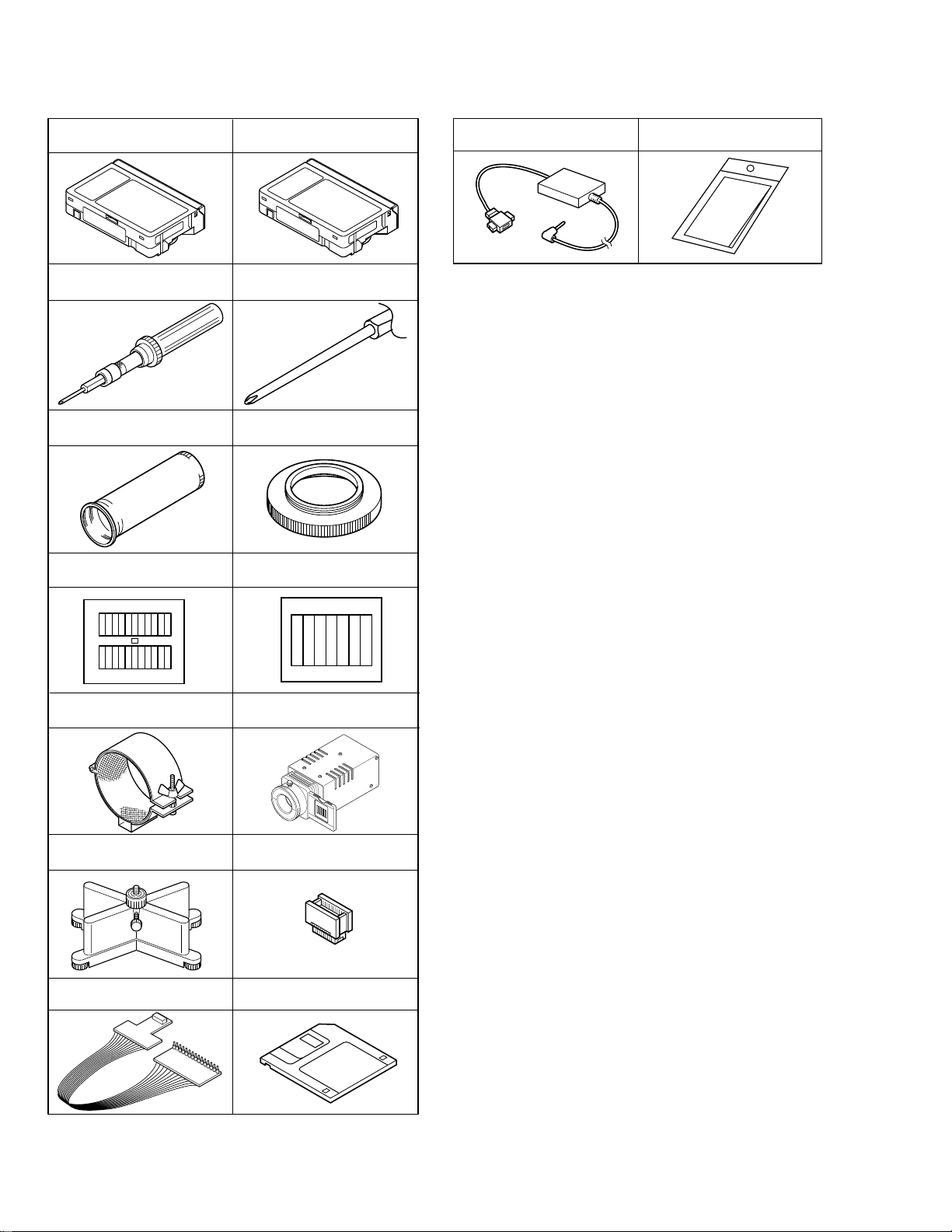
1.2 TOOLS REQUIRED FOR ADJUSTMENTS
Alignment tape
(for SP interchangeability)
1
3
5
78
MHP-C
Torque driver
YTU94088
INF adjustment lens
YTU92001B
Gray Scale Chart
YTU94133A
Alignment tape
(for N. SP PB Y/C level)
2
4
6
MHV-2C
YTU94088-003
Conn. ring
YTU92001-111
Color Bar Chart
YTU94133C
Bit
15 16
PC cable
QAM0099-002
Table 1-2-1
Cleaning cloth
KSMM-01
INF lens holder
910
11 12
13
YTU94087
Camera stand
YTU93079
Jig connector cable
YTU93106A
Light box Assembly
YTU93096A
Extension connector
YTU94145B-30
Service support system software
14
YTU94057-51
1-2
Page 5
1,2. Alignment tape
To be used for check and adjustment of interchangeability
of the mechanism.
(Video: Color bar signal, Audio: Non-signal)
3. Torque driver
Be sure to use to fastening the mechanism and exterior
parts because those parts must strictly be controlled for
tightening torque.
4. Bit
This bit is slightly longer than those set in conventional
torque drivers.
5. INF adjustment lens
To be used for adjustment of the camera system.
6. Conn. ring
The connector ring to attach the INF. lens to the head of
the OP lens.
7. Color bar chart
To be used for adjustment of the camera system.
8. Gray scale chart
To be used for adjustment of the camera system.
9. INF lens holder
To be used together with the camera stand (11) for
operating the VideoMovie in the stripped-down condition
such as the status without the exterior parts or for using
commodities that are not yet conformable to the
interchangeable ring.
10. Light box
To be used for adjustment of the camera system.
11. Camera stand
To be used together with the INF adjustment lens holder.
12. Extention connector
To be used to JIG connector cable
13. JIG connector cable
Connected to CN25 of the main board and used for
measuring error rates, etc.
14. Service support software
To be used for adjustment with a personal computer.
15. PC cable
To be used to connect the VideoMovie and a personal
computer with each other when a personal computer is
used for adjustment.
16. Cleaning cloth
Recommended cleaning cloth to wipe down the video
heads, mechanism (tape transport system), optical lens
surface.
1.3 DISASSEMBLY/ASSEMBLY OF CABINET PARTS
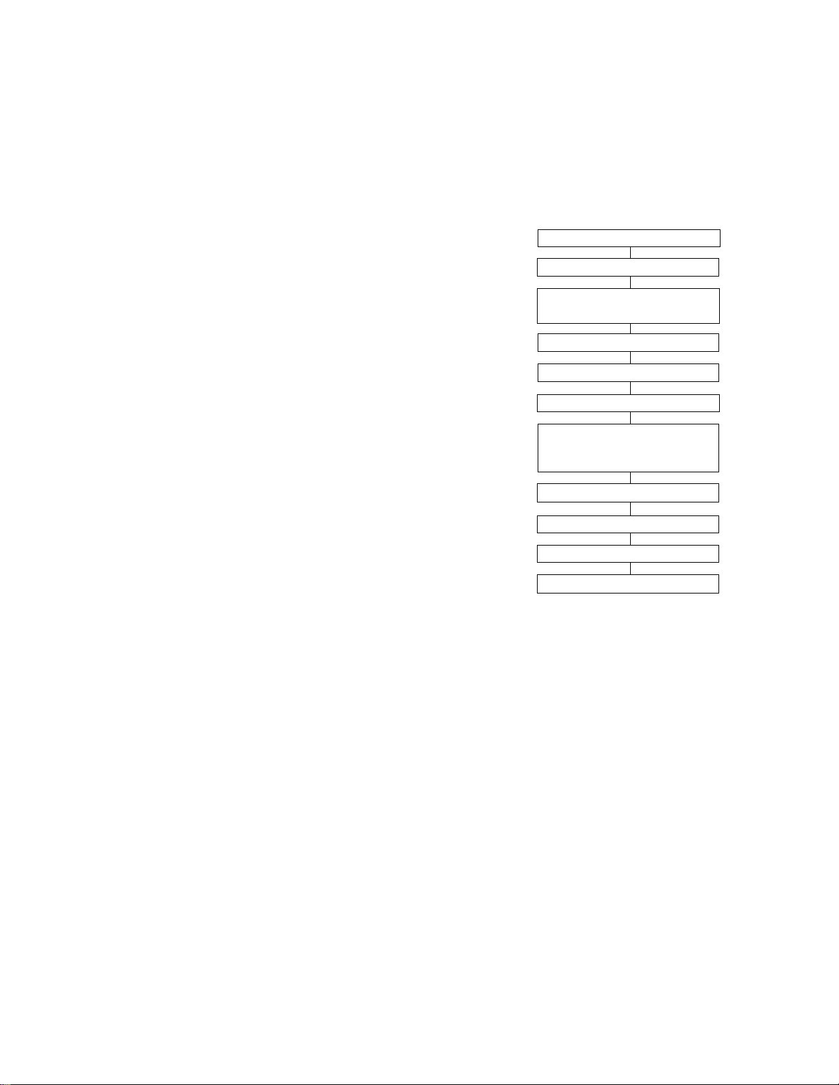
1.3.1 Disassembly flow chart
This flowchart indicates the disassembly step for the cabinet parts and board assembly in order to gain access to
item(s) to be serviced. When reassembling, perform the
step(s) in reverse order. Bend, route and dress the flat cables as they were originally.
1 Cassette cover assembly
2 Upper case
▼
▼
3 Lower case assembly
(Incl. E. VF assembly)
▼
4 E. VF assembly
▼
5 Top operation unit
6 Rear unit
▼
▼
7 Front cover assembly
(Incl. Microphone,
DC light assembly)
▼
8 Microphone
9 DC light assembly
▼
▼
▼
0 Monitor assembly
- Front frame assembly
▼
Note:
For screw management, refer to the table appearing
in the section "3.4 SERVICE NOTE" (page 3-6).
1-3
Page 6
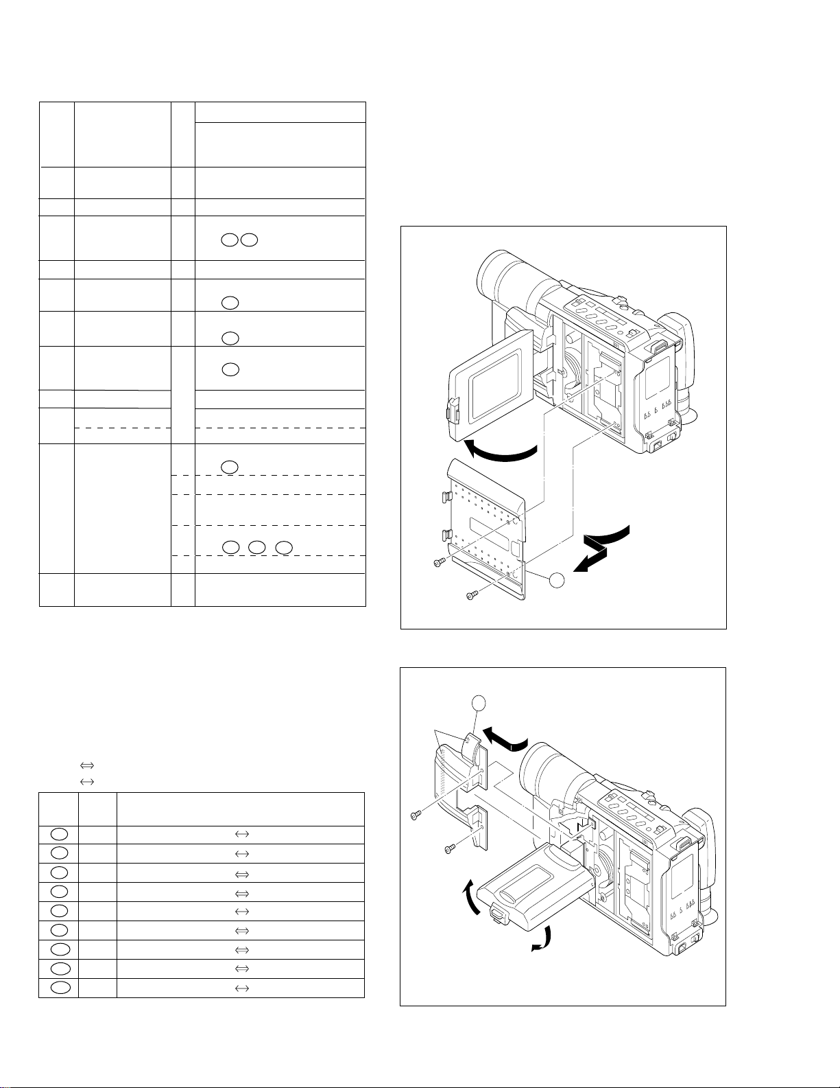
1.3.2 Disassembly method
2
(L2)
3
(S2)
4
(S2)
STEP
/LOC PART
NO.
1 CASSETTE C1 2(S1)
COVER ASSEMBLY
2
UPPER CASE C2 2(S2), (L2)
3 LOWER CASE C3 9(S3), (L3a), (L3b)
ASSEMBLY (INCL. *CN 3a 3b
E. VF ASSEMBLY) CAP (RCA jack)
4 E. VF ASSEMBLY C4 3(S4)
5 TOP OPERATION C5 2(S5), (L5a), (L5b), (L5c)
UNIT *CN 5a
6 REAR UNIT C6 3(S6), (L6a), (L6b)
7 FRONT COVER C7 2(S7a), (S7b), (L7a), (L7b)
ASSEMBLY (INCL. MIC *CN 7a
DC LIGHT ASSEMBLY)
8 MICROPHONE (S7a)
DC LIGHT ASSEMBLY 2(L7c)
9
COVER (LIGHT) 2(L7c)
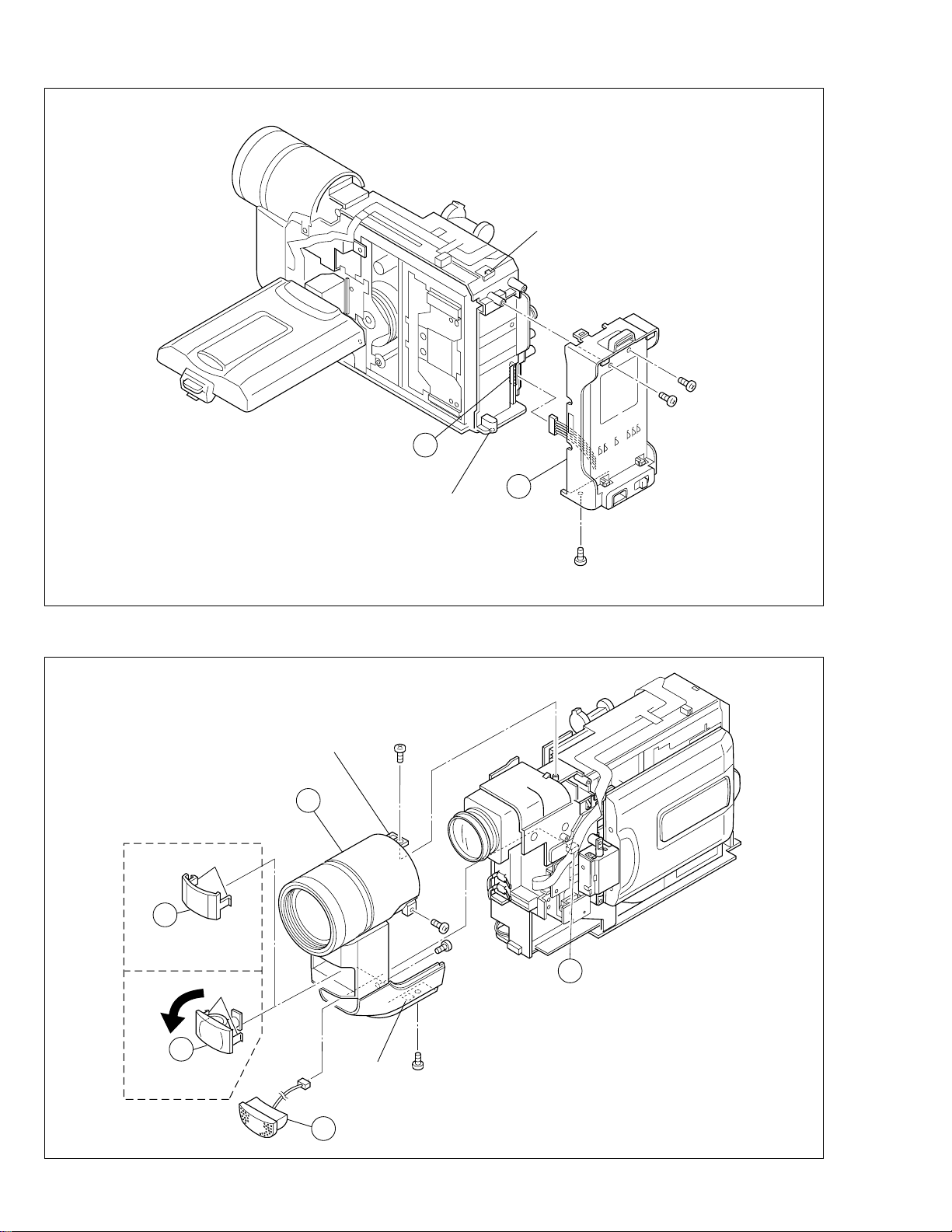
0 MONITOR ASSEMBLY C8 2(S8a), (S8b)
- FRONT FRAME C13 2(S13)
ASSEMBLY
List of Abbreviations:
2(S1)=2 screws (S1)
4(L1a)=4 Locking Tabs
CN=Connector
Reference Notes:
<NOTE 1>
Destination of connectors
Note:
Two kinds of double-arrows in connection tables
respectively show kinds of connector/wires.
: Flat wire
: Wire
Con- No. of
nector Pins
3a 2 SPEAKER MAIN CN27
3b 5 E. VF (B/W) MAIN CN12
5a 12 TOP OPERATION UNIT MAIN CN18
6a 13 REAR UNIT MAIN CN28
7a 2 MIC MAIN CN8
8a 33 MONITOR ASSEMBLY MAIN CN16
11a 28 MONITOR CN7501 T. HINGE
11b 24 MONITOR CN7502 LCD MODULE
11c 2 MONITOR CN7503 BACK LIGHT
REMOVAL
Fig.
No.
C9 2(S9a), (S9b), (S9c), (S9d)
C10 2(S10a), 2(S10b), 2(S10c),
C11 (L11a), (L11b), (L11c)
C12 2(S12a), (S12b), 2(L12a)
*UNLOCK/RELEASE/
UNPLUG/UNCLAMP/
UNSOLDER
*CN 6a
*CN 8a
(L10a), (L10b), (L10c)
*CN 11a , 11b , 11c
Connector
<NOTE 2, 3>
(1) The FPC assembly should be winded around the hinge
assembly by two and half turns so that the wire to be
connected to the monitor board assembly is positioned
inside.
(2) The upper and lower hinge covers should be mounted so
carefully the any wire is not caught into either of the
covers.
1
(S1)
2
(S1)
1
Fig. C1
1-4
Fig. C2
Page 7
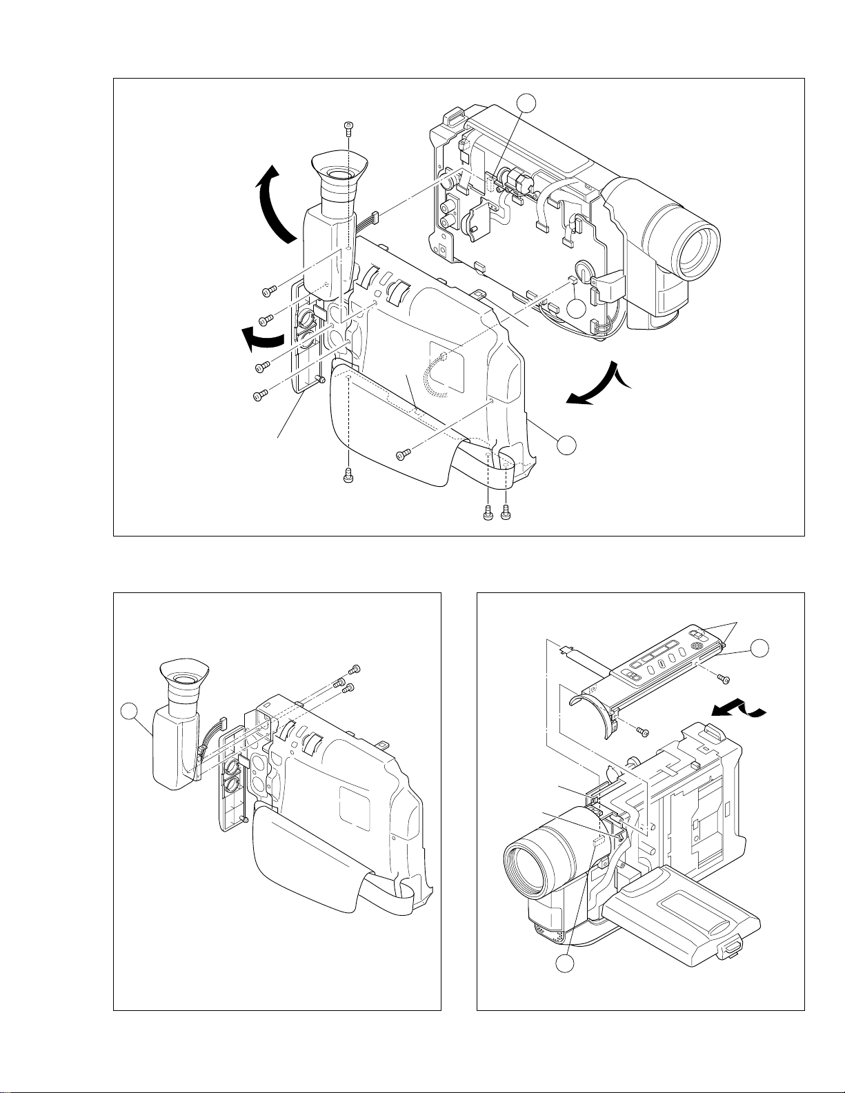
5
5a
18
(S5)
17
(S5)
(L5c)
(L5a)
(L5b)
8
(S3)
6
(S3)
7
(S3)
9
(S3)
CAP
(RCA jack)
13
(S3)
5
(S3)
(L3b)
10
(S3)
12
(S3)
3b
3a
(L3a)
3
11
(S3)
4
16
(S4)
Fig. C3
14
(S4)
15
(S4)
Fig. C4
Fig. C5
1-5
Page 8
6a
(L6a)
Fig. C6
(L6b)
20
(S6)
19
(S6)
6
21
(S6)
(L7c)
9
NO.VIDEO
LIGHT MODEL
(L7c)
9
VIDEO LIGHT
USED MODEL
(L7a)
7
8
(L7b)
22
(S7a)
23
(S7a)
(S7a)
24
(S7b)
25
7a
1-6
Fig. C7
Page 9
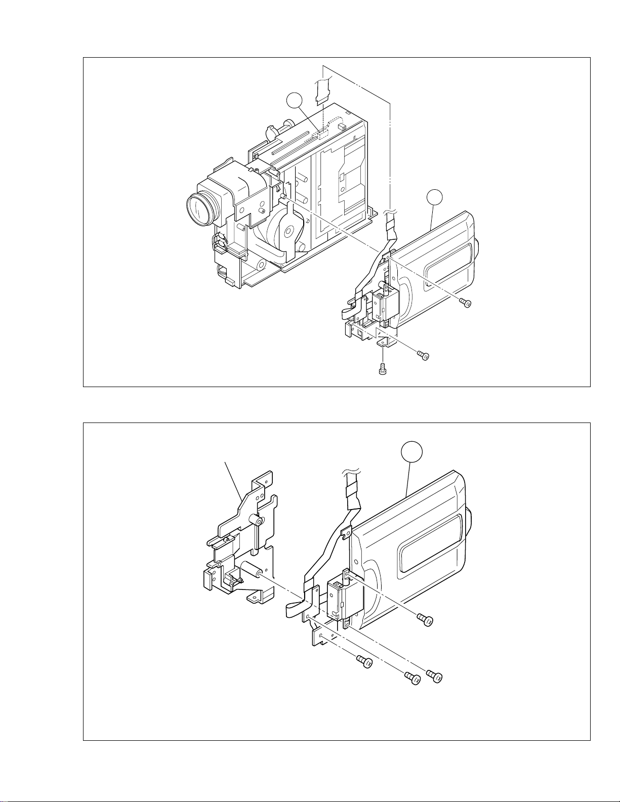
8a
10
26
(S8a)
Fig. C8
Bracket (Upper) ASSY
28
(S8b)
27
(S8a)
10
29
(S9a)
32
(S9c)
Fig. C9
31
(S9b)
30
(S9a)
1-7
Page 10
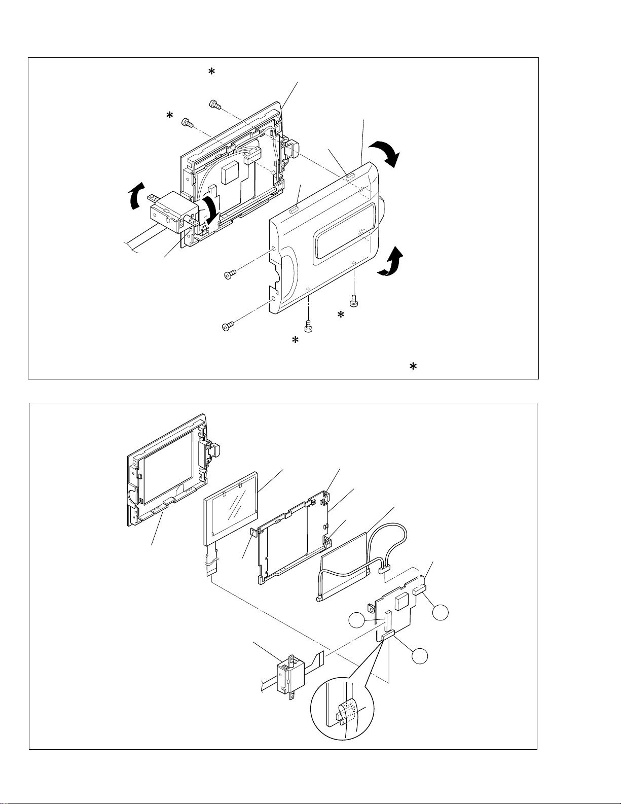
37
(S10c)
(L10c)
38
(S10c)
33
(S10a)
34
(S10a)
Upper case assy
Monitor cover
(L10a)
(L10b)
36
(S10b)
35
(S10b)
: 0.118 N·m (1.2 kgf·cm)
Monitor case
Fig. C10
LCD module
(L11a)
T.Hinge assy
(L11b)
Holder
(L11c)
11a
Back light
Monitor
<07>
11c
11b
1-8
Fig. C11
Page 11

Reinforced
(
)
surface
FPC
Cover (Hinge U)
39
(S12a)
Hinge
(L12a)
Cover (Hinge L)
40
(S12a)
Plate (SW)
41
S12b
Push switch
Reinforced
surface
Reinforced
surface
Hinge
Note 2,3
FPC
Fig. C12
42
(S13)
11
43
: 0.098 N·m (1.0 kgf·cm)
Fig. C13
(S13)
1-9
Page 12

1.4 DISASSEMBLY/ASSEMBLY OF CAMERA SECTION AND DECK SECTION
1.4.1 Flowchart of disassembly
The following flowchart shows the disassembly of the camera
section and deck section. When assembly of the camera
section and deck section, follow this flowchart in the reverse
order.
<Camera section/Deck section>
1
Zoom unit assembly
▼
2 Main board assembly
3 OP block assembly
▼
(Incl. CCD board assembly)
▼
3 OP block assembly
3
CCD board assembly
For details of disassembly of
manner, refer to page 1-12,
“1.5 REPLACEMENT OF
CCD IMAGE SENSOR.
▼
▼
4 Frame assembly
5 Cassette housing assembly
▼
Reference Notes:
<NOTE 1>
Open two pins of the cennter and connect CN4 as shown in
Fig.
<NOTE 2>
Destination of connectors
Two kinds of double-arrows in connection tables re-
Note:
spectively show kinds of connector/wires.
: Flat wire
: Wire
Con- No. of
nector Pins
Connector
1a 14 MAIN CN13 ZOOM UNIT
2a 14 MAIN CN2 SENSOR
2b 11 MAIN CN5 VIDEO/FLY. E HEAD
2c 10 MAIN CN1 DRUM MOTOR
2d 6 MAIN CN4 (PIN 1,2)
MAIN CN4 (PIN 5,6)
LOADING MOTOR
DC LIGHT
(OPEN TWO PINS OF
THE CENTER AND
CONNECT)
2e 22 MAIN CN15 OP BLOCK
2f 18 MAIN CN3 CAPSTAN MOTOR
2g 11 MAIN CN7 A/C HEAD
2h 14 MAIN CN22
CCD
1.4.2 Disassembly method
STEP
/LOC PART
NO.
Fig.
No.
*UNLOCK/RELEASE/
UNPLUG/UNCLAMP/
1 ZOOM UNIT D1 4(S1)
ASSEMBLY *CN 1a
2 MAIN BOARD D2 (S2), (L2a), (L2b)
*CN 2a , 2b , 2c , 2d , 2e
2f , 2g , 2h
3 OP BLOCK D3 2(S3)
ASSEMBLY CUSHION (OP)
4 FRAME ASSEMBLY D4 (S4a), 2(S4b), (S4c)
5 CASSETTE D5 4(S5)
HOUSING
ASSEMBLY
List of Abbreviations:
2(S1) = 2 Screws (S1)
4(L1a)=4 Locking Tabs (L1a)
CN=Connector
REMOVAL
UNSOLDER
1
(S1)
2
(S1)
4
(S1)
1
1a
3
(S1)
Fig. D1
1-10
Page 13

2
c
10
(S4b)
9
(S4b)
11
(S4c)
4
8
(S4a)
)
2h
(L2a)
3
2a
5
(S2)
2b
2c
2g
2e
2d
White
Fig. D2
2f
Note1
Red
Red
(L2b)
✽ : 0.108 N·m (1.1 kgf·cm)
Fig. D4
14
(S5)
5
12
(S5)
15
(S5)
13
(S5)
Cushion (OP
6
(S3)
Fig. D3
7
(S3)
Fig. D5
1-11
Page 14

1.5 REPLACEMENT OF CCD IMAGE SENSOR Notes:
•
Pay the most careful attention to the transparent glass
and optical LPF of the CCD image sensor so a not the
soil and damage them. If something is soiled with finger-prints, etc., gently clean it with silicon-processed
paper/cloth or chamois.
• When the CCD image sensor is shipped from the fac-
tory, there are protection seals applied onto the transparent glass. Leave the protector as it is, and take it off just
before assembling the CCD image sensor to the OP
block.
1.5.1 Removal of CCD image sensor
1. Remove two screws (1, 2) securing the CCD base assy,
and disassemble the CCD spacer, the optical LPF,
spacer rubber.
1.5.2 Installation of new CCD image sensor
1. Remove the protection seal from a new CCD image sensor. Next, put the optical LPF, spacer rubber, CCD spacer
on the CCD image sensor as they are piled up in this
order. At that time, make sure of orientation of each item
refering to the following table (see Fig. 1-5-1).
Part Name Orientation
CCD image sensor Mark is on the right viewed as indi-
cated by the arrow a .
Spacer rubber IC side is horizontal.
Optical LPF Marks are on the left and bottom
viewed as indicated by the arrow
a .
2. Fix the CCD base assy to OP block with the two screws
(1, 2) . At that time, be careful of the orientation.
3. After completion of all P.C. boards to the camera section, observe the monitor to confirm no vignetting caused
by the bodytube, rings, lens hood, etc. If no vignetting is
observed, it can be said that image's parallel, horizontality
and centering are correct.
1.5.3 Replacement of CCD board assy
1. Remove one screw (3).
2. Unsolder at the fourteen points on the CCD board assy.
1. Remove the screw (3) only when the CCD board
Note:
assy needs replacement.
2. When installing a new CCD board assy, carry out the
above-mentioned procedure in the reverse order.
Optical LPF
Blue
OP
side
CCD
side
(S1a)
CCD base assembly
CCD spacer
Spacer rubber
a
3
1
2
(S1a)
(S1b)
CCD board
assembly
1-12
Fig. 1-5-1
Page 15

1.6 TAKE OUT CASSETTE TAPE
In the event that the set enters the emergency mode as it is
loaded with a cassette tape and the cassette tape cannot
be ejected with the EJECT button, manually, take it out of
the set according to the following procedure.
Note:
If the mechanism comes into the unloading mode as
the cassette tape is not held by hand, it results in tape
damage.
1. Disconnect the set from the power source.
2. Remove the cassette cover assembly, Cover (VF), top
cover, (See Fig. C1, C2 and C3, Page 1-1, 2, 3 and 4)
3. Connect a jumper wire to each pole of the loading motor
as shown by the magnified view b (Fig. 1-6-1)
Battery
4. While holding down the cassette housing by hand, connect the jumper wires to a battery to run the mechanism
to the EJECT position four unloading. If this unloading
operation is performed as the cassette housing is not
held down by hand, the front lid of the cassette may
damage the tape when it is ejected.
5. For taking in the slack of the tape, run the mechanism
to the EJECT position as the front lid of the cassette is
left open, and turn the take-up gear in the forward direction to wind up the tape. After confirming that the tape
has completely been wound up and the supply reel is
idling, take the cassette tape out of the cassette housing.
Magnified view
Top view
b
Take-up gear
Fig. 1-6-1
1-13
Page 16

1.7 EMERGENCY DISPLAY
䊳
R
D
N
E
.
ECXZT
M
O
S
O
O
Y
D
M
SETEM ME
S
5
N
P
0
U
x
䊳
F
E
M
T
O
X
.
O
C
P
W
U
O
.
S
S
S
B
C
Y
U
.
A
S
R
M
T
E
EERMAMMEE
N
A
A
A
N
U
U
U
U
U
T
T
T
O
O
O
Whenever some abnormal signal is input to the
mechacon CPU, an error number (E01, as an exam-
• In an emergency mode, all operations except
turning on/off the POWER switch are ineffectual.
ple) is displayed in the electronic view finder.
In every error status, such the message as shown below alternately appear over and over.
Example (in case of the error number E01):
E01
UNIT IN
SAFEGUARD MODE
E01
REMOVE AND
REATTACH BATTERY
E. VF Symptom Mode when observed Resulting mode
E07 Short circuit of capstan MDA Power ON Power OFF
E06 CAPSTAN FG input absent EDIT Power OFF
E04 DRUM FF input absent DRUM rotation Power OFF
E03 SUPPLY REEL FG input absent REC, PLAY, SEARCH, FF
E02
Mode control motor rotates for more than 10
UNLOADING Power OFF
UNLOADING
[Power OFF
sec without shift to next mode.
E01
Mode control motor rotates for more than 10
LOADING Power OFF
sec without shift to next mode.
E00 Overtime the programming transaction REC, PLAY Power OFF
1.8 DEMONSTRATION MODE
This model has the DEMONSTRATION mode.
1) How to set the DEMONSTRATION mode.
The camera can be entered into the DEMONSTRATION mode by setting on the DISPLAY screen appearing in the viewfinder.
When entering the camera into the DEMONSTRA TION
mode, pay heed to the following matters.
1. Set the POWER switch to turn on
the "M".
Press the MENU WHEEL once. The
first page of the DISPLAY appears
on the LCD monitor (or in the
MENU Wheel
M
A
F
F
O
Y
A
L
P
Recording Start/Stop Button
viewfinder).
No cassette is set in the camcorder or a cassette is set
in the camcorder but it is protected from recording.
Note 1)
The indications of the DISPLAY page very
depending on the setting.
2) How to cancel the DEMONSTRATION mode.
To cancel the DEMONSTRATION mode, turn the
POWER switch off (“POWER OFF”).
2. Turn the MENU WHEEL in the
direction of the arrow to set the
cursor at “NEXT”.
Press the MENU WHEEL once.
The second page of the DISPLAY
appears on the LCD monitor (or in
the viewfinder).
E
T
N
S
Y
S
䊳
T
E
O
M
A
C
E
R
E
M
C
I
T
M
I
N
I
T
.
T
C
T
E
A
L
E
M
A
T
I
L
T
L
E
M
D
A
I
T
T
E
/
D
D
E
O
M
M
O
䊳
R
N
R
E
T
U
U
A
MMEEN
R
U
O
F
F
E
O
F
F
O
R
O
F
F
N
GM.
F
R
EFNCH
E
E
O
F
See to
next page
1-14
Fig. 1-8-1
Display 1
Display 2
Page 17

Refer to Fig. 1-9-2.
While the DEMONSTRATION
mode is activated, a word of
DEMONSTRATION is
appearing on the screen
scrolling from right to left.
DENO MODE
OFF
ON
EXIT
䊳
R
I
T
T
D
J
D
V
䊳
T
E
N
E
I
A
L
E
I
R
O
C
T
L
T
T
I
M
D
E
.
E
L
E
P
O
E
T
C
T
E
/
O
U
S
A
I
T
M
T
I
M
R
Y
M
M
I
A
L
I
D
O
O
N
S
E
E
M
C
A
M
D
U
T
R
E
R
N
E
N
E
T
E
A
O
G
O
M
.
.
M
MEE
N
O
O
O
F
0
O
S
N
U
F
F
F
R
6
N
E
U
F
F
F
ENACMH
Note 2)
As the “DEMO MODE” is executed, the
camcoder enters the DEMONSTRATION mode
after the title screen of “TITLE CALL” and
“FUTURE” appear in this order.
<Flow chart>
1. TITLE CALL and FUTURE
2. FOG
3. ND EFFECT
4. FADER/WIPE (BLACK)
5. MOSAIC
6. SHUTTER
7. SLIDE
8. DOOR
9. CORNER
10. WINDOW
11. NEGA/POSI
12. STRETCH
13. MOSAIC
14. SEPIA
15. B/W
16. STROBE
17. CLASSIC
18. VIDEO ECHO
35. PIN UP SNAPSHOP
34. WIDE ANGLE
33. 30 ~ 32 (For DSC MODEL ONLY)
32. D.S.C. 9 FRAME
31. D.S.C. 4 FLAME
30. D.S.C. INDEX
29. NIGHT ALIVE 10X
28. NIGHT ALIVE OFF
27. S-VHS (For S-VHS MODEL ONLY)
26. VHS
25. P. STABILIZER OFF
24. P. STABILIZER OFF
23. P. STABILIZER ON
22. P. STABILIZER OFF
21. WIDE OFF
19. WIDE OFF
3. Turn the MENU WHEEL in the
direction of the arrow to set the
cursor at “DEMO MODE”. Then,
press the MENU WHEEL once.
The third page of the DEMO
MODE appears on the LCD
monitor (or in the viewfinder).
20. WIDE ON
Fig. 1-8-2
4. Turn the MENU WHEEL in the direction of the arrow to set the cursor at
“ON”. Then, press the MENU WHEEL
once.
The fourth page of the DISPLAY
appears on the LCD monitor (or in the
viewfinder).
(“DEMO MODE” is switched “ON” from
“OFF” status.)
Display 4Display 3
5. Press the MENU WHEEL once.
The camcorder automatically
enters the DEMONSTRATION
mode and it repeats demonstration operation.
While the camcorder is performing demonstration, all operations
except turning on/off the POWER
switch are ineffectual.
1-15
Page 18

SECTION 2
MECHANISM ADJUSTMENT
2.1 SERVICE CAUTIONS
2.1.1 Precautions
1. Before disassembling/re-assembling the set as well as
soldering parts, make sure to disconnect the power
cable.
2. When disconnecting/connecting connectors, pay enough
attention to wiring not to damage it.
3. When installing parts, be careful not to do with other parts
as well as not to damage others. (Pay the most careful
attention to the upper drum assy and tape transport
mechanism.)
2.1.2 How to read the disassembly and assembly
(For Mechanism Parts)
(1) Order of steps in Procedure
When reassembling, perform the step(s) in the reverse
order. These numbers are also used as the identification (location) No. of parts Figures.
(2) Part to be removed or installed.
(3) Location of part.
T = Top
B = Bottom
(4) Fig. No. showing Procedure or Part Location.
M = Mechanism
(5) Identification of part to be removed, unhooked, un-
locked, released, unplugged, unclamped or unsoldered.
P = Spring
W = Washer
S = Screw
* = Unhook, unlock, release, unplug or unsolder.
2.1.3 Required adjustment tools
Alignment tape
MHPE-C
Jig connector cable
YTU93106A
Cassette torque meter
PUJ50431-2
Table 2-1-1
Alignment tape
MHPE-LC
Extension connector
YTU94145B-30
Roller Driver
PTU94002-2
(6) Adjustment information for installation.
(+) = Refer to Exploded Views for Lubrication information.
(For Mechanism Parts)
STEP/LOC.
No.
PART
Fig.
No.
REMOVAL INSTALLATION
*UNHOOK/UNLOCK ADJUSTMENT
/RELEASE/UNPLUG CONDITION
/UNSOLDER NOTE
1 ROLLER BASE ASSEMBLY T M1 (S1) –
2 TENSION ARM ASSEMBLY T M1 (P1), (W1a) –
3 REEL DISC (SUP) T M1 (W1a), (W1b) _
4 SLANT ARM ASSEMBLY T M1 (W1a) –
5 CANCEL LEVER ASSEMBLY T M2 (W2) _
6 EJECT LEVER ASSEMBLY T M2 (W2) –
7 CASSETTE GUIDE (L) ASSEMBLY T M2 (S2) –
5
(1) (2) (3) (4) (5) (6)
2-1
5
5
5
5
5
Page 19

2.2 DISASSEMBLY/ASSEMBLY OF MECHANISM PARTS
This procedure starts with the condition that the cabinet parts and deck parts. Also, all the following procedures for adjustment
and parts replacement should be performed in STOP mode. When reassembling, perform the step(s) in the reverse order.
REMOVAL INSTALLATION
*UNHOOK/UNLOCK ADJUSTMENT
/RELEASE/UNPLUG CONDITION
/UNSOLDER NOTE
STEP/LOC.
No.
PART
Fig.
No.
1 ROLLER BASE ASSEMBLY T M1 (S1) –
2 TENSION ARM ASSEMBLY T M1 (P1), (W1a) –
3 REEL DISC (SUP) T M1 (W1a), (W1b) –
4 SLANT ARM ASSEMBLY T M1 (W1a) –
5 CANCEL LEVER ASSEMBLY T M2 (W2) –
6 EJECT LEVER ASSEMBLY T M2 (W2) –
7 CASSETTE GUIDE (L) ASSEMBLY T M2 (S2) –
8 SUPPLY CLUTCH ASSEMBLY T M2 (W2) –
9 WHEEL GEAR T M2 (W2) See, Adjustment procedure for
Section 1.3
0 ROTARY ENCODER B M3 4(S3a)
The function of this part varies according to the assembly (YMA0030A-E/
YMA0031A-E) which this part is incorporated in.
! TIMING BELT B M3 ––
@ CENTER PULLEY UNIT T/B M3 2(S3a) –
# CASSETTE GUIDE (R) ASSEMBLY T M3 (S3b), (P3) (Only use YMA0031A-E)
$ TU GEAR T M3 (W3a) –
% BRAKE SUB GEAR T M3 (W3a) –
^ P.R ARM ASSEMBLY T M3 (W3b) –
& TU GUIDE ARM ASSEMBLY T M3 (W3b) –
* LINK ARM ASSEMBLY T M4 (W4) –
( LED GUIDE T M4 (S4a) –
) A/C HEAD UNIT T M4 2(S4b) –
q SLANT POLE BASE ASSEMBLY T M5 (S5a) –
w CAP MOTOR ASSEMBLY T M5 3(S5a) –
e MOTOR BASE T M5 2(S5b), (S5c) –
r BRUSH B M6 (S6a) –
t DRUM FINAL T/B M6
2(S6b), 2(S6c) *CATCHER
–
y GUIDE RAIL T M6 8(S6d) –
u POLE BASE (SUP) T M6 ––
i POLE BASE (TU) T M6 ––
o COVER PLATE T M7 ––
p DRIVE LEVER ASSEMBLY T M7 ––
Q MOTOR BRACKET ASSEMBLY T M7 3(S7) –
W CONTROL CAM T M8 (W8a) See, Adjustment procedure for
Section 1.3
E LINK LEVER T M8 ––
R MIDDLE GEAR T M8 ––
T LOADING GEAR(T) ASSEMBLY T M8 (W8b) See, Adjustment procedure for
Section 1.3
Y LOADING GEAR(S) ASSEMBLY T M8 (W8b) –
U LOADING RING ASSEMBLY T M8 4(S8) See, Adjustment procedure for
Section 1.3
Table 2-2-1
2-2
Page 20

<TOP VIEW>
31
37
25
26
<BOTTOM VIEW>
1
29
28
27
4
36
2
5
9
3
34
Fig. 2-2-1 TOP VIEW
20
21
19
22
23
17
16
14
15
18
12
33326830357
13
Note:
When reinstalling the cassette housing to
the set, pay careful attention to the switch
not to damage it.
2-3
24
11
10
Fig. 2-2-2 BOTTOM VIEW
Page 21

2
16
12
17
14
11
(W3a)
15
(W3a)
(W3a)
(W3b)
(S3a)
(S3b)
(P3)
(S3a)
(S3a)
(S3a)
(S3a)
10
13
(W1a)
(S1)
1
(W1a)
(P1)
(W1a)
3
4
(W1b)
Fig. M1 Fig. M3
5
(W2)
9
(S2)
(W2)
6
(W2)
7
8
18
(S4a)
(W4)
19
(S4b)
20
(S4b)
Fig. M4Fig. M2
2-4
Page 22

22
(S5a)
(S5a)
21
(S5a)
31
(S7)
27
(S5b)
Catcher
28
(S6b)
Fig. M5
(S6d)
25
(S5c)
23
(S8)
29
30
Fig. M7
(S8)
37
2-5
(S6d)
(S6c)
(S6c)
Fig. M6
(S6d)
26
24
(S6a)
(S6d)
36
(W8a)
32
(W8b)
(W8b)
35
33
34
Fig. M8
Page 23

2.3 CHECKUP AND ADJUSTMENT OF MECHANISM PHASE
Note:
Pay careful attention to the installing order and
phase of mechanism parts of the loading system.
Align the hole of the Loading gear
(T) assembly to that of the deck.
Align the two holes of the Loading
ring assembly to those of the deck.
Align the hole of the
link lever assembly to
the deck hole.
Align one of the three holes of
wheel gear to the deck hole.
lign this part to each
Triangle" mark.
Align each one link lever
assembly hole and deck
hole to the hole at the
control cam position.
Fig. 2-3-1 Top of main deck
Align this part to each
"Triangle" mark.
Fig. 2-3-2 Rotary encoder
2-6
Page 24

2.4 TAPE TRANSPORT ADJUSTMENT
In most cases the deck section is in need electrical adjustment, it results from replacement of worm mechanical parts
or video heads. In the event of malfunction with electrical
circuits, troubleshouting with the aid of proper test instruments most be done first, and then commence necessary
repair, replacement and adjustment, etc.
2.4.1 Back tension
1. Set a cassette torque meter onto the deck and measure
the back tension in standard REC mode to confirm that
the back tension is 7 – 14 gf
•cm.
2. If not, replace the tension band.
When the value widely fluctuates in the measurement,
replace the supply reel disk.
3. With the cassette torque meter, confirm that the play
torque is 15 – 25 gf
•cm.
If necessary, replace the center pully unit.
8. When the FM waveform breaks in the level varying process, subtly adjust the height of guide rollers at every
breaking point so that the waveform varies as flat as possible.
Repeat the above steps 6. and 7. several times to confirm that the waveform is flat as a whole.
9. Playback the LP stairstep signal of alighment tape and
adjust the tracking control to maximize the FM waveform, confirm that FM waveform variation is always
flat.
10. Record the signal and play it back in both of the SP and
LP modes, and confirm that the FM waveform is flat in
both modes.
Note:
Among the above-mentioned adjustment steps,
the items of No. 9 and No. 10 are needed for the
LP model only.
CH-2
1 field
Back tension
-3
0.7x10
(7-14gf·cm)
-1.37x10⁻³ N•cm
Play torque
1.47x10
-3
-2.45x10⁻³ N·m
(15-25gf·cm)
Fig. 2-4-1 Cassette torque meter
2.4.2 Tape pattern
1. Remove the Cover (JIG) shwon on Fig. 2-6-1 (Page 2-10).
2. Connect the jig connector cable to CN25 on the MAIN
board as shwon on Fig. 2-6-1 (Page 2-10).
3. Observe signal at V. TP FM with external trigger from V.
FF on the jig connector cable.
4. Playback the SP stairstep signal of the alignment tape
and maximize the FM waveform by the tracking button.
5. Set the tracking control to the center position by simultaneously pressing the tracking (-) and (+) buttons and
maximize the FM waveform by the tracking button.
6. If the observed FM waveform is not flat, adjust the height
of the supply of take-up guide roller with the roller driver.
Causer by wrong height
of supply guide roller
Flatten waveform.
Caused by wrong height
of take-up guide roller
Fig. 2-4-2 FM waveform-1
Correct variation of waveform
Bad variation of waveform
Fig. 2-4-3 FM waveform-2
To prevent the tape from damage, turn the guide
Note:
rollers slowly.
7. By operating the tracking button (both in + and – directions) in the manual tracking mode, vary the output level
of the FM waveform from maximum to minimum and
vice versa to confirm that the waveform varies nearly in
a flat shape.
2-7
Page 25

11. Through the above steps, confirm that there occur no
A/C head
Screw C
Screw B
Screw A
g
wrinkling and damage in the tape around the pinch roller
and TU guide pole whenever the deck is in operation of
Loading/Unloading, Search Rewind and at mode change
from Search Rewind to play mode. If wrinkling or damage in the tape occurs around the TU guide pole, adjust
the angle (slant) of the A/C head to the tape. So that the
tape normally runs along the lower flange of the guide
pole.
Pole base (SUP)
(Guide roller)
Pole base (TU)
(Guide roller)
TU guide
pole
2.4.3 A/CTL head height & azimuth
1. Connect the jig connector cable to CN25 on the MAIN
board.
2. Connect the channel-1 scope probe to the audio output
and connect the channel-2 scope probe to PB CTL.
3. Playback the alignment tape.
4. Set the tracking to its center range by pressing the (+)
and (–) tracking controls simultaneously.
5. Adjust screws A , B and C approximately 45 degrees
in the same direction to obtain maximum audio output
and CTL signal levels.
6. As a final fine adjustment, adjust screw B for minimum
signal level fluctuation and screw C for maximum output signal level.
Tension
pole
Fig. 2-4-4 Tape transport system
Pinch
roller
Fig. 2-4-5 A/C head
Audio
signal
Control
pulse
si
nal
Fig. 2-4-6 Audio and CTL signal
2-8
Page 26

2.4.4 Phase of control head (X value)
1. Connect the jig connector cable to CN25 on the MAIN
board.
2. Playback the SP stairstep signal of the alignment tape
and observe signal at V.TP FM with external trigger from
V.FF on the jig connector cable.
3. Operate the tracking button in the center and manual
tracking mode by pressing the tracking (+) and (–) buttons and confirm that the FM output level is maximum
at the center position as shown in Fig. 2-4-8.
4. If necessary, slightly loosen the setscrews D and E and
insert the Tweezers into the notch and guide hole to
move the A/C head fully in the direction of the capstan
to the extent.
5. Gradually move the A/C head toward the drum to find
the position where the FM output level maximum for the
first time (a' – b' in Fig. 2-4-8).
6. Fine adjust the phase of the A/C head and tighten the
screws D and E at the point a.
A/C head
Insert the
Tweezers
2.5 REMARKS
2.5.1 Cleaning
1. For cleaning of the upper drum (particularly video heads),
use fine-woven cotton cloth or Kimwipe with alcohol
soaks through. Do not move the cloth but turn the upper
drum counterclockwise.
Make sure not to move the cloth in the vertical
Note:
direction to the video head, since it may cause
damage of the video heads.
2. For cleaning of parts of the tape transport system except
the upper drum, use fine-woven cotton cloth or cotton
swab soaked alcohol.
3. After cleaning, confirm that the cleaned parts are completely dry before loading the deck with cassette tape.
2.5.2 Applying oil and grease
1. Periodical oiling and greasing are not required but should
be done to new parts when replacing. If oil and grease
on the other parts of the other party are old and dirty,
wipe them clean and apply new oil or grease.
2. For parts and points to apply oil and grease, refer to the
exploded view of the mechanism assembly (M3).
Table 1-5-1 specifies oil and grease to be used.
3. When oiling, clean the objective parts with alcohol first
and apply one or two drop(s) of oil. Too much oiling
causes rotary parts to slip because of oil leakage.
Screw D
Screw E
Fig. 2-4-7 Phase of control head
a
FM output
Direction of capstan
Adjusting
point
A/C head phase
b
Direction of drum
Fig. 2-4-8 Phase adjustment point of control head
Max
Classification Name Symbol in drawing
Grease KYODO-SH-P AA
Oil YTU94027 BB
Table 2-5-1 Specific oil and grease to be used
2.5.3 Checkup
After replacement of the supply reel disk and tension band,
make sure to inspect back tension according to the adjustment procedure of MECHANISM ADJUSTMENT section.
Zero
2-9
Page 27

2.6 JIG CONNECTOR CABLE CONNECTION
Remove the cover (JIG).
Jig connector cable
Extention connector
Fig. 2-6-1 Jig connector cable connection
CN25
Cover(JIG)
MAIN BOARD CN25 Jig BOARD
MON_B
CVF_B
MON_G
CVF_G
MON_R
CVF_R
VF_PRO
VPP_7.8
MON_HD
DISCHG_L
MCU_RST
V_TP_FM
V_OUT
V_OVL
AO_SIG_J
PB_CTL
AL_J3.2V
JIG_TX
EJECT_SW
GND
I_MTR
GND
GND
GND
TXD
V_FF
RXD
NC
NC
NC
1
16
2
17
3
18
4
19
5
20
6
21
7
22
8
23
9
24
10
25
11
26
12
27
13
28
14
29
15
30
16
17
18
19
20
21
22
23
24
25
26
27
28
29
30
1
MON_B
CVF_B
2
MON_G
CVF_G
3
MON_R
CVF_R
4
GND
I_MTR
5
GND
VF_PRO
6
GND
VPP_7.8
7
MON_HD
DISCHG_L
8
GND
MCU_RST
9
TXD
V_FF
10
RXD
V_TP_FM
11
V_OUT
V_OVL
12
AO_SIG_J
PB_CTL
13
AL_J3.2V
JIG_TX
14
EJECT_SW
NC
15
NC
NC
Fig. 2-6-2 Jig connector cable schematic diagram
2-10
Page 28

SECTION 3
p
ELECTRICAL ADJUSTMENT
3.1 ELECTRICAL ADJUSTMENT
3.1.1 PREPARATION
1. Precaution
This model does not contain adjustment controls (VR).
General deck system, camera system and monitor system
adjustment are not required. However, if MAIN board and
MONITOR board need replacement, please use original
2
E
PROM on to new board. Then adjustment are not required.
And if parts such as the following need replacement, special
computerized adjustment are required (Refer to sec. 3.1.1-
4). Please contact to JVC Service for detaile information.
• OP block
2
• E
PROM (IC104 of MAIN board)
• MONITOR
In the event of malfunction with electrical circuits, troubleshooting with the aid of proper test instruments most be
done first, and then commence necessary repair, replacement and adjustment, etc.
1. In case of wiring to chip test points for measurement, use
IC clips, etc. to avoid any stress.
2. Since connectors are fragile, carefully handle them in
disconnecting and connecting.
3. Shortcircuit between operation un it and DECK chassis.
2. Required test equipment
1. Color TV monitor.
2. AC power adapter
3. Oscilloscope (dual-trace type, observable 100 MHz or
higher frequency)
* It is recommended to use one observable 300 MHz or
higher frequency.
4. Digital voltmeter
5. Frequency counter (with threshold level adjuster)
6. Personal computer
3. Required adjustment tools
For detsails of special jigs necessary for adjustment, refer to
page 1-2 and 1-3 of the Section 1.
4. Setup for E. VF section adjustment
Referring to “SEC. 1 DISASSEMBLY” and connect the E.VF
WIRE to CN12 of the MAIN board.
(LY20686)
Bottom case assy
Parts No.
LY20686
Adjustment ltem : 3.3
Note:
•
This adjustmentalls into a special adjustment that requires
a personal computer.
For details, refer to “3.1.1 Preparation”.
Serial No.
label
Screw
5. Connection for Service support system
Fig. 3-1-1 Connection for Service support system
3-1
PC CABLE
RS232C
COM Port
Service Support
System software
MENU
Personal Com
uter
Page 29

7 FUSE LOCATION FOR MAIN BOARD ASSEMBLY
60
61
41
IC1601
80
120
17
IC2001
IC2401
4
85
IC4251
1
85
14
38 20
IC4501
119
IC105
9
8
16
1
IC107
5
4
8
1
24
13
FOIL SIDE
14
IC7005
CN12
14
8
5
F6002
F6003
0 1 MAIN PWB
YB10310-01-01
5
4
8
1
IC7006
CN28
113
13
24
2536
IC5202
40
21
157
148
37
IC5201
48
112
2536
112
37
48
24
13
105156
104
37
48
IC7001
1
2536
12
IC4001
208
152
43
IC106
IC104
1
5
8
4
4
2
3
1
56
53
2942
28
IC3501
15
114
0 1 MAIN PWB
YB10310-01-01
CN16
25
36
IC4702
95
17
IC6001
32
33
F6001
Fig. 3-1-2 FUSE location for MAIN board assembly (FOIL SIDE)
COMPONENT SIDE
8
13
24
37
14
116
48
1
29
114
CN2
IC7002
48
64
49
CN25
9
12
1
2
30
CN11
1
16
1
20
IC7008
IC7009
85
14
110
146
CN13
114
IC3003
3
4
5
IC3001
1
73
1
72
19
39
37
36
1
5
1
3
4
IC3002
IC102
1
5
3
4
111
176
1
44
109
1
12
CN19
CN18
IC4002
45
CN22
115
1
38
20
38
2
20 11
110
IC101
1
10
CN1CN5
11
IC4003
CN7
CN3
18 1
1
17
IC4202
148
IC4201
4
85
1
22
133
132
89
88
CN15
1
CN4
16
Fig. 3-1-3 FUSE location for MAIN board assembly (COMPONENT SIDE)
3-2
Page 30

7 FUSE LOCATION FOR MONITOR BOARD ASSEMBLY
COMPONENT SIDE
1
CN7502
28 1
24
R7516
0 7 MONITOR PWB
YB20900-01-01
CN7501
F7501
IC7501
14
85
21
CN7503
Fig. 3-1-4 FUSE location for MAIN board assembly (COMPONENT SIDE)
3.2 MONITOR ADJUSTMENT
Notes:
Unless otherwise specified, all measurement points
and adjustment parts are located on MONITOR board.
COMPONENT SIDE (A)
1
CN7502
CN7501
28 1
24
R7516
V COM
0 7 MONITOR PWB
YB20900-01-01
F7501
IC7501
14
85
21
CN7503
3.2.1 V COM
Signal •Alignment tape
•Stairstep
Mode •PB
Equipment • LCD MONITOR
Measurement point •–
Adjusting part • R7516 (V COM)
Specification • Black level must correctly be
reproduced on the LCD MONITOR.
(There is a sharp contrast
between black and white parts.)
(1) Adjust R7516 to make sharp contrast between black and
white parts on the LCD MONITOR screen.
(2) Adjust R7516 so that black and white levels (patticularly
black level in the contour) is sharply reproduced on the
LCD MONITOR screen.
3-3
Page 31

3.3 ELECTRONIC VIEWFINDER (E. VF) ADJUSTMENT
Notes:
Unless otherwise specified, all measurement points
and adjustment parts are located on E. VF board.
CRT
CENTERING
MAGNET
FOCUS
MAGNET
F.B.T
Fig. 3-3-1 E. VF
CRT-CN
VR4
BRIGHT
VR1
V. SIZE
50E. VF PWB ASSY
VR2
H. HOLD
CN2
CN1
(a)
Fig. 3-3-3 Horizontal sync. 1
(b)
Fig. 3-3-4 Horizontal sync. 2
3.3.2 PLL adjustment
Subject •Camera picture
Fig. 3-3-2 E. VF board
3.3.1 Horizontal sync.
Subject • Alignment tape
• Stairstep
Mode • PB
Equipment • E. VF
Measurement point • E. VF screen
Adjusting part • VR2 (H. HOLD)
Specification • The midpoint of the two
markings
1) Observing the viewfinder screen, turn VR2 fully clockwise
to make the picture unstable.
2) Slowly return VR2 counterclockwise to find a point where
the picture becomes stable, and mark this position.
3) Turn VR2 fully counterclockwise to make the picture
unstable in the same manner as 1) above.
4) Slowly return VR2 clockwise until the picture becomes
stable, and mark this position.
5) Finally set VR2 to the midpoint between the two markings
of 2) and 4).
Mode • EE
Equipment •E. VF
Measurement point • E. VF screen
Adjusting part •VR1 (V. SIZE)
Specification • Normal picture amplitude
1) Observing the viewfinder screen, adjust VR1 for normal
picture amplitude.
3.3.3 Centering
Subject •Alignment tape
•Stairstep
Mode • PB
Equipment •E. VF
Measurement point • E. VF screen
Adjusting part •Centering magnet (CRT assy)
Specification • The center of the E. VF screen
1) While observing the viewfinder screen, adjust the centering
magnet to locate the stairstep in the center of the viewfinder screen.
3-4
Page 32

3.3.4 Focus
Subject • Camera picture
Mode •EE
Equipment •E. VF
Measurment point •E. VF screen
Adjustment part •Focus magnet (CRT assy)
Specification •
1) While observing the viewfinder screen, adjust the focus
magnet for the deflecting yoke so that the picture at the
central area of the screen is clear and defined.
3.3.5 Brightness
Subject • -
Mode • EE
Equipment • E. VF
Measurment point • E. VF screen
Adjustment part • VR4 (BRIGHT)
Specification •
1) Close the lens with the cap and adjust VR4 so that the
raster of the CRT is just visible in the E. VF.
The center area is clear and defined
• Lens closed
The CRT raster is just barely visible
3-5
Page 33

3.4 SERVICE NOTE
3-6
 Loading...