

Page 1
SERVICE MANUAL
DIGITAL VIDEO CAMERA
GR-DX75US, GR-DX95US
For disassembling and assembling of MECHANISM ASSEMBLY, refer to the SERVICE MANUAL No.86700(MECHANISM ASSEMBLY).
SPECIFICATIONS
Camcorder
General
Power supply :
Power consumption
LCD monitor off,
viewfinder on : Approx. 3.4 W
LCD monitor on,
viewfinder off : Approx. 4.6 W
Dimensions
(W x H x D) : 55 mm x 102 mm x 96 mm (2-1/4"
Weight : Approx. 440 g (0.97lbs) (without
Operating
temperature :0°C to 40°C (32°F to 104°F)
Operating
humidity : 35% to 80%
Storage
temperature : –20°C to 50°C (–4°F to 122°F)
Pickup : 1/4" CCD (GR-DX300)
Lens : F 1.8, f = 3.8 mm to 38 mm (0.15"
Filter diameter : ø30.5 mm (1.2")
LCD monitor : 3" diagonally measured, LCD
Viewfinder : Electronic viewfinder with 0.24"
Speaker : Monaural
DC 11.0 V (Using AC Adapter)
DC 7.2 V
x 4-1/16" x 3-13/16")
(with the LCD monitor closed and
the viewfinder pushed back in)
grip belt) (GR-DX300)
Approx. 450 g (1lbs) (without grip
belt) (GR-DX95/DX75)
1/6" CCD (GR-DX95/DX75)
to 1.5"),
10:1 power zoom lens
(GR-DX300)
F1.6, f =2.7 mm to 43.2 mm (0.11"
to 1.7"),
16:1 power zoom lens
(GR-DX95/DX75)
panel/TFT active matrix system
(GR-DX300/DX95)
2.5" diagonally measured, LCD
panel/TFT active matrix system
(GR-DX75)
black/white LCD
(The specifications shown pertain specifically to the model GR-DX75US, GR-DX95US and GR-DX300US.)
(Using battery pack)
Digital Video Camera
Format : DV format (SD mode)
Signal format : NTSC standard
Recording/
Playback format : Video:
Cassette : Mini DV cassette
Tape speed : SP : 18.8 mm/s
Maximum
recording time : SP : 80 min.
(using 80 min. LP : 120 min.
cassette)
Digital Still Camera Function
Storage media : SD Memory Card/MultiMediaCard
Compression
system : Still image : JPEG
File size : 4 modes (1600 x 1200 pixels*,
Picture quality : 2 modes (FINE/STANDARD)
Approximate
number of
storable images :
* GR-DX300 only.
Specifications shown are for SP mode unless otherwise indicated. E & O.E. Design and specifications subject
to change without notice.
Digital component recording
: Audio: PCM digital recording,
32 kHz 4-channel (12-bit),
48 kHz 2-channel (16-bit)
LP : 12.5 mm/s
Moving image : MPEG4
1280 x 960 pixels*,
1024 x 768 pixels,
640 x 480 pixels)
(compatible)
(compatible)
Z pg. 18.
Connectors
S/AV
S-Video output : Y : 1 V (p-p), 75 Ω, analog
S-Video input : Y : 0.8 V (p-p) – 1.2 V (p-p), 75 Ω,
Video output : 1 V (p-p), 75 Ω, analog
Video input : 0.8 V (p-p) – 1.2 V (p-p), 75 Ω,
Audio output : 300 mV (rms), 1 kΩ, analog,
Audio input : 300 mV (rms), 50 kΩ, analog,
Edit : ø3.5 mm (0.14"), 2-pole
DV
Output : 4-pin, IEEE 1394 compliant
Input : 4-pin, IEEE 1394 compliant
USB : 5-pin
Power requirement
U.S.A and Canada : AC 120 V`, 60 Hz
Other countries :
Output : DC 11 V , 1 A
C : 0.29 V (p-p), 75 Ω, analog
analog
C : 0.2 V (p-p) – 0.4 V (p-p), 75 Ω,
analog
analog
stereo
stereo
AC Adapter
AC 110 V to 240 V`, 50 Hz/60 Hz
COPYRIGHT © 2003 VICTOR COMPANY OF JAPAN, LTD
GR-DX75US M3D327
GR-DX95US M3D337
No.86757
2003/06
Page 2
CONTENTS
Important Safety Precautions
1. DISASSEMBLY............................................................................................................................................................... 1-1
3. ADJUSTMENT................................................................................................................................................................ 3-1
4. CHARTS AND DIAGRAMS ............................................................................................................................................ 4-1
5. PARTS LIST.................................................................................................................................................................... 5-1
DIFFERENT LIST
DIFFERENT TABLE OF FEATURE
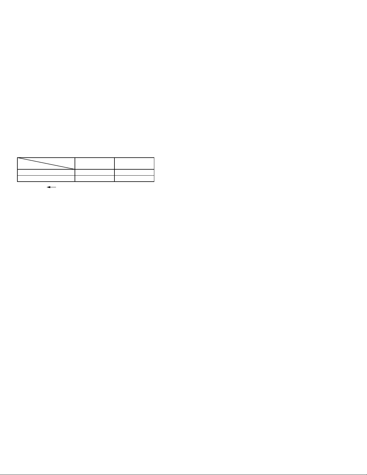
The following table indicate main different points between models GR-DX75US and GR-DX95US.
ITEM
LCD MONITOR 2.5 INCH 3.0 INCH
MEMORY CARD OPTIONAL
Notes: Mark is same as left.
MODEL
GR-DX75US
GR-DX95US
PROVIDED(MMC 8MB)
Page 3
Important Safety Precautions
Connector
Metal sleeve
Prior to shipment from the factory, JVC products are strictly inspected to conform with the recognized product safety and electrical codes
of the countries in which they are to be sold. However, in order to maintain such compliance, it is equally important to implement the
following precautions when a set is being serviced.
v
Precautions during Servicing
1. Locations requiring special caution are denoted by labels and
inscriptions on the cabinet, chassis and certain parts of the
product. When performing service, be sure to read and comply with these and other cautionary notices appearing in the
operation and service manuals.
2. Parts identified by the symbol and shaded ( ) parts are
critical for safety.
Replace only with specified part numbers.
Note: Parts in this category also include those specified to com-
ply with X-ray emission standards for products using
cathode ray tubes and those specified for compliance
with various regulations regarding spurious radiation
emission.
3. Fuse replacement caution notice.
Caution for continued protection against fire hazard.
Replace only with same type and rated fuse(s) as specified.
4. Use specified internal wiring. Note especially:
1) Wires covered with PVC tubing
2) Double insulated wires
3) High voltage leads
5. Use specified insulating materials for hazardous live parts.
Note especially:
1) Insulation Tape 3) Spacers 5) Barrier
2) PVC tubing 4) Insulation sheets for transistors
6. When replacing AC primary side components (transformers,
power cords, noise blocking capacitors, etc.) wrap ends of
wires securely about the terminals before soldering.
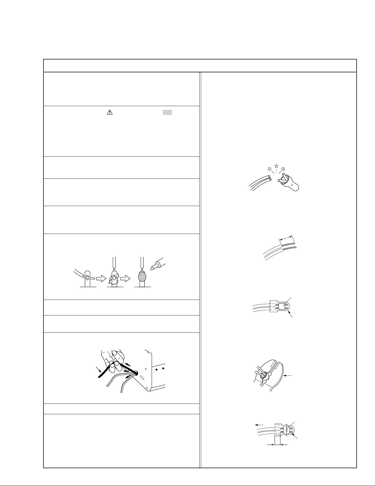
12. Crimp type wire connector
In such cases as when replacing the power transformer in sets
where the connections between the power cord and power
transformer primary lead wires are performed using crimp type
connectors, if replacing the connectors is unavoidable, in order to prevent safety hazards, perform carefully and precisely
according to the following steps.
1) Connector part number : E03830-001
2) Required tool : Connector crimping tool of the proper type
which will not damage insulated parts.
3) Replacement procedure
(1) Remove the old connector by cutting the wires at a point
close to the connector.
Important : Do not reuse a connector (discard it).
cut close to connector
Fig.3
(2) Strip about 15 mm of the insulation from the ends of
the wires. If the wires are stranded, twist the strands to
avoid frayed conductors.
15 mm
7. Observe that wires do not contact heat producing parts
8. Check that replaced wires do not contact sharp edged or
9. When a power cord has been replaced, check that 10-15 kg of
10. Also check areas surrounding repaired locations.
11. Products using cathode ray tubes (CRTs)
Fig.1
(heatsinks, oxide metal film resistors, fusible resistors, etc.)
pointed parts.
force in any direction will not loosen it.
Power cord
Fig.2
In regard to such products, the cathode ray tubes themselves,
the high voltage circuits, and related circuits are specified for
compliance with recognized codes pertaining to X-ray emission.
Consequently, when servicing these products, replace the cathode ray tubes and other parts with only the specified parts.
Under no circumstances attempt to modify these circuits.
Unauthorized modification can increase the high voltage value
and cause X-ray emission from the cathode ray tube.
Fig.4
(3) Align the lengths of the wires to be connected. Insert
the wires fully into the connector.
Fig.5
(4) As shown in Fig.6, use the crimping tool to crimp the
metal sleeve at the center position. Be sure to crimp fully
to the complete closure of the tool.
1.25
2.0
5.5
Fig.6
(5) Check the four points noted in Fig.7.
Not easily pulled free
Wire insulation recessed
more than 4 mm
Fig.7
Crimping tool
Crimped at approx. center
of metal sleeve
Conductors extended
1
S40888-01
Page 4
v
Safety Check after Servicing
Examine the area surrounding the repaired location for damage or deterioration. Observe that screws, parts and wires have been
returned to original positions, Afterwards, perform the following tests and confirm the specified values in order to verify compliance with safety standards.
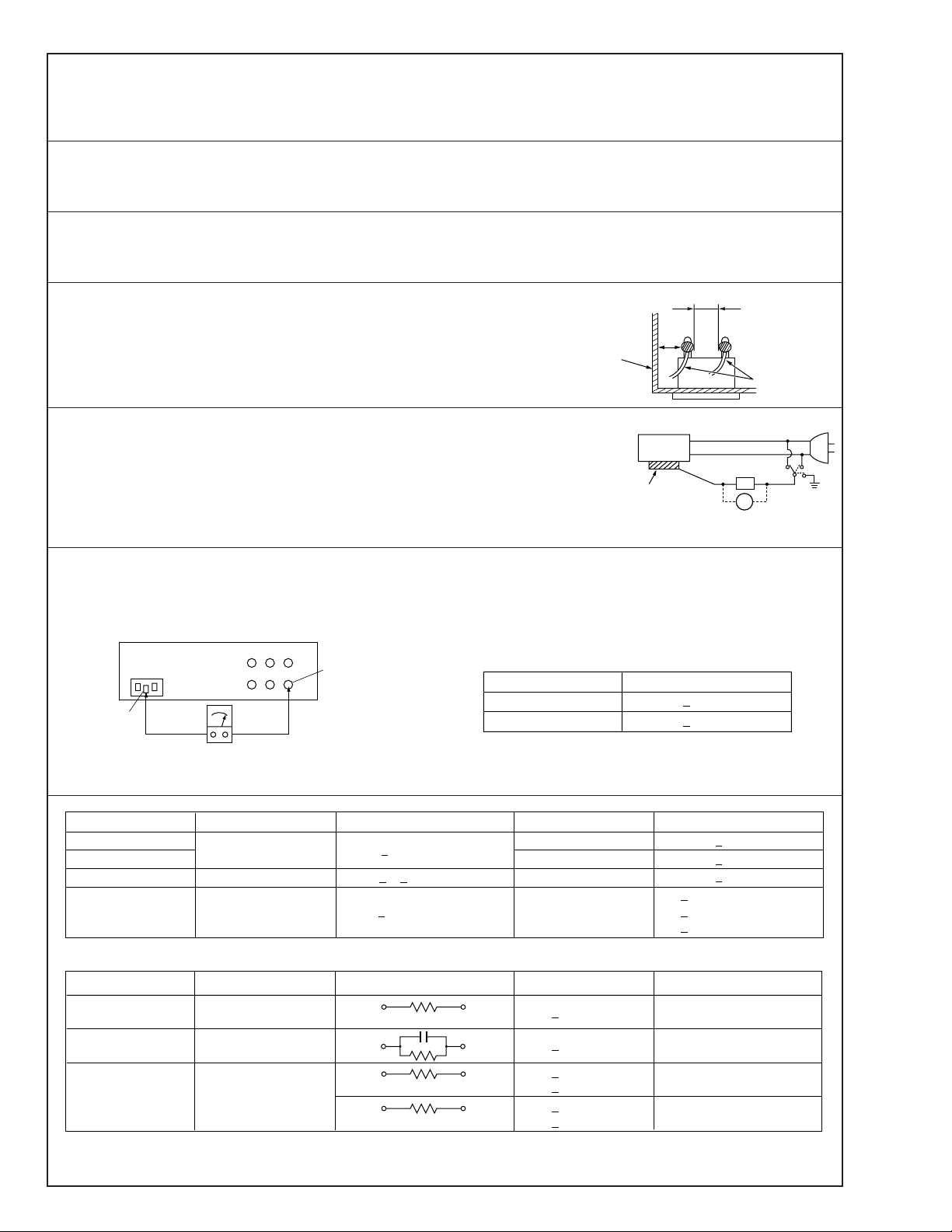
1. Insulation resistance test
Confirm the specified insulation resistance or greater between power cord plug prongs and
externally exposed parts of the set (RF terminals, antenna terminals, video and audio input
and output terminals, microphone jacks, earphone jacks, etc.). See table 1 below.
2. Dielectric strength test
Confirm specified dielectric strength or greater between power cord plug prongs and exposed
accessible parts of the set (RF terminals, antenna terminals, video and audio input and output
terminals, microphone jacks, earphone jacks, etc.). See table 1 below.
3. Clearance distance
When replacing primary circuit components, confirm specified clearance distance (d), (d’) between soldered terminals, and between terminals and surrounding metallic parts. See table 1
below.
Chassis
Fig. 8
4. Leakage current test
Confirm specified or lower leakage current between earth ground/power cord plug prongs
and externally exposed accessible parts (RF terminals, antenna terminals, video and audio
input and output terminals, microphone jacks, earphone jacks, etc.).
Measuring Method : (Power ON)
Insert load Z between earth ground/power cord plug prongs and externally exposed accessible parts. Use an AC voltmeter to measure across both terminals of load Z. See figure 9 and
following table 2.
5. Grounding (Class 1 model only)
Confirm specified or lower grounding impedance between earth pin in AC inlet and externally exposed accessible parts (Video in,
Video out, Audio in, Audio out or Fixing screw etc.).
Measuring Method:
Connect milli ohm meter between earth pin in AC inlet and exposed accessible parts. See figure 10 and grounding specifications.
AC inlet
Earth pin
Exposed accessible part
Grounding Specifications
Region
USA & Canada
Europe & Australia
Externally
exposed
accessible part
Grounding Impedance (Z)
d
d'
≤
Z 0.1 ohm
≤
Z 0.5 ohm
Power cord,
primary wire
Z
V
Fig. 9
ab
c
Milli ohm meter
Fig. 10
AC Line Voltage
100 V
100 to 240 V
110 to 130 V
110 to 130 V
200 to 240 V
100 V
110 to 130 V
110 to 130 V
220 to 240 V
Note: These tables are unofficial and for reference only. Be sure to confirm the precise values for your particular country and locality.
Region
Japan
USA & Canada
Europe & Australia R 10 MΩ/500 V DC
Region Load Z
Japan
USA & Canada
Europe & Australia
Table 2 Leakage current specifications for each region
Insulation Resistance (R)
≤
R 1 MΩ/500 V DC
≥≥
1 MΩ R 12 MΩ/500 V DC
≤
Table 1 Specifications for each region
1 kΩ
0.15 µF
1.5 kΩ
2 kΩ
50 kΩ
Dielectric Strength
AC 1 kV 1 minute
AC 1.5 kV 1 miute
AC 1 kV 1 minute
AC 3 kV 1 minute
AC 1.5 kV 1 minute
i 1 mA rms Exposed accessible parts
i 0.5 mA rms
i 0.7 mA peak
i 2 mA dc
i 0.7 mA peak
i 2 mA dc
2
≤
≤
≤
≤
≤
≤
(Class 2)
(Class 1)
Clearance Distance (d), (d')
≤
d, d' 3 mm
≤
d, d' 4 mm
≤
d, d' 3.2 mm
≤
d 4 mm
≤
d' 8 mm (Power cord)
≤
d' 6 mm (Primary wire)
a, b, cLeakage Current (i)AC Line Voltage
Exposed accessible parts
Antenna earth terminals
Other terminals
S40888-01
Page 5
SECTION 1
DISASSEMBLY
1.1 Before disassembling
1.1.1 Precaution
• Be sure to disconnect the power supply unit prior to mounting and soldering of parts.
• Prior to removing a component part that needs to disconnect its connector(s) and its screw(s), first disconnect the
wire(s) from the connector(s), and then remove the screw(s).
• Be careful not to damage the connector and wire etc. during connection and disconnection.
• When connecting the flat wire to the connector, be careful
with the flat wire direction.
• Be careful in removing or handling the part to which some
spacer or shield is attached for reinforcement or insulation.
• When replacing chip parts (especially IC parts), first remove
the solder completely to prevent peeling of the pattern.
• Tighten screws properly during the procedures. Unless
specified otherwise, tighten screws at a torque of 0.078Nom
(0.8kgfocm).
• The bracketed ( ) WR of the connector symbol are assigned
nos. in priority order and do not correspond to those on the
spare parts list.
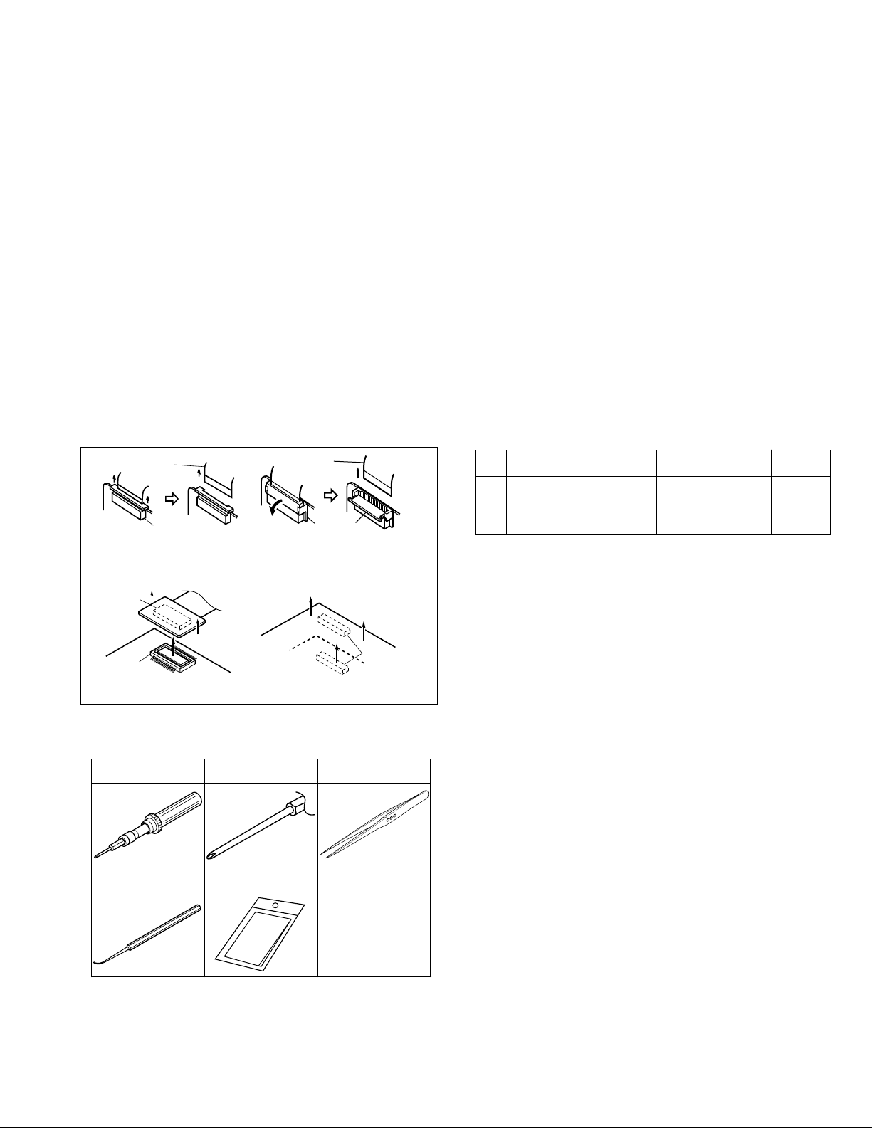
1.1.2 Disconnection of connectors (wires)
Flat wire
• Pull both ends of the connector in the arrow
B-B connector
B-B connector
FPC connector
direction, remove the lock and disconnect
the flat wire.
• Pull the board by both the sides in the direction of
the arrow for disconnecting the B-B connector.
• Extend the locks in the direction of the arrow for
unlocking and then pull out the wire. After removing the wire, immediately restore the locks
to their original positions because the locks are
apt to come off the connector.
Fig. 1-1-2a CONNECTOR
1.1.3 Required disassembling tools
Torque driver
YTU94088
Bit
YTU94088-003
Flat wire
FPC connector
lock
B-B connector
Tweezers
P-895
• Torque driver
Be sure to use to fastening the mechanism and exterior parts
because those parts must strictly be controlled for tightening torque.
• Bit
This bit is slightly longer than those set in conventional torque
drivers.
• Tweezers
To be used for removing and installing parts and wires.
• Chip IC replacement jig
To be used for replacement of IC.
• Cleaning cloth
Recommended the Cleaning cloth to wipe down the video
heads, mechanism (tape transport system), optical lens surface.
1.2 Removing the major parts
1.2.1 How to read the procedure table
This table shows the steps for disassembly of the major parts.
Reverse these steps when re-assembling them.
<Example>
Step
No.
[1] Top cover, 1-3a
(*1) (*2) (*3) (*4) (*5)
Part Name
Bracket 2(S1c)
Fig. No.
--------------------------
Point Note
4(S1a),(S1b),3(L1a), <Note 1a>
2(SD1a),(P1a),(W1a),
CN1(WR1a),
(*1) Order of steps in Procedure
When reassembling, perform the step(s) in the reverse or-
der.
(*2) Part name to be removed or installed.
(*3) Fig. No. showing procedure or part location.
(*4) Identification of part to be removed, unhooked, unlocked,
released, unplugged, unclamped or unsoldered.
P= Spring, W= Washer, S= Screw, L= Locking tab, SD=
Solder, CN**(WR**)= Remove the wire (WR**) from the con-
nector (CN**).
(*5) Adjustment information for installation
Chip IC replacement jig
PTS40844-2
Cleaning cloth
KSMM-01
Fig. 1-1-3a
1-1
Page 6

1.2.2 Disassembly procedure
[FINAL ASS'Y]
Step
No.
Part Name
Fig. No.
[1] FRONT ASS’Y(G) 1-2-2a (S132), 2(S131),
[2] UPPER ASS’Y(G) 1-2-2a 2(S124), COVER(DV),
[3] LOWER ASS’Y(F) 1-2-2a
[4] MAIN BOARD ASS’Y 1-2-2a 2(S117),
[5] MECHANISM ASS’Y 1-2-2a (S116),
Point Note
(S133), (S130),
TOP COVER, MIC COVER,
(S125), (S126), 2(S129),
MAIN CN115(WR101a),
HOLDER(DV/USB)
(S128), (S127),
BRACKET(TOP),
(S120), (S122), (S121),
3(S123),
MAIN CN112(WR102a),
MAIN CN113(WR102b)
MAIN CN114(WR103a),
MIC ASS’Y,
MAIN CN111(WR103b),
MAIN CN102(WR103c),
MAIN CN101(WR103d),
MAIN CN109(WR103e),
(S119), 3(S118)
SHIELD PLATE,
MAIN CN106(WR104a),
MAIN CN110(WR104b),
MAIN CN107(WR104c),
MAIN CN103(WR104d),
(L104a),
MAIN CN108(WR104e),
MAIN CN104(WR104f)
BKT(PRE-REC),
3(S115),
MECHA BKT ASS’Y
[WIRE CONNECTION]
WR No. CONNECTION
WR101a FRONT ASS’Y(G) STROBE CN6501 MAIN CN115
WR102a UPPER ASS’Y(G) SUB OPE UNIT — MAIN CN112
WR102b UPPER ASS’Y(G) MONITOR CN7601 MAIN CN113
WR103a — MIC ASS’Y — MAIN CN114
WR103b LOWER ASS’Y(F) C. OPE UNIT — MAIN CN111
WR103c LOWER ASS’Y(F) CCD — MAIN CN102
WR103d LOWER ASS’Y(F) BATT. TERM. — MAIN CN101
WR103e LOWER ASS’Y(F) SD CN301 MAIN CN109
WR104a MECHA ASS’Y SENSOR — MAIN CN106
WR104b MECHA ASS’Y HEAD — MAIN CN110
WR104c MECHA ASS’Y R. ENCODER — MAIN CN107
WR104d MECHA ASS’Y LOAD. MOTOR — MAIN CN103
WR104e MECHA ASS’Y CAP. MOTOR — MAIN CN108
WR104f MECHA ASS’Y DRUM MOTOR — MAIN CN104
[LOWER ASS’Y(F), LOWER ASS’Y(G)]
Step
No.
Part Name
Fig. No.
[1] OP F. ASS’Y 1-2-2b (S560),
(OP ASS’Y) (SD551a),
--------------------------
[2] VF ASS’Y(G) 1-2-2b 2(S559),
[3] SD BOARD ASS’Y 1-2-2b (S557),
[4]
SIDE OPE BOARD ASS’Y
[5] CASS.COVER ASS’Y 1-2-2b 4(S515)
(ARM ASS’Y) 2(S513),
1-2-2b 2(S512),
--------------------------
Point Note
SD CN302(WR551a),
(S558), BKT(OP)
CCD BOARD ASS’Y
SD CN304(WR552a)
SD CN303(WR553a)
CAMERA OPE UNIT,
(S522),
HOLDER(G.OUTER),
2(S514),
BKT(S.COVER/VF),
(S521),
SIDE COVER ASS’Y,
KNOB(DSC)
BATT.TERM.
[UPPER ASS’Y(G)]
Step
No.
Part Name
Fig. No.
[1] MONITOR ASS’Y(G) 1-2-2c (S614)*, (*601a)
--------------------------
[2] U.CASE ASS’Y 1-2-2c (S610),
Point Note
BKT(SPEAKER)*,
(S617), 2(S616),
2(S611), (WR601a)
2(S612),
COVER(TOP/UPP)L,
COVER(TOP/UPP)R
FRAME(UPPER) ASS’Y
(*601a) Mark*: This part was deleted on the way of production.
[MONITOR ASS’Y(G)]
Step
No.
Part Name
Fig. No.
[1] M.COVER ASS’Y 1-2-2d 3(S815), 2(S814)
[2]
MONITOR BOARD ASS’Y
1-2-2d (WR802a),
[3] HINGE UNIT ASS’Y 1-2-2d (S813)
[4] MONITOR CASE(3) 1-2-2d BACK LIGHT,
Point Note
MONITOR CN7601(WR802b),
MONITOR CN7602(WR802c),
2(SD802a),
(S812), 2(L802a)
LCD BKT(3INCH)2,
LCD MODULE,
LCD BKT(3INCH)1
[VF ASS’Y(G)]
Step
No.
Part Name
Fig. No.
[1] VFBW BOARD ASS’Y 1-2-2e FRAME(VF)2
[2] GUIDE(OUTER) ASS’Y 1-2-2e 2(S871),
Point Note
VFBW CN7002(WR851a),
2(S875)
(L852a),
COVER(VF) ASS’Y
1-2
Page 7

<M2> FINAL ASS'Y
TABLE OF SETTING TORQUE FOR SCREW DRIVER
PART NO.
115 116 117
OTHER SCREW
PROCESSING J7C MIC WIRE.
[J7C: Megapixel CCD MODEL]
PROCESSING K185 MIC WIRE.
[K185: Non Megapixel CCD MODEL]
SETTING TORQUE
0.07 ±0.01 N•m
0.09 ±0.01 N•m
THIS MIC WIRE PASS ON SPACER.
THIS MIC WIRE PASS OUTSIDE BKT(OP).
PROCESSING MIC WIRE TO THIS AREA
WHEN BUILT IN OF FRONT ASS'Y(F).
THIS AREA DON'T BITE ON MIC WIRE.
PASS MIC WIRE INSIDE BKT(OP).
PROCESSING MIC WIRE TO THIS AREA
WHEN BUILT IN OF FRONT ASS'Y(F).
THIS AREA DON'T BITE ON MIC WIRE.
Table.1 WIRE(FPC) CONNECTION TABLE
PWB NAME
MAIN PWB ASS'Y
MAIN PWB ASS'Y
MAIN PWB ASS'Y
MAIN PWB ASS'Y
MAIN PWB ASS'Y
MAIN PWB ASS'Y
MAIN PWB ASS'Y
MAIN PWB ASS'Y
MAIN PWB ASS'Y
MAIN PWB ASS'Y
MAIN PWB ASS'Y
MAIN PWB ASS'Y
MAIN PWB ASS'Y
MAIN PWB ASS'Y
132
COVER(DV)
127
111
HOLDER(DV/USB)
CN No.
CN101
CN102
CN103
CN104
CN106
CN107
CN108
CN109
CN110
CN111
CN112
CN113
CN114
CN115
UPPER ASS'Y(G)
U.CASE ASS'Y(G)
(Refer to the Exploded
view for this part.)
104
U
J
P
ASS'Y NAME
LOWER ASS'Y(F)
LOWER ASS'Y(F)
MECHA(A) ASS'Y
MECHA(A) ASS'Y
MECHA(A) ASS'Y
MECHA(A) ASS'Y
MECHA(A) ASS'Y
LOWER ASS'Y(F)
MECHA(A) ASS'Y
LOWER ASS'Y(F)
UPPER ASS'Y(G)
UPPER ASS'Y(G)
MIC ASS'Y
FRONT ASS'Y(G)
WIRE(FPC)NAME
BATT.TERM.
CCD
LOAD.MOTOR
DRUM MOTOR
SENSOR
R.ENC
CAPSTAN
SD PWB ASS'Y (CN301)
HEAD
CAMERA OPE
SUB OPE
MONI PWB
MIC WIRE
STROBE PWB
134
126
117
109
SHIELD PLATE
A
B1
MECHA BKT ASS'Y
108
<01> MAIN BOARD ASS'Y
115
R
N
V
K
R
L
G
[For Megapixel CCD MODEL]
MIC ASS'Y
135
129
102
FRONT ASS'Y(G)
F.COVER ASS'Y
(Refer to the Exploded
view for this part.)
T
S
Q
P
<M3> MECHANISM ASS'Y
BKT
116
(PRE-REC)
110
A
B2
B1
B2
(L104a)
MIC COVER
106
X1
TOP COVER
130
113
V
128
C
M
133
W
BRACKET(TOP)
114
W
D
LOWER ASS'Y(F)
(Refer to the Exploded
view for this part.)
103
E
H
X2
X1
U
X2
S
T
R
118
Q
J
K
L
118
119
NOTES
- While assembling the SET, don't touch CLEANER ROLLER portion of MECHA ASS'Y.
- PREVENT THE MOTOR FPC FROM ENTERING IN FERNALLY IN THE DRUM UPPER BASE.
- OPEN CASSETTE CAVER AND ASSEMBLE UPPER ASS'Y(G) AND FRONT ASS'Y(G).
112
123
124
HOOK THIS PART BETWEEN COVER(DV) AND FRONT COVER ASS'Y.
TABLE OF SETTING TORQUE FOR SCREW DRIVER
PART NO.
188 189
STRING IS CONNECTED
TO GRIP BELT.
SETTING TORQUE
0.069 ±0.007 N•m
FIG. PROCESSING TAG
H
122
131
COVER(ADJ)
183
191
TAG
A AFTER BERAKING INTO DOUBLE
FOLD PUT IN BETWEEN GRIP BELT
AND DUMMY(BATT.).
M
121
120
125
188
DUMMY BATT.
185
DUMMY BATTERY
COVER(JIG CONN)
Fig. 1-2-2a FINAL ASS’Y
RATING LABEL
184 189
LABEL SIDE
190
MEMORY CARD
FINAL ASS'Y LYH20619
CLEANER ASS'Y LYH20615
CASSETTE HOUSING
PUSH
187
LABEL(PUSH)
186
LABEL(HOUSING)
NOTE THE DIRECTION WHERE LABELS ARE STICKED.
1-3
Page 8

<M2> LOWER ASS'Y(F)
BKT(OP)
555
E
A
558
A
CONNECT
556
E-CARD WIRE
[K185: Non Megapixel CCD MODEL]
(WR551a)
CONCLUSION SCREW TORQUE TABLE
PART.NO
ALL SCREW
TORQUE
0.09 ±0.009 N•m
<M2> LOWER ASS'Y(G)
FPC
508
BATT.TERMINAL
507
BKT(OPJ7C)
555
G
OP F. ASS'Y
[K185]
(Refer to the
Exploded view
for this part.)
BENT 180" TO SIDE OF
REIN FOR CEMENT BOARD
OF CCD PWB ASS'Y
(WR551a)
(SD551a)
F
F
CONCLUSION SCREW TORQUE TABLE
PART.NO
514
ANOTHER SCREW
TORQUE
0.07 ±0.009 N•m
0.12 ±0.01 N•m
513
A
B
513
[J7C: Megapixel CCD MODEL]
558
G
(Refer to the
F
<03>
SD BOARD ASS'Y
557
559
(WR553a)
(WR552a)
B
559
OP F. ASS'Y
[J7C]
Exploded view
for this part.)
(SD551a)
E
D
HOLDER
(G.OUTER)
519
515
[For Non Megapixel CCD MODEL]
LOWER ASS'Y(G)
(Refer to the Exploded
view for this part.)
552
B
MIC ASS'Y
D
PROCESSING E-CARD WIRE (ONLY THE MODEL OF OP ASS'Y OF K185).
[K185: Non Megapixel CCD MODEL]
562
AFTER ASSEMBLY
BENT 180" PART
OF E-CARD WIRE.
560
C
BE CAREFUL NOT TO TOUCH BY THE FINGER, AND BE CAREFUL
NOT TO BEND THE TERMINAL FPC OF CAMERA OPE UNIT.
(USE TWEEZERS OR FINGER STALL)
(COUNTERMEASURE OF MIGRATION)
553
VF ASS'Y(G)
(Refer to the Exploded
view for this part.)
LOWER ASS'Y(F) LYH20622
KNOB(DSC)
503
<04>
SIDE OPE
BOARD ASS'Y
E
PROCESSING K185 OP ASS'Y AND MIC WIRE.
[K185: Non Megapixel CCD MODEL]
SPACER(A)
563
SPACER(A)
564
PASTE SO THAT SIDE OF
BKT(OP) MAYBE HIDDEN.
502
SIDE COVER ASS'Y
PROCESSING J7C OP ASS'Y.
[J7C: Megapixel CCD MODEL]
BENT
PASTE
567
SHEET(SHIELD)
SPACER(A)
PASTE TO CORNER OF OP ASS'Y.
565
SPACER(A)
565
SPACER(A)
DRAWING FOR SPACER STICKING.
LESS THAN 1 mm.
570
PASTE
SPACER
SPACER(A)
561
PASTE SPACER
TO COVER FPC OF OP ASS'Y.
PASTE ALONG THIS LINE.
PASTE SHIELD INSIDE FPC.
PASTE SPACER TO COVER
FPC OF OP ASS'Y.
INSID BRACKET PART
OF OP ASS'Y.
DON'T PASS MIC WIRE ON THIS SCREW.
PASTE TO
ACCORD.
PASS MIC WIRE INSIDE BKT(OP).
DRAWING FOR AFTER ASSEMBLY BKT(OP).
566
SPACER IS TWISTED AND
WIRE CAN'T BE SEEN.
LESS THAN 1 mm.
LOWER ASS'Y(G) LYH20620
PROCESSING GRIP BELT.
PASTE
568
561
SPACER IS NOT
PROTRUDED FROM
ARM BRACKET.
SHIELD(CCD)
BENT
SPACER(A)
514
521
522
ARM ASS'Y
504
SOLDERING
D
BKT(S.COVER/VF)
510
E
A
D
B
515
C
BE CAREFUL NOT TO TOUCH BY THE FINGER, AND BE CAREFUL
NOT TO BEND THE TERMINAL FPC OF CAMERA OPE UNIT.
(USE TWEEZERS OR FINGER STALL)
(COUNTERMEASURE OF MIGRATION)
Fig. 1-2-2b LOWER ASS’Y(F), LOWER ASSY(G)
C
512
(WR553a)
515
505
CASS.COVER ASS'Y
506
CAMERA OPE UNIT
E-CARD WIRE
509
PROCESSING BATT. FPC
SHEET(BAT.FPC)
SHOULD BE COVERED
TERMINAL PART.
516
SHOULD NOT BE
COVERED SCREW HOLE.
520
SPACER(A)
DRAWING FOR SPACER STICKING.
PASTE SPACER AFTER ATTACHING BATT. TERMINAL.
STICK ALONG
SPACER(A) SPACER(A)
THE EDGE OF ARM.
518
STICK ALONG
THE EDGE
OF ARM.
DON'T STICK OUT
BATT. FPC IN
ARM BRACKET.
GRIP BELT
511
PROCESSING CAP(GRIP BELT).
PROCESSING STICKER.
518
STICK ALONG
THE EDGE
OF ARM.
ATTACHING
CAP(GRIP BELT)
523
ATTACH
CAP(GRIP BELT)
THAT WIDTH IS WIDER
BECOME REAR SIDE.
LABEL(C.COVER)
517
1 ±1 mm
2 ±1 mm
1-4
Page 9

611
601
610
602
609
603
604
612
606
605
611
607
613
616
617
622
620
618
623
621
624
625
619
626
615
608
614
<M2> UPPER ASS'Y(G)
0.2 ±0.01 N•m
0.08 ±0.01 N•m
PART.NO
UPPER ASS'Y(G) LYH20626
3 ±1 mm
3 ±1 mm
E
F
D2
D1
C2
C1
D1
C1
E
F
J
H
A
B
D2
C2
A
B
J
H
G
G
MONITOR ASS'Y(G)
COVER(TOP/UPP)R
COVER(TOP/UPP)L
SUB OPE UNIT
MONI.LOCK ASS'Y
U.CASE ASS'Y
SPEAKER
FRAME(UPPER) ASS'Y
BRACKET(SPEAKER) *
SCREW *
COVER(TOP/UPP)R COVER(TOP/UPP)L
SPACER(A)
SPACER(A)
SPACER(A)
SPACER(A)
SPACER(A)
SPACER(A)
SPACER(A)
SHEET(SHIELD)
STICKER
(WR601a)
ANOTHER SCREW
TORQUE
CONCLUSION SCREW TORQUE TABLE
PASTE
UPWARDS
SHEET STICK ALONG
THE REINFORCEMENT
BOARD OF FPC.
SHEET STICK ALONG
THE CORNER OF FRAME.
DON'T SEPARATE.
DRAWING FOR SPACER STICKING.
LESS THAN 0.5mm
DON'T STICK OUT SPACER
IN UPPER CASE.
PASTE SPACER THIS CONVEX
IN UNDER SIDE.
PASTE SPACER
INSIDE BKT(UPPER).
STICK FPC SO THAT THERE
MAY BE NO CREVICE BET MEEN
THE HOLE OF IT IN THE RIGHT
SIDE OF THE HOLE RING.
THE SIDE OF THE
HOLE RING IS MET.
DON'T RUN A GROUND
OF UPPER CASE.
SHOULD BE COVERED
THIS CONVEX.
DON'T BE SEEN SPACER OUTSIDE
OF UPPER CASE.
STICK SPACER THAT FPC
MAY BE PRESSED DOWN.
PASTE SPACERS NOT TO COVER THESE HOLES.
THESE HOLES CAN BE SSEN.
PROCESSING MONITOR FPC.
SOLDER
2 POINT
SOLDERING
2 POINT
MOUNTAIN FOLDING
VALLEY FOLDING
MOUNTAIN FOLDING
VALLEY FOLDING
PROCESSING SUB OPE.
AFTER PASTING SUB OPE
PUSH TO THIS SLASH PART.
DON'T RUN A GROUND TO A LEVEL DIFFERENCE OF UPPER CASE.
PROCESSING SUB OPE FPC.
MOUNTAIN FOLDING
VALLEY FOLDING
VALLEY FOLDING
DON'T STICK OUT
SPACER IN
SUB OPE FPC.
STICK TO U.CASE.
(Refer to the Exploded
view for this part.)
Mark*: This part was deleted on the way of production.
Fig. 1-2-2c UPPER ASS’Y(G)
1-5
Page 10

<M2> MONITOR ASS'Y(G)
PROCESSING MONITOR FPC.
VALLEY FOLDING
DETECT SWITCH
SOLDER
808
4 POINT
SOLDER
2 POINT
MOUNTAIN FOLDING
VALLEY FOLDING
MOUNTAIN FOLDING
(WR802b)
IC
809
SOLDER
3 POINT
PUTTING OF SPACER(A).
MONITOR P. ASS'Y
THE END OF PWB IS
NOT OVER FLOWED.
(WR802a)
MONITOR P. ASS'Y
THE END OF PWB IS
NOT OVER FLOWED.
(2.5 INCH)
SPACER(A)
(3.0 INCH)
SPACER(A)
THIS HOLE IS NOT
PLUGGED UP.
819
THE END OF PWB IS
NOT OVER FLOWED.
819
CONCLUSION SCREW TORQUE TABLE
PART NO.
814
815
OTHER SCREW
LCD BKT(2.5)2
LCD BKT(3INCH)2
806
SETTING TORQUE
0.2 ±0.02 N•m
0.055 ±0.01 N•m
0.07 ±0.01 N•m
LCD MODULE
(WR802c)
LCD BKT(2.5)1
LCD BKT(3INCH)1
810
805
HINGE UNIT ASS'Y
807
MONITOR CASE(25)
MONITOR CASE(3)
SPACER(A)
816
802
C1
PASTE
D1
X
813
F
A2
B2
A1
a
B1
A2
F
C2
Z
B2
D2
E2
815
811
BACK LIGHT
<06> MONITOR BOARD ASS'Y
Z
(L802a)
814
a
I.SHEET(M.COVER)M.COVER ASS'Y
803
804
A1
C1
D1
815
B1
PASTE
E1
LCD MODULE S.A.
1. PUTTING OF SPACER(A)
LCD BKT(2.5INCH)2 LCD BKT(3INCH)2
SPACER(A)
818
SPACER(A)
817
SPACER(A)
818
RANGE OF PUTTING
MASKING AREA IN ENGRAVE LINE CETAINLY.
DON'T STICK OUT SPACER(A) IN LCD DISPLAY FACE.
2. PUTTING OF LCD MODULE (2.5 & 3.0 INCH)
- PEEL OFF PROTECTION SHEET OF SPACER(A) ON LCD BKT2.
- CONFORM THAT LCD MODULE IS SUITABLE FOR POSITION OF
LCD BKT2 AND PUT TWO PARTS.
(L802a)
812
X
(SD802a)
(SD802a)
SPACER(A)
817
C2
D2
816
SPACER(A)
PASTE
E1
E2
NOTES
- SHOULD BE NO SCRATCHES, NO DUSTS AND OTHER ON COSMETIC COMPONENTS.
- SHOULD BE NO FLOATAGE, MISSING PARTS OF THE SCREW.
- BE GODS ALL-IN WHEN M.COVER ASS'Y IS BUILT IN OF FPC AND WIRE, ETC.
- SHOULD BE PASTE SYMBOL"804" OF THE REVERSE SIDE OF M.COVER.
MONITOR ASS'Y(G) LYH20625
SPACER(A)
818
818
SPACER(A)
LCD BKT(2.5INCH)2
& LCD BKT(3INCH)2 LCD BKT(2.5INCH)2
SPACER(A)
STICK ACCORDING
TO THE END OF
THIS LCD BKT2
820
TURN UP
821
SPACER(A)
TURN UP
1-6
Fig. 1-2-2d MONITOR ASS’Y(G)
Page 11

<M2> VF ASS'Y(G)
PROCESSING SPACER(A)
875
GUIDE SCREW
871
DON'T RUN A GROUND ON
THIS CONNECTOR.
E-CARD WIRE
GUIDE(OUTER)
861
GUIDE(OUTER) ASS'Y
A
872
860
B
V.ADJ.PLATE
S.PLATE
VFBW BOARD ASS'Y
VFCL BOARD ASS'Y
CASE(VF) ASS'Y
GUIDE SCREW
871
870
865
866
B.LIGHT CASE
B.LIGHT CASE
BLOW OUT AIR.
852
STP RING
BLOW OUT AIR.
SHEET(DIFF)
853
(WR851a)
LENS HOLDER ASS'Y
868
869
(L852a)
A
SHEET(POLA)
CUSHION(LCD)
CUSHION(LCD)3
854
BLOW OUT AIR.
857
COMPRES.SPRING
862
B
LCD MODULE
BLOW OUT AIR.
PASTE TAPE TO LCD RESPECT,
856
AND PEEL OFF TAPE.
S.GUIDE ASS'Y
SHEET(LENS)
864
LCD HOLDER
LCD HOLDER2
BLOW OUT AIR.
855
858
EYE CUP
863
CONCLUSION SCREW TORQUE TABLE
PART.NO
ALL SCREW
FRAME(VF)
FRAME(VF)2
BLOW OUT AIR.
SHEET(POLA)
PASTE INSIDE THAT EXFOLIATION
854
PAPER'S COLOR IS TRANSPARENT.
TORQUE
0.09 ±0.009 N•m
859
SHEET HOLD
BLOW OUT AIR.
TURN TURN
EARTH SHEET
876
PASTE
FRAME(VF)2
DRAWING FOR EARTH SHEET STICKING.
LESS THAN 1mm.
874
B/W VF COLOR VF
SPACER(A)
V.ADJ.KNOB
Fig. 1-2-2e VF ASS’Y(G)
1.3 Manually removing the cassette tape
The following procedure describes a simplified method of ejecting the cassette tape in case it is not possible to eject it, due
to an electrical failure.
Be careful not to damage any of the parts or the tape when
performing repairs or maintenance work.
(1) Remove the Power Unit (battery, DC code, etc.) from the
main unit.
(2) Open the Cassette cover.
(3) Attach a piece of PVC tape at the front of the Cassette hous-
ing.
This helps prevent the tape from being damaged when the
Cassette housing assembly is moved upward at the unload-
ing end.
(4) Apply DC3V to the electrode on the top surface of the Load-
ing motor assembly to set the Mechanism assembly to the
eject mode.
Unloading end is eject mode.
(5) If there is any slack tape in the tape transport system, wind
it inside the cassette tape by turning the Reel disk (SUP)
from the backside of the Slide deck assembly.
(6) Peel off the PVC tape and take out the cassette tape from
the Cassette housing.
Make sure that grease or a similar substance is not attached
to the surface of the tape.
Similarly, also make sure that grease or a similar substance
is not attached on the Mechanism assembly.
867
VF ASS'Y(G) LYH20621
PVC TAPE
REEL DISK
ASSY (SUP)
Fig. 1-3a
SHUOLD BE MATCHED KNOB
TO FULL LEFT SIDE.
(REFER TO THE CHART)
DIOPTER ADJUSTMENT CONTROL
(DC3V)
1-7
Page 12

1.4EMERGENCY DISPLAY
Whenever some abnormal signal is input to the syscon CPU,
an error number (E01, as an example) is displayed on the LCD
monitor or (in the Electronic view finder).
In every error status, such the message as shown below alternately appear over and over.
In an emergency mode, all operations except turning on/off the
Power switch are ineffectual.
E01
UNIT IN
SAFEGUARD MODE
E01
REMOVE AND
REATTACH BATTERY
LCD
display
E01 LOADING In the case the encoder position is not shifted to
E02 UNLOADING In the case the encoder position is not shifted to
E03 TU & SUP REEL FG In the case no REEL FG is produced for 4 sec-
E04 DRUM FG In the case there is no DRUM FG input in the
E05 — — —
E06 CAPSTAN FG In the case no CAPSTAN FG is produced in the
Emergency
mode
Details Possible cause
the next point though the loading motor has rotated in the loading direction for 4 seconds or
more. This error is defined as [E01].
the next point though the loading motor has rotated in the unloading direction for 4 seconds or
more. This error is defined as [E02].
onds or more in the capstan rotation mode after
loading was complete, the mechanism mode is
shifted to STOP with the pinch roller set off. This
error is defined as [E03].
However, no REEL EMG is detected in the SLW/
STILL mode.
drum rotation mode for 4 seconds or more.
This error is defined as [E04], and the mechanism mode is shifted to STOP with the pinch roller
set off.
capstan rotation mode for 2 seconds or more.
This error is defined as [E06], and the mechanism mode is shifted to STOP with the pinch roller
set off.
However, no CAPSTAN EMG is detected in the
STILL/FF/ REW mode.
1. The mechanism is locked during mode shift.
2. The mechanism is locked at the mechanism loading end, because the encoder
position is skipped during mechanism mode shift.
3. No power is supplied to the loading MDA.
1. The mechanism is locked during mode shift.
2. The mechanism is locked at the mechanism loading end, because the encoder
position is skipped during mechanism mode shift.
1. The idler gear does not engage with the reel disk well.
2. Though the idler gear and reel disk are engaged with each other, the tape is not
wound because of overload to the mechanism.
3. No FG pulse is output from the reel sensor.
4. No power is supplied to the reel sensor.
5. Tape transport operation takes place with a cassette having no tape inside.
6. The tape slackens and no pulse is produced until the slack is taken up and the
tape comes into the normal status.
1. The drum cannot be started or drum rotation is stopped because tape transport
load is too high.
1) Tape tension is extremely high.
2) The tape is damaged or soiled with grease, etc.
2. The DRUM FG signal is not received by the syscon CPU.
1) Disconnection in the middle of the signal line.
2) Failure of the DRUM FG pulse generator (hall element).
3. No drum control voltage is supplied to the MDA.
4. No power is supplied to the DRUM MDA.
1. The CAPSTAN FG signal is not received by the syscon CPU.
1) Disconnection in the middle of the signal line.
2) Failure of the CAPSTAN FG pulse generator (MR element).
2. No capstan control voltage is supplied to the MDA.
3. No power is supplied to the CAPSTAN MDA.
4. The capstan cannot be started or capstan rotation is stopped because tape
transport load is too high.
1) Tape tension is extremely high. (Mechanical locking)
2) The tape is damaged or soiled with grease, etc. (Tape tangling occurs, etc.)
Fig. 1-4a
1-8
Page 13

SECTION 3
ADJUSTMENT
3.1 Before adjustment
3.1.1 Precaution
This model does not contain adjustment controls (VR).
General deck system, camera system and monitor system adjustment are not required. However, if circuit board mounting
the EEPROM needs replacement, please use original EEPROM
on to new board. Then adjustment are not required. And if parts
such as the following need replacement, special computerized
adjustment are required. Electrical adjustment with personal
computer is setup and it adjusts using a service support system. Please contact to JVC Service for detail information.
• OP BLOCK ASSEMBLY
•
EEPROM (IC1003 of MAIN board) [Megapixel CCD MODEL]
•
EEPROM (IC1005 of MAIN board) [Non Megapixel CCD MODEL]
3.1.3 Required adjustment tools
Torque driver
YTU94088
Chip IC replacement jig
PTS40844-2
Bit
YTU94088-003
Cleaning cloth
KSMM-01
Tweezers
P-895
Guide driver (Hexagonal)
D-770-1.27
In the event of malfunction with electrical circuits, troubleshooting with the aid of proper test instruments most be done first,
and then commence necessary repair, replacement and adjustment, etc.
• In case of wiring to chip test points for measurement, use IC
clips, etc. to avoid any stress.
• Since connectors are fragile, carefully handle them in discon-
necting and connecting.
• In the following work, use the patch cords as required. For
details of the patch cords, see the "BOARD INTERCONNECTIONS" (CHARTS AND DIAGRAMS).
3.1.2 Required test equipments
• AC power adapter
• Color television or monitor
• Oscilloscope
(dual-trace type, observable 100 MHz or higher frequency)
It is recommended to use one observable 300 MHz or higher
frequency.
• Digital voltmeter
• Frequency counter (with threshold level adjuster)
• Personal computer
INF adjustment lens
YTU92001B
Light box assembly
YTU93096A
Alignment tape
MC-*
Service support system
YTU94057-**
INF lens holder
YTU94087
Gray scale chart
YTU94133A
PC cable
QAM0099-***
Jig connector cable
YTU93106B
Camera stand
YTU93079
Color bar chart
YTU94133C
Communication cable
YTU93107A
Extension connector
YTU94145C-30
Table 3-1-3a
3-1
Page 14

• Torque driver
Be sure to use to fastening the mechanism and exterior parts
because those parts must strictly be controlled for tightening
torque.
• Bit
This bit is slightly longer than those set in conventional torque
drivers.
• Tweezers
To be used for removing and installing parts and wires.
• Chip IC replacement jig
To be used for replacement of IC.
• Cleaning cloth
Recommended the Cleaning cloth to wipe down the video
heads, mechanism (tape transport system), optical lens surface.
• Guide driver (Hexagonal)
To be used for mechanism compatibility adjustment.
• INF adjustment lens
To be used for adjustment of the camera system.
For the usage of this tool, refer to the Service Bulletin No. YASB-10035.
• INF lens holder
To be used together with the Camera stand for operating the
Videocamera in the stripped-down condition such as the status without the exterior parts or for using commodities that
are not yet conformable to the interchangeable ring.
For the usage of this tool, refer to the Service Bulletin No. YASB-10035.
• Camera stand
To be used together with the INF adjustment lens holder.
For the usage of this tool, refer to the Service Bulletin No. YASB-10035.
• Light box assembly
To be used for adjustment of the camera system.
For the usage of this tool, refer to the Service Bulletin No. YASB-10035.
• Gray scale chart
To be used for adjustment of the camera system.
For the usage of this tool, refer to the Service Bulletin No. YASB-10035.
• Color bar chart
To be used for adjustment of the camera system.
For the usage of this tool, refer to the Service Bulletin No. YASB-10035.
• Alignment tape
To be used for mechanism compatibility adjustment.
MC-1 [For NTSC model]
MC-2 [For PAL model]
• PC cable
To be used to connect the Videocamera and a personal computer with each other when a personal computer is used for
adjustment.
QAM0099-001 [For J* model]
QAM0099-002 [For U* and K* models]
QAM0099-003 [For E* models]
QAM0099-005 [For A* models]
• Communication cable
Connect the Communication cable between the PC cable and
Jig connector cable when performing a PC adjustment.
• Service support system
To be used for adjustment with a personal computer. Software can be downloaded also from JS-net.
• Jig connector cable
Connected to CN for Jig of the circuit board and used for electrical adjustment, etc.
• Extension connector
Connect this extension connector to the connector of the Jig
connector cable for extending the cable connector.
3-2
Page 15

3.1.4 Jig connector cable connection
ENV_OUT
HID1
Flatten the waveform.
Misalignment of guide roller
height on the take-up side
Misalignment of guide
roller height on the
supply side
3.1.4.1 Preparation
The Jig connector cable (YTU93106B) has been provided for
GR-DV2000 series. And it has been connected only 9 terminals for low cost, although it has 30 terminals.
Now it can be used another series camcorder, but all the
terminals have to be connected by soldering wires. Refer to
the Service Bulletin (No. YA-SB-10082), and connect all the
terminals.
3.1.4.2 Connection
GUIDE ROLLER (SUP)
GUIDE ROLLER (TU)
NCNCNC
C
CJIG_RST
AL_3VSYS
B
CJIG_RST
AL_3VSYS
A
REG_3V
SRV_RX
MAIN CN105
JIG CONN.
NCNCNC
DRST
SRV_TX
TXD2
CVF_B
CVF_R
VPL
VCK
SPA
RXD2
CVF_G
MON_B
VIDH
MON_B
CVF_G
MON_B
GND
JLIP_RX
MONI_CHG
GND
JLIP_RX
MONI_CHG
GND
JLIP_RX
MONI_CHG
GND
V_OUT
GND
V_OUT
GND
V_OUT
VIDL
VIDL
VIDL
MON_G
MON_G
MON_G
A : Mega pixel with DSC model
B : Non Mega pixel with DSC model
PB_CLK
JLIP_TX
PB_CLK
JLIP_TX
PB_CLK
JLIP_TX
HID1
HID1
HID1
GND
GND
GND
ATFI
ENV_OUT
ATFI
ENV_OUT
ATFI
ENV_OUT
I_MTR
DISCRI
MAIN_VCO
I_MTR
DISCRI
MAIN_VCO
DISCRI
AL_3VSYS
MAIN_VCO
IF_TX
EXMOD_1
IF_TX
EXMOD_1
VPPC
VPPD
FS_PLL
MMOD_1
MMOD_0
FS_PLL
MMOD_1
MMOD_0
IF_TX
FS_PLL
CJING_RST
C : Non Mega pixel without DSC model
Fig. 3-1-4-2b Schematic diagram of Jig CN
3.2 Mechanism compatibility adjustment
3.2.1 Tape pattern check
(1) Play back the tape for compatibility adjustment.
(2) Apply the external trigger signal to HID1, to observe the
waveform of the ENV_OUT.
(3) Set to the manual tracking mode (ATF OFF).
(4) Make sure that there is no significant level drop of the
waveform caused by the tracking operation, with its gen-
erally parallel and linear variation ensured. Perform the fol-
lowing adjustments when required.
(5) Reduce the waveform by the tracking operation. If a drop
in level is found on the left side, turn the guide roller (sup-
ply side) to make the waveform linear.
If a drop in level is on the right side, likewise turn the guide
roller (take-up side) to make it linear.
(6) Unload the cassette tape once, play back the tape again
and confirm that the waveform is flat.
(7) Record at the recording tape, and play back the recorded
signal.
(8) Confirm that the waveform is flat.
TO JIG CONNECTOR
JIG
CONNECTOR
CABLE
COMMUNICATION
CABLE
RED
WHITE
BLACK
COMMUNICATION
CABLE
JIG CONNECTOR
TO JLIP_RX
TO JLIP_TX
TO GND
Fig. 3-1-4-2a Cable connection
JIG CONNECTOR
SERVICE SUPPORT SYSTEM
PC CABLE
TO COMMUNICATION
CABLE
RS232C
COM PORT
TO ENV_OUT
TO HID1
MENU
Fig. 3-2-1a
PERSONAL COMPUTER
OSCILLOSCOPEJIG CONNECTOR
Fig. 3-2-1b
3.3 Electrical adjustment
Adjustment is performed by using personal computer. Read
README.TXT file to use the software for Service support system properly.
As for the connection of cables, see Fig. Cable connection.
3-3
Page 16

JVC SERVICE & ENGINEERING COMPANY OF AMERICA
DIVISION OF JVC AMERICAS CORP.
www.jvcservice.com(US Only)
JVC CANADA INC.
Head office
:
21 Finchdene Square Scarborough, Ontario M1X 1A7
(416)293-1311
Printed in Japan
0306 VP
 Loading...