

Page 1
SECTION 4
CHARTS AND DIAGRAM
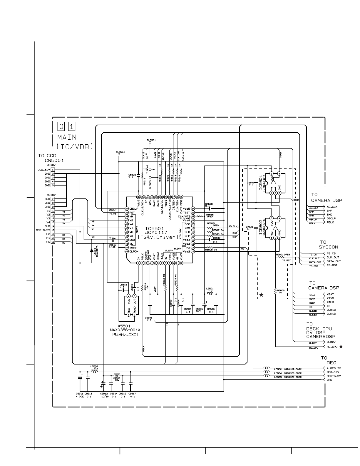
4.1 MAIN (TG/VDR) SCHEMATIC DIAGRAM
Note1 : How to find the page showing the continuative schematic diagram
5
Note2 : mark ★ means modified points.
4
Example) TO MAIN (page 4-XX) : Refer to the GR-DVL805U service manual (No.86550).
TO MAIN (Page 4-XX) : Refer to this service manual.
3
2
1
ABC D
4-1
Page 2
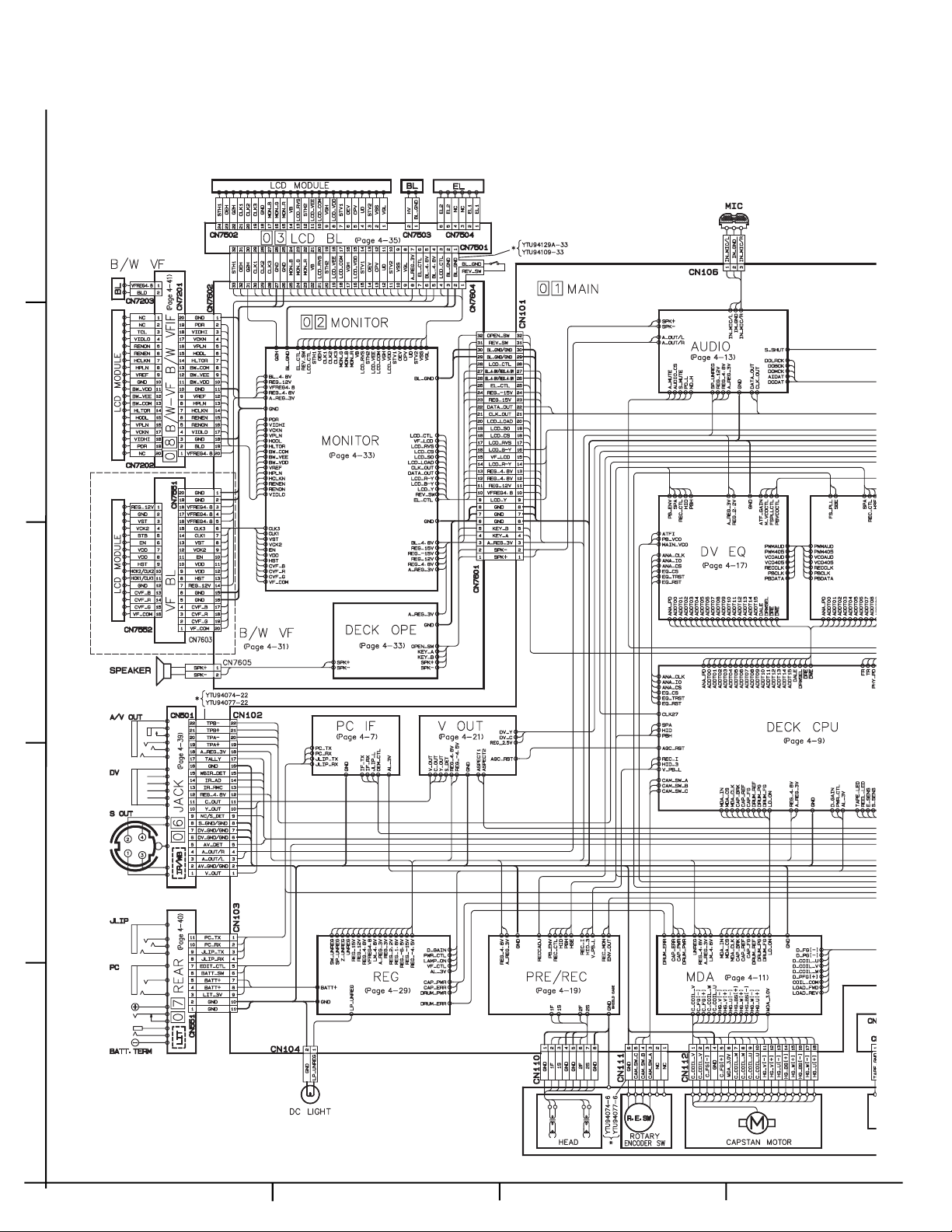
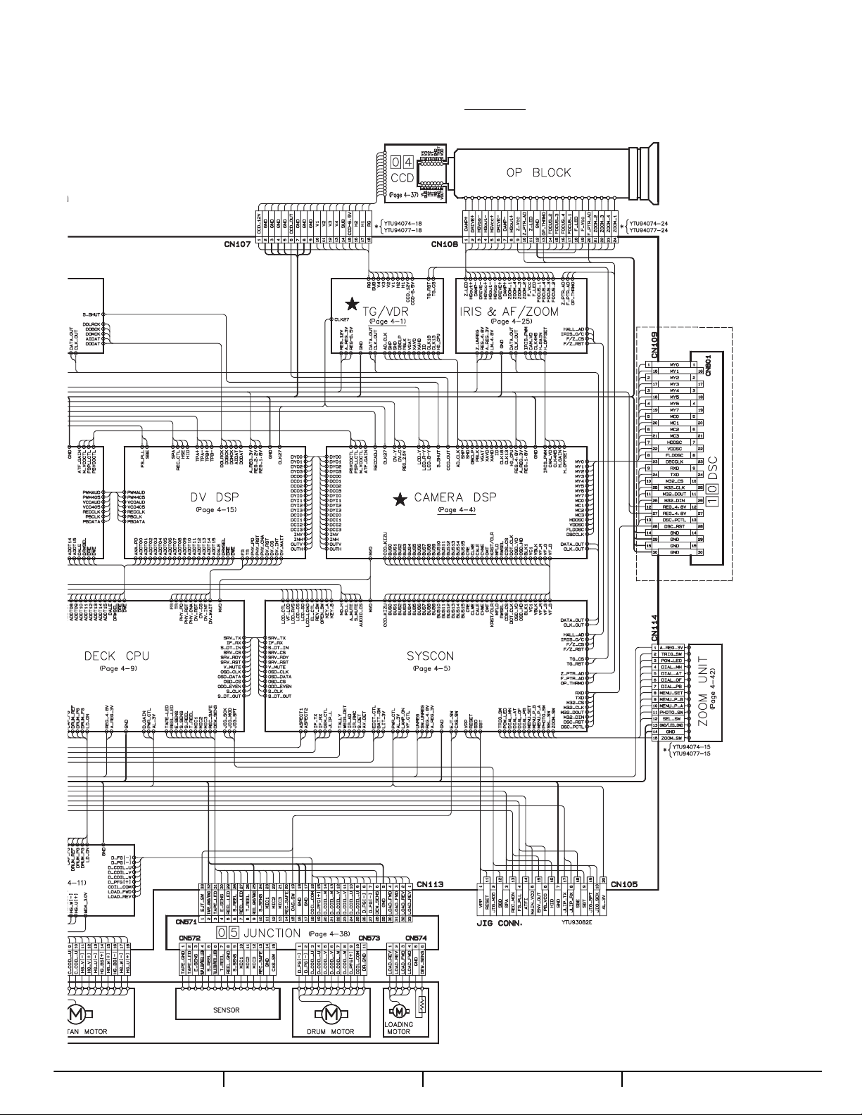
4.2 BOARD INTERCONNECTIONS
5
4
3
2
1
4-2
ABC D
Page 3
Note1 : How to find the page showing the continuative schematic diagram
Example) TO MAIN (page 4-XX) : Refer to the GR-DVL805U service manual (No.86550).
TO MAIN (Page 4-XX) : Refer to this service manual.
★
Note2 : mark
means modified points.
DE FG
4-3
Page 4
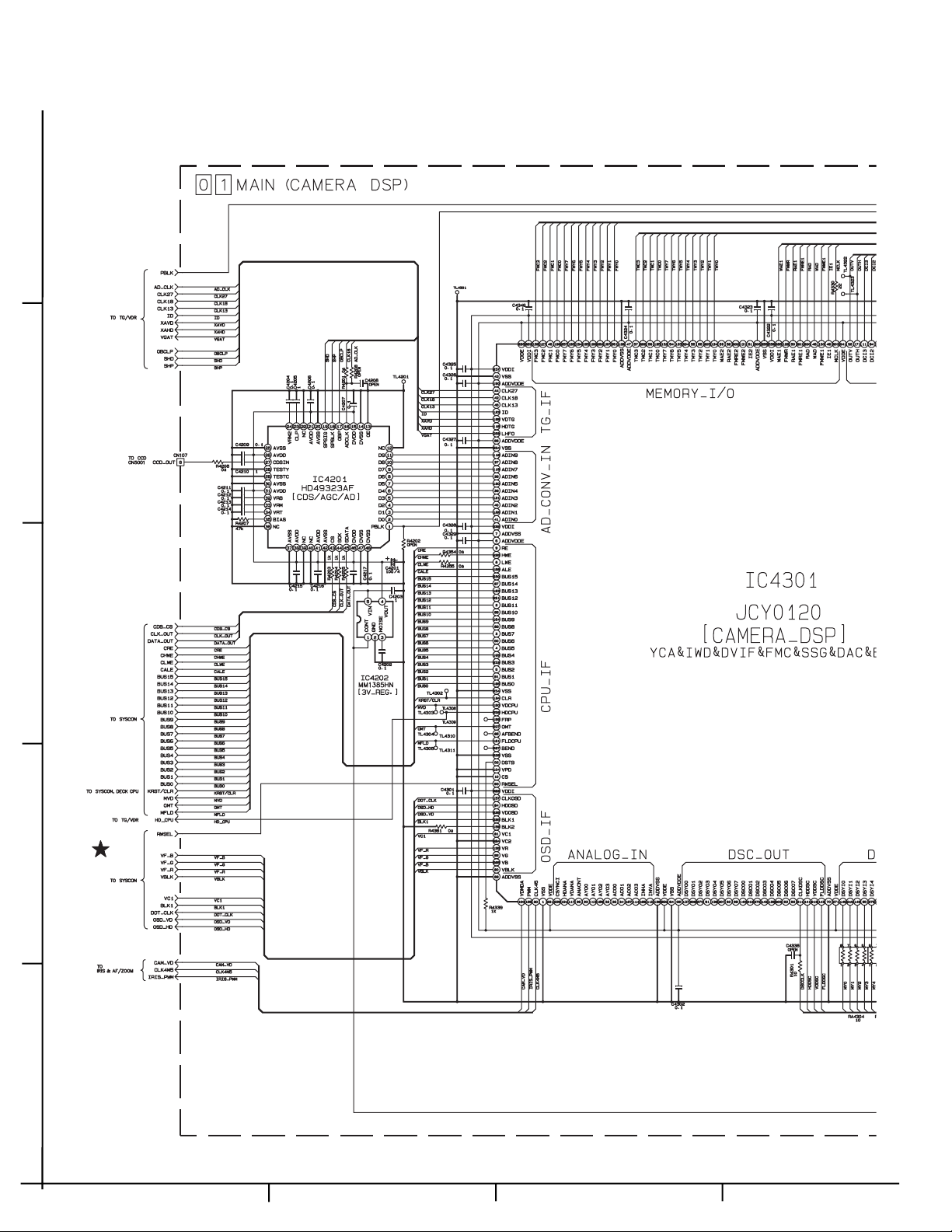
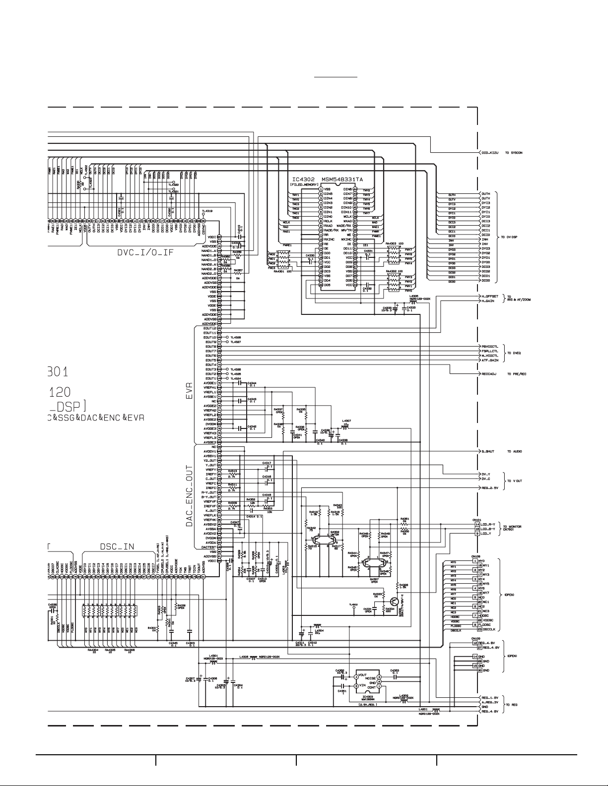
4.3 CAMERA DSP SCHEMATIC DIAGRAM
5
4
3
2
1
4-4
ABC D
Page 5
Note1 : How to find the page showing the continuative schematic diagram
Example) TO MAIN (page 4-XX) : Refer to the GR-DVL805U service manual (No.86550).
TO MAIN (Page 4-XX) : Refer to this service manual.
★
Note2 : mark
means modified points.
DE FG
4-5
Page 6

4.4 JACK CIRCUIT BOARDS
06 JACK PWB YB10278-01-02
COMPONENT SIDE (A)
FOIL SIDE (B)
4-6
Page 7

4.5 JUNCTION CIRCUIT BOARDS
05 JUNCTION PWB YB10278-01-02
4.6 REAR CIRCUIT BOARDS 07 REAR PWB YB10278-01-02
–– JUNCTION ––
COMPONENT SIDE (A)
FOIL SIDE (B)
–– REAR ––
COMPONENT SIDE (A)
FOIL SIDE (B)
4-7
Page 8

4.7 MAIN CIRCUIT BOARDS
COMPONENT SIDE (A)
01 MAIN PWB YB10277-01-03
4-8
Page 9

4-9
Page 10

MAIN CIRCUIT BOARDS
4-10
Page 11

FOIL SIDE (B)
01 MAIN PWB YB10277-01-03
4-11
Page 12

COMPONENT PARTS LOCATION GUIDE <MAIN> YB10277-01-03
REF.NO. LOCATION
CAPACITOR
C1001 B C 3C
C1002 B C 3B
C1003 B C 3A
C1004 B C 4A
C1008 B C 2B
C1009 B C 3B
C1010 B C 3B
C1011 B C 3A
C1012 B C 2C
C1013 B C 1C
C1014 B C 2B
C1015 B C 1C
C1016 B C 3A
C1017 B C 4A
C1019 B C 1B
C1021 B C 2B
C1022 B C 4B
C1023 B C 4B
C1024 B C 4B
C1026 B C 4A
C1027 B C 4A
C1028 B C 4A
C1031 B C 4B
C1032 B C 2B
C1034 B C 1B
C1035 B C 3B
C1036 B C 4A
C1037 B C 1A
C1038 B C 3A
C1039 B C 3A
C1040 B C 2B
C1041 B C 4A
C1042 B C 2B
C1043 B C 3C
C1301 B C 3C
C1302 B C 3B
C1303 B C 3B
C1304 B C 3B
C1305 B C 3B
C1306 B C 3B
C1307 B C 4C
C1401 A C 2B
C1402 A C 2B
C1411 A C 2B
C1412 A C 2B
C1413 A C 2B
C1414 A C 2B
C1415 A C 2B
C1416 A C 2B
C1417 A C 2B
C1418 B C 1B
C1419 B C 1B
C1420 A C 3A
C1421 A C 3A
C1422 A C 3B
C1423 A C 3B
C1424 B C 1B
C1425 A C 3B
C1601 A C 1B
C1602 A C 1B
C1603 A C 1B
C1605 A C 1A
C1606 A C 1B
C1607 A C 1B
C1610 A C 1A
C1611 A C 1A
C1612 A C 1A
C1613 A C 1A
C1614 A C 1C
C1615 A C 1B
C1616 A C 1B
C1617 A C 1B
C1618 A C 1B
C1619 A C 1B
C1620 A C 1B
C1621 A C 1B
C1622 A C 1B
C1623 A C 1B
C1624 A C 1B
C1625 A C 1B
C1626 A C 1B
C1627 A C 1A
C1628 A C 1B
C1632 A C 1B
C1633 A C 2B
C1635 A C 2B
C1638 A C 1A
C1639 A C 1A
C1640 A C 1B
C1641 A C 1B
C1642 A C 1A
C2101 B C 5C
C2103 B C 4C
C2105 B C 5C
C2201 B C 5C
C2202 B C 5C
C2203 B C 4C
C2205 B C 4C
C2207 B C 4C
REF.NO. LOCATION REF.NO. LOCATION
C2208 B C 4C
C2209 B C 4C
C2210 B C 4C
C2211 B C 4C
C2212 B C 4C
C2213 B C 4C
C2214 B C 5C
C2216 B C 4C
C2217 B C 4C
C2401 B C 5C
C2402 B C 4D
C2403 B C 5C
C2601 B C 4D
C2602 B C 4D
C2603 B C 4D
C2604 B C 4D
C2605 B C 4D
C2606 B C 4D
C2607 B C 5C
C2608 B C 4C
C2609 B C 5C
C2610 B C 4C
C2617 B C 5C
C2618 B C 5C
C2619 B C 4D
C2620 B C 4C
C2622 B C 4C
C2623 B C 4C
C2624 B C 5C
C2625 B C 4C
C2626 B C 5C
C2627 B C 4C
C2628 B C 5C
C2629 B C 4C
C2630 B C 5D
C2631 B C 4C
C2632 B C 5C
C2633 B C 4C
C2634 B C 5C
C2635 B C 4C
C2636 B C 5C
C2637 B C 4C
C3001 A C 3B
C3002 A C 3B
C3003 A C 3B
C3004 A C 3B
C3005 A C 3B
C3006 A C 3C
C3007 A C 4C
C3009 A C 4B
C3010 A C 4B
C3011 A C 4B
C3012 A C 4B
C3022 A C 3B
C3023 A C 4B
C3027 A C 4C
C3028 A C 4C
C3035 A C 4B
C3037 A C 4B
C3038 A C 4C
C3040 A C 4B
C3041 A C 4B
C3042 A C 4B
C3047 A C 4C
C3048 A C 4C
C3049 A C 4B
C3050 A C 4B
C3101 A C 5C
C3102 A C 5C
C3103 A C 5C
C3104 A C 5C
C3105 A C 5C
C3106 A C 5C
C3107 A C 5C
C3108 A C 4C
C3109 A C 5C
C3203 A C 3C
C3204 A C 3C
C3205 A C 3C
C3207 A C 3C
C3208 A C 3C
C3211 A C 3C
C3212 A C 3C
C3213 A C 3C
C3214 A C 2C
C3215 A C 2B
C3217 A C 3C
C3218 A C 3C
C3219 A C 2B
C3220 A C 3B
C3221 A C 4D
C3222 A C 2B
C3223 A C 2C
C3224 A C 2C
C3227 A C 3D
C3228 A C 3D
C3229 A C 3D
C3230 A C 3D
C3231 A C 4D
C3232 A C 4D
C3301 A C 3D
C3302 A C 3D
C3303 A C 4D
C3304 A C 4D
C3305 A C 3D
C3306 A C 3D
C3307 A C 4C
C3308 A C 4D
C3309 A C 3D
C3310 A C 3D
C3311 A C 4D
C3312 A C 4D
C3313 A C 4D
C3314 A C 4D
C3316 A C 4D
C3317 A C 4D
C3318 A C 4D
C3319 A C 4D
C3320 A C 4D
C3321 A C 3C
C3322 A C 3D
C3323 A C 3D
C3324 A C 3C
C3326 A C 3D
C3327 A C 3D
C3328 A C 4D
C3331 A C 3D
C3332 A C 3D
C3333 A C 3D
C3334 A C 3D
C3335 A C 3D
C3336 A C 3D
C3337 A C 3D
C3501 B C 3C
C3502 B C 3C
C3503 B C 3C
C3504 B C 3C
C3505 B C 3C
C3506 B C 3C
C3507 B C 3C
C3508 B C 3C
C3509 B C 3C
C3510 B C 3C
C3511 B C 3C
C3512 B C 3C
C3513 B C 4C
C3514 B C 3C
C3515 B C 3C
C3516 B C 3C
C3517 B C 3C
C3518 B C 3C
C3519 B C 3D
C3520 B C 3D
C3521 B C 3D
C3522 B C 3C
C3523 B C 3D
C3524 B C 3D
C3525 B C 3C
C3526 B C 3C
C3527 B C 3C
C3528 B C 3C
C3529 B C 3C
C3530 B C 3C
C3531 B C 3C
C3532 B C 3D
C3533 B C 3C
C3534 B C 4D
C3535 B C 4C
C3701 A C 5A
C3702 A C 5A
C3703 A C 5B
C3704 A C 5B
C3705 A C 5A
C3706 A C 5B
C3707 A C 5B
C3708 A C 5A
C3709 A C 5B
C3710 A C 5B
C3711 A C 5B
C3712 A C 5B
C3713 A C 5B
C3714 A C 5B
C4201 A C 5A
C4202 A C 5A
C4203 A C 5A
C4204 A C 5A
C4205 A C 5A
C4206 A C 5A
C4207 A C 5A
C4208 A C 5A
C4209 A C 4A
C4210 A C 5A
C4211 A C 5A
C4212 A C 5A
C4213 A C 5A
C4214 A C 5A
C4215 A C 4A
C4216 A C 5A
C4217 A C 4A
C4301 A C 3B
C4302 A C 3A
C4303 A C 4B
REF.NO. LOCATION REF.NO. LOCATION REF.NO. LOCATION
C4304 A C 3B
C4305 A C 3B
C4306 A C 3B
C4307 A C 3B
C4308 A C 4A
C4309 A C 4A
C4310 A C 5A
C4311 A C 5B
C4312 A C 4B
C4313 A C 4A
C4314 A C 4B
C4315 A C 4A
C4316 A C 4A
C4317 A C 4A
C4318 A C 4B
C4319 A C 3A
C4320 A C 4B
C4321 A C 3A
C4322 A C 4A
C4323 A C 3A
C4324 A C 4A
C4325 A C 4B
C4326 A C 4A
C4327 A C 3B
C4328 A C 3B
C4329 A C 3B
C4330 A C 2A
C4331 A C 3A
C4332 A C 3A
C4333 A C 2A
C4334 A C 4B
C4335 A C 3A
C4336 A C 3A
C4337 A C 4A
C4338 A C 3A
C4339 A C 3A
C4340 A C 3A
C4341 A C 3A
C4342 A C 3A
C4343 A C 3A
C4344 A C 3A
C4345 A C 3A
C4346 A C 4A
C4347 A C 4A
C4351 A C 3B
C4352 A C 3B
C4353 A C 3B
C4801 B C 5A
C4802 B C 5A
C4803 A C 5A
C4804 A C 5A
C4805 B C 5A
C4806 B C 5B
C4807 B C 5B
C4808 B C 5B
C4809 B C 5B
C4810 B C 5B
C4811 B C 5B
C4812 B C 5B
C4813 B C 5A
C4814 A C 5A
C4815 B C 5A
C4816 B C 5A
C4817 B C 5B
C4818 B C 5B
C4819 B C 5B
C4820 B C 5B
C4821 B C 5A
C4822 B C 5B
C4851 B C 4B
C4852 B C 4B
C4853 B C 3B
C4854 B C 4B
C4855 B C 4B
C4858 B C 4B
C4859 B C 4B
C4860 B C 4B
C4861 B C 4B
C4862 B C 4B
C4863 B C 4B
C4864 B C 5A
C4865 B C 5A
C4866 B C 4B
C5501 B C 3A
C5503 B C 2A
C5504 B C 3A
C5505 B C 2B
C5506 B C 2A
C5507 B C 3A
C5508 B C 3A
C5509 B C 3A
C5510 B C 3A
C5511 B C 3A
C5512 B C 2A
C5513 B C 4A
C5514 B C 3A
C5515 B C 2A
C5516 B C 2B
C5517 B C 4A
C5518 B C 3A
C5519 B C 2A
C5601 A C 2B
C5602 A C 2B
C6001 B C 1C
C6002 B C 1D
C6003 B C 2D
C6004 A C 2D
C6005 A C 2D
C6006 A C 2D
C6007 A C 2D
C6008 A C 2D
C6009 A C 2D
C6010 A C 2D
C6011 A C 2D
C6012 A C 2D
C6013 A C 2D
C6014 A C 2D
C6015 A C 2D
C6016 A C 2D
C6017 A C 3D
C6018 A C 3D
C6019 A C 3D
C6022 A C 2D
C6111 B C 2C
C6113 A C 2C
C6114 A C 2C
C6121 B C 1C
C6123 A C 1C
C6124 A C 1C
C6125 B C 1D
C6126 B C 1C
C6127 B C 1C
C6131 B C 2C
C6132 A C 1C
C6133 A C 2D
C6134 B C 1C
C6141 A C 1C
C6142 A C 1C
C6143 A C 1C
C6144 B C 2C
C6151 A C 2C
C6153 B C 2C
C6154 B C 1C
C6155 B C 2C
C6157 B C 2C
C6161 A C 2D
C6162 B C 2C
C6163 B C 3C
C6164 B C 2C
C6165 B C 2C
C6167 B C 2C
C6168 B C 2C
C6169 B C 2C
C6171 B C 2C
C6173 B C 2C
C6174 B C 2C
C6175 B C 2C
C6201 B C 2D
C6301 A C 3D
C6302 A C 3C
C6401 B C 2C
C6402 B C 1C
CONNECTOR
CN101 B C 4D
CN102 A C 4D
CN103 B C 1D
CN104 B C 5C
CN105 B C 1B
CN106 B C 4D
CN107 B C 3A
CN108 B C 5B
CN109 B C 1C
CN110 B C 3D
CN111 A C 5B
CN112 A C 1D
CN113 B C 2D
CN114 B C 1B
DIODE
D1001 B C 1C
D1302 B C 4B
D1303 B C 4C
D1602 A C 1C
D1603 A C 2B
D1604 A C 1B
D2201 B C 4C
D2202 B C 4C
D5501 B C 3A
D6111 B C 2C
D6121 B C 1D
D6122 B C 1C
D6131 B C 2C
D6141 A C 1C
D6151 A C 2B
D6152 B C 2C
D6161 B C 2C
D6163 B C 2C
D6165 B C 2C
IC1001 B C 2B
IC1002 B C 3A
IC
IC1003 B C 2C
IC1004 B C 2C
IC1009 B C 3A
IC1010 B C 4A
IC1012 B C 3A
IC1014 B C 3B
IC1015 B C 4B
IC1301 B C 4B
IC1302 B C 3B
IC1303 B C 4C
IC1401 A C 2B
IC1402 B C 1A
IC1403 B C 1B
IC1405 B C 1B
IC1601 A C 1B
IC2201 B C 5C
IC3001 A C 4B
IC3002 A C 4C
IC3004 A C 3B
IC3005 A C 4B
IC3007 A C 3C
IC3101 A C 5C
IC3201 A C 2C
IC3202 A C 4D
IC3203 A C 3D
IC3301 A C 4D
IC3501 B C 3C
IC3701 A C 5B
IC4201 A C 4A
IC4202 A C 5A
IC4301 A C 3A
IC4302 A C 3A
IC4303 A C 3B
IC4802 B C 5B
IC4803 B C 5B
IC4804 B C 5B
IC4805 A C 5A
IC4851 B C 4B
IC5501 B C 3A
IC5601 A C 2A
IC5602 A C 2A
IC6001 A C 2D
IC6301 A C 3D
COIL
L1001 B C 2A
L1002 B C 3A
L1003 B C 1B
L1401 B C 1B
L1601 A C 1B
L1602 A C 1C
L2101 B C 5C
L3001 A C 4C
L3002 A C 3B
L3004 A C 4C
L3005 A C 3C
L3101 A C 5C
L3102 A C 5C
L3103 A C 5C
L3104 A C 5C
L3202 A C 3C
L3203 A C 3D
L3204 A C 3B
L3301 A C 3D
L3302 A C 4D
L3303 A C 3D
L3304 A C 4D
L3501 B C 3C
L3502 B C 3D
L3503 B C 3D
L3504 B C 3D
L3505 B C 3D
L3506 B C 4D
L3507 B C 4D
L3701 A C 5A
L3702 A C 5B
L4201 A C 5A
L4301 A C 3B
L4302 A C 3B
L4303 A C 5A
L4304 A C 5B
L4305 A C 2A
L4306 A C 3B
L4307 A C 3A
L4801 B C 5A
L4802 A C 5A
L4851 B C 4B
L4852 B C 4B
L4853 B C 5A
L5501 B C 2A
L5502 B C 2A
L5503 B C 2A
L5504 B C 4A
L5505 B C 2A
L5506 B C 3A
L6001 B C 2D
L6002 B C 2D
L6111 A C 1C
L6114 B C 1C
L6121 A C 1D
L6123 B C 1C
REF.NO. LOCATION
L6124 B C 1C
L6131 A C 1C
L6141 A C 1C
L6151 A C 2C
L6161 A C 2C
L6202 A C 1D
L6401 B C 2D
TRANSISTOR
Q1002 B C 4A
Q1003 B C 4A
Q1004 B C 4A
Q1006 B C 4A
Q1007 B C 4A
Q1008 B C 4A
Q1009 B C 2C
Q1010 B C 2C
Q1301 B C 3B
Q1401 A C 2B
Q1402 B C 1B
Q1403 B C 1B
Q1601 A C 2B
Q2201 B C 4C
Q2202 B C 4C
Q2401 B C 4D
Q2402 B C 5C
Q2601 B C 4D
Q2602 B C 4D
Q2603 B C 4D
Q2604 B C 5D
Q3501 B C 3D
Q3502 B C 3D
Q3503 B C 3D
Q3504 B C 3C
Q3505 B C 3D
Q3506 B C 3D
Q3701 A C 5A
Q3702 A C 5A
Q3703 A C 5B
Q3704 A C 5B
Q3705 A C 5B
Q3706 A C 5B
Q3707 A C 5B
Q3708 A C 5A
Q3709 A C 5B
Q3710 A C 5B
Q3711 A C 5B
Q4302 A C 4B
Q4306 A C 4B
Q4307 A C 4B
Q4803 B C 5B
Q4851 B C 4B
Q6111 B C 2C
Q6112 B C 2C
Q6121 B C 1C
Q6122 B C 1C
Q6123 A C 1D
Q6124 B C 1D
Q6131 B C 2C
Q6132 A C 2C
Q6141 A C 1C
Q6151 A C 2B
Q6161 A C 2D
Q6162 B C 3C
Q6163 B C 2C
Q6164 B C 3C
Q6165 B C 2C
Q6166 B C 2C
Q6167 B C 2C
Q6168 B C 2C
Q6201 A C 2C
Q6202 A C 2D
Q6203 A C 2C
Q6301 A C 3D
Q6302 A C 3D
Q6303 A C 3D
Q6304 A C 3D
Q6305 A C 2C
RSISTOR
R1001 B C 3C
R1002 B C 3B
R1003 B C 3C
R1004 B C 3C
R1005 B C 1C
R1006 B C 4A
R1007 B C 3B
R1008 B C 4A
R1009 B C 4B
R1010 B C 2C
R1011 B C 3C
R1012 B C 1A
R1013 B C 2B
R1014 B C 2B
R1015 B C 2B
R1016 B C 4B
R1017 B C 2B
R1018 B C 2B
R1021 B C 2B
R1022 B C 4A
R1025 B C 2B
4-12
Page 13

REF.NO. LOCATION REF.NO. LOCATION REF.NO. LOCATION REF.NO. LOCATION
R1026 B C 2B
R1030 B C 4A
R1034 B C 2B
R1035 B C 4A
R1037 B C 2C
R1038 B C 2C
R1039 B C 2C
R1042 B C 4A
R1043 B C 4A
R1045 B C 2C
R1046 B C 2B
R1047 B C 2B
R1048 B C 4A
R1049 B C 4A
R1050 B C 3C
R1051 B C 2C
R1052 B C 4A
R1053 B C 4A
R1054 B C 4A
R1055 B C 3A
R1056 B C 3A
R1057 B C 4A
R1058 B C 5B
R1059 B C 4A
R1060 B C 2B
R1062 B C 3A
R1063 B C 1B
R1065 B C 2B
R1066 B C 4B
R1067 B C 2B
R1068 B C 3C
R1069 B C 4B
R1070 B C 4B
R1071 B C 3B
R1072 B C 3B
R1073 B C 3B
R1074 B C 3B
R1076 B C 2B
R1077 B C 2B
R1078 B C 2B
R1079 B C 2B
R1080 B C 4A
R1081 B C 4A
R1082 B C 2C
R1083 B C 2C
R1084 B C 2C
R1085 B C 2C
R1302 B C 4C
R1307 B C 4B
R1308 B C 3B
R1309 B C 3B
R1310 B C 3B
R1311 B C 3C
R1401 B C 5C
R1408 B C 1B
R1410 A C 2B
R1412 A C 2B
R1413 A C 2B
R1414 A C 3B
R1415 A C 2B
R1420 B C 1B
R1427 A C 2B
R1428 A C 2B
R1429 A C 2B
R1430 A C 2B
R1431 A C 2B
R1432 A C 2B
R1433 A C 2B
R1434 A C 2B
R1435 A C 2B
R1438 A C 2A
R1439 A C 2A
R1444 A C 3B
R1445 A C 2B
R1446 A C 2A
R1447 A C 3B
R1450 A C 3B
R1451 A C 3B
R1452 A C 3A
R1453 A C 3A
R1458 B C 1A
R1459 B C 1A
R1460 B C 1A
R1461 B C 1A
R1464 B C 1B
R1465 B C 5C
R1466 A C 3B
R1467 A C 3B
R1468 A C 3B
R1469 A C 3B
R1470 A C 3B
R1471 B C 1B
R1472 B C 1B
R1474 A C 3B
R1475 B C 1B
R1476 B C 1B
R1477 A C 2B
R1478 B C 1B
R1480 A C 3B
R1601 A C 1B
R1602 A C 1B
R1603 A C 1A
R1604 A C 1B
R1605 A C 1C
R1606 A C 1B
R1609 A C 1C
R1610 A C 1D
R1611 A C 2D
R1612 A C 1B
R1613 A C 1B
R1614 A C 1B
R1615 A C 1B
R1616 A C 1B
R1617 A C 1B
R1618 A C 1B
R1619 A C 1B
R1620 A C 1A
R1621 A C 1B
R1622 A C 1C
R1624 A C 1A
R1625 A C 1B
R1626 A C 1B
R1627 A C 1B
R1628 A C 1B
R1629 A C 1B
R1630 A C 1B
R1631 A C 2B
R1635 A C 2B
R1636 A C 2B
R1637 A C 2B
R1638 A C 1B
R1639 A C 1B
R1640 A C 1B
R1641 A C 1B
R1643 A C 1A
R1644 A C 1B
R1645 A C 1B
R1646 A C 1B
R2106 B C 5C
R2201 B C 5C
R2202 B C 5C
R2203 B C 4C
R2204 B C 4C
R2206 B C 4C
R2207 B C 4C
R2208 B C 4B
R2209 B C 4C
R2213 B C 4C
R2214 B C 4C
R2401 B C 4C
R2402 B C 4C
R2403 B C 4C
R2404 B C 5D
R2405 B C 5C
R2406 B C 5C
R2601 B C 4D
R2602 B C 4D
R2603 B C 4D
R2604 B C 4D
R2605 B C 4D
R2606 B C 4D
R2607 B C 4D
R2608 B C 4D
R2609 B C 4D
R2610 B C 4D
R2611 B C 4D
R2612 B C 5D
R2613 B C 5C
R2614 B C 4C
R2615 B C 5C
R2616 B C 4C
R2621 B C 5C
R2622 B C 4D
R2623 B C 5C
R2624 B C 4C
R2625 B C 5C
R2626 B C 4C
R2627 B C 5C
R2628 B C 4C
R2629 B C 5C
R2630 B C 4C
R2631 B C 5C
R2632 B C 4C
R2633 B C 5C
R2634 B C 4C
R2635 B C 5C
R2636 B C 4C
R3002 A C 4B
R3005 A C 3B
R3006 A C 3B
R3007 A C 4B
R3008 A C 3C
R3030 A C 3C
R3031 A C 3C
R3032 A C 3C
R3047 A C 4B
R3052 A C 4B
R3054 A C 4B
R3055 A C 4B
R3056 A C 4B
R3057 A C 4B
R3058 A C 4B
R3059 A C 4B
R3060 A C 3C
R3062 A C 4B
R3063 A C 4B
R3101 A C 5B
R3102 A C 5B
R3103 A C 4C
R3105 A C 5B
R3106 A C 4C
R3113 A C 4C
R3115 A C 5C
R3117 A C 5C
R3118 A C 5C
R3119 A C 5C
R3120 A C 5C
R3121 A C 4C
R3128 A C 5C
R3201 A C 3C
R3202 A C 3C
R3211 A C 2C
R3212 A C 2C
R3215 A C 3C
R3221 A C 3C
R3224 A C 2B
R3233 A C 3D
R3234 A C 4D
R3236 A C 4D
R3237 A C 3D
R3301 A C 4D
R3303 A C 4D
R3304 A C 4D
R3306 A C 4D
R3307 A C 4D
R3308 A C 4D
R3309 A C 4D
R3310 A C 4D
R3312 A C 4D
R3313 A C 4D
R3314 A C 4D
R3315 A C 4D
R3316 A C 4D
R3317 A C 4D
R3318 A C 4D
R3319 A C 4D
R3330 A C 4D
R3331 A C 4D
R3332 A C 4D
R3333 A C 4D
R3334 A C 4D
R3335 A C 4D
R3336 A C 4D
R3337 A C 4D
R3338 A C 4D
R3339 A C 4D
R3341 A C 3C
R3343 A C 3C
R3344 A C 3D
R3345 A C 3D
R3346 A C 3D
R3347 A C 3D
R3348 A C 3C
R3349 A C 3D
R3350 A C 3C
R3351 A C 3D
R3357 A C 3D
R3361 A C 3D
R3362 A C 3D
R3363 A C 3D
R3364 A C 3D
R3365 A C 3D
R3366 A C 3D
R3367 A C 4D
R3379 A C 4D
R3380 A C 3D
R3502 B C 3C
R3504 B C 3C
R3506 B C 3C
R3507 B C 3C
R3508 B C 4C
R3509 B C 3C
R3510 B C 3C
R3511 B C 3D
R3512 B C 3D
R3513 B C 3C
R3514 B C 3C
R3515 B C 3D
R3516 B C 3D
R3517 B C 3D
R3518 B C 3C
R3519 B C 3C
R3520 B C 3C
R3521 B C 3C
R3522 B C 3D
R3523 B C 3D
R3524 B C 3D
R3530 B C 3D
R3701 A C 5A
R3702 A C 5A
R3703 A C 5A
R3704 A C 5A
R3705 A C 5B
R3706 A C 5A
R3708 A C 5B
R3709 A C 5B
R3710 A C 5B
R3711 A C 5B
R3712 A C 5B
R3713 A C 5A
R3714 A C 5A
R3715 A C 5A
R3716 A C 5B
R3717 A C 5B
R3718 A C 5B
R3719 A C 5B
R3720 A C 5B
R3721 A C 5B
R3722 A C 5B
R3723 A C 5B
R3724 A C 5B
R3725 A C 5B
R3726 A C 5B
R3727 A C 4B
R3728 A C 4B
R4201 A C 4A
R4202 A C 4A
R4203 A C 4A
R4204 A C 4A
R4205 A C 4A
R4206 A C 5A
R4207 A C 5A
R4208 A C 5A
R4301 A C 3A
R4302 A C 4A
R4303 A C 4A
R4304 A C 4A
R4305 A C 4A
R4306 A C 4A
R4309 A C 4B
R4311 A C 4B
R4313 A C 4B
R4315 A C 4B
R4316 A C 4B
R4317 A C 4B
R4318 A C 4B
R4328 A C 4B
R4329 A C 4A
R4330 A C 3A
R4333 A C 4B
R4334 A C 4B
R4335 A C 3A
R4336 A C 3A
R4337 A C 3A
R4338 A C 3A
R4339 A C 3B
R4341 A C 4B
R4342 A C 4B
R4343 A C 4B
R4344 A C 4B
R4345 A C 4A
R4346 A C 4B
R4347 A C 4B
R4348 A C 4B
R4349 A C 4B
R4350 A C 4B
R4351 A C 4B
R4352 A C 4A
R4353 A C 4A
R4354 A C 3B
R4355 A C 3B
R4356 A C 4B
R4357 A C 4A
R4358 A C 4B
R4359 A C 3B
R4360 B C 4A
R4361 A C 3A
R4801 B C 5B
R4802 B C 5B
R4803 B C 5B
R4804 B C 5B
R4805 B C 5B
R4806 B C 5B
R4807 B C 5B
R4808 B C 5B
R4809 B C 5B
R4810 B C 5B
R4811 B C 5B
R4812 B C 5B
R4813 B C 5B
R4814 B C 5B
R4815 B C 5B
R4816 B C 5B
R4817 B C 5B
R4818 B C 5B
R4819 B C 5A
R4820 B C 5A
R4821 B C 5A
R4822 B C 5A
R4823 B C 5A
R4824 B C 5A
R4825 B C 5A
R4826 B C 5A
R4827 B C 5A
REF.NO. LOCATION REF.NO. LOCATION REF.NO. LOCATION
R4851 B C 4B
R4852 B C 4B
R4853 B C 4B
R4854 B C 4B
R4855 B C 4B
R4856 B C 4B
R4857 B C 4B
R4858 B C 4B
R4859 B C 4B
R4860 B C 4B
R4861 B C 4B
R4862 B C 4B
R4863 B C 4B
R4864 B C 4B
R4865 B C 4B
R4866 B C 4B
R4867 B C 4B
R4868 B C 4B
R4869 B C 4B
R4870 B C 4B
R4871 B C 4B
R4872 B C 4B
R5501 B C 3A
R5503 B C 3A
R5504 B C 3A
R5505 B C 3A
R5506 B C 3A
R5507 B C 3A
R5509 B C 3A
R5510 B C 3A
R5511 B C 3A
R5512 B C 3A
R5513 B C 3A
R5514 B C 3A
R5515 B C 3A
R5516 B C 3A
R5601 A C 2B
R5602 A C 2B
R6001 A C 2D
R6002 A C 2D
R6009 A C 3D
R6010 A C 3D
R6011 A C 3D
R6012 A C 2D
R6111 B C 2C
R6112 A C 2C
R6113 A C 2C
R6114 A C 2C
R6115 B C 2C
R6116 A C 2D
R6121 B C 1C
R6122 A C 1C
R6123 A C 1C
R6124 A C 1C
R6125 A C 1D
R6126 A C 1D
R6127 B C 1D
R6128 B C 1D
R6129 B C 2C
R6131 B C 2C
R6132 B C 2C
R6133 A C 1C
R6134 A C 1C
R6135 A C 2C
R6136 A C 2D
R6137 A C 2D
R6138 A C 2C
R6141 A C 1C
R6142 A C 1C
R6143 A C 1C
R6144 A C 1C
R6145 A C 1C
R6146 A C 1C
R6151 A C 2B
R6152 B C 1C
R6153 B C 2C
R6154 B C 1C
R6161 A C 2D
R6162 B C 3C
R6163 B C 2C
R6164 B C 2C
R6165 B C 2C
R6166 B C 3C
R6167 B C 2C
R6168 B C 2C
R6169 B C 2C
R6170 B C 2C
R6171 B C 3C
R6172 B C 2C
R6173 B C 2C
R6174 B C 2C
R6175 B C 2C
R6176 B C 2C
R6177 B C 2C
R6178 B C 2C
R6179 B C 3C
R6180 B C 2C
R6181 B C 2C
R6182 A C 2D
R6183 B C 3C
R6201 A C 2C
R6202 A C 2C
R6203 A C 2C
R6204 B C 2D
R6205 B C 2D
R6206 A C 2C
R6301 A C 3D
R6302 A C 3D
R6303 A C 3D
R6304 A C 2D
R6305 A C 2D
R6306 A C 2D
R6307 A C 3D
R6308 A C 3D
R6907 A C 2D
R6914 A C 3D
RA1001 B C 2B
RA1002 B C 2B
RA1003 B C 2B
RA1004 B C 2B
RA1005 B C 4A
RA1006 B C 4A
RA1401 B C 1B
RA1402 B C 1B
RA1403 A C 2B
RA4301 A C 4A
RA4302 A C 4A
RA4303 A C 4A
RA4304 A C 3A
RA4305 A C 3A
RA4306 A C 2A
TESTPOINT
TP6001 A C 2D
OTHER
F6001 B C 1C
F6003 A C 1C
F6004 A C 1C
F6005 A C 2D
PC01414 B C 2A
TH3201 A C 3D
TH3301 A C 4D
TL1001 B C 2C
TL1004 B C 2A
TL1006 B C 4B
TL1007 B C 4B
TL1008 B C 3A
TL1009 B C 3A
TL1401 A C 2B
TL1402 A C 2B
TL1403 A C 2B
TL1404 A C 3B
TL1405 A C 3B
TL1406 A C 3B
TL1407 A C 1C
TL1408 A C 3A
TL1409 A C 3B
TL1410 A C 3B
TL1411 A C 1B
TL1422 A C 2B
TL1423 A C 2B
TL1426 A C 3B
TL1427 A C 3B
TL1433 A C 2B
TL1434 A C 3C
TL1601 A C 1B
TL1602 A C 1B
TL1603 A C 1B
TL1604 A C 1B
TL1605 A C 1C
TL1606 A C 1A
TL1607 A C 1B
TL1608 A C 1B
TL1609 A C 1B
TL1610 A C 1A
TL1611 A C 1B
TL1612 A C 1B
TL1613 A C 1B
TL1614 A C 1B
TL1615 A C 1B
TL1616 A C 1B
TL1617 A C 1B
TL1618 A C 1B
TL1619 A C 1B
TL3004 A C 4C
TL3005 A C 3B
TL3006 A C 3B
TL3007 A C 4B
TL3008 A C 4B
TL3010 A C 4B
TL3011 A C 4B
TL3012 A C 4B
TL3201 A C 4D
TL3202 A C 2B
TL3203 A C 2C
TL3204 A C 2C
TL3205 A C 4D
TL3206 A C 3B
TL3301 A C 4D
TL3302 A C 3D
TL3701 A C 3A
TL4201 A C 5A
TL4301 A C 3A
TL4302 A C 2A
TL4303 A C 3A
TL4304 A C 3A
TL4305 A C 3A
TL4308 A C 2A
TL4309 A C 3A
TL4310 A C 3A
TL4311 A C 3A
TL4312 A C 4B
TL4319 B C 5A
TL4320 B C 5A
TL4321 B C 5A
TL4322 B C 5A
TL4323 B C 5A
TL4324 A C 2A
TL4325 A C 2A
TL4326 A C 3A
TL4327 A C 3A
TL4328 A C 3A
TL4801 B C 5A
TL5501 B C 3A
TL5502 B C 3A
TL5503 B C 3A
TL5504 B C 4A
TM2 A C 1A
TM4 A C 4A
TM6 A C 1A
TM8 A C 4A
X1001 B C 3C
X1002 B C 2B
X3001 A C 4B
X3301 A C 3C
X5501 B C 2A
ZP1-1 B C 5D
ZP1-10 B C 4D
ZP1-11 B C 5C
ZP1-14 A C 4B
ZP1-16 B C 4D
ZP1-2 B C 5D
ZP1-23 B C 2D
ZP1-24 B C 2C
ZP1-3 B C 4D
ZP1-31 B C 2B
ZP1-32 B C 4B
ZP1-4 B C 4B
ZP1-5 B C 4B
ZP1-6 A C 3A
ZP1-9 B C 4D
ZP11-3 A C 5B
ZP11-4 A C 5B
ZP11-5 A C 5B
ZP11-6 B C 4D
ZP12-4 A C 4D
ZP14-10 B C 4A
ZP14-11 B C 1A
ZP14-12 B C 1B
ZP14-13 B C 1C
ZP14-15 B C 4B
ZP14-2 B C 2B
ZP14-4 B C 1B
ZP14-5 B C 1B
ZP14-6 B C 1B
ZP14-7 B C 1B
ZP14-8 B C 1B
ZP14-9 B C 2A
ZP2-1 A C 5C
ZP2-10 A C 5C
ZP2-11 A C 5B
ZP2-12 B C 4D
ZP2-19 A C 5C
ZP2-2 B C 1C
ZP2-20 A C 5C
ZP2-21 A C 5C
ZP2-22 A C 5C
ZP2-3 A C 4C
ZP2-4 A C 4C
ZP2-5 B C 4B
ZP2-9 B C 4B
ZP3-10 B C 4B
ZP3-3 B C 1D
ZP3-4 B C 1D
ZP3-6 B C 1D
ZP3-7 B C 1C
ZP3-9 B C 1C
ZP4-1 B C 5C
ZP4-2 B C 1A
ZP5-20 B C 4C
ZP5-5 A C 3D
ZP6-1 B C 4D
ZP6-2 B C 4D
ZP6-3 B C 4D
(VP)-M14D2L+
4-13
Page 14

 Loading...