

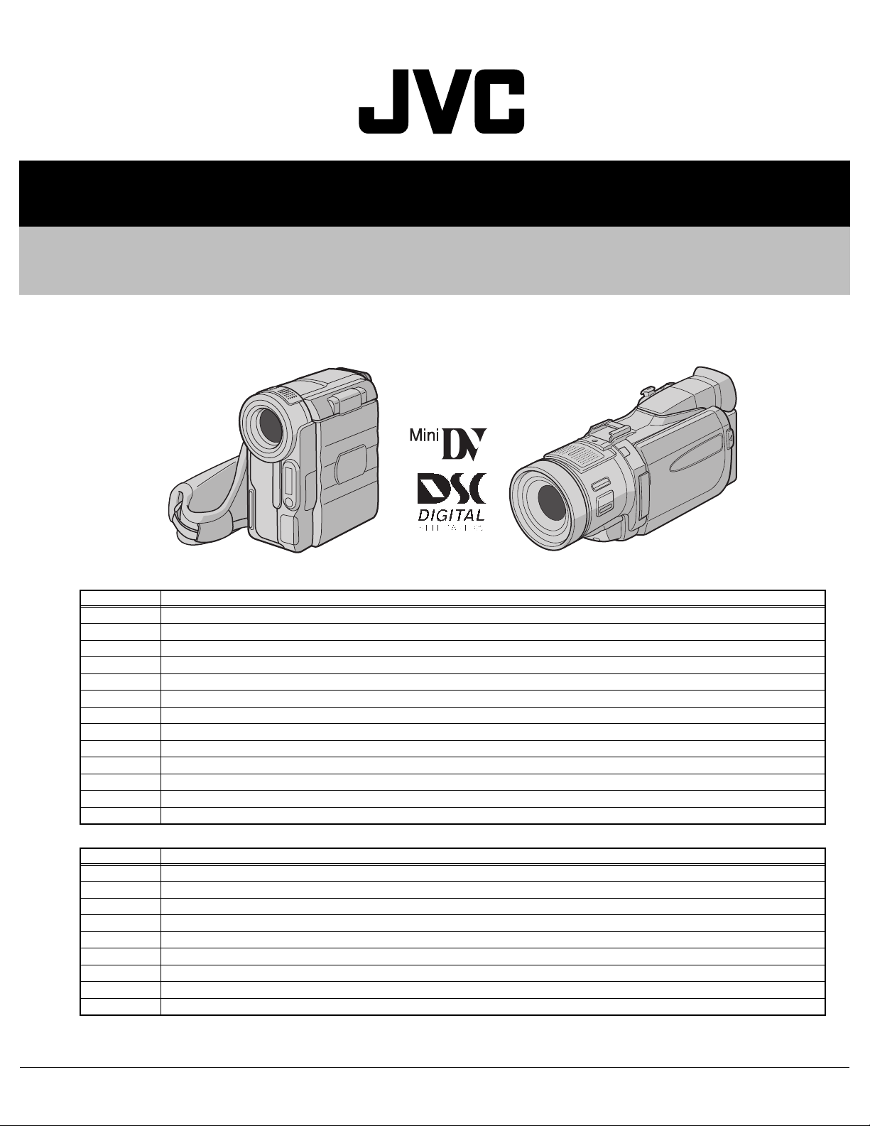
SERVICE MANUAL
DIGITAL VIDEO CAMERA
YF009200312
DISASSEMBLY
GR-DX Series
Manual No. Model name
86735 GR-DX25EX,GR-DX25EY,GR-DX25EZ,GR-DX25EK,GR-DX35EX,GR-DX35EY,GR-DX35EZ,GR-DX35EK
86740 GR-DX75EX,GR-DX75EY,GR-DX75EZ,GR-DX75EK,GR-DX95EX,GR-DX95EY,GR-DX95EZ,GR-DX95EK
86751 GR-DX100EX,GR-DX100EY,GR-DX100EZ,GR-DX100EK,GR-DX300EX,GR-DX300EY,GR-DX300EZ,GR-DX300EK
86752 GR-DX45EX,GR-DX45EY,GR-DX45EZ,GR-DX45EK,GR-DX55EX,GR-DX55EY,GR-DX55EZ,GR-DX55EK
86753 GR-DX75AA,GR-DX75AG,GR-DX75AH,GR-DX75AS,GR-DX76AG
86754 GR-DX35AC,GR-DX35AH
86755 GR-DX95AC,GR-DX95AH
86757 GR-DX75US,GR-DX95US
86762 GR-DX106AG
86763 GR-DX300AA,GR-DX300AG
86764 GR-DX300AC,GR-DX300AH
86765 GR-DX75KR,GR-DX95KR
86766 GR-DX300US
GR-DV Series
Manual No. Model name
86734 GR-DV500US,GR-DV800US,GR-DV801US,GR-DV900US
86736 GR-DV4000US
86756 GR-DV4000EX,GR-DV4000EY,GR-DV4000EZ,GR-DV4000EK
86758 GR-DV700EX,GR-DV700EY,GR-DV700EZ,GR-DV700EK
86759 GR-DV500KR,GR-DV700KR,GR-DV800KR,GR-DV900KR,GR-DV4000KR,GR-DV5000KR
86760 GR-DV400EX,GR-DV400EY, GR-DV500EX,GR-DV500EY,GR-DV500EZ
86767 GR-DV4000AG,GR-DV5000AA,GR-DV5000AG
86768 GR-DV500AA,GR-DV500AG,GR-DV500AS,GR-DV900AA,GR-DV900AG
86771 GR-DV700AH,GR-DV900AC,GR-DV4000AC,GR-DV5000AC
COPYRIGHT © 2003 VICTOR COMPANY OF JAPAN, LIMITED
No.YF009
2003/12
SECTION 1
DISASSEMBLY (GR-DX Series)
1.1 BEFORE ASSEMBLY AND DISASSEMBLY
1.1.1 Precautions
• Be sure to disconnect the power supply unit prior to mounting
and soldering of parts.
• Prior to removing a component part that needs to disconnect
its connector(s) and its screw(s), first disconnect the wire(s)
from the connector(s), and then remove the screw(s).
• When connecting/disconnecting wires, pay enough attention
not to damage the connectors.
• When inserting the flat wire to the connector, pay attention to
the direction of the flat wire.
• Be careful in removing the parts to which some spacer or
shield is attached for reinforcement or insulation.
• When replacing chip parts (especially IC parts), first remove
the solder completely to prevent peeling of the pattern.
• Tighten screws properly during the procedures. Unless
specified otherwise, tighten screws at a torque of 0.088N
·cm). However, 0.088N·m (0.9kgf·cm) is a value at the
(0.9kgf
time of production. At the time of service, perform the
procedure at a torque 10% less than 0.088N
·m (0.9kgf·cm).
(See "SERVICE NOTE" as for tightening torque.)
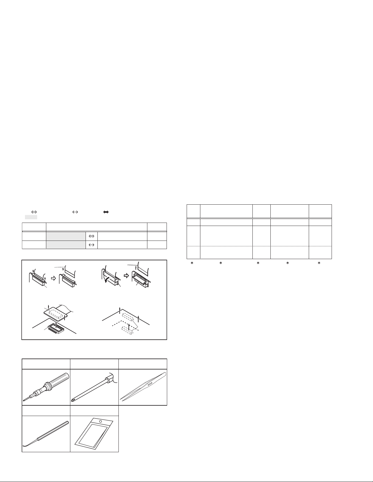
1.1.2 Destination of connectors
Two kinds of double-arrows in connection tables respectively
show kinds of connector/wires.
: Wire: Flat wire : Board to board (B-B)
: The connector of the side to remove
CONN. No. PIN No.CONNECTOR
CN2a
CN2b
MAIN CN101
MAIN CN103
MONI/ BW CN761
MIC CN762
1.1.3 Disconnection of connectors (Wires)
Wire
· Pull both ends of the connector in the arrow
direction, remove the lock and disconnect the flat
wire.
B-B Connector
B-B Connector
· Pull the both ends of the board in the direction of the arrow, and remove the B-B Connector.
FPC Connector
· Extend the locks in the direction of the arrow for
unlocking and then pull out the wire. After
removing the wire, immediately restore the locks
to their original positions because the locks are
apt to come off the connector.
Wire
FPC Connector
Lock
B-B Connector
Fig.3-1-1
1.1.4 Tools required for disassembly and assembly
Torque driver
YTU94088
Chip IC replacement jig
PTS40844-2
Bit
YTU94088-003
Cleaning cloth
KSMM-01
Tweezers
P-895
·m
40
2
• Torque driver
Be sure to use to fastening the mechanism and exterior parts
because those parts must strictly be controlled for tightening
torque.
• Bit
This bit is slightly longer than those set in conventional torque
drivers.
• Tweezers
To be used for removing and installing parts and wires.
• Chip IC replacement jig
To be used for replacement of IC.
• Cleaning cloth
Recommended cleaning cloth to wipe down the video heads,
mechanism (tape transport system), optical lens surface.
1.2 ASSEMBLY AND DISASSEMBLY OF MAIN PARTS
1.2.1 Assembly and disassembly
When reassembling, perform the step(s) in reverse order.
STEP
No.
[1]
[2]
[8]
PART
TOP COVER ASSEMBLY
UPPER ASSEMBLY
(Inc. VF ASSEMBLY,
SPEAKER/MONITOR)
VF ASSEMBLY
(∗1) Order of steps in Procedure
When reassembling, preform th e step(s) in the reverseorder.
These numbers are also used as the identification (location)
No. of parts Figures.
(∗2) Part to be removed or installed.
(∗3) Fig. No. showing Procedure or Part Location.
C = CABINET
(∗4) Identification of part to be removed, unhooked, unlocked,
released, unplugged, unclamped or unsoldered.
S = Screw
L = Lock, Release, Hook
SD = Solder
CN = Connector
[Example]
• 4 (S1a) = Remove four S1a screws.
• 3 (L1a) = Disengage three L1a hooks.
• 2 (SD1a) = Unsolder two SD1a points.
• CN1a = Remove a CN1a connector.
(∗5) Adjustment information for installation.
Fig.
No.
Fig.C1
Fig.C2-1
Fig.C2-2
POINT
S1,2(L1)
S2a,2(S2b),3(S2c)
2(S2d),S2e,S2c
L2,CN2a,b
2(S8),L8,CN8a
( 4) ( 5)( 2) ( 3)( 1)
NOTE
-
-
NOTE 8a
NOTE 8b
1-2 (No.YF009)
Fig.3-1-2

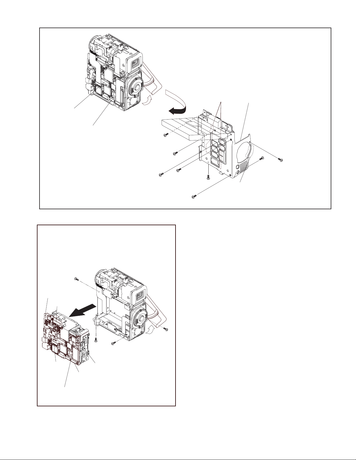
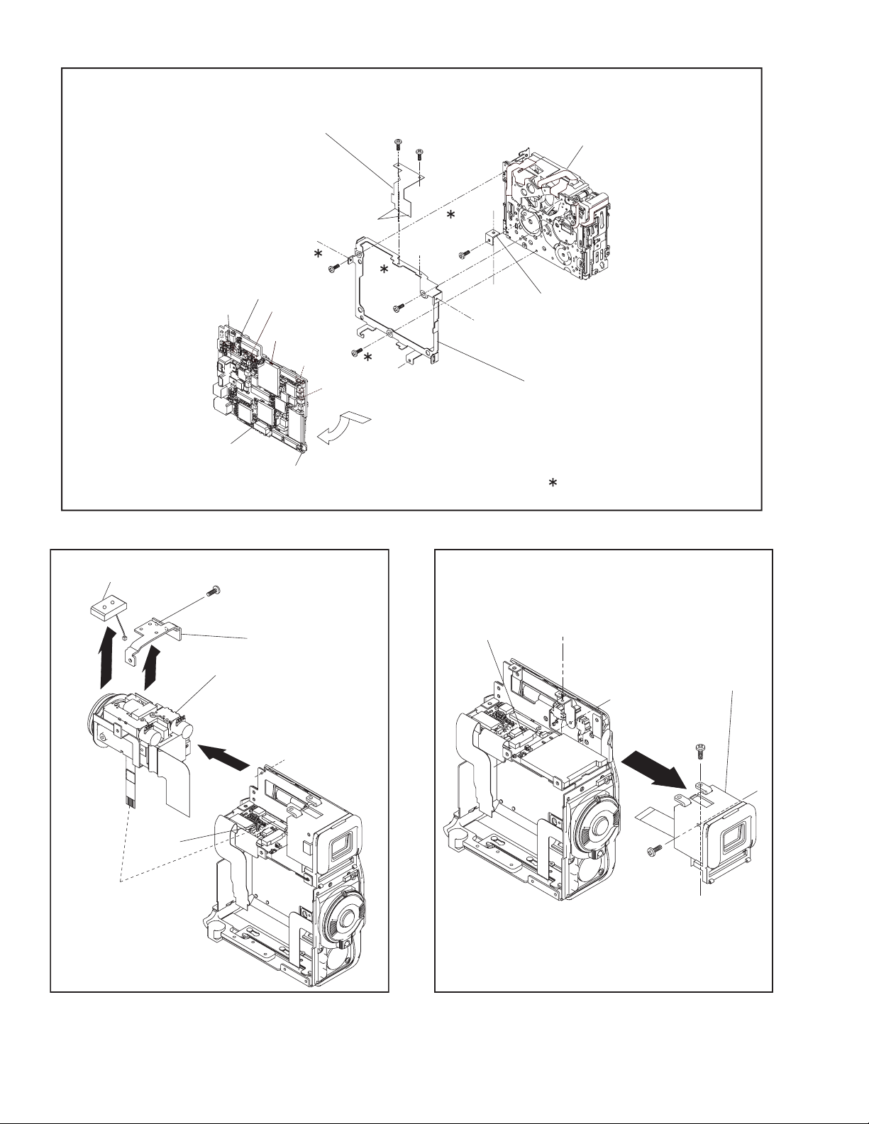
1.2.2 ASSEMBLY/DISASSEMBLY OF CABINET PARTS AND ELECTRICAL PARTS
zDisassembly procedure
Step
Parts Name
No.
[1]
COVER(TOP)
[2]
COVER(MIC)
[3]
FRONT COVER ASSY
[4]
COVER(DV)
[5]
UPPER ASSY
MAIN BOARD ASSY
[6]
/MECHANISM ASSY
/[7]
OP BLOCK ASSY
[8]
/MIC ASSY
/[9]
VF ASSY
[10]
Fig.
No.
(S1a),3(S1b),2(L1)
Fig.C1
L2
Fig.C2
2(S3a),(S3b),(S3c),(S3d),CN3,HOLDER(DV/USB)
Fig.C3
(S4a),(S4b)
Fig.C4
(S5a),(S5b),2(S5c),(S5d),(S5c),
(S5d),(S5e),CN5a,CN5b
CN6a,b,c,d,e,(S6a),3(S6b),2(S6c),
Fig.C5-1
Fig.C5-2
L6a,SHELD PLATE,L6b,CN6f,g,h,i,k,m
(S7a),3(S7b),BKT(PRE/REC),MECHA BKT ASSY
(S8),BKT(TOP),L8,CN8
Fig.C6
Fig.C7
CN10,2(S10)
Point Note
NOTE 3a:
Open the CASSETTE COVER, and remove the two screws
(No.7 and 8).
NOTE3b:
Take care not to cut the FPC and wire.
NOTE3c:
-
-
NOTE3a,b,c
-
NOTE5a,b
NOTE6a,b
-
NOTE8
NOTE10
zDestination of connectors
CN No.
CN3 MAIN CN115 STROBE CN6501 12
CN5a MAIN CN113 MONITOR CN7601 49/45
CN5b MAIN CN112 SUB OPE UNIT - 9
CN6a MAIN CN101 BATT.TERM. - 17
CN6b MAIN CN109 SD CN301 60
CN6c MAIN CN102 CCD - 20
CN6d MAIN CN111 CAMERA OPE UNIT - 11
CN6e MAIN CN114 MIC - 4
CN6f MAIN CN106 SENSOR - 16
CN6g MAIN CN110 HEAD - 8
CN6h MAIN CN103 LOADING MOTOR - 6
CN6j MAIN CN107
CN6k MAIN CN104 DRUM MOTOR - 11
CN6m MAIN CN108 CAPSTAN MOTOR - 18
CN8 SD CN302 OP BLOCK ASSY - 24
CN10 SD CN304 VF BW CN7001 18
Be careful about the HOLDER (DV/USB) because it is
removed together with the FRONT COVER ASSY.
NOTE5a:
Take care not to damage the part.
NOTE5b:
Take care not to cut the FPC.
NOTE6a:
Remove the MIC wire while removing the MAIN BOARD
ASSY.
NOTE6b:
Take care not to cut the FPC.
NOTE8:
Take care not to damage the LENS in OP BLOCK ASSY
and not to cut the FPC.
NOTE10:
Take care not to cut the FPC.
CONNECTOR
ROTARY ENCODER SW
Pin.
No.
- 6
(No.YF009)1-3
L2
3
(S1b)
1
(S1a)
L1
[1]
2
(S1b)
4
(S1b)
7
(S3b)
8
(S3c)
[2]
(S3a)
6
5
(S3a)
a
b
NOTE3b
Fig.C1
[3]
NOTE3b
CN3
a
b
CASETTE
COVER
[4]
10
(S4a)
11
(S4b)
Fig.C3
NOTE3a
1-4 (No.YF009)
HOLDER(DV/USB)
NOTE3c
9
(S3d)
Fig.C2
CN5a
CN5b
(S5e)
16
(S5d)
19
17
(S5c)
15
(S5c)
(S5c)
Fig.C4
14
18
(S5d)
NOTE5b
[5]
NOTE5a
13
(S5b)
12
(S5a)
(S6b)
NOTE6a
CN6e
CN6b
CN6a
[6]/[7]
23
c
CN6d
20
(S6a)
CN6c
Fig.C5-1
a
21
(S6b)
b
22
(S6b)
(No.YF009)1-5
SHIELD PLATE
CN6m
CN6f
CN6k
CN6g
C
27
(S7b)
L6a
24
(S6c)
28
(S7b)
25
(S6c)
d
e
26
(S7a)
[7]
d
e
b
BKT(PRE/REC)
[9]
[6]
NOTE6b
(S8)
a
[8]
30
BKT(TOP)
NOTE8
CN6j
L6b
a
CN6h
29
(S7b)
a
Fig.C5-2
MECHA BKT ASSY
CN10
a
: 0.068N.m(0.7kgf.cm)
NOTE10
[10]
b
31
(S10)
1-6 (No.YF009)
b
CN8
32
(S10)
a
Fig.C6 Fig.C7

1.2.3 SERVICE NOTE
[6]/[7]
cm)
.
m (0.7kgf
.
[8] [9]
[2]
[1] [3] [4] [5]
CABINET PARTS AND ELECTRICAL PARTS
Symbol No.
-
C1 C2 C3 C4 C5-1
1 2 3 4 - 5 6 7 8 9 1011121314151617181920212223
Place to stick screw
Removing order of screw
Screw tightening torque
Reference drawing (Fig.No.)
[6]/[7] [10]
CABINET PARTS AND ELECTRICAL PARTS
Symbol No.
-
24 25 26 27 28 29 - 30 31 32
Place to stick screw
Removing order of screw
C7C5-2 C6
cm) : 0.068N
.
m (0.9kgf
.
: 0.088N
1) * : Don't reuse the screw, because screw lock bond was applied to them.
2) Pay careful attention to tightening torque for each screw.
NOTE:
Screw tightening torque
Reference drawing (Fig.No.)
(No.YF009)1-7

SECTION 2
DISASSEMBLY (GR-DV Series)
2.1 BEFORE ASSEMBLY AND DISASSEMBLY
2.1.1 Precautions
• Be sure to disconnect the power supply unit prior to mounting
and soldering of parts.
• Prior to removing a component part that needs to disconnect
its connector(s) and its screw(s), first disconnect the wire(s)
from the connector(s), and then remove the screw(s).
• When connecting/disconnecting wires, pay enough attention
not to damage the connectors.
• When inserting the flat wire to the connector, pay attention to
the direction of the flat wire.
• Be careful in removing the parts to which some spacer or
shield is attached for reinforcement or insulation.
• When replacing chip parts (especially IC parts), first remove
the solder completely to prevent peeling of the pattern.
• Tighten screws properly during the procedures. Unless
specified otherwise, tighten screws at a torque of 0.078N
·cm). However, 0.078N·m (0.8kgf·cm) is a value at the
(0.8kgf
time of production. At the time of service, perform the
procedure at a torque 10% less than 0.078N
·m (0.8kgf·cm).
(See "SERVICE NOTE" as for tightening torque.)
2.1.2 Destination of connectors
Two kinds of double-arrows in connection tables respectively
show kinds of connector/wires.
: Wire: Flat wire : Board to board (B-B)
: The connector of the side to remove
CONN. No. PIN No.CONNECTOR
CN2a
CN2b
MAIN CN101
MAIN CN103
MONI/ BW CN761
MIC CN762
2.1.3 Disconnection of connectors (Wires)
Wire
· Pull both ends of the connector in the arrow
direction, remove the lock and disconnect the flat
wire.
B-B Connector
B-B Connector
· Pull the both ends of the board in the direction of the arrow, and remove the B-B Connector.
FPC Connector
· Extend the locks in the direction of the arrow for
unlocking and then pull out the wire. After
removing the wire, immediately restore the locks
to their original positions because the locks are
apt to come off the connector.
Wire
FPC Connector
Lock
B-B Connector
Fig.3-1-1
2.1.4 Tools required for disassembly and assembly
Torque driver
YTU94088
Chip IC replacement jig
PTS40844-2
Bit
YTU94088-003
Cleaning cloth
KSMM-01
Tweezers
P-895
·m
40
2
• Torque driver
Be sure to use to fastening the mechanism and exterior parts
because those parts must strictly be controlled for tightening
torque.
• Bit
This bit is slightly longer than those set in conventional torque
drivers.
• Tweezers
To be used for removing and installing parts and wires.
• Chip IC replacement jig
To be used for replacement of IC.
• Cleaning cloth
Recommended cleaning cloth to wipe down the video heads,
mechanism (tape transport system), optical lens surface.
2.2 ASSEMBLY AND DISASSEMBLY OF MAIN PARTS
2.2.1 Assembly and disassembly
When reassembling, perform the step(s) in reverse order.
STEP
No.
[1]
[2]
[8]
PART
TOP COVER ASSEMBLY
UPPER ASSEMBLY
(Inc. VF ASSEMBLY,
SPEAKER/MONITOR)
VF ASSEMBLY
(∗1) Order of steps in Procedure
When reassembling, preform th e step(s) in the reverseorder.
These numbers are also used as the identification (location)
No. of parts Figures.
(∗2) Part to be removed or installed.
(∗3) Fig. No. showing Procedure or Part Location.
C = CABINET
(∗4) Identification of part to be removed, unhooked, unlocked,
released, unplugged, unclamped or unsoldered.
S = Screw
L = Lock, Release, Hook
SD = Solder
CN = Connector
[Example]
• 4 (S1a) = Remove four S1a screws.
• 3 (L1a) = Disengage three L1a hooks.
• 2 (SD1a) = Unsolder two SD1a points.
• CN1a = Remove a CN1a connector.
(∗5) Adjustment information for installation.
Fig.
No.
Fig.C1
Fig.C2-1
Fig.C2-2
POINT
S1,2(L1)
S2a,2(S2b),3(S2c)
2(S2d),S2e,S2c
L2,CN2a,b
2(S8),L8,CN8a
( 4) ( 5)( 2) ( 3)( 1)
NOTE
-
-
NOTE 8a
NOTE 8b
1-8 (No.YF009)
Fig.3-1-2

2.2.2 ASSEMBLY/DISASSEMBLY OF CABINET PARTS AND ELECTRICAL PARTS
zDisassembly procedure
Step
No.
[10]
[11]
[12]
[13]
[14]
[15]
Parts Name
[1]
COVER(SHOE) ASSY
/[2]
UPPER ASSY
[3]
SHOE ASSY
[4]
FRONT ASSY
[5]
REAR ASSY
[6]
OP BLOCK ASSY
[7]
BASE
[8]
LOWER CASE ASSY
[9]
MAIN BOARD ASSY
PRE/MDA BOARD ASSY
MECHANISM ASSY
VF ASSY
MONITOR BOARD ASSY
COVER(UPPER)ASSY
MONITOR ASSY
Fig.No.
(S1a),(S1b)
Fig.C1
4(S2a),(S2b),(S2c),2(S2d),2(S2e),CN2
Fig.C2
CN3,S3,2(L3)
Fig.C3
CN4a,CN4b,(S4a),(S4b),(S4c),COVER(JACK)
Fig.C4
CN5,3(S5),COVER(DC)
Fig.C5
CN6a,CN6b,(S6a),(S6b),L6
Fig.C6
2(S7)
CN8a,CN8b,(S8a),3(S8b)
Fig.C7-1
(S9a),(S9b),L9,CN9a,CN9b
/Fig.C7-2
2(S10a),SHIELD COVER(PR),L10a
CN10a,b,c,d,e,f,(S10b),L10b
S(S11),BRACKET(MECHA)
CN12,(S12a),(S12b),L12
Fig.C8
Fig.C9
CN13a,CN13b,(S13a),6(S13b),KNOB(SLIDE)
2(S14)
Fig.C10-1
2(S15a),2(S15b)
Fig.C10-2
Point Note
NOTE2:
Open the MONITOR ASSY.
NOTE4a:
The screw no.16 is under the COVER (JACK).
NOTE4b:
CN4b is contained in only models with strobe function.
NOTE4c:
-
NOTE2
-
NOTE4a,b,c
-
-
-
-
-
-
-
-
NOTE13a,b,c
NOTE14
NOTE15
zDestination of connectors
CONN.
No.
CN2 MAIN CN106 MONITOR CN701 57
CN3 MAIN CN103 SHOE 16
CN4a MAIN CN111 FRONT CN501 30
CN4b MAIN CN109 STROBE CN6501 16
CN5 MAIN CN110 REG CN601 80
CN6a MAIN CN102 CCD - 20
CN6b MAIN CN104 OP BLOCK ASSY - 24
CN8a MAIN CN112 JACK CN201 12
CN8b MAIN CN114 ZOOM DIAL OPE - 16
CN9a MAIN CN108 PRE/MDA CN408 40
CN9b MAIN CN107 PRE/MDA CN401 40
CN10a PRE/MDA CN402 HEAD - 8
CN10b PRE/MDA CN404 DRUM MOTER - 11
CN10c PRE/MDA CN406 SENSOR - 16
CN10d PRE/MDA CN407
CN10e PRE/MDA CN403 LOADING MOTOR - 6
CN10f PRE/MDA CN405 CAPSTAN MOTOR - 18
CN12 MONITOR CN703 VF BL CN801 20/18
CN13a MONITOR CN702 BL
CN13b MONITOR CN704 SPEAKER - 2
After removing the FRONT ASSEMBLY, the OP BLOCK
ASSEMBLY is not covered with anything. Be careful not to
damage the OP BLOCK ASSEMBLY.
NOTE13a:
Take care not to lose the KNOB because the KNOB is
removed together with the MONITOR BOARD ASSY.
NOTE13b:
In attachment procedure, take care not to insert a wire.
NOTE13c:
Prior to removing the MONITOR BOARD ASSY, remove the
memory card.
NOTE14:
Prior to removing the COVER(UPPER)ASSY, close the
MONITOR.
NOTE15:
When removing the MONITOR ASSY, take care not to cut
or damage the FPC.
CONNECTOR
ROTARY ENCODER SW
PIN.
No.
- 6
CN601/CN605
38/21.21
(No.YF009)1-9
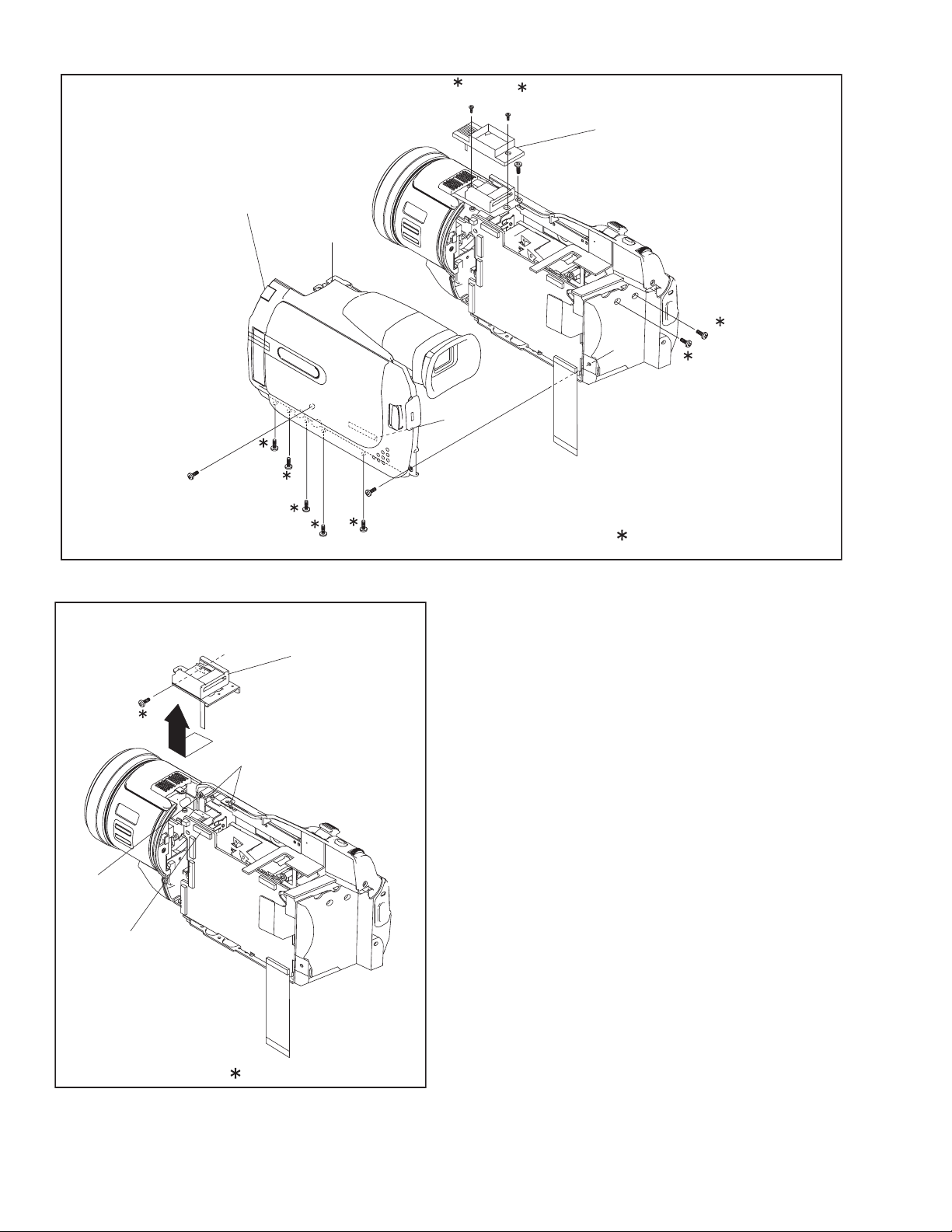
9
(S2d)
[2]
(S2b)
NOTE2
7
6
(S2a)
5
(S2a)
4
(S2a)
a
3
(S2a)
8
(S2c)
(S1a)
CN2
Fig.C1
1
2
(S1b)
[1]
10
(S2d)
a
11
(S2e)
12
(S2e)
: 0.098N.m(1.0kgf.cm)
b
CN3
13
(S3)
b
L3
[3]
: 0.098N.m(1.0kgf.cm)
Fig.C2
1-10 (No.YF009)

[4]
COVER(JACK)
15
(S4b)
16
(S4c)
NOTE4a
a
g
a
CN4b
NOTE4b
14
(S4a)
NOTE4c
CN4a
Fig.C3
[5]
CN5
a
Fig.C4
a
19
(S5)
17
(S5)
18
(S5)
COVER(DC)
(No.YF009)1-11

21
(S6b)
[6]
CN6b
20
(S6a)
CN6a
d
L6
[7]
d
a
b
22
(S7)
23
(S7)
Fig.C5 Fig.C6
a
b
27
(S8b)
[8]
26
(S8b)
c
CN8a
d
e
c
d
CN8b
a
b
e
a
b
25
(S8b)
24
(S8a)
[9]/[10]/[11]
Fig.C7-1
1-12 (No.YF009)

28
(S9a)
SHIELD COVER(PR)
30
(S10a)
32
(S10b)
CN10c
CN9a
31
(S10a)
CN10f
c
L10a
CN10b
a
a
b
33
(S11)
CN10a
b
34
(S11)
CN10e
L10b
35
(S11)
[11]
BRACKET(MECHA)
29
(S9b)
d
[10]
L9
c
d
[9]
CN10d
CN9b
: 0.068N.m(0.7kgf.cm)
Fig.C7-2
36
(S12a)
CN12
L12
37
(S12b)
[12]
Fig.C8
(No.YF009)1-13

39
(S13b)
40
(S13b)
38
(S13a)
44
(S13b)
(S13b)
42
(S13b)
43
CN13a
Fig.C9
KNOB(SLIDE)
NOTE13a
41
(S13b)
CN13b
[13]
NOTE13b NOTE13c
NOTE14
[14]
1-14 (No.YF009)
a
45
(S14)
a
b
Fig.C10-1
b
46
(S14)

49
(S15b)
50
(S15b)
[15]
47
(S15a)
48
(S15a)
a
a
NOTE15
b
b
: 0.198N.m(2.0kgf.cm)
Fig.C10-2
(No.YF009)1-15

2.2.3 SERVICE NOTE
cm)
.
[8][1] [2]
m (2.0kgf
.
C6 C7-1
[6] [7][5]
[4]
[3]
C4 C5
C3
C2
C1
[13]
[12] [14] [15]
C10-1 C10-2C7-2 C9
C8
cm) : 0.198N
.
m (1.0kgf
.
cm) : 0.098N
.
m (0.7kgf
.
cm) : 0.068N
.
1-16 (No.YF009)
[10] [11]
CABINET PARTS AND ELECTRICAL PARTS
1 2 3 4 5 6 7 8 9 101112131415161718192021222324252627
Symbol No.
Place to stick screw
Removing order of screw
Screw tightening torque
Reference drawing (Fig.No.)
[9]
CABINET PARTS AND ELECTRICAL PARTS
28 29 30 31 32 33 34 35 36 37 38 39 40 41 42 43 44 45 46 47 48 49 50
Symbol No.
Place to stick screw
Removing order of screw
m (0.8kgf
.
: 0.078N
1) * : Don't reuse the screw, because screw lock bond was applied to them.
2) Pay careful attention to tightening torque for each screw.
NOTE:
Screw tightening torque
Reference drawing (Fig.No.)

VICTOR COMPANY OF JAPAN, LIMITED
AV & MULTIMEDIA COMPANY CAMCORDER CATEGORY 12, 3-chome, Moriya-cho, kanagawa-ku, Yokohama, kanagawa-prefecture, 221-8528, Japan
(No.YF009)
Printed in Japan
WPC
 Loading...