

Page 1
SERVICE MANUAL
DIGITAL VIDEO CAMERA
VICTOR COMPANY OF JAPAN, LIMITED
VIDEO DIVISION
S40894
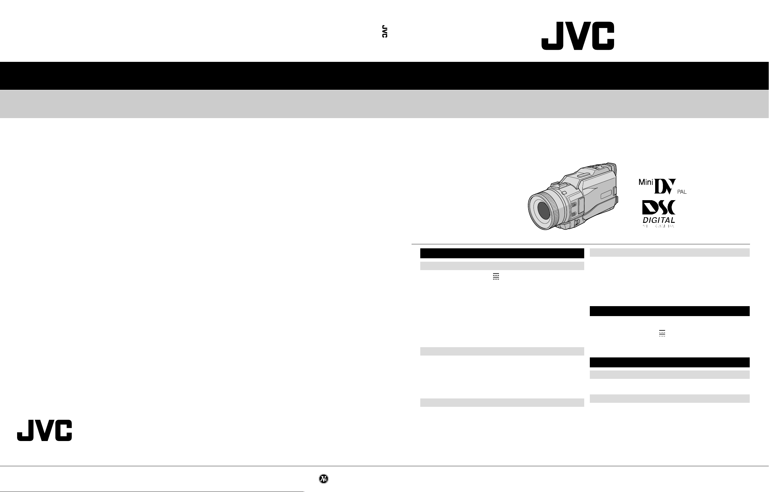
GR-DV3000A/EA/ED/EG/EK/SH
GR-DV3000A/EA/ED/EG/EK/SH
SPECIFICATIONS
No. 86666
Power supply : DC 6.3 V (Using AC Power Adapter/Charger)
Power consumption
LCD monitor off, viewfinder on : Approx. 4.3 W
LCD monitor on, viewfinder off : Approx. 5.4 W
Dimensions (W x H x D) : 76 mm x 90 mm x 194 mm
Weight : Approx. 660 g (without cassette, memory card and battery)
Operating temperature : 0°C to 40°C
Operating humidity : 35% to 80%
Storage temperature : –20°C to 50°C
Pickup : 1/3.6" CCD
Lens : F 1.2, f = 4.5 mm to 45 mm, 10:1 power zoom lens
Filter diameter : ø52 mm
LCD monitor : 3.5" diagonally measured, LCD panel/TFT active matrix system
Viewfinder : Electronic viewfinder with 0.44" colour LCD
Speaker : Monaural
Format : DV format (SD mode)
Signal format : PAL standard
Recording/Playback format : Video: Digital component recording
Cassette : Mini DV cassette
Tape speed : SP: 18.8 mm/s
Maximum recording time : SP: 80 min.
(using 80 min. cassette) LP: 120 min.
Storage media : SD Memory Card/MultiMediaCard
Compression system : Still image : JPEG (compatible)
File size : Still image :
Picture quality : 2 modes (FINE/STANDARD)
Approximate number of storable images
(with the provided memory card [8 MB])
FINE : 32 (640 x 480 pixels), 14 (1024 x 768 pixels),
STANDARD : 110 (640 x 480 pixels), 46 (1024 x 768 pixels),
For other memory cards, 墌 pg. 17.
DC 7.2 V (Using battery pack)
(with the LCD monitor closed and the viewfinder pushed back in,
without the lens hood)
Approx. 740 g (incl. cassette, memory card and battery)
Digital Video Camera
: Audio: PCM digital recording, 32 kHz 4-channel (12-bit),
48 kHz 2-channel (16-bit)
LP: 12.5 mm/s
Digital Still Camera Function
Moving image : MPEG4 (compatible)
Moving image : 2 modes (240 x 176 pixels, 160 x 120 pixels)
9 (1280 x 960 pixels), 6 (1600 x 1200 pixels)
30 (1280 x 960 pixels), 20 (1600 x 1200 pixels)
(The specifications shown pertain specifically to the model GR-DV3000EG/EK)
Camcorder
General
AV
Video output : 1 V (p-p), 75 Ω, analogue
Video input : 0.5 V (p-p) – 2.0 V (p-p), 75 Ω, analogue
Audio output : 300 mV (rms), 1 kΩ, analogue, stereo
Audio input : 300 mV (rms), 50 kΩ, analogue, stereo
DV
Input/output : 4-pin, IEEE 1394 compliant
PHONE
Headphone output : ø3.5 mm, stereo
PRINTER : For an optional video printer equipped with a PRINT DATA
Connectors
connector
AC Power Adapter/Charger AA-V40EG or AA-V40EK
Power requirement : AC 110 V to 240 V`, 50 Hz/60 Hz
Power consumption : 23 W
Output
Charge : DC 7.2 V , 1.2 A
VTR : DC 6.3 V , 1.8 A
Dimensions (W x H x D) : 68 mm x 38 mm x 110 mm
Weight
AA-V40EG : Approx. 260 g
AA-V40EK : Approx. 340 g
Jack Box CU-V504U
General
Dimensions (W x H x D) : 37.5 mm x 18.5 mm x 55 mm
Weight : Approx. 30 g
Connectors
USB : TYPE B
S-VIDEO
4 modes (1600 x 1200 pixels, 1280 x 960 pixels,
1024 x 768 pixels, 640 x 480 pixels)
Output : Y: 1 V (p-p), 75 Ω, analogue
Input : Y: 0.8 V (p-p) – 1.2 V (p-p), 75 Ω, analogue
EDIT : ø3.5 mm, 2-pole
Specifications shown are for SP mode unless otherwise indicated. E & O.E. Design and
specifications subject to change without notice.
C: 0.29 V (p-p), 75 Ω, analogue
C: 0.2 V (p-p) – 0.4 V (p-p), 75 Ω, analogue
Printed in Japan
This service manual is printed on 100% recycled paper.
COPYRIGHT © 2002 VICTOR COMPANY OF JAPAN, LTD.
No. 86666
January 2002
Page 2

TABLE OF CONTENTS
Section Title Page Section Title Page
Important Safety Precautions
INSTRUCTIONS
1. DISASSEMBLY
1.1 BEFORE ASSEMBLY AND DISASSEMBLY ......................... 1-1
1.1.1 Precautions ..................................................................... 1-1
1.1.2 Assembly and disassembly ............................................ 1-1
1.1.3 Destination of connectors ............................................... 1-1
1.1.4 Disconnection of Connectors (Wires) ............................. 1-1
1.2 JIGS AND TOOLS REQUIRED FOR DISASSEMBLY,
ASSEMBLY AND ADJUSTMENT ......................................... 1-2
1.2.1 Tools required for adjustments ........................................ 1-2
1.3 DISASSEMBLY/ASSEMBLY OF CABINET PARTS AND
BOARD ASSEMBLY ............................................................. 1-2
1.3.1 Disassembly flow chart ................................................... 1-2
1.3.2 Disassembly method ...................................................... 1-3
1.4 DISASSEMBLY OF THE 4 OP BLOCK AND
CCD BOARD ASSEMBLIES ................................................. 1-8
1.4.1 Precautions ..................................................................... 1-8
1.4.2 How to remove................................................................ 1-8
1.4.3 How to install .................................................................. 1-8
1.4.4 Replacement of Service Repair Parts ............................ 1-8
1.5 7 E.VF(COLOR) ................................................................... 1-9
1.5.1 Disassembly/Assembly of the 7 E.VF(COLOR)............. 1-9
1.6
DISASSEMBLY/ASSEMBLY OF THE @ MONITOR ASSEMBLY
1.6.1 @ Monitor Assembly and Hinge Assembly ................... 1-10
1.7 MANUAL EJECTION OF THE CASSETTE TAPE............... 1-11
1.8 EMERGENCY DISPLAY ..................................................... 1-12
1.9 SERVICE NOTE.................................................................. 1-13
2. MECHANISM ADJUSTMENT
2.1
PRELIMINARY REMARKS ON ADJUSTMENT AND REPAIR ..
2.1.1 Precautions ..................................................................... 2-1
2.1.2 Notes on procedure for disassemby/assembly ............... 2-1
2.2 JIGS AND TOOLS REQUIRED FOR DISASSEMBLY,
ASSEMBLY AND ADJUSTMENT ......................................... 2-2
2.2.1 Tools required for adjustments ........................................ 2-2
2.3 DISASSEMBLY/ASSEMBLY OF MECHANISM ASSEMBLY 2-3
2.3.1 General statement .......................................................... 2-3
2.3.2 Explanation of mechanism mode ................................... 2-3
2.3.3 Mechanism timing chart .................................................. 2-4
2.4 DISASSEMBLING PROCEDURE TABLE ............................. 2-5
2.4.1 Disassembly/assembly ................................................... 2-7
2.4.2 List of procedures for disassembly ............................... 2-13
2.5
CHECKUP AND ADJUSTMENT OF MECHANISM PHASE ..
2.6 MECHANISM ADJUSTMENTS .......................................... 2-15
2.6.1 Adjustment of the slide guide plate ............................... 2-15
2.6.2
Adjustment of the Tension Arm and Pad Arm Assemblies
2.6.3 Adjustment of the Slide Lever 2 .................................... 2-16
2.7 SERVICE NOTE.................................................................. 2-17
2.8 JIG CONNECTOR CABLE CONNECTION ........................ 2-19
2.8.1 Tape pattern check ....................................................... 2-20
3. ELECTRICAL ADJUSTMENT
3.1 PRECAUTION ....................................................................... 3-1
3.2 SETUP .................................................................................. 3-2
3.3 MONITOR ADJUSTMENT .................................................... 3-3
3.3.1 PLL (MONI) .................................................................... 3-3
3.4 ELECTRONIC VIEWFINDER (E.VF) ADJUSTMENT ........... 3-3
3.4.1 PLL (VF) ......................................................................... 3-3
1-10
2-1
2-14
2-16
4. CHARTS AND DIAGRAMS
NOTES OF SCHEMATIC DIAGRAM .......................................... 4-1
CIRCUIT BOARD NOTES ........................................................... 4-2
4.1 BOARD INTERCONNECTIONS ........................................... 4-3
4.2
MAIN IF SCHEMATIC DIAGRAM ............................................... 4-5
4.3 SYSCON-CPU SCHEMATIC DIAGRAM .................................... 4-7
4.4 MSD-CPU SCHEMATIC DIAGRAM ............................................ 4-9
4.5 AUDIO AD/DA SCHEMATIC DIAGRAM ................................... 4-11
4.6 MAIN AUDIO SCHEMATIC DIAGRAM ..................................... 4-13
4.7 DVMAIN SCHEMATIC DIAGRAM ............................................ 4-15
4.8 VIDEO I/O SCHEMATIC DIAGRAM ......................................... 4-17
4.9 CDS/AD SCHEMATIC DIAGRAM ............................................. 4-19
4.10 DSP SCHEMATIC DIAGRAM ................................................ 4-21
4.11 OP DRIVE SCHEMATIC DIAGRAM ...................................... 4-23
4.12 TG/VDR SCHEMATIC DIAGRAM .......................................... 4-25
4.13 DSC SCHEMATIC DIAGRAM ................................................ 4-27
4.14 DSC IF AND SD SCHEMATIC DIAGRAMS ........................... 4-29
4.15 USB SCHEMATIC DIAGRAM ................................................ 4-31
4.16 MDA SCHEMATIC DIAGRAM ................................................ 4-33
4.17 PRE/REC SCHEMATIC DIAGRAM ........................................ 4-35
4.18 JUNCTION SCHEMATIC DIAGRAM ..................................... 4-37
4.19 REG SCHEMATIC DIAGRAM ................................................ 4-39
4.20 MONITOR SCHEMATIC DIAGRAM ....................................... 4-41
4.21 JACK SCHEMATIC DIAGRAM .............................................. 4-43
4.22 EJECT, DECK OPE. AND CCD SCHEMATIC DIAGRAMS .. 4-45
4.23
FE SW, FRONT, ZOOM UNIT, POWER OPE. UNIT, FOCUS UNIT
AND SW FPC UNIT SCHEMATIC DIAGRAMS ................................
4.24 VF BL SCHEMATIC DIAGRAM .............................................. 4-49
4.25 MAIN CIRCUIT BOARD [GR-DV3000EG] ............................. 4-51
4.26 MAIN CIRCUIT BOARD [GR-DV3000EK/A/EA/ED/SH] ......... 4-57
4.27 DSC CIRCUIT BOARD ........................................................... 4-63
4.28 PRE/MDA CIRCUIT BOARD .................................................. 4-65
4.29 JUNCTION AND JACK CIRCUIT BOARDS ........................... 4-67
4.30 REG CIRCUIT BOARD [GR-DV3000EG] ............................... 4-69
4.31 REG CIRCUIT BOARD [GR-DV3000EK/A/EA/ED/SH] .......... 4-71
4.32 MONITOR CIRCUIT BOARD ................................................. 4-73
4.33 EJECT AND DECK OPE. CIRCUIT BOARDS ....................... 4-75
4.34 CCD CIRCUIT BOARD .......................................................... 4-77
4.35 FE SW AND FRONT CIRCUIT BOARDS .............................. 4-78
4.36 VF BL CIRCUIT BOARD ........................................................ 4-79
4.37 VOLTAGE CHARTS ............................................................... 4-80
4.38 POWER SYSTEM BLOCK DIAGRAM ................................... 4-85
4.39 VIDEO SYSTEM BLOCK DIAGRAM ...................................... 4-87
4.40 REGULATOR SYSTEM BLOCK DIAGRAM .......................... 4-91
5. PARTS LIST
5.1 PACKING AND ACCESSORY ASSEMBLY <M1> ............... 5-1
5.2 FINAL ASSEMBLY <M2> ..................................................... 5-3
5.3 MECHANISM ASSEMBLY <M3> ......................................... 5-6
5.4 ELECTRONIC VIEWFINDER ASSEMBLY <M4> ................ 5-8
5.5 MONITOR ASSEMBLY <M5> .............................................. 5-9
5.6 ELECTRICAL PARTS LIST ................................................. 5-10
MAIN BOARD ASSEMBLY <01> ............................................. 5-10
DSC BOARD ASSEMBLY <02> .............................................. 5-17
PRE/MDA BOARD ASSEMBLY <03> ..................................... 5-18
JUNCTION BOARD ASSEMBLY <04> ................................... 5-19
REG BOARD ASSEMBLY <05> .............................................. 5-19
MONITOR BOARD ASSEMBLY <06> ..................................... 5-20
JACK BOARD ASSEMBLY <07> ............................................. 5-22
EJECT BOARD ASSEMBLY <08> .......................................... 5-22
DECK OPE. BOARD ASSEMBLY <09> .................................. 5-22
CCD BOARD ASSEMBLY <10> .............................................. 5-23
FE SW BOARD ASSEMBLY <11> .......................................... 5-23
FRONT BOARD ASSEMBLY <12> ......................................... 5-23
VF BL BOARD ASSEMBLY <13> ............................................ 5-23
4-47
The following table lists the differing points between Models GR-DV3000EG, GR-DV3000EK, GR-DV3000EA, GR-DV3000A,
GR-DV3000SH and GR-DV3000ED in this serise.
GR-DV3000EG GR-DV3000EK GR-DV3000EA GR-DV3000A GR-DV3000SH GR-DV3000ED
AC ADAPTER CHARGER AA-V40EG AA-V40EK AA-V40EA AA-V40A AA-V40SH AA-V40ED
PERI-RCA ADAPTER USED USED NOT USED NOT USED NOT USED NOT USED
CONVERSION PLUG NOT USED NOT USED NOT USED USED NOT USED NOT USED
Page 3
Important Safety Precautions
Prior to shipment from the factory, JVC products are strictly inspected to conform with the recognized product safety and electrical codes of the
countries in which they are to be sold. However, in order to maintain such compliance, it is equally important to implement the following precautions
when a set is being serviced.
Precautions during Servicing
•
1. Locations requiring special caution are denoted by labels and inscriptions on the cabinet, chassis and certain parts of the product.
When performing service, be sure to read and comply with these
and other cautionary notices appearing in the operation and service manuals.
2. Parts identified by the ! symbol and shaded ( ) parts are
critical for safety.
Replace only with specified part numbers.
Note: Parts in this category also include those specified to com-
ply with X-ray emission standards for products using
cathode ray tubes and those specified for compliance
with various regulations regarding spurious radiation
emission.
3. Fuse replacement caution notice.
Caution for continued protection against fire hazard.
Replace only with same type and rated fuse(s) as specified.
4. Use specified internal wiring. Note especially:
1) Wires covered with PVC tubing
2) Double insulated wires
3) High voltage leads
5. Use specified insulating materials for hazardous live parts. Note
especially:
1) Insulation Tape 3) Spacers 5) Barrier
2) PVC tubing 4) Insulation sheets for transistors
6. When replacing AC primary side components (transformers, power
cords, noise blocking capacitors, etc.) wrap ends of wires securely
about the terminals before soldering.
12. Crimp type wire connector
In such cases as when replacing the power transformer in sets
where the connections between the power cord and power transformer primary lead wires are performed using crimp type connectors, if replacing the connectors is unavoidable, in order to prevent
safety hazards, perform carefully and precisely according to the
following steps.
1) Connector part number : E03830-001
2) Required tool : Connector crimping tool of the proper type which
will not damage insulated parts.
3) Replacement procedure
(1) Remove the old connector by cutting the wires at a point
close to the connector.
Important : Do not reuse a connector (discard it).
cut close to connector
Fig.3
(2) Strip about 15 mm of the insulation from the ends of the
wires. If the wires are stranded, twist the strands to avoid
frayed conductors.
15 mm
Fig.1
7. Observe that wires do not contact heat producing parts (heatsinks,
oxide metal film resistors, fusible resistors, etc.)
8. Check that replaced wires do not contact sharp edged or pointed
parts.
9. When a power cord has been replaced, check that 10-15 kg of
force in any direction will not loosen it.
Power cord
Fig.2
10. Also check areas surrounding repaired locations.
11. Products using cathode ray tubes (CRTs)
In regard to such products, the cathode ray tubes themselves, the
high voltage circuits, and related circuits are specified for compliance with recognized codes pertaining to X-ray emission.
Consequently, when servicing these products, replace the cathode ray tubes and other parts with only the specified parts. Under
no circumstances attempt to modify these circuits.
Unauthorized modification can increase the high voltage value and
cause X-ray emission from the cathode ray tube.
Fig.4
(3) Align the lengths of the wires to be connected. Insert the
wires fully into the connector.
Metal sleeve
Connector
Fig.5
(4) As shown in Fig.6, use the crimping tool to crimp the metal
sleeve at the center position. Be sure to crimp fully to the
complete closure of the tool.
1
.2
5
2
.0
5
.5
Fig.6
(5) Check the four points noted in Fig.7.
Not easily pulled free
Wire insulation recessed
more than 4 mm
Fig.7
Crimping tool
Crimped at approx. center
of metal sleeve
Conductors extended
I
S40888-01
Page 4
Safety Check after Servicing
•
Examine the area surrounding the repaired location for damage or deterioration. Observe that screws, parts and wires have been returned
to original positions, Afterwards, perform the following tests and confirm the specified values in order to verify compliance with safety
standards.
1. Insulation resistance test
Confirm the specified insulation resistance or greater between power cord plug prongs and externally exposed parts of the set (RF terminals, antenna terminals, video and audio input and output
terminals, microphone jacks, earphone jacks, etc.). See table 1 below.
2. Dielectric strength test
Confirm specified dielectric strength or greater between power cord plug prongs and exposed accessible parts of the set (RF terminals, antenna terminals, video and audio input and output terminals,
microphone jacks, earphone jacks, etc.). See table 1 below.
3. Clearance distance
When replacing primary circuit components, confirm specified clearance distance (d), (d’) between soldered terminals, and between terminals and surrounding metallic parts. See table 1
below.
Fig. 8
4. Leakage current test
Confirm specified or lower leakage current between earth ground/power cord plug prongs and
externally exposed accessible parts (RF terminals, antenna terminals, video and audio input and
output terminals, microphone jacks, earphone jacks, etc.).
Measuring Method : (Power ON)
Insert load Z between earth ground/power cord plug prongs and externally exposed accessible
parts. Use an AC voltmeter to measure across both terminals of load Z. See figure 9 and following
table 2.
Externally
exposed
accessible part
Fig. 9
Z
V
ab
A
c
5. Grounding (Class 1 model only)
Confirm specified or lower grounding impedance between earth pin in AC inlet and externally exposed accessible parts (Video in, Video out,
Audio in, Audio out or Fixing screw etc.).
Measuring Method:
Connect milli ohm meter between earth pin in AC inlet and exposed accessible parts. See figure 10 and grounding specifications.
Fig. 10
Table 1 Specifications for each region
Table 2 Leakage current specifications for each region
Note: These tables are unofficial and for reference only. Be sure to confirm the precise values for your particular country and locality.
II
S40888-01
Page 5

SECTION 1
DISASSEMBLY
1.1 BEFORE ASSEMBLY AND DISASSEMBLY
1.1.1 Precautions
1. Be sure to remove the power supply unit prior to mounting and soldering of parts.
2. When removing a component part that needs to disconnect the connector and to remove the screw for removing itself, first disconnect the connecting wire from the
connector and then remove the screw beforehand.
3. When connecting and disconnecting the connectors, be
careful not to damage the wire.
4. Carefully remove and handle the part to which some
spacer or shield is attached for reinforcement or insulation.
5. When replacing chip parts (especially IC parts), desolder
completely first (to prevent peeling of the pattern).
6. Tighten screws properly during the procedures.
Unless specified otherwise, tighten screws at a torque
of 0.078N
•
m(0.8kgf•cm).
1.1.2 Assembly and disassembly
STEP
No.
1
2
PART
ZOOM OPE UNIT Fig.1-3-1 3(S1),(L1a),5(L1b),CN1a-
FRONT COVER Fig.1-3-2a CN2a,CN2b,2(S2a),(S2b), NOTE2a
ASSY (S2c),(S2d),2(S2e),CN2c NOTE2b
Fig.No.
POINT NOTE
NOTE2c
NOTE2d
1.1.4 Disconnection of Connectors (Wires)
Connector
Pull both ends of the connector in the arrow direction, remove the lock and disconnect the flat wire.
Flat wire
Connector
Fig. 1-1-1 Connector 1
Extend the locks in the direction of the arrow for unlocking
and then pull out the wire. After removing the wire, immediately restore the locks to their original positions because
the locks are apt to come off the connector.
Flat wire
(1) (2) (3) (4) (5)
(1) Indicate the disassembly steps. When assembling, per-
form in the reverse order of these steps. This number
corresponds to the number in the disassembly diagram.
(2) Indicates the name of disassembly/assembly parts.
(3) Indicates the number in the disassembly diagram.
(4) Indicates parts and points such as screws, washers,
springs which must be removed during disassembly/
assembly.
Symbol Name, Point
S Screw
L Lock, Pawl, Hook
SD Soldering
夡(Others) Connector, Cover, Bracket, etc.
(Example)
• 2 (S1) : Remove the two screws (S1) for removing
the part 1.
• CN 1a : Disconnect the connector 1a.
•SD1 : Unsolder at the point SD1.
(5) Precautions on disassembly/assembly.
1.1.3 Destination of connectors
Note:
Three kinds of double-arrows in connection tables respectively show kinds of connector/wires.
↔ : Wire
⇔ : Flat wire
: Board to Board connector
[Example]
Note:
Remove the parts marked in .
CONN.
No.
1a JUNCTION CN1102 ⇔ ZOOM OPE – 8
CONNECTOR
Pin No.
Connector
Fig. 1-1-2 Connector 2
B-B connector
Pull the board by both the sides in the direction of the arrow for disconnecting the B-B connector.
Connector
Connector
Fig. 1-1-3 Connector 3
Connector
Fig. 1-1-4 Connector 4
1-1
Page 6
1.2 JIGS AND TOOLS REQUIRED FOR DISASSEMBLY,
2
1
3
4
5
6
7
8
9
0
!
ASSEMBLY AND ADJUSTMENT
1.2.1 Tools required for adjustments
1
Torque driver
YTU94088
2
Bit
YTU94088-003
1.3 DISASSEMBLY/ASSEMBLY OF CABINET PARTS
AND BOARD ASSEMBLY
1.3.1 Disassembly flow chart
This flowchart indicates the disassembly step for the cabinet parts and board assembly in order to gain access to
item(s) to be serviced. When reassembling, perform the
step(s) in reverse order.
ZOOM OPE UNIT
3
5
1. Torque driver
2. Bit
3. Tweezers
4. Chip IC replacement jig
5. Cleaning cloth
Tweezers
P-895
Cleaning cloth
KSMM-01
Be sure to use to fastening the mechanism and exterior
parts because those parts must strictly be controlled for
tightening torque.
This bit is slightly longer than those set in conventional
torque drivers.
To be used for removing and installing parts and wires.
To be used for adjustment of the camera system.
Recommended cleaning cloth to wipe down the video
heads, mechanism (tape transport system), optical lens
surface.
4
Table 1-2-1
Chip IC replacement jig
PTS40844-2
FRONT COVER ASSY
(Inc. FE SW BOARD ASSY,
FRONT BOARD ASSY,
JUNCTION BOARD ASSY,
SHOE ASSY, SW FPC UNIT,
FOCUS UNIT, MICROPHONE)
UPPER CASE ASSY
(Inc.
MONITOR ASSY)
@
OP BLOCK ASSY
DSC BOARD ASSY
REAR COVER ASSY
E. VF ASSY
LOWER CASE ASSY
MAIN BOARD ASSY
/
PRE/MDA BOARD ASSY,
MECHANISM ASSY
Table 1-3-1
1-2
Page 7
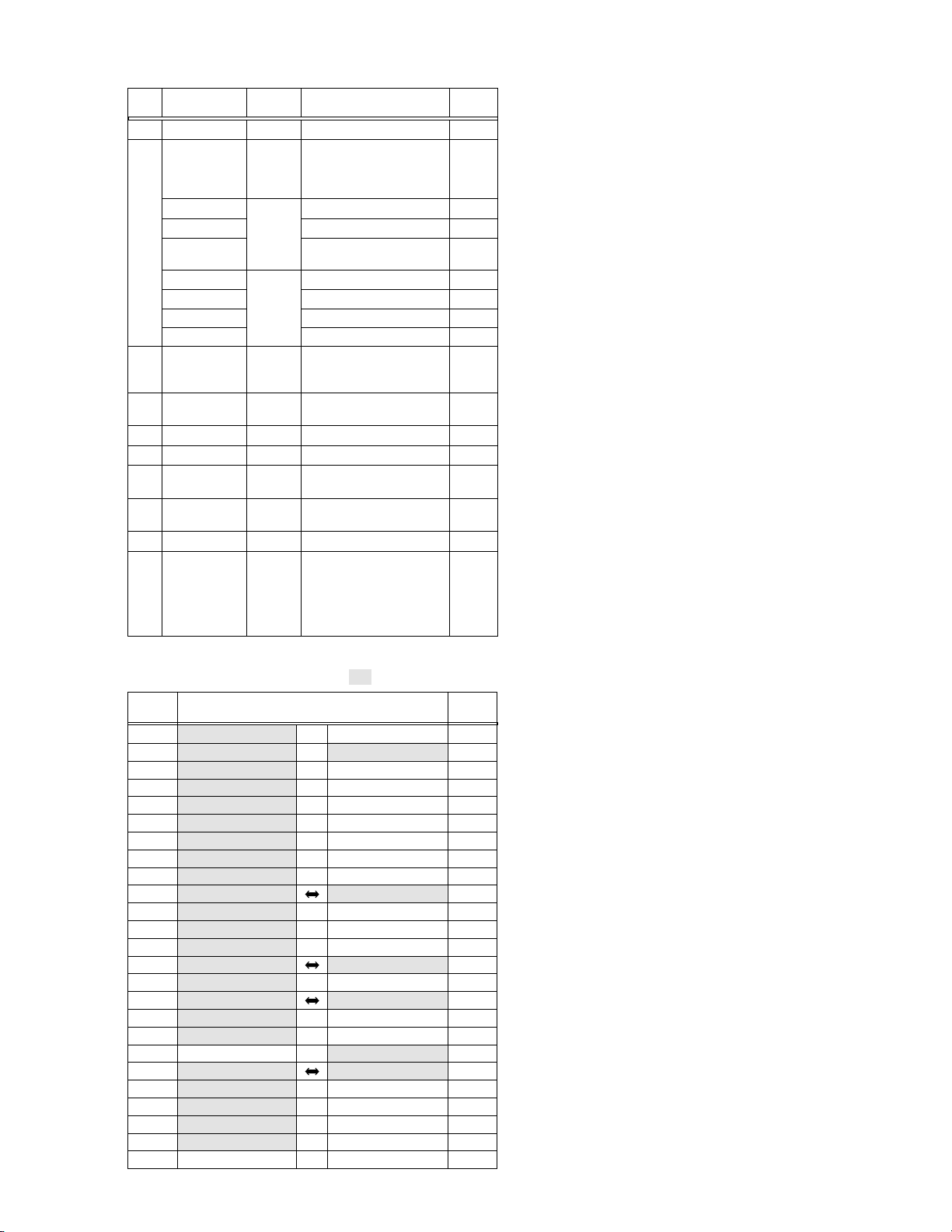
1.3.2 Disassembly method
STEP
No.
1
2
3
PART
ZOOM OPE UNIT Fig.1-3-1 3(S1),(L1a),5(L1b),CN1a-
FRONT COVER Fig.1-3-2a CN2a,CN2b,2(S2a),(S2b), NOTE2a
ASSY (S2c),(S2d),2(S2e),CN2c NOTE2b
FRONT BOARD ASSY
FE SW BOARD ASSY
JUNCTION BOARD
ASSY CN2f,CN2g
SHOE ASSY Fig1-3-2c (S2h)
SW FPC UNIT (S2f),COVER(MENU),(S2f)
FOUCUS UNIT 2(S2h),SPACER
MICROPHONE 2(S2j)
UPPER CASE ASSY
Inc.MONITOR ASSY
Fig.No.
Fig1-3-2b (S2f),CN2d,CN2e NOTE2e
2(S2f),CN2h NOTE2f
(S2g),2(L2),2(S2f),
Fig.1-3-3 3(S3a),6(S3b),(S3c),CN3a NOTE3a
POINT NOTE
NOTE2c
NOTE2d
NOTE3b
NOTE3c
4 OP BLOCK ASSY Fig.1-3-4 CN4a,CN4b,CN4c, NOTE4
2(S4),(L4a),(L4b)
5
DSC BOARD ASSY
6
REAR COVER ASSY
Fig.1-3-5 (L5),CN5a,CN5b NOTE5
Fig.1-3-6 CN6a,2(S6a),(S6b) -
7 E.VF ASSY Fig.1-3-7 CN7a,(S7a),2(S7b),(L7a), NOTE7
(L7b),2(L7c)
8
LOWER CASE ASSY
9
MAIN BOARD ASSY
Fig.1-3-8 CN8a,CN8b,3(S8a),(S8b), -
2(L8a),(L8b)
Fig.1-3-9 CN9a,(S9),(L9)
0 PRE/MDA BOARD Fig.1-3-10 3(S0a),BKT(MECHA)ASSY, NOTE0a
/ ASSY, 2(S0b), NOTE0b
!
MECHANISM ASSY
SHIELD COVER(PRE/REC),
(L0),CN0a,CN0b,CN0c,
CN0d,CN0e,CN0f
3(S0b)
Table 1-3-2
NOTE 2a:
Open the cassette cover after removing the
screws.
NOTE 2b:
NOTE 2c:
Be sure to confirm the position of the screws.
Be careful not to damage the FPC when unplugging it.
NOTE 2d:
As the
result of the above steps, be careful not to damage any of its parts. Take particular care not to
scratch the lens surfaces.
NOTE 2e:
NOTE 2f:
Treat the microphone wire with care.
When mounting, be careful not to damage the
switches.
NOTE 3a/3b:
NOTE 3c:
For the disassembly of the
bly, see section 1.6, “Disassembly/Assembly of
@
NOTE 4:
NOTE 5:
NOTE 7:
NOTE 0a:
NOTE 0b:
For the disassembly of the 4 OP block assembly, see section 1.4, “Disasembly/Assembly of
4
Be careful not to damage the CONNECTOR.
For the disassembly of the
1.4, “Disassembly/Assembly of
The FPC of the loading motor should be
mounted by inserting it between the Mechanism
Assembly and the PRE/MDA Board Assembly.
When mounting the shield cover, push down the
FPC of the drum while attaching it.
OP Block Assembly is exposed as a
7
Be sure to confirm the position of the screws.
Monitor Assem-
@
Monitor Assembly”.
OP block assembly.
E.VF, see section
7
E.VF”.
7
Remove the parts marked in .
Note:
CONN.
No.
CN1a JUNCTION CN1102 ⇔ ZOOM OPE UNIT – 8
CN2a JUNCTION CN1101 ⇔ MAIN CN112 16
CN2b MAIN CN103 ⇔ SHOE ASSY – 16
CN2c FRONT CN2413 ⇔ EJECT CN2411 6
CN2d FRONT CN2412 ↔ MICROPHONE – 3
CN2e FRONT CN2411 ⇔ SW FPC UNIT – 6
CN2f JUNCTION CN1104 ⇔ FOCUS UNIT – 6
CN2g JUNCTION CN1105 ↔ MICROPHONE – 3
CN2h FE SW CN1181 ↔ JUNCTION CN1103 3
CN3a MAIN CN108 MONITOR – 50
CN4a MAIN CN101 ↔ CCD – 2
CN4b MAIN CN102 ⇔ CCD – 20
CN4c MAIN CN104 ⇔ OP BLOCK ASSY – 24
CN5a DSC CN8401 MAIN CN105 80
CN5b DSC CN8402 ⇔ JACK CN301 20/45
CN6a MAIN CN109 REG CN601 80
CN7a MAIN CN110 ⇔
CN8a EJECT CN2422 ⇔ MAIN CN113 6
CN8b JACK CN301 ⇔ MAIN CN111 24/45
CN9a MAIN CN106 PRE/MDA CN401 80
CN0a PRE/MDA CN406 ⇔ SENSOR – 16
CN0c PRE/MDA CN404 ⇔ DRUM MOTOR – 11
CN0d PRE/MDA CN402 ⇔ HEAD – 8
CN0e PRE/MDA CN407 ⇔
CN0f PRE/MDA CN403 ⇔
CONNECTOR
E.VF ASSY(VF BL)
ROTARY ENCODER
LOADING MOTOR
Pin No.
CN501 22
– 6
– 6
Table 1-3-3
1-3
Page 8
1
CN a
(L b)
1
(L a)
1
2
CN g
15
(S f)
2
14
(S g)
NOTE e
2
2
WIRERING
3
(S )
1
1
(S )
1
1
2
(S )
1
2
(L )
2
2
CN f
(S f)
CN d
16
2
2
JUNCTION
BOARD ASSY
NOTE f
2
FE SW
BOARD ASSY
11
(S f)
2
CN h
CN e
FRONT
BOARD ASSY
MIC
WIRE
12
(S f)
2
13
(S f)
2
2
2
6
(S b)
2
NOTE a
2
Fig. 1-3-1
2
NOTE a
7
(S c)
2
2
4
(S a)
2
NOTE d
8
(S d)
2
NOTE b
2
2
NOTE a
2
NOTE c
CN c
CN b
2
2
2
(S a)
2
CN a
5
2
NOTE a
Fig. 1-3-2b
9
(S e)
2
10
(S e)
2
2
(BOTTOM)
8
1-4
7
Fig. 1-3-2a
Page 9
(
)
FOCUS UNIT
18
(S f)
2
22
(S j)
2
SHOE ASSY
20
(S h)
2
21
(S h)
2
17
(S h)
23
(S j)
2
SW FPC UNIT
COVER
(MENU)
2
19
(S f)
2
NOTE 3 a
27
28
29
27
(S b)
3
NOTE 3 a
(BOTTOM)
30
31
26
(S a)
3
NOTE 3 c
MICROPHONE
Fig. 1-3-2c
(S c)
NOTE 3 b
25
(S a)
3
33
3
28
(S b)
3
(S b)
3
CN a
29
3
30
S b
3
3
NOTE 3 c
12
NOTE 3 b
32
(S b)
3
24
(S a)
3
31
(S b)
3
NOTE 3 b
32
33
Fig. 1-3-3
1-5
Page 10
NOTE
6
(L a)
(L b)
4
4
(S )
35
(S )
34
4
4
4
4
4
CN c
4
CN b
CN a
4
6
CN a
38
(S b)
6
36
(S a)
6
37
(S a)
6
5
CN a
Fig. 1-3-4
5
(L )
5
5
CN b
NOTE
Fig. 1-3-6
41
(S b)
7
40
(S b)
7
(L a)
7
7
(L b)
(L c)
7
7
CN a
7
NOTE
5
39
(S a)
7
7
1-6
Fig. 1-3-5
Fig. 1-3-7
Page 11
9
10
(L )
9
46
(S )
9
CN a
9
(L a)
8
8
CN a
44
(S a)
8
45
(S b)
8
8
CN b
(L b)
8
42
(S a)
8
43
(S a)
8
9810 11
Fig. 1-3-8 Fig. 1-3-9
NOTE a
10
NOTE a
10
NOTE b
10
CN c
10
CN d
10
CN e
10
CN f
10
CN407
CN403
FPC
SHIELD COVER (PRE/REC)
∗
CN b
10
11
CN a
10
10
NOTE b
10
FPC
54
(S b)
10
52
∗
(S b)
10
∗
53
(S b)
10
(L )
BKT (MECHA) ASSY
10
(S b)
51
(S b)
10
∗
50
10
∗
49
(S a)
10
47
(S a)
48
(S a)
10
10
: 0.069 N•m (0.7 kgf•cm)
∗
Fig. 1-3-10
1-7
Page 12
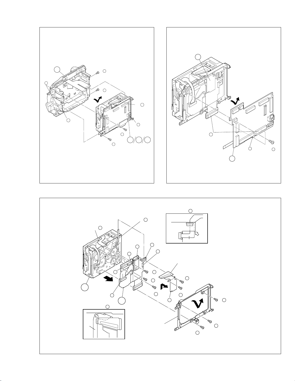
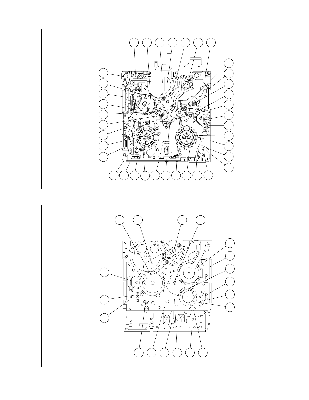
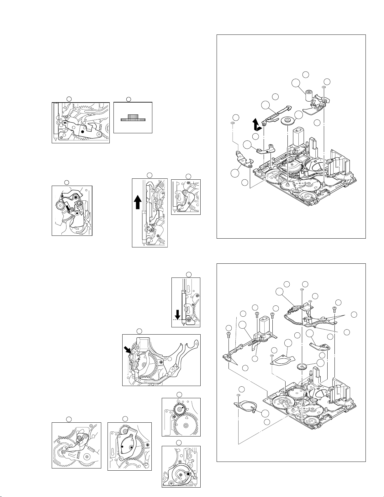
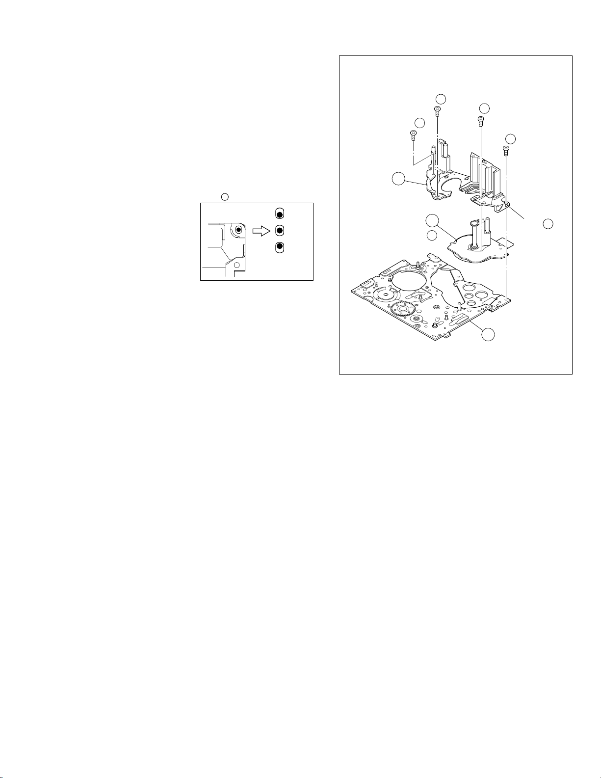
1.4 DISASSEMBLY OF THE 4 OP BLOCK AND CCD
BOARD ASSEMBLIES
1.4.1 Precautions
1. Take care in handling the CCD image sensor, optical LPF
and lens components2when performing maintenance
etc., especially with regard to surface contamination, attached dust or scratching. If fingerprints are present on
the surface they should be wiped away using either a
silicon paper, clean chamois or the cleaning cloth recommended by the Video Product Division.
2. The CCD image sensor may have been shipped with a
protective sheet attached to the transmitting glass. When
replacing the CCD image sensor, do not peel off this
sheet from the new part until immediately before it is
mounted in the OP Block Assembly.
1.4.2 How to remove
1. Remove the solder (SD1) from the 16 soldered points
on the CCD Board Assembly and take the assembly out.
2. Remove the two screws (1, 2) and take out the CCD Base
Assembly.
Note
a:
When removing the CCD Base Assembly, be
4
careful not to take out the CCD image sensor together with the spacer rubbers attached to it.
Note 4b:
The CCD image sensor should not be replaced
as a single part but should be replaced together
with the entire CCD Base Assembly.
1.4.3 How to install
1. With the spacer rubbers attached to the CCD base,
mount the CCD base in the OP Block Assembly and
tighten them together using the two screws (1, 2).
2. Mount the CCD Board Assembly and attach solder to
the 16 points (SD1).
1.4.4 Replacement of Service Repair Parts
The service repair parts for the OP Block Assembly are as
listed below.
Before replacement of these parts, remove the bracket (OP
assyembly) as required.
Take special care not to disconnect any of the FPC wires
or cause any damage due to soldering (excessive heating).
1. Focusing motor
2. Zoom motor
3. Iris motor unit
Note
c:
When replacing the focusing motor or the zoom
4
motor, solder the FPC at a space of about 1 mm
above the terminal pin.
When assembling, make sure that the slide section is positioned correctly.
Note 4d:
The iris motor unit includes the FPC Assembly,
switch and two sensors.
Note 4e:
Be careful not to damage the switch.
BRAKET (OP) ASSY
NOTE 4 c
ZOOM MOTOR
∗
3
4
(S c)
∗
4
4
(S c)
∗∗
10
4
(S b)
(S c)
(S b)
∗
9
4
∗∗
11
4
(S d)
∗
7
4
BLUE
OP
side
∗
5
4
(S c)
CCD
side
THIN
THICK
NOTE 4 a
OPTICAL LPF
∗
8
4
(S d)
∗
6
4
(S c)
(SD 1 )
NOTE 4 b
BASE ASSY
NOTE 4 a
SPACER RUBBER
FOCUS MOTOR
NOTE 4 c
∗
1
4
(S a)
∗
2
4
(S a)
CCD BORD ASSY
1-8
NOTE 4 c/ 4 d/ 4 e
IRIS MOTOR UNIT
Fig. 1-4-1
•
∗ : 0.118 N
∗∗ : 0.147 N•m (1.5kgf•cm)
m (1.2kgf•cm)
Page 13
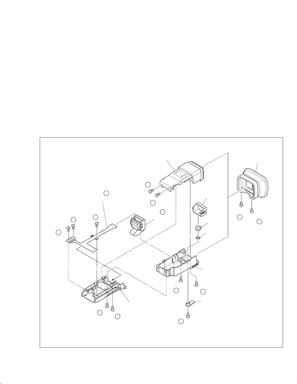
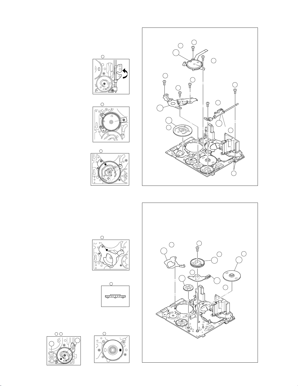
1.57 E.VF(COLOR)
1.5.1. Disassembly/Assembly of the 7 E.VF(COLOR)
1. Remove the two screws (1 and 2) and then remove the
EYE CUP.
2. Remove the two screws (3 and 4).
3. Pull out the VF assembly and then remove the three
screws (5 to 7) to release the FPC ASSY.
4. Remove the two screws (8 and 9) then lift the E.VF from
the BRACKET (VF) ASSY and take out the FPC ASSY.
Note
a :
Be careful not to disconnect or break the FPC
7
ASSY wire.
5. Remove the two screws (10 and 11) to remove the UPPER CASE ASSY.
6. Remove the LCD UNIT from the BOTTOM CASE ASSY.
Note
b :
Refer to the parts list for detail of the parts.
7
7. Remove the screw (12) and then remove the HOLD ASSY
(for lens), LINK (for lens), wave washer, LEVER (for lens).
5
7
(S c)
6
7
(S c)
NOTE a
FPC ASSY
7
7
(S d)
UPPER CASE ASSY
3
7
(S b)
7
4
7
(S b)
NOTE b
7
LCD UNIT
HOLD ASSY
(for lens)
LINK
(S a)
(for lens)
∗
1
7
EYE CUP
∗
2
7
(S a)
Wave
washer
BOTTOM CASE ASSY
10
7
(S e)
11
7
(S e)
8
7
(S e)
BRACKET (VF) ASSY
9
7
(S e)
Fig. 1-5-1
∗
12
7
(S e)
LEVER (for lens)
: 0.059 N•m (0.6kgf•cm)
∗
1-9
Page 14
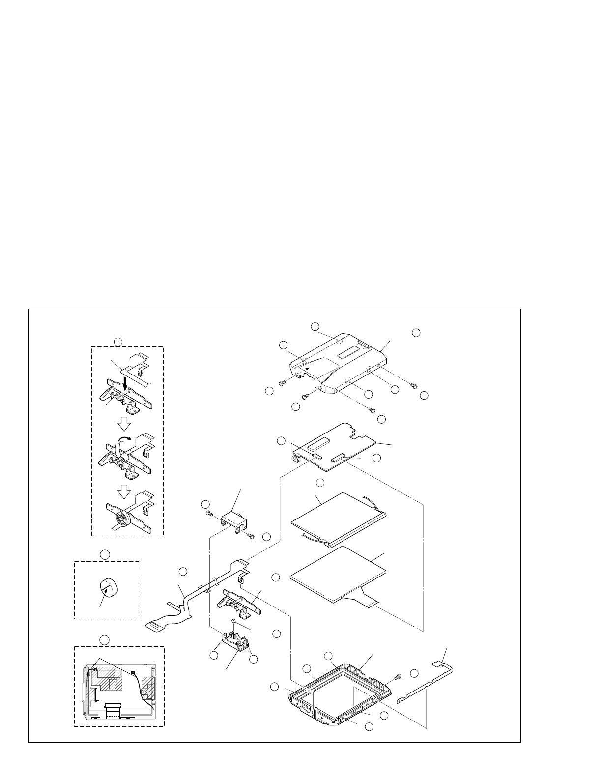
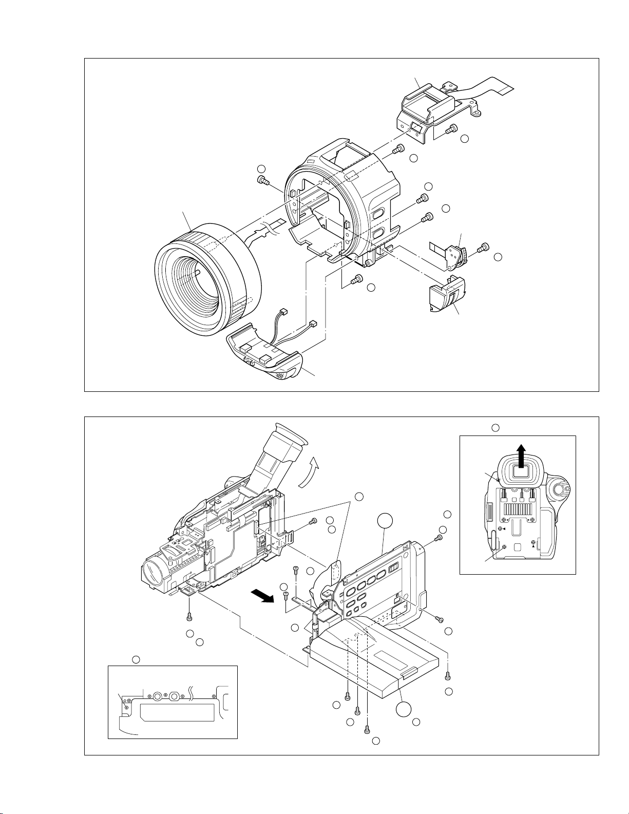
1.6 DISASSEMBLY/ASSEMBLY OF THE @ MONITOR
ASSEMBLY
1.6.1
Monitor Assembly and Hinge Assembly
@
Note:
Before proceeding to the work, separate the Monitor As-
•
sembly from the Upper Case Assembly as required.
1. Remove the four screws (1 to 4), disengage the four
hooks (L@a to L@d) in order, and take out the Monitor
Cover Assembly.
2. Unlock the connector ( @a ) and, while lifting the Hinge
Assembly, unplug and take out the FPC.
3. Remove the screw (5) and take out the bracket (MONI-
TOR CASE).
4. Unplug the FPC from the connector ( @b ) and take out
the Monitor Board Assembly and the backlight.
5. Remove the LCD module by disengaging the five hooks
(L@e to L@j).
6. Remove the two screws (6, 7) and take out the hinge
covers (U, L) by disengaging the four hooks (L@k, L@l)
at both sides of each of the hinge covers.
7. Remove the FPC Assembly from the Hinge Assembly.
12
NOTE e,g
FPC ASSY
HINGE
ASSY
∗
1
12
(S a)
Note
Note @b:
Note @c:
Note @d:
Note @e:
Note @f:
Note @g:
12
(L a)
(S a)
∗
2
12
a:
Be careful not to damage the FPC or the connec-
@
tor when removing the Monitor Cover Assembly.
Be careful not to damage the parts when remov-
ing or mounting the Hinge Assembly.
To unplug the FPC, release only the lock of the
connector and remove the FPC together with the
Hinge Assembly.
As the backlight is soldered at two points on the
Monitor Board Assembly, the solder should be removed when disassembling the backlight as a single part.
Take care when handling the FPC.
Be careful not to lose the magnets and attach
them in the correct orientation.
When mounting the FPC Assembly, wrap it around
the Hinge Assembly by 3-1/2 turns.
12
(L d)
a
12
(L b)
(S b)
3
12
12
NOTE a
MONITOR COVER ASSY
12
(L c)
4
12
(S b)
12
NOTE f
MARKING
12
NOTE d
WIRE
12
NOTE c,e
FPC ASSY
CN a
HINGE COVER (L)
6
12
(S d)
7
12
(S d)
NOTE b
HINGE ASSY
MAGNETS
NOTE
12
(L k)
HINGE COVER (U)
∗ : 0.118 N•m (1.2kgf•cm)
12
(L l)
(L j)
12
12
12
f
12
12
NOTE d
BACK LIGHT
(L g)
12
(L h)
CN b
MONITOR CASE ASSY
12
12
(L f)
MONITOR BOARD ASSY
12
LCD MODULE
5
12
(S c)
12
(L e)
BRACKET
(MONI CASE)
1-10
Fig. 1-6-1
Page 15
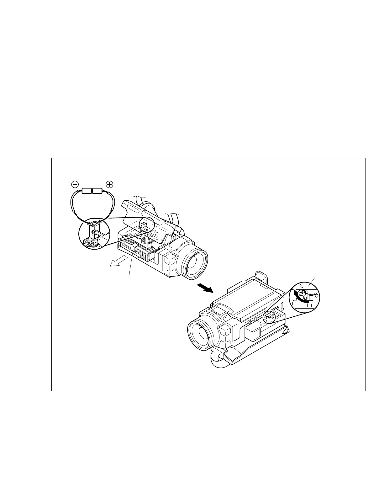
1.7 MANUAL EJECTION OF THE CASSETTE TAPE
Note:
The following procedure describes a simplified method
of ejecting the cassette tape in case it is not possible
to eject it, due to an electrical failure.
Be careful not to damage any of the parts or the tape
when performing repairs or maintenance work.
1. Remove the Power Unit (battery, DC code, etc.) from the
main unit.
2. Open the cassette cover.
3. Attach a piece of PVC tape at the front of the cassette
housing.
Note:
This helps prevent the tape from being damaged when
the Cassette Housing Assembly is moved upward at
the unloading end.
(DC3V)
4. In order to change the mechanism mode at the unloading end apply 3 V, DC to the electrode on the top surface of the Loading Motor Assembly and then set it to
the eject mode.
5. If there is any slack tape in the tape transport system,
wind it inside the cassette tape by turning the Supply
Reel Disk from the backside of the Slide Deck Assembly.
6. Peel off the PVC tape and take out the cassette tape from
the cassette housing.
Note:
Make sure that grease or a similar substance is not
attached to the surface of the tape.
Similarly, also make sure that grease or a similar sub-
stance is not attached on the Mechanism
Assembly.
PVC TAPE
REEL DISK ASSY (SUP)
Fig. 1-7-1
1-11
Page 16

1.8 EMERGENCY DISPLAY
Whenever some abnormal signal is input to the syscon
CPU, an error number (E01, as an example) is displayed
on the LCD monitor or (in the electronic view finder).
In every error status, such the message as shown below
alternately appear over and over.
• In an emergency mode, all operations except turning on/
off the POWER switch are ineffectual.
Example (in case of the error number E01):
UNIT IN
E01
SAFEGUARD MODE
E01
REMOVE AND
REATTACH BATTERY
LCD
display
E01 LOADING
E02 UNLOADING
E03 TU & SUP REEL
E04 DRUM FG
Emergency
mode
FG
Details Possible cause
In the case the encoder position is not shifted
to the next point though the loading motor has
rotated in the loading direction for 4 seconds
or more. This error is defined as [E01].
In the case the encoder position is not shifted
to the next point though the loading motor has
rotated in the unloading direction for 4 seconds or more. This error is defined as [E02].
In the case no REEL FG is produced for 4 seconds or more in the capstan rotation mode after loading was complete, the mechanism
mode is shifted to STOP with the pinch roller
set off.
This error is defined as [E03].
However, no REEL EMG is detected in the
SLOW/STILL mode.
In the case there is no DRUM FG input in the
drum rotation mode for 4 seconds or more.
This error is defined as [E04], and the mechanism mode is shifted to STOP with the pinch
roller set off.
1. The mechanism is locked during mode shift.
2. The mechanism is locked at the mechanism loading end, because the encoder position is skipped
during mechanism mode shift.
3. No power is supplied to the loading MDA.
1. The mechanism is locked during mode shift.
2. The mechanism is locked at the mechanism loading end, because the encoder position is skipped
during mechanism mode shift.
1. The idler gear does not engage with the reel disk
well.
2. Though the idler gear and reel disk are engaged with
each other, the tape is not wound because of overload to the mechanism.
3. No FG pulse is output from the reel sensor.
4. No power is supplied to the reel sensor.
5. Tape transport operation takes place with a cassette
having no tape inside.
6. The tape slackens and no pulse is produced until
the slack is taken up and the tape comes into the
normal status.
1. The drum cannot be started or drum rotation is
stopped because tape transport load is too high.
1) Tape tension is extremely high.
2) The tape is damaged or soiled with grease, etc.
2. The DRUM FG signal is not received by the syscon
CPU.
1) Disconnection in the middle of the signal line.
2) Failure of the DRUM FG pulse generator (hall element).
3. No drum control voltage is supplied to the MDA.
4. No power is supplied to the DRUM MDA.
E05 –
E06 CAPSTAN FG
1-12
– –
In the case no CAPSTAN FG is produced in
the capstan rotation mode for 2 seconds or
more. This error is defined as [E06], and the
mechanism mode is shifted to STOP with the
pinch roller set off.
However, no CAPSTAN EMG is detected in the
STILL/FF/REW mode.
1. The CAPSTAN FG signal is not received by the
syscon CPU.
1) Disconnection in the middle of the signal line.
2) Failure of the CAPSTAN FG pulse generator (MR
element).
2. No capstan control voltage is supplied to the MDA.
3. No power is supplied to the CAPSTAN MDA.
4. The capstan cannot be started or capstan rotation
is stopped because tape transport load is too high.
1) Tape tension is extremely high. (Mechanical
locking)
2) The tape is damaged or soiled with grease, etc.
(Tape tangling occurs, etc.)
Table 1-8-1
(DVC_03)
Page 17

1.9 SERVICE NOTE
1234 5
99 99 9 9
6 7 8 9 10 11 12 13 14 15 16 17 18 19 20 21 22 23
1
Fig. 1-3-1
Fig. 1-3-2a
Fig. 1-3-2cFig. 1-3-2b
Symbol No.
Removing order of screw
Place to stick screw
Reference drawing
Screw tightening torque
→
→
→
→
Symbol No.
Removing order of screw
Place to stick screw
Reference drawing
Screw tightening torque
→
→
→
→
→
Symbol No.
Removing order of screw
Place to stick screw
Reference drawing
Screw tightening torque
→
→
→
→
→
12
34 567
MONITOR ASSY
I
III
Removing order of screw
Place to stick screw
Reference drawing
Screw tightening torque
→
→
→
→
4
OP BLOCK ASSY
Fig. 1-4-1
IVIII
12
34
5678
9
10
11
< NOTE >
1)
9
;
Don't reuse the screw, because screw lock bond was applied to them.
2) Pay careful attention to tightening torque for each screw.
I
: 0.069N·m (0.7kgf
·cm)
: 0.078N
·m (0.8kgf·cm)
IIIII
: 0.059N·m (0.6kgf·cm)
IV
: 0.118N·m (1.2kgf
·cm)
V: 0.147N
·m (1.5kgf·cm)
Fig. 1-6-1
→
9999
99
I
99 9 9999
24 25 26 27 28 29 30 31 32 33 34 35 –
–
36 37 38 39 40 41
3
5
2
764
Fig. 1-3-3 Fig. 1-3-4 Fig. 1-3-5 Fig. 1-3-6 Fig. 1-3-7
II
42 43 44 45 46
99
47 48 49 50 51 52 53 54
098!
@
Fig. 1-3-8
Fig. 1-3-9 Fig. 1-3-10
/
Symbol No.
Removing order of screw
Place to stick screw
Reference drawing
Screw tightening torque
→
→
→
→
→
IIII
7
Fig. 1-5-1
E. VF ASSY
VVI
12345 67 8
9101112
Table 1-9-1
1-13
Page 18

SECTION 2
MECHANISM ADJUSTMENT
2.1 PRELIMINARY REMARKS ON ADJUSTMENT AND
REPAIR
2.1.1 Precautions
1. When fastening parts, pay careful attention to the tight-
ening torque of each screw. Unless otherwise specified,
tighten a screw with the torque of 0.039 N
2. Be sure to disconnect the set from the power supply be-
fore fastening and soldering parts.
3. When disconnecting/connecting wires, be careful not to
get them and their connectors damaged. (Refer to the
Section 1.)
4. When replacing parts, be very careful neither to dam-
age other parts nor to fit wrong parts by mistake.
5. In the following work, use the patch cords as required.
For details of the patch cords, see the “4.1 BOARD INTERCONNECTIONS” (SECTION 4, CHART AND DIAGRAM).
6. Some mechanism parts may be added to or deleted from
the parts list depending on a particular product modification.
Please refer to the “SECTION 5, PARTS LIST” for details
of the parts available.
2.1.2 Notes on procedure for disassemby/assembly
The disassembling procedure table (Table 2-4-1 on page
2-5,a part of the table is shown below for reference)shows
the procedure to disassemble/reassemble mechanism
parts.
Carefully read the following explanation before starting actual disassembling/reassembling work. The item numbers
(circled numbers)in the following explanation correspond
to those appearing under respective columns of the table.
(1) Circled numbers appearing in this column indicate the
order to remove parts. When reassembling, follow these
numbers in the reverse order. Circled numbers in this
column correspond to those appearing in drawings of
this section.
(2) This column shows part names corresponding to circled
numbers in the left column.
•
m (0.4 kgf•cm).
(3) The symbol (T or B)appearing in this column shows the
side which the objective part is mounted on.
T =the upper side, B =the lower side
(4) Symbols appearing in this column indicate drawing
numbers.
Step Part Name Fig. Point Note Remarks
(5) This column indicates parts and points such as screws,
washers,springs,and others to be removed/fitted for disassembling/reassembling the mechanism. Besides such
the parts, this column occasionally indicates working
points.
P = Spring
W = Washer
S = Screw
∗ = Lock (L),soldering (SD),shield,connector (CN),
etc.
Example • Remove ((W1)=Washer W1.
• ∗Remove the solder at (SD1)=Point SD1.
• ∗Disconnect
(6) Numbers in this column represent the numbers of notes
in the text.For example, “1” means “Note 1”.
(For parts that need phase adjustment after reassembling, refer to “2.6 MECHANISM ADJUSTMENTS”.)
(7) This column indicates required after-disassembling/-re-
assembling work such as phase adjustment or mechanism adjustment.
=Connector Å .
Å
NO. PART NAME FIG. POINT NOTE REMARKS
1 CASSETTE HOUSING ASSY T Fig.2-4-3 3(S1),(L1a)-(L1e)
2 UPPER BASE ASSY T Fig.2-4-4 (S2),(L2a),(L2b)
3 DRUM ASSY T (S3a),2(S3b)
4 REEL DISK ASSY(SUP) T Fig.2-4-5 (W4)
5 REEL DISK ASSY(TU) T (W5)
6 REEL COVER ASSY T 2(W6),(S6a),2(S6b)
(1) (2) (3) (4) (5) (6) (7)
2-1
NOTE1a,b,c,d
NOTE
2
NOTE3a,b
NOTE4a
NOTE
5
NOTE
6
ADJUSTMENT
ADJUSTMENT
Page 19
2.2 JIGS AND TOOLS REQUIRED FOR DISASSEMBLY,
ASSEMBLY AND ADJUSTMENT
2.2.1 Tools required for adjustments
1
3
5
7
9
11
13
15
Torque driver
YTU94088
Tweezers
P-895
Guide driver (Hexagonal)
D-770-1.27
Slit washer installation jig
YTU94121A
Jig connector cable
YTU93106B
Communication cable
YTU93107A
Alignment tape
MC-2
Cleaning cloth
KSMM-01
2
Chip IC replacement jig
4
6
Service support system
8
10
12
14
Bit
YTU94088-003
PTS40844-2
Adjustment driver
YTU94028
YTU94057-55
Extension connector
YTU94145C-30
PC cable
QAM0099-002
Cassette torque meter
YTU94151A
1. Torque driver
Be sure to use to fastening the mechanism and exterior
parts because those parts must strictly be controlled for
tightening torque.
2. Bit
This bit is slightly longer than those set in conventional
torque drivers.
3. Tweezers
To be used for removing and installing parts and wires.
4. Chip IC replacement jig
To be used for adjustment of the camera system.
5. Guide driver (Hexagonal)
To be used to turn the guide roller to adjustment of the
linarity of playback envelope.
6. Adjustment driver
To be used for adjustment.
7. Slit washer installation jig
To be used to install slit washers.
8. Service support system
To be used for adjustment with a personal computer.
9. Jig connector cable
Connected to CN107 of the main board and used for
electrical adjustment, etc.
10. Extension connector
Connect this extension connector to the connector of the
jig connector cable for extending the cable connector.
Removing the cover (for jig), use this extension con-
Note:
nector double for connecting the jig connector cable.
11. Communication cable
Connect the Communication cable between the PC cable and Jig connector cable when performing a PC adjustment.
12. PC cable
To be used to connect the VideoMovie and a personal
computer with each other when a personal computer is
used for adjustment.
13. Alignment tape
To be used for check and adjustment of interchangeability of the mechanism.
14. Cassette torque meter
This is used to cheek the back tension and play torque
during mechanism adjustment.
When using the cassette torque meter, install the
Note:
service support system software in advance.
•
LED : Forced to ON
•
EJECT SW : OFF (Cancel)
The above setting is required to prevent any tape
damage that may occur because the cassette
torque meter cannot detect the leading/trailing sections of the tape.
15. Cleaning cloth
Recommended cleaning cloth to wipe down the video
heads, mechanism (tape transport system), optical lens
surface.
Table 2-2-1
2-2
Page 20
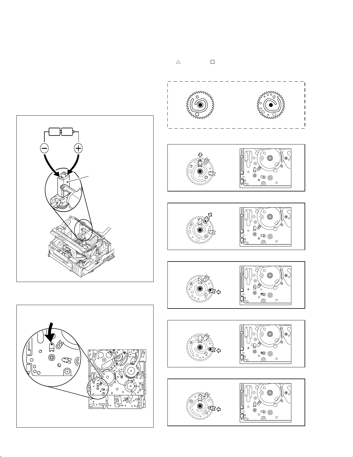
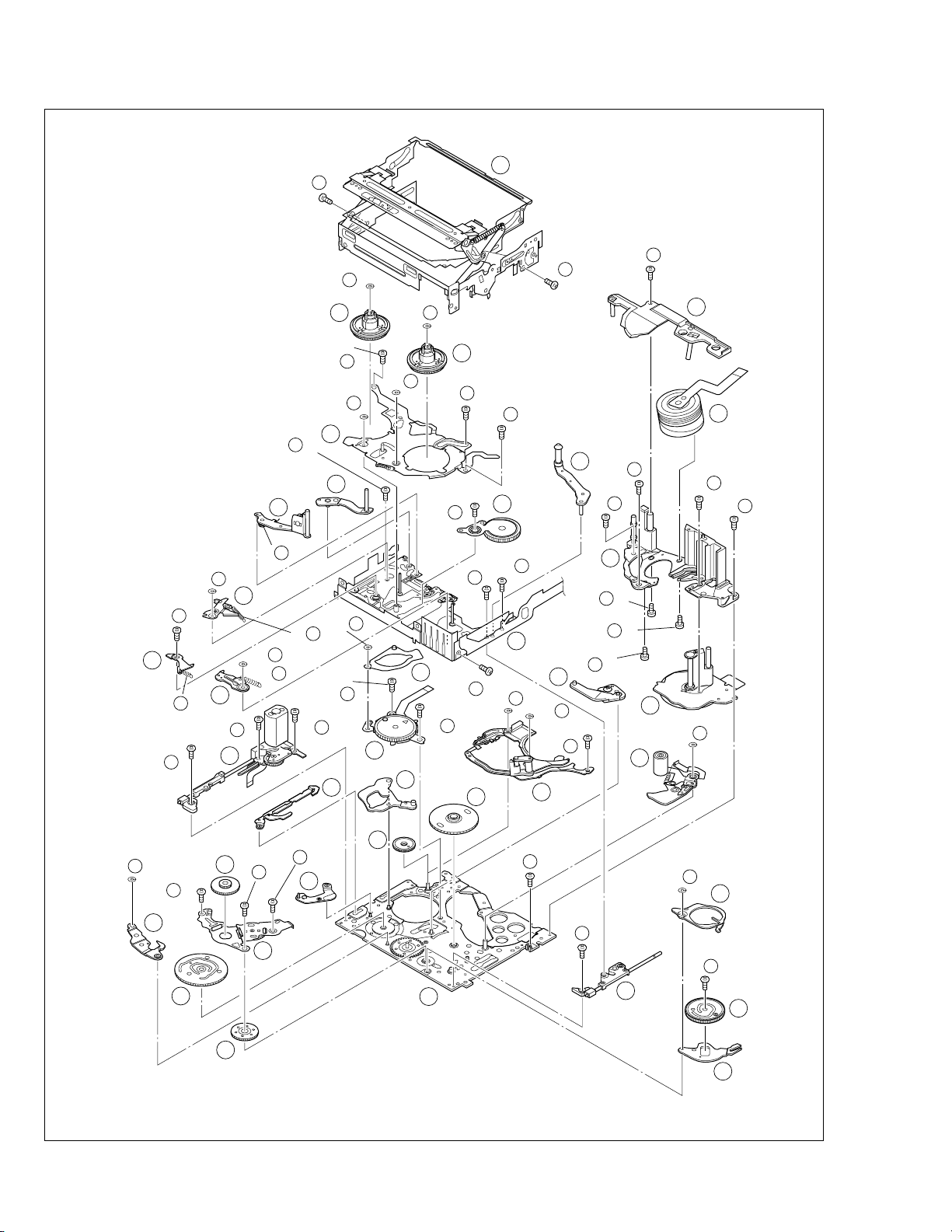
2.3 DISASSEMBLY/ASSEMBLY OF MECHANISM ASSEMBLY
2.3.1 General statement
The mechanism should generally be disassembled/assembled in the C.IN mode (ASSEMBLY mode). (Refer to Fig.
2-3-1,2.)
However, when the mechanism is removed from the main
body, it is set in the STOP mode. Therefore, after the
mechanism is removed from the main body, supply 3 V DC
to the electrode on the top of the loading motor to enter
the mechanism mode into the C,IN mode compulsory.
<Mechanism assembly/Cassette housing assembly>
2.3.2 Explanation of mechanism mode
The mechanism mode of this model is classified into five
modes as shown in Table 2-3-1. Each mechanism mode
can be distinguished from others by the relative position
”, “Q”, “Q” “ ” marks on the sub cam gear to the in-
of “
ner or outer protrusion on the main deck.
Refer to Fig. 2-3-3 to 2-3-8 below.
<SUB CAM GEAR>
DC3V
TOP VIEW BOTTOM VIEW
Fig. 2-3-3
<C IN mode>
LOADING MOTOR
Fig. 2-3-4
<SHORT FWD mode>
Fig. 2-3-5
<STOP mode>
Fig. 2-3-1
<Back side of the mechanism assembly>
C IN mode
Back side of deck
Fig. 2-3-2
2-3
Fig. 2-3-6
<REV mode>
Fig. 2-3-7
<PLAY mode>
Fig. 2-3-8
Page 21
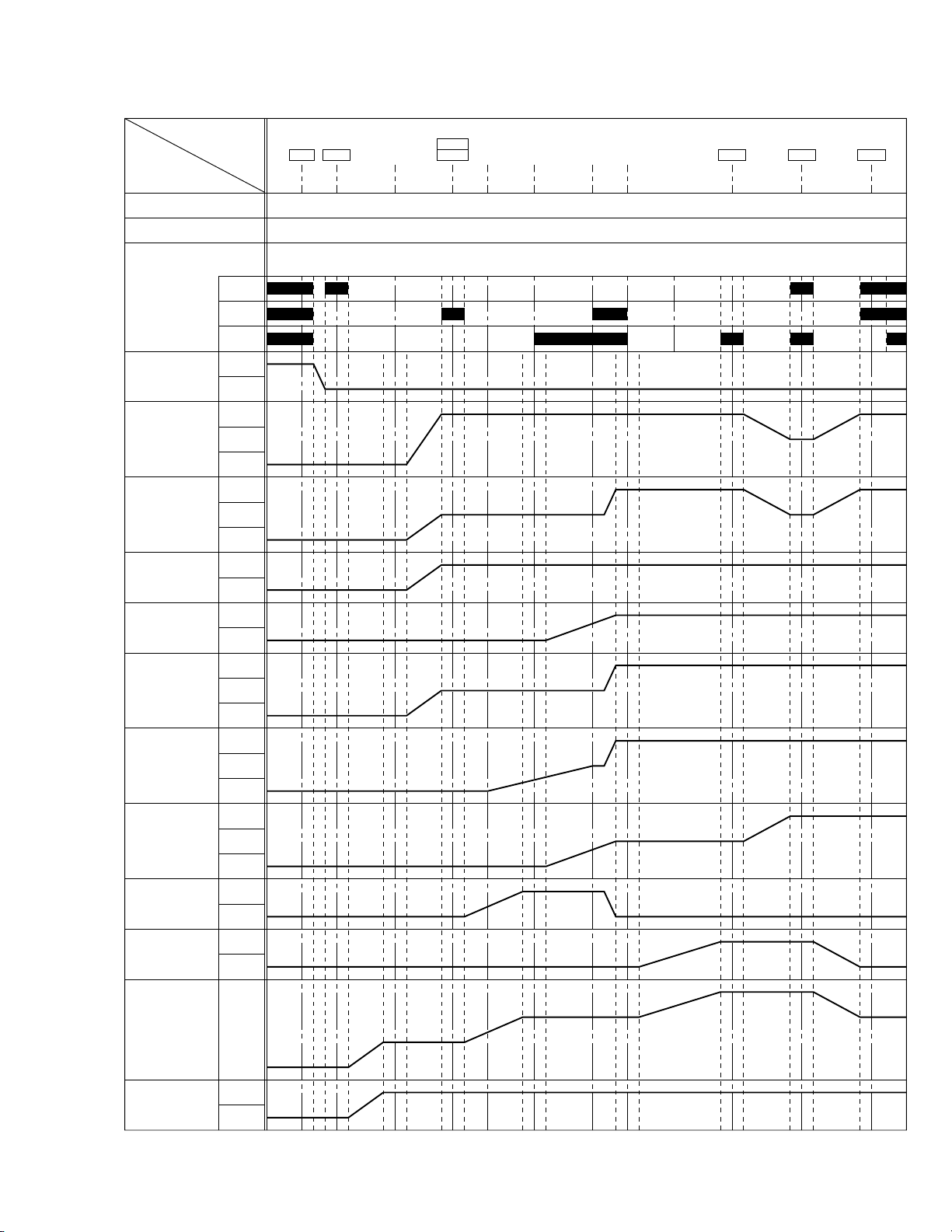
EJECT LEVER
PARTS
MODE
ON
EJECT
RELEASE
-15° (27.14°) (84.08°) (97.35°) (182.10°) (185.63°)71°0°
-13°-3° 3° 68°
215°
212° 218°
257.3°
254.3° 260.3°
295°
-12.40° (22.44°) (69.53°) (80.5°) (150.58°) (153.5°)58.71°0° 177.79° 212.77° 243.94°
-16.97° (30.71°) (95.14°) (110.06°) (206.06°) (210.05°)80.34°0° 243.29° 291.16° 333.82°
292° 310°74°
L. END
LOCK
OFF
TU ARM
ON
OFF
SLIDE DECK
LOAD
UL
BRAKE (S)
ON
OFF
BRAKE (T)
ON
OFF
RELEASE
LEVER
ROTARY
ENCODER
MAIN CAM
SUB CAM
ON
a
OFF
CTL PLATE
C
R
L
TENSION ARM
UL
L. END
OFFPAD ARM
UL
L. END
LOADSUP. L. ARM
UL
L. END
LOADTU. L. ARM
UL
PRESS
LOADP. ROLLER
UL
b
c
CAS. IN
SHORT
STOP PLAYREVFWD
TU. P. B
START
TU. P. B
END END
SLIDE SLIDE
START
2.3.3 Mechanism timing chart
Table 2-3-1
2-4
Page 22

2.4 DISASSEMBLING PROCEDURE TABLE
MARK: 夝 After assembly, perform adjustments.
NO. PART NAME FIG. POINT NOTE REMARKS
1 CASSETTE HOUSING ASSY T Fig.2-4-3 3(S1),(L1a)-(L1e)
2 UPPER BASE ASSY T Fig.2-4-4 (S2),(L2a),(L2b)
3 DRUM ASSY T (S3a),2(S3b)
4 REEL DISK ASSY(SUP) T Fig.2-4-5 (W4)
5 REEL DISK ASSY(TU) T (W5)
6 REEL COVER ASSY T 2(W6),2(S6a),(S6b)
7 TENSION ARM ASSY T Fig.2-4-6 —
8 SLANT POLE ARM ASSY T (P8)
9 TU ARM ASSY T —
10 SWING ARM ASSY T (S0)
11 SLIDE DECK ASSY T Fig.2-4-7a 2(S!a),(S!b),2(L!a),
2(L!b),(L!c)
12 PAD ARM ASSY T Fig.2-4-7b (P@),(L@),(W@)
13 SUP BRAKE ASSY T (P#),(L#),(S#)
14 TU BRAKE ASSY T (P$),(L$),(W$)
15 TENSION CTL LEVER ASSY T Fig.2-4-8 (W%)
16 CENTER GEAR T —
17 PINCH ROLLER ARM F. ASSY T (W&)
18 TENSION CTL PLATE ASSY T —
19 BRAKE CTL LEVER ASSY T —
20 MOTOR BRACKET ASSY T Fig.2-4-9 3(S)),(L)a),2(L)b)
21 GUIDE RAIL ASSY T
22 SLIDE LEVER 2 ASSY T —
23 LOADING PLATE ASSY T (W‹)
24 MODE GEAR T —
25 EJECT LEVER T (Wfi)
26 BASE R ASSY T Fig.2-4-10 (Sfla),(Sflb),2(Lfl)
27 ROTARY ENCODER T 2(S‡)
28 GEAR COVER ASSY T (S°a),2(S°b)
29 MAIN CAM ASSY T —
30 SLIDE ARM ASSY T Fig.2-4-11 —
31 CONNECT GEAR 2 T —
32 SUB CAM ASSY T (S™)
33 CONTROL ARM ASSY T —
34 REEL GEAR 1 T —
35 / 36
36 CAPSTAN MOTOR T (S§)
37 MAIN DECK ASSY T —
DRUM BASE ASSY/ T Fig.2-4-12 3(S∞)
CAPSTAN MOTOR
2(W⁄),(S⁄),2(L⁄a),(L⁄b)
NOTE1a,b,c,d
NOTE
2
NOTE3a,b
NOTE
4
NOTE
5
NOTE
6
NOTE
7
NOTE
8
NOTE
9
NOTE
0
NOTE!a,b
NOTE
@
NOTE
#
NOTE
$
NOTE
%
NOTE
^
NOTE
&
NOTE
*
NOTE
(
NOTE
)
NOTE
⁄
NOTE
¤
NOTE
‹
NOTE
›
NOTE
fi
NOTE
fl
NOTE
‡
—
NOTE
·
NOTE
‚
NOTE
¡
NOTE
™
NOTE
£
NOTE
¢
NOTE∞a,b
NOTE
§
—
ADJUSTMENT
ADJUSTMENT
ADJUSTMENT / 夝
ADJUSTMENT
ADJUSTMENT
ADJUSTMENT
ADJUSTMENT / 夝
ADJUSTMENT / 夝
ADJUSTMENT
ADJUSTMENT
ADJUSTMENT
ADJUSTMENT
ADJUSTMENT
ADJUSTMENT
ADJUSTMENT
ADJUSTMENT / 夝
ADJUSTMENT
ADJUSTMENT
ADJUSTMENT
PHASE ADJUSTMENT
PHASE ADJUSTMENT
ADJUSTMENT
PHASE ADJUSTMENT
ADJUSTMENT
ADJUSTMENT
ADJUSTMENT
2-5
Table 2-4-1
Page 23
24 27 2 3 36 3521
26
17
34
9
10
33
26
6
5
25
11
32
37
143128161530
29
13
4
12
7
8
22
18
23
20
19
< TOP VIEW >
< BOTTOM VIEW >
26
32
25
34
Fig. 2-4-1
36 3 22
27
20
30
18
19
29
31 16 6
37
11
30
Fig. 2-4-2
2-6
Page 24
2.4.1 Disassembly/assembly
1
(S )
1
2
(S )
1
1
NOTE d
1
NOTE c
1
NOTE b
1
NOTE a
1
(S )
1
3
(L d)
LOCK
LEVER
1
(L a)
1
(L e)
1
(L c)
1
(L b)
1
NOTE d
1
CASSETTE HOUSING ASSY
1.
1
NOTE1a:
Be careful not to damage any of the
parts during work.
NOTE1b:
Special care is required in mounting.
1
NOTE b
NOTE1c:
NOTE c
When mounting, the CASSETTE
HOUSING ASSY should be attached in the Eject status. Pay
heed to the positions of the LOCK
LEVER and EJECT LEVER during
mounting.
NOTE1d:
When mounting, be sure to locate the
FPC in the gap.
2.
UPPER BASE ASSY
2
DRUM ASSY
3
NOTE
NOTE2:
When mounting, be sure to insert
the FPC reinforcing sheet.
1
EJECT
LEVER
NOTE d
2
1
LOCK
LEVER
Fig. 2-4-3
4
2
(S )
2
NOTE3a:
Be mindful of scratches or damage
during work.
NOTE3b:
Be careful not to attach screws incorrectly.
2-7
NOTE
5
2
NOTE
2
(L b)
3
NOTE
3
b
7
3
6
3
(S b)
(S b)
a
7
3
5
3
(S a)
3
NOTE b
2
(L a)
NOTE
2
6
Fig. 2-4-4
Page 25
REEL DISK ASSY(SUP)
3.
4
REEL DISK ASSY(TU)
5
REEL COVER ASSY
6
NOTE4:
Be careful not to attach the REEL DISK wrongly. The Supply side can be identified by the white color at the center.
4 5
NOTE ,
NOTE5:
Be careful not to attach the
REEL DISK wrongly. The
REEL DISK ASSY
WHITE
BLACK
Take-up side can be identified by the black color at
the center.
NOTE
4
(W )
4
8
6
(S a)
6
(W )
4
(W )
5
(W )
6
NOTE
5
10
6
(S b)
5
9
6
(S a)
SUP
TU
NOTE6:
Perform the following steps for mounting.
1. Align the 2 holes with the pins.
2. Attach the PINCH ROLLER ARM ASSY by aligning the
positions.
3. Attach the SUB DECK
ASSY by aligning the
NOTE
6
53
2,6
positions.
4. Check that the parts
below them are located in the correct
positions.
4
5. Tighten the 2 screws.
6. Tighten the screw.
7. Attach the 2 SLIT
WASHER parts.
1, 7
4.7 TENSION ARM ASSY
SLANT POLE ARM ASSY
8
TU ARM ASSY
9
SWING ARM ASSY
0
NOTE
7
NOTE7:
When detaching, remove the spring
of the
vance.
Pay attention to the attachment position.
NOTE8:
@
PAD ARM ASSY in ad-
NOTE
A
SPRING
8
When mounting the SLANT POLE
ARM ASSY, hook the spring onto
the lug as in diagram A, and fit the
combination onto the SLIDE DECK
ASSY. After fitting, hook the spring
SPRING
onto the lug of the SLIDE DECK
ASSY as in diagram B.
Be careful not to lose the spring.
B
NOTE
7
NOTE
6
NOTE
7
6
(P )
NOTE
NOTE
7
10
8
Fig. 2-4-5
8
(S )
10
8
11
10
NOTE
9
9
NOTE9:
Pay attention to the mounting position.
NOTE0:
When detaching, remove the screw
then remove the SWING ARM ASSY
by pulling it up and turning it.
NOTE
NOTE
9
10
Fig. 2-4-6
2-8
Page 26
5.
SLIDE DECK ASSY
!
NOTE!a:
Each of the parts on the SLIDE DECK ASSY can be replaced separately.
When detaching the assembly, if there is no need to replace
any of its parts, remove the SLIDE DECK ASSY as it is.
NOTE!b:
When mounting, pay attention to the positions of the
¤
SLIDE LEVER (2) studs and the ( BRAKE CONTROL LEVER ASSY.
When mounting, position the CONTROL PLATE on the left
side.
Pay attention to the position of the SLIDE GUIDE PLATE
during mounting.
11
NOTE
b
11
(L b)
14
11
(S b)
11
NOTE b
11
(L c)
13
11
(S a)
12
11
(S a)
(L a)
NOTE a
11
11
11
6.
PAD ARM ASSY
@
SUP BRAKE ASSY
#
TU BRAKE ASSY
$
NOTE@:
The spring may have already been disengaged when the
8
SLANT POLE ARM ASSY was removed.
NOTES$:
When mounting, pay attention to the correct positioning.
Mount the CONTROL PLATE by moving it fully toward the
left side.
12 13 14
NOTE
12
CONTROL
PLATE
SPRING
13 14
12
(W )
NOTE
(L )
13
13
12
(P )
15
(S )
13
NOTE
12
13
Fig. 2-4-7a
12
13
(P )
(W )
12
(L )
14
14
NOTE
(L )
14
(P )
14
14
2-9
Fig. 2-4-7b
Page 27
7.% TENSION CTL LEVER ASSY
(S )
20
18
(S )
20
17
(S )
20
16
(W )
23
(W )
21
(W )
21
(S )
21
19
21
22
23
20
24
25
(W )
25
(L b)
20
(L a)
20
(L a)
21
(L b)
21
NOTE
24
NOTE
22
NOTE
21
NOTE
23
NOTE
20
NOTE
25
CENTER GEAR
^
PINCH ROLLER ARM F. ASSY
&
TENSION CTL PLATE ASSY
*
BRAKE CTL LEVER ASSY
(
NOTES%/^:
When mounting, pay attention to the correct positioning.
15
NOTE
16
NOTE
(TOP)
(BOTTOM)
NOTES*/(:
When mounting, pay atten-
NOTE&:
Take care against grease
attachment during work.
17
NOTE
tion to the correct positioning.
18
NOTE
NOTE
19
15
(W )
NOTE
15
NOTE
15
19
NOTE
18
19
18
NOTE
17
16
NOTE
17
17
(W )
16
MOTOR BRACKET ASSY
8.
)
GUIDE RAIL ASSY
⁄
SLIDE LEVER 2 ASSY
¤
LOADING PLATE ASSY
‹
MODE GEAR
›
EJECT LEVER
fi
NOTE):
When mounting, pay attention to the positioning of the sliding parts.
NOTE
NOTE
23
22
NOTE⁄:
When mounting, take care
that no part is allowed to
float or rattle.
NOTES¤/‹/›/fi:
When mounting, pay attention to the
correct positioning.
NOTE
Fig. 2-4-8
20
NOTE
21
24
NOTE
NOTE
25
Fig. 2-4-9
2-10
Page 28
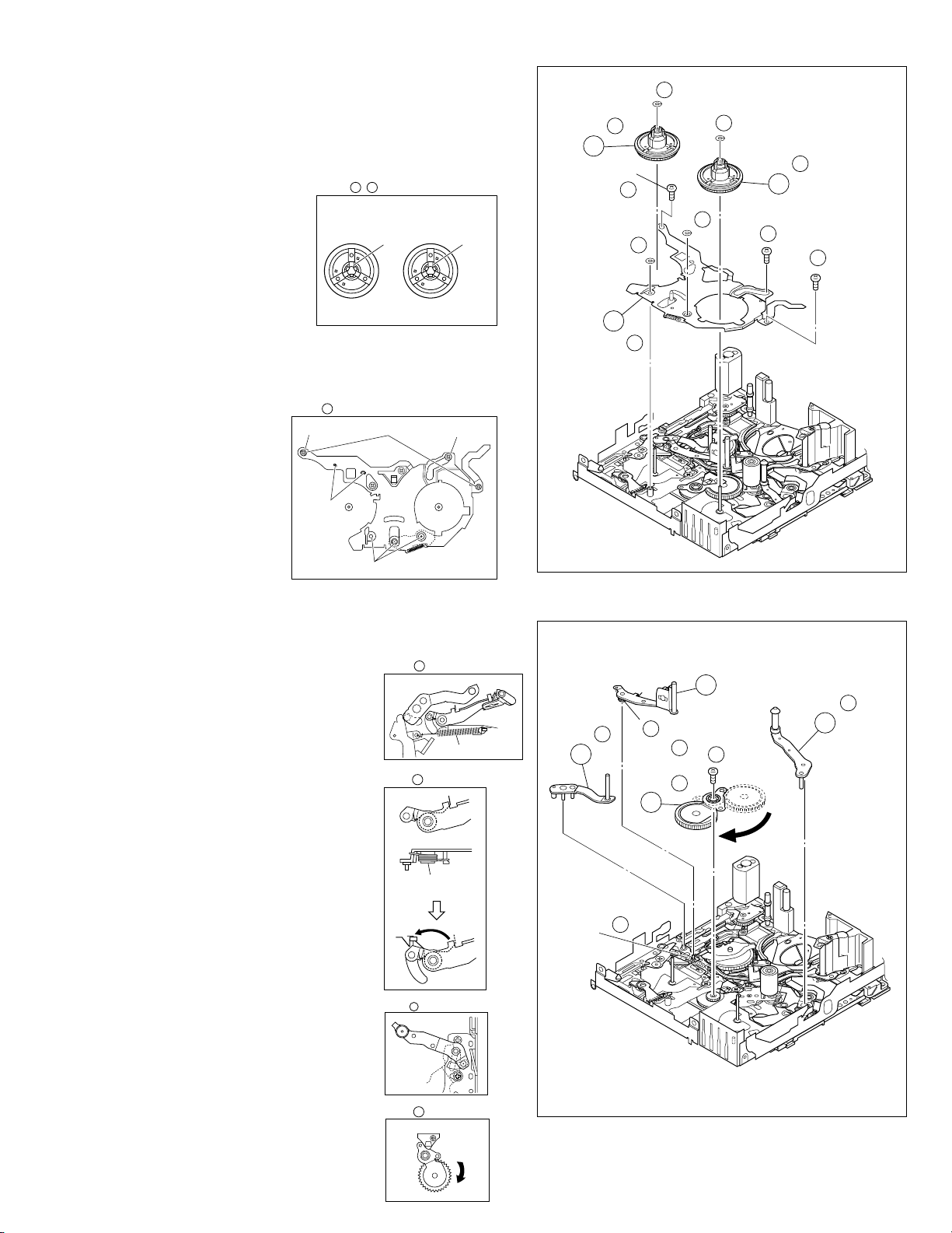
BASE R ASSY
9.
fl
ROTARY ENCODER
‡
GEAR COVER ASSY
°
MAIN CAM ASSY
·
NOTEfl:
When mounting, fold the sliding
part to the inner side.
NOTE
22
27
(S )
27
NOTE
26
27
23
27
(S )
25
26
28
24
28
(S a)
20
26
(S b)
28
(S b)
(S b)
NOTE‡:
When mounting, pay attention to
the correct positioning and the
FPC layout.
NOTE
·
:
When mounting, pay attention to
the correct positioning.
SLIDE ARM ASSY
10.
‚
CONNECT GEAR 2
¡
SUB CAM ASSY
™
CONTROL ARM ASSY
£
REEL GEAR 1
¢
NOTE
‚
:
When mounting, pay attention to the
correct positioning and the FPC layout.
NOTE
NOTE
NOTE
21
26
27
(S a)
28
29
29
NOTE
29
26
NOTE
26
26
(L )
Fig. 2-4-10
30
30
NOTE
30
27
32
(S )
NOTE
32
32
NOTE
34
34
NOTE¡:
When mounting, pay attention to the position of the front and back.
31
NOTE
(BOTTOM)
(TOP)
NOTES™/£/¢:
When mounting, pay attention to the correct positioning and
the FPC layout.
34
32 33
NOTE /
32
33
NOTE
2-11
NOTE
31
31
Fig. 2-4-11
33
NOTE
33
Page 29
11.
DRUM BASE ASSY
∞
CAPSTAN MOTOR
§
MAIN DECK ASSY
¶
NOTES
∞
a /§:
When detaching, remove them together and then separate
from ∞a.
§
∞
b:
NOTE
When mounting, attach the DRUM BASE ASSY so that the
screw hole is located at the center of the ellipse.
35
NOTE b
35
28
35
(S )
29
35
(S )
31
36
(S )
30
35
(S )
NG
OK
NG
NOTE
36
36
Fig. 2-4-12
37
NOTE
35
a
(Z27 Ver.4_P)
2-12
Page 30
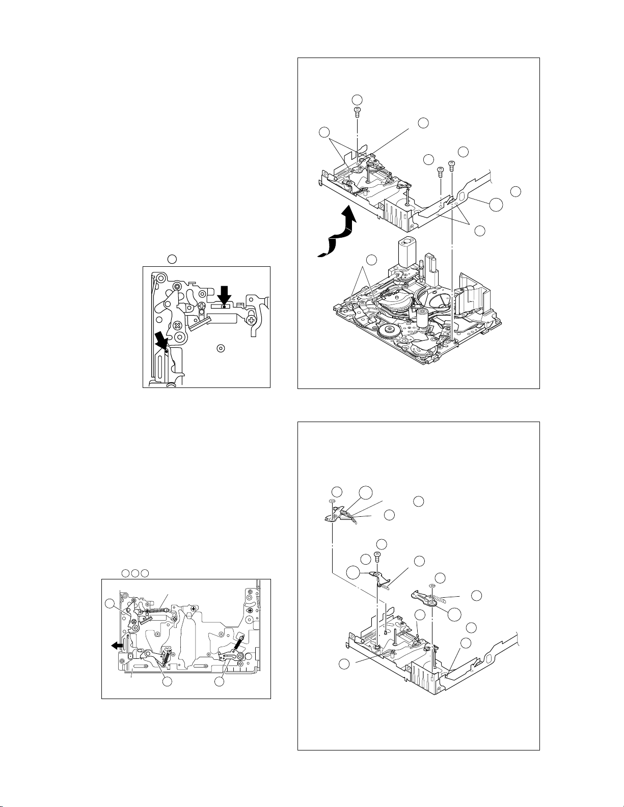
2.4.2 List of procedures for disassembly
(S )
13
(P )
18
(S )
20
15
13
13
12
(W )
14
(S )
20
17
12
20
(S b)
8
(P )
14
(W )
14
(P )
14
8
2
(S )
11
12
(P )
16
(S )
1
(W )
4
(S a)
(W )
6
7
(W )
22
(S )
20
18
27
1
4
29
35
(S )
35
5
3
2
(S )
36
17
2
(S )
17
(W )
31
3
36
30
35
(S )
1
1
4
5
(W )
8
6
6
(W )
6
5
10
6
(S b)
(S a)
(S )
9
6
9
21
19
21
28
(S )
35
7
3
(S b)
(S a)
6
3
(S b)
23
27
30
23
11
(S )
23
27
(S )
10
13
11
(S a)
3
1
(S )
34
10
12
11
(S a)
11
21
(W )
22
(W )
(S )
21
2-13
15
(W )
25
28
(S b)
15
29
16
31
26
28
(S b)
28
24
28
(S a)
19
24
37
Fig. 2-4-13
21
26
(S b)
20
26
(S a)
26
25
(W )
(S )
25
27
32
32
33
Page 31

2.5 CHECKUP AND ADJUSTMENT OF MECHANISM PHASE
MODE GEAR
Align the MODE GEAR with the Main Deck
Assembly hole.
ROTARY ENCODER
Mount the ROTARY ENCODER by aligning its mark ( )
and the mark ( ) of the Main Deck Assembly.
Note:
Be careful when handling the FPC during mounting.
MAIN CAM ASSY/ 30 SLIDE ARM ASSY
When mounting the SLIDE ARM ASSY align it with the
Main Deck Assembly and MAIN CAM ASSY holes.
Note:
During the mounting procedure, make sure that the 32 .
SUB CAM ASSY is in the correct mounting position.
SUB CAM ASSY/ 33 CONTROL ARM ASSY
Mount the SUB CAM ASSY hole to align with the CONTROL
ARM ASSY and Main Deck Assembly holes and then tighten
them all together with a screw.
The screw tightening torque should be 0.039 N•m (0.4 kgf•cm)
Note:
When mounting it, make sure that the 29 MAIN CAM ASSY is
in the correct mounting position.
REEL GEAR 1
Align the REEL GEAR 1 with
the Main Deck Assembly hole.
Note:
The REEL GEAR 1 may be
displaced during mechanism
operation, however this can
be checked from the rear and
realigned during manual
assembly.
Note:
The MODE GEAR may
be displaced during the
mechanism operation,
however it can be
checked from the rear
and realigned during
manual assembly.
24
29 32
34
27
Fig. 2-5-1
2-14
Page 32

2.6 MECHANISM ADJUSTMENTS
2.6.1 Adjustment of the slide guide plate
Use Fig. 2-6-1 as the reference unless otherwise specified.
1. Set the PLAY mode.
See Fig. 2-3-8.
2. Loosen the screws ( A , B ).
3. With the Main Deck and Slide Deck Assemblies pushed
into the unit, tighten the screws ( A , B ) while applying
pressure to the stud (shaft) on the Slide Guide plate.
The pressure applied should be enough to enable utilization of the rebounding force of the springs.
The tightening torque should be 0.069 N
•
m (0.7 kgf•cm).
4. Check the operation.
Repeat unloading and loading several times and make
sure that these operations can be performed smoothly
without producing rattles.
3
2, 3
SCREW
3
STUD
(SHAFT)
3
3
A
2,3
SCREW
B
3
2-15
Fig. 2-6-1
Page 33

3
3
SCREW
2, 3
A
2.6.2 Adjustment of the Tension Arm and Pad Arm Assemblies
Use Fig. 2-6-2 as the reference unless otherwise specified.
1. Set the PLAY mode.
Se Fig. 2-3-8.
2. Loosen the screw A .
3. With the take-up side at the bottom, align the extreme
end of the Tension Arm Assembly with the crossed
grooves on the screw B that retains the Loading Motor
Assembly and then tighten the screw A .
The tightening torque should be 0.069 N
•
m (0.7 kgf•cm).
4. Check the operation.
Repeat unloading and loading several times and make
sure that the Tension Arm Assembly is located within the
normal range.
Note :
With the above checking method, a Torque Meter is not used.
When a Torque meter is used, the following are
the reference values:
2.6.3 Adjustment of the Slide Lever 2
Use Fig. 2-6-3 as the reference unless otherwise specified.
1. Set the C IN mode.
See Fig. 2-3-4.
2. Loosen the screw A .
3. Set the Main Deck and Slide Deck Assemblies apart so
that they do not rattle, then tighten the screw A by
screwing it fully toward the Drum Assembly.
The tightening torque should be 0.069 N
•
m (0.7 kgf•cm).
4. Check the operation.
Repeat unloading and loading several times and make
sure that these operations can be performed smoothly
without producing rattles.
2, 3
SCREW
Back Tension : 2.0 to 6.0 g•cm
Play Torque : 8.3 to 12.5 g
SCREW
B
A
•
cm
TENSIOM
ARM ASSY
Fig. 2-6-3
Fig. 2-6-2
2-16
Page 34

2.7 SERVICE NOTE
Use the following chart to manage mechanism parts that are removed for disassembling the mechanism.
Fig.
1
CASSETTE HOUSING ASSY UPPER BASE ASSY
Fig.
2
2
I
4
I
3
Fig. Fig.
3
DRUM ASSY
2
I
4
I
4
2
I
4
I
5
REEL DISK ASSY(SUP)
4
REEL DISK ASSY(TU)
5
2
I
4
I
4
REEL COVER ASSY
6
Fig.
TENSION ARM ASSY
7
SLANT POLE ARM ASSY SWING ARM ASSYTU ARM ASSY
8 9
2
I
4
I
6
Fig. Fig.
2
I
4
I
7
a
SLIDE DECK ASSY
11
2
I
4
I
7
b
PAD ARM
ASSY
1312
10
SUP
BRAKE
ASSY
14
TU BRAKE
ASSY
2-17
Table 2-7-1a
Page 35

Fig.
2
I
4
I
8
TENSION CTL
15
LEVER ASSY
CENTER GEAR
16
PINCH ROLLER
17
ARM F. ASSY
TENSION
18
CTL PLATE
ASSY
BRAKE CTL
19
LEVER
ASSY
Fig.
2
I
4
I
9
Fig.
2
I
4
I
10
Fig.
MOTOR
20
BRACKET
ASSY
BASE R ASSY ROTARY
26
SLIDE ARM
30
ASSY
27
31
CONNECT
GEAR 2
GUIDE
21
RAIL ASSY
ENCODER
32
28
SUB CAM
ASSY
22
24
GEAR COVER
ASSY
33
SLIDE LEVER 2
ASSY
MODE GEAR EJECT LEVER
MAIN CAM ASSY
29
CONTROL
ARM ASSY
LOADING
23
PLATE ASSY
25
REEL GEAR 1
34
2
I
4
I
11
Fig.
2
I
4
I
12
DRUM BASE ASSY
35
CAPSTAN MOTOR MAIN DECK ASSY
36
Table 2-7-1b
37
2-18
Page 36

2.8 JIG CONNECTOR CABLE CONNECTION
Remove one screw (1) first and the cover (JIG) next.
COMMUNICATION CABLE JIG CONNECTOR
to 8 pin
RED
( JLIP_RX )
to 9 pin
( JLIP_TX )
WHITE
to 5 or 23 pin
BLACK
( GND )
JACK BOX
COVER
(JIG)
JIG CONNECTOR CABLE
COMMUNICATION CABLE
MAIN BOARD ASSY CN107
16
1
17
2
18
3
19
4
20
5
21
6
22
7
23
8
24
9
25
10
26
11
27
12
28
13
29
14
30
15
D_REG3V
SRV_RX
SRV_TX
DRST
TDO
TDI
TCMK
TMS
TRST
GND
SBE
SPA
TX2
RX2
GND
JLIP_RX
PB_CLK
JLIP_TX
GND
HID1
ENV_OUT
ATFI
DISCRI
MAIN_VCO
VPPD
AL_3VSYS
FS_PLL
VPPC
IF_TX
RST
1
Fig. 2-8-1
CN107
EXTENSION CONNECTOR
Removing the cover (for jig), use this extension
NOTE:
connector double for connecting the jig connector
cable.
TO PC CABLE
JIG CONNECTOR CABLE
1
2
3
4
5
6
7
8
9
10
11
12
13
14
15
16
17
18
19
20
21
22
23
24
25
26
27
28
29
30
NC
NC
NC
NC
GND
NC
NC
JLIP_RX
JLIP_TX
HID1
NC
MAIN_VCO
NC
NC
NC
NC
NC
NC
NC
NC
NC
TX2
GND
NC
NC
ENV_OUT
NC
NC
FS_PLL
NC
2-19
Fig. 2-8-2
Page 37

2.8.1 Tape pattern check
CN107
(ENV_OUT)
CN107
(HID1)
Flatten the waveform.
Misalignment of guide roller
height on the take-up side
Misalignment of guide
roller height on the
supply side
(1) Play back the compatibility adjustment tape.
(2) While triggering the MAIN CN107-10PIN (HID1), ob-
serve the waveform of CN107-26PIN (ENV_OUT).
(3) Confirm that the waveform is free from remarkable
level-down, and entirely parallel and straight.
Moreover, perform the following adjustment as required.
(4) In case any level-down is observed on the left hand
side, straighten the level by turning the guide roller of
the pole base assembly (supply).
In case any level-down is observed on the right hand
side, however, straighten the level by turning the guide
roller of the pole base assembly (Take-up).
(5) After adjustment, try the unloading motion once, and
confirm that the waveform is flat (straight) when the
tape has been played back again.
Moreover, perform readjustment as required.
(6) When the recording has been played back again, play
back the self-recording to confirm that the waveform
is flat.
Note:
When an adjustment is performed with the lower case cover
attached, first slide the two covers (cassette and cassette
rear) open and then perform the compatibility adjustment.
Be sure not to damage the covers when sliding them open
to make an adjustment because they must be re-positioned
after completing the adjustment.
Fig. 2-8-3
Fig. 2-8-4
GUIDE ROLLER
(SUP) ASSY
JIG CONNECTOR CABLE
MAIN CN107
26PIN (ENV_OUT)
10PIN (HID1)
Refer to page 2-19.
JIG CONN. BOARD
JIG CONN-26PIN (ENV_OUT)
JIG CONN-10PIN (HID1)
NOTE:
The two covers serve as the covers for the
service adjustment access holes.
GUIDE ROLLER (TU) ASSY
COVER
(Cassette)
COVER
(Cassette
rear)
Fig. 2-8-5
2-20
Page 38

SECTION 3
ELECTRICAL ADJUSTMENT
3.1 PRECAUTION
1. Precaution
Both the camera and deck sections of this model needs a
personal computer for adjustment except simple adjustment
with potentiometers. If some of the following parts is replaced
for repair or other reason, the repaired set must be adjusted
with a personal computer.
• OP block
2
• E
PROM (IC1003 of MAIN board)
• MONITOR
2
• E
PROM (IC7302 of MONITOR board)
In the event of malfunction with electrical circuits, troubleshooting with the aid of proper test instruments most be done
first, and then commence necessary repair, replacement and
adjustment, etc.
1. In case of wiring to chip test points for measurement,
use IC clips, etc. to avoid any stress.
2. In the following work, use the patch cords as required.
For details of the patch cords, see the “4.1 BOARD INTERCONNECTIONS” (SECTION 4, CHART AND DIAGRAM).
3. Shortcircuit between operation un it and DECK chassis.
2. Required test equipment
1. Color TV monitor.
2. AC power adapter/charger
3. Oscilloscope (dual-trace type, observable 100 MHz or
higher frequency)
3. Tools required for adjustments
1
3
5
7
9
Torque driver
YTU94088
Tweezers
P-895
Jig connector cable
YTU93106B
Communication cable
YTU93107A
Alignment tape
MC-2
2
4
6
8
10
Bit
YTU94088-003
Chip IC replacement Jig
PTS40844-2
Extension connector
YTU94145C-30
PC cable
QAM0099-002
Service support system
YTU94057-55
Note :
It is recommended to use one observable 300 MHz
or higher frequency.
4. Digital voltmeter
5. Frequency counter (with threshold level adjuster)
6. Personal computer
INF adjustment lens
11
13
15
Gray scale chart
YTU92001B
Camera stand
YTU93079
YTU94133A
INF adjustment lens holder
12
14
16
YTU94087
Light box assembly
YTU93096A
Color bar chart
YTU94133C
3-1
Table 3-1-1
Page 39

1. Torque driver
Be sure to use to fastening the mechanism and exterior parts because those parts must strictly be controlled for tightening torque.
2. Bit
This bit is slightly longer than those set in conventional
torque drivers.
3. Tweezers
To be used for removing and installing parts and wires.
4. Chip IC replacement jig
To be used for adjustment of the camera system.
5. Jig connector cable
Connected to CN107 of the main board and used for
electrical adjustment, etc.
6. Extension connector
Connect this extension connector to the connector of
the jig connector cable for extending the cable connector.
Note :
For supplying the power through the coupler by
removing the cover (for jig), use this
extension connector double for connecting the
jig connector cable.
7. Communication cable
Connect the Communication cable between the PC
cable and Jig connector cable when performing a PC
adjustment.
8. PC cable
To be used to connect the VideoMovie and a personal
computer with each other when a personal computer
is used for adjustment.
9. Alignment tape
To be used for check and adjustment of interchangeability of the mechanism.
10. Service support system
To be used for adjustment with a personal computer.
11. INF adjustment lens
To be used for adjustment of the camera system.
12. INF adjustment lens holder
To be used together with the camera stand for operating the VideoMovie in the stripped-down
condition such as the status without the exterior parts
or for using commodities that are not yet conformable
to the interchangeable ring.
13. Camera stand
To be used together with the INF adjustment lens
holder.
14. Light box assembly
To be used for adjustment of the camera system.
15. Gray scale chart (for Light box assembly)
To be used for adjustment of the camera system.
16. Color bar chart (for Light box assembly)
To be used for adjustment of the camera system.
3.2 SETUP
1. Setup for electrical adjustment with personal computer
COMMUNICATION CABLE JIG CONNECTOR
to 8 pin
RED
( JLIP_RX )
to 9 pin
( JLIP_TX )
WHITE
to 5 or 23 pin
BLACK
( GND )
COVER
(JIG)
JIG CONNECTOR CABLE
1
EXTENSION CONNECTOR
Removing the cover (for jig),
NOTE:
use this extension connector double
for connecting the jig connector
cable.
Fig. 3-2-1 Connection for Service support system
JACK BOX
TL2005
MONI CHG
30
15
PC CABLE
16
1
RS232C
COM Port
CN107
(JIG CONN.)
Service Support
System software
MENU
Personal Computer
3-2
Page 40

3.3 MONITOR ADJUSTMENT
Notes :
Unless otherwise specified, all measurement points
and adjustment parts are located on MONITOR
board.
3.4 ELECTRONIC VIEWFINDER (E.VF) ADJUSTMENT
Notes :
Unless otherwise specified, all measurement points
and adjustment parts are located on MONITOR
board.
3.3.1 PLL (MONI)
Subject •Camera picture
•Gray scale
Mode •EE
Equipment •Oscilloscope
Measurement point •
IC7301 pin 24 (RPD) or TL7301 (RPD)
Adjustment part •R7321 (PLL MONI)
Specification
•A = B
1) Observe waveform at pin 24 of the IC7301 or TP7301
(RPD).
2) For the wavefor shown in the waveform chart (Fig. 3-3-
1), equalize the width of A and B with each other by adjusting R7321.
a
H. rate
3.4.1 PLL (VF)
Subject •Camera picture
•Gray scale
Mode •EE
Equipment •Oscilloscope
Measurement point •
IC7401 pin 24 (RPD) or TL7401 (RPD)
Adjustment part •R7421 (PLL VF)
Specification
•A = B
1) Observe waveform at pin 24 of the IC7401 or TL7401
(RPD).
2) For the wavefor shown in the waveform chart (Fig. 3-4-
1), equalize the width of A and B with each other by adjusting R7421.
a
H. rate
< magnification>
a
A = B
AB
Fig. 3-3-1 PLL (MONI)
MONITOR PWB
54 37
55
IC7301
72
81
36
19
(PRD)
R7321
PLL(MONI)
24
IC7401
TL7301
(PRD)
R7421
PLL(VF)
TL7401(PRD)
TL7302
< magnification>
a
A = B
AB
Fig. 3-4-1 PLL (VF)
MONITOR PWB
IC7301
(PRD)
18
24
72 55
1
IC7401
R7321
PLL(MONI)
3619
R7421
PLL(VF)
TL7401(PRD)
TL7302
TL7301
(PRD)
54
37
Fig. 3-3-2 MONITOR board (COMPONENT SIDE)
3-3
Fig. 3-4-2 MONITOR board (COMPONENT SIDE)
Page 41

SECTION 5
PARTS LIST
SAFETY PRECAUTION
Parts identified by the symbol are critical for safety. Replace only with specified part numbers.
5.1 PACKING AND ACCESSORY ASSEMBLY <M1>
The instruction manual to be provided with this product will differ according to the destination.
38
37
28
39
41
40
25
35
31
23
36
46
43
45
26
24
44
30
20
16
15
14
12
11
10
9
7
8
6
FINAL ASSY
<M2>
2
1
21
27
4
5
3
LABEL
(SERIAL)
42
29
# REF No. PART No. PART NAME, DESCRIPTION
---------------- ----------------------- -----------------------------------------------------
******************************
PACKING AND ACCESSORY ASSEMBLY <M1>
1 LY32592-001A PACKING CASE,A,B,C,D,G
2 LY20805-001A CUSION
3 LY30023-015A POLY BAG
4 LY43496-001A STICKER(EK),B
5 QPA02003506 POLY BAG,A,C,D,E,F,G
! 6 LYT0939-002A INST.BOOK(GE),A,G
! LYT0939-003A INST.BOOK(FR),A
! LYT0939-004A INST.BOOK(DU),A
! LYT0939-005A INST.BOOK(SP),A
! LYT0939-006A INST.BOOK(IT),A
! LYT0939-007A INST.BOOK(DA),G
! LYT0939-008A INST.BOOK(FI),G
! LYT0939-009A INST.BOOK(SW),G
! LYT0939-010A INST.BOOK(NO),G
! LYT0940-001A INST.BOOK(EN),B
! LYT0972-001A INST.BOOK(EN),C,D,E,F
! LYT0972-002A INST.BOOK(CH),C,E,F
! LYT0972-003A INST.BOOK(RU),C,E,F
! LYT0972-004A INST.BOOK(AR),C
! LYT0972-008A INST.BOOK(GE),C
! LYT0972-009A INST.BOOK(FR),C
7 LYT0884-004A INST.BOOK(PRINTER.EN),B,C,D,E,F
! 8 LYT0883-002A INST.BOOK(SOFT.GE),A,C,G
! LYT0883-004A INST.BOOK(SOFT.DU),A
! LYT0883-006A INST.BOOK(SOFT.IT),A
! LYT0883-007A INST.BOOK(SOFT.DA),G
! LYT0883-008A INST.BOOK(SOFT.FI),G
! LYT0883-009A INST.BOOK(SOFT.SW),G
! LYT0883-010A INST.BOOK(SOFT.NO),G
! LYT1020-001A INST.BOOK(SOFT.EN),B,C,D,E,F
! LYT1020-002A INST.BOOK(SOFT.FR),A,C
! LYT1020-003A INST.BOOK(SOFT.SP),A
9 LYT0609-001A SHEET(CON.PLUG),C
10 YU30878 REGIST. CARD,B
11 BT-56002-2 SER.NET CARD,D
12 BT-54008-2 GUARANTY CARD,B
13 LYT0889-009A SHEET(E.SOKO),G
14 BT-54013-2 WARRANTY CARD,A,G
15 LYT0194-001B Q.CARD(JUK),B
16 LYT0867-001A PAMPHLET(EK),B
20 LY20677-002D JACK BOX,CU-V504U
21 LY32210-037A CD ROM ASSY
LY32592-002A PACKING CASE,E,F
YQM30061-3 POLY BAG,B
LYT0884-005A INST.BOOK(PRINTER.FR),A,C
LYT0884-006A INST.BOOK(PRINTER.SP),A
LYT0939-015A INST.BOOK(PRINTER.GE),A,C,G
LYT0939-016A INST.BOOK(PRINTER.DU),A
LYT0939-017A INST.BOOK(PRINTER.IT),A
LYT0939-018A INST.BOOK(PRINTER.DA),G
LYT0939-019A INST.BOOK(PRINTER.FI),G
LYT0939-020A INST.BOOK(PRINTER.SW),G
LYT0939-021A INST.BOOK(PRINTER.NO),G
LYT0972-005A INST.BOOK(PRINTER.CH),C,E,F
LYT0972-006A INST.BOOK(PRINTER.RU),C,E,F
LYT0972-007A INST.BOOK(PRINTER.AR),C
LYT0883-011A INST.BOOK(SOFT.CH),C,E,F
LYT0883-012A INST.BOOK(SOFT.RU),C,E,F
BT-59012-1 GUARANTY CARD,E
BT-56001-2 WARRANTY CARD,D
BT-59011-2 WARRANTY CARD,E
# REF No. PART No. PART NAME, DESCRIPTION
---------------- ----------------------- -----------------------------------------------------
! 23 LY32566-001A BATTERY PACK,BN-V408U
24 LY20186-001A SHOULDER STRAP
25 LY20750-001A REMOTE CONTROL UNIT,RM-V717U
26 LY32430-001A HOOD CAP ASSY,LENS CAP
27 QAM0342-002 MEMORY CARD(8MB SD)
28 – BATTERY,AAA(R03),X2
29 QPA01703005 POLY BAG
30 QAM0302-001 ADAPTOR PLUG,A,B,G
! 31 PEMC1012-02 CONVERSION PLUG,C
! 35 LY20591-003D
! LY20591-004B
! LY20591-005C
! LY20591-006C
! LY20591-007B
! LY20591-009B
36 PEAC0428-150 CABLE ASSY,EDITING CABLE
37 QQR0491-002 CORE FILTER
38 QAM0322-001 USB CABLE
39 QQR0918-001 CORE FILTER
40 QAM0347-001 CABLE ASSY,AUDIO/VIDEO CABLE
41 QQR0918-002 CORE FILTER
42 QAM0004-004 S-VIDEO CABLE
43 QQR0918-002 CORE FILTER
44 QAM0213-001 AUDIO CABLE
45 QQR0917-002 CORE FILTER
46 QAM0301-001 DC CORD
AC POWER ADAPTER CHARGER,AA-V40EG,A,G
AC POWER ADAPTER CHARGER,AA-V40EK,B
AC POWER ADAPTER CHARGER,AA-V40ED,E
AC POWER ADAPTER CHARGER,AA-V40SH,F
AC POWER ADAPTER CHARGER,AA-V40A,C
AC POWER ADAPTER CHARGER,AA-V40EA,D
MODEL MARK
GR-DV3000EG-X A
GR-DV3000EK B
GR-DV3000A C
GR-DV3000EA D
GR-DV3000ED E
GR-DV3000SH F
GR-DV3000EG-Y G
• INSTRUCTIONS
GE ...... GERMAN
FR ....... FRENCH
DU ...... DUTCH
SP ....... SPANISH
IT ........ ITALIAN
DA ....... DANISH
FI ........ FINNISH
SW ...... SWEDISH
NO ...... NORWEGIAN
RU....... RUSSIAN
EN ....... ENGLISH
CH ...... CHINESE
AR ....... ARABIC
5-1 5-2
Page 42

5.2 FINAL ASSEMBLY <M2>
110
111
251C
104
112
115
251A
113
251C
118
e
116
114
114
114
232
232
231A
251H
251C
OPTICAL BLOCK
172
gg
117
231A
251D
251C
251C
SECTION
251
173
106
137
231
251E
251C
251B
251C
107
107
101D
116
CCD
<10>
251F
101
101A
101E
101C
101B
101B
235
101F
101G
101G
123
RATING LABEL
251G
251G
234
u
v
w
233
174
191
193
102
175
f
202
194
194
203
103
gg
a
123
e
184
175
175
103
105
g
194
171A
f
194
108
105
192
j
200
109
201
c
JACK
<07>
130
cc
124
204
186
109
122
171
b
109
EJECT
<08>
dd
195
121A
190
198
129
s
185
121
121A
121B
125
JUNCTION
<04>
b
a
186
199
196
186
126
185
c
181
d
182
183
128
126
ee
196
j
197
188
187
FRONT
<12>
135
cc
g
130
132
145
130
136
134
bb
133
189
189
FE SW
<11>
128
127
t
138
132
ELECTRONIC
VIEWFINDER
<M4>
216E
216A
143
u
v
w
224
226
144
d
dd
MONITOR
y
<M5>
219
216E
150
t
220
MAIN
<01>
r
z
jj
220
224
228
227
164
146
229
aa
225
bb
DSC
<02>
214
ff
REG
<05>
223
n
155
hh
k
142
142
r
151B
y
z
145
218
221
217
218
218
222
m
141
142
144
156
157
151E
151E
158
159
160
q
215
k
q
152
<09>
151B
211
aa
223
m
o
p
PRE/MDA
<03>
151
151C
kk
155
155
ee
kk
138
ff
133
140
165
131
212
133
147
139
MECHANISM
<M3>
153
153
163
154
154
215
153
hh
151A
p
151B
213
215
o
n
148
142
153
DECK OPE.
151C
151D
155
142
157
216
216C
216D
216B
143A
143A
143A
144
145
s
177
176
5-3 5-4
162
162
jj
161
161
161
Page 43

# REF No. PART No. PART NAME, DESCRIPTION # REF No. PART No. PART NAME, DESCRIPTION
---------------- ----------------------- ----------------------------------------------------- ----------------- ----------------------- -----------------------------------------------------
******************************
FINAL ASSEMBLY <M2>
! 101 LY20657-002C CASSETTE COVER ASSY
101A LY31973-001A JACK COVER
101B LY30018-021A SPECIAL SCREW,X2
101C LY32045-001A HINGE ASSY(CASSETTE)
101D LY32045-002A HINGE ASSY(CASSETTE)
101E LY42786-001A KNOB(LOCK)
101F LY42787-001A HOLDER(LOCK)
101G LY30018-037A SPECIAL SCREW,X2
102 LY42789-001B BRACKET(GRIP BELT)
103 QYSLSF2040D SCREW,X2
104 LY20658-002A GRIP BELT
105 LY30018-0C7A SPECIAL SCREW,X2
106 LY42788-001B HOOK
107 QYSLSF2055D SCREW,X2
108 LY20786-002A POWER OPE.UNIT,A,B,C,D,F
109 LY30018-0B7A SPECIAL SCREW,X3
110 LY40301-001A SPACER(SPEAKER)
111 QAS0063-001 SPEAKER
112 LY42918-001B SPACER(SPEAKER)
113 LY31977-001A HOLDER(SPEAKER)
114 LY30018-021A SPECIAL SCREW,X3
115 LY30018-032A SPECIAL SCREW
116 LY30018-038A SPECIAL SCREW,X2
117 LY42790-001B COVER(CASSETTE)
118 LY32039-001B COVER(CASSETTE REAR)
121 LY31964-001G ARM ASSY
121A LY30002-046B COMPRESSION SPRING,X2
121B LY42814-001A TENSION SPRING
122 LY42881-001C SPACER(JACK)
123 QYSPSPT1720R SCREW,X2
124 QYSPSPT1720R SCREW
125 LY31984-001B BASE
126 LY30018-006B SPECIAL SCREW,X2
127 QAL0260-001
128 LY30018-005A SPECIAL SCREW,X2
129 LY30018-0B7A SPECIAL SCREW
130 LY30018-0B7A SPECIAL SCREW,X3
131 LY10266-001A LOWER CASE
132 LY30018-062A SPECIAL SCREW,X2
133 LY30018-006B SPECIAL SCREW,X3
134 LY30018-044A SPECIAL SCREW
135 LY30018-006B SPECIAL SCREW
136 LY30018-006B SPECIAL SCREW
137 LY30018-006B SPECIAL SCREW
138 LY30018-006B SPECIAL SCREW,X2
139 LY30018-017A SPECIAL SCREW
140 LY43532-001A SHIELD(LOWER)
141 LY32012-001B SHIELD COVER(PR)
142 QYSPSPT1414M SCREW,X5
143 LY32066-001A BRACKET(MECHA)ASSY
143A LY42796-001A BUSH,X3
144 LY30019-028A SPECIAL SCREW,X3
145 QYSPSPT1715Z SCREW,X3
146 LY42424-001A SPECAL SCREW
147 LY40699-002A LABEL(PUSH)
148 LY32001-002A LABEL(HOUSING)
150 LY43547-001A SHIELD(MAIN)
! 151 LY20800-002C UPPER CASE ASSY
151A LY32414-001A BRACKET(HINGE)
151B LY30018-0A8A SPECIAL SCREW,X3
151C LY40162-001A BRACKET,X2
151D LY30029-083A SPACER(A)
151E LY40664-001A SPACER,X2
152 LY32415-001A KNOB(SLIDE)
153 LY30018-020A SPECIAL SCREW,X4
154 LY30018-006B SPECIAL SCREW,X2
155 LY30018-044A SPECIAL SCREW,X4
156 LY30018-044A SPECIAL SCREW
157 LY43593-001A SPECIAL SCREW,X2
158 LY30018-006B SPECIAL SCREW
159 LY41393-004A COVER(JIG CONNECTOR)
160 LY30018-026A SPECIAL SCREW
161 LY30018-0E5A SPECIAL SCREW,X3
LY20786-002B POWER OPE.UNIT,E,G
FPC,JACK CN301-MAIN CN111/DSC CN8402
162 LY30018-055A SPECIAL SCREW,X2
163 LY41836-001A SPACER
164 LY30019-002A SPECIAL SCREW
165 LY30029-0T5A SPACER(A)
171 LY20801-002C FRONT COVER ASSY
171A LY32416-001A RING(FRONT)
172 LY32418-001A HOOD ASSY
173 LY20788-001A FOCUS UNIT
174 LY32422-001A COVER(OP)
175 LY30018-0A7A SPECIAL SCREW,X3
176 LYH20349-001B MICROPHONE
177 LY32003-002A HOOD(ACC)
181 LY32471-001A SW FPC ASSY
182 LY30018-063A SPECIAL SCREW
183 LY32425-002A COVER(MENU)
184 LY30018-063A SPECIAL SCREW
185 LY30018-0A2A SPECIAL SCREW,X2
186 LY30018-052A SPECIAL SCREW,X3
187 LY30018-063A SPECIAL SCREW
188 WJT0061-001B
189 LY30018-063A SPECIAL SCREW,X2
190 LY30029-0S6A SPACER(A)
191 LY31998-002A HOT SHOE
192 QAL0393-001 FPC,HOT SHOE-MAIN CN103
193 LY32426-001A BRACKET(HOT SHOE)
194 LY30018-081A SPECIAL SCREW,X4
195 LY30018-081A SPECIAL SCREW
196 LY30018-063A SPECIAL SCREW,X2
197 QJA001-030408
198 LY30018-063A SPECIAL SCREW
199 LY30018-044A SPECIAL SCREW
200 LY30018-0E6A SPECIAL SCREW
201 LY30018-006B SPECIAL SCREW
202 LY43228-001A SHEET(HOT SHOE)
203 LY30029-0J5A SPACER(A)
204 LY30029-0U9A SPACER(A)
211 LY30018-059A SPECIAL SCREW
212 LY20787-002A ZOOM OPE.UNIT
213 LY30018-006B SPECIAL SCREW
214 LY32427-002A TOP COVER ASSY
215 LY30018-006B SPECIAL SCREW,X3
216 LY31986-002B REAR COVER ASSY
216A LY31988-001D KNOB(BATTERY RELEASE)
216B LY31989-001A BRACKET(BATTERY RELEASE)
216C LY42792-001A SHEET(REAR)
216D LY30002-048A COMPRESSION SPRING
216E LY30018-066A SPECIAL SCREW,X2
217 LY31987-001A BRACKET(TERM)
218 LY30018-019A SPECIAL SCREW,X3
219 LY20660-001C BATTERY TERMINAL UNIT
220 LY30018-038A SPECIAL SCREW,X2
221 LY42978-001B SPACER(REG PWB)
222 LY42889-001B SHIELD(REG)
223 LY30018-060A SPECIAL SCREW,X2
224 LY30018-0C2A SPECIAL SCREW,X2
225 LY30018-0A3A SPECIAL SCREW
226 LY30018-0A3A SPECIAL SCREW
227 QQR0895-014 FERRITE CORE
228 LY30029-0T4A SPACER(A)
229 LY30029-0T4A SPACER(A)
231 LY32439-001A BRACKET(OP)ASSY
231A LY42796-001A BUSH,X2
232 LY30019-029B SPECIAL SCREW,X2
233 LY43511-001A SHIELD(OP)
234 QQR1290-001 CORE FILTER
235 LY30029-0W4A SPACER(A)
E-CARD WIRE,EJECT CN2421-FRONT CN2413
SIN ID C-C WIRE,JUNC.CN1103-FE SW CN1181
-OPTICAL BLOCK SECTION-
251 J1E-101A OPTICAL BLOCK ASSY
251A LY32390-001A ZOOM MOTOR
251B LY32391-001A FOCUS MOTOR
251C LY30727-002A SCREW,X7
251D LY43270-001A OPTICAL LPF
251E LY43281-001A SPACER RUBBER
251F LYH30375-001A CCD BASE ASSY
251G QYSPSGU1750Z SCREW,X2
251H LY32389-001A IRIS MOTOR UNIT
5-5
Page 44

5.3 MECHANISM ASSEMBLY <M3>
400
401
402
476
430
463
446
406
462
463
406
404
405
432
403
465
463
CC
CC
407
464
433
445
444
459
AA
458
460
410
410
408
413
414
414
422
425
424
CC
429
AA
428
436
436B
436B
437
437
431
453
AA
453
452
455
457
437
436A
AA
434
454
BB
435
449
AA
440
440
438
CC
AA
409
412
413
CC
411
419
418
421
420
402
443
441
466
442
450
456
439
AA
402
415
416
417
421
451
451
461
448
447
5-6
Classification Part No. Symbol in drawing
Grease KYODO-SH-JB AA
Oil YTU94027 BB
Grease
(HANARL)
RX-410R CC
NOTE:The section marked in AA and BB, CC indicate
lubrication and greasing areas.
Page 45

# REF No. PART No. PART NAME, DESCRIPTION # REF No. PART No. PART NAME, DESCRIPTION
---------------- ----------------------- ----------------------------------------------------- ----------------- ----------------------- -----------------------------------------------------
******************************
MECHANISM ASSEMBLY <M3>
400 YMA0029A MECHA(A)ASSY
401 LY31543-003C CASSETTE HOUSING ASSY
402 YQ43893-8 MINI SCREW,X3
403 LY31542-001J UPPER BASE ASSY
404 YQ43893 MINI SCREW
405 YDV2096B DRUM ASSY
406 LY42820-001A DAMPER SCREW ASSY,X2
407 LY42820-002A DAMPER SCREW ASSY
408 LY31538-001B REEL DISK ASSY
409 LY31538-002B REEL DISK ASSY
410 YQ44246 SLIT WASHER,X2
411 LY10217-001D REEL COVER ASSY
412 LY42120-001A MINI SCREW
413 LY41945-003A MINI SCREW,X2
414 YQ44246 SLIT WASHER,X2
415 LY42025-001C TENSION ARM ASSY
416 LY31535-001F SLANT POLE ARM ASSY
417 LY42031-001G TAKE UP ARM ASSY
418 LY31531-001D SWING ARM ASSY
419 YQ43893 MINI SCREW
420 LY20530-001G SLIDE DECK FINAL ASSY
421 YQ43893 MINI SCREW,X2
422 LY43023-001A MINI SCREW
424 LY31533-001E PAD ARM ASSY
425 YQ44246 SLIT WASHER
428 LY42016-001B TAKE UP BRAKE ASSY
429 YQ44246 SLIT WASHER
430 LY41959-001B TENSION CONTROL LEVER ASSY
431 LY31525-001B CENTER GEAR
432 LY31516-001E PINCH ROLLER ARM FINAL ASSY
433 YQ44246 SLIT WASHER
434 LY41956-001C TENSION CONTROL PLATE ASSY
435 LY41962-001B BRAKE CONTROL LEVER ASSY
436 LY20525-001G MOTOR BRACKET ASSY
436A QAR0138-001 LOADING MOTOR
436B LY41940-001A TAPPING SCREW,X2
437 YQ43893 MINI SCREW,X3
438 LY20528-001Q GUIDE RAIL ASSY
439 YQ43893 MINI SCREW
440 YQ44246 SLIT WASHER,X2
441 LY31498-002B SLIDE LEVER2 ASSY
442 LY41965-001A LOADING PLATE ASSY
443 YQ44246 SLIT WASHER
444 LY31522-001B EJECT LEVER
445 YQ44246 SLIT WASHER
446 LY41929-001E BASE R ASSY
447 YQ43893 MINI SCREW
448 LY41945-001B MINI SCREW
449 LY41930-001A MODE GEAR
450 QSW0876-001 ROTARY ENCODER
451 YQ43893 MINI SCREW,X2
452 LY31524-001A GEAR COVER ASSY
453 YQ43893 MINI SCREW,X2
454 YQ43893-4 MINI SCREW
455 LY41948-001C MAIN CAM ASSY
456 LY41941-001B SLIDE ARM ASSY
457 LY41951-001B CONNECT GEAR 2
458 LY41954-001B SUB CAM ASSY
459 LY42120-001A MINI SCREW
460 LY41952-001A CONTROL ARM ASSY
461 LY31523-001B REEL GEAR 1
462 LY31508-001E DRUM BASE ASSY
463 QYSPSPU1425M SCREW,X3
464 QAR0142-001 CAPSTAN MOTOR
465 YQ43893 MINI SCREW
466 LY10210-001C MAIN DECK ASSY
476 YQ44246 SLIT WASHER
5-7
Page 46

5.4 ELECTRONIC VIEWFINDER ASSEMBLY <M4>
300
321
318
318
317
313
VF BL
<13>
312
311
310
309
316
308
316
306
302
319
301
322
303
315
315
304
305
319
307
320
314
319
# REF No. PART No. PART NAME, DESCRIPTION # REF No. PART No. PART NAME, DESCRIPTION
--------------- ----------------------- ----------------------------------------------------- ---------------- ----------------------- ------------------------------------------------------
******************************
ELECTRONIC VIEWFINDER ASSEMBLY <M4>
300 LYH20347-002B VF ASSY
301 LY32458-001A EYE CUP
302 LY10338-001A UPPER CASE(VF)
303 LY43325-001A HOLD(LENS)ASSY
304 LY43342-001A LINK(LENS)
305 LY43334-001A WAVE WASHER
306 LY32461-001A BOTTOM CASE(VF)ASSY
307 LY43324-001A LEVER(LENS)
308 LY32455-001A HOLDER(LCD)
309 QLD0117-002 LCD MODULE
310 LY43328-001A SHEET(PRISM)
319
311 LY43327-001A SHEET(DIFFUSE)
312 LY43343-001A HOLDER(PWB)
313 LY32070-002A VF FPC ASSY
314 LY32454-001C HOLDER(VF)ASSY
315 LY30019-041A SPECIAL SCREW,X2
316 LY30018-067B SPECIAL SCREW,X2
317 LY30018-031A SPECIAL SCREW
318 LY30018-031A SPECIAL SCREW,X2
319 LY30018-084A SPECIAL SCREW,X4
320 LY30018-063A SPECIAL SCREW
321 LY41701-004A SHEET(CAUTION)1
322 LY43041-001A LABEL(VF)
5-8
Page 47

5.5 MONITOR ASSEMBLY <M5>
500
512
509
516
512
514
MONITOR
c
b
501
<06>
501B
518
a
513
501F
501E
501A
513
501G
501C
501D
501E
506
515
504
503
517
c
510
508
# REF No. PART No. PART NAME, DESCRIPTION # REF No. PART No. PART NAME, DESCRIPTION
--------------- ----------------------- ----------------------------------------------------- ---------------- ----------------------- ------------------------------------------------------
507
502B
a
505
511
b
502A
502
503 QLD0115-003 LCD MODULE
******************************
MONITOR ASSEMBLY <M5>
! 500 LYH20330-003A MONITOR ASSY
! 501 LY32435-002C MONITOR COVER ASSY
501A LY42883-002A MARK
501B LY43617-001A STICKER
501C LY32014-001A KNOB(LOCK)
501D LY42799-001A BRACKET(LOCK)
501E LY30018-019A SPECIAL SCREW,X2
501F LY30002-047A COMPRESSION SPRING
501G LY42800-001A SHEET(LOCK)
502 LY32436-001A MONITOR CASE ASSY
502A LY42801-001B SHEET(EARTH1)
502B LY42971-001B SHEET(EARTH3)
504 QLL0091-001 BACK LIGHT
505 LY32016-001A BRACKET(MONITOR CASE)
506 LY30029-0C4A SPACER(A)
507 LY32017-001C HINGE ASSY
508 LY32018-001A HINGE COVER(U)
509 LY32019-001A HINGE COVER(L)
510 LY42355-001A MAGNET
511 LY30018-053A SPECIAL SCREW
512 LY30018-0A2A SPECIAL SCREW,X2
513 LY30018-053A SPECIAL SCREW,X2
514 LY30018-028A SPECIAL SCREW,X2
515 LY42843-001C MONITOR SHIELD PLATE
516 LY41726-001A PLATE(EARTH)
517 LY20681-001A FPC ASSY(LCD)
518 LY30029-0S7A SPACER(A)
5-9
Page 48

5.6 ELECTRICAL PARTS LIST
# REF No. PART No. PART NAME, DESCRIPTION # REF No. PART No. PART NAME, DESCRIPTION
---------------- ----------------------- ----------------------------------------------------- ----------------- ----------------------- -----------------------------------------------------
******************************
MAIN BOARD ASSEMBLY <01>
PW YB10366C MAIN BOARD ASSY,A
YB10366C-01 MAIN BOARD ASSY,B,C,D,E,F,G
IC1001 UPD703039F1-A20 IC(MICRO C ROM)
or UPD70F3040F1A20 IC(MICRO C ROM)
IC1002 RS5C314 IC
IC1003 X25330S8I-2.5-X IC
or 25LC640-I/SN-X IC
or AT25320N-10SI-X IC
or CAT25C32SI IC
IC1006 MB90097PFV145 IC(MICRO C ROM)
IC1007 HD74LV1G08ACM IC
IC1401 UPD703040YF-M03 IC(MICRO C ROM)
or UPD70F3040YFM03 IC(MICRO C ROM)
IC2101 AK4550VT IC
IC2151 AK4550VT IC
IC2201 LA74202W IC
IC2301 BA4510FV IC
IC3001 JCY0176 IC
IC3002 BU2501FV IC
IC3004 SN74AHC1G04K IC
IC3007 JCY0174 IC
IC3701 BA7665FS IC
IC3731 MM1504XN IC
IC3801 JCP8045 IC(DIGITAL)
IC4201 HD49334HF IC
IC4202 RH5RZ31CA IC
IC4301 JCY0160-2 IC
IC4302 R1160N151B IC
IC4303 MM1385NN IC
or TAR5S25 IC
IC4802 TA75W01FU IC
IC4803 TA75W01FU IC
IC4804 LM358DR2 IC
IC4851 UPD16879GS IC
IC5001 CXD3602R IC
IC5002 W194-70G-X IC
IC5003 MM1385EN IC
or TAR5S33 IC
IC6001 S-80842ANNP-W IC
IC6003 S-814A30AMC-W IC
IC6004 S-80826ANNP-W IC
Q1001 DTC124EE DIGI TRANSISTOR
or UN9212J DIGI TRANSISTOR
Q1002 2SC4617/QR/-X TRANSISTOR
or 2SD2216J/QR/-X TRANSISTOR
Q1003 DTC143EE DIGI TRANSISTOR
or UN921LJ DIGI TRANSISTOR
Q1004 DTC143XE DIGI TRANSISTOR
Q1401 DTA114EE DIGI TRANSISTOR
or PDTA114EE DIGI TRANSISTOR
or RN2102 DIGI TRANSISTOR
or UN9111J DIGI TRANSISTOR
Q1402 UMC3N DIGI TRANSISTOR
Q1403 UMC3N DIGI TRANSISTOR
Q2001 EMX1 TRANSISTOR,B,C,D,E,F,G
Q2002 EMX1 TRANSISTOR,B,C,D,E,F,G
Q2003 EMX1 TRANSISTOR,B,C,D,E,F,G
Q2004 EMX1 TRANSISTOR,B,C,D,E,F,G
Q2302 2SC4617/QR/-X TRANSISTOR
or 2SD2216J/QR/-X TRANSISTOR
Q2303 UMX18N PAIR TRANSISTOR
Q2401 2SC4617/QR/-X TRANSISTOR
or 2SD2216J/QR/-X TRANSISTOR
Q2402 2SA1774/QR/-X TRANSISTOR
Q2403 DTC144EE DIGI TRANSISTOR
or UN9213J DIGI TRANSISTOR
Q2601 2SC4617/QR/-X TRANSISTOR
or 2SD2216J/QR/-X TRANSISTOR
Q2602 2SC4617/QR/-X TRANSISTOR
or 2SD2216J/QR/-X TRANSISTOR
Q2603 2SC4617/QR/-X TRANSISTOR
or 2SD2216J/QR/-X TRANSISTOR
Q2604 2SC4617/QR/-X TRANSISTOR
or 2SD2216J/QR/-X TRANSISTOR
Q2701 UMX1N PAIR TRANSISTOR
or XP4501 TRANSISTOR
Q2702 UMX18N PAIR TRANSISTOR
Q2703 2SC4617/QR/-X TRANSISTOR
or 2SD2216J/QR/-X TRANSISTOR
Q2901 2SB1121/TU/-X TRANSISTOR
or 2SB1121/ST/-X TRANSISTOR
Q2902 DTC144EE DIGI TRANSISTOR
or RN1104 DIGI TRANSISTOR
or UN9213J DIGI TRANSISTOR
Q3701 UMT1N PAIR TRANSISTOR
or XP4401 TRANSISTOR
Q3702 UMZ1N PAIR TRANSISTOR
or XP4601 TRANSISTOR
Q3703 2SA1774/RS/-X TRANSISTOR
Q3705 UMT1N PAIR TRANSISTOR
or XP4401 TRANSISTOR
Q3731 2SC4617/RS/-X TRANSISTOR
or 2SD2216J/RS/-X TRANSISTOR
Q3732 DTC144EE DIGI TRANSISTOR
or UN9213J DIGI TRANSISTOR
Q3733 UMZ1N PAIR TRANSISTOR
or XP4601 TRANSISTOR
Q3734 2SC4617/RS/-X TRANSISTOR
or 2SD2216J/RS/-X TRANSISTOR
Q3735 UMZ1N PAIR TRANSISTOR
or XP4601 TRANSISTOR
Q4801 2SC4655/BC/-X TRANSISTOR
Q4802 2SC4617/RS/-X TRANSISTOR
or 2SD2216J/RS/-X TRANSISTOR
Q4803 DTC144EE DIGI TRANSISTOR
or PDTC144EE DIGI TRANSISTOR
or RN1104 DIGI TRANSISTOR
or UN9213J DIGI TRANSISTOR
Q4804 DTA144EE DIGI TRANSISTOR
or PDTA144EE DIGI TRANSISTOR
or RN2104 DIGI TRANSISTOR
or UN9113J DIGI TRANSISTOR
Q4805 DTA143EE DIGI TRANSISTOR
or RN2101 DIGI TRANSISTOR
or UN911LJ DIGI TRANSISTOR
Q4806 2SC4617/RS/-X TRANSISTOR
or 2SD2216J/RS/-X TRANSISTOR
Q4851 2SC4617/RS/-X TRANSISTOR
or 2SD2216J/RS/-X TRANSISTOR
Q6001 CPH3304 MOS FET
Q6002 2SK3019 MOS FET
or 2SK1830 MOS FET
5-10
Page 49

# REF No. PART No. PART NAME, DESCRIPTION # REF No. PART No. PART NAME, DESCRIPTION
---------------- ----------------------- ----------------------------------------------------- ----------------- ----------------------- -----------------------------------------------------
Q6003 2SJ347 MOS FET
Q6004 2SK3019 MOS FET
or 2SK1830 MOS FET
Q6005 DTC144EE DIGI TRANSISTOR
or RN1104 DIGI TRANSISTOR
or UN9213J DIGI TRANSISTOR
D1001 DA221 DIODE
D1002 1SS376 DIODE
D2002 EMZ6.8N ZENER DIODE,A
D2003 EMZ6.8N ZENER DIODE,A
D2004 EMZ6.8N ZENER DIODE,A
D2005 RSA6.1J4 DIODE,B,C,D,E,F
D2701 DAN222 DIODE
D2702 DAN222 DIODE
D2901 UMZ6.8EN ZENER DIODE
D2903 EMZ6.8N ZENER DIODE
D3001 EC2C01C VARI CAP DIODE
D3002 EC2C01C VARI CAP DIODE
D3003 EC2C01C VARI CAP DIODE
D3004 MA2Z720 SB DIODE
D5001 1SS355 DIODE
! D6002 RB715F SB DIODE
R1001 NRSA6AJ-104W MG RESISTOR 100kØ,1/16W
R1002 NRSA6AJ-224W MG RESISTOR 220kØ,1/16W
R1003 NRSA6AJ-472W MG RESISTOR 4.7kØ,1/16W
R1004 NRSA6AJ-103W MG RESISTOR 10kØ,1/16W
R1005 NRSA6AJ-153W MG RESISTOR 15kØ,1/16W
R1006 NRSA6AJ-103W MG RESISTOR 10kØ,1/16W
R1007 NRSA6AJ-334W MG RESISTOR 330kØ,1/16W
R1008 NRSA6AJ-102W MG RESISTOR 1kØ,1/16W
R1015 NRSA6AJ-474W MG RESISTOR 470kØ,1/16W
R1018 NRSA6AJ-103W MG RESISTOR 10kØ,1/16W
R1020 NRSA6AJ-331W MG RESISTOR 330Ø,1/16W
R1021 NRSA6AJ-331W MG RESISTOR 330Ø,1/16W
R1022 NRSA6AJ-331W MG RESISTOR 330Ø,1/16W
R1025 NRSA6AJ-104W MG RESISTOR 100kØ,1/16W
R1026 NRSA6AJ-472W MG RESISTOR 4.7kØ,1/16W
R1029 NRSA6AJ-473W MG RESISTOR 47kØ,1/16W
R1030 NRSA6AJ-104W MG RESISTOR 100kØ,1/16W
R1035 NRSA6AJ-473W MG RESISTOR 47kØ,1/16W
R1037 NRSA6AJ-103W MG RESISTOR 10kØ,1/16W
R1039 NRSA6AJ-103W MG RESISTOR 10kØ,1/16W
R1044 NRSA6AJ-123W MG RESISTOR 12kØ,1/16W
R1045 NRSA6AJ-822W MG RESISTOR 8.2kØ,1/16W
R1046 NRSA6AJ-103W MG RESISTOR 10kØ,1/16W
R1047 NRSA6AJ-473W MG RESISTOR 47kØ,1/16W
R1048 NRSA6AJ-104W MG RESISTOR 100kØ,1/16W
R1049 NRSA6AJ-393W MG RESISTOR 39kØ,1/16W
R1050 NRSA6AJ-223W MG RESISTOR 22kØ,1/16W
R1051 NRSA6AJ-272W MG RESISTOR 2.7kØ,1/16W
R1052 NRSA6AJ-183W MG RESISTOR 18kØ,1/16W
R1053 NRSA6AJ-154W MG RESISTOR 150kØ,1/16W
R1054 NRSA6AJ-473W MG RESISTOR 47kØ,1/16W
R1055 NRSA6AJ-103W MG RESISTOR 10kØ,1/16W
R1056 NRSA6AJ-472W MG RESISTOR 4.7kØ,1/16W
R1058 NRSA6AJ-222W MG RESISTOR 2.2kØ,1/16W
R1060 NRSA6AJ-473W MG RESISTOR 47kØ,1/16W
R1066 NRSA6AJ-473W MG RESISTOR 47kØ,1/16W
R1071 NRSA6AJ-474W MG RESISTOR 470kØ,1/16W
R1076 NRSA6AJ-0R0W MG RESISTOR 0Ø,1/16W
R1077 NRSA6AJ-0R0W MG RESISTOR 0Ø,1/16W
R1078 NRSA6AJ-102W MG RESISTOR 1kØ,1/16W
R1079 NRSA6AJ-102W MG RESISTOR 1kØ,1/16W
R1080 NRSA6AJ-102W MG RESISTOR 1kØ,1/16W
R1081 NRSA6AJ-0R0W MG RESISTOR 0Ø,1/16W
R1083 NRSA6AJ-0R0W MG RESISTOR 0Ø,1/16W
R1401 NRSA6AJ-105W MG RESISTOR 1MØ,1/16W
R1402 NRSA6AJ-0R0W MG RESISTOR 0Ø,1/16W
R1403 NRSA6AJ-103W MG RESISTOR 10kØ,1/16W
R1404 NRSA6AJ-472W MG RESISTOR 4.7kØ,1/16W
R1405 NRSA6AJ-332W MG RESISTOR 3.3kØ,1/16W
R1406 NRSA6AJ-332W MG RESISTOR 3.3kØ,1/16W
R1407 NRSA6AJ-332W MG RESISTOR 3.3kØ,1/16W
R1408 NRSA6AD-753W MG RESISTOR 75kØ,1/16W
R1409 NRSA6AJ-334W MG RESISTOR 330kØ,1/16W
R1411 NRSA6AJ-332W MG RESISTOR 3.3kØ,1/16W
R1412 NRSA6AJ-332W MG RESISTOR 3.3kØ,1/16W
R1413 NRSA6AJ-332W MG RESISTOR 3.3kØ,1/16W
R1414 NRSA6AJ-332W MG RESISTOR 3.3kØ,1/16W
R1415 NRSA6AJ-472W MG RESISTOR 4.7kØ,1/16W
R1416 NRSA6AJ-472W MG RESISTOR 4.7kØ,1/16W
R1417 NRSA6AJ-101W MG RESISTOR 100Ø,1/16W
R1425 NRSA6AJ-473W MG RESISTOR 47kØ,1/16W
R2001 NRSA6AJ-0R0W MG RESISTOR 0Ø,1/16W
R2002 NRSA6AJ-103W MG RESISTOR 10kØ,1/16W
R2003 NRSA6AJ-103W MG RESISTOR 10kØ,1/16W
R2004 NRSA6AJ-102W MG RESISTOR 1kØ,1/16W
R2008 NRSA6AJ-103W MG RESISTOR 10kØ,1/16W
R2009 NRSA6AJ-103W MG RESISTOR 10kØ,1/16W
R2010 NRSA6AJ-103W MG RESISTOR 10kØ,1/16W
R2012 NRSA6AJ-0R0W MG RESISTOR 0Ø,1/16W
R2013 NRSA6AJ-0R0W MG RESISTOR 0Ø,1/16W
R2014 NRSA6AJ-103W MG RESISTOR 10kØ,1/16W
R2015 NRSA6AJ-103W MG RESISTOR 10kØ,1/16W
R2101 NRSA6AJ-471W MG RESISTOR 470Ø,1/16W
R2102 NRSA6AJ-471W MG RESISTOR 470Ø,1/16W
R2103 NRSA6AJ-0R0W MG RESISTOR 0Ø,1/16W
R2104 NRSA6AJ-0R0W MG RESISTOR 0Ø,1/16W
R2105 NRSA6AJ-0R0W MG RESISTOR 0Ø,1/16W
R2151 NRSA6AJ-471W MG RESISTOR 470Ø,1/16W
R2153 NRSA6AJ-0R0W MG RESISTOR 0Ø,1/16W
R2154 NRSA6AJ-0R0W MG RESISTOR 0Ø,1/16W
R2157 NRSA6AJ-0R0W MG RESISTOR 0Ø,1/16W
R2201 NRSA6AJ-103W MG RESISTOR 10kØ,1/16W
R2202 NRSA6AJ-103W MG RESISTOR 10kØ,1/16W
R2203 NRSA6AJ-473W MG RESISTOR 47kØ,1/16W
R2204 NRSA6AJ-473W MG RESISTOR 47kØ,1/16W
R2206 NRSA6AJ-472W MG RESISTOR 4.7kØ,1/16W
R2209 NRSA6AJ-2R7W MG RESISTOR 2.7Ø,1/16W
R2210 NRSA6AJ-2R7W MG RESISTOR 2.7Ø,1/16W
R2212 NRSA6AJ-472W MG RESISTOR 4.7kØ,1/16W
R2213 NRSA6AJ-823W MG RESISTOR 82kØ,1/16W
R2214 NRSA6AJ-104W MG RESISTOR 100kØ,1/16W
R2215 NRSA6AJ-103W MG RESISTOR 10kØ,1/16W
R2217 NRSA6AJ-681W MG RESISTOR 680Ø,1/16W
R2218 NRSA6AJ-103W MG RESISTOR 10kØ,1/16W
R2219 NRSA6AJ-102W MG RESISTOR 1kØ,1/16W
R2220 NRSA6AJ-102W MG RESISTOR 1kØ,1/16W
R2221 NRSA6AJ-0R0W MG RESISTOR 0Ø,1/16W
R2223 NRSA6AJ-0R0W MG RESISTOR 0Ø,1/16W
R2224 NRSA6AJ-0R0W MG RESISTOR 0Ø,1/16W
R2225 NRSA6AJ-0R0W MG RESISTOR 0Ø,1/16W
R2226 NRSA6AJ-0R0W MG RESISTOR 0Ø,1/16W
R2301 NRSA6AJ-560W MG RESISTOR 56Ø,1/16W
R2302 NRSA6AJ-560W MG RESISTOR 56Ø,1/16W
R2305 NRSA6AJ-183W MG RESISTOR 18kØ,1/16W
5-11
Page 50

# REF No. PART No. PART NAME, DESCRIPTION # REF No. PART No. PART NAME, DESCRIPTION
---------------- ----------------------- ----------------------------------------------------- ----------------- ----------------------- -----------------------------------------------------
R2306 NRSA6AJ-183W MG RESISTOR 18kØ,1/16W
R2307 NRSA6AJ-183W MG RESISTOR 18kØ,1/16W
R2308 NRSA6AJ-183W MG RESISTOR 18kØ,1/16W
R2309 NRSA6AJ-184W MG RESISTOR 180kØ,1/16W
R2310 NRSA6AJ-184W MG RESISTOR 180kØ,1/16W
R2311 NRSA6AJ-473W MG RESISTOR 47kØ,1/16W
R2312 NRSA6AJ-473W MG RESISTOR 47kØ,1/16W
R2313 NRSA6AJ-473W MG RESISTOR 47kØ,1/16W
R2314 NRSA6AJ-473W MG RESISTOR 47kØ,1/16W
R2315 NRSA6AJ-0R0W MG RESISTOR 0Ø,1/16W
R2316 NRSA6AJ-0R0W MG RESISTOR 0Ø,1/16W
R2319 NRSA6AJ-0R0W MG RESISTOR 0Ø,1/16W
R2320 NRSA6AJ-0R0W MG RESISTOR 0Ø,1/16W
R2325 NRSA6AJ-104W MG RESISTOR 100kØ,1/16W
R2326 NRSA6AJ-104W MG RESISTOR 100kØ,1/16W
R2327 NRSA6AJ-102W MG RESISTOR 1kØ,1/16W
R2328 NRSA6AJ-473W MG RESISTOR 47kØ,1/16W
R2329 NRSA6AJ-103W MG RESISTOR 10kØ,1/16W
R2330 NRSA6AJ-103W MG RESISTOR 10kØ,1/16W
R2331 NRSA6AJ-564W MG RESISTOR 560kØ,1/16W
R2332 NRSA6AJ-564W MG RESISTOR 560kØ,1/16W
R2333 NRSA6AJ-332W MG RESISTOR 3.3kØ,1/16W
R2402 NRSA6AJ-473W MG RESISTOR 47kØ,1/16W
R2403 NRSA6AJ-332W MG RESISTOR 3.3kØ,1/16W
R2404 NRSA6AJ-822W MG RESISTOR 8.2kØ,1/16W
R2406 NRSA6AJ-473W MG RESISTOR 47kØ,1/16W
R2414 NRSA6AJ-560W MG RESISTOR 56Ø,1/16W
R2415 NRSA6AJ-560W MG RESISTOR 56Ø,1/16W
R2601 NRSA6AJ-182W MG RESISTOR 1.8kØ,1/16W
R2602 NRSA6AJ-182W MG RESISTOR 1.8kØ,1/16W
R2603 NRSA6AJ-472W MG RESISTOR 4.7kØ,1/16W
R2604 NRSA6AJ-472W MG RESISTOR 4.7kØ,1/16W
R2605 NRSA6AJ-682W MG RESISTOR 6.8kØ,1/16W
R2606 NRSA6AJ-682W MG RESISTOR 6.8kØ,1/16W
R2609 NRSA6AJ-472W MG RESISTOR 4.7kØ,1/16W
R2610 NRSA6AJ-472W MG RESISTOR 4.7kØ,1/16W
R2611 NRSA6AJ-472W MG RESISTOR 4.7kØ,1/16W
R2612 NRSA6AJ-472W MG RESISTOR 4.7kØ,1/16W
R2613 NRSA6AJ-332W MG RESISTOR 3.3kØ,1/16W
R2614 NRSA6AJ-332W MG RESISTOR 3.3kØ,1/16W
R2615 NRSA6AJ-123W MG RESISTOR 12kØ,1/16W
R2616 NRSA6AJ-123W MG RESISTOR 12kØ,1/16W
R2617 NRSA6AJ-333W MG RESISTOR 33kØ,1/16W
R2618 NRSA6AJ-333W MG RESISTOR 33kØ,1/16W
R2619 NRSA6AJ-153W MG RESISTOR 15kØ,1/16W
R2620 NRSA6AJ-153W MG RESISTOR 15kØ,1/16W
R2621 NRSA6AJ-153W MG RESISTOR 15kØ,1/16W
R2622 NRSA6AJ-153W MG RESISTOR 15kØ,1/16W
R2625 NRSA6AJ-103W MG RESISTOR 10kØ,1/16W
R2626 NRSA6AJ-103W MG RESISTOR 10kØ,1/16W
R2627 NRSA6AJ-102W MG RESISTOR 1kØ,1/16W
R2628 NRSA6AJ-102W MG RESISTOR 1kØ,1/16W
R2629 NRSA6AJ-332W MG RESISTOR 3.3kØ,1/16W
R2701 NRSA6AJ-821W MG RESISTOR 820Ø,1/16W
R2702 NRSA6AJ-821W MG RESISTOR 820Ø,1/16W
R2703 NRSA6AJ-564W MG RESISTOR 560kØ,1/16W
R2704 NRSA6AJ-564W MG RESISTOR 560kØ,1/16W
R2705 NRSA6AJ-151W MG RESISTOR 150Ø,1/16W
R2706 NRSA6AJ-151W MG RESISTOR 150Ø,1/16W
R2707 NRSA6AJ-103W MG RESISTOR 10kØ,1/16W
R2708 NRSA6AJ-103W MG RESISTOR 10kØ,1/16W
R2709 NRSA6AJ-333W MG RESISTOR 33kØ,1/16W
R2710 NRSA6AJ-333W MG RESISTOR 33kØ,1/16W
R2711 NRSA6AJ-103W MG RESISTOR 10kØ,1/16W
R2712 NRSA6AJ-103W MG RESISTOR 10kØ,1/16W
R2716 NRSA6AJ-332W MG RESISTOR 3.3kØ,1/16W
R2717 NRSA6AJ-222W MG RESISTOR 2.2kØ,1/16W
R2901 NRSA6AJ-472W MG RESISTOR 4.7kØ,1/16W
R2902 NRSA6AJ-105W MG RESISTOR 1MØ,1/16W
R2903 NRSA6AJ-105W MG RESISTOR 1MØ,1/16W
R2905 NRSA6AJ-102W MG RESISTOR 1kØ,1/16W
R2906 NRSA6AJ-103W MG RESISTOR 10kØ,1/16W
R2907 NRSA6AJ-0R0W MG RESISTOR 0Ø,1/16W
R2908 NRSA6AJ-103W MG RESISTOR 10kØ,1/16W
R3002 NRSA6AJ-103W MG RESISTOR 10kØ,1/16W
R3003 NRSA6AJ-105W MG RESISTOR 1MØ,1/16W
R3004 NRSA6AJ-103W MG RESISTOR 10kØ,1/16W
R3005 NRSA6AJ-100W MG RESISTOR 10Ø,1/16W
R3006 NRSA6AJ-100W MG RESISTOR 10Ø,1/16W
R3007 NRSA6AJ-562W MG RESISTOR 5.6kØ,1/16W
R3008 NRSA6AJ-222W MG RESISTOR 2.2kØ,1/16W
R3009 NRSA6AJ-103W MG RESISTOR 10kØ,1/16W
R3010 NRSA6AJ-103W MG RESISTOR 10kØ,1/16W
R3011 NRSA6AJ-224W MG RESISTOR 220kØ,1/16W
R3013 NRSA6AJ-242W MG RESISTOR 2.4kØ,1/16W
R3014 NRSA6AJ-392W MG RESISTOR 3.9kØ,1/16W
R3015 NRSA6AJ-392W MG RESISTOR 3.9kØ,1/16W
R3016 NRVA6AD-560W CMF RESISTOR 56Ø,1/16W
R3017 NRVA6AD-560W CMF RESISTOR 56Ø,1/16W
R3018 NRVA6AD-560W CMF RESISTOR 56Ø,1/16W
R3019 NRVA6AD-560W CMF RESISTOR 56Ø,1/16W
R3020 NRVA6AD-512W CMF RESISTOR 5.1kØ,1/16W
R3021 NRSA6AJ-0R0W MG RESISTOR 0Ø,1/16W
R3022 NRSA6AJ-0R0W MG RESISTOR 0Ø,1/16W
R3023 NRSA6AJ-0R0W MG RESISTOR 0Ø,1/16W
R3024 NRSA6AJ-0R0W MG RESISTOR 0Ø,1/16W
R3027 NRSA6AJ-103W MG RESISTOR 10kØ,1/16W
R3029 NRSA6AJ-822W MG RESISTOR 8.2kØ,1/16W
R3030 NRSA6AJ-224W MG RESISTOR 220kØ,1/16W
R3031 NRSA6AJ-224W MG RESISTOR 220kØ,1/16W
R3032 NRSA6AJ-105W MG RESISTOR 1MØ,1/16W
R3033 NRSA6AJ-0R0W MG RESISTOR 0Ø,1/16W
R3034 NRSA6AJ-222W MG RESISTOR 2.2kØ,1/16W
R3036 NRSA6AJ-562W MG RESISTOR 5.6kØ,1/16W
R3037 NRSA6AJ-561W MG RESISTOR 560Ø,1/16W
R3040 NRSA6AJ-222W MG RESISTOR 2.2kØ,1/16W
R3041 NRSA6AJ-561W MG RESISTOR 560Ø,1/16W
R3042 NRSA6AJ-561W MG RESISTOR 560Ø,1/16W
R3043 NRSA6AJ-152W MG RESISTOR 1.5kØ,1/16W
R3044 NRSA6AJ-272W MG RESISTOR 2.7kØ,1/16W
R3045 NRSA6AJ-123W MG RESISTOR 12kØ,1/16W
R3046 NRSA6AJ-823W MG RESISTOR 82kØ,1/16W
R3047 NRSA6AJ-105W MG RESISTOR 1MØ,1/16W
R3048 NRSA6AJ-221W MG RESISTOR 220Ø,1/16W
R3049 NRSA6AJ-221W MG RESISTOR 220Ø,1/16W
R3052 NRSA6AJ-103W MG RESISTOR 10kØ,1/16W
R3053 NRSA6AJ-103W MG RESISTOR 10kØ,1/16W
R3054 NRSA6AJ-103W MG RESISTOR 10kØ,1/16W
R3055 NRSA6AJ-103W MG RESISTOR 10kØ,1/16W
R3057 NRSA6AJ-560W MG RESISTOR 56Ø,1/16W
R3059 NRSA6AJ-101W MG RESISTOR 100Ø,1/16W
R3064 NRSA6AJ-0R0W MG RESISTOR,B,C,D,E,F,G 0Ø,1/16W
R3701 NRSA6AJ-271W MG RESISTOR 270Ø,1/16W
R3702 NRSA6AJ-271W MG RESISTOR 270Ø,1/16W
R3703 NRSA6AJ-332W MG RESISTOR 3.3kØ,1/16W
R3704 NRSA6AJ-301W MG RESISTOR 300Ø,1/16W
5-12
Page 51

# REF No. PART No. PART NAME, DESCRIPTION # REF No. PART No. PART NAME, DESCRIPTION
---------------- ----------------------- ----------------------------------------------------- ----------------- ----------------------- -----------------------------------------------------
R3705 NRSA6AJ-301W MG RESISTOR 300Ø,1/16W
R3706 NRSA6AJ-332W MG RESISTOR 3.3kØ,1/16W
R3707 NRSA6AJ-680W MG RESISTOR 68Ø,1/16W
R3708 NRSA6AJ-680W MG RESISTOR 68Ø,1/16W
R3710 NRSA6AJ-103W MG RESISTOR 10kØ,1/16W
R3711 NRSA6AJ-103W MG RESISTOR 10kØ,1/16W
R3712 NRSA6AJ-105W MG RESISTOR 1MØ,1/16W
R3713 NRSA6AJ-104W MG RESISTOR 100kØ,1/16W
R3714 NRSA6AJ-823W MG RESISTOR 82kØ,1/16W
R3715 NRSA6AJ-103W MG RESISTOR 10kØ,1/16W
R3721 NRSA6AD-271W MG RESISTOR 270Ø,1/16W
R3723 NRSA6AJ-332W MG RESISTOR 3.3kØ,1/16W
R3725 NRSA6AD-121W MG RESISTOR 120Ø,1/16W
R3726 NRSA6AJ-472W MG RESISTOR 4.7kØ,1/16W
R3727 NRSA6AJ-472W MG RESISTOR 4.7kØ,1/16W
R3728 NRVA6AD-181W CMF RESISTOR 180Ø,1/16W
R3730 NRSA6AJ-472W MG RESISTOR 4.7kØ,1/16W
R3731 NRSA6AJ-472W MG RESISTOR 4.7kØ,1/16W
R3732 NRSA6AJ-101W MG RESISTOR 100Ø,1/16W
R3733 NRSA6AJ-561W MG RESISTOR 560Ø,1/16W
R3734 NRSA6AJ-822W MG RESISTOR 8.2kØ,1/16W
R3735 NRSA6AJ-182W MG RESISTOR 1.8kØ,1/16W
R3736 NRSA6AJ-183W MG RESISTOR 18kØ,1/16W
R3737 NRSA6AJ-183W MG RESISTOR 18kØ,1/16W
R3738 NRSA6AJ-681W MG RESISTOR 680Ø,1/16W
R3739 NRSA6AJ-821W MG RESISTOR 820Ø,1/16W
R3740 NRSA6AJ-821W MG RESISTOR 820Ø,1/16W
R3741 NRSA6AJ-102W MG RESISTOR 1kØ,1/16W
R3742 NRSA6AJ-104W MG RESISTOR 100kØ,1/16W
R3743 NRSA6AJ-104W MG RESISTOR 100kØ,1/16W
R3744 NRSA6AJ-561W MG RESISTOR 560Ø,1/16W
R3745 NRSA6AJ-152W MG RESISTOR 1.5kØ,1/16W
R3746 NRSA6AJ-222W MG RESISTOR 2.2kØ,1/16W
R3747 NRSA6AJ-102W MG RESISTOR 1kØ,1/16W
R3748 NRSA6AJ-474W MG RESISTOR 470kØ,1/16W
R3801 NRSA6AJ-101W MG RESISTOR 100Ø,1/16W
R3802 NRSA6AD-821W MG RESISTOR 820Ø,1/16W
R3803 NRSA6AD-273W MG RESISTOR 27kØ,1/16W
R3804 NRSA6AD-153W MG RESISTOR 15kØ,1/16W
R3805 NRSA6AD-821W MG RESISTOR 820Ø,1/16W
R3807 NRSA6AJ-0R0W MG RESISTOR 0Ø,1/16W
R4203 NRSA6AJ-153W MG RESISTOR 15kØ,1/16W
R4205 NRSA6AJ-221W MG RESISTOR 220Ø,1/16W
R4206 NRSA6AJ-221W MG RESISTOR 220Ø,1/16W
R4207 NRSA6AJ-510W MG RESISTOR 51Ø,1/16W
R4301 NRSA6AJ-331W MG RESISTOR 330Ø,1/16W
R4303 NRSA6AJ-220W MG RESISTOR 22Ø,1/16W
R4304 NRSA6AJ-220W MG RESISTOR 22Ø,1/16W
R4305 NRSA6AJ-101W MG RESISTOR 100Ø,1/16W
R4306 NRSA6AJ-561W MG RESISTOR 560Ø,1/16W
R4307 NRSA6AJ-220W MG RESISTOR 22Ø,1/16W
R4308 NRSA6AJ-102W MG RESISTOR 1kØ,1/16W
R4309 NRSA6AJ-101W MG RESISTOR 100Ø,1/16W
R4310 NRSA6AJ-101W MG RESISTOR 100Ø,1/16W
R4311 NRSA6AJ-101W MG RESISTOR 100Ø,1/16W
R4312 NRSA6AJ-101W MG RESISTOR 100Ø,1/16W
R4313 NRSA6AJ-101W MG RESISTOR 100Ø,1/16W
R4316 NRSA6AJ-0R0W MG RESISTOR 0Ø,1/16W
R4804 NRSA6AJ-681W MG RESISTOR 680Ø,1/16W
R4805 NRSA6AJ-103W MG RESISTOR 10kØ,1/16W
R4806 NRSA6AJ-683W MG RESISTOR 68kØ,1/16W
R4807 NRSA6AJ-563W MG RESISTOR 56kØ,1/16W
R4808 NRSA6AJ-243W MG RESISTOR 24kØ,1/16W
R4809 NRSA6AJ-561W MG RESISTOR 560Ø,1/16W
R4810 NRSA6AJ-103W MG RESISTOR 10kØ,1/16W
R4811 NRSA6AJ-684W MG RESISTOR 680kØ,1/16W
R4812 NRSA6AJ-153W MG RESISTOR 15kØ,1/16W
R4814 NRSA6AJ-105W MG RESISTOR 1MØ,1/16W
R4815 NRSA6AJ-472W MG RESISTOR 4.7kØ,1/16W
R4816 NRSA6AJ-105W MG RESISTOR 1MØ,1/16W
R4817 NRSA6AJ-334W MG RESISTOR 330kØ,1/16W
R4818 NRSA6AJ-154W MG RESISTOR 150kØ,1/16W
R4819 NRSA6AJ-103W MG RESISTOR 10kØ,1/16W
R4820 NRSA6AJ-104W MG RESISTOR 100kØ,1/16W
R4821 NRSA6AJ-104W MG RESISTOR 100kØ,1/16W
R4822 NRSA6AJ-333W MG RESISTOR 33kØ,1/16W
R4823 NRSA6AJ-102W MG RESISTOR 1kØ,1/16W
R4824 NRSA6AJ-472W MG RESISTOR 4.7kØ,1/16W
R4825 NRSA6AJ-222W MG RESISTOR 2.2kØ,1/16W
R4826 NRSA6AJ-473W MG RESISTOR 47kØ,1/16W
R4827 NRSA6AJ-0R0W MG RESISTOR 0Ø,1/16W
R4828 NRSA6AJ-0R0W MG RESISTOR 0Ø,1/16W
R4833 NRSA6AJ-104W MG RESISTOR 100kØ,1/16W
R4836 NRSA6AJ-0R0W MG RESISTOR 0Ø,1/16W
R4837 NRSA6AJ-0R0W MG RESISTOR 0Ø,1/16W
R4841 NRSA6AJ-0R0W MG RESISTOR 0Ø,1/16W
R4842 NRSA6AJ-0R0W MG RESISTOR 0Ø,1/16W
R4843 NRSA6AJ-0R0W MG RESISTOR 0Ø,1/16W
R4844 NRSA6AJ-151W MG RESISTOR 150Ø,1/16W
R4846 NRSA6AJ-0R0W MG RESISTOR 0Ø,1/16W
R4854 NRSA6AJ-0R0W MG RESISTOR 0Ø,1/16W
R4856 NRSA63J-6R8X MG RESISTOR 6.8Ø,1/16W
R4857 NRSA63J-6R8X MG RESISTOR 6.8Ø,1/16W
R4858 NRSA6AJ-333W MG RESISTOR 33kØ,1/16W
R4859 NRSA6AJ-0R0W MG RESISTOR 0Ø,1/16W
R4860 NRSA6AJ-0R0W MG RESISTOR 0Ø,1/16W
R4862 NRSA63J-6R8X MG RESISTOR 6.8Ø,1/16W
R4863 NRSA63J-6R8X MG RESISTOR 6.8Ø,1/16W
R4864 NRSA6AJ-102W MG RESISTOR 1kØ,1/16W
R4865 NRSA6AJ-102W MG RESISTOR 1kØ,1/16W
R4866 NRSA6AJ-102W MG RESISTOR 1kØ,1/16W
R4867 NRSA6AJ-102W MG RESISTOR 1kØ,1/16W
R4868 NRSA6AJ-0R0W MG RESISTOR 0Ø,1/16W
R4870 NRSA6AJ-271W MG RESISTOR 270Ø,1/16W
R4871 NRSA6AJ-0R0W MG RESISTOR 0Ø,1/16W
R4874 NRSA6AJ-0R0W MG RESISTOR 0Ø,1/16W
R5001 NRSA6AJ-104W MG RESISTOR 100kØ,1/16W
R5002 NRSA6AJ-100W MG RESISTOR 10Ø,1/16W
R5003 NRSA6AJ-220W MG RESISTOR 22Ø,1/16W
R5004 NRSA6AJ-100W MG RESISTOR 10Ø,1/16W
R5005 NRSA6AJ-100W MG RESISTOR 10Ø,1/16W
R5006 NRSA6AJ-100W MG RESISTOR 10Ø,1/16W
R5009 NRSA6AJ-100W MG RESISTOR 10Ø,1/16W
R5010 NRSA6AJ-100W MG RESISTOR 10Ø,1/16W
R5017 NRSA6AJ-221W MG RESISTOR 220Ø,1/16W
R5020 NRSA6AJ-100W MG RESISTOR 10Ø,1/16W
R6001 NRSA6AJ-104W MG RESISTOR 100kØ,1/16W
R6002 NRVA6AD-183W CMF RESISTOR 18kØ,1/16W
R6003 NRSA6AJ-104W MG RESISTOR 100kØ,1/16W
R6004 NRSA6AJ-102W MG RESISTOR 1kØ,1/16W
R6005 NRSA6AJ-224W MG RESISTOR 220kØ,1/16W
R6006 NRSA6AJ-104W MG RESISTOR 100kØ,1/16W
R6007 NRSA6AJ-104W MG RESISTOR 100kØ,1/16W
R6011 NRSA6AJ-104W MG RESISTOR 100kØ,1/16W
R6012 NRVA6AD-823W CMF RESISTOR 82kØ,1/16W
R6013 NRVA6AD-473W CMF RESISTOR 47kØ,1/16W
5-13
Page 52

# REF No. PART No. PART NAME, DESCRIPTION # REF No. PART No. PART NAME, DESCRIPTION
---------------- ----------------------- ----------------------------------------------------- ----------------- ----------------------- -----------------------------------------------------
RA1008 NRZ0034-104W NETWORK RESISTOR 100kØ
RA1009 NRZ0034-104W NETWORK RESISTOR 100kØ
RA1010 NRZ0034-104W NETWORK RESISTOR 100kØ
RA1401 NRZ0034-473W NETWORK RESISTOR 47kØ
RA2001 NRZ0034-474W
RA2002 NRZ0034-474W
NETWORK RESISTOR,B,C,D,E,F,G
NETWORK RESISTOR,B,C,D,E,F,G
470kØ
470kØ
RA3001 NRZ0034-100W NETWORK RESISTOR 10Ø
RA3002 NRZ0034-100W NETWORK RESISTOR 10Ø
RA3003 NRZ0034-100W NETWORK RESISTOR 10Ø
RA4201 NRZ0034-221W NETWORK RESISTOR 220Ø
RA4202 NRZ0034-221W NETWORK RESISTOR 220Ø
RA4301 NRZ0034-181W NETWORK RESISTOR 180Ø
RA4302 NRZ0034-181W NETWORK RESISTOR 180Ø
RA4303 NRZ0034-181W NETWORK RESISTOR 180Ø
RA4304 NRZ0034-181W NETWORK RESISTOR 180Ø
RA4305 NRZ0034-100W NETWORK RESISTOR 10Ø
RA4306 NRZ0034-100W NETWORK RESISTOR 10Ø
RA4307 NRZ0034-100W NETWORK RESISTOR 10Ø
RA4308 NRZ0034-100W NETWORK RESISTOR 10Ø
C1003 NBP41CM-106X T CAPACITOR,A 10µF,16V
NBE90JM-106X T CAPACITOR,B,C,D,E,F,G 10µF,6.3V
C1004 NCFA1AZ-104W CAPACITOR 0.1µF,10V
C1006 NDCA1HJ-130W CAPACITOR 13pF,50V
C1007 NCFA1HZ-103W CAPACITOR 0.01µF,50V
C1008 NCFA1HZ-103W CAPACITOR 0.01µF,50V
C1011 NCFA1HZ-103W CAPACITOR 0.01µF,50V
C1012 NCFA1HZ-103W CAPACITOR 0.01µF,50V
C1013 NCFA1HZ-103W CAPACITOR 0.01µF,50V
C1014 NCFA1HZ-103W CAPACITOR 0.01µF,50V
C1015 NCFA1HZ-103W CAPACITOR 0.01µF,50V
C1016 NCFA1HZ-103W CAPACITOR 0.01µF,50V
C1017 NCFA1HZ-103W CAPACITOR 0.01µF,50V
C1018 NCFA1HZ-103W CAPACITOR 0.01µF,50V
C1019 NCFA1HZ-103W CAPACITOR 0.01µF,50V
C1023 NCFA1AZ-104W CAPACITOR 0.1µF,10V
C1026 NCFA1AZ-104W CAPACITOR 0.1µF,10V
C1027 NCFA1HZ-103W CAPACITOR 0.01µF,50V
C1028 NCFA1HZ-103W CAPACITOR 0.01µF,50V
C1029 NCFA1HZ-103W CAPACITOR 0.01µF,50V
C1030 NCFA1HZ-103W CAPACITOR 0.01µF,50V
C1031 NCF31AZ-105X CAPACITOR 1µF,10V
C1034 NCFA1HZ-103W CAPACITOR 0.01µF,50V
C1036 NCFA1HZ-103W CAPACITOR 0.01µF,50V
C1037 NCFA1HZ-103W CAPACITOR 0.01µF,50V
C1038 NCFA1HZ-103W CAPACITOR 0.01µF,50V
C1401 NDCA1HJ-100W CAPACITOR 10pF,50V
C1402 NDCA1HJ-100W CAPACITOR 10pF,50V
C1403 NCBA1AK-104W CAPACITOR 0.1µF,10V
C1404 NCBA1AK-104W CAPACITOR 0.1µF,10V
C1405 NCBA1AK-104W CAPACITOR 0.1µF,10V
C1406 NCBA1AK-104W CAPACITOR 0.1µF,10V
C1407 NCBA1AK-104W CAPACITOR 0.1µF,10V
C1409 NCBA1CK-103W CAPACITOR 0.01µF,16V
C1410 NCBA1CK-103W CAPACITOR 0.01µF,16V
C1411 NCBA1CK-103W CAPACITOR 0.01µF,16V
C1412 NCBA1CK-223W CAPACITOR 0.022µF,16V
C1413 NCBA1CK-223W CAPACITOR 0.022µF,16V
C1414 NCBA1CK-223W CAPACITOR 0.022µF,16V
C1415 NCBA1CK-223W CAPACITOR 0.022µF,16V
C1416 NCBA1AK-104W CAPACITOR,B,C,D,E,F,G 0.1µF,10V
C2001 NCBA1CK-103W CAPACITOR 0.01µF,16V
C2002 NCBA1CK-103W CAPACITOR 0.01µF,16V
C2003 NCBA1CK-103W CAPACITOR 0.01µF,16V
C2004 NCBA1CK-103W CAPACITOR 0.01µF,16V
C2005 NCBA1CK-103W CAPACITOR 0.01µF,16V
C2006 NCBA1CK-103W CAPACITOR 0.01µF,16V
C2007 NCBA1HK-102W CAPACITOR 0.001µF,50V
C2008 NCBA1CK-103W CAPACITOR 0.01µF,16V
C2009 NCBA1CK-103W CAPACITOR 0.01µF,16V
C2010 NCBA1CK-103W CAPACITOR 0.01µF,16V
C2011 NCBA1CK-103W CAPACITOR 0.01µF,16V
C2012 NCBA1CK-103W CAPACITOR 0.01µF,16V
C2013 NCBA1CK-103W CAPACITOR 0.01µF,16V
C2014 NCBA1HK-102W CAPACITOR 0.001µF,50V
C2015 NCBA1HK-102W CAPACITOR 0.001µF,50V
C2016 NCBA1HK-102W CAPACITOR 0.001µF,50V
C2017 NCBA1HK-102W CAPACITOR 0.001µF,50V
C2018 NCBA1HK-102W CAPACITOR 0.001µF,50V
C2019 NCBA1CK-103W CAPACITOR 0.01µF,16V
C2020 NCBA1CK-103W CAPACITOR 0.01µF,16V
C2021 NCBA1CK-103W CAPACITOR 0.01µF,16V
C2022 NCBA1CK-103W CAPACITOR 0.01µF,16V
C2023 NCBA1CK-103W CAPACITOR 0.01µF,16V
C2024 NCBA1CK-103W CAPACITOR 0.01µF,16V
C2025 NCBA1CK-103W CAPACITOR 0.01µF,16V
C2026 NCBA1CK-103W CAPACITOR 0.01µF,16V
C2027 NCBA1CK-103W CAPACITOR 0.01µF,16V
C2028 NCBA1CK-103W CAPACITOR 0.01µF,16V
C2029 NCBA1CK-103W CAPACITOR 0.01µF,16V
C2030 NCBA1CK-103W CAPACITOR 0.01µF,16V
C2031 NCBA1CK-103W CAPACITOR 0.01µF,16V
C2032 NCBA1CK-103W CAPACITOR 0.01µF,16V
C2033 NCBA1CK-103W CAPACITOR 0.01µF,16V
C2035 NCB11CK-105X CAPACITOR 1µF,16V
C2036 NCBA1CK-103W CAPACITOR 0.01µF,16V
C2037 NCBA1CK-103W CAPACITOR 0.01µF,16V
C2038 NCBA1CK-103W CAPACITOR 0.01µF,16V
C2039 NCBA1CK-103W CAPACITOR 0.01µF,16V
C2101 NCB30JK-105X CAPACITOR 1µF,6.3V
C2102 NCB30JK-105X CAPACITOR 1µF,6.3V
C2103 NCBA1HK-222W CAPACITOR 0.0022µF,50V
C2104 NCBA1HK-222W CAPACITOR 0.0022µF,50V
C2105 NBE20JM-475X T CAPACITOR 4.7µF,6.3V
C2106 NCBA1AK-104W CAPACITOR 0.1µF,10V
C2107 NCBA1AK-104W CAPACITOR 0.1µF,10V
C2108 NBE20JM-106X T CAPACITOR 10µF,6.3V
C2151 NCB30JK-105X CAPACITOR 1µF,6.3V
C2153 NCBA1HK-222W CAPACITOR 0.0022µF,50V
C2154 NCBA1HK-222W CAPACITOR 0.0022µF,50V
C2155 NBE20JM-475X T CAPACITOR 4.7µF,6.3V
C2156 NCBA1AK-104W CAPACITOR 0.1µF,10V
C2157 NCBA1AK-104W CAPACITOR 0.1µF,10V
C2201 NCB20JK-225X CAPACITOR 2.2µF,6.3V
C2202 NCB20JK-225X CAPACITOR 2.2µF,6.3V
C2203 NCB31AK-474X CAPACITOR 0.47µF,10V
C2204 NCB31AK-474X CAPACITOR 0.47µF,10V
C2205 NCBA1AK-104W CAPACITOR 0.1µF,10V
C2206 NCBA1AK-104W CAPACITOR 0.1µF,10V
C2207 NBE20JM-106X T CAPACITOR 10µF,6.3V
C2208 NBE20JM-106X T CAPACITOR 10µF,6.3V
C2210 NBE20JM-475X T CAPACITOR 4.7µF,6.3V
C2211 NBE20JM-106X T CAPACITOR 10µF,6.3V
C2212 NCBA1AK-104W CAPACITOR 0.1µF,10V
C2214 NBE20JM-106X T CAPACITOR 10µF,6.3V
C2215 NCBA1AK-104W CAPACITOR 0.1µF,10V
C2216 NCBA1AK-104W CAPACITOR 0.1µF,10V
5-14
Page 53

# REF No. PART No. PART NAME, DESCRIPTION # REF No. PART No. PART NAME, DESCRIPTION
---------------- ----------------------- ----------------------------------------------------- ----------------- ----------------------- -----------------------------------------------------
C2217 NCBA1CK-103W CAPACITOR 0.01µF,16V
C2219 NCB30JK-105X CAPACITOR 1µF,6.3V
C2220 NCBA1CK-103W CAPACITOR 0.01µF,16V
C2221 NCB30JK-105X CAPACITOR 1µF,6.3V
C2222 NCB30JK-105X CAPACITOR 1µF,6.3V
C2301 NBE20JM-106X T CAPACITOR 10µF,6.3V
C2303 NCB30JK-105X CAPACITOR 1µF,6.3V
C2304 NCB30JK-105X CAPACITOR 1µF,6.3V
C2305 NCB30JK-105X CAPACITOR 1µF,6.3V
C2306 NCB30JK-105X CAPACITOR 1µF,6.3V
C2307 NCB30JK-105X CAPACITOR 1µF,6.3V
C2308 NCB30JK-105X CAPACITOR 1µF,6.3V
C2311 NCB31CK-104X CAPACITOR 0.1µF,16V
C2312 NCB30JK-105X CAPACITOR 1µF,6.3V
C2313 NCB30JK-105X CAPACITOR 1µF,6.3V
C2314 NCB30JK-105X CAPACITOR 1µF,6.3V
C2402 NBE20JM-106X T CAPACITOR 10µF,6.3V
C2405 NBE41AM-106X T CAPACITOR,A 10µF,10V
NBE20JM-106X T CAPACITOR,B,C,D,E,F,G 10µF,6.3V
C2407 NBE40JM-476X T CAPACITOR 47µF,6.3V
C2603 NCB31EK-103X CAPACITOR 0.01µF,25V
C2604 NCB31EK-103X CAPACITOR 0.01µF,25V
C2605 NCBA1HK-102W CAPACITOR 0.001µF,50V
C2606 NCBA1HK-102W CAPACITOR 0.001µF,50V
C2607 NBE20JM-475X T CAPACITOR 4.7µF,6.3V
C2608 NBE20JM-475X T CAPACITOR 4.7µF,6.3V
C2609 NCB31CK-273X CAPACITOR 0.027µF,16V
C2610 NCB31CK-273X CAPACITOR 0.027µF,16V
C2613 NCB31CK-333X CAPACITOR 0.033µF,16V
C2614 NCB31CK-333X CAPACITOR 0.033µF,16V
C2615 NCBA1HK-332W CAPACITOR 0.0033µF,50V
C2616 NCBA1HK-332W CAPACITOR 0.0033µF,50V
C2619 NCBA1HK-152W CAPACITOR 0.0015µF,50V
C2620 NCBA1HK-152W CAPACITOR 0.0015µF,50V
C2621 NCBA1CK-103W CAPACITOR 0.01µF,16V
C2622 NCBA1CK-103W CAPACITOR 0.01µF,16V
C2623 NCB30JK-105X CAPACITOR 1µF,6.3V
C2624 NCB30JK-105X CAPACITOR 1µF,6.3V
C2625 NCBA1AK-104W CAPACITOR 0.1µF,10V
C2626 NCBA1AK-104W CAPACITOR 0.1µF,10V
C2627 NBE20GM-336X T CAPACITOR 33µF,4.0V
C2630 NCB31CK-473X CAPACITOR 0.047µF,16V
C2631 NCB31CK-473X CAPACITOR 0.047µF,16V
C2701 NCB20JK-225X CAPACITOR 2.2µF,6.3V
C2702 NCB20JK-225X CAPACITOR 2.2µF,6.3V
C2901 NCBA1CK-103W CAPACITOR 0.01µF,16V
C2903 NCB30JK-105X CAPACITOR 1µF,6.3V
C2904 NCBA1CK-103W CAPACITOR 0.01µF,16V
C3001 NBE20JM-106X T CAPACITOR 10µF,6.3V
C3003 NCB30JK-105X CAPACITOR 1µF,6.3V
C3004 NCB30JK-105X CAPACITOR 1µF,6.3V
C3005 NBE20JM-106X T CAPACITOR 10µF,6.3V
C3007 NCB10JK-106X CAPACITOR 10µF,6.3V
C3008 NBE20JM-106X T CAPACITOR 10µF,6.3V
C3011 NCBA1AK-104W CAPACITOR 0.1µF,10V
C3012 NCBA1AK-104W CAPACITOR 0.1µF,10V
C3013 NCBA1CK-103W CAPACITOR 0.01µF,16V
C3014 NCBA1CK-103W CAPACITOR 0.01µF,16V
C3015 NCBA1CK-103W CAPACITOR 0.01µF,16V
C3016 NCBA1AK-104W CAPACITOR 0.1µF,10V
C3017 NCBA1AK-104W CAPACITOR 0.1µF,10V
C3020 NCBA1AK-104W CAPACITOR 0.1µF,10V
C3021 NCBA1AK-104W CAPACITOR 0.1µF,10V
C3022 NCBA1AK-104W CAPACITOR 0.1µF,10V
C3023 NDCA1HJ-330W CAPACITOR 33pF,50V
C3024 NCBA1HK-102W CAPACITOR 0.001µF,50V
C3025 NCBA1AK-104W CAPACITOR 0.1µF,10V
C3026 NCB30JK-105X CAPACITOR 1µF,6.3V
C3027 NCBA1EK-472W CAPACITOR 0.0047µF,25V
C3028 NDCA1EJ-271W CAPACITOR 270pF,25V
C3029 NCBA1CK-103W CAPACITOR 0.01µF,16V
C3030 NCBA1AK-104W CAPACITOR 0.1µF,10V
C3031 NCBA1AK-104W CAPACITOR 0.1µF,10V
C3032 NCBA1HK-102W CAPACITOR 0.001µF,50V
C3033 NDCA1HJ-120W CAPACITOR 12pF,50V
C3036 NDCA1HJ-6R0W CAPACITOR 6pF,50V
C3037 NDCA1HJ-6R0W CAPACITOR 6pF,50V
C3038 NCBA1AK-104W CAPACITOR 0.1µF,10V
C3039 NCBA1AK-104W CAPACITOR 0.1µF,10V
C3040 NCBA1CK-103W CAPACITOR 0.01µF,16V
C3041 NCBA1CK-103W CAPACITOR 0.01µF,16V
C3042 NCBA1CK-103W CAPACITOR 0.01µF,16V
C3043 NCBA1CK-103W CAPACITOR 0.01µF,16V
C3044 NCBA1AK-104W CAPACITOR 0.1µF,10V
C3045 NCBA1AK-104W CAPACITOR 0.1µF,10V
C3046 NCBA1CK-103W CAPACITOR 0.01µF,16V
C3048 NCB21CK-224X CAPACITOR,A 0.22µF,16V
NCB31CK-473X CAPACITOR,B,C,D,E,F,G 0.047µF,16V
C3049 NCBA1CK-103W CAPACITOR 0.01µF,16V
C3050 NCBA1CK-103W CAPACITOR 0.01µF,16V
C3051 NCBA1HK-102W CAPACITOR 0.001µF,50V
C3052 NCBA1AK-473W CAPACITOR 0.047µF,10V
C3054 NCB30JK-105X CAPACITOR 1µF,6.3V
C3055 NCBA1CK-103W CAPACITOR 0.01µF,16V
C3057 NDCA1HJ-100W CAPACITOR 10pF,50V
C3058 NDCA1HJ-9R0W CAPACITOR 9pF,50V
C3059 NBE20GM-226X T CAPACITOR 22µF,4.0V
C3060 NCBA1CK-103W CAPACITOR 0.01µF,16V
C3061 NCBA1CK-103W CAPACITOR 0.01µF,16V
C3064 NCBA1HK-102W CAPACITOR 0.001µF,50V
C3068 NRSA6AJ-0R0W MG RESISTOR 0Ø,1/16W
C3701 NBE20JM-106X T CAPACITOR 10µF,6.3V
C3702 NDCA1HJ-560W CAPACITOR 56pF,50V
C3703 NDCA1HJ-270W CAPACITOR 27pF,50V
C3704 NDCA1HJ-680W CAPACITOR 68pF,50V
C3705 NDCA1HJ-270W CAPACITOR 27pF,50V
C3706 NCB30JK-105X CAPACITOR 1µF,6.3V
C3707 NCBA1CK-103W CAPACITOR 0.01µF,16V
C3708 NCBA1AK-104W CAPACITOR 0.1µF,10V
C3709 NCBA1CK-103W CAPACITOR 0.01µF,16V
C3710 NBE20GM-226X T CAPACITOR 22µF,4.0V
C3712 NBE40GM-107X T CAPACITOR 100µF,4.0V
C3715 NCBA1CK-103W CAPACITOR 0.01µF,16V
C3731 NCBA1CK-103W CAPACITOR 0.01µF,16V
C3732 NCBA1HK-102W CAPACITOR 0.001µF,50V
C3733 NDCA1HJ-3R0W CAPACITOR 3pF,50V
C3734 NDCA1HJ-5R0W CAPACITOR 5pF,50V
C3735 NDCA1HJ-330W CAPACITOR 33pF,50V
C3736 NCBA1HK-102W CAPACITOR 0.001µF,50V
C3738 NCBA1CK-103W CAPACITOR 0.01µF,16V
C3739 NCBA1CK-103W CAPACITOR 0.01µF,16V
C3740 NCB30JK-105X CAPACITOR 1µF,6.3V
C3741 NCB30JK-105X CAPACITOR 1µF,6.3V
C3742 NCBA1AK-104W CAPACITOR 0.1µF,10V
C3743 NDCA1HJ-3R0W CAPACITOR 3pF,50V
C3744 NDCA1HJ-5R0W CAPACITOR 5pF,50V
5-15
Page 54

# REF No. PART No. PART NAME, DESCRIPTION # REF No. PART No. PART NAME, DESCRIPTION
---------------- ----------------------- ----------------------------------------------------- ----------------- ----------------------- -----------------------------------------------------
C3745 NDCA1HJ-330W CAPACITOR 33pF,50V
C3746 NCB20JM-475X CAPACITOR 4.7µF,6.3V
C3747 NCBA1CK-103W CAPACITOR 0.01µF,16V
C3801 NCB30JK-105X CAPACITOR 1µF,6.3V
C3802 NCB30JK-105X CAPACITOR 1µF,6.3V
C3803 NBE20JM-106X T CAPACITOR 10µF,6.3V
C3804 NBE20GM-476X T CAPACITOR 47µF,4.0V
C3805 NCBA1CK-103W CAPACITOR 0.01µF,16V
C3806 NCBA1CK-103W CAPACITOR 0.01µF,16V
C3807 NCBA1CK-103W CAPACITOR 0.01µF,16V
C3808 NCBA1CK-103W CAPACITOR 0.01µF,16V
C3809 NCB31CK-104X CAPACITOR 0.1µF,16V
C3810 NCBA1CK-103W CAPACITOR 0.01µF,16V
C3811 NCB31CK-104X CAPACITOR 0.1µF,16V
C3812 NCBA1AK-104W CAPACITOR 0.1µF,10V
C3813 NCBA1AK-104W CAPACITOR 0.1µF,10V
C3814 NCBA1CK-103W CAPACITOR 0.01µF,16V
C3815 NCBA1AK-104W CAPACITOR 0.1µF,10V
C3816 NCBA1AK-104W CAPACITOR 0.1µF,10V
C3817 NCBA1AK-104W CAPACITOR 0.1µF,10V
C3818 NCBA1AK-104W CAPACITOR 0.1µF,10V
C3819 NCBA1CK-103W CAPACITOR 0.01µF,16V
C4201 NBE40JM-476X T CAPACITOR 47µF,6.3V
C4202 NBE40JM-476X T CAPACITOR 47µF,6.3V
C4203 NCBA1CK-103W CAPACITOR 0.01µF,16V
C4204 NBE40GM-107X T CAPACITOR 100µF,4.0V
C4205 NCBA1AK-104W CAPACITOR 0.1µF,10V
C4206 NCBA1AK-104W CAPACITOR 0.1µF,10V
C4207 NCBA1AK-104W CAPACITOR 0.1µF,10V
C4208 NCBA1AK-104W CAPACITOR 0.1µF,10V
C4209 NCBA1AK-104W CAPACITOR 0.1µF,10V
C4210 NCB30JK-105X CAPACITOR 1µF,6.3V
C4211 NCB21CK-105X CAPACITOR 1µF,16V
C4212 NCBA1CK-123W CAPACITOR 0.012µF,16V
C4213 NCBA1AK-104W CAPACITOR 0.1µF,10V
C4214 NCBA1AK-104W CAPACITOR 0.1µF,10V
C4215 NCBA1AK-104W CAPACITOR 0.1µF,10V
C4218 NCBA1AK-104W CAPACITOR 0.1µF,10V
C4219 NCBA1AK-104W CAPACITOR 0.1µF,10V
C4220 NCB30JK-105X CAPACITOR 1µF,6.3V
C4221 NCB30JK-105X CAPACITOR 1µF,6.3V
C4222 NCB30JK-105X CAPACITOR 1µF,6.3V
C4301 NCB30JK-105X CAPACITOR 1µF,6.3V
C4302 NBE20JM-106X T CAPACITOR 10µF,6.3V
C4304 NCBA1AK-104W CAPACITOR 0.1µF,10V
C4305 NCB30JK-105X CAPACITOR 1µF,6.3V
C4306 NBE20JM-106X T CAPACITOR 10µF,6.3V
C4308 NBE20JM-106X T CAPACITOR 10µF,6.3V
C4310 NCBA1AK-104W CAPACITOR 0.1µF,10V
C4312 NCBA1AK-104W CAPACITOR 0.1µF,10V
C4313 NCBA1CK-103W CAPACITOR 0.01µF,16V
C4316 NCB30JK-105X CAPACITOR 1µF,6.3V
C4317 NCBA1AK-104W CAPACITOR 0.1µF,10V
C4318 NCBA1AK-104W CAPACITOR 0.1µF,10V
C4803 NBE20JM-106X T CAPACITOR 10µF,6.3V
C4804 NCFA1AZ-104W CAPACITOR 0.1µF,10V
C4806 NCFA1AZ-104W CAPACITOR 0.1µF,10V
C4807 NCBA1CK-103W CAPACITOR 0.01µF,16V
C4808 NCB30JK-105X CAPACITOR 1µF,6.3V
C4809 NCFA1AZ-104W CAPACITOR 0.1µF,10V
C4810 NCBA1CK-103W CAPACITOR 0.01µF,16V
C4811 NCBA1CK-103W CAPACITOR 0.01µF,16V
C4812 NCFA1AZ-104W CAPACITOR 0.1µF,10V
C4813 NCFA1AZ-104W CAPACITOR 0.1µF,10V
C4814 NCFA1AZ-104W CAPACITOR 0.1µF,10V
C4815 NCB31HK-152X CAPACITOR 0.0015µF,50V
C4816 NCBA1HK-102W CAPACITOR 0.001µF,50V
C4819 NCF31CZ-104X CAPACITOR 0.1µF,16V
C4820 NCBA1CK-103W CAPACITOR,B,C,D,E,F,G 0.01µF,16V
C4822 NCBA1CK-103W CAPACITOR 0.01µF,16V
C4851 NBE20JM-106X T CAPACITOR 10µF,6.3V
C4852 NCFA1AZ-104W CAPACITOR 0.1µF,10V
C4853 NBE21AM-335X T CAPACITOR 3.3µF,10V
C4854 NBE21AM-106X T CAPACITOR 10µF,10V
C4855 NCB31CK-104X CAPACITOR 0.1µF,16V
C4858 NDCA1HJ-680W CAPACITOR 68pF,50V
C4859 NCBA1HK-102W CAPACITOR 0.001µF,50V
C4860 NCBA1HK-102W CAPACITOR 0.001µF,50V
C4861 NCBA1HK-102W CAPACITOR 0.001µF,50V
C4862 NCBA1HK-102W CAPACITOR 0.001µF,50V
C4864 NBE20JM-106X T CAPACITOR 10µF,6.3V
C4865 NCFA1AZ-104W CAPACITOR 0.1µF,10V
C5001 NCB30JK-105X CAPACITOR 1µF,6.3V
C5002 NCBA1AK-104W CAPACITOR 0.1µF,10V
C5003 NBE20JM-106X T CAPACITOR 10µF,6.3V
C5004 NCB30JK-105X CAPACITOR 1µF,6.3V
C5005 NCBA1AK-104W CAPACITOR 0.1µF,10V
C5006 NCBA1AK-104W CAPACITOR 0.1µF,10V
C5008 NBE40JM-476X T CAPACITOR 47µF,6.3V
C5009 NBE20JM-106X T CAPACITOR 10µF,6.3V
C5011 NCBA1AK-104W CAPACITOR 0.1µF,10V
C5012 NCBA1AK-104W CAPACITOR 0.1µF,10V
C5013 NCBA1AK-104W CAPACITOR 0.1µF,10V
C5014 NCBA1AK-104W CAPACITOR 0.1µF,10V
C5017 NBE41AM-476X T CAPACITOR 47µF,10V
C5021 NBP41EM-475X T CAPACITOR 4.7µF,25V
C5023 NCBA1AK-104W CAPACITOR 0.1µF,10V
C5025 NBP21VM-105X T CAPACITOR 1µF,35V
C5027 NCBA1AK-104W CAPACITOR 0.1µF,10V
C5028 NBE20JM-106X T CAPACITOR 10µF,6.3V
C6001 NCBA1AK-104W CAPACITOR 0.1µF,10V
C6002 NCBA1CK-103W CAPACITOR 0.01µF,16V
C6005 NBP21CM-685X T CAPACITOR 6.8µF,16V
C6006 NCF31AZ-105X CAPACITOR 1µF,10V
C6007 NBE20JM-106X T CAPACITOR 10µF,6.3V
C6008 NCBA1AK-104W CAPACITOR 0.1µF,10V
C6009 NCBA1CK-103W CAPACITOR 0.01µF,16V
L1002 NQL315K-100X COIL 10µH
L1401 NQR0006-001X FERRITE BEAD
L2001 NQR0006-001X FERRITE BEAD
L2101 NQL402M-100X COIL 10µH
L2402 NQL315K-220X COIL 22µH
L2601 NRSA63J-0R0X MG RESISTOR 0Ø,1/16W
L2602 NRSA63J-0R0X MG RESISTOR 0Ø,1/16W
L2603 NRSA63J-0R0X MG RESISTOR 0Ø,1/16W
L3001 NQR0129-002X FERRITE BEAD
L3002 NQR0129-002X FERRITE BEAD
L3003 NQR0129-002X FERRITE BEAD
L3004 NQR0006-001X FERRITE BEAD
L3005 NQR0006-001X FERRITE BEAD
L3006 NQR0006-001X FERRITE BEAD
L3007 NQL085J-2R2X COIL 2.2µH
L3008 NQL085J-120X COIL 12µH
L3014 NQL38DK-100X COIL 10µH
L3015 NQR0006-001X FERRITE BEAD
L3701 NQL38DK-100X COIL 10µH
5-16
Page 55

# REF No. PART No. PART NAME, DESCRIPTION # REF No. PART No. PART NAME, DESCRIPTION
---------------- ----------------------- ----------------------------------------------------- ----------------- ----------------------- -----------------------------------------------------
L3731 NQL085J-6R8X COIL 6.8µH
L3732 NQL085J-6R8X COIL 6.8µH
L3801 NQR0129-002X FERRITE BEAD
L3802 NQR0129-002X FERRITE BEAD
L3803 NQR0006-001X FERRITE BEAD
L3804 NQL38DK-100X COIL 10µH
L4201 NQL402M-100X COIL 10µH
L4301 NQR0129-002X FERRITE BEAD
L4302 NQR0129-002X FERRITE BEAD
L4303 NQR0129-002X FERRITE BEAD
L4304 NQR0129-002X FERRITE BEAD
L4802 NQL302N-100X COIL 10µH
L4851 NQR0129-002X FERRITE BEAD
L4852 NQL315K-100X COIL 10µH
L4853 NQL315K-100X COIL 10µH
L5001 NQR0129-002X FERRITE BEAD
L5002 NQL045K-100X COIL 10µH
L5003 NQR0129-002X FERRITE BEAD
L5004 NQL045K-100X COIL 10µH
L5005 NQR0129-002X FERRITE BEAD
L5006 NQL045K-100X COIL 10µH
L5007 NQR0129-002X FERRITE BEAD
L6001 NQL402M-100X COIL 10µH
X1001 NAX0474-001X C OSCILLATOR
X1002 NAX0325-001X CRYSTAL RESONATOR
X1401 NAX0175-001X CRYSTAL RESONATOR
X3001 NAX0169-001X CRYSTAL RESONATOR
X3002 NAX0480-001X CRYSTAL RESONATOR
X4301 NAX0528-001X CXO
J101 NNZ0041-001X D CONNECTOR
FFC101 WJT0062-001B E-CARD WIRE,CN112-JUNC.CN1101
FFC102 WJT0060-001A E-CARD WIRE,CN113-EJECT CN2422
WR1 YU40017-015-1 THIN WIRE,C1011-TL1008,A
WR2 YU40017-045-8 THIN WIRE,C1003-RA1009,A
WR3 YU40017-035-3 THIN WIRE,C1003-C2035,A
CN101 QGA1002F1-02X CONNECTOR
CN102 QGF0507F3-20X FFC/FPC CONNECTOR
CN103 QGF0505F2-16X FPC CONNECTOR,A
QGF0517F2-16X FPC CONNECTOR,B,C,D,E,F,G
CN104 QGF0505F2-24X FPC CONNECTOR
CN105 QGB0516L1-80X CONNECTOR
CN106 QGB0404M1-80X CONNECTOR
CN107 QGB0509M1-30X CONNECTOR
CN108 QGB0512L2-50X CONNECTOR
CN109 QGB0507L1-80X CONNECTOR
CN110 QGF0505F2-22X FPC CONNECTOR
CN111 QGF0505F2-24X FPC CONNECTOR
CN112 QGF0505F1-16X FPC CONNECTOR
CN113 QGF0505F1-06X FPC CONNECTOR
OT1 LY30029-0S2A SPACER(A)
OT2 LY30029-0T1A SPACER(A)
OT3 LY30029-0U8A SPACER(A)
OT4 LY30029-0U1A SPACER(A),A
******************************
DSC BOARD ASSEMBLY <02>
PW YB10350C-01 DSC BOARD ASSY
IC8001 TMS320DSC24GHK IC
or TMX320DSC24GHK IC
IC8002 HY57653220BTC10 IC
IC8003 MBV160TE70PTA38 IC(MICRO C ROM)
or MBV160TE90PTA38 IC(MICRO C ROM)
IC8005 BU2288FV IC
IC8301 ISP1181ADGG IC
IC8302 S-80842ANNP-W IC
IC8501 MN5772ZZLD IC
or YQ44917A CSP IC ASSY
Q8001 2SA1774/RS/-X TRANSISTOR
D8301 1SS355 DIODE
R8001 NRSA6AJ-103W MG RESISTOR 10kØ,1/16W
R8002 NRSA6AJ-103W MG RESISTOR 10kØ,1/16W
R8003 NRSA6AJ-103W MG RESISTOR 10kØ,1/16W
R8007 NRSA6AJ-472W MG RESISTOR 4.7kØ,1/16W
R8009 NRSA6AJ-472W MG RESISTOR 4.7kØ,1/16W
R8016 NRSA6AJ-103W MG RESISTOR 10kØ,1/16W
R8017 NRSA6AJ-103W MG RESISTOR 10kØ,1/16W
R8022 NRSA6AJ-105W MG RESISTOR 1MØ,1/16W
R8032 NRSA6AJ-0R0W MG RESISTOR 0Ø,1/16W
R8037 NRSA6AJ-103W MG RESISTOR 10kØ,1/16W
R8038 NRSA6AJ-0R0W MG RESISTOR 0Ø,1/16W
R8043 NRSA6AJ-0R0W MG RESISTOR 0Ø,1/16W
R8046 NRSA6AJ-0R0W MG RESISTOR 0Ø,1/16W
R8049 NRSA6AJ-103W MG RESISTOR 10kØ,1/16W
R8051 NRSA6AJ-103W MG RESISTOR 10kØ,1/16W
R8052 NRSA6AJ-220W MG RESISTOR 22Ø,1/16W
R8053 NRSA6AJ-220W MG RESISTOR 22Ø,1/16W
R8055 NRSA6AJ-220W MG RESISTOR 22Ø,1/16W
R8057 NRSA6AJ-560W MG RESISTOR 56Ø,1/16W
R8059 NRSA6AJ-220W MG RESISTOR 22Ø,1/16W
R8061 NRSA6AJ-104W MG RESISTOR 100kØ,1/16W
R8062 NRSA6AJ-102W MG RESISTOR 1kØ,1/16W
R8302 NRS181J-220X MG RESISTOR 22Ø,1/8W
R8303 NRS181J-220X MG RESISTOR 22Ø,1/8W
R8305 NRSA6AJ-105W MG RESISTOR 1MØ,1/16W
R8306 NRSA6AJ-103W MG RESISTOR 10kØ,1/16W
R8307 NRSA6AJ-103W MG RESISTOR 10kØ,1/16W
R8308 NRSA6AJ-103W MG RESISTOR 10kØ,1/16W
R8309 NRSA6AJ-103W MG RESISTOR 10kØ,1/16W
R8310 NRSA6AJ-153W MG RESISTOR 15kØ,1/16W
R8311 NRSA6AJ-105W MG RESISTOR 1MØ,1/16W
R8529 NRSA6AJ-220W MG RESISTOR 22Ø,1/16W
R8531 NRSA6AJ-220W MG RESISTOR 22Ø,1/16W
R8532 NRSA6AJ-0R0W MG RESISTOR 0Ø,1/16W
R8533 NRSA6AJ-0R0W MG RESISTOR 0Ø,1/16W
RA8001 NRZ0034-101W NETWORK RESISTOR 100Ø
RA8002 NRZ0034-101W NETWORK RESISTOR 100Ø
RA8003 NRZ0034-101W NETWORK RESISTOR 100Ø
RA8004 NRZ0034-101W NETWORK RESISTOR 100Ø
C8001 NBE20JM-106X T CAPACITOR 10µF,6.3V
C8002 NBE20JM-106X T CAPACITOR 10µF,6.3V
C8003 NBE20JM-106X T CAPACITOR 10µF,6.3V
C8004 NCBA1AK-104W CAPACITOR 0.1µF,10V
C8005 NCBA1AK-104W CAPACITOR 0.1µF,10V
C8006 NBE20GM-476X T CAPACITOR 47µF,4.0V
C8007 NCBA1AK-104W CAPACITOR 0.1µF,10V
C8008 NCBA1AK-104W CAPACITOR 0.1µF,10V
C8010 NCBA1AK-104W CAPACITOR 0.1µF,10V
C8014 NCBA1AK-104W CAPACITOR 0.1µF,10V
C8017 NCBA1AK-104W CAPACITOR 0.1µF,10V
C8020 NBE20JM-106X T CAPACITOR 10µF,6.3V
C8021 NCBA1AK-104W CAPACITOR 0.1µF,10V
C8022 NCB21CK-105X CAPACITOR 1µF,16V
C8023 NCBA1CK-103W CAPACITOR 0.01µF,16V
5-17
Page 56

# REF No. PART No. PART NAME, DESCRIPTION # REF No. PART No. PART NAME, DESCRIPTION
---------------- ----------------------- ----------------------------------------------------- ----------------- ----------------------- -----------------------------------------------------
C8024 NCBA1CK-103W CAPACITOR 0.01µF,16V
C8025 NCBA1CK-103W CAPACITOR 0.01µF,16V
C8026 NCBA1CK-103W CAPACITOR 0.01µF,16V
C8301 NBE20JM-106X T CAPACITOR 10µF,6.3V
C8305 NCBA1AK-104W CAPACITOR 0.1µF,10V
C8306 NCBA1AK-104W CAPACITOR 0.1µF,10V
C8307 NCBA1AK-104W CAPACITOR 0.1µF,10V
C8310 NCBA1AK-104W CAPACITOR 0.1µF,10V
C8311 NCBA1AK-104W CAPACITOR 0.1µF,10V
C8501 NBE20JM-106X T CAPACITOR 10µF,6.3V
C8502 NCBA1AK-104W CAPACITOR 0.1µF,10V
C8503 NCBA1AK-104W CAPACITOR 0.1µF,10V
C8504 NCBA1AK-104W CAPACITOR 0.1µF,10V
C8505 NCBA1AK-104W CAPACITOR 0.1µF,10V
L8001 NQR0129-002X FERRITE BEAD
L8002 NQR0129-002X FERRITE BEAD
L8003 NQR0129-002X FERRITE BEAD
L8004 NQR0129-002X FERRITE BEAD
L8005 NQR0129-002X FERRITE BEAD
L8006 NQR0006-001X FERRITE BEAD
L8301 NQR0129-002X FERRITE BEAD
L8501 NQR0129-002X FERRITE BEAD
X8301 NAX0522-001X RESONATOR
WR1 YU40017-040-1 THIN WIRE,JP8001-JP8002
CN8401 QGB0516M1-80X CONNECTOR
CN8402 QGF0507F1-20X FPC CONNECTOR
******************************
PRE/MDA BOARD ASSEMBLY <03>
PW YB10303A-03 PRE/MDA BOARD ASSY
IC1601 BD6630KV IC
IC1701 TA75W01FU IC
IC1702 TA75W393FU IC
IC3501 JCY0132 IC
IC3502 SN74AHC1G04K IC
Q1601 UMC3N DIGI TRANSISTOR
D1602 DAP222 DIODE
D1603 DAP222 DIODE
D1604 DAP222 DIODE
R1601 NRSA6AJ-681W MG RESISTOR 680Ø,1/16W
R1602 NRSA6AJ-124W MG RESISTOR 120kØ,1/16W
R1603 NRSA6AJ-472W MG RESISTOR 4.7kØ,1/16W
R1604 NRSA6AJ-104W MG RESISTOR 100kØ,1/16W
R1605 NRV142F-R22X CMF RESISTOR 0.22Ø,1/4W
R1606 NRSA6AJ-103W MG RESISTOR 10kØ,1/16W
R1609 NRV142F-R33X CMF RESISTOR 0.33Ø,1/4W
R1610 NRSA6AJ-471W MG RESISTOR 470Ø,1/16W
R1611 NRSA6AJ-471W MG RESISTOR 470Ø,1/16W
R1612 NRSA6AJ-104W MG RESISTOR 100kØ,1/16W
R1613 NRSA6AJ-102W MG RESISTOR 1kØ,1/16W
R1614 NRSA6AJ-682W MG RESISTOR 6.8kØ,1/16W
R1615 NRSA6AJ-103W MG RESISTOR 10kØ,1/16W
R1616 NRSA6AJ-681W MG RESISTOR 680Ø,1/16W
R1617 NRSA6AJ-224W MG RESISTOR 220kØ,1/16W
R1618 NRSA6AJ-154W MG RESISTOR 150kØ,1/16W
R1619 NRSA6AJ-223W MG RESISTOR 22kØ,1/16W
R1620 NRSA6AJ-103W MG RESISTOR 10kØ,1/16W
R1621 NRSA6AJ-103W MG RESISTOR 10kØ,1/16W
R1622 NRSA6AJ-103W MG RESISTOR 10kØ,1/16W
R1624 NRVA6AD-123W CMF RESISTOR 12kØ,1/16W
R1625 NRSA6AJ-0R0W MG RESISTOR 0Ø,1/16W
R1626 NRSA6AJ-0R0W MG RESISTOR 0Ø,1/16W
R1627 NRSA6AJ-0R0W MG RESISTOR 0Ø,1/16W
R1628 NRVA6AD-361W CMF RESISTOR 360Ø,1/16W
R1629 NRSA6AJ-564W MG RESISTOR 560kØ,1/16W
R1630 NRSA6AJ-0R0W MG RESISTOR 0Ø,1/16W
R1631 NRSA6AJ-0R0W MG RESISTOR 0Ø,1/16W
R1632 NRSA6AJ-0R0W MG RESISTOR 0Ø,1/16W
R1633 NRSA6AJ-0R0W MG RESISTOR 0Ø,1/16W
R1634 NRSA6AJ-0R0W MG RESISTOR 0Ø,1/16W
R1635 NRSA6AJ-472W MG RESISTOR 4.7kØ,1/16W
R1636 NRSA6AJ-123W MG RESISTOR 12kØ,1/16W
R1637 NRSA6AJ-124W MG RESISTOR 120kØ,1/16W
R1642 NRSA6AJ-0R0W MG RESISTOR 0Ø,1/16W
R1644 NRSA6AJ-0R0W MG RESISTOR 0Ø,1/16W
R1701 NRSA6AJ-823W MG RESISTOR 82kØ,1/16W
R1702 NRSA6AJ-222W MG RESISTOR 2.2kØ,1/16W
R1703 NRSA6AJ-222W MG RESISTOR 2.2kØ,1/16W
R1704 NRSA6AJ-222W MG RESISTOR 2.2kØ,1/16W
R1705 NRSA6AJ-222W MG RESISTOR 2.2kØ,1/16W
R1706 NRSA6AJ-823W MG RESISTOR 82kØ,1/16W
R1707 NRSA6AJ-103W MG RESISTOR 10kØ,1/16W
R1708 NRSA6AJ-124W MG RESISTOR 120kØ,1/16W
R1709 NRSA6AJ-103W MG RESISTOR 10kØ,1/16W
R1710 NRSA6AJ-124W MG RESISTOR 120kØ,1/16W
R1711 NRSA6AJ-102W MG RESISTOR 1kØ,1/16W
R1712 NRSA6AJ-102W MG RESISTOR 1kØ,1/16W
R1714 NRSA6AJ-0R0W MG RESISTOR 0Ø,1/16W
R1715 NRSA6AJ-0R0W MG RESISTOR 0Ø,1/16W
R3501 NRSA6AJ-471W MG RESISTOR 470Ø,1/16W
R3502 NRSA6AJ-104W MG RESISTOR 100kØ,1/16W
R3503 NRSA6AJ-102W MG RESISTOR 1kØ,1/16W
R3504 NRVA6AD-241W CMF RESISTOR 240Ø,1/16W
R3505 NRVA6AD-241W CMF RESISTOR 240Ø,1/16W
R3506 NRVA6AD-241W CMF RESISTOR 240Ø,1/16W
R3507 NRVA6AD-241W CMF RESISTOR 240Ø,1/16W
R3508 NRSA6AJ-223W MG RESISTOR 22kØ,1/16W
R3510 NRSA6AJ-0R0W MG RESISTOR 0Ø,1/16W
R3513 NRSA6AJ-393W MG RESISTOR 39kØ,1/16W
R3514 NRSA6AJ-682W MG RESISTOR 6.8kØ,1/16W
R3515 NRSA6AJ-0R0W MG RESISTOR 0Ø,1/16W
R3517 NRSA6AJ-0R0W MG RESISTOR 0Ø,1/16W
R3518 NRSA6AJ-560W MG RESISTOR 56Ø,1/16W
C1601 NCBA1CK-103W CAPACITOR 0.01µF,16V
C1602 NBE90JM-106X T CAPACITOR 10µF,6.3V
C1603 NBE21AM-106X T CAPACITOR 10µF,10V
C1605 NCBA1AK-104W CAPACITOR 0.1µF,10V
C1606 NCBA1HK-152W CAPACITOR 0.0015µF,50V
C1607 NCBA1AK-473W CAPACITOR 0.047µF,10V
C1614 NBE21AM-106X T CAPACITOR 10µF,10V
C1618 NCBA1HK-222W CAPACITOR 0.0022µF,50V
C1619 NCBA1HK-222W CAPACITOR 0.0022µF,50V
C1620 NCBA1HK-222W CAPACITOR 0.0022µF,50V
C1621 NCB21AK-105X CAPACITOR 1µF,10V
C1622 NCBA1CK-223W CAPACITOR 0.022µF,16V
C1623 NCBA1AK-473W CAPACITOR 0.047µF,10V
C1624 NCB31EK-103X CAPACITOR 0.01µF,25V
C1625 NCBA1AK-473W CAPACITOR 0.047µF,10V
C1626 NCBA1HK-331W CAPACITOR 330pF,50V
C1627 NCBA1CK-822W CAPACITOR 0.0082µF,16V
C1628 NCB21CK-224X CAPACITOR 0.22µF,16V
C1632 NBE21AM-106X T CAPACITOR 10µF,10V
5-18
Page 57

# REF No. PART No. PART NAME, DESCRIPTION # REF No. PART No. PART NAME, DESCRIPTION
---------------- ----------------------- ----------------------------------------------------- ----------------- ----------------------- -----------------------------------------------------
C1633 NCF21CZ-684X CAPACITOR 0.68µF,16V
C1635 NCBA1AK-104W CAPACITOR 0.1µF,10V
C1641 NCB31AK-474X CAPACITOR 0.47µF,10V
C1701 NCBA1AK-104W CAPACITOR 0.1µF,10V
C1702 NCBA1AK-104W CAPACITOR 0.1µF,10V
C3501 NCBA1CK-223W CAPACITOR 0.022µF,16V
C3502 NCBA1AK-473W CAPACITOR 0.047µF,10V
C3503 NCBA1AK-104W CAPACITOR 0.1µF,10V
C3505 NCBA1AK-104W CAPACITOR 0.1µF,10V
C3506 NCBA1AK-104W CAPACITOR 0.1µF,10V
C3507 NCBA1AK-104W CAPACITOR 0.1µF,10V
C3508 NBE20JM-106X T CAPACITOR 10µF,6.3V
C3509 NCBA1AK-104W CAPACITOR 0.1µF,10V
C3510 NBE20JM-106X T CAPACITOR 10µF,6.3V
C3511 NCBA1AK-104W CAPACITOR 0.1µF,10V
C3512 NCBA1AK-104W CAPACITOR 0.1µF,10V
C3514 NCBA1CK-103W CAPACITOR 0.01µF,16V
C3516 NCBA1AK-104W CAPACITOR 0.1µF,10V
C3517 NDCA1EJ-221W CAPACITOR 220pF,25V
C3519 NCBA1AK-104W CAPACITOR 0.1µF,10V
C3520 NBE20JM-106X T CAPACITOR 10µF,6.3V
C3522 NCBA1AK-473W CAPACITOR 0.047µF,10V
C3523 NCBA1AK-473W CAPACITOR 0.047µF,10V
C3524 NCBA1AK-473W CAPACITOR 0.047µF,10V
C3525 NCBA1AK-104W CAPACITOR 0.1µF,10V
C3526 NCBA1AK-104W CAPACITOR 0.1µF,10V
C3527 NCBA1HK-102W CAPACITOR 0.001µF,50V
C3528 NCBA1AK-104W CAPACITOR 0.1µF,10V
C3529 NCBA1AK-104W CAPACITOR 0.1µF,10V
C3530 NBE90JM-475X T CAPACITOR 4.7µF,6.3V
C3531 NCBA1AK-104W CAPACITOR 0.1µF,10V
C3532 NCBA1AK-104W CAPACITOR 0.1µF,10V
C3533 NBE90JM-475X T CAPACITOR 4.7µF,6.3V
L1601 NQL315M-1R0X COIL 1.0µH
L3501 NQR0006-001X FERRITE BEAD
L3502 NQR0006-001X FERRITE BEAD
L3503 NQR0006-001X FERRITE BEAD
L3504 NQR0305-001X FERRITE BEAD
L3505 NQL302N-100X COIL 10µH
CN401 QGB0404L1-80X CONNECTOR
CN402 QGF0517F1-08X FPC CONNECTOR
CN403 QGF0517F2-06X FPC CONNECTOR
CN404 QGF0517F1-11X FPC CONNECTOR
CN405 QGF0517F1-18X FPC CONNECTOR
CN406 QGF0517F2-16X FPC CONNECTOR
CN407 QGF0517F1-06X FPC CONNECTOR
OT1 LY30029-0J4A SPACER(A)
OT2 LY30029-0J5A SPACER(A)
OT3 LY43138-001A SHEET(MDA)
SD1 LY32011-001A SHIELD CASE(PR)
******************************
JUNCTION BOARD ASSEMBLY <04>
PW2 YB10352A2-04 JUNCTION BOARD ASSY
IC1101 BA10358F-XE IC
Q1151 RPM-22PB PHOTO TRANSISTOR
Q1161 DTC144EE DIGI TRANSISTOR
or UN9213J DIGI TRANSISTOR
D1161 SML-110LT-X LE DIODE
R1101 NRSA63J-333X MG RESISTOR 33kØ,1/16W
R1102 NRSA63J-472X MG RESISTOR 4.7kØ,1/16W
R1104 NRSA63J-105X MG RESISTOR 1MØ,1/16W
R1106 NRSA63J-105X MG RESISTOR 1MØ,1/16W
R1107 NRSA63J-103X MG RESISTOR 10kØ,1/16W
R1108 NRSA63J-472X MG RESISTOR 4.7kØ,1/16W
R1109 NRSA63J-103X MG RESISTOR 10kØ,1/16W
R1151 NRSA63J-302X MG RESISTOR 3kØ,1/16W
! R1161 NRSA63J-102X MG RESISTOR 1kØ,1/16W
R1162 NRSA63J-391X MG RESISTOR 390Ø,1/16W
C1101 NCB31CK-104X CAPACITOR 0.1µF,16V
C1102 NCB31CK-223X CAPACITOR 0.022µF,16V
C1103 NCB31CK-223X CAPACITOR 0.022µF,16V
C1111 NCB30JK-105X CAPACITOR 1µF,6.3V
C1112 NBE20JM-106X T CAPACITOR 10µF,6.3V
C1113 NBE20JM-226X T CAPACITOR 22µF,6.3V
C1114 NCB31EK-103X CAPACITOR 0.01µF,25V
C1161 NCB31EK-103X CAPACITOR 0.01µF,25V
L1101 NRSA02J-0R0X MG RESISTOR 0Ø,1/10W
L1151 NRSA63J-0R0X MG RESISTOR 0Ø,1/16W
BK1 LY32441-001A BRACKET(JUNC)
! BT1161 QAB0025-001 LI BATTERY
CN1101 QGF0512C1-16X FPC CONNECTOR
CN1102 QGF0512C1-08X FPC CONNECTOR
CN1103 QGA1001F1-03X CONNECTOR
CN1104 QGF0505F2-06X FPC CONNECTOR
CN1105 QGA1002F1-03X CONNECTOR
OT1 LY30029-0S5A SPACER(A)
OT2 LY30018-081A SPECIAL SCREW,X2
OT4 LY30029-0T6A SPACER(A)
SD1 LY43546-001A SHIELD(JUNC)
******************************
REG BOARD ASSEMBLY <05>
PW YB10353A-01 REG BOARD ASSY,A
YB10353A-02 REG BOARD ASSY,B,C,D,E,F,G
IC6101 BD9713KV IC
! Q6101 MCH3308 MOS FET
! Q6103 MCH3308 MOS FET
Q6105 MCH3308 MOS FET
Q6106 MCH3308 MOS FET
Q6107 NDS352AP MOS FET
Q6108 MCH3308 MOS FET
Q6109 HN1C01FU/G/-X PAIR TRANSISTOR
or PUMX1 PAIR TRANSISTOR
or UMX1N PAIR TRANSISTOR
or XP4501 TRANSISTOR
Q6110 2SA1577/RS/-X TRANSISTOR
Q6111 2SC4617/RS/-X TRANSISTOR
Q6113 HN1A01FU/G/-X PAIR TRANSISTOR
or UMT1N PAIR TRANSISTOR
or XP4401 TRANSISTOR
or PUMT1 PAIR TRANSISTOR
Q6114 2SC4617/RS/-X TRANSISTOR
or 2SD2216J/RS/-X TRANSISTOR
D6101 CRS01 SB DIODE
D6102 CRS01 SB DIODE
D6103 CRS01 SB DIODE
D6104 CRS01 SB DIODE
5-19
Page 58

# REF No. PART No. PART NAME, DESCRIPTION # REF No. PART No. PART NAME, DESCRIPTION
---------------- ----------------------- ----------------------------------------------------- ----------------- ----------------------- -----------------------------------------------------
D6105 CRS01 SB DIODE
D6106 RB480Y SB DIODE
D6108 RB480Y SB DIODE
R6101 NRVA6AD-302W CMF RESISTOR 3kØ,1/16W
R6102 NRVA6AD-243W CMF RESISTOR 24kØ,1/16W
R6103 NRVA6AD-163W CMF RESISTOR 16kØ,1/16W
R6104 NRVA6AD-153W CMF RESISTOR 15kØ,1/16W
R6105 NRVA6AD-103W CMF RESISTOR 10kØ,1/16W
R6106 NRVA6AD-623W CMF RESISTOR 62kØ,1/16W
R6107 NRVA6AD-223W CMF RESISTOR 22kØ,1/16W
R6108 NRVA6AD-123W CMF RESISTOR 12kØ,1/16W
R6109 NRVA6AD-562W CMF RESISTOR 5.6kØ,1/16W
R6110 NRVA6AD-473W CMF RESISTOR 47kØ,1/16W
R6111 NRSA6AJ-472W MG RESISTOR 4.7kØ,1/16W
R6112 NRVA6AD-563W CMF RESISTOR 56kØ,1/16W
R6113 NRVA6AD-822W CMF RESISTOR 8.2kØ,1/16W
R6114 NRVA6AD-683W CMF RESISTOR 68kØ,1/16W
R6115 NRVA6AD-473W CMF RESISTOR 47kØ,1/16W
R6116 NRVA6AD-433W CMF RESISTOR 43kØ,1/16W
R6117 NRSA6AD-433W MG RESISTOR 43kØ,1/16W
R6119 NRVA6AD-183W CMF RESISTOR 18kØ,1/16W
R6120 NRSA6AJ-183W MG RESISTOR 18kØ,1/16W
R6121 NRSA6AJ-183W MG RESISTOR 18kØ,1/16W
R6122 NRVA6AD-473W CMF RESISTOR 47kØ,1/16W
R6123 NRVA6AD-223W CMF RESISTOR 22kØ,1/16W
R6124 NRVA6AD-123W CMF RESISTOR 12kØ,1/16W
R6125 NRVA6AD-104W CMF RESISTOR 100kØ,1/16W
R6126 NRVA6AD-103W CMF RESISTOR 10kØ,1/16W
R6133 NRVA6AD-823W CMF RESISTOR 82kØ,1/16W
R6134 NRVA6AD-753W CMF RESISTOR 75kØ,1/16W
R6136 NRSA6AJ-333W MG RESISTOR 33kØ,1/16W
R6137 NRSA6AJ-333W MG RESISTOR 33kØ,1/16W
R6138 NRSA6AJ-102W MG RESISTOR 1kØ,1/16W
R6139 NRSA6AJ-473W MG RESISTOR 47kØ,1/16W
R6140 NRSA6AJ-273W MG RESISTOR 27kØ,1/16W
R6141 NRSA6AJ-822W MG RESISTOR 8.2kØ,1/16W
R6142 NRVA6AD-823W CMF RESISTOR 82kØ,1/16W
R6143 NRVA6AD-513W CMF RESISTOR 51kØ,1/16W
R6144 NRVA6AD-473W CMF RESISTOR 47kØ,1/16W
R6145 NRSA6AJ-222W MG RESISTOR 2.2kØ,1/16W
R6146 NRSA6AJ-272W MG RESISTOR 2.7kØ,1/16W
C6101 NCB21CK-105X CAPACITOR 1µF,16V
C6102 NCBA1AK-104W CAPACITOR 0.1µF,10V
C6103 NCBA1HK-102W CAPACITOR 0.001µF,50V
C6104 NCBA1HK-561W CAPACITOR 560pF,50V
C6105 NCBA1HK-561W CAPACITOR 560pF,50V
C6106 NBP41CM-106X T CAPACITOR 10µF,16V
C6107 NCB21CK-105X CAPACITOR 1µF,16V
C6108 NDCA1HJ-101W CAPACITOR 100pF,50V
C6109 NDCA1HJ-150W CAPACITOR 15pF,50V
C6110 NCBA1HK-272W CAPACITOR 0.0027µF,50V
C6111 NCB21CK-105X CAPACITOR 1µF,16V
C6112 NCBA1HK-102W CAPACITOR 0.001µF,50V
C6113 NCBA1EK-472W CAPACITOR 0.0047µF,25V
C6114 NCBA1AK-104W CAPACITOR 0.1µF,10V
C6115 NCBA1CK-103W CAPACITOR 0.01µF,16V
C6116 NCBA1HK-102W CAPACITOR 0.001µF,50V
C6117 NCBA1CK-103W CAPACITOR 0.01µF,16V
C6118 NRSA63J-0R0X MG RESISTOR 0Ø,1/16W
C6119 NCBA1CK-223W CAPACITOR 0.022µF,16V
C6120 NCBA1CK-223W CAPACITOR 0.022µF,16V
C6121 NCBA1CK-223W CAPACITOR 0.022µF,16V
C6122 NCB31AK-224X CAPACITOR 0.22µF,10V
C6123 NCB31CK-683X CAPACITOR 0.068µF,16V
C6124 NCB21CK-105X CAPACITOR 1µF,16V
C6125 NCB10JK-106X CAPACITOR 10µF,6.3V
C6126 NCB21CK-105X CAPACITOR 1µF,16V
C6127 NCB10JK-106X CAPACITOR 10µF,6.3V
C6128 NCB21CK-105X CAPACITOR 1µF,16V
C6129 NCB21CK-105X CAPACITOR 1µF,16V
C6131 NCB21CK-105X CAPACITOR 1µF,16V
C6132 NCB21CK-105X CAPACITOR 1µF,16V
C6134 NCB21CK-105X CAPACITOR 1µF,16V
C6135 NCB10JK-106X CAPACITOR 10µF,6.3V
C6136 NCB21CK-105X CAPACITOR 1µF,16V
C6137 NCB21CK-105X CAPACITOR 1µF,16V
C6138 NCB11EK-105X CAPACITOR 1µF,25V
C6139 NCB11EK-105X CAPACITOR 1µF,25V
C6140 NCB11EK-105X CAPACITOR 1µF,25V
C6141 NCB11EK-105X CAPACITOR 1µF,25V
C6142 NCB21CK-105X CAPACITOR 1µF,16V
C6143 NCB21CK-105X CAPACITOR 1µF,16V
C6144 NCBA1AK-104W CAPACITOR 0.1µF,10V
C6145 NCB21CK-105X CAPACITOR 1µF,16V
C6146 NCB21CK-105X CAPACITOR 1µF,16V
L6101 NQLZ011-4R7X COIL 4.7µH
L6102 NQLZ011-4R7X COIL 4.7µH
L6103 NQLZ010-390X COIL 39µH
L6107 NQLZ011-390X COIL 39µH
L6108 NQLZ011-470X COIL 47µH
L6109 NQLZ011-470X COIL 47µH
L6110 NQLZ011-390X COIL 39µH
L6111 NQL144K-220X COIL 22µH
L6112 NQLZ011-221X COIL 220µH
CN601 QGB0507M1-80X CONNECTOR
CN602 QGF0505F2-12X FPC CONNECTOR
! F6101 NMFZ007-2R0X-K FUSE T2.0A,50V
! F6102 NMFZ007-2R0X-K FUSE T2.0A,50V
! F6103 NMFZ007-1R0X-K FUSE T1.0A,50V
******************************
MONITOR BOARD ASSEMBLY <06>
PW YB10354B MONITOR BOARD ASSY
IC7301 CXA3268AR-B IC
IC7302 AT25040N-10SC-X IC
or 25LC040-I/SN-X IC
IC7401 CXA3503R-B IC
IC7501 TL1451CPW IC
or TL1451ACPW IC
IC7502 TC7SH04FU IC(DIGITAL)
or SN74AHC1G04K IC
IC7503 TA75S393F IC
Q7301 2SA1774/QR/-X TRANSISTOR
Q7302 2SA1577/QR/-X TRANSISTOR
Q7303 DTC144EE DIGI TRANSISTOR
or UN9213J DIGI TRANSISTOR
or RN1104 DIGI TRANSISTOR
Q7304 2SC4617/QR/-X TRANSISTOR
or 2SC4738/YG/-X TRANSISTOR
Q7305 2SA1774/QR/-X TRANSISTOR
or 2SA1832/YG/-X TRANSISTOR
Q7306 2SC4617/QR/-X TRANSISTOR
5-20
Page 59

# REF No. PART No. PART NAME, DESCRIPTION # REF No. PART No. PART NAME, DESCRIPTION
---------------- ----------------------- ----------------------------------------------------- ----------------- ----------------------- -----------------------------------------------------
or 2SC4738/YG/-X TRANSISTOR
Q7307 2SA1774/QR/-X TRANSISTOR
or 2SA1832/YG/-X TRANSISTOR
Q7401 2SA1774/QR/-X TRANSISTOR
or 2SA1832/YG/-X TRANSISTOR
Q7501 UMD3N DIGI TRANSISTOR
or XP4311 TRANSISTOR
Q7502 SSM3K01F MOS FET
Q7503 2SC4617/QR/-X TRANSISTOR
Q7504 XP6401 TRANSISTOR
D7301 MA365 VARI CAP DIODE
D7302 UDZ2.7B ZENER DIODE
D7303 UDZ4.3B ZENER DIODE
D7401 MA365 VARI CAP DIODE
D7501 MA142WK DIODE
D7502 MA111 DIODE
R7301 NRSA63J-271X MG RESISTOR 270Ø,1/16W
R7302 NRSA63J-102X MG RESISTOR 1kØ,1/16W
R7303 NRVA63D-333X CMF RESISTOR 33kØ,1/16W
R7304 NRVA63D-153X CMF RESISTOR 15kØ,1/16W
R7305 NRSA63J-100X MG RESISTOR 10Ø,1/16W
R7306 NRSA63J-100X MG RESISTOR 10Ø,1/16W
R7307 NRSA63J-100X MG RESISTOR 10Ø,1/16W
R7316 NRSA63J-472X MG RESISTOR 4.7kØ,1/16W
R7320 NRSA63J-473X MG RESISTOR 47kØ,1/16W
R7321 NVP0016-473X TRIM RESISTOR
R7322 NRSA63J-0R0X MG RESISTOR 0Ø,1/16W
R7323 NRSA63J-333X MG RESISTOR 33kØ,1/16W
R7324 NRSA63J-103X MG RESISTOR 10kØ,1/16W
R7325 NRSA63J-102X MG RESISTOR 1kØ,1/16W
R7326 NRSA63J-103X MG RESISTOR 10kØ,1/16W
R7330 NRSA63J-103X MG RESISTOR 10kØ,1/16W
R7331 NRSA63J-472X MG RESISTOR 4.7kØ,1/16W
R7332 NRSA63J-100X MG RESISTOR 10Ø,1/16W
R7333 NRSA63J-223X MG RESISTOR 22kØ,1/16W
R7334 NRSA63J-223X MG RESISTOR 22kØ,1/16W
R7335 NRSA63J-103X MG RESISTOR 10kØ,1/16W
R7336 NRSA63J-473X MG RESISTOR 47kØ,1/16W
R7401 NRSA63J-271X MG RESISTOR 270Ø,1/16W
R7402 NRSA63J-102X MG RESISTOR 1kØ,1/16W
R7403 NRVA63D-333X CMF RESISTOR 33kØ,1/16W
R7404 NRVA63D-153X CMF RESISTOR 15kØ,1/16W
R7405 NRSA63J-100X MG RESISTOR 10Ø,1/16W
R7406 NRSA63J-100X MG RESISTOR 10Ø,1/16W
R7407 NRSA63J-100X MG RESISTOR 10Ø,1/16W
R7416 NRSA63J-472X MG RESISTOR 4.7kØ,1/16W
R7417 NRVA63D-562X CMF RESISTOR 5.6kØ,1/16W
R7418 NRVA63D-562X CMF RESISTOR 5.6kØ,1/16W
R7420 NRSA63J-393X MG RESISTOR 39kØ,1/16W
R7421 NVP0016-473X TRIM RESISTOR
R7422 NRSA63J-752X MG RESISTOR 7.5kØ,1/16W
R7423 NRSA63J-333X MG RESISTOR 33kØ,1/16W
R7424 NRSA63J-103X MG RESISTOR 10kØ,1/16W
R7425 NRSA63J-102X MG RESISTOR 1kØ,1/16W
R7426 NRSA63J-103X MG RESISTOR 10kØ,1/16W
R7501 NRVA63D-103X CMF RESISTOR 10kØ,1/16W
R7502 NRVA63D-123X CMF RESISTOR 12kØ,1/16W
R7503 NRVA63D-334X CMF RESISTOR 330kØ,1/16W
R7504 NRSA63J-394X MG RESISTOR 390kØ,1/16W
R7505 NRSA63J-562X MG RESISTOR 5.6kØ,1/16W
R7506 NRSA63J-183X MG RESISTOR 18kØ,1/16W
R7507 NRSA63J-472X MG RESISTOR 4.7kØ,1/16W
R7508 NRS181J-335X MG RESISTOR 3.3MØ,1/8W
R7509 NRS181J-335X MG RESISTOR 3.3MØ,1/8W
R7510 NRSA63J-223X MG RESISTOR 22kØ,1/16W
R7511 NRSA63J-751X MG RESISTOR 750Ø,1/16W
R7512 NRSA63J-822X MG RESISTOR 8.2kØ,1/16W
R7513 NRSA63J-273X MG RESISTOR 27kØ,1/16W
R7514 NRSA63J-124X MG RESISTOR 120kØ,1/16W
R7515 NRSA63J-151X MG RESISTOR 150Ø,1/16W
R7516 NRSA63J-151X MG RESISTOR 150Ø,1/16W
R7517 NRSA63J-122X MG RESISTOR 1.2kØ,1/16W
R7518 NRSA63J-332X MG RESISTOR 3.3kØ,1/16W
R7519 NRSA63J-163X MG RESISTOR 16kØ,1/16W
R7520 NRSA63J-393X MG RESISTOR 39kØ,1/16W
R7521 NRVA63D-153X CMF RESISTOR 15kØ,1/16W
R7523 NRVA63D-184X CMF RESISTOR 180kØ,1/16W
R7524 NRVA63D-114X CMF RESISTOR 110kØ,1/16W
R7525 NRSA63J-333X MG RESISTOR 33kØ,1/16W
R7526 NRSA63J-221X MG RESISTOR 220Ø,1/16W
R7530 NRSA63J-272X MG RESISTOR 2.7kØ,1/16W
C7301 NCB21CK-105X CAPACITOR 1µF,16V
C7302 NCB31CK-104X CAPACITOR 0.1µF,16V
C7303 NBE20JM-226X T CAPACITOR 22µF,6.3V
C7304 NCB31EK-103X CAPACITOR 0.01µF,25V
C7305 NCB21CK-105X CAPACITOR 1µF,16V
C7306 NCB21CK-105X CAPACITOR 1µF,16V
C7307 NCB21CK-105X CAPACITOR 1µF,16V
C7308 NBP41CM-106X T CAPACITOR 10µF,16V
C7309 NCB21CK-105X CAPACITOR 1µF,16V
C7310 NCB31CK-104X CAPACITOR 0.1µF,16V
C7311 NBP41DM-106X T CAPACITOR 10µF,20V
C7312 NCB31CK-104X CAPACITOR 0.1µF,16V
C7313 NCB31CK-104X CAPACITOR 0.1µF,16V
C7314 NBE20GM-476X T CAPACITOR 47µF,4.0V
C7315 NCB31CK-104X CAPACITOR 0.1µF,16V
C7316 NCB21CK-105X CAPACITOR 1µF,16V
C7317 NCB31CK-104X CAPACITOR 0.1µF,16V
C7318 NCB31CK-104X CAPACITOR 0.1µF,16V
C7319 NCB31CK-104X CAPACITOR 0.1µF,16V
C7320 NDC31HJ-300X CAPACITOR 30pF,50V
C7321 NCB31HK-102X CAPACITOR 0.001µF,50V
C7322 NCB31EK-103X CAPACITOR 0.01µF,25V
C7323 NCB31HK-682X CAPACITOR 0.0068µF,50V
C7324 NCB11AK-335X CAPACITOR 3.3µF,10V
C7330 NCB21CK-105X CAPACITOR 1µF,16V
C7331 NCB10JK-106X CAPACITOR 10µF,6.3V
C7332 NCB21CK-105X CAPACITOR 1µF,16V
C7333 NCB21CK-105X CAPACITOR 1µF,16V
C7335 NCB31CK-104X CAPACITOR 0.1µF,16V
C7336 NCB21CK-105X CAPACITOR 1µF,16V
C7337 NCB21CK-105X CAPACITOR 1µF,16V
C7338 NCB31EK-103X CAPACITOR 0.01µF,25V
C7401 NCB21CK-105X CAPACITOR 1µF,16V
C7402 NCB31CK-104X CAPACITOR 0.1µF,16V
C7403 NBE20JM-226X T CAPACITOR 22µF,6.3V
C7404 NCB31EK-103X CAPACITOR 0.01µF,25V
C7405 NCB21CK-105X CAPACITOR 1µF,16V
C7406 NCB21CK-105X CAPACITOR 1µF,16V
C7407 NCB21CK-105X CAPACITOR 1µF,16V
C7408 NBP41CM-106X T CAPACITOR 10µF,16V
C7410 NCB31CK-104X CAPACITOR 0.1µF,16V
C7411 NBP41DM-106X T CAPACITOR 10µF,20V
C7412 NCB31CK-104X CAPACITOR 0.1µF,16V
C7413 NCB31CK-104X CAPACITOR 0.1µF,16V
C7414 NBE20GM-476X T CAPACITOR 47µF,4.0V
5-21
Page 60

# REF No. PART No. PART NAME, DESCRIPTION # REF No. PART No. PART NAME, DESCRIPTION
---------------- ----------------------- ----------------------------------------------------- ----------------- ----------------------- -----------------------------------------------------
C7415 NCB31CK-104X CAPACITOR 0.1µF,16V
C7416 NCB21CK-105X CAPACITOR 1µF,16V
C7417 NCB31CK-104X CAPACITOR 0.1µF,16V
C7418 NCB31CK-104X CAPACITOR 0.1µF,16V
C7419 NCB31CK-104X CAPACITOR 0.1µF,16V
C7420 NDC31HJ-300X CAPACITOR 30pF,50V
C7421 NDC31HJ-221X CAPACITOR 220pF,50V
C7422 NCB31EK-103X CAPACITOR 0.01µF,25V
C7423 NCB31HK-682X CAPACITOR 0.0068µF,50V
C7424 NCB11AK-335X CAPACITOR 3.3µF,10V
C7425 NCB31EK-103X CAPACITOR 0.01µF,25V
C7501 NCB31CK-104X CAPACITOR 0.1µF,16V
C7502 NCB10JK-106X CAPACITOR 10µF,6.3V
C7503 NCB11AK-335X CAPACITOR 3.3µF,10V
C7504 NBP41CM-106X T CAPACITOR 10µF,16V
C7505 NCB31EK-103X CAPACITOR 0.01µF,25V
C7506 NBZ0012-685X T CAPACITOR 6.8µF
C7507 NDC31HJ-331X CAPACITOR 330pF,50V
C7508 NCB31CK-104X CAPACITOR 0.1µF,16V
C7509 NBP21CM-685X T CAPACITOR 6.8µF,16V
C7512 NCB31CK-104X CAPACITOR 0.1µF,16V
L7301 NQL085J-3R3X COIL 3.3µH
L7302 NQL315K-100X COIL 10µH
L7303 NQL315K-220X COIL 22µH
L7304 NQL315K-100X COIL 10µH
L7401 NQL085J-100X COIL 10µH
L7402 NQL315K-100X COIL 10µH
L7501 NQL144K-220X COIL 22µH
T7501 NQS0040-001X SW TRANS
T7502 NAX0334-001 PIEZOELE TRANSF
CN7501 QGF0304F1-39X FFC/FPC CONNECTOR
CN7502 QGF0517F1-24X FPC CONNECTOR
! F7501 NMFZ009-R50X-J1 FUSE T0.5A,32V
R2825 NRSA63J-101X MG RESISTOR 100Ø,1/16W
R2826 NRSA63J-101X MG RESISTOR 100Ø,1/16W
R2828 NRSA63J-472X MG RESISTOR 4.7kØ,1/16W
R2829 NRSA63J-103X MG RESISTOR 10kØ,1/16W
R2831 NRSA63J-0R0X MG RESISTOR 0Ø,1/16W
R2832 NRSA63J-0R0X MG RESISTOR 0Ø,1/16W
R2833 NRSA63J-0R0X MG RESISTOR 0Ø,1/16W
R2842 NQR0022-005X FERRITE BEAD
R2861 NRSA63J-103X MG RESISTOR 10kØ,1/16W
R2862 NRSA63J-391X MG RESISTOR 390Ø,1/16W
R2883 NRSA63J-0R0X MG RESISTOR 0Ø,1/16W
C2801 NBE80JM-106X T CAPACITOR 10µF,6.3V
C2821 NCB31EK-103X CAPACITOR 0.01µF,25V
C2841 NCB31CK-683X CAPACITOR 0.068µF,16V
C2842 NCB31CK-683X CAPACITOR 0.068µF,16V
C2848 NCB31HK-472X CAPACITOR 0.0047µF,50V
C2849 NCB31HK-472X CAPACITOR 0.0047µF,50V
C2881 NCB31EK-103X CAPACITOR 0.01µF,25V
C2882 NCB31EK-103X CAPACITOR 0.01µF,25V
C2883 NCB31EK-103X CAPACITOR 0.01µF,25V
L2801 NQR0006-001X FERRITE BEAD
L2821 NQR0006-001X FERRITE BEAD
L2841 NQR0251-004X FERRITE BEAD
L2842 NQR0251-004X FERRITE BEAD
L2843 NQR0251-004X FERRITE BEAD
L2844 NQR0251-004X FERRITE BEAD
L2845 NQR0251-004X FERRITE BEAD
J301 NNZ0056-001X D CONNECTOR
J302 QNS0012-001 3.5 JACK
J303 QNS0078-001 3.5 JACK
CN301 QGF0301F1-45X FPC CONNECTOR
CN302 NNZ0062-001X SD CARD CONNECTOR
CN303 QGF0501F1-11X FPC CONNECTOR
CN304 QGA1201F2-02X CONNECTOR
******************************
JACK BOARD ASSEMBLY <07>
PW1 YB10352A1-04 JACK BOARD ASSY
IC2822 TC7S04FU IC(DIGITAL)
or MC74HC1G04DF IC
Q2821 2SC4617/QR/-X TRANSISTOR
or 2SD2216J/QR/-X TRANSISTOR
D2821 UMZ6.8EN ZENER DIODE
D2823 EMZ6.8N ZENER DIODE
D2825 RB715F SB DIODE
R2801 NRSA63J-220X MG RESISTOR 22Ø,1/16W
R2802 NRSA63J-220X MG RESISTOR 22Ø,1/16W
R2803 NRSA63J-220X MG RESISTOR 22Ø,1/16W
R2804 NRSA63J-220X MG RESISTOR 22Ø,1/16W
R2805 NRSA63J-473X MG RESISTOR 47kØ,1/16W
R2806 NRSA63J-473X MG RESISTOR 47kØ,1/16W
R2807 NRSA63J-473X MG RESISTOR 47kØ,1/16W
R2808 NRSA63J-473X MG RESISTOR 47kØ,1/16W
R2809 NRSA63J-473X MG RESISTOR 47kØ,1/16W
R2810 NRSA63J-473X MG RESISTOR 47kØ,1/16W
R2811 NRSA63J-473X MG RESISTOR 47kØ,1/16W
R2821 NRSA63J-101X MG RESISTOR 100Ø,1/16W
R2822 NRSA63J-470X MG RESISTOR 47Ø,1/16W
R2823 NRSA63J-101X MG RESISTOR 100Ø,1/16W
R2824 NRSA63J-101X MG RESISTOR 100Ø,1/16W
******************************
EJECT BOARD ASSEMBLY <08>
PW3 YB10352A3 EJECT BOARD ASSY
R2421 NRSA63J-103X MG RESISTOR 10kØ,1/16W
S2421 NSW0094-001X DETECT SWITCH,OPEN/EJECT
CN2421 QGF0512C1-06X FPC CONNECTOR
CN2422 QGF0505F2-06X FPC CONNECTOR
******************************
DECK OPE. BOARD ASSEMBLY <09>
PW4 YB10352A4-01 DECK OPE. BOARD ASSY
R2432 NRSA63J-152X MG RESISTOR 1.5kØ,1/16W
R2433 NRSA63J-182X MG RESISTOR 1.8kØ,1/16W
R2434 NRSA63J-272X MG RESISTOR 2.7kØ,1/16W
R2437 NRSA63J-152X MG RESISTOR 1.5kØ,1/16W
R2438 NRSA63J-182X MG RESISTOR 1.8kØ,1/16W
R2439 NRSA63J-272X MG RESISTOR 2.7kØ,1/16W
R2440 NRSA63J-392X MG RESISTOR 3.9kØ,1/16W
C2431 NCB31EK-103X CAPACITOR 0.01µF,25V
S2431 NSW0145-001X TACT SWITCH,STOP/PROGRAM AE
5-22
Page 61

# REF No. PART No. PART NAME, DESCRIPTION # REF No. PART No. PART NAME, DESCRIPTION
---------------- ----------------------- ----------------------------------------------------- ----------------- ----------------------- -----------------------------------------------------
S2432 NSW0145-001X TACT SWITCH,REW/NIGHT
S2433 NSW0145-001X
S2434 NSW0145-001X TACT SWITCH,FF/FADE/WIPE
S2435 NSW0145-001X TACT SWITCH,TITLE
S2436 NSW0145-001X TACT SWITCH,D.SOUND
S2437 NSW0145-001X TACT SWITCH,INDEX
S2438 NSW0145-001X TACT SWITCH,NAVI/SELECT
S2439 NSW0145-001X TACT SWITCH,E-MAIL/INFO
S2440 NSW0099-001X SLIDE SWITCH,VIDEO/MEMORY
S2441 NSW0167-001X PUSH SWITCH,MONITOR OPEN
CN2431 QGF0505F1-08X FPC CONNECTOR
TACT SWITCH,PLAY/PAUSE/BACK LIGHT
******************************
CCD BOARD ASSEMBLY <10>
PW YB10349A-01 CCD BOARD ASSY
Q5201 2SC3931/CD/-X TRANSISTOR
Q5202 2SC3931/CD/-X TRANSISTOR
Q5203 2SC4081/RS/-X TRANSISTOR
R5201 NRSA63J-103X MG RESISTOR 10kØ,1/16W
R5202 NRSA63J-123X MG RESISTOR 12kØ,1/16W
R5203 NRSA63J-122X MG RESISTOR 1.2kØ,1/16W
R5204 NRSA63J-472X MG RESISTOR 4.7kØ,1/16W
R5207 NRSA63J-103X MG RESISTOR 10kØ,1/16W
C5201 NCB31CK-104X CAPACITOR 0.1µF,16V
C5202 NBE41AM-106X T CAPACITOR 10µF,10V
C5203 NCB31HK-222X CAPACITOR 0.0022µF,50V
C5204 NCB21EK-104X CAPACITOR 0.1µF,25V
C5205 NCB31CK-104X CAPACITOR 0.1µF,16V
C5207 NCF31EZ-104X CAPACITOR 0.1µF,25V
C5209 NBP41DM-106X T CAPACITOR 10µF,20V
WR1 WJR0018-001A E-SH C WIRE C-F,MAIN CN101
******************************
VF BL BOARD ASSEMBLY <13>
PW YB10355A VF BL BOARD ASSY
Q7001 UMD3N DIGI TRANSISTOR
or XP4311 TRANSISTOR
Q7002 PUMX1 PAIR TRANSISTOR
D7001 NSCW100A0/ST/-X LE DIODE
R7001 NRSA63J-332X MG RESISTOR 3.3kØ,1/16W
R7002 NRSA63J-561X MG RESISTOR 560Ø,1/16W
R7003 NRSA63J-470X MG RESISTOR 47Ø,1/16W
R7005 NRSA63J-333X MG RESISTOR 33kØ,1/16W
C7001 NCB31CK-104X CAPACITOR 0.1µF,16V
C7002 NCB31CK-104X CAPACITOR 0.1µF,16V
C7003 NCB31CK-104X CAPACITOR 0.1µF,16V
CN7001 QGF0517F2-20X FPC CONNECTOR
CN7002 QGF0502F1-16X FPC CONNECTOR
******************************
FE SW BOARD ASSEMBLY <11>
PW5 YB10352A5 FE SW BOARD ASSY
S1181 NSW0173-001X PUSH SWITCH,FOCUS
S1182 NSW0173-001X PUSH SWITCH,EXPOSURE
CN1181 QGA1001F1-03X CONNECTOR
******************************
FRONT BOARD ASSEMBLY <12>
PW6 YB10352A6 FRONT BOARD ASSY
R2411 NRSA63J-470X MG RESISTOR 47Ø,1/16W
C2411 NCB31CK-104X CAPACITOR 0.1µF,16V
C2412 NCB31EK-103X CAPACITOR 0.01µF,25V
CN2411 QGF0505F2-06X FPC CONNECTOR
CN2412 QGA1001F1-03X CONNECTOR
CN2413 QGF0512C1-06X FPC CONNECTOR
E. & O. E. No. 86666 GR-DV3000EG-X,Y/EK/A/EA/ED/SH
(Sanwa)-M1D6L
5-23
Page 62

DIGITAL VIDEO CAMERA
GR-DV3000
Please visit our Homepage on the World Wide Web
and answer our Consumer Survey (in English only):
http://www.jvc-victor.co.jp/english/index-e.html
For Accessories:
http://www.jvc-victor.co.jp/english/accessory/
INSTRUCTIONS
ENGLISH
CONTENTS
AUTOMATIC DEMONSTRATION
GETTING STARTED
BASIC RECORDING
Recording On Tape ...............................
Recording On Memory Card ...................
Recording On Tape And Memory Card ......
BASIC PLAYBACK
Playback From Tape..............................
Playback From Memory Card ..................
USING MENUS FOR
DETAILED ADJUSTMENT
ADVANCED FEATURES
CONNECTIONS
Basic Connections ................................
Advanced Connections ..........................
DUBBING
Dubbing To A VCR ................................
Dubbing From A VCR ............................
Dubbing To Or From A Video Unit
Equipped With A DV Connector .............
Dubbing Still Images Recorded
On A Tape To A Memory Card ...............
USING THE REMOTE
CONTROL UNIT
Slow-Motion Playback, Frame-By-Frame
Playback and Playback Zoom ...............
Playback Special Effects ........................
Random Assemble Editing .....................
For More Accurate Editing ......................
Insert Editing .......................................
Audio Dubbing .....................................
TROUBLESHOOTING
USER MAINTENANCE
INDEX
Jack Box ............................................
Controls, Connectors And Indicators .......
Indications .........................................
CAUTIONS
TERMS
SPECIFICATIONS
8 – 17
18 – 24
25 – 27
28 – 33
34 – 53
54 – 57
58 – 61
62 – 73
74 – 79
81 – 88
89 – 91
92 – 93
94 – 95
7
18
21
22
25
26
54
56
58
59
60
61
64
65
66
70
71
72
80
81
82
84
LYT0940-001A
EN
Page 63

2
EN
Dear Customer,
Thank you for purchasing this digital video camera. Before use, please read the safety information and precautions
contained in the following pages to ensure safe use of this product.
Using This Instruction Manual
• All major sections and subsections are listed in the Table Of Contents on the cover page.
• Notes appear after most subsections. Be sure to read these as well.
• Basic and advanced features/operation are separated for easier reference.
It is recommended that you . . .
..... refer to the Index (墌 pgs. 81 – 88) and familiarize yourself with button locations, etc. before use.
..... read thoroughly the Safety Precautions. They contain extremely important information regarding the safe use of this
product.
You are recommended to carefully read the cautions on pages 89 through 91 before use.
SAFETY PRECAUTIONS
IMPORTANT (for owners in the U.K.)
Connection to the mains supply in the United Kingdom.
DO NOT cut off the mains plug from this equipment.
If the plug fitted is not suitable for the power points in your
home or the cable is too short to reach a power point,
then obtain an appropriate safety approved extension
lead or consult your dealer.
BE SURE to replace the fuse only with an identical
approved type, as originally fitted, and to replace the fuse
cover.
If nonetheless the mains plug is cut off be sure to remove
the fuse and dispose of the plug immediately, to avoid
possible shock hazard by inadvertent connection to the
mains supply.
If this product is not supplied fitted with a mains plug then
follow the instructions given below:
DO NOT make any connection to the Larger Terminal
coded E or Green.
The wires in the mains lead are coloured in accordance
with the following code:
Blue to N (Neutral) or Black
Brown to L (Live) or Red
If these colours do not correspond with the terminal
identifications of your plug, connect as follows:
Blue wire to terminal coded N (Neutral) or coloured black.
Brown wire to terminal coded L (Live) or coloured Red.
If in doubt — consult a competent electrician.
WARNING:
TO PREVENT FIRE OR SHOCK
HAZARD, DO NOT EXPOSE THIS UNIT
TO RAIN OR MOISTURE.
Caution: (applies to Jack Box)
To reduce the risk of fire, do not remove cover.
No user-serviceable parts inside. Refer
servicing to qualified service person.
CAUTIONS:
䡲 To prevent shock, do not open the cabinet. No user
serviceable parts inside. Refer servicing to qualified
personnel.
䡲 When you are not using the AC Power Adapter/Charger
for a long period of time, it is recommended that you
disconnect the power cord from AC outlet.
NOTES:
●
The rating plate (serial number plate) and safety caution
are on the bottom and/or the back of the main unit.
● The rating plate (serial number plate) of the AC Power
Adapter/Charger is on its bottom.
This camcorder is designed to be used with PAL-type
colour television signals. It cannot be used for playback
with a television of a different standard. However, live
recording and LCD monitor/ viewfinder playback are
possible anywhere. Use the JVC BN-V408U/V416U/
V428U battery packs and, to recharge them, the provided
multi-voltage AC Power Adapter/Charger. (An appropriate
conversion adapter may be necessary to accommodate
different designs of AC outlets in different countries.)
When the equipment is installed in a cabinet or on a
shelf, make sure that it has sufficient space on all sides to
allow for ventilation (10 cm or more on both sides, on top
and at the rear).
Do not block the ventilation holes.
(If the ventilation holes are blocked by a newspaper, or
cloth etc. the heat may not be able to get out.)
No naked flame sources, such as lighted candles, should
be placed on the apparatus.
When discarding batteries, environmental problems must
be considered and the local rules or laws governing the
disposal of these batteries must be followed strictly.
The apparatus shall not be exposed to dripping or
splashing.
Do not use this equipment in a bathroom or places with
water.
Also do not place any containers filled with water or
liquids (such as cosmetics or medicines, flower vases,
potted plants, cups etc.) on top of this unit.
(If water or liquid is allowed to enter this equipment, fire
or electric shock may be caused.)
Page 64

EN
Do not point the lens or the viewfinder directly into the sun. This can cause eye injuries, as well as lead to the
malfunctioning of internal circuitry. There is also a risk of fire or electric shock.
CAUTION!
The following notes concern possible physical damage to the camcorder and to the user.
When carrying, be sure to always securely attach and use the provided shoulder strap. Carrying or holding the
camcorder by the viewfinder and/or the LCD monitor can result in dropping the unit, or in a malfunction.
Take care not to get your finger caught in the cassette holder cover. Do not let children operate the camcorder, as
they are particularly susceptible to this type of injury.
Do not use a tripod on unsteady or unlevel surfaces. It could tip over, causing serious damage to the camcorder.
CAUTION!
Attaching the Jack Box to the camcorder with cables (S-Video, Editing, DC, etc.) connected, then leaving it on top of
the TV is not recommended, as tripping on the cables will cause the camcorder to fall, resulting in damage.
Attach only the optional JVC VL-V3U Video Light, VL-F3U Video Flash or MZ-V3U Stereo Zoom Microphone to the
camcorder’s Info-Shoe.
䡲 This camcorder is designed exclusively for the digital video cassette, SD Memory Card and
MultiMediaCard. Only cassettes marked “ ” and memory cards marked “ ” or “ ”
can be used with this unit.
Before recording an important scene . . .
..... make sure you only use cassettes with the Mini DV mark
..... make sure you only use memory cards with the mark
..... remember that this camcorder is not compatible with other digital video formats.
..... remember that this camcorder is intended for private consumer use only. Any commercial use without proper
permission is prohibited. (Even if you record an event such as a show, performance or exhibition for personal
enjoyment, it is strongly recommended that you obtain permission beforehand.)
.
or .
3
SOME DO’S AND DON’TS ON THE SAFE USE OF EQUIPMENT
This equipment has been designed and manufactured to meet international safety standards but, like any
electrical equipment, care must be taken if you are to obtain the best results and safety is to be assured.
DO read the operating instructions before you attempt to use the equipment.
DO ensure that all electrical connections (including the mains plug, extension leads and interconnections between
pieces of equipment) are properly made and in accordance with the manufacturer’s instructions. Switch off and
withdraw the mains plug when making or changing connections.
DO consult your dealer if you are ever in doubt about the installation, operation or safety of your equipment.
DO be careful with glass panels or doors on equipment.
DON’T continue to operate the equipment if you are in any doubt about it working normally, or if it is damaged in any
way — switch off, withdraw the mains plug and consult your dealer.
DON’T remove any fixed cover as this may expose dangerous voltages.
DON’T leave equipment switched on when it is unattended unless it is specifically stated that it is designed for
unattended operation or has a standby mode. Switch off using the switch on the equipment and make sure that
your family knows how to do this. Special arrangements may need to be made for infirm or handicapped people.
DON’T use equipment such as personal stereos or radios so that you are distracted from the requirements of road
safety. It is illegal to watch television whilst driving.
DON’T listen to headphones at high volume, as such use can permanently damage your hearing.
DON’T obstruct the ventilation of the equipment, for example with curtains or soft furnishings. Overheating will cause
damage and shorten the life of the equipment.
DON’T use makeshift stands and NEVER fix legs with wood screws — to ensure complete safety always fit the
manufacturer’s approved stand or legs with the fixings provided according to the instructions.
DON’T allow electrical equipment to be exposed to rain or moisture.
ABOVE ALL
— NEVER let anyone especially children push anything into holes, slots or any other opening in the case — this could
result in a fatal electrical shock;
— NEVER guess or take chances with electrical equipment of any kind — it is better to be safe than sorry!
Page 65

4
EN
PROVIDED ACCESSORIES
AC Power Adapter/
Charger AA-V40EG
or AA-V40EK
S-Video cable
Audio Cable
(for connection
of optional
headphones)
Shoulder Strap
Remote Control Unit
RM-V717U
DC Cord Audio/Video Cable
Lens Hood
(Already attached
to the camcorder
Jack Box
CU-V504U
Editing Cable
Lens Cap
(墌 pg. 5 for
attachment)
Battery Pack
BN-V408U
(ø3.5 mini-plug to
RCA plug)
USB Cable
墌 pg. 5)
Memory Card (8 MB)
(Already inserted in
the camcorder)
CD-ROM
AAA (R03) Battery x 2
(for remote control unit)
Cable Adapter
NOTE:
In order to maintain optimum performance of the camcorder, provided cables may be equipped with one or more
core filter. If a cable has only one core filter, the end that is closest to the filter should be connected to the camcorder.
Page 66

How To Detach/Attach The
Lens Hood
The provided lens hood helps block
out glare when shooting under bright
sunlight, the same way professional
photographers do.
To detach:
Turn the lens hood
counterclockwise.
To attach:
Align the lens hood with
the camcorder’s lens and
screw it in clockwise.
Threading
How To Attach The Lens Cap
To protect the lens, attach the provided lens cap to the camcorder as shown in the illustration.
NOTE:
To confirm the lens cap is on correctly make sure the cap is flush to the camera.
EN
5
1 2 3
The lens cap can be attached/
removed even with the lens
hood attached to the camcorder.
Page 67

6
EN
How To Use Audio Cables
When using an optional headphones, connect to the provided Audio cable (with a core filter attached), then
connect the Audio cable to the camcorder. The core filter reduces interference.
Headphones
Audio cable
Core Filter
To PHONE
Page 68

MOD EDEMO –ONOFF
AUTOMATIC DEMONSTRATION
Automatic Demonstration takes place when “DEMO
MODE” is set to “ON” (factory-preset).
䡲 Automatic Demonstration starts when there is no operation for
about 3 minutes after the Power Switch is set to “ ” or “ ” and
no cassette is in the camcorder.
䡲 Performing any operation during the demonstration stops the
demonstration temporarily. If no operation is performed for more
than 3 minutes after that, the demonstration will resume.
䡲 “DEMO MODE” remains “ON” even if the camcorder power is
turned off.
䡲 To cancel Automatic Demonstration:
1. Set the Power Switch to “ ” while pressing down the Lock
Button located on the switch and press the MENU wheel in.
The Menu Screen appears.
2. Rotate the MENU wheel to select “ SYSTEM” and press it.
The SYSTEM Menu appears.
3. Rotate the MENU wheel to select “DEMO MODE” and press
it. The Sub Menu appears.
4. Rotate the MENU wheel to select “OFF” and press it.
5. Rotate the MENU wheel to select “ RETURN”, and press it
twice. The normal screen appears.
MENU Wheel
Sub Menu
EN
7
Page 69

8
EN
GETTING STARTED
Battery pack
BN-V408U,
BN-V416U or
BN-V428U
POWER
indicator
DC OUT connector
CHARGE indicator
To AC outlet
AC Power
Adapter/
Charger
Power
This camcorder’s 2-way power supply system lets
you choose the most appropriate source of power. Do
not use provided power supply units with other
equipment.
CHARGING THE BATTERY PACK
1 Make sure you unplug the camcorder’s DC cord
from the AC Power Adapter/Charger. Plug the AC
Adapter/Charger’s power cord into an AC outlet. The
POWER indicator lights.
2 Attach the battery pack with the mark
aligned with the corresponding marks on the AC
Power Adapter/Charger. The CHARGE indicator
begins blinking to indicate charging has started.
3 When the CHARGE indicator stops blinking but
Battery pack
BN-V408U
BN-V416U (optional)
BN-V428U (optional)
Fully charging time
approx. 1 hr. 30 min.
approx. 2 hrs.
approx. 3 hrs. 20 min.
NOTES:
● If the protective cap is attached to the battery pack, remove it first.
● Perform charging where the temperature is between 10°C and 35°C. 20°C to 25°C is the ideal temperature range for
charging. If the environment is too cold, charging may be incomplete.
● Charging times noted above are for a fully discharged battery pack.
● Charging time varies according to the ambient temperature and the status of the battery pack.
● To avoid interference with reception, do not use the AC Power Adapter/Charger near a radio.
● If you connect the camcorder’s DC cord to the adapter during battery charging, power is supplied to the camcorder and
charging stops.
● Since the AC Power Adapter/Charger processes electricity internally, it becomes warm during use. Be sure to use it
only in well-ventilated areas.
● When charging the battery pack for the first time or after a long storage period, the CHARGE indicator may not light. In
this case, remove the battery pack from the AC Power Adapter/Charger, then try charging again.
● If the battery operation time remains extremely short even after having been fully charged, the battery is worn out and
needs to be replaced. Please purchase a new one.
stays lit, charging is finished. Slide the battery and lift
off. Remember to unplug the AC Adapter/Charger’s
power cord from the AC outlet.
Lithium-ion is vulnerable in colder temperatures.
About Batteries
DANGER! Do not attempt to take the batteries apart,
or expose them to flame or excessive heat, as it may
cause a fire or explosion.
WARNING! Do not allow the battery or its terminals
to come in contact with metals, as this can result in a
short circuit and possibly start a fire.
The Benefits Of Lithium-Ion Batteries
Lithium-ion battery packs are small but have a large
power capacity. However, when one is exposed to
cold temperatures (below 10°C), its usage time
becomes shorter and it may cease to function. If this
happens, place the battery pack in your pocket or
other warm, protected place for a short time, then reattach it to the camcorder. As long as the battery pack
itself is not cold, it should not affect performance.
(If you’re using a heating pad, make sure the battery
pack does not come in direct contact with it.)
Page 70

2
1
BATT. RELEASE Switch
ATTENTION
Before detaching the power source, make sure that
the camcorder’s power is turned off. Failure to do so
can result in a camcorder malfunction.
INFORMATION
The extended-use battery pack kit is a set composed
of a battery pack and AC Power Adapter/Charger:
VU-V840 KIT :
VU-V856 KIT :
Read the kit's instruction manual before using.
Neither BN-V840U nor BN-V856U can be charged by
using the AC Power Adapter/Charger provided with
this camcorder. Use only the AA-V15EG or AAV15EK AC Power Adapter/Charger for BN-V840U
battery pack and only AA-V80EG or AA-V80EK AC
Power Adapter/Charger for BN-V856U battery pack.
BN-V840U battery pack & AA-V15EG or
AA-V15EK AC Power Adapter/Charger
BN-V856U battery pack & AA-V80EG or
AA-V80EK AC Power Adapter/Charger
EN
USING THE BATTERY PACK
1 With the arrow on the battery pack pointing
upward, push the battery pack slightly against the
battery pack mount 1.
2 Slide up the battery pack until it locks in place 2.
• If the battery pack is attached with its mark
set in the wrong direction, a malfunction may occur.
To Detach The Battery Pack . . .
..... slide the battery pack down slightly while sliding
down BATT. RELEASE to detach it.
Approximate recording time
Battery
pack
BN-V408U
BN-V416U
(optional)
BN-V428U
(optional)
BN-V840U
(optional)
BN-V856U
(optional)
LCD monitor on/
Viewfinder off
1 hr. 5 min.
2 hrs. 10 min.
3 hrs. 50 min.
5 hrs. 20 min.
7 hrs. 30 min.
NOTES:
● Recording time is reduced significantly under the
following conditions:
• Zoom or Record-Standby mode is engaged
repeatedly.
• The LCD monitor is used repeatedly.
•
The playback mode is engaged repeatedly.
● Before extended use, it is recommended that you
prepare enough battery packs to cover 3 times the
planned shooting time.
LCD monitor off/
Viewfinder on
1 hr. 15 min.
2 hrs. 30 min.
4 hrs. 20 min.
6 hrs. 10 min.
8 hrs. 40 min.
9
USING AC POWER
Use the AC Power Adapter/Charger (connect as shown in the illustration).
NOTES:
● The provided AC Power Adapter/Charger features automatic voltage selection in the AC range from 110 V to 240 V.
● For other notes,
AC Power
Adapter/
Charger
墌 pg. 8.
To AC outlet
To DC OUT
connector
Power cord
DC cord
To DC Input
connector
Jack Box
Page 71

10
EN
GETTING STARTED
(cont.)
Power Zoom Lever
Recording
Start/Stop button
Lock Button
Power Switch
PAUSE
Dioptre
Adjustment
Control
Grip Adjustment
1 Separate the Velcro strip.
2 Pass your right hand through the loop and grasp
the grip.
3 Adjust your thumb and fingers through the grip, to
easily operate the Recording Start/Stop button and
Power Switch and Power Zoom Lever. Be sure to
fasten the Velcro strip to your preference.
Viewfinder Adjustment
1 Set the Power Switch to “ ” or “ ” while
pressing down the Lock Button located on the switch.
2 Pull out the viewfinder fully and adjust it manually
for best viewability.
3 Turn the Dioptre Adjustment Control until the
indications in the viewfinder are clearly focused.
1
3
Shoulder Strap Attachment
1 Following the illustration, thread the strap through
the eyelet 1, then fold it back and thread it through
the buckle 2. Repeat the procedure to attach the
other end of the strap to the other eyelet 3 located
under the Grip Strap . Confirm the strap is not
twisted.
2
Tripod Mounting
CAUTION
When attaching the camcorder to a tripod, extend its
legs to stabilise the camcorder. It is not advised to
use small sized tripods. This may cause damage to
the unit by falling over.
1 To attach the camcorder to a tripod, align the
direction stud and screw to the mounting socket and
stud hole on the camcorder. Then tighten the screw
clockwise. Some tripods are not equipped with studs.
Page 72

EN
11
Power Lamp
AM A EPROGR
AN E
W. BAL
ACAMER
LMANUA
MSYSTE
AYDISPL
DSC
END
Display
C
Power Switch
Lock Button
MENU Wheel
F.WHITEFADER/W I PE
Date/Time Settings
The date/time is recorded onto the tape at all times,
but its display can be turned on or off during playback
(墌 pg. 31, 32).
1 Set the Power Switch to “ ” while pressing
down the Lock Button located on the switch, and
open the LCD monitor fully or pull out the viewfinder
fully. The power lamp lights and the camcorder is
turned on.
2 Press the MENU wheel in. The Menu Screen
appears.
3 Rotate the MENU wheel to select “ DISPLAY”.
Press it and the DISPLAY Menu appears.
4 Rotate the MENU wheel to select “CLOCK ADJ.”.
Press it and “day” is highlighted.
Rotate the MENU wheel to input the day. Press it.
Repeat to input the month, year, hour and minute.
Rotate the MENU wheel to select “ RETURN”, and
press it twice. The Menu Screen closes.
NOTE:
Even if you select “CLOCK ADJ.”, if the parameter is not
highlighted the camcorder’s internal clock continues to
operate. Once you move the highlight bar to the first date/
time parameter (day), the clock stops. When you finish
setting the minute and press the MENU wheel, the date
and time begin operation from the date and time you just
set.
RE NEON SC
IMETDA TE /
T I ME COD E
CLOCK
ADJ .
NRETUR
CLOCK
ADJ .
–
LCD/ TV
–
– FFO
UTOA
12 .25 . 02
1730:
12 .25 .02
1730:
DISPLAY Menu
Page 73

12
EN
GETTING STARTED
(cont.)
Erase protection tab*
Make sure the
window side is
facing out.
PUSH HERE
Cassette
holder cover
* To Protect Valuable Recordings . . .
....
slide the erase protection tab on the back of the
tape in the direction of “SAVE”. This prevents the
tape from being recorded over. To record on this
tape, slide the tab back to “REC” before loading it.
Be sure to press only the section labeled “PUSH
HERE” to close the cassette holder; touching other
parts may cause your finger to get caught in the
cassette holder, resulting in injury or product damage.
OPEN/EJECT Switch
Cassette holder
Loading/Unloading A Cassette
The camcorder needs to be powered up to load or
eject a cassette.
1 Slide and hold OPEN/EJECT in the direction of
the arrow then pull the cassette holder cover open
until it locks. The cassette holder opens automatically.
• Do not touch internal components.
2 Insert or remove a tape and press “PUSH HERE”
to close the cassette holder.
• Once the cassette holder is closed, it recedes
automatically. Wait until it recedes completely before
closing the cassette holder cover.
• When the battery’s charge is low, you may not be
able to close the cassette holder cover. Do not apply
force. Replace the battery with a fully charged one
before continuing.
3 Close the cassette holder cover firmly until it locks
into place.
Approximate recording time
Tape
30 min. 30 min. 45 min.
60 min. 60 min. 90 min.
80 min. 80 min. 120 min.
Recording mode
SP LP
NOTES:
● It takes a few seconds for the cassette holder to open. Do not apply force.
● If you wait a few seconds and the cassette holder does not open, close the cassette holder cover and try again. If the
cassette holder still does not open, turn the camcorder off then on again.
● If the tape does not load properly, open the cassette holder cover fully and remove the cassette. A few minutes later,
insert it again.
● When the camcorder is suddenly moved from a cold place to a warm environment, wait a short time before opening the
cassette holder cover.
● Closing the cassette holder cover before the cassette holder comes out may cause damage to the camcorder.
● Even when the camcorder is switched off, a cassette can be loaded or unloaded. After the cassette holder is closed
with the camcorder switched off, however, it may not recede. It is recommended to turn the power on before loading or
unloading.
● When resuming recording, once you open the cassette holder cover a blank portion will be recorded on the tape or a
previously recorded scene will be erased (recorded over) regardless of whether the cassette holder came out or not.
See page 23 for information about recording from the middle of a tape.
Page 74

Card Cover
Clipped edge
Memory card
Label
EN
13
Loading A Memory Card
The provided memory card is already inserted in the
camcorder when you receive the camcorder.
1 Make sure the camcorder’s power is off.
2 Open the card cover (MEMORY CARD).
3 Insert the memory card clipped edge first.
• Do not touch the terminal on the reverse side of the
label.
4 To close the card cover, push it until you hear a
click.
To Unload A Memory Card . . .
..... in step 3 push the memory card, which then
comes out of the camcorder automatically. Pull it
out and close the card cover.
NOTES:
● Be sure to use only SD Memory Cards marked
“
” or MultiMediaCards marked
“
● Some brands of memory cards are not compatible with
this camcorder. Before purchasing a memory card ,
consult its manufacturer or dealer.
● Before using a new memory card, it is necessary to
FORMAT the card.
Do not insert/remove the memory card while the
camcorder is turned on, as this may cause the
memory card to be corrupted or cause the camcorder
to become unable to recognize whether or not the
card is installed.
”.
墌 pg. 51.
ATTENTION
To Protect Valuable Files (available only for SD Memory Card) . . .
Write/erase
protection tab
..... slide the write/erase protection tab on the side of the memory
card in the direction of “LOCK”. This prevents the memory card
from being recorded over. To record on this memory card, slide
the tab back to the position opposite to “LOCK” before loading it.
Page 75

14
EN
To turn on the camcorder, first set the Power
Switch to any operation mode except “OFF” while
pressing down the Lock Button located on the
switch, then pull out the viewfinder fully or open
the LCD monitor fully.
GETTING STARTED
(cont.)
Operation Mode
Choose the appropriate operation mode according to
your preference using the Power Switch and VIDEO/
MEMORY Switch.
VIDEO/MEMORY Switch
(Open the LCD monitor
to access this switch.)
Power
Switch
Lock Button
F
F
O
Y
A
L
Power lamp
P
When the Power Switch is set to “ ”, “ ”
appears. When set to “ ” or “ ”, there is no
indication.
1280
Power Switch Position
(Manual):
Allows you to set various recording functions
using the Menus. If you want more creative
capabilities than Full Auto recording, try this
mode.
(Full Auto):
Allows you to record using NO special effects or
manual adjustments. Suitable for standard
recording.
OFF:
Allows you to switch off the camcorder.
:
Allows you to play back a recording on the tape,
to access data stored on the memory card or to
transfer a still image recorded on the tape or
memory card to a computer.
VIDEO/MEMORY Switch Position
VIDEO:
• Allows you to record on a tape or play back a
tape. Approx. 6 seconds of a still image can also
be recorded on a tape (墌 pg. 20).
If “REC SELECT” is set to “ / ” in
the DSC Menu Screen, still images are recorded
on the memory card as well.
• Zoom magnification over 10X is available
(墌 pg. 22, 29).
MEMORY:
Allows you to record on a memory card or access
data stored on a memory card.
File size (still image) : 640 x 480 pixels,
1024 x 768 pixels,
1280 x 960 pixels or
1600 x 1200 pixels.
File size (moving image) : 160 x 120 pixels or
240 x 176 pixels.
When the Power Switch is set to “ ” or “ ” and
the VIDEO/MEMORY Switch is set to “MEMORY”,
the currently selected image size appears. When
set to “VIDEO”, there is no indication.
Page 76

Power Lamp
REC MODE – SP
Display
Power Switch
Lock Button
MENU Wheel
LP
Menu Screen
EN
15
Recording Mode Setting
Set the tape recording mode depending on your
preference.
1 Set the Power Switch to “ ” while pressing
down the Lock Button located on the switch, and
open the LCD monitor fully or pull out the viewfinder
fully. The power lamp lights and the camcorder is
turned on.
2 Press the MENU wheel in. The Menu Screen
appears.
3 Rotate the MENU wheel to select “ CAMERA”
and press it. The CAMERA Menu appears.
4 Rotate the MENU wheel to select “REC MODE”
and press it. The Sub Menu appears. Select “SP” or
“LP” by rotating the MENU wheel and press it. Rotate
the MENU wheel to select “ RETURN”, and press
it twice. The Menu Screen closes.
• Audio Dubbing (墌 pg. 72) and Insert Editing
(墌 pg. 71) are possible on tapes recorded in the SP
mode.
•“LP” (Long Play) is more economical, providing
1.5 times the recording time.
NOTES:
● If the recording mode is switched during recording, the
playback picture will be blurred at the switching point.
● It is recommended that tapes recorded in the LP mode
on this camcorder be played back on this camcorder.
● During playback of a tape recorded on another
camcorder, blocks of noise may appear or there may be
momentary pauses in the sound.
Sub Menu
Page 77

16
EN
GETTING STARTED
(cont.)
Power Lamp
TYQUAL I
IMAGE S IZE––
REC SE LECT
Display
Power Switch
Lock Button
MENU Wheel
FINE
281X9006
–
Menu Screen
Picture Quality/Image Size Setting
The Picture Quality/Image Size can be selected to
best match your needs. Refer to the chart on page 17
for your selection.
1 Set the Power Switch to “ ” while pressing down
the Lock Button located on the switch, and open the
LCD monitor fully or pull out the viewfinder fully. The
power lamp lights and the camcorder turns on.
2 Press the MENU wheel in. The Menu Screen
appears.
3 Rotate the MENU wheel to select “ DSC” and
press it. The DSC Menu appears.
4 Rotate the MENU wheel to select “QUALITY” and
press it. The Sub Menu appears. Rotate the MENU
wheel to select the desired mode and press it.
5 Rotate the MENU wheel to select “IMAGE SIZE”
and press it. The Sub Menu appears. Rotate the
MENU wheel to select the desired mode and press it.
6 Rotate the MENU wheel to select “ RETURN”,
and press it twice. The Menu Screen closes.
NOTES:
● With images shot in the 1600 X 1200 mode, the shutter
speed is applicable only up to 1/500 in the “SPORTS”
mode (墌 pg. 39).
● Changing the Image Size can only be made if the
VIDEO/MEMORY switch is in the MEMORY position.
NRETUR
Page 78

EN
17
STORAGE CAPACITY
The number of storable images depends on the selected picture quality and size as well as the composition of
the subjects in the images.
Approximate number of storable images
IMAGE SIZE
640 x 480
1024 x 768
1280 x 960
1600 x 1200
* Since sound effects (墌 pg. 45) and titles (墌 pg. 48) are pre-stored in the provided 8 MB memory card, the number of
storable images will be less than the figure indicated here.
QUALITY
FINE
STANDARD
FINE
STANDARD
FINE
STANDARD
FINE
STANDARD
8 MB* 16 MB 32 MB 64 MB
32 98 205 405
110 295 625 1215
14 46 98 190
46 145 310 605
30 98 205 405
20 62 130 260
SD Memory Card (optional)
9 28 62 120
6184078
Page 79

18
EN
BASIC RECORDING
Recording On Tape
Power lamp
Power Switch
Tally lamp
(lights while
recording is
in progress)
Lock Button
Recording Start/Stop Button
Display
Tape remaining time indicator
(Approximate)
25
min
During shooting
min
(Now calculating)
90 min
89 min
3 min
2 min
(Blinking)
NOTE:
You should already have performed the procedures
listed below. If not, do so before continuing.
● Power (墌 pg. 8)
● Grip Adjustment (
● Viewfinder Adjustment (
● Load A Cassette (
● Recording Mode Setting (
墌 pg. 10)
墌 pg. 10)
墌 pg. 12)
墌 pg. 15)
1 Press in the tabs on the lens cap to remove it.
Press PUSH OPEN, open the LCD monitor and set
the VIDEO/MEMORY Switch to “VIDEO”.
2 Set the Power Switch to “ ” or “ ” while
pressing down the Lock Button located on the switch.
Shooting while using the viewfinder: Make sure
the LCD monitor is closed and locked. Pull out the
viewfinder fully.
• Be sure to pull out the viewfinder until you hear a
click, otherwise it may be pushed back in during
use.
Shooting while using the LCD monitor: Make sure
the LCD monitor is fully open and the viewfinder is
pushed back in. Tilt the LCD monitor upward/
downward for best viewability.
• The power lamp lights and the camcorder enters the
Record-Standby mode. “PAUSE” is displayed.
3 Press the Recording Start/Stop Button. “ ”
appears while recording is in progress.
To Stop Recording . . .
..... press the Recording Start/Stop Button. The
camcorder re-enters the Record-Standby mode.
GHT
BR I
180°
90°
PUSH OPEN Button
1 min
(Blinking)
0 min
(Blinking)
VIDEO/MEMORY
Switch
MENU Wheel
To Adjust The Brightness Of The Display
..... rotate the MENU wheel until the bright level
indicator on the display moves and the
appropriate brightness is reached.
• When using the viewfinder, it is also possible to
adjust the brightness in this same manner.
Page 80

EN
19
NOTES:
● When you use the LCD monitor outdoors in direct sunlight, the LCD monitor may be difficult to see. If this happens, use
the viewfinder instead.
● The image will not appear simultaneously in the LCD monitor and the viewfinder except during Interface Shooting. It
will appear in the viewfinder when the LCD monitor is in the lock position, and it will appear on the LCD monitor when
fully extended.
● The cassette holder cannot be opened unless a power supply is attached.
● There may be a delay after you open the cassette holder cover until the cassette holder opens. Do not use force.
● Once the cassette holder is closed, it recedes automatically. Wait until it recedes completely before closing the
cassette holder cover.
● When the Recording Start/Stop button is pressed, it may take a few seconds before actual recording starts. “
starts rotating when the camcorder actually starts recording.
● The time required to calculate and display the remaining tape length, and the accuracy of the calculation, may vary
according to the type of tape used.
● “TAPE END” appears when the tape reaches its end, and the power goes off automatically if left in this condition for 5
minutes. “TAPE END” also appears when a cassette at its end is loaded.
● If the Record-Standby mode continues for 5 minutes, the camcorder’s power shuts off automatically. To turn the
camcorder on again, push back and pull out the viewfinder again or close and re-open the LCD monitor.
● When a blank portion is left between recorded scenes on the tape, the time code is interrupted and errors may occur
when editing the tape. To avoid this, refer to “Recording from the middle of a tape” (
● During recording, sound is not heard from the speaker. To hear the sound, connect optional headphones to the
PHONE connector. The sound volume is at the level it was adjusted to during playback (
● To turn the tally lamp or beep sounds off,
墌 pg. 28, 30.
墌 pg. 23).
墌 pg. 25).
”
JOURNALISTIC SHOOTING
In some situations, different shooting angles may
provide more dramatic results. Hold the camcorder in
the desired position and tilt the LCD monitor in the
most convenient direction. It can rotate 270° (90°
downward, 180° upward).
Self-Recording
INTERFACE SHOOTING
The person you shoot can view himself/herself in the
LCD monitor, and you can even shoot yourself while
viewing your own image in the LCD monitor.
Open the LCD monitor and tilt it upward to 180° so
that it faces forward. When the LCD monitor is tilted
upward to an angle of over approx. 105°, the monitor
image is inverted vertically. If the viewfinder is pulled
out at that time, it also switches on.
Point the lens toward the subject (yourself when selfrecording) and start recording.
During Interface Shooting, the monitor image and
indications do not appear inverted as they would
when viewing a mirror.
NOTES:
● During Interface Shooting, the “Tape Running” indicator
and warning indications (
ones that are shown; they appear reversed in the
display as they would when viewing a mirror, but are
not reversed in the recording.
● The tape remaining indicator does not appear during
interface shooting. However, when the remaining time
reaches 2 minutes, the indicator appears showing the
remaining time:
(blinking) (blinking)
墌 pg. 87, 88) are the only
(blinking)
Page 81

20
EN
BASIC RECORDING
Recording On Tape (cont.)
SNAPSHOT Button
Power Switch
Lock Button
VIDEO/MEMORY Switch
(Open the LCD monitor
to access this switch.)
MENU Wheel
Display
Menu Screen
SNAP MODE – FULL
FULL
Snapshot mode with no
frame*
PIN-UP
Pin-Up mode
* There is the sound effect of a shutter closing.
NEGA
PIN–UP
FRAME
NEGA
Nega mode*
FRAME
Snapshot mode with
frame*
Snapshot (For Tape Recording)
This feature lets you record still images that look like
photographs onto a tape.
SNAPSHOT MODE SELECTION
1 Set the VIDEO/MEMORY Switch to “VIDEO”, then
set the Power Switch to “ ” while pressing down the
Lock Button located on the switch. Pull out the
viewfinder fully or open the LCD monitor fully.
2 Press the MENU wheel in. The Menu Screen
appears.
3 Rotate the MENU wheel to select “ CAMERA”.
Press it and the CAMERA Menu appears.
4 Rotate the MENU wheel to select “SNAP MODE”,
then press it.
5 Rotate the MENU wheel to select the desired
Snapshot mode, then press it.
Rotate the MENU wheel to select “ RETURN” and
press it twice. The Menu Screen closes.
SNAPSHOT RECORDING
1 Press SNAPSHOT.
If you press during Record-Standby . . .
..... “PHOTO” appears and a still image will be
recorded for approx. 6 seconds, then the
camcorder re-enters the Record-Standby mode.
If you press during Recording . . .
..... “PHOTO” appears and a still image will be
recorded for approx. 6 seconds, then the normal
recording resumes.
Motor Drive Mode
Keeping SNAPSHOT pressed provides an effect
similar to serial photography. (Interval between still
images: approx. 1 second)
NOTES:
● To remove the shutter sound, 墌 “BEEP” on pg. 30.
● If Snapshot recording is not possible, “PHOTO” blinks
when SNAPSHOT is pressed.
● If Programme AE with special effects (
engaged, certain modes of Programme AE with special
effects are disabled during Snapshot recording. In such
a case, the icon blinks.
● If SNAPSHOT is pressed when “DIS” is set to “ON”
墌 pg. 29), the Stabiliser will be disabled.
(
● To dub images recorded on a tape to a memory card,
墌 pg. 61.
● The Motor Drive mode is disabled when “REC
SELECT” is set to “ / ” in the Menu
墌 pg. 31).
Screen (
● If “REC SELECT” is set to “
DSC Menu Screen, still images are recorded on the
memory card as well (640 x 480 pixels).
● During playback as well, all snapshot modes except
Nega mode are available when “ COPY” is
set to “OFF” in the Menu Screen (
● When a headphone set is connected to the PHONE
connector, the shutter sound is not heard from the
speaker, however it is recorded onto the tape.
墌 pg. 38) is
/ ” in the
墌 pg. 32).
Page 82

BASIC RECORDING
Recording On Memory Card
EN
21
SNAPSHOT Button
Power Switch
VIDEO/MEMORY Switch
(Open the LCD monitor
to access this switch.)
Image Size
Displays the image file size: 1600 (1600 x 1200), 1280 (1280
x 960), 1024 (1024 x 768) or 640 (640 x 480) (墌 pg. 16).
Shooting icon
Appears and blinks during shooting.
Card icon
Appears during shooting and blinks when
a memory card is not loaded:
Memory Card) or
1280
Remaining number of shots
Displays the remaining number of shots that can
be stored. The number increases or decreases
depending on the Picture Quality/Image Size, etc.
Picture Quality
Displays the quality of image: F (Fine) or
S (Standard) (in order of quality) (
Focus icon
Blinks while the focus is being adjusted and
stops blinking when the focus is locked.
There is the sound of a shutter closing.
(MultiMediaCard).
Display
51
Snapshot mode
with no frame
Lock Button
(SD
墌 pg. 16).
Basic Shooting (Snapshot)
You can use your camcorder as a Digital Still Camera
for taking snapshots.
NOTE:
You should already have performed the procedures listed
below. If not, do so before continuing.
墌 pg. 8)
● Power (
● Grip Adjustment (
● Viewfinder Adjustment (
● Loading A Memory Card (
● Picture Quality/Image Size Setting (
墌 pg. 10)
墌 pg. 10)
墌 pg. 13)
墌 pg. 16)
1 Set the VIDEO/MEMORY Switch to “MEMORY”,
then set the Power Switch to “ ” or “ ” while
pressing down the Lock Button located on the switch.
Open the LCD monitor fully or pull out the viewfinder
fully.
2 Press SNAPSHOT.
The image is recorded on the memory card.
• To check how the image looks before recording it on
the memory card, press SNAPSHOT halfway and
hold. “ ” appears and stops blinking when the
captured image is focused. To cancel it, release
SNAPSHOT. To record it on the memory card, press
SNAPSHOT fully.
• Still images are recorded in the snapshot mode with
no frame.
To Delete Unwanted Still Images . . .
..... when unwanted still images are stored in the
memory card or its memory is full, refer to “Deleting
Files” (墌 pg. 50) and delete unwanted still images.
To Remove The Shutter Sound . . .
..... when you do not want to hear the shutter sound,
set “BEEP” to “OFF” in the Menu Screen
(墌 pg. 28, 30). The sound is no longer heard
from the speaker.
NOTES:
● Even if “DIS” is set to “ON” (墌 pg. 29), the Stabiliser
will be disabled.
● If Snapshot recording is not possible, “PHOTO” blinks
when SNAPSHOT is pressed.
● If Programme AE with special effects (墌 pg. 38) is
engaged, certain modes of Programme AE with special
effects are disabled during Snapshot recording. In such
a case, the icon blinks.
● If shooting is not performed for approx. 5 minutes when
the Power Switch is set to “
supplied from the battery pack, the camcorder shuts off
automatically to save power. To perform shooting again,
close the LCD monitor and re-open it. When using the
viewfinder, push back it in and pull it out again.
● The Motor Drive mode (
VIDEO/MEMORY Switch is set to “MEMORY”.
● When a headphone set is connected to the PHONE
connector, the shutter sound is not heard from the
speaker.
● Still images taken are compliant to DCF (Design rule for
Camera File system). They do not have any compatibility
with devices which are not compliant to DCF.
” or “ ” and power is
墌 pg. 20) is disabled when the
Page 83

22
EN
BASIC RECORDING
Recording On Tape And Memory Card
Zoom in (T: Telephoto)
1x
WT
01x
Approximate zoom ratio
01x
WT
Zoom display
WT
Power Zoom Lever
02x
WT
Zoom out (W: Wide angle)
Digital zoom zone
10X (optical) zoom zone
04x
WT
FEATURE:
Zooming
PURPOSE:
To produce the zoom in/out effect, or an instantaneous change in image magnification.
OPERATION:
Zoom In
Slide the Power Zoom Lever towards “T”.
Zoom Out
Slide the Power Zoom Lever towards “W”.
䡲 The further you slide the Power Zoom Lever, the
quicker the zoom action.
NOTES:
● Focusing may become unstable during Zooming. In
this case, set the zoom while in Record-Standby,
lock the focus by using the manual focus
墌 pg. 24), then zoom in or out in Record mode.
(
● Zooming is possible to a maximum of 300X, or it
can be switched to 10X magnification using the
optical zoom (
● Zoom magnification of over 10X is done through
Digital image processing, and is therefore called
Digital Zoom.
● During Digital zoom, the quality of image may suffer.
● Digital zoom cannot be used when the VIDEO/
MEMORY Switch is set to “MEMORY” (
● Macro shooting (as close as approx. 5 cm to the
subject) is possible when the Power Zoom Lever is
set all the way to “W”. Also see “TELE MACRO” in
the Menu Screen on page 30.
墌 pg. 29).
墌 pg. 14).
Power Switch
MENU Wheel
Page 84

EN
NOTE: Recording From The Middle Of A Tape
Time Code
During recording, a time code is recorded on the tape. This code is to confirm the location of the recorded
scene on the tape during playback.
If recording starts from a blank portion, the time code begins counting from “00:00:00”
(minute:second:frame). If recording starts from the end of a previously recorded scene, the time code
continues from the last time code number.
To perform Random Assemble Editing (墌 pg. 66 – 70), time code is necessary. If during recording a blank
portion is left partway through the tape, the time code is interrupted. When recording is resumed, the time
code starts counting up again from “00:00:00”. This means the camcorder may record the same time codes
as those existing in a previously recorded scene. To prevent this, perform “Recording From The Middle of A
Tape” below in the following cases;
• When shooting again after playing back a
recorded tape.
• When power shuts off during shooting.
• When a tape is removed and re-inserted during
shooting.
• When shooting using a partially recorded tape.
• When shooting on a blank portion located
partway through the tape.
• When shooting again after shooting a scene
then opening/closing the cassette holder cover.
Recording From The Middle Of A Tape
1. Play back a tape or use Blank Search (墌 pg. 44) to find the spot at which you want to start recording,
then engage the Still Playback mode (墌 pg. 25).
2. Set the Power Switch to “ ” or “ ” while pressing down the Lock Button located on the switch, then
start recording.
NOTES:
● The time code cannot be reset.
● During fast-forwarding and rewinding, the time code indication does not move smoothly.
● The time code is displayed only when “TIME CODE” is set to “ON” (
12: 34 :24
Display
墌 pg. 31, 32).
Frames are not displayed
during recording.
Minutes
Seconds
Frames
(25 frames = 1 second)
23
When a blank portion is recorded on a tape
Time code
00:00:00
Tape
Shooting start point
Time code
05:43:21
Time code
00:00:00
Shooting start pointShooting stop point
Proper recording
Time code
00:00:00
Tape
Shooting start point Shooting start point Shooting start point
Time code
05:43:21
Time code
05:44:00
Newly recorded sceneBlankAlready recorded scene
Latest sceneNew sceneAlready recorded scene
Page 85

24
EN
Focus detection zone
BASIC RECORDING
While focusing on a further
subject
Recording On Tape And Memory Card (cont.)
While focusing on a nearer
subject
FEATURE: Auto Focus
PURPOSE:
The camcorder’s Full Range AF system offers continuous shooting ability from close-up (as close as approx.
5 cm to the subject) to infinity.
However, correct focus may not be obtainable in the situations listed below (in these cases use manual
focusing):
• When two subjects overlap in the same scene.
• When illumination is low.*
• When the subject has no contrast (difference in brightness and darkness), such as a flat, one-colour
wall, or a clear, blue sky.*
• When a dark object is barely visible in the viewfinder.*
• When the scene contains minute patterns or identical patterns that are regularly repeated.
• When the scene is affected by sunbeams or light reflecting off the surface of a body of water.
• When shooting a scene with a high-contrast background.
* The following low-contrast warnings appear blinking: , , and
NOTES:
● If the lens is smeared or blurred, accurate focusing is not possible. Keep the lens clean, wiping with a piece of soft
cloth if it gets dirty. When condensation occurs, wipe with a soft cloth or wait for it to dry naturally.
● When shooting a subject close to the lens, zoom out first (墌 pg. 22). If zoomed-in in the auto focus mode, the
camcorder may automatically zoom out depending on the distance between the camcorder and the subject. This
will not occur when “TELE MACRO” (
墌 pg. 30) is activated.
FEATURE:
Manual Focus
PURPOSE:
To obtain correct focus.
OPERATION:
1) If you are using the viewfinder, you should already have made the necessary viewfinder adjustments
(墌 pg. 10).
2) Set the Power Switch to “ ” while pressing down the Lock Button located on the switch, then press
FOCUS (墌 pgs. 82 and 83, * FOCUS Button). The manual focus indicator appears.
3) To focus on a farther subject, rotate the Focus Ring clockwise. “ ” appears and blinks.
To focus on a nearer subject, rotate the Focus Ring counterclockwise. “ ” appears and blinks.
To reset to Auto Focus, press FOCUS or set the Power Switch to “ ”.
NOTES:
● Be sure to focus the lens in the maximum telephoto position when you use the Manual Focus mode. If you focus in
on a subject in the wide-angle position, sharply focused images cannot be obtained when zoomed up because the
depth-of-field is reduced at longer focal lengths.
● When the focus level cannot be adjusted any further or closer, “
” or “ ” will blink.
Page 86

EN
BASIC PLAYBACK
Speaker
Stop Button (5)
Rewind Button (2)
Play/Pause Button (
Fast-Forward Button (
Playback From Tape
4
/6)
3
)
Power Zoom Lever
(VOLUME)
VIDEO/MEMORY
Switch (Open the
LCD monitor to
access this switch)
1 Load a tape (墌 pg. 12).
2 Set the VIDEO/MEMORY Switch to “VIDEO”, then
set the Power Switch to “ ” while pressing down
the Lock Button located on the switch. To start
playback, press 4/6.
• To stop playback, press 5.
• Press 2 to rewind, or 3 to fast-forward the tape
during Stop mode.
To Control The Speaker Volume . . .
..... slide the Power Zoom Lever (VOLUME) towards
“+” to turn up the volume, or towards “–” to turn
down the volume.
25
NOTES:
● If Stop mode continues for 5 minutes when power is supplied from a battery, the camcorder shuts off automatically. To
turn on again, set the Power Switch to “OFF”, then to “
● The playback picture can be viewed in the LCD monitor, viewfinder or on a connected TV (
● You can also view the playback picture on the LCD monitor with it flipped over and pushed against the camera body.
● LCD monitor/viewfinder indications:
• When power is supplied from a battery: the “
When power is supplied through the DC cord: “
• During Stop mode, none of the indications are displayed.
● When a cable is connected to the AV or PHONE connector, the sound is not heard from the speaker.
”.
” battery pack remaining power indicator is displayed.
” does not appear.
墌 pg. 54).
Still Playback:
1) Press 4/6 during playback.
2) To resume normal playback, press 4/6 again.
● If still playback continues for more than about 3 minutes, the camcorder’s Stop mode is automatically
engaged. After 5 minutes in the Stop mode, the camcorder’s power is automatically turned off.
● When 4/6 is pressed, the image may not pause immediately while the camcorder stabilises the still image.
Shuttle Search:
1) Press 3 for forward or 2 for reverse search during playback.
2) To resume normal playback, press 4/6.
● During playback, press and hold 2 or 3. The search continues as long as you hold the button. Once you
release it, normal playback resumes.
● A slight mosaic effect appears on screen during Shuttle Search. This is not a malfunction.
Pauses during playback.
Allows high-speed search in either direction.
Frame-By-Frame Playback: Allows frame-by-frame search.
1) Engage Still Playback.
2) Rotate the MENU wheel towards “▲” for forward Frame-By-Frame Playback, or towards “▼” for reverse
Frame-By-Frame Playback during Still Playback.
● To resume normal playback, press 4/6.
● You can also use the provided remote control for Frame-By-Frame Playback ( 墌 pg. 64).
Slow-Motion Playback, Playback Zoom and Playback Special Effects
Available only with the remote control (provided) (墌 pg. 64, 65).
ATTENTION
During Shuttle Search, parts of the picture may not be clearly visible, particularly on
the left side of the screen.
Page 87

26
EN
BASIC PLAYBACK
Playback From Memory Card
Stop Button (5)
Rewind Button (
Play/Pause Button (
Fast-Forward Button (
SELECT Button
MENU
Wheel
[For Normal Playback: IMAGE]
To display the
next image
[For Auto Playback: IMAGE]
VIDEO/MEMORY Switch (Open the
LCD monitor to access this switch.)
Display
E-MAIL CLIP
SOUND
2
)
4
/6)
3
Power Switch
Lock Button
To display the
previous image
Normal Playback:
E-MAIL CLIP
Normal Playback:
SOUND
Normal Playback
1 Load a memory card (墌 pg. 13).
2 Set the VIDEO/MEMORY Switch to “MEMORY”,
)
then set the Power Switch to “ ” while pressing
down the Lock Button located on the switch.
• A stored file is displayed.
If you want to select another type of file, go to
step 3. If not, go to step 4.
3 Press SELECT. The MEMORY SELECT Screen
appears. Rotate the MENU wheel to select the type of
file: IMAGE, E-MAIL CLIP (墌 pg. 46), SOUND
(墌 pg. 45) or TITLE (墌 pg. 48). Then press the
MENU wheel in. The selected type of file is displayed.
4 If you are viewing an IMAGE file . . .
Press 3 to display the next image, or press 2 to
display the previous image.
If you are viewing an E-MAIL CLIP file . . .
Press 4/6 to play back the displayed video clip. To
stop video clip playback, press 5.
If you are listening to a SOUND file . . .
Press D.SOUND to play back the displayed sound
effect.
• Pressing INFO gives you details on the displayed file
(墌 pg. 27, “Viewing File Information”).
• You can also overview several files at a time
(墌 pg. 27, Index Playback).
• You can turn off the on-screen playback display
(墌 pg. 27, “Removing On-Screen Display”).
Auto Playback
You can run through all the files stored on the
memory card automatically.
NOTE:
Auto Playback does not work with video clips.
1 Perform steps 1 and 2 above.
2 Press
• If you press 2 during Auto Playback, files are
• If you press 3 during Auto Playback, files are
4
/6.
displayed in descending order.
displayed in ascending order.
3 To end Auto Playback, press 5.
NOTE:
Even if you shoot a new image after playing back a lownumbered one, this will not overwrite an existing image,
because new images are automatically stored after the
last-recorded one.
Page 88

MENU Wheel
Selected file
Index number
1 2 3
4 5 6
7 8 9
DCF :100 - 0010
F
O
L
D
E
R
F
I
L
E
D
A
T
E
S
I
Z
E
Q
U
A
L
I
T
Y
P
R
O
T
E
C
T
Operation mode indicator
V
J
0
0
:
1
DVC00110
:
.
.
7
2
:
X
0
8
2
1
:
E
N
I
F
:
F
F
O
:
Battery indicator
G
C
23
0
6
9
SELECT Button
INDEX Button
INFO Button
Index Screen: IMAGE
Info Screen: IMAGE
R
0
Playback Screen
EN
27
Index Playback
You can view several different files stored on the
memory card at a time. This browsing capability
makes it easy to locate a particular file you want.
1 Perform steps 1 through 3 of “Normal Playback”.
2 Press INDEX. The Index Screen appears.
3 Rotate the MENU wheel to move the frame to the
desired file.
• Pressing 3 displays the next page and
2
displays the previous page.
• Pressing INFO gives you details on the currently
selected file (墌 “Viewing File Information”).
4 Press the MENU wheel in. The selected file is
displayed.
• Pressing INFO gives you details on the displayed file
(墌 “Viewing File Information”).
Viewing File Information
You can get the relevant file information by pressing
the INFO button during normal playback or Index
playback.
DCF : Folder and file number (IMAGE files
FOLDER : Folder name (墌 pg. 51)
FILE : File name (墌 pg. 51)
DATE : Date the file was made
SIZE : Image size (except SOUND files
QUALITY : Picture quality (IMAGE files only
TIME : Playback time (E-MAIL CLIP/SOUND
PROTECT : When set to ON, the file is protected
• Press INFO again to close the Info Screen.
NOTE:
With images shot with another device or processed on a
PC, “QUALITY: – – –” will be displayed.
Removing On-Screen Display
only)
墌 pg. 16, 46)
墌 pg. 16)
files only 墌 pg. 46)
from accidental erasure (墌 pg. 49).
D I SPLAYM E NU
ON
OFF
RET URN
Menu Screen
1 Perform steps 1 and 2 of “Normal Playback”
(墌 pg. 26).
2 Press SELECT. The MEMORY SELECT Screen
appears. Rotate the MENU wheel to select IMAGE or
TITLE, then press it.
• A stored IMAGE ( ) or TITLE ( ) file is
displayed.
3 Press the MENU wheel in. The Menu Screen
appears. Rotate the MENU wheel to select “DIS-
PLAY”, then press it.
4 Rotate the MENU wheel to select “OFF”, then
press it. The operation mode indicator and battery
indicator ( ) disappear.
• To display the indicators again, select “ON” in step 4.
Page 89

28
EN
USING MENUS FOR DETAILED ADJUSTMENT
Power Switch
Lock Button
Display
AM A EPROGR
AN E
C
W. BAL
ACAMER
LMANUA
MSYSTE
AYDISPL
DSC
END
F.WHITEFADER /WI PE
Menu Screen
ODEREC M SP
ZOOM
MOD ESNAP
UPGA I N
Sub Menu
DIS –ONOFF
MENU Wheel
–
–
–
–
–
NRETUR
12
40
AGC
For Recording Menu
This camcorder is equipped with an easy-to-use,
on-screen menu system that simplifies many of the
more detailed camcorder settings (墌 pg. 29 – 31).
1 Set the Power Switch to “ ” while pressing down
the Lock Button located on the switch, then pull out
the viewfinder fully or open the LCD monitor fully.
2 Press the MENU wheel in. The Menu Screen
appears.
3 Rotate the MENU wheel to select the desired
function menu, and press it. The selected function
menu appears.
4 Function menu setting depends on the function.
If you have selected “ FADER/WIPE”,
“ PROGRAM AE” or “ W. BALANCE” . . .
I
BTMOD ESOUND
x
LFUL
..... see pg. 29.
If you have selected “ CAMERA”, “ MANUAL”,
“ SYSTEM”, “ DISPLAY” or “ DSC” . . .
..... go to step 5.
5 Rotate the MENU wheel to select the desired
function and press it. The Sub Menu appears.
Then, rotate the MENU wheel to select the parameter, and press it. Selection is complete.
6 Rotate the MENU wheel to select “ RETURN”
and press it twice. The Menu Screen closes.
• The icon represents “END”.
T I ME COD E
CLOCK
TYQUAL I
IMAGE SI ZE––
REC SE LECT
NRETUR
BEEP
TALLY
DE MO MOD E
TITLE W/ – ACKGRNDB
NA GA T IONVI – FFO
SOUND I N – /AUXICM
E-CLIP REC –
CAM RESET
RE NEON S C
IMETDAT E /
ADJ .
NRETUR
FINE
280X9601
–
–
–
– FFO
NRETUR
LCD/ TV
UTOA
12 .02
.52
1730:
–
MEL ODY
NO
–
– NO
40X1762
FADER/W IPE
AM A EPROGR
AN E
W. BAL
ACAMER
LMANUA
MSYSTE
AYDISPL
DSC
END
Normal Screen
C
Page 90

Menu Screen Explanations
FADER/WIPE
PROGRAM AE
W.BALANCE
REC MODE
SOUND
MODE
ZOOM
CAMERA
SNAP MODE
GAIN UP
DIS
SELF-TIMER
MANUAL
5S
TELE
MACRO
12BIT
16BIT
10X
40X
300X
OFF
AGC
OFF
ON
OFF
5S
Anim.
OFF
ON
Refer to “Fade/Wipe Effects” (墌 pg. 36, 37).
Refer to “Programme AE With Special Effects” (墌 pg. 38, 39).
Refer to “White Balance Adjustment” and “Manual White Balance Operation”
(墌 pg. 41).
Allows you to set the tape recording mode (SP or LP) depending on your preference (墌 pg. 15).
Enables tape recording of stereo sound on four separate channels, and is
recommended for use when performing audio dubbing. (Equivalent to the
32 kHz mode of previous models)
Enables tape recording of stereo sound on two separate channels. (Equivalent
to the 48 kHz mode of previous models)
When set to “10X” while using digital zoom, the zoom magnification will reset to
10X since digital zoom will be disengaged.
Allows you to use the Digital Zoom. By digitally processing and magnifying
images, zooming is possible from 10X (the optical zoom limit), to a maximum
of 40X digital magnification.
Allows you to use the Digital Zoom. By digitally processing and magnifying
images, zooming is possible from 10X (the optical zoom limit), to a maximum
of 300X digital magnification.
Refer to “Snapshot (For Tape Recording)” (墌 pg. 20).
Allows you to shoot dark scenes with no picture brightness adjustment.
The overall appearance may be grainy, but the image is bright.
To compensate for unstable images caused by camera-shake, particularly at
high magnification.
NOTES:
● Accurate stabilisation may not be possible if hand shake is excessive, or
● Switch off this mode when recording with the camcorder on a tripod.
● The “ ” indicator blinks or goes out if the Stabiliser cannot be used.
Refer to “Self-Timer” (墌 pg. 34).
Refer to “5-Second Recording” (墌 pg. 35).
Allows you to record a few frames only. By using an inanimate object and
changing its position between shots, you can record the subject as though it is
moving (墌 pg. 35).
Usually the distance to a subject where the lens is in focus depends on the
zoom magnification. Unless there is a distance more than 1m to the subject,
the lens is out of focus at the maximum telephoto setting. When set to “ON”,
you can shoot a subject as large as possible at a distance of approx. 60 cm.
• Depending on the zoom position, the lens may go out of focus.
under the following conditions:
• When shooting subjects with vertical or horizontal stripes.
• When shooting dark or dim subjects.
• When shooting subjects with excessive backlighting.
• When shooting scenes with movement in various directions.
• When shooting scenes with low-contrast backgrounds.
EN
29
NOTES:
● Settings made in the “ CAMERA” Menu remain effective whether the Power Switch is set to “ ” or “ ”. However,
the menu settings can be changed only when the Power Switch is set to “
● The “
MANUAL” settings are effective only when the Power Switch is set to “ ”.
”.
CONTINUED ON NEXT PAGE
: Factory-preset
Page 91

30
EN
USING MENUS FOR DETAILED ADJUSTMENT
Menu Screen Explanations (cont.)
WIDE
MODE
MANUAL
WIND
CUT
BEEP
TALLY
DEMO
MODE
SYSTEM
OFF
CINEMA
SQUEEZE
D.WIDE
OFF
ON
OFF
BEEP
MELODY
OFF
ON
OFF
ON
NOTES:
● The “ MANUAL” settings are effective only when the Power Switch is set to “ ”.
SYSTEM” functions which are set when the Power Switch is set to “ ” are also applied when the Power Switch
● “
is set to “
” (墌 pg. 32).
Records with no change in the screen ratio. For playback on a TV with a
normal screen ratio.
Inserts black bands at the top and bottom of the screen. During playback on
wide-screen TVs, the black bands at the top and bottom of the screen are cut
and the screen ratio becomes 16:9. appears. When using this mode, refer
to your wide-screen TV’s instruction manual. During playback/recording on 4:3
TVs/LCD monitor/viewfinder, black bands are inserted at the top and bottom of
the screen and the image appears like a letterboxed 16:9 movie.
•“CINEMA” mode is effective only when the VIDEO/MEMORY Switch is set to
“VIDEO” (墌 pg. 14).
For playback on TVs with an aspect ratio of 16:9. Naturally expands the image
to fit the screen without distortion. appears. When using this mode, refer to
your wide-screen TV’s instruction manual. During playback/recording on 4:3
TVs/LCD monitor/viewfinder, the image is elongated vertically.
•“SQUEEZE” mode is effective only when the VIDEO/MEMORY Switch is set
to “VIDEO” (墌 pg. 14).
“ ” appears. The zoom range is extended beyond the maximum optical zoom
wide angle range. This mode’s wide angle setting is equivalent to using a 0.7X
wide conversion lens. Zooming is possible from 0.7X to 10X. This mode is
suitable for shooting in a small room.
•“D.WIDE” mode is effective only when the VIDEO/MEMORY Switch is set to
“VIDEO” (墌 pg. 14).
Disengages the function which cuts down on noise created by wind.
Helps cut down on noise created by wind. “ ” appears. The quality of the
sound will change. This is normal.
Even though not heard while shooting, shutter sound is recorded on the tape.
The beep sounds when the power is turned on or off, and at the beginning and end
of recording. Also to activate the shutter sound effect (墌 pg. 20, 21).
Instead of a beep, a melody sounds when any operation is performed. It also
activates the shutter sound effect (墌 pg. 20, 21).
The tally lamp remains off at all times.
The tally lamp comes on to signal the start of recording.
Automatic demonstration will not take place.
Demonstrates certain functions such as Programme AE with special effects,
etc., and can be used to confirm how these functions operate.
Demonstration starts in the following cases:
• When the Menu Screen is closed after “DEMO MODE” is turned “ON”.
• With “DEMO MODE” set to “ON”, if there is no operation for about 3 minutes
after the Power Switch is set to “ ” or “ ”.
Performing any operation during the demonstration stops the demonstration
temporarily. If no operation is performed for more than 3 minutes after that, the
demonstration will resume.
NOTES:
● If a tape is in the camcorder, the demonstration cannot be turned on.
● “DEMO MODE” remains “ON” even if the camcorder power is turned off.
● If “DEMO MODE” remains “ON”, some functions will not be available. After
viewing demo, set to “OFF”.
(cont.)
: Factory-preset
Page 92

EN
31
TITLE W/
NAVIGATION
SOUND IN
E-CLIP REC
SYSTEM
CAM
RESET
ON
SCREEN
DATE/
TIME
DISPLAY
TIME
CODE
CLOCK ADJ.
QUALITY
IMAGE SIZE
REC
SELECT
DSC
CANCEL
EXECUTE
LCD
LCD/TV
OFF
AUTO
ON
OFF
ON
/
Refer to “Title Impose” (墌 pg. 48).
Refer to “NAVIGATION Function” (墌 pg. 42).
Refer to “Audio Dubbing Using Digital Sound Effects” (墌 pg. 73).
Refer to “E-Mail Clip Recording” (墌 pg. 46).
Does not reset all settings to the factory-preset.
Resets all settings to the factory-preset.
Keeps the camcorder’s display (except the date, time and time code) from
appearing on the connected TV screen.
Makes the camcorder’s display appear on screen when the camcorder is
connected to a TV.
The date/time does not appear.
Displays the date/time for approx. 5 seconds in the following cases:
• When the Power Switch is set from “OFF” to “ ” or “ ”.
• When tape playback starts. The camcorder displays the date/time when
scenes are recorded.
• When the date is changed during tape playback.
The date/time is always displayed.
Time code is not displayed.
Time code is displayed on the camcorder and on the connected TV. Frame
numbers are not displayed during recording.
Allows you to set the current date and time (墌 pg. 11).
Refer to “Picture Quality/Image Size Setting” (墌 pg. 16).
When Snapshot recording is performed with the VIDEO/MEMORY Switch set
to “VIDEO”, still images are recorded only onto the tape.
When Snapshot recording is performed with the VIDEO/MEMORY Switch set
to “VIDEO”, still images are recorded not only onto the tape but also on the
memory card (640 X 480 pixels). In this mode, the “SNAP MODE” selection in
the CAMERA Menu is also applicable to memory card recording.
: Factory-preset
NOTES:
● “ SYSTEM” and “ DISPLAY” functions which are set when the Power Switch is set to “ ” are also applied when
the Power Switch is set to “
● Settings made in the “
menu settings can be changed only when the Power Switch is set to “
● The date indication can also be turned on/off by pressing the DISPLAY Button on the remote control (provided)
(墌 pg. 55, 58, 67).
” (墌 pg. 32). “CLOCK ADJ.” only appears when the Power Switch is set to “ ”.
DISPLAY” Menu remain effective even when the Power Switch is set to “ ”. However, the
”.
Page 93

32
EN
USING MENUS FOR DETAILED ADJUSTMENT
(cont.)
VIDEO/MEMORY Switch
MENU Wheel
Display
VIDEO SOUND MODE
END
T I ME COD E
12
MSYSTE
AYDISPL
BIT
SYNC ROH
REC
BEEP
TALLY
DEMO MODE – NO
TITL W/
NA GAT I ONVI
SOUN I N
IEC
E-CL P R
CAM ERSET
NRETUR
RE NEON SC LCD / TV
–
UAOT
–
IMETDA TE /
– FFO
NRETUR
MOD E
Recording Start/Stop Button
MOD E
SCHRBLA KN
COPY
DE . LNAV . I
IN UTPS/AV
MDOESOUND
12
BIT
MDOE
ROSYNCH
ODEREC M
SKCHBLAN R
COPY
DE. . NAV I L
IN UTS/AV P
NRETUR
–
MEL ODY
NO
–
–
AECKGRNDB
–
FFO
–
IDCMAUX/
–
4
0X1762
Power Switch
Lock Button
STEREO–
–
SOUND
–
O.O
SP
–
OFF
–
OFF
–
1
NOTES:
● The date indication can also be turned on/off by
pressing DISPLAY on the remote control (provided).
● “REC MODE” can be set when the Power Switch is set
● When “S/AV INPUT” is set to “ON”, camcorder playback
” or “ ” (墌 pg. 15, 29).
to “
cannot be viewed on the AV output.
For Playback Menu
The following procedure applies to all except Synchro
Comp (墌 pg. 70).
1 Set the VIDEO/MEMORY Switch to “VIDEO”, then
set the Power Switch to “ ” while pressing down
the Lock Button located on the switch.
2 Press the MENU wheel in. The Menu Screen
appears.
3 Rotate the MENU wheel to select the desired
function menu, and press it. The selected function
menu appears.
4 Rotate the MENU wheel to select the desired
function, and press it to display the Sub Menu.
5 Rotate the MENU wheel to select the desired
parameter and press it. Selection is complete.
6 Rotate the MENU wheel to select “ RETURN”
and press it twice to close the Menu Screen.
Menu Screen Explanations
SOUND MODE
12BIT MODE
SYNCHRO
REC MODE
BLANK SRCH
VIDEO
NAVI.DEL.
S/AV INPUT
Each setting is linked with “ DISPLAY” or
SYSTEM
“ SYSTEM”, which appears when the
Power Switch is set to “
The parameters are the same as in the
description on pg. 30, 31.
DISPLAY
墌 pg. 33.
墌 pg. 33.
墌 pg. 70.
Allows you to set the tape
recording mode (SP or LP)
depending on your preference
墌 pg. 15).
(
It is recommended you use
“REC MODE” in the “
VIDEO” Menu when using this
camcorder as a recorder during
dubbing (墌 pg. 59, 60).
Helps find a blank portion of tape
when you want to record from
the middle of a tape (墌 pg. 44).
IMAGE: Enables dubbing of
COPY
images recorded on a tape to a
memory card (
OFF: Enables snapshots to be
taken during tape playback.
NAVIGATION:
images to be made manually
during tape playback (墌 pg. 43).
墌 pg. 43.
ON: Enables audio/video signal
input from the AV and S-VIDEO
connectors (
OFF: Enables audio/video
signal output to a TV, VCR, etc.
via the AV and S-VIDEO
connectors (墌 pg. 54, 58).
” (墌 pg. 30, 31).
墌
pg. 61).
Enables thumbnail
墌 pg. 59).
Page 94

EN
33
Playback Sound
During tape playback, the camcorder detects the sound mode in which the recording was made, and plays the
sound back. Select the type of sound to accompany your playback picture. According to the menu access
explanation on pg. 32, select “SOUND MODE” or “12BIT MODE” from the Menu Screen and set it to the desired
parameter.
SOUND MODE
STEREO
SOUND L
SOUND R
MIX
Sound is output on both “L” and “R” channels in stereo.
Sound from the “L” channel is output in stereo.
Sound from the “R” channel is output in stereo.
Original and dubbed sounds are combined and output in stereo on
both “L” and “R” channels in stereo.
12BIT MODE
: Factory-preset
SOUND 1
SOUND 2
Original sound is output on both “L” and “R” channels in stereo.
Dubbed sound is output on both “L” and “R” channels in stereo.
NOTES:
● The “SOUND MODE” setting is available for both 12-bit and 16-bit sound. (In previous models’ functions, “12-bit” is
called “32 kHz” and “16-bit” is called “48 kHz”.)
● The camcorder cannot detect the sound mode in which the recording was made during fast-forward or rewind. During
playback the sound mode is displayed in the upper left corner.
Display
ON SCREEN setting:
For playback sound, tape
speed and tape running.
12
BIT/SOU
ND
L
1
4
PS
6
DATE/TIME setting:
For date/time.
TIME CODE setting:
For time code.
20..21
52
7
1 :
03
12: 34 :24
Frames*
Seconds
Minutes
*25 frames = 1 second
Page 95

34
EN
ADVANCED FEATURES
SNAPSHOT
Button
Recording Start/Stop Button
Display
SELF – TIMER –ONOFF
Power Switch
Lock Button
Menu Screen
Self-Timer indication
Self-Timer
Once the camcorder is set, the camcorder operator
can become part of the scene in a more natural way,
adding the final touch to a memorable picture.
1 Set the Power Switch to “ ” while pressing down
the Lock Button located on the switch. Pull out the
viewfinder fully or open the LCD monitor fully.
• You can tilt the LCD monitor upward to 180° so that
it faces forward and view yourself while selfrecording with the viewfinder pushed back.
2 Press the MENU wheel in. The Menu Screen
appears.
3 Rotate the MENU wheel to select “ MANUAL”,
and press it.
4 Rotate the MENU wheel to select “SELF-TIMER”,
and press it. The Sub Menu appears. Rotate the
MENU wheel to select “ON ”, and press it.
Selection is complete. Rotate the MENU wheel to
select “ RETURN”, and press it twice to close the
Menu Screen.
5 To engage the Self-Timer for video recording,
press the Recording Start/Stop Button. After 15
seconds, the beep sounds and video recording starts.
To stop Self-Timer recording, press the Recording
Start/Stop Button again. The camcorder re-enters
Record-Standby mode.
OR
Press SNAPSHOT. After 15 seconds, the beep
sounds and snapshot recording starts. After that,
the camcorder re-enters Record-Standby mode.
6 To end Self-Timer recording, select “OFF” in
step 4.
NOTE:
If “BEEP” and “TALLY” are set to “OFF” (墌 pg. 30), the
beep does not sound and the tally lamp does not light.
When the Recording Start/Stop
Button or SNAPSHOT is pressed,
the tally lamp changes as shown:
Begins blinking
(Self-Timer starts)
Blinks quickly
4 4
(Self-Timer shooting
starts soon)
MENU Wheel
Turns off
4
(Self-Timer snapshot recording starts)
Stops blinking and stays on
(Self-Timer video recording starts)
After approx. 15 sec.
4
Page 96

EN
35
Power Switch
SNAPSHOT
Button
Lock Button
Recording Start/Stop Button
MENU Wheel
Display
5
S –
OFF
5
S
Anim.
VIDEO/MEMORY Switch
(Open the LCD monitor
to access this switch.)
Menu Screen
5-Second Recording
Record a vacation or an important event in 5-second
clips to keep the action moving. This function is
available only for tape recording.
1 Set the VIDEO/MEMORY Switch to “VIDEO”, then
set the Power Switch to “ ” while pressing down the
Lock Button located on the switch. Pull out the
viewfinder fully or open the LCD monitor fully.
2 Press the MENU wheel in. The Menu Screen
appears.
3 Rotate the MENU wheel to select “ MANUAL”,
and press it. The MANUAL Menu appears.
4 Rotate the MENU wheel to select “5S”, and press
it. The Sub Menu appears.
5 Rotate the MENU wheel to select “5S”, and press
it. Selection is complete. Rotate the MENU wheel to
select “ RETURN”, and press it twice to close the
Menu Screen.
•“5S” appears.
6 Press the Recording Start/Stop Button. The tally
lamp lights and beep sounds to indicate the start of
recording, and after 5 seconds the camcorder enters
Record-Standby mode.
• Even if you press the Recording Start/Stop Button
again within 5 seconds after recording starts,
Record-Standby mode is not engaged.
7 To exit the 5S mode, select “OFF” in step 5.
To Take A Snapshot In The 5-Second Recording
Mode . . .
..... instead of pressing the Recording Start/Stop
Button in step 6, select the desired Snapshot
mode in the Menu Screen, then press SNAP-
SHOT. The camcorder records a 5-second still
(墌 pg. 20). When “5S” is set to “Anim.”
(墌 pg. 29) this function is not available.
NOTE:
When “5S” is set to “Anim.” in the Menu Screen the
5-second recording mode is not available. Animation
recording of a few frames only is taken instead
墌 pg. 29).
(
Page 97

36
EN
ADVANCED FEATURES
(cont.)
IMPORTANT
Some Fade/Wipe Effects cannot be used with certain
modes of Programme AE with special effects (墌 pg.
38, 39). If an unusable Fade/Wipe Effect is selected,
its indicator blinks or goes out.
Power Switch
Recording Start/
Stop Button
VIDEO/MEMORY Switch
(Open the LCD monitor
to access this switch.)
MENU Wheel
FADE/WIPE Button
To Deactivate The Selected Effect . . .
..... press FADE/WIPE again in step 6 so that the
effect indicator disappears.
Fade/Wipe Effects
These effects let you make pro-style scene transitions. Use them to spice up the transition from one
scene to the next.
Fade or Wipe works when tape recording is started
or when you stop recording.
1 Set the VIDEO/MEMORY Switch to “VIDEO” and
set the Power Switch to “ ” while pressing down the
Lock Button located on the switch. Pull out the
viewfinder fully or open the LCD monitor fully.
2 Press the MENU wheel in. The Menu Screen
appears.
3 Rotate the MENU wheel to select “ FADER/
WIPE”, then press it. Rotate the MENU wheel to
select the desired function, then press it. Selection is
complete.
4 Press the MENU wheel in again. The Menu
Screen closes.
5 To activate the Fade-in or Wipe-in . . .
..... Press FADE/WIPE during Record-Standby mode
so that the selected effect indicator appears.
To activate the Fade-out or Wipe-out . . .
..... Press FADE/WIPE during recording so that the
selected effect indicator appears.
6 Press the Recording Start/Stop Button to activate
the Fade-in/out or Wipe-in/out.
NOTES:
● Once a Fade/Wipe Effect is executed, the effect is
deactivated and its indicator goes out. To use the same
effect again, press FADE/WIPE as required. To use a
different effect, start from step 3.
● You can extend the length of a Fade or Wipe by
pressing and holding the Recording Start/Stop Button.
● The sound at the end of the last recorded scene is not
stored.
Page 98

Fader And Wipe Menu
Menu Effect
FADER — WHITE
Fade in or out with a white screen.
EN
37
FADER — BLACK
FADER — B.W
WIPE — CORNER
WIPE — WINDOW
WIPE — SLIDE
WIPE — DOOR
WIPE — SCROLL
WIPE — SHUTTER
Fade in or out with a black screen.
Fade in to a colour screen from a black and white screen, or fade out
from colour to black and white.
Wipe in on a black screen from the upper right to the lower left corner,
or wipe out from lower left to upper right, leaving a black screen.
The scene starts in the centre of a black screen and wipes in toward
the corners, or comes in from the corners, gradually wiping out to the
centre.
Wipe in from right to left, or wipe out from left to right.
Wipe in as the two halves of a black screen open to the left and right,
revealing the scene, or wipe out and the black screen reappears from
left and right to cover the scene.
The scene wipes in from the bottom to the top of a black screen, or
wipes out from top to bottom, leaving a black screen.
Wipe in from the centre of a black screen toward the top and bottom,
or wipe out from the top and bottom toward the centre leaving a black
screen.
Page 99

38
EN
ADVANCED FEATURES
(cont.)
NOTES:
● During Night-Scope, the following functions or settings
cannot be activated and its indicator blinks or goes out:
• Some modes of “Programme AE With Special Effects”
墌 pg. 38, 39).
(
•“GAIN UP” in the CAMERA Menu (
•“DIS” in the MANUAL Menu (
● During Night-Scope, it may be difficult to bring the
camcorder into focus. To prevent this, use of manual
focus and/or a tripod is recommended.
Power Switch
Lock Button
PROG.AE Button
MENU Wheel
Display
ERSHUTT
1/120
SSPORT
SNO
W
GIHTSPOTL
W
ILI
GHTT
SEP I A
ONEMONOT
IC FILMCLASS
ES TROB
墌 pg. 29).
墌 pg. 29).
NIGHT Button
Menu Screen
Night-Scope
Makes dark subjects or areas even brighter than they
would be under good natural lighting. Although the
recorded image is not grainy, it may look as if it is
strobing due to the slow shutter speed.
1 Set the Power Switch to “ ” while pressing down
the Lock Button located on the switch. Pull out the
viewfinder fully or open the LCD monitor fully.
2 Press NIGHT so that the Night-Scope indicator
“ ” appears.
• The shutter speed is automatically adjusted to
provide up to 30 times sensitivity.
•“A” appears beside “ ” while the shutter speed is
being automatically adjusted.
To Deactivate Night-Scope . . .
..... press NIGHT again so that the Night-Scope
indicator disappears.
Programme AE With Special Effects
1 Set the Power Switch to “ ” while pressing down
the Lock Button located on the switch. Pull out the
viewfinder fully or open the LCD monitor fully.
2 Press MENU wheel in. The Menu Screen
appears.
3 Rotate the MENU wheel to select “ PRO-
GRAM AE”, then press it.
4 Rotate the MENU wheel to select the desired
mode (墌 pg. 39), then press it. Selection is
complete.
5 Press the MENU wheel in again. The Menu
Screen closes.
6 Press PROG.AE so that the selected effect
indicator appears.
To Deactivate The Selected Mode . . .
..... press PROG.AE again so that the effect indicator
disappears.
NOTES:
● Programme AE with special effects can be changed
during recording or during Record-Standby.
● Some modes of Programme AE special effects cannot
be used during Night-Scope.
IMPORTANT
Some modes of Programme AE with special effects
cannot be used with certain Fade/Wipe Effects
(墌 pg. 37). If an unusable mode is selected, its
indicator blinks or goes out.
Page 100

EN
39
SHUTTER
1/50 –The shutter speed is fixed at 1/50th of a
second. Black bands that usually appear when
shooting a TV screen become narrower.
1/120 –The shutter speed is fixed at 1/120th of a
second. The flickering that occurs when shooting
under a fluorescent light or mercury-vapour lamp is
reduced.
SPORTS
(Variable
Shutter Speed:
1/250 – 1/4000)*
This setting allows fast-moving images to be
captured one frame at a time, for vivid, stable slowmotion playback. The faster the shutter speed, the
darker the picture becomes. Use the shutter
function under good lighting conditions.
1
SNOW
Compensates for subjects that may otherwise
appear too dark when shooting in extremely bright
surroundings such as in the snow.
SPOTLIGHT
Compensates for subjects that may otherwise
appear too bright when shooting under extremely
strong direct lighting such as spotlights.
TWILIGHT
Makes evening scenes look more natural.
White Balance (墌 pg. 41) is initially set to , but
can be changed to your desired setting. When
Twilight is chosen, the camcorder automatically
adjusts the focus from approx. 10 m to infinity.
From less than 10 m, adjust the focus manually.
SEPIA
Recorded scenes have a brownish tint like old
photos. Combine this with the Cinema mode for a
classic look.
MONOTONE
Like black and white films, your footage is shot in
B/W. Used together with the Cinema mode, it
enhances the “classic film” effect.
CLASSIC FILM*
Gives recorded scenes a strobe effect.
STROBE*
Your recording looks like a series of consecutive
snapshots.
MIRROR*
Creates a mirror image on the left half of the
screen, juxtaposed to the normal image on the
other half.
*1With images shot in the 1600 x 1200 mode, the
shutter speed is applicable only up to 1/500
(墌 pg. 16).
*2Available when the VIDEO/MEMORY Switch is
set to “VIDEO”.
2
2
2
 Loading...