


GR-DV1
DIGITAL VIDEO CAMERA
YU30052-541-1
GR-DV1
d in Japan
MSV*UN*YP
INSTRUCTIONS
MANUEL D’INSTRUCTIONS
MANUAL DE INSTRUCCIONES
CAMERA VIDEO NUMERIQUE
CAMARA DE VIDEO DIGITAL
ENGLISHFRANÇAISESPAÑOL
For Customer Use:
Enter below the Serial Nos. of the
GR-DV1U camcorder and the AA-V70U
AC Power Adapter/Charger.
The serial numbers are located on the
bottom of the GR-DV1U and the
AA-V70U.
Model No. GR-DV1U/AA-V70U
Serial No.

2
WARNING:
TO PREVENT FIRE OR SHOCK
HAZARD, DO NOT EXPOSE
THIS UNIT TO RAIN OR
MOISTURE.
Warning on lithium cell battery
The battery used in this device may present a fire or
chemical burn hazard if mistreated. Do not recharge,
disassemble, heat above 100°C (212°F) or incinerate.
Replace battery with Panasonic (Matsushita Electronic), Sanyo or Maxell CR2025; use of another
battery may present a risk of fire or explosion.
n Dispose of used battery promptly.
n Keep away from children.
n Do not disassemble and do not dispose of in fire.
CAUTION (applies to the Docking Station):
TO REDUCE THE RISK OF FIRE,
DO NOT REMOVE COVER (OR
BACK). NO USER–SERVICEABLE
PARTS INSIDE. REFER SERVICING
TO QUALIFIED SERVICE
PERSONNEL.
NOTES:
●
The rating plate (serial number plate) and safety
caution are on the bottom and/or the back of the
main unit.
●
The rating plate (serial number plate) of the AC
Power Adapter/Charger is on its bottom.
●
The rating plate (serial number plate) of the Docking
Station is on its bottom.
This Class B digital apparatus meets all requirements of
the Canadian Interference – Causing Equipment
Regulations.
“Cet appareil numérique de la classe B respecte toutes
les exigences du Règlement sur le matériel brouilleur
du Canada.”
This camcorder is designed to be used with NTSC-type
color television signals. It cannot be used for playback
with a television of a different standard. However, live
recording and viewfinder playback are possible
anywhere. Use the BN-V712U battery pack and, to
recharge it, the provided multi-voltage AC Power
Adapter/Charger. (An appropriate conversion adapter
may be necessary to accommodate different designs of
AC outlets in different countries.)
Dear Customer,
Thank you for purchasing this Digital Video Camera.
Before use, please read the safety information and
precautions contained in the following pages to ensure
safe use of this product.
Using This Instruction Manual
• All major sections and subsections are listed in the Table
Of Contents (
Z pg. 9).
• Notes appear after most subsections. Be sure to read
these as well.
• Basic and advanced features/operation are separated for
easier reference.
It is recommended that you . . .
...... refer to “Controls, Indications and Connectors”
(
Z pgs. 65 – 67) and familiarize yourself with button
locations, etc. before use.
...... read thoroughly the Safety Precautions and Safety
Instructions that follow. They contain extremely
important information regarding the safe use of your
new camcorder.
You are recommended to carefully read the cautions
on pages 68 and 69 before use.
SAFETY
PRECAUTIONS
The AA-V70U AC Power Adapter/Charger should be
used with:
AC 120 V`, 60 Hz in the USA and Canada,
AC 110 – 240 V`, 50/60 Hz in other countries.
CAUTION (applies to the AA-V70U)
TO PREVENT ELECTRIC SHOCK MATCH WIDE
BLADE OF PLUG TO WIDE SLOT, FULLY INSERT.
ATTENTION (s'applique à l'AA-V70U)
POUR ÉVITER LES CHOCS ÉLECTRIQUES,
INTRODUIRE LA LAME LA PLUS LARGE DE LA FICHE
DANS LA BORNE CORRESPONDANTE DE LA PRISE
ET POUSSER JUSQU'AU FOND.
CAUTION
RISK OF ELECTRIC SHOCK
DO NOT OPEN
CAUTION: TO REDUCE THE RISK OF ELECTRIC SHOCK.
DO NOT REMOVE COVER (OR BACK).
NO USER-SERVICEABLE PARTS INSIDE.
REFER SERVICING TO QUALIFIED SERVICE PERSONNEL.
The lightning flash with arrowhead symbol, within an
equilateral triangle, is intended to alert the user to the
presence of uninsulated "dangerous voltage" within the
product's enclosure that may be of sufficient magnitude
to constitute a risk of electric shock to persons.
The exclamation point within an equilateral triangle is
intended to alert the user to the presence of important
operating and maintenance (servicing) instructions in
the literature accompanying the appliance.

3
About Batteries
DANGER! Do not attempt to take the batteries
apart, or expose them to flame or excessive heat, as
there is a risk of fire or explosion.
WARNING! Do not allow the battery terminals, or
the battery itself, to come in contact with metals, as
this can result in a short circuit and possibly start a
fire.
• When transporting, make sure the provided battery cap is
attached to the battery. If you misplace the battery cap,
carry the battery in a plastic bag.
Before recording an important scene . . .
..... make sure you only use cassettes with the Mini
DV mark.
..... remember that the GR-DV1U is not compatible
with other digital video formats.
..... remember that the GR-DV1U is intended for
private consumer use only. Any commercial use
without proper permission is prohibited. (Even if
you record an event such as a show, performance or exhibition for personal enjoyment, it is
strongly recommended that you obtain
permission beforehand.)
The Benefits Of Lithium-Ion Batteries
Lithium-ion batteries are small yet have a large
power capacity. However, if exposed to extreme
cold (below 10°C/50°F), the effective operational
time decreases significantly. Exposure to
temperatures below 0°C/32°F will render the battery
inoperative. If you are planning to shoot in an
environment at these temperatures, carry the battery
in a pocket to keep it warm, then attach it just prior
to recording. The optional battery case CU-V777U
is also recommended. It holds two batteries, and
keeps them sufficiently warm even at an outside
temperature of 0°C/32°F.
Lithium-ion is vulnerable in colder temperatures.
Keep the battery in a pocket when not in use, or use
the optional CU-V777U power grip.
SAFETY PRECAUTIONS
CAUTION:
To avoid electric shock or damage to the unit,
first firmly insert the small end of the power
cord into the AC Power Adapter/Charger until
it is no longer wobbly, and then plug the
larger end of the power cord into an AC
outlet.
Do not point the lens or the viewfinder directly into
the sun. This can cause eye injuries, as well as lead
to the malfunctioning of internal circuitry. There is
also a risk of fire or electric shock.
CAUTION! The following notes concern possible
physical damage to the camcorder and to the user.
When carrying, be sure to always attach and use
the provided hand strap. Hold the camcorder firmly
in your hand, with the strap securely around your
wrist. Carrying or holding the camcorder by the
viewfinder can result in dropping the unit, or in a
malfunction.
Take care not to get your finger caught in the
cassette cover. Do not let children operate the
camcorder, as they are particularly susceptible to
this type of injury.
Do not use a tripod on unsteady or unlevel surfaces.
It could tip over, causing serious damage to the
camcorder.
CAUTION! Attaching the camcorder to the Docking
Station, connecting cables (AUDIO/VIDEO,
S-VIDEO, Editing, DC) and leaving the unit on top
of the TV is not recommended, as tripping on the
cables will cause the camcorder to fall, resulting in
damage.

4
5. Ventilation
Slots and openings in the cabinet are provided for
ventilation. To ensure reliable operation of the product and
to protect it from overheating, these openings must not be
blocked or covered.
• Do not block the openings by placing the product on a
bed, sofa, rug or other similar surface.
• Do not place the product in a built-in installation such as
a bookcase or rack unless proper ventilation is provided
or the manufacturer’s instructions have been adhered to.
6. Wall or Ceiling Mounting
The product should be mounted to a wall or ceiling only as
recommended by the manufacturer.
ANTENNA INSTALLATION
INSTRUCTIONS
1. Outdoor Antenna Grounding
If an outside antenna or cable system is connected to the
product, be sure the antenna or cable system is grounded
so as to provide some protection against voltage surges and
built-up static charges. Article 810 of the National Electrical
Code, ANSI/NFPA 70, provides information with regard to
proper grounding of the mast and supporting structure,
grounding of the lead-in wire to an antenna discharge unit,
size of grounding conductors, location of antenna
discharge unit, connection to grounding electrodes, and
requirements for the grounding electrode.
2. Lightning
For added protection for this product during a lightning
storm, or when it is left unattended and unused for long
periods of time, unplug it from the wall outlet and
disconnect the antenna or cable system. This will prevent
damage to the product due to lightning and power-line
surges.
3. Power Lines
An outside antenna system should not be located in the
vicinity of overhead power lines or other electric light or
power circuits, or where it can fall into such power lines or
circuits. When installing an outside antenna system,
extreme care should be taken to keep from touching such
power lines or circuits as contact with them might be fatal.
IMPORTANT PRODUCT
SAFETY INSTRUCTIONS
Electrical energy can perform many useful functions. But
improper use can result in potential electrical shock or fire
hazards. This product has been engineered and
manufactured to assure your personal safety. In order not to
defeat the built-in safeguards, observe the following basic
rules for its installation, use and servicing.
ATTENTION:
Follow and obey all warnings and instructions marked on
your product and its operating instructions. For your safety,
please read all the safety and operating instructions before
you operate this product and keep this manual for future
reference.
INSTALLATION
1. Grounding or Polarization
(A) Your product may be equipped with a polarized
alternating-current line plug (a plug having one blade
wider than the other). This plug will fit into the power
outlet only one way. This is a safety feature.
If you are unable to insert the plug fully into the outlet,
try reversing the plug. If the plug should still fail to fit,
contact your electrician to replace your obsolete
outlet. Do not defeat the safety purpose of the
polarized plug.
(B) Your product may be equipped with a 3-wire
grounding-type plug, a plug having a third (grounding)
pin. This plug will only fit into a grounding-type power
outlet. This is a safety feature.
If you are unable to insert the plug into the outlet,
contact your electrician to replace your obsolete
outlet. Do not defeat the safety purpose of the
grounding-type plug.
2. Power Sources
Operate your product only from the type of power source
indicated on the marking label. If you are not sure of the
type of power supply to your home, consult your product
dealer or local power company. If your product is intended
to operate from battery power, or other sources, refer to the
operating instructions.
3. Overloading
Do not overload wall outlets, extension cords, or integral
convenience receptacles as this can result in a risk of fire or
electric shock.
4. Power Cord Protection
Power supply cords should be routed so that they are not
likely to be walked on or pinched by items placed upon or
against them, paying particular attention to cords at plugs,
convenience receptacles, and the point where they exit
from the product.
ANTENNA
LEAD IN WIRE
ANTENNA
DISCHARGE UNIT
(NEC SECTION
810-20)
GROUNDING
CONDUCTORS
(NEC SECTION 810-21)
GROUND CLAMPS
POWER SERVICE GROUNDING ELECTRODE SYSTEM
(NEC ART 250. PART H)
NEC – NATIONAL ELECTRICAL CODE
ELECTRIC SERVICE
EQUIPMENT
EXAMPLE OF ANTENNA GROUNDING AS PER
NATIONAL ELECTRICAL CODE, ANSI/NFPA 70
GROUND CLAMP

5
USE
1. Accessories
To avoid personal injury:
• Do not place this product on an unstable cart, stand,
tripod, bracket or table. It may fall, causing serious injury
to a child or adult, and serious damage to the product.
• Use only with a cart, stand, tripod, bracket, or table
recommended by the manufacturer or sold with the
product.
• Use a mounting accessory recommended by the
manufacturer and follow the manufacturer’s instructions
for any mounting of the product.
• Do not try to roll a cart with small casters across
thresholds or deep-pile carpets.
2. Product and Cart Combination
A product and cart combination should be moved with
care. Quick stops, excessive force, and uneven surfaces
may cause the product and cart combination to overturn.
3. Water and Moisture
Do not use this product near water—for example, near a
bath tub, wash bowl, kitchen sink or laundry tub, in a wet
basement, or near a swimming pool and the like.
4. Object and Liquid Entry
Never push objects of any kind into this product through
openings as they may touch dangerous voltage points or
short-out parts that could result in a fire or electric shock.
Never spill liquid of any kind on the product.
5. Attachments
Do not use attachments not recommended by the
manufacturer of this product as they may cause hazards.
6. Cleaning
Unplug this product from the wall outlet before cleaning.
Do not use liquid cleaners or aerosol cleaners. Use a damp
cloth for cleaning.
7. Heat
The product should be situated away from heat sources
such as radiators, heat registers, stoves, or other products
(including amplifiers) that produce heat.
SERVICING
1. Servicing
If your product is not operating correctly or exhibits a
marked change in performance and you are unable to
restore normal operation by following the detailed
procedure in its operating instructions, do not attempt to
service it yourself as opening or removing covers may
expose you to dangerous voltage or other hazards. Refer all
servicing to qualified service personnel.
2. Damage Requiring Service
Unplug this product from the wall outlet and refer servicing
to qualified service personnel under the following
conditions:
a. When the power supply cord or plug is damaged.
b. If liquid has been spilled, or objects have fallen into the
product.
c. If the product has been exposed to rain or water.
d. If the product does not operate normally by following
the operating instructions. Adjust only those controls that
are covered by the operating instructions as an improper
adjustment of other controls may result in damage and
will often require extensive work by a qualified
technician to restore the product to its normal operation.
e. If the product has been dropped or damaged in any way.
f. When the product exhibits a distinct change in
performance—this indicates a need for service.
3. Replacement Parts
When replacement parts are required, be sure the service
technician has used replacement parts specified by the
manufacturer or have the same characteristics as the
original part. Unauthorized substitutions may result in fire,
electric shock or other hazards.
4. Safety Check
Upon completion of any service or repairs to this product,
ask the service technician to perform safety checks to
determine that the product is in safe operating condition.
PORTABLE CART WARNING
(Symbol provided by RETAC)

6
ABOUT DVC
The digital video camera converts incoming audio and video signals into digital form for recording.
A video signal is composed of a luminance signal (Y) and color signals (R-Y and B-Y). These signals are
identified and recorded digitally (Digital Component Recording). The A/D (Analog to Digital) converter
samples the Y signal at 13.5 MHz, and R-Y and B-Y at 3.375 MHz, and changes them to an 8-bit quantum signal.
Sound sampled at 40 kHz is changed to a 16-bit quantum signal, and sound sampled at 32 kHz is converted
to a 12-bit signal.
NOTE:
The data recorded on a tape is digital, but the output of the GR-DV1U is analog.
The GR-DV1U separates the data into blocks, writing one block of each data type on each track of the tape.
3 Audio Area
The digital audio signal is recorded here.
4 ITI (Insert and Tracking
Information) Area
Insert editing and post-recording editing
tracking signals are recorded here.
1 Sub-Code Area
The Time Code and Date/Time data are
written here, separate from the video
data. This enables you to display the date
and time during playback, even if they
weren’t displayed while recording.
2 Video Area
The digital video signal is recorded here.
Lens
Mic
A/D
conversion
Chromatic
Analysis
10 tracks/frame
VIDEO
Luminance Signal (Y)
A/D
conversion
A/D
conversion
A/D
conversion
AUDIO
Color Difference
Signal (B-Y)
Recording by
rotating head
helical scan
Tape direction
Sub-Code Area
Video Area
Audio Area
ITI Area
Head tracking direction
5.24 mm / 1/5"
6.35 mm / 1/4"
Signal
compression
Color Difference
Signal (R-Y)
Chrominance (C)

7
PAUSE
REC
OFF
5S
REC
PLAY
SUPPLYING POWER
Install A Fully Charged Battery
1
Open the battery cover in the direction of the
arrow.
2
Remove the battery’s protective cap and insert
the battery + – first.
3
Close the battery cover.
LOADING A CASSETTE
1
Turn on the power, then slide the OPEN/EJECT
switch in the direction of the arrow. The
cassette cover releases. Open the cover in the
direction of the arrow until it locks. The holder
opens automatically.
2
Insert a tape.
3
Close the holder and it recedes automatically.
4
Close the cassette cover.
RECORDING
1
Pull out the viewfinder and align the mark with
“STANDBY”. The lens cover opens
automatically.
2
Set the Power Dial to “REC”, then press
RECORDING START/STOP. A “beep” signals
the start of recording.
3
To pause during recording, press RECORDING
START/STOP. Two beeps indicate the
RECORD/STANDBY mode.
4
When you’re finished, push the viewfinder in,
aligning its mark with “CAMERA OFF”.
PLAYBACK
1
Pull out the viewfinder. The lens cover opens
automatically.
2
Set the Power Dial to “PLAY”.
3
Slide open the camcorder’s Operation Panel
cover.
4
Press REW to rewind the tape to the beginning.
5
Press PLAY and watch what you’ve recorded in
the viewfinder.
6
When you’re finished, press STOP.
CASSETTE COVER
CASSETTE HOLDER
OPEN/EJECT SWITCH
STANDBY
POWER LAMP
RECORDING
START/STOP BUTTON
BATTERY COVER
QUICK OPERATION GUIDE

8
TW
PROVIDED ACCESSORIES
AC Power
Adapter/Charger AA-V70U
AUDIO and VIDEO cable
(Phono Docking Station
TV or VCR)
Soft camera case
Remote control unit
RM-V708U
MiniDV Cassette Tape
30 min M-DV30ME
CAM StandDocking Station
Battery pack
BN-V712U
Hand strap
Power cord AUDIO and VIDEO cable
(ø3.5 DV TV or VCR)
S-VIDEO cable Editing cable DC cord
Lithium battery x 2 CR2025
(one for clock operation and
one for remote control unit)

9
CONTENTS
ABOUT DVC
6
QUICK OPERATION GUIDE
7
PROVIDED ACCESSORIES
8
GETTING STARTED
10
Charging The Battery ................................................................. 10
Installing The Battery ................................................................. 11
Indoor Use.............................................................................. 12
Using The CAM Stand ................................................................. 12
Clock (Lithium) Battery Insertion/Removal........................................ 13
Date/Time Settings ................................................................... 14
Loading/Unloading A Cassette ...................................................... 15
Hand Strap Attachment............................................................... 16
Diopter Adjustment ................................................................... 16
RM-V708U Remote Control ......................................................... 17
RECORDING
18
Full Auto/Manual Operation......................................................... 18
Menus................................................................................... 19
Basic Recording ........................................................................ 23
Advanced Features .................................................................... 25
PLAYBACK
44
Basic Connections...................................................................... 44
Basic Playback ......................................................................... 47
Playback Menu......................................................................... 48
Advanced Features .................................................................... 50
EDITING
52
Docking Station ........................................................................ 52
Dubbing ................................................................................. 52
Brand Setting .......................................................................... 53
Random Assemble Editing ............................................................ 54
For More Accurate Editing ............................................................ 57
Audio Dubbing ......................................................................... 59
Insert Editing........................................................................... 60
TROUBLESHOOTING
61
AFTER USE
64
CONTROLS, INDICATIONS AND CONNECTORS
65
Main Unit ............................................................................... 65
Viewfinder Indications................................................................ 66
Docking Station ........................................................................ 67
CAUTIONS
68
SPECIFICATIONS
70
GLOSSARY OF TERMS
72
INDEX
73

10
Charging The Battery
You can charge one battery pack at a time, or two consecutively.
GETTING STARTED
POWER CORD
DC JACK
POWER LAMP
CHARGE INDICATOR 1
CHARGE INDICATOR 2 BATTERY PACK BN-V712U
3
CONFIRM STATUS
When the charge indicator stops blinking but stays
on, charging is finished. (If two batteries are attached,
this means that they’ve both been charged.)
CHARGING TIME
1
SUPPLY POWER TO CHARGER
Connect the power cord between the AC
Power Adapter/Charger and an AC outlet. The
power indicator comes on.
2
ATTACH BATTERY/BATTERIES
Remove the battery pack’s protective cap and
make sure the + – marks are facing down and
aligned with the corresponding marks on the
AC Power Adapter/Charger.
•The Charge Indicator begins blinking to
indicate charging has started.
•To charge two batteries consecutively, attach
one right after the other. If you attach a
second battery while the first one is being
charged, the time required for charging will
increase.
BATTERY ONE TWO
BN-V712U approx. 140 min. approx. 210 min.
4
DETACH BATTERY/BATTERIES
Slide the battery or batteries in the direction of
the arrow and lift off.
•Remember to unplug the power cord from
the AC Power Adapter/Charger.
Charge Marker
The charge marker makes it easy for you to differentiate between charged and discharged batteries. Choose
RED or BLACK to mean charged or discharged, and you'll always know the status of your batteries.
BLACK
RED
CHARGE MARKER
• The charge marker does not move
by itself. After charging or removing
a discharged battery, be sure to set
the marker to the predetermined
position.
ATTACH
DETACH

11
Installing The Battery Pack
The battery pack does not charge while in the
camcorder. Before installation, make sure the
battery pack has been charged fully.
1
OPEN BATTERY COVER
Move the cover in the direction of the arrow.
2
INSERT BATTERY
Remove its protective cap and insert the + –
end of the battery first.
3
CLOSE BATTERY COVER
NOTE:
To remove a discharged battery pack, simply open
the cover and slide the battery pack out.
BATTERY COVER
BATTERY
NOTES:
●
If you connect the camcorder’s DC cord to the
adapter during battery charging, power is
supplied to the camcorder and charging stops.
●
When using the AC Power Adapter/Charger, be
sure to use the supplied power cord only.
●
The AC Power Adapter/Charger is for use with the
BN-V712U Battery Pack only.
●
When charging the Battery Pack for the first time
or after a long storage period, the Charge
Indicator may not light. In this case, remove the
Battery Pack from the AC Power Adapter/Charger,
then try charging again.
●
Since the AC Power Adapter/Charger processes
electricity internally, it becomes warm during use.
Be sure to use it only in well-ventilated areas.
●
Be sure to securely connect the power cord to the
AC Power Adapter/Charger.
●
Before connecting to an AC outlet, connect the
power cord to the AC Power Adapter/Charger. If
you plug into an AC outlet first and the power
cord’s terminal comes in contact with a metal
surface or object, there is the possibility of a short
circuit or fire.
** Charging Environment
Perform charging where the temperature is between
10° and 30°C. (20°–25°C is the ideal temperature
range for charging.) If the environment is too cold,
charging may be incomplete.
Continuous Shooting
Continuous shooting is possible for approximately
30 minutes, under the following conditions:
•A BN-V712U Battery Pack is in use
•The temperature is approximately 20°C/68°F
However, . . .
•If the temperature is below 10°C/50°F, or
•If Zoom or RECORD/STANDBY are engaged
repeatedly, continuous shooting capability is
reduced significantly. Before extended use, it is
recommended that you prepare enough battery
packs to cover 3 times the planned shooting time.

12
Indoor Use
When using the camcorder indoors, you can use
the AC Adapter instead of a battery.
1
SUPPLY POWER TO ADAPTER
Connect the power cord between the AC
Adapter and an AC outlet.
2
SUPPLY POWER TO CAMCORDER
Connect the AC Adapter to the camcorder.
GETTING STARTED (Cont.)
Using The CAM Stand
During Recording
If you record while leaving the camcorder on a desk
or table, it may tip or be accidentally knocked over.
Attach it to the CAM Stand before this type of use.
1
SUPPLY POWER
Plug the DC Power Cord into the camcorder.
2
ATTACH TO CAM STAND
Attach as shown in the illustration, paying
particular attention to the DC Power Cord.
MIC
AV-OUT
DC-IN 6V
Connector is under this cover
POWER CORD
DC CORD
CAM STAND
AC POWER
ADAPTER/CHARGER

13
Clock (Lithium) Battery CR2025 Insertion/Removal
This battery is necessary to operate the clock and to perform date/time settings.
NOTES:
●
When the battery is depleted, the “ ” indicator
appears in the viewfinder after you turn the power
on.
●
See “SAFETY PRECAUTIONS” on page 2 for
information on safe handling of lithium batteries.
●
After changing the lithium battery, reset the date
and time (Z pg. 14).
1
OPEN BATTERY COVER
Slide off as shown in the illustration.
2
REMOVE OLD BATTERY
Pull the battery holder out as shown, and slide
the battery down and out of the holder.
3
INSERT NEW BATTERY
Insert the battery, with the “+” side showing, in
the holder. Then insert the battery holder in the
battery cover.
4
CLOSE BATTERY COVER
BATTERY COVER

14
T
W
WIDE MODE
ZOOM
DIS
GA I N UP
TO F ADER / WIP E MENU
TO P.AE / EFFECT MENU
TO DATE / TIME MENU
TO SYSTEM MENU
END
OFF
20X
OFF
AGC
ITEM ZOOM SW .
SET SET BUTTON
ON SCREEN
DISPLAY
DATE/T I ME
END
OFF
OFF
DEC
25’ 96
PM 5:30
ITEM ZOOM SW .
SET SET BUTTON
FOCUS
EXP.
WB
PRO
AUTO
SET
Date/Time Settings
If you set the date and time beforehand, the data will automatically be recorded separately from the video
signal.
Even if the date and time do not appear during recording, you can display them on the screen or remove
them from the screen at any time during playback.
4
INPUT DATE AND TIME
Place the pointer next to “DATE/TIME” by
sliding the Zoom Lever. Press SET and “Month”
begins blinking.
Using the Zoom Lever (slide toward “+” to increase
and toward “–” to decrease), input the month. Press
SET. Repeat the procedure to input the day, year,
hour and minute. Press SET when the pointer is next
to “END” to exit.
NOTE:
If you don’t exit the Date/Time Menu, the clock
display will not move but the camcorder’s internal
clock continues to operate. Once you close the
menu, the date and time in the viewfinder begin
operation from the current date and time, with no
delay or loss.
1
SELECT OPERATION MODE
Set the Power Dial to “REC” and the Select
Dial to “MANUAL”.
2
ACCESS RECORDING MENU
Press MENU. The Recording Menu appears in
the viewfinder.
3
ACCESS DATE/TIME MENU
Place the pointer next to “TO DATE/TIME
MENU” by sliding the Zoom Lever. Slide
toward “+” to move up and toward “–” to
move down. Press SET and the Date/Time
Menu appears in the viewfinder.
SET BUTTON
POWER DIAL
MANUAL
ZOOM LEVER
MENU BUTTON
VIEWFINDER
RECORDING MENU
VIEWFINDER
DATE/TIME MENU
GETTING STARTED (Cont.)

15
Loading/Unloading A Cassette
If you have already installed a fully charged battery, you can open the door without external power.
1
OPEN CASSETTE DOOR
Turn on the power, then slide the OPEN/EJECT
switch in the direction of the arrow. The
cassette cover releases. Open the cover in the
direction of the arrow until it locks. The holder
opens automatically.
•Do not touch internal components.
2
INSERT/REMOVE TAPE
Insert or remove a tape and press “PUSH” to
close the cassette holder.
•Once the cassette holder is closed, it recedes
automatically. Wait until it recedes
completely before closing the cassette cover.
•When the battery's charge is low, you may
not be able to close the cover. Do not apply
force. Replace the battery with a fully
charged one before continuing.
NOTES:
●
It takes a few seconds for the cassette holder to
open. Do not apply force.
●
If you wait a few seconds and the cassette holder
doesn’t open, close the cassette cover and try
again.
●
Be careful not to get your fingers caught in the
holder when it’s closing. If this happens, the
holder will open automatically after a few
seconds.
●
When the camcorder is suddenly moved from a
cold place to a warm environment, wait a short
time before opening the cover.
** To protect valuable recordings . . .
..... slide the black switch on the back of the tape in
the direction of “SAVE”. This prevents this tape
from being recorded over. If you decide later that
you do want to record on this tape, slide the
switch back to “REC” before loading the tape.
TAPE RECORDING TIME
DVM 30 Approx. 30 min.
DVM 60 Approx. 60 min.
CASSETTE HOLDER
CASSETTE COVER
Make sure the window side
is facing out.
PUSH
OPEN/EJECT SWITCH

16
Hand Strap Attachment
The provided Hand Strap helps you to keep a firm
hold on the camcorder. Make sure you never hold
the camcorder without using the Hand Strap.
Diopter Adjustment
Adjust the viewfinder display for best viewing.
1
ATTACH HAND STRAP
Slide the strap through the eyelet, pulling
firmly to ensure secure attachment.
1
SELECT OPERATION MODE
Set the Power Dial to “REC”.
2
ADJUST DIOPTER
Pull out the viewfinder and slide the Diopter
Adjust Lever.
•Slide in either direction, while looking at the
viewfinder display, until it looks best to you.
1
2
PAUSE
OFF
5S
REC
PLAY
POWER DIAL
VIEWFINDER
DIOPTER ADJUST LEVER
GETTING STARTED (Cont.)

17
TW
RM-V708U Remote Control Unit
You can use the RM-V708U to control the camcorder when it’s attached to the Docking Station.
1
PULL OUT BATTERY HOLDER
Pull out in the direction of the arrow while
pressing the lid as shown.
2
INSERT BATTERY IN HOLDER
With the “+” side up, place the lithium battery
(CR2025) in the holder.
3
RE-INSERT HOLDER
Slide the holder back in until you hear a click.
Operation Buttons
(
Z pg. 50)
INSERT Button (Z pg. 60)
UP Button (Z pg. 50)
Installing The Battery
The RM-V708U uses one lithium battery (CR2025).
MBR SET Button (
Z pg. 53)
AUDIO MONITOR
Button (Z pg. 59)
DOWN Button (Z pg. 50)
AUDIO DUBBING
Button (Z pg. 59)
R.A. EDIT Buttons (
Z pg. 54)
PAUSE IN connector (
Z pg. 54)
ZOOM Buttons (
Z pg. 50)
DISPLAY Button (Z pg. 59)
SHIFT Button (Z pg. 50)
SLOW Rewind/Forward
Buttons (
Z pg. 45)
LEFT/RIGHT Buttons
(Z pg. 50)
FADER/WIPE Button
(Z pg. 54)
EFFECTS ON/OFF
Button (Z pg. 51)
EFFECT Button
(Z pg. 51)
RECORDING START/STOP Button (Z pg. 60)
POWER ON/OFF Button
When the camcorder’s Power
Dial is set to “PLAY”, you can
turn the unit’s power on and off
using the RM-V708U.
KNOB
CANCEL Button (Z pg. 55)

18
FULL AUTO
MANUAL MODE
MODE
SELECT DIAL
SELECT DIAL POSITION
POSITION
AUTO FOCUS EXPOSURE WB PRO
Snapshot (Z pg. 25) YES YES YES YES YES
Scene (Z pg. 22)*2 YES*1 YES YES YES YES
Self-Timer (Z pg. 28) YES YES YES YES YES
Focus (Z pg. 39) AUTO AUTO/MAN AUTO/LOCK AUTO/LOCK AUTO/LOCK
D.I.Stabilizer (Z pg. 20) Not operational ON/OFF ON/OFF ON/OFF ON/OFF
Exposure Control AUTO AUTO/LOCK AUTO/MAN AUTO/LOCK AUTO/LOCK
(Z pg. 40)
White Balance (Z pg. 42) AUTO AUTO/LOCK AUTO/LOCK AUTO/MAN AUTO/LOCK
Digital Zoom (Z pg. 26) 20x only ON/OFF ON/OFF ON/OFF ON/OFF
P.AE/Effects (Z pg. 36) Not operational YES (can't change once set) YES
FADER/WIPE (
Z pg. 31) Not operational YES (can't change once set) YES
RECORDING
Full Auto/Manual Operation
The following chart shows you which functions are available in the Full Auto and Manual operation modes.
*1– Factory-preset for “5S”. However, if you change the setting in the System Menu (Z pg. 21), either
“5SD” or “ANIMATION” becomes available when you engage the “AUTO” mode.
*2– Records in “AUTO” regardless of Select Dial setting.
•Make sure the Power Dial is in the “MANUAL” position when you make selections at the Recording Menu.
FOCUS
EXP.
WB
PRO
AUTO
SET
SELECT DIAL

19
FOCUS
EXP.
WB
PRO
AUTO
SET
T
W
WIDE MODE
ZOOM
DIS
GA I N UP
TO F ADER / WIP E MENU
TO P. AE / EFFECT MENU
TO DAT E / TIME MENU
TO SYSTEM MENU
END
OFF
20X
OFF
AGC
ITEM ZOOM SW .
SET SET BUTTON
WIDE MODE
ZOOM
DIS
GA I N UP
TO F ADER / WIP E MENU
TO P. AE / EFFECT MENU
TO DAT E / TIME MENU
TO SYSTEM MENU
END
OFF
20X
OFF
AGC
ITEM ZOOM SW .
SET SET BUTTON
Menus
The Recording Menu allows you to set these functions:
Squeeze, Zoom Magnification, Digital Image
Stabilizer, Gain Up, FADE/WIPE, P.AE/EFFECT, Date/Time Menu
, and
System Menu
. The following selection
procedure applies to
Squeeze, Zoom Magnification, Stabilization
and
Gain Up
.
1
SELECT OPERATION MODE
Set the Power Dial to “REC” and set the Select
Dial to “MANUAL”.
2
ACCESS RECORDING MENU
Press MENU. The Recording Menu appears in
the viewfinder.
3
SELECT FUNCTION
Place the pointer next to the desired function
by sliding the Zoom Lever, then press SET. The
pointer stops blinking, indicating that the
function has been selected.
4
SET FUNCTION PARAMETERS
Cycle through the available settings of the
selected functions by sliding the Zoom Lever in
either direction, and stop when the one you
want is displayed. Then press SET and the
pointer automatically moves to “END”.
•To set the parameters for a different function,
repeat steps 3 and 4.
5
CLOSE RECORDING MENU
Press SET. Selection is complete and the menu
disappears.
POWER DIAL
MENU BUTTON
SET BUTTON
MANUAL
SELECT DIAL
ZOOM LEVER
VIEWFINDER
RECORDING MENU
VIEWFINDER

20
WIDE MODE
ZOOM
DIS
GA I N UP
TO FADER / WIPE MENU
T O P .AE / EFFECT MENU
TO DATE / TIME MENU
TO SYSTEM MENU
END
OFF
20X
OFF
AGC
ITEM ZOOM SW.
SET SET BUTTON
A
DIS (Digital Image Stabilizer)
When recording while holding the camcorder in
your hand, or when shooting a subject with llittle or
no contrast, subtle hand movements will cause
shakiness in the recorded image.
ON–Compensates for relatively small shakes that
occur when shooting close up. “ ” appears in the
viewfinder during recording. *This function is
usable when the Select Dial is set to “MANUAL”.
OFF–When shooting with the camcorder in a fixed
position or on a tripod, set the Stabilizer to “OFF”.
If you leave it on and then move or turn the camera
to follow a moving subject, unnecessary
compensation occurs and this can result in an
unnatural recorded image.
NOTES:
●
The Stabilizer cannot compensate for drastic hand
movements while shooting.
●
The Stabilizer will not work when certain
P.AE/ Effects (Classic Film, Strobe, Slow 1, 2
(Z pg. 37) and Fade/Wipe Effects (Picture Wipe/
Dissolve (Z pg. 33) are activated.
The “ ” indicator appears blinking in the
viewfinder.
Zoom Magnification
You can select 10x, 20x, or 100x zoom
magnifications.
10x–Optical zoom that does not degrade the quality
of the recording.
20x–Electronic processing (Digital zoom) that lets
you get closer up.
100x–Electronically-processed images at 100-times
magnification.
Gain Up
Bright, natural recordings can be taken even in
areas with low or poor lighting.
A
–The shutter speed is automatically adjusted (1/
30 — 1/200 sec.). Shooting a subject in low or poor
lighting at 1/30 sec. shutter speed provides a
brighter image than in the AGC mode, but the
subject’s movements are not smooth or natural.
OFF–Select this setting when lighting is not a
problem.
AGC–This is the factory setting, and is automatically
activated during Auto operation. The overall
appearance is jagged, but the image is bright and
the movements are more natural than in “A”
mode.
Wide Mode
This recording mode is compatible with
wide-screen TVs (16:9 aspect ratio). When using
this mode, please refer to your wide-screen TV’s
instruction manual.
SQUEEZE–For playback on TVs with an aspect ratio
of 16:9. Naturally expands the image to fit the
screen without distortion. appears in the
viewfinder.
CINEMA–Inserts black bands at the top and bottom
of the screen. Works with both 4:3 and 16:9 TVs.
Used with the Sepia (Z pg. 37) or Monotone
(Z pg. 37) modes, it gives the recorded scenes the
look of a classic movie.
OFF–Select “OFF” when you don’t want to use
either of the above modes (first set the Select Dial to
“MANUAL”). *During Full-Auto operation, both
Squeeze and Cinema modes are unusable.
A discriminating signal is automatically recorded
when you select either “SQUEEZE” or “CINEMA”
for recording. If your wide TV has the automatic
discriminating function, connect an S-Video cable
between connector S1 or S2 on the TV and the
S-Video output connector on the Docking Station.
During playback, the images is naturally expanded
to fit the wide screen, with no proportional
distortion.
NOTES:
●
When playing back through a video cassette recorder, or
to a wide-screen TV, that doesn’t have the automatic
discriminating function, change the setting on the TV
manually.
●
When recording using the Squeeze, the image in the
viewfinder, as well as on a regular TV (if connected for
playback) will be the standard aspect ratio and the
picture will appear squeezed.
●
When playing back a tape recorded in Squeeze and
Cinema, Squeeze cannot be distinguished from Cinema
during fast-forward or rewind.
10X
20X
100X
OFF
SQUEEZE
CINEMA
OFF
OFF
ON
AGC
RECORDING (Cont.)

21
1
SELECT OPERATION MODE
Set the Power Dial to “REC” and set the Select
Dial to “MANUAL”.
2
ACCESS RECORDING MENU
Press MENU. The Recording Menu appears in
the viewfinder.
3
ACCESS SYSTEM MENU
Place the pointer next to “TO SYSTEM MENU”
by sliding the Zoom Lever, then press SET. The
System Menu appears in the viewfinder.
4
SELECT FUNCTION
Place the pointer next to the desired function
by sliding the Zoom Lever, then press SET. The
pointer stops blinking, indicating that the
function has been selected.
5
SET FUNCTION PARAMETERS
Slide the Zoom Lever in either direction to
cycle through the available settings for the
selected function, and stop when the desired
setting appears. Then press SET, and the
pointer automatically moves to “END”.
•To set the parameters for a different function,
repeat steps 4 and 5.
6
CLOSE SYSTEM MENU
Press SET twice. Setting is complete and the
System Menu disappears.
System Menu
The System Menu allows you to set the following functions:
Scene, Beep, Wind Cut, Sound Mode
and ID
numbers.
FOCUS
EXP.
WB
PRO
AUTO
SET
T
W
WIDE MODE
ZOOM
DIS
GA I N UP
TO F ADER / WIP E MENU
TO P. AE / EFFECT MENU
TO DAT E / TIME MENU
TO SYSTEM MENU
END
OFF
20X
OFF
AGC
ITEM ZOOM SW .
SET SET BUTTON
SCENE
BEEP
WI ND CUT
SOUND MODE
I D No.
END
5S
ON
OFF
48
kHz
07
ITEM ZOOM SW .
SET SET BUTTON
MANUAL
ZOOM LEVER
SET BUTTON
POWER DIAL
SELECT DIAL
MENU BUTTON
VIEWFINDER
RECORDING MENU
VIEWFINDER
SYSTEM MENU

22
SCENE
BEEP
WIND CUT
SOUND MODE
I D No.
END
5S
ON
OFF
48
kHz
07
ITEM ZOOM SW .
SET SET BUTTON
Sound
Sound signals can be sampled at 48 kHz or 32 kHz.
48 kHz–The camcorder is factory-preset for 48 kHz.
This setting enables recording of stereo sound on
two separate channels. *A tape recorded at 48 kHz
cannot be used for Audio Dubbing.
32 kHz–This setting enables recording of stereo
sound on four separate channels, and is
recommended for use when performing Audio
Dubbing.
Scene (5-Second Mode)
This mode is enabled when the Power Dial is set to
“5S”.
5S–Pressing RECORDING START/STOP allows you
to take a 5-second “clip”. Press repeatedly for a
succession of short recordings.
5SD–If you record a 5-second clip within 5 minutes
after the previous one, the end of the old scene
dissolves and is replaced by the new scene over a
2-second period (
Z pg. 27).
ANIM. (Animation)–Each time you press
RECORDING START/STOP, a 1/8-second recording
is taken. By using an inanimate object and changing
its position between shots, you can record the
subject as though it’s moving.
Beep
The beep sounds when the power is turned on or
off, and at the beginning and end of recording.
ON–To activate the beep.
OFF–To turn off the beep.
NOTE:
Beep is automatically turned on during Full Auto
operation.
Wind Cut
When activated, this mode helps cut down on noise
created by wind.
AUTO–When shooting in high winds, noise is
automatically reduced.
•“
” appears in the viewfinder.
•The quality of the sound will change. This is
normal.
OFF–This function is disabled.
NOTE:
The Wind Cut mode is disabled during Full Auto
operation.
5S
5SD
ANIM.
ON
OFF
OFF
AUTO
48 kHz
32 kHz
This number will be necessary in the future
when connecting the camcorder to a
computer [01 to 99].
RECORDING (Cont.)

23
OFF
5S
REC
PLAY
PAUSE
REC
OFF
5S
REC
PLAY
FOCUS
EXP.
WB
PRO
AUTO
SET
Basic Recording
You should already have performed the necessary preparations (Z pgs. 10 – 22). Set the Select Dial to
“AUTO” and try recording that way before attempting to use more advanced features.
1
PULL OUT VIEWFINDER
Align its mark with “STANDBY”.
2
TURN ON POWER
Set the Power Dial to “REC”. The power lamp
comes on and RECORD/STANDBY mode is
engaged.
•If you don’t pull out the viewfinder, the
power cannot be turned on.
3
SELECT OPERATION MODE
Set the Select Dial to “AUTO”.
•In the “AUTO” mode, only Zoom (20x),
Snapshot, 5S (if you change the setting in the
System Menu, either 5SD or ANIMATION
becomes available – see pgs. 21–22) and
Self-Timer are available.
4
START RECORDING
When “PAUSE” appears in the viewfinder,
press RECORDING START/STOP. A beep
signals the start of recording.
NOTE:
Before starting recording, make sure you set the date and time (Z pg. 14). Even if they don’t appear during
recording, you can display them during playback (Z pg. 49).
VIEWFINDER
VIEWFINDER
RECORD/STANDBY
STANDBY
RECORDING
START/STOP
BUTTON
DURING
RECORDING
POWER LAMP
5
END RECORDING
When you’re finished recording, press
RECORDING START/STOP. Align the
viewfinder’s mark with “CAMERA OFF”; the
power lamp goes out and the lens cover closes
automatically.
• When transporting, make sure the viewfinder is in
this position.
• Before turning the power on again, you must pull
out the viewfinder.
NOTES:
●
If 5 minutes elapse in the RECORD/STANDBY mode, the
power shuts off automatically to conserve energy. To turn
the camcorder on again, set the Power Dial to “OFF”,
then to “REC”. As long as you don’t take out the tape you
were using or play it back, you can continue recording
from where you left off with no noticeable break.
●
RECORD/STANDBY means that a tape is loaded and the
camcorder is ready to record.
●
If you start a recording on a blank portion of the tape, or
onto a brand new tape, recording starts approximately
3-4 seconds after you press RECORDING START/STOP.
In order to record the entire scene or sequence, make
sure to start recording slightly in advance
.
●
When you record, make sure you set the date and time
beforehand (
Z
pg. 14). Even if they don't appear in the
viewfinder, they are recorded onto the tape and can be
displayed during playback.

24
Tape Remaining Indicator
The time remaining on the tape is automatically
monitored and displayed in the viewfinder
(Z pg. 66). When the tape ends, “TAPE END”
appears in the viewfinder.
Re Shoot A Scene
If you aren’t pleased with a scene you just recorded
(after having checked it in the viewfinder), you can
easily return to the beginning and record it again.
1
ENGAGE RECORD/STANDBY MODE
Press RECORDING START/STOP, then press
RE SHOOT. The tape returns automatically to
the starting point of the most recent recording,
and the camcorder enters RECORD/STANDBY
mode.
•If, after the tape has rewound to the
beginning of the scene, you decide you don’t
need to re-record, press CAN. The tape automatically fast-forwards to the end of the scene.
REC
30min
29 min
3 min
2 min
blinking
1 min
blinking
0 min
blinking
STOP
PLAY
/PAUSE
Stable Shooting Positions
CAN. BUTTON
RECORDING (Cont.)
RE SHOOT BUTTON
Before pressing RECORDING START/
STOP, ZOOM or SNAP SHOT, be sure to
hold the camcorder with both hands.
For low
shooting
Feet set slightly
apart with your
body turned
toward the
subject
Fasten hand strap around wrist
Lean against a wall
or pole for support

25
2
REWIND TAPE
Press REW. Let the tape rewind to the beginning, where it stops automatically.
3
BEGIN SEARCH
Press SNAPSHOT. The camcorder begins
searching for the first scene recorded in
Snapshot mode or where the Strobe effect was
used.
•If the first scene on the tape was recorded in
Snapshot mode or with the Strobe effect, the
camcorder may not be able to locate the
exact beginning of the scene.
Snapshot Search could malfunction if the
recorded tape has:
•Too little time between Snap shots
•Blank space between recordings
•Snap shots taken using Motor Drive mode
To Stop A Snapshot Search In Progress . . .
..... press SNAPSHOT again.
NOTES:
●
To temporarily stop playback, press PAUSE. This
is known as “still playback”. Press again to
resume normal playback. If still playback
continues for more than about 3 minutes, the
camcorder's Stop mode is automatically engaged.
If the camcorder is left in its Stop mode for 5
minutes, its power goes off automatically.
●
In the future, by attaching the camcorder to the
Docking Station and connecting a video printer to
the station, it will become possible to print out
snapshots.
Snapshot
Use your camcorder like a regular camera and take
a snapshot, or several of them in succession.
1
PULL OUT VIEWFINDER
Align its mark to “STANDBY”. The lens cover
opens automatically.
2
TAKE SNAPSHOT
Press SNAPSHOT. “PHOTO” appears in the
viewfinder, and the image, bordered by a white
frame, will be recorded and displayed in the
viewfinder for 6 seconds. The next image then
gradually overlaps the snapshot and normal
recording resumes.
•When using the Snapshot function from
RECORD/STANDBY, the camcorder returns
to RECORD/STANDBY after 6 seconds.
•The sound effect of a shutter closing is
recorded together with the image.
Motor Drive mode:
Keeping SNAPSHOT pressed provides an effect
similar to serial photography. (The interval between
the still pictures: approx. 0.7 seconds)
RECORDING
Advanced Features
SNAPSHOT BUTTON
STANDBY
PRESS SNAPSHOT DURING RECORDING
PRESS SNAPSHOT DURING RECORD/STANDBY
Snapshot Search
The Snapshot Search function enables you to
quickly and easily access scenes recorded in the
Snapshot mode, or scenes where Strobe was used.
1
ENABLE SNAPSHOT SEARCH
Set the Power Dial to “PLAY”.

26
Zoom
Select any one of the three powers of magnification
and get “closer” to the subject (Z pg. 20).
Simply slide the Zoom Lever to either zoom in
(toward “+”) or zoom out (toward “–”). The Zoom
speed is variable — the quicker you slide the Zoom
Lever, the quicker the zoom action.
NOTE:
Digital zoom (20x and 100x) cannot be used while
the Video Echo effect (Z pg. 37), the Picture Wipe/
Dissolve function (Z pg. 33) or the 5SD mode
(Z pg. 27) are activated.
T
W
T
W
D
T
W
T
D
W
T
D
W
T
D
W
T
D
W
ZOOM LEVER
ZOOM IN (T: Tight)
ZOOM OUT (W: Wide)
10X zoom
zone
ZOOM DISPLAY
Digital zoom
zone
RECORDING
Advanced Features (Cont.)

27
3
END 5-SECOND MODE RECORDING
When you’re done, set the Power Dial to the
“REC” or “OFF” position.
To Take A Snapshot In The 5-Second Mode . . .
..... instead of pressing RECORDING START/STOP
in step 2, press SNAPSHOT. The camcorder
records a 6-second still with the shutter sound,
but without the white border.
1
PULL OUT VIEWFINDER
Align its mark to “STANDBY”. The lens cover
opens automatically.
2
SELECT MODE
Set the Power Dial to “5S” and press RECORDING START/STOP. “5S” appears in the
viewfinder, the tally lamp lights to indicate the
start of recording, and after 5 seconds the
camcorder enters RECORD/STANDBY mode.
•If you press and hold START/STOP within
5 seconds after recording starts, RECORD/
STANDBY is not engaged.
Scene
Record a vacation or an important event in 5-second clips to keep the action moving. The 5-Second
function may also be activated during Full Auto operation. While the 5-Second mode is activated, Fade/
Wipe (Z pg. 31), P.AE/Effects (Z pg. 36) and other manual operations cannot be performed.
OFF
5S
REC
PLAY
REC
5S MODE
PAUSE
5S MODE
RECORDING
START/STOP BUTTON
Dissolve in the 5-Second mode
Select “5SD” at the System Menu (
Z pg. 21).
“5SD MODE” appears in the viewfinder in step 2
below. Record one 5-second clip, and the image at the
end of the clip is stored. If you record the next clip
within 5 minutes, the previous scene dissolves as the
new scene appears.
* If you turn the power off, the stored image will be lost
.
STANDBY
VIEWFINDER
RECORD/STANDBY
After 5 sec.

28
1
PULL OUT VIEWFINDER
Align its mark to “STANDBY”. The lens cover
opens automatically.
2
SELECT MODE
Set the Power Dial to “ ” and press
RECORDING START/STOP. “ ” appears in
the viewfinder, and the tally lamp lights and
begins blinking 15 seconds before recording
starts. When the lamp stops blinking, recording
begins.
3
END RECORDING
Press RECORDING START/STOP and set the
Power Dial to the “REC” or “OFF” position.
To Take A Snapshot In The Self-Timer Mode . . .
..... in step 2, press SNAPSHOT instead of
RECORDING START/STOP. After 15 seconds, a
6-second still with the shutter sound effect and
a white border is recorded. After that, the
camcorder enters the RECORD/STANDBY
mode.
Self-Timer
Once the camcorder is set, you (or whomever is operating the camcorder) can get into the scene, putting the
final touch on a memorable picture.
OFF
5S
REC
PLAY
– – –
F . AUTO
PAUSE
REC
F . AUTO
VIEWFINDER
STANDBY
RECORDING
START/STOP BUTTON
After 15 sec.
DURING RECORDING
RECORDING
Advanced Features (Cont.)

29
Recording From The Middle Of A Tape
When removing a tape on which you were recording, or when you resume recording on a tape after playing
back the recording previously made (without taking the tape out between recordings), perform this
procedure.
OFF
5S
REC
PLAY
STOP
PLAY
/PAUSE
PLAY
/PAUSE
FF
CAN.
REW
RE SHOOT
OFF
5S
REC
PLAY
RECORDING
START/STOP BUTTON
1
SELECT MODE
Set the Power Dial to “PLAY”.
2
START SEARCH
Press PLAY, then press REW or FF. Watch in the
viewfinder for the spot where you want to
begin recording.
3
ENGAGE STILL MODE
Once you find the spot at which you want to
start recording, press PLAY/PAUSE to engage
the Still mode.
4
START RECORDING
Set the Power Dial to “REC” and press
RECORDING START/STOP.
NOTES:
●
Starting at 00:00:00 (MIN:SEC:FRAME), the
camcorder records a time reference signal from
the beginning of the tape. See page 49 for
information about displaying Time Codes.
The video recording may not start from exactly
00:00:00.
●
The Time Code cannot be reset.
●
If you start recording from a blank portion in the
middle of the tape, the camcorder calculates the
approximate time code and records it. For this
reason, accuracy may suffer slightly during R.A.
Edit (Z pg. 54) and Snapshot Search (Z pg. 25).
●
If you start recording from the end of the previous
recording leaving no blank space, there may be
situations where a clean transition is not possible.

30
Displaying The Date And Time During Recording
You must first set the date and time (see “Date/Time Settings” Z pg. 14). Set “DISPLAY” to “ON” in the
Date/Time Menu. The Date/Time appears in the viewfinder if the Select Dial is set to “MANUAL”. The Date/
Time is always displayed in the viewfinder when the Select Dial is set to “AUTO”.
FOCUS
EXP.
WB
PRO
AUTO
SET
T
W
WIDE MODE
ZOOM
DIS
GA I N UP
TO F ADER / WIP E MENU
TO P. AE / EFFECT MENU
TO DAT E / TIME MENU
TO SYSTEM MENU
END
OFF
20X
OFF
AGC
ITEM ZOOM SW .
SET SET BUTTON
ON SCREEN
DISPLAY
DATE / TIME
END
OFF
OFF
DEC
25’ 96
PM 5:30
ITEM ZOOM SW .
SET SET BUTTON
POWER DIAL
SET BUTTON
MENU BUTTON
VIEWFINDERVIEWFINDER
ZOOM LEVER
RECORDING
Advanced Features (Cont.)
DATE/TIME MENURECORDING MENU
MANUAL
1
SELECT OPERATION MODE
Set the Power Dial to "REC" and the Select Dial
to “MANUAL”.
2
ACCESS RECORDING MENU
Press MENU. The Recording Menu appears in
the viewfinder.
3
ACCESS DATE/TIME MENU
Place the pointer next to “TO DATE/TIME
MENU” by sliding the Zoom Lever. Slide
toward “+” to move up and toward “–” to
move down. Press SET and the Date/Time
Menu appears in the viewfinder.
4
INPUT DATE AND TIME
Place the pointer next to “DISPLAY” by sliding
the Zoom Lever, then press SET. The cursor
stops blinking, indicating that the function has
been selected.
5
SET FUNCTION PARAMETERS
Cycle through the available settings of the
selected functions by sliding the Zoom Lever in
either direction, and stop when the one you
want is displayed. Then press SET and the
pointer automatically moves to “END”.
6
CLOSE RECORDING MENU
Press SET twice. Selection is complete and the
menu disappears.
NOTE:
Connect the camcorder to a TV and set “ON
SCREEN” to “ON” in the Date/Time Menu. The
display appears on the connected TV when the
camcorder is in RECORD/STANDBY.

31
FOCUS
EXP.
WB
PRO
AUTO
SET
T
W
EFFECT
PAUSE
WH
OFF
1
2
3
4
5
WH ITE F ADER
BL ACK FADER
DISSOLVE
CORNER W IPE
WINDOW WIPE
W
H
B
K
P
FADER / W IPE SELECT
ITEM ZOOM SW .
OFF
1
2
3
4
5
WH ITE F ADER
BL ACK FADER
DISSOLVE
CORNER W IPE
WINDOW WIPE
W
H
B
K
P
FADER / W IPE SELECT
ITEM ZOOM SW .
FADE/WIPE Effects
Use these to spice up the transition from one scene to the next. You can also vary transitions from scene to
scene.
Select any one effect from the Fader/Wipe Menu. To use effects that don’t appear in the menu, exchange
them (
Z pg. 35).
1
SELECT OPERATION MODE
Set the Select Dial to “PRO”. “EFFECT”
appears in the viewfinder.
2
ACCESS FADER/WIPE MENU
Press SET. The Fader/Wipe Menu appears in
the viewfinder.
3
SELECT EFFECT
Place the pointer next to the desired effect by
sliding the Zoom Lever.
•Once you select the desired effect, the Fader/
Wipe Menu disappears and the effect is
activated within 2 seconds. The indicator
representing the selected effect appears in the
viewfinder.
NOTE:
Refer to pages 32 – 34 for Fade/Wipe effects and
techniques.
4
START RECORDING
Press RECORDING START/STOP. The buzzer
sounds, indicating the start of recording.
5
DEACTIVATE FADE/WIPE EFFECTS
In step 3, place the pointer next to “OFF”.
NOTES:
●
If certain P.AE/Effects are activated, some Fade/Wipe
Effects cannot be used. If you select a Fade/Wipe
Effect that is unusable in the current situation, the
indication blinks.
●
The P.AE Effect Menu is displayed if SET is pressed
twice. Press SET again to display the Fader/Wipe
Menu.
●
Keep SET pressed to continue displaying the menu
until you make your selection using the Zoom Lever.
●
Beep won't sound when the Select Dial is set to
“MANUAL” (
Z
pg. 21) if “BEEP” is set to “OFF” in
the System Menu.
CONTINUED ON NEXT PAGE
POWER DIAL
VIEWFINDERVIEWFINDER
After 2 sec.
SET BUTTON
SELECT DIAL
FADER/WIPE MENU

32
1
ACTIVATE FADE IN OR WIPE IN
Press RECORDING START/STOP to start
recording, and the Fade In or Wipe In occurs
automatically.
2
ACTIVATE FADE OUT OR WIPE OUT
When you want to stop recording the scene,
press RECORDING START/STOP. Before the
camcorder enters the RECORD/STANDBY
mode, the Fade Out or Wipe Out occurs
automatically.
NOTE:
You can extend the length of a fade or wipe by
pressing and holding the RECORDING START/
STOP button.
Fades and Wipes
A scene gradually appears on a black or white screen (Fade In/Wipe In), or disappears, leaving a black or
white screen (Fade Out/Wipe Out). Select Fade or Wipe at the Fader/Wipe Menu (Z pg. 31).
WHITE FADER:
Fade in or out with a white screen.
BLACK FADER:
Fade in or out with a black screen.
BLACK & WHITE FADER:
Fade in to a color screen from a black and
white screen, or fade out from color to
black and white.
MOSAIC FADER:
Fade in or out with a full-screen mosaic
effect.
W
H
W
H
B
K
B/W
RECORDING
START/STOP BUTTON
FADE
WIPE
EXAMPLE WHITE FADER
Wipe In
SHUTTER WIPE:
Wipe in toward the center of a black screen
from the top and bottom, or wipe out from
the center toward the top and bottom,
leaving a black screen.
SLIDE WIPE:
Wipe in from right to left, or wipe out from
left to right.
DOOR WIPE:
Wipe in as the two halves of a black screen
open to the left and right, revealing the
scene, or wipe out and the black screen
reappears from left and right to cover the
scene.
CORNER WIPE:
Wipe in on a black screen from the upper
right to the lower left corner, or wipe out
from lower left to upper right, leaving a
black screen.
WINDOW WIPE:
The scene starts in the center of a black
screen and wipes in toward the corners, or
comes in from the corners, gradually wiping
out to the center.
SCROLL WIPE:
The scene wipes in from the bottom to the top
of a black screen, or wipes out from top to
bottom, leaving a black screen.
Fade In
EXAMPLE SCROLL WIPE
Fade Out
Wipe Out
RECORDING
Advanced Features (Cont.)

33
SLIDE WIPE:
The next scene gradually wipes in over
the previous one from right to left.
DOOR WIPE:
The previous scene wipes out from the
center to the right and left, like a door
being pushed open to reveal the next
scene.
CORNER WIPE:
The new scene wipes in over the
previous one from the upper right corner
to the lower left corner.
WINDOW WIPE:
The next scene gradually wipes in from the
center of the screen toward the corners,
covering the previous scene.
SCROLL WIPE:
The new scene wipes in over the last one
from the bottom of the screen to the top.
SHUTTER WIPE:
The new scene wipes in over the
previous one from the center toward the
top and bottom of the screen.
DISSOLVE:
The new scene gradually appears as the
old one gradually disappears.
CONTINUED ON NEXT PAGE
P
Picture Wipe/Dissolve
Combine the Picture Wipe and Dissolve functions for a professional transition effect. There are 6 Picture
Wipe effects and 1 Dissolve effect. Select the Picture Wipe effect at the Fader/Wipe Menu (Z pg. 31). If you
want to use effects not currently appearing on the menu, exchange those appearing for others (Z pg. 35).
1
START RECORDING
Press RECORDING START/STOP.
2
ENGAGE RECORD/STANDBY MODE
Press RECORDING START/STOP when one
scene is finished. The point at which the scene
ended is stored in memory.
3
RESUME RECORDING
If you start recording a new scene within 5
minutes of the end of the previous recording
(without having turned the camcorder’s power
off), the previous scene wipes out from bottom
to top, revealing the new scene.
NOTES:
●
If you turn off the power after having finished
recording a scene, the stored point is erased.
This disables the Picture Wipe/Dissolve
combination. When this happens, the Picture
Wipe/Dissolve indicator blinks. Try recording
again, but don’t turn the power off when you’re
finished. The camcorder stores the end point of
the last recorded scene, and you can use Picture
Wipe/Dissolve between the last scene and the
next one.
●
The sound at the end of the last recorded scene is
not stored.
RECORDING START/STOP
BUTTON
The next scene gradually
wipes in over the previous
scene.
Previous scene end
Wipe In
Within 5 minutes . . .
P
P
P
P
P
P
P
EXAMPLE
SCROLL WIPE

34
Random Variations
RANDOM FADER:
When this function is activated, the camcorder
randomly selects the effect used in scene transition
(from the Fade and Wipe effects).
1
START RECORDING
Press RECORDING START/STOP, and “
P
?
”
appears in the viewfinder. The camcorder does
the rest, selecting an effect at random.
•The recording starts with a Fade In or Wipe
In. If you press RECORDING START/STOP
during recording, RECORD/STANDBY mode
is preceded by a Fade Out or Wipe Out;
when you resume recording, it begins with a
Fade In or Wipe In.
NOTE:
The Picture Wipe/Dissolve feature is not available
when Random Fader is activated.
RECORDING
Advanced Features (Cont.)
R
?
WHB
K
B/W
The camcorder chooses one of the fades/wipes at
random.
RECORDING
START/STOP BUTTON

35
Exchanging FADE/WIPE EFFECTS
You can replace the 5 effects currently appearing in the menu with 5 others. After exchanging, the new
effects appear in the Fader/Wipe Menu.
FOCUS
EXP.
WB
PRO
AUTO
SET
T
W
WIDE MODE
ZOOM
DIS
GA I N UP
TO F ADER / WIP E MENU
TO P. AE / EFFECT MENU
TO DAT E / TIME MENU
TO SYSTEM MENU
END
OFF
20X
OFF
AGC
ITEM ZOOM SW .
SET SET BUTTON
FADER / W IP E CUSTOMIZE
1
2
3
4
5
END
WH ITE F ADER
BL ACK FADER
DISSOLVE
CORNER W IPE
WINDOW WIPE
ITEM ZOOM SW .
SET SET BUTTON
W
H
B
K
P
POWER DIAL
MENU BUTTON
SET BUTTON
ZOOM LEVER
RECORDING MENU
FADER/WIPE CUSTOMIZE
5
SELECT NEW EFFECT
Cycle through the remaining effects by sliding
the Zoom Lever in either direction, and stop
when the one you want is displayed. Press SET.
•The pointer automatically moves to “END”.
•To replace other effects, repeat steps 4 and 5.
6
CLOSE MENU
Press SET twice. Selection is complete, and
you can use the new effects during recording
(Z pg. 31).
1
SELECT OPERATION MODE
Set the Select Dial to “PRO”.
2
ACCESS RECORDING MENU
Press MENU. The Recording Menu appears in
the viewfinder.
3
ACCESS FADER/WIPE CUSTOMIZE
MENU
Place the pointer next to “TO FADER/WIPE
MENU” by sliding the Zoom Lever, then press
SET. The Fader/Wipe Customize Menu appears.
4
SELECT EFFECT TO BE REPLACED
Place the pointer next to the number of the
effect you want to replace by sliding the Zoom
Lever, then press SET. The cursor stops
blinking.

36
FOCUS
EXP.
WB
PRO
AUTO
SET
T
W
EFFECT
PAUSE
OFF
1
2
3
4
5
SHUTTER 1/250
TWILIGHT
SEP I A
BLACK /WHITE
CLASSIC F ILM
B/W
1/250
P .AE/EFFECT SELECT
ITEM ZOOM SW .
OFF
1
2
3
4
5
SHUTTER
1/250
TWILIGHT
SEP I A
BLACK /WHITE
CLASSIC F ILM
B/W
1/250
P .AE/EFFECT SELECT
ITEM ZOOM SW .
4
DISABLE PRODUCTION EFFECT
To turn off the selected effect, re-access the
P.AE/Effects Menu and place the pointer next to
“OFF” by sliding the Zoom Lever.
NOTE:
If certain Fades or Wipes are activated, some
P.AE/Effects cannot be used, If you select a P.AE/
Effect that is unusable in the current situation, the
effect’s name or symbol begins flashing.
P.AE/Effects
You can choose any one of the effects from the P.AE/Effects Menu. In addition, you can exchange 5 of the 13
options that appear for other available effects (Z pg. 38).
1
SELECT OPERATION MODE
Set the Select Dial to “PRO”. “EFFECTS”
appears in the viewfinder.
2
ACCESS PRODUCTION EFFECTS
MENU
Press SET twice. The P.AE/Effects Menu appears
in the viewfinder.
3
SELECT EFFECT
Place the pointer next to the desired effect by
sliding the Zoom Lever.
•Approximately 2 seconds after you place the
pointer, the P.AE/Effects Menu disappears and
the selected mode is activated. The name or
symbol of the selected mode appears in the
viewfinder.
POWER DIAL
VIEWFINDER
P.AE/EFFECTS MENU
(FACTORY SETTING)
VIEWFINDER
After 2 sec.
The indicator for the
selected mode appears, and
the selected mode is
engaged.
SET BUTTON
SELECT DIAL
RECORDING
Advanced Features (Cont.)

37
SLOW (Slow Shutter)
You can light dark subjects or areas even brighter
than they would be under good natural lighting.
B/W
1
2
Like classic black and white films, your footage is
shot in B/W. Used together with the Wide
Cinema function, it enhances the “classic film”
effect.
SEPIA u
Recorded scenes have a brownish tint like old
photos. Combine this with the Cinema mode for
a classic look.
Gives recorded scenes a strobe effect.
TWILIGHT u
Makes evening scenes look more natural.
STROBE
Adds a “ghost” to the subject, giving your
recording a “fantasy” feeling.
Your recording looks like a series of consecutive
snapshots.
SHUTTER
(Variable
(Shutter
(Speed)
1/60–Normally, when recording images from an
NTSC TV, a black band appears. Setting the
shutter speed to 1/60 makes the band thinner.
1/100–When used in areas where the AC is
50 Hz, and when shooting under flourescent or
mercury lighting, the picture may flicker. Setting
the shutter speed to 1/100 reduces the flicker.
1/250 (factory preset), 1/500–These settings
allow fast-moving images to be captured one
frame at a time, for vivid, stable slow-motion
playback. The faster the shutter speed, the darker
the picture becomes. Use in areas with good
lighting.
** Checked “u”effects are factory preset.
To use other effects, refer to “Exchanging P.AE/
Effects” on page 38.
MONOTONE u
CLASSIC FILM u
x 4 = 4 times sensitivity
(shutter speed 1/15 sec.)
x 10 = 10 times sensitivity
(shutter speed 1/6 sec.)
VIDEO ECHO
NOTES:
●
When using Slow, the image takes on a strobe-like effect.
●
Use Slow only in dark areas.
●
The Manual Focus indication may appear and flash when Slow is in use.
●
If the image is out of focus, adjust manually. It is also recommended that you use a tripod, if
possible.

38
Exchanging P.AE/Effects
You can replace 5 of the effects that appear in the menu with 5 others.
4
SELECT EFFECT TO BE REPLACED
Place the pointer next to the number of the
effect you want to replace by sliding the Zoom
Lever, then press SET. The pointer stops
blinking.
5
SELECT NEW EFFECT
Cycle through the remaining effects by sliding
the Zoom Lever in either direction, and stop
when the one you want is displayed. Press SET.
•The pointer automatically moves to “END”.
•To replace other effects, repeat steps 4 and 5.
6
CLOSE MENU
Press SET twice. Selection is finished, and you
can use the new effect(s) in recording
(Z pg. 36).
FOCUS
EXP.
WB
PRO
AUTO
SET
T
W
WIDE MODE
ZOOM
DIS
GA I N UP
TO F ADER / WIP E MENU
TO P. AE / EFFECT MENU
TO DAT E / TIME MENU
TO SYSTEM MENU
END
OFF
20X
OFF
AGC
ITEM ZOOM SW .
SET SET BUTTON
P .AE/EFFECT CUSTOMIZE
1
2
3
4
5
END
SHUTT ER
1/250
TWILIGHT
SEP I A
MONOTONE
CLASSIC F ILM
B/W
1/250
ITEM ZOOM SW .
SET SET BUTTON
VIEWFINDERVIEWFINDER
ZOOM LEVERMENU BUTTON
SET BUTTON
POWER DIAL
SELECT DIAL
RECORDING MENU
RECORDING
Advanced Features (Cont.)
1
SELECT MODE
Set the Select Dial to “PRO”.
2
ACCESS RECORDING MENU
Press MENU. The Recording Menu appears in
the viewfinder.
3
ACCESS PRODUCTION EFFECTS
CUSTOMIZE MENU
Place the pointer next to “TO P.AE/EFFECT
MENU” by sliding the Zoom Lever. Then press
SET and the P.AE/Effect Customize Menu
appears in the viewfinder.
P.AE/EFFECT
CUSTOMIZE MENU

39
1
SELECT MODE
Set the Select Dial to “FOCUS”. “FOCUS” is
displayed in the viewfinder.
2
ACCESS MANUAL FOCUS DISPLAY
Press SET. The Manual Focus display appears
in the viewfinder. The focus is locked at this
point.
3
ADJUST FOCUS
While holding down SET, slide the Zoom Lever
toward “+” to adjust to faraway targets, or
toward “–” to focus on closer targets.
•When the focus reaches its near or far limit,
the “ ” or “ ” will begin blinking.
•When focus cannot be adjusted manually, try
zooming in or out, then try the manual focus
adjustment again.
Manual Focus Adjustment
The recorder, in most cases, adjusts the focus from 10 cm to infinity automatically. However, when focusing
is difficult or when the subject is not in the middle of the viewfinder, adjust the focus manually.
FOCUS
EXP.
WB
PRO
AUTO
SET
FOCUS
T
W
OFF
5S
REC
PLAY
To Change To Auto Focus . . .
..... set the Select Dial to “FOCUS” and press SET
once quickly. The manual focus indications
disappear. Or set the Select Dial to “AUTO”.
NOTES:
Manual focus is recommended in the following
situations:
●
When shooting a flat wall, a blue sky or an object
with little or no contrast.
●
When wire or other obstacles come between the
camcorder and the subject.
●
When shooting in dark places.
●
When shooting objects with a detailed design or
pattern.
●
When shooting under flourescent or flickering
lighting.
FOCUS ZONE (Focus is adjusted
at the center of the screen)
POWER DIAL SELECT DIAL
MANUAL FOCUS
INDICATOR
ZOOM LEVER
SET BUTTON

40
EXP.
0
FOCUS
EXP.
WB
PRO
AUTO
SET
T
W
OFF
5S
REC
PLAY
1
SELECT MODE
Set the Select Dial to “EXP”. “EXP” is displayed
in the viewfinder.
2
ADJUST EXPOSURE
Slide the Zoom Lever while holding down SET.
The Exposure Control indicator appears in the
Viewfinder.
•The adjustment range is from –6 to +6. Slide
toward “+” to brighten the image, or toward
“–” to darken it.
Exposure Control
Usually this is adjusted automatically. However, when the background is too bright or too dark in comparison with the subject, adjust the Exposure manually.
To Return To Automatic Exposure Control . . .
..... set the Select Dial to “EXP”, then press SET
quickly. The Exposure setting display disappears.
Or set the Select Dial to “AUTO”.
NOTES:
Manual exposure adjustment is recommended in
the following situations:
●
When shooting using reverse lighting or when the
background is too bright.
●
When shooting on a reflective natural background
such as at the beach or when skiing.
●
When the background is overly dark or the
subject light.
POWER DIAL SELECT DIAL
ZOOM LEVER
EXPOSURE DISPLAY
SET BUTTON
RECORDING
Advanced Features (Cont.)

41
FOCUS
EXP.
WB
PRO
AUTO
SET
L
OFF
5S
REC
PLAY
1
SELECT MODE
Set the Select Dial to “EXP”. “EXP.” is displayed
in the viewfinder.
2
CENTER SUBJECT, LOCK IRIS
Adjust zoom so that the subject fills the
viewfinder, then press and hold SET for about 2
seconds. The exposure setting display and “L”
appear, indicating that the iris is locked.
To Return To Automatic Iris Control . . .
..... set the Select Dial to “EXP”, then press SET. The
exposure setting display and “L” disappear. Or
set the Select Dial to “AUTO”.
Iris Lock
Use this function when shooting a moving subject, when zooming, when the subject changes its distance
(thus its size in the viewfinder), or when you want to lock the brightness level.
When the subject is close, keep the iris locked. Even when the subject moves away from you, the image will
not darken.
NOTES:
Iris lock is recommended in the following situations:
●
When shooting on a reflective natural background
such as at the beach or when skiing.
●
When shooting objects under a spotlight.
●
When the subject is backing away.
●
When zooming.
** Locking the exposure control and the iris
After step 1, adjust the exposure using the Zoom
Switch while holding SET. Then lock the iris in
step
2.
For automatic locking, press SET quickly.
The iris becomes automatic after about 2
seconds.
SELECT DIALPOWER DIAL
IRIS LOCK INDICATOR
SET BUTTON

42
1
SELECT MODE
Set the Select Dial to “WB”. “WB” appears in
the viewfinder.
2
ACCESS WHITE BALANCE DISPLAY
Press SET. The White Balance display appears
in the viewfinder.
3
ADJUST WHITE BALANCE
Slide the Zoom Lever in the appropriate
direction while watching in the viewfinder.
AUTO–The white balance is adjusted automatically.
This is the factory preset position.
MWB
–When shooting with the white balance
already having been set on the subject (Z pg. 43).
“ ”– When shooting outdoors on a sunny day.
“
”–When shooting outdoors on a cloudy day.
“ ”– When using a video light or other similar
type of lighting.
White Balance Adjustment
The white balance is usually adjusted automatically. However, when you want to shoot in various types of
lighting, or when shooting a scene with changing tint, use this function.
4
ENTER SELECTION
Press SET. Setting is complete and the indicator
representing the selected setting appears in the
viewfinder.
To Return To Automatic White Balance . . .
..... select “AUTO” in step 3. Or set the Select Dial to
“AUTO”.
NOTES:
●
White balance cannot be used when P.AE/Effects
Sepia or Monotone are activated.
●
Confirm the tint setting on a TV before
connecting, to make sure the displays are as close
as possible.
FOCUS
EXP.
WB
PRO
AUTO
SET
T
W
WB
PAUSE
AUTO
MWB
AUTO
MWB
SET BUTTON
POWER DIAL
SELECT DIAL
ZOOM LEVER
WHITE BALANCE SELECT
RECORDING
Advanced Features (Cont.)

43
1
SELECT MODE
In step 3 of the White Balance adjustment
(Z pg. 42), select “MWB ”.
2
SET MWB
Hold a sheet of plain white paper in front of
the subject. Adjust zoom or position yourself
so that the white paper fills the screen.
3
ENTER SETTING
Press and hold SET. When the MWB
indicator begins blinking, release the button.
The camcorder exits the menu and setting is
complete.
The MWB indicator appears in the
viewfinder.
To Change The Tint For Recording . . .
..... In step 2, substitute colored paper for white. The
white balance is adjusted based on the color,
changing the tint. Red paper — deeper green;
blue paper — orange; yellow paper — deeper
purple.
NOTES:
●
A subject can be shot under various types of
lighting conditions indoors (natural, flourescent,
candlelight, etc.). Because the color temperature
is different depending on the light source, the tint
of the subject will differ depending on the white
balance settings. Use this function for a more
natural result.
●
Once you adjust white balance during MWB
operation, the setting is retained even if the power
is turned off or the battery removed.
FOCUS
EXP.
WB
PRO
AUTO
SET
T
W
AUTO
MWB
AUTO
MWB
AUTO
MWB
WB
PAUSE
MWB Operation
Set this function before shooting subjects under various types of lighting.
WHITE PAPER
SET BUTTON

44
5
SELECT MODE
Set the Power Dial to “PLAY”.
Using The Remote Control During Playback
Once the camcorder is attached to the Docking
Station, you can use the RM-V708U remote control
for regular playback, slow motion
(approx. 1/10 speed– Z pg. 45), Playback Zoom
(Z pg. 50), and P.AE/Effects (Z pg. 51).
Charging The GR-DV1 Battery
If you attach the camcorder with the battery
installed to the Docking Station, you can charge the
battery. Set the Power Dial to “OFF”, then perform
steps 1 through 4 of the Docking Station Attachment
procedure. The Docking Station’s charging lamp
starts blinking to indicate that charging has begun.
When it stops blinking but stays on, charging is
complete. It normally take approximately 170
minutes to charge using this method.
•Do not attach or remove the battery while the
camcorder is attached to the Docking Station.
1
CONFIRM POWER-OFF STATUS
Make sure the camcorder’s power is off.
2
PLACE CAMCORDER IN DOCKING
STATION
If you plan to use the MENU button while the
camcorder is docked, you need to pull out its
viewfinder before attaching.
3
ATTACH AND LOCKS
Press down on the camcorder and slide the
Lock Lever in the direction of the arrow. The
camcorder and the Docking Station are now
securely attached.
•Make sure that the camcorder does not have
a DC cord or an AV cable connected to it
before attaching.
•When removing the camcorder, press the
Release button and lift the camera out.
4
SUPPLY POWER
Connect the optional AC Adapter between the
Docking Station and an AC outlet.
•The Docking Station cannot function using
the camcorder’s battery.
Docking Station Attachment
When you attach your camcorder to the optional Docking Station, you can add many interesting effects
during playback.
LOCK LEVER
DOCKING STATION
MULTI JACK
POWER DIAL
RELEASE BUTTON
TO DC JACK
POWER CORD
AC OUTLET
PLAYBACK
Basic Connections
AC POWER ADAPTER/CHARGER
TO DC INPUT JACK
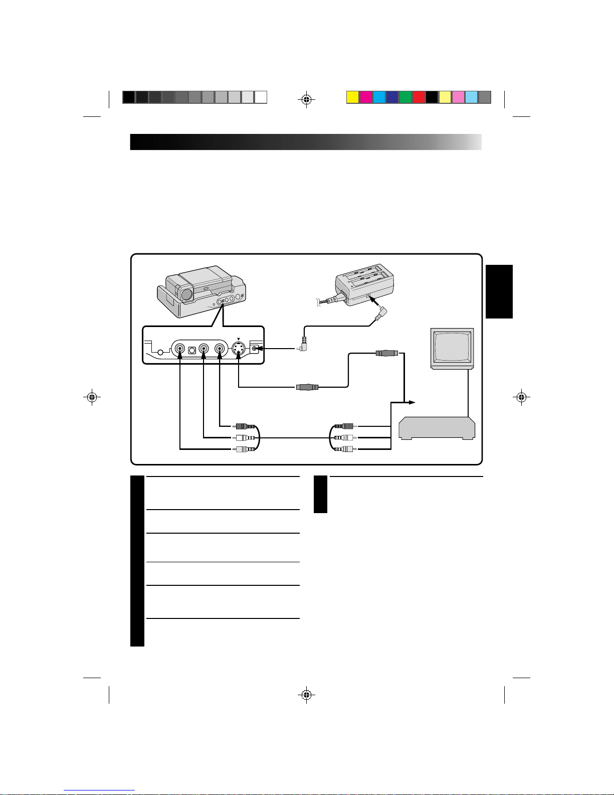
45
TV Playback
* Please refer to your VCR and/or TV instruction manual(s) when connecting.
NOTES:
●
If feedback or howling occurs during TV Playback, move the Docking Station so the camcorder’s microphone is
away from the TV, or turn down the TV’s volume.
●
If RECORD/STANDBY (Pause) is engaged for 5 minutes, the Stop mode is automatically activated to protect the
heads.
●
During playback, if the camcorder is left on its side for an extended period, its surface will become very warm. It
is recommended that you use the Docking Station (
Z
pg. 44) or the CAM Stand (Z pg. 12) during playback.
1
CONNECT DOCKING STATION TO
TV OR VCR
Connect as shown in the illustration.
2
TURN ON POWER
Turn on the power to the camcorder and the TV/VCR.
3
SELECT TV’S VIDEO MODE
Set the TV to the channel or mode appropriate for
video playback.
If Using A VCR
. . . go to step 4.
If not
. . . go to step 5.
4
CONNECT VCR OUTPUT TO TV
INPUT
Refer to your VCR’s instruction manual.
5
START PLAYBACK
Press PLAY. You can watch the scenes you recorded
on the TV.
6
END PLAYBACK
Press STOP and, if you’re not going to
continue using the camcorder, set the Power
Dial to “OFF”.
NOTES:
●
If, when using an S-Video cable, there’s no
picture, connect the camcorder’s output to the
regular video input on the TV or VCR and try
again.
●
To change from normal to slow-motion playback,
press PAUSE, then point the remote control at the
Docking Station and press SLOW. After playing
back in slow motion for about 20 seconds,
normal playback resumes. To stop slow-motion
playback in progress, press PLAY.
●
During slow-motion playback, due to digital
image processing, the picture may take on a
mosaic effect.
WHITE
YELLOW
YELLOW
TO AUDIO INPUT
JACKS (L/R)
TO AUDIO OUTPUT
JACKS (L/R)
TO S-VIDEO OUTPUT JACK
TO DC INPUT
JACK
When an
S-Video jack
is available.
DC CORD
RED
TO VIDEO OUTPUT
JACK
RED
WHITE
AUDIO and
VIDEO cable
AC POWER
ADAPTER/CHARGER
TO DC OUTPUT
JACK
S-VIDEO
CABLE
TO S-VIDEO
INPUT JACK
TO VIDEO INPUT JACK
Connect to AV
jack-equipped
TV or to VCR.
VCR (Recording deck)

46
VCR/TV Connection
MIC
AV-OUT
DC-IN 6V
A
B
a
b
c
C
1
CONNECT CAMCORDER TO TV OR
VCR
Connect as shown in the illustration.
2
ATTACH CAM STAND TO
CAMCORDER
Line up A with a, B with b and C with c.
The CAM Stand has two sides. One side is
used to hold the camcorder upright and the
other side is used to hold the camcorder flat.
3
TURN ON POWER
Turn on the power to the camcorder and the
TV/VCR.
4
SELECT TV’S VIDEO MODE
Set the TV to the channel or mode appropriate
for video playback.
If Using A VCR . . . go to step 4.
If not . . . go to step 5.
5
CONNECT VCR OUTPUT TO TV
INPUT
Refer to your VCR’s instruction manual.
6
START PLAYBACK
Slide the cover (Z pg. 47) and press PLAY.
You can watch the scenes you recorded on the
TV.
7
END PLAYBACK
Press STOP and, if you’re not going to
continue using the camcorder, set the Power
pDial to “OFF”.
NOTES:
To choose whether or not the following displays
appear on the connected TV . . .
●
Date/Time, Time Code
..... set to “ON” or “OFF” in the Playback Menu
(Z pg. 49).
●
Playback Sound Mode Display
..... set the Power Dial to “REC”, and set “ON
SCREEN” in the Date/Time Menu (Z pg. 30)
to “ON” or “OFF”. Then set the Power Dial
back to “PLAY”.
CAM STAND
To AV OUT
AUDIO and VIDEO cable
(ø3.5 DV TV or VCR)
To AUDIO
and VIDEO IN
connectors
PLAYBACK
Basic Connections (Cont.)

47
OFF
5S
REC
PLAY
PLAY
/PAUSE
REW
RE SHOOT
You can watch what you’ve recorded in the viewfinder.
NOTES:
●
You can also perform a High-Speed Search by
pressing and holding REW or FF during the PLAY
mode. The search continues as long as you hold
the button. Once you release it, normal playback
resumes.
●
A slight mosaic effect appears on screen during
High-Speed Search. This is not a malfunction.
●
The sound is not available during High-Speed
Search.
Still Playback
To temporarily stop playback, press PAUSE. Press
again to resume playback. If still playback
continues for more than about 3 minutes, the
camcorder’s Stop mode is automatically engaged.
After 5 minutes in the stop mode, the camcorder’s
power is automatically turned off.
1
SELECT MODE
Pull out the viewfinder and set the Power Dial
to “PLAY”.
2
OPEN COVER
Slide the camcorder’s Operation Panel cover
as shown in the illustration.
3
REWIND TAPE
Press REW. If you rewind all the way to the end
of the tape, it stops automatically.
4
WATCH RECORDING
Press PLAY. You can watch the recording in the
viewfinder.
3
5
END PLAYBACK
Press STOP and set the Power Dial to “OFF”.
To Perform High-Speed Search . . .
..... press REW or FF after pressing PLAY. The tape
will move at approximately 9 times the normal
playback speed. Watch in the viewfinder and,
when you reach the spot you want to see, press
PLAY and normal playback resumes.
POWER DIAL
PLAYBACK
Basic Playback
POWER
LAMP
OPERATION PANEL
COVER

48
T
W
48
kHz
MODE
32
kHz
MODE
SYNCHRO
DISPLAY
T I ME CODE
END
FULL SOUND
SOUND
1
0.0
ON
OFF
ITEM ZOOM SW .
SET SET BUTTON
48
kHz
MODE
32
kHz
MODE
SY NC HR O
DISPLAY
T I ME CODE
END
FULL SOUND
SOUND
1
0.0
ON
OFF
ITEM ZOOM SW.
SET SET BUTTON
Playback Menu
The Playback Menu allows you to set the following functions:
Playback Sound (48 kHz, 32 kHz), Synchro
Comp, Display
and
Time Code
. The following procedure applies to all except
Synchro Comp
(Z pgs. 57–58).
3
SET FUNCTION PARAMETERS
Slide the Zoom Lever to cycle through the
available settings for the selected function, and
stop when the desired setting appears. Then
press SET, and the pointer automatically moves
to “END”.
•To set parameters for other functions, repeat
steps 2 and 3.
4
CLOSE MENU
Press SET again, and the menu disappears.
1
ACCESS PLAYBACK MENU
Press MENU. The Playback Menu appears in
the viewfinder and on the connected TV.
2
SELECT FUNCTION
Place the pointer next to the desired function
by sliding the Zoom Lever, then press SET. The
pointer stops blinking, indicating that the
function has been selected.
POWER DIAL
ZOOM LEVER
MENU BUTTON
SET BUTTON
PLAYBACK (Cont.)
ON
OFF
ON
OFF
PLAYBACK MENU
SOUND 2
SOUND 1
FULL SOUND

49
RECORDING SOUND DISPLAY OUTPUT SOUND
48 KHZz FULL SOUND Stereo sound
SOUND 1 “L” sound is output on both channels
SOUND 2 “R” sound is output on both channels
32 kHz FULL SOUND
SOUND 1 Stereo sound
SOUND 2
Playback Sound
During playback, the camcorder detects the sound mode in which the recording was made, and plays the
sound back. Select the type of sound to accompany your playback picture. (48 kHz is preset to “FULL
SOUND” and 32 kHz is preset to “SOUND 1”.)
When watching a tape recorded at 48 kHz, if you want to change the output sound, access the Playback
Menu and, in step 3 on page 48, select “48kHz MODE” and set it for “FULL SOUND”, “SOUND 1” or
“SOUND 2”. When playing back a tape recorded at 32kHz, set in the same manner. For information on
output sound during Audio Dubbing, see page 59.
NOTES:
●
You can also use the RM-V708U remote control’s AUDIO MONITOR Button to change the output sound
(without having to access the Playback Menu). Make sure you point the remote control at the Docking
Station’s sensor.
●
During playback, the camcorder detects the sound mode in which the recording was made. This detection
cannot be made during fast-forward or rewind.
Displaying The Time Code During
Playback
You can display the Time Code on screen during
playback. This is especially useful for editing. This
function is preset to “OFF”. To turn it on, select
“TIME CODE” at the Playback Menu and change
the setting.
ON– The Time Code is displayed on the playback
screen.
OFF– The Time Code doesn’t appear.
Displaying the Date During Playback
If the time has been set, the date is automatically
recorded separately from the recorded video signal.
You can display or remove the date anytime during
playback. This function is preset to “ON”. To turn it
off, select “DISPLAY” at the Playback Menu and
change the setting.
ON– The date is displayed on the playback screen.
OFF–The date is not displayed, or is removed.
12 : 34 : 29
DEC. 25 ’ 9 6
AM
10:35
VIEWFINDER
MINUTES
SECONDS
FRAMES*
*30 frames = 1 second

50
4
END ZOOM
Press and hold W until magnification returns to
normal. Or, press STOP and then press PLAY.
NOTES:
●
Zoom can also be used during slow-motion and
normal playback.
●
If the Video Echo effect (Z pg. 37) is selected,
pressing the ZOOM Buttons only cancels the
Video Echo effect.
1
FIND ‘ZOOM’ SCENE
Press PLAY to start playback, then press PAUSE
when you find the scene you want to magnify.
2
ACTIVATE ZOOM
Press ZOOM on the remote control. Make sure
the remote control is pointed at the Docking
Station’s sensor.
•Pressing T zooms in.
3
LOCATE PORTION OF MAGNIFIED
SCENE
You can move the image on screen around to
find a particular portion of the picture. While
holding down SHIFT, press § (LEFT),
© (RIGHT), ¶ (UP) and Ä (DOWN).
Playback Zoom
The recorded pictures can be magnified up to 10x at any time during playback.
PLAYBACK
Advanced Features
TW
Normal
playback
POWER DIAL
Press T
Press © (RIGHT)
to move image
REMOTE SENSOR
PLAY BUTTON
ZOOM BUTTONS
SHIFT BUTTON
LEFT/RIGHT/UP/
DOWN BUTTONS
STOP BUTTON
PAUSE BUTTON
RM-V708U (provided)

51
TW
OFF
1
2
3
4
5
CLASSIC F ILM
MONOTONE
SEPIA
STROBE
V I DEO ECHO
B/W
P . AE/EFFECT SELECT
1
START PLAYBACK
Press PLAY.
2
ACCESS PRODUCTION EFFECTS
MENU
Point the remote control at the Docking
Station’s sensor and press EFFECT. The
Production Effects Menu appears on the
connected TV.
3
SELECT EFFECT
Place the pointer next to the desired effect by
pressing EFFECT. After 2 seconds the menu
disappears and the selected function is
activated.
NOTE:
To deactivate the selected effect, press
EFFECT ON/OFF on the remote control.
The effects that can be used during playback are
Classic Film, Monotone, Sepia, Strobe and Video
Echo
. The effects work the same in playback as they
did in recording. Refer to page 37 for more
information.
Playback Program AE/Effects
These effects allow you to be creative with the playback picture. You can use any one of the 5 effects.
POWER DIAL
EFFECT ON/OFF
BUTTON
P.AE EFFECT SELECT SCREEN
(Playback)
REMOTE SENSOR
PLAY BUTTON
RM-V708U (provided)
EFFECT
BUTTON

52
EDITING
Docking Station
Refer to “Docking Station Attachment” on pages 44 and 45 for attachment procedures. Make sure the
camcorder is attached to the Docking Station before beginning editing.
Dubbing
You can copy recorded scenes from the camcorder onto a videotape. Refer to your VCR’s instruction manual
for details.
5
END RECORDING
Press STOP to stop the source tape, and
engage the VCR’s stop mode.
NOTES:
●
You can use Playback Zoom (Z pg. 50) or
Playback P.AE/Effects (Z pg. 51) in step 2.
●
Before you start dubbing, make sure that the
viewfinder indications don’t appear on the
connected TV. If they do appear during dubbing,
they are being recorded onto the new tape.
To clear the Playback Sound Mode Display, press
DISPLAY on the RM-V708U Remote Control.
●
Select “DISPLAY” and “TIME CODE” from the
Playback Menu to show or hide the Date/Time
and the Time Code on the recording.
1
MAKE CONNECTIONS
Connect the Docking Station to your VCR as
shown in the illustration on page 45.
2
START PLAYBACK
Press PLAY to play back the source tape.
3
START RECORDING
While watching on the connected TV, engage
your VCR’s record mode from the spot on the
source tape you want to begin recording.
4
PAUSE RECORDING
Engage your VCR’s pause mode to stop
recording a segment.
POWER DIAL
STOP BUTTON
PLAY BUTTON
VCR (Recording deck)

53
TW
VCR BRAND
NAME
BUTTONS
(A) (B)
GE
1 1
9 2
9 `
9 4
MAGNAVOX
9 5
1 1
7 1
7 6
MITSUBISHI
6 7
6 8
NEC
3 7
3 8
PHILIPS
1 9
9 5
1 1
9 4
9 1
9 6
JVC A
B
C
9 1
9 6
9 3
HITACHI
6 6
6 3
VCR BRAND
NAME
BUTTONS
(A) (B)
PHILIPS
1 2
3 3
SANYO
3 6
3 5
SHARP
1 5
1 `
SONY
6 5
6 `
3 9
3 1
TOSHIBA
6 9
6 1
ZENITH
1 6
RCA
9 2
9 4
6 6
6 3
9 `
PANASONIC
1 3
1 7
1 1
9 4
1 8
VCR CODE LIST
3
1
6
789`
5
4
2
There are two types of signals:
A [ Operation Confirmation
When the VCR does not operate . . .
B [ Operation Confirmation
The following procedure explains how to set the
VCR brand.
NOTE:
Make sure the VCR’s power is off before beginning
the procedure.
1
PRESS AND HOLD SET BUTTON
Make sure the remote control is pointed at the
VCR.
2
ENTER BRAND
Press the appropriate brand setting button from
the VCR Code List.
3
RELEASE SET BUTTON
•Turn on the VCR’s power and make sure it is
operating properly.
•When the remote control’s battery expires,
reset the brand after installing a fresh battery.
Brand Setting
Before you can perform Automatic Dubbing, or control the VCR using the RM-V708U remote control, you
must set the VCR brand.
The remote control is capable of controlling basic VCR functions (PLAY, FF, REW, PAUSE, STOP). After
you’ve set the brand, point the remote at the VCR’s sensor and press the appropriate button.
*Some video decks cannot be controlled.
MBR SET
BUTTON
SHIFT
BUTTON
RM-V708U
(provided)
VCR (Recording deck)

54
TW
Random Assemble Editing
Using the RM-V708U remote control, you can use P.AE/Effects and make an original edited tape.
1
MAKE CONNECTIONS
Connect the Docking Station to your VCR and
make sure that the playback picture and sound
are available on the connected TV (Z pg. 45).
NOTES:
●
When using a JVC VCR with a remote pause
terminal, connect the editing jack on the Docking
Station to the VCR’s remote pause terminal using
an editing cable.
●
If the VCR has an S-Video input terminal, connect
it using an S-Video cable.
●
If the VCR has only one audio input terminal,
connect it using a conversion plug.
To Operate The VCR With The Remote Control . . .
..... press and hold SHIFT, then press the
appropriate control button.
NEW TAPE (VCR)
TO EDITING JACK
TO REMOTE PAUSE
JACK
EDITING CABLE
RM-V708U
TO S-VIDEO
OUTPUT JACK
TO S-VIDEO
INPUT JACK
TO AUDIO
INPUT JACKS (L/R)
SOURCE TAPE (Camcorder)
S-VIDEO CABLE
AUDIO and VIDEO cable
TO VIDEO INPUT JACK
TO AUDIO OUTPUT JACKS (L/R)
RED
WHITE
YELLOW
TO VIDEO OUTPUT JACK
RED
WHITE
YELLOW
2
START SOURCE PLAYBACK
Press PLAY and then press R.A. EDIT ON/OFF
on the remote control. Make sure to point the
remote control at the Docking Station's sensor.
•The Random Assemble Editing Menu appears
on the TV screen.
•If you're not using a Fade/Wipe at the
PROGRAM 1 Edit-In point, go to step 4.
3
EXECUTE FADE/WIPE IN
Press FADER/WIPE.
•Cycle through the effects by pressing
repeatedly, and stop when the one you want
is displayed.
•You can’t use a Picture Wipe/Dissolve at the
beginning of Program 1, or at the end of the
last scene.
EDITING (Cont.)
VCR (Recording deck)

55
1
2
3
4
5
6
7
8
T I ME CODE
TOT AL
00: 00
~
~
~
~
~
~
~
~
IN
OUT
: :
:
TW
NOTES:
●
When choosing a scene, set Edit-In and Edit-Out
points so there’s a relatively large difference
between them.
●
If the search time for an in-point exceeds
5 minutes, the recording deck's Record-Standby
mode will be cancelled and editing will not take
place.
●
If there are blank portions before or after the
Edit-In and Edit-Out points, a blue-backed screen
may be included in the edited version.
●
Since time codes register time only as accurately
as seconds, the time code total time may not
match the total program time exactly.
●
Turning off the camcorder’s power erases all
registered Edit-In and Edit-Out points.
●
To use a P. AE/Effect, press EFFECT on the remote
control repeatedly to cycle through the effects
until the one you want is displayed.
●
To change previously registered points, press
CANCEL on the remote control. The registered
points disappear, one at a time, from the most
recently registered point.
●
If you use Sepia or Monotone P.AE/Effects, you
can’t use the Dissolve or Black & White Fader. In
this case the Dissolve or Black & White indicator
begins blinking. Once the next Edit-In point is
registered, the effect is turned off. To combine
these effects, use Sepia or Monotone during
recording, then use Dissolve or Black & White
Fader during Random Assemble Editing.
CONTINUED ON NEXT PAGE
POWER DIAL
REMOTE SENSOR
PROGRAM
RANDOM ASSEMBLE
EDITING MENU
4
SET EDIT-IN POINT
At the beginning of the scene, press EDIT IN/
OUT on the remote control. The Edit In
position appears in the viewfinder and on the
connected TV.
5
SET EDIT-OUT POINT
At the end of the scene, press EDIT IN/OUT.
The Edit Out position appears in the viewfinder
and on the connected TV.
6
USE FADE WIPE ON SCENE
TRANSITION
Press FADE/WIPE.
•Cycle through the effects by pressing
repeatedly, and stop when the one you want
is displayed.
•If you select a Fade//Wipe effect for an
Edit-Out point, the effect is automatically
applied to the following Edit-In point.
•When you use Fade/Wipe effects, that time is
included in the total time (this does not apply
to Picture Wipe/Dissolve).
7
USE P.AE/EFFECT
Press EFFECT.
•Cycle through the effects by pressing
repeatedly, and stop when the one you want
is displayed.
•You can use Classic Film, Monotone, Sepia,
Strobe or Video Echo effects.
8
CONTINUE EDITING
Repeat steps 4 – 7.
•If you're not using Fade/Wipe or P.AE/Effects,
repeat steps 4 and 5 only.
PLAY BUTTON
R.A.EDIT ON/OFF BUTTON
FADER/WIPE BUTTON
EDIT IN/OUT BUTTON
EFFECT BUTTON
CANCEL BUTTON
RM-V708U (provided)

56
TW
1
2
3
4
5
6
7
8
T I ME CODE
015 :55
TOTAL
009: 02
00: 25 ~ 02: 05
07: 18 ~ 08:31
03: 33 ~ 05: 53
09: 30~13 : 15
15: 55 ~
~
~
~
P
B/W
P
IN
W
H
OUT
OFF
OFF
:
9
PREPARE SOURCE TAPE
Rewind the tape in the camcorder to the
beginning of the scene you want to edit and
press PAUSE.
10
ENGAGE VCR'S RECORD-PAUSE
MODE
Point the remote control toward the VCR's
infrared sensor and press VCR RECORD/
STANDBY, or manually engage the VCR's
Record-Pause mode.
11
START EDITING
Press EDIT on the Docking Station. Editing
proceeds as programmed, right through to the
end of the last registered scene.
•If you selected a Fade/Wipe effect, it is active
between selected scenes during dubbing.
•If you selected a P.AE/Effect, it is active
during scenes while dubbing.
•When dubbing is complete, the camcorder
enters the PAUSE mode, and the recorder
enters its RECORD/STANDBY mode.
•If you don’t register an Edit-Out point, the
tape will be dubbed all the way to the end
automatically.
12
STOP EDITING
Engage the STOP modes for the camcorder and
the recorder.
NOTES:
●
During dubbing, make sure the remote control is
pointed at the recorder’s sensor, and that the path
between the two is unobstructed.
●
If, during dubbing, you press a button on the
camcorder, its RECORD/STANDBY mode is
automatically engaged.
REW BUTTON
R.A.EDIT PROGRAM SCREEN
VCR RECORD/
STANDBY BUTTON
EDIT BUTTON
STOP BUTTON
FADE/WIPE BUTTON
EFFECT BUTTON
EDIT IN/OUT BUTTON
EDITING (Cont.)
RM-V708U
(provided)

57
3
PLAY BACK DUBBED SCENE
•If any images from the scene prior to the
transition you chose for your Edit-In point
were recorded, that means your VCR moves
quickly from RECORD/STANDBY to
RECORD.
•If the scene you tried to dub starts in
progress, the VCR is slow to start recording.
CONTINUED ON NEXT PAGE
For More Accurate Editing
Some VCRs make the transition from RECORD/STANDBY to RECORD mode faster than others. Even if you
begin editing for the camcorder and the VCR at exactly the same time, you may lose scenes you wanted, or
find that you’ve recorded scenes you didn’t want. For a cleanly edited tape, confirm and adjust the timing of
the camcorder against your VCR.
1
PREPARE FOR R.A. EDIT
Play back the tape in the camcorder, then point
the remote control at the Docking Station’s
sensor and press R.A. EDIT ON/OFF.
•”R.A. EDIT” appears on the TV screen.
2
CHOOSE A SCENE
Perform Random Assemble Editing on
PROGRAM 1 only. In order to check VCR and
camcorder timing, select the beginning of a
scene transition as your Edit-In point.
1
2
3
4
5
6
7
8
T I ME CODE
TOT AL
00 : 0 0
~
~
~
~
~
~
~
~
IN
OUT
: :
:
TW
REMOTE SENSOR
R.A.EDIT PROGRAM SCREEN
ON/OFF BUTTON
PROGRAM 1
RM-V708U
(provided)
VCR (Recording deck)

58
7
INPUT CORRECTION DATA
If the VCR is quick, slide the Zoom Lever
toward “–”; if the VCR is slow, slide toward
“+”. The adjustment range is from –1.3 to +1.3
seconds, in 0.1-second increments.
8
CLOSE MENU
Press SET twice.
•Now perform Random Assemble Editing
beginning with step 2 on page 54.
NOTE:
●
Depending on the recorder, there may be
situations where the timing difference cannot be
fully corrected.
4
SELECT OPERATION MODE
Set the Power Dial to “PLAY” and press PLAY.
5
ACCESS PLAYBACK MENU
Press MENU. The Playback Menu appears on
the TV screen.
6
SELECT FUNCTION
Place the pointer next to “SYNCHRO” by
sliding the Zoom Lever, then press SET. The
pointer stops blinking, indicating that the
function has been selected.
T
W
48
kHz
MODE
32
kHz
MODE
SYNCHRO
DISPLAY
T I ME CODE
END
FULL SOUND
SOUND
1
0.0
ON
OFF
ITEM ZOOM SW .
SET SET BUTTON
48
kHz
MODE
32
kHz
MODE
SYNCHRO
DISPLAY
T I ME CODE
END
FULL SOUND
SOUND
1
–0.1
ON
OFF
ITEM ZOOM SW .
SET SET BUTTON
SET BUTTON
MENU BUTTON
POWER DIAL
ZOOM LEVER
PLAYBACK MENU
STOP BUTTON
PLAY BUTTON
EDITING (Cont.)
VCR (Recording deck)

59
Audio Dubbing
Using a tape recorded at 32 kHz, you can customize the soundtrack of a tape you’ve recorded.
NOTE:
Audio Dubbing is not possible on a tape recorded at 48 kHz.
4
PAUSE DURING DUBBING
Press PAUSE.
5
STOP DUBBING
Press STOP.
NOTES:
●
When editing onto a tape that was recorded at 32
kHz, the old and new soundtracks are recorded
separately.
●
To select the desired sound for playback, press
AUDIO MONITOR on the remote control.
●
If you dub onto a blank space on the tape, the
sound may be disrupted. Make sure you only edit
recorded areas.
●
If you change from 32 kHz to 48 kHz in midrecording and then use the tape for Audio
Dubbing, it is not effective from the point where
48 kHz recording began.
1
FIND EDIT-IN POINT
Play back the tape to locate the point where
editing will start, then press PAUSE.
2
CONNECT EXTERNAL
MICROPHONE
Connect an optional stereo microphone. Then
while holding A. DUB on the remote control,
press PAUSE.
•Pull out the viewfinder and “6e” appears.
•Press DISPLAY on the remote control if
sending the image to a connected TV.
3
BEGIN DUBBING
Press PLAY, then begin “narrating” using the
external microphone.
6e
TW
POWER DIAL
REMOTE SENSOR
AUDIO DUB STANDBY
A.DUB BUTTON
PLAY BUTTON
PAUSE BUTTON
EXT. MIC INPUT
CONNECTOR
DISPLAY BUTTON
STOP BUTTON
AUDIO MONITOR
BUTTON
RM-V708U (provided)
RECORDING SOUND DISPLAY OUTPUT SOUND
32 kHz FULL SOUND Original and new tracks are combined and output in stereo.
SOUND 1 Original track is output on both "L" and "R" channels in stereo.
SOUND 2 New track is output on both "L" and "R" channels in stereo.

60
6w
TW
12:34
Insert Editing
You can insert snapshots and other scenes in previously recorded footage.
4
START RECORDING
Press RECORDING START/STOP to begin
editing.
•Confirm the insert at the time code you
checked in step 1.
5
PAUSE DURING EDITING
Press RECORDING START/STOP. Press again
to resume editing.
6
STOP EDITING
Press RECORDING START/STOP, then press
STOP.
NOTES:
●
When performing Insert Editing, the tape’s Video
Area and Sub-Code Area (Z pg. 7) are rewritten,
so the date and time information changes.
●
If you perform Insert Editing onto a blank space
on the tape, the audio and video may be
disrupted. Make sure you only edit recorded
areas.
1
FIND EDIT OUT POINT
Confirm the time code at this point.
(Z pg. 49)
2
FIND EDIT IN POINT
Press REW until the point is located, then press
PAUSE.
3
PREPARE FOR INSERT EDITING
Press and hold INSERT on the remote control,
then press PAUSE. “6w” and the Time Code
(min.:sec.) appear in the viewfinder.
NOTE:
●
To see the on-screen characters on a connected
TV, press DISPLAY on the remote control.
(Z pg. 52)
POWER DIAL
REMOTE SENSOR
DISPLAY BUTTON
PLAY BUTTON
PAUSE BUTTON
RECORDING START/STOP
BUTTON
INSERT BUTTON
EDITING (Cont.)
REW(IND) BUTTON
RM-V708U (provided)

61
TROUBLESHOOTING
SYMPTOM POSSIBLE CAUSES CORRECTIVE ACTION
1.
No power is supplied.
2.
Recording cannot be
performed.
3.
There is no playback
picture.
4.
Some functions are not
available.
5.
The focus does not adjust
automatically.
6.
The cassette won’t load
properly.
7.
Play, Rewind and
Fast-Forward functions
don’t work.
8.
The tape is moving, but
there’s no picture.
9.
When shooting a subject
illuminated by bright
light, vertical lines appear.
10.
In the 5-Second mode,
recording ends before 5
seconds have elapsed.
11.
Even though “GAIN UP”
was set to “
A
”, scenes
shot in dark places are
not brightened.
12.
Snapshot mode cannot be
used.
1.
•The power is not connected
properly.
•The battery is dead.
•The viewfinder hasn’t been
pulled out.
2.
•The tape’s record safety tab
is set to “SAVE”.
•The Power Dial is set to
“PLAY”.
3.
•The camcorder is not getting
power, or some other
malfunction exists.
•The lens cover is closed.
4.
•The Select Dial is set to
“AUTO”.
•The Power Dial is set to “5S”.
5.
•Focus is set to “MANUAL”.
•The recording was done in a
dark place, or the contrast
was low.
•The diopter is not properly
adjusted.
•The lens is dirty or covered
with condensation.
6.
•The cassette is in the wrong
position.
•The battery’s charge is low.
7.
•The Power Dial is not set to
“PLAY”.
•The cassette’s cover is open.
8.
•Your TV has AV input
terminals, but is not set to
its VIDEO mode.
9.
•This is a result of
exceedingly high contrast,
and is not a malfunction.
10.
•The 5-Second mode in the
System Menu is set to
“ANIMATION”.
11.
•Depending on the light source,
the 1/30 shutter speed may be
deactivated in order to reduce
the shakiness in the picture.
12.
•P.AE/Effects Sepia,
Monotone or Slow (Slow
Shutter) are activated.
•The Squeeze mode is
selected.
•The Cinema mode is engaged,
disabling the white border.
1.
•Connect the AC Adapter
securely (
Z pg. 12).
•Replace the dead battery
with a fully charged one
(
Z pg. 11).
•Pull the viewfinder out.
2.
•Set the tape’s record safety
tab to “REC” (
Z pg. 15).
•Set the Power Dial to
“REC”.
3.
•Turn the camcorder’s power
off and on again.
•Pull out the viewfinder to
open the lens cover.
4.
•Set the Select Dial to any
position except “AUTO”.
•Set the Power Dial to any
position except “5S”.
5.
•Set Focus to “AUTO”
(
Z pg. 39).
•Adjust the diopter
(
Z pg. 16).
•Clean the lens and check
the focus again.
6.
•Set it in the right position.
•Install a fully charged
battery.
7.
•Set the Power Dial to
“PLAY”.
8.
•Set the TV to the mode or
channel appropriate for
video playback.
9.
————
10.
•Select “5S” or “5SD” in the
System Menu.
11.
————
12.
•Disengage them.
•Disengage the Squeeze
mode.
•Disengage the Cinema
mode.
If, after following the steps in the chart below, the problem still exists, please consult your nearest JVC
dealer or Technical Service Center.

62
SYMPTOM POSSIBLE CAUSES CORRECTIVE ACTION
13.
Digital Zoom doesn’t
work.
14.
P.AE/Effects and Fade/
Wipe Effects don’t work.
15.
The Black & White Fader
doesn’t work.
16.
The Dissolve function
doesn’t work.
17.
The Picture Wipe and
Dissolve functions don’t
work.
13.
•10X optical zoom is selected.
•
The Video Echo effect is activated.
•Picture Wipe or Dissolve
are being used in a scene
transition.
•5-Second recording was
done with the Power Dial
set to “5S”, and with “5SD”
selected in the System Menu.
•Snapshot Dissolve was
attempted during Digital
Zoom.
14.
•The Select Dial is set to
“AUTO”.
•The Power Dial is set to
“5S”.
15.
•The Sepia or Monotone
effects are activated.
16.
•P.AE/Effects Sepia,
Monotone or Slow are
activated.
•The Squeeze mode is
selected.
17.
•The last selected editing
scene is ending.
•At the end of the last
selected scene for editing,
the Power Dial was set to
“OFF”.
•The power is off.
•The previously selected
P.AE/Effect was changed
after the last selected scene
for editing was registered.
•The P.AE/Effects in the
Recording Menu were
exchanged after the last
selected scene for editing
was registered.
TROUBLESHOOTING (Cont.)
13.
•Turn off the Video Echo
effect.
•Wait until the Picture Wipe
or Dissolve effects are
completed.
•Change the setting of either
the System Menu or the
Power Dial.
•Do not attempt to take a
Snapshot when performing
Digital Zoom.
14.
•Set the Select Dial to
“MANUAL”.
•Change the setting of the
Power Dial.
15.
•Turn off Sepia and
Monotone.
16.
•Turn off Sepia and
Monotone before adding
Dissolve to a scene
transition.
•Make sure that the Squeeze
mode in the Recording
Menu is set to “OFF”.
17.
• Select Picture Wipe or
Dissolve before beginning
recording. The effects are
then automatically
activated.
•Do not turn off the
camcorder’s power after
setting Edit-In and Edit-Out
points, as they will all be
erased.
•The camcorder
automatically shuts off
after 5 minutes have
elapsed in the RECORD/
STANDBY mode. Make
sure you continue
operations within
5 minutes after engaging
RECORD/STANDBY.
•Make sure you have
selected the P.AE/Effects
you want before starting
editing.
•Exchanging P.AE/Effects
may deactivate the effect(s)
you selected. Once you’ve
selected an effect, do not
perform an exchange
before beginning editing. If
you do, make sure you
don’t replace the effect(s)
you selected.

63
SYMPTOM POSSIBLE CAUSES CORRECTIVE ACTION
18.
The Picture Wipe function
doesn’t work.
19.
Even when Slow (Slow
Shutter) isn't selected, the
image looks like it is
activated.
20.
The Video Echo effect
doesn’t work.
21.
There is no strobe when
the Classic Film and
Strobe effects are
activated.
22.
White Balance cannot be
activated.
23.
The viewfinder indications blink.
24.
There are disturbances in
audio and video.
25.
An unusual mark appears
in the viewfinder.
26.
An error indication
(E01 — E07) appears in
the viewfinder.
18.
•The Slow (Slow Shutter)
effect is activated.
•The Squeeze or Cinema
mode is selected in the
Recording Menu.
19.
•When shooting in the dark
with GAIN UP set to
A
, the
unit becomes highly sensitive
to light and the image takes
on an effect similar to Slow
(Slow Shutter).
20.
•The Picture Wipe or
Dissolve functions are in use.
•The Squeeze mode is
selected in the Recording
Menu.
•Snapshot Dissolve is in
progress.
•A Fade-In or Fade-Out is in
progress (White Fader, Black
Fader or Black & White
Fader).
21.
•The Picture Wipe or
Dissolve functions are in
use.
•Snapshot Dissolve is in
progress.
22.
•The Sepia or Monotone
effects are activated.
•Snapshot Dissolve is in
progress.
23.
•Certain FADE/WIPE, P.AE/
Effects and other functions
that cannot be used together
are selected at the same
time.
24.
•If Audio Dubbing or Insert
Editing have been performed
repeatedly on the same
portion of the tape,
disturbance to the sound
and picture may result.
25.
————
26.
•A malfunction of some kind
has occurred. In this case
the camcorder’s functions
become unusable.
18.
•Make sure the Squeeze
mode, Cinema mode, or
Slow effect is not activated
when preparing to use the
Picture Wipe function.
19.
•If you want the lighting to
look more natural, set
GAIN UP to "AGC" or
"OFF" in the Recording
Menu.
20.
•Make sure the Squeeze
mode is set to “OFF”.
•Do not try to use the Video
Echo effect during a
Fade-In or Fade-Out.
21.
•Do not try to use the
Classic Film or Strobe
effects during a scene
transition.
22.
•Turn off Sepia or Monotone
before setting White
Balance.
•Wait until the Snapshot
Dissolve is finished before
setting White Balance.
23.
•Re-read the sections
covering FADE/WIPE and
P.AE/Effects
(
Z pg. 31, 36).
24.
•Use a new, or infrequently
used, tape for Audio
Dubbing and Insert Editing.
25.
•Check the section of the
manual that explains
viewfinder indications
(Z pg. 66).
26.
•Remove the tape or the
battery pack, and wait a
few minutes for the
indication to clear. When it
does, you can resume using
the camcorder.
If the indication remains,
please consult your nearest
JVC dealer or Technical
Service Center.

64
7
RESET VIEWFINDER
Close the viewfinder's cover and push the
viewfinder back in.
8
CLOSE CASSETTE DOOR
Audio/Video Cable And CAM Stand
1
WRAP CABLE AROUND STAND
Position the plug of the Audio/Video cable
(ø3.5 DV TV or VCR) as shown in the
illustration, then wrap the cable around the
stand in the direction indicated.
2
CONFIRM PLUG POSITION
Make sure the white, red and yelow plugs are
positioned as shown in the illustration.
Cleaning The Camcorder
1
CLEAN EXTERIOR
Wipe gently with a soft cloth.
2
CLEAN LENS
Blow it with a blower brush, then wipe gently
with lens cleaning paper.
3
REMOVE POWER SUPPLY
Remove the battery pack or disconnect the AC
Power Adapter/Charger.
4
OPEN CASSETTE DOOR
There is no power to the camcorder, so the
cassette holder won't open.
5
PULL OUT VIEWFINDER
Pull out the viewfinder and slide its cover
open.
6
CLEAN VIEWFINDER
Remove dust using a blower brush.
CASSETTE HOLDER
BATTERY PACK
AFTER USE
Audio/Video cable (ø3.5 DV TV or VCR)
CASSETTE DOOR
VIEWFINDER COVER
CAM STAND

65
@
0
!
%^
&
*
(
)
e
t
y r
wq
#
$
1
2
3
4
5
6
7
8
9
CONTROLS, INDICATIONS AND CONNECTORS
Main Unit
@ Remaining Battery Power Indicator
# “No Tape Loaded” Indicator
$ Tape Advance Buttons (Z pg. 24)
% Stereo Microphone
^ Power Lamp (Z pg. 23)
& OPEN/EJECT Switch (Z pg. 15)
* Zoom Lever (Z pg. 14)
( Select Dial (Z pg. 18)
) SET Button (Z pg. 19)
q Battery Cover (Z pg. 11)
w RECORDING START/STOP Button (Z pg. 23)
e Power Dial (Z pg. 14)
r Diopter Adjust Lever (Z pg. 16)
t Tripod Mounting Socket
y Hand Strap Eyelet (Z pg. 16)
1 MENU Button (Z pg. 19)
2 White Balance Sensor
* Take care not to cover the sensor with your
hand while shooting.
3 Lens
4 Tally Lamp
5 SNAPSHOT Button (Z pg. 25)
6 Ext. Mic Input Jack (Z pg. 12)
7 AV Output Jack (Z pg. 12)
8 DC Input Jack (Z pg. 12)
9 Multi Connector
* Located inside the cover. Connect to the
Docking Station’s multi connector.
0 LCD Display Window
! Remaining Tape Time (during recording)
Time Code (during playback)
(Lights)
Fullly
charged
2/3 Charge
Remaining
1/3 Charge
Remaining
No Charge
Remaining
STOP
BUTTON
PLAY BUTTON
PAUSE BUTTON
FF BUTTON
CAN. BUTTON
REW BUTTON
RE SHOOT BUTTON
Battery Pack Remaining Power Indicator changes as follows
according to the battery pack’s remaining power level:
When the power is almost gone, the indicator blinks, then the
unit shuts off. Replace the battery pack with a fully charged one.

66
Viewfinder Indications
No. NAME & FUNCTION
$
“No Tape Loaded” Indicator
Appears for 15 seconds after power is turned on
if there's no tape loaded.
% Clock Battery Warning
Appears when the clock (lithium) battery is not
in place or exhausted. For inserting or replacing
the clock battery, refer to page 13.
^ Wind Cut Indicator (Z pg. 22)
& Date/Time Display (Z pg. 14)
* Recording Mode Indicator (Z pg. 27)
( Sound Mode Display (Z pg. 22)
) Time Code Display (Z pg. 29)
q Snapshot Indicator (Z pg. 25)
w Self-Timer Indicator (Z pg. 28)
e Focus Indicators (Z pg. 39)
r White Balance Indicator (Z pg. 42)
t Exposure Indicator (Z pg. 40)
y Iris Lock Indicator (Z pg. 41)
u Zoom Level Indicator (Z pg. 26)
i FADE/WIPE Indicator (Z pg. 31)
o P.AE/Effect Indicator (Z pg. 36)
p Playback Sound Mode Display (Z pg. 49)
— “Tape End” Indicator (Z pg. 24)
— An error number (E01, etc.)
appears in the viewfinder (Z pg. 64)
Consult your nearest JVC dealer.
No. NAME & FUNCTION
1 Select Dial Position (Z pg. 18)
2 GAIN UP Indicator (Z pg. 20)
3 Wide Mode (Z pg. 20)
4 “Battery Low” Indicator
Appears and blinks when battery charge is low.
5 Digital Image Stabilizer Indicator
(Z pg. 20)
6 Record-Standby Indicator (Z pg. 27)
7 “Cassette Loaded” Indicator
Appears when no tape is loaded, or when you
try to record with the record safety tab set to
“SAVE”.
8 Condensation Warning
When this indicator appears, all functions are
disabled. Turn the unit off for a few hours, and
when you turn it on again the indicator should
disappear.
9 Tape Remaining Indicator (Z pg. 24)
0 Recording Indicator (Z pg. 23)
! “Tape Running” Indicator (Z pg. 23)
@ Audio Dubbing/Insert Editing Mode
Indicator (Z pgs. 59, 60)
# Head clog warning
At the start of recording, appears and
blinks if dirt is detected on heads. Stop
recording and clean the heads using the
Cleaning Cassette. (
Z pg. 69)
Recording And Playback
D
T
W
48
kHz
/F ULL
12345678
9
0
!
@
#
$
%
^
&
*()qw
e
r
u
t
y
o
p
PHOTO
REC
TAPE!
30min
DEC
25’ 96
AM
10:35
F . AUTO
PAUSE
MODE
5 SD
SOUND
32kHz
6we
1
P
L
00:00:00
0
A
i
CONTROLS, INDICATIONS AND CONNECTORS (Cont.)

67
Docking Station
@ Remote Control Sensor ..................... (Z pg. 50)
# JLIP Jack (Joint Level Interface Protocol)
In the future, it will be used to connect the
camcorder to a device such as a personal
computer.
$ Video Output Jack ............................ (Z pg. 45)
% Multi Jack ......................................... (Z pg. 44)
^ Audio Output Jack [L] ...................... (Z pg. 45)
& DC Input Jack ................................... (Z pg. 45)
* S-Video Output Jack ......................... (Z pg. 45)
( Audio Output Jack [R] ...................... (Z pg. 45)
) DC Output Jack
For future use.
1 Fan
Comes on automatically when camcorder is
attached; serves to cool the unit down. Take care
not to interfere with the blades.
2 EDIT Button ...................................... (Z pg. 56)
3 CHARGE Indicator ........................... (Z pg. 44)
4 PAUSE Button
5 PLAY Button ..................................... (Z pg. 50)
6 RELEASE Button ................................ (Z pg. 44)
7 Lock Lever ........................................ (Z pg. 44)
8 Fast-Forward (FF) Button
9 Rewind (REW) Button ....................... (Z pg. 56)
0 STOP Button ..................................... (Z pg. 52)
! EDIT Jack .......................................... (Z pg. 54)
12345 6
@! 098 7
#$%^ &
)(*

68
Battery Packs
The supplied battery pack is a lithium-ion battery.
Before using the supplied battery pack or an
optional battery pack, be sure to read the following
cautions:
1. To avoid hazard . . .
.... do not burn.
.... do not short-circuit the terminals.
.... do not modify or disassemble.
.... use only specified chargers.
2. To prevent damage and prolong service
life . . .
.... do not subject to unnecessary shock.
.... charge in an environment where
temperatures are within the tolerances shown
in the chart below. This is a chemical
reaction type battery—cooler temperatures
impede chemical reaction, while warmer
temperatures can prevent complete charging.
.... store in a cool, dry place. Extended exposure
to high temperatures will increase natural
discharge and shorten service life.
.... avoid prolonged uncharged storage.
.... remove from charger or powered unit when
not in use, as some machines use current
even when switched off.
3. To prevent damage to the camcorder . . .
.... replace the battery pack when it begins to
deliver less recording time per charge.
NOTE:
It is normal for the battery pack to be warm after
charging, or after use.
Temperature Range Specifications
Charging ................................... 10°C to 35°C
Operation ................................. 10°C to 40°C
Storage...................................... –10°C to 30°C
NOTES:
●
Recharging time is based on room temperature of
20°C.
●
The lower the temperature, the longer recharging
takes.
CAUTIONS
When using the AC Power Adapter/Charger in
areas other than the USA
n The provided AC Power Adapter/Charger features
automatic voltage selection in the AC range from
110 V to 240 V.
USING HOUSEHOLD AC PLUG ADAPTER
In case of connecting the unit's power cord to an
AC wall outlet other than American National
Standard C73 series type use an AC plug adapter,
called a "Siemens Plug", as shown.
For this AC plug adapter, consult your nearest JVC
dealer.
Plug adapter
INFORMATION
This device complies with Part 15 of FCC Rules.
Operation is subject to the following two
conditions:
(1) This device may not cause harmful interference,
and (2) this device must accept any interference
received, including interference that may cause
undesired operation. Change or modifications not
approved by the party responsible for compliance
could void the user's authority to operate the
equipment. This equipment has been tested and
found to comply with the limits for a Class B digital
device, pursuant to Part 15 of the FCC Rules. These
limits are designed to provide reasonable protection
against harmful interference in a residential
installation. This equipment generates, uses, and
can radiate radio frequency energy and, if not
installed and used in accordance with the
instructions, may cause harmful interference to
radio communications. However, there is no
guarantee that interference will not occur in a
particular installation. If this equipment does cause
harmful interference to radio or television reception,
which can be determined by turning the equipment
off and on, the user is encouraged to try to correct
the interference by one or more of the following
measures:
Reorient or relocate the receiving antenna.
Increase the separation between the equipment
and receiver.
Connect the equipment into an outlet on a circuit
different from that to which the receiver is
connected.
Consult the dealer or an experienced radio/TV
technician for help.
Battery
Terminals
Cap

69
Cassettes
To properly use and store your cassettes, be sure to
read the following cautions:
1. During use . . .
.... make sure the cassette bears the Mini DV
mark.
.... be aware that recording onto prerecorded
tapes automatically erases the previously
recorded video and audio signals.
.... make sure the cassette is positioned properly
when inserting.
.... do not load and unload the cassette
repeatedly without allowing the tape to run
at all. This slackens the tape and can result in
damage.
.... do not open the front tape cover. This
exposes the tape to fingerprints and dust.
2. Store cassettes . . .
.... away from heaters or other heat sources.
.... out of direct sunlight.
where they won’t be subject to unnecessary
shock or vibration.
.... where they won’t be exposed to strong
magnetic fields (such as those generated by
motors, transformers or magnets).
.... vertically, in their original cases.
Main Unit
1. For safety, DO NOT . . .
.... open the camcorder’s chassis.
.... disassemble or modify the unit.
.... short-circuit the terminals of the battery pack.
Keep it away from metallic objects when not
in use.
.... allow inflammables, water or metallic objects
to enter the unit.
.... remove the battery pack or disconnect the
power supply while the power is on.
.... leave the battery pack attached when the
camcorder is not in use.
2. Avoid using the unit . . .
.... in places subject to excessive humidity or
dust.
.... in places subject to soot or steam such as
near a cooking stove.
.... in places subject to excessive shock or
vibration.
.... near a television set.
.... near appliances generating strong magnetic
or electric fields (speakers, broadcasting
antennas, etc.).
.... in places subject to extremely high (over
40°C or 104°F) or extremely low (under 0°C
or 32°F) temperatures.
3. DO NOT leave the unit . . .
.... in places of over 50°C (122°F).
.... in places where humidity is extremely low
(below 35%) or extremely high (above 80%).
.... in direct sunlight.
.... in a closed car in summer.
.... near a heater.
4. To protect the unit, DO NOT . . .
.... allow it to become wet.
.... drop the unit or strike it against hard objects.
.... subject it to shock or excessive vibration
during transportation.
.... keep the lens directed at extremely bright
objects for long periods.
.... direct the eyepiece of the viewfinder at the
sun.
.... carry it by holding the viewfinder.
.... swing it excessively when using the shoulder
strap.
5. Dirty heads can cause the folowing
problems:
•No picture during
playback.
•Blocks of noise appear
during playback.
•During recording, the
Head Clog Warning
indicator “ ” appears in the viewfinder.
In such cases, use the optional Cleaning Cassette
M-DV2CL. Insert it and play back for approximately 20 seconds. After this time the camcorder
stops automatically. If the cassette is used more
than once consecutively, damage to the video
heads may result.
If, after using the Cleaning Cassette, the
problems still exist, consult your nearest JVC
dealer.
About moisture condensation . . .
•You have observed that pouring a cold liquid into
a glass will cause drops of water to form on the
glass‘ outer surface. This same phenomenon
occurs on the head drum of a camcorder when it
is moved from a cool place to a warm place, after
heating a cold room, under extremely humid
conditions or in a place directly subjected to the
cool air from an air conditioner.
•Moisture on the head drum can cause severe
damage to the video tape, and can lead to internal
damage to the camcorder itself.
Serious malfunctioning
If malfunctioning occurs, stop using the unit
immediately and consult your local JVC dealer.

70
SPECIFICATIONS
MAIN UNIT
General
Power : DC 6 V (using AC Adapter) DC 3.6 V (using Battery)
Power consumption : 6.2 W
Format : DV Format (SD mode)
Signal format : NTSC Standard
Video signal recording format : Digital Component Recording
Data compression rate : 25 Mbps
Digital compression technology : DCT (Discrete Cosine Transform) &
VLC (Variable Length Coding)
Cassette : MINI DV Cassette
Tape Speed : 18.8 mm/sec.
Maximum recording time : 60 min. (using DVM-60 cassette)
Continuous recoring time : Approx. 30 min.
(using fully charged BN-V712U
Battery Pack)
Fast-Forward/Rewind Time : Approx. 90 sec. (using DVM-60 cassette)
Pickup : 1/3" CCD (single) 570,000 pixels
(recording area approx. 330,000 pixels)
Zoom : 10x Optical Zoom 20x/100x Digital Zoom
Lens diameter : F1.6, f = 4.5` 45 mm
(Filter Diameter) ø27
Viewfinder : Electronic 0.55" color LCD
White balance : AUTO/MAN.
Iris : AUTO/LOCK
Microphone : Condensor type/stereo
Operating temperature : 0 — 40°C
Operating humidity : 35 — 80%
Storage temperature : –20 — 50°C
Dimensions : 43 (W) x 148 (H) x 88 (D) mm
(1-3/4" x 5-7/8" x 3-1/2")
Weight : Main unit 450 g
During recording (With BN-V712U Battery Pack,
Cassette M-DVM30ME, Hand Strap) 520 g
Audio
Sampling frequencies : 48 kHz, 44.1 kHz (playback), 32 kHz
Channels : 2 (48 kHz)
4 (32 kHz)
Quantum Bits : 16 straight (48 kHz)
12 straight (32 kHz)
Connectors
Microphone input connector : ø3.5 mm –62 dB stereo
A/V output connector : ø3.5 mm 4 quadripolar (analog output)
DC input connector :6 V
Multi connector : 34 pin
*
Design and specifications subject to change without notice.

71
Battery Pack BN-V712U
Power : 3.6 V/1.250mAh
Dimensions : 20 mm (W) x 20 mm (H) x 71 mm (D)
(4/5" x 4/5" x 2–4/5")
Weight : Approx. 50 g
Remote Control Unit RM-V708U
Power : DC 3 V (Lithium Battery CR2025)
Battery Life : Approx. 1 year (depending on usage)
Effective distance : Approx. 5 m (front shaft)
Operating temperature : 0°C — 40°C
Storage temperature : –20°C — 50°C
Dimensions : 54 mm (W) x 86 mm (H) x 12 mm (D)
(2–1/8" x 3–3/8" x 1/2")
Weight : Approx. 26 g (with battery installed)
AC Adapter/Charger AA-V70U
Power : AC 110–240 V, 50/60 Hz
Power consumption : 15 W
Output power : DC 3.6 V, 1.3 A (charge)
: DC 6.0 V, 1.1 A (VTR)
Operating temperature : 0°C — 40°C (when charging, 10°C — 35°C)
Dimensions : 112 mm (W) x 44 mm (H) x 63 mm (D)
(4–2/5" x 1–3/4" x 2–1/2")
Weight : Approx. 185 g
Docking Station
Operating temperature : 0°C — 40°C (when charging, 10°C — 35°C)
Charging time : Approx. 170 min.
(while battery is installed in GR-DV1U)
Editing connector : ø3.5 mm
S-Video connectors
Y : 1 Vp-p, 75 Ω
C : 0.286 Vp-p, 75 Ω
Video output connector : 1 Vp-p, 75 Ω (Pin jack)
Audio output connector : –8dBs, 1 k Ω (Pin jack)
JLIP connector : ø3.5 mm
Multi connector : 34-pin
Dimensions : 112 mm (W) x 48 mm (H) x 203 mm (D)
(4–2/5" x 1–7/8" x 8")
Weight : Approx. 345 g

72
GLOSSARY OF TERMS
Iris
Works like the pupil of the human eye. In a well-lighted environment, the human pupil contracts to keep too
much light from entering. In low lighting, the pupil dilates to allow more light in.
Color temperature
A measurement in Kelvin degrees which indicates the color contents of a light source; bluish light has a
higher color temperature than reddish light. To reproduce white as white under different types of lighting,
the chrominance signal must be adjusted to match the light source’s color temperature.
(See “White Balance”.)
AC Adapter
Used when charging the battery. Or, when connected directly to the camcorder, it can be used as a power
supply.
Auto focus
Focus can be set for automatic adjustment, for beginners who find the adjustment difficult.
On-screen display
Displays in the viewfinder can be shown on a connected TV.
Strobe
In the early days of movie making, 1-second strobes were uncommon, so movies didn’t have the smooth
movement they have today. This function gives movies the old-film flicker effect.
Record/Standby
Engage this mode by pressing START/STOP during Stop or Record modes. It means that the GR-DV1, or your
VCR, is paused and ready to record.
CCD (Charge coupled device)
Solid-state imaging device used in camcorders as the camera’s image pickup; analogous to the eye’s retina
except that picture information is output as electric signals.
Diopter adjustment
Reacts to your eye strength, making viewfinder indications and images easier to see.
Dew sensor
If condensation forms inside the unit due to a temperature change, the indicator appears in the viewfinder,
and the camcorder becomes unusable.
Digital zoom
10x Optical zoom image is taken and digitally processed to provide 20x or 100x magnified images.
Digital Image Stabilizer
When shooting while holding the camcorder in your hand, even if you think you’re perfectly still, there is
slight movement. This function compensates for that movement.
Fade
An effect used in scene transitions. Like movies or TV, the scene gradually goes black or white (fade out), or
comes in from a black or white screen (fade in).
NTSC
One of the television color system standards; used in the U.S., Canada, Mexico, Japan, and other countries.
Other standards include PAL and SECAM.
White balance
A term that refers to the correctness of color reproduction under various lighting. If the white balance is
correct, all other colors will be accurately reproduced.
Wipe
An effect used in scene transitions. A scene disappears as though it’s being wiped off the screen (wipe out),
or appears as though it’s wiped on (wipe in).

73
INDEX
A
Animation .............................................. (Z pg. 22)
Audio Dubbing ...................................... (Z pg. 59)
Auto Focus ............................................ (Z pg. 39)
B
Battery ................................................... (Z pg. 10)
Battery Low ........................................... (Z pg. 65)
C
Charging ................................................ (Z pg. 10)
Charging While Docked ........................ (Z pg. 44)
Cleaning The Camcorder ....................... (Z pg. 64)
Connections .......................................... (Z pg. 44)
D
Date/Time Display ................................. (Z pg. 14)
Date/Time Settings ................................. (Z pg. 14)
Digital Zoom ......................................... (Z pg. 20)
Diopter Adjustment ............................... (Z pg. 16)
Docking Station ..................................... (Z pg. 44)
Dubbing ................................................ (Z pg. 44)
E
Editing ................................................... (Z pg. 52)
Exposure Control ................................... (Z pg. 40)
F
5SD ....................................................... (Z pg. 27)
5-Second Mode ..................................... (Z pg. 27)
Fade-In/Out ........................................... (Z pg. 32)
Focus Adjustment .................................. (Z pg. 39)
G
H
I
Insert Editing .......................................... (Z pg. 60)
Iris ......................................................... (Z pg. 41)
Iris Lock ................................................. (Z pg. 41)
J
K
L
Lithium Battery ........................................ (Z pg. 2)
Loading A Tape ...................................... (Z pg. 15)
M
N
O
On-Screen Menus .................................. (Z pg. 19)
P
P.AE/Effects ............................................ (Z pg. 36)
Playback On TV .................................... (Z pg. 45)
Power (AC/Battery) ......................... (Z pgs. 10, 12)
Q
R
Random Assemble Editing ..................... (Z pg. 54)
Record Safety Tab .................................. (Z pg. 15)
Record/Standby ....................................... (Z pg. 6)
Recording Format .................................... (Z pg. 7)
Remote Control ..................................... (Z pg. 17)
S
Self-Timer .............................................. (Z pg. 28)
Set VCR Brand ....................................... (Z pg. 53)
Shooting Posture .................................... (Z pg. 24)
Slow Motion Playback ........................... (Z pg. 45)
Snapshot Mode ...................................... (Z pg. 25)
Snapshot Search .................................... (Z pg. 25)
Sound .................................................... (Z pg. 22)
Stabilizer................................................ (Z pg. 20)
Strobe .................................................... (Z pg. 37)
T
Tapes ..................................................... (Z pg. 15)
Time Code ............................................... (Z pg. 7)
U
V
Viewfinder Indications ........................... (Z pg. 66)
W
White Balance ....................................... (Z pg. 42)
Wide...................................................... (Z pg. 20)
Wipe In/Out........................................... (Z pg. 32)

2
AVERTISSEMENT:
POUR EVITER LES RISQUES
D’INCENDIE OU
D’ELECTROCUTION, NE PAS
EXPOSER L’APPAREIL A LA PLUIE
NI A L’HUMIDITE.
Avertissement sur la pile au lithium
La pile utilisée dans cet appareil peut présenter des
risques d’incendie ou de brûlure chimique si elle est
mal traitée. Ne pas recharger, démonter, chauffer à
plus de 100 °C ni mettre au feu.
Changer la pile avec une CR2025 Panasonic
(Matsushita Electric), Sanyo ou Maxell; l’utilisation
d’une autre pile peut présenter un risque d’incendie ou
d’explosion.
n Jeter immédiatement les piles usées.
n Placer hors de la portée des enfants.
n Ne pas démonter ni jeter au feu.
ATTENTION (s’applique à la station d’arrimage):
POUR REDUIRE LE RISQUE
D’INCENDIE, NE PAS DEMONTER LE
CAPOT (OU L’ARRIERE). AUCUNE
PIECE INTERIEURE N’EST A REGLER
PAR L’UTILISATEUR. SE REFERER A UN
AGENT QUALIFIE EN CAS DE
PROBLEME.
REMARQUES:
●
La plaque d’identification (numéro de série) et
l’étiquette d’avertissement de sécurité se trouvent
sous l’appareil et/ou au dos.
●
La plaque d’identification (numéro de série) de
l’adaptateur secteur/chargeur est située sous
l’appareil.
●
La plaque d’identification (numéro de série) de la
station d’arrimage est située sous l’appareil.
Cet appareil numérique de la classe B respecte toutes
les exigences du Règlement sur le matériel brouilleur
du Canada.
Cet appareil est conçu pour être utilisé avec les
signaux de télévision couleur de type NTSC. Il ne peut
pas être utilisé pour la lecture sur un téléviseur de
standard différent. Cependant, l’enregistrement en
direct est possible n’importe où. Utiliser la batterie
BN-V712U et, pour la recharger, l’adaptateur secteur/
chargeur de batterie multi-tensions fourni.
(Un adaptateur de conversion adéquat risque d’être
nécessaire pour le branchement sur les prises secteur
de formes différentes selon les pays.)
PRECAUTIONS DE
SECURITE
L'adaptateur secteur/chargeur de batterie
AA-V70U ne doit être utilisé que sur tension
CA 120 V`, 60 Hz aux Etats-Unis et au Canada,
CA 110-240 V`, 50/60 Hz dans les autres pays.
ATTENTION (s'applique à l'AA-V70U)
POUR ÉVITER LES CHOCS ÉLECTRIQUES,
INTRODUIRE LA LAME LA PLUS LARGE DE LA FICHE
DANS LA BORNE CORRESPONDANTE DE LA PRISE
ET POUSSER JUSQU'AU FOND.
ATTENTION
RISQUE D'ELECTROCUTION
NE PAS OUVRIR
ATTENTION: POUR EVITER TOUT RISQUE D'ELECTROCUTION
ATTENTION: NE PAS OUVRIR LE BOITIER
AUCUNE PIECE INTERIEURE N'EST A REGLER PAR L'UTILISATEUR.
SE REFERER A UN AGENT QUALIFIE EN CAS DE PROBLEME.
Le symbole de l'éclair à l'intérieur d'un triangle
équilatéral est destiné à alerter l'utilisateur sur la
présence d'une "tension dangereuse" non isolée dans
le boîtier du produit. Cette tension est suffisante pour
provoquer l'électrocution de personnes.
Le point d'exclamation à l'intérieur d'un triangle
équilatéral est destiné à alerter l'utilisateur sur la
présence d'opérations d'entretien importantes au
sujet desquelles des renseignements se trouvent
dans le manuel d'instructions.
Cher client,
Nous vous remercions pour l’achat de cette caméra
vidéo numérique. Avant utilisation, veuillez lire les
informations pour votre sécurité et les précautions de
sécurité indiquées dans les pages suivantes pour
assurer une utilisation sûre de cet appareil.
Utilisation de ce manuel d’instructions
• Toutes les sections principales et les sous-sections sont
indiquées dans le sommaire (
Z P. 9).
• Des remarques apparaissent après la plupart des sous-
sections. Bien les lire également.
• Les caractéristiques/opérations de base/avancées sont
séparées pour une référence plus aisée.
Nous vous recommandons de…
..... vous référer “Commandes, indications et connecteurs”
(
Z P. 65 – 67) et de vous familiariser avec la
disposition des touches, etc. avant utilisation.
..... lire complètement les instructions et les précautions de
sécurité qui suivent. Elles contiennent des informations
extrêmement importantes concernant l’utilisation sûre
de votre nouvel appareil.
Nous vous recommandons de bien lire les précautions
à observer aux pages 68 et 69 avant utilisation.

3
A propos des batteries
DANGER ! Ne pas démonter les batteries ni les
exposer au feu ou à une chaleur excessive, car il y a
risque d’explosion et d’incendie.
AVERTISSEMENT ! Veillez à ne pas mettre les
bornes de la batterie ni la batterie proprement dite
au contact d’objets métalliques. Un court-circuit
pourrait se produire et éventuellement déclencher
un incendie.
• Quand vous transportez la batterie, veillez à la protéger
avec le capuchon. Si vous avez perdu le capuchon,
mettez la pile dans un sac en plastique.
Avant de filmer une scène importante . . .
..... veillez à utiliser des cassettes portant la mention
Mini DV.
..... souvenez-vous que le GR-DV1U n’est pas
compatible avec les autres formats vidéo
numériques.
..... souvenez-vous que le GR-DV1U est destiné à
l'usage privé seulement. Toute utilisation
commerciale sans autorisation est interdite. (Même
si vous enregistrez un spectacle ou une exposition
pour votre plaisir personnel, il est vivement
recommandé de demander l’autorisation de filmer.)
Les avantages des batteries lithium-ion
Les batteries lithium-ion sont petites mais ont une
grande capacité. Toutefois, si elles sont exposées à
un froid intense (en dessous de 10°C/50°F), leur
autonomie diminue de manière significative.
L’exposition des piles à des températures inférieures
à 0°C/32°F les rendent inutilisables. Si vous
prévoyez de filmer dans un tel environnement,
portez la pile dans votre poche pour qu’elle reste
chaude, et insérez-la juste avant de filmer. Le boîtier
de batteries optionnel CU-V777U est également
recommandé. Il contient deux batteries qu’il
protège suffisamment du froid, même à une
température extérieure de 0°C/32°F.
Les batteries lithium-ion sont vulnérables au froid.
Gardez la batterie dans votre poche quand vous ne
vous en servez pas, ou utilisez la poiguée à sangle
option CU-V777U.
PRÉCAUTIONS DE
SÉCURITÉ
ATTENTION:
Afin d’éviter tout choc électrique ou
dommage, insérez d’abord l’extrémité la plus
courte du cordon d’alimentation dans
l’adaptateur/chargeur secteur jusqu’à ce
qu’elle soit bien en place, puis branchez
l’extrémité la plus longue sur une prise
secteur.
Ne dirigez pas l’objectif ni le viseur vers le soleil.
Vous pourriez vous abîmer la vue et l'appareil
internes pourraient être endommagés. Il y a aussi
risque d’incendie ou d’électrocution.
ATTENTION ! Les remarques suivantes sont
destinées à protéger l’utilisateur et l’appareil contre
des dommages physiques éventuels.
Quand vous portez l'appareil, veillez à toujours
attacher et utiliser la sangle fournie. Tenez bien
l'appareil dans la main, avec la sangle autour du
poignet. Ne pas saisir ni porter l'appareil par le
viseur, car il pourrait tomber ou être endommagé.
Veillez à ne pas vous laisser prendre les doigts dans
le volet de logement de cassette, et ne laissez pas
les enfants utiliser l'appareil, car ils peuvent
facilement se blesser de cette façon.
Ne pas utiliser de pied photographique sur des
surfaces irrégulières et inclinées. Il pourrait tomber
et l'appareil pourrait être sérieusement endommagé.
ATTENTION! Placer le camescope sur la station
d’arrimage, raccorder les câbles (AUDIO/VIDEO,
S-VIDEO, montage, CC) et laisser l’appareil sur le
dessus du téléviseur n’est pas recommandé, car tirer
sur les câbles pourrait faire tomber le camescope, et
causer des dommages.

4
5. Ventilation
Des fentes et des ouvertures dans le coffret sont prévues
pour la ventilation. Pour garantir un fonctionnement fiable
de l’appareil et le protéger contre une surchauffe, ces
ouvertures ne doivent pas être bouchées ou recouvertes.
• Ne pas boucher les ouvertures en plaçant l’appareil sur
un lit, un canapé, une couverture ou sur d’autres surfaces
similaires.
• Ne pas placer l’appareil dans une installation incorporée
comme dans une bibliothèque ou une baie à moins
qu’une ventilation correcte soit prévue ou que ce soit
conforme aux instructions du fabricant.
6. Montage sur un mur ou au plafond
Le produit doit être monté sur un mur ou au plafond
seulement comme le recommande le fabricant.
INSTALLATION D’ANTENNE
1. Mise à la terre de l’antenne extérieure
Si une antenne extérieure ou un système câblé est raccordé
au produit, s’assurer que l’antenne ou le système câblé est
mis à la terre pour offrir une protection contre des
surtensions et l’accumulation de charges statiques. L’article
810 du Code Electrique National (NEC). ANSI/NFPA 70,
fournit des informations sur la mise à la terre correcte du
mât et la structure support, la liaison d’un fil d’entrée
d’antenne à un appareil de décharge d’antenne, la taille
des conducteurs de terre, la position de l’appareil de
décharge d’antenne, le raccordement aux piquets de terre
et les conditions requises pour le piquet de terre.
2. Foudre
Pour plus de protection pour ce produit pendant un orage,
ou quand il reste inutilisé pour une longue période, le
débrancher de la prise secteur et débrancher l’antenne ou
le système câblé. Ceci préviendra des dommages au
produit causés par la foudre ou des surtensions sur le
secteur.
3. Lignes électriques
Un système d’antenne extérieure ne doit pas être situé à
proximité des lignes électriques aériennes ou d’autres
circuits électriques ou d’éclairage électrique, ou d’où il
pourrait tomber sur de tels circuits ou lignes. En installant
un système d’antenne extérieure, une attention extrême
doit être prise pour ne pas toucher de telles lignes
électriques, un contact avec elles peut être fatal.
CONSIGNES DE SECURITE
IMPORTANTES
L’énergie électrique peut effectuer de nombreuses fonctions
utiles. Mais un usage incorrect peut causer une éventuelle
électrocution ou des risques d’incendie. Cet appareil a été
conçu et fabriqué pour garantir votre propre sécurité. Pour
ne pas anéantir les sécurités incorporées, observez les
règles de base suivantes pour son installation, utilisation et
entretien.
ATTENTION:
Suivre et respecter tous les avertissements et instructions
marqués sur votre produit et dans son mode d’emploi. Pour
votre sécurité, lire avant son utilisation toutes les consignes
de sécurité et le mode d’emploi et conserver cette brochure
et le mode d’emploi avec votre produit pour une référence
ultérieure.
INSTALLATION
1. Mise à la terre et polarisation
(A) Votre produit peut être équipé d’une fiche secteur
polarisée (une fiche ayant une lame plus grande que
l’autre). Cette fiche ne rentrera dans la prise secteur
seulement que d’une seule façon. C’est un élément de
sécurité.
Si vous ne pouvez pas introduire complètement la
fiche dans la prise, essayez de retourner la fiche. Si la
fiche ne rentre toujours pas, contacter votre électricien
pour remplacer votre prise obsolète. Ne pas anéantir
l’objectif de sécurité de la fiche polarisée.
(B) Votre produit peut être équipé d’une fiche de mise à la
terre à 3 fils, une fiche ayant une troisième broche (de
mise à la terre). Cette fiche rentre seulement dans une
prise secteur avec terre. C’est un élément de sécurité.
Si vous ne pouvez pas introduire la fiche dans la prise,
contacter votre électricien pour remplacer votre prise
obsolète. Ne pas anéantir l’objectif de sécurité de la
fiche avec mise à la terre.
2. Sources d’alimentation
Faire fonctionner votre appareil seulement à partir du type
de source d’alimentation indiqué sur la plaquette
indicatrice. Si vous n’êtes pas sûr du type d’alimentation de
votre intérieur, consulter votre revendeur d’appareils ou la
compagnie locale d’électricité. Si votre appareil est prévu
pour fonctionner sur piles, batteries ou sur d’autres sources,
se reporter au manuel d’instructions.
3. Surcharge
Ne pas surcharger des prises de courant murales, des
cordons prolongateurs ni des prises de courant commodes.
Tout ceci peut conduire à une électrocution ou à un risque
d’incendie.
4. Protection du cordon d’alimentation
Les cordons d’alimentation doivent être placés pour ne pas
marcher dessus ni les serrer par des objets placés sur ou
contre eux. Faire attention aux cordons à fiches, aux prises
de courant commodes, et à l’endroit où ils sortent de
l’appareil.
Fil d'entrée
d'antenne
Appareil de
décharge
d'antenne
(NEC SECTION
810-20)
Fils de terre
(NEC SECTION 810-21)
Colliers de mise à la terre
Système de piquet de terre de service électrique
(NEC ART 250. PART H)
NEC – CODE ELECTRIQUE NATIONAL
EXEMPLE DE MISE A LA TERRE D'ANTENNE
SELON LES INSTRUCTIONS DU CODE
ELECTRIQUE NATIONAL,
ANSI/NFPA 70
Collier de mise à la terre
APPAREIL DE
SERVICE ELECTRIQUE

5
UTILISATION
1. Accessoires
Pour éviter des blessures:
• Ne pas placer ce produit sur un chariot, un support, un
trépied ou une table instables. Il pourrait tomber, causant
des blessures sérieuses à un enfant ou à un adulte, en
endommageant sérieusement l’appareil.
• Utiliser seulement avec un chariot, un support, un trépied
ou une table recommandés par le fabricant ou vendus
avec le produit.
• Utiliser un accessoire de montage recommandé par le
fabricant et suivre les instructions du fabricant pour tout
montage de l’appareil.
• Ne pas faire rouler un chariot avec de petites roulettes
dans des seuils ou sur des carpettes entassées.
2. Combinaison produit et chariot
La combinaison d’un appareil et d’un chariot doit être
déplacée avec précaution. Des arrêts brutaux, une force
excessive, et des surfaces irrégulières peuvent faire basculer
l’appareil et le chariot.
3. Eau et humidité
Ne pas utiliser ce produit près de
l’eau—par exemple, près d’une
baignoire, d’un lavabo, d’un évier
de cuisine ou d’une installation de
lavage, dans un endroit humide,
ou près d’une piscine ou
d’endroits semblables.
4. Entrée d’objet et de liquide
Ne jamais pousser des objets de toute sorte dans ce produit
par les ouvertures, ils pourraient toucher des points sous
tension dangereux ou court-circuiter des pièces qui pourrait
causer une électrocution ou un incendie. Ne jamais verser
de liquide quelconque sur le produit.
5. Fixations
Ne pas utiliser des fixations non recommandées par le
fabricant de ce produit, elles pourraient présenter des
risques.
6. Nettoyage
Débrancher ce produit de la prise secteur avant le
nettoyage. Ne pas utiliser de nettoyants liquides ou
aérosols. Utiliser un tissu humide pour le nettoyage.
7. Chaleur
Le produit doit être éloigné des sources de chaleur comme
des radiateurs, bouches de chaleurs, appareils de
chauffage, et d’autres produits (comprenant les
amplificateurs) qui produisent de la chaleur.
DEPANNAGE
1. Dépannage
Si votre produit ne fonctionne pas correctement ou montre
un net changement dans ses performances et que vous ne
pouvez pas revenir à un fonctionnement normal en suivant
la procédure détaillée du mode d’emploi, n’essayez pas de
réparer par vous-mêmes, ouvrir ou démonter les capots
peut vous exposer à des tensions dangereuses ou à d’autres
dangers. Confier toutes les réparations à du personnel de
service qualifié.
2. Dommages nécessitant une réparation
Débrancher le produit de la prise secteur et confier toutes
les réparations à du personnel de service qualifié dans les
conditions suivantes:
a. Quand le cordon secteur ou la fiche est endommagé.
b. Si un liquide a coulé, ou si des objets sont tombés dans
le produit.
c. Si le produit a été exposé à la pluie ou l’eau.
d. Si le produit ne fonctionne pas normalement en suivant
le mode d’emploi. Régler seulement que les commandes
qui sont indiquées dans le mode d’emploi, un mauvais
réglage des autres commandes peut causer des
dommages et demandera souvent un long travail par un
technicien qualifié pour remettre le produit dans son
fonctionnement normal.
e. Si le produit est tombé ou si le coffret a été endommagé.
f. Si le produit montre un net changement dans ses
performances - ceci indique le besoin d’un dépannage.
3. Pièces de remplacement
Si des pièces de remplacement sont nécessaires, être sûr
que le technicien de service a utilisé des pièces de
remplacement spécifiées par le fabricant ou ont les mêmes
caractéristiques que les pièces d’origine. Des
remplacements non autorisés peuvent causer un incendie,
une électrocution ou d’autres accidents.
4. Contrôle de sécurité
Après tout dépannage ou réparation de ce produit,
demander au technicien de service d’effectuer les tests de
sécurité pour s’assurer que le produit est dans un état de
fonctionnement sûr.
AVERTISSEMENT SUR LES
CHARIOTS PORTABLES
(Symbole fourni par RETAC)

6
A PROPOS DU DVC (DIGITAL VIDEO CAMERA)
Le camescope numérique convertit les signaux audio et vidéo entrant sous forme numérique pour
l’enregistrement.
Un signal vidéo est composé d’un signal de luminance (Y) et de signaux de couleur (R-Y et B-Y). Ces
signaux sont identifiés et enregistrés numériquement (Enregistrement à composantes numériques). Le
convertisseur A/N (analogique à numérique) échantillonne le signal Y à 13,5 MHz et le signal R-Y et B-Y à
3,375 MHz, puis les change en un signal quantique de 8 bits.
Le son échantillonné à 40 kHz est converti en un signal quantique de 16 bits et le son échantillonné à
32 kHz est converti en un signal de 12 bits.
REMARQUE:
Les données enregistrées sur une bande sont numériques, mais le signal fourni par le GR-DV1U est
analogique.
Le GR-DV1U sépare les données en blocs, écrivant un bloc de chaque type de données sur chaque piste de
la bande.
3 Zone audio
C’est la zone d’enregistrement du signal audio.
4 Zone ITI (Informations
d’insertion et alignement)
Les signaux d’alignement pour l’insertion et le
montage post-enregistrement sont enregistrés
dans cette zone.
1 Zone de code secondaire
Le code de temps et les données de la date et
de l’heure sont inscrits ici, indépendamment
des données vidéo, ce qui vous permet
d’afficher la date et l’heure pendant la lecture,
même si elles n’étaient pas affichées pendant
l’enregistrement.
2 Zone vidéo
C’est la zone d’enregistrement du signal vidéo.
Objectif
Microphone
Conversion A/N
Analyse
chromatique
10 pistes/image
VIDEO
Signal de luminance (Y)
AUDIO
Sens de défilement de la bande
Zone de code secondaire
Zone vidéo
Zone audio
Zone ITI
Sens d’alignement de la tête
5.24 mm / 1/5"
6.35 mm / 1/4"
Compression
du signal
Chrominance (C)
Conversion A/N
Conversion A/N
Conversion A/N
Enregistrement
par balayage
hélicoïdal à
têtes rotatives
Signal de différence
de couleur (R-Y)
Signal de différence
de couleur (B-Y)

7
PAUSE
REC
OFF
5S
REC
PLAY
RACCORDEMENT DE L’ALIMENTATION
Insérez une batterie pleinement chargée.
1
Ouvrez le couvercle du logement de la batterie
dans le sens de la flèche.
2
Enlevez le capuchon protégeant la batterie et
insérez la batterie par le côté + –.
3
Fermez le couvercle du logement de la
batterie.
MISE EN PLACE D’UNE CASSETTE
1
Mettre l'alimentation en marche, puis pousser
le commutateur OPEN/EJECT dans le sens de la
flèche. Le volet de logement de cassette se
libère. Ouvrir le volet dans le sens de la flèche
jusqu'à son verrouillage. Le logement s’ouvre
automatiquement.
2
Insérez une cassette.
3
Fermez le logement, il se baisse
automatiquement.
4
Fermez le volet de logement de cassette.
ENREGISTREMENT
1
Tirez le viseur et alignez le repère indiquant
“STANDBY”. Le volet d’objectif s’ouvre
automatiquement.
2
Réglez la molette d’alimentation sur “REC”, puis
appuyez sur la touche de marche /arrêt
d’enregistrement. Une tonalité signale que
l’enregistrement commence.
3
Pour interrompre momentanément l’enregistrement,
appuyez sur la touche de marche /arrêt
d’enregistrement. Deux tonalités signalent le mode
d’attente d’enregistrement.
4
Quand vous avez fini de filmer, rentrez le viseur en
alignant le repère sur “CAMERA OFF”.
LECTURE
1
Tirez le viseur. Le volet d’objectif s’ouvre
automatiquement.
2
Réglez la molette d’alimentation sur “PLAY”.
3
Ouvrez le cache du panneau d’exploitation du
camescope.
4
Appuyez sur REW pour rebobiner la cassette jusqu’au
début.
5
Appuyez sur PLAY et regardez ce que vous avez filmé
dans le viseur.
6
Quand vous avez terminé, appuyez sur STOP.
Volet de logement de cassette
Logement de cassette
Commutateur d’ouverture/
éjection
Attente
Témoin d’alimentation
Touche de marche/
arrêt d’enregistrement
Couvercle du
logement de
la batterie
SOMMAIRE DES OPÉRATIONS

8
TW
ACCESSOIRES FOURNIS
Adaptateur secteur/
chargeur AA-V70U
Câble AUDIO et VIDEO
(Phono station d’arrimage
TV ou magnétoscope)
Etui à caméra souple
Télécommande RM-V708U
Cassette MiniDV 30 mn
M-DV30ME
Support à caméraStation d’arrimage
Pile au lithium CR2025 Batterie BN-V712U Sangle
Cordon d’alimentation Câble AUDIO et VIDEO
(ø3,5 DV TV ou
magnétoscope)
Câble S-VIDEO Câble de montage Cordon CC

9
TABLE DES MATIÈRES
A PROPOS DU DVC
6
SOMMAIRE DES OPÉRATIONS
7
ACCESSOIRES FOURNIS
8
PRÉPARATIFS
10
Recharge de la batterie............................................................... 10
Mise en place de la batterie.......................................................... 11
Utilisation en intérieur ................................................................ 12
Utilisation du support à caméra ..................................................... 12
Insertion/retrait de la pile (au lithium) de l'horloge ............................. 13
Réglages de la date et de l’heure ................................................... 14
Insertion/éjection d’une cassette ................................................... 15
Fixation de la sangle .................................................................. 16
Réglage dioptrique .................................................................... 16
Télécommande RM-V708U........................................................... 17
ENREGISTREMENT
18
Fonctionnement automatique/manuel .............................................. 18
Menus................................................................................... 19
Enregistrement de base............................................................... 23
Fonctions élaborées ................................................................... 25
LECTURE
44
Raccordements de base............................................................... 44
Lecture de base ........................................................................ 47
Menu de lecture........................................................................ 48
Fonctions élaborées ................................................................... 50
MONTAGE
52
Station d'arrimage .................................................................... 52
Copie .................................................................................... 52
Réglage de la marque................................................................. 53
Montage par mémorisation de séquences .......................................... 54
Pour un montage encore plus précis ................................................ 57
Doublage audio ........................................................................ 59
Insertion vidéo......................................................................... 60
GUIDE DE DÉPANNAGE
61
APRÈS UTILISATION
64
COMMANDES, INDICATIONS ET CONNECTEURS
65
Camescope.............................................................................. 65
Indications dans le viseur ............................................................ 66
Station d'arrimage .................................................................... 67
PRÉCAUTIONS
68
SPÉCIFICATIONS
70
LEXIQUE
72
INDEX
73

10
RECHARGE DE LA BATTERIE
Vous pouvez recharger une batterie à la fois ou deux, l’une après l’autre.
PRÉPARATIFS
Cordon d’alimentation
Prise CC
Témoin d’alimentation
Témoin de charge 1
Témoin de charge 2 Batterie BN-V712U
3
VÉRIFICATION DE L’ÉTAT DE LA
RECHARGE
Quand le témoin de charge cesse de clignoter mais
reste allumé, la recharge est terminée. (Si deux
batteries sont en place, cela signifie que les deux
batteries ont été rechargées.)
Temps de recharge
BATTERIE UNE DEUX
BN-V712U env. 140 min. env. 210 min.
4
ENLEVEZ LA OU LES BATTERIES
Poussez la ou les batteries dans le sens de la
flèche et enlevez-les.
•N’oubliez pas de débrancher le cordon
d’alimentation de l’adaptateur/chargeur
secteur.
Repère de charge
Le repère de charge vous permet de savoir tout de suite si une batterie est chargée ou déchargée. Choisissez
la position ROUGE ou NOIRE pour indiquer que la batterie est chargée ou déchargée.
Noir
Rouge
Repère de charge
• Le repère de charge ne change pas
automatiquement de position.
Après la recharge, ou après avoir
enlevé une batterie déchargée,
réglez le repère sur la position
appropriée.
1
RACCORDEZ LE CHARGEUR AU
SECTEUR
Raccordez le cordon d’alimentation à
l’adaptateur/chargeur et à une prise secteur. Le
témoin d’alimentation s’allume.
2
INSTALLEZ UNE OU DEUX
BATTERIES
Enlevez le capuchon protégeant la batterie et
assurez-vous que les repères + – sont dirigés
vers le bas et correspondent aux repères de
l’adaptateur/chargeur.
•Le témoin de charge se met à clignoter pour
indiquer que la recharge commence.
•Pour recharger deux batteries l’une après
l’autre, insérez la seconde batterie tout de
suite après la première. Si vous insérez la
seconde batterie quand la première est en
train d’être chargée, le temps requis pour la
recharge augmentera.
INSTALLEZ
ENLEVEZ

11
Mise en place de la batterie
La batterie ne se charge pas quand elle est sur le
camescope. Avant de l’insérer, assurez-vous qu’elle
a été complètement rechargée.
Batterie
REMARQUES:
●
Si vous raccordez le cordon CC du camescope à
l’adaptateur pendant la recharge de la batterie,
l’alimentation est fournie au camescope et la
recharge s’arrête.
●
Quand vous utilisez l’adaptateur/chargeur secteur,
veillez à raccorder le cordon d’alimentation
fourni seulement.
●
L’adaptateur/chargeur secteur est prévu pour
charger les batteries BN-V712U seulement.
●
Quand vous chargez la batterie pour la première
fois ou après une longue période d’inutilisation,
le témoin de charge risque de ne pas s’allumer.
Dans ce cas, enlevez la batterie rechargeable de
l’adaptateur/chargeur secteur et essayez de la
recharger une nouvelle fois.
●
Comme l’adaptateur/chargeur secteur génère de
l’électricité, il devient chaud pendant la recharge.
Utilisez-le dans lieu bien ventilé.
●
Veillez à raccorder correctement le cordon
d’alimentation à l’adaptateur/chargeur.
●
Avant de raccorder le cordon au secteur,
raccordez-le à l’adaptateur/chargeur. Si vous
raccordez d’abord le cordon à une prise secteur
et que la fiche du cordon d'alimentation entre en
contact avec une surface ou un objet métallique,
il y a risque de court-circuit et d’incendie.
** Température ambiante lors de la recharge
La plage de température pour la recharge est comprise
entre 10°C et 30°C (20°C à 25°C est la température
idéale). Dans un environnement froid, la recharge
risque d’être incomplète.
Prise de vues continue
Vous pouvez filmer pendant environ 30 minutes
sans interruption dans les conditions suivantes:
•Utilisation d’une batterie BN-V712U
•Température de 20°C/68°F environ
Cependant . . .
•Si la température est inférieure à 10°C/50°F, ou
•Si vous utilisez souvent le zoom ou le mode
d’attente, le temps d’enregistrement est réduit de
manière significative. Pour de longs
enregistrements il est conseillé d’avoir
suffisamment de batteries de réserve pour couvrir
environ trois fois le temps d’enregistrement
escompté.
Couvercle du
logement de la batterie
1
OUVREZ LE COUVERCLE DU
LOGEMENT DE LA BATTERIE
Poussez le couvercle dans le sens de la flèche.
2
INSÉREZ LA BATTERIE
Enlevez le capuchon qui la protège et insérez
d’abord le côté + – de la batterie.
3
FERMEZ LE COUVERCLE
REMARQUE:
Pour enlever une batterie rechargée, ouvrez
simplement le couvercle et tirez la batterie.

12
Utilisation en intérieur
Quand vous utilisez le camescope en intérieur, vous
pouvez utiliser l’adaptateur au lieu de la batterie.
1
ALIMENTEZ L’ADAPTATEUR SUR LE
SECTEUR
Raccordez le cordon d’alimentation à
l’adaptateur secteur et à la prise secteur.
2
ALIMENTEZ LE CAMESCOPE
Raccordez l’adaptateur secteur au camescope.
PRÉPARATIFS (suite)
Utilisation du support à caméra
Pendant l’enregistrement
Si vous laissez le camescope sur un bureau ou sur
une table pendant l’enregistrement, il peut tomber
ou être renversé. Le fixer au support à caméra avant
ce type d’utilisation.
1
ALIMENTEZ LE CAMESCOPE
Raccordez le cordon d’alimentation CC au
camescope.
2
FIXEZ AU SUPPORT À CAMÉRA
Fixer comme indiqué sur l’illustration, en
faisant attention de ne pas coincer le cordon
CC.
MIC
AV-OUT
DC-IN 6V
Le connecteur est sous ce
couvercle
Cordon d’alimentation secteur
Cordon CC
SUPPORT À CAMERA
ADAPTATEUR
SECTEUR/CHARGEUR

13
Insertion/retrait de la pile CR2025 (au lithium) de l'horloge
Cette pile est nécessaire pour le fonctionnement de l’horloge et pour les réglages de la date et de l’heure.
REMARQUES:
●
Quand la pile est usée, l’indicateur “ ” apparaît
dans le viseur lorsque vous mettez le camescope
sous tension.
●
Voir les informations concernant la manipulation
des piles au lithium dans “Précautions de
sécurité”, page 2.
●
Après le remplacement d’une pile au lithium,
réglez à nouveau la date et l’heure (Z p. 14).
1
OUVREZ LE COUVERCLE DU
LOGEMENT DE LA PILE
Tirez dans le sens indiqué sur l’illustration.
2
ENLEVEZ LA PILE USÉE
Retirez le porte-pile comme indiqué, et tirez la
pile vers le bas pour l’enlever du porte-pile.
3
INSÉREZ UNE PILE NEUVE
Insérez la pile, avec la face “+” du côté visible,
dans le porte-pile. Puis introduire le porte-pile
dans le couvercle du logement de la pile.
4
FERMEZ LE COUVERCLE
Couvercle du logement de la pile

14
T
W
WIDE MODE
ZOOM
DIS
GA I N UP
TO F ADER / WIP E MENU
TO P.AE / EFFECT MENU
TO DATE / TIME MENU
TO SYSTEM MENU
END
OFF
20X
OFF
AGC
ITEM ZOOM SW .
SET SET BUTTON
ON SCREEN
DISPLAY
DATE/T I ME
END
OFF
OFF
DEC
25’ 96
PM 5:30
ITEM ZOOM SW .
SET SET BUTTON
FOCUS
EXP.
WB
PRO
AUTO
SET
Réglages de la date et de l’heure
Si vous réglez la date et l’heure, elles seront automatiquement enregistrées séparément du signal vidéo.
Même si la date et l’heure n’apparaissent pas pendant l’enregistrement, vous pouvez les afficher sur l’écran
ou les retirer à tout moment pendant la lecture.
4
RÉGLEZ LA DATE ET L’HEURE
Amenez le curseur sur “DATE/TIME” en
poussant le levier de zoom. Appuyer sur SET et
le mois se met à clignoter.
En utilisant le levier de zoom (poussez vers "+" pour
augmenter et vers "–" pour réduire), entrez le mois.
Appuyez sur SET. Répétez la procédure pour entrer
le jour, l'année, les heures et les minutes. Appuyez
sur SET quand le curseur est près de "END" pour
sortir.
Remarque:
Si vous ne sortez pas du menu de réglage de la
date/heure, l’affichage de l’heure ne changera pas,
mais l’horloge interne du camescope fonctionnera.
Quand vous fermez le menu, la date et l’heure
apparaissent dans le viseur et l’horloge fonctionne
sans perte ni retard.
1
SÉLECTIONNEZ LE MODE DE
FONCTIONNEMENT
Réglez la molette d’alimentation sur “REC” et
la molette de sélection sur “Manuel”.
2
ACCÉDEZ AU MENU
D’ENREGISTREMENT
Appuyez sur MENU. Le menu d’enregistrement
apparaît dans le viseur.
3
ACCÉDEZ AU MENU DE RÉGLAGE
DE LA DATE/HEURE
Amenez le curseur sur “TO DATE/TIME
MENU” en poussant le levier de zoom. Si vous
le poussez vers “+”, vous faites défiler le menu
vers le haut et si vous le poussez vers “–”, vous
faites défiler le menu vers le bas. Appuyez sur
SET pour faire apparaître le menu de réglage
de la date et de l’heure dans le viseur.
Touche de validation
Molette d’alimentation
Manuel
Levier de zoomTouche de menu
Viseur
Menu d’enregistrement
Viseur
Menu de réglage de la date/heure
PRÉPARATIFS (suite)

15
Insertion/éjection d’une cassette
Si vous avez déjà inséré une batterie complètement chargée, vous pouvez ouvrir le volet de logement de
cassette sans alimentation externe.
1
OUVREZ LE VOLET DE LOGEMENT
DE CASSETTE
Mettez le camescope sous tension, puis
poussez le commutateur d’ouverture/éjection
dans le sens de la flèche. Le volet de logement
de cassette se libère. Ouvrir le volet dans le
sens de la flèche jusqu'à son verrouillage. Le
logement s’ouvre automatiquement.
• Ne touchez pas aux pièces internes.
2
INSÉREZ/ENLEVEZ LA CASSETTE
Insérez ou enlevez la cassette et appuyez sur
“PUSH” pour fermer le logement.
• Quand vous fermez le logement, il s’abaisse
automatiquement. Attendez qu’il soit complètement
abaissé avant de fermer le volet.
• Quand la tension de la batterie est faible, il peut
être impossible de fermer le volet. Ne forcez pas,
mais remplacez la batterie par une batterie
complètement chargée avant de continuer.
REMARQUES:
●
Il faut quelques secondes pour que le logement
de cassette s’ouvre. Ne l’ouvrez pas en forçant.
●
Si vous attendez quelques secondes et que le
logement ne s’ouvre pas, refermez le volet et
essayez une nouvelle fois.
●
Ne vous laissez pas prendre les doigts dans le
logement quand il se ferme. Le cas échéant, le
logement s’ouvrira automatiquement au bout de
quelques secondes.
●
Quand vous portez sans transition le camescope
d’un lieu froid dans un lieu chaud, attendez un
instant avant d’ouvrir le volet.
** Pour protéger des enregistrements
** importants . . .
.... poussez le commutateur noir au dos de la cassette
dans le sens de “SAVE”. Vous ne risquerez pas de
réenregistrer la cassette. Si vous voulez plus tard
réenregistrer cette cassette, ramenez le
commutateur vers “REC” avant d’insérer la
cassette.
Cassette Temps d’enregistrement
DVM 30 Env. 30 minutes
DVM 60 Env. 60 minutes
Logement de cassette
Volet de logement de cassette
Dirigez la fenêtre vers
l’extérieur.
Commutateur
OPEN/EJECT
PUSH

16
Fixation de la sangle
La sangle fournie avec le camescope permet de
bien prendre en main le camescope. Ne prenez
jamais le camescope sans utiliser la sangle.
Réglage dioptrique
Ajustez l’affichage dans le viseur pour qu’il soit
bien net.
1
ATTACHEZ LA SANGLE
Faites passer la sangle dans l’oeillet et tirez
fermement pour qu’elle soit bien attachée.
1
SÉLECTIONNEZ LE MODE DE
FONCTIONNEMENT
Réglez la molette d’alimentation sur “REC”.
2
RÉGLEZ LA DIOPTRIE
Tirez le viseur et poussez le levier de réglage
dioptrique.
•Poussez dans un sens ou l’autre, tout en
regardant dans le viseur, jusqu’à ce que
l’affichage soit optimal.
1
2
PAUSE
OFF
5S
REC
PLAY
Molette d’alimentation
Viseur
Levier de réglage dioptrique
PRÉPARATIFS (suite)

17
TW
Télécommande RM-V708U
Vous pouvez utiliser la télécommande RM-V708U pour piloter les opérations quand le camescope est fixé
sur la station d'arrimage.
1
SORTEZ LE PORTE-PILE
Tirez dans le sens de la flèche tout en
appuyant sur le couvercle de la manière
indiquée.
2
INSÉREZ LA PILE DANS LE
PORTE-PILE
Avec la face “+” tournée vers le haut, mettez la
pile au lithium (CR2025) dans le porte-pile.
3
REMETTEZ LE PORTE-PILE EN PLACE
Remettez le porte-pile en place en appuyant
jusqu’à ce que vous entendiez un déclic.
Touches d’exploitation
(
Z p. 50)
Touche d’insertion (INSERT)
(Z p. 60)
Touche haut (UP) (Z p. 50)
Mise en place de la pile
La RM-V708U utilise une pile au lithium (CR2025).
Touche de réglage de marque
(MBR SET) (
Z p. 53)
Touche de contrôle du son
(AUDIO MONITOR) (
Z p. 59)
Touche bas (DOWN)
(Z p. 50)
Touche de doublage audio
(AUDIO DUBBING) (
Z p. 59)
Touche de montage (R.A. EDIT) (Z p. 54)
Connecteur d’entrée de télécommande
(PAUSE IN) (Z p. 54)
Touches de zoom (ZOOM)
(Z p. 50)
Touches de rebobinage/avance
lent (SLOW) (Z p. 45)
Touches gauche/droite
(LEFT/RIGHT) (
Z p. 50)
Touche de fondu/volet
(FADER/WIPE) (Z p. 54)
Touche de mise en/hors
service d'effet
(EFFECTS ON/OFF) (Z p. 51)
Touche de marche/arrêt d’enregistrement (RECORDING START/STOP) (
Z p. 60)
Touche de mise sous/hors
tension (POWER ON/OFF)
Quand la molette d’alimentation du
camescope est réglée sur “PLAY”,
vous pouvez mettre le camescope
sous et hors tension avec la
RM-V708U.
BOUTON
Touche d’annulation (CANCEL) (Z p. 55)
Touche de décalage
(SHIFT) (
Z p. 50)
Touche d’affichage
(DISPLAY) (Z p. 59)
Touche d'effet
(EFFECT) (Z p. 51)

18
ENREGISTREMENT
Fonctionnement automatique/manuel
Le tableau suivant indique les fonctions qui peuvent être utilisées dans les modes automatiques et manuel.
*1– Préréglé à l’usine sur “5S”. Toutefois, si vous changez le réglage dans le menu système (Z p. 21), soit
“5SD” ou “ANIMATION” devient disponible quand vous passez en mode “AUTO”.
*2– Enregistrement en “AUTO” quel que soit le réglage de la molette de sélection.
•Assurez-vous que la molette d’alimentation est réglée sur la position “Manuel” quand vous faites des
sélections sur le menu d’enregistrement.
FOCUS
EXP.
WB
PRO
AUTO
SET
MOLETTE DE SELECTION
Mode
Mode manuel
automatique
Position de la
molette de Position de la molette de sélection
sélection
AUTO FOCUS EXPOSURE WB PRO
Photographie instantanée OUI OUI OUI OUI OUI
(Z p. 25)
Scène (Z p. 22)*2 OUI*1 OUI OUI OUI OUI
Retardateur (Z p. 28) OUI OUI OUI OUI OUI
Mise au point (Z p. 39) AUTO AUTO/MAN AUTO/LOCK AUTO/LOCK AUTO/LOCK
Stabilisateur numérique Invalide ON/OFF ON/OFF ON/OFF ON/OFF
d'image (Z p. 20)
Commande d'exposition AUTO AUTO/LOCK AUTO/MAN AUTO/LOCK AUTO/LOCK
(Z p. 40)
Balance des blancs AUTO AUTO/LOCK AUTO/LOCK AUTO/MAN AUTO/LOCK
(Z p. 42)
Zoom numérique 20x uniquement ON/OFF ON/OFF ON/OFF ON/OFF
(Z p. 26)
Programme AE/ Invalide OUI (changement de réglage impossible) OUI
effets (Z p. 36)
Fondu/volet (
Z p. 31) Invalide OUI (changement de réglage impossible) OUI

19
FOCUS
EXP.
WB
PRO
AUTO
SET
T
W
WIDE MODE
ZOOM
DIS
GA I N UP
TO F ADER / WIP E MENU
TO P. AE / EFFECT MENU
TO DAT E / TIME MENU
TO SYSTEM MENU
END
OFF
20X
OFF
AGC
ITEM ZOOM SW .
SET SET BUTTON
WIDE MODE
ZOOM
DIS
GA I N UP
TO F ADER / WIP E MENU
TO P. AE / EFFECT MENU
TO DAT E / TIME MENU
TO SYSTEM MENU
END
OFF
20X
OFF
AGC
ITEM ZOOM SW .
SET SET BUTTON
Menus
Le menu d’enregistrement vous permet de régler les fonctions suivantes: compression, grossissement zoom,
stabilisateur numérique d’image, gain, fondu/volet, programme AE/effets, menu de réglage de la date et
heure, et menu système. Les explications suivantes se rapportent au mode compression, grossissement
zoom, stabilisateur et gain.
1
SÉLECTIONNEZ LE MODE DE
FONCTIONNEMENT
Réglez la molette d’alimentation sur “REC” et
réglez la molette de sélection sur “Manuel”.
2
ACCÉDEZ AU MENU
D’ENREGISTREMENT
Appuyez sur MENU. Le menu d’enregistrement
apparaît dans le viseur.
3
SÉLECTIONNEZ LA FONCTION
Amenez le curseur sur la fonction souhaitée en
poussant le levier de zoom dans un sens ou
l’autre, puis appuyez sur SET. Le curseur cesse
de clignoter, indiquant que la fonction a été
sélectionnée.
4
RÉGLEZ LES PARAMÈTRES DE LA
FONCTION
Passez en revue tous les paramètres
disponibles pour la fonction sélectionnée en
poussant le levier de zoom dans un sens ou
l’autre, et arrêtez-vous quand vous apercevez
le paramètre que vous souhaitez. Appuyez
alors sur SET et le curseur se met
automatiquement sur “END”.
•Pour régler les paramètres d’une autre
fonction, refaites les opérations 3 et 4.
5
FERMEZ LE MENU
D’ENREGISTREMENT
Appuyez sur SET. La sélection est terminée et
le menu disparaît.
Molette d’alimentation
Touche de menu
Touche SET
Manuel
Molette de sélection
Levier de zoom
Viseur
Menu d’enregistrement
Viseur

20
WIDE MODE
ZOOM
DIS
GA I N UP
TO FADER / WIPE MENU
T O P .AE / EFFECT MENU
TO DATE / TIME MENU
TO SYSTEM MENU
END
OFF
20X
OFF
AGC
ITEM ZOOM SW.
SET SET BUTTON
A
DIS (Stabilisateur numérique d’image)
Quand vous filmez, camescope au poing, ou que
vous filmez un sujet très peu ou pas du tout
contrasté, même de légers mouvements de la main
peuvent provoquer un bougé de l’image.
ON–Les bougés relativement faibles du camescope
qui sont visibles surtout lors de prises de vues en
position téléobjectif sont compensés. “ ” apparaît
dans le viseur pendant l’enregistrement. * Cette
fonction peut être utilisée quand la molette de
sélection est réglée sur “Manuel”.
OFF–Quand vous filmez avec le camescope en
position fixe ou vissé sur un pied photographique,
réglez le stabilisateur sur “OFF”. Si vous le laissez
en service et que vous bougez ou tournez le
camescope pour filmez un sujet qui bouge, une
compensation inutile se produit et l’image
enregistrée ne paraîtra pas naturelle.
REMARQUES:
●
Le stabilisateur ne peut pas corriger un bougé excessif du
camescope pendant la prise de vues.
●
Le stabilisateur ne fonctionne pas quand certains modes
sont sélectionnés, comme le programme AE/effets (film
classique, stroboscope, vitesse d’obturation lente 1, 2
(
Z
p.37) et effets de fondu/volet (volet/fondu enchaîné
d’images (
Z
p.33).
L’indicateur “
” clignote dans le viseur.
ZOOM (Grossissement zoom)
Vous pouvez choisir un grossissement de 10x, 20x
ou 100x au zoom.
10x–Zoom optique qui ne dégrade pas la qualité de
l’image.
20x–Traitement électronique (zoom numérique) qui
permet de faire des gros plans.
100x–Images traitées électroniquement et agrandies
100 fois.
GAIN UP (Gain)
Des enregistrements lumineux et naturels peuvent
être effectués même dans des lieux sombres et mal
éclairés.
A
–La vitesse d’obturation est automatiquement
réglée (1/30 — 1/200 sec.). Le tournage dans un
lieu mal éclairé à une vitesse d’obturation de 1/30
sec. fournit une image plus lumineuse qu’avec le
mode AGC, mais les mouvements du sujet sont un
peu saccadés et pas très naturels.
OFF–Sélectionnez ce réglage quand il n’y a pas de
problème d’éclairage.
AGC–C’est le réglage usine. Il est automatiquement
activé en fonctionnement automatique. L’image
générale est un peu irrégulière, mais elle est
lumineuse et les mouvements sont plus naturels
qu’avec le mode “A”.
WIDE MODE (Mode écran large)
Ce mode d’enregistrement est compatible avec les
téléviseurs écran large (16:9). Quand vous utilisez
ce mode, reportez-vous au mode d’emploi du
téléviseur écran large.
SQUEEZE (Compression)–Pour la lecture sur un
téléviseur écran large (16:9). L’image est
naturellement élargie pour qu’elle remplisse tout
l’écran sans distorsion.
apparaît dans le viseur.
CINEMA (Cinéma)–Des bandes noires apparaissent
en haut et en bas de l’écran. Fonctionne avec les
téléviseurs 4:3 et 16:9. Utilisé ce mode avec les
effets sépia (
Z p.37) et blanc et noir (Z p. 37), vos
films auront l’aspect d’un film classique.
OFF (Arrêt)–Sélectionnez “OFF” quand vous ne
voulez pas utiliser les modes mentionnés ci-dessus
(réglez d’abord la molette de sélection sur
“Manuel”). *En fonctionnement automatique, les
modes compression et cinéma ne sont pas utilisables.
Un signal sélectif est automatiquement enregistré
quand vous sélectionnez “SQUEEZE” ou “CINEMA”
pour l’enregistrement. Si le téléviseur écran large a
aussi la fonction sélective, raccordez un câble Svidéo entre le connecteur S1 ou S2 du téléviseur et
le connecteur de sortie S-vidéo de la station
d'arrîmage. Pendant la lecture, les images seront
automatiquement élargies pour remplir tout l’écran,
sans aucune distorsion.
REMARQUES:
●
Lors de la lecture sur un magnétoscope ou un téléviseur
écran large sans fonction sélective, changez le réglage
sur le téléviseur manuellement.
●
Lors de l’enregistrement avec le mode compression,
l’image dans le viseur et sur un téléviseur ordinaire
(éventuellement raccordé pour la lecture) sera dans le
rapport d'image standard (4:3) et l'image apparaîtra
compressée.
●
Lors de la lecture d’une cassette enregistrée dans le
mode compression et cinéma, le mode compression ne
se distingue pas du mode cinéma lors de l’avance et du
rebobinage rapides.
10X
20X
100X
OFF
SQUEEZE
CINEMA
OFF
OFF
ON
AGC
ENREGISTREMENT (suite)

21
1
SÉLECTIONNEZ LE MODE DE
FONCTIONNEMENT
Réglez la molette d’alimentation sur “REC” et
réglez la molette de sélection sur “Manuel”.
2
ACCÉDEZ AU MENU
D’ENREGISTREMENT
Appuyez sur MENU. Le menu d’enregistrement
apparaît dans le viseur.
3
ACCÉDEZ AU MENU SYSTÈME
Amenez le curseur sur “TO SYSTEM MENU”
en poussant le levier de zoom, puis appuyez
sur SET. Le menu système apparaît dans le
viseur.
4
SÉLECTIONNEZ LA FONCTION
Amenez le curseur sur la fonction souhaitée en
poussant le levier de zoom, puis appuyez sur
SET. Le curseur cesse de clignoter, indiquant
que la fonction a été sélectionnée.
5
DÉFINISSEZ LES PARAMÈTRES DE
LA FONCTION
Poussez le levier de zoom dans un sens ou
l’autre pour faire défiler tous les réglages
disponibles pour la fonction sélectionnée, et
arrêtez quand le réglage souhaité apparaît.
Appuyez ensuite sur SET et le curseur se met
automatiquement sur “END”.
•Pour définir les paramètres d’une autre
fonction, refaites les opérations 4 et 5.
6
FERMEZ LE MENU SYSTÈME
Appuyez deux fois sur SET. Le réglage est
terminé et le menu système disparaît.
Menu système
Le menu système permet de régler les fonctions suivantes: scène, tonalité, antivent, mode audio et numéros
d’index (ID).
FOCUS
EXP.
WB
PRO
AUTO
SET
T
W
WIDE MODE
ZOOM
DIS
GA I N UP
TO F ADER / WIP E MENU
TO P. AE / EFFECT MENU
TO DAT E / TIME MENU
TO SYSTEM MENU
END
OFF
20X
OFF
AGC
ITEM ZOOM SW .
SET SET BUTTON
SCENE
BEEP
WI ND CUT
SOUND MODE
I D No.
END
5S
ON
OFF
48
kHz
07
ITEM ZOOM SW .
SET SET BUTTON
Manuel
Levier de zoom
Touche SET
Molette d’alimentation
Molette de sélection
Touche de menu
Viseur
Menu d’enregistrement
Viseur
Menu système

22
SCENE
BEEP
WIND CUT
SOUND MODE
I D No.
END
5S
ON
OFF
48
kHz
07
ITEM ZOOM SW .
SET SET BUTTON
Sound (son)
Les signaux sonores peuvent être échantillonnés sur
48 kHz ou 32 kHz.
48 kHz–Le camescope est préréglé en usine sur 48 kHz.
Ce réglage permet l’enregistrement du son stéréo
sur deux canaux indépendants. *Une cassette
enregistrée à 48 kHz ne peut pas être utilisée pour
le doublage audio.
32 kHz–Ce réglage permet l’enregistrement du son
stéréo sur quatre canaux indépendants, et il est
recommandé si vous voulez effectuer du doublage
audio.
Scene (mode 5 secondes) (scène)
Vous pouvez utiliser ce mode quand la molette
d’alimentation est réglée sur “5S”.
5S–Une pression sur la touche de marche/arrêt
d’enregistrement permet de faire des clips de
5 secondes. Appuyez plusieurs fois de suite pour
prendre une succession de courtes scènes.
5SD–Si vous enregistrez un clip de 5 secondes dans
les cinq minutes qui suivent le clip précédent, la fin
de la dernière scène se dissout et est remplacée par
le début de la nouvelle scène pendant 2 secondes.
(
Z p. 27)
ANIM. (Animation)–Chaque fois que vous appuyez
sur la touche de marche/arrêt d’enregistrement,
l’enregistrement est à 1/8ème de seconde. Si vous
filmez un sujet inanimé et que vous le changez de
position entre les prises de vues, on aura
l’impression qu’il bouge.
Beep (tonalité)
Une tonalité retentit quand le camescope est mis
sous tension ou hors tension, et au début et à la fin
d’un enregistrement.
ON–Pour activer la tonalité.
OFF–Pour couper la tonalité.
REMARQUE:
La tonalité est mise automatiquement sur marche en
fonctionnement entièrement automatique.
Wind Cut (antivent)
Quand vous activez cette fonction, le bruit du vent
est coupé ou réduit.
AUTO–Quand vous filmez par grand vent, le bruit
est automatiquement réduit.
•“ ” apparaît dans le viseur.
•La qualité du son change. C’est normal.
OFF–Cette fonction n’est pas valide.
REMARQUE:
Le mode antivent est bloqué pendant le
fonctionnement entièrement automatique.
5S
5SD
ANIM.
ON
OFF
OFF
AUTO
48 kHz
32 kHz
Ce nombre sera nécessaire dans le futur,
quand le camescope sera raccordé à un
ordinateur [01 à 99].
ENREGISTREMENT (suite)

23
OFF
5S
REC
PLAY
PAUSE
REC
OFF
5S
REC
PLAY
FOCUS
EXP.
WB
PRO
AUTO
SET
Enregistrement de base
Vous devriez maintenant avoir fini les préparatifs nécessaires (Z p. 10 – 22). Réglez la molette de sélection sur
“AUTO” et essayez de filmer d’abord sans utiliser les fonctions élaborées.
1
TIREZ LE VISEUR
Alignez le repère sur “STANDBY”.
2
METTEZ LE CAMESCOPE SOUS
TENSION
Réglez la molette d’alimentation sur “REC”. Le
témoin d’alimentation s’allume et le mode
d’attente d’enregistrement est en service.
• Si vous ne tirez pas le viseur, le camescope ne peut
pas se mettre sous tension.
3
SÉLECTIONNEZ LE MODE DE
FONCTIONNEMENT
Réglez la molette de sélection sur “AUTO”.
•Dans le mode “AUTO”, uniquement Zoom (20x),
photographie instantanée, 5S (si vous changez le
réglage dans le menu système, soit 5SD ou
ANIMATION devient possible – voir pages 21 et 22)
et retardateur sont disponibles.
4
COMMENCEZ L’ENREGISTREMENT
Quand “PAUSE” apparaît dans le viseur, appuyez sur
la touche de marche/arrêt d’enregistrement. Une
tonalité signale le début de l’enregistrement.
REMARQUE:
Avant de filmer, assurez-vous que la date et l’heure ont été réglées (Z p. 14). Même si elles n’apparaissent pas
pendant l’enregistrement, vous pouvez les afficher pendant la lecture (
Z
p. 49).
Viseur
Viseur
Attente d’enregistrement
STANDBY
Touche de
marche/arrêt
d’enregistrement
Pendant
l’enregistrement
Témoin
d’alimentation
5
ARRÊTEZ L’ENREGISTREMENT
Quand vous avez terminé de filmer, appuyez sur la
touche de marche/arrêt d’enregistrement. Alignez le
repère du viseur sur “CAMERA OFF”; le témoin
s’éteint et le volet d’objectif se ferme automatiquement.
• Quand vous transportez le camescope, assurezvous que le viseur est dans cette position.
• Avant de mettre le camescope sous tension, vous
devez tirer le viseur.
REMARQUES:
●
Si 5 minutes s’écoulent dans le mode d’attente
d’enregistrement, le camescope se met automatiquement
hors tension pour éviter que la batterie ne s’use
inutilement. Pour remettre le camescope sous tension,
réglez la molette d’alimentation sur “OFF”, puis sur
“REC”. Dans la mesure où vous ne sortez pas la cassette
que vous avez utilisée pour l’enregistrement ou la
lecture, l’enregistrement se poursuivra en douceur à
partir de la fin du dernier enregistrement.
●
L’attente d’enregistrement signifie qu’une cassette est en
place et que le camescope est prêt pour l’enregistrement.
●
Si vous commencez un enregistrement sur une section
vierge de la cassette, ou sur une toute nouvelle cassette,
l’enregistrement commence environ 3 à 4 secondes
après une pression sur la touche de marche/arrêt
d’enregistrement. Pour ne pas manquer le début d’une
scène ou séquence, veillez à commencer
l’enregistrement un peu avant.
●
Avant d’enregistrer, assurez-vous que la date et l’heure
ont été réglées (Z p. 14). Même si la date et l’heure
n’apparaissent pas pendant l’enregistrement, elles sont
enregistrées sur la bande et peuvent être affichées
pendant la lecture.

24
Indicateur de durée de bande restante
Le temps restant sur la bande est automatiquement
affiché dans le viseur (Z p. 66). Quand la bande
est terminée, “TAPE END” apparaît dans le viseur.
Reprise d’une séquence
Si vous n’êtes pas satisfait avec une séquence que
vous venez juste d’enregistrer (après l’avoir
contrôlée dans le viseur), vous pouvez facilement
revenir au début et l’enregistrer à nouveau.
1
ENGAGEZ LE MODE D’ATTENTE
D’ENREGISTREMENT
Appuyez sur la touche de marche/arrêt
d’enregistrement, puis sur RE SHOOT. La bande
revient automatiquement au point de début de
l’enregistrement le plus récent, et le camescope entre
en mode d’attente d’enregistrement.
• Si, après le rembobinage de la bande au début de la
séquence, vous décidez que vous n’avez pas besoin
de ré-enregistrer, appuyez sur CAN. La bande défile
rapidement en avant automatiquement jusqu’à la
fin de la séquence.
STOP
PLAY
/PAUSE
REC
30min
29 min
3 min
2 min1 min
clignotant
clignotant
clignotant
0 min
Positions stables de prise de vues
ENREGISTREMENT (suite)
Touche RE SHOOT
Passez la main sous la sangle
Appuyez-vous contre un
mur ou pilier pour ne
pas bouger
Pour une prise de
vues en position
basse
Ecartez légèrement
les jambes et
tournez le corps
vers le sujet
Touche CAN.
Avant d'appuyer sur marche/arrêt
d'enregistrement, ZOOM ou SNAP SHOT,
bien tenir le camescope avec les deux
mains.

25
2
REBOBINEZ LA BANDE
Appuyez sur REW. Laissez la bande se rebobiner
jusqu’au début. Elle s’arrête automatiquement.
3
COMMENCEZ LA RECHERCHE
Appuyez sur SNAPSHOT. Le camescope se met à
rechercher la première scène enregistrée dans le
mode de photographie instantanée ou avec un effet
stroboscopique.
• Si la première scène de la cassette a été enregistrée
dans le mode de photographie instantanée ou avec
un effet stroboscopique, le camescope ne pourra
peut-être pas localiser exactement le début.
La recherche de photographie peut ne pas
fonctionner si la bande enregistrée a:
• Une durée trop courte entre les prises de photo
• Un espace vierge entre les enregistrements
• Des photos prises en utilisant le mode motorisé
Pour interrompre la recherche . . .
.... appuyez une nouvelle fois sur SNAPSHOT.
REMARQUES:
●
Pour arrêter provisoirement la lecture, appuyez sur
PAUSE
. C’est ce qu’on appelle “l’arrêt sur image”.
Appuyez une nouvelle fois pour poursuivre la lecture
normale. Si l’arrêt sur image dure plus de 3 minutes, le
camescope s’arrête automatiquement. Si le camescope
reste en mode d’arrêt pendant plus de 5 minutes, il se
met automatiquement hors tension.
●
Dans le futur, il sera possible d’imprimer des
photographies instantanées en rattachant le camescope à
la station d'arrimage et en raccordant une imprimante
vidéo à la station.
Photographie instantanée
Utilisez le GR-DV1 comme un appareil de photo ordinaire
et prenez une ou des photographies instantanées, les unes
après les autres.
1
TIREZ LE VISEUR
Alignez le repère sur “STANDBY”. Le volet de
l’objectif s’ouvre automatiquement.
2
PRENEZ UNE PHOTO
Appuyez sur SNAPSHOT. “PHOTO” apparaît dans le
viseur, et l’image bordée d’un cadre blanc est
enregistrée et affichée dans le viseur pendant 6
secondes. L’image suivante se superpose
graduellement à la photo et l’enregistrement normal
se poursuit.
• Quand vous utilisez la fonction de photographie
instantanée à partir du mode d’attente
d’enregistrement, le camescope revient en mode
d’attente d’enregistrement au bout de 6 secondes.
• L’effet sonore d’un obturateur qui se ferme est
enregistré en même temps que l’image.
Mode motorisé:
Si vous laissez le doigt sur la touche de photographie
instantanée, vous obtiendrez un effet comparable à la
photographie en rafale. (L’intervalle entre les images fixes
est d’environ 0,7 seconde.)
ENREGISTREMENT
Fonctions élaborées
Appuyez sur SNAPSHOT pendant l’enregistrement
Appuyez sur SNAPSHOT pendant l’attente d’enregistrement
Recherche de photographie
Cette fonction vous permet de localiser rapidement et
facilement des scènes enregistrées dans le mode de
photographie instantanée, ou des scènes où le stroboscope
a été utilisé.
1
ACTIVEZ LE MODE DE RECHERCHE
DE PHOTOGRAPHIE INSTANTANÉE
Réglez la molette d’alimentation sur “PLAY”.
Touche SNAPSHOT
STANDBY

26
Zoom
Sélectionnez un des trois facteurs d’agrandissement
et rapprochez le sujet (Z p. 20).
Poussez simplement le levier de zoom dans un sens
(téléobjectif “+”) ou dans l’autre (grand angle “–”).
La vitesse du zoom est variable. Plus vous poussez
rapidement le levier du zoom, plus l’action du
zoom est rapide.
REMARQUE:
Le zoom numérique (20x et 100x) ne peut pas être
utilisé quand l’effet d’écho vidéo (Z p. 37), la
fonction de volet/fondu enchaîné d’images
(Z p. 33) ou le mode 5SD (Z p. 27) sont activés.
T
W
T
W
D
T
W
T
D
W
T
D
W
T
D
W
T
D
W
Levier de zoom
Zoom en téléobjectif (T)
Zoom en grand angle (W)
Affichage du zoom
Zone de zoom
numérique
ENREGISTREMENT
Fonctions élaborées (suite)
Zone de zoom
10x

27
3
TERMINEZ L’ENREGISTREMENT
DANS LE MODE 5 SECONDES
Quand vous avez terminé, réglez la molette
d’alimentation sur la position “REC” ou “OFF”.
Pour prendre des photographies instantanées dans
le mode 5 secondes . . .
.... au lieu d’appuyer sur la touche de marche/
arrêt d’enregistrement à l’étape 2, appuyez sur
SNAPSHOT. Le camescope enregistre pendant
6 secondes l’image fixe avec le bruit de
l’obturateur, mais sans la bordure blanche.
1
TIREZ LE VISEUR
Alignez le repère sur “STANDBY”. Le volet de
l’objectif s’ouvre automatiquement.
2
SÉLECTIONNEZ LE MODE
Réglez la molette d’alimentation sur “5S” et appuyez
sur la touche de marche/arrêt d’enregistrement. “5S”
apparaît dans le viseur, et le témoin d’enregistrement
s’allume pour indiquer le début de l’enregistrement.
Au bout de 5 secondes, le camescope se met en
mode d’attente d’enregistrement.
• Si vous maintenez pressée la touche marche/arrêt
d’enregistrement dans les 5 secondes après le
début de l’enregistrement, le camescope ne se met
pas en mode d’attente
d’enregistrement.
Scène
L’enregistrement de vacances ou d’un événement important par clips de 5 secondes animera votre film. La fonction 5
secondes peut également être activée en fonctionnement automatique. Quand elle est activée, les fonctions fondu/volet (Z
p. 31), programme AE/effets (Z p. 36) et d’autres opérations manuelles ne peuvent pas être effectuées.
OFF
5S
REC
PLAY
REC
5S MODE
PAUSE
5S MODE
Touche de marche/
arrêt d’enregistrement
Fondu enchaîné dans le mode 5 secondes
Sélectionnez “5SD” sur le menu système (
Z p. 21).
“5SD MODE” apparaît dans le viseur à l’étape
2 ci-dessous. Enregistrez un clip de 5 secondes. La
dernière image du clip est stockée. Si vous enregistrez
le clip suivant dans les 5 minutes, la scène précédente
sera recouverte par la nouvelle.
* Si vous mettez le camescope hors tension, l’image
mémorisée est perdue.
Viseur
Attente d’enregistrement
Au bout de
5 secondes
STANDBY

28
1
TIREZ LE VISEUR
Alignez le repère sur “STANDBY”. Le volet de
l’objectif s’ouvre automatiquement.
2
SÉLECTIONNEZ LE MODE
Réglez la molette d’alimentation sur “ ” et
appuyez sur la touche de marche /arrêt
d’enregistrement. “ ” apparaît dans le viseur,
et le témoin d’enregistrement s’allume et se
met à clignoter 15 secondes avant que
l’enregistrement commence. Quand il cesse de
clignoter, l’enregistrement commence.
3
TERMINEZ L’ENREGISTREMENT
Appuyez sur la touche de marche /arrêt
d’enregistrement et réglez la molette
d’alimentation sur la position “REC” ou “OFF”.
Pour prendre une photographie instantanée avec le
déclencheur automatique . . .
.... A l’étape 2, appuyez sur SNAPSHOT au lieu de
la touche de marche/arrêt d’enregistrement.
Au bout de 15 secondes, une image fixe de 6
secondes est prise avec un bruit d’obturateur, et
elle est bordée d’un cadre blanc. Le camescope
entre ensuite en mode d’attente
d’enregistrement.
Retardateur
Une fois que vous avez réglé le camescope, vous (ou la personne qui utilise le camescope) pouvez entrer en
scène et vous filmer lors d’un événement mémorable.
OFF
5S
REC
PLAY
– – –
F . AUTO
PAUSE
REC
F . AUTO
Viseur
Touche de marche/
arrêt d’enregistrement
Au bout de
15 secondes
Pendant l’enregistrement
ENREGISTREMENT
Fonctions élaborées (suite)
STANDBY
 Loading...