

Page 1

DIGITAL VIDEO CAMERA
Dear Customer,
Thank you for purchasing this digital
video camera. Before use, please
read the safety information and
precautions contained in the pages
3 – 4 and 10 to ensure safe use of
this product.
ENGLISH
GR-DF573
GR-DF473
Please visit our Homepage on the World Wide Web for
Digital Video Camera:
http://www.jvc.co.jp/english/cyber/
For Accessories:
http://www.jvc.co.jp/english/accessory/
GETTING STARTED
VIDEO RECORDING &
PLAYBACK
DIGITAL STILL CAMERA
(D.S.C.) RECORDING &
PLAYBACK
ADVANCED FEATURES
REFERENCES
TERMS
6
19
28
37
57
66
The camcorder illustrations appearing in this instruction manual are
of the GR-DF573.
INSTRUCTIONS
To deactivate the demonstration,
set “DEMO MODE” to “OFF”.
(墌 pg. 37, 40)
LYT1465-001B
EN
Page 2

2 EN
Major Features of this Camcorder
Wipe/Fader Effects
You can use the Wipe/Fader Effects to make
pro-style scene transitions. (墌 pg. 48)
Fade in
Fade out
Program AE with Special Effects
For example, “SPORTS” mode allows fastmoving images to be captured one frame at a
time, for vivid, stable slow-motion. (墌 pg. 48)
Biphonic Recording/Playback
Put on the Mic for Biphonic (connected to the
camcorder) to your ears like in-the-ear type
headphones during shooting, and activate
Biphonic feature during playback. No special
audio systems are not required and any
conventional TV, VCR, or stereo system is
enough to reproduce real three-dimensional
acoustic fields utilizing Biphonic Recording
and Playback features. (墌 pg. 24, 51)
Backlight Compensation
Simply pressing the BACK LIGHT button
brightens the image darkened by backlight.
(墌 pg. 46)
● You can also select a spot metering area so
that more precise exposure compensation
is available. (墌 pg. 46, Spot Exposure
Control)
Navigation Function
The Navigation Function helps you check
tape contents by making thumbnail images
on a memory card. (墌 pg. 49)
ONITNAV IGA
TC : 1 3 :23 : 15
.54DATE : 2 ’04 3:29
1 2 3
4 5
E-Mail Clip Recording
You can record video clips on the memory
card as files which can be sent via e-mail.
(墌 pg. 32)
Page 3

SAFETY PRECAUTIONS
WARNING: TO PREVENT FIRE OR SHOCK
HAZARD, DO NOT EXPOSE THIS UNIT TO
RAIN OR MOISTURE.
CAUTIONS:
● If you notice smoke or a peculiar smell coming
from the camcorder or AC Adapt er , shut it do wn
and unplug it immediately. Continue using the
camcorder or AC Adapter under these
conditions could lead to fire or electric shock.
Contact your JVC dealer. Do not attempt to
repair the malfunction yourself.
● To prevent shock, do not open the cabinet. No
user serviceable parts inside. Refer servicing to
qualified personnel.
● When you are not using the AC Adapter for a
long period of time, it is recommended that you
disconnect the power cord from AC outlet.
CAUTION:
To avoid electric
shock or damage to
the unit, first firmly
insert the small end
of the power cord into
the AC Adapter until it
is no longer wobbly,
and then plug the
larger end of the
power cord into an
AC outlet.
CAUTIONS:
● This camcorder is designed to be used with
PAL-type colour television signals. It cannot be
used for playbac k with a tele vi sion of a different
standard. However, live recording and LCD
monitor/viewfinder playback are possible
anywhere.
● This product includes patented and other
proprietary technology and will operate only
with JVC Data Battery. Use the JVC
BN-VF707U/VF714U/VF733U battery packs
and, to recharge them or to supply power to the
camcorder from an AC outlet, use the prov ided
multi-voltage AC Adapter. (An appropriate
conversion adapter may be necessary to
accommodate different designs of A C out lets in
different countries.)
EN 3
Caution on Replaceable lithium battery
The battery used in this device may present a fire
or chemical burn hazard if mistreated.
Do not recharge, disassemble, heat abo ve 100°C
or incinerate.
Replace battery with Panasonic (Matsushita
Electric), Sanyo, Sony or Maxell CR2025.
Danger of explosion or Risk of fire if the battery is
incorrectly replaced.
● Dispose of used battery promptly.
● Keep away from children.
● Do not disassemble and do not dispose of in
fire.
NOTES:
● The rating plate (serial number plate) and
safety caution are on the bottom and/or the
back of the main unit.
● The rating information and safety caution of the
AC Adapter are on its upper and lower sides.
When the equipment is installed in a cabinet or on
a shelf, make sure that it has sufficient space on
all sides to allow for v entilation ( 10cm or more on
both sides, on top and at the rear).
Do not block the ventilation holes.
(If the ventilation holes are blocked by a
newspaper, or cl oth et c. the hea t may not be able
to get out.)
No naked flame sources, such as lighted candles,
should be placed on the apparatus.
When discarding batteries, environmental
problems must be considered and the local rules
or laws governing the disposal of these batteries
must be followed strictly.
The apparatus shall not be exposed to dripping or
splashing.
Do not use this equipment in a bathroom or
places with water.
Also do not place any containers filled with water
or liquids (such as cosmetics or medicines, flower
vases, potted plants, cups etc.) on top of this unit.
(If water or liquid is allowed to enter this
equipment, fire or electric shock may be caused.)
Page 4

4 EN
Do not point the lens or the viewfinder directly into
the sun. This can cause eye injuries, as well as
lead to the malfunctioning of internal circuitry.
There is also a risk of fire or electric shock.
CAUTION!
The following notes concern possible physical
damage to the camcorder and to the user.
When carrying, be sure to always securely attach
and use the provided strap. Carrying or holding
the camcorder by the viewfinder and/or the LCD
monitor can result in dropping the unit, or in a
malfunction.
Take care not to get your finger caught in the
cassette holder cover. Do not let children operate
the camcorder, as they are particularly
susceptible to this type of injury.
Do not use a tripod on unsteady or unlevel
surfaces. It could tip over, causing serious
damage to the camcorder.
CAUTION!
Connecting cables (Audio/Vide o , S-Vid eo , etc.) to
the camcorder and leaving it on top of the TV is
not recommended, as tripping on the cables will
cause the camcorder to fall, resulting in damage.
Page 5

GETTING STARTED 6
Index.................................................................6
Provided Accessories.....................................11
Power..............................................................13
Operation Mode..............................................15
Language Settings..........................................16
Date/Time Settings.........................................16
Grip Adjustment..............................................16
Viewfinder Adjustment....................................16
Brightness Adjustment Of The Display........... 17
Tripod Mounting..............................................17
Loading/Unloading A Cassette.......................17
Loading/Unloading A Memory Card................18
VIDEO RECORDING & PLAYBACK 19
VIDEO RECORDING ........................................... 19
Basic Recording..............................................19
Tape Remaining Time................................19
LCD Monitor And Viewfinder......................19
Zooming...................................................... 20
Journalistic Shooting..................................20
Self Recording............................................20
Time Code..................................................21
Quick Review.............................................. 21
Recording From The Middle Of A Tape......21
VIDEO PLAYBACK ............................................. 22
Normal Playback.............................................22
Still Playback..............................................22
Shuttle Search............................................22
Blank Search..............................................22
Connections To A TV Or VCR........................ 23
Biphonic Playback..........................................24
Playback Using The Remote Control..............25
DIGITAL STILL CAMERA (D.S.C.) RECORDING
& PLAYBACK 28
D.S.C. RECORDING............................................28
Basic Shooting (D.S.C. Snapshot).................. 28
Interval Shooting......................................... 29
D.S.C. PLAYBACK .............................................. 30
Normal Playback Of Images...........................30
Auto Playback Of Images...............................30
Playback Of Video Clips.................................30
Index Playback Of Files..................................31
Viewing File Information.................................31
Removing On-Screen Display........................ 31
CONTENTS
ADDITIONAL FEATURES FOR D.S.C. .................... 32
E-Mail Clip Recording.....................................32
Dubbing Still Images Recorded On A Tape To A
Memory Card..............................................33
Resetting The File Name................................33
Protecting Files ...............................................33
Deleting Files..................................................34
Setting Print Information (DPOF Setting)........35
Initialising A Memory Card..............................36
EN
ADVANCED FEATURES 37
MENUS FOR DETAILED ADJUSTMENT.................. 37
Changing The Menu Settings.........................37
Recording Menus............................................38
Playback Menus....................... ......................41
FEATURES FOR RECORDING............................... 43
LED Light........................................................43
Live Slow........................................................43
5-Second Recording.......................................43
Night Scope....................................................44
Snapshot (For Video Recording)....................44
Manual Focus.................................................45
Exposure Control........................................ ... .45
Iris Lock ...................... ....................................46
Backlight Compensation.................................46
Spot Exposure Control....................................46
White Balance Adjustment.............................. 47
Manual White Balance Adjustment.................47
Wipe Or Fader Effects....................................48
Program AE With Special Effects...................48
Navigation Function........................................49
Biphonic Recording.........................................51
EDITING............................................................ 52
Dubbing To Or From A VCR...........................52
Dubbing To Or From A Video Unit Equipped With
A DV Connector (Digital Dubbing)..............53
Connection To A Personal Computer.............54
Audio Dubbing................................................55
Insert Editing...................................................56
REFERENCES 57
TROUBLESHOOTING.......................................... 57
USER MAINTENANCE......................................... 61
CAUTIONS ........................................................62
SPECIFICATIONS................................................ 65
TERMS 66
5
Page 6

6 EN
Index
GETTING STARTED
e
MN
aZ
1C
B
J
9
8
G
fO T
U
V
W
X
KS
b
c
d
L
D
E
F
hig
j
PQR
lkY
onm
Page 7

Controls
A Menu Button [MENU] (墌 pg. 37)
Data Battery Button [BATT. DATA] (墌 pg. 14)
B E-Mail Clip Recording Button [E-MAIL]
(墌 pg. 32)
Index Button [INDEX]
(墌 pg. 31)
C D.S.C. Playback Select Button [SEL]
(墌 pg. 30)
Thumbnail Storing Button [STORE]
(墌 pg. 49)
D Biphonic Button [BIPHONIC]
(墌 pg. 24)
Information Button [INFO]
(墌 pg. 31)
E Set Button [SET] (墌 pg. 37)
F Fast-Forward Button [
LED Light Button [LIGHT]
(墌 pg. 43)
Right Button [>] (墌 pg. 37)
G Stop Button [8] (墌 pg. 22)
Backlight Compensation Button [BACK
LIGHT] (墌 pg. 46)
Down Button [ ] (墌 pg. 37)
H Rewind Button [
Quick Review Button [Q.REVIEW] (墌 pg. 21)
Left Button [<] (墌 pg. 37)
I VIDEO/MEMORY Switch
(墌 pg. 15)
J Play/Pa us e Bu tton [4/9] (墌 pg. 22)
Manual Focus Button [FOCUS] (墌 pg. 45)
Up Button [ ] (墌 pg. 37)
K Dioptre Adjustment Control (墌 pg. 16)
L Battery Release Button [BATT. RELEASE]
(墌 pg. 14)
M Snapshot Button [SNAPSHOT]
(墌 pg. 28, 44)
Live Slow Button [SLOW]
(墌 pg. 37, 43)
N Power Zoom Lever [T/W] (墌 pg. 20)
Speaker Volume Control [VOL. +, –]
(墌 pg. 22)
O Cassette Open/Eject Switch [OPEN/EJECT]
(墌 pg. 17)
P Recording Start/Stop Button (墌 pg. 19)
Q Power Switch [A, M, PLAY, OFF] (墌 pg. 15)
R Lock Button (墌 pg. 15)
3
] (墌 pg. 22)
5
] (墌 pg. 22)
GETTING STARTED
EN 7
Connectors
The connectors are located beneath the covers.
S S-Video Input/Output Connector [S]
(墌 pg. 23, 52)
T Microphone connector [MIC] (墌 pg. 38, 55)
U USB (Universal Serial Bus) Connector
(墌 pg. 54)
V Digital Video (i.Link) Connector [DV IN/OUT]
(墌 pg. 53, 54)
i.Link: i.Link refers to the IEEE1394-1995
industry specification and extensions
thereof. The logo is used for products
compliant with the i.Link standard.
W Audio/Video Input/Output Connector [AV]
(墌 pg. 23, 52)
X DC Input Connector [DC] (墌 pg. 13)
Indicators
Y POWER/CHARGE Lamp (墌 pg. 13, 19)
Other Parts
Z LCD Monitor (墌 pg. 19, 20)
a Shoe
(Before you purchase optional shoe
accessories, make sure the items are
compatible and can attach to the shoe on
your camcorder. There may be cases where a
part of an accessory item obtrudes onto the
camcorder’s body, preventing attachment to
your unit.)
b Viewfinder (墌 pg. 16)
c Speaker (墌 pg. 22)
d Battery Pack Mount (墌 pg. 14)
e Cassette Holder Cover (墌 pg. 17)
f Lens
g LED Light
(墌 pg. 43)
(When using an optional conversion lens, it
may cover this area and block the light.)
h Remote Sensor (墌 pg. 25)
i Camera Sensor
(Be careful not to cover this area, a sensor
necessary for shooting is built-in here.)
j Stereo Microphone (墌 pg. 55)
k Shoulder Strap Eyelet (墌 pg. 12)
l Grip Strap (墌 pg. 16)
m Card Cover [MEMORY CARD]
(墌 pg. 18)
n Tripod Mounting Socket (墌 pg. 17)
o Stud Hole (墌 pg. 17)
GETTING STARTED
Page 8

8 EN
GETTING STARTED
LCD Monitor/Viewfinder Indications
During Video Recording Only
13467
t
r
e
SOUND12BIT
15:55
w
a Navigation Indicator
(墌 pg. 49)
B Selected Wipe/Fader Effect Indicator
(墌 pg. 48)
C Tape Running Indicator (墌 pg. 19)
(Rotates while tape is running.)
D Selected Wide Mode Indicator (墌 pg. 39)
E : Live Slow Indicator
(墌 pg. 43)
: Snapshot Indicator (墌 pg. 44)
F Recording Speed Mode (SP/LP) (墌 pg. 38)
G Tape Remaining Time (墌 pg. 19)
H REC: (Appears during recording.) (墌 pg. 19)
PAUSE: (Appears during Record-Standby
mode.) (墌 pg. 19)
I Insert Editing/Insert Editing Pause Mode
(墌 pg. 56)
J 5S/Anim.: Displays the 5-Second Recording
mode or Animation recording mode.
(墌 pg. 39)
K Wind Cut Indicator (墌 pg. 39)
L Time Code (墌 pg. 40, 42)
M Digital Image Stabiliser (“DIS”) (墌 pg. 39)
N SOUND 12BIT/16BIT: Sound Mode Indicator
(墌 pg. 38) (A ppears for approx. 5 seconds
after turning on the camcorder.)
L
R
(Appears when an optional microphone is
connected. 墌 pg. 40, “AUDIO LEV.”)
: Auxiliary Microphone Level
Indicator
O : Biphonic Recording Mode Indica tor
(墌 pg. 51)
5
2
1h40m
REC
8
9
0
q
During D.S.C. Recording Only
634 5
1024
INTERVAL
51
7
a Image Size: 1600 (1600 x 1200)*, 1152
(1152 x 864)*, 1024 (1024 x 768) or 640
(640x480) (墌 pg. 41)
* GR-DF573 only
B : Interval Shooting Icon (墌 pg. 28)
: Focus Icon (墌 pg. 28)
C Shooting Icon (墌 pg. 28)
(Appears and blinks during shooting.)
D Card Icon (墌 pg. 28)
: Appears during shooting.
: Blinks in white when a memory card is
not loaded.
: Blinks in yellow while the camcorder is
reading the data in the memory card such as
Navigation thumbnail imag es, video clips, still
images, etc.
E Picture Quality: (FINE) and
(STANDARD) (in order of quality) (墌 pg. 41)
F Remaining Number Of Shots (墌 pg. 28)
(Displays the approximate remaining number
of shots that can be stored during D.S.C.
recording.)
G Clock Icon (墌 pg. 28)
During E-Mail Clip Recording
160
a Image Size: 160 (160 x 120)
b Shooting Icon (墌 pg. 28, 32)
c E-Mail Clip Recording Indicator (墌 pg. 32)
d Memory Card Remaining Time For E-Mail
Clip Recording (墌 pg. 32)
e E-Mail Clip Recording Time (墌 pg. 32)
0
hm
PILC-E
:10
00 : 15
Page 9

During Both Video And D.S.C. Recording
8
9
1
2
1
5
3
4
5
6
7
x
BRIGHT
W
T
1 0 1110.:0
a Operation Mode (墌 pg. 15)
B : Gain Up Mode (墌 pg. 38)
C LED Light Indicator
(墌 pg. 43)
D White Balance Indicator (墌 pg. 47)
E : Spot Exposure Control Indicator
(墌 pg. 46)
: Backlight Compensation Indica to r
(墌 pg. 46)
±: Exposure Adjustment Indicator (墌 pg. 45)
F Selected Program AE With Special Effects
Indicator (墌 pg. 48)
: Night Scope Indicator (墌 pg. 44)
G Iris Lock Indicator (墌 pg. 46)
H Approximate Zoom Ratio (墌 pg. 20)
I Zoom Indicator (墌 pg. 20)
J O: (Appears when taking Snapshot.)
(墌 pg. 29, 44)
SLOW
: (Appears when using Live Slow.)
(墌 pg. 43)
K Brightness Control Indicato r (LCD monitor/
Viewfinder) (墌 pg. 17)
L Battery Remaining Power Indic at or
(墌 pg. 59)
M Date/Time (墌 pg. 16)
N Manual Focus Adjustment Indicator
(墌 pg. 45)
O
50m
5
.
0
0
er
GETTING STARTED
During Video Playback
1
BIT
1L2
2 0 :/2M
0
q
w
q
PUSH "STOP" BUTTON
L
V
R
1
0
a Sound Mode Indicator (墌 pg. 41)
B Blank Search Indicator (墌 pg. 22)
C : Live Slow Indicator
(墌 pg. 43)
: Snapshot Indicator (墌 pg. 44)
D Tape Speed (墌 pg. 38)
E 4: Playback
5
: Fast-F or ward/Shuttle Search
3
: Rewind/Shuttle Search
9: Pause
9 U: Forward Frame-By-Frame Playback/
Slow-Motion
Y 9: Reverse Frame-By-Frame Playback/
Slow-Motion
D: Audio Dubbing
9D: Audio Dubbing Pause
(Appear while a tape is running.)
F Sound Input For Audio Dubbing (墌 pg. 55)
G Battery Remaining Power Indicator
(墌 pg. 59)
H Date/Time (墌 pg. 40, 42)
I VOLUME: Volume Level Indicator (墌 pg. 22)
BRIGHT: Brightness Control Indicator (LCD
monitor/Viewfinder) (墌 pg. 17)
J Time Code (墌 pg. 40, 42)
K :Auxiliary Microphone Level
L
R
(Appears when an optional microphone is
connected during Audio Dubbing. 墌 pg. 55)
Indicator
2
I
X
BLANK SEARCH
TO CANCEL
O
L
U
M
E
:
2
5
1 0 1110.:0
9
EN 9
43
5
6
MIC
50m
7
5
.
0
0
8
GETTING STARTED
Page 10

10 EN
GETTING STARTED
During D.S.C. Playback
1
BR IGHT
4
a Operation Mode Indicator (墌 pg. 31)
B Folder/File Number (墌 pg. 31)
C Battery Remaining Power Indicator
(墌 pg. 59)
D Brightness Control Indicator (LCD monitor/
Viewfinder) (墌 pg. 17)
2
100-0013
50m
3
Before Using This Camcorder
Make sure you only use cassettes with the Mini
DV mark .
Make sure you only use memory cards with the
mark or .
This camcorder is designed exclusively for the
digital video cassette, SD Memory Card and
MultiMediaCard. Only cassettes marked “ ” and
memory cards marked “ ” or
“ ” can be used with this unit.
Remember that this camcorder is not
compatible with other digital video formats.
Remember that this camcorder is intended for
private consumer use only.
Any commercial use without proper permission is
prohibited. (Even if you record an event such as a
show, performance or exhibition for personal
enjoyment, it is strongly recommended that you
obtain permission beforehand.)
Before recording important video, be sure to
make a trial recording.
Play back your trial recording to make sure the
video and audio have been recorded properly.
We recommend cleaning your video heads
before use.
If you haven’t used your camcorder for a while, the
heads may be dirty. We recommend periodically
cleaning the video heads with a cleaning cassette
(optional).
Be sure to store your cassette tapes and
camcorder in the proper environment.
Video heads can become dirty more easily if your
cassette tapes and camcorder are stored in a dusty
area. Cassette tapes should be removed from the
camcorder and stored in cassette cases. Store the
camcorder in a bag or other container.
Use SP (Standard) mode for important video
recordings.
LP (Long Play) mode lets you record 50% more
video than SP (Standard) mode, but you may
experience mosaic-like noise during playback
depending on the tape characteristics and the
usage environment.
So, for important recordings, we recommend using
SP mode.
It is recommended that you use JVC brand
cassette tapes.
Your camcorder is compatible with all brands of
commercially available cassette tapes complying
with the MiniDV standard, but JVC brand cassette
tapes are designed and optimized to maximize the
performance of your camcorder.
Also read “CAUTIONS” on pages 62– 64.
®
● Microsoft
trademarks or trademarks of Microsoft
Corporation in the United States and/or other
countries.
● Macintosh is a registered trademark of Apple
Computer, Inc.
● QuickTime is a registered trademark of Apple
Computer, Inc.
and Windows® are either registered
Page 11

Provided Accessories
OR
a AC Adapter AP-V17E or AP-V 1 4E /A
b Power Cord (only for AP-V14E/A)
c Battery Pack BN-VF707U
d AV Cable
e Audio Extension Cab le
(for optional microphone, 墌 pg. 12 for
connection)
f USB Cable
g Core Filter [large]
(for USB cable 墌 pg. 13 for attachment)
h Core Filter [small] x 3 (GR-DF573 only)/
x 2 (GR-DF473 only)
(for Audio extention cable and AC Adapter’s
cable* 墌 pg. 13 for attachment)
i Core Filter
(for AV cable 墌 pg. 13 for attachment)
j CD-ROM
k Remote Control Unit RM-V720U
l Lithium Battery CR2025**
(for remote control unit)
m Memory Card 8 MB
(Already inserted in the camcorder)
n Shoulder Strap (墌 pg. 12 for attachment)
o Lens Cap (see the right column for
attachment)
p Mic for Biphonic
GETTING STARTED
NOTES:
● In order to maintain optimum performance of the
camcorder, provided cables may be equipped with
one or more core filter. If a cable has only one core
filter, the end that is closest to the filter should be
connected to the camcorder.
● Make sure to use the provided cables for
connections. Do not use any other cables.
EN 11
How To Attach The Lens Cap
To protect the lens, attach
the provided lens cap to the
camcorder as shown in the
illustration.
NOTE:
To confirm the lens cap is on
correctly make sure the cap is
flush to the camcorder.
Place here during
shooting.
GETTING STARTED
* GR-DF573 only
** A lithium battery is pre-installed in the Remote
Control Unit at time of shipment (with insulation
sheet). To use the Remote Control Unit, remove
the insulation sheet.
CONTINUED ON NEXT PAGE
Page 12

12 EN
GETTING STARTED
How To Attach The Shoulder Strap
Follow the illustr a tio n.
1 Thread the strap through the eyelet.
2 Fold it back and thread it through the strap
guide and the buckle.
● To adjust the length of the strap, loosen and then
tighten the strap in the buckle.
3 Slide the strap guide fully towards the eyelet.
Strap guide
Buckle
How To Use The Audio Extension Cable
When using an optional external microphone,
connect to the provided Audio extension cable
(with a core filter attached), then connect the
Audio extension cable to the camcorder. The
core filter reduces interference. (墌 pg. 13)
Open the
cover.
Eyelet
2
1
3
Stereo
microphone
Core filter
To MIC
Audio extension
cable (provided)
Page 13

How To Attach The Core Filter
Attach the core filters to the cables. The core
filter reduces interference.
1 Relea se the stoppers on both ends of the
core filter.
Stopper
2 Run the cable through the core filter, leaving
approx. 3 cm of cable between the cable plug
and the core filter.
Wind the cable once around the outside of the
core filter as shown in the illustration.
Core filter
3 cm
GETTING STARTED
EN 13
Power
This camcorder’s 2-way power supply system
lets you choose the most appropriate source of
power. Do not use provided power supply units
with other equipment.
Charging The Battery Pack
BATT. RELEASE
Battery pack
Arrow
Battery pack mount
Open the
cover.
To
DC connector
mark
GETTING STARTED
Wind once.
3 Close the core filter until it clicks shut.
NOTES:
● Take care not to damage the cable.
● When connecting a cable, attach the end with the
core filter to the camcorder.
Power switch
POWER/CHARGE lamp
To AC outlet
AC Adapter
(ex. AP-V17E)
1 Set the Power Switch to “OFF”.
2 With the arrow on the battery pack pointing
right, push the battery pack slightly against the
battery pack mount a.
3 Slide the battery pack to the right until it locks
in place b.
4 Connect the AC Adapter to the camcorder.
5 Connect the Power Cord to the AC Adapter.
(AP-V14E/A only)
6 Plug the AC Adapter into an AC outlet. The
POWER/CHARGE lamp on the camcorder
blinks to indicate charging has started.
7 When the POWER/CHARGE lamp goes out,
charging is finished. Unplug the AC Adapter
from the AC outlet. Disconnect the AC Adapter
from the camcorder.
CONTINUED ON NEXT PAGE
Page 14

14 EN
A
GETTING STARTED
To detach the battery pack
Slide the battery pack to the left while pressing
BATT. RELEASE to detach it.
Battery pack Charging time
BN-VF707U* Approx. 1 hr.30 min.
BN-VF714U Approx. 2 hr.40 min.
BN-VF733U Approx. 5 hr.40 min.
* Provided
NOTES:
● This product includes patented and other
proprietary technology and will operate only
with JVC Data Battery. Use the JVC BNVF707U/VF714U/VF733U battery packs. Using
generic non-JVC batteries can cause damage
to the internal charging circuitry.
● If the protective cap is attached to the battery
pack, remove it first.
● During charging, the camcorder cannot be
operated.
● Charging is not possible if the wrong type of
battery is used.
● When charging the battery pack for the first ti me
or after a long storage period, the POWER/
CHARGE lamp may not light. In this case, remov e
the battery pack from the camcorder, then try
charging again.
● If the battery operation time remains extremely
short even after having been fully charged, the
battery is worn out and needs to be replaced.
Please purchase a new one.
● Since the AC Adapter processes electricity
internally, it becomes w arm during use. Be sure to
use it only in well-ventilated areas.
● Using the optional AA-VF7 Battery Charger, you
can charge the BN-VF707U/VF714U/VF733U
battery pack without the camcorder.
● After 5 minutes has elapsed in Record-Standby
mode with the cassette inserted, the camcorder
will automatically turn off its power supplied from
the AC adapter. In this case, the battery charge
starts if the battery is attached to the camcorder.
Using The Battery Pack
Perform steps 2 – 3 in “Charging The Battery
Pack”.
Maximum continuous recording time
Battery pack LCD monitor on Viewfinder on
BN-VF707U* 1hr.5min.
(1 hr.**)
BN-VF714U 2 hr.20 min.
(2 hr. 5 min.**)
BN-VF733U 5 hr.25 min.
(4 hr. 50 min.**)
* Provided
** GR-DF573 only
1 hr. 25 min.
(1 hr. 15 min.**)
3hr.
(2 hr. 35 min.**)
7hr.5min.
(6 hr. 5 min.**)
NOTES:
● Recording time is reduced significantly under the
following conditions:
• Zoom or Record-Standby mode is engaged
repeatedly.
• The LCD monitor is used repeatedly.
• The playback mode is engaged repeatedly.
• The LED Light is used.
● Before extend ed use, it is recommended that you
prepare enough battery packs to cover 3times the
planned shooting time.
TTENTION:
Before detaching the power source, make sure that
the camcorder’s po we r is turned off . Failure to do so
can result in a camcorder malfunction.
Data Battery System
You can check the remaining battery power and
the recordable time.
1) Make sure the battery is attached and the
Power Switch is set to “OFF” .
2) Open the LCD monitor fully.
3) Press BA TT . DA TA, and the battery status
screen appears.
● It can be displayed on the viewfinder when the
LCD monitor is closed.
● It is displayed for 3 seconds if the button is
pressed and released quickly, and for 15
seconds if the button is pressed and h old for
several seconds.
● If “COMMUNICATION ERROR” appears
instead of the battery status even though you
tried to press BATT. DATA several times, there
may be a problem on the battery. In such a
case, consult your nearest JVC dealer.
Page 15

Using AC Power
Perform steps 4 – 5 in “Charging The Battery
Pack”.
NOTE:
The provided AC Adapter features automatic
voltage selection in the AC range from 110V to
240 V.
About Batteries
DANGER! Do not attempt to take the batteries
apart, or expose them to flame or excessive
heat, as it may cause a fire or explosion.
WARNING! Do not allow the battery or its
terminals to come in contact with metals, as this
can result in a short circuit and possibly start a
fire.
To resume the original function of the
accurate battery power indication
If the battery power indication differs from the
actual operating time, fully charge the battery, and
then run it down. However this function may not
turn back if the battery was used for a long period
of time under extremely high/low tempera ture
condition or charged too many times.
Operation Mode
To turn on the camcorder, set the Power Switch
to any operation mode except “OFF” while
pressing down the Lock Button located on the
switch.
Power Switch
Lock Button
POWER/
VIDEO/MEMORY
Choose the appropriate operatio n mode
according to your preference using the Power
Switch and VIDEO/MEMORY Switch.
Power Switch Position
A (Full Auto Recording):
Allows you to record using NO special effects
or manual adjustments. Suitable for standard
recording.
The “A” indicator appears on the display.
CHARGE lamp
GETTING STARTED
M (Manual Recording):
Allows you to set various recording functions
using the Menus. (墌 pg. 37)
If you want more creativ e capabiliti es than Ful l
Auto Recording, try this mode.
OFF:
Allows you to switch off the camcorder.
PLAY:
● Allows you to play back a recording on the
tape.
● Allows you to display a still image stored in
the memory card or to transfer a still image
stored in the memory card to a PC.
● Allows you to set various playback functions
using the Menus. (墌 pg. 37)
VIDEO/MEMORY Switch Position
VIDEO:
Allows you to record on a tape or play back a
tape. If “REC SELECT” is set to “ / ”
(墌 pg. 41), still images are recorded both on
the tape and the memory card .
MEMORY:
● Allows you to record in a memory card or
access data stored in a memory card.
● When the Power Switch is set to “A” or “M”,
the currently selected image size appears.
EN 15
Power-Linked Operation
When the Po w er Switc h is set t o “A” or “M”, you
can also turn on/off the camcorder by opening/
closing the LCD monitor or pulling out/ pushing in
the viewfinder.
INFORMATION:
The following explanations in this manual
supposes the use of LCD monitor in your
operation. If you want to use the viewfinder,
close the LCD monitor and pull out the
viewfinder fully.
GETTING STARTED
Page 16

16 EN
PAUSE
GETTING STARTED
Language Settings
The language on the displa y ca n be changed.
(墌 pg. 37, 40, 42)
1 Set the Power Switch to “M” while pressing
down the Lock Button located on the switch.
2 Open the LCD monitor fully. (墌 pg. 19)
3 Press MENU. The Menu Screen appears.
4 Press or to select
“n”, and press SET. The
CAMERA DISPLAY Menu
appears.
5 Press or to select
“LANGUAGE”, and press
SET.
6 Press or to select
the desired language, and
press SET.
7 Press or to select
“BRETURN”, and press
SET twice. The Menu
Screen closes.
LANGUAGE
J
NRETUR
LA DASERA CM I YP
BRIGHT
LC – T/D
NCREON S E
AU
–/TI DA E
MET
OT
OF
– CO TI E
DEM
F
LANGUAGE ENGLISH
–
OND–OLEV.AU
2 OK CL CI 210.
1
AD .
7
LA DASERA CM I YP
ENGLISH
FRANÇAIS
DEUTSCH
–
ESPAÑOL
ITALIANO
NEDERLANDS
PORTUGUÊS
РУССКИЙ
Date/Time Settings
The date/time is recorded onto the tape at all
times, but its display can be turned on or off
during playback. (墌 pg. 37, 42)
1 Perform steps 1 – 4 in “Language Settings”
above.
2 Press or to select “CLOCK ADJ.”, and
press SET. The parameter for “Day” is
highlighted.
3 Press or to input
the day, and press SET.
Repeat to input the month,
year, hour and minute.
4 Press or to select
“BRETURN”, and press
SET twice. The Menu
Screen closes.
ASERA CM
J
I Y
D
P
LA
2 OK CL C 210.
1
AD .
Grip Adjustment
1 Adjust the velcro strip.
2 Pass your right hand
through the loop and grasp
the grip.
3 Adjust your thumb and
fingers through the grip to
easily operate the
Recording Start/Stop
V
Button, Power Switch and
Power Zoom Lever. Be
sure to fasten the velcro strip to your preference.
. 05
:30
Viewfinder Adjustment
1 Set the Power Switch to “A” or “M” wh il e
pressing down the Lock Button located on the
switch.
2 Make sure the LCD monitor is closed and
locked. Pull out the viewfinder fully and adjust it
manually for best viewability.
3 Turn the Dioptre Adjustment Control until the
indications in the viewfinder are cl early focused.
Example:
CAUTION:
When retracting the viewfinder, take care not to
. 05
pinch your fingers.
:30
7
Dioptre Adjustment Control
Page 17

GETTING STARTED
EN 17
Brightness Adjustment Of The Display
1 Set the Power Switch
to “M” or “PLAY” while
pressing down the Lock
Button located on the
switch.
2 Open the LCD monitor
fully. (墌 pg. 19)
● T o adjust the b rightness of
the viewfinder , pul l ou t the
viewfinder fully and set
“PRIORITY” to “FINDER”
(墌 pg. 37, 40).
3 Press MENU. The
Menu Screen appears.
4 Press or to select “n”, and press SET.
The CAMERA DISPLAY or VIDEO DISPLAY
Menu appears.
5 Press or to select “BRIGHT”, and press
SET. The Menu Screen closes and the
brightness control indicator appears.
6 Press < or > until the appropriate brightness
is reached.
7 Press MENU to clear the brightness control
indicator from the display.
MENU
<
SET
>
BRIGHT
Tripod Mounting
To attach the camcorder
to a tripod, align the
direction stud and screw
to the mounting socket
and stud hole on the
camcorder. Then tighten
the screw clockwise.
● Some tripods are not
equipped with studs.
Loading/Unloading A Cassette
The camcorder needs to be powered up to load
or eject a cassette.
Cassette holder cover
PUSH HERE
OPEN/EJECT
Erase
protection tab
Make sure the window
side is facing out.
1 Slid e and hold OPEN/EJECT in the direction
of the arrow, then pull the cassette holder cover
open until it locks. The cassette holder opens
automatically.
● Do not touch internal components.
2 Insert or remove a tape and press “PUSH
HERE” to close the cassette holder.
● Be sure to press only the section labelled “PUSH
HERE” to close the cassette holder; touching
other parts may cause your finger to get caught in
the cassette holder, resulting in injury or product
damage.
● Once the cassette holder is closed, it recedes
automatically. Wait until it recedes completely
before closing the cassette holder cover.
● When the battery pack’s charge is low, you may
not be able to close the cassette holder cover. Do
not apply force. Replace the battery pack with a
fully charged one or use AC power before
continuing.
3 Close the cassette holder cover firmly until it
locks into place.
To protect valuable recordings
Slide the erase protection tab on the back of the
tape in the direction of “SA VE ”. This pre vents the
tape from being recorded over. To record on this
tape, slide the tab back to “REC” before loading
it.
Cassette holder
GETTING STARTED
CONTINUED ON NEXT PAGE
Page 18

18 EN
A
GETTING STARTED
NOTES:
● If you wait a few seconds and the cassette holder
does not open, close the cassette holder cover
and try again. If the cassette holder still does not
open, turn the camcorder off then on again.
● If the tape does not load properly, open the
cassette holder cover fully and remove the
cassette. A few minutes later, insert it again.
● When the camcorder is suddenly moved from a
cold place to a warm environment, wait a short
time before opening the cassette holder cover.
Loading/Unloading A Memory Card
The provided memory card is already inserted in
the camcorder at the time of purchase.
Card Cover
(MEMORY CARD)
Memory card
Clipped edge
NOTES:
● Some brands of memory cards are not compatib le
with this camcorder. Bef ore purchasing a memory
card, consult its manufacturer or dealer.
● Before using a new memory card, it is necessary
to format the card. (墌 pg. 36)
TTENTION:
Do not insert or remove the memory card while the
camcorder is turned on, as this may cause the
memory card to be corrupted or cause the
camcorder to become unable to recognise whether
or not the card is installed.
Write/erase protection tab
1 Make sure the camcorder’s power is off.
2 Open the card cover (MEMORY CARD).
3 To load a memory card, firmly insert it with
its clipped edge first.
To unload a memory card, push it once. After
the memory card comes out of the camcorder,
pull it out.
● Do not touch the terminal on the reverse side of
the label.
4 Clos e the card cover.
To protect valuable files (available only for
SD Memory Card)
Slide the write/erase protection tab on the side
of the memory card in the direction of “LOCK”.
This prevents the memory card from being
recorded over. To record on this memory card,
slide the tab back to the position opp osite to
“LOCK” before loading it.
Label
Page 19

Basic Recording
NOTE:
Before continuing, perform the procedures listed
below:
● Power (墌 pg. 13)
● Loading A Cassette (墌 pg. 17)
VIDEO/MEMORY
Power Zoom Lever
Power Switch
Recording Start/Stop Button
Lock Button
POWER/CHARGE Lamp
1 Remove the lens cap. (墌 pg. 11)
2 Open the LCD monitor fully.
3 Set the VIDEO/MEMORY Switch to “VIDEO”.
4 Set the Power Switch to “A” or “M” while
pressing down the Lock Button located on the
switch.
● The POWER/CHARGE lamp lights and the
camcorder enters the Record-Standby mode.
“PAUSE” is displaye d.
● To record in LP (Long Play) mode, 墌 pg. 38.
5 To start recording, press the Reco rd ing Start/
Stop Button. “T REC” appears on the display
while recording is in progress.
6 To stop recording, press the Recording Start/
Stop Button again. The camcorder re-enters the
Record-Standby mode.
Approximate recording time
Tape
30 min. 30 min. 45 min.
60 min. 60 min. 90 min.
80 min. 80 min. 120 min.
Recording mode
SP LP
VIDEO RECORDING
EN
19
NOTES:
● If the Record-Standby mode continues for
5 minutes, the camcorder’s power shuts off
automatically. To turn the camcorder on again,
push back and pull out the viewfinder again or
close and re-open the LCD monitor.
● When a blank portion is left between recorded
scenes on the tape, the time code is interrupted
and errors may occur when editing the tape. To
avoid this, ref er to “Re cording F rom The Middle Of
A Tape” (墌 pg. 21).
● To turn the beep sounds off, 墌 pg. 37, 39.
Tape Remaining Time
Approximate tape remaining
time appears on the display.
“–h––m” means the
camcorder is calculating the
remaining time. When the
remaining time reaches 2 minutes, the indication
starts blinking.
● The time required to calculate and display the
remaining tape length, and the accuracy of the
calculation, may vary according to t he type of tap e
used.
LCD Monitor And Viewfinder
While using the LCD monitor:
Make sure the viewfinder is pushed back in. Pull
on the end of the LCD monitor and open the
LCD monitor fully. It can rotate 270° (90°
downward, 180° upward).
While using the viewfinder:
Make sure the LCD monitor is closed and
locked. Pull out the viewfinder fully.
180˚
90˚
VIDEO RECORDING & PLAYBACK
CONTINUED ON NEXT PAGE
Page 20

20 EN
VIDEO RECORDING
NOTES:
● The image will not appear simultaneously on the
LCD monitor and the viewfinder . When the
viewfinder is pulled out while the LCD monitor is
opened, you can select which one to use. Set
“PRIORITY” to the desired mode in SYSTEM
Menu. (墌 pg. 37, 40)
● Coloured bright spots may appear all over the
LCD monitor or the viewfinder . Howe ver , t his is not
a malfunction. (墌 pg. 58)
Zooming
Produces the zoom in/out effect, or an
instantaneous change in image magnification.
Zoom In
Slide the Power Zoom Lever towards “T”.
Zoom Out
Slide the Power Zoom Lever towards “W”.
● The further you slide the Power Zoom Lever, the
quicker the zoom action.
Zoom in (T: Telephoto)
1xW
T
10xW
T
20xW
T
40xW
T
Zoom out (W: Wide angle)
10xW
T
Digital zoom zone
15X (optical) zoom zone
Approximate zoom ratio
Macro shooting (as close as approx. 5 cm to the
●
subject) is possible when the Power Zoom Lever is
set all the way to “W”. Also see “T E L E MACRO” in
MANUAL Menu on page 39.
● When shooting a subject close to the lens, zoom
out first. If zoomed-in in the auto focus mode, the
camcorder may automatically zoom out
depending on the distance between the
camcorder and the subject. This will not occur
when “TELE MACRO” is set to “ON”. (墌 pg. 39)
Journalistic Shooting
In some situations,
different shooting
angles may provide
more dramatic results.
Hold the camcorder in
the desired position
and tilt the LCD
monitor in the most
convenient dir ection. It
can rotate 270° (90°
downward, 180°
upward).
Self Recording
Open the LCD
monitor and tilt it
upward to 180° so
that it faces forward,
point the lens toward
yourself and start
recording.
Self
Recording
NOTES:
● Focusing may become unstable during Zooming.
In this case, set the zoom while in RecordStandby, lock the focus b y using t he man ual f ocus
(墌 pg. 45), then zoom in or out in Record mode.
● Zooming is possible to a maximum of 700X, or it
can be switched to 15X magnification using the
optical zoom. (墌 pg. 38)
● Zoom magnification of over 15X is done through
Digital image processing, and is therefore called
Digital Zoom.
● During Digital zoom, the quality of image may
suffer.
● Digital zoom cannot be used when the VIDEO/
MEMORY Switch is set to “MEMORY”.
Page 21

Time Code
During recording, a time code is recorded on the
tape. This code is to confirm the location of the
recorded scene on the tape during playback.
Display
Minutes
Seconds
Frames*
12:34:24
* Frames are not displayed during recording.
If recording starts from a blank portion, the time
code begins counting from “00:00:00”
(minute:second:frame). If recording starts from
the end of a previo usly re corded sc ene , the t ime
code continues from the last time code number.
If during recording a blank portion is left partway
through the tape, the time code is interrupted.
When recording is resumed, the time code starts
counting up again from “00:00:00” . This means
the camcorder may record the same time codes
as those existing in a previously recorded scene.
To prevent this, perform Recording From The
Middle Of A Tape (See the right column.) in the
following cases;
● When shooting again after playing back a
recorded tape.
● When power shuts off during shooting.
● When a tape is removed and re-inserted during
shooting.
● When shooting using a partially recorded tape.
● When shooting on a blank portion located partway
through the tape.
● When shooting again after shooting a scene then
opening/closing the cassette holder cover.
NOTES:
● The time code cannot be reset.
● During fast-forwarding and rewinding, the time
code indication does not move smoothly.
● The time code is displayed only when “TIME
CODE” is set to “ON”. (墌 pg. 40)
(25 frames = 1 second)
VIDEO RECORDING
EN 21
Quick Review
Enables to check the end of the last recording.
1) Press Q.REVIEW during the RecordingStandby mode.
2) Tape is rewound for about several seconds
and played back automatically, then pauses in
the Recording-Standby mode for the next shot.
● Distortion may occur at start of playback. This is
normal.
Recording From The Middle Of A Tape
1) Play back a tape or use Blank Search
(墌 pg. 22) to find the spot at which you want to
start recording, then engage the Still Playback
mode. (墌 pg. 22)
2) Set the Power Switch to “A” or “M” while
pressing down the Lock Button located on the
switch, then start reco rding.
VIDEO RECORDING & PLAYBACK
Page 22

22 EN
A
VIDEO PLAYBACK
Normal Playback
VOL. +/–
5
Power SwitchMENU
SET
Lock Button
Speaker
VIDEO/
MEMORY
3
4/9/
8/
1 Load a cassette. (墌 pg. 17)
2 Set the VIDEO/MEMORY Switch to “VIDEO”.
3 Set the Power Switch to “PLAY” while
pressing down the Lock Button located on the
switch.
4 To start playback, press 4/9.
5 To stop playback, press 8.
● During Stop mode, press 3 to rewind, or 5
to fast-forward the tape.
To control the speaker volume
Slide the Power Zoom Lever (VOL. +/–) towards
“+” to turn up the volume, or tow ards “–” to turn
down the volume.
NOTES:
● The playback picture can be viewed in the LCD
monitor, viewfinder or on a connected TV.
(墌 pg. 23)
● If Stop mode continues for 5minutes when power
is supplied from a battery , t he camcor der shuts o ff
automatically. To turn on again, set the Power
Switch to “OFF”, then to “PLAY”.
● When a cable is connected to the AV connector,
the sound is not heard from the speaker.
Still Playback
Pauses during video playback.
1) Press 4/9 during playback.
2) To resume normal playback, press 4/9
again.
● If still playback contin ues for more than about
3 minutes, the camcorder’s Stop mode is
automatically engaged.
Shuttle Search
Allows high-speed search in either direction
during video playback.
1) During playback, press 5 for forward
search, or 3 for reverse se arch.
2) To resume normal playback, press 4/9.
● During playback, press and hold 5 or 3. The
search continues as long as you hold the button.
Once you release the button, normal playback
resumes.
● A slight mosaic effect appears on the display
during Shuttle Search. This is not a malfunction.
TTENTION:
During Shuttle Search, parts
of the picture may not be
clearly visible, particularly on
the left side of the screen.
Blank Search
Helps you find where you should start recording
in the middle of a tape to avoid time code
interruption. (墌 pg. 21)
1 Load a cassette. (墌 pg. 17)
2 Set the VIDEO/MEMORY Switch to “VIDEO”.
3 Set the Power Switch to “PLAY” while
pressing down the Lock Button located on the
switch.
4 Press MENU. The Menu Screen appears.
5 Press MENU to select “t”. The VIDEO
Menu appears.
6 Press or to select “BLANK SRCH”, and
press SET. The Sub Menu appears.
7 Press or to select “EXECUTE”, and press
SET.
● The “BLANK SEARCH” indication appears and
the camcorder automatically starts reverse or
forward search, then stops at the spot which is
about 3 seconds of tape before the beginning of
the detected blank portion.
● To cancel Blank Search midway, press 8.
Page 23

NOTES:
● Before starting Blank Search, if the current
position is at a blank portion, the camcorder
searches in the reverse direction. I f the current
position is at a recorded portion, the camcorder
searches in the forward direction.
● If the beginning or end of the tape is reached
during Blank Search, the camcorder stops
automatically.
● A blank portion which is shorter than 5 seconds of
tape may not be detected.
● The detected blank portion may be located
between recorded scenes. Before you start
recording, make sure there is no recorded scene
after the blank portion.
Connections To A TV Or VCR
Open the cover.
To S connector
To AV connector
S cable
(optional)
AV cabl e
(provided)
2413
TV
VCR
VIDEO PLAYBACK
EN 23
A Black to S-VIDEO IN (Connect when your TV/
VCR has S-VIDEO IN and A/V input
connectors. In this case, it is not necessary to
connect the yellow video cable.)
B Yellow to VIDEO IN (Connect when your TV/
VCR has only A/V input connectors.)
C Red to AUDIO R IN*
D White to AUDIO L IN*
* Not required for watching still images only.
NOTE:
The S-Video cable is optional. Be sure to use the
YTU94146A S-Video cable. Consult the JVC
Service Center described on the sheet included
in the package for details on its ava ilability.
Make sure to connect the end with a core filter
to the camcorder. The core filt er reduces
interference.
1 Make sure all u nits are turned off.
2 Connect the camcorder to a TV or VCR as
shown in the illustration.
If using a VCR, go to step 3.
If not, go to step 4.
3 Connect the VCR output to the TV input,
referring to your VCR’s instruction manual.
4 Turn on the camcorder, the VCR and the TV.
5 Set the VCR to its AUX input mode, and set
the TV to its VIDEO mode.
6 Star t playback on the camcorder. (墌 pg. 22)
To choose whether or not the following
displays appear on the connected TV
● Date/time
Set “DATE/TIME” to “AUTO”, “ON” or “OFF”.
(墌 pg. 37, 42)
Or, press DISPLAY on the remote control to tur n
on/off the date indication.
● Time code
Set “TIME CODE” to “ON” or “OFF”.
(墌 pg. 37, 42)
● Indications other than date/time and time code
Set “ON SCREEN” to “OFF”, “LCD” or “LCD/TV”.
(墌 pg. 37, 42)
VIDEO RECORDING & PLAYBACK
CONTINUED ON NEXT PAGE
Page 24

24 EN
VIDEO PLAYBACK
NOTES:
● It is recommended to use the AC Adapter as
the power supply instead of the battery pack.
(墌 pg. 15)
● To monitor the picture and sound from the
camcorder without inserting a tape or memory
card, set the camcorder’s Power Switch to “A” or
“M”, then set your TV to the appropriate input
mode.
● Make sure you adjust the TV sound volume to its
minimum level to avoid a sudden burst of sound
when the camcorder is turned on.
Biphonic Playback
You can reproduce real three-dimensi onal
acoustic fields on a conventional TV, VCR, or
stereo system connected to the camcorder.
1 Shoot a video in Biphonic Recording mode.
(墌 pg. 51)
2 Connect the camcorder to a TV, VCR, or
stereo system. (墌 pg. 23)
3 Perform steps 1 – 3 in “Normal Playback”
(墌 pg. 22).
4 Press BIPHONIC to change the setting.
“ A” or “ A”*: Biphonic mode is
automatically engaged when the c amcorder
detects footage recorded with the Mic for
Biphonic while “AUX MIC” is set to “BIPHONIC”.
“ ON” or “ ON”*: Biphonic mode is
engaged.
No indication: Biphonic mode is disengaged.
* “ ” appears when the camcorder detects
footage recorded while “AUX MIC” is set to
“NORMAL”
NOTES:
● As long as you use the Mic for Biphonic, even if
“AUX MIC” is set to “NORMAL” on Biphonic
Recording, you can obtain a Biphonic eff ect by
selecting “ ON” on the playback.
● Make sure that Biphonic mode is disengaged
when you use headphones at Biphonic playback
to obtain genuine Biphonic effect.
● When you use a microphone other than the Mic
for Biphonic during Biphonic Recording, you
cannot obtain an expected eff ect even if “ ON”
or “ ON” is selected on the playback.
5 To start playback, press 4/9.
NOTES:
● Stereo speakers (incorporated in a TV) are
required for Biphonic playback.
● Biphonic effect is maximized in the following
cases:
• When you enjoy the video on a big screen TV.
• When the distance between the left and right
speakers is sufficient.
• When you position at
front center of both
speakers.
Page 25

Playback Using The Remote
3
Control
The Full-Function Remote Control Unit can
operate this camcorder from a distanc e as well
as the basic operations (Playback, Stop, Pause,
Fast-Forward and Rewind) of your VCR. It also
makes additional playback functions possible.
(墌 pg. 26)
Installing The Battery
The remote control uses
one lithium battery
(CR2025).
1 Pull out the battery
holder by pushing the lock
tab.
2 Insert the battery in the
holder, and be sure to
have the “+” mark visible.
3 Slide the holder back in until you hear a click.
Beam Effective Area (indoor use)
When using the remote
control, be sure to point it
at the remote sensor.
The transmitted beam’s
approximate effective
distance for indoor use is
5m.
NOTE:
The transmitted beam may not be effective or may
cause incorrect operation when the remote sensor
is directly exposed to sunlight or powerful light ing.
2
1
3
1
Lock tab
Remote sensor
VIDEO PLAYBACK
EN 25
Buttons And Functions
A Infrared beam transmitting window
● Transmits the beam signal.
The following buttons are available only when
the camcorder’s Power Switch is set to “PLAY”.
B PAUSE Button
● Pauses the tape (墌 pg. 26)
Up Button (墌 pg. 27)
C SLOW Rewind Button (墌 pg. 26)
D REW Button
● Rewind/Reverse Shuttle Search on a tape
(墌 pg. 22)
● Displays previous file in a memory card
(墌 pg. 30)
Left Button (墌 pg. 27)
E INSERT Button (墌 pg. 56)
F SHIFT Button (墌 pg. 27)
G DISPLAY Button (墌 pg. 23, 52)
H SLOW Forward Button (墌 pg. 26)
I PLAY Button
● Starts Playback of a tape (墌 pg. 22)
● Starts Auto Playback of images in a memory
card (墌 pg. 30)
J FF Button
● Forward/Forward Shuttle Search on a tape
(墌 pg. 22)
● Displays next file in a memory card (墌 pg. 30)
Right Button (墌 pg. 27)
K A. DUB Button (墌 pg. 55)
L STOP Button
● Stops the tape (墌 pg. 22)
● Stops Auto Playback (墌 pg. 30)
Down Button (墌 pg. 27)
M EFFECT Button (墌 pg. 27)
N EFFECT ON/OFF Button (墌 pg. 27)
VIDEO RECORDING & PLAYBACK
CONTINUED ON NEXT PAGE
Page 26

26 EN
VIDEO PLAYBACK
The following buttons are available when the
camcorder’s Power Switch is set to “A” or “M”.
o Zoom (T/W) Buttons
Zoom in/out (墌 pg. 20, 27)
(Also available with the Power Switch set to
“PLAY”)
p START/STOP Button
Functions the same as the Recording Start/
Stop Button on the camcorder.
q S.SHOT Button
Functions the same as SNAPSHOT on the
camcorder.
(Also available with the Power Switch set to
“PLAY”)
.
PAUSE or
Zoom (T/W)
SLOW (YI)
PLAY
(Left)
SHIFT
(Up)
SLOW (IU)
(Right)
STOP or
(Down)
Slow-Motion Playback
During normal video playback, press SLOW (YI
or IU) more than approx. 2 seconds.
● After approx. 10 minutes, normal playback
resumes.
● To pause Slow-Motion playback, pre ss PAUSE
(9).
● To stop Slow-Motion playback, press PLAY (U).
NOTES:
● You can also engage Slow-Motion Playback from
Still Playback by pressing SLOW (YI or IU) more
than approx. 2 seconds.
● During Slow-Motion Playbac k, due to digital image
processing, the picture may take on a mosaic
effect.
● After SLOW (YI or IU) is pressed and held, the
still image may be displayed for a few seconds,
followed by a blue screen for a few seconds. This
is not a malfunction.
● During Slow-Motion Playback, there will be
disturbances in video and the picture may seem
unstable, especially with steady images. This is
not a malfunction.
Frame-By-Frame Playback
During normal or still playback, press SLOW
(IU) repeatedly for forward or SLOW (YI)
repeatedly for reverse. Each time SLOW (YI or
IU) is pressed, the frame is played back.
Page 27

Playback Zoom
Magnifies the recorded image up to 47X at any
time during video playback and D.S.C. playback.
1) Press PLAY (U) to start video
playback. Or perform normal
playback of images.
2) At the point you want to zoom
in, press the Zoom Button (T).
● To zoom out, press the Zoom
Button (W).
3) You can move the image on
the screen around to find a
particular portion of the picture.
While holding down SHIFT,
press (Left), (Right),
(Up) and (Down).
● T o end z oom, press and hold W until magnification
returns to normal. Or, press STOP (8) and then
press PLAY (U) during vi deo playback.
NOTES:
● Zoom can also be used during slow-motion and still
playback.
● Due to digital image processing, the quality of the
image may suffer.
VIDEO PLAYBACK
EN 27
Playback Special Effects
Allows you to add creative effects to the video
playback image.
CLASSIC FILM: Gives recorded scenes a
strobe effect.
MONOTONE: Like classic black and white
films, your footage is shot in B/W. Used together
with the Cinema mode, it enhances the “classic
film” effect.
SEPIA: Recorded scenes have a brownish
tint like old photos. Combine this with the
Cinema mode for a classic look.
STROBE: Your recording looks like a
series of consecutive snapshots.
1) To start
playback,
press PLAY
(U).
2) Press
EFFECT. The
PLAYBACK EFFECT Select Menu appears.
3) Press EFFECT repeatedly to move the
highlight bar to the desired effect.
● The selected function is activated and after
2 seconds the menu disappears.
● To deactivate the selected effect, press EFFECT
ON/OFF. To reactivate the selected effect press
EFFECT ON/OFF again.
● To change the selected effect, repeat from step 2
above.
EFFECT ON/OFF
EFFECT
VIDEO RECORDING & PLAYBACK
Page 28

28 EN
D.S.C. RECORDING
Basic Shooting (D.S.C. Snapshot)
You can use your camcorder as a Digital Still
Camera for taking snapshots. Still images are
stored in the memory card .
NOTE:
Before continuing, perform the procedures listed
below:
● Power (墌 pg. 13)
● Loading a Memory Card (墌 pg. 18)
VIDEO/
MEMORY
1 Remove the lens cap.
2 Open the LCD monitor fully. (墌 pg. 19)
3 Set the VIDEO/MEMORY Switch to
“MEMORY”.
4 Set the Power Switch to “A” or “M” while
pressing down the Lock Button located on the
switch.
● To change the Image Size and/or Picture Quality,
墌 pg. 37, 41.
5 Press SNAPSHOT. The “O” indication
appears while the snapshot is being taken.
● To check how the image looks before recording it
in the memory card, press SNAPSHOT halfway
and hold. The “ ” indicator appears and stops
blinking when the captured image is focused. To
cancel the recording, release SNAPSHOT. To
record it in the memory card, press SNAPSHOT
fully.
● Still images are recorded in the snapshot mode
with no frame.
● To delete unwanted still images, refer to “Deleting
Files” (墌 pg. 34).
● When you do not want to hear the shutter sound,
set “BEEP” to “OFF”. (墌 pg. 37, 39)
SNAPSHOT
Power Switch
Lock Button
NOTE:
If shooting is not performed for approx. 5 minutes
when the Power Switch is set to “A” or “M” and
power is supplied from the battery pack, the
camcorder shuts off automatically to save po wer. T o
perform shooting again, push back and pull out the
viewfinder again or close and re-open the LCD
monitor.
Approximate Numb e r of St or able Images
● The number increases or decreases depending
on the Picture Quality/Image Size, etc.
Image Size/Picture Quality
640 x 480/FINE 47 95 205 425
640 x 480/STANDARD 160 295 625 1285
1024 x 768/FINE 21 47 95 200
1024 x 768/STANDARD 65 145 310 640
1152 x 864/FINE*** 13 29 60 125
1152 x 864/
STANDARD***
1600 x 1200/FINE*** 8 19 41 80
1600 x 1200/
STANDARD***
Image Size/Picture Quality
640 x 480/FINE 55 105 215
640 x 480/STANDARD 190 320 645
1024 x 768/FINE 25 50 100
1024 x 768/STANDARD 75 160 320
1152 x 864/FINE*** 16 32 60
1152 x 864/STANDARD*** 50 105 216
1600 x 1200/FINE*** 10 21 42
1600 x 1200/STANDARD*** 34 65 135
* Provided (GR-DF573 only)
** Provided (GR-DF473 only)
*** GR-DF573 only
SD Memory Card
8 MB* 16 MB 32 MB 64 MB
45 95 205 425
28 60 130 275
MultiMediaCard
8MB**16MB32MB
Page 29

Interval Shooting
During Interval Shooting mode, the camcorder
continues to take snapshots automatically with
an interval of your desired settin g .
1 Set “INT.SHOT” to “ON”. (墌 pg. 37, 41)
● “INTERVAL” and “ ” appear.
2 Set “INT.TIME” to the desired shooting
interval. (墌 pg. 37, 41)
3 Set the Power Switch to “A” or “M” while
pressing down the Lock Button located on the
switch.
4 Press SNAPSHOT.
● First shot is taken after 2 seconds.
● The “O” indicator appears while the snapshot
is being taken.
● The clock icon “ ” turns while waiting for the next
shot is being taken.
● The next shot is being taken automatically when
the shooting interval set in step 2 has passed.
5 Press SNAPSHOT to stop Interval Shooting.
To cancel Interval Shooting mode
Set “INT.SHOT” to “OFF” in step 1.
NOTES:
● To distinguish between still images taken in
Interval Shooting mode and other still images, it is
recommended that you reset the file names before
shooting. (墌 pg. 33)
● Interval Shooting will stop if the battery runs out of
power or the Memory Card becomes full.
● The function “Animation” in the provided software
“Digital Photo Navigator” can be used to create
movie files from the captured still images
(Windows
Macintosh, it is recommended that you use the
function “Creating a Slideshow From Still Images”
in the commercial software “QuickTime Pro”.
®
only). To create movie files with the
D.S.C. RECORDING
EN 29
DIGITAL STILL CAMERA (D.S.C.) RECORDING & PLAYBACK
Page 30

30 EN
D.S.C. PLAYBACK
Normal Playback Of Images
Images shot with the camcorder are
automatically numbered, then stored in
numerical order in the memory card. You can
view the stored images, one at a time, much like
flipping through a photo album.
MENU
VIDEO/
MEMORY
1 Load a memory card. (墌 pg. 18)
2 Set the VIDEO/MEMORY Switch to
“MEMORY”.
3 Set the Power Switch to “PLAY” while
pressing down the Lock Button located on the
switch.
● The type of file (IMAGE or E-MAIL CLIP) which
has been played back at the last time is displayed.
4 If the video clip playback (E-MAILCLIP, see
the right column) screen appears, press SEL.
The MEMORY SELECT screen appears.
5 Press or to select “IMAGE”, and press
SET. The image playback screen (IMAGE)
appears.
6 Press < to display the previous file. Press > to
display the ne xt fil e.
NOTE:
Images shot and stored on the card with another
device with resolutions other than “640x 480” and
“1024 x 768” will be displayed as thumbnails only.
These thumbnail images cannot be transferred to a
PC.
Playback Zoom
Available only with the remote control.
(墌 pg. 26)
SEL
Power Switch
SET
>
<
Lock Button
Auto Playback Of Images
You can run through all the images stored in
memory card automatical ly.
1 Perform steps 1 – 3 in “Normal Playback Of
Images”.
2 Press 4/9 to start Auto Playback.
● If you press < during Auto Playback, files are
displayed in descending order.
● If you press > during Auto Playback, files are
displayed in ascending order.
3 To end Auto Playback, press 8.
Playback Of Video Clips
You can view video clips (墌 pg. 32) stored in the
memory card.
1 Perform steps 1 – 3 in “Normal Playback Of
Images”.
2 If the image playback (IMAGE) screen
appears, press SEL. The MEMORY SELECT
screen appears.
3 Press or to select
“E-MAIL CLIP”, and press
SET. The video clip
playback screen (E-MAIL
CLIP) appears.
4 Press < to select the
previous file. Press > to
select the next file.
5 To start playback, press 4/9.
6 To stop playback, press 8.
NOTES:
● The video clip files stored with this camcorder are
compatible with MPEG4. Some MPEG4 files
stored with other devices cannot be played back
with this camcorder.
● You can also view video clips on y our PC b y using
®
Windows
to the instructions of PC and software.
Media Player v ersion 6.4 or later. Refer
E-MAIL CLIP
Page 31

D.S.C. PLAYBACK
EN 31
Index Playback Of Files
You can view several different files st or ed in the
memory card at a time. This browsing capability
makes it easy to locate a particular file you want.
1 For Index Playback of image files, perform
steps 1 – 5 in “Normal Playback Of Images”
(墌 pg. 30).
For Index Playback of video clip files, perform
steps 1 – 3 in “Playback Of Video Clips”
(墌 pg. 30).
2 Press INDEX. The
Index Screen of the
selected type of file
appears.
3 Press > or < to move
the frame to the desired
file.
Selected file
2
1
4
5
8 9
7
3
6
● Press < to display the
previous page. Press >
to display the next page.
Index number
4 Press SET. The selected file is displayed.
Viewing File Information
You can get the relevant file information by
pressing the INFO Button during normal
playback or Index Playback.
FOLDER: Folder name
(墌 pg. 33)
FILE: File name
(墌 pg. 33)
DATE: Date the file was
R
E
D
L
O
F
E
L
I
F
E
T
A
D
E
Z
I
S
T
I
L
A
U
Q
C
E
T
O
R
P
made
SIZE: Image size
QUALITY: Picture quality (IMAGE only)
TIME: Playback time (E-MAIL CLIP only)
PROTECT: When set to “ON”, the file is
protected from accidental erasure. (墌 pg. 33)
● Press the INFO Button again to close the
Information Screen.
NOTE:
With images shot with other devices or processed
on a PC, “QUALITY: – – –” will be displayed.
R
G
C
V
J
0
0
1
:
0
1
0
0
0
C
V
D
:
127. 0
:
. 4 0
8
6
7
X
4
2
0
1
:
E
N
I
F
:
Y
F
F
O
:
T
Removing On-Screen Display
1 Perform steps 1 – 3 in “Normal Playback Of
Images” (墌 pg. 30).
2 Press MENU. The Menu Screen appears.
3 Press or to select “DI SPLAY”, and press
SET. The Sub Menu appears.
4 Press or to select “OFF”, and press SET.
The operation mode indicator, folder/file numbe r
and battery remaining power indicator
disappear.
● To display the indicators again, select “ON”.
Operation mode indicator
Folder/file number
100-0013
DISPLAYM E NU
50m
Battery remaining power indicator
OFF
ON
RETURN
DIGITAL STILL CAMERA (D.S.C.) RECORDING & PLAYBACK
Page 32

32 EN
STANDBY
ADDITIONAL FEATURES FOR D.S.C.
E-Mail Clip Recording
You can make video clips from real-time camera
image or recorded video f ootage and store th em
in a memory card as files which can be
conveniently sent via E-Mail.
To make video clips from real-time camera image
1 Load a memory card. (墌 pg. 18)
2 Set the VIDEO/MEMORY Switch to
“MEMORY”.
3 Set the Power Switch to “A” or “M” while
pressing down the Lock Button located on the
switch.
4 Press E-MAIL to
engage the E-Mail Clip
Record-Standby mode.
● “E-CLIP” appears.
5 Press the Recording
Start/Stop Button to start
recording.
6 Pres s the Recording
Start/Stop Button to stop recording.
● “COMPLETED” is displayed, then the camcorder
re-enters the E-Mail Clip Record-Standby mode.
7 Press E-MAIL to end E-Mail Clip Recording.
Approximate recording time
Image Size
160x120 7min. 15min. 33min. 68min.
* Provided (GR-DF573 only)
Image Size
160 x 120 8 min. 17 min. 34 min.
8 MB* 16 MB 32 MB 64 MB
8MB 16MB 32MB
Remaining time
16 0
0
16
SD Memory Card
MultiMediaCard
ILC-E P
ILC-EP
0h5m0
h5m
0 : 0 0
000:00
STANDBY
STANDBY
To make video clips from recorded video footage
1 Load a cassette. (墌 pg. 17)
2 Load a memory card. (墌 pg. 18)
3 Set the VIDEO/MEMORY Switch to “VIDEO”.
4 Set the Power Switch to “PLAY” while
pressing down the Lock Button located on the
switch.
5 Press 4/9 to s tart video playback.
6 Press E-MAIL to engage the E-Mail Clip
Record-Standby mode.
● “E-CLIP” appears.
● To cancel E-Mail Clip Recording, press E-MAIL
again or press 8 to stop video playback.
7 At the point you want to start dubbing, press
the Recording Start/Stop Button to start E-Mail
Clip Recording.
8 Press t he Recording Start/Stop Button to
stop E-Mail Clip Recording.
● “COMPLETED” is displayed, then the camcorder
re-enters the E-Mail Clip Record-Standby mode.
9 Press E-MAIL to end E-Mail Clip Recording.
NOTES:
● Approximate maximum recording time per video
clip is 3 minutes.
● The video clip files stored with this camcorder are
compatible with MPEG4. Some MPEG4 files
stored with other devices cannot be played back
with this camcorder.
Page 33
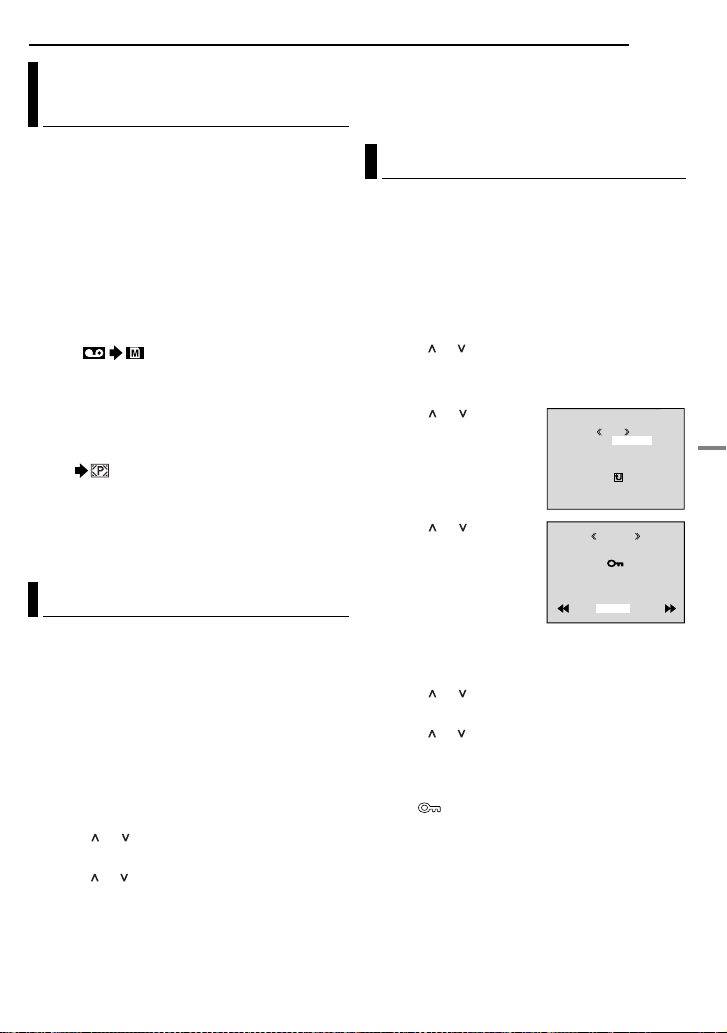
Dubbing Still Images Recorded On A Tape To A Memory Card
Still images can be dubbed from a tape to a
memory card.
1 Load a cassette. (墌 pg. 17)
2 Load a memory card. (墌 pg. 18)
3 Set “SNAP/SLOW” to the desired mode.
(except “SLOW”, 墌 pg. 37, 38)
4 Set the VIDEO/MEMORY Switch to “VIDEO”.
5 Set the Power Switch to “PLAY” while
pressing down the Lock Button located on the
switch.
6 Set “ COPY” to “ON”.
(墌 pg. 37, 42)
7 Press 4/9 to start playback.
8 At the point you want to dub, press 4/9
again to engage Still Playback.
9 To dub the image, press SNAPSHOT.
● The “ ” indication appears during dubbing.
NOTES:
● To use Playback Special effects with a video
image you wish to dub, perf orm up to step 9 using
the remote control. (墌 pg. 27)
● Images are dubbed in 640 x 480 pixels.
Resetting The File Name
By resetting the file name, a new folder will be
made. The new files you are going to make will
be stored in the new folder. It is convenient to
separate the new files from previously made
files.
1 To reset the file name...
...for images, display its playback screen.
(墌 pg. 30)
...for video clips, display its playback screen.
(墌 pg. 30)
2 Press MENU. The Menu Screen appears.
3 Press or to select “NO. RESET”, and
press SET. The NO. RESET screen appears.
4 Press or to select “EXECUTE”, and press
SET. The new folder (such as “101JVCGR”) will
be made and the file name of the next shot
starts from DVC00001.
ADDITIONAL FEATURES FOR D.S.C.
NOTE:
If the file name reaches DVC09999, a new folder
(such as “101JVCGR”) will be made and the file
name will start again from DVC00001.
EN 33
Protecting Files
The Protect mode helps prevent the accidental
erasure of files.
1 To protect the file...
...for images, display its playback screen.
(墌 pg. 30)
...for video clips, display its playback screen.
(墌 pg. 30)
2 Press MENU. The Menu Screen appears.
3 Press or to select “PROTECT”, and press
SET. The Sub Menu appears.
To protect the currently displayed file
4 Press or to select
“CURRENT”, and press
SET. The PROTECT
screen appears.
5 Press < or > to select
the desired file.
6 Press or to select
“EXECUTE”, and press
SET.
● To cancel protection,
select “RETURN”.
● Repeat steps 5 and 6 for
all files you want to
protect.
To protect all files stored in the memory card
4 Press or to select “PROT.ALL” , and press
SET. The PROTECT screen appears.
5 Press or to select “EXECUTE”, and press
SET.
● To cancel protection, select “RETURN”.
NOTES:
● If the “ ” mark appears, the currently displayed
file is protected.
● When the memory card is initialised or corrupted,
even protected files a re deleted. If y ou do not w ant
to lose important files, transfer them to a PC and
save them.
CUR
PROTECTM E NURENT
PROT.ALL
CANC.ALL
RETURN
ROTECTP
PROTECTED
RETURN
DIGITAL STILL CAMERA (D.S.C.) RECORDING & PLAYBACK
CONTINUED ON NEXT PAGE
Page 34

34 EN
ADDITIONAL FEATURES FOR D.S.C.
To Remove Protection
Before doing the following, perform steps 1 – 3
in “Protecting Files”.
To remove protection from the currently
displayed file
4 Press or to select “CURRENT”, and press
SET. The PROTECT screen appears.
5 Press < or > to select the desired file.
6 Press or to select “EXECUTE”, and press
SET.
● To cancel selection, select “RETURN”.
● Repeat steps 5 and 6 for all files you want to
remove protection.
To remove protection from all files stored in
the memory card
4 Press or to select “CANC.ALL”, and press
SET. The PROTECT screen appears.
5 Press or to select “EXECUTE”, and press
SET.
● To cancel selection, select “RETURN”.
Deleting Files
Previously stored files ca n be dele ted eith er one
at a time or all at once.
1 To delete the file...
...for images, display its playback screen.
(墌 pg. 30)
...for video clips, display its playback screen.
(墌 pg. 30)
2 Press MENU. The Menu Screen appears.
3 Press or to select “DELETE”, and press
SET. The Sub Menu appears.
To delete the currently displayed file
4 Press or to select
“CURRENT”, and press
SET. The DELETE screen
appears.
5 Press < or > to select
the desired file.
6 Press or to select
“EXECUTE”, and press
SET.
● To cancel deletion, select
“RETURN”.
● Repeat steps 5 and 6 for
all files you want to delete.
NOTE:
If the “ ” mark appears, the selected file is
protected and cannot be deleted.
To delete all files stored in the memory card
4 Press or to select “ALL”, and press SET.
The DELETE screen appear s.
5 Press or to select “EXECUTE”, and press
SET.
● To cancel deletion, select “RETURN”.
NOTES:
● Protected files (墌 pg. 33) cannot be deleted. To
delete them, remove protection first.
● Once files are deleted, they cannot be restored.
Check files before deleting.
CAUTION:
Do not remove the memory card or perform any
other operation (such as turning off the camcorder)
during deletion. Also, be sure to use the provided
AC Adapter, as the memory card may be corrupted
if the battery becomes exhausted during deletion. If
the memory card becomes corrupted, initialise it.
(墌 pg. 36)
DELE T E M E NURENT
CUR
ALL
RETURN
ELETED
DELE TE?
EXECUTE
RETURN
Page 35

Setting Print Information (DPOF Setting)
This camcorder is compatible with the DPOF
(Digital Print Order Forma t) standard in order to
support future systems such as automatic
printing. You can select one of the 2 print
information settings for images stored in the
memory card: “To Print All Still Image s (One
Print For Each)” or “To Print By Selecting Still
Images And Number Of Prints”.
NOTES:
● If you load a memory card already set as shown
below in a printer compatible with DPOF, it will
make prints of the selected still images
automatically.
● To print images recorded on a tape, first d ub them
to a memory card. (墌 pg. 33)
To Print All Still Images (One Print For Each)
1 Perform steps 1 – 3 in “Normal Playback Of
Images” (墌 pg. 30).
2 Press MENU. The Menu Screen appears.
3 Press or to select
“DPOF”, and press SET.
The Sub Menu appears.
4 Press or to select
“ALL 1”, and press SET.
The DPOF screen
appears.
5 Press or to select
“EXECUTE”, and press
SET. The normal playback
screen appears.
● To cancel selection, select
“RETURN”.
CUR
DPOF M E NURENT
ALL 1
RESET
RET URN
DPOF
ALL1 ?
EXECUTE
RETURN
ADDITIONAL FEATURES FOR D.S.C.
EN 35
To Print By Selecting Still Images And Number Of Prints
1 Perform steps 1 – 3 in “To Print All Still
Images (One Print For Each)”.
2 Press or to select
“CURRENT”, and press
DPOF
SET. The DPOF screen
appears.
3 Press < or > to select
the desired file.
SHEETS
00
RETURN
4 Press or to select the number indication
(00), and press SET.
5 Select the number of
prints by pressing to
DPOF
increase the number, or
to decrease the number,
and press SET.
● Repeat steps 3 through 5
for the desired number of
prints.
● The number of prints can be set up to 15.
● To correct the number of prints, select the image
again and change the number.
6 Press or to select
“RETURN”, and press
SHEETS
05
DPOF
SET. The “SAVE?”
appears.
● If you did not change any
settings in step 3 through
5, the Menu Screen
reappears.
SAVE?
EXECUTE
CANCEL
7 Press or to select “EXECUTE” to s av e the
setting you have just made, and press SET.
● To cancel selection, select “CANCEL”.
CONTINUED ON NEXT PAGE
DIGITAL STILL CAMERA (D.S.C.) RECORDING & PLAYBACK
Page 36

36 EN
ADDITIONAL FEATURES FOR D.S.C.
To Reset The Number Of Prints
1 Perform steps 1 – 3 in “To Print All Still
Images (One Print For Each)”.
2 Press or to select “RESET”, and press
SET. The DPOF screen appears.
3 Press or to select “EXECUTE”, and press
SET. The normal playback screen appears.
● To cancel selection, select “RETURN”.
● The number of prints is reset to 0 for all still
images.
CAUTION:
While performing the above, never disconnect
power, as this may cause the memory card to be
corrupted.
Initialising A Memory Card
You can initialise a memory card any time.
After initialising, all files and data stored in the
memory card, including those which have been
protected, are cleared.
1 Set the VIDEO/MEMORY Switch to
“MEMORY”.
2 Set the Power Switch to “PLAY” while
pressing down the Lock Button located on the
switch.
3 Press MENU. The Menu Screen appears.
4 Press or to select
“FORMAT”, and press
SET. The FORMAT
screen appears.
5 Press or to select
“EXECUTE”, and press
SET. The memory card is
initialised.
● When initialisation is finished, “NO IMAGES
STORED” or “NO E-MAIL CLIP STORED”
appears.
● To cancel initialisation, select “RETURN”.
CAUTION:
Do not perform any other operation (such as
turning off the camcorder) during initialisation.
Also, be sure to use the provided AC Adapter, as
the memory card may be corrupted if the battery
becomes exhausted during initialisation. If the
memory card becomes corrupted, initialise it.
ORMATF
ERASE ALL
EXECUTE
RETURN
DATA?EX I ST I NG
Page 37

Changing The Menu Settings
This camcorder is equipped with an easy-to-use,
on-screen menu system that simplifies many of
the more detailed camcorder settings.
(墌 pg.38–42)
VIDEO/
MEMORY
1 For Video an d D.S.C. Recording Menus:
● Set the VIDEO/MEMORY Switch to “VIDEO” or
“MEMORY”.
● Set the Power Switch to “M” while pressing down
the Lock Button located on the switch.
For Video Playback Menus:
● Set the VIDEO/MEMORY Switch to “VIDEO”.
● Set the Power Switch to “PLAY” while pressing
down the Lock Button located on the switch.
● For D.S.C. Playback Menus, refer to “D.S.C.
PLAYBACK” (墌 pg. 30).
2 Open the LCD monitor fully. (墌 pg. 19)
3 Press MENU. The Menu Screen appears.
4 Press or to select the desired function,
and press SET. The selected function menu
appears.
Screen for Video
and D.S.C.
Recording Menu
5 Setting procedure hereafter depends on the
selected function.
MENU
Power Switch
SET
Screen for Video
Playback Menu
DIPE WA
R/F
E
OF
F
W
– FA R ET
HIDE
B
– FA R
LADE
KC
– FA R
B
.WDE
C WI –
RNPE
RE
O
W I –
NDE
WO
I
PW
S WI
IDP
E
E–
L
ORPE D WI –
O
RO
S WI
PE
– LL
C
S WI –RETH
UTPE
Lock Button
ID O V E
DU
–STRE EO
DMSO N EO
OFONR–ATI NA R F
E C–MOD RE
OFCO Y P F–
L.V .DENA I
RCA KS BL N H
OFPUAINVTF–
S/
NRET UR
MENUS FOR DETAILED ADJUSTMENT
.Menus without Sub Menus
v WIPE/FADER
(墌 pg. 48)
r PROGRAM AE
(墌 pg. 48)
p EXPOSURE
(墌 pg. 45)
u W. BALANCE
(墌 pg. 47)
1) Press or to select
Selected
parameter
E RA ROG PM
OR S SP T
O W SN
TWILIGHT
SEPIA
MONOTONE
CLASSIC FILM
STROBE
the desired parameter.
● Example: r PROGRAM AE Menu
2) Press SET. Selection is complete. The Menu
Screen returns.
● Repeat the procedure if you wish to set other
function menus.
3) Press SET. The Menu Screen closes.
Menus with Sub Menus
m CAMERA (墌 pg. 38)
q MANUAL
(墌 pg. 39)
s SYSTEM (墌 pg. 39)
n
CAMERA DISPLAY
(墌pg. 40)
o DSC (墌 pg. 41)
t VIDEO (墌 pg. 41)
n VIDEO DISPLAY
(墌 pg. 42)
1) Press or to select
the desired function,
and press SET. The
Sub Menu appears.
● Example: m CAMERA
Menu
2) Press or to select
the desired parameter.
3) Press SET. Selection
is complete.
● Repeat the procedure if
you wish to set other
function menus.
4) Press SET. The
Menu Screen retur ns.
● Repeat the procedure if
you wish to set other function menus.
5) Press SET. The Menu Screen closes.
Selected function
C
E
MODRE
– ZO M
O
x
– UP GA N
I
C
NRETUR
Sub Menu
C
E
MODRE
C
E
MODRE
– ZO M
O
x
SNAP/SLOW
– UP GA N
I
C
X
–MIC AU
NRET UR
EN 37
A
OT I SP L GHT
ME A CA R
–
12ODU–D M SO N E TIB
60
FU– SNAP/SLOW LL
AG
MAIV –GAT NA I NOUN LA
B I X–MIC AU OHP NI
ME A CA R
–
ME A CA R
–
12ODU–D M SO N E TIB
60
FU– LL
AG
MAIV –GATNA I NOUN LA
B I
OHP NI
C
ADVANCED FEATURES
C
Page 38

38 EN
MENUS FOR DETAILED ADJUSTMENT
Recording Menus
CAMERA
The “m CAMERA” settings are effective when
the Power Switch is set to both “A” and “M”.
However, the menu settings can be cha ng ed
only when the Power Switch is set to “M”.
[ ] = Factory-preset
REC MODE
[SP]: To record in the SP (Standard Play) mode
LP: Long Play—more economical, providing 1.5
times the recording time.
NOTES:
● Audio Dubbing (墌 pg. 55) and Insert Editing
(墌 pg. 56) are possible on tapes recorded in the
SP mode.
● If the recording mode is switched, the play back
picture will be blurred at the switching point.
● It is recommended that tapes recorded in the LP
mode on this camcorder be played back on this
camcorder.
● During playback of a tape recorded on another
camcorder, blocks of noise may appear or there
may be momentary pauses in the sound.
SOUND MODE
[12BIT]: Enables video recording of stereo
sound on four separate channels, and is
recommended for use when performing Audio
Dubbing. (Equivalent to the 32 kHz mode of
previous models)
16BIT: Enables video reco rdin g of st ereo sound
on two separate channels. (Equivalent to the
48 kHz mode of previous models)
ZOOM
15X: When set to “15X” while using di gital zoom,
the zoom magnification will reset to 15X sinc e
digital zoom will be disengaged.
[60X]*: Allows you to use the Digital Zoom. By
digitally processing and mag nifying images,
zooming is possible from 15X (the optical zoom
limit), to a maximum of 60X digital mag nif ic ati on.
700X*: Allows you to use the Digital Zoom. By
digitally processing and mag nifying images,
zooming is possible from 15X (the optical zoom
limit), to a maximum of 700X digital
magnification.
* Available only when the VIDEO/MEMORY Switch
is set to “VIDEO”.
SNAP/SLOW
[FULL]: Snapshot mode with no frame
NEGA: Nega mode
PIN-UP: Pin-Up mode
FRAME: Snapshot mode with frame
SLOW: Live Slow mod e
[FULL] PIN-UP FRAMENEGA
For details on the procedure, refer to “Live Slow”
(墌 pg. 43) and “Snapshot (For Video
Recording)” (墌 pg. 44).
GAIN UP
OFF: Allows you to shoot dark scenes with no
picture brightness adjustment.
[AGC]: The ov erall appearance may be grainy,
but the image is bright.
AUTO : The shutter speed is aut omatically
adjusted. Shooting a subject in low or poor
lighting at slow shutter speed provid es a brighter
image than in the AGC mode, but the subject’s
movements are not smooth or natural. The
overall appearance may be grainy. While the
shutter speed is being automatically adjusted,
“ ” is displayed.
NAVIGATION
[MANUAL]: Enables thumbnail ima ges to be
made manually. (墌 pg. 50)
5SEC / 15SEC / 30SEC / 60SEC:
The captured image is stored in the memory
card as a thumbnail image when the recording
time is over the navigation time.
For example, “5SEC” is suitable to record short
scenes with the thumbnail images. (墌 pg. 49)
However, the stored thumbnail images may take
up a lot of memory. In this case, using the
memory card with large capacity is
recommended.
OFF: Disables the function.
● The “ ” indicator appears when “NAVIGA TION”
is set to other than “MANUAL” and “OFF”.
AUX MIC
NORMAL: Disables Biphonic Recording.
[BIPHONIC]: Enables Biphonic Recording.
(墌 pg. 51)
Page 39

MANUAL
The “q MANUAL” settings are effective only
when the Power Switch is set to “M”.
[ ] = Factory-preset
DIS
OFF: Disables the function.
[ON ]: To compensate for unstable images
caused by camera-shake, particularly at high
magnification.
NOTES:
● Accurate stabilisation may not be possible if hand
shake is excessive, or depending on the shooting
condition.
● The “ ” indicator blinks or goes out if the
Stabiliser cannot be used.
● Switch off this mode when recording with the
camcorder on a tripod.
5S
[OFF]: Disables 5-Second Recording.
5S: Enables 5-Second Recording. (墌 pg. 43)
Anim.: Allows you to record a few frames only.
By using an inanimate object and changing its
position between shots, you can record the
subject as though it is moving.
TELE MACRO
[OFF]: Disables the function.
ON: When the distance to the subject is less
than 1 m, set “TELE MACRO” to “ON”. You can
shoot a subject as large as possible at a
distance of approx. 50 (60*) cm.
* GR-DF473 only
NOTE:
Depending on the zoom position, the lens may go out
of focus.
WIDE MODE
[OFF]: Records with no change in the screen
ratio. For playback on a TV with a normal screen
ratio.
CINEMA** : Inserts black bands at the top
and bottom of the screen. The indicator
appears. During playback on wide-screen TVs,
the black bands at the top and bottom of the
screen are cut and the screen ratio becomes
16:9. When using this mode, refer to your widescreen TV’s instruction manual. During
playback/recording on 4:3 TVs/LCD monitor/
viewfinder, black bands are inserted at the top
and bottom of the screen and the image appears
like a letter boxed 16:9 movie.
MENUS FOR DETAILED ADJUSTMENT
EN 39
SQUEEZE** : For playback on TVs with an
aspect ratio of 16:9. Naturally expands the
image to fit the screen without distortion. The
indicator appears. When using this mode,
refer to your wide-screen TV’s instruction
manual. During playback/recording on 4:3 TVs/
LCD monitor/viewfinder, the image is elongated
vertically.
D.WIDE** : The indicator appears. The
zoom range is extended beyond the maximum
optical zoom wide angle range. This mode’s
wide angle setting is equivalent to using a 0.7X
wide conversion lens. Zooming is possible from
0.7X to 15X. This mode is suitable for shooting
in a small room. (GR-DF573 only)
** Available only when the VIDEO/MEMORY
Switch is set to “VIDEO”.
WIND CUT
[OFF]: Disengages the function.
ON : Helps cut down on noise created by
wind. The “ ” indicator appears. The quality of
the sound will change. This is normal.
SYSTEM
The “s SYSTEM” functions which are set when
the Power Switch is set to “M” are also applied
when the Pow er Switch is set to “PLAY”.
[ ] = Factory-preset
BEEP
OFF: Even though not heard while shooting,
shutter sound is recorded on the tape.
BEEP: The beep sounds when the power is
turned on or off, and at the beginning and end of
recording. It also activates the shutter sound
effect. (墌 pg. 28, 44)
[MELODY]: Instead of a bee p , a melo dy soun ds
when any operation is performed. It also
activates the shutter sound effect.
(墌 pg. 28, 44)
ADVANCED FEATURES
Page 40

40 EN
MENUS FOR DETAILED ADJUSTMENT
REMOTE
OFF: Disables the remote control operations.
[ON]: Enables the remote control operatio ns.
DEMO MODE
OFF: Automatic demonstration will not take
place.
[ON]: Demonstrates cert ain functions such as
Program AE with special effects, etc., and can
be used to confirm how these functions operate.
Demonstration starts in the following cases:
● When the Menu Screen is closed after “DEMO
MODE” is turned “ON”.
● With “DEMO MODE” set to “ON”, if there is no
operation for about 3minutes after the Power
Switch is set to “A” or “M”.
● Performing any operation during the
demonstration stops the demonstratio n
temporarily. If no operation is performed for more
than 3 minutes after that, the demonstration will
resume.
NOTES:
● If a cassette is in the camcorder, the
demonstration cannot be turned on.
● “DEMO MODE” remains “ON” even if the
camcorder power is turned off.
● If “DEMO MODE” remains “ON”, some functions
will not be available. After viewing demo, set to
“OFF”.
PRIORITY
[LCD]: The image is displayed on the LCD
monitor when the viewfinder is pulled out while
the LCD monitor is opened.
FINDER: The image is displayed in the
viewfinder when the viewfinder is pulled out
while the LCD monitor is opened.
CAM RESET
EXECUTE: Resets all settings to the factory-
preset.
[RETURN]: Does not reset all settings to the
factory-preset.
CAMERA DISPLAY
● The “n” (CAMERA DISPLAY) settings are
effective even when the Power Switch is set to
“A”. However, the menu settings can be changed
only when the Power Switch is set to “M”.
● The “n” (CAMERA DISPLAY) settings except
“BRIGHT”, “LANGUAGE” and “AUDIO LEV.” are
effective only for shooting.
[ ] = Factory-preset
BRIGHT
墌 pg. 17, “Brightness Adjustment Of The
Display”
ON SCREEN
LCD: Keeps the camcorder’s display (except the
date, time and time code) from appearing on the
connected TV screen.
[LCD/TV]: Makes the camcorder’s display
appear on screen when the camcorder is
connected to a TV.
DATE/TIME
OFF: The date/time does not appear.
[AUTO]: Displays the date/time for approx. 5
seconds when the Power Switch is set from
“OFF” to “A” or “M”.
ON: The date/time is always displayed.
● The date indication can also be turned on/off by
pressing the DISPLAY Button on the remote
control. (墌 pg. 23, 52)
TIME CODE
[OFF]: Time code is not displayed.
ON: Time code is displayed on the camcorder
and on the connected TV. Frame numbers are
not displayed during recording. (墌 pg. 21)
LANGUAGE
[ENGLISH] / FRANÇAIS / DEUTSCH /
ESPAÑOL / ITALIANO / NEDERLANDS /
PORTUGUÊS / РУССКИЙ ///
B.MELAYU //
AUDIO LEV.
[OFF]: Auxiliary microphone le v el indic ator does
not appear.
ON: Displays auxiliary microphone level
indicator when optional microphone is
connected. (墌 pg. 8)
CLOCK ADJ.
墌 pg. 16, “Dat e/Time Settings”
Page 41

DSC
[ ] = Factory-preset
QUALITY
[FINE] / STANDARD
The Picture Quality mode can be selec ted to
best match your needs. Two Picture Quality
modes are available: FINE ( ) and
STANDARD ( ) (in order of quality).
NOTE:
The number of storable images depends on the
selected picture quality as well as the composition
of the subjects in the images and the type of
memory card being used. (墌 pg. 28)
IMAGE SIZE
640 x 480 / 1024 x 768 / [1152 x 864]*/
1600 x 1200*
The Image Size mode can be selected to best
match your needs. (墌 pg. 28)
* GR-DF573 only
NOTE:
The setting can be changed only when the VIDEO/
MEMORY Switch is set to “MEMORY”.
REC SELECT
[ (TAPE)]: When Snapshot recording is
performed with the VIDEO/MEMORY Switch set
to “VIDEO”, still images are recorded only onto
the tape.
/ (TAPE/CARD): When Snapshot
recording is performed with the VIDEO/
MEMORY Switch set to “VIDEO”, still images
are recorded not only onto the tape but also in
the memory card (640 x 480 pixels). In this
mode, the “SNAP/SLOW” s elec tio n in CAMERA
Menu is also applicable to memory card
recording.
INT.SHOT
[OFF]: Disables the function.
ON: Enables interval shooting. (墌 pg. 29)
MENUS FOR DETAILED ADJUSTMENT
INT.TIME
15SEC/30SEC/[1MIN]/2MIN/5MIN/10MIN
30MIN/60MIN
Allows you to select the shooting interval for
interval shooting. (墌 pg. 29)
EN 41
/
Playback Menus
VIDEO
[ ] = Factory-preset
SOUND MODE and NARRATION
During tape playbac k, the camcord er detects the
sound mode in which the recording was made,
and plays the sound back. Select the type of
sound to accompany your playback picture.
According to the menu access explanation on
page 37, select “SOUND MODE” or
“NARRATION” from the Menu Screen and set it
to the desired parameter.
SOUND MODE
[STEREO ]: Sound is output on both “L” and
“R” channels in stereo.
SOUND L : Sound from the “L” channel is
output.
SOUND R : Sound from the “R” channel is
output.
NARRATION
[OFF]: Original sound is output on both “L” and
“R” channels in stereo.
ON: Dubbed sound is output on both “L” and “R”
channels in stereo. (墌 pg. 55)
MIX: Original and dubbed sounds ar e comb ined
and output in stereo on both “L” and “R”
channels.
ADVANCED FEATURES
Page 42

42 EN
Allows you to set the video recording mode (SP
or LP) depending on your preference. It is
recommended you use “REC MODE” in VIDEO
Menu when using this camcorder as a recorder
during dubbing. (墌 pg. 52, 53)
[OFF]: When the SNAPSHOT b utt on is pres sed
during tape playback, the playback image
pauses and normal playback will resume after
approximately 6 seconds. (The still image is not
recorded.)
ON: Enables dubbing of images recorded on a
tape to a memory card. (墌 pg. 33)
IMAGE SEL. / TAPE SEL. / ALL / RETURN
墌 pg. 50, “To delete thumbnail images”
墌 pg. 22, “Blank Search”
[OFF]: Disables audio/video signal input from
the AV and S-Video connectors. (墌 pg. 52)
ON: Enables audio/video signal input from th e
AV and S-Video connectors. (墌 pg. 52)
MENUS FOR DETAILED ADJUSTMENT
REC MODE [SP] / LP
COPY
NAVI.DEL.
BLANK SRCH
S/AV INPUT
NOTE:
When set to “ON”, the S-video input has a priority to
the composite video input.
SYSTEM
Each setting is linked with “s SYSTEM”, which
appears when the Power Switch is set to “M”.
(墌 pg. 37)
● The parameters are the same as in the
description on page 39.
VIDEO DISPLAY
The “n” (VIDEO DISPLAY) settings are
effective only for video playback except
“BRIGHT”, “LANGUAGE” and “AUDIO LEV.”.
● The parameters (except “OFF” in ON SCREEN
settings) are the same as in the description
(CAMERA DISPLAY) on page 40.
[ ] = Factory-preset
BRIGHT
墌 pg. 17, “Brightness Adjustment Of The
Display”
ON SCREEN OFF / [LCD] / LCD/TV
When set to “OFF”, the camcorder ’s display
disappears.
DATE/TIME [OFF] / AUTO / ON
When set to “A UT O”, the date/time are displa yed
in the following cases:
● When playback starts. The camcorder displays
the date/time when scenes are recorded.
● When the date is changed during playback.
TIME CODE [OFF] / ON
墌 pg. 21, “Time Code”
LANGUAGE
[ENGLISH] / FRANÇAIS / DEUTSCH /
ESPAÑOL / ITALIANO / NEDERLANDS /
PORTUGUÊS / РУССКИЙ ///
B.MELAYU //
AUDIO LEV. [OFF] / ON
墌 pg. 40, “AUDIO LEV.”
Page 43

FEATURES FOR RECORDING
EN 43
LED Light
LED Light can be used to
brighten the subject in the dark
place during video recording or
D.S.C. shooting.
1 Press LIGHT repeatedly to
change the setting.
OFF: Turns off the light.
ON: The light is on always. (
appears.)
AUTO: The light turns on automatically when
dark. ( appears.)
LED Light
2 Press the Recording Start/Stop Button to
start video recording or SNAPSHOT to shoot a
still image.
NOTES:
● Be careful not to point the LED Light directly to
eyes.
● If the light does not reach the subject when the
LED light setting is
function will be activated, and makes it possible to
shoot the subject brighter.
● There is a difference in the brightness of the
images shot between the centre area which is
illuminated by the LED Light and the surrounding
areas (which will be darker).
● Since subjects are shot at a reduced shutter
speed when the LED Light setting is “ON”, they
will appear slightly blurred.
“ON”, the Night Scope
Live Slow
This feature is useful for recording or playing
back precious or hard-to-see moments at a slow
speed. Sound is recorded and played back in
real time.
1 Set the VIDEO/MEMORY Switch to “VIDEO”.
2 Set “SNAP/SLOW” to “SLOW”.
(墌 pg. 37, 38) The Live Slow indicator “ ”
appears.
3 Press SLOW during recording or playback.
● The moving pictures are divided into four
frames. They are recorded or played back for
1.5 seconds, and then normal recording or
playback resumes.
5-Second Recording
Record a vacation or an important event in 5second clips to keep the action moving. This
function is available only for video recording.
1 Set “5S” to “5S”. (墌 pg. 39)
● The “5S” indicator appears.
2 Press the Recording Start/Stop Button to
start recording, and after 5 seconds the
camcorder enters Record-Standby mode
automatically.
● Even if you press the Recordin g Start/Stop Button
again within 5 seconds after recording starts,
Record-Standby mode is not engaged.
3 To exit the 5S mode, select “OFF” in step 1.
To take a snapshot in the 5-second recording
mode
Instead of pressing the Recording Start/Stop
Button in step 2, select the desired Snapshot
mode in CAMERA Menu (墌 pg. 38), then press
SNAPSHOT. The camcorder records a 5second still. When “5S” is set to “Anim.”, this
function is not available.
NOTE:
When “5S” is set to “Anim.”, the 5-Second
Recording mode is not available. Animation
recording of a few frames only is taken instead.
ADVANCED FEATURES
Page 44

44 EN
FEATURES FOR RECORDING
Night Scope Snapshot (For Video Recording)
Makes dark subjects or areas even brighter than
they would be under good natural lighting.
Although the recorded image is not grainy, it ma y
look as if it is strobing due to the slow shutter
speed.
1 Set the Power Switch to “M”.
2 Set “r” to “NIGHT SCOPE”. (墌 pg. 48) The
Night Scope indicator “ ” appears.
● The shutter speed is automatically adjusted to
provide up to 25 times sensitivity.
● “ ” appears beside “ ” while the shutter speed
is being automatically adjusted.
To deactivate Night Scope
Set “r” to “OFF” so that the Night Scope
indicator disappears.
NOTES:
● During Night Scope, the following functio ns or
settings cannot be activated and its indicator
blinks or goes out:
• Some modes of “Prog ram AE With Special
Effects” (墌 pg. 48).
• “GAIN UP” in CAMERA Menu (墌 pg. 38).
• “DIS” in MANUAL Menu (墌 pg. 39).
● During Night Scope, it may be difficult to bring the
camcorder into focus. To prevent this, use of a
tripod is recommended.
This feature lets yo u record still imag es that look
like photographs onto a tape.
1 Set the VIDEO/MEMORY Switch to “VIDEO”.
2 Set the Power Switch to “M”.
3 Set “SNAP/SLOW” to the desired mode.
(墌 pg. 37, 38) The Snapshot indicator “ ”
appears.
4 Press SNAPSHOT.
● There is the sound effect of a shutter closing.
● The “O” indication appears and a still image
will be recorded for approx. 6 seco nds, then the
camcorder re-enters the Record-Standby mode.
● You can perform Snapshot also during recording.
A still image will be recorded for approx.
6 seconds, then the normal recording resumes.
● Regardless of the Pow er Swit ch position (“A” or
“M”), Snapshot recording takes place using the
selected Snapshot mode.
Motor Drive Mode
Keeping SNAPSHOT pressed in step 4 provides
an effect similar to serial photography. (Interval
between still images: approx. 1 second)
● The Motor Drive mode is disabled when “REC
SELECT” is set to “ / ”. (墌 pg. 41)
Page 45

FEATURES FOR RECORDING
EN 45
Manual Focus
The camcorder’s Full Range AF system offers
continuous shooting ability from close-up (as
close as approx. 5 cm to the subject) to infinity.
However, correct focus may not be obtained
depending on the shooting condition. In this
case, use the manual focus mode.
1 Set the Power Switch to
“M”.
2 Press FOCUS. The
manual focus indicator
appears.
3 Press < or > to focus on
a subject.
● When the focus level
cannot be adjusted any
further or closer, “ ” or “ ” will blink.
4 Press SET. Focus adjustment is complete.
To re se t to Auto Focus
Press FOCUS twice or set the Power Switch to
“A”.
Manual focus is recommended in situations
listed below.
● When two subjects overlap in the same scene.
● When illumination is low.*
● When the subject has no contrast (difference in
brightness and darkness), such as a flat, onecolour wall, or a clear, blue sky.*
● When a dark object is barely visible in the LCD
monitor or the viewfinder.*
● When the scene contains minute patterns or
identical patterns that are regularly repeated.
● When the scene is affected by sunbeams or light
reflecting off the surface of a body of water.
● When shooting a scene with a high-contrast
background.
* The following low-contrast warnings appear
blinking: , , and .
Manual focus
indicator
Exposure Control
Manual exposure control is recommended in the
following situations:
● When shooting using reverse lighting or when the
background is too bright.
● When shooting on a reflective natural ba c kg round
such as at the beach or when skiing.
● When the background is ov erly dark or the subject
is bright.
1 Set the Power Switch to “M”.
2 Set “p” to “MANUAL”. (墌 pg. 37)
● The exposure control indicator appears.
3 To brighten the image, press >. T o darken th e
image, press <. (maximum ±6)
● +3 exposure has the same effect as the backlight
compensation. (墌 pg. 46)
● –3 exposure has the same effect as when “r” is
set to “SPOTLIGHT”. (墌 pg. 49)
4 Press SET. Exposure adjustment is
complete.
To return to automatic exposure control
Select “AUTO” in step 2. Or, set the Power
Switch to “A”.
NOTES:
● You cannot use the manual exposure control at
the same time when “r” is set to “SPOTLIGHT”
or “SNOW” (墌 pg. 48), or with the backlight
compensation.
● If the adjustment does not cause any visible
change in brightness, set “GAIN UP” to “AUTO”.
(墌 pg. 37, 38)
ADVANCED FEATURES
Page 46

46 EN
FEATURES FOR RECORDING
Iris Lock
Like the pupil of the human eye, th e iris
contracts in well-lit environments to keep too
much light from entering, and dilates in dim
environments to allow in more light.
Use this function in the follo w in g situations:
● When shooting a moving subject.
● When the distance to the subject changes (so its
size in the LCD monitor or the viewfinder
changes), such as when the subject is backing
away.
● When shooting on a reflective natural bac kg round
such as at the beach or when skiing.
● When shooting objects under a spotlight.
● When zooming.
1 Set the Power Switch to “M”.
2 Set “p” to “MANUAL”. (墌 pg. 37)
● The exposure control indicator appears.
3 Adjust zoom so that the subject fills the LCD
monitor or the viewfinder, then press and hold
SET for over 2 seconds. The exposure control
indicator and the “ ” indication appear.
4 Press SET. The “ ” indication changes to
“ ” and the iris is locked.
To return to automatic iris control
Select “AUT O” in step 2. O r, set the Power
Switch to “A”.
● The exposure control indicator and “ ”
disappear.
To lock the exposure control and the iris
After step 2, adjust the exposure by pressing
or . Then lock the iris in steps 3 and 4. For
automatic locking, select “AUTO” in step 2. The
exposure control and the iris become automatic.
Backlight Compensation
Backlight compensation brightens the subject
quickly.
With simple operation, backlight compensation
feature brightens the dark subject portion by
increasing the exposure.
1 Set the Power Switch to “M”.
2 Press BACK LIGHT so that the Backlight
Compensation indicator “ ” appears.
To cancel Backlight Compensation
Press BACK LIGHT twice so that the “ ”
indicator disappears.
NOTE:
Using Backlight Compensation may cause the light
around the subject to become too bright and the
subject to become white.
Spot Exposure Control
Selection of a spot metering area enables more
precise exposure compensation. You can select
one of the three metering are as on the LCD
monitor/viewfinder.
1 Set the Power Switch to “M”.
2 Press BACK LIGHT twice so that the Spot
Exposure Control indicator “ ” appears.
● A spot metering area frame appears at the
centre of the LCD monitor/viewfinder.
3 Press > or < to select the desired spot
metering area frame.
4 Press SET.
● Spot Exposure Control is engaged.
● Exposure is adjusted to mak e the brightness o f
the selected area most appropriate.
To lock the iris
After step 3, press and hold SET over 2
seconds. The “ ” indication appears and the
iris is locked.
To cancel Spot Exposure Control
Press BACK LIGHT once so that the “ ”
indicator disappears.
NOTES:
● You cannot use the Spot Exposure Control at the
same time with following functions.
• “SQUEEZE” in “WIDE MODE” (墌 pg. 39)
• “STROBE” in “PROGRAM AE” (墌 pg. 48)
• Digital Zoom (墌 pg. 20)
• Manual Exposure Control
● Depending on the shooting location and condition,
optimum result may not be attained.
Page 47

FEATURES FOR RECORDING
White Balance Adjustment Manual White Balance Adjustment
The white balance refers to the correctness of
colour reproduction under variou s lighting. If the
white balance is correct, all other colo ur s will b e
accurately reproduced.
The white balance is usually adjusted
automatically. However, more advanced
camcorder operators contro l this fun cti on
manually to achieve a more professional colour/
tint reproduction.
To change the setting
Set “u” to the desired mode. (墌 pg. 37)
● The selected mode indicator except “AUTO”
appears.
[AUTO]: White balance is adjusted
automatically.
MWB: Adjust the white balance manually
when shooting under various types of l ighting.
(墌 “Manual White Balance Adjustment”)
FINE: Outdoors on a sunny day.
CLOUD: Outdoors on a cloudy day.
HALOGEN: A video light or similar type of
lighting is used.
[ ] = Factory-preset
To return to automatic white balance
Set “u” to “AUTO”. (墌 pg. 37)
Or, set the Power Switch to “A”.
Adjust the white
balance manually when
shooting under various
types of lighting.
1 Set the Power
Switch to “M”.
White paper
2 Hold a sheet of plain
white paper in front of the subject. Adjust zoom
or position yourself so that the white paper fills
the screen.
3 Select “MWB” in “u W.BALANCE” menu.
(墌 pg. 37) then press and hold MENU until
begins blinking rapidly.
● When the setting is completed, stops blinking.
4 Press MENU twice. The Menu Screen closes
and the Manual White Balance indicator is
displayed.
NOTES:
● In step 2, it may be difficult to focus on the white
paper. In such a case, adjust focus manually.
(墌 pg. 45)
● A subject can be shot under various types of
lighting conditions indoors (natural, fluorescent,
candlelight, etc.). Because the colour temperature
is different depending on the light source, the
subject tint will differ depending on the white
balance settings. Use this function for a more
natural result.
● Once you adjust white balance manually, the
setting is retained even if the pow er is turned off or
the battery removed.
EN 47
ADVANCED FEATURES
Page 48

48 EN
FEATURES FOR RECORDING
Wipe Or Fader Effects
These effects let you make pro-style scene
transitions. Use them to spice up the transition
from one scene to the next.
Wipe or Fader works when video recording is
started or stopped.
1 Set the VIDEO/MEMORY Switch to “VIDEO”.
2 Set the Power Switch to “M”.
3 Set “v” to the desired mode. (墌 pg. 37)
● The WIPE/F ADER menu disappears and the
effect is reserved.
● The selected effect indicator appears.
4 Press the Recording Star t/Stop Button to
activate the Fade-in/out or Wipe-in/out.
To deactivate the selected effect
Select “OFF” in step 3. The effect indicator
disappears.
NOTES:
● You can extend the length of a Wipe or Fader by
pressing and holding the Recording Start/Stop
Button.
● Some Wipe/Fader Effects cannot be used with
certain modes of Program AE with special effects.
(See the right column.) In this case, the selected
indicator blinks or goes out.
WIPE/FADER
OFF: Disables the function. (Factory-preset)
FADER–WHITE: Fade in or out with a white
screen.
FADER–BLACK: Fade in or out with a blac k
screen.
FADER–B.W: Fade in to a colour screen
from a black and white scre en , or fade out from
colour to black and white.
WIPE–CORNER: Wipe in on a b lac k screen
from the upper right to the lower left corner, or
wipe out from lower left to upper right, leaving a
black screen.
WIPE–WINDOW: The scene starts in the
centre of a blac k scr een an d wi pes in t ow ar d the
corners, or comes in from the co rners, g ra dua lly
wiping out to the centre.
WIPE–SLIDE: Wipe in from right to left, or
wipe out from left to right.
WIPE–DOOR: Wipe in as the two halves of
a black screen open to the left and right,
revealing the scene, or wipe out and the black
screen reappears from left and right to cover the
scene.
WIPE–SCROLL: The scene wipes in from
the bottom to the top of a b lack screen, or wipes
out from top to bottom, leaving a black screen.
WIPE–SHUTTER: Wipe in from the centre
of a black screen toward the top and bottom, or
wipe out from the top and bottom toward the
centre leaving a bla ck screen.
Program AE With Special Effects
1 Set the Power Switch to “M”.
2 Set “r” to the desired mode. (墌 pg. 37)
● The PROGRAM AE menu disappears and the
selected effect is activated.
● The selected effect indicator appears.
To deactivate the selected effect
Select “OFF” in step 2. The effect indicator
disappears.
NOTES:
● Program AE with special effects cannot be
changed during recording.
● Some modes of Program AE with specia l effects
cannot be used during Night Scope.
● When a subject is too bright or reflectiv e, a v ertical
streak may appear (smear phenomenon). Smear
phenomenon tends to occur when “SPORTS” or
any mode of “SHUTTER 1/250 – 1/4000” is
selected.
● Some modes of Program AE with specia l effects
cannot be used with certain Wipe/Fader effects.
(See the left column.) In this case, the selected
indicator blinks or goes out.
Page 49

PROGRAM AE
OFF: Disables the function. (Factory-pre set)
NIGHT SCOPE: (墌 pg. 44)
SHUTTER 1/50: The shutter speed is fixed
at 1/50th of a second. Black bands that usually
appear when shooting a TV screen become
narrower.
SHUTTER 1/120: The shutter speed is
fixed at 1/120th of a second. The flickering that
occurs when shooting under a fluores ce nt light
or mercury-vapour lamp is reduced.
SHUTTER 1/250/ SHUTTER 1/500/
SHUTTER 1/1000*/ SHUTTER 1/2000*/
SHUTTER 1/4000*: These settings allow fast-
moving images to be captured one frame at a
time, for vivid, stable slow-motion playback by
fixing shutter speed variables. Use these
settings when an automatic adjust ment does not
work well, using SPORTS mode. The faster the
shutter speed, the darker the picture becomes.
Use the shutter function under good lighting
conditions.
SPORTS
(Variable Shutter Speed: 1/250 – 1/4000):
This setting allows fast-moving images to be
captured one frame at a time, for vivid, stable
slow-motion playback. The faster the shutter
speed, the darker the picture becomes. Use the
shutter function under good lighting cond itions.
SNOW: Compensates for subjects that may
otherwise appear too dark when shooting in
extremely bright surroundings such as in the
snow.
SPOTLIGHT: Compensates for subjects
that may otherwise appear too bright when
shooting under extremely strong direct lighting
such as spotlights.
TWILIGHT: Makes evening scenes look
more natural. White Balance (墌 pg. 47) is
automatically set to “ ”, but can be changed to
your desired setting. When Twilight is chosen,
the camcorder automatically adjusts the focus
from approx. 10m to infinity. From less than 10
m, adjust the focus manually.
FEATURES FOR RECORDING
SEPIA: Recorded scenes have a brownish
tint like old photos. Combine this with the
Cinema mode for a classic look.
MONOTONE: Like classic black and white
films, your footage is shot in B/W. Used together
with the Cinema mode, it enhances the “classic
film” effect.
CLASSIC FILM*: Gives recorded scenes a
strobe effect.
STROBE*: Your recording looks like a
series of consecutive snapshots.
MIRROR*: Creates a mirror image on the
right half of the screen, juxtaposed to the normal
image on the other half.
* Available only when the VIDEO/MEMORY Switch
is set to “VIDEO”.
EN 49
Navigation Function
The Navigation Function helps you check tape
contents by making thumbnail images on a
memory card.
Before continuing
T o use Navigation functions, load a cassette and
memory card, then set the VIDEO/MEMORY
Switch to “VIDEO”.
To make thumbnail images during video recording automatically
1 Set “NAVIGATION” to the desired navigation
storing time. (墌 pg. 37, 38)
● If the “ ” indicator appears blinking on the
screen, wait until it stops blinking. If it does not
stop blinking after a while, check if a memory card
is loaded.
2 Set the Power Switch to “A” or “M”.
3 Press the Recording Start/Stop Button to
start recording.
● When the recording time is over the navigation
time set in step 1, “ ” appears briefly, then the
image of the point where recording is started is
captured and stored in the memory card as a
thumbnail image.
● If the Recording Start/Stop button is pressed
before “ ” stops blinking, the image of the point
where the loaded memory card is recognised is
captured.
4 Press the Recording Start/Stop Button to
stop recording.
ADVANCED FEATURES
CONTINUED ON NEXT PAGE
Page 50

50 EN
FEATURES FOR RECORDING
To make thumbnail images after video
recording manually
1 Set “NAVIGATION” to “MANUAL”.
(墌 pg. 37, 38)
2 Set the Power Switch to “A” or “M”.
3 After the recording, press STORE.
● The “ ” indicator appears briefly and the
captured image is stored in the memory card as a
thumbnail image.
NOTES:
● The remaining number of storable thumbnail
images also appears on the screen when it
reaches 10 or less. If “REC SELEC T ” is se t to
“ / ” in DSC Menu, the number shows
how many 640 x 480 pixel images can be stored.
● If “5S” is set to “5S” or “Anim.” in MANUAL Menu,
the NAVIGATION function will not work properly.
To find scenes on tape using thumbnail images (Navigation Search)
1 Set the Power Switch to “PLAY”.
2 Press INDEX during video playback or stop
mode.
● The loaded cassette’s
Navigation thumbnail
image screen appears.
3 Press >/</ / to select
the desired image, and
TC : 13 : 2 3 : 1 5
1 2 3
4 5
press SET.
● The “NAVIGATION
SEARCH” indication appears blinking and the
camcorder starts searching the tape for the
relevant point of the selected thumbnail image.
To cancel Navigation search midwa y
Press 4/9, 3, 5 or 8.
ONITNAV IGA
.54DATE : 2 ’04 3:29
To add thumbnail images during video playback
1 Set the Power Switch to “PLAY”.
2 Press 4/9 to start video playback.
3 Press STORE at the desired point.
● The “ ” indicator appears briefly and the image
of the point where STORE is pressed is stored in
the memory card as a thumbnail image.
To delete thumbnail images
1 Set the Power Switch to “PLAY”.
2 Press MENU. The Menu Screen appears.
3 Press SET to select “t”. The VIDEO Menu
appears.
4 Press or to select
“NAVI.DEL.”, and press
DMSO N EO
SET. The Sub Menu
appears.
5 By pressing or :
Select “IMAGE SEL.” to
S
NRETUR
delete the currently
displayed thumbnail image.
Select “TAPE SEL.” to delete all thumbnail
images for the tape which contains the currently
displayed image.
Select “ALL” to delete all thumbnail images
stored in the memory card at once.
6 Press SET. The
NAVIGATION screen
appears.
7 Press or to select
“EXECUTE”, and press
SET.
● Press < to display the
previous image. Press > to displa y the next image.
● To cancel deletion, select “RETURN”.
● Thumbnail images cannot be deleted during vi deo
playback.
ETEDEL CURRENT ?
EXECUTE
RETURN
ID O V E
DU
–STRE EO
OFONR–AT I NA R F
E C–MODRE
IG NANAV T I O
OFCO Y P F–
L.V .DENA I
IMAGE SEL.
RCA KS BL N H
TAPE SEL.
ALL
PUAINVT
/
RETURN
511 .62:20.004
Page 51

CAUTION:
Do not remove the memory card or perform any
other operation (such as turning off the camcorder)
during deletion. Also, be sure to use the provided
AC Adapter, as the memory card may be corrupted
if the battery becomes exhausted during deletion. If
the memory card becomes corrupted, initialise it.
NOTES:
● Be sure to always use the same tape and memory
card together as they were during recording;
otherwise, the camcorder cannot recognise Tape
and Memory Card IDs to perform Navigation
Function properly.
● Check if an appropriate tape and memory card
are loaded when the following messages appear:
“UNABLE TO USE NAVIGATION”, “THIS
MEMORY CARD IS NOT COMPATIBLE”.
● If you change the memory card while shooting on
one tape, two memory cards will share the tape’s
thumbnail images. We recommend that you use
one memory card for one tape.
● Navigation Search does not work if the current
position is at a blank portion on the tape. Also, do
not leave a b lank portion partway through the tape
when shooting; otherwise, Navigation Function
does not work properly.
● Before shooting newly over a recorded tape, be
sure to delete all thumbnail images of the pre vious
recording from the relevant memory card.
● If you copy thumbnail images from one memory
card to another via a PC, Navi gat ion Sea rch does
not work with the copied memory card.
FEATURES FOR RECORDING
EN 51
Biphonic Recording
For Biphonic Playback (墌 pg. 24), perform the
following procedure.
Mic for Biphonic
(provided)
Core filter (provided)
Audio extension cable
1 Connect the Mic for Biphonic to the MIC
connector and put them on to your ears.
2 Perform steps 1 – 4 in “Basic Recording”
(墌 pg. 19).
3 Set “AUX MIC” to “BIPHONIC”.
(墌 pg. 38, 40)
● “ ” appears on the display.
4 To start recording, press the Recording Start/
Stop Button.
NOTES:
● When you put on Mic for Biphonic, never confuse
left and right channel of it.
● During Biphonic
recording, be sure to
turn your face toward
the shooting subject
along with the
camcorder. Otherwise
the sound does not
correspond with the
footage.
● Some noises may be
picked up when you
touch the Mic for Biphonic during recording.
● Be sure to set “AUX MIC” t o “NOR MAL” when you
use a microphone other than the Mic for Biphonic.
(provided)
To MIC connector
Open the cover.
ADVANCED FEATURES
Page 52

52 EN
EDITING
Dubbing To Or From A VCR
Open the cover.
To S connector
To AV connector
VCR
AV cable
(provided)
S cable
(optional)
2413
TV
A To S-VIDEO IN or OUT*
B Yellow to VIDEO IN or OUT
C Red to AUDIO R IN or OUT
D White to AUDIO L IN or OUT
* Connect when your TV/VCR has an S-VIDEO IN/
OUT connector. In this case, it is not necessary to
connect the yellow video cable.
NOTE:
The S-Video cable is optional. Be sure to use the
YTU94146A S-Video cable. Consult the JVC
Service Center described on the sheet included
in the package for details on its availability.
Make sure to connect the end with a core filter
to the camcorder. The core filter reduces
interference.
To use this camcorder as a player
1 Following the illustrations, connec t the
camcorder and the VCR’s input connectors.
2 Start playback on the camcorder. (墌 pg. 22)
3 At the point you want to start dubbing, start
recording on the VCR. (Refer to the VCR’s
instruction manual.)
4 To stop dubbing , sto p re co rd ing on the VCR,
then stop playback on the camcorder.
NOTES:
● It is recommended to use the AC Adapter as
the power supply instead of the battery pack.
(墌 pg. 15)
● To choose whether or not the following displays
appear on the connected TV
• Date/time
Set “DATE/TIME” to “AUTO”, “ON” or “OFF”.
(墌 pg. 37, 42) Or, press DISPLAY on the
remote control to turn on/off the date indication.
• Time code
Set “TIME CODE” to “OFF” or “ON”.
(墌 pg. 37, 42)
• Indications other than date/time and time code
Set “ON SCREEN” to “OFF”, “LCD” or “LCD/
TV”. (墌 pg. 37, 42)
To use this camcorder as a recorder
1 Following the illustrations, connec t the
camcorder and the VCR’s output connectors.
2 Set “REC MODE” to “SP” or “LP”. (墌 pg. 38)
3 Set the camcorder’s Power Switch to “PLAY”.
4 Set “S/AV INPUT” to “ON”. (墌 pg. 37, 42)
5 Press the Recording Start/Stop Button to
engage the Record-Pause mode.
● The “ ” indication appears on the screen.
A/V IN
6 Start playback on the player.
7 At the point you want to start dubbing, press
the Recording Start/Stop Button to start
dubbing. The indication rotates.
8 Press the Recording Start/Stop Button again
to stop dubbing. The indication stops
rotating.
9 Press 8 to return to the normal playback
mode.
NOTES:
● After dubbing, set “S/AV INPUT” back to “OFF”.
● Analogue signals can be converted to digital
signals with this procedure.
● It is also possible to dub from another camcorder.
Page 53

Dubbing To Or From A Video Unit Equipped With A DV Connector (Digital Dubbing)
It is also possible to copy recorded scenes from
the camcorder onto another vide o unit eq uipped
with a DV connector. Since a digital signal is
sent, there is little if any image or sound
deterioration.
To DV IN/OUT
Core filter
Video unit equipped with DV connector
DV cable (optional)
To DV IN/OUT
EDITING
To use this camcorder as a player
EN 53
1 Make sure all u nits are turned off.
2 Connect this camcorder to a video unit
equipped with a DV input connector using a DV
cable as shown in the illustration.
3 Star t playback on the camcorder. (墌 pg. 22)
4 At the point you want to start dubbing, start
recording on the video unit. (Refer to the video
unit’s instruction manual.)
5 To stop dubbing, stop recording on the video
unit, then stop playback on this camcorder.
NOTES:
● It is recommended to use the AC Adapter as
the power supply instead of the battery pack.
(墌 pg. 15)
● If a blank portion or disturbed image is played
back on the player during dubbing, the d ubb in g
may stop so that an unusual image is not dubbed.
● Even though the DV cable is connected correctly,
sometimes the image may not appear in step 4. If
this occurs, turn off the power and make
connections again.
● If “Playback Zoom” (墌 pg.27) or “Playback
Special Effects” (墌 pg. 27) is attempted or
SNAPSHOT is pressed during playback, only the
original playback image recorded on the tape is
output from the DV IN/OUT connector.
● When using a DV cable, be sure to use the
optional JVC VC-VDV204U DV cable.
To us e th is camc order as a recorder
1 Make sure all u nits are turned off.
2 Connect this camcorder to a video unit
equipped with a DV output connector using a DV
cable as shown in the illustration.
3 Set the camcorder’s Power Switch to “PLAY”.
4 Set “REC MODE” to “SP” or “LP”. (墌 pg. 42)
5 Press the Recording Start/Stop Button to
engage the Record-Pause mode.
● The “ ” indication appears on the screen.
DV IN
6 Start playback on the player.
7 At the point you want to start dubbing, press
the Recording Start/Stop Button to start
dubbing. The indication rotates.
8 Press the Recording Start/Stop Button again
to stop dubbing. The indication sto ps
rotating.
9 Press 8 to return to the normal playback
mode.
ADVANCED FEATURES
CONTINUED ON NEXT PAGE
Page 54

54 EN
EDITING
NOTES:
● If no image is displayed on the LCD monitor, set
“S/AV INPUT” t o “ OF F”. (墌 pg. 37, 42)
● Digital Dubbing is performed in the sound mode
recorded on the original tape, regardless of the
current “SOUND MODE” setting. (墌 pg. 38)
Connection To A Personal Computer
[A] Using USB cable
To USB
USB cable
(provided)
To USB
connector
PC
[B] Using DV cable
OR
To DV IN/OUT
Core filter
DV cable
(optional)
Core filter
To DV connector
PC with DV connector
When connecting the camcorder to a PC
using a DV cable, make sure to follow the
procedure below. Connecting the cable
incorrectly may cause malfunctions to the
camcorder and/or the PC.
● Connect the DV cable first to the PC, and then
to the camcorder.
● Connect the DV cable (plugs) correctly
according to the shape of the DV connector.
[A] Using USB cable
It is possible to do the following things:
● Transfer still images stored on a memory card
to a PC.
● Transfer still/moving images recorded on a
tape to a PC.
[B] Using DV cable
It is also possible to transfer still/moving images
to a PC with a DV connector by using the
provided software, software equipped with the
PC or commercially available software.
If you are using a Windows® XP, you can use
Windows® Messenger to conduct video
conferences over the Internet, using a
camcorder. For details, refer to the help for the
Windows® Messenger.
NOTES:
● Refer to “SOFTWARE INSTALLATION AND PC
CONNECTION GUIDE” for the bundled software
and drivers.
● It is recommended to use the AC Adapter as
the power supply instead of the battery pack.
(墌 pg. 15)
● Never connect the USB cable and the DV
cable simultaneously to the camcorder.
Connect only the cable you wish to use to the
camcorder.
● When using a DV cable, be sure to use the
optional JVC VC-VDV206U or VC-VD V204U D V
cable depending on the type of DV connector
(4 or 6 pins) on the PC.
● If the PC connected to the camcorder via the USB
cable is not powered, the camcorder does not
enter the USB mode.
● The date/time information cannot be captured into
the PC.
● Refer to the instruction manuals of the PC and
Software.
● The still images can also be transferred to a PC
with a DV connector-equipped capture board.
Page 55

● The system may not work properly depending on
the PC or capture board you are using.
“USB” appears on the LCD monitor while the
PC is accessing data in the camcorder or the
camcorder is transferring a file to the PC.
NEVER disconnect the USB cable while
“USB” is displayed on the LCD monitor
since this can result in product damage.
Audio Dubbing
The audio track can be customised only when
recorded in the 12-BIT and SP modes.
(墌 pg. 38)
● Use the provided remote control.
Speaker
REW
INSERT
1 Play back the tape to locate the point where
editing will start, then press PAUSE (9).
2 While holding A. DUB (D) on the remote
control, press PAUSE (9). The “9D” and “MIC”
indicators appear.
3 Press PLAY (U), then begin “narrating”.
Speak into the microphone.
● To pause dubbing, press PAUSE (9).
4 To end Audio Dubbing, press PAUSE (9),
then STOP (8).
Microphone Connector
START/
STOP
PAUSE
PLAY
STOP
A.DUB
Stereo Microphone
EDITING
EN 55
To hear the dubbed sound during playback
Set “NARRATION” to “ON” or “MIX”.
(墌 pg. 37, 41)
NOTES:
● Sound is not heard from the speaker during A udio
Dubbing.
● When editing onto a tape that was recorded at
12-BIT, the old and new soundtrac ks are reco rded
separately.
● If you dub onto a blank space on the tape, the
sound may be disrupted. Make sure you only edit
recorded areas.
● If feedback or howling occu rs during TV play bac k,
move the camcorder’s microphone away from the
TV, or turn down the TV’s volume.
● If you change from 12-BIT to 16-BIT in midrecording and then use the tape for A udio
Dubbing, it is not effective from the point where
16-BIT recording began.
● During Audio Dubbing, when the tape moves to
scenes recorded in the LP mode, scenes
recorded in 16-BIT audio or a blank portion, Audio
Dubbing stops.
● Audio dubbing is also possible using an optional
microphone connected to the MIC connector.
● While an optional microphone is connected, the
built-in microphone is disabled.
● To perform Audio Dubbing with a video unit
connected to the camcorder’s AV connector, first
set “S/AV INPUT” to “ON” in VIDEO Menu.
(墌 pg. 37, 42)
The “AUX” indication appears instead of “MIC”.
ADVANCED FEATURES
Page 56

56 EN
EDITING
Insert Editing
You can record a new scene into a previously
recorded tape, replacing a section of the original
recording with minimal picture distortion at the in
and out points. The original audio remain s
unchanged.
● Use the provided remote control.
NOTES:
● Before performing the f ollowing steps, make sure
that “TIME CODE” for “CAMERA DISPLAY” and
“VIDEO DISPLAY” is set to “ON”. (墌 pg. 37, 42)
● Insert Editing is not possible on a tape recorded in
the LP mode or on a blank portion of a tape.
1 Play back the tape, locate the Edit-Out point
and press PAUSE (9). Confirm the time code at
this point. (墌 pg. 21)
2 Press REW (
located, then press PAUSE (9).
3 Press and hold INSERT (I) on the remote
control, then press PAUSE (9). The “9I”
indicator and the Time Code (min.:sec.) appear
and the camcorder enters Insert-Pause mode.
4 Press START/STOP to begin editing.
● Confirm the insert at the time code you check ed in
step 1.
● To pause editing, press START/STOP. Press it
again to resume editing.
5 To end Insert Editing, press START/STOP,
then STOP (8).
NOTES:
● Program AE with special effects (墌 pg. 48) can
be used to spice up the scenes being edited
during Insert Editing.
● During Insert Editing, the date and time
information changes.
● If you perform Insert Editing onto a blank space on
the tape, the audio and video may be disrupted.
Make sure you only edit recorded areas.
● During Insert Editing, when the tape moves to
scenes recorded in the LP mode or a blank
portion, Insert Editing stops. (墌 pg. 60)
3
) until the Edit-In point is
Page 57

If, after f ollowing the steps in t he chart below , the
problem still exist s, please consult your nearest
JVC dealer.
The camcorder is a microcomputer-controlled
device. External noise and interference (from a
TV, a radio, etc.) might prevent it from
functioning properly. In such cases, first
disconnect its power supply unit (battery pack,
AC Adapter, etc.) and wait a few minutes; and
then re-connect it and proceed as usual from
the beginning.
Power
No power is supplied.
● The power is not connected properly.
HConnect the AC Adapter securely. (墌 pg.15)
● The battery pack is not attached firmly.
HDetach the battery pack once again and re-attach
it firmly. (墌 pg. 13)
● The battery is dead.
HReplace the dead battery with a fully charged
one. (墌 pg. 13)
Video and D.S.C. Recording
Recording cannot be performed.
● The tape’s erase protection tab is set to “SAVE”.
HSet the tape’s erase protection tab to “REC”.
(墌 pg. 17)
● “TAPE END” appears.
HReplace with new cassette. (墌 pg. 17)
● The cassette holder cover is open.
HClose the cassette holder cover.
When shooting a subject illuminated by
bright light, vertical lines appear.
● This is not a malfunction.
When the screen is under direct sunlight
during shooting, the screen becomes red or
black for an instant.
● This is not a malfunction.
During recording, the date/ time does not
appear.
● “DATE/TIME” is set to “OFF”.
HSet “DATE/TIME” t o “ON”. (墌 pg. 37, 40)
TROUBLESHOOTING
EN 57
The LCD monitor or viewfinder indications
blink.
● Certain Wipe/Fader effects, certain modes of
Program AE with special effects, “DIS” and other
functions that cannot be used together are
selected at the same time.
HRe-read the sections covering Wipe/Fader
effects, Program AE with special effects and
“DIS”. (墌 pg. 37, 39, 48)
Digital Zoom does not work.
● 15X optical zoom is selected.
HSet “ZOOM” to “60X” or “700X”. (墌 pg. 38)
● The VIDEO/MEMORY Switch is set to
“MEMORY”.
HSet the VIDEO/MEMORY Switch to “VIDEO”.
Video and D.S.C. Playback
The tape is moving, but there is no picture.
● Your TV has AV input terminals, but is not set to
its VIDEO mode.
HSet the TV to the mode or channel appropriate for
video playback. (墌 pg. 23)
● The cassette holder cover is open.
HClose the cassette holder cover. (墌 pg. 17)
Blocks of noise appear during playback, or
there is no playback picture and the screen
becomes blue.
HClean the video heads with an optional cleaning
cassette. (墌 pg. 64)
Advanced features
The focus does not adjust automatically.
● Focus is set to the Manual mode.
HSet Focus to the Auto mode. (墌 pg. 45)
● The lens is dirty or covered with condensation.
HClean the lens and check the focus again.
(墌 pg. 61)
In the 5-Second mode, recording ends
before 5 seconds have elapsed.
● The 5-Second mode is set to “Anim.” in MANUAL
Menu.
HSet “5S” to “5S” in MANUAL Menu.
(墌 pg. 37, 43)
Snapshot mode cannot be used.
● The Squeeze mode (SQUEEZE) is selected.
HDisengage the Squeeze (SQUEEZE) mode.
(墌 pg. 37, 39)
REFERENCES
Page 58

58 EN
TROUBLESHOOTING
The colour of snapshot looks strange.
● The light source or the subject does not include
white. Or there are various diff erent light sources
behind the subject.
HFind a white subject and compose your shot so
that it also appears in the frame. (墌 pg. 28, 44)
The image taken using Snapshot is too
dark.
● Shooting was performed under backlit conditions.
HPress BACK LIGHT. (墌 pg. 46)
The image taken using Snapshot is too
bright.
● The subject is too bright.
HSet “r” to “SPOTLIGHT”. (墌 pg. 49)
White Balance cannot be activated.
● The Sepia (SEPIA) or Monotone (MONOTONE)
mode is activated.
HDisengage the Sepia (SEPIA) or Monotone
(MONOTONE) mode before setting White
Balance. (墌 pg. 49)
The Black & White Fader does not work.
● The Sepia (SEPIA) or Monotone (MONOTONE)
mode is activated.
HDisengage the Sepia (SEPIA) and Monotone
(MONOTONE). (墌 pg. 49)
The image looks like the shutter spee d is
too slow.
● When shooting in the dark, the unit becomes
highly sensitive to light when “GAIN UP” is set to
“AUTO”.
HIf you want the lighting to look more natural, set
“GAIN UP” to “AGC” or “OFF”. (墌 pg. 37, 38)
Other problems
The POWER/CHARGE lamp on the
camcorder does not light during charging.
● Charging is difficult in places subject to extremely
high/low temperatures.
HTo protect the battery , it is recommended to
charge it in places with a temperature of 10°C to
35°C. (墌 pg. 62)
● The battery pack is not attached firmly.
HDetach the battery pack once again and re-attach
it firmly. (墌 pg. 13)
“SET DATE/TIME!” appears.
● The date/time is not set.
HSet the date/time. (墌 pg. 16)
● The built-in clock battery has run out and the
previously set date/time has been erased.
HConsult your nearest JVC dealer for replacement.
Files stored in the memory card cannot be
deleted.
● Files stored in the memory card are protected.
HRemove protection from the files stored in the
memory card and delete them. (墌 pg. 33)
When the image is printed from the printer,
a black bar appears at the bottom of the
screen.
● This is not a malfunction.
HBy recording with “DIS” activated (墌 pg. 37, 39)
this can be avoided.
When the camcorder is connected via the
DV connector, the camcorder does not
operate.
● The DV cable was plugged/u nplugged with p ow er
turned on.
HTurn the camcorder’s power off and on again,
then operate it.
Images on the LCD monitor appear dark or
whitish.
● In places subject to low temperature, images
become dark due to the characteristics of the
LCD monitor. This is not a malfunction.
HAdjust the brightness and angle of the LCD
monitor. (墌 pg. 17, 19)
● When the LCD monitor’s fluorescent light reaches
the end of its service life, images on the LCD
monitor become dark.
HConsult your nearest JVC dealer.
Coloured bright spots appear all over the
LCD monitor or the viewfinder.
● The LCD monitor and the viewfinder are made
with high-precision technology. However, black
spots or bright spots of light (red, green or blue)
may appear constantly on the LCD monitor or the
viewfinder. These spots are not recorded on the
tape. This is not due to any defect of the unit.
(Effective dots:more than 99.99%)
The cassette will not load properly.
● The battery’s charge is low.
HInstall a fully charged battery. (墌 pg. 13)
Page 59

The memory card cannot be removed from
the camcorder.
HPush in the memory card a few more times.
(墌 pg. 18)
Picture does not appear on the LCD
monitor.
● The viewfinder is pulled out and “PRIORITY” is
set to “FINDER”.
HPush the viewfinder back in or set “PRIORITY” to
“LCD”. (墌 pg. 19, 37, 40)
● The LCD monitor’s brightness setting is too dark.
HAdjust the brightness of the LCD monitor.
(墌 pg. 17)
HIf the monitor is tilted upward 180 degrees, open
the monitor fully. (墌 pg. 19)
An error indication (01 – 04 or 06) appears.
● A malfunction of some kind has occurred. In this
case the camcorder’s functions become
unusable.
H墌 pg. 61.
The remote control does not work.
● “REMOTE” is set to “OFF”.
HSet “REMOTE” to “ON”. (墌 pg. 37, 40)
● The remote control does not point at the remote
sensor.
HPoint at the remote sensor. (墌 pg. 25)
● The remote control batteries are exhausted.
HReplace the batteries with fresh ones. (墌 pg. 25)
TROUBLESHOOTING
EN 59
Warning Indications
Displays the battery remaining power.
Remaining power level
As the battery power comes close to nil, the
battery remaining power indicator blinks.
When the battery power is exhausted, power
turns off automatically.
Appears when no tape is loaded. (墌 pg. 17)
CHECK TAPE’S ERASE PROTECTION TAB
Appears when the erase protection tab is set to
“SAVE” while the Power Switch is set to “A” or
“M” and the VIDEO/MEMORY Switch is set to
“VIDEO”. (墌 pg. 15)
USE CLEANING CASSETTE
Appears if dirt is detected on the heads during
recording. Use an optional cleaning cassette.
(墌 pg. 63)
CONDENSATION, OPERATION
PAUSED PLEASE WAIT
Appears if condensation occurs. When th is
indication is displayed, wait more than 1 hour
until condensation disappears.
TAPE!
Appears if a tape is not loaded when the
Recording Start/Stop Button or SNAPSHOT
Button is pressed while the Power Switch is set
to “A” or “M” and the VIDEO/MEMORY Swit ch
is set to “VIDEO”.
TAPE END
Appears when the tape ends during recording or
playback.
SET DATE/TIME!
● Appears when the date/time is not set.
(墌 pg. 16)
● The buil t-i n clo ck battery has run out and the
previously set date/time has been erased.
Consult your nearest JVC dealer for
replacement.
ExhaustedHigh
REFERENCES
Page 60

60 EN
Appears for 5 seconds after power is turned on if
the lens cap is attached or when it is dark.
Appears if Audio Dubbing is attempted on a
blank portion of a tape. (墌 pg. 55)
● Appears if Audio Dubbing is attempted on a
● Appears if Audio Dubbing is attempted on a
● Appears if A. DUB (D) on the remote control is
Appears if Insert Editing is attempted on a blank
portion of a tape. (墌 pg. 56)
● Appears if Insert Editing is attempted on a
● Appears if Insert Editing is attempted on a tape
● Appears if INSERT (I) on the remote control
Appears when the memory card’s memory is full
and shooting is not possible.
Appears when pictures recorded in the HDV
format are detected. The pictures in the HDV
format cannot be played back with this
camcorder.
TROUBLESHOOTING
LENS CAP
A. DUB ERROR!
A. DUB ERROR!
<CANNOT DUB ON A LP RECORDED
TAPE>
<CANNOT DUB ON A 16BIT RECORDING>
<CHECK TAPE’S ERASE PROTECTION
T AB>
tape recorded in the LP mode. (墌 pg. 55)
tape recorded in 16-BIT aud io. (墌 pg. 55)
pressed when the erase protection tab is set to
“SAVE”. (墌 pg. 55)
INSERT ERROR!
INSERT ERROR!
<CANNOT EDIT ON A BLANK PORTION>
<CANNOT EDIT ON A LP RECORDED
TAPE>
<CHECK TAPE’S ERASE PROTECTION
T AB>
blank portion of a tape.
recorded in the LP mode. (墌 pg. 56)
is pressed when the erase protection tab is set
to “SAVE”. (墌 pg. 56)
MEMORY IS FULL
HDV
?
Appears when playing back a file that is not
compatible with DCF or a file with a size that is
not compatible with this camcorder.
COPYING FAILED
● Appears if dubbing of copyguarded signals is
attempted while this camcorder is being used
as a recorder.
● Appears in the following cases when dubbing
from a tape to a memory card*:
• when no memory card is loaded.
• when the memory card’s memory is full.
• when the memory card is not formatted.
• when a write-protected SD Memory Card is
loaded. (墌 pg. 33)
MEMORY CARD!
Appears if there is no memory card loaded when
you attempt to record on a memory card or
access data on a memory card.
PLEASE FORMAT
Appears when there is a problem with a memory
card and its memory is corrupt, or it has not
been initialised. Initialise the memory card.
(墌 pg. 36)
NO IMAGES STORED
Appears if there are no image files stored in the
memory card when you attempt memory card
playback.
NO E-MAIL CLIP STORED
Appears if there are no video clip files stored in
the memory card when you attempt memory
card playback.
CARD ERROR!
Appears when the camcorder does not
recognise the loaded memory card. Remove the
memory card once and insert it again. Repeat
these procedures until no indi cation appears. If
the indication still appears, the memory card is
corrupted.
Page 61

CHECK CARD’S WRITE PROTECTION
SWITCH
● Appears when you attempt to shoot digital still
images when the write protection tab on the
SD Memory Card is set to the “LOCK” position.
● Appears when you attempt MEMORY
SELECT menu operation with a writeprotected SD Memory Card loaded.
UNIT IN SAFEGUARD MODE
REMOVE AND REATTACH BATTERY
The error indications (01, 02 or 06) show what
type of malfunction has occurred. When an error
indication appears, the camcorder tu rns off
automatically. Remove the power supply
(battery, etc.) and wait a few minutes for the
indication to clear. When it does, you can
resume using the camcorder. If the indication
remains, consult your nearest JVC dealer.
UNIT IN SAFEGUARD MODE
EJECT AND REINSERT TAPE
The error indications (03 or 04 ) show what type
of malfunction has occurred. When an error
indication appears, the camcorder tu rns off
automatically. Eject the cassette once and reinsert it, then check if the indication clears.
When it does, you can resume using the
camcorder. If the indication remains, consult
your nearest JVC dealer.
USER MAINTENANCE
EN 61
Cleaning The Camcorder
Before cleaning, turn off the camcorder and
remove the battery pack and AC Adapter.
To clean the exterior
Wipe gently with a soft cloth. Put the cloth in
diluted mild soap and wring it well to wipe off
heavy dirt. Then wipe again with a dry cloth.
To clean the LCD monitor
Wipe gently with a soft cloth. Be careful not to
damage the monitor. Close the LCD monitor.
To clean the lens
Blow it with a blower brush, then wipe gently
with lens cleaning paper.
NOTES:
● Avoid using strong cleaning agents such as
benzine or alcohol.
● Cleaning should be done only after the battery
pack has been remov ed or other po wer u nits ha v e
been disconnected.
● Mould may form if the lens is left dirty.
● When using a cleaner or chemically treated cloth
refer to the cautions of each product.
● To clean the viewfinder, please consult your
nearest JVC dealer.
CONTINUED ON NEXT PAGE
REFERENCES
Page 62

62 EN
CAUTIONS
Battery Packs
The supplied battery
pack is a lithium-ion
battery . Bef ore using the
supplied battery pack or
an optional battery pack,
be sure to read the
following cautio ns :
● To avoid hazards
...do not burn.
...do not short-circuit the terminals. When
transporting, make sure the provided battery cap
is attached to the battery. If the battery cap is
misplaced, carry the battery in a plastic bag.
...do not modify or disassemble.
...do not expose the battery to temperatures
exceeding 60°C, as this ma y cause the ba ttery to
overheat, ex plode or catch fire.
...use only specified chargers.
● To prevent damage and prolong service
life
...do not subject to unnecessary shock.
...charge in an environment where temperatures
are within the tolerances shown in the chart
below. This is a chemical reaction type battery —
cooler temperatures impede chemical reaction,
while warmer temperatures can prevent
complete charging.
...store in a cool, dry place. Extended exposure to
high temperatures will increase natural discharge
and shorten service life.
...f ully charge and then fully discharge the battery
every 6 months when storing the battery pack
over a long period time.
...remove from charger or powered uni t when not in
use, as some machines use current even when
switched off.
The Benefits Of Lithium-Ion Batteries
Lithium-ion battery packs are small b ut ha v e a
large power capacity. However, when one is
exposed to cold temperatures (below 10°C),
its usage time becomes shorter and it may
cease to function. If this happens, place the
battery pack in your pocket or other warm,
protected place for a short time, then reattach it to the camcorder.
Terminals
NOTES:
● It is normal for the battery pack to be warm after
charging, or after use.
Temperature Range Specifications
Charging: 10°C to 35°C
Operation: 0°C to 40°C
Storage: –20°C to 50°C
● The lower the temperature, t he longer recharging
takes.
● Charging times are for a fully discharged battery
pack.
Cassettes
To properly use and store your cass ettes, be
sure to read the following cautions:
● During use
...make sure the cassette bears the Mini DV mark.
...be aware that recording onto prerecorded tapes
automatically erases the previously recorded
video and audio signals.
...make sure the cassette is positioned properly
when inserting.
...do not load and unload the cassette repeatedly
without allowing the tape to run at all. This
slackens the tape and can result in damage.
...do not open the front tape cover. This exposes
the tape to fingerprints and dust.
● Store cassettes
...away from heaters or other heat sources.
...out of direct sunlight.
...where they won’t be subject to unnecessary
shock or vibration.
...where they won’t be exposed to strong magnetic
fields (such as those generated by motors,
transformers or magnets).
...vertically, in their original cases.
Page 63

Memory Cards
To properly use and store your memory cards,
be sure to read the following cautions:
● During use
...make sure the memory card bears the SD or
MultiMediaCard mark.
...make sure the memory card is positioned
properly when inserting.
● While the memory card is being accessed
(during recording, pl ayback, deletion,
initialisation, etc.)
...never unload the memory card and ne v er t urn off
the camcorder.
● Store memory cards
...away from heaters or other heat sources.
...out of direct sunlight.
...where they won’t be subject to unnecessary
shock or vibration.
...where they won’t be exposed to strong magnetic
fields (such as those generated by motors,
transformers or magnets).
LCD Monitor
● To prevent damage to the LCD monitor, DO
NOT
...push it strongly or apply any shocks.
...place the camcorder with the LCD monitor on the
bottom.
● To prolong service life
...avoid rubbing it with coarse cloth.
● Be aware of the following phenomena for
LCD monitor use. These are not
malfunctions
...While using the camcorder, the surface around
the LCD monitor and/or the back of the LCD
monitor may heat up.
...If you leave power on for a long time, the surf ace
around the LCD monitor becomes hot.
CAUTIONS
EN 63
Main Unit
● For safety, DO NOT
...open the camcorder’s chassis.
...disassemble or modify the unit.
...short-circuit the terminals of the battery pack.
Keep it away from metallic objects when not in
use.
...allow inflammables, water or metallic objects to
enter the unit.
...remove the battery pack or disconnect the pow er
supply while the power is on.
...leave the battery pack attached when the
camcorder is not in use.
● Avoid using the unit
...in places subject to excessive humidity or dust.
...in places subject to soot or steam such as near a
cooking stove.
...in places subject to excessive shock or vibration.
...near a television set.
...near appliances generating strong magnetic or
electric fields (speakers, broadcasti ng antennas,
etc.).
...in places subject to extremely high (ov er 40°C) or
extremely low (under 0°C) temperatures.
● DO NOT leave the unit
...in places of over 50°C.
...in places where humidity is extremely low (belo w
35%) or extremely high (above 80%).
...in direct sunlight.
...in a closed car in summer.
...near a heater.
● To protect the unit, DO NOT
...allow it to become wet.
...drop the unit or strike it against hard objects.
...subject it to shock or excessive vibration during
transportation.
...keep the lens directed at extremely bright objects
for long periods.
...expose the lens and viewfinder’s lens to direct
sunlight.
...carry it by holding the LCD monitor or the
viewfinder.
...swing it excessively when usi ng the hand st rap or
the grip.
...swing the soft camera case e xcessively when the
camcorder is inside it.
REFERENCES
CONTINUED ON NEXT PAGE
Page 64

64 EN
CAUTIONS
● Dirty heads can cause the following
problems:
...No picture during playback.
...B locks of noise appear during playback.
...During recording or playback, the Head Clog
Warning indicator “ ” appears.
...Recording cannot be performed properly.
In such cases, use an optional cleaning
cassette. Insert it and play back. If the cassette
is used more than once consecutively, damage
to the video heads may result. After the
camcorder plays back for about 20 seconds, it
stops automatically. Also refer to the cleaning
cassette’s instructions.
If, after using the cleaning cassette, the
problems still exist, consult your nearest JVC
dealer.
Mechanical moving parts used to move the
video heads and video tape tend t o become
dirty and worn out over time. In order to maintain
a clear picture at all times, periodic check-ups
are recommended after using the unit for about
1,000 hours. For periodic check-ups please
consult your nearest JVC dealer.
How To Handle A CD-ROM
● Take care not to soil or scratch the mirror surface
(opposite to the printed surface). Do not write
anything or put a sticker on either the front or bac k
surface. If the CD-ROM gets dirty, gently wipe it
with a soft cloth outward from the centre hole.
● Do not use conve ntional di sc cl eane rs or cleaning
spray.
● Do not bend the CD-ROM or touch its mirror
surface.
● Do not store your CD-ROM in a dusty, hot or
humid environment. Keep it away from direct
sunlight.
About moisture condensation
● You have observed that pouring a cold liquid
into a glass will cause drops of water to form on
the glass’ outer surface. This same
phenomenon occurs on the head drum of a
camcorder when it is moved from a cool place
to a warm place, after heating a cold room,
under extremely humid conditions or in a place
directly subjected to the cool air from an air
conditioner.
● Moisture on the head drum can cause severe
damage to the video tape, and can lead to
internal damage to the camcorder itself.
Serious malfunctioning
If malfunctioning occurs, stop usin g the uni t
immediately and consult your local JVC
dealer.
The camcorder is a microcomputer-cont rolled
device. External noise and interference (from
a TV, a radio, etc.) might prevent it from
functioning properly. In such cases, first
disconnect its pow er supply uni t (battery pack,
AC Adapter, etc.) and wait a few minutes and
then re-connect it and proceed as usual from
the beginning.
Page 65

Camcorder
For General
Power supply
DC 11 V (Using AC Adapter)
DC 7.2 V (Using battery pack)
Power consumption
For GR-DF573:
Approx. 3.7 W (4 W*) (LCD monitor off , vie w finder on)
Approx. 4.7 W (5 W*) (LCD monitor on, viewfinder off)
For GR-DF473:
Approx. 3.2 W (3.5 W*) (LCD monitor off, viewfinder on)
Approx. 4.2 W (4.5 W*) (LCD monitor on, viewfinder off)
* Using LED Light
Dimensions (W x H x D)
75 mm x 74 mm x 111 mm (with the LCD monitor
closed and the viewfinder pushed back in)
Weight
Approx. 410 g (400 g**) (without battery, cassette,
memory card and lens cap)
Approx. 490 g (480 g**) (incl. battery, cassette,
memory card and lens cap)
Operating temperature
0°C to 40°C
Operating humidity
35% to 80%
Storage temperature
–20°C to 50°C
Pickup
1/4.5" (1/6"**) CCD
Lens
F 1.2, f = 3.0 mm to 45 mm (2.6 mm to 39 mm**),
15:1 power zoom lens
Filter diameter
ø30.5 mm
LCD monitor
2.5" diagonally measured, LCD panel/TFT active
matrix system
Viewfinder
Electronic viewfinder with 0.16" colour LCD
Speaker
Monaural
LED Light
Effective distance: 1.5 m
** GR-DF473 only
For Digital Video Camera
Format
DV format (SD mode)
Signal format
PAL standard
Recording/Playback format
Video: Digital component recording
Audio: PCM digital recording, 32 kHz 4-channel
(12-BIT), 48 kHz 2-channel (16-BIT)
SPECIFICATIONS
Cassette
Mini DV cassette
Tape speed
SP: 18.8 mm/s, LP: 12.5 mm/s
Maximum recording time (using 80 min.
cassette)
SP: 80 min., LP: 120 min.
EN 65
For Digital Still Camera
Storage media
SD Memory Card/MultiMediaCard
Compression system
JPEG (compatible)
File size
Still image:
4 modes (1600 x 1200 pixels*/1152 x 864 pixels*/
1024 x 768 pixels/640 x 480 pixels)
Moving image:
1 mode (160 x 120 pixels)
Picture quality
2 modes (FINE/STANDARD)
Approximate number of storable images
墌 pg. 28
* GR-DF573 only
For Connectors
S
S-Video input:
Y: 0.8 V to 1.2 V (p-p), 75Ω, analogue
C: 0.2 V to 0.4 V (p-p), 75 Ω, analogue
S-Video output:
Y: 1.0 V (p-p), 75Ω, analogue
C: 0.29 V (p-p), 75 Ω, analogue
AV
Video input: 0.8 V to 1.2 V (p-p), 75 Ω, analogue
Video output: 1.0 V (p-p), 75 Ω, analogue
Audio input: 300 mV (rms), 50 kΩ, analogue, stereo
Audio output: 300 mV (rms), 1 kΩ, analogue, stereo
Microphone input
ø3.5 mm, stereo
DV
Input/output: 4-pin, IEEE1394 compliant
USB
Mini USB-B type, USB 1.1/2.0* compliant
* Supports at the maximum of Full-Speed (12 Mbps)
when using USB Mass Storage Class driver.
AC Adapter
Power requirement
AC 110 V to 240 Vd, 50 Hz/60 Hz
Output
DC 11 V G, 1 A
Specifications shown are for SP mode unless
otherwise indicated. E & O.E. Design and
specifications subject to change without notice.
REFERENCES
Page 66

66 EN
TERMS
A
AC Adapter ....................................................15
Animation ....................................................... 39
Audio Dubbing ...................... .........................55
B
Backlight Compensation ................................ 46
Battery Pack .......................................13, 15, 62
Beep ............................................................... 39
Biphonic ...................................................24, 51
Blank Search ..................................................22
C
Changing The Menu Settings ................37 – 42
Charging The Battery Pack ............................13
Connection To A Personal Computer ............54
Connections To A TV Or VCR .......................23
D
Data Battery ...................................................14
Date/Time Settings ........................................16
Deleting Files .................................................34
Demonstration Mode ......................................40
Digital Image Stabilisation (DIS) ....................39
DPOF Setting (Digital Print Order Format) ...35,
36
Dubbing ..............................................33, 52, 53
E
E-Mail Clip Recording ....................................32
Exposure Control ...........................................45
I
Image Size .....................................................41
Initialising A Memory Card .............................36
Insert Editing ..................................................56
Iris Lock ..........................................................46
L
LCD Monitor and Viewfinder ....................16, 19
LED Light .......................................................43
Live Slow ........................................................43
Loading A Cassette ............................. .... .......17
Loading A Memory Card ................................18
M
Manual Focus ................................................45
Memory Card ...........................................18, 63
Motor Drive Mode ............................ ... .... .......44
N
Navigation ................................................ 38, 49
Night Scope ................................................... 44
P
Picture Quality ................................................41
Playback Sound .............................................41
Playback Special Effects ................................27
Power-Linked Operation ................................15
Program AE With Special Effects ..................48
Q
Quick Review .................................................21
R
Recording Capacity
Memory Card ............................... .... .28, 32
Tape ........................................................ 19
Recording Media Selection ............................41
Remote Control ..............................................25
Resetting The File Name ...............................33
S
Self Recording ............................. ..................20
Slow-Motion Playback ................................ ....26
Snapshot Mode ..............................................38
Sound Mode ............................................ .38, 41
Speaker Volume ............................................22
Specifications .................................................65
Spot Exposure Control ...................................46
T
Tape Speed (REC MODE) .......................38, 42
Telephoto Setting ...........................................39
Time Code ...............................................21, 40
Tripod Mounting .............................................17
Troubleshooting .............................................57
W
Warning Indications ..................... ..................59
White Balance ................................................47
Wide Mode .....................................................39
Wipe Or Fader Effects ...................................48
Z
Zooming .............................................20, 27, 38
5-Second Recording ......................................43
Page 67

Page 68

EN
GR-DF573
GR-DF473
© 2005 Victor Company of Japan, Limited
Printed in Malaysia
AG
0405ASR-PR-VM
Page 69

ENGLISH
SOFTWARE INSTALLATION
AND PC CONNECTION GUIDE
LYT1387-001A
© 2004 Victor Company of Japan, Limited
JVC SOFTWARE LICENSE
AGREEMENT
IMPORTANT
TO CUSTOMERS: PLEASE MAKE
SURE TO READ THIS CAREFULLY
BEFORE INSTALLING OR USING THE
SOFTWARE PROGRAM NAMED
“DIGITAL PHOTO NAVIGATOR”
(“Program”) ON YOUR PC.
The right to use the Program is granted by
Victor Company of Japan, Limited (“JVC”)
to You only on the condition that You agree
to the following.
Should You not agree to the terms hereof,
You may not install or use the Program.
HOWEVER, INSTALLING OR USING THE
PROGRAM INDICATES YOUR
ACCEPTANCE OF THESE TERMS AND
CONDITIONS.
1 COPYRIGHT; OWNERSHIP
You acknowledge that all copyrights and
other intellectual property rights in the
Program are owned by JVC and its
licensor, and remain vested in JVC and
such licensor. The Program is protected
under the copyright law of Japan and
other countries, and related
Conventions.
2 GRANT OF LICENSE
(1) Subject to the conditions of this
Agreement, JVC grants to You a nonexclusive right to use the Program.
You may install and use the Program
Printed in Malaysia
1104MKH-ID-VM
M5D7/D5/D2 DSC VC
on a HDD or other storage devices
incorporated in Your PC.
(2) You may make one (1) copy of the
Program solely for your personal
backup or archival purposes.
3 RESTRICTION ON THE
PROGRAM
(1) You may not reverse engineer,
decompile, disassemble, revise or
modify the Program, except to the
extent that expressly permitted by
applicable law.
(2) You may not copy or use the
Program, in whole or in part, other
than as expressly specified in this
Agreement.
(3) You have no right to grant a license to
use the Program, and may not
distribute, rent, lease or transfer the
Program to any third party or
otherwise let them use the Program.
4 LIMITED WARRANTY
JVC warrants that any media in which
the Program is embodied are free from
any defects in materials and
workmanship for a period of thirty (30)
days from the date of Your purchasing
any our products accompanying the
Program. JVC’s entire liability and your
exclusive remedy in connection with the
Program shall be replacement of such
defective media. EXCEPT FOR THE
EXPRESS WARRANTIES STATED
HEREIN AND TO THE EXTENT
PERMITTED BY APPLICABLE LAW,
JVC AND ITS LICENSORS DISCLAIM
—1—
CONTINUED ON NEXT PAGE
Page 70

ANY OTHER WARRANTIES, EITHER
EXPRESS OR IMPLIED, INCLUDING
BUT NOT LIMITED TO IMPLIED
WARRANTIES OF MERCHANTABILITY
AND FITNESS FOR A PARTICULAR
PURPOSE IN REGARD TO THE
PROGRAM AND THE
ACCOMPANYING PRINTED
MATERIALS. SHOULD THERE BE ANY
PROBLEM ARISING FROM OR
CAUSED BY THE PROGRAM, YOU
SHOULD SETTLE ALL SUCH
PROBLEM AT YOUR OWN COST AND
EXPENSE.
5 LIMITED LIABILITY
TO THE EXTENT PERMITTED BY
APPLICABLE LAW, IN NO EVENT
SHALL JVC AND ITS LICENSORS BE
LIABLE FOR ANY INDIRECT,
SPECIAL, INCIDENTAL OR
CONSEQUENTIAL DAMAGES
WHATSOEVER, REGARDLESS OF
THE FORM OF ACTION WHETHER IN
CONTRACT, TORT OR OTHERWISE
ARISING OUT OF OR IN
CONNECTION WITH THE USE OF OR
INABILITY TO USE THE PROGRAM,
EVEN IF JVC HAS BEEN ADVISED OF
THE POSSIBILITY OF SUCH
DAMAGES. YOU WILL INDEMNIFY
AND HOLD HARMLESS JVC FROM
ANY LOSS, LIABILITY OR COST
ARISING OUT OF OR IN ANY WAY
CONNECTED TO CLAIMS FROM ANY
THIRD PARTY RELATING TO THE USE
OF THE PROGRAM.
6 TERM
This Agreement will become effective on
the date when You install and use the
Program on Your machine, and continue
to be in effect until the termination under
the following provision.
Should You breach any provision of this
Agreement, JVC may terminate this
Agreement without giving any notice to
You. In this event, JVC may claim
against You for any damages caused by
Your breach. Should this Agreement be
terminated, You must immediately
destroy the Program stored in Your
machine (including the erasing from any
memory in Your PC), and no longer own
such Program.
7 EXPORT CONTROL
You agree that You will not ship, transfer
or export the Program or underlying
information and technology to any
countries to which Japan and other
relevant countries have initiated an
embargo on such goods.
8 U.S. GOVERNMENT USER
If You are an agency of the United
States of America (the “Government”),
You acknowledge JVC’s representation
that the Program is a “Commercial Item”
as defined in Federal Acquisition
Regulation (FAR) part 2.101 (g)
consisting unpublished “Commercial
Computer Software” as those items are
used at FAR part 12.212 and is only
licensed to You with the same use rights
JVC grants all commercial end users
pursuant to the terms of this Agreement.
9 GENERAL
(1) No modification, change, addition,
deletion or other alternation of or to
this Agreement will be valid unless
reduced to writing and signed by an
authorized representative of JVC.
(2) If any part of this Agreement is held
invalid by or in conflict with any law
having jurisdiction over this
Agreement, the remaining provisions
will remain in full force and effect.
(3) This Agreement shall be governed by
and interpreted under the laws of
Japan. The Tokyo District Court has
jurisdiction over all disputes which
may arise with respect to the
execution, interpretation and
performance of this Agreement.
Victor Company of Japan, Limited
NOTE:
If You acquired the Program in Germany,
the provisions of Sections 4 (Limited
Warranty) and 5 (Limited Liability) provided
above will be replaced with those of the
German version of this Agreement.
—2—
Page 71

CAUTION:
● Operate this equipment according to
the operating procedures described in
this manual.
● Use only the provided CD-ROM. Never
use any other CD-ROM to run this
software.
● Do not attempt to modify this software.
● Changes or modifications not approved
by JVC could void user’s authority to
operate the equipment.
How to handle a CD-ROM
● Take care not to soil or scratch the
mirror surface (opposite to the printed
surface). Do not write anything or put a
sticker on either the front or back
surface. If the CD-ROM gets dirty,
gently wipe it with a soft cloth outward
from the center hole.
● Do not use conventional disc cleaners
or cleaning spray.
● Do not bend the CD-ROM or touch its
mirror surface.
● Do not store your CD-ROM in a dusty,
hot or humid environment. Keep it away
from direct sunlight.
You can find the latest information (in
English) on the provided software
program at our world wide web server at
http://www.jvc-victor.co.jp/english/
index-e.html
Notice for Users
Use of this software is authorized according
to the terms of the software license.
When contacting the nearest JVC office or
agency in your country about this software
(refer to the JVC Worldwide Service
Network at http://www.jvc-victor.co.jp/
english/worldmap/index-e.html), please fill
out the following and have the appropriate
information ready.
Product Name
Model
Problem
Error Message
Manufacturer
Model
CPU
PC
OS
Memory MB
Available Hard
Disk Space
Please note that it may take some time to
respond to your questions, depending on
their subject matter.
JVC cannot answer questions regarding
basic operation of your PC, or questions
regarding specifications or performance
of the OS, other applications or drivers.
CyberLink
For details of CyberLink’s technical support
service, refer to the “Readme” of each
software (墌 pg. 15) and the following
website: http://www2.cli.co.jp/products/
dvc/
□ Desktop
□ Laptop
MB
—3—
Page 72

System Requirements
䡲 Windows
The following requirements must be
satisfied to connect a camcorder to a PC
and to use Digital Photo Navigator.
OS: Windows
(pre-installed), Windows
Edition (Me) (pre-installed), Windows
Professional (2000) (pre-installed),
Windows
installed), or Windows
(XP) (pre-installed)
CPU: Intel MMX
200 MHz
RAM: At least 64 MB
Free hard disk space: At least 10 MB for
installation, at least 500 MB recommended
Connector: USB connector
Display: Must be capable of displaying
800 x 600 dots with 16-bit color
Miscellaneous: Internet Explorer 5.5 or
later
For CyberLink DVD Solution
In addition to the requirements above, the
following requirements must be satisfied to
use CyberLink DVD Solution.
OS: The same as requirements above.
For capturing DV pictures with USB
connection (USB 2.0), Windows
is pre-installed or updated to Windows
Service Pack 2* is necessary.
* To update to Windows
2, click [Start], and select [Windows
Update] in [All Programs]. For details,
refer to the Windows
Microsoft’s web site: http://
www.microsoft.com/
CPU: Intel Pentium
Intel Pentium
recommended
RAM: At least 128 MB, at least 256 MB
DDR recommended
Free hard disk space: At least 300 MB for
installation, at least 10 GB for creating DVD
video, at least 1 GB for creating VCD
Connector: USB 2.0 connector or
IEEE1394 (i.LINK) connector.
®
®
98 Second Edition (98SE)
®
XP Home Edition (XP) (pre-
®
4, at least 2.2 GHz
®
Millennium
®
XP Professional
TM
Pentium®, at least
®
XP Service Pack
®
XP help or the
®
III, at least 700 MHz,
®
®
2000
XP which
®
XP
For capturing DV pictures with USB
connection, Windows
®
XP equipped with
USB 2.0 connector is necessary.
Miscellaneous: DirectX 9.0a or later
(DirectX 9.0 is installed automatically)
Supported media:
DVD-Video: DVD-R/-RW, DVD+R/+RW,
DVD +R DL
DVD - VR: DV D -RW, DVD+ RW, DV D -RAM
VideoCD: CD-R/RW
For more details, refer to CyberLink web
site: http://www.gocyberlink.com/
english/products/powerproducer/
2_gold/comp_dvd_drives.jsp
䡲 Macintosh
The following requirements must be
satisfied to connect a camcorder to a PC.
Hardware: iMac, iBook, Power Mac G4 or
G5, PowerBook G3 or G4, eMac equipped
with a USB connector
OS: Mac OS 9.0.4 to 9.2.2, Mac OS X
(10.1.5, 10.2.1 to 10.2.8, 10.3.1 to 10.3.5)
RAM: At least 64 MB (Mac OS 9), At least
128 MB (Mac OS X)
● The system requirements information
above is not a guarantee that the
provided software will work on all
personal computers meeting those
requirements.
● If your PC does not meet the system
requirements above, you can use the
optional USB reader/writer CU-VUSD70,
the PC card adapter CU-VPSD60 or the
floppy disk adapter CU-VFSD50 to load
the files in the memory card to the hard
disk on your PC.
(Refer to “JVC Accessories” on our world
web site at: http://www.jvc-victor.co.jp/
english/accessory/)
● Microsoft
registered trademarks or trademarks of
Microsoft Corporation in the United
States and/or other countries.
● Macintosh is a registered trademark of
Apple Computer, Inc.
● Other product and company names
included in this instruction manual are
trademarks and/or registered trademarks
of their respective holders.
®
and Windows® are either
—4—
Page 73

Software Installation
®
(Windows
Follow the procedure described below to
install the software. From the [SETUP]
screen in step 2, you can install the
following drivers or software. Quit any other
software you are using. (Check that there
are no other application icons on the status
bar.)
USB Mass Storage Class driver
This driver allows your PC to read and write
memory cards in the camcorder.
Windows
Since there is no need to install this driver,
the item is not displayed. Simply connect
the camcorder to the PC with a USB cable,
and you can read and write memory cards
in the camcorder.
Windows
Be sure NOT to connect the USB cable
between the camcorder and the PC before
installing the driver.
CyberLink DVD Solution
PowerProducer 2 Gold
PowerProducer 2 Gold is software for
creating movie discs incorporating not only
video but also slideshows. This software
uses a simple wizard format for creating a
wide range of different format discs. You
can also edit imported video. You can
import video from the camera, edit it, and
then create a slideshow from still images.
You can create a customized menu for the
video or slideshow and write the contents to
DVD or other media.
®
®
)
Me/2000/XP:
98SE:
PowerDirector 3
PowerDirector 3 is software for easily
capturing video from a camcorder and for
easily editing MPEG, AVI, and other video
files, still images, and other contents for
creating a movie. This software has an
interface that allows editing in either
timeline or storyboard mode, maintains
superior image quality, uses SVRT for highspeed rendering, and has a host of other
advanced video editing features. You can
export video files as DV format (AVI) to
record on a DV tape.
NOTE:
If PowerProducer or PowerDirector is
already installed, uninstall the software,
then install the supplied CyberLink DVD
Solution.
Digital Photo Navigator 1.0
This application is used to organize still
images and convert them into a variety of
formats.
G.726 decoder
This is an audio decoder for video clips
created by the camcorder (extension “.asf”).
NOTE:
Install G.726 decoder only when the
camcorder is equipped with E-Mail Clip
Recording function.
1 Load the provided CD-ROM into
the PC.
After a moment, the [SETUP] screen
appears.
● From the [SETUP] screen, you can
install the desired driver or software.
● If the [SETUP] screen does not
appear, double-click the CD-ROM
icon in the [My Computer] window.
2 Click [Install] on the right side
of the desired software and
follow the on screen
instructions to complete the
installation.
The installation of the selected driver
or software starts. The procedure
differs depending on the driver or the
software.
—5—
CONTINUED ON NEXT PAGE
Page 74

Following steps are the example of
CyberLink DVD Solution on
Windows
®
XP.
[Choose Setup Language] screen
appears.
Select the desired language and click
[OK].
Then, [CyberLink DVD Solution Setup]
screen appears.
Click [Next].
[License Agreement] screen appears.
Click [Yes].
[Customer Information] screen
appears.
Confirm your information and click
[Next].
● It is possible to change the
information.
Then, [Choose Destination Location]
screen appears.
Click [Next].
[Setup Type] screen appears.
Select the program(s) you want to
install, then click [Next].
Wait for a moment until the installation
is finished.
When the installation is finished,
[Setup Complete] screen appears.
Click [Finish]. Restarts the PC.
For Windows
®
98SE/Me/2000:
Before [Setup Complete] screen
appears, [Question] screen appears.
Click [Yes]. Then, [DMA setting] screen
appears. Click [OK]. [Setup Complete]
screen appears. Click [Finish] to
restart the PC.
Install all of the desired software or
driver in the same way.
To display [SETUP] screen, double-click the
CD-ROM icon in the [My Computer]
window.
NOTE:
If you perform installation of a software that
is already installed, uninstallation will start.
In this case, perform the installation again
after uninstallation is finished.
—6—
Page 75

Updating [Device Manager]
®
98SE
(Windows
If the camcorder is connected to the PC
with the USB cable before installing [USB
Mass Storage Class driver], the installation
might not be performed properly.
In this case, follow the procedure described
below to update the [Device Manager] and
install [USB Mass Storage Class driver]
properly.
NOTE:
Disconnect any other USB audio devices
from PC before performing the following
procedure.
Installing [USB Mass Storage Class driver]
1 Use the USB cable to connect
the camcorder to the PC.
(墌 pg. 8)
2 Click [Start], go to [Settings],
and then click [Control Panel].
Double click the [System] icon.
3 Select the [Device Manager] tab.
4 Delete [GR-D290*] in [Other
devices].
* The model name depends on the
connected camcorder.
5 Disconnect the USB cable from
the camcorder. Restart the PC.
6 Load the provided CD-ROM into
the PC. Install [USB Mass
Storage Class driver]. (墌 pg. 5)
7 Use the USB cable to connect
the camcorder to the PC.
Device driver is installed.
8 Confirm the [Removable Disk]
icon is displayed in [My
Computer].
only)
—7—
Page 76

Connections (Windows®)
Connecting the USB cable
Connect the USB cable to copy still image and video clip files in a memory card to the PC
or to use PowerDirector 3 in capturing video.
To USB connector
To USB connector
PC
Camcorder
To DV connector
USB cable
DV cable (optional)
1 To assure safety, make sure all
units are turned off before
making any connections.
2 Use the USB cable to connect
the camcorder to the PC.
To create DVD Video:
● For Windows
a DV cable instead of a USB cable to
capture video from a tape.
● For Windows
capture DV pictures from a tape with
USB connection (USB 2.0) even if the
PC has no IEEE1394 connector. (The
USB 1.1 connector on the PC cannot
be used.)
®
98SE/Me/2000/XP: Use
®
XP: In addition, you can
To IEEE1394
connector
NOTES:
● It is recommended to use the AC
Adapter as the power supply instead
of the battery pack.
● When the USB cable or DV cable is
connected, turning on or off the
camcorder or switching the VIDEO/
MEMORY (DSC) mode on the camcorder
causes malfunctions of the PC.
● If PowerDirector 3 does not recognize the
camcorder, exit PowerDirector 3 once,
then start it again.
● If you connect the camcorder to the PC
through a USB hub, compatibility issues
between the hub and the PC may result in
instability in the operation of the PC. If this
happens, connect the camcorder directly
to the PC, not through the hub.
● Do not use an extension USB cable.
● When connecting the camcorder to a PC
using a DV cable, make sure to follow the
procedure below. Connecting the cable
incorrectly may cause malfunctions to the
camcorder and/or the PC.
● Connect the DV cable first to the PC, and
then to the camcorder.
● Connect the DV cable (plugs) correctly
according to the shape of the DV
connector.
—8—
Page 77

Viewing the Contents of a
®
Memory Card (Windows
1 Install [USB Mass Storage Class
driver]. (Windows
(墌 pg. 5)
2 Make sure that there is a
memory card in the camcorder.
3 Set the camcorder’s VIDEO/
MEMORY Switch to “MEMORY”.
4 Set the camcorder’s Power
Switch to “PLAY” while
pressing down the Lock Button
located on the switch.
The camcorder turns on.
5 Connect the camcorder to the
PC with a USB cable. (墌 pg. 8)
On the camcorder’s LCD monitor
[USB] appears.
6 When using Windows
The [Removable
Disk] window
appears on the
PC’s screen
after a moment.
Select [Open
folders to view
files using
Windows
Explorer] and
click [OK].
NOTE:
If the [Removable Disk] window does
not appear, confirm the connection
(墌 pg. 8) or perform the steps 1 and
2 in the right.
®
98SE only)
®
)
XP:
When using Windows®98SE/Me/
2000:
1 Double-click the [My Computer] icon
on the desktop. The [Removable
Disk] icon which represents the
memory card in the camcorder
appears in the [My Computer]
window.
2 Double-click the [Removable Disk]
icon.
● Windows
icon does not appear if USB Mass
Storage Class driver is not installed
properly. In this case, refer to
“Updating [Device Manager]
(Windows
®
98SE: [Removable Disk]
®
98SE only)” (墌 pg. 7).
7 The folders in the memory card
appear.
Still images
Navigation
Different file types are stored in
different folders.
[DCIM]: Contains folders with still
images (extension “.jpg”)
[DCVI]: Contains folders with video
clips (extension “.asf”)
● The [DCVI] folder is displayed only
when the camcorder is equipped
with E-Mail Clip Recording function.
[MISC]: Contains folders with DPOF
setting data
Video clips
data
DPOF
setting
data
—9—
CONTINUED ON NEXT PAGE
Page 78

[NAVI]: Contains folders with
navigation data
● The [NAVI] folder is displayed only
when the camcorder is equipped
with NAVIGATION function.
NOTES:
● Saving the wrong kinds of files in a
memory card or deleting files or folders
from a memory card can cause problems
with the operation of the camcorder.
When it is necessary to delete a file from
a memory card, delete it through the
camcorder.
● Never disconnect the USB cable while
“ ” is displayed on the
camcorder’s LCD monitor.
● If you are using a brand new memory
card, you need to initialize the memory
card with the camcorder first. You may not
be able to copy files from the memory
card to the PC without doing so.
● The file extension may not appear
depending on the [FOLDER] option
setting of Windows
®
.
Copying Files to the PC
®
(Windows
Still image and video clip files that are
stored in a memory card can be copied to
the PC and played back on the PC.
1 Perform the procedure in
“Viewing the Contents of a
Memory Card (Windows
(墌 pg. 9).
)
®
)”
2 Create a new folder, enter the
folder name, and then doubleclick it.
● For example, create a new folder in
the [My Pictures] folder.
3 Select the folder to be copied,
and then drag and drop that
folder in the destination folder.
● To copy still images: Copy the folder
within the [DCIM] folder.
● To copy video clips: Copy the folder
within the [DCVI] folder.
“ ” appears on the LCD
monitor of the camcorder, and the
folder is copied from the memory card
to the PC.
NOTE:
Never disconnect the USB cable while
“ ” is displayed on the camcorder’s
LCD monitor.
The folders in the memory card
appear.
—10—
Page 79

Playing Back Files on the PC
®
(Windows
Still images
Use an application that can handle the
JPEG file format. To view a still image,
double-click the still image file (extension
“.jpg”).
Video clips (Only for the camcorder
equipped with E-Mail Clip Recording
function)
Use the Windows Media™ Player (version
6.4 or later). You can download the
Windows Media™ Player from the Microsoft
web site at: http://www.microsoft.com/
If you cannot play back a video clip file
(extension “.asf”) that you have opened with
the Windows Media™ Player, connect to
the Internet and then try opening the file.
The software that is needed in order to play
back the file will be downloaded
automatically, and then the file will be
played back.
If the video clip plays but without the audio,
install the G.726 decoder from the CDROM.
)
Disconnecting the USB Cable
®
(Windows
Before loading or unloading memory cards
or turning off the PC, first disconnect the
USB cable and turn off the camcorder.
When using Windows®98SE
1 Confirm that “ ” is not
currently displayed on the LCD
monitor of the camcorder.
● If “ ” is currently displayed,
wait until it disappears before
proceeding.
2 Double-click the [My Computer]
icon on the desktop.
If the camcorder is connected to the
PC correctly, the [Removable Disk]
icon appears.
3 Right-click the
[Removable
Disk] icon in the
[My Computer]
window.
A menu appears.
4 Click [Eject] in
the menu.
The [Removable
Disk] icon
disappears.
● If the icon does not disappear, wait
for a while, and then proceed to
step 5.
5 Disconnect the USB cable.
● If any message appears, click [OK].
6 Set the camcorder’s Power
Switch to “OFF”.
The camcorder turns off.
)
—11—
CONTINUED ON NEXT PAGE
Page 80

When using Windows®2000/Me/XP
1 Confirm that “ ” is not
currently displayed on the LCD
monitor of the camcorder.
● If “ ” is currently displayed,
wait until it disappears before
proceeding.
2 Double-
click the
[Safely
Remove Hardware] or [Unplug
or Eject Hardware] icon in the
status bar.
The [Safely Remove Hardware] or
[Unplug or Eject Hardware] dialog box
appears.
Windows
go to step 5.
®
XP: If not, wait a while then
3 Select [USB Mass Storage
Device] or [USB Disk], and then
click [Stop].
● Windows® 2000/XP
● Windows
The [Stop a Hardware device] dialog
box appears.
®
Me
4 Click [OK].
Windows® 2000/Me: If a message
indicating that the device can be safely
removed appears, click [OK] and then
click [Close].
● Windows
● Windows
®
2000/XP
®
Me
The model name depends on the
connected camcorder.
5 Disconnect the USB cable.
6 Set the camcorder’s Power
Switch to “OFF”.
The camcorder turns off.
—12—
Page 81

Connections (Macintosh)
Connect the USB cable to copy still image or video clip files in a memory card to the PC.
PC
To U S B
connector
Camcorder
USB cable
1 To assure safety, make sure all
units are turned off before
making any connections.
2 Use the USB cable to connect
the camcorder to the PC.
NOTES:
● It is recommended to use the AC
Adapter as the power supply instead
of the battery pack.
● When the USB cable is connected,
turning on or off the camcorder or
switching the VIDEO/MEMORY (DSC)
mode on the camcorder causes
malfunctions of the PC.
● If you connect the camcorder to the PC
through a USB hub, compatibility issues
between the hub and the PC may result in
instability in the operation of the PC. If this
happens, connect the camcorder directly
to the PC, not through the hub.
● Do not use an extension USB cable.
To U S B
connector
Viewing the Contents of a Memory Card (Macintosh)
1 Make sure that there is a
memory card in the camcorder.
2 Set the camcorder’s VIDEO/
MEMORY Switch to “MEMORY”.
3 Set the camcorder’s Power
Switch to “PLAY” while
pressing down the Lock Button
located on the switch.
4 Connect the camcorder to the
PC with a USB cable. (See
above)
On the camcorder’s LCD monitor
[USB] appears. The memory card icon
appears on the desktop.
● The name of the memory
card icon is “Untitled”,
“Unlabeled” or “No name”.
We recommend that you
name the icon to tell it from the other
removable disks or folders.
5 Double-click the memory card
icon on the desktop.
—13—
CONTINUED ON NEXT PAGE
Page 82

The folders in the memory card
appear.
Video ClipsNavigation data
Still images
Different file types are stored in
different folders.
[DCIM]: Contains folders with still
images (extension “.jpg”)
[DCVI]: Contains folders with video
clips (extension “.asf”)
● The [DCVI] folder is displayed only
when the camcorder is equipped
with E-Mail Clip Recording function.
[MISC]: Contains folders with DPOF
setting data
[NAVI]: Contains folders with
navigation data
● The [NAVI] folder is displayed only
when the camcorder is equipped
with NAVIGATION function.
NOTES:
● Saving the wrong kinds of files in a
memory card or deleting files or folders
from a memory card can cause problems
with the operation of the camcorder.
When it is necessary to delete a file from
a memory card, delete it through the
camcorder.
● Never disconnect the USB cable while
“ ” is displayed on the
camcorder’s LCD monitor.
● If you are using a brand new memory
card, you need to initialize the memory
card with the camcorder first. You may not
be able to copy files from the memory
card to the PC without doing so.
DPOF Setting data
Copying Files to the PC (Macintosh)
Still image and video clip files that are
stored in a memory card can be copied to
the PC and played back on the PC.
1 Double-click the
memory card icon on
the desktop.
The folders in the memory
card appear.
2 Create a new folder, enter the
folder name, and then doubleclick it.
3 Select the folder to be copied,
and then drag and drop that
folder in the destination folder.
● To copy still images: Copy the folder
within the [DCIM] folder.
● To copy video clips: Copy the folder
within the [DCVI] folder.
“ ” appears on the LCD
monitor of the camcorder, and the
folder is copied from the memory card
to the PC.
NOTE:
Never disconnect the USB cable while
“ ” is displayed on the camcorder’s
LCD monitor.
—14—
Page 83

Playing Back Files on the PC (Macintosh)
Still images
Use an application that can handle the
JPEG file format. To view a still image,
either double-click the still image file
(extension “.jpg”), or drag and drop the file
on the application icon.
Video clips (Only for the camcorder
equipped with E-Mail Clip Recording
function)
Use the Windows Media™ Player for Mac
(version 6.4 or later). You can download the
Windows Media™ Player for Mac from the
Microsoft web site at:
http://www.microsoft.com/
Disconnecting the USB cable (Macintosh)
Before loading or unloading memory cards
or turning off the PC, first disconnect the
USB cable and turn off the camcorder.
1 Drop the memory card
icon on the desktop
into the [Trash] icon.
● If the confirmation
message appears, click
[OK].
2 Confirm that
“” is not
currently displayed on
the LCD monitor of the
camcorder.
● If “ ” is currently displayed,
wait until it disappears before
proceeding.
3 Disconnect the USB cable.
4 Set the camcorder’s Power
Switch to “OFF”.
The camcorder turns off.
User’s Guide/Help/Readme
This manual ony refers to software
installation and PC connection. For more
details of each software, refer to its user’s
guide/help/Readme.
䡲 CyberLink DVD Solution
Following steps are the example of
CyberLink PowerDirector 3.
1 Click [Start], go to [All
Programs] or [Programs] –
[CyberLink DVD Solution] –
[PowerDirector], and then click
User’s Guide/Help/Readme
depending on your preference.
INFORMATION
The programs in CyberLink DVD Solution
are versions with limited functionality. The
User’s Guide and Help files are written for
the commercial version available in
stores. For information about the
differences with the commercial version,
see the Readme file for the respective
program.
䡲 Digital Photo Navigator
● The instruction manual is included on the
CD-ROM in PDF format. Right-click the
CD-ROM icon in [My Computer], then
click [Open]. Double-click the [Docs]
folder. Open the “Start.pdf” file and click
the button of the desired language. Note
that Adobe
Adobe
PDF files.
● Adobe
Adobe’s web site: http://
www.adobe.com/
®
Acrobat® ReaderTM or
®
Reader® must be installed to read
®
Reader® can be loaded from
—15—
Page 84

Overview of Enjoying the Moving or Still Images on the PC
Moving images Still images
SHOOT the moving images
Cassette
TRANSFER the moving
images via the USB or DV cable
with PowerDirector 3
EDIT moving images with
PowerDirector 3
CREATE the DVD or VCD
with PowerProducer 2 Gold
Camcorder
PC
SHOOT the still images
Memory Card
TRANSFER the still images
via the USB cable
CREATE and ENJOY the
picture album with
Digital Photo Navigator 1.0
PLAYBACK the DVD or VCD
PC
DVD Player
Use of PowerProducer 2 Gold
alone is enough for creating a
DVD or VCD with ease.
http://www2.cli.co.jp/
products/dvc/
—16—
 Loading...