

Page 1
1– EN
ENGLISH
ESPAÑOL
KD-S15
CD RECEIVER: INSTRUCTIONS/INSTALLATION
GET0561-001A
[J]
Thank you for purchasing a JVC product.
Please read all instructions carefully before operation, to ensure your complete understanding and to obtain the best
possible performance from the unit.
Installation/connection are explained at the last section of this manual (reverse page, indicated with
symbol).
For customer Use:
Enter below the Model No. and Serial No. which
are located on the top or bottom of the cabinet.
Retain this information for future reference.
Model No.
Serial No.
© 2008 Victor Company of Japan, Limited
0508DTSMDTJEIN
EN
INFORMATION (For U.S.A.)
This equipment has been tested and found to comply with the limits for a Class B digital device, pursuant to Part 15 of
the FCC Rules. These limits are designed to provide reasonable protection against harmful interference in a residential
installation. This equipment generates, uses, and can radiate radio frequency energy and, if not installed and used
in accordance with the instructions, may cause harmful interference to radio communications. However, there is no
guarantee that interference will not occur in a particular installation. If this equipment does cause harmful interference
to radio or television reception, which can be determined by turning the equipment off and on, the user is encouraged to
try to correct the interference by one or more of the following measures:
– Reorient or relocate the receiving antenna.
– Increase the separation between the equipment and receiver.
– Connect the equipment into an outlet on a circuit different from that to which the receiver is connected.
– Consult the dealer or an experienced radio/TV technician for help.
Caution
Changes or modifications not approved by JVC could void the user’s authority to operate the equipment.
IMPORTANT FOR LASER PRODUCTS
1. CLASS 1 LASER PRODUCT
2. CAUTION: Do not open the top cover. There are no user serviceable parts inside the unit; leave all servicing to qualified
service personnel.
3. CAUTION: (For U.S.A.) Visible and/or invisible class II laser radiation when open. Do not stare into beam.
(For Canada) Visible and/or invisible class 1M laser radiation when open. Do not view directly with optical
instruments.
4. REPRODUCTION OF LABEL: CAUTION LABEL, PLACED OUTSIDE THE UNIT.
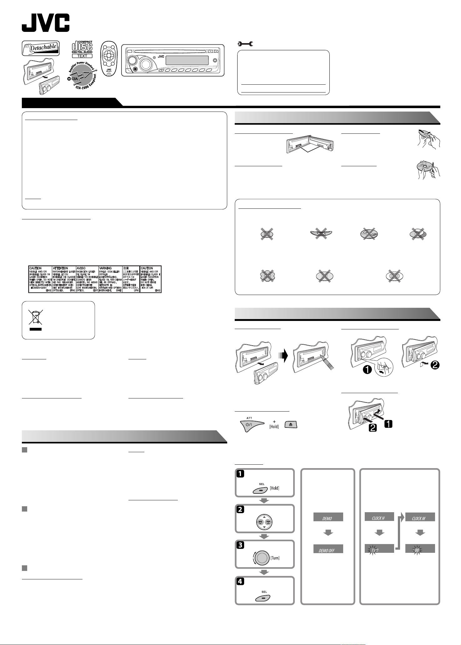
MAINTENANCE
How to clean the connectors
Wipe the connectors with
a cotton swab or cloth
moistened with alcohol.
Moisture condensation
Moisture may condense on the lens inside the unit. Eject
the disc and leave the unit turned on for a few hours until
the moisture has evaporated.
Do not use the following discs:
Single CD—8 cm (3-3/16”) disc
Unusual shape
Connectors
Warped disc Sticker and sticker residue Stick-on label
C-thru Disc (semi-transparent disc)
To keep discs clean
Wipe in a straight line from center of disc to
edge. Do not use liquid cleaners, thinners, or
benzene.
To play new discs
Remove any rough areas from the inner and
outer edges of the disc.
Transparent or semi-transparent
parts on its recording area
[European Union only]
For safety...
• Do not raise the volume level too much, as this will block
outside sounds, making driving dangerous.
• Stop the car before performing any complicated
operations.
Temperature inside the car...
If you have parked the car for a long time in hot or cold
weather, wait until the temperature in the car becomes
normal before operating the unit.
MORE ABOUT THIS UNIT
Basic operations
• By pressing SRC on the unit, you can also turn on the
power. If the source is ready, playback also starts.
• If you turn off the power while listening to a disc, disc
play will start from where it had been stopped previously
next time you turn on the power.
• When no disc is loaded in the unit, you cannot select “CD”
as the playback source.
Tuner operations
• During SSM search...
– All previously stored stations are erased and the
stations are stored anew.
– Received stations are preset in No. 1 (lowest
frequency) to No. 6 (highest frequency).
– When SSM is over, the station stored in No. 1 will be
automatically tuned in.
Disc operations
Caution for DualDisc playback
• The Non-DVD side of a “DualDisc” does not comply with
the “Compact Disc Digital Audio” standard. Therefore, the
use of Non-DVD side of a DualDisc on this product may
not be recommended.
Warning
If you need to operate the unit while driving, be sure to
look around carefully or you may be involved in a traffic
accident.
Caution on volume setting
Discs produce very little noise compared with other sources.
Lower the volume before playing a disc to avoid damaging
the speakers by the sudden increase of the output level.
General
• This unit has been designed to reproduce CDs/CD Texts,
and CD-Rs (Recordable)/CD-RWs (Rewritable) in audio CD
(CD-DA).
• After ejecting a disc, “NO DISC” appears and you cannot
operate some of the buttons. Insert another disc or press
SRC to select another playback source.
Playing a CD-R or CD-RW
• Use only “finalized” CD-Rs or CD-RWs.
• This unit can play back multi-session discs; however,
unclosed sessions will be skipped while playing.
• Some CD-Rs or CD-RWs may not be played back on this
unit:
– Discs are dirty or scratched.
– Moisture condensation has occurred on the lens inside
the unit.
– The pickup lens inside the unit is dirty.
– The files on the CD-R/CD-RW are written using the
“Packet Write” method.
– There are improper recording conditions (missing data,
etc.) or media conditions (stained, scratched, warped,
etc.).
• CD-RWs may require a longer readout time since the
reflectance of CD-RWs is lower than that of regular CDs.
PREPARATIONS
How to reset your unit
Reset the unit after installation is complete.
• Your preset adjustments will also be erased.
How to forcibly eject a disc
• Be careful not to drop the disc when it ejects.
• If this does not work, reset your unit.
Basic settings
Enter PSM menu.
Select an item.
Adjust.
Finish
Cancel the display
demonstration
Deactivate the display
demonstration.
Detaching the control panel
Attaching the control panel
Set the clock
Adjust the hour. Adjust the minute.
Page 2
2 – EN
INSTRUCTIONS
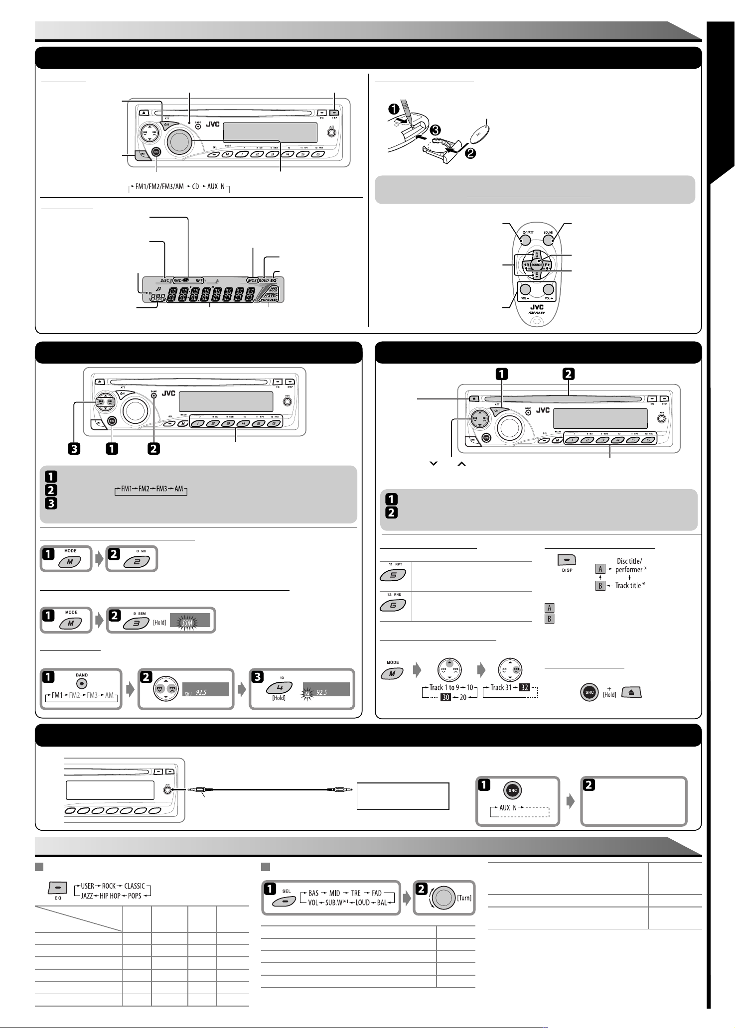
OPERATIONS
Basic operations
Control panel
• Turn on the power.
• Turn off the power [Hold].
• Attenuate the sound (if the
power is on).
Detach the panel.
Display window
Playback mode / item indicator
Disc indicator
Tr (track) indicator
• Source display
• Track number
• Volume level indicator
• Time countdown indicator
Radio operations
Remote sensor
DO NOT expose to strong light.
Select the source.
Main display (time,
playback information)
Check the current clock time/other information.
See also “CLK DISP“ of “General settings—PSM.”
Volume control.
• MO: Lights up in monaural mode.
• ST: Lights up when receiving an FM stereo
broadcast with sufficient signal strength.
LOUD (loudness) indicator
EQ (equalizer) indicator
Sound mode (iEQ: intelligent equalizer)
indicator
Remote controller—RM-RK50
7 Installing battery
Warning: To prevent accidents and damage
Lithium coin battery (CR2025)
For USA-California Only: This product contains a CR Coin Cell Lithium Battery which contains Perchlorate Material—
special handling may apply. See www.dtsc.ca.gov/hazardouswaste/perchlorate
• Do not install any battery other than CR2025 or its
equivalent.
• Store out of reach of children.
• Do not recharge, short, or dismantle.
• Do not dispose of in fire.
• Do not carry around with other metallic materials.
7 Features
• Turns the power on if pressed briefly or
attenuates the sound when power is on.
• Turns the power off if pressed and held.
• Changes the FM/AM bands with 5 U.
• Changes the preset stations with D ∞.
• Adjusts the volume level.
• Selects the sound mode
(iEQ: intelligent equalizer).
• Selects the source.
• Searches for stations if pressed briefly.
• Fast-forwards or reverses the track if
pressed and held.
• Changes the track of the disc if pressed
briefly.
Disc operations
Select preset station.
• You can also use 5 / ∞ to select preset station.
Select “FM/AM.”
Select the bands.
Search for a station—Auto Search.
Manual Search: Hold either one of the buttons until “M” flashes on the display, then press it repeatedly.
When an FM stereo broadcast is hard to receive
Reception improves, but the stereo effect will be lost.
• MO indicator lights up.
To restore the stereo effect, repeat the same procedure.
FM station automatic presetting —SSM (Strong-station Sequential Memory)
You can preset six stations for each band.
Manual presetting
Example: Storing the FM station of 92.5 MHz into preset number 4 of the FM1 band.
Eject disc.
• Press SRC to
listen to another
playback source.
4 / ¢
•
[Press] Go to the next or previous track.
[Hold] Fast-forwards or reverses the track.
Turn on the power.
Insert disc.
All tracks will be played repeatedly until you change the source or eject the disc.
Selecting the playback modes
After pressing M MODE, press the following buttons to...
TRK RPT : Plays the current track
RPT OFF : Cancels.
ALL RND : Plays all tracks of the current
RND OFF : Cancels.
repeatedly.
disc at random.
Skipping a track quickly during play
Example: Select track 32
[Press] Select track number (01 – 06).
[Hold] Select track number (07 – 12).
Changing the display information
: Clock with the current track number
: The elapsed playing time with the current track
number
If the current disc is an audio CD, “NO NAME” appears.
*
Prohibiting disc ejection
You can lock a disc in the loading slot.
External component operations
Stereo mini plug (not supplied)
SETTINGS
Sound adjustments
Preset values
Indication (For)
USER (Flat sound) 00 00 00 OFF
(Rock or disco music) +03 00 +02 OFF
ROCK
CLASSIC (Classical music) +01 00 +03 OFF
(Light music) +02 +01 +02 OFF
POPS
HIP HOP
(Funk or rap music) +04 –02 +01 OFF
(Jazz music) +03 00 +03 OFF
JAZZ
BAS
(bass)
MID
(mid-range)
(treble)
TRE
LOUD
(loudness)
Portable audio player, etc.
Adjusting the sound
BAS*2 (bass) : Adjust the bass. –06 to +06
MID*2 (mid-range) : Adjust the middle frequencies sound level. –06 to +06
TRE*2 (treble) : Adjust the treble. –06 to +06
3
(fader) : Adjust the front and rear speaker balance. R06 to F06
FAD*
BAL (balance) : Adjust the left and right speaker balance. L06 to R06
To cancel the prohibition, repeat the same procedure.
You can connect an external component to the AUX (auxiliary) input jack on the
control panel.
Turn on the connected
component and start
playing the source.
4
LOUD*
(loudness) : Boost low and high frequencies to
SUB.W (subwoofer) :
VOL (volume) : Adjust the volume. 00 to 50
*1 Displayed only when “L/O MODE” is set to “WOOFER.”
2
When you adjust the bass, mid-range, or treble, the adjustment you have made
*
is stored for the currently selected sound mode (iEQ) including “USER.”
*3 If you are using a two-speaker system, set the fader level to “00.”
4
*
The adjustment made (LOUD ON/LOUD OFF) will be applied to all sound modes
(iEQ).
*5 Depending on the amplifier gain control setting.
produce a well-balanced sound at
a low volume level.
Adjust the subwoofer output level.
LOUD ON or
LOUD OFF
00 to 08
(or 00 to 30)*
See reverse page \
5
Page 3

3 – EN
General settings—PSM
Select an item. Adjust. FinishEnter PSM menu.
Indication Item ( : Initial) Setting
DEMO • DEMO ON
• DEMO OFF
1
CLK DISP *
CLOCK H (Hour) 1 – 12 : [Initial: 1 (1:00)]
CLOCK M (Minute) 00 – 59 : [Initial: 00 (1:00)]
DIMMER • ON
SCROLL • ONCE
L/O MODE • REAR
WOOFER *
AUX ADJ A.ADJ 00
AMP GAIN *
• ON
• OFF
• OFF
• AUTO
• OFF
• WOOFER
2
• LOW
• MID
• HIGH
– A.ADJ 05
3
• LOW PWR
• HIGH PWR
: The display demonstration will be activated automatically if no operation is
done for about 20 seconds.
: Cancels.
:
The clock time is shown on the display at all times when the power is turned
off
.
: Cancels; pressing DISP will show the clock time for about 5 seconds when the
power is turned off.
: Dims the display and button illumination.
: Cancels.
: Scrolls the displayed information once.
: Repeats scrolling (at 5-second intervals).
: Cancels.
• Pressing DISP for more than one second can scroll the display regardless of
the setting.
: Select if the REAR LINE OUT terminals are used for connecting the speakers
(through an external amplifier).
: Select if the REAR LINE OUT terminals are used for connecting a subwoofer.
: Frequencies lower than 90 Hz are sent to the subwoofer.
: Frequencies lower than 135 Hz are sent to the subwoofer.
: Frequencies lower than 180 Hz are sent to the subwoofer.
: Adjust the auxiliary input level to avoid the sudden increase of the output
level when changing the source from external component connected to the
AUX input jack on the control panel.
: VOL 00 – VOL 30 (Select if the maximum power of each speaker is less than
50 W to prevent the speaker from being damaged.)
: VOL 00 – VOL 50
SPECIFICATIONS
Audio amplifier section
Power Output:
20 W RMS × 4 Channels at 4
≤ 1% THD+N
Signal to Noise Ratio:
80 dBA (reference: 1 W into 4
Load Impedance: 4 Ω (4 Ω to 8 Ω allowance)
Tone Control Range: Bass: ±12 dB at 60 Hz
Mid-range: ±12 dB at 1 kHz
Treble: ±12 dB at 7.5 kHz
Frequency Response: 40 Hz to 20 000 Hz
Line-Out Level/Impedance: 2.5 V/20 kΩ load (full scale)
Output Impedance: 1 k
Subwoofer-Out Level/Impedance:
2.5 V/20 kΩ load (full scale)
Tuner section
Frequency Range:
FM: 87.5 MHz to 107.9 MHz
(with channel interval set to 100 kHz or 200 kHz)
87.5 MHz to 108.0 MHz
(with channel interval set to 50 kHz)
AM: 530 kHz to 1 710 kHz
(with channel interval set to 10 kHz)
531 kHz to 1 602 kHz
(with channel interval set to 9 kHz)
[FM Tuner]
Usable Sensitivity: 11.3 dBf (1.0 μV/75 Ω)
50 dB Quieting Sensitivity: 16.3 dBf (1.8 μV/75
Alternate Channel Selectivity (400 kHz): 65 dB
Frequency Response: 40 Hz to 15 000 Hz
Stereo Separation: 35 dB
[AM Tuner]
Sensitivity/Selectivity: 20 μV/35 dB
Ω
and
Ω
)
Ω
Ω
)
CD player section
Type: Compact disc player
Signal Detection System: Non-contact optical pickup
Number of channels: 2 channels (stereo)
Frequency Response: 5 Hz to 20 000 Hz
Dynamic Range: 93 dB
Signal-to-Noise Ratio: 98 dB
Wow and Flutter: Less than measurable limit
(semiconductor laser)
General
Power Requirement: Operating Voltage:
(11 V to 16 V allowance)
Grounding System: Negative ground
Allowable Operating Temperature:
0°C to +40°C (32°F to 104°F)
Dimensions (W × H × D):
Installation Size (approx.):
182 mm × 52 mm × 160 mm
(7-3/16” × 2-1/16” × 6-5/16”)
Panel Size (approx.):
188 mm × 58 mm × 5 mm
(7-7/16” × 2-5/16” × 1/4”)
Mass (approx.):
1.3 kg (2.9 lbs) (excluding accessories)
Design and specifications are subject to change without
notice.
If a kit is necessary for your car, consult your telephone
directory for the nearest car audio speciality shop.
DC 14.4 V
Having TROUBLE with operation?
Please reset your unit
Still having trouble??
Call 1-800-252-5722 (USA ONLY)
http://www.jvc.com
INSTRUCTIONS
AREA • AREA US
• AREA EU
• AREA SA
1
*
If the power supply is not interrupted by turning off the ignition key of your car, it is recommended that you select “OFF” to
save the car’s battery.
2
Displayed only when “L/O MODE” is set to “WOOFER.”
*
3
*
The volume level automatically changes to “VOL 30” if you change to “LOW PWR” while the volume level is set higher than
“VOL 30.”
: When using in North/Central/South America. AM/FM intervals are set to
10 kHz/200 kHz.
: When using in any other areas. AM/FM intervals are set to 9 kHz/50 kHz
(100 kHz during auto search).
: When using in South American countries. AM/FM intervals are set to 10 kHz/
100kHz.
TROUBLESHOOTING
Symptoms Remedies/Causes
• Sound cannot be heard from the speakers. • Adjust the volume to the optimum level.
• The buttons on the unit do not work as you
General
intended.
• This unit does not work at all. Reset the unit.
• SSM automatic presetting does not work. Store stations manually.
FM/AM
• Static noise while listening to the radio. Connect the antenna firmly.
• Disc ejects. Insert the disc correctly.
• CD-R/CD-RW cannot be played back.
• Tracks on the CD-R/CD-RW cannot be
skipped.
• Disc can be neither played back nor ejected. • Unlock the disc.
• Disc sound is sometimes interrupted. • Stop playback while driving on rough roads.
Disc playback
• Check the cords and connections.
If you press M MODE, some buttons work differently from it
original function. Wait for 5 seconds or press M MODE again.
• Insert a finalized CD-R/CD-RW.
• Finalize the CD-R/CD-RW with the component which you used
for recording.
• Eject the disc forcibly.
• Change the disc.
• Check the cords and connections.
PREPARATION
You need the installation kits which corresponds to your car.
• Mark all the check boxes ( ) to make sure you have follow the instructions and the listed parts.
Check the battery system in your car
12 V DC, NEGATIVE ground
Prepare this before installation
TROUBLESHOOTING
• The fuse blows.
* Are the red and black leads connected correctly?
• Power cannot be turned on.
* Is the yellow lead connected?
• No sound from the speakers.
* Is the speaker output lead short-circuited?
• Sound is distorted.
* Is the speaker output lead grounded?
* Are the “–” terminals of L and R speakers grounded in common?
• Noise interfere with sounds.
* Is the rear ground terminal connected to the car’s chassis using shorter and thicker cords?
• This unit becomes hot.
* Is the speaker output lead grounded?
* Are the “–” terminals of L and R speakers grounded in common?
• This unit does not work at all.
* Have you reset your unit?
• “NO DISC” appears on the display.
• “PLEASE” and “EJECT” appear alternately
on the display.
• Microsoft and Windows Media are either registered trademarks or trademarks of Microsoft Corporation in the United
States and/or other countries.
Insert a playable disc into the loading slot.
Page 4

4 – EN
INSTALLATION / CONNECTION
Parts list for installation and connection
A
Control panel
G
E
Washer (ø5)
F
Lock nut (M5)
Mounting bolt—
M4 x 5 mm (M4 x 1/4");
M5 x 12.5 mm (M5 x 1/2")
INSTALLATION
If you are not sure how to install this unit correctly, consult your JVC car audio dealer.
In dash-mounting
When you stand the unit, be careful not to
damage the fuse on the rear.
Do the required electrical
connections.
B
Sleeve
C
Trim plate
H
Rubber cushion
Before removing the unit, release the rear section.
I
Handles
D
Power cord
J
Remote controller
Removing the unit
K
Battery
Bend the appropriate tabs
to hold the sleeve firmly
in place.
When installing the unit without using the sleeve
Flat type screws
—M5 × 8 mm (M5 × 3/8")*
Bracket*
Dashboard
When using the optional stay
Fire wall
Stay (option)
Screw (option)
Install the unit at an angle of
less than 30˚.
In a Toyota car for example, first remove the car radio and install the unit in its place.
Flat type screws—M5 × 8 mm (M5 × 3/8")*
Bracket*
Pocket
ELECTRICAL CONNECTIONS
Make sure to disconnect the battery’s negative terminal.
• Be sure to ground this unit to the car’s chassis again after installation.
Note:
It is recommended to connect to the speakers with maximum power of more than 50 W (both at the rear and at the front, with an impedance of 4 Ω to 8 Ω). If the
maximum power is less than 50 W, change “AMP GAIN” setting to prevent the speakers from being damaged (see page “General setting — PSM“ of the INSTRUCTIONS.).
Typical connections Connecting the external amplifier or subwoofer
Rear line out
Rear ground terminal
High
Remote lead
* Not supplied for this unit.
Heat sink
Y-connector *
1
Antenna
terminal
Connect only the front speakers if your
speaker system is two-speaker system.
White with black stripe
Front speaker (left)
Front speaker (right)
Rear speaker (left)
Rear speaker (right)
White
Gray with black stripe
Gray
Green with black stripe
Green
Purple with black stripe
Purple
15 A fuse
Black
2
Yellow *
Red
Blue with white
stripe
To the metallic body
or chassis of the car
To a live terminal in the
fuse block connecting to the
car battery (bypassing the
ignition switch) (constant
12 V)
To an accessory terminal in
the fuse block
To the remote lead of other
equipment or automatic antenna if
any (200 mA max.)
Ignition switch
Fuse block
Set “L/O MODE” to “REAR”
(See “General settings—PSM.”)
You can connect a power amplifier for
rear speakers.
JVC Amplifier
Rear
speakers
Set “L/O MODE” to “WOOFER”
(See “General settings—PSM.”)
You can also connect a subwoofer to
the REAR LINE OUT terminals.
JVC Amplifier
Subwoofer
or
PRECAUTIONS on power supply and speaker connections
Remote lead (blue with white stripe)
To the remote lead of other equipment
or automatic antenna if any
Right
Left
1
Not supplied for this unit.
*
*2 Before checking the operation of this unit prior to installation, this
lead must be connected, otherwise the power cannot be turned on.
*3 Firmly attach the ground wire to the metallic body or to the chassis
of the car—to the place uncoated with paint (if coated with paint,
remove the paint before attaching the wire). Failure to do so may
cause damage to the unit.
*4 Signal cord (not supplied for this unit)
Front speakers
 Loading...