

Page 1
LCD DISPLAY
LCD
GD-30L1G
English
INSTRUCTIONS
For Customer Use:
Enter below the Model No. and the Serial
No. which is located on the rear panel of the
cabinet. Retain this information for future
reference.
Model No.
Serial No.
15503741
Page 2

Table of Contents
Important Information .......................................................................................... 1
Safety Precautions, Maintenance, & Recommended Use ......................................... 2
Contents ............................................................................................................. 3
Attaching LCD Options ........................................................................................ 4
Parts Name and Functions
Control Panel .......................................................................................... 5
Terminal Panel ........................................................................................ 6
Wireless Remote Control .......................................................................... 7
Operating Range for the Remote Control................................................... 8
Handling the Remote Control.................................................................... 8
Setup Procedure ................................................................................................. 9
Connections
Wiring Diagram .................................................................................. 10
Connecting to a PC.............................................................................. 11
Connecting to a Macintosh Computer ................................................... 12
Connecting to a Computer with a Digital Output .................................... 13
Connecting to a VCR or Laser Disc Player.............................................. 14
Connecting to a DVD Player ................................................................. 15
Connecting to a Stereo Amplifier .......................................................... 16
Basic Operation
Power On and Off Modes ........................................................................ 17
Power Indicator ....................................................................................... 18
When Using Power Management Function ................................................ 18
Selecting a Video Source ......................................................................... 18
Picture Size ............................................................................................. 18
Picture Mode........................................................................................... 18
OSD Information ..................................................................................... 18
Control Key Lock Mode ............................................................................ 18
OSD (On-Screen Display) Controls
Computer ............................................................................................... 19
DVD & HD .............................................................................................. 23
AV input ................................................................................................. 25
About REMOTE-PIP Mode ........................................................................ 27
Using the LCD with a Personal Computer (PC) ....................................................... 28
Troubleshooting .................................................................................................. 30
Specifications ..................................................................................................... 31
Page 3
Important Information
TO PREVENT FIRE OR SHOCK HAZARDS, DO NOT EXPOSE THIS UNIT TO RAIN OR MOISTURE. ALSO, DO NOT USE THIS UNIT'S
POLARIZED PLUG WITH AN EXTENSION CORD RECEPTACLE OR OTHER OUTLETS UNLESS THE PRONGS CAN BE FULLY INSERTED.
REFRAIN FROM OPENING THE CABINET AS THERE ARE HIGH VOLTAGE COMPONENTS INSIDE. REFER SERVICING TO QUALIFIED
SERVICE PERSONNEL.
WARNING
CAUTION
CAUTION:TO REDUCE THE RISK OF ELECTRIC SHOCK, MAKE SURE POWER CORD IS UNPLUGGED FROM WALL SOCKET. TO FULLY
DISENGAGE THE POWER TO THE UNIT, PLEASE DISCONNECT THE POWER CORD FROM THE AC OUTLET. DO NOT REMOVE
COVER (OR BACK). NO USER SERVICEABLE PARTS INSIDE. REFER SERVICING TO QUALIFIED SERVICE PERSONNEL.
This symbol warns user that uninsulated voltage within the unit may have sufficient magnitude to cause electric shock. Therefore, it is
dangerous to make any kind of contact with any part inside this unit.
This symbol alerts the user that important literature concerning the operation and maintenance of this unit has been included. Therefore,
it should be read carefully in order to avoid any problems.
Canadian Department of Communications Compliance Statement
DOC: This Class B digital apparatus meets all requirements of the Canadian Interference-Causing Equipment Regulations.
C-UL: Bears the C-UL Mark and is in compliance with Canadian Safety Regulations according to CAN/CSA C22.2 No.
60950.
FCC Information
1.
Use the following specified cables with the GD-30L1G so as not to interfere with radio and television reception.
(1)
Please use the supplied power cord or equivalent to ensure compliance with FCC requirements.
(2) Please use a shielded RGB signal cable* which has ferrite cores on each end of the cable to ensure compliance with FCC
requirements.
* mini D-sub 15 pin to mini D-sub 15 pin cable for RGB2 (D-SUB) and DVI-D cable for RGB1 (DVI-D). Please see pages
11–13 of this manual.
(3) P
lease attach the ferrite cores on the Audio Cable and S -VIDEO cable.
Please see page 10 of this manual.
2.
This equipment has been tested and found to comply with the limits for a Class B digital device, pursuant to part 15 of the FCC
Rules. These limits are designed to provide reasonable protection against harmful interference in a residential installation. This
equipment generates, uses, and can radiate radio frequency energy, and, if not installed and used in accordance with the
instructions, may cause harmful interference to radio communications. However, there is no guarantee that interference will
not occur in a particular installation. If this equipment does cause harmful interference to radio or television reception, which
can be determined by turning the equipment off and on, the user is encouraged to try to correct the interference by one or more
of the following measures:
• Reorient or relocate the receiving antenna.
• Increase the separation between the equipment and receiver.
• Connect the equipment into an outlet on a circuit different from that to which the receiver is connected.
• Consult your dealer or an experienced radio/TV technician for help.
English
DECLARATION OF CONFORMITY
This device complies with Part 15 of FCC Rules. Operation is subject to the following two conditions. (1) This device may not cause
harmful interference, and (2) this device must accept any interference received, including interference that may cause undesired
operation.
CAUTION: Changes or modifications not approved by JVC could void user’s authority to operate the equipment.
U.S. Responsible Party: JVC Professional Products Company
Address: 1700 Valley Road Wayne,
New Jersey 07470, U.S.A.
Tel. No.: (973) 317-5000
Type of Product: Computer Monitor
Equipment Classification: Class B Peripheral
Model: GD-30L1G
We hereby declare that the equipment specified above
conforms to the technical standards as specified in the FCC Rules.
English-1
Page 4

Safety Precautions, Maintenance & Recommended Use
Safety Precautions and Maintenance
FOR OPTIMUM PERFORMANCE, PLEASE NOTE THE FOLLOWING WHEN
SETTING UP AND USING THE GD-30L1G:
• DO NOT OPEN THE DISPLAY. There are no user serviceable parts
inside and opening or removing covers may expose you to dangerous shock hazards or other risks. Refer all servicing to qualified service personnel.
• Do not spill any liquids into the cabinet or use your display near
water.
• Do not insert objects of any kind into the cabinet slots, as they
may touch dangerous voltage points, which can be harmful or
fatal or may cause electric shock, fire or equipment failure.
• Do not place any heavy objects on the power cord. Damage to
the cord may cause shock or fire.
• Do not place this product on a sloping or unstable cart, stand or
table, as the display may fall, causing serious damage to the
display.
• Use a power supply cord that matches with the power supply
voltage of the AC power outlet being used.
• Do not place any objects onto the display and do not use the
display outdoors.
• The inside of the fluorescent tube located within the LCD
display contains mercury.
• Do not bend power cord.
• Do not use display in high temperature, humid, dusty, or oily areas.
• If glass is broken, handle with care.
• Do not cover vent on display.
• If display or glass is broken, do not come in contact with the liquid
crystal and handle with care.
• Allow adequate ventilation around the display so that heat can
properly dissipate. Do not block ventilated openings or place the
display near a radiator or other heat sources. Do not put anything on top of display.
• The power cable connector is the primary means of detaching the
system from the power supply. The display should be installed
close to a power outlet which is easily accessible.
• Handle with care when transporting. Save packaging for
transporting.
•Please follow the bylaws or rules of your municipality to
dispose of the tube properly.
• Keep the holes on the back of the LCD clean of dirt and dust.
It is recommended to wipe holes with a soft cloth a minimum of
once per year.
Recommended Use
CAUTION
CORRECT PLACEMENT AND ADJUSTMENT OF THE DISPLAY
CAN REDUCE EYE, SHOULDER AND NECK FATIGUE. CHECK
THE FOLLOWING WHEN YOU POSITION THE DISPLAY:
• For optimum performance, allow 20 minutes for warm-up.
• Rest your eyes periodically by focusing on an object at least
20 feet away. Blink often.
• Position the display at a 90˚ angle to windows and other light
sources to minimize glare and reflections. Adjust the display
tilt so that ceiling lights do not reflect on your screen.
• If reflected light makes it hard for you to see your screen, use
an antiglare filter.
• Clean the LCD display surface with a lint-free, nonabrasive
cloth. Avoid using any cleaning solution or glass cleaner.
• Adjust the display’s back light and contrast controls to enhance readability.
• Position whatever you are looking at most of the time (the
screen or reference material) directly in front of you to minimize turning your head while you are typing.
•Avoid displaying fixed patterns on the display for long periods of time to avoid image persistence (afterimage effects).
• Get regular eye checkups.
• The lamp of backlight contains mercury. Please handle it appropriately in case of disposal.
Ergonomics
To r ealize the maximum ergonomics benefits, we recommend the
following:
• Use the preset Size and Position controls with standard
signals
• Use the preset Color Setting
• Use non-interlaced signals with a vertical refresh rate between
58-62Hz
• Do not use primary color blue on a dark background, as it is
difficult to see and may produce eye fatigue to insufficient
contrast
CAUTION
Immediately unplug your display from the wall outlet and refer
servicing to qualified service personnel under the following
conditions:
• When the power supply cord or plug is damaged.
• If liquid has been spilled, or objects have fallen into the display.
• If the display has been exposed to rain or water.
• If the display has been dropped or the cabinet damaged.
• If the display does not operate normally by following operating
instructions.
English-2
Page 5
REMOTE
CONTROLLER RU-M107
INSTRUCTIONS
GD-30L1G
For Customer Use:
Enter below the Model No. and the Serial
No. which is located on the rear panel of the
cabinet. Retain this information for future
reference.
Model No.
Serial No.
LCD DISPLAY
Part No. 15503292
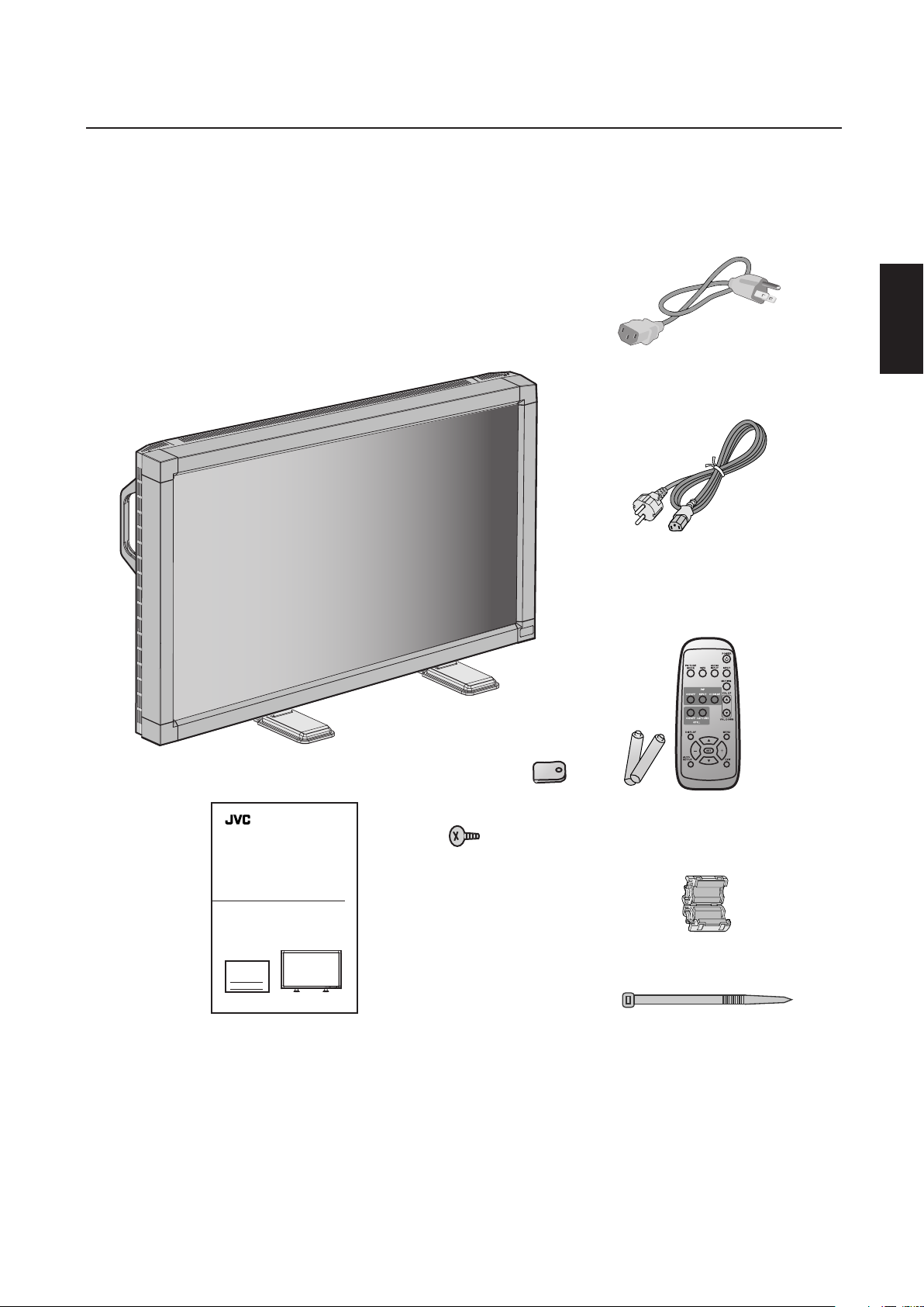
Contents
Your new GD-30L1G display box* should contain the following:
• GD-30L1G LCD display with stand
• Power Cord x 2 (Use the one matching the wall outlet)
• Instructions
• Wireless Remote Control and AA Batteries
• Clamper x 2
• Screw (M4 x 10) x 2
• Ferrite Core x 2
• Band
English
Power Cord
(for USA and Canada)
Power Cord (for Asia)
Clamper x 2
Screw (M4 x 10 ) x 2
Instructions
*Remember to save your original box and packing material to transport or ship the display.
The following component is prepared as an option.
• External Speakers (AS-D30L1G)
Wireless Remote Control
and AA Batteries
Ferrite Core x 2
Band
English-3
Page 6
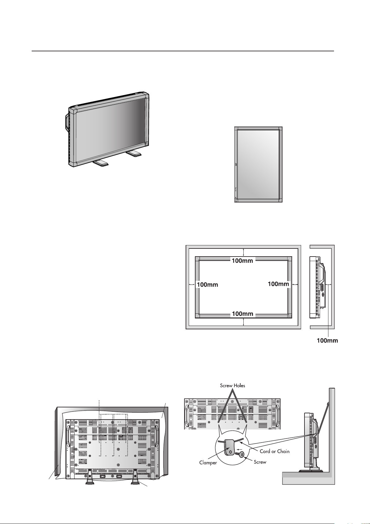
Attaching LCD Options
EXIT MUTINGINPUT
You can attach mounting accessories to the LCD display in one of
the following two ways:
1. In the upright position
2. Lay the screen face down
To avoid damaging the screen face, place the protective sheet on the
table to lay the LCD on. The protective sheet was wrapped around
the LCD in the original packaging.
This device cannot be used or installed without the Tabletop Stand or
other mounting accessory. For proper installation it is strongly recommended to use a trained, JVC authorized service person. Failure
to follow JVC standard mounting procedures could result in damage to the equipment or injury to the user or installer. Product warranty does not cover damage caused by improper installation. Failure to follow these recommendations could result in voiding your
warranty.
Caution:
• This unit does not stand stable without the tabletop stands.
Use the mounting accesories (not supplied) to install it without the
tabletop stands.
For details, refer to the instruction manual of the mounting
accesories.
• When display is installed in the portrait position, left edge should
be upper from front view.
Ventilation Requirements for enclosure
mounting
To allow heat to disperse, leave space between surrounding
objects as shown in the diagram to the right.
*
When using mounting accessories, they must be compatible with
®
Flat Display Mounting Interface Standard FOR 23“ TO 30.9“
VESA
DIAGONAL Flat Displays (Hole Pattern 200 mm x 100 mm). JVC
strongly recommends using screws M4 size and 8mm in length. If
using screws longer than 8mm, check the depth of the hole. (Recommended Fastern Force: 150 - 170N•cm)
JVC recommends using mounting interface that comply with UL1678
standard in North America.
When using the mounting accesories, screw the mouting
accessories in the rear of the display.
Hole Pattern:
200 mm x 100 mm (by using 6 screws)
Screw holes (for using 6 screws)
*Ambient temperature should be less than 40 deg C
To avoid falling down
Fasten the LCD display to a wall using a cord or chain which is
sufficient to support the weight of the LCD display (approx. 16kg).
Ta bl e
Ta bletop Stand
Before moving the LCD display, the cord or chain should be removed.
English-4
Page 7

Parts Name and Functions
1
2
3
4
5
6
7
8
9
Control Panel
English
POWER button ( )
Switches the power on/off. See also page 17.
MUTING button
Switches the audio muting ON/OFF.
INPUT button
Acts as SET button with OSD menu.
Selects the signal connected with the RGB input connector.
(Toggle switches between [RGB1], [RGB2], [RGB3], [DVD/HD],
or [VIDEO].)
PLUS (+) button
Acts as (+) button to increase the adjustment with OSD menu.
Increase the audio output level when the OSD menu is turned
off.
MINUS (-) button
Acts as (-) button to decrease the adjustment with OSD menu.
Decrease the audio output level when the OSD menu is turned
off.
Button Location
DOWN ( ) button
Activates the OSD menu when the OSD menu is turned-off.
Acts as button to move the highlighted area down to select
the adjustment with OSD menu.
EXIT button
Activates the OSD menu when the OSD menu is turned-off.
Acts as EXIT button to move to previous menu with OSD menu.
Remote control sensor and Power indicator
Receives the signal from the remote control (when using the
wireless remote control). See also page 8.
Glows green when the LCD display is in active and glows red
when the LCD is in POWER OFF mode. When the LCD is in
power save mode, it will glow both green and red.
Main Power Switch
10
Seesaw Switch for the main power on/off.
UP ( ) button
Activates the OSD menu when the OSD menu is turned-off.
Acts as button to move the highlighted area up to select the
adjustment with OSD menu.
English-5
Page 8
1
8
9
5
6
7
4 3 2
10
1
2
3
4
5
6
7
8
9
Parts Name and Functions –continued
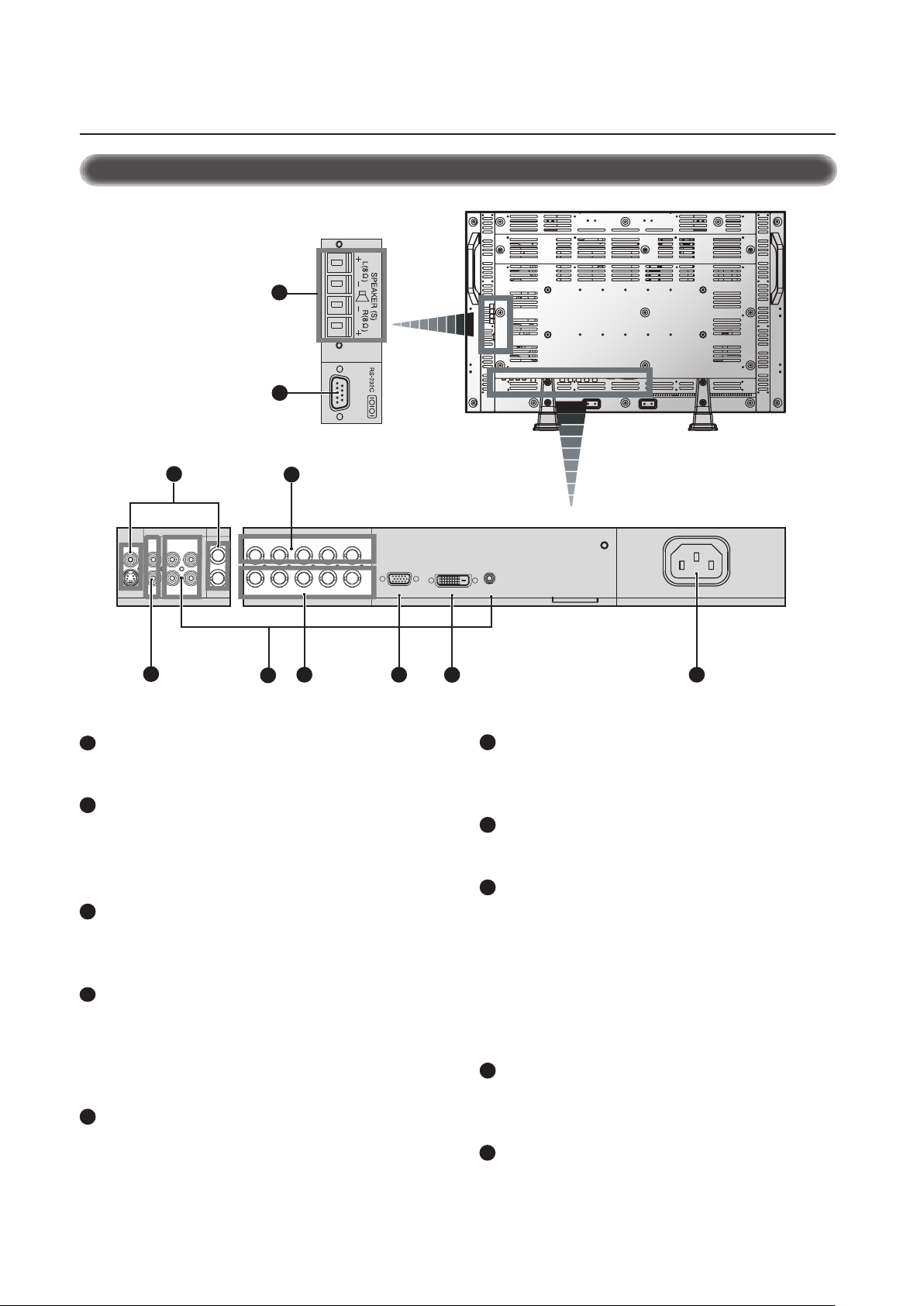
Terminal Panel
AC IN connector
Connects with the supplied power cord.
RGB1(DVI-D)
To input digital RGB signals from a computer having a digital RGB
output.
* This connector does not support analog input.
RGB2(D-SUB) (mini D-Sub 15 pin)
To input a analog RGB signals from a personal computer or other
RGB equipment.
RGB3 DVD/HD IN (BNC)
To input the analog RGB signals or signals from other RGB
equipment. Also for connecting equipment such as a DVD player
or HDTV laser disc player. A Sync-on-Green signal
can be connected to the G/Y connector.
RGB OUT (BNC)
To output the signal from the RGB2(D-SUB) or RGB3 DVD/HD IN
connector.
AUDIO1, 2, 3
To input audio signal from external equipment such as a computer,
VCR or DVD player.
AUDIO OUT
To output the audio signal from the AUDIO3 jack.
VIDEO
VIDEO IN connector (BNC and RCA): To input a composite video
signal. BNC and RCA are not available at the same time.
(Use only one input).
VIDEO OUT connector (BNC): To output the composite video
signal from the VIDEO IN connector.
S-VIDEO IN connector (DIN 4 pin): To input the S-video (Y/C
separate signal).
RS-232C (mini D-Sub 9 pin)
Use when operating the LCD display from the RGB equipment like
a computer.
10
SPEAKER(S)
External speaker terminal.
To output the audio signal from AUDIO1, 2 or 3 jack.
English-6
Page 9

REMOTE
CONTROLLER RU-M107
345
2
6
7
8
19
11
12
16
13
14
17
15
18
10
9
1
1
2
3
4
5
Parts Name and Functions –continued
6
7
8
Wireless Remote Control
VOLUME UP button
Increase the audio output level.
VOLUME DOWN button
Decrease the audio output level.
9
PIP (Picture In Picture) button
ON/OFF button: Toggle switches between PIP-ON/
POP-ON/OFF.
INPUT button: Select the ‘picture in picture’ input signal.
CHANGE button: Replaces to the main picture and sub
picture.
English
POWER button
Switches the power on/off.
* If Power Indicator is not glowing, then no controls will work.
INPUT button
Selects from input signal, [RGB1], [RGB2], [RGB3], [DVD/
HD], [VIDEO].
AUDIO INPUT button
Selects from input audio signal, [AUDIO1], [AUDIO2],
[AUDIO3]
SIZE button
Selects picture size, [FULL], [NORMAL], [WIDE]. See page 18.
PICTURE MODE button
Selects from picture mode, [HIBRIGHT], [STANDARD], [sRGB],
[CINEMA].
HIBRIGHT: for moving image such as DVD
STANDARD: for images
sRGB: for text based images
CINEMA: for movies. See page 18.
MUTING button
To on/off the muting function.
10
STILL button
ON/OFF button: To on/off the still picture mode.
CAPTURE button: Capture the new picture.
11
DISPLAY button
To on/off the OSD information. See page 18.
12
AUTO SETUP button
To enter the auto setup menu. See page 21.
13
MENU button
To on/off the menu mode.
14
UP button
Acts as button to move the highlighted area up to select the
adjustment with OSD menu.
Small screen which adjusted “PIP” mode moves up.
15
DOWN button
Acts as button to move the highlighted area down to select
the adjustment with OSD menu.
Small screen which adjusted “PIP” mode moves down.
16
MINUS button decrease
Acts as (-) button to decrease the adjustment with OSD menu.
Small screen which adjusted “PIP” mode moves left.
17
PLUS button increase
Acts as (+) button to increase the adjustment with OSD menu.
Small screen which adjusted “PIP” mode moves right.
18
SET button
Acts as SET button with OSD menu.
19
EXIT button
Turn to previous menu with OSD menu.
English-7
Page 10
Parts Name and Functions –continued
30o30
o
REMOTE
CONTROLLER RU-M107
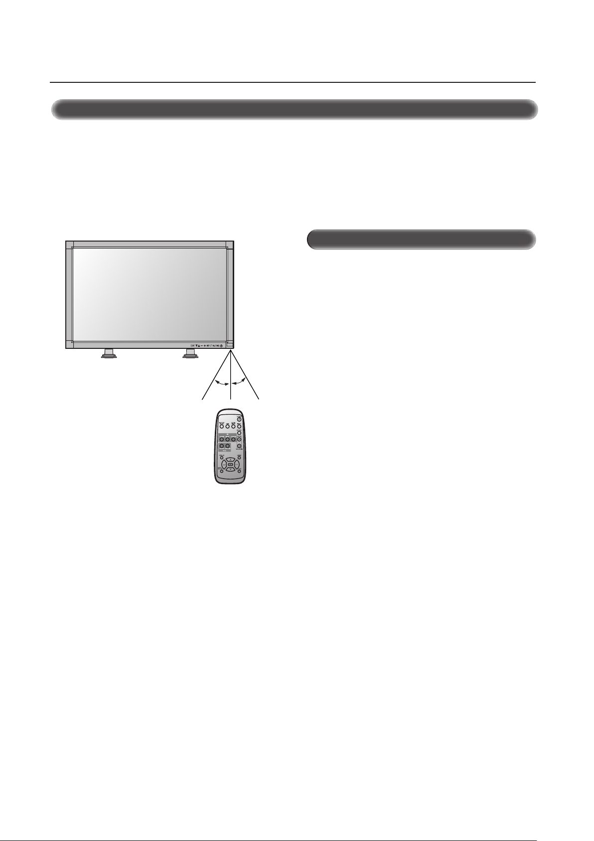
Operating Range for the Remote Control
Point the top of the remote control toward the LCD display's remote sensor during button operation.
Use the remote control within a distance of about 7 m/23 ft. from
the front of the LCD display's remote control sensor and at a horizontal and vertical angle of within 30° within a distance of about
3 m/10 ft.
Caution
The remote control system may not function when direct sunlight
or strong illumination strikes the remote control sensor of the LCD
display, or when there is an object in the path.
Handling the Remote Control
* Other than to install the batteries, do not open the remote
control.
Do not allow water or other liquid to splash onto the remote
*
control. If the remote control gets wet, wipe it dry immediately.
*Avoid exposure to heat and steam.
English-8
Page 11
Setup Procedure
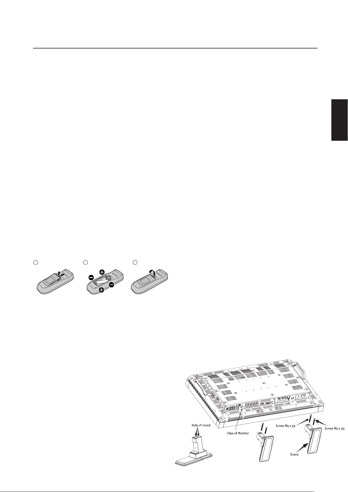
Remove the cover
1
Insert the batteries Replace the cover
3
2
1. Determine the installation location
CAUTION
Installing your LCD display must be done by a qualified technician. Contact your dealer for more information.
CAUTION
MOVING OR INSTALLING THE LCD DISPLAY MUST BE DONE BY
TWO OR MORE PEOPLE. Failure to follow this caution may result
in injury if the LCD display falls.
CAUTION
Do not mount or operate the display upside down, face up or face
down.
IMPORTANT
Lay the protective sheet, which was wrapped around the LCD display when it was packaged, beneath the LCD display so as not to
scratch the panel.
2. Install the remote control batteries
The remote control is powered by 1.5V AA batteries. To install or
replace batteries:
1. Press and slide to open the cover.
2. Align the batteries according to the (+) and (–) indications
inside the case.
3. Replace the cover.
CAUTION
Incorrect usage of batteries can result in leaks or bursting. JVC
recommends the following battery use:
• Place "AA" size batteries matching the + and - signs on each
battery to the + and - signs of the battery compartment.
• Do not mix battery brands.
• Do not combine new and old batteries. This can cause a
shorten life or liquid leakage of batteries.
• Remove dead batteries immediately to prevent battery acid
from leaking into the battery compartment. Don't touch exposed battery acid, it cause damage to your skin.
NOTE: If you do not intend to use the Remote Control for a
long period, remove the batteries.
3. Connect external equipment (See page 10-16)
•To protect the connected equipment, turn off the main power
before making connections.
• Refer to your equipment user manual.
4. Connect the supplied power cord
• The equipment should be installed close to a power outlet and
should be easily accessible.
• Fully insert the prongs into the power outlet socket. Loose connection may cause image degradation.
• Use a power supply cord that matches with the power supply
voltage of the AC power outlet being used.
5. Switch on the power of all the attached
external equipment
When connected with a computer, switch on the power of the
computer first.
6. Operate the attached external equipment
Display the signal on the external equipment you wish.
7. Adjust the sound
Make adjustments when adjustment of the volume is required.
8. Adjust the screen (See pages 19-27)
Make adjustments when adjustment of the screen display
position.
9. Adjust the image (See page 19-27)
Make adjustments when picture adjustment such as the backlight
or contrast is required.
10. When display is installed in the portrait
position
• Remove the stand (feet).
• Left edge should be upper from front view.
11. When installing the display to a wall
How to remove the stand
1. Spread the protective sheet on the flat surface, such as
a desk.
2. Place display on the protective sheet.
3. Remove 2 screws by screwdriver and place them in a safe
place for reuse.
How to install stand
1. Please turn display off.
2. Insert claws of display to stand holes until clicks.
3. Fasten 2 screws on both sides of the display.
Upper M5 x 55mm Lower M5 x 45mm
Torque 280 - 300N•cm.
English
English-9
Page 12

Connections
LCD display (second display)
LCD display
display
display.
display
display.
Before making connections:
* First turn off the power of all the attached equipment and make connections.
* Refer to the user manual included with each separate piece of equipment.
Wiring Diagram
English-10
Page 13

LCD display (second display)
LCD display
Connections
–continued
Connecting to a PC
Connecting your computer to your LCD display will enable you to display your computer's screen image.
Some video cards may not display an image correctly.
•To connect the RGB2 (D-SUB) connector (mini D-sub 15 pin) on the LCD display, use a shielded RGB signal cable which has ferrite cores
on each end of the cable as it is illustrated below (mini D-sub 15 pin to mini D-sub 15 pin)(not supplied.)
•To connect the RGB3 DVD/HD IN connector (BNC) on the LCD display, use a signal cable (mini D-sub 15 pin to BNC x 5)(not supplied.)
Select RGB3 from the INPUT button.
When connecting one or more LCD displays, use the RGB OUT connector (BNC).
• The AUDIO1, 2 and 3 can be used for audio input. For connection, select AUDIO1, 2 or 3 from the AUDIO INPUT button.
English
English-11
Page 14

LCD display (second display)
LCD display
Connections
–continued
Connecting to a Macintosh® Computer
Connecting your Macintosh® computer to your LCD display will enable you to display your computer's screen image. Some video cards or
drivers may not display images correctly.
•To connect the RGB2 (D-SUB) connector (mini D-sub 15 pin) on the LCD display, use a shielded RGB signal cable which has ferrite cores
on each end of the cable as it is illustrated below (mini D-sub 15 pin to mini D-sub 15 pin) (not supplied.)
For older Macintosh
•To connect the RGB3 DVD/HD IN connector (BNC) on the LCD display, use a signal cable (mini D-sub 15 pin to BNC x 5)(not supplied.)
• If you use with a Macintosh PowerBook, set "Mirroring" to off.
Refer to your Macintosh's owner's manual for more information about your computer's video output requirements and any special
identification or configuring your display's image and display may require.
• The AUDIO1, 2 and 3 can be used for audio input. For connection, select AUDIO1, 2 or 3 from the AUDIO INPUT button.
®
computers, use Macintosh cable adapter to connect to your Macintosh's video port.
English-12
Page 15
LCD display
Connections
–continued
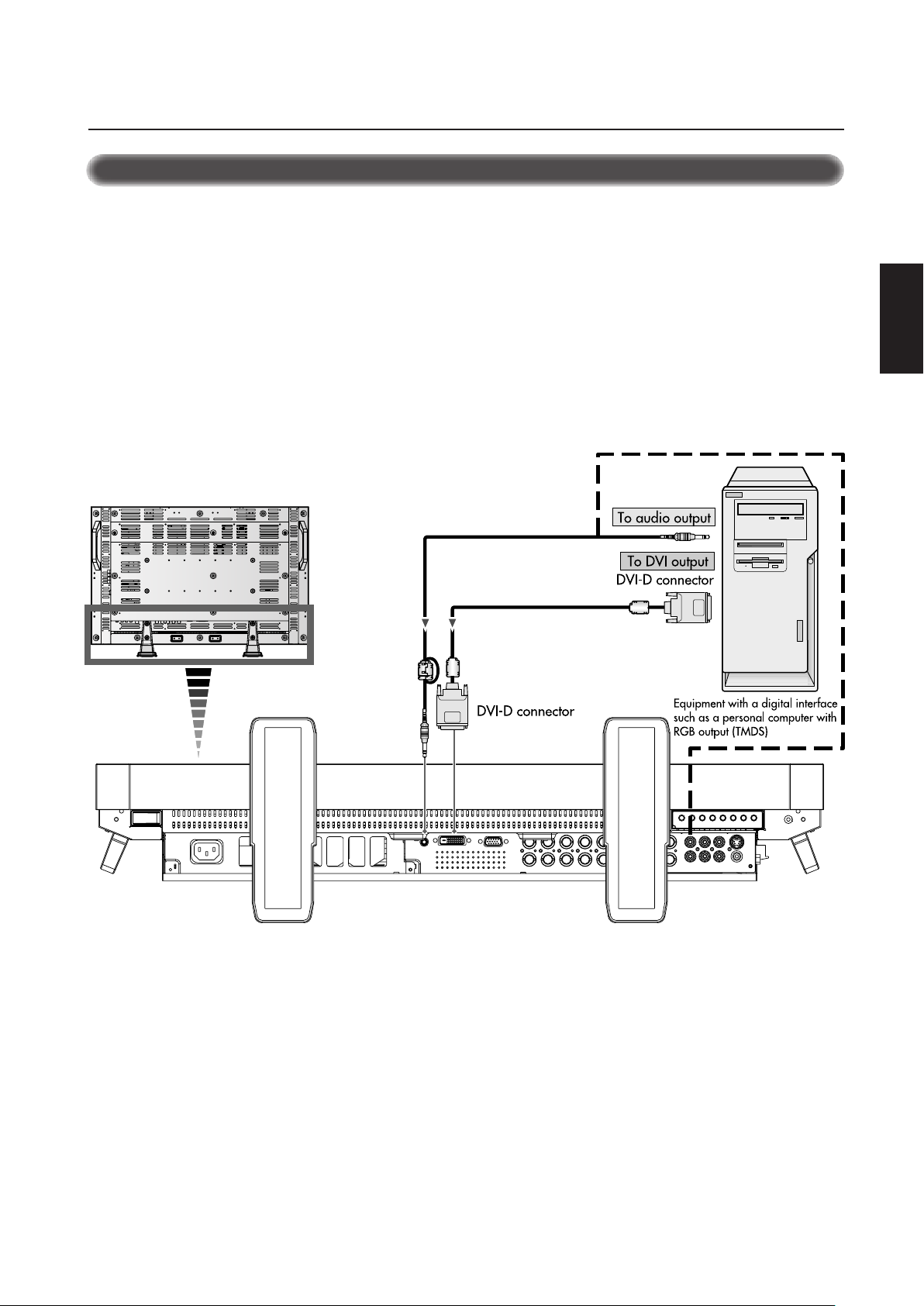
Connecting to a Computer with a Digital Output
Connections can be made with equipment that is equipped with a digital interface compliant with the DVI (Digital Visual Interface)
standard.
• The RGB1 (DVI-D) connector also accepts a Shielded DVI-D cable which has ferrite cores on each end of the cable as it is illustrated
below (not supplied.)
• Input TMDS signals conforming to DVI standards.
•To maintain display quality, use a cable recommended by DVI standards.
• The AUDIO1, 2 and 3 can be used for audio input. For connection, select AUDIO1, 2 or 3 from the AUDIO INPUT button.
English
English-13
Page 16

LCD display
LCD display (second display)
Connections
–continued
Connecting to a VCR or Laser Disc Player
Connecting your VCR or laser disc player to your LCD display will enable you to display your VCR or laser disc player video.
Refer to your VCR or laser disc player owner's manual for more information.
•Video signals can be connected to either the VIDEO IN [RCA or BNC] or the S-VIDEO IN connector.
NOTE: If S-VIDEO IN and VIDEO IN (RCA or BNC) are both connected, S-VIDEO IN will have priority.
•Video output will be from the OUT connector that has been set here.
• When connecting one or more LCD displays, use the VIDEO OUT connectors (BNC).
• The AUDIO IN2 and 3 can be both used for audio input. For connection, select [AUDIO2] or [AUDIO3] from the AUDIO INPUT button.
English-14
Page 17

LCD display
LCD display (second display)
Connections
–continued
Connecting to a DVD Player
Connecting your DVD player to your LCD display will enable you to display your DVD video.
Refer to your DVD player owner’s manual for more information.
•To connect the RGB3 DVD/HD IN connector (BNC) on the LCD display, use a BNC connector cable (not supplied.) You will need a BNCto-RCA adapter to connect a DVD player with an RCA pin jack to the BNC connector cable (not supplied.)
Some DVD players may have different connectors, such as Cr/Pr, Y and Cb/Pb.
Select [DVD/HD] input mode from the INPUT button.
When connecting one or more LCD displays, use the RGB OUT connectors (BNC).
The AUDIO IN2 and 3 (both RCA) can be used for audio input. For connection, select [AUDIO2] or [AUDIO3] from the AUDIO INPUT
button.
English
English-15
Page 18

LCD display
Connections
–continued
Connecting to a Stereo Amplifier
You can connect your stereo amplifier to your LCD display. Refer to your amplifier owner's manual for more information.
•Turn on the LCD display and the amplifier only after all hookups have been made.
• Use on RCA cable (not supplied) to connect the AUDIO OUT connector (RCA) on the LCD display and the audio input on the amplifier.
• Do not reverse the audio left and right jacks.
• The AUDIO OUT jack outputs sound for the AUDIO IN3 only.
English-16
Page 19
Basic Operation
Main Power Switch
Power Button
REMOTE
CONTROLLER RU-M107
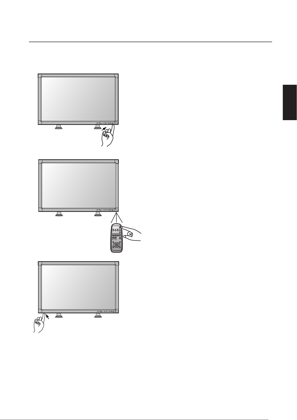
The LCD display power indicator will turn green while powered on or red in off mode. The display can be powered on or off using the
following three options:
– Power ON and OFF Modes
1. Pressing the power button.
NOTE: Before pressing the power button, be sure to turn
on the Main Power Switch on the LCD display.
2. Using the remote control
NOTE: Before operating the remote control, be sure to turn
on the Main Power Switch on the LCD display.
English
3. Pressing the Main Power Switch.
NOTE: When the Main Power Switch is used to power off
the LCD, the remote control and the power button will not
activate the on mode. Be sure to turn the Main Power
Switch to the on mode before using these two options.
English-17
Page 20

Basic Operation
– continued
Power Indicator
Power Indicator
Status
Power ON Green
Power OFF Red
Power Standby Red and Green
When Using Power Management Function
The LCD display follows the VESA approved DPMS Power Management function.
The power management function is an energy saving function that
automatically reduces the power consumption of the display when
the keyboard or the mouse has not been used for a fixed period of
time.
The power management feature on your new display has been set
to the “ON” mode. This allows your display to enter a Power
Saving Mode when no signal is applied. This could potentially
increase the life and decrease the power consumption of the display.
OSD Information
Selecting a Video Source
To view a video source:
Use the input button to set [VIDEO].
Use the COLOR SYSTEM menu to set, [AUTO], [NTSC], [PAL],
[SECAM], [PAL60], [4.43NTSC] according to your video format.
Picture Size
Picture Mode
Control Key Lock Mode
This control completely locks out access to all Control Key
functions after three (3) seconds.
To activate the control key lock function, press both of “ “ and
“ “ and hold down simultaneously.
To resume back to user mode, press both “ “ and “ “ and
hold simultaneously for three (3) seconds.
English-18
Page 21
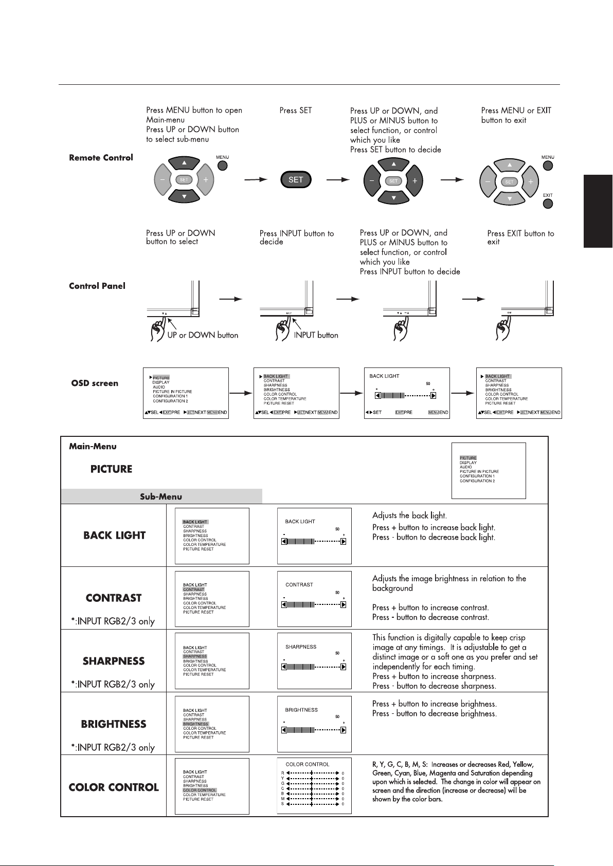
OSD (On-Screen Display) Controls
– Computer
English
English-19
Page 22
OSD Controls
– Computer continued
English-20
Page 23
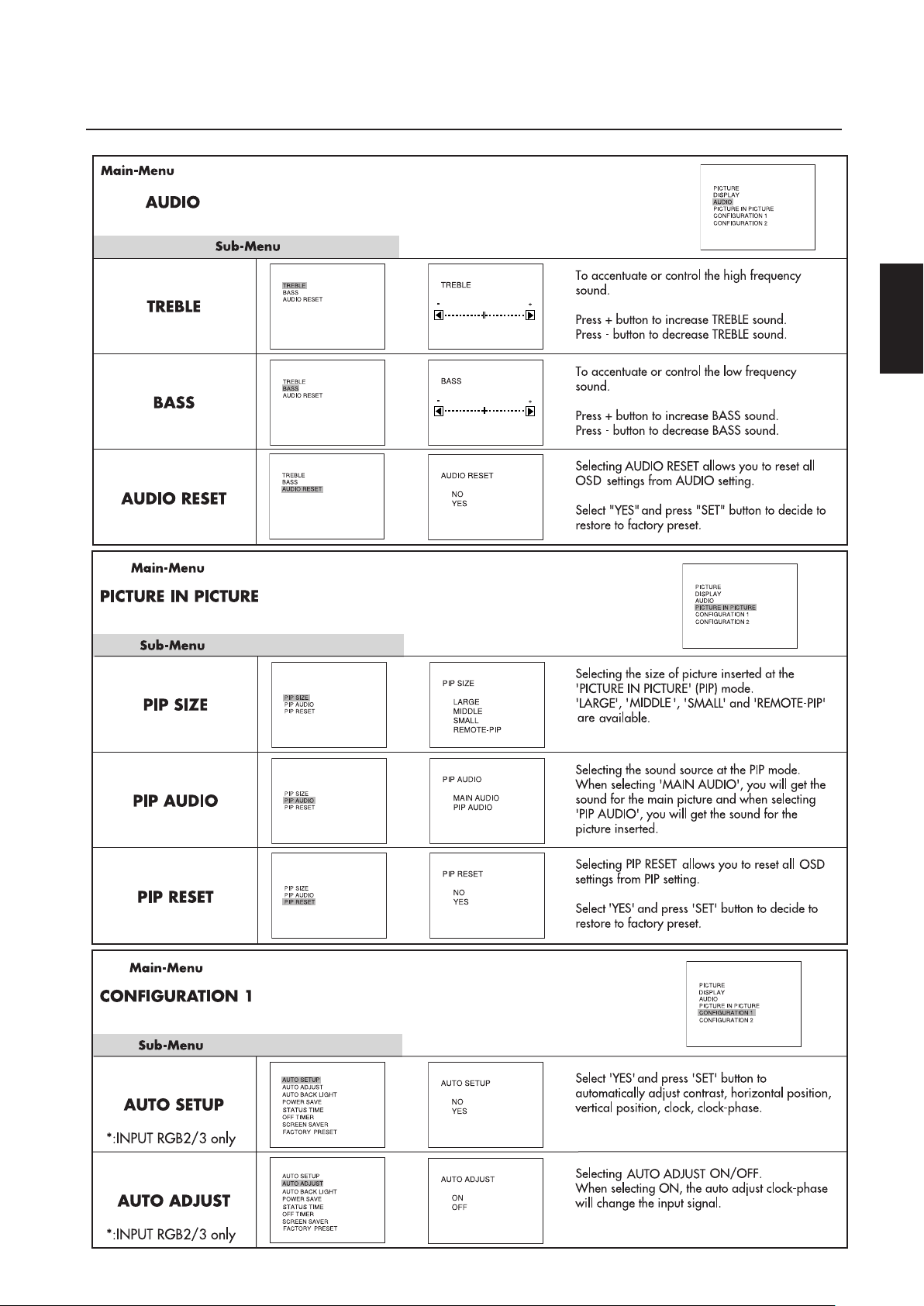
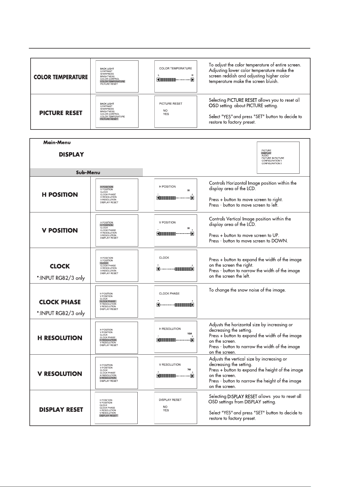
OSD Controls
– Computer continued
English
English-21
Page 24
OSD Controls
PRESET
– Computer continued
English-22
Page 25
OSD Controls
– DVD & HD
English
English-23
Page 26

OSD Controls
– DVD & HD continued
English-24
Page 27

OSD Controls
– AV Input
English
English-25
Page 28

OSD Controls
– AV Input continued
English-26
Page 29

OSD Controls
– AV Input continued
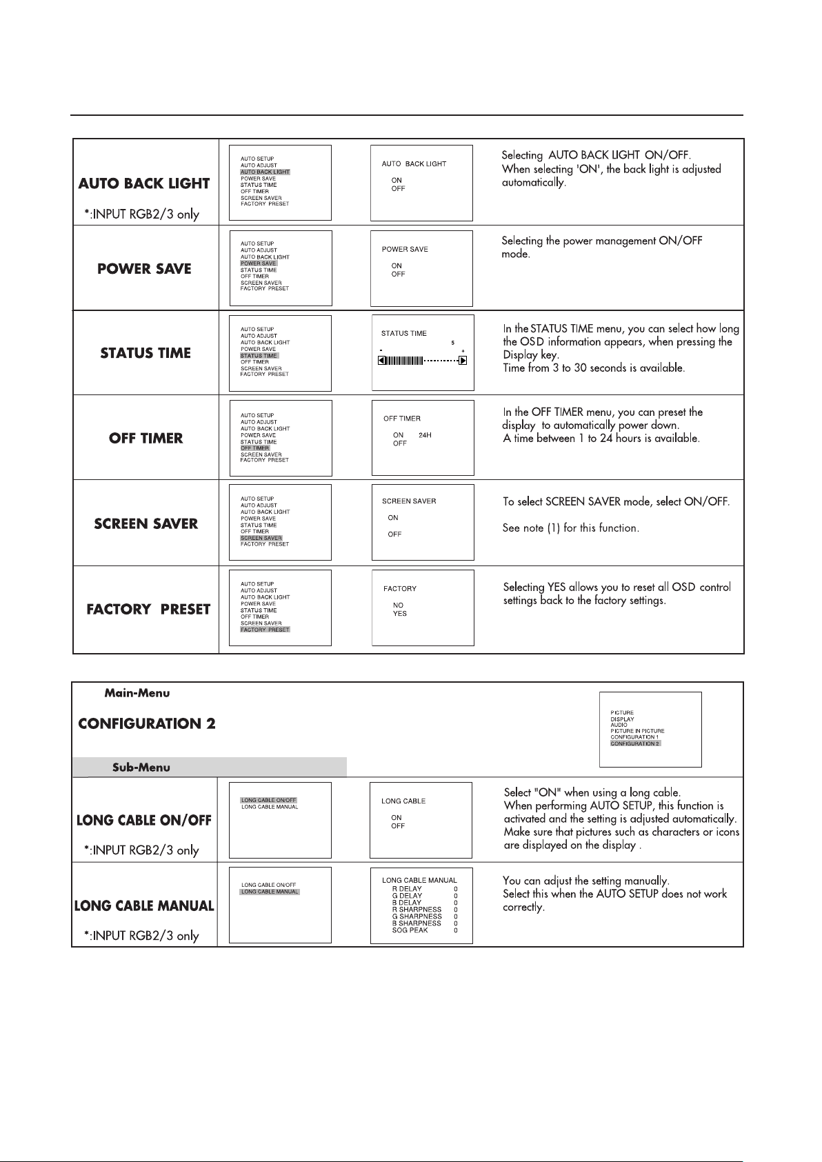
* Note (1) SCREEN SAVER
With this feature, the image displayed moves at incremental rate every 10 minutes and is not noticed by the end user. Please
be aware that LCD Technology may experience a phenomena known as Image Persistence. Image Persistence occurs when a
residual or “ghost” image of a previous image remains visible on the screen. Unlike CRT displays, LCD displays’ image
persistence is not permanent, but constant images being displayed for a long period of time should be avoided. To alleviate
image persistence, turn off the display for as long as the previous image was displayed. For example, if an image was on the
display for one hour and residual image remains, the display should be turned off for one hour to erase the image.
As with all personal display devices, JVC recommends displaying moving images and using a moving screen saver at regular
intervals whenever the screen is idle or turning off the display when not in use.
English
About REMOTE-PIP Mode
Remote PIP is a different function from normal PIP that can display PIP on particular color window on the desktop of PC and change
the size, position with the mouse.
Set your PC as follows:
®
(1) Open a new window (e.g. in Microsoft
The size of the picture box should be set to, 256 dot x 144 line, which is 12.864 cm (W) x 7.236 cm (H) or 512 dot x 384
line, which is 25.728 cm (W) x 19.296 cm (H)
(2) Set the window’s color to dark red (R=128, G=0, B=0).
There should not be any text, line, pattern, etc in the window.
Set your display as follows:
(3) Select ”PICTURE IN PICTURE“ on OSD.
(4) Select “PIP SIZE” on OSD.
(5) Select “REMOTE-PIP“ on OSD.
(6) Turn on PIP button on Remote Control.
(7) Sub picture is displayed in the new window on the PC.
(8) The size and position of the Sub Picture can be changed with the mouse.
Note: When REMOTE-PIP is selected, contrast and brightness of the display may change. REMOTE-PIP may not be displayed on
following cases:
• Gamma curve on PC’s display setting is changed.
• Contrast or brightness setting is changed from reset position on OSD.
In these cases, Please change the setting to reset position.
Office Excel) and create a picture box.
English-27
Page 30

display
Display
display
Using the LCD with a Personal Computer (PC)
English-28
Page 31

Using the LCD with a Personal Computer
ASCII HEX
Function Data(Receive) Function Data(Receive)
ON vP 1 76 50 31
Power
OFF(stand by)
vP 0 76 50 30
RGB- 1 (DV I-D) vI r1 76 49 72 31
RGB- 2 (D- SUB) vI r2 76 49 72 32
RGB- 3 (BNC) vI r3 76 49 72 33
Video vI v1 76 49 76 31
Input
DVD/HD
vI v2 76 49 76 32
HIBRIGHT vM p1 76 4D 70 31
Picture m od e
STANDARD
vM p2 76 4D 70 32
display
display
display
display
display
display
display
display
display
Display
Display
display
– continued
English
English-29
Page 32

Troubleshooting
No picture
• The signal cable should be completely connected to the display card/computer.
• The display card should be completely seated in its slot.
• Front Power Switch and computer power switch should be in the ON position.
• Check to make sure that a supported mode has been selected on the display card or system being used. (Please consult display card or
system manual to change graphics mode.)
• Check the display and your display card with respect to compatibility and recommended settings.
• Check the signal cable connector for bent or pushed-in pins.
Power Button does not respond
• Unplug the power cord of the display from the AC outlet to turn off and reset the display.
Image persistence
• Please be aware that LCD Technology may experience a phenomena known as Image Persistence. Image Persistence occurs when a
residual or “ghost” image of a previous image remains visible on the screen. Unlike CRT monitors, LCD displays’ image persistence is
not permanent, but constant images being displayed for a long period of time should be avoided.
To alleviate image persistence, turn off the display for as long as the previous image was displayed. For example, if an image was
on the display for one hour and a residual image remains, the display should be turned off for one hour to erase the image.
As with all personal display devices, JVC recommends displaying moving images and using a moving screen saver at regular
intervals whenever the screen is idle or turning off the display when not in use.
Image is unstable, unfocused or swimming is apparent
• Signal cable should be completely attached to the computer.
• Use the OSD screen controls to focus and adjust display by increasing or decreasing the clock phase total. When the display mode is
changed, the OSD Image Adjust settings may need to be readjusted.
• Check the display and your display card with respect to compatibility and recommended signal timings.
• If your text is garbled, change the video mode to non-interlace and use 60Hz refresh rate.
Image of component signal is greenish
• Check to see if the DVD/HD input connector is selected.
LED on display is not lit (no green or red color can be seen)
• Power Switch should be in the ON position and power cord should be connected.
• Make certain the computer is not in a power-saving mode (touch the keyboard or mouse).
Display image is not sized properly
• Use the OSD screen controls to increase or decrease the clock total.
• Check to make sure that a supported mode has been selected on the display card or system being used. (Please consult display card or
system manual to change graphics mode.)
Selected resolution is not displayed properly
• Use OSD information to enter Information menu and confirm that the appropriate resolution has been selected. If not, select corresponding option.
No Sound
• Check to see if speaker cable is properly connected.
• Check to see if muting is activated.
• Check to see if volume is set at minimum.
Remote Control is not available
•Test the Remote Control’s batteries for strength/life.
• Check if the batteries are inserted correctly.
• Check if the Remote Control is pointed at the display’s remote sensor.
Either light vertical or horizontal stripes may appear, depending on specific display patterns.
This is no product fault or degradation.
English-30
Page 33
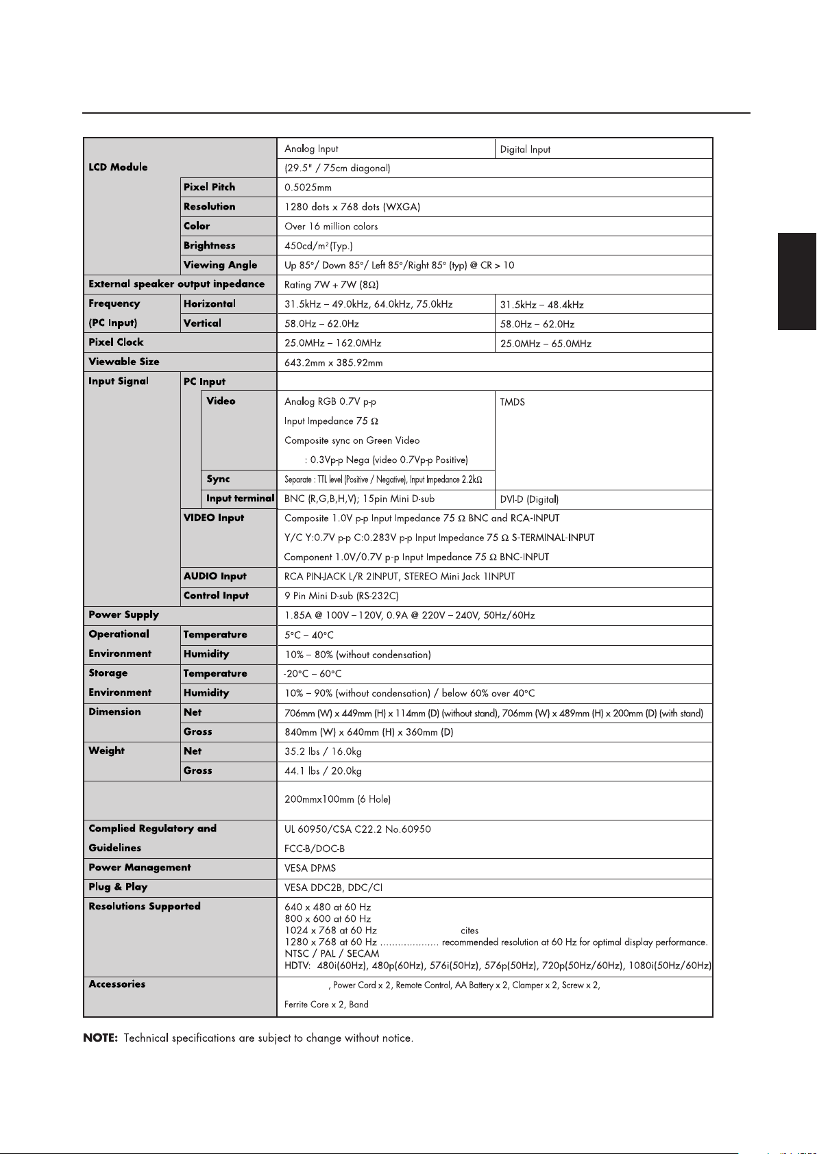
Specifications
JVC
Instructions
VESA Flat Display Mounting Interface
Standard FOR 23” TO 30.9”
DIAGONAL Flat Displays
English
Macintosh is resistered trademarks of Apple Computer, Inc.
Microsoft is registered trademarks of Microsoft Corporation.
All other product names mentioned herein are used for identification purposes only, and may be the trademarks or registered trademaks
of their respective companies.
English-31
Page 34

GD-30L1G LCD DISPLAY
© 2004 Victor Company of Japan, Limited
1104MKH-MW-NM
 Loading...