

Page 1
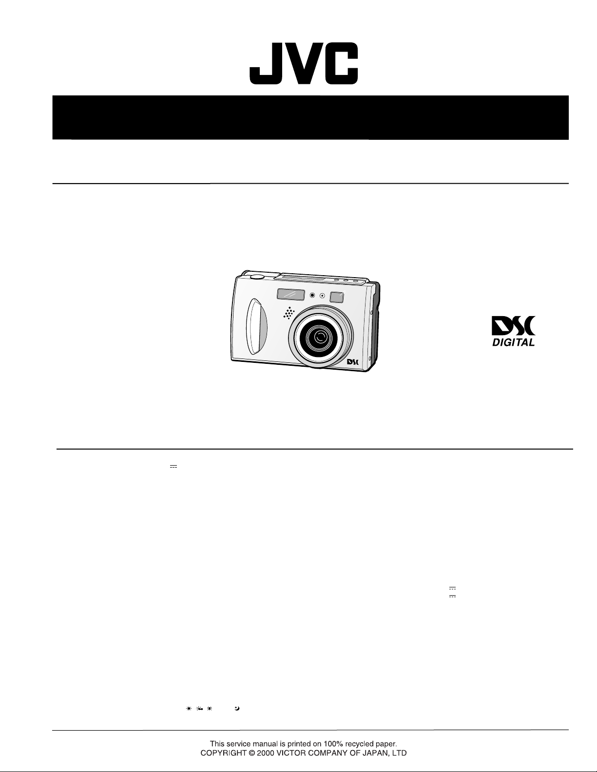
SERVICE MANUAL
DIGITAL STILL CAMERA
GC-X3E-DS
STILL CAMERA
Regarding service information other than these sections, refer to the GC-X1E service manual (No.86572). Also,
be sure to note important safety precautions provided in the service manual.
SPECIFICATIONS
Power source
Power consumption
Dimensions
Weight
Operating temperature
Relative humidity
Storage temperature
LCD screen
Storage media
CCD
Focal distance
Lens
Video
Recording format
Sensitivity
Iris value (F value)
Exposure control
Exposure compensation
Minimum subject distance
Light measurement system
Flash
Recommended distance for flash
Shutter speed
White balance
Focus
: DC 5 V
: 3.6 W (when the LCD screen is off)
4.8 W (when the LCD screen is on)
: 111 (W) mm x 67 (H) mm x 59 (D) mm
(except protruding parts)
: Approx. 290 g
(without a Memory card and battery)
:0°C to 40°C
: 35% to 80%
: –20°C to 50°C
: 2.0 inch, polysilicon TFT (200,000 pixels)
: SmartMedia
: 3.34 million pixels (3.24 million valid pixels),
1/1.8" square pixels, primary color filter,
interlace scan CCD
: 7.5 mm to 17.5 mm
(equivalent to 37mm to 86 mm on a 35 mm still camera)
: 2.3X optical zoom lens
: 160 pixels x 120 pixels, 20 seconds, JVC original format
: Exif Ver. 2.1 (DCF compliant), TIFF (Uncompressed),
DPOF-compatible
: 80/160/320 (ISO compliant)
: F2.8/3.8, 5.6, 8, 11
: Program AE, iris priority AE
: ±2EV (0.5EV steps)
: Approx. 2 cm to 50 cm (in Macro mode)
: Multi, spot
: Built-in,
Auto/red-eye prevention/forced/disabled
: Approx. 2.5 m
: Auto (Program AE: 1/8 seconds – 1/750 seconds,
Iris priority AE: 2 seconds – 1/750 seconds )
: Auto/Manual (
: Auto/Manual
TM
, MWB,
3.3V (up to 64MB)
, ,
)
Self timer
Photo quality
Number of storable photos
(with an 8MB Memory card,
STANDARD/FINE/NO COMP.)
Battery
Printer connector
VIDEO output connector
Digital output connector
: 1 second, 8 seconds
: 3 modes (STANDARD/FINE/NO COMP.)
: 2032 x 1536: approx. 10/8/0
1024 x 768: approx. 43/32/3
640 x 480: approx. 87/65/8
: Lithium ion battery
: Output for optional printer
: Two-pole plug, 3.5 mm diameter (PAL)
: Mini-USB connector
AC Power Adapter/Charger AA-V37
Power requirement
Power consumption
Output
Charge
Camera
Operating temperature
Dimensions
Weight
E. & O. E. Design and specifications subject to change without notice.
: AC 110 V – 240 V`, 50 Hz/60 Hz
: 14 W
: DC 3.6 V
: DC 5.0 V
:0°C to 40°C [when charging: 10°C to 35°C]
: 68 (W) mm x 38 (H) mm x 110 (D) mm
: Approx. 230 g (without a DC cord)
, 0.77 A
, 1.5 A
No.86593
October 2000
Page 2

Page 3

TABLE OF CONTENTS
Section Title Page
Important Safety Precautions
DIFFERENT TABLE
1. DISASSEMBLY
1.3.2 Disassembly method ( I ) ............................................ 1-1
2. ELECTRICAL ADJUSTMENT
2.1 ELECTRICAL ADJUSTMENT .......................................... 2-1
2.1.1 Precautions ................................................................. 2-1
Test instruments required for electrical adjustment .............
2.1.2
2-1
2.1.3 Required test equipment ............................................ 2-1
2.1.4 Setup (LCD ADJUSTMENT) ........................................ 2-1
2.1.5 Setup (CCD ADJUSTMENT) ....................................... 2-2
2.2 Setup with patch cords and jig connector cables............ 2-3
3. CHARTS AND DIAGRAMS
NOTES OF SCHEMATIC DIAGRAM ........................................ 3-1
CIRCUIT BOARD NOTES ......................................................... 3-2
3.1 BOARD INTERCONNECTION ......................................... 3-3
3.2 MAIN (SYSCON) SCHEMATIC DIAGRAM ...................... 3-5
3.3 MAIN (DSP146) SCHEMATIC DIAGRAM........................ 3-7
3.4 MAIN (DSP97) SCHEMATIC DIAGRAM.......................... 3-9
3.5 MAIN (CDS AGC A/D AND ARM ROM)
SCHEMATIC DIAGRAM ................... 3-11
3.6 MAIN (STROBE CONTROL AND AUDIO ) AND
STROBE FLASH SCHEMATIC DIAGRAMS........ 3-12
3.7 MAIN (F/Z_MDA / IRIS) SCHEMATIC DIAGRAM......... 3-13
JACK (VIDEO OUT/USB/PRINTER/DC JACK/
3.8
MONITOR BACK LIGHT) SCHEMATIC DIAGRAM ....
3-14
3.9 CCD SCHEMATIC DIAGRAM........................................ 3-15
3.10 MONI REG (MONITOR) SCHEMATIC DIAGRAM ......... 3-16
3.11 MONITOR REG (DC/DC) SCHEMATIC DIAGRAM........ 3-17
3.12 MAIN CIRCUIT BOARD ................................................ 3-19
3.13 MONITOR REG CIRCUIT BOARD................................. 3-25
3.16 JACK CIRCUIT BOARD ................................................. 3-27
3.18 CCD CIRCUIT BOARD .................................................. 3-29
STOROBE FLASH CIRCUIT BOARD .................................
3.20
3-31
3.22 OVER ALL BLOCK DIAGRAM....................................... 3-33
SOFTW ARE SECTION FOR Windows
Operating Environment
The host computer that runs the Windows
operating environment must satisfy the following
conditions.
USB Driver
®
1. Microsoft
2. Available USB port
3. CD-ROM drive
Video Player
1. CPU: Intel
2. Microsoft
3. Display capability of 65,536 colors or more
4. CD-ROM drive
5. Minimum RAM requirement: 32MB
6. Minimum hard disk space requirement: 1MB
* The system requirements information is not a
* Microsoft
* Intel
* Other trademarks are property of their respective
* If you use Windows
Windows® 98/Windows® 98 Second
Edition, Full version (Not Upgrade)/Windows
2000 Professional (Not Upgrade)
®
Pentium® 200MHz class or higher
®
Windows® 95/Windows® 98
guarantee that provided software applications will
work on all personal computers meeting those
requirements.
®
, Windows® are either registered
trademarks or trademarks of Microsoft corporation
in United States and/or other countries.
®
, Pentium® are registered trademarks of Intel
corporation.
owners.
which does not have a USB port, use an optional
flash path, conversion card adapter, etc. For
details on the operating environment of these
devices, contact the dealers or manufacturers.
®
95 or a personal computer
®
®
SOFTW ARE SECTION FOR Macintosh
Operating Environment
The host computer that runs the Macintosh
operating environment must satisfy the following
conditions.
USB Driver
1. USB-compatible computer (iMac™, iBook™,
®
Power Mac™ G3/G4, Power Book™ G3, etc.)
2. Mac OS 8.5.1/Mac OS 8.6/Mac OS 9.0
JVC Video Decoder
1. Power PC 603e/120MHz or faster
2. Mac OS 7.6.1 or later
3. QuickTime 3.0 or later
4. Minimum RAM requirement: 32MB
5. Minimum hard disk space requirement: 1MB
®
is a registered trademark of Apple
* Macintosh
Computer.
* Other trademarks are property of their respective
owners.
* If you use Macintosh
port, use an optional flash path, conversion card
adapter, etc. For details on the operating environment of these devices, contact the dealers or
manufacturers.
®
which does not have a USB
®
®
4. PARTS LIST
4.1 PACKING AND ACCESSORY ASSEMBLY <M1> ........... 4-1
4.3 FINAL ASSEMBLY <M2> .............................................. 4-3
4.4 ELECTRICAL PARTS LIST ............................................... 4-6
MAlN BOARD ASSEMBLY <01> .................................... 4-6
CCD BOARD ASSEMBLY <02>.................................... 4-11
MONI REG BOARD ASSEMBLY <03> ......................... 4-12
JACK BOARD ASSEMBLY <04> .................................. 4-14
STROBE FLASH BOARD ASSEMBLY <05> ................. 4-15
The following table indicate main different features between models GC-X1E, GC-X3E and GC-QX5HDU.
MODEL
ITEM
Installing the Film Copying Adapter NO YES
Shooting Film(Film Copy Mode) NO YES
GC-X1E GC-X3E
Page 4
The following table indicate different parts number between models GC-X1E, GC-X3E.
P ACKING ASSEMBL Y <M1>
REF NO.
1 PACKING CASE LY31465-003A LY32048-003A
4 SHEET LY42548-001A ––––
5 HOOD(OP) LY31822-001A ––––
5A POLY BAG QPA01001505 ––––
9 CD-ROM ASSEMBLY LY31074-010A LY31074-015A
13 FILM COPY ADAP. –––– LY20687-001A
14 FILM HOLDER AS –––– LY32047-001A
15 CUSHION(ACC) –––– LY32050-001A
! 31 INST.BOOK(EN) LYT0544-001C LYT0670-001A
! 32 INST.BOOK(FR) LYT0544-002A LYT0670-002A
! 33 INST.BOOK(SP) LYT0544-003A LYT0670-003A
ITEM
MODEL
GC-X1E
GC-X3E
Note : Mark –– is not used.
FINAL ASSEMBLY <M1>
REF NO.
103 BOARD HOLDER ASSEMBLY LY31457-002A LY31457-007B
107C SHEET LY30023-016A LY30023-016A
110 TOP COVER ASSEMBLY LY31460-002A LY31460-008B
111 OPERATION UNIT LY20521-002C LY20521-007B
113 SPACER(A) LY30029-016A ––––
118 MICROPHONE –––– LY31454-001A
130 SHEET –––– LY42890-001A
131 SPACER(A) –––– LY30029-0C2A
152 REAR COVER ASSEMBLY LY20519-002B LY20519-008B
153 FRONT COVER ASSEMBLY LYH20147-003A LYH20222-005A
153A FRONT COVER LY20516-002A LY20516-010A
153B GRIP LY42320-001A LY31444-002A
ITEM
MODEL
GC-X1E
GC-X3E
Note : Mark –– is not used.
OP BLOCK ASSEMBLY <M3>
REF NO.
203 OPTICAL BLOCK ASSEMBLY LY31490-001B LY31490-003A
221 TILT FRAME *LY20716-001A +
ITEM
MODEL
GC-X1E
GC-X3E
Note : Mark –– is not used.
Note : Mark * reference model was also changed.
Page 5
MAIN BOARD ASSEMBLY <01>
REF NO.
PW1 MAIN BOARD ASSEMBLY YB10282P-06 YB10299E-03
ITEM
MODEL
GC-X1E
GC-X3E
CCD BOARD ASSEMBLY <02>
REF NO.
PW1 MAIN BOARD ASSEMBLY YB10283P1-04 YB10300E1-02
ITEM
MODEL
GC-X1E
GC-X3E
MONI REG BOARD ASSEMBLY <03>
REF NO.
PW4
ITEM
MONI REG BOARD ASSEMBLY
MODEL
GC-X1E
YB10283P4-04 YB10300E4-02
GC-X3E
JACK BOARD ASSEMBLY <04>
REF NO.
PW2 JACK BOARD ASSEMBLY YB10283P2-04 YB10300E2-02
ITEM
MODEL
GC-X1E
GC-X3E
STROBE BOARD ASSEMBLY <05>
REF NO.
PW3 STROBE BOARD ASSEMBLY YB10283P3-04 YB10300E3-02
ITEM
MODEL
GC-X1E
GC-X3E
Page 6

Important Safety Precautions
Prior to shipment from the factory, JVC products are strictly inspected to conform with the recognized product safety and electrical codes
of the countries in which they are to be sold. However, in order to maintain such compliance, it is equally important to implement the
following precautions when a set is being serviced.
v
Precautions during Servicing
1. Locations requiring special caution are denoted by labels and
inscriptions on the cabinet, chassis and certain parts of the
product. When performing service, be sure to read and comply with these and other cautionary notices appearing in the
operation and service manuals.
2. Parts identified by the
critical for safety.
Replace only with specified part numbers.
Note: Parts in this category also include those specified to com-
ply with X-ray emission standards for products using
cathode ray tubes and those specified for compliance
with various regulations regarding spurious radiation
emission.
3. Fuse replacement caution notice.
Caution for continued protection against fire hazard.
Replace only with same type and rated fuse(s) as specified.
4. Use specified internal wiring. Note especially:
1) Wires covered with PVC tubing
2) Double insulated wires
3) High voltage leads
5. Use specified insulating materials for hazardous live parts.
Note especially:
1) Insulation Tape 3) Spacers 5) Barrier
2) PVC tubing 4) Insulation sheets for transistors
6. When replacing AC primary side components (transformers,
power cords, noise blocking capacitors, etc.) wrap ends of
wires securely about the terminals before soldering.
symbol and shaded ( ) parts are
12. Crimp type wire connector
In such cases as when replacing the power transformer in sets
where the connections between the power cord and power
transformer primary lead wires are performed using crimp type
connectors, if replacing the connectors is unavoidable, in order to prevent safety hazards, perform carefully and precisely
according to the following steps.
1) Connector part number : E03830-001
2) Required tool : Connector crimping tool of the proper type
which will not damage insulated parts.
3) Replacement procedure
(1) Remove the old connector by cutting the wires at a point
close to the connector.
Important : Do not reuse a connector (discard it).
cut close to connector
Fig.3
(2) Strip about 15 mm of the insulation from the ends of
the wires. If the wires are stranded, twist the strands to
avoid frayed conductors.
15 mm
Fig.1
7. Observe that wires do not contact heat producing parts
(heatsinks, oxide metal film resistors, fusible resistors, etc.)
8. Check that replaced wires do not contact sharp edged or
pointed parts.
9. When a power cord has been replaced, check that 10-15 kg of
force in any direction will not loosen it.
Power cord
Fig.2
10. Also check areas surrounding repaired locations.
11. Products using cathode ray tubes (CRTs)
In regard to such products, the cathode ray tubes themselves,
the high voltage circuits, and related circuits are specified for
compliance with recognized codes pertaining to X-ray emission.
Consequently, when servicing these products, replace the cathode ray tubes and other parts with only the specified parts.
Under no circumstances attempt to modify these circuits.
Unauthorized modification can increase the high voltage value
and cause X-ray emission from the cathode ray tube.
Fig.4
(3) Align the lengths of the wires to be connected. Insert
the wires fully into the connector.
Metal sleeve
Connector
Fig.5
(4) As shown in Fig.6, use the crimping tool to crimp the
metal sleeve at the center position. Be sure to crimp fully
to the complete closure of the tool.
1.25
2.0
5.5
Fig.6
(5) Check the four points noted in Fig.7.
Not easily pulled free
Wire insulation recessed
more than 4 mm
Fig.7
Crimping tool
Crimped at approx. center
of metal sleeve
Conductors extended
1
S40888-01
Page 7

v
d'
d
Chassis
Power cord,
primary wire
ab
c
V
Externally
exposed
accessible part
Z
Safety Check after Servicing
Examine the area surrounding the repaired location for damage or deterioration. Observe that screws, parts and wires have been
returned to original positions, Afterwards, perform the following tests and confirm the specified values in order to verify compliance with safety standards.
1. Insulation resistance test
Confirm the specified insulation resistance or greater between power cord plug prongs and
externally exposed parts of the set (RF terminals, antenna terminals, video and audio input
and output terminals, microphone jacks, earphone jacks, etc.). See table 1 below.
2. Dielectric strength test
Confirm specified dielectric strength or greater between power cord plug prongs and exposed
accessible parts of the set (RF terminals, antenna terminals, video and audio input and output
terminals, microphone jacks, earphone jacks, etc.). See table 1 below.
3. Clearance distance
When replacing primary circuit components, confirm specified clearance distance (d), (d’) between soldered terminals, and between terminals and surrounding metallic parts. See table 1
below.
Fig. 8
4. Leakage current test
Confirm specified or lower leakage current between earth ground/power cord plug prongs
and externally exposed accessible parts (RF terminals, antenna terminals, video and audio
input and output terminals, microphone jacks, earphone jacks, etc.).
Measuring Method : (Power ON)
Insert load Z between earth ground/power cord plug prongs and externally exposed accessible parts. Use an AC voltmeter to measure across both terminals of load Z. See figure 9 and
following table 2.
Fig. 9
5. Grounding (Class 1 model only)
Confirm specified or lower grounding impedance between earth pin in AC inlet and externally exposed accessible parts (Video in,
Video out, Audio in, Audio out or Fixing screw etc.).
Measuring Method:
Connect milli ohm meter between earth pin in AC inlet and exposed accessible parts. See figure 10 and grounding specifications.
AC inlet
Earth pin
AC Line Voltage
100 V
100 to 240 V
110 to 130 V
110 to 130 V
200 to 240 V
Exposed accessible part
Milli ohm meter
Fig. 10
Region
Japan
USA & Canada
Europe & Australia R 10 MΩ/500 V DC
Region Load Z
Insulation Resistance (R)
≤
R 1 MΩ/500 V DC
≥≥
1 MΩ R 12 MΩ/500 V DC
≤
Table 1 Specifications for each region
Grounding Specifications
Region
USA & Canada
Europe & Australia
Dielectric Strength
AC 1 kV 1 minute
AC 1.5 kV 1 miute
AC 1 kV 1 minute
AC 3 kV 1 minute
AC 1.5 kV 1 minute
(Class 2)
(Class 1)
Grounding Impedance (Z)
≤
Z 0.1 ohm
≤
Z 0.5 ohm
Clearance Distance (d), (d')
≤
d, d' 3 mm
≤
d, d' 4 mm
≤
d, d' 3.2 mm
≤
d 4 mm
≤
d' 8 mm (Power cord)
≤
d' 6 mm (Primary wire)
a, b, cLeakage Current (i)AC Line Voltage
100 V
110 to 130 V
110 to 130 V
220 to 240 V
Note: These tables are unofficial and for reference only. Be sure to confirm the precise values for your particular country and locality.
Japan
USA & Canada
Europe & Australia
Table 2 Leakage current specifications for each region
1 kΩ
0.15 µF
1.5 kΩ
2 kΩ
50 kΩ
2
≤
i 1 mA rms Exposed accessible parts
≤
i 0.5 mA rms
≤
i 0.7 mA peak
≤
i 2 mA dc
≤
i 0.7 mA peak
≤
i 2 mA dc
Exposed accessible parts
Antenna earth terminals
Other terminals
S40888-01
Page 8

Page 9

NOTE :
This service manual has indicated only the item different from GC-X1E-S No.86572.
1.3.2 Disassembly method ( I )
SECTION 1
DISASSEMBLY
STEP
1 FRONT CASE Remove screws
REAR CASE 2 (115), 3 (156), 4 (157), 1 (154)
2 OPERATION UNIT Remove the Connector Remove screws Note 1
3 STROBE BOARD ASSEMBLY Remove the Connector Remove screw Note 1
JACK BOARD ASSEMBLY Remove the Connector Remove screws
4 LCD MODULE Remove the Connector Remove screws Note 1
5 MAIN BOARD ASSEMBLY Remove the Connector Note 1
MONI/REG BOARD ASSEMBLY Remove the PWB HOLDER Remove screws 2 (114) Note 1
6 OP UNIT Remove from the Frame Assy Remove screws 3 (117)
PART NAME
Fig
1-3-1
Fig
1-3-1
Fig
1-3-2
Fig
1-3-3
r MAIN CN4001
Remove the TOP COVER 2 (115)
n MAIN CN6601
p MAIN CN5501
m LCD MODULE (BL)
k MAIN CN3002
Remove from the Frame Assy
Remove from the LCD Holder
h MAIN CN501
z MAIN CN2501
c MAIN CN3001
d MON/REG TL9001
OPERATION UNIT 3 (116)
STROBE CN6501 1 (114) Note 2
JACK CN101 2 (114)
LCD MODULE (LCD) 2 (114)
OP UNIT
MIC
MON/REG CN9001
Frame Assy d (SD1)
POINTFIG. NO.
JACK CN701 e (SD3), f (SD4), g (SD5)
Note 3
NOTE
CONNEC- NO.OF
TOR/HL PINS
c
d
e
f
g
h
j
k
m
n
p
q
r
s
t
u
v
w
x
z
80 MAIN Board CN3001
1 MONI/REG Board TL9001
1 JACK Board TP3
1 JACK Board TP2
1 JACK Board TP1
22 MAIN Board CN501
2 MAIN Board CN502
24 MAIN Board CN3002
2 JACK Board CN701
14 MAIN Board CN6601
38 MAIN Board CN5501
28 MAIN Board CN2001
12 MAIN Board CN4001
1
1
1 STROBE UNIT WIRE (RED)
1
1
1
2 MAIN CN2501
CONNECTION
MONI/REG Board CN9001
MAIN FRAME (RED)
MAIN FRAME (BROWN)
MONI/REG Board J9001 (BLACK)
MONI/REG Board J9002 (RED)
OP UNIT
OP UNIT
LCD MODULE (LCD)
LCD MODULE (BL)
STROBE Board CN6501
JACK Board CN101
CCD Board CN1001
OPERATION UNIT
STROBE UNIT WIRE (ORANGE)
STROBE UNIT WIRE (BROWN)
STROBE UNIT WIRE (BLACK)
STROBE UNIT WIRE (Red, Thin wire) STROBE Board J6505 (Through hole)
STROBE UNIT WIRE (BLACK, Thin wire)
STROBE Board J6501 (Through hole)
STROBE Board J6502 (Through hole)
STROBE Board J6503 (Through hole)
STROBE Board J6504 (Through hole)
STROBE Board J6506 (Through hole)
MIC
Note 1
Destination of connectors.
Note
: Three kinds of double-arrows in connection tables
respectively show kinds of connector/wires.
: Board to Board connector
: Flat wire
: Wire
Note 2
Be careful from electric shock hazard because the capacitor
(C6512) for the strobe is exposed. Be sure to positively discharge the capacitor if it is energized by short-circuiting a
resistor (10 - 22 k ) connected at both capacitor terminals.
Please be very careful when doing this job.
Note 3
LCD panel is fixed by four hooks of backlight.
Insert LCD panel in a hook firmly.
no
slippege
4 sprts locked
Note 5
Stick to let it pass between LEDs.Stick to
come out on the left of the sheet metal of
a video terminal.
161
1-1
Page 10

Note 5
114
Pass this through the inside of the boss.
118
6
117
6
117
A
p
3
F
m
e
(SD3)
f
(SD4)
g
(SD5)
JACK BOARD ASSY
< 04 >
C
e
d
101
OP BLOCK ASSY
<M3>
MONI/REG BOARD ASSY
< 02 >
(SD1)
B
f
g
CCD BOARD ASSY
< 03 >
q
(SD2)
h
d
114
5
108
p
125
j
130
103
c
109
A
h
q
j
B
104
161
MAIN BOARD ASSY
< 01 >
k
114
5
107B
m
129
Fig.1-3-2
107A
C
105
106
107
k
114
4
1-2
Page 11

SECTION 2
9
Gray scale chart
YTU94133A
Cleaning cloth
KSMM-01
10
Color bar chart
YTU94133C
11
Smart media card
16MB
12
USB
QAM0252-001
13
ELECTRICAL ADJUSTMENT
2.1 ELECTRICAL ADJUSTMENT
2.1.1 Precautions
Both the camera section and deck section of this model
are designed and manufactured to be adjustment-free.
However, if both or either of the following parts is replaced,
it needs special adjustment with a personal computer at a
JVC service equipment after the part replacement
• OP block assembly
• EEPROM (on the MAIN board)
When there is some trouble in the electric circuit, it is required
to detect the faulty part with specified test instruments first
and then to proceed to repair, replacement and adjustment.
1. When cheking a signal at a chip test point, be sure to use
an IC clip or the like not to apply any stress to the test point.
When replacing a chip part (IC in particular), completely
remove solder chips from it and its periphery before
proceeding to part replacement (in order to avoid exfoliation
of the pattern).
2. Carefully disconnect/connect connectors because they
are apt to get damaged.
2.1.2 Test instruments required for electrical
adjustment
Patch cord ASSY
12
34
5
YTU93105
Service support system
YTU94057-49
Jig connector cable
YTU93106A
Jig connector cable
YTU93104B
PC cable
QAM0099-002
INF adjustment lens
6
YTU92001B
2.1.3 Required test equipment
1. Color TV monitor.
2. AC power adapter (AA-V37 or equivalent)
3. Oscilloscope (dual-trace type, for more than 20 MHz).
4. Digital voltmeter
5. Frequency counter (with threshold level adjuster)
6. Personal computer
2.1.4 Setup (LCD ADJUSTMENT)
Setup for electrical adjustment with personal computer
Note 1:
As a general rule for adjustment with a personal
computer, connect a personal computer to its
PRINTER terminal.
Note 2:
Use DC cord to supply the power.
PRINTER
Service support system
YTU94057-49
Camera stand
7
YTU93079
8
Light box assembly
YTU93096A
RS-232C
PC cable
QAM0099-002
port
MENU
Personal computer
Fig. 2-1-1 Setup for electrical adjustment with
personal computer (I)
2-1
Page 12

2.1.5 Setup (CCD ADJUSTMENT)
Setup for electrical adjustment with personal computer
Note 1:
As a general rule for adjustment with a personal
computer, connect a personal computer to its
DIGITAL terminal.
Note 2:
Use DC cord to supply the power.
Fig. 2-1-2 Setup for electrical adjustment with
Pin No. FUNCTION
1 AL3.3V
2 AL3.3V
3 JTAGMODE
4 135TDI
5 135nTRST
6 32RST
7 32nTRST
8 32TDO
9 32TCK
10 M_BLUE
11 RPD
12 M_PSIG
13 M_GREEN
14 NC
15 GND
Jig connector cable
(YTU93106A)
personal computer (II)
Pin No FUNCTION
16 AL3.3V
17 NC
18 135TMS
19 135TDO
20 135TCK
21 32DBI
22 32TMS
23 32TDI
24 NC
25 M_COM
26 M_SIG_C
27 M_RED
28 M_SIG_GND
29 GND
30 GND
16MB
Smart media
Card
USB
Service support system
YTU94057-49
USB
port
MENU
Personal computer
Fig. 2-1-3 Setup for electrical adjustment with
personal computer (I)
2-2
Table 2-1-1 Jig Connector Function
Page 13

2.2 Setup with patch cords and jig connector cables Note:
Fig. 2-2-1 shows an example of expansion setup that facilitates inspection of major boards because main components are
connected by means of patch cords and jir cables.For proceeding to electrical adjustment in such the setup, disassemble the
set at certain level required for the current adjustment objectives referring to the section 1 "DISASSEMBLY" and properly set
up the expanded set and test instruments.
OP BLOCK/CCD
MON/REGMON/REG
PRINTER
DIGITAL
CN9001
VIDEO
DC
5V
5
YTU94077-22
YTU94071-22
4 YTU94077-38
JACK
CN101
CN7101
MENU
3 YTU94077-28
MIC
CN502
CN5501
CN501
STROBE
CN6501
CN6601
CN2501
MAIN
CN2001
CN3002
MONITOR
CN2002
CN4001
CN3001
YTU94077-12
1
YTU94074-12
OPERATION UNIT
2YTU94126B-80
6YTU93106A
Personal computer
Fig. 2-2-1
Connection
Pin No. Parts Number
1 MAIN CN4001 OPRATION UNIT 12 YTU94077-12 FPC wire
YTU94074-12 FPC CN.ASSY
2 MAIN CN3001 MON/REG CN9001 80 YTU94126B-80 B TO B CN.ASSY
3 MAIN CN2001 CCD CN1001 28 YTU94077-28 FPC wire
4 MAIN CN5501 JACK CN101 38 YTU94077-38 FPC wire
5 MAIN CN501 OPUNIT 22 YTU94077-22 FPC wire
YTU94074-22 FPC CN.ASSY
6 MAIN CN2202 30 YTU93106A JIG CN.cable
2-3
Page 14

Page 15

Page 16

VICTOR COMPANY OF JAPAN, LIMITED
VIDEO DIVISION
S40894
Printed in Japan
 Loading...