

Page 1
GC-A50 (J)/(C)/(K)/(H)/(E)
SERVICE MANUAL
DIGITAL CAMERA
GC-A50 (J)/(C)/(K)/(H)/(E)
The " Product Exchange System" is applicable to this product.
For limited spare parts, refer to the parts list.
Contents
Specifications --------------------------- Front cover
Disassembly method ------------------ 2
Packing method and parts list ------ 3
Specifications
*Image sensor CMOS Image sensor (1359,232 total pixels,1310,720 effective pixels)
*Image size(HxV) 1280 x 1024, 640 x 480 pixels
*Internal memory 8MB Flash memory
*Number of storable photos 20 Images (1280 x 1024 Fine) 40 Images (1280 x 1024 Normal)
70 Images (640 x 480 Fine) 140 Images (640 x 480 Normal)
*Working range 1.0m ~ Infinity
*Exposure Auto
*White balance Auto
*Self-timer 10 seconds
*Compression method Still Picture : JPEG Video Clip : Motion JPEG (AVI)
*USB frame rate 15 frame/sec QVGA 320 x 240 30 frame/sec VGA 640 X 480
*Auto power off 60 sec. after no operation (Discable when using USB)
*Power supply Alkaline battery (AA x 1)
*Weight Approx 42 g (1.5 oz) without battery
*Dimensions 60mm (W) x 48mm (H) x 20mm (D) (2-3/8" x 1-15/16" x 13/16)
System Requirements
*Microsoft Windows 98/98SE/Me/2000/XP (Pre-installed model)
*Intel Pentium Processor 166MHz or higher
*Free USB port
*Minimum RAM : 32MB
*250 MB of available hard disk space
*Color display : 800 X600 or better
R R
R R
COPYRIGHT 2002 VICTOR COMPANY OF JAPAN, LIMITED
ATTENTION
design and specifications
subject to change without notice.
No.70268
Aug. 2002
Page 2
GC-A50 (J)/(C)/(K)/(H)/(E)
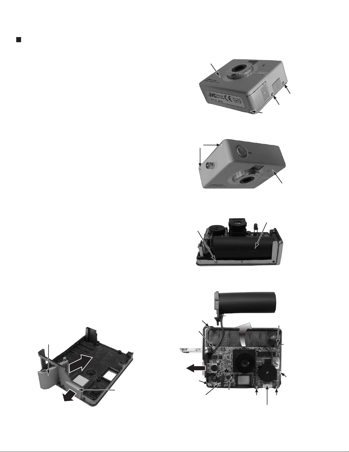
Disassembly method
Removing the battery cover and USB port cover
Remove the five screws A attaching the front case. (Fig.1,2)
1.
Remove the one screw B attaching the battery case. (Fig.3)
2.
Remove the five screws C attaching the main board. (Fig.4)
3.
Front case
Remove the two screws D attaching the shutter switch
4.
board. (Fig.4)
Open the rear case slightly in the direction that the arrow
5.
shows,and slide the main board to the bottom with raising
the main board a little.And the main board will be removed.
(Fig.4)
Remove the battery cover. (Fig.5)
6.
Remove the USB port cover. (Fig.5)
7.
A
A
A
Fig.1
A
Front case
Fig.2
Battery case
B
Battery cover
Fig.5
USB port cover
Rear case
C
C
Main board
Fig.4
Fig.3
C
C
C
DD
Shutter switch board
2
Page 3

Packing method and parts list
GC-A50 (J)/(C)/(K)/(H)/(E)
Packing method
*Upper box
*Cushion
(7) Name plate
: J33961-001
Main body
*Blister
These parts which was marked " * "(Upper
Note:
box/Cushion/Blister/Lower box/Sleeve) will
not be able to supply as our service parts.
(8) CD-ROM : J47109-001
(9) Quick start guide : J33964-001,002,003,004
(10) Caution sheet : J33965-001
(11) Warranty card (U.S.A) : BT-51007-6C
(12) Warranty card (Canada) : BT-52006-1C
(13) Service center list (Canada) : BT-20071B-C
(14) WindowsXP sheet : J47149-001,002
(4) Camera stand : J33962-001
*Sleeve
Top view
*Lower box
(2) USB Port cover
: J33957-001
(1) Battery cover
: J33977-001
(3) USB Cable : J33954-001
(5) Neck strap : J33959-001
(6) Hand strap : J33960-001
Parts list (General assembly and accessories)
Item No. Parts No. Parts name Q'ty Description
A
1
2
3
4
5
6
7
8
9
10
11
12
13
14
J33977-001
J33957-001
J33954-001
J33962-001
J33959-001
J33960-001
J33961-001
J47109-001
J33964-001,002,003,004
J33965-001
BT-51007-6C
BT-52006-1C
BT-20071B-C
J47149-001,002
Battery cover
USB Port cover
USB Cable
Camera stand
Neck strap
Hand strap
Name plate
CD-ROM
Quick start guide
Caution sheet
Warranty card (U.S.A)
Warranty card (Canada)
Service center list (Canada)
WindowsXP sheet
1
1
1
1
1
1
1
1
1
1
1
Only (J) version
1
Only (C) version
1
Only (C) version
1
3
Page 4

GC-A50 (J)/(C)/(K)/(H)/(E)
VICTOR COMPANY OF JAPAN, LIMITED
COMMUNICATION NETWORK BUSINESS UNIT
AV & MULTIMEDIA COMPANY 1644, Shimotsuruma, Yamato, Kanagawa 242-8514, Japan
No.70268
200208
 Loading...