

Page 1
DIGITAL GRAPHICS PROJECTOR
MANUEL D’INSTRUCTIONS : PROJECTEUR GRAPHIQUE NUMÉRIQUE
INSTRUCTIONS
G2000
For customer Use:
Enter below the Serial No. which is located
on the side panel of the cabinet. Retain this
information for future reference.
Pour l’utilisateur:
Inscrivez ci-dessous le No de série situé sur
le panneau latéral du coffret de l’appareil.
Conservez cette information à titre
d’information.
Model No.
No de modèle G2000
OPERATE
COMPUTER VIDEO
VOL.
ZOOM FOCUS
PAGE
BACK
PRESET
QUICK
ALIGN.AVMUTING
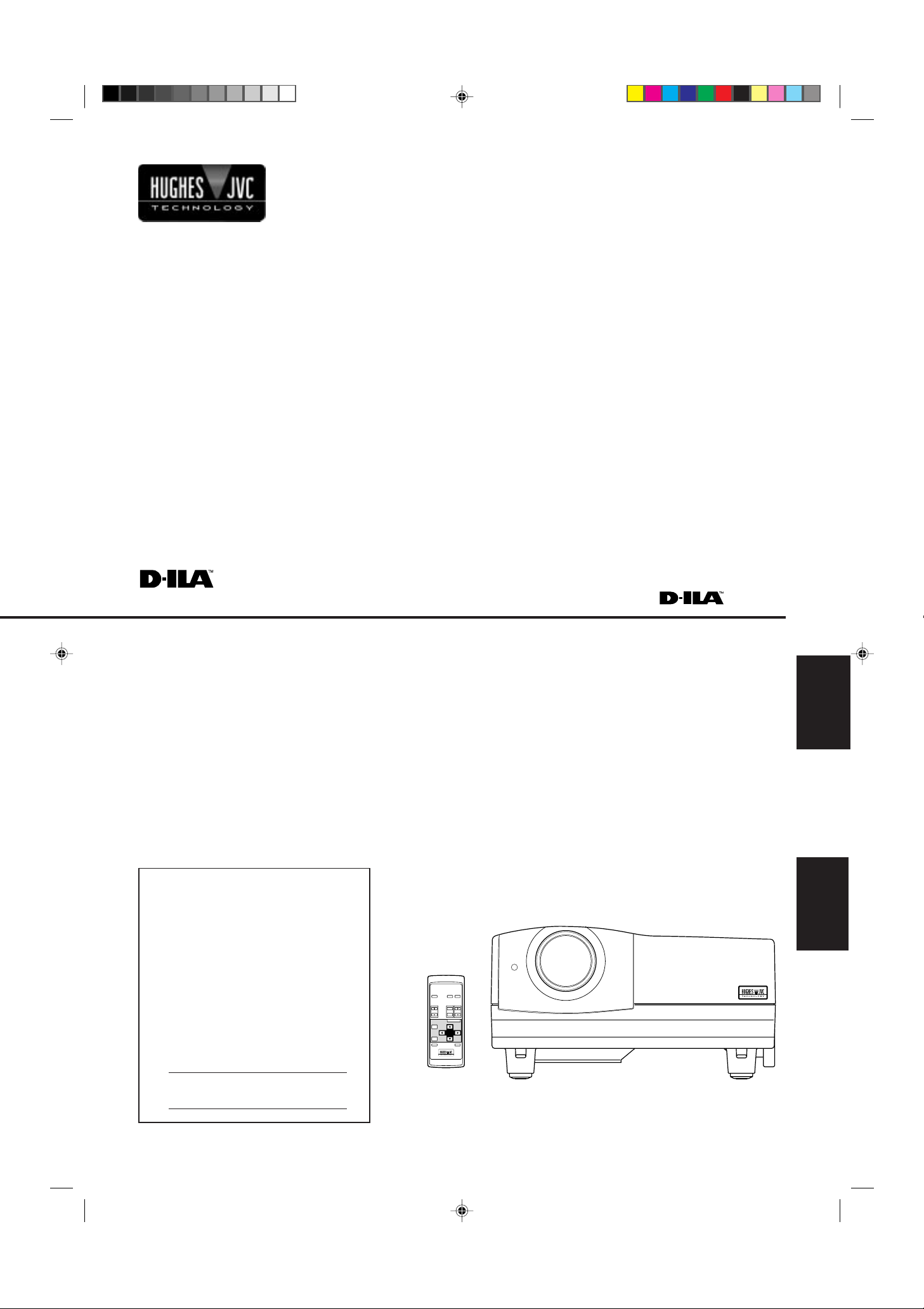
RM-M100 REMOTE CONTROL UNIT
T
W
MENU/ENTER
ENGLISH
FRANÇAIS
Serial No.
No de série
G2000 Cover(A4) 99.11.19, 10:42 PM3
Page 2

G2000 Cover(A4) 99.11.19, 10:42 PM4
Page 3
INSTRUCTIONS
DIGITAL
GRAPHICS PROJECTOR
G2000
ENGLISH
G2000 SubcoverEN 99.11.20, 3:27 AM1
1
Page 4
Thank you for purchasing this projector. Before using it, read and follow all instructions carefully to take full
advantage of the projector's capabilities.
SAFETY PRECAUTIONS
IMPORTANT INFORMATION
WARNING :
TO PREVENT FIRE OR SHOCK HAZARDS, DO NOT
EXPOSE THIS APPLIANCE TO RAIN OR MOISTURE.
CAUTION :
To reduce the risk of electric shock, do not remove cover.
Refer servicing to qualified service personnel.
This projector is equipped with a 3-blade grounding-type
plug to satisfy FCC rule. If you are unable to insert the
plug into the outlet, contact your electrician.
FCC INFORMATION (U.S.A. only)
CAUTION: Changes or modification not approved by
Hughes-JVC Technology Coporation could void the
user's authority to operate the equipment.
NOTE: This equipment has been tested and found to
comply with the limits for a Class A digital device,
pursuant to Part 15 of the FCC Rules. These limits
are designed to provide reasonable protection against
harmful interference when the equipment is operated
in a commercial environment. This equipment
generates, uses, and can radiate radio frequency
energy and, if not installed and used in accordance
with the instruction manual, may cause harmful
interference to radio communications. Operation of
this equipment in a residential area is likely to cause
harmful interference in which case the user will be
required to correct the interference at his own
expense.
About burning-in of the D-ILA device
Do not allow the same still picture to be projected for a long
time or an abnormally bright video picture to be projected.
Do not project video images with high-intensity or highcontrast on a screen. The video image could be burned in
to the D-ILA device.
Use special care when projecting video games or computer
program images. There is no problem with ordinary videocassette playback images.
IMPORTANT SAFEGUARDS
Electrical energy can perform many useful functions. This
unit has been engineered and manufactured to assure
your personal safety . But IMPROPER USE CAN RESUL T
IN POTENTIAL ELECTRICAL SHOCK OR FIRE
HAZARD. In order not to defeat the safeguards
incorporated into this product, observe the following basic
rules for its installation, use and service. Please read these
“Important Safeguards” carefully before use.
– All the safety and operating instructions should be read
before the product is operated.
– The safety and operating instructions should be retained
for future reference.
– All warnings on the product and in the operating
instructions should be adhered to.
– All operating instructions should be followed.
– Unplug this product from the wall outlet before cleaning.
Do not use liquid cleaners or aerosol cleaners. Use a
damp cloth for cleaning.
– Do not use attachments not recommended by the
product manufacturer as they may be hazardous.
– Do not use this product near water. Do not use
immediately after moving from a low temperature to high
temperature, as this causes condensation, which may
result in fire, electric shock, or other hazards.
– Do not place this product on an unstable cart, stand, or
table. The product may fall, causing serious injury to a
child or adult, and serious damage to the product. The
product should be mounted according to the
manufacturer’s instructions, and should use a mount
recommended by the manufacturer.
– When the product is used on a cart, care
should be taken to avoid quick stops,
excessive force, and uneven surfaces
which may cause the product and cart to
overturn, damaging equipment or causing
possible injury to the operator.
– Slots and openings in the cabinet are provided for
ventilation. These ensure reliable operation of the
product and protect it from overheating. These openings
must not be blocked or covered. (The openings should
never be blocked by placing the product on bed, sofa,
rug, or similar surface. It should not be placed in a built-
in installation such as a bookcase or rack unless proper
ventilation is provided and the manufacturer’s
instructions have been adhered to.)
2
G2000 p.02-04 Safety 99.11.20, 3:28 AM2
For proper ventilation, separate the product from other
equipment, which may prevent ventilation and keep
distance more than 60 cm (23-5/8”).
Page 5
SAFETY PRECAUTIONS (Cont.)
– This product should be operated only with the type of
power source indicated on the label. If you are not sure
of the type of power supply to your home, consult your
product dealer or local power company.
– This product is equipped with a three-wire plug. This
plug will fit only into a grounded power outlet. If you are
unable to insert the plug into the outlet, contact your
electrician to install the proper outlet. Do not defeat the
safety purpose of the grounded plug.
– Power-supply cords should be routed so that they are
not likely to be walked on or pinched by items placed
upon or against them. Pay particular attention to cords
at doors, plugs, receptacles, and the point where they
exit from the product.
– For added protection of this product during a lightning
storm, or when it is left unattended and unused for long
periods of time, unplug it from the wall outlet and
disconnect the cable system. This will prevent damage
to the product due to lightning and power line surges.
– Do not overload wall outlets, extension cords, or
convenience receptacles on other equipment as this can
result in a risk of fire or electric shock.
– Never push objects of any kind into this product through
openings as they may touch dangerous voltage points
or short out parts that could result in a fire or electric
shock. Never spill liquid of any kind on the product.
– Do not attempt to service this product yourself as opening
or removing covers may expose you to dangerous
voltages and other hazards. Refer all service to qualified
service personnel.
– Unplug this product from the wall outlet and refer service
to qualified service personnel under the following
conditions:
a) When the power supply cord or plug is damaged.
b) If liquid has been spilled, or objects have fallen on
the product.
c) If the product has been exposed to rain or water.
d) If the product does not operate normally by following
the operating instructions. Adjust only those controls
that are covered by the Operation Manual, as an
improper adjustment of controls may result in damage
and will often require extensive work by a qualified
technician to restore the product to normal operation.
e) If the product has been dropped or damaged in any
way.
f ) When the product exhibits a distinct change in
performance – this indicates a need for service.
– When replacement parts are required, be sure the service
technician has used replacement parts specified by the
manufacturer or with same characteristics as the original
part. Unauthorized substitutions may result in fire, electric
shock, or other hazards.
– Upon completion of any service or repairs to this product,
ask the service technician to perform safety checks to
determine that the product is in proper operating
condition.
– The product should be placed more than one foot away
from heat sources such as radiators, heat registers,
stoves, and other products (including amplifiers) that
produce heat.
– When connecting other products such as VCR’s, and
personal computers, you should turn off the power of
this product for protection against electric shock.
– Do not place combustibles behind the cooling fan. For
example, cloth, paper, matches, aerosol cans or gas
lighters that present special hazards when over heated.
– Do not look into the projection lens while the illumination
lamp is turned on. Exposure of your eyes to the strong
light can result in impaired eyesight.
– Do not look into the inside of this unit through vents
(ventilation holes), etc. Do not look at the illumination
lamp directly by opening the cabinet while the illumination
lamp is turned on. The illumination lamp also contains
ultraviolet rays and the light is so powerful that your
eyesight can be impaired.
– Xenon gas is enclosed with high pressure inside the light-
source lamp (lamp unit) of this projector. If you drop or
impart a shock to the lamp, or discard it as is, there is
the possibility of explosion, leading to personal injury.
Use special care when handling the lamp. For any
unclear points, consult your product dealer.
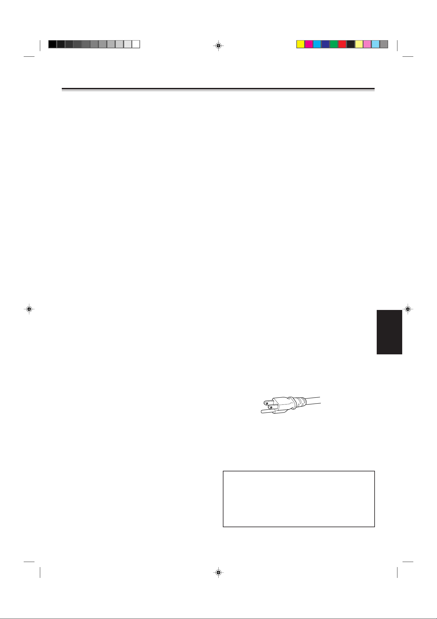
– Use only the accessory cord designed for this product to
prevent shock.
The power supply voltage rating of this product is AC
120 V, the power cord attached conforms to the
following power supply voltage. Use only the power
cord designated by our dealer to ensure Safety and
EMC.
When it is used by other power supply voltage, power
cable must be changed.
Consult your product dealer.
Power cord
Power supply voltage: AC 120 V
*DO NOT allow any unqualified person to
install the unit.
Be sure to ask your dealer to install the unit
(eg. attaching it to the ceilling) since special technical
knowledge and skills are required for installation.
If installation is performed by an unqualified person, it
may cause personal injury or electrical shock.
ENGLISH
G2000 p.02-04 Safety 99.11.20, 3:28 AM3
3
Page 6

Contents
SAFETY PRECAUTIONS........................... 2
Accessories ............................................... 5
Controls and Features .............................. 6
Front Side / Top Surface / Right Side.................... 6
Left-hand side .......................................................7
Bottom Surface .....................................................8
Control Panel ........................................................9
Connector Panel ................................................. 11
Remote Control Unit ........................................... 13
Installing Batteries............................................... 14
Installing the Projector ........................... 15
Precautions for installation..................................15
Projection Distance and Screen Size.................. 16
Relationship between Projection Distances and
Projection Screen Sizes................................. 17
Effective Range and Distance of the Remote
Control unit.....................................................18
Setting the Position Selecting Screw
for Ceiling Mounting .......................................18
Connecting to Various Devices ............. 19
Signals that Can Be Input to the Projector..........19
Connecting to Video Devices.............................. 20
Connecting to Hi-Vision Devices......................... 20
Connecting to Other Devices .............................. 21
Connecting to Devices which Control the
Projector.........................................................21
Connecting to Computer Devices .......................22
Connecting the Power Cord (Supplied) .............. 24
When Turning On the Devices Connected to the
Projector.........................................................25
Operating the Setting Menu ................... 32
Making Basic Settings.........................................32
Operating the Main Menu ....................... 33
Configuration of the Main Menu..........................33
Operating the Main Menu (Basic Operation of the
Main Menu) ....................................................35
Changing the Color System ................................ 36
Changing the Language Display.........................37
Adjusting the Pixel Clock .................................... 38
Adjusting the Screen Position ............................. 39
Adjusting Picture Quality.....................................40
Adjusting Sound Quality......................................43
Setting and Adjusting Other Functions
(OPTIONS) .................................................... 44
Changing (Setting) the Source............................47
Setting Up Channels ........................................... 49
Changing Channels ............................................ 54
Setting up (or Change) User Source................... 56
Setting up or Changing the Display Size ............59
Replacing the Fuse ................................. 60
Replacing the Light-Source Lamp......... 61
Resetting the Lamp Use Time.............................63
Cleaning and Replacing the Filter ......... 64
Troubleshooting ...................................... 65
Specifications.......................................... 67
Basic Operations..................................... 26
1. Turning on the Power...................................... 26
2. Select the video input to be projected.............27
3. Adjust the screen size..................................... 27
4. Adjust focus.....................................................28
5. Adjust sound volume....................................... 28
• For Operating Other Functions ......................... 29
*This manual is divided into two language sections:
English and French.
4
G2000 p.02-04 Safety 99.11.20, 3:28 AM4
Page 7
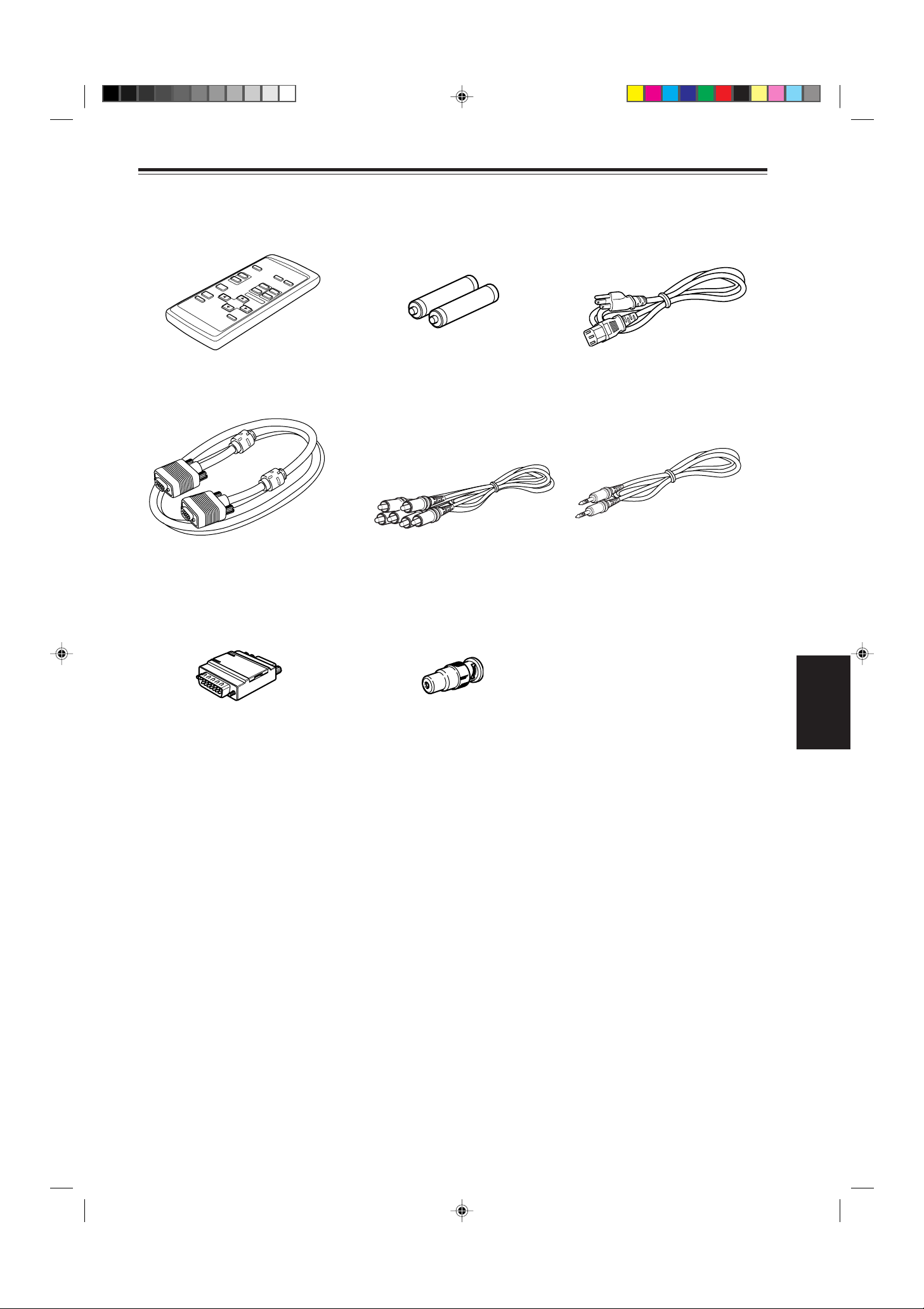
Accessories
The following accessories are included with this projector. Check for them; if any item is missing, please contact your
dealer.
Remote control unit (RM-M100U) AAA/R03-size dry cell battery (×2)
Personal computer connection cable
[approx. 2 m (6.56 ft)]
(D-sub, 3-row 15 pin)
Conversion adapter for Mac
(for Macintosh)
(for checking operation)
AV connection cable
[approx. 1.5 m (4.92 ft)]
BNC-RCA conversion plug
Power code
[approx. 2.5 m (8.2 ft)]
Audio cable
[approx. 3 m (9.84 ft)]
(3.5 mm dia. stereo mini plug)
ENGLISH
G2000 p.05-14 99.11.20, 3:28 AM5
5
Page 8
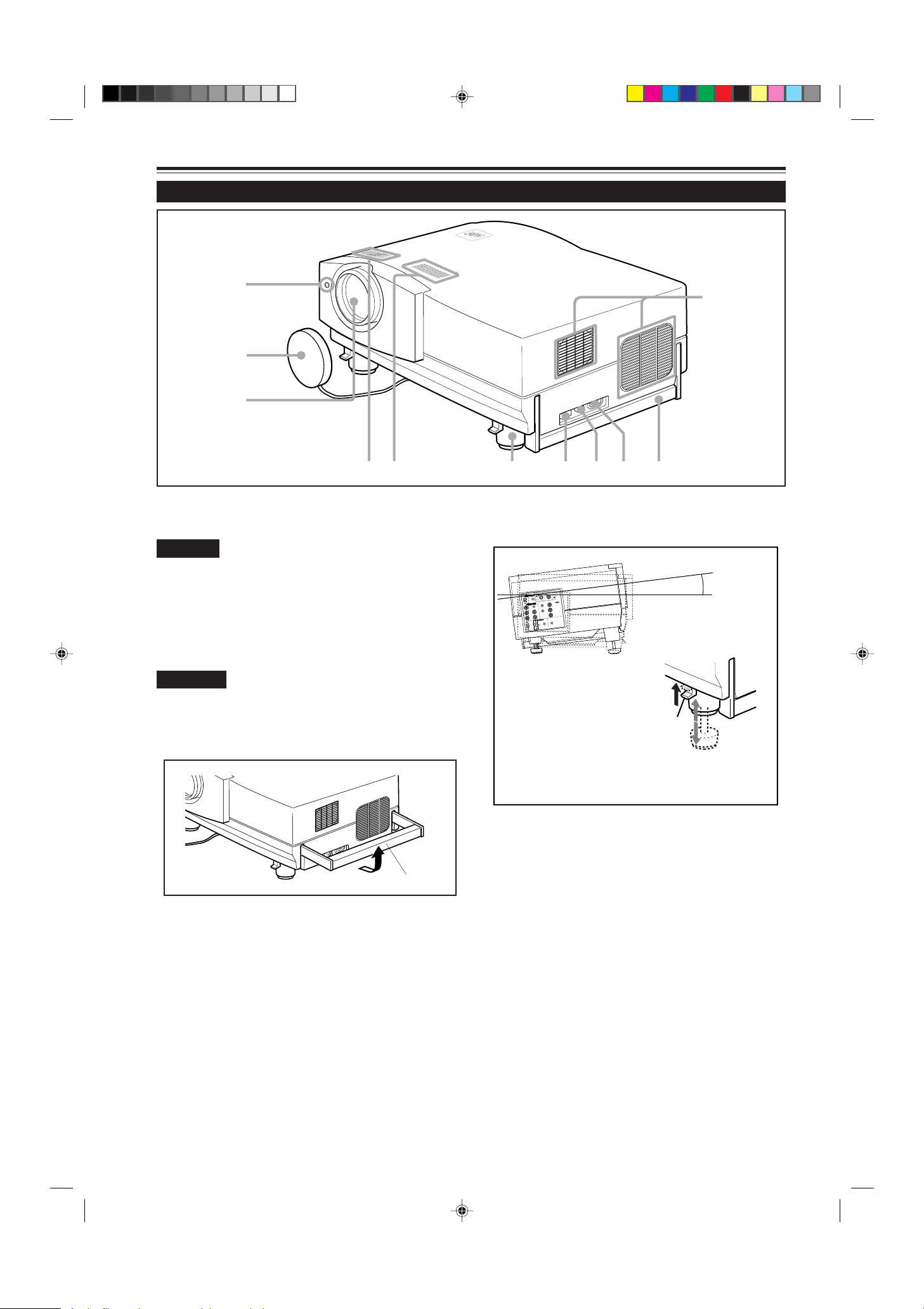
Controls and Features
lever
Y
PC
AUDIO
AUDIO
AUDIO
AUDIO OUT
REMOTE
Y
P
B
/B-Y
P
R
/R-Y
L
R
H/C
S
V
R
G
B
COMPUTER
OUT
RS-232C
Y/C VIDEO
•Extending the front
adjustable foot
While pushing the lever,
raise the projector, and
the adjustable foot extends
automatically.
To retract the foot, pushing
the lever , lower the projector slowly;
the projector is fixed at the position where you
release the lever.
+7°
Front Side / Top Surface / Right Side
q
p
9
8
7
Exhaust vents
1
Vents for cooling fans through which warm air comes out.
CAUTION
• Do not block the exhaust vents, or heat builds up inside,
possibly causing a fire. Also, do not touch the vents, or this
could cause a low-temperature burn.
Carrying handle
2
Raise this handle when carrying the projector.
1
4
56
Adjustable foot (for horizontal angle adjustment)
6
By extending the feet, the projector angle can be adjusted
up to +7°.
3
2
CAUTIONS
• When carrying the projector, do not give a shock to it. Be
careful to keep its balance.
• Do not carry it while the light source lamp is on or the cooling
fan is operating. This could cause personal injury.
How to use the carrying handle
AC IN (power input) terminal
3
This is the power input terminal where the supplied power
cord is connected. For details, refer to page 24.
Fuse holder
4
A fuse rated 15A/250V is installed. (Power source
protection)
T o replace the fuse, use a fuse with the same specifications.
MAIN POWER switch
5
This is the main power switch. When it is turned on, the
projector goes into stand-by state, and the STAND BY
indicator on the control panel comes on.
ON [ ❙ ]: The main power turns on.
OFF [
‡‡
‡]: The main power turns off.
‡‡
6
G2000 p.05-14 99.11.20, 3:28 AM6
Carrying handle
Built-in speaker (left)
7
Built-in speaker (right)
8
Lens
9
Projection lens, which is an electrically driven, approx. 1.5
x zoom lens. Before projection, remove the lens cap.
Lens cap
p
The cap has a string attached and the string is fixed to the
projector when shipped from the factory . It is recommended
that the cap be fitted on to prevent the lens becoming dirty
when the projector is not used.
Remote sensor
q
When operating with the remote control, aim it toward this
sensor. Y ou can also operate the remote control by pointing
it to a screen and allowing the remote sensor to receive
the reflected light.
Page 9
Controls and Features (cont.)
Left-hand side
w
STAND BY
LAMP
EMERGENCY
TEMP
VIDEO
COMPUTER
SETTING
QUICK
ALIGN
+
3
-
2
e
Control panel
w
For details, refer to “Control Panel” (page 9).
Connector panel
e
For details, refer to “Connector Panel” on page 11.
Adjustable foot (for horizontal angle adjustment)
r
It is set at the shortest position when shipped from the
factory. Turn the foot to make the projector level. Adjustment
can be made in the range of + 1.5° and – 1.5° from the
horizontal position.
r
+1.5°
–1.5°
•How to extend the adjustable foot on the rear
While raising the projector,,
turn the adjustable foot to
the right to extend it.
Extend
Shorten
ENGLISH
G2000 p.05-14 99.11.20, 3:28 AM7
7
Page 10
Controls and Features (cont.)
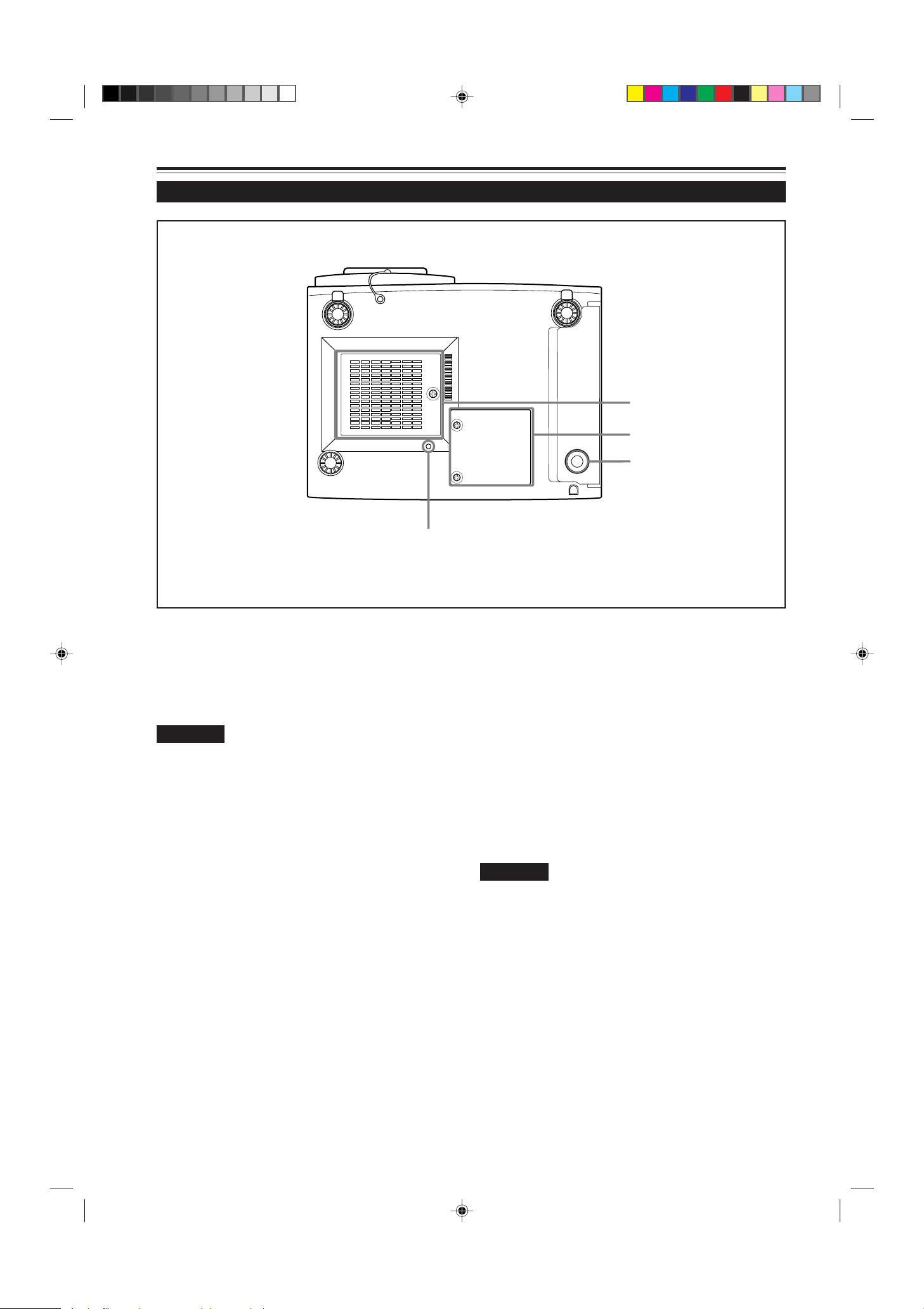
Bottom Surface
t
y
u
i
Air intake area (filter)
t
Air is taken in through this area to cool the light-source
lamp. If this area is blocked or if something that obstructs
taking in or exhausting air is placed around the projector,
heat may build up inside and could cause a fire. For details,
refer to “Precautions for Installation” on page 15.
CAUTIONS
• Be careful as paper, cloth or soft cushion could be drawn in
if placed nearby. Do not block the intake area, or heat may
build up and could cause a fire.
• Clean the filter periodically. For details, refer to “Cleaning
and Replacing the Filter” on page 64.
Deposition of dirt on the filter works to reduce the cooling
effect, causing heat to build up inside, which could cause a
fire or malfunction.
Opening for replacing the light-source lamp
y
For replacing the light-source lamp, refer to “Replacing the
Light-Source Lamp” on page 61.
Fixing foot
u
Position selecting screw for ceiling mounting
i
When using the projector in an upside-down, ceilingmounted position (inverted top-to-bottom and right-to-left),
the “position selecting screw for ceiling mounting” must be
turned to switch to ceiling mounting.
This will correct variance in color images (shading), which
otherwise would occur in ceiling mounting.
For more information, refer to “Setting the position
selecting screw for ceiling mounting” on page 18.
CAUTIONS
• To ceiling-mount and adjust the projector, special expertise
and technique are necessary. Be sure to ask your dealer or
a specialist to perform this work.
8
G2000 p.05-14 99.11.20, 3:28 AM8
Page 11
Controls and Features (cont.)
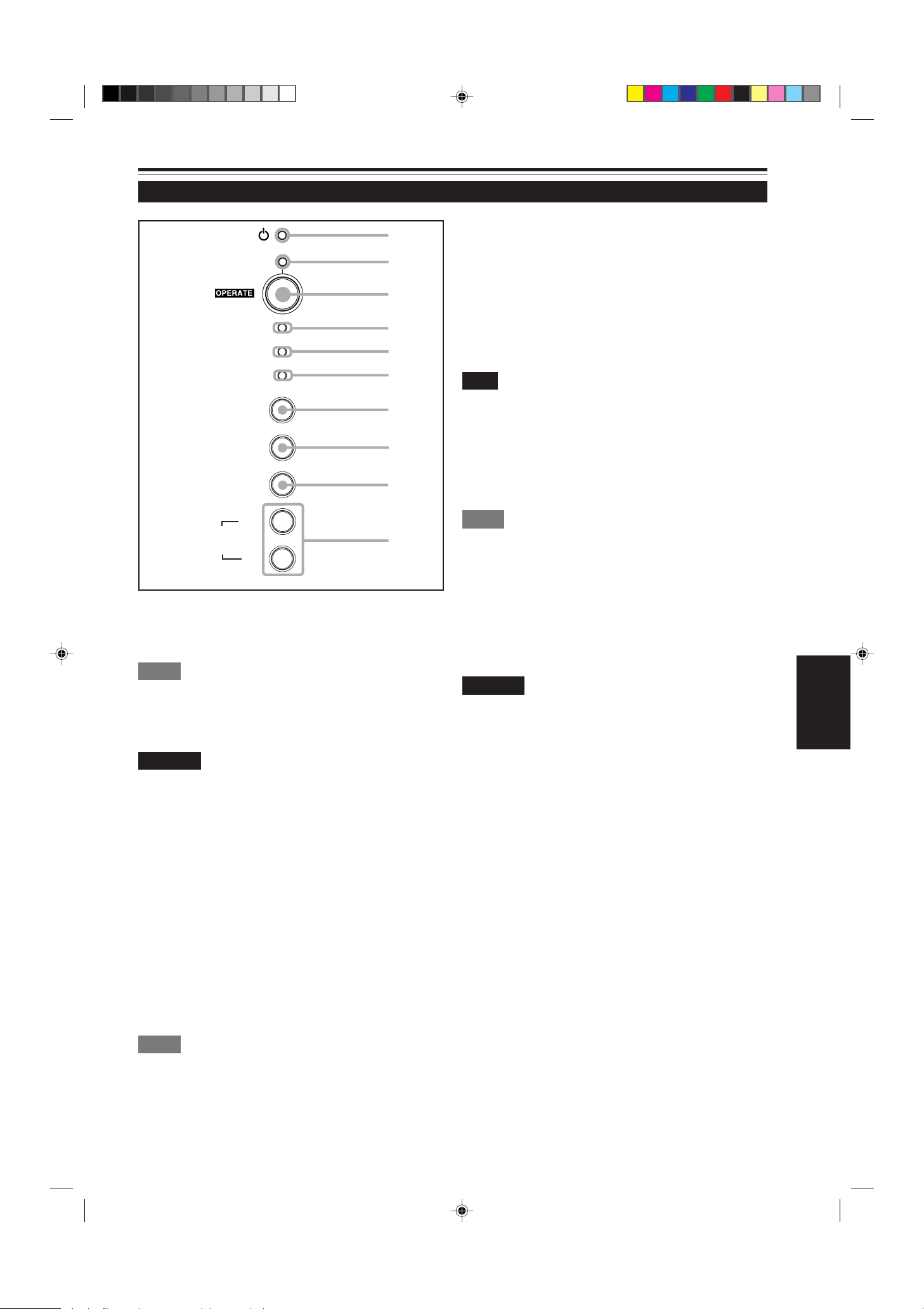
Control Panel
STAND BY
LAMP
TEMP
1
2
3
4
5
Lamp indicator
4
ON : After the light-source lamp has been used for
more than approx. 900 hours.
Blinking : Replace the lamp. Refer to “Replacing the Light-
Source Lamp” on page 61.
TEMP indicator
5
ON: The temperature inside the projector has abnormally
risen.
EMERGENCY
VIDEO
COMPUTER
SETTING
3
+
QUICK
ALIGN
STAND BY Indicator
1
ON : When in stand-by mode.
Blinking: When in cool-down mode.
Memo
About the cool-down mode:
This projector has a function to cool down the heated lamp for a fixed
period of time (approx. 120 seconds) after projection is finished. This
feature is referred to as the cool-down mode.
CAUTION
• The purpose of the cool-down mode is to prevent inner parts
from being deformed or broken by heat from the heated lamp
as well as to prolong the life of the lamp. Do not turn off the
main power switch while in the cool-down mode. Also, do
not place the projector on its side or stand it upright; this may
block the exhaust vents.
2
-
6
7
8
9
p
Note
• While the TEMP indicator is on (during abnormal temperature), the
power is automatically cut off, and an emergency mode is shown
(with the EMERGENCY indicator blinking).
EMERGENCY indicator
6
Blinking: Something abnormal has occurred with the
projector.
Memo
About the emergency mode:
The emergency mode is shown when the following anomalies have
occurred with the projector (the EMERGENCY indicator blinks). In
the emergency mode, projection is automatically interrupted and the
cooling fans operate for about 20 seconds.
• When the air filter is displaced.
• When the filter is clogged.
• When the light-source lamp has suddenly gone off.
• When the fans have stopped.
• When the temperature inside has risen abnormally high.
CAUTION
• When an emergency mode is shown:
After the cooling fans have stopped, turn off the main power
switch and unplug the power cord from the wall outlet.
Make sure the lamp-replacement cover and the air filter are
correctly installed. Then, plug in the power cord again and
operate the projector.
If it goes into an emergency mode again, after the cooling
fans have stopped, turn off the main power switch, unplug
the power cord, and call your dealer for repair.
ENGLISH
OPERATE indicator
2
ON: When the projector is in operation (projecting)
OPERA TE button
3
When the projector is in the stand-by mode, press this
button one second or more, and the main power switch is
turned on, causing the OPERATE indicator to light. Press
it one second or more again, and the projector goes into
the cool-down mode, then stand-by mode.
Memo
While in the cool-down mode:
If you press the OPERATE button, the projector is not tuned on.
G2000 p.05-14 99.11.20, 3:28 AM9
9
Page 12
Controls and Features (cont.)
Control Panel (Cont.)
STAND BY
LAMP
TEMP
EMERGENCY
VIDEO
1
2
3
4
5
6
7
QUICK ALIGN. button
p
While a menu screen is shown, use this button to adjust
the values for the item selected. When no menu is shown,
the quick alignment function works.
• When a menu is shown
+ 3 button: The value for the selected item increases.
– 2 button: The value for the selected item decreases.
• When no menu is shown
Press the +3 button and –2 button at the same time:
QUICK ALIGNMENT is displayed on the screen and the
quick alignment function works (TRACKING, PHASE, H.
POS. and V . POS. are automatically adjusted). When the
adjustment is finished, the display goes off automatically .
COMPUTER
SETTING
3
+
QUICK
ALIGN
VIDEO button
7
Use this button to select a device such as a video deck
connected to the A V IN terminal of the projector . Each time
you press the button, the device selected changes as
follows:
COMPUTER button
8
Use this button to select a device connected to the
COMPUTER -1 or -2 terminals. Each time you press the
button, the selection changes as follows:
Y/C
2
-
VIDEO
8
9
p
YPBPR
Memo
The quick alignment function :
• Works for computer input (COMPUTER- 1 and - 2 input terminals)
signals.
• Does not work for video input (AV IN input terminal) signals.
CAUTION
• Automatic adjustment with the quick alignment function
should be done on a bright still-picture screen. This function
may not work correctly on a dark screen or motion-picture
screen. If adjustment with this function is not satisfactory,
adjust TRACKING, PHASE, H. POS. and V. POS. manually
(see pages 32, 38 and 39).
COMP 1
SETTING button
9
Use this button to call up the setting menu. For details,
refer to “Making Basic Settings” on page 32.
COMP 2
10
G2000 p.05-14 99.11.20, 3:28 AM10
Page 13
Controls and Features (cont.)
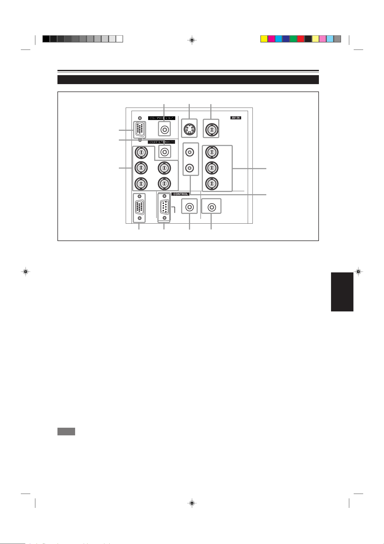
Connector Panel
w
AUDIO
q
PC
p
AUDIO
R
8
G
B
COMPUTER
OUT
7
9
Y/C (S video) input terminal (Mini DIN 4 pin)
1
Connect this terminal to the S video output terminal of a
video deck, etc.
VIDEO (composite video) input terminal (BNC)
2
Connect this terminal to the composite video output terminal
of a video deck, etc.
S
H/C
V
RS-232C
1
Y/C VIDEO
AUDIO
2
Y
L
R
Y
P
/B-Y
B
P
/R-Y
R
3
4
REMOTE
6
AUDIO OUT
5
AUDIO OUT (audio output) terminal (stereo mini jack)
5
Of input signals inputted to the projector, the audio signal
of the device being projected is output. Volume should be
adjusted using the VOL. (+/–) buttons on the remote control
or VOLUME on the setting menu. When a cable is
connected to this jack, no audio sound is produced from
the projector’s speakers.
Y, PB/B-Y, PR/R-Y input terminals (BNC)
3
These are input terminals for component (Y, B-Y, R-Y)
signals or DTV-format (Y, P
B, PR) signals.
Device with component output terminals can be
connected.
* For details about DTV-format signals (480i, 480p, 720p,
1080i) compatible with this unit, refer to page 69.
AUDIO L/R (Audio • left/right) input terminals (pin jacks)
4
Of devices connected to the video input terminals, such
as a video deck, etc., the audio output terminals of the
device to be projected is connected to these terminals.
The input audio signal is reproduced by the speakers of
the projector. The signal is also output from the AUDIO
OUT terminal of the projector.
* When the input signal is stereo signal, connection should
be made to both L and R.
* Signals from a monaural device should be connected to
only L. That way , the projector’s speakers and the AUDIO
OUT terminal produce the same sound from both L and R.
Memo
To select the proper audio input for video input:
The video input terminals (AV IN input terminals) can be switched
with the projector’s or remote control’s VIDEO button. However, since
this projector has only single audio input terminal, reconnect audio
input in accordance with the AV device to be used.
REMOTE terminal (mini jack)
6
Connect an infrared remote control extension unit, etc. to
this jack.
* For details, consult your dealer.
RS-232C terminal (D-sub 9 pin)
7
This is a RS-232C interface-specified terminal. This
projector can be controlled by a computer connected
externally.
* For details, consult your dealer.
COMPUTER OUT (computer output) terminal (D-sub
8
3-row 15 pin)
The computer input signal projected on the screen is output.
A display unit can be used by connecting it to this terminal.
ENGLISH
G2000 p.05-14 99.11.20, 3:28 AM11
11
Page 14
Controls and Features (cont.)
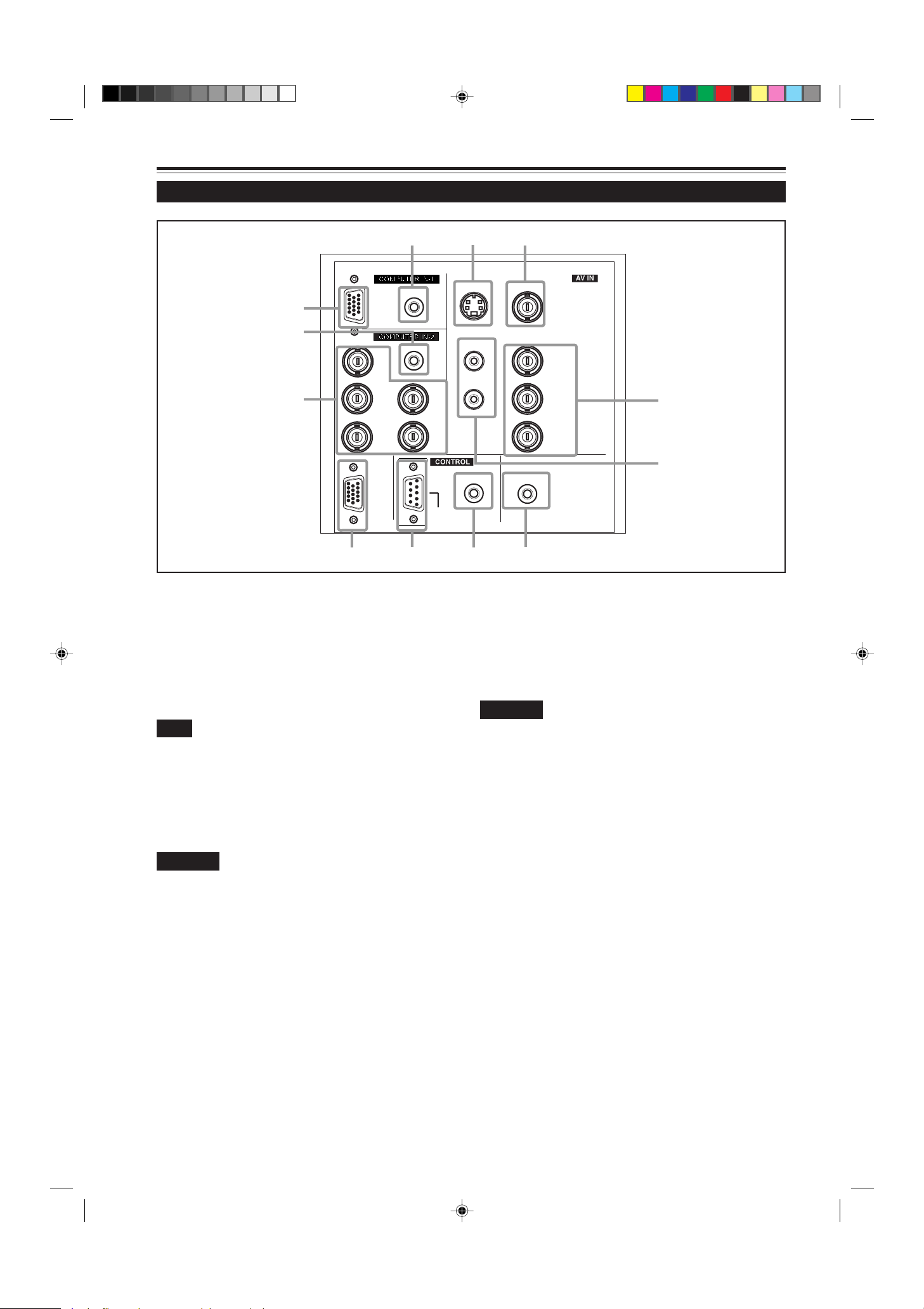
Connector Panel (Cont.)
w
AUDIO
q
PC
p
AUDIO
R
H/C
S
V
RS-232C
8
G
B
COMPUTER
OUT
7
9
COMPUTER IN (computer input) -2 terminal (BNC)
9
These are input terminals for analog RGB signals, vertical
sync (V) signals, and horizontal sync (H) signals /
composite signals(Cs). Devices which have analog RGB
signal output terminals can be connected.
* Input of external sync signals is automatically
detected.
Detection of H/V signals or Cs signals causes automatic
switch to external sync. The priority order is H/V > Cs.
Note
• DTV-format (480i, 480p, 720p, 1080i) signals can be input.
When the source is set to “AUTO”, signals of 480i and 1080i can
automatically be detected, but 480p and 720p signals can not be
detected.
To be able to input 480p or 720p signal, the source should be set
to a dedicated source mode “SDTV(480p)” or “HDTV(720p)”. For
setting the source, refer to “Changing (setting) the source” on
page 47.
CAUTION
• When computer-related signals are input, the uppermost
edge of the screen may appear bowing if the sync signal
input is composite sync (Cs) or G on sync signal. In that
case, use separate sync signals for vertical sync (V) and
horizontal sync (H).
AUDIO input terminal (stereo mini jack)
p
This is an audio input terminal for COMPUTER IN
(computer input) -2 terminal. Connect the audio output
signal of a device connected to COMPUTER IN (computer
input) -2 terminal.
* When input to COMPUTER -2 is selected, the audio signal
input is reproduced by the projector’s speakers. Also,
signals can be output from the AUDIO OUT (audio output)
terminal.
(However, if a cable is connected to AUDIO OUT (audio
output) terminal, audio sound does not come out from
the projector’s speakers.)
12
1
Y/C VIDEO
AUDIO
2
Y
L
R
Y
/B-Y
P
B
/R-Y
P
R
3
4
REMOTE
6
AUDIO OUT
5
COMPUTER IN (computer input) -1 terminal (D-sub 3-
q
row 15 pin)
This is an input terminal (PC) dedicated for computer
signals (RGB video signals and sync signals).
Connect the display output terminal of the computer to this
terminal. When a Macintosh computer is to be connected,
use the Conversion adapter for Mac supplied.
CAUTION
• When computer-related signals are input, the uppermost
edge of the screen may appear bowing if the sync signal
input is composite sync (Cs) or G on sync signal. In that
case, use separate sync signals for vertical sync (V) and
horizontal sync (H).
AUDIO (audio) input terminal (stereo mini jack)
w
This is an audio input terminal for COMPUTER IN
(computer input) -1 terminal. Connect the audio output
signal of a device connected to COMPUTER IN (computer
input) -1 terminal.
* When input to COMPUTER -1 is selected, the audio signal
input is reproduced by the projector’s speakers. Also,
signals can be output from the AUDIO OUT (audio output)
terminal.
(However, if a cable is connected to AUDIO OUT (audio
output) terminal, audio sound does not come out from
the projector’s speakers.)
G2000 p.05-14 99.11.20, 3:28 AM12
Page 15
Controls and Features (Cont.)
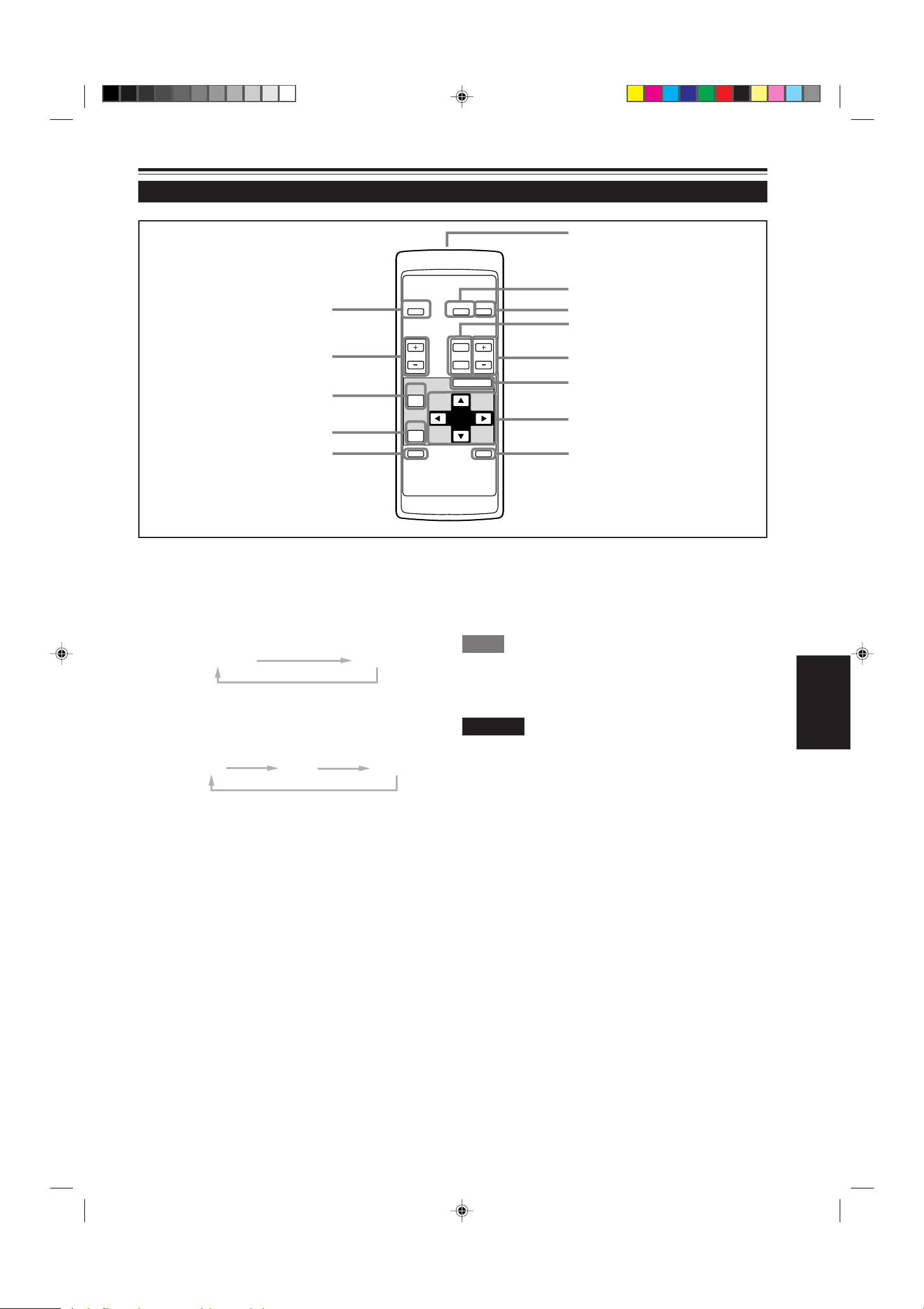
Remote Control Unit
e
w
q
OPERATE
VOL.
PAGE
BACK
COMPUTER VIDEO
T
ZOOM FOCUS
W
MENU/ENTER
1
2
3
4
5
6
p
9
Remote control’s signal transmitter
1
COMPUTER button
2
Use this button to select the devices connected to the
projector’s COMPUTER IN (computer input) -1 and -2 input
terminals. Each time you press the button, the selection
changes as follows:
COMP 1
VIDEO button
3
Use this button to select the devices such as a video
connected to the projector’s A V IN (A V input) terminal. Each
time you press the button, the selection changes as follows:
Y/C
ZOOM (T/W) button
4
VIDEO
Use these buttons to increase or decrease the screen size.
(The projector’s projection lens is an electrically driven
zoom lens of about 1.5 x.)
T:The screen size decreases.
W:The screen size increases.
COMP 2
YPBPR
PRESET
QUICK
ALIGN.
7
AV
MUTING
QUICK ALIGN. (Quick Alignment) button
9
Use this button to automatically adjust TRACKING,
PHASE, H. POS. and V. POS. of the projected video.
During the automatic adjustment, QUICK ALIGNMENT
appears on the screen, and disappears after it is finished.
Memo
Quick alignment function:
Does not work for video input (AV IN input terminal) signals.
Works only for computer-related (COMPUTER-1 and-2 input terminals)
signals.
CAUTION
• Automatic adjustment with the quick alignment function should be
done on a bright still-picture screen. This function may not work
correctly on a dark screen or motion-picture screen. If adjustment
with this function is not satisfactory, adjust TRACKING, PHASE, H.
POS. and V. POS. manually (see pages 32, 38 and 39).
PRESET button
p
While making adjustment on the main or setting menu,
use this button to reset the setting of the selected item to
the factory-set value. This button works only for numerical
settings and does not work for switching ON to OFF.
8
ENGLISH
FOCUS (+/–) button
5
Use these buttons to adjust the focus of the projected video.
+: The focus point becomes more distant.
–: The focus point becomes nearer.
MENU/ENTER button
6
Use this button to display the main menu. While the main
menu is displayed, pressing this button displays a details
setting (submenu) for items with details settings.
Cursor (5/∞/2/3) button
7
While the main menu is displayed, use these buttons to
select an item to adjust or make adjustment.
AV MUTING (On/Off) button
8
Use this button to turn off the video image and audio sound
temporarily . Pressing it again makes the video image and
audio sound to resume.
G2000 p.05-14 99.11.20, 3:28 AM13
PAGE BACK button
q
While a details setting is displayed, use this button to go
back to the previous page.
VOL. (Volume) (+/–) button
w
Use these buttons to adjust the sound volume:
+: Increase the volume level.
–: Decrease the volume level.
OPERATE button
e
To turn on the power, press this button for one second or
more.
* About 30 seconds after the power has turned on, video
image will appear on the screen.
13
Page 16
Controls and Features (cont.)
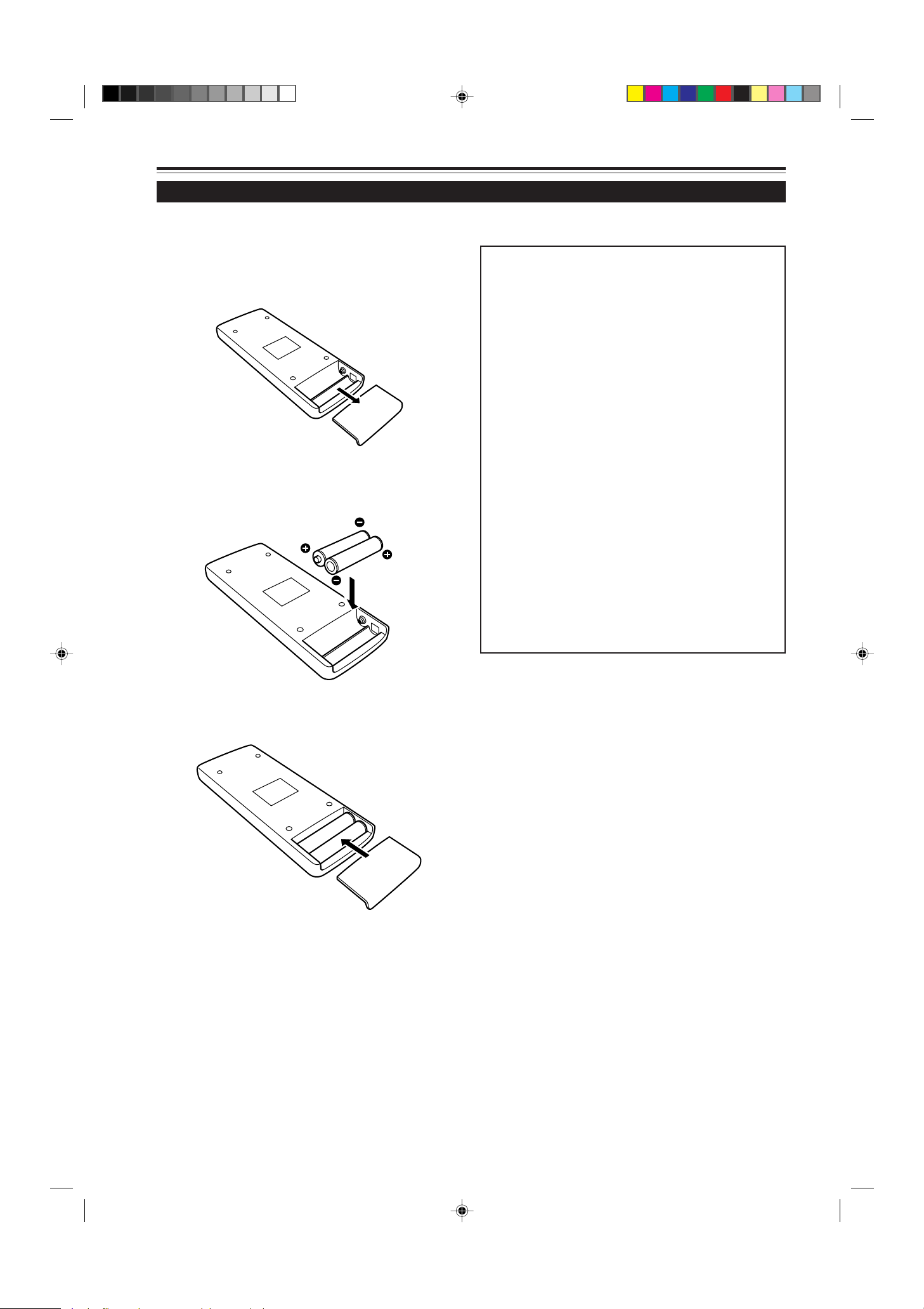
Installing Batteries
Install batteries in the remote control. If the remote control has started to work erratically, replace the batteries.
Open the back cover.
1
While pushing on the back cover, slide it in the direction
of the arrow.
Install the batteries.
2
Place the two batteries (AAA/R03-size) supplied in the
remote control as illustrated below.
Precautions for using batteries
If batteries are used incorrectly, they may crack or
leak liquid. This could cause a fire, burn, malfunction,
or staining or damaging the surrounding.
Beware of the following:
• Do not mix new and old batteries.
• Do not mix different types of batteries as they differ in
characteristics.
• Place batteries so they match the polarities indicated:
(+) to (+) and (–) to (–).
• Be sure to put the minus (–) end in first to avoid shortcircuiting.
• Use only designated batteries.
• Remove the batteries if not used for a prolonged period
of time.
• When the batteries are exhausted, replace them
immediately . Otherwise, liquid could leak, or malfunction
could occur due to leaked liquids. If the leaked liquid
contacts the skin, wipe it off with a cloth, otherwise the
skin could become rough.
• Do not put batteries into fire or try to recharge them.
• Batteries run for six months to one year in normal use.
But the batteries supplied are for confirming operation
and may not run that long. When the remote control starts
failing to work properly, replace the batteries with new
ones.
Close the back cover.
3
Slide the back cover in the direction of the arrow until a
click is heard.
14
G2000 p.05-14 99.11.20, 3:28 AM14
Page 17
Installing the Projector
Precautions for Installation
CAUTION
Do not install the projector in the following places :
• There is much water, humidity or dust.
• The projector may be subjected to oil smoke or cigarette smoke.
• On a soft surface such as a carpet or cushion.
• The projector may be subjected to direct sunlight.
• Temperature is high or humidity is low.
Allowable operation temperature range: + 5°C to + 35°C (41°F to 95°F)
Allowable relative humidity range: 20% to 80% (no condensation)
Allowable storage temperature range: –10°C to +60°C (14°F to 140°F)
■ When installing the projector, observe the followings:
• Do not use the projector placed on its side.
Avoid using the projector placed on its side. This could cause a malfunction.
• Use the projector within the installed angle.
Avoid using the projector inclined ±30° or more right-to-left or left-to-right. This could cause color variation or harm the lamp
life.
• Do not block the exhaust vents.
Do not use a cover which encloses the projector air-tight or blocks the exhaust vents. Allow sufficient space around the
projector. When the projector is enclosed in a space of the following dimensions, use an air conditioner so the temperature
inside becomes equal to the outside temperature.
Allowable minimum space required
20cm (7 - 7/8”) 60cm (23 - 5/8”)
30cm (11 - 13/16”)
ENGLISH
30cm (11 - 13/16”)
G2000 p.15-23 99.11.20, 3:28 AM15
20cm (7 - 7/8”)
15
Page 18
Installing the Projector (Cont.)
Projection Distance and Screen Size
■ The projector ’s projection lens is a zoom lens of about 1.5 x. The screen size at the maximum enlargement is 1.5
times that of the minimum size.
■ The projection distance that can be focused is 2.5 to 20 m. Install the projector within this range.
Screen
■ Change of projection screen
according to aspect ratio
Screen with 4 : 3 aspect ratio
Screen with 16 : 9 aspect ratio
90°
Install the projector so the lower
edge of the projection screen is
at the same height as the lens’
center line.
Projection
distance
8.2 ft 42” 63” 39” 57”
(2.5 m) (approx. 107 cm) (approx. 160 cm) (approx. 100 cm) (approx. 144 cm)
16.4 ft 86” 128” 79” 117”
(5 m) (approx. 219 cm) (approx. 325 cm) (approx. 201 cm) (approx. 297 cm)
32.8 ft 172” 259” 158” 237”
(10 m) (approx. 437 cm) (approx. 657 cm) (approx. 402 cm) (approx. 601 cm)
65.6 ft 345” 521” 317” 478”
(20 m) (approx. 877 cm) (approx. 1,323 cm) (approx. 806 cm) (approx. 1,214 cm)
Minimum projection screen Maximum projection screen Minimum projection screen Maximum projection screen
When screen aspect ratio is 4 : 3 When screen aspect ratio is 16 : 9
90° 90°
Center line of the lens
Projection screen size (diagonal length)
*Also, refer to the table of “Relationship Between Projection Distances and Projection Screen Sizes” on page 17 as a reference.
CAUTIONS and NOTES
• Install the screen so the lower edge of the projected picture aligns with the extended center line of the projector ’s lens.
That way , the lower edge of the picture projected on a 4 : 3 aspect ratio screen aligns with the extended center line of the
lens. Also, the screen must be at right angles with the extended center line of the lens (so that projection occurs at right
angles with the screen).
• When installing the screen, use a 4 : 3 aspect ratio picture.
(A 16 : 9 aspect ratio picture is projected based on the width of the range in which a 4 : 3 aspect ratio picture is projected.)
• The diagonal length of a 16 : 9 aspect ratio picture is about 91.8% that of a 4 : 3 aspect ratio picture. This value is a guide
and should be used as a reference.
• When projecting at the maximum projection distance (20 m/65.6 ft), we recommend that the projector be used with the
zoom on the Tele (T).
• If sunlight or lamp light strikes the projection screen directly, the picture becomes whitish and dim. Be sure to use a
curtain, etc. to shield the light.
• Trapezoidal distortion may not be corrected.
Adjust the projector within the range of angle adjustment (up/down adjustment angle: +7°; horizontal adjustment angle:
±1.5°) so that it is set up level.
• The numeric values listed in the table of Relationship between Projection Distances and Screen Sizes on page 17 are
provided only as a guide or reference. The projection sizes may vary within manufacturing tolerances of the projection
lens.
• When hanging the projector from the ceiling, use a dedicated hanging fixture.
16
G2000 p.15-23 99.11.20, 3:28 AM16
Page 19
Installing the Projector (Cont.)
Relationship between Projection Distances and Projection Screen Sizes
■ For 4 : 3 aspect ratio screens
Projection
distance
8.2 ft (2.5 m) 42” (approx. 107 cm) 63” (approx. 160 cm)
9.84 ft (3.0 m) 51” (approx. 130 cm) 76” (approx. 193 cm)
13.12 ft (4.0 m) 68” (approx. 173 cm) 102” (approx. 259 cm)
16.4 ft (5.0 m) 86” (approx. 219 cm) 128” (approx. 325 cm)
19.68 ft (6.0 m) 103” (approx. 262 cm) 154” (approx. 391 cm)
22.96 ft (7.0 m) 120” (approx. 305 cm) 180” (approx. 457 cm)
26.24 ft (8.0 m) 138” (approx. 351 cm) 207” (approx. 525 cm)
29.52 ft (9.0 m) 155” (approx. 394 cm) 233” (approx. 591 cm)
32.8 ft (10.0 m) 172” (approx. 437 cm) 259” (approx. 657 cm)
36.08 ft (11.0 m) 190” (approx. 483 cm) 285” (approx. 723 cm)
39.36 ft (12.0 m) 207” (approx. 526 cm) 310” (approx. 787 cm)
42.64 ft (13.0 m) 224” (approx. 569 cm) 338” (approx. 858 cm)
45.92 ft (14.0 m) 242” (approx. 615 cm) 364” (approx. 924 cm)
49.2 ft (15.0 m) 260” (approx. 661 cm) 390” (approx. 990 cm)
52.48 ft (16.0 m) 276” (approx. 702 cm) 416” (approx. 1,056 cm)
55.76 ft (17.0 m) 294” (approx. 747 cm) 443” (approx. 1,125 cm)
59.04 ft (18.0 m) 311” (approx. 790 cm) 469” (approx. 1,191 cm)
62.32 ft (19.0 m) 328” (approx. 834 cm) 495” (approx. 1,257 cm)
65.6 ft (20.0 m) 345” (approx. 877 cm) 521” (approx. 1,323 cm)
Minimum projection screen size (Tele end) Maximum projection screen size (Wide end)
Projection screen size (diagonal length)
■ For 16 : 9 aspect ratio screens
Projection
distance
8.2 ft (2.5 m) 39” (approx. 100 cm) 57” (approx. 144 cm)
9.84 ft (3.0 m) 47” (approx. 120 cm) 69” (approx. 175 cm)
13.12 ft (4.0 m) 63” (approx. 161 cm) 93” (approx. 236 cm)
16.4 ft (5.0 m) 79” (approx. 201 cm) 117” (approx. 297 cm)
19.68 ft (6.0 m) 95” (approx. 242 cm) 140” (approx. 355 cm)
22.96 ft (7.0 m) 110” (approx. 280 cm) 165” (approx. 419 cm)
26.24 ft (8.0 m) 126” (approx. 321 cm) 189” (approx. 480 cm)
29.52 ft (9.0 m) 142” (approx. 361 cm) 213” (approx. 541 cm)
32.8 ft (10.0 m) 158” (approx. 402 cm) 237” (approx. 601 cm)
36.08 ft (11.0 m) 174” (approx. 442 cm) 260” (approx. 660 cm)
39.36 ft (12.0 m) 190” (approx. 483 cm) 286” (approx. 726 cm)
42.64 ft (13.0 m) 206” (approx. 524 cm) 310” (approx. 787 cm)
45.92 ft (14.0 m) 222” (approx. 564 cm) 334” (approx. 848 cm)
49.2 ft (15.0 m) 238” (approx. 605 cm) 358” (approx. 909 cm)
52.48 ft (16.0 m) 254” (approx. 646 cm) 382” (approx. 970 cm)
55.76 ft (17.0 m) 270” (approx. 686 cm) 406” (approx. 1,031 cm)
59.04 ft (18.0 m) 285” (approx. 724 cm) 430” (approx. 1,092 cm)
62.32 ft (19.0 m) 301” (approx. 765 cm) 454” (approx. 1,153 cm)
65.6 ft (20.0 m) 317” (approx. 806 cm) 478” (approx. 1,214 cm)
Minimum projection screen size (Tele end) Maximum projection screen size (Wide end)
Projection screen size (diagonal length)
ENGLISH
G2000 p.15-23 99.11.20, 3:28 AM17
17
Page 20
Installing the Projector (Cont.)
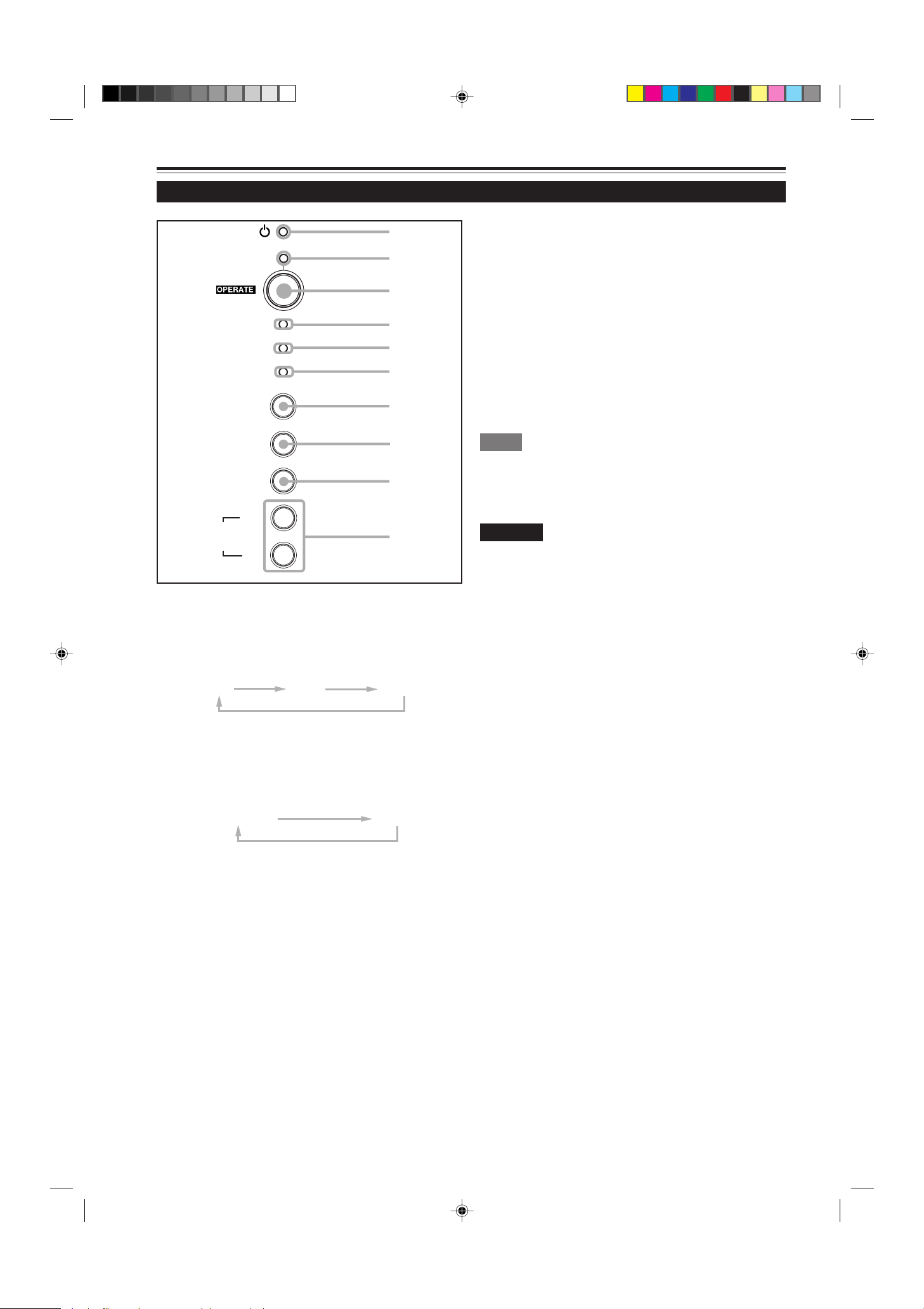
Effective Range and Distance of the Remote Control Unit
The operable distance of the remote control unit is about 10 m (32.8 ft) for direct reception. The remote control can be used by
having it reflected on the screen, etc. When you use the remote control by reflecting it at the screen, the total distance of A + B
should be about 10 m (32.8 ft) or less. The operable angles of the remote control unit is 50° right to left, and 15° up and down.
The effective range and distance of the remote control unit
• Use the projector with A+B about 10 m (32.8 ft) or less.
50˚
Projector
(G2000)
50˚
A
Screen
30˚
B
Remote control unit
Note
• Depending on the type of the screen used, the effective distance of the remote control may be reduced.
Setting the position selecting screw for Ceiling Mounting
When using the projector in an upside-down, ceiling-mounted position (inverted top-to-bottom and right-to-left), the “position
selecting screw for ceiling mounting” must be turned to switch to ceiling mounting.
This will correct variance in color images (shading), which otherwise would occur in ceiling mounting.
To revert to normal desltop setting, turn the “position selecting screw for ceiling mounting” back to the initial position (factoryshipped).
[When using the projector in an upside-down, ceiling mounting position (inverted top-to-bottom and right-to-left)]
■ Turn the “position selecting screw for ceiling mounting” counterclockwise fully (until it is turning idly).
[To again use the projector in a normal desktop setting]
■ Turn the “position selecting screw for ceiling mounting” clockwise fully (until it tightens firmly).
For normal desktop mounting:
Turn clockwise.
For upside-down, ceiling-mounting:
Turn counterclockwise.
CAUTIONS
• To ceiling-mount and adjust the projector, special expertise and
technique are necessary. Be sure to ask your dealer or a specialist to
perform this work.
• To turn the “position selecting screw for ceiling mounting”, use a Phillips
Position selecting screw for ceiling mounting
18
screwdriver with a 30-mm or longer shank.
The screw is located in the hole shown in the illustration.
G2000 p.15-23 99.11.20, 3:28 AM18
Page 21

Connecting to Various Devices
* Before connection, be sure to turn off the projector and connected devices.
* Read the manual which comes with each device thoroughly.
Signals that Can Be Input to the Projector
The following signals can be input to the projector:
■ Video signals
(1) Response to color systems
Input terminal
VIDEO ‡‡‡‡
Y/C ‡‡*
Y, PB/B-Y, PR/R-Y ‡*
G, B, R, H/CS, V ‡*
*
: Responds if Y/C output is available.
1
*
: Signifies that component signals (“Y, PB, PR ” / “ Y, B-Y , R-Y” / “G, B, R, H/CS, V”) conform to the signal timing (synchroniza-
2
Color system
tion and video period) of each color system. The color systems are used for convenience only.
(2) Response to double density (*1), high-vision signals
Input terminal NTSC*
Y, PB/B-Y, PR/R-Y ‡‡‡
G, B, R, H/CS, V ‡‡‡
*1 : Signals whose density of scanning lines/field is twice as high.
*
: Responds to signals whose horizontal scanning frequency is 31.5 kHz. NTSC can be made twice as dense by a line doubler
2
(separately available: recommended article). Also, possible to respond to fully-specified, decoded 525P progressive signals.
*
: Responds to signals whose horizontal scanning frequency is 33.5 kHz. PAL can be made twice as dense by a line doubler
3
(separately available: recommended article).
Note
• DTV-format signals (480i, 480p, 720p, 1080i) can be input into this unit (Y, PB/B-Y, PR/R-Y input terminals). For details about DTV-format
signals (480i, 480p, 720p, 1080i) compatible with this unit, refer to page 69.
NTSC NTSC4.43 PAL SECAM
1
2
2
2
‡*
‡*
2
2
PAL*
3
‡ - - - - ‡*
‡*
2
2
High-vision signal
‡*
‡*
2
2
■ Computer signals
• Signals with the following resolutions can be input to the input terminal of COMPUTER IN-1 (PC) or COMPUTER IN-2 (G,
B, R, H/Cs, V). (The following signals are preset.)
Screen resolution (standard name) Horizontal frequency Vertical frequency Scanning method
640 × 400 (PC-9801) 24.8kHz 56.4Hz Non-interlace
640 × 350 (VGA1) 31.5kHz 70.1Hz Non-interlace
640 × 480 (VGA3) 31.5kHz 59.9Hz Non-interlace
640 × 480 (Macintosh 13”) 35.0kHz 66.7Hz Non-interlace
640 × 480 (VGA VESA) 37.5kHz 75.0Hz Non-interlace
800 × 600 (SVGA1) 37.9kHz 60.3Hz Non-interlace
800 × 600 (SVGA2) 48.1kHz 72.2Hz Non-interlace
832 × 624 (Macintosh16”) 49.7kHz 74.6Hz Non-interlace
1024 × 768 (XGA1) 48.4kHz 60.0Hz Non-interlace
1024 × 768 (XGA2) 56.5kHz 70.1Hz Non-interlace
1024 × 768 (Macintosh 19”) 60.2kHz 74.9Hz Non-interlace
1152 × 870 (Macintosh 21”) 68.7kHz 75.0Hz Non-interlace
1280 × 1024 (SXGA1) 64.0kHz 60.0Hz Non-interlace
1280 × 1024 (SXGA2) 70.8kHz 67.0Hz Non-interlace
1360 × 1024 (SXGA3: Mac Board) 80.0kHz 75.1Hz Non-interlace
Notes
• Interlace signals are not handled.
• Some signals other than listed above can be displayed. But they require adjustment. Even some of the signals listed above may require
adjustment depending on the video board used.
• When a signal other than listed above is input, the screen could be partially erased or an unneeded fold-over screen could appear.
• Even signals in the frequency range that can be input may not be displayed normally depending on the type of the signal.
• Composite sync.(Cs) and G on sync. signals can not handled depending on the devices connected.
19
ENGLISH
G2000 p.15-23 99.11.20, 3:28 AM19
Page 22
Connecting to Various Devices (Cont.)
Connecting to Video Devices
Before connection, be sure to turn off both the projector and video device.
• Read the manual which comes with each video device thoroughly.
• Use the supplied AV connection cable. An AV connection cable with an S video terminal is not supplied.
S video cable
To Y/C
(separately available)
BNC-RCA conversion plug (accessory)
To VIDEO
T o AUDIO (L)
T o AUDIO (R)
AV connection
cable
(accessory)
V
Y/C VIDEO
AUDIO
L
R
REMOTE
AUDIO OUT
Y
Y
P
/B-Y
B
P
/R-Y
R
To select the proper audio input for video input
The video input terminal (AV IN input terminal) can
be switched with the VIDEO button. However, since
this projector has only a single audio input terminal,
reconnect audio input in accordance with the AV
device to be used.
Connecting to Hi-Vision Devices
Video devices
• VCR (Video Cassette recorder)
• Laser video disc player
• Camcorder
Memo
• When connecting a video device, use a TBC along with it, or one
which has a built-in TBC.
• Use of an extension cable to connect a video device and the
projector could cause video degradation.
• When a signal with much jitter is reproduced on a VCR or specialeffect playback is performed, the upper part of the picture or the
picture itself may be erased or distorted.
Before connection, be sure to turn off both the projector and Hi-Vision devices.
• Read the manual which comes with each Hi-Vision device thoroughly.
• Use separately available BNC cables and audio cables to connect Hi-Vision devices.
T o AUDIO (R)
T o AUDIO (L)
Audio cable
(separately available)
To VIDEO
To Y
To PB/B-Y
To PR/R-Y
BNC cable (separately available)
V
RS-232C
Y/C VIDEO
AUDIO
L
R
REMOTE
AUDIO OUT
Y
Y
P
/B-Y
B
P
/R-Y
R
To select the proper audio input for video input
The video input terminal (AV IN input terminal) can
be switched with the VIDEO button. However, since
this projector has only a single audio input terminal,
reconnect audio input in accordance with the AV
device to be used.
Hi-Vision devices
• W-VHS VCR
• Text/video camera
• Hi-Vision video camera
Memo
• Other devices with component signal output terminals (DVD player
(NTSC), etc.) can be connected. (*DVD: Digital Video Disc)
• DTV-format signals (480i, 480p,720p,1080i) can be input. For DTV format signals that can be handled, refer to page 69.
20
G2000 p.15-23 99.11.20, 3:28 AM20
Page 23
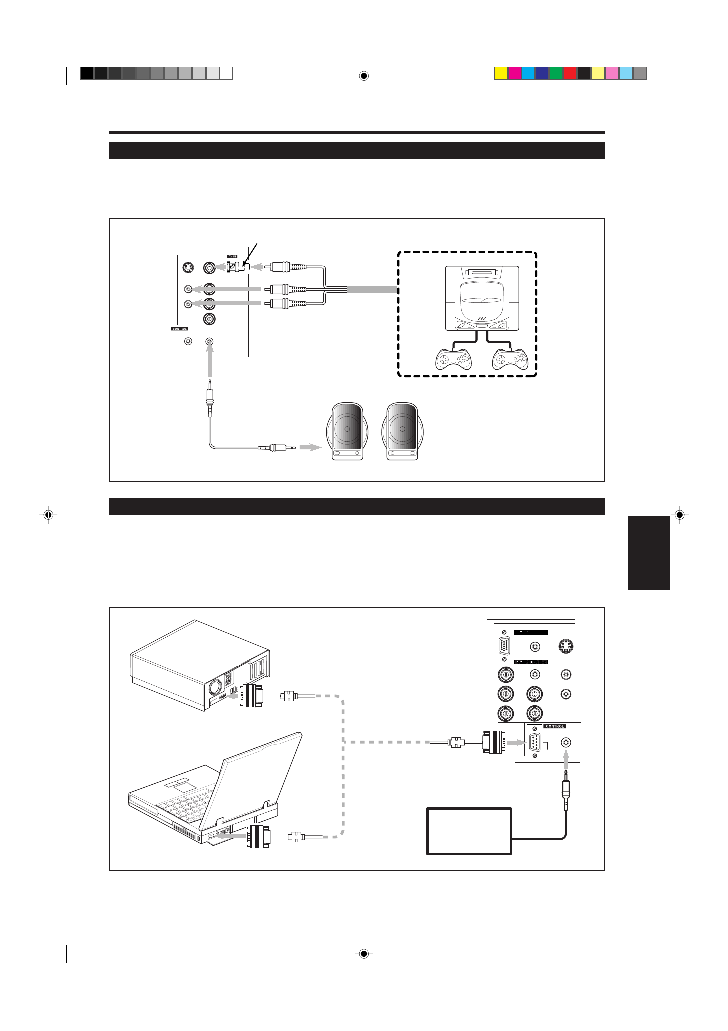
Connecting to Various Devices (Cont.)
Connecting to Other Devices
Before connection, be sure to turn off both the projector and other devices to be connected.
• Read the manual thoroughly which comes with the device to be connected.
• Speakers with a built-in amplifier and game devices can be connected. Use the AV connection cable and audio cable supplied,
or the cable supplied with a game device.
V
RS-232C
Y/C VIDEO
AUDIO
L
R
REMOTE
BNC-RCA conversion plug (supplied)
To VIDEO
T o AUDIO (L)
Y
Y
/B-Y
P
B
T o AUDIO (R)
Cable supplied with the game
device, or supplied AV connection
AUDIO OUT
/R-Y
P
R
cable
T o AUDIO OUT
• Speakers with a built-in amplifier
• Game device, etc.
Audio cable (supplied)
(or stereo mini-plug)
Connecting to Devices which Control the Projector
Before connection, be sure to turn off both the projector and devices to be connected.
• Read the manual thoroughly which comes with each device to be connected.
• By connecting a computer to the RS-232C terminal, you can control the projector. Also, you can make an infrared remote
sensor extension unit and connect it to the REMOTE terminal of the projector.
* Obtain connection cables as required.
* For details, consult a authorized your dealer or service center.
• Desktop type
S
H/C
V
RS-232C
Y/C
AUDIO
L
R
REMOTE
• Note type
To RS-232C connector
To RS-232C connector
RS-232C reverse connection
cable (separately available)
To RS-232C connector
Infrared remote
sensor extension unit
(Needs to be made)
AUDIO
PC
AUDIO
R
G
B
COMPUTER
OUT
To REMOTE terminal
ENGLISH
G2000 p.15-23 99.11.20, 3:28 AM21
21
Page 24

Connecting to Various Devices (Cont.)
Connecting to Computer Devices
Before connection, be sure to turn off both the projector and computer devices.
• Read the manual which comes with each device thoroughly.
■ Connection to an IBM PC or IBM-compatible computer
• Use the supplied computer connection cable. Also, prepare cables required for connecting the devices connected.
• Desktop type
Computer cable (supplied)
To monitor connector
• Note type
* There are some note types which do not allow the computer ’s
LCD to work if an external display is connected. With such a note
type, the LCD display and external display output need to be
switched.
When connecting an audio output terminal such as a computer sound
source to the projector, connect to the AUDIO terminal using the supplied
audio cable.
To COMPUTER IN-1
S
H/C
V
RS-232C
Y/C
AUDIO
L
R
REMOTE
To H/Cs
To R
To G
To B
To COMPUTER IN-2
AUDIO
PC
AUDIO
R
G
B
COMPUTER
OUT
To COMPUTER OUT
To V
• Desktop type
• RGB output devices
To monitor connector
Laser video disc player, etc.
Separate cable
(separately available)
To R
To G
To B
To H/Cs
To V
Cable supplied with the
display (or separately
available)(D-sub 3-row
15-pin)
POWER
Display monitor
* When a monitor is connected to the
COMPUTER OUT terminal, you can view
the video from the computer on the
monitor.
22
G2000 p.15-23 99.11.20, 3:28 AM22
Page 25

Connecting to Various Devices (Cont.)
Connecting to Computer Devices (Cont.)
Before connection, be sure to turn off both the projector and computer devices.
• Read the manual which comes with each device thoroughly.
■ Connection to Macintosh
• Use the supplied Personal computer connection cable and the supplied conversion adapter for Mac.
• When connecting an audio output terminal such as a computer sound
source to the projector, connect to the AUDIO terminal using the
supplied audio cable.
• Desktop type
• Other connections are the same as in the connection example for
IBM PC or IBM compatible PCs.
To monitor connector
Conversion adapter for Mac
(supplied)
Personal computer connection cable
(supplied)
To COMPUTER IN-1
PC
R
G
B
COMPUTER
OUT
AUDIO
AUDIO
H/C
V
RS-232C
Y/C
AUDIO
L
R
S
REMOTE
ENGLISH
G2000 p.15-23 99.11.20, 3:28 AM23
23
Page 26

Connecting to Various Devices (Cont.)
Connecting the Power Cord (Supplied)
After all devices have finished being connected, connect the projector’s power cord. At this time, do not turn on the MAIN
POWER switch yet.
1 Insert the supplied power cord
into the power input terminal (AC
IN
~) of the projector.
AC IN ~
1
Power cord (supplied)
2
CAUTION
To prevent fire and electric shock, observe the following:
• When you do not use devices, pull out their power cords
from wall outlets.
• Do not connect the devices with power cords other than
supplied.
• Do not use voltage other than the power voltage indicated.
• Do not scar, damage, or work on the power cords. Also, do
not put a heavy object on, heat or pull the power cords,
otherwise they may be damaged.
• Do not insert or pull out the plugs with a wet hand.
2 Insert the plug of the supplied
power cord into a wall outlet.
CAUTION
• Since the power requirement of the projector is high, be sure
to insert the power plug directly into a wall outlet.
24
■To use the projector
• Remove the lens cap.
* The lens cap has a string attached and it is fixed to the
projector.
Be sure to fit lens cap when not in use.
Lens cap
G2000 p.24-34 99.11.20, 3:28 AM24
Page 27

Connecting to V arious Devices (Cont.)
When Turning On the Devices Connected to the Projector
T urn on the switches of the projector and the devices connected in the following order.
Skip over unconnected devices if there is any .
Power switch of the monitor of the computer which provides input to the projector
Peripheral devices of the computer which provides input to the projector
(Hard disk, magneto optical disk, scanner, etc.)
Power switch of AV devices which provide input to the projector
Projector itself
Power switches of devices to which the projector provides output
(AV devices and display monitor)
Power switch of the computer which provides input to the projector
* When turning off the power switches, do so in the reverse order.
Memo
When the OPERA TE button is pressed but the power is not supplied:
•If the filter or lamp replacement opening cover is displaced, the power is not supplied. Check them for correct installation.
•You must press the OPERATE button for one second or more.
CAUTIONS and NOTES
Do not turn off the MAIN POWER switch suddenly while the projector is being used or immediately after it has been
used. This could cause a malfunction.
•Since the projector uses a high-intensity lamp and is heated to high temperature, cooling fans are operating even during
projection. So, after use, the cooling fans continue to run from when the OPERATE button is pressed until the light-source
lamp is cooled down. During cooling, the STAND BY indicator blinks to alert the cooling fans are running. During this time, do
not turn off the main power switch. After the cooling of the light-source lamp is finished (the fans stop) and the STAND BY
indicator comes on, then turn off the main power switch.
•If you press the OPERATE button immediately after the light-source lamp lights, it takes about 40 seconds for the lamp to go
off. To turn the lamp on again, wait 10 seconds or more before pressing the OPERATE button.
ENGLISH
When the TEMP indicator lights, the power turns off automatically.
•While the light-source lamp is on, if an abnormal temperature rise is detected, the TEMP indicator comes on, the power is
automatically cut off, and the projector’s EMERGENCY indicator blinks (goes into an emergency mode).
When the EMERGENCY indicator blinks, turn off the main power switch after the fans have stopped running.
•If the following abnormality occur to the projector, it goes into an emergency mode (the EMERGENCY indicator blinks).
When the projector goes into an emergency mode, it stops projecting automatically and runs the fans for about 20 seconds.
– When the filter is dislodged.
– When the filter is clogged.
– When the light-source lamp suddenly goes off.
– When the fans stop running.
– When the temperature inside rises abnormally high.
•When the projector goes into an emergency mode:
After the fans have stopped, turn off the MAIN POWER switch and pull out the power cord. After that, re-insert the power cord
and try to operate the projector. If it goes into emergency again, after the fans have stopped, turn of f the main power switch,
pull out the power cord, and consult your authorized dealer or service center for repair.
G2000 p.24-34 99.11.20, 3:28 AM25
25
Page 28

Basic Operations
■ Projector’s buttons
STAND BY
LAMP
TEMP
EMERGENCY
VIDEO
COMPUTER
SETTING
3
+
QUICK
ALIGN
2
-
STAND BY indicator
OPERATE indicator
OPERATE button
2, 1
MAIN POWER switch
1, 2
The following describes the basic procedure for normal use of
the projector.
1. T urning on the Power
1 Turn on the MAIN POWER
switch.
ON [ ❙ ]:The main power turns on and the STAND BY
indicator comes on.
Projector’s indicator
STAND BY
(ON)
2 Press the OPERATE button for
one second or more.
• The OPERATE indicator comes on.
• About 30 seconds after the MAIN POWER switch is
turned on, you can start projecting.
Projector
Remote control unit
OPERATE
or
(ON)
OPERATE
■ Remote control unit
OPERATE
VOL.
PAGE
BACK
PRESET
COMPUTER VIDEO
T
FOCUS
ZOOM
W
MENU/ENTER
Touche OPERATE
2, 1
Notes
• After the power is turned on, the screen may be jumbled for a few
seconds, but this is not a malfunction.
• If the light-source lamp does not light up, try to press the OPERA TE
button for more than a second again.
■ Turning off the Power
1 Press the OPERATE button for
one second or more.
• The STAND BY indicator changes to blinking, and the
projector goes into cool-down mode.
Example of the projector’s button Projector
(ON)
OPERATE
\
(Blinking)
STAND BY
2 Turn off the MAIN POWER switch
after the STAND BY indicator
changes to steady on.
‡‡
OFF [
‡]: The MAIN POWER switch turns off and the
‡‡
STAND BY indicator goes off.
Projector
QUICK
ALIGN.
AV
MUTING
26
G2000 p.24-34 99.11.20, 3:28 AM26
(OFF)
STAND BY
* Do not turn off the MAIN POWER switch during cool
down mode (the ST AND BY indicator blinking). Turn it
off after the STAND BY indicator becomes on (standby mode).
Page 29

Basic Operations (Cont.)
COMPUTER VIDEO
■ Projector’s buttons
STAND BY
LAMP
TEMP
EMERGENCY
VIDEO
COMPUTER
SETTING
3
+
QUICK
ALIGN
2
-
■ Remote control unit
OPERATE
VOL.
PAGE
BACK
PRESET
QUICK
ALIGN.
COMPUTER VIDEO
T
FOCUS
ZOOM
W
MENU/ENTER
AV
MUTING
VIDEO button
COMPUTER button
COMPUTER button
VIDEO button
ZOOM (T/W) buttons
2.
Select the video input to be projected
■ Press the VIDEO button or the COMPUTER button to
switch the input.
• Each time you press either button, the selected input changes as
follows.
■ When you press VIDEO:
Y/C
VIDEO
YPBPR
■ When you press COMPUTER:
COMP 1
Remote control unit Projector
Screen display
Line display
CH: 1
YPBPR NTSC(480i)
COMP 2
VIDEO
COMPUTER
Channel display
Source
display
* When the input is switched, the line display (ex. VIDEO) and
the source display (ex. NTSC(480i)) are shown on the upper
part of the screen (they disappear in about five seconds).
However, they will not be shown if LINE DISPLAY in “Setting
and Adjusting Other Functions (OPTIONS)” on page 44 is set
to OFF. (For setting the source, see page 47.)
Also, when a channel is set, the channel display is shown on
the upper right corner of the screen. (For setting up channels,
see page 31,49 and 54.)
Note
• T o select the proper audio input for video input
The video input terminal (AV IN input terminal) can be switched with the
VIDEO button. However, since this projector has only a single audio input
terminal, reconnect audio input in accordance with the A V device to be used.
3. Adjust the screen size
ENGLISH
A TTENTIONS
• DO NOT give any shock to this projector while
operating it; otherwise, the light-source lamp goes off
(the EMERGENCY indicator lights up).
If the shock turns off the light-source lamp —
T urn off the power by pressing the MAIN POWER
switch, then turn it on again. Now you can operate
the projector as usual.
G2000 p.24-34 99.11.20, 3:28 AM27
■ Adjust the screen size with the remote control’ s ZOOM
(T/W) buttons.
■ To enlarge the screen size:
Press the ZOOM (W) button.
■ To reduce the screen size:
Press the ZOOM (T) button.
Remote control unit
T
ZOOM
W
Note
• The adjustment of the screen size (zoom adjustment) can also be made on
the setting menu.
For operating the setting menu, refer to “Making Basic Settings” on page 32.
27
Page 30

Basic Operations (Cont.)
VOL.
■ Remote control unit
OPERATE
VOL.
PAGE
BACK
PRESET
QUICK
ALIGN.
COMPUTER VIDEO
T
ZOOM FOCUS
W
MENU/ENTER
AV
MUTING
FOCUS (+/–) buttons
VOL. (+/–) buttons
4. Adjust focus
■ Adjust focus with the remote control’s FOCUS (+/–)
buttons.
■ To focus on farther points:
Press the FOCUS (+) button.
■ To focus on nearer points:
Press the FOCUS (–) button.
Remote control unit
FOCUS
Note
• Focus adjustment can also be made on the setting menu. For operating the
setting menu, refer to “Making Basic Settings” on page 32.
5. Adjust sound volume
■ Adjust sound volume with the remote control’ s VOL. (+/
–) buttons.
■ When you press the VOL. (+) button:
The sound volume becomes higher. (0 → 50)
■ When you press the VOL. (–) button:
The sound volume becomes lower. (50 → 0)
• When you press either button, the corresponding AUDIO-VOL.
level is displayed on the screen (the display will disappear in
about five seconds).
Remote control unit
Screen display
AUDIO-VOL. 25
Note
• Sound volume can be adjusted on the setting menu. For operating the setting
menu, refer to “Making Basic Settings” on page 32.
28
G2000 p.24-34 99.11.20, 3:28 AM28
Page 31

Basic Operations (Cont.)
QUICK
ALIGN
-
2
+
3
■ Remote control unit
OPERATE
VOL.
PAGE
BACK
PRESET
QUICK
ALIGN.
COMPUTER VIDEO
T
ZOOM FOCUS
W
MENU/ENTER
AV
MUTING
QUICK ALIGN. button
AV MUTING button
¶ For Operating Other Functions
■ To turn off video image and audio sound temporarily
Press the AV MUTING button.
■ Press once:
Video image and audio sound turn off (do not come out).
■ Press again:
Video image and audio sound come out again.
Remote control unit
AV
MUTING
■ To use the quick alignment function
The quick alignment function is used to automatically adjust (set)
the screen settings of “TRACKING, PHASE, H. POS. and V . POS.”
of computer system input video.
• Use either the remote control’s or projector’s button.
■ When using the remote control unit:
Press the QUICK ALIGN. button.
■ When using the projector:
Clear the menu display, and press the projector’s QUICK
ALIGN. “+ 3” and “– 2” buttons at the same time.
■ Projector’s button
STAND BY
LAMP
TEMP
EMERGENCY
VIDEO
COMPUTER
SETTING
3
+
QUICK
ALIGN
2
-
QUICK ALIGN. buttons
* During the automatic adjustment, “QUICK-ALIGNMENT” appears
on the screen and disappears automatically after the adjustment
is completed.
Remote control unit Projector
QUICK
ALIGN.
ENGLISH
Screen display
QUICK-ALIGNMENT
Note
• This function works only for computer system inputs.
It does not work for AV inputs.
CAUTION
• When performing automatic adjustment using the quick
alignment function:
Use a bright, still-picture screen. It may not function correctly on a
dark or motion-picture screen.
If the condition adjusted by using the quick alignment function is not
good, manually adjust TRACKING, PHASE, H. POS. and V. POS.
(see pages 32, 38 and 39).
29
G2000 p.24-34 99.11.20, 3:28 AM29
Page 32

Basic Operations (Cont.)
■ Projector button
STAND BY
LAMP
TEMP
EMERGENCY
VIDEO
COMPUTER
SETTING
3
+
QUICK
ALIGN
2
-
■ To display the SETTING menu
The setting menu is used to make basic adjustments and settings
(TRACKING, PHASE, H. POS., V. POS., FOCUS, ZOOM and
AUDIO-VOL.) of the video picture being projected after installation
(connection) or after inputs are switched. For operating the setting
menu, refer to “Making Basic Settings” on page 32.
• Press the projector’ s SETTING button.
The setting menu is displayed on the screen.
Projector
SETTING
SETTING button
■ To display the MAIN menu
The main menu is used to adjust or set the projected video picture
and the projector’s condition, etc. (PIXEL CLOCK, POSITION,
PICTURE, SOUND, OPTIONS, SOURCE, CHANNEL, USER
SOURCE SETUP, DISPLAY SIZE, DECODER and LANGUAGE).
For operating the main menu, refer to pages 35 to 59.
• Press the remote control’s MENU/ENTER button.
The main menu appears on the screen.
■ Remote control unit
OPERATE
VOL.
PAGE
BACK
PRESET
QUICK
ALIGN.
COMPUTER VIDEO
T
ZOOM FOCUS
W
MENU/ENTER
AV
MUTING
MENU/ENTER button
Remote control unit
MENU/ENTER
Note
• To change the menu language displayed
English is set when the projector is shipped from the factory. The language
displayed can be selected from the following six languages:
(Japanese), ENGLISH, DEUTSCH (German), ESPAÑOL (Spanish),
ITALIANO (Italian), and FRANÇAIS (French). However , some displays such
as “Channel”, “User Source Setup”, “Display Size” and “Quick Alignment”
are shown only in English. Proper nouns such as line and source displays
are similarly treated.
■ To use the remote control’s PRESET button
The PRESET button is used for adjustments made on the main
menu or setting menu.
• When resetting only the selected settings to the factory-set
values, press the remote control’s PRESET button.
Only the selected item’s setting is reset to the factory-set value.
Remote control unit
PRESET
PRESET button
30
G2000 p.24-34 99.11.20, 3:28 AM30
Notes
• This button works only for numeric values. It does not work for switching
between ON and OFF.
• For items such as PIXEL CLOCK (TRACKING and PHASE), POSITION (H.
POS. and V. POS.), SOUND (TREBLE and BASS), both settings are reset
at the same time.
Page 33

Basic Operations (Cont.)
■ Remote control unit
OPERATE
VOL.
PAGE
BACK
PRESET
QUICK
ALIGN.
COMPUTER VIDEO
T
ZOOM FOCUS
W
MENU/ENTER
AV
MUTING
PAGE BACK button
■ T o display “CHANNEL”
When no menu is displayed, pressing P AGE BACK button
will show the channel now being used on the upper right
corner of the screen.
Also, the channel can be switched to another channel. For
details, refer to “Changing Channels” (page 54).
• When no menu is shown, press PAGE BACK button on
the remote control.
The channel is displayed on the upper right corner of the
screen.
Remote control unit
PAGE
BACK
Note
• Before you can operate the projector, channels must be set up
beforehand. For details, refer to “Setting up Channels” on page 49.
ENGLISH
G2000 p.24-34 99.11.20, 3:28 AM31
31
Page 34

Operating the Setting Menu
Making Basic Settings
■ Projector’s buttons
EMERGENCY
VIDEO
COMPUTER
SETTING
3
+
QUICK
ALIGN
2
-
■ Setting menu
SETTING
TRACKING
PHASE
H.POS.
V.POS.
FOCUS –
ZOOM W
AUDIO -VOL.
SETTING button
QUICK ALIGN. buttons
0
0
0
0
+
T
0
Here, we make basic video adjustment and sound volume
adjustment which are set up after installation (connection).
Notes
• This adjustment menu (setting menu) can be displayed with only
the projector’s button. After displaying the setting menu, you can
select or set (adjust) items with cursor buttons on the remote control
unit.
• If settings and connections are changed, adjust and set those items
again.
• After this adjustment (setting menu), if video picture adjustment is
necessary by using the devices connected, perform the details setting
and adjustment on the main menu (pages 35 to 59).
• For computer-related inputs, use of the quick alignment function
allows automatic adjustment of TRACKING, PHASE, H. POS. and
V. POS. (See pages 29, 38 and 39).
Press the SETTING button of the
1
projector .
• The setting menu is displayed on the screen.
Press the SETTING button to
2
select the desired item.
• The selected item is shown in magenta color. Each time
you press the button, the selected item changes as
follows:
TRACKING
PHASE H. POS. V. POS.
Adjustment • setting level
Description of adjustment and setting items
TRACKING : If wide vertical stripes appear on the screen,
adjust the lateral video size and display area
so that they disappear. (–255 ↔ 0 ↔ +255)
PHASE : If characters on the screen flicker or become
dim, adjust so they become clear.
(–127 ↔ 0 ↔ +127)
H. POS. : If the screen position is displaced to the right
or left, adjust the horizontal position of the
screen. (–255 ↔ 0 ↔ +255)
V . POS. : If the screen position is displaced upward or
downward, adjust the vertical position of the
screen. (–120 ↔ 0 ↔ +120)
FOCUS : Adjust the focus of video picture.
–: Focuses on near points.
+: Focuses on farther points.
ZOOM : Adjust the screen size (angle of view).
T : Becomes smaller.
W: Becomes larger.
AUDIO-VOL. : Adjust the sound level.
(0 ↔ 50)
Menu clearing AUDIO-VOL. ZOOM
Memo
To select items using the remote control unit:
Items can be selected using the cursor buttons 5 (backward) or
∞(forward) on the remote control unit. In this case, menu clearing in
the above order is not available. The selection changes from AUDIOVOL to TRACKING directly.
Adjust and set the selected item
3
using the QUICK ALIGN. buttons
FOCUS
+3or –2.
• To adjust and set multiple items, repeat steps 2 and 3.
• To reset the adjustment value of the selected item
(TRACKING, PHASE, H. POS. or V. POS.) to the
factory-set value, press the remote control’s PRESET
button. This button does not work for focus, zoom or
sound volume.
Memo
To adjust and set items using the remote control unit:
Items can be adjusted and set using the cursor buttons 2 or 3 on the
remote control unit.
Clear the setting menu by
4
pressing the SETTING button
repeatedly.
Memo
To clear the setting menu using the remote control unit:
You can also clear the setting menu by pressing the PAGE BACK
button on the remote control unit.
32
G2000 p.24-34 99.11.20, 3:28 AM32
Memo
Using the quick alignment function:
This function works only for computer-related signals inputted. Press
the remote control’s QUICK ALIGN. button, or after clearing the menu
displayed, press the projector’s QUICK ALIGN. buttons “+3“ and “–
2“ at the same time. TRACKING, PHASE, H. POS. and V. POS. are
automatically adjusted.
During the adjustment, “QUICK ALIGNMENT” appears on the screen,
and disappears after the adjustment finishes.
Page 35

Operating the Main Menu
Configuration the Main Menu (AV Input)
For computer inputs, see the following page.
You can adjust video quality (PICTURE), audio quality (SOUND), etc. using the menus.
The menus are configured as follows:
Main menu (AV inputs : During AV IN input signal)
PIXEL CLOCK TRACKING : Normally, no adjustment is required. The lateral size and display area of video image are adjusted.
PHASE : Normally, no adjustment is required. Flickering or dim video image is adjusted.
POSITION V. POS. : The vertical position of the video image being projected is adjusted.
H. POS. : The horizontal position of the video image being projected is adjusted.
PICTURE BRIGHTNESS : The brightness of the video image being projected is adjusted.
CONTRAST : The contrast of the video image being projected is adjusted.
SHARPNESS : The sharpness of the video image being projected is adjusted.
COLOR : The color density of the video image being projected is adjusted.
TINT : The tint of the video image being projected is adjusted. (Displayed only for NTSC signal)
ALL RESET : All the items adjusted are reset.
SOUND TREBLE : The treble of the audio sound being input is adjusted.
BASS : The bass of the audio sound being input is adjusted.
OPTIONS MENU AUTO OFF : Sets whether to turn off menu display automatically (YES) or not (NO).
LINE DISPLAY : Sets whether to make the line display effective (ON) or not (OFF) for about 5 seconds after input
switching.
RIGHT LEFT REV. : Video image is reversed right-to-left (for upside-down hanging (ceiling)).
TOP BOTTOM INV.
CLAMP : Sets the clamp pulse’s position at the back porch (BP) or on the sink tip (ST). Normally , the clamp
RESIZE : Does not work with AV (video) input. (RESIZE is shown in gray.)
BACK COLOR : Specifies the background color when there is no video signal. Background color can be selected
COLOR TEMP. : Adjusts the color temperature of the image being projected. Make adjustment when the image
ASPECT CHANGE
SLEEP TIME : Sets the length of sleep time. A set sleep time after input signal is depleted, the projector goes into
LAMP TIME : Indicates the accumulated used hours of the light-source lamp.
: Video image is inverted top-to-bottom (for upside-down hanging (ceiling)).
pulse is used at BP. If, with some PCs or workstations, the screen becomes unstable such as
being too dark or too bright, try to switch to ST.
from BLUE, CYAN, BLACK, GREEN, MAGENTA, RED, and YELLOW.
becomes reddish or bluish.
Color temperature can be set to LOW, MIDDLE, or HIGH.
: Selects the vertical-to-horizontal ratio of the image projected. The factory-set ratio is 4 : 3. When
projecting high-vision video image, a ratio of 16 : 9 can be selected.
a stand-by state. Sleep time can be selected from 10, 20, 30, 60 and 0 minutes. (If you select 0
minutes, the sleep time will be cleared.)
ENGLISH
SOURCE : Normally used in AUTO. If use in AUTO is unstable such as color not appearing, the screen being disturbed or the
screen being intermitted, set to the dedicated source (forced mode) in accordance with the input signal.
CHANNEL : A line, multiple sources and a switcher number can be registered to a single channel. Up to 10 channels can be set.
Registered channels can be recalled by direct channel switching.
USER SOURCE SETUP : When handling some signals that are delicately different in horizontal/vertical frequency from video signals
DISPLAY SIZE : This does not work for AV (video) input signals. (Adjustment items are displayed in gray color.)
DECODER : Normally, set to AUTO. The color system of an input signal is automatically identified and shown in ( ). When use
in AUTO is unstable such as no color being shown, set the dedicated color system in accordance with the input
signal. You can select from AUTO, NTSC(480i), NTSC4.43, PAL, and SECAM.
LANGUAGE : Text on the screen can be changed to a language other than English. Languages that can be displayed are the
following six : (Japanese), ENGLISH, DEUTSCH (German), ESPAÑOL (Spanish), ITALIANO (Italian), and
FRANÇAIS (French). However, some displays such as “Channel”, “User source setup”, “Display size” and “Quick
alignment” are shown only in English.
G2000 p.24-34 99.11.20, 3:28 AM33
that can be input to the projector, you can assign names to them for easy selection. Up to 10 such signals
can be registered.
33
Page 36

Operating the Main Menu (Cont.)
Configuration of the Main Menu (Computer-related input)
Main menu (Computer-related inputs : During COMPUTER IN-1 or -2 input signal)
PIXEL CLOCK TRACKING : The lateral size and display area of video image are adjusted.
PHASE : Flickering or dim video image is adjusted.
POSITION V. POS. : The vertical position of the video image being projected is adjusted.
H. POS. : The horizontal position of the video image being projected is adjusted.
PICTURE BRIGHTNESS : The brightness of the video image being projected is adjusted.
CONTRAST : The contrast of the video image being projected is adjusted.
R-GAIN : The gain in red signal of the video image being projected is adjusted.
G-GAIN : The gain in green signal of the video image being projected is adjusted.
B-GAIN : The gain in blue signal of the video image being projected is adjusted.
TEXT MODE : Adjust easiness for reading text during RESIZE.
NORMAL
TEXT 1
TEXT 2
ALL RESET : All the items adjusted are reset.
SOUND TREBLE : The treble of the audio sound being input is adjusted.
BASS : The bass of the audio sound being input is adjusted.
: Normal
: Display the outline of small letters already.
: Makes the outline of large letters sharp.
OPTIONS MENU AUTO OFF : Sets whether to turn off menu display automatically (YES) or not (NO).
LINE DISPLAY : Sets whether to make the line display effective (ON) or not (OFF) for about 5 seconds after input
switching.
RIGHT LEFT REV. : Image is reversed right-to-left (for upside-down hanging (ceiling)).
TOP BOTTOM INV.: Image is inverted top-to-bottom (for upside-down hanging (ceiling)).
CLAMP : Sets the clamp pulse’s position at the back porch (BP) or on the sink tip (ST). Normally, the clamp
pulse is used at BP. If, with some PCs or workstations, the screen becomes unstable such as
being too dark or too bright, try to switch to ST.
RESIZE : When the number of pixels (resolution) sought by the video image input is smaller than that
(resolution) of D-ILA device, the video image is then enlarged to a virtually full screen size of D-ILA
device and projected. (Resizing indication)
BACK COLOR : Specifies the background color when there is no image signal. Background color can be selected
from BLUE, CYAN, BLACK, GREEN, MAGENTA, RED, and YELLOW.
COLOR TEMP. : Adjusts the color temperature of the video image being projected. Make adjustment when the
video image becomes reddish or bluish.
Color temperature can be set to LOW, MIDDLE, or HIGH.
ASPECT CHANGE : Selects the vertical-to-horizontal ratio of the video image projected. The factory-set ratio is 4 : 3.
When projecting high-vision image, a ratio of 16 : 9 can be selected.
SLEEP TIME : Sets the length of sleep time. A set sleep time after input signal is depleted, the projector goes into
a stand-by state. Sleep time can be selected from 10, 20, 30, 60 and 0 minutes. (If you select 0
minutes, the sleep time will be cleared.)
LAMP TIME : Indicates accumulated used hours of the light-source lamp.
SOURCE : Normally used in AUTO. If use in AUTO is unstable such as color not appearing, the screen being disturbed or the
screen being intermitted, set to the dedicated source (forced mode) in accordance with the input signal.
CHANNEL : A line, multiple sources and a switcher number can be registered to a single channel. Up to 10 channels can be set.
USER SOURCE SETUP : When handling some signals that are delicately different in horizontal/vertical frequency from video signals
DISPLAY SIZE : This works to adjust the image display size of input signals (sources), such as “horizontal effective dots (H PIXEL)”,
DECODER : Does not work with computer-related inputs. (The color system is indicated in gray.)
LANGUAGE : Text on the screen can be changed to a language other than English. Languages that can be displayed are the
34
G2000 p.24-34 99.11.20, 3:28 AM34
Registered channels can be recalled by direct channel switching.
that can be input to the projector, you can assign names to them for easy selection. Up to 10 such signals can
be registered.
“vertical effective dots (V PIXEL)”, “horizontal display position (H CENTER)” and “vertical display position (V
CENTER)”.
following six : (Japanese), ENGLISH, DEUTSCH (German), ESPAÑOL (Spanish), ITALIANO (Italian), and
FRANÇAIS (French). However, some displays such as “Channel”, “User source setup”, “Display size” and “Quick
alignment” are shown only in English.
Page 37

Operating the Main Menu (Cont.)
Operating the Main Menu (Basic Operation of the Main Menu)
■ Remote control unit
MENU/ENTER
OPERATE
VOL.
PAGE
BACK
PRESET
QUICK
ALIGN.
PAGE BACK button
COMPUTER VIDEO
T
ZOOM FOCUS
W
MENU/ENTER
MUTING
button
Cursor buttons
AV
For projector’s menus, the setting menu and the main menu are
available.
Here, we explain about the operation of the main menu.
For the setting menu, refer to “Making Basic Settings” on page 32.
Press the MENU/ENTER button.
1
• The main menu is displayed on the screen.
Select an item with the cursor button
2
5 or ∞.
• The selected item (displayed text) is shown in magenta color
on the screen.
Set (adjust) the item.
3
■ When you have selected DECODER or LANGUAGE,
• Set it with the cursor button 2 or 3.
* To finish the main menu, press the PAGE BACK button.
■ When you have selected an item on the submenu,
• Press the MENU/ENTER button to display the submenu, then
set (adjust) the item with the cursor buttons 2 / 3 or 5 / ∞.
* To return to the main menu, press PAGE BACK again. (To
finish the main menu from the submenu, press P AGE BACK
twice.)
■ Main menu
(Example: During video signal input)
Channel display
Input line
CH: 1
YPBPR NTSC(480i)
PIXEL CLOCK
POSITION
PICTURE
SOUND
OPTIONS
SOURCE
CHANNEL
USER SOURCE SETUP
DISPLAY SIZE
DECODER AUTO(NTSC(480i))
LANGUAGE ENGLISH
Decoder (color system)
Language
Note
• Signal names shown in the source display are uniquely given
to specific horizontal and vertical frequencies and do not
necessarily represent the indication or type of input signals.
For example, when AUTO is selected, the horizontal and
vertical frequency signals of the signal being input are
detected, and the matching name is shown in ( ). (Display
example: “AUTO (NTSC (480i)”)
As mentioned above, remember that the source display does
not necessarily correspond to the indication or type of input
signals.
Source
Submenu items
■ About main menu display:
Line display: The selected input-mode designation is
displayed. For input-mode designation, “Y/
C”, “VIDEO”, “YPBPR”, “COMP 1” and
“COMP 2” are available.
Source display: The type of the signal being input is
displayed. The signal name to display can
be selected from a submenu, “Source
Setup”, AUTO mode, dedicated mode
(forced mode) or USER mode can be
selected.
Channel display
:The channel selected by the user is dis-
played. Channels have lines, sources and
switcher numbers registered. By specifying
a registered source, the user can switch to
the source and line which he has set up.
If you are using a switcher, you can also
specify switcher numbers. For details, see
pages 49 to 53.
Submenu item display:
PIXEL CLOCK: See page 38.
POSITION : See page 39.
PICTURE : See pages 40~42.
SOUND : See page 43.
OPTIONS : See pages 44~46.
SOURCE : See pages 47 and 48.
CHANNEL : See pages 49~55.
USER SOURCE
SETUP : See pages 56 and 58.
DISPLAY SIZE: See page 59.
Decoder (Color system) display: See page 36.
Language display : See page 37.
ENGLISH
G2000 p.35-59 99.11.20, 3:29 AM35
35
Page 38

Operating the Main Menu (Cont.)
Changing the Color System
■ Remote control unit
MENU/ENTER
OPERATE
VOL.
PAGE
BACK
PRESET
QUICK
ALIGN.
PAGE BACK button
COMPUTER VIDEO
T
ZOOM FOCUS
W
MENU/ENTER
MUTING
button
Cursor buttons
AV
AUTO is set for the color system when the projector is shipped from
the factory. Normally, use it in AUTO. If operation in AUTO is unstable
such as with color not being shown, set to a dedicated color system
in accordance with the color system of the signal being input.
Press the MENU/ENTER button.
1
• The main menu is shown on the screen.
Select “DECODER” with the cursor
2
button 5 or ∞.
• The selected item (displayed in text) is shown in magenta color
on the screen.
Set the color system with the cursor
3
button 2 or 3.
• Each time you press the cursor button 2 or 3, the color system
changes as follows.
3 : Forward / 2 : Backward
AUTO................... Normally, set to AUTO. The color
system of a signal being input is
automatically identified.
■ Main menu
CH: 1
YPBPR NTSC(480i)
PIXEL CLOCK
POSITION
PICTURE
SOUND
OPTIONS
SOURCE
CHANNEL
USER SOURCE SETUP
DISPLAY SIZE
DECODER AUTO(NTSC(480i))
LANGUAGE ENGLISH
Color system (DECODER) display
Note
• When computer-related signal is input, the display of the
color system is changed to gray color, making operation
impossible. When video signals from AV devices are input,
the item for the color system can be set.
NTSC(480i).......... Dedicated to NTSC(480i).
NTSC4.43 ............ Dedicated to NTSC4.43.
PAL ...................... Dedicated to PAL.
SECAM ................ Dedicated to SECAM.
Memo
About automatic signal identification
• AUTO is selected when shipped from the factory . In AUTO, the color system
(DECODER) of the signal being input is automatically identified and indicated
in ( ). (Display example: “AUTO(NTSC(480i))”
• If operation in AUT O is unstable such as with color not being shown, set to a
dedicated color system in accordance with the color system of the signal
being input. When the dedicated color system is set, be careful as automatic
identification does not work.
¶ T o finish the main menu, press the P AGE BACK
button.
36
G2000 p.35-59 99.11.20, 3:29 AM36
Page 39

Operating the Main Menu (Cont.)
Changing the Language Display
■ Remote control unit
MENU/ENTER
OPERATE
VOL.
PAGE
BACK
PRESET
QUICK
ALIGN.
PAGE BACK button
COMPUTER VIDEO
T
ZOOM FOCUS
W
MENU/ENTER
MUTING
button
Cursor buttons
AV
The language in the menu display is set to English when shipped
from the factory . When you want to change to another language, set
it as follows.
Press the MENU/ENTER button.
1
• The main menu is shown on the screen.
Select “LANGUAGE” with the cursor
2
button 5 or ∞.
• The selected item (displayed in text) is shown in magenta color
on the screen.
Set the desired language with the
3
cursor button 2 or 3.
• Each time you press the cursor button 2 or 3, the selected
language changes as follows.
3 : Forward / 2 : Backward
............ Japanese
............ English
■ Main menu
CH: 1
YPBPR NTSC(480i)
PIXEL CLOCK
POSITION
PICTURE
SOUND
OPTIONS
SOURCE
CHANNEL
USER SOURCE SETUP
DISPLAY SIZE
DECODER AUTO(NTSC(480i))
LANGUAGE ENGLISH
Language display
Note
• The selected item is shown in magenta color. Items shown
in gray cannot be operated or set in the current mode.
............ German
............ Spanish
............ Italian
ENGLISH
............ French
Memo
About language display
English is selected when the projector is shipped from the factory. The
languages in the menu display are the following six : (Japanese),
ENGLISH, DEUTSCH (German), ESPAÑOL (Spanish), and FRANÇAIS
(French).
However, some displays such as “Channel”, “User Source Setup”, “Display
Size” and “Quick Alignment” are shown only in English. Proper nouns
such as line and source displays are similarly treated.
¶ T o finish the main menu, press the P AGE BACK
button.
G2000 p.35-59 99.11.20, 3:29 AM37
37
Page 40

Operating the Main Menu (Cont.)
Adjusting the Pixel Clock
■ Remote control unit
MENU/ENTER
OPERATE
VOL.
PAGE
BACK
PRESET
QUICK
ALIGN.
PAGE BACK button
COMPUTER VIDEO
T
ZOOM FOCUS
W
MENU/ENTER
MUTING
button
Cursor buttons
AV
The pixel clock should be adjusted mainly for computer-related inputs.
(Normally, it does not need to be adjusted for video inputs.) If a wide
stripe appears on the screen, adjust the lateral size of video image
and the display area (tracking adjustment) so the stripe disappears.
Also, if text on the video screen appears flickering or dim, make
adjustment so it becomes clear (phase adjustment).
Press the MENU/ENTER button.
1
• The main menu appears on the screen.
Select “PIXEL CLOCK” with the cursor
2
button 5 or ∞.
• The selected item (displayed in text) is shown in magenta color
on the screen.
Press the MENU/ENTER button.
3
• The submenu items of the PIXEL CLOCK menu appear on the
screen.
PIXEL CLOCK
TRACKING PHASE
0 0
■ Main menu
CH: 1
COMP1 SXGA2
PIXEL CLOCK
POSITION
PICTURE
SOUND
OPTIONS
SOURCE
CHANNEL
USER SOURCE SETUP
DISPLAY SIZE
DECODER AUTO(NTSC(480i))
LANGUAGE ENGLISH
Submenu item (PIXEL CLOCK)
Notes
• The selected item is shown in magenta color. Items shown
in gray color cannot be operated or set in the current mode.
• A dim screen could be caused by insufficient adjustment of
brightness and contrast. Before adjusting phase, make sure
that brightness and contrast are correctly adjusted.
(PIXEL CLOCK menu)
Adjust “TRACKING” and “PHASE” with
4
the cursor buttons.
• Adjust the tracking and phase of the video screen being
projected. To adjust the phase, first check for correct tracking
adjustment.
Adjustment item Button Adjustment content
The screen shrinks laterally
2
TRACKING
PHASE
(right-to-left). (–255 ← 0 ← +255)
The screen extends laterally
3
(right-to-left). (–255 → 0 → +255)
Set to a position where text
appears clear.
(–127 → 0 → +127)
5
(–127 ← 0 ← +127)
∞
* To reset to the factory-set adjustment values, press the remote
control’s PRESET button.
Tracking and phase are reset to the factory-set adjustment values.
¶ To return to the main menu, press the PAGE
BACK button. To finish the main menu, press
P AGE BACK again.
• To finish the menu display from the submenu display (PIXEL
CLOCK menu), press PAGE BACK twice.
38
G2000 p.35-59 99.11.20, 3:29 AM38
Page 41

Operating the Main Menu (Cont.)
Adjusting the Screen Position
■ Remote control unit
MENU/ENTER
AV
MUTING
button
Cursor buttons
OPERATE
VOL.
PAGE
BACK
PRESET
QUICK
ALIGN.
PAGE BACK button
COMPUTER VIDEO
T
ZOOM FOCUS
W
MENU/ENTER
Adjust the position of the screen if it is displaced.
Press the MENU/ENTER button.
1
• The main menu appears on the screen.
Select “POSITION” with the cursor
2
button 5 or ∞.
• The selected item (displayed in text) is shown in magenta color
on the screen.
Press the MENU/ENTER button.
3
• The submenu items of the POSITION menu appear on the
screen.
POSITION
H.POS. H.POS.
0 0
(POSITION menu)
■Main menu
CH: 1
VIDEO NTSC(480i)
PIXEL CLOCK
POSITION
PICTURE
SOUND
OPTIONS
SOURCE
CHANNEL
USER SOURCE SETUP
DISPLAY SIZE
DECODER AUTO(NTSC(480i))
LANGUAGE ENGLISH
Submenu item (POSITION)
Note
• The selected item is shown in magenta color. Items shown
in gray color cannot be operated or set in the current mode.
Adjust “H. POS.” and “V . POS.” with the
4
cursor buttons.
• Adjust the horizontal and vertical positions of the video picture
screen being projected.
Adjustment item Button Adjustment content
The screen moves to the left.
2
H. POS.
V . POS.
(–255 ← 0 ← +255)
The screen moves to the right.
3
(–255 → 0 → +255)
The screen moves upwards.
5
(–120 → 0 → +120)
The screen moves downwards.
∞
(–120 ← 0 ← +120)
* To reset to the factory-set adjustment values, press the remote
control’s PRESET button. H. POS. and V. POS. are reset to the
factory-set adjustment values.
¶ To return to the main menu, press the PAGE
BACK button. To finish the main menu, press
P AGE BACK again.
• To finish the menu display from the submenu display (POSITION
menu), press PAGE BACK twice.
ENGLISH
G2000 p.35-59 99.11.20, 3:29 AM39
39
Page 42

Operating the Main Menu (Cont.)
Adjusting Picture Quality
■ Remote control unit
MENU/ENTER
OPERATE
VOL.
PAGE
BACK
PRESET
QUICK
ALIGN.
COMPUTER VIDEO
T
ZOOM FOCUS
W
MENU/ENTER
PAGE BACK button
MUTING
button
Cursor buttons
AV
Adjust brightness, contrast, etc. so you have the desired screen.
Adjustment items (on the PICTURE menu) are different when videorelated signals are input and when computer-related signals are input.
Press the MENU/ENTER button.
1
• The main menu appears on the screen.
Select “PICTURE” with the cursor
2
button 5 or ∞.
• The selected item (displayed in text) is shown in magenta color
on the screen.
Press the MENU/ENTER button.
3
• The submenu items of the PICTURE menu appear on the
screen.
■When AV signals are input
PICTURE
(NTSC(480i))
BRIGHTNESS
CONTRAST
SHARPNESS
COLOR –
TINT 1
ALL RESET
0
0
3
3
■ Main menu
CH: 1
VIDEO NTSC(480i)
PIXEL CLOCK
POSITION
PICTURE
SOUND
OPTIONS
SOURCE
CHANNEL
USER SOURCE SETUP
DISPLAY SIZE
DECODER AUTO(NTSC(480i))
LANGUAGE ENGLISH
Submenu item (PICTURE)
Notes
• The selected item is shown in magenta color. Items shown
in gray color cannot be operated or set in the current mode.
• Adjustment items (on the PICTURE menu) are different when
AV signals are input and when computer-related signals are
input.
(PICTURE menu)
■When computer-related signals are input
PICTURE
(SXGA2)
BRIGHTNESS
CONTRAST
R-GAIN
G-GAIN
B-GAIN
TEXT MODE NORMAL
ALL RESET
(PICTURE menu)
Select the item to adjust with the cursor
4
button 5 or ∞.
• The items to adjust (shown in text) is displayed in magenta color.
0
0
0
0
0
40
G2000 p.35-59 99.11.20, 3:29 AM40
Page 43

Operating the Main Menu (Cont.)
Adjusting Picture Quality (Cont.)
■Remote control unit
MENU/ENTER
OPERATE
VOL.
PAGE
BACK
PRESET
QUICK
ALIGN.
PAGE BACK button
COMPUTER VIDEO
T
ZOOM FOCUS
W
MENU/ENTER
MUTING
button
Cursor buttons
AV
■Submenu items
[PICTURE menu]
PICTURE
(NTSC(480i))
BRIGHTNESS
CONTRAST
SHARPNESS
COLOR –
TINT 1
ALL RESET
Make adjustment with the cursor
5
button 2 or 3.
■For video system input
• To adjust multiple items, repeat steps 4 and 5.
• To reset all items (to factory-set adjustment values “0”), select
ALL RESET with the cursor buttons and press the MENU/
ENTER button.
• To reset only the selected items (ALL RESET excluded) to
the factory-set adjustment value, press the remote control’s
PRESET button. The selected item is reset to the factory-set
adjustment value.
Adjustment item Button Adjustment content
Gets darker.
2
BRIGHTNESS
CONTRAST
SHARPNESS
COLOR
TINT
0
0
3
3
ALL RESET
MENU/
ENTER
Notes
• The adjustment item, TINT, is displayed only for NTSC system. It is not
displayed (cannot be adjusted) when PAL or SECAM system signals are
input.
• When video signals are input to the COMPUTER IN-2 terminal, adjustment
items “COLOR” and “TINT” are indicated but cannot be adjusted.
(–30 ← 0 ← +30)
Gets brighter.
3
(–30 → 0 → +30)
Gets lower.
2
(–30 ← 0 ← +30)
Gets higher.
3
(–30 → 0 → +30)
Gets softer.
2
(0 ← 7)
Gets sharper.
3
(0 → 7)
Gets softer.
2
(–30 ← 0 ← +30)
Gets deeper.
3
(–30 → 0 → +30)
Gets reddish.
2
(–30 ← 0 ← +30)
Gets greenish.
3
(–30 → 0 → +30)
Resets all adjustment values of
items on the PICTURE menu to
the factory-set values (0).
ENGLISH
Notes
• The selected item is shown in magenta color. Items shown
in gray color cannot be operated or set in the current mode.
• Adjustment items (on the PICTURE menu) are different when
AV signals are input and when computer-related signals are
input.
G2000 p.35-59 99.11.20, 3:29 AM41
■For computer system input
• To adjust multiple items, repeat steps 4 and 5.
• To reset all items (to factory-set adjustment values “0”), select
ALL RESET with the cursor buttons and press the MENU/ENTER
button.
• To reset only the selected items (ALL RESET excluded) to the
factory-set adjustment value, press the remote control’s PRESET
button. The selected item is reset to the factory-set adjustment
value.
(To be continued on the next page)
41
Page 44

Operating the Main Menu (Cont.)
NORMAL
TEXT1
TEXT2
NORMAL
TEXT1
TEXT2
Adjusting Picture Quality (Cont.)
■Remote control unit
MENU/ENTER
OPERATE
VOL.
PAGE
BACK
PRESET
QUICK
ALIGN.
COMPUTER VIDEO
T
ZOOM FOCUS
W
MENU/ENTER
PAGE BACK button
MUTING
button
Cursor buttons
AV
Adjustment item Button Adjustment content
Gets darker.
2
BRIGHTNESS
CONTRAST
R-GAIN
G-GAIN
B-GAIN
TEXT MODE
(–30 ← 0 ← +30)
Gets brighter.
3
(–30 → 0 → +30)
Gets lower.
2
(–30 ← 0 ← +30)
Gets higher.
3
(–30 → 0 → +30)
Gets less reddish.
2
(–30 ← 0 ← +30)
Gets more reddish.
3
(–30 → 0 → +30)
Gets less greenish.
2
(–30 ← 0 ← +30)
Gets more greenish.
3
(–30 → 0 → +30)
Gets less bluish.
2
(–30 ← 0 ← +30)
Gets more bluish.
3
(–30 → 0 → +30)
Sets a mode which allows easy
text reading.
2
■Submenu items
[PICTURE menu]
PICTURE
(SXGA2)
BRIGHTNESS
CONTRAST
R-GAIN
G-GAIN
B-GAIN
TEXT MODE NORMAL
ALL RESET
Notes
• The selected item is shown in magenta color. Items shown
in gray color cannot be operated or set in the current mode.
• Adjustment items (on the PICTURE menu) are different when
AV signals are input and when computer-related signals are
input.
0
0
0
0
0
3
Resets all adjustment values of
ALL RESET
MENU/
ENTER
items on the PICTURE quality
menu to the factory-set status
(adjustment values: 0, text
mode: NORMAL).
Note
• There is a relationship between the adjustment of items R-GAIN, G-GAIN,
and B-GAIN and that of item CONTRAST. For example, when adjustment
values are : R-GAIN: 0, G-GAIN: 5, B-GAIN: 0, and CONTRAST : 0, changing
CONTRAST to 1 changes the adjustment values as follows: R-GAIN: 1, GGAIN: 6, and B-GAIN: 1.
Also, when the adjustment value of any of R-GAIN, G-GAIN, and B-GAIN
has reached -30 (minimum) or +30 (maximum), CONTRAST cannot be
adjusted to any higher value. For example, when R-GAIN is 0, G-GAIN is 5,
B-GAIN is 0, and CONTRAST is 0, increasing CONTRAST allows the other
adjustment values to increase until R-GAIN: 25, G-GAIN: 30, and B-GAIN:
25, then CONTRAST becomes 25 and cannot be adjusted to any higher
value.
¶ To return to the main menu, press the PAGE
BACK button. To finish the main menu, press
P AGE BACK again.
42
G2000 p.35-59 99.11.20, 3:29 AM42
• To finish the menu display from the submenu display (PICTURE
menu), press PAGE BACK twice.
Page 45

Operating the Main Menu (Cont.)
Adjusting Sound Quality
■ Remote control unit
MENU/ENTER
OPERATE
VOL.
PAGE
BACK
PRESET
QUICK
ALIGN.
PAGE BACK button
COMPUTER VIDEO
T
ZOOM FOCUS
W
MENU/ENTER
MUTING
button
Cursor buttons
AV
Adjust the quality (treble/bass) of sound.
Press the MENU/ENTER button.
1
• The main menu appears on the screen.
Select the “SOUND” with the cursor
2
button 5 or ∞.
• The selected item (displayed in text) is shown in magenta color
on the screen.
Press the MENU/ENTER button.
3
•The submenu items of the SOUND menu appear on the screen.
SOUND
TREBLE BASS
0 0
(SOUND menu)
■ Main menu
CH: 1
VIDEO NTSC(480i)
PIXEL CLOCK
POSITION
PICTURE
SOUND
OPTIONS
SOURCE
CHANNEL
USER SOURCE SETUP
DISPLAY SIZE
DECODER AUTO(NTSC(480i))
LANGUAGE ENGLISH
Submenu item (SOUND)
Note
• The selected item is shown in magenta color. Items shown
in gray color cannot be operated or set in the current mode.
Adjust “TREBLE” and “BASS” with the
4
cursor buttons.
• Adjust the quality (TREBLE and BASS) of sound.
Adjustment item Button Adjustment content
Gets weaker.
2
3
5
∞
(–5 ← 0 ← +5)
Gets stronger.
(–5 → 0 → +5)
Gets stronger.
(–5 → 0 → +5)
Gets weaker.
(–5 ← 0 ← +5)
TREBLE
BASS
* To reset to the factory-set adjustment values, press the remote
control’s PRESET button. The treble and bass are reset to the
factory-set adjustment values.
¶ To return to the main menu, press the PAGE
BACK button. To finish the main menu, press
P AGE BACK again.
• To finish the menu display from the submenu display (SOUND
menu), press PAGE BACK twice.
ENGLISH
G2000 p.35-59 99.11.20, 3:29 AM43
43
Page 46

Operating the Main Menu (Cont.)
Setting and Adjusting Other Functions (OPTIONS)
■ Remote control unit
MENU/ENTER
OPERATE
VOL.
PAGE
BACK
PRESET
QUICK
ALIGN.
COMPUTER VIDEO
T
ZOOM FOCUS
W
MENU/ENTER
PAGE BACK button
MUTING
button
Cursor buttons
AV
The following optional functions can be set (adjusted).
• MENU AUTO OFF • LINE DISPLAY • RIGHT LEFT REV.
• TOP BOTTOM INV. • CLAMP • RESIZE
• BACK COLOR • COLOR TEMPERATURE
• ASPECT CHANGE • SLEEP TIME • LAMP TIME
Memo
About the lamp use time (LAMP TIME)
The lamp use time indicates the accumulated used hours of the light-source
lamp and cannot be set or adjusted. When you have replaced with a new
light-source lamp, reset the lamp use time (see page 63).
Note
• The RESIZE function works for only computer system input. It does not work
for video system input.
Press the MENU/ENTER button.
1
• The main menu appears on the screen.
Select the “OPTIONS” with the cursor
2
button 5 or ∞.
• The selected item (displayed in text) is shown in magenta color
on the screen.
■ Main menu
CH: 1
YPBPR NTSC(480i)
PIXEL CLOCK
POSITION
PICTURE
SOUND
OPTIONS
SOURCE
CHANNEL
USER SOURCE SETUP
DISPLAY SIZE
DECODER AUTO(NTSC(480i))
LANGUAGE ENGLISH
Submenu item (OPTIONS)
Note
• The selected item is shown in magenta color. Items shown
in gray color cannot be operated or set in the current mode.
• Items to be set (adjusted) are different when AV signals are
input and when computer system signals are input.
Press the MENU/ENTER button.
3
• The submenu items of the OPTIONS menu are displayed.
OPTIONS
MENU AUTO OFF
LINE DISPLAY
RIGHT LEFT REV.
TOP BOTTOM INV.
CLAMP
RESIZE
BACK COLOR
COLOR TEMP.
ASPECT CHANGE
SLEEP TIME
LAMP TIME
NO
ON
OFF
OFF
BP
ON
BLUE
MIDDLE
4:3
30 Min.
10 H.
(OPTIONS menu)
Select the item to set (adjust) with the
4
cursor button 5 or ∞.
• The item to set (adjust) is shown in magenta color.
44
G2000 p.35-59 99.11.20, 3:29 AM44
Page 47

Operating the Main Menu (Cont.)
Setting and Adjusting Other Functions (OPTIONS) (Cont.)
■Remote control unit
MENU/ENTER
OPERATE
VOL.
PAGE
BACK
PRESET
COMPUTER VIDEO
T
ZOOM FOCUS
W
MENU/ENTER
button
Cursor buttons
QUICK
ALIGN.
AV
MUTING
PAGE BACK button
■Submenu items
[OPTIONS menu]
OPTIONS
MENU AUTO OFF
LINE DISPLAY
RIGHT LEFT REV.
TOP BOTTOM INV.
CLAMP
RESIZE
BACK COLOR
COLOR TEMP.
ASPECT CHANGE
SLEEP TIME
LAMP TIME
Notes
• The selected item is shown in magenta color. Items shown
in gray color cannot be operated or set in the current mode.
• Items to be set (adjusted) are different when AV signals are
input and when computer-system signals are input.
• When you turn the RESIZE function ON, allowing the screen
to be enlarged virtually to its full size for projection (resizing
display), the video image (resolution) becomes coarse.
NO
ON
OFF
OFF
BP
ON
BLUE
MIDDLE
4:3
30 Min.
10 H.
Set (adjust) the desired item with the
5
cursor button 2 or 3.
• To adjust multiple items, repeat steps 4 and 5.
Adjustment item Button Adjustment content
Sets whether to clear the menu display
automatically a fixed time later or not.
(Factory setting : NO)
MENU AUTO
OFF
LINE DISPLAY
RIGHT LEFT
REV .
TOP BOTTOM
INV .
CLAMP
RESIZE
YES: Clears the display automatically in
2/3
2/3
2/3
2/3
2/3
2/3
about 25 seconds.
NO : Does not clear the display
automatically.
NO YES
Sets whether to show the line display (Y/C,
VIDEO, etc.) at the top of the projected
screen or not. (Factory setting : ON)
OFF: Does not show the line display.
ON : Shows the line display.
(The line display disappears about 5
seconds after it is shown.)
OFF ON
Reverses video image right-to-left.
(Factory setting : OFF)
OFF: For the front method
ON : For upside hanging from the ceiling
OFF ON
Inverses video image upside-down.
(Factory setting : OFF)
OFF: For normal set-up
ON : For upside hanging from the ceiling
OFF ON
Sets the clamp pulse’s position at the back
porch (BP) or on the sink tip (ST).
Normally, the clamp is used at BP. If, with
some PCs or workstations, the screen
becomes unstable such as being too dark
or too bright, try to switch to ST.
(factory setting: BP)
BP : The clamp pulse is positioned at the
back porch.
ST : The clamp pulse is positioned on the
sink tip.
BP ST
When the number of pixels (resolution)
sought by the input video is smaller than
that (resolution) of D-ILA device, the video
image is then enlarged to virtually full
screen size of D-ILA device and projected
(resizing display). (Factory setting : ON)
Does not work (cannot be set) for video
system input.
OFF : Does not enlarge the video image for
projection. When the number of
pixels sought by video image is
smaller than that of D-ILA device,
projection takes place on a small
screen size with a black area around
the screen.
ON : Enlarges virtually to the full screen
size of D-ILA device for projection
(resizing display).
OFF ON
ENGLISH
G2000 p.35-59 99.11.20, 3:29 AM45
(To be continued on the next page)
45
Page 48

Operating the Main Menu (Cont.)
Setting and Adjusting Other Functions (OPTIONS) (Cont.)
■Remote control unit
MENU/ENTER
OPERATE
VOL.
PAGE
BACK
PRESET
COMPUTER VIDEO
T
ZOOM FOCUS
W
MENU/ENTER
button
Cursor buttons
QUICK
ALIGN.
AV
MUTING
PAGE BACK button
■Submenu items
[OPTIONS menu]
Adjustment item Button Adjustment content
Sets background color when there is no input
signal. (Factory setting : BLUE)
BACK COLOR
BLUE CYAN BLACK GREEN
2/3
YELLOW RED MAGENTA
Sets the color temperature of the video image
being projected. Make adjustment when the
image becomes reddish or bluish. (Factory
setting : MIDDLE)
LOW : Color temperature decreases
COLOR
TEMP .
2/3
MIDDLE: Results in middle color
(video image becoming reddish).
temperature.
HIGH : Color temperature increases
(video image becoming bluish).
LOW MIDDLE HIGH
Sets the vertical-to-horizontal ratio (4 : 3 or 16
: 9) of the video image projected. (Factory
setting : 4 : 3)
4 : 3 : The aspect ratio of the screen
ASPECT
CHANGE
2/3
becomes 4 : 3. Set it to 4 : 3 for video
of NTSC, NTSC4.43, PAL, SECAM.
16 : 9: The aspect ratio of the screen
becomes 16 : 9. Set it to 16 : 9 for HiVision devices (W-VHS VCR, etc.)
4 : 3 16 : 9
Sets the length of sleep time which
automatically brings the projector into standby state. You can select one of the following
SLEEP TIME
2/3
sleep times : You can select one of the sleep
times: 10, 20, 30, 60 and 0 minutes. (Factory
setting: 30 minutes)
10 20 30 60 0
OPTIONS
MENU AUTO OFF
LINE DISPLAY
RIGHT LEFT REV.
TOP BOTTOM INV.
CLAMP
RESIZE
BACK COLOR
COLOR TEMP.
ASPECT CHANGE
SLEEP TIME
LAMP TIME
NO
ON
OFF
OFF
BP
ON
BLUE
MIDDLE
4:3
30 Min.
10 H.
Notes
• The selected item is shown in magenta color. Items shown
in gray color cannot be operated or set in the current mode.
• Items to be set (adjusted) are different when AV signals are
input and when computer-system signals are input.
If you select 0 minutes, this function does not
work
¶ To return to the main menu, press the PAGE
BACK button. T o finish the main menu, press
P AGE BACK again.
• To finish the menu display from the submenu display (OPTIONS
menu), press PAGE BACK twice.
Note
• When you view a conventional (normal) 4 :3 video picture, which is not wide
video picture, on the projector’s screen using the aspect change function,
the upper and lower parts of the video picture become partially invisible.
View such an original video picture in 4 :3 mode, respecting the producer’s
intention.
46
G2000 p.35-59 99.11.20, 3:29 AM46
Page 49

Operating the Main Menu (Cont.)
Changing (Setting) the Source
■ Remote control unit
MENU/ENTER
OPERATE
VOL.
PAGE
BACK
PRESET
QUICK
ALIGN.
COMPUTER VIDEO
T
ZOOM FOCUS
W
MENU/ENTER
PAGE BACK button
MUTING
button
Cursor buttons
AV
Normally, use the source setting in AUTO. If use in AUTO is unstable
such as color not appearing, the screen being disturbed or the screen
being intermitted, set to the dedicated source (forced mode) in
accordance with the input signal.
Also, User Source mode, which lets you set up special signals, is
available.
• When shipped from the factory, the source settings are as follows:
Input mode Factory setting Input mode Factory setting
VIDEO NTSC(480i) COMP 1 AUTO
Y/C NTSC(480i) COMP 2 AUTO
YPBPR AUTO — —
Notes
• Depending on the signal from a device connected, adjustment may be needed
after a dedicated source is set. If that is the case, adjust the appropriate
items.
• When the input mode (SOURCE) is VIDEO or Y/C, and if AUTO is set, the
automatic detecting function may work, possibly causing the screen to be
intermitted or disturbed. In that case, set to a dedicated source (forced mode).
• When special effect playback (fast-forward/ twice-speed/triple-speed) is
performed on a video deck, etc, the picture may be disturbed or intermitted,
depending on the device.
• When inputting 480p or 720p-DTV-format signal in COMP 2 input mode,
use the dedicated source mode “SDTV(480p)” or “HDTV(720p)”. (In
AUTO, 480p or 720p signal can not be detected.)
■Main menu
CH: 1
VIDEO NTSC(480i)
PIXEL CLOCK
POSITION
PICTURE
SOUND
OPTIONS
SOURCE
CHANNEL
USER SOURCE SETUP
DISPLAY SIZE
DECODER AUTO(NTSC(480i))
LANGUAGE ENGLISH
Submenu item [SOURCE]
Notes
• The selected item is shown in magenta color. Items shown
in gray color cannot be operated or set in the current mode.
• Items that can be set are different when video signals are
input and when computer signals are input.
• For dedicated source signals (corresponding frequency, etc.)
for computer signals, see page 19.
Press the MENU/ENTER button.
1
• The main menu appears on the screen.
Select a submenu item “SOURCE”
2
using the cursor button 5 or ∞.
• The SOURCE item (displayed in text) is indicated in magenta
color.
Press the MENU/ENTER button.
3
• The submenu, SOURCE menu, appears on the screen.
SOURCE
(AUTO)
AUTO
NTSC(480i)
SDTV(480p)
HDTV(720p)
HDTV(1080i)
PAL/SECAM
PC-98
VGA1
VGA3
MAC13
VGA VESA
SVGA1
SVGA2
MAC16
XGA1
XGA2
MAC19
MAC21
SXGA1
SXGA2
SXGA3
USER
The display in ( ) shows
the currently set status.
(SOURCE menu)
Select the item to set using the cursor
4
buttons 5/∞ or 2/3.
• The item to set is shown in magenta color.
ENGLISH
G2000 p.35-59 99.11.20, 3:29 AM47
SOURCE
(AUTO)
AUTO
NTSC(480i)
SDTV(480p)
HDTV(720p)
HDTV(1080i)
PAL/SECAM
PC-98
VGA1
VGA3
MAC13
VGA VESA
SVGA1
SVGA2
MAC16
XGA1
XGA2
MAC19
MAC21
SXGA1
SXGA2
SXGA3
USER
(To be continued on the next page)
47
Page 50

Operating the Main Menu (Cont.)
Changing (Setting) the Source (Cont.)
■ Remote control unit
MENU/ENTER
OPERATE
VOL.
PAGE
BACK
PRESET
QUICK
ALIGN.
COMPUTER VIDEO
T
ZOOM FOCUS
W
MENU/ENTER
PAGE BACK button
MUTING
button
Cursor buttons
AV
Press the MENU/ENTER button to set
5
(fix) it.
■When AUTO is selected:
The main menu is automatically cleared, completing the
setting procedure, and the source display inputted appears.
• Both line display and source display appear on the screen
and disappear in five seconds. However, they do not appear
if the line display is set to OFF.
SOURCE
(AUTO)
AUTO
NTSC(480i)
SDTV(480p)
HDTV(720p)
HDTV(1080i)
PAL/SECAM
PC-98
VGA1
VGA3
MAC13
VGA VESA
SVGA1
SVGA2
MAC16
XGA1
XGA2
MAC19
MAC21
SXGA1
SXGA2
SXGA3
USER
CH: 1
COMP 2 SXGA1
▲
■When a dedicated source mode is selected :
The selected item is shown in ( ) below the displayed text
of “SOURCE” on the upper part of the screen.
■ Submenu item
(SOURCE menu)
SOURCE
(SXGA1)
AUTO
NTSC(480i)
SDTV(480p)
HDTV(720p)
HDTV(1080i)
PAL/SECAM
PC-98
VGA1
VGA3
MAC13
VGA VESA
Notes
• The selected item is shown in magenta color. Items shown
in gray color cannot be operated or set in the current mode.
• Items that can be set are different when video signals are
input and when computer signals are input.
• For dedicated source signals (corresponding frequency, etc.)
for computer signals, see page 19.
• To finish the menu display, press P AGE BACK Button twice
(or three times).
SVGA1
SVGA2
MAC16
XGA1
XGA2
MAC19
MAC21
SXGA1
SXGA2
SXGA3
USER
SOURCE
(SXGA1)
AUTO
NTSC(480i)
SDTV(480p)
HDTV(720p)
HDTV(1080i)
PAL/SECAM
PC-98
VGA1
VGA3
MAC13
VGA VESA
SVGA1
SVGA2
MAC16
XGA1
XGA2
MAC19
MAC21
SXGA1
SXGA2
SXGA3
USER
Source
■When USER is selected :
The “USER SOURCE SETUP” menu is displayed.
• This menu is used when registering and using special video
signals that cannot be adjusted in “AUTO” mode or dedicated source mode, using “USER SOURCE SETUP” (see
page 58).
• When the projector was shipped from the factory,
“HD 1035 i _ R” and “HD1035 i _ Y” were already registered.
SOURCE
(SXGA1)
AUTO
NTSC(480i)
SDTV(480p)
HDTV(720p)
HDTV(1080i)
PAL/SECAM
PC-98
VGA1
VGA3
MAC13
VGA VESA
SVGA1
SVGA2
MAC16
XGA1
XGA2
MAC19
MAC21
SXGA1
SXGA2
SXGA3
USER
1. Press the cursor buttons to select a setting.
(USER1)
USER1
HD1035i_R
HD1035i_Y
SOURCE
48
G2000 p.35-59 99.11.20, 3:29 AM48
2. Press the MENU/ENTER button to set.
• When a user source is selected, the source setting of the
projector switches to a setting registered in the user source.
Page 51

Operating the Main Menu (Cont.)
Setting Up Channels
■ Remote control unit
MENU/ENTER
OPERATE
VOL.
PAGE
BACK
PRESET
QUICK
ALIGN.
COMPUTER VIDEO
T
ZOOM FOCUS
W
MENU/ENTER
PAGE BACK button
MUTING
button
Cursor buttons
AV
When you set up channels, you can select a line and multiple sources
(up to 30) for each channel. If you are using a switcher and set a
switcher numbers, you can also select each channel from the switcher
side.
Memo
• With multiple sources having been set on channels, when a channel is
selected, incoming signal is automatically checked and switched to one of
the sources registered on the channel.
If a matching source is not found among the registered sources, all other
available sources are searched to find a matching source.
Press the MENU/ENTER button.
1
• The main menu appears on the screen.
Select the “CHANNEL” with the cursor
2
button 5 or ∞ .
• The selected item (displayed in text) is shown in magenta coloron
the screen.
Press the MENU/ENTER button.
3
• A submenu item, “CHANNEL setup” menu, appears on the
screen. For items of “LINE”, “SOURCE” and “SWNo” which are
not set up, the symbol (7) is shown instead.
■Main menu
CH: 1
VIDEO NTSC(480i)
PIXEL CLOCK
POSITION
PICTURE
SOUND
OPTIONS
SOURCE
CHANNEL
USER SOURCE SETUP
DISPLAY SIZE
DECODER AUTO(NTSC(480i))
LANGUAGE ENGLISH
Submenu item [CHANNEL]
Notes
• The selected item is shown in magenta color. Items shown
in gray color cannot be operated or set in the current mode.
• Items that can be set are different when video signals are
input and when computer signals are input.
• For dedicated source signals (corresponding frequency, etc.)
for computer signals, see page 19.
CHANNEL
(AUTO)
CH LINE
1
Y/C
2
VIDEO
3
77777
4
77777
5
77777
6
77777
7
77777
8
77777
9
77777
10
77777
SOURCE
NTSC(480i)
PAL/SECAM
777777777
777777777
777777777
777777777
777777777
777777777
777777777
777777777
SWNo
1
2
77
77
77
77
77
77
77
77
(Channel Setup menu)
Press the cursor button 5 or ∞ to select
4
the channel (CH) , then press the cursor
button 5 to move to “LINE”.
• The selected item is shown in magenta color on the screen.
• If any “LINE” item is not registered, you cannot select a
“SOURCE” or “SWNo” item.
ENGLISH
G2000 p.35-59 99.11.20, 3:29 AM49
(To be continued on the next page)
49
Page 52

Operating the Main Menu (Cont.)
Setting Up Channels (Cont.)
■ Remote control unit
MENU/ENTER
OPERATE
VOL.
PAGE
BACK
PRESET
QUICK
ALIGN.
PAGE BACK button
COMPUTER VIDEO
T
ZOOM FOCUS
W
MENU/ENTER
MUTING
button
Cursor buttons
AV
Press the MENU/ENTER button to set
5
(fix).
• The “LINE selection menu” is shown on the screen.
LINE
Y/C
VIDEO
YPBPR
COMP1
COMP2
NONE
(Line selection menu)
Press the cursor button 5 or ∞ to select
6
a “LINE” item.
• The selected item (displayed in text) is shown in magenta color
on the screen.
• The LINE item set up in this step uses the input terminal selected
when you choose a channel, using such as a “direct channel”.
Press the MENU/ENTER button to set
7
(fix).
• The display returns to the “CHANNEL setup” menu.
• After setting a “LINE” item, “SOURCE” and “SWNo” items can
be set.
¶ To return to the main menu, press the PAGE
BACK button. To finish the main menu, press
PAGE BACK again.
¶ To delete the contents of the channel registered
(set up)
1. Move to the line of the channel you want to delete in
step 4 and press MENU/ENTER to fix.
2. Select “NONE” from the Line Selection menu display in
step 6 and press MENU/ENTER. The “LINE”,
“SOURCE” and “SWNo” items of the selected channel
will be deleted.
50
G2000 p.35-59 99.11.20, 3:29 AM50
Page 53

Operating the Main Menu (Cont.)
Setting Up Channels (Cont.)
■ Remote control unit
MENU/ENTER
OPERATE
VOL.
PAGE
BACK
PRESET
COMPUTER VIDEO
T
ZOOM FOCUS
W
MENU/ENTER
button
Cursor buttons
QUICK
ALIGN.
AV
MUTING
PAGE BACK button
■CHANNEL setup menu
CHANNEL
(AUTO)
CH LINE
1
Y/C
2
VIDEO
3
77777
4
77777
5
77777
6
77777
7
77777
8
77777
9
77777
10
77777
SOURCE
NTSC(480i)
PAL/SECAM
777777777
777777777
777777777
777777777
777777777
777777777
777777777
777777777
SWNo
1
2
77
77
77
77
77
77
77
77
■To set up a source, “SOURCE” :
Press the cursor button 3 to move to
1
“SOURCE”.
• The main menu appears on the screen.
• If any “LINE” item is not registered, you cannot choose a
“SOURCE’ or “SWNo” item. First register a “LINE” item.
Press the MENU/ENTER button.
2
• The “SOURCE SETUP” menu is displayed on the screen.
• The “SOURCE” items that have been registered are shown with
check marks.
SOURCE
NTSC(480i)
SDTV(480p)
HDTV(720p)
HDTV(1080i)
PAL/SECAM
PC–98
VGA1
VGA3
MAC13
VGA VESA
(Source Setup menu)
Press the cursor button 5 or ∞ to select
3
the desired item, then press MENU/
SVGA1
SVGA2
MAC16
XGA1
XGA2
MAC19
MAC21
SXGA1
SXGA2
SXGA3
USER
ENTER button to set or cancel.
• Once the item is set, it is indicated with a check mark and
registered as a “SOURCE”.
• If you select a “SOURCE” item with a check mark and press
MENU/ENTER, the check mark will disappear, canceling its
registration as a “SOURCE” item.
(When a channel is selected, the registration or setting of its
contents cannot be cleared.)
■
When “USER” is selected from the “SOURCE SETUP”
menu :
The “USER SOURCE SETUP” menu appears.
• The registered user source names are indicated with check
marks.
• The source set up on the “USER SOURCE SETUP” menu is
used for the user source name to be set here.
ENGLISH
Notes
• The selected item is shown in magenta color. Items shown
in gray color cannot be operated or set in the current mode.
• Items that can be set are different when video signals are
input and when computer signals are input.
• For dedicated source signals (corresponding frequency, etc.)
for computer signals, see page 19.
G2000 p.35-59 99.11.20, 3:29 AM51
SOURCE
USER1
USER2
USER3
USER4
USER5
USER6
USER7
USER8
HD1035i_R
HD1035i_Y
(User source Setup menu)
1. Press the cursor button 5 or ∞ to select a source
from the “SOURCE” items.
• The selected item (displayed in text) is shown in magenta color
on the screen.
(To be continued on the next page)
51
Page 54

Operating the Main Menu (Cont.)
Setting Up Channels (Cont.)
■ Remote control unit
MENU/ENTER
OPERATE
VOL.
PAGE
BACK
PRESET
QUICK
ALIGN.
COMPUTER VIDEO
T
ZOOM FOCUS
W
MENU/ENTER
PAGE BACK button
MUTING
button
Cursor buttons
AV
2. Press the MENU/ENTER button to set.
• When the item is set, a check mark is placed next to its user
name, which is registered as a “SOURCE”.
• If you place the cursor on a “SOURCE” item with a check
mark attached and press MENU/ENTER button, the check
mark will disappear, making the item unregistered as a
“SOURCE” item.
¶ To return to the main menu, press the PAGE
BACK button. T o finish the main menu, press
PAGE BACK again.
52
G2000 p.35-59 99.11.20, 3:29 AM52
Page 55

Operating the Main Menu (Cont.)
Setting Up Channels (Cont.)
■ Remote control unit
MENU/ENTER
OPERATE
VOL.
PAGE
BACK
PRESET
QUICK
ALIGN.
PAGE BACK button
COMPUTER VIDEO
T
ZOOM FOCUS
W
MENU/ENTER
MUTING
button
Cursor buttons
AV
■CHANNEL setup menu
CHANNEL
(AUTO)
CH LINE
1
Y/C
2
VIDEO
3
77777
4
77777
5
77777
6
77777
7
77777
8
77777
9
77777
10
77777
SOURCE
NTSC(480i)
PAL/SECAM
777777777
777777777
777777777
777777777
777777777
777777777
777777777
777777777
SWNo
1
2
77
77
77
77
77
77
77
77
■To set up a switcher number “SWNo” :
Press the cursor button 3 to move to
1
“SWNo”.
• The selected item is shown in magenta color on the screen.
• If any “LINE” item is not selected, you cannot choose a
“SOURCE” or “SWNo” item. First, register a “LINE” item.
Press the MENU/ENTER button (fix).
2
• The “Switcher Number Setup” menu is displayed on the screen.
SWITCHER
SWITCHER NO.
(Switcher Number Setup menu)
Press the cursor button 2 or 3 to select
3
a number.
• Numbers that you can choose from are numbers from 1 to 20
and symbols “ 77” that signify non-registration.
• Pressing the cursor 2 makes the number smaller.
Pressing the cursor 3 makes the number larger.
• If you select “ 77”, any “SWNo” item is not registered.
• If a channel is selected, you cannot make any settings or
changes.
Press the PAGE BACK button.
4
• When you press PAGE BACK, the switcher number is set, and
the display returns to the “CHANNEL setup” menu.
• Be careful that if you set the same switcher number to a few
channels and operate using the switcher number, the youngestnumber channel is switched to because channels are read in
the order of channel numbers.
1
ENGLISH
Notes
• The selected item is shown in magenta color. Items shown
in gray color cannot be operated or set in the current mode.
• Items that can be set are different when video signals are
input and when computer signals are input.
• For dedicated source signals (corresponding frequency, etc.)
for computer signals, see page 19.
G2000 p.35-59 99.11.20, 3:29 AM53
Note
• If used in combination with a dedicated switcher, the channels of
the projector can be automatically switched in conjunction with the
switching of the swticher.
As an example, if you have set Switcher 1 (SWNo 1) to the Channel
No. 1 (CH1), selecting Switcher 1 (SWNo 1) automatically switches
to Channel No. 1 (CH1). (Communication setup between the
projector and the switcher is required.)
For information on dedicated switchers, contact the dealer where
you purchased your projector.
53
Page 56

Operating the Main Menu (Cont.)
Changing Channels
■ Remote control unit
MENU/ENTER
OPERATE
VOL.
PAGE
BACK
PRESET
QUICK
ALIGN.
PAGE BACK button
COMPUTER VIDEO
T
ZOOM FOCUS
W
MENU/ENTER
MUTING
button
Cursor buttons
AV
You can changing channels where lines and sources have been set
up. The channels can be switched by using either a “direct channel”
or the “Channel setup/selection” menu.
■To changing channels using a “Direct
Channel” :
Press the PAGE BACK when no menu
1
is displayed.
• The channel number is shown on the upper part of the screen.
• A channel number which has a line and source registered is
displayed. (If no channel that has such registration is available,
AUTO will be displayed.)
CH: 1
(Direct Channel switching menu)
Select the Channel number with the
2
cursor button 5 or ∞ .
• Numbers that you can choose from are numbers from 1 to 10
and AUTO.
• Pressing the cursor ∞ makes the number smaller.
• Pressing the cursor 5 makes the number larger.
• If you press PAGE BACK, the selection will be canceled.
Press the MENU/ENTER button to set
3
(fix).
• The display switches automatically to the line and source that
are set for the channel.
Line
Y/C
CH: 1
NTSC(480i)
Channel
Source
• If you select AUTO and press MENU/ENTER to set, the source
will be set up in “AUTO” mode.
Memo
• When AUTO is selected, all sources will become candidates to be
displayed.
• When a channel is selected, the source registered to the selected channel
is to be displayed.
• If the source being input is not registered (set up) to the channel selected,
a “?” mark is put prior to the source name.
Line
Channel
54
G2000 p.35-59 99.11.20, 3:29 AM54
COMP2
CH: 1
?NTSC(480i)
Source
Page 57

Operating the Main Menu (Cont.)
Changing Channels (Cont.)
■ Remote control unit
MENU/ENTER
OPERATE
VOL.
PAGE
BACK
PRESET
QUICK
ALIGN.
COMPUTER VIDEO
T
ZOOM FOCUS
W
MENU/ENTER
PAGE BACK button
MUTING
button
Cursor buttons
AV
■Changing channels on the “CHANNEL Setup/
Selection” menu :
Press the MENU/ENTER button.
1
• The main menu appears on the screen.
Press the cursor button 5 or ∞ to
2
select a submenu item, CHANNEL.
• The selected item (displayed in text) is shown in magenta color
on the screen.
Press the MENU/ENTER button.
3
• A submenu, “CHANNEL Setup/Selection” menu, is displayed
on the screen.
CHANNEL
(AUTO)
CH LINE
1
2
3
4
5
6
7
8
9
10
Y/C
VIDEO
77777
77777
77777
77777
77777
77777
77777
77777
SOURCE
NTSC(480i)
PAL/SECAM
777777777
777777777
777777777
777777777
777777777
777777777
777777777
777777777
(Channel Setup/Selection menu)
SWNo
1
2
77
77
77
77
77
77
77
77
■Main menu
CH: 1
YPBPR NTSC(480i)
PIXEL CLOCK
POSITION
PICTURE
SOUND
OPTIONS
SOURCE
CHANNEL
USER SOURCE SETUP
DISPLAY SIZE
DECODER AUTO(NTSC(480i))
LANGUAGE ENGLISH
Submenu item [CHANNEL]
Press the cursor button 5 or ∞ to select
4
a channel (CH) you want to switch to.
• The selected CH is shown in magenta color.
Press the MENU/ENTER button to set
5
(fix).
• The line input, source and switcher number that are registered
to the channel are selected.
Line
Y/C
CH: 1
NTSC(480i)
Channel
Source
Memo
• To be able to select a channel, you must already have registered a line
input, source and switcher number to the channel.
• If the source being input is not registered (set up) to the channel selected,
a “?” mark is put prior to the source name.
¶ To return to the main menu, press the PAGE
BACK button. To finish the main menu, press
PAGE BACK again.
ENGLISH
G2000 p.35-59 99.11.20, 3:29 AM55
55
Page 58

Operating the Main Menu (Cont.)
Setting up (or Change) User Sources
■ Remote control unit
MENU/ENTER
OPERATE
VOL.
PAGE
BACK
PRESET
QUICK
ALIGN.
PAGE BACK button
COMPUTER VIDEO
T
ZOOM FOCUS
W
MENU/ENTER
MUTING
button
Cursor buttons
AV
■Main menu
AUTO
COMP1 SXGA1
PIXEL CLOCK
POSITION
PICTURE
SOUND
OPTIONS
SOURCE
CHANNEL
USER SOURCE SETUP
DISPLAY SIZE
DECODER NTSC(480i)
LANGUAGE ENGLISH
A maximum of 10 types of information can be registered regarding
the source being input and projected through line connection.
Memo
Before setting up a user source
Before operating to set up (or change) a user source, be sure to force the
incoming signal to be input in AUTO mode.
• Select “AUTO” on the Source Setup menu (see pages 47 and 48).
• Select “AUTO” with a direct channel (see page 54).
Press the MENU/ENTER button.
1
• The main menu appears on the screen.
Press the cursor button 5 or ∞ to
2
select “USER SOURCE SETUP”.
• The selected item (text display) is shown in magenta color.
Press the MENU/ENTER button.
3
• A submenu, “USER SOURCE SETUP” menu is displayed on
the screen.
•A “7” is displayed for any “No” where no user source is registered.
USER SOURCE SETUP
USER NAME
No
USER1
1
2
3
4
5
6
7
8
HD1035i_R
9
HD1035i_Y
10
(User Source Setup menu)
Press the cursor button 5 or ∞ to select
4
a new number you want to register (or
the number whose registered contents
you want to change).
• The selected item (text display) is shown in magenta color.
Submenu item [USER SOURCE SETUP]
Notes
• The selected item is shown in magenta color. Items shown
in gray color cannot be operated or set in the current mode.
56
G2000 p.35-59 99.11.20, 3:29 AM56
Press the MENU/ENTER button to set
5
(fix).
• The source data of the line currently selected are registered as
user data and a temporary user name “USER x” (x is a selected
number) is displayed.
• If you select and fix a “No” where a source is already set up, the
old contents are overwritten with those of the newly set source.
¶ To return to the main menu, press the PAGE
BACK button. To finish the main menu, press
PAGE BACK again.
Page 59

Operating the Main Menu (Cont.)
Setting up (or Change) User Sources (Cont.)
■ Remote control unit
MENU/ENTER
OPERATE
VOL.
PAGE
BACK
PRESET
QUICK
ALIGN.
PAGE BACK button
COMPUTER VIDEO
T
ZOOM FOCUS
W
MENU/ENTER
MUTING
button
Cursor buttons
AV
To set up (change) user names
The procedure for setting up or changing user names given to user
sources is described below.
Press the MENU/ENTER button.
1
• The main menu appears on the screen.
Press the cursor button 5 or ∞ to
2
select “USER SOURCE SETUP”.
Press the MENU/ENTER button.
3
• A submenu, “User Source Setup”, is displayed on the screen.
USER SOURCE SETUP
USER NAME
No
USER1
1
USER2
2
USER3
3
USER4
4
USER5
5
USER6
6
USER7
7
USER8
8
HD1035i_R
9
HD1035i_Y
10
(User Source Setup menu)
■Main menu
AUTO
COMP1 SXGA1
PIXEL CLOCK
POSITION
PICTURE
SOUND
OPTIONS
SOURCE
CHANNEL
USER SOURCE SETUP
DISPLAY SIZE
DECODER NTSC(480i)
LANGUAGE ENGLISH
Submenu item [USER SOURCE SETUP]
Notes
• The selected item is shown in magenta color. Items shown
in gray color cannot be operated or set in the current mode.
Press the cursor button 5 or ∞ to select
4
the number (No) where to set up or
change a user name.
• The selected item (text display) is shown in magenta color.
Press the cousor button 3 to move to
5
“USER NAME”.
• The selected item (text display) is shown in magenta color.
• To be able to select “USER NAME”, a source must already be
set up.
ENGLISH
G2000 p.35-59 99.11.20, 3:30 AM57
(To be continued on the next page)
57
Page 60

Operating the Main Menu (Cont.)
Setting up (or Change) User Sources (Cont.)
■ Remote control unit
MENU/ENTER
OPERATE
VOL.
PAGE
BACK
PRESET
QUICK
ALIGN.
PAGE BACK button
COMPUTER VIDEO
T
ZOOM FOCUS
W
MENU/ENTER
MUTING
button
Cursor buttons
AV
■Main menu
AUTO
COMP1 SXGA1
PIXEL CLOCK
POSITION
PICTURE
SOUND
OPTIONS
SOURCE
CHANNEL
USER SOURCE SETUP
DISPLAY SIZE
DECODER NTSC(480i)
LANGUAGE ENGLISH
Submenu item [USER SOURCE SETUP]
Press the MENU/ENTER button.
6
• The “USER NAME” setup menu appears.
If a user name is not registered to the selected number (“No”),
the source area of the selected line is registered as a user
source, and a temporary user name is displayed on the “USER
NAME” item on the screen.
USER NAME
USER1
(User Name Setup menu)
1. Press the cursor button 2 or 3 to select
positions where to enter characters.
• Up to 9 input positions can be selected.
2. Press the cursor button 5 or ∞ to select
characters to enter.
• You can select any characters from A to Z, 0 to 9, _ and
space.
3. Repeat steps “1” and “2” to enter the user name.
• Up to 9 characters can be entered.
4. Press PAGE BACK button to set the user name.
• When you press PAGE BACK, the user name is set, and
the display will return to the “User Source Setup” menu.
• To delete user names
Overwrite the user name with spaces.
• However, if this user name area is already registered as
a source to any other channel on the “Channel Setup/
Selection” menu, or if the user name area is already
selected in AUT O mode or dedicated (forced) mode, this
user name cannot be deleted. The user name before
change will be displayed instead.
Notes
• The selected item is shown in magenta color. Items shown
in gray color cannot be operated or set in the current mode.
58
G2000 p.35-59 99.11.20, 3:30 AM58
¶ To return to the main menu, press the PAGE
BACK button. T o finish the main menu, press
PAGE BACK again.
Page 61

Operating the Main Menu (Cont.)
Setting up or Changing the Display Size
■ Remote control unit
MENU/ENTER
OPERATE
VOL.
PAGE
BACK
PRESET
QUICK
ALIGN.
PAGE BACK button
COMPUTER VIDEO
T
ZOOM FOCUS
W
MENU/ENTER
MUTING
button
Cursor buttons
AV
The image display size (the numbers of horizontal /vertical effective
dots and horizontal /vertical display positions) of the input signals
(sources) registered in the user source setup can be adjusted.
Press the MENU/ENTER button.
1
• The main menu appears on the screen.
Press the cursor button 5 or ∞ to select
2
“DISPLAY SIZE”.
• The selected item (text display) is shown in magenta color.
Press the MENU/ENTER button to set
3
(fix).
• A submenu , “DISP ALA Y SIZE”, is shown on the screen. (Display
Size adjustment menu)
DISPLAY SIZE
(USER1)
H PIXEL
V PIXEL
H CENTER
V CENTER
(Display Size adjustment menu)
1152
870
60
24
■Main menu
AUTO
COMP1 SXGA1
PIXEL CLOCK
POSITION
PICTURE
SOUND
OPTIONS
SOURCE
CHANNEL
USER SOURCE SETUP
DISPLAY SIZE
DECODER NTSC(480i)
LANGUAGE ENGLISH
Submenu item [DISPLAY SIZE]
Notes
• The selected item is shown in magenta color. Items shown
in gray color cannot be operated or set in the current mode.
• This feature does not work with A V (video) input signals. It
works only with computer input signals.
Press the cursor button 5 or ∞ to select
4
an item to adjust.
• The selected item (text display) is shown in magenta color.
Press the cursor button 2 or 3 to make
5
adjustments.
• To adjust other items, repeat steps 4 and 5.
Item to adjust Contents of adjustment
H PIXEL Adjusts the number of horizontal effective dots.
Adjustment value (640 Ô1280)
V PIXEL Adjusts the number of vertical effective dots.
Adjustment value (350 Ô1024)
H CENTER Adjusts the horizontal display position.
Adjustment value (0Ô639)
V CENTER Adjusts the vertical display position.
Adjustment value (1Ô511)
¶ To return to the main menu, press the PAGE
BACK button. To finish the main menu, press
PAGE BACK again.
Notes
• Y ou are recommended to make adjustments using the following
procedure:
1. Adjust “H PIXEL” and “V PIXEL” on the Display Size
adjustment menu.
2. Perform automatic adjustment using “Quick Alignment”
function (see page 29).
3. Fine-adjust the horizontal and vertical positions on the
“Position” menu (see page 39). Then, fine-adjust
“H CENTER” and “V CENTER”.
ENGLISH
G2000 p.35-59 99.11.20, 3:30 AM59
59
Page 62

Replacing the Fuse
A fuse is used to protect the power source of the projector . If the fuse is burned out, replace it. When the power switch
is turned on but no power is supplied to the projector, check the fuse. When replacing the fuse, obtain the same type
of fuse rated 15A/250V. If there are any unclear points, contact the dealer where you purchased your projector.
Turn off the main power switch and
1
disconnect the power cord from
both the projector and the wall
outlet.
Place the main power switch to the OFF [
Loosen the fuse holder to remove
2
it.
To loosen the fuse holder, use a Philips screwdriver.
‡‡
‡] position.
‡‡
Fuse holder
Remove the fuse from the fuse
3
holder you just removed.
Install the new fuse into the fuse
4
holder.
Reinstall the fuse holder into the
5
projector.
Philips screwdriver
Fuse (15A, 250V)
Fuse holder
Fuse (15A, 250V)
Fuse holder
60
G2000 p.60-71 99.11.20, 3:30 AM60
Page 63

Replacing the Light-Source Lamp
The light-source lamp has its service life. It is approximately 1000 hours.
When the light-source lamp approaches the end of its service life, its degradation progresses rapidly. When the lamp’s used
hours exceed 900 hours, the projector’s LAMP indicator comes on. Also, at the start of projection (lamp energized), the message
“REPL.-LAMP” appears on the projection screen for about two minutes. Then, replace with a new light-source lamp, or arrange
for a replacement lamp. When lamp’s service has reached 1000 hours, the projector’s LAMP indicator starts blinking, and if you
press the OPERATE button (or press the remote control’s OPERATE button for more than one second), the light-source lamp
does not turn on. The specified lamp replacement period is 1000 hours, but depending on use conditions, the replacement
period may vary. If video image is dark and its color tint is extraordinary even after you have adjusted color tint and brightness,
replace the light-source lamp a little earlier.
Purchase new light-source lamps (part No. : BHL5003-SU) from the authorized dealer where you have purchased the
projector, or consult the Service center.
CAUTIONS and NOTES
• If the projector is set up in a tight place which is unsuitable for work, and if you perform replacement work there, this could hurt
you. Move the projector to a place wide enough for work, and then replace the lamp.
• Use a genuine product for the light-source lamp. If you use other than a genuine product, this could cause a malfunction. Also,
never use an old light-source lamp. An old lamp could cause marked degradation in performance or explode itself, possibly
causing the projector to malfunction. Also, its broken pieces could come out of the projector and harm you when replacing the
light-source lamp.
• Do not replace the light-source lamp immediately after the projector has been used. The temperature of the light-source lamp
is still high and could cause a burn. Be sure to allow a cooling period of one hour or more before performing replacement work.
• Before starting lamp replacement work, turn off the MAIN POWER switch (see page 26), and disconnect the power cord from
the wall outlet. If you perform the replacement work with the power cord left connected, this could cause harm or electric
shock.
• Never discard an old light-source lamp (used lamp), as is. Otherwise, this could involve a great danger. The lamp contains a
xenon gas inside, which is applying a high pressure. If the gas is not removed, it could cause the lamp to explode.
For handling used lamps, refer to the manual supplied with the new replacement lamp you have purchased. If you have any
questions, consult a authorized dealer where you have bought the replacement lamp or Service center.
Remove the lamp-replacement
1
opening cover by loosening
screws.
Loosen the two screws with a flat-end screwdriver.
Note
• The screws are fitted so that they do not come off the lampreplacement opening cover.
Screw
ENGLISH
Lamp-replacement
opening cover
G2000 p.60-71 99.11.20, 3:30 AM61
Be careful not to damage
the claw.
61
Page 64

Replacing the Light-Source Lamp (Cont.)
Loosen the lamp-unit screws, raise
2
the handle, and pull out the lamp
unit.
Loosen the two screws with a flat-end screwdriver.
Note
• The screws are fitted so that they do not come off the lampunit.
Screw
Lamp unit
2
1
Insert the new lamp unit fully
3
inside and fasten the screws.
Fasten the two screws with a flat-end screwdriver.
CAUTION
• Do not touch the glass surface of the light-source lamp
directly with your hand as well as staining it. If you touch
with a bare hand, stains on your hand may adhere to the
lamp, possibly preventing the lamp from performing as
specified due to a shortened lamp life, a darkened screen,
etc. To handle a new light-source lamp, hold its plastic
part. Never touch the metal part or the front glass
surface.
Replace the lamp-replacement
4
opening cover and fasten the
screws.
Fasten the two screws with a flat-end screwdriver.
Handle
Lamp unit
2
1
Handle
Screw
Lamp-replacement
opening cover
CAUTIONS
• Install the lamp unit and close the lamp-replacement opening cover correctly; otherwise, a safety switch is activated
to prevent the projector from operating.
• If the claw on the lamp-replacement opening cover is damaged, the projector may not possibly operate. Then, replace
with a new lamp-replacement opening cover.
• After replacing the lamp, be sure to reset the lamp use time (see page 63).
62
G2000 p.60-71 99.11.20, 3:30 AM62
Be careful not to
damage the claw.
Page 65

Replacing the Light-source Lamp (Cont.)
Resetting the Lamp Use Time
After replacing with a new light-source lamp, reset the counter inside the projector. This works to reset the life calculation of the
light-source lamp, allowing the used time of the new light-source lamp to be accumulated.
Turn on the MAIN POWER switch
■Projector’s button
[MAIN POWER switch]
1
1
to go into stand-by mode.
• ON [ ❙ ]:The main power turns ON and the STAND BY
indicator lights.
Press and hold down the “VIDEO”,
2
“SETTING” and “QUICK ALIGN. +
3 ” at the same time for six
seconds or more.
• The STAND BY and OPERATE indicators come on at
the same time.
While the STAND BY and
3
OPERA TE indicators are on, press
the “VIDEO”, “SETTING”, and
“COMPUTER” buttons at the same
[Control panel]
STAND BY
STAND BY indicator
OPERATE indicator
time.
• The STAND BY and OPERATE indicators blink two
seconds alternately, and after blinking, the projector
returns to stand-by state (the STAND BY indicator lights).
LAMP
TEMP
EMERGENCY
VIDEO
COMPUTER
SETTING
+
QUICK
ALIGN
-
* This completes the resetting of the lamp use time.
Memo
2
3
3
2
To check the lamp use time has been reset :
You can check it by LAMP TIME on the OPTIONS menu.
CAUTIONS
• After replacing with a new light-source lamp, be sure to
reset the lamp use time. When the lamp use time
indicates 1000 hours, and if it is not reset, the projector
does not operate. (The light-source lamp does not turn
on.)
• Reset the lamp use time only when you have replaced
with a new light-source lamp. Never reset it at a halfway
time. Otherwise, the replacement time may become
unclear, degrade performance markedly, or cause lamp
explosion.
ENGLISH
G2000 p.60-71 99.11.20, 3:30 AM63
63
Page 66

Cleaning and Replacing the Filter
Clean the filter periodically. If the filter is heavily stained and does not get clean, or if it is damaged, replace the filter
with a new filter (part No.: LC30208). Otherwise, dirt may get inside and appear on the screen, possibly preventing you
from enjoying the video image fully . If dirt gets inside or if you need information about the filter, consult a authorized
dealer where you have purchased the projector or Service center.
Turn off the MAIN POWER switch.
1
After the projector goes into stand-by state with the STAND BY indicator on, turn off the main power switch and pull out the
power cord from the projector and the wall outlet.
Remove the filter.
2
Loosen the screw with a flat-end screwdriver.
Screw
Clean the filter.
3
Clean the filter with a neutral detergent, wash it in water, and then dry it in the shade.
Notes
• The screws are fitted so that they do not come off the filter.
• If the filter is clogged with dirt, etc., the projector goes into an
emergency mode (the EMERGENCY indicator blinks).
So, clean the filter periodically. For the emergency mode, refer to
pages 9 and 25.
Be careful not to
damage the claws.
Filter
Reinstall the filter.
4
Fasten the screw with a flat-end screwdriver.
Notes
• Install the filter correctly . Otherwise, the projector does not operate.
(Goes into an emergency mode.)
• If the filter’s claws are damaged, the projector may not operate. Then,
replace with a new filter.
64
G2000 p.60-71 99.11.20, 3:30 AM64
CAUTIONS
• Put on rubber gloves when using neutral detergent.
• After you have washed the filter in water, make sure the filter is
completely dry before reinstalling it. Otherwise, electric shock
or malfunction could occur.
• Do not clean the filter using a vacuum cleaner. Since the filter
is soft, it may be sucked into the vacuum cleaner or damaged.
Page 67

Troubleshooting
Solutions to common problems related to your projector are described here. If none of the solutions presented here
solves the problem, unplug the projector and consult a authorized dealer or service center.
Symptom Probable cause Corrective action Page
Power is not supplied.
Light is not emitted,
or light level is low.
With power on,
operation starts but
stops in a few minutes.
Video image does not
appear, or audio
sound does not occur.
While playing video,
image is sometimes
disturbed.
Video image dims.
• Is the power cord disconnected?
• Is the main power switch turned on?
• Is fuse burned out?
• Is the lamp-replacement opening cover
closed correctly?
• Is the air filter closed correctly?
• Has the lamp life expired? (Has the
lamp use time reached 1000 hours?)
• Is the lens cap removed?
• Is the lamp life near its end?
• Is the air intake or exhaust area
blocked?
• Is the correct input selected?
• Are connected devices connected
correctly?
• Are signals being supplied from the
connected devices?
• Are input signals (scanning frequency,
etc.) appropriate?
• Is the source setting correctly selected?
Isn’t the wrong source (forced mode) or
channel selected?
• Is brightness adjusted correctly?
• Is volume set at minimum?
• Aren’t video and audio turned off by
pressing the remote control’s AV
MUTING button?
• Weve adjustments performed correctly
during installation?(Have you added
any new device after installation
adjustments?)
• Is focus adjusted correctly?
• Is distance too short or too long?
• Are TRACKING and PHASE adjusted
correctly?
• Insert the power cord (plug) firmly.
• Turn on the MAIN POWER switch.
• Turn off the main power switch, and
check the fuse. If it is burned out,
replace it.
• Turn off the MAIN POWER switch,
close the lamp-replacement opening
cover, and turn on the main power
switch again.
• Turn off the MAIN POWER switch, fit
the air filter correctly, and turn on the
main power switch again.
• Turn off the MAIN POWER switch,
replace with a new light-source lamp,
and turn on the MAIN POWER switch.
Reset the lamp use time after replacing
with a new lamp.
• Remove the lens cap.
• Check the lamp use time on the menu,
and if the lamp life is near its end,
arrange for a replacement lamp, or
replace a little earlier.
• Turn off the MAIN POWER switch,
remove any blocking objects, and turn
on the MAIN POWER switch again.
• Select the correct inputs with the
VIDEO and COMPUTER buttons.
• Connect connected devices correctly.
• Set connected devices correctly.
• Check if the signal is correct as input
(scanning frequency, etc.).
Input the appropriate signal.
• Set the source setting to AUTO, or to
the correct dedicated source (forced
mode) or channel.
• Adjust brightness on the menu.
• Adjust volume with the remote control’s
VOL. (+/–) buttons.
• Press the remote control’s AV MUTING
button to turn video and audio on.
• To have installation adjustments
performed, ask the dealer where your
projector or service senter.
• Adjust focus with the remote control’s
FOCUS (+/–) buttons.
• Set the projector at the correct
distance.
• Adjust TRACKING and PHASE on the
menu.
24
26
60
26, 62
26, 64
26, 61, 63
24
44
6, 8, 15, 26
27
20
–––
19
47, 49, 54
40
28
29
28
16, 17
32, 38
ENGLISH
G2000 p.60-71 99.11.20, 3:30 AM65
65
Page 68

Symptom Probable cause Corrective action Page
Video image is
abnormally dark or
bright.
Color is poor or
unstable.
The upper part of the
video image bows or
distorts.
Video image and
audio sound suddenly
go out.
Remote control unit
does not work.
• Is picture quality (color density, etc.)
adjusted correctly?
• Is the correct CLAMP selected?
• Is picture quality (color density, etc.)
adjusted correctly?
• Is the correct broadcast system (color
system) selected?
• Are signals (scanning frequency, etc.) to
connected devices appropriate?
• Is the source setting correctly selected?
Isn’t a wrong source (forced mode)
selected?
• While computer system signal is input,
isn’t a sync signal for composite sync
(Cs) or G on sync being input?
• Isn’t signal with much jitter or skew
distortion being input to a video deck?
• Is the source setting correctly selected?
Isn’t a wrong source (forced mode) or
channel selected?
• Are video picture and audio turned off
by pressing the AV MUTING button on
the remote control unit?
• Are batteries installed correctly?
• Are batteries exhausted?
• Is there a shielding object between the
remote control unit and the remote
sensor?
• Is the distance too long?
• Adjust picture quality on the menu.
• Select the correct CLAMP on the
OPTION MENU.
• Adjust picture quality on the menu.
• Set the broadcast system (color
system) to AUTO.
• Check if the signal is appropriate
(scanning frequency, etc.), and input
the appropriate signal.
• Set the source setting to AUTO. If the
problem still persists, set it to the
correct dedicated source (forced
mode).
• Input separate sync signals for vertical
sync (V) and horizontal sync (H)
signals.
• Input signals with little jitter or distortion.
• Set the source setting to AUTO, or to
the correct dedicated source (forced
mode) or channel.
• Turn on video picture and audio by
pressing the remote control’s AV
MUTING.
• Match the polarities of batteries
correctly (+ to + and - to -).
• Replace with new batteries.
• Remove any shielding objects.
• Use the remote control unit at a nearer
point.
40
44
40
36
19
47,49,54
12
47,49,54
29
14
14
18
18
■ When the emergency indicator starts blinking:
Refer to the CAUTION and NOTES on page 25.
* This projector is equipped with a microcomputer that may operate abnormally due to interference from external components.
If this happens, turn off the main power and disconnect the power cord from the wall AC outlet. Then reconnect the power cord
to AC outlet and turn on the main power again.
(For the turning on and off the power, see pages 25 to 26.)
Maintenance
• Stains on the cabinet
Should be wiped off with a soft cloth. If the cabinet is heavily stained, wipe it with a cloth soaked in water-diluted neutral
detergent and wrung well, then wipe clean with a dry cloth.
• Since the cabinet may deteriorate in quality, become damaged or get its paint peeled off, be careful about the following:
– Do not wipe it with a hard cloth.
– Do not wipe it strong.
– Do not wipe it with thinner or benzene.
– Do not apply any volatile substance such as insecticides to it.
– Do not allow any rubber or vinyl article to remain in contact with it for a long time.
• Stains on the lens
Sould be cleaned off with commercially available blowers or lens cleaning paper (for cleaning glasses and cameras).
Do not use liquid cleaning agents. This could cause the surface coating to be removed.
Do not rub or hit the lens as its surface is prone to damage.
66
G2000 p.60-71 99.11.20, 3:30 AM66
Page 69

Specifications
Optical mechanism system
• Projection method 3D-ILA device, 1 lens, 3 primary color optical shutter method
• D-ILA device 0.9" (2.3cm) measured diagonally (1365 pixels ×1024 pixels) × 3 (Total number of pixels :
4,193,280)
• Projecting lens Electric-driven zoom of 1.5 ×
• Screen size Approx.42" (107cm) to Approx.300" (762cm) [recommended] to Approx.521" (1323cm)
[maximum] measured diagonally (*with aspect ratio : 4 : 3)
• Light-source lamp 550 W xenon lamp
Electrical system
• Color system NTSC, NTSC4.43, PAL, SECAM (* Automatic switching / manual switching)
• Resolution 1365 dots × 1024 dots (*S-XGA full resolution, during RGB input)
1000TV lines (*Horizontal resolution, aspect ratio 4 : 3, during video input)
• Scanning frequency Horizontal frequency : 15 kHz ~ 82 kHz
Vertical frequency : 50 Hz ~ 78 Hz
Input / output
[AV IN (AV IN input)]
• Y/C 1-line, mini-DIN 4 pin × 1
Y (luminance signal) : 1V(p-p), 75Ω (negative sync)
C (chroma signal) : 0.286V(p-p) (burst signal), 75Ω [NTSC]
: 0.3V(p-p) (burst signal), 75Ω [PAL]
• VIDEO 1-line, BNC × 1
Composite video signal : 1V(p-p), 75Ω (negative sync)
• Y, PB/B-Y, PR/R-Y 1-line, BNC × 3
Component (Y,B-Y,R-Y) signals
Y : 1V(p-p), 75Ω (negative sync)
B-Y : 0.7V(p-p), 75Ω
R-Y : 0.7V(p-p), 75Ω
DTV-format signals
[480i (ITU-R BT. 601-4), 480p (SMPTE 293M)]
Y : 1V(p-p), 75Ω (negative sync)
P
, PR: 0.7V(p-p), 75Ω
B
[720p (SMPTE 296M), 1080i (SMPTE 274M)]
Y : 1V(p-p), 75Ω (3-value sync)
P
, PR: 0.7V(p-p), 75Ω
B
• AUDIO L/R (for AV IN) 1-line, RCA × 2
Audio signal : 0.5V(rms), high impedance
[COMPUTER IN (COMPUTER input)]
• COMPUTER IN-1 (PC) 1-line, D-sub 3-row 15 pin × 1
Analog RGB signal
R : 0.7V(p-p), 75Ω
B : 0.7V(p-p), 75Ω
G : 0.7V(p-p), 75Ω
G on Sync : 1V(p-p), 75Ω (negative sync)
Sync signal : 1V(p-p) to 5V(p-p), high impedance (positive/negative polarity)
* Some connected devices may not correspond to composite sync (Cs) or G on sync signal.
ENGLISH
• AUDIO 1-line, stereo mini-jack × 1
(For COMPUTER IN-1) 0.5V(rms), high impedance
• COMPUTER IN-2 1-line, BNC × 5
G2000 p.60-71 99.11.20, 3:30 AM67
Analog RGB signal
R : 0.7V(p-p), 75Ω
B : 0.7V(p-p), 75Ω
G : 0.7V(p-p), 75Ω
G on sync : 1V(p-p), 75Ω (negative sync)
67
Page 70

Specifications (Cont.)
Horizontal sync/composite sync signal (H/Cs)
H : 1V(p-p) to 5V(p-p), high impedance (positive/negative polarity)
Cs : 1V(p-p) to 5V(p-p), high impedance (positive/negative polarity)
Vertical sync signal (V)
V : 1V(p-p) to 5V(p-p), high impedance (positive/negative polarity)
* Some connected devices may not correspond to composite sync (Cs) or G on sync signal.
• AUDIO 1-line, stereo mini-jack × 1
(For COMPUTER IN-2) 0.5V(rms), high impedance
[COMPUTER OUT (COMPUTER OUTPUT)]
• COMPUTER OUT 1-line, D-sub 3-row 15-pin × 1
Analog RGB signal
R : 0.7V(p-p), 75Ω
B : 0.7V(p-p), 75Ω
G : 0.7V(p-p), 75Ω
G on sync : 1V(p-p), 75Ω (negative sync)
Horizontal sync/composite sync signal (H/Cs)
H : TTL level (Polarity : Same for input)
Cs : TTL level (Polarity : Same for input)
Vertical sync signal (V)
V : TTL level (Polarity : Same for input)
• AUDIO OUT 1-line, stereo mini-jack × 1
0V(rms) to 0.5V(rms) (variable output)
[CONTROL]
• RS-232C : 1-line, D-sub 9-pin × 1
* RS-232C-interface specified control terminal for controlling this projector with a personal
computer.
• REMOTE : 1-line, mini-jack × 1
* Remote terminal for connecting an infrared remote sensor extension unit, etc.
[Other]
• Audio power output 1 W + 1 W
(effective)
• Built-in speaker 6cm × 3 cm (2-3/8˝ × 1-1/8˝) oval type × 2, impedance 8 Ω
General
• Power requirements AC120 V, 60 Hz
• Power consumption 10 A
• Allowable operation temperature + 5°C to + 35°C (41°F to 95°F)
• Allowable relative humidity 20% to 80% (no condensation)
• Allowable storage temperature – 10°C to + 60°C (14°F to 140°F)
• Maximum outside dimensions Approx. (W)505mm × (H)264mm × (D)388 mm (20˝ × 10-
(excluding protruding parts)
• Weight Approx. 38.1 lbs.(17.3kg)
• Accessories (Refer to page 5.)
* Design and specifications are subject to change without notice.
* D-ILA devices are manufactured with a very high-precision technology, allowing 99.99% of the pixels to be effective. Only
0.01% or less of the pixels are missing or always on.
* For easy understanding, pictures and illustrations are shown by being emphasized, omitted or composed, and may be more
or less different from actual products.
*TRADEMARKS
IBM ,IBM PC, and VGA are registered trademarks of International Business Machines Corporation. Macintosh is registered
trademarks of Apple Computer, Inc.
VESA is a trademark of the non-profit organization Video Electronios Standard Association.
All other product names mentioned herein are used for identification purposes only, and may be the trademarks or registered
trademarks of their respective companies.
1
/2˝ × 15-3/8˝)
68
G2000 p.60-71 99.11.20, 3:30 AM68
Page 71

Specifications (Cont.)
Outside dimensions
■Top
20 (505)*
(φ102)
φ
4-1/8
5-1/4 (133)*
1
1
*1: Protrusion excluded
/2 (367)
/8 (388)
1
3
14-
15-
Unit: Inch (mm)
■Front ■Side
20 (505)*
15-1/2 (392)
1
/8 (211)
3
/2 (264)
8-
(53)
8
/
1
2-
1
10-
/8 (204)
1
8-
DTV-format signals
* The following are DTV-format signals that can be input.
DTV-Formats 480i 480p 720p 1080i
Signal Standard ITU-R BT. 601-4 SMPTE 293M SMPTE 296M SMPTE 274M
Scanning Line / Frame 525 525 750 1125
Effective Samples
x Scanning Lines 720 x 485 720 x 483 1280 x 720 1920 x 1080
Field Frequency(Hz) 59.94 59.94 60/59.94 60/59.94
Line Frequency(Hz) 15734 31468.5 45000/44955 33750/33716.25
Interlace Ratio 0.5 1 1 0.5
2-5/8 (64)
15-5/8 (388)
10-1/8 (256)
2-5/8 (68)
/2 (264)
1
10-
ENGLISH
G2000 p.60-71 99.11.20, 3:30 AM69
69
Page 72

Specifications (Cont.)
Pin assignment (Specifications for terminals)
■Y/C terminal
Pin number Signal name
2
■RS-232C terminal
34
1
1 GND (Y)
2 GND (C)
3Y
4C
Pin number Signal name
6
7
8
9
1
2
3
4
5
1 N/C
2RD
3TD
4 N/C
5 GND
■COMPUTER IN-1 (PC) / COMPUTER OUT Terminal
Pin number Signal name
1 Red
2 Green
3 Blue
4 N/C
5 N/C
6 GND (Red)
7 GND (Green)
8 GND (Blue)
15
14
13
12
11
10
9
5
4
3
8
2
1
7
6
Pin number Signal name
6 N/C
7 N/C
8 N/C
9 N/C
Pin number Signal name
9 N/C
10 GND (SYNC)
11 GND
12 N/C
13 H.SYNC
14 V.SYNC
15 N/C
70
G2000 p.60-71 99.11.20, 3:30 AM70
Page 73

G2000 Cover(A4) 99.11.19, 10:42 PM1
Page 74

G2000
DIGITAL GRAPHICS PROJECTOR
Confidential and proprietary information.
Copyright 1999 by Hughes-JVC Technology Corporation.
©
All worldwide rights reserved.
This manual was produced by Hughes-JVC Technology Corporation and may be
revised without prior notice.
No part of this manual may be reproduced in any form without the express written
permission of Hughes-JVC Technology Corporation.
G2000 Cover(A4) 99.11.19, 10:42 PM2
Hughes-JVC Technology Corporation
2310 Camino Vida Roble, Carlsbad, CA 92009-1504 USA
☎ 760-929-5300 FAX 760-929-5410 e-✉ service@hjt.com
Printed in Japan
LCT0674-001A
1199-K-M-Ni
 Loading...