

Page 1

JVC
FX-531BK/FX-531LBK
FX-535TN/FX-535LTN
SERVICE
MANUAL
FM/AM COMPUTER CONTROLLED TUNER
MODEL NO.
MODEL NO. FX-535TN/FX-535LTN
FX-531
BK/FX-531 LBK
Contents
Page
Safety Precautions 12
Instruction Book 1-3
1.
Block Diagram 1-20
2.
Exploded View and Removal Procedures 1-21
3. FM/IVIW/LW Tuner Alignment Procedures 1-22
4.
Connection Diagram 1-23
5. Internal Connection of FL Tube 1-24
6. Internal Block Diagrams of IVIajor ICs 1-25
Schematic Diagrams Insertion
Printed Circuit Board Insertion
Parts List Separate-Volume Insertion
No.20193
Jun.1990
Page 2

FX-531BK/FX-531LBK
FX-535TN/FX-535LTN
Safety Precautions
1.
The design of this product contains special hardware and many circuits and components specially for safety purposes.
For continued protection, no changes should be made to the original design uniess authorized in writing by the
manufacturer. Replacement parts must be identical to those used in the original circuits. Service should be performed by qualified personnel only.
2.
Alterations of the design or circuitry of the product should not be made. Any design alterations of the product
should not be made. Any design alterations or additions will void the manufacturer's warranty and will further
relieve the manufacturer of responsibility for personal injury or property damage resulting therefrom.
3.
Many electrical and mechanical parts in the product have special safety-related characteristics. These characteristics
are often not evident from visüal inspection nor can the protection afforded by them necessarily be obtained by
using replacement components rated for higher voltage, wattage, etc. Replacement parts which have these special
safety characteristics are identified in the Parts List of Service Manual. Electrical components having such features
are identified by shading on the schematics and by ( A ) on the Parts List in the Service Manual. The use of a substitute replacement which does not have the same safety characteristics as the recommended replacement part shown
in the Parts List of Service Manual may create shock, fire, or other hazards.
4.
The leads in the products are routed and dressed with ties, clamps, tubings, barriers and the like to be separated from
live parts, high temperature parts, moving parts and/or sharp edges for the prevention of electric shock and fire hazard.
When service is required, the original lead routing and dress should be observed, and it should be conf irmed that they
have been returned to normal, after re-assembling.
5.
Leakage current check (Electrical shock hazard testing)
After re-assembling the product, always perform an isolation check on the exposed metal parts of the product
(antenna terminals, knobs, metal cabinet, screw heads, headphone jack, control shafts, etc.) to be sure the product
is safe to operate without danger of electrical shock.
Do not use a line isolation transformer during this check.
• Plug the AC line cord directly into the AC outlet. Using a "Leakage Current Tester", measure the leakage current
from each exposed metal part of the cabinet, particularly any exposed metal part having a return path to the
chassis, to a known good earth ground. Any leakage current must not exceed 0.5 mA AC (r.m.s.).
• Alternate check method
Plug the AC line cord directly into the AC outlet. Use an AC voltmeter having
tivity in the following manner. Connect a
tween an exposed metal part and a known good earth ground.
Measure the AC voltage across the resistor with the
AC voltmeter.
Move the resistor connection to each exposed metal
part, particularly any exposed metal part having a
return path to the chassis, and measure the AC volt-
age across the resistor. Now, reverse the plug in the
AC outlet and repeat each measurement. Any voltage
measured must not exceed
corresponds to 0.5 mA AC (r.m.s.). „ ^ ,_
1,500
0 10 W resistor paralleled by a
0,15 AC TYPE
0.75
V AC (r.m.s.). This isoon low
Good earth ground
1,000
ohms per volt or more sensi-
0.15/LIF
-Hl—
AC-type capacitor be-
AC
VOLTMETER
(Having
1000
or
more sensitivity.)
Place this probe
on
metal
ohms/volt,
each exposed
part.
1-2 (No.
Warning
1.
This equipment has been designed and manufactured to meet international safety standards.
2.
It is the legal responsibility of the repairer to ensure that these safety standards are maintained.
3.
Repairs must be made in accordance with the relevant safety standards.
4.
It is essential that safety critical components are replaced by approved parts.
5.
If mains voltage selector is provided, check setting for local voltage.
20193)
Page 3

SPECIFICATIONS
FM
TUNER
Tuning Range
Usable Sensitivity
26 dB Quieting Sensitivity
Mono
50 dB Quieting Sensitivity
Mono : 16.3 dBf
Stereo : 38.3 dBf
S/N 46 dB Stereo Sensitivity
Stereo
Signaf to Noise Ratio (85 dBf)
Mono : 80 dB
Stereo : 73 dB
Total Harmonie Distortion (1 l<Hz)
Mono
Stereo
Capture Ratio
Selectivity
Stereo Separation
(1 l<Hz)
Frequency
Response
IF Response Ratio
AM Suppression
Output Level/
Impedance
Sub-carrier Sup-
pression
IHF
87.5 ~
108.0 MHz
10.8 dBf
(0.95 \iVI
75 ohms)
1.0 liV/
75 otims
(1.8 [iVI
75 oinms)
(22.5 [iVI
75 ofims)
23 ^V/
75 ofims
72 dB
(IHF-A)
0.09%
0.12%
1.5 dB
60 dB
±400 kHz
40 dB
30 Hz ~ 15 l<Hz
-1-0.3
85 dB at
98 MHz
60 dB
600 mV
2.2 i<ofims
60 dB
64 dB
0.1%
0.3%
55 dB
±300 l<Hz
40 dB
dB, -3.0 dB
DIN
AM
TUNER
MW
SECTION
Tuning Range
Area
Area
Europe
U.K.
Australia
Other area
Usable Sensitivity
Signal to Noise
Ratio (100 mV/m)
Selectivity
Image Response
Ratio : 40 dB
IF Response Ratio : 60 dB
LW
SECTION (FX-531LBK/FX-535LTN)
Tuning Range
Area
Area
Europe
U.K.
Australia
Otiier area
Sensitivity
Signal to Noise
Ratio (100 mV/m)
Selectivity
Channel Space
9 kHz
522 kHz
-
1629 kHz
531 kHz
-
1602 kHz
300 |iV/m
50 dB
38 dB, 35 dB,
±10 kHz ±9 kHz
at at
1000 kHz 999 kHz
:
600 ^V/m
:
50 dB
:
40 dB
±9 kHz
at 245 kHz
-
Channel Space
1 kHz
144 kHz
-
353 kHz
—
—
10 kHz
-
530 kHz
1600 kHz
FX-531BK/FX-531LBK
FX-535TN/FX-535LTN
CLOCK
TIMER SECTION
Type ; 24 fiours, 2 system
Set interval : one minute to 23-hours
Display : 24-fiour display
Accuracy :
Wake up timer
Sleep timer
GENERAL
Dimensions
Weight
Design and specifications subject to cfiange
witfiout notice.
(TIMER 1, TIMER 2)
& 59-minutes
Error.
w/ithin
conds per month (Temperature at 25°C)
;
5 minutes to 12 hours
:
5 minutes to 2 fiours
435 X 87 X 284 mm
(17-3/16" X
11-3/16")
3.1 kg (6.8 Ibs)
±15 se-
3-7/16"
X
POWER
SPECIFICATIONS
Area LIne
UK
Australia
Continental Europe AC 220 V , 50 Hz
Otfier areas
AC 240 V -v , 50 Hz
AC 240 V -v , 50 Hz
AC 110/ 127 / 220/240 V 'V selectable, 50/60 Hz
Voltage & Frequency
Power
Conumj^n
10 watts
10 watts
10 watts
10 watts
(No.
20193) 1-3
Page 4

FX-531BK/FX-531LBK
FX-535TN/FX-535LTN
CONNECTION
DIAGRAM
For UK, Continental Europe
Für GroBbritannien, Kontinental-Europa
Pour Ie Royaume-Uni, Europe Continentale
Voor Engeland, Europese vasteland
Para R.U., Europe Continental
För Storbritannien, Kontinentaleuropa
For W. Germany only
Nur Bundesrepublik Deutschland
Pour l'Allemagne de l'Ouest seulement
Aleen in West-Duitsland
Para Alemania Occidental solamente
Endast för Vasttryskland
For Australia and other areas
Für Australien und andere Geblete
Pour l'Australie et les autres plays
Voor Australië en andere gebieden
Para Australia y otros paises
För Australien och övriga lander
FM external antenna
UKW-AuBenantenn
Antenne externe FM
FM-buitewnantenne
Antena exterior de FM
Utomhus FM-antenn
FM feeder antenna
UKW-Speiseantenne
Feeder d'antenne FM
FM-voedingsantenne
Antena de alimentador
de FM
FM matarantenn
AM external antenna
AM-AuBenantenne
Antenne Externe AM
AM-buitenantenne
Antena exterior de AM
Utomhus AM-antenn
AM loop antenna
AM-Rahmenantenne
Antenne a boude AM
AM-raamantenne
Antena de cuadro de AM
AM ramantenn
O External ANTENNA terminals
O External ANTENNA terminals (for Australia and
other areas)
O AM CHANNEL SPACING switch (see page 13)
O COMPU LINK-1/SYNCHR0 terminal
Connect to the other unit synchro terminal.
O OUTPUT terminal
Connect to the amplifier's TUNER terminals.
© AC OUTLETS (SWITCHED)
O Voltage selector
(Not provided on tuners for U.K., Australia and
Continental Europe.)
When this equipment is used in an area where
the supply voltage is different trom the present
voltage, reset the voltage selector to the cor-
rect position.
© Power cord
Notes:
1.
Disconnect the power cord when connect-
ing any component.
2.
Connect to an amplifier with left and right
channels connected correctly. Reversed
channels will degrade the stereo effect.
3. Connect plugs or wires firmly. Poor con-
tact may result in hum.
4.
In case of using the external AM antenna,
be sure to connect a ground wire to the
GND terminal to obtain AM signals with
less noise.
1-4 (No. 20193)
Page 5

FX-531BK/FX-531LBK
FX-535TN/FX-535LTN
,
'—(cmmm
™™.
For Continental Europe
Für
Kontinentai-Europa
Pour Europe Continentale
Voor
Europese vasteland
Para
Europe Continental
För
kontinentaleuropa
- AKIEHM
Remote cable
Fernbedienkable
Raccorder Ie fil de télécommande
Atslandsbedieningskable
Cable remoto
Controllkabein
• Mounm ^ jie«tnfn .
For the
Für
GroBbritannien
Pour
Voor
Paia
För
Storbritannien
O O
e
See page 7, 8
s.
Seite 7, 8
Voir page 7, 8
Zie biz. 7, 8
Ver pagina 7, 8
Se sid. 7, 8
U.K.
Ie
Royaume-Uni
Engeland
R.U.
e
)
Signal oord
Signalkabel
Cable de signal
Signaalkabel
Cable senales
Signal kabein
x>
^ ^
WTOW
For
Australië
Für
Australlen
Pour l'Australie
Voor
Australië
Para
Austraiia
För
Australlen
,— «CBBnm
I
1
I
1
II
II
For
the
other
Für
andere Geblete
Pour
les
autres
Voor
de
andere gebieden
Para
los
otros
För övriga
linder
See page 7, 8
s.
Seite 7, 8
Voir page 7, 8
Zie bIz, 7, 8
Ver pagina 7, 8
Se sid. 7, 8
ï
ï
areas
pays
paises
AMPLIFIER
VERSTARKER
AMPLIFICATEUR
VERSTERKER
AMPLIFICADOR
FÖRSTARKARE
(No. 20193) 1-5
Page 6

FX-531BK/FX-531LBK
FX-535TN/FX-535LTN
CONNECTION EXAMPLE
ANSCHLUSSBEISPIEL
EXEMPLE DE RACCORDEMENTS
AANSLUITINGSVOORBEELD
EJEMPLO DE CONEXIONES
EXEMPEL PA ANSLUTINING
COMPU LINK Amplifier
CXOMPU LINK Versterker
Amplificateur COMPU LINK
COMPU LINK Versterker
Amplifjcador COMPU LINK
COMPU LINK Förstarkare
COMPU LINK tuner
COMPU LINK Tuner
Syntoniseur COMPU LINK
COMPU LINK tuner
Sintonizador COMPU LINK
COMPU LINK tuner
COMPU LINK Cassette deck
COMPU LINK Kassettendeck
Platne a cassettes COMPU LINK
COMPU LINK cassettedeck
Magnetófono COMPU LINK
COMPU LINK kassettdack
[O 9
I
,J,<
CXMMJ
LIH(-1
«VICH»
r-—Tl
I...
COMPU LINK CD player
COMPU LINK CD-Player
Lecteur de disques compacts
COMPU LINK
COMPU LINK CD-speler
Reproductcr de disccs oom pactos
COMPU LINK
COMPU LINK CD-spelare
COMPU LINK Turntable
COMPU LINK Plattenspieler
Tourne-disque COMPU LINK
COMPU LINK Draaitafel
Tocadisccs COMPU LINK
COMPU LINK skivspelare
• Connect to a wall outlet,
CONNECTION
• Connection
COMPU LINK.
Connect fhem as show/n in Fig. A.
Note:
• Depending on an amplifier to be con-
• Connection with an amplifier not adaptable to
COMPU LINK.
Connect tfiem as stiown in Fig. B.
Notes:
• In this case timer source selection is not
• If this unit is left in STANDBY mode for
«/ith
an amplifier adaptable to
nected,
the POWER ON/STANDBY button of this unit may not activate the
amplifier. In such a case connect them
as shown in Fig. B.
possible.
long hours, the memory contents of your
equipment connected to the AC OUT-
LETS of this unit may be erased.
© SYNCHRO
Fig.
Abb.
Afb.
A
A
A
1-6 (No. 20193)
Page 7

Amplifier
Verslarker
Amplificateur
Versterker
Amplificador
Förstarkare
Tuner
Tuner
Syntoniseur
Tuner
Sintonizador
Tuner
Cassette deck
Kassettendeck
Plaline a cassettes
Casselledeck
Magnetófono
Kassettdack
FX-531BK/FX-531LBK
FX-535TN/FX-535LTN
CD-player
CD-Player
Lecteur
de
CD-speler
Reproductor
CD
Spelare
Turntable
Plattenspieler
Tourne-disque
Draaitafel
• Tocadiscos
Skivspelare
disques compacts
de
discos compactos
(No.
20193)
1-7
Page 8

FX-531BK/FX-531LBK
FX-535TN/FX-535LTN
AM Antenna
How to fix the loop antenna (FIg. 1)
• Install the antenna by inserting it in the direction of the arrow. (see Fig. 6)
• Place at a distance trom the power-source
cord,
signal cord and metal fixtures on the main
body. in a spot where reception is good.
AM (MW/LW) loop antenna (Fig. 2)
This antenna is tor the reception of local AM broadcast. (See Fig, 7)
AM (MW/LW) external antenna (Fig. 2)
If AM reception is unsatisfactory, connect an external AM antenna (single-wire antenna) to the AM
antenna terminal.
Noise and interference (FIg. 3)
Change the direction of the loop antenna or
stall it in a better position when reception is noisy.
Notes:
• If the provided loop antenna is not connected,
it wil! be impossible to receive AM
broadcasts.
• When installing an external AM antenna,
leave the AM loop antenna connected.
Fig.
6
Abb.
6
Afb.
6
How to set up the loop antenna.
Montage der Ringantenne.
Comment monter l'antenne-cadre.
Installeren van de raamantenne.
Cómo se instala la antena de cuadro.
Sa satts ramantennen upp.
rein-
FM Antenna
How to set the FM antennas
Antenna terminals differ according to the
markets.
After checking up your set, select the connection method out of ®, (@) or ©.
® Fig. 4
• 75-ohm antenna with coaxial
Loosen the screws on the bracket and insert
the cable through the ring from below.
nect the stripped core to the upper terminal
then tighten the
ground,
• Feeder antenna
Connect to the 300-ohm terminal.
Mal^e sure that the feeder antenna wires do
not touch any other terminals.
« Fig. 5
• The FM wire antenna provided can be
nected to a 75-ohm coaxial jack as a temporary
measure.
• 75-ohm antenna with coaxial type connector
(DIN 45 332) should be connected to the
75-ohm terminal
ring.
The ring is the antenna
Con-
con-
Insert the arrow part.
Den mit einem Pfeil bezeichneten
Teil einstecken.
nsérer la partie fiéchée.
Steek het pijl-gedeelte naar binnen,
nserte la parte de la flecha.
Satt in den pilmarkta delen.
How to connect AM loop antenna cords
AnschluB der AM-Schleifenantennenkabel
Comment raccorde-t-on les cordons du cadre-antenne a modulation d'amplitude (AM)
Aansluiting van AM lusantenne-kabels
Cómo se conectarn los cables de la antena de cuadro de AM
Sa ansluts AM ramantennens ledningar
1-8 (No. 20193)
Fig.
Abb.
Afb.
7
7
7
Page 9

FX-531BK/FX-531LBK
FX-535TN/FX-535LTN
Fig.
9
Abb.
9
Afb.
9
© Fig. 8, Fig. 9
• How to connect the FM connector
In case of a 75-ohm antenna (Fig. 8)
1.
Open the claws at both sidesand remove the
cover.
2.
Cut both ends of the oord and remove it. (only
when using coaxial cable)
3. FIX the coaxial cable and lts core.
4.
Put on the cover.
In case of a 300-ohm antenna (Fig. 9)
It is not necessary to remove the cover. If the wire
inside is cut, 300 ohm antenna can not be used.
Notes:
• Choose antennas to meet the reception
conditions.
• Oriënt and fix antennas where audio
reception is the clearest.
(No.
20193) 1-9
Page 10

FX-531BK/FX-531LBK
FX-535TN/FX-535LTN
Example
Beispiel
Exemple
CH.SPACING^^
Voorbeeld
Ejemplo
Exempel
Channel spacing Kanalabstande
AM
^^~--~-^B«Kl
Area
^"""--^
Europe,
U.K.
Australia
Other
area
An AM channel spacing switch is provided on
the rear panel tor selecting 9 l<Hz or 10 kHz
steps according to your area (not provided on
tuners for the U.K., Australia and Continental
Europe).
To change the AM channel spacing:
First, turn the power on, then disconnect the
power
cord.
over the AM channel spacing switch as shown
in Fig. 10, using the tip of a ball-point pen.
PM
(MW)
50 kHz 9 kHz 1 kHz
50 kHz 9 kHz
50 kHz
Walt for a few seconds and switch
9 kHz
10 kHz
AM
(UW)
-
or
-
GeWer^^-^
Europa,
GroBbritannien
Australien
Sonstige
Geblete
An der Rückseite befindet sich ein Schalier zur
Wahl der AM-Kanalabstande in Schritten vori
9 oder 10 kHz entsprechend dem jeweiligen
Gebiet, in dem Sie zuhause sind (bei Tunern
für Gro3britannien, Australien und Kontinental-
europa nicht vorgesehen).
Anderung des AM-Kanalabstands:
Zuerst Gerat einschalten, und den AnschluB
unterbrechen. Einige Sekunden warten und
dann den Schalier für die AM-Kanalabstande
entsprechend Abb. 10 mit der Spitze eines
Kugelschreibers umstellen.
Fig. 10
Abb. 10
Afb.10
AM
oder
AM
(LW)
-
-
FM
(MW)
50 kHz 9 kHz 1 kHz
50 kHz 9 kHz
50 kHz
9 kHz
10 kHz
Ecart
de
séparation
Europe
G-B
Australië 50 kHz 9 kHz
Autres
régions
Un Inverseur d'ëcart de séparation entre
canaux (9 ou 10 kHz) est placé a l'arrière pour
régler l'appareil selon la région (pas prévu sur
les appareils vendus en Grande-Bretagne,
Australië et Europe continentale).
Pour changer
Mettez l'appareil en marche, puls débranchez
Ie cordon secteur. Attendez quelques secondes,
puis mettez l'inverseur d'écart des canaux
AM dans la position convenable a
pointe d'un stylo a bille (Fig. 10).
des
canaux
AM
FM
(PO)
50 kHz 9 kHz 1 kHz
50 kHz
l'écart
9 kHz
ou
10 kHz
des canaux AM:
l'aide
AM
(60)
-
-
de la
Kanaalscheiding Espaciado entre canales
AM
Zone
Europa,
G.B.
Australië
Andere
zones
Een AM kanaalscheidingsschakelaar is voorzien op het achterpaneel voor keuze tussen
trappen van 9 kHz of 10 kHz, naargelang de
zone waarin u zich bevindt (niet voorzien op
tuner voor G.B., Australië en het Europese vasteland).
Om de AM kanaalscheiding te wijzigen:
Zet het toestel eerst aan, en trek dan het nets-
noer uit. Wacht enkele seconden en schakel
dan de AM kanaalscheidingsschakelaar over
zoals aangetoond op Afb. 10, met de punt van
een kogelpen.
FM
(MG)
50 kHz 9 kHz 1 kHz
50 kHz 9 kHz Australia 50 kHz 9 kHz
50 kHz
9 kHz
10 kHz
AM
(tG)
of
-
Area
Europa
Reino Unido
Otras
areas
En el panel posterior se encuentra un conmutador de espaciado entra canales de AM
que permite seleccionar incrementos de 9 o
10 kHz dependiendo de su area (no se incluye
en los sintonizadores vendidos en el Reino
Unido,
Australia y Europa Continental).
Para modificar el espaciado entre canales de
AM:
En primer lugar, y desconecte el cable de alimentación.
conmutador de espaciado entre canales de
AM de la manera mostrada en la Fig. 10,
zando para ello la punta de un boligrafo.
FM
50 kHz 9 kHz 1 kHz
50 kHz
Espere unos segundos y ajuste el
AM
(MW)
9 kHz
0
10 kHz
AM
(LW)
-
-
Kanalseparation
Band
Omrècte~\
Europa,
Storbritannien
Australien 50 kHz 9 kHz
Övriga
om raden
En kanalseparationskontakt för AM-mottagning
sitter pa apparatens baksida. Med denna kan
du valja steg om 9 eller 10 kHz, det som passar bast dar du bor (inte pa tuners avsedda
för Europa och Australien).
För aft andra kanalseparationen för AMmottagning:
Sla pa apparaten med natströmbrytaren, och
dra sedan ut natsladden. Vanta nagra sekun-
der och vippa sedan over kanalseparations-
kontakten eniigt Fig. 10 med in kulspetspenna.
utili-
FM
50 kHz
50 kHz
10 kHz
AM
(LV)
(»»V)
9 kHz 1 kHz
-
9 kHz
eller
-
1-10 (No.
20193)
Page 11

FX-531BK/FX-531LBK
FX-535TN/FX-535LTN
O
0 9 0 9 9
|mER
WAKE
1
UP
©
©
A
A
V
1
SLEEP
H
TWER
^ TWEH
1
1
1 1
2 1
REC| J |TUNED|
;
m.-QFF. JSOUBCtl
CLOCK
FM
h-AM
/
U
AUTO/MUTË
L/vU
U 1 LI
PRESET
STATION
JVC
H
COMPUTER CONTflOLLEO TUNER
I
' I ' I ' I ' 11^
I
' I ' I ' I
' 11^
(No. 20193)
1-11
Page 12

FX-531BK/FX-531LBK
FX-535TN/FX-535LTN
DESCRIPTION
AND
FUNCTIONS
DISPLAY
O
TIMER
1/TIMER 2 indicator
Flickers
while the timer is being set or being
activated,
and lights when waiting for timer ac-
tivation.
@ SLEEP
O
O CLOCK
e
TIMER
© SOURCE and
e
TUNED
©
© STEREO
©
© CANCEL
© PRESET
©
Indicator
Flickers
while the
SLEEP
lights when the
WAKE
UP
Flickers
and
activated-
Indicates
Flickers
set
Displays
SOURCE
If a broadcast is received correctly, this indi-
cator
AUTO/MUTE
This
according
MUTE
When
this indicator lights. When the
dicator IS not lighting, even if an
braodcast
light,
••AUTO/MUTE"
MEMORY
When
dicator lights for about 5
AUTO
cator
This
is
This
10
40
FM/AM
"FM"
received,
broadcast
indicator
while the
light
when the
indicator
that present time is being displayed.
REC
Indicator
when the timer record mode is being
or when the timer recording starts.
ON/OFF
ON/OFF
when setting the timer.
Indicator
lights.
indicator shows on (light) or off (not light)
indicator lights when the
pressed to
shows the preset channel selected by the
KEY preset stations buttons for a total of
FM and AM stations.
Indicator
to the setting of the FM
button.
Indicator
a FM stereo broadcast is being received
is
received,
Press
the FM
indicator
the
MEMORY
MEMORY
blinks for about 5
Indicator
erase
STATION
Indicator
is displayed when an FM broadcast Is
and "AM" is displayed during AM
reception.
timer is being set and
SLEEP
timer is being activated.
WAKE
UP timer is being set
WAKE
UP timer is being
Indicator
of the timer and the
AUTO/MUTE
button
is
pressed,
seconds,
is
pressed,
seconds,
CANCEL
FIvl
When the
this indicator will not
MODE/MUTE
IS shown,
button
button
the preset station memory.
Indicator
MODE/
in-
stereo
so that
this In-
this indi-
button
©
Frequency/Clock/Tlmer
When
the power Is on, it displays the MHz fre-
quency
for FM broadcasts, kHz frequency for
AM broadcast, or the present time by switching,
When the timer Is being set, it displays the
source
as well as the setting time, When the
power is off. it displays present time,
OPERATION
©
POWER
Press
it again to turn the power
When
to the AC
mode, the power is not supplied to it,
Note:
•
©
POWER
Lights
©
POWER
Lights
©
WAKE
•
•
©
TIMER
Press
TIMER
©
TIMER
Press
TIMER
© CLOCK
Press
®
DISPLAY
When
frequency
this
When
present
BUTTON
(ON/STANDBY)
this
button
the
POWER
OUTLETS,
Even
when
STANDBY
small
shut
nect
maln
order
memory.
or If the
preset
Press
the time for power on
Press
the time for power off
button
the
mode
amount
the
power
the
power
plugged
to
maintain
If
there
power
memory
ON
indicator
when the power Is ON,
STANDBY
when the power is
UP/SLEEP
this
button
this
button
1
this
button
1,
2
this
button
2,
ADJUST
this
button
the power is on. the display switches to
display or dook display
is
pressed,
the power is off, it automatlcally displays
time.
indicator
to turn the power ON,
STANDBY
is ON, the power Is supplied
and In
case
STANDBY
POWER
of
in to
to set the timer program at
to set the timer program at
to set the current time,
switch
this
unit
The
wall
the
preset
electrical
Is
pulled
for 2 — 3
STANDBY,
(WAKE
(SLEEP
consumes
(5
watts).
off,
unit
must
receptacle
channel
out, the
UP timer),
timer),
each
electricity
completely
cord.
Is an
plug
operates
Indicator
when the power Is off to set
when the power is on to set
Press
mode,
Is set to
a
To
discon-
re-
in
failure,
days.
time
©
AUTO
MEMORY
Press
this
button
tor blinks, Now select the desired preset
tion
with the 10
indicator blinks; the tuner
cies
In the order of increasing frequency and,
when
a broadcast is detected, the
STATION
If you don't want to store the frequency of the
broadcast
within 4
will start again, If the
ter the
PRESET
4
seconds.
the memory of desired preset station, and
scanning
ed
for all
scanned
memory function stops and the channel number
in which the highest frequency is stored
Is
displayed, If no frequencles have been
stored,
the top frequency In the band will be
displayed,
frequencles
cy
is tuned to and lts channel number is shown,
For
more details, refer to "Howto operatethe
auto memory function" on page 39,
Note:
•
Auto
preset
10 KEY
MEMORY
Note:
(For
•
If the
in the LW
quency
tomatlcally
frequency
memory
pages
© CANCEL
Press
this
necessary
the setting time or setting of
program,
© FM
MODE/MUTE
Press
this
indicators in the display for normal FM reception, For weak or noisy FM broadcast,
this
button
dicators
heard
in mono but the clarlty of reception wil
be
Improved,
so that the
KEY
Indicator blinks for about 4
in memory,
seconds;
the auto memory operatlon
STATION
the current frequency Is stored in
restarts, The
channels,
to the top of the band. the auto
When al! channel memones have
stored in them, the last frequen-
memory
auto
will
channel
preset
indicator
FX-531LBK/FX-535LTN
memory
band,
Is
reached
transfer
in the MW
operation
47 and 48)
button
preset channel, but
button
to
again to turn off
in the display, The broadcast will be
MEMORY
button
while the
MEMORY
scans
the frequen-
PRESET
seconds,
press
this
button
button
is not
pressed.
indicator blinks for
same
function if repeat-
When the frequency is
not
function
number
Is
input
stations
has
operation
and the
(353 kHz), it
to the
band,
will
not only to
light
up
"AUTO/MUTE"
wIth
after
gone
out.
is
started
upper
limit
will
lowest
and the
continue.
cancel
also
to correct
TIMER
"AUTO/MUTE"
indica-
sta-
again
af-
If the
the
the
only)
fre-
au-
auto
(See
an un-
1 or 2
press
In-
1-12 (No. 20193)
Page 13

FX-531BK/FX-531LBK
FX-535TN/FX-535LTN
TUNING/TIMER/DIMMER (UP/DOWN)
This button can be used as TUNING, TIMER
or DIMMER button.
1.
TUNING button (See page 37)
•
Use this button to select FM or AM broad-
casting.
(See *)
UP:
Receives higher frequencies-
DOWN:
2.
TIMER button (See page 25)
3. DIMMER button (See page 25)
Note:
•
Hereinafter TUNING/TIMER/DIMMER but-
ton is referred to as TUNING, TIMER or
DIMMER button depending on the use.
*
Pressmg the TUNING (UP/DOWN) buttons
witt sample stations up or down a selected
band in the following frequency steps.
FX-531BK,/
FX-535TN
FX-531LBK/
FX-535LTN
•
Your receiver allow selection between the
MW and LW bands while tuning in,
•
If your receiver reaches the upper- or lower-
limit while scanning with the UP or DOWN
butlon,
Irequency automatically and continue with
scanning further,
MEMORY
When Ihis button is pressed the MEMORY indicator will hght lor about 5 seconds lo show
that Ihe memory is ready lo receive preset station Information, Press one ol the preset stations buttons while the MEMORY indicator is lit,
This butlon is also used for setting present time
or TIMER,
Note:
•
After the MEMORY indicator has gone
out, pressing the preset stations button
will not store the frequency in memory;
in this case, press this button again.
Receives lower frequencies.
•
Use this button to display the time and
set the programmed timer
UP:
Selects the time or source in forward order,
DOWN:
Selects the time or source in
reverse order,
•
Use this button to change,!uminosity of
time display by tour steps under POWER STANDBY status,
UP:
Increases luminosity,
DOWN:
Decreases luminosity,
AM/
MW
or
AM/
LW
1 kHz
FM
9 kHz
50 kHz
10 kHz
50 kHz 9 kHz
it reverts to the lower- or upper-limit
® 10 KEY preset stations ([T] to QÖ] ,
Ltïö])
Up to 40 FM or AM broadcast stations can be
preset with this unit, After presetting. select the
desired channel by inputting the preset channel number with these buttons, When selecting a preset channel numbered
just press the corresponding numeric keypad,
When selecting preset channels numbered 11
or above, first press the
quired number of times, then press a button
from [f ]to[ jOj , For example, to select preset
channel 35, first press the [
times, then press [5], Or, to select preset chan-
nel 40, press | + JÖ] key three times, then 10|,
When the desired preset channel is recalled,
the display shows the preset channel number
and the corresponding frequency.
® PRESET SCAN
This Iets you scan preset channels to find a
broadcast you want to listen to. When the
PRESET SCAN buHon is pressed, preset scan-
ning starts, If you have tuned to the current sta-
tion using the 10 KEY button, the tuner scans
to the next higher preset channel and the
broadcast is received for about 5 seconds with
the preset channel number blinking,
tunes to higher preset channels in sequence,
When it reaches the top preset channel, it
moves to the bottom channel and scans up
until it reaches the original channel, at which
point it stops, If you have tuned to the current
station in any other way. scanning will start trom
preset channel 1 and finished after preset
channel 40 has been received. then the broadcast being received before preset scanning
was starled will be heard again, When you hear
your required broadcast, press the PRESET
SCAN button again to stop preset scanning.
During preset scanning, preset channels which
have been cancelled using the preset cancel
function will nol be recalled,
® FM
Press this button to listen to the FM broadcast,
® AM (FX-531BK/FX-535TN),
AM (MW/LW) (FX-531LBK/FX-535LTN)
Press this button to listen to the AM (MW/LW)
broadcast-
L+_LQ]
-i-101
"1"
to "10",
button the re-
key for three
11
then
(No.
20193)
1-13
Page 14

FX-531BK/FX-531LBK
FX-535TN/FX-535LTN
PRESENT
Example:
1.
Press
2.
Set the HOUR
3.
Press
4 Set the MINUTE
5.
Press
• The clock starts when pressing the MEMORY
•
Press
TIME SETTING
Set current
(24-tiour
the
button,
the MEMORY
DOWN)
button.
the MEMORY
button.
the (UP)
Press
the (DOWN)
Keep
the
change continuously.
time
time
CLOCK
ADJUST
with
TIMER
with
button
button
button
pressed to allow the
button
button.
to 13:25.
display)
-CLOCK-
-cLocK-
button.
(UP or DOWN)
the
TIMER
(UP or
to advance the time.
to move back time.
time
Notes:
• When setting the present time, to correct the setting
press
the
time
again.
• To return to the frequency display of the
TUNER,
setting, press
twice.
time
CANCEL
after
f rom the beginning,
button
completion of present
CLOCK
and set the
ADJUST
time
button
_ l-f. I-,
U-U U
, -,. n n
; J-Li LI
To change the clock display brishtness:
(when the power is STANDBY)
By
ton, it is possitsie to change the brightness to
four
When the power is off, the disptay is set at the
preset brightness level.
Notes:
• When the power is cut for more than one
to
minute owing to the power failure, etc,
the display
For
• TIMER (UP or
(UP of
struction represent TUNER/TIMER/DIMMER button.
pushing the DIMMER (UP or DOWN)
levels when the power is
time
such a case,
DOWN)
returns to 0:00.
set the
DOWN)
button
STANDBY.
time
button
described in this in-
again.
and
DIMMER
but-
1-14 (No.
20193)
Page 15
TIMER
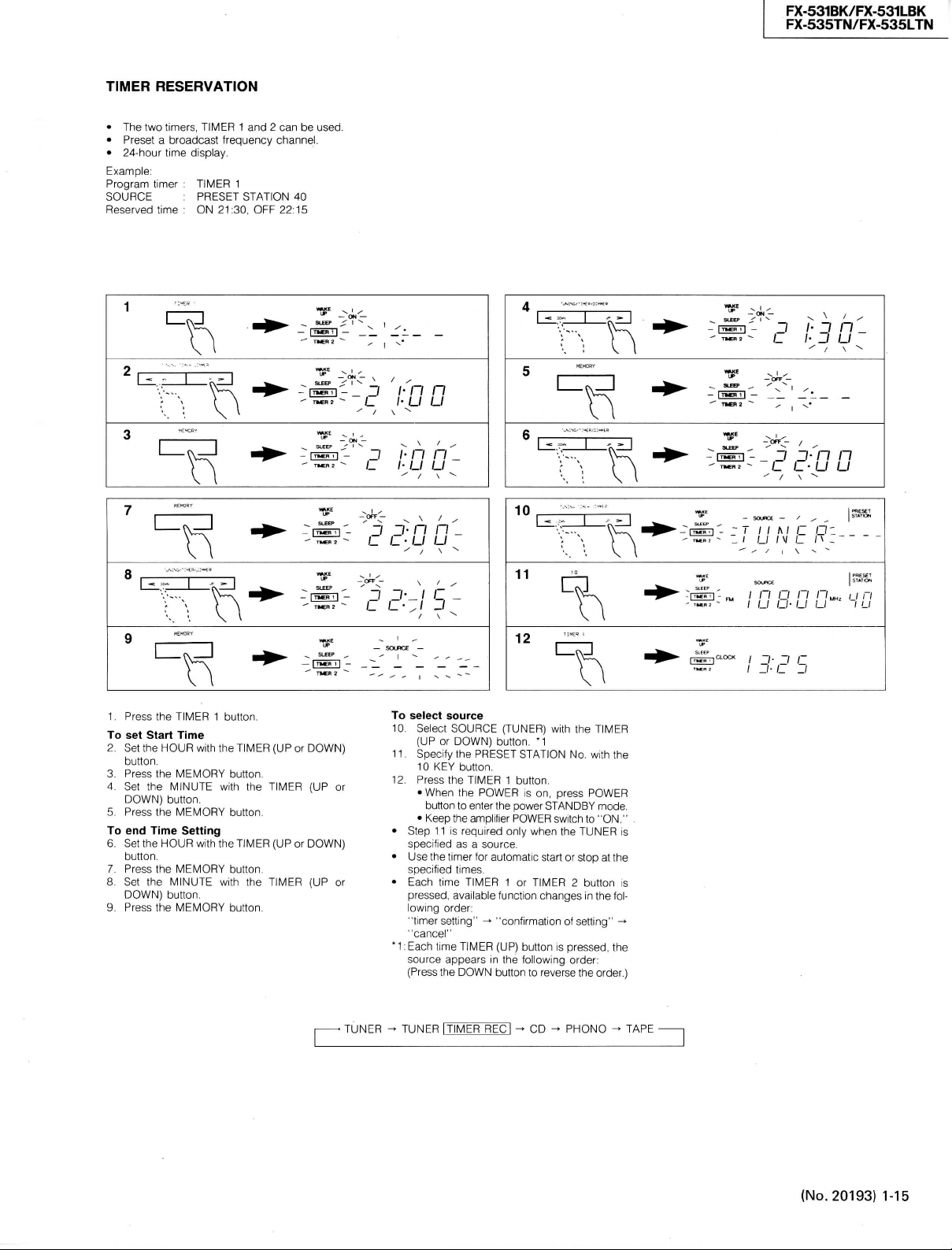
RESERVATION
•
The two
•
Preset a broadcast
•
24-hour time
Example:
Program
SOURCE
Reserved
timers,
display.
timer :
TIMER
:
PRESET
time : ON
TIMER
1 and 2 can be
frequency
1
STATION
21:30,
OFF 22:15
channel.
40
-
|mcii|
used.
3 - •
j
;•
-
>-~-c /• IJ IJ
n n
FX-531BK/FX-531LBK
FX-535TN/FX-535LTN
-^ON
—
-
- I? I- j n _
IJ
IJ
1.
Press
the
TIMER
To
set Start Time
2.
Set the
HOUR
button,
3.
Press
the
DOWN)
button.
DOWN)
MEMORY
MINUTE
button.
the
MEMORY
HOUR
the
MEMORY
MINUTE
button.
the
MEMORY
4.
Set the
5.
Press
To
end Time Setting
6.
Set the
7.
Press
8.
Set the
9.
Press
113
1 button.
with the
with the
with the
with the
TIMER
button,
button,
TIMER
button.
button.
(UP or
TIMER
(UP or
TIMER
_
3 3- n n
C /_•/_/ IJ
^
—
SLEEP
^ I ,. ,
DOWN)
(UP or
DOWN)
(UP or
10
I
11
SOURCE
—
To
select
10.
11.
12.
•
•
•
*1:Each
source
Select
SOURCE
(UP
or
DOWN)
Specify
the
10
KEY button.
Press
the
TIMER
•
When
the
button
to enter the power
•
Keep
Step
Use the timer tor automatic start or stop at the
Each
the amplifier
11 is required only when the
specified
as a
specified
times.
time
pressed,
lowing
"timer
"cancel"
source
(Press
TIMER
available
order:
setting" -* "confirmation of setting" ->
time
TIMER
appears
the
DOWN
12
(TUNER)
button. *1
PRESET
STATION
1 button.
POWER
is on,
POWER
source.
1 or
function
(ÜP)
button
in the lollowing order:
button
to
u
with the
No, with the
press
POWER
STANDBY
switch to "ON."
TUNER
TIMER 2 button
changes
in the fol-
is
pressed.
reverse
the order.)
TIMER
mode.
is
is
the
;
n O /"/ T/MH, I f n
I
U IJ- U LI I LI
13:^
El
TUNER TUNER
rTlMER
RECi
^ CD ^
PHONO ^ TAPE
(No.
20193)
1-15
Page 16

FX-531BK/FX-531LBK
FX-535TN/FX-535LTN
TUNER: Tuning to FM or AM station by setting
the timer
TUNER l TIMER RECj : Recording trom the
TUNER by setting the timer
CD:
Playing CD by setting the timer
PHONO: Playing records by setting the timer
TAPE:
Playing tapes by setting the timer
• Setting the timer
TUNER: Preset lavorite station.
CD:
Set a CD and turn on the CD player. *2
PHONO: Set a record, *3
TAPE:
Set a tape, *2
• Keep the POWER switch to "ON" of other
equipment,
• When recording with timer, carefully read the
instruction book of cassettedeck,
'2:
Playing CDs and tape deck by setting the timer
is available tor only JVC component complying with COMPU LINK,
• 3: Playing records by setting the timer is available tor:
JVC fully-automatic turntable adaptable to the
COMPU LINK
Notes:
• To reset the timer, press the CANCEL
button.
• Do not use the remote contrei until during setting of the timer to avoid errors in
operation.
• If the TUNER is used while the timer is on,
specified times are canceled.
RECORDING WITH TIMER
• Start and End of the Timer Operation
In the equipment connected with this unit using
a remote cable, the timer operation starts at the
start time preset with the timer reservation, and the
operation ends at the end time, When the timer
IS
operating, the indicator of |TIMERl| or
TIMER 2: flickers,
When the timer ends the operation, the present
time and the reservation time are displayed on the
display,
Notes:
• With POWER ON, timer function is also
available.
Example: During AM broadcast reception,
when the timer is activated, reception is
switched to FM
• The timer function of this unit can activate
only in JVC component adaptable to the
COMPU LINK.
For connecting, refer to each operational
manual.
• This unit can control the ON/OFF of connected equipments of other manufacturers or JVC's not adaptable to
COMPU LINK, thus enabling to use as a
audio timer.
Timer starting
The power is activated 10 seconds (CD: 15 seconds) before the setting time. then starts
operation.
• Recording by setting the timer is availabel only
when the source is TUNER,
1 Set a tape in the tape deck at the recording
side,
2.
Follow steps 1 to 9 of "TIMER RESER-
VATION".
3. Press the TIMER (UP or DOWN) button to
specify TUNER ItlMER'REC] as the source.
4.
Follow steps 11 and 12 "TIMER RESER-
VATION".
• Keep the POWER switch of cassettedeck to
"ON".
Care must be taken when multiple time periods
are specified. If the second period starts while the
first period is going on, the first period is canceled
automatically. (See Fig. 11)
Allow at least one minute between OFF TIME of
the first period and ON TIME of the second penod.
• Timer recording with a cassette deck having
TIMER switch (REC-OFF-PLAY).
' Set the TIMER switch of the cassette deck
to OFF.
Side A
Spur A
Cöté A
Side B
Spur B
Cöté B
• Caution for timer recording at reverse mode
ON O with a cassette deck not having
TIMER switch (REC-OFF-PLAY).
• Since the cassette deck does not have
the POWER OFF memory function, even
if the tape direction was set to rewind
( <3 ), it automtically set to forward ( > )
when the power is switched to ON.
[Example]
Timer recordings of two programs on both
sides A, B of a tape.
1.
With TIMER 1, record a 40 minutes pro-
gram on 60 minutes tape (after 30 minutes,
reversed to B). Then the TIMER 1 becomes
OFF.
2.
With TIMER 2, record another 20 minutes
program on side B.
• When starting the recording by TIMER 2,
the tape direction changes to forward and
the program is recorded on side A, con-
sequently the previous recording by
TIMER 1 is erased. (Fig. 12)
TIMER 1
TIMER 2
TIMER 1
Fig.
Abb.
12
12
ON TIME
Switching
Switching
Schaltung
Schaltung
Commutation
Commutation
OFF TIME
ON TIME
TIMER 1
TIMER 1
TIMER 2
OFF TIME
Fig.
Abb.
11
11
1-16 (No. 20193)
Page 17

HOW TO USE WAKE UP/SLEEP
FX-531BK/FX-531LBK
FX-535TN/FX-535LTN
STANDBY t
/ n Q n n„„,
/ /_/ O- LI u
SLEEP I
USING WAKE UP TIMER
• Specify the time while the power is in STANDBY mode to turn on the power at the specified time.
• WAKE UP function can be used oniy when the
source is TUNER. Preset the favorite station
and sound volume.
• Allowed time period is from 5 minutes to 12
hours.
1.
Press the POWER button to select STANDBY
mode.
2.
Press the WAKE UP/SLEEP button. (Then, the
WAKE UP indicator blinks.) M
3. Press the WAKE UP/SLEEP button again to
specify the time.
• Each time the button is pressed, the time
od changes in the following order:
0:05 ^ 0:10 0:15 ^ 0:30 - 1:00 ^ 1:30
^ 2:00 ^ . . . (After 2:00, the time period
changes in increments of hours up to 12:00.)
• The power is turned on automatically at the
specified time.
USING SLEEP TIMER
• If the timer is set while the power is on, the
POWER enters into STANDBY mode at the
specified time.
4.
Press the POWER button. (Turn the power on.)
5. Press the WAKE UP/SLEEP button. (Then, the
SLEEP indicator blinks.) *1
6. Press the WAKE UP/SLEEP button again to
specify the time.
• Each time the button is pressed, the time
changes in the following order:
0:05 ^ 0:10 ^ 0:15 ^ 0:30 ^ 1:00 ^ 1:30
2:00
• STANDBY mode is selected automatically at
the specified time.
*1:Specify the time period while the WAKE UP
or SLEEP indicator is blinking.
Note:
• If a value of more than 12 hours (12:00)
Is specified for the WAKE UP mode, or a
value of more than two hours (2:00) is
specified for the SLEEP mode, setting
mode Is reset and the frequency or clock
display reappears. In such a case, set the
time again.
peri-
• CHECK OF TIMER REMAINING TIME
1.
Press the WAKE UP/SLEEP button.
The timer remaining time is displayed for about
five seconds. Atter that, the display returns to
time display or frequency display.
Note:
• When pressing the WAKE UP/SLEEP button again before the time or frequency display returns, timer time will be extended.
• EXTENSION OF TIMER TIME
Exampie:
To extend the timer time for about 30 minutes from
the point when the remaining timer time reaches
saven minutes.
2.
Press the WAKE UP/SLEEP button.
Before the clock time display-or the frequency display returns, press the WAKE UP/SLEEP
button again.
Each time the button is pressed, the setting
time will be extended like 0:07 ^ 0:10 ^ 0:15
0:30 and the power will be turned ON or
STANDBY mode.
• START OF TIMER OPERATION
3. The timer will start operating immediately af-
ter the time setting. When the remaining timer
time reaches O minutes. the power will turn ON
or STANDBY mode.
• TIMER RESETTING
Exampie:
To listen to a broadcast channel by resetting the
WAKE UP timer.
4,
Press the POWER button to turn the POWER
ON.
ExampieTo reset the SLEEP timer.
5. Press POWER to turn the POWER STANDBY
mode.
Notes:
• Operation of the WAKE UP/SLEEP timer
has priority to operation of TIMER 1 or 2.
• This unit can control the ON/OFF of connected equipments of other manufacturers or JVC's not adaptable to COMPU
LINK, thus enabling to use WAKE
UP/SLEEP timer.
(No.
20193) 1-17
Page 18
FX-531BK/FX-531LBK
FX-535TN/FX-535LTN
OPERATION
Listening
• How to listen to broadcasts
1.
Press
2.
Set the
3.
Press
• When you don't remember of exact fre-
4-1
Afler pressing the TUNING (UP or DOWN)
• When too few stations can be tuned to by
4-2.
• When you know the frequency
4-3.
• When stations are preset
4-4 Input the required preset channel number
5,
Ad|ust the volume using the amplifier's volume
to broadcasts
the
POWER
button
to
turn
ON.
input
select
"TUNER."
the
FIvl
the desired tuned band is selected
quency
button
tor more than 1 second, release it, and
auto scanning will start. Auto
when a broadcast is received. To increase
the frequency, press the (UP)
decrease
To
stop during auto tuning, press the
ING
(UP or DOWN)
auto tuning
Tap the TUNING (UP or DOWN)
manual
tuning
cy
changes in steps of 50 kHz for FM, 9 or
10
kHz for AIvl (MW) and 1 kHz for AM (LW).
Using
this method Iets you tune to broad-
casts
that it is impossible to receive by auto
tuning.
Keep the TUNING (UP or DOWN)
pressed
until
tuned to, then tap to obtain the exact frequency,
with
the preset station
Eor
presetting broadcasts, refer to "How to
preset"
control.
button
or AM (MW/LW)
it. press the (DOWN)
button.
is performed and the frequen-
the desired frequency is almost
button,
the power
of the amplifier to
button
so that
tuning
stops
button
and to
button.
TUN-
button,
button
The
Notes:
• When the signal strength is too weak or
there is interference, auto tuning may not
be performed correctly. In this
an external antenna or use manual tuning.
. When the "AUTO/MUTE" indicator turns
off even when reception is good, stereo
broadcasts
area
when "AUTO/MUTE" indicator lights,
broadcasts
ing circuit.
Be
according
area.
• How to preset
1,
Check previously preset frequencies,
2,
Tune to the desired frequency,
For
to broadcasts",
3,
Press
The
seconds,
4,
Select one of the preset channels by
the preset channel number
tion
The
corresponding to the specified preset channel.
will be heard in mono. In an
where the signal strength is too weak,
may be eliminated by the mut-
sure to set the FM MODE/MUTE button
to the signal strength in your
tuning
to broadcasts, refer to "Listening
the MEMORY
MEMORY indicator lights for about 5
button
while the MEMORY indicator is lit,
frequency will be stored in the memory
button,
with
case,
install
imputting
the preset
sta-
Example:
1.
To select the
First
2.
To select thej_5th preset channel:
First
Note:
• After the MEMORY indicator has gone out,
even if the preset channel is recalled by
pressing
quency
• How to operate the auto memory function
1.
Press
The
seconds.
2,
Press
the MEMORY indicator blinks,
The
ly in the up direction,
If there are broadcasts, their frequencies will
be stored in memory,
• How to cancel preset channels
1,
When this
dicator
ing 10 KEY
is
lit will
was
2,
Unnecessary preset channels in which no
broadcasts
cancelled
tomaticaiiy in the preset scanning operation,
3,
For example, when FM stations have been
stored in preset channels 1 to 17 and AM
tions in preset channels 21 to 38, unnecessary
preset channeis (preset channei numbers 18,
19,
done, unused preset channels (18 to 20 and
39,
operation,
Notes:
• After being deleted, preset channels
not be recalled using the preset station
button.
• If a preset channel that has been cancelled
is
required again, store the desired frequency,
the memory operation (see page 39).
• TUNING (UP or DOWN) button described
in this instruction represents TUNING/
TIMER/DIMMER button.
2pth
press [+ 1"Ö1
press
cannot be stored in memory.
the AUTO MEMORY
MEMORY indicator blinks for about 5
any of the preset channel number whiie
frequency received changes continuous-
wiii
erase
assigned to that
20, 39 and 40) can be deleted, If this is
40) will be skipped in the preset scanning
preset channel:
button,
then press QoJ .
C+IO]
button,
then press [§] .
the preset station button the fre-
button.
button
is pressed, the
light
for about 5 seconds.
button
while the
the memory for the station that
button,
are stored can be deleted, The
preset channels
etc. in the preset channel using
CANCEL
CANCEL
wiii
be skipped au-
in-
Press-
indicator
sta-
can-
1-18 (No. 20193)
Page 19

Control System
FX-531BK/FX-531LBK
FX-535TN/FX-535LTN
COMPU LINK
CONTROL SYSTEM
COMPU LINK Control System
linked system
individual COMPU LINK Components*
dio system
related
system components witfiout requiring
component,
To generate tfiis automatic souroe selection, con-
nect
source components,
and play a selected source automatically
simple one-touch
the amplifier
tivation button
pose.
the previous source component will stop playing
within about five seconds.
• The COMPU LINK Component
Notes:
•
Abnormal operation will result jf the pow-
•
Ensure that the COMPU LINK-1/SYNCHR0
INFORIWATION FOR THE CUSTOIMERS WHO
HAVE NOT PURCHASED OUR COMPU
LINK REMOTE CONTROL COMPONENTS
YET.
COMPU LINK Control System
stepped
able"
dition
Remote Control Component"), Using this upgraded system (named "COMPU LINK Remote
trol System"), virtually every function
A/V system
source
handheld remote control unit,
tion,
in
whicti ttie computer operates
to
effect control.
to
ttiis unit
is
ttie one-toucfi selection
the
provided remote cables
When the sources have been switched over,
meet
the
• Manufactured
• Equipped with COMPU LINK-1/SYNCHR0
terminals which
tem sources synchronously operate with
provided remote cables,
er supply of one of the components is interrupted halfway. If this happens, push
the activation button again to restart.
terminal of each component is connected
with the attached remote cable. Be sure
to read the instruction manual for each
component very carefully.
up to a
audio/video (A/V) system with the simple ad-
of a
and
consult your
and
of
the souroe selector button
or
receiver. You
of any
desired source
following requirements:
by JVC,
are so
comprehensive "remote controll-
component (named "COMPU LINK
can be
controlled from
from where
JVC
is a
computer-
tfie features
any
to
connect
also use the
tor
is
can
in
any
seated with
For
more informa-
of an au-
of all
"tiost"
at the
this
required
all
easily
Con-
the entire
desired
One of
you can switch sources
can
designed that
you are
dealer.
on
all
of
ac-
pur-
to
sys the
be
a
COMPU LINK
BEDIENUNGSSYSTEM
Das COMPU LINK Bedienungssystem
Computer-verbundenes System,
ter einzeine COMPU LINK Steuerkomponenten*
einer Audio-Anlage steuert. Dieses Betriebssystem
macht samtliche Aniagenkomponenten
einzigen Tastendruck verfügbar, ohne
"zentrales" Bauteil vennoten ware.
Automatische Quellenwahl
die mitgelieferten Verbindungskabel
Aniagenbauteile anschlieBt. Die Tonquellen lassen
sich dann umschalten
Druck
auf die
oder Receivers nach Belieben automatisch betatigen.
Betriebstaste des gewünschten Bauteils drücken.
Nach dem Umschalten der Tonquelle wird
trieb
des
fünf Sekunden abgebrochen.
• COMPU LINK Komponenten mussen folgende Bedingungen erfüllen:
• Hergestellt
• Ausstattung
Achtung:
•
Der Betrieb wird gestort, wenn man die
Stromversorgung eines der Bauteile mittendrin unterbricht. In soich einem Fall ist
die Betriebstaste zum Neustart noch einmal zu drücken.
•
Vergewissern Sie sich, daB die COMPU
LINK-1/SYNCHRO-Buchsen einer jeden
Komponente an dem mitgelieferten Fernbedienungslcabel angeschlossen sind. Lesen Sie die Bedienungsanleitung einer
jeden Komponente sorgfaltig durch.
INFORMATIONEN FÜR DIEJENINGEN UNTER
UNSEREN KUNDEN, DIE DAS COMPU LINK
FERNBEDIENUNGSSYSTEM NOCH NICHT
BESITZEN.
Das COMPU LINK Bedienungssystem laBt sich
leicht ausbauen
bedienbaren" Audio/Video-System (A/V), indem
man
PU LINKSteuerkomponente") hinzufügt, Mit dem
solchermaBen ausgebauten System (names
"COMPU LINK Fernbedienungssystem") können
Sie nahezu jede Funktion im gesamten A/V-System
von Ihrem Sitzplatz
Tonquelle
dienungsgerats steuern, Einzelheiten dazu erlautert gerne
Quellenwahltaste
Zu
diesem Zweck können Sie aber auch
vorigen Aniagenbauteils innerhalb
von JVC,
Buchsen,
deren Konstruktion samtliche Anlagentonquellen über
bindungskabel synchron funktionieren laBt,
zu
nur ein
einziges Bauteil (namens "COM-
mit
Hilfe eines handgeführten Fernbe-
Ihr
JVC-Handler,
ist
möglich, wenn
und mit
mit
COMPU LINK-1/SYNCHR0-
die
einem allumfassenden
aus und ber
ist ein
wo der
Compu-
mit
einem
daB ein
man
an
samtliche
einem einzigen
des
Verstarkers
die
der
Be-
von
mitgelieferten Ver-
"fern-
jede beliebige
SYSTEME
DE
COM-
MANDE COMPU LINK
Le système
système
agit
audio afin
ristiques
tionner
a
un
Pour pouvoir utiliser cette fonction
tomatique
cables
tous
tionner une source d'entrée
cer
pression
OU
d'utiliser
d'entrée désirée. Lorsqu'une source d'entrée
sélectionnée,
source d'entrée sélectionnée précédemment
s'arrête dans
• L'élément COMPU LINK doit satisfaire
Remarques:
•
Si la tension disparait sur l'un des élé-
•
S'assurer que la borne COMPU
INFORMATIONS DESTINESS AUX UTILISATEURS QUI
NOS ELEMENTS A TÉLÉCOMMANDE COMPU
LINK.
Le système
facilement être transformé
audio/vidéo (A/V) "télécommande".
système amelioré (appelé "Système
mande COMPU LINK"),
mander pratiquement toutes
système
d'entrée ainsi
en utilisant
tez votre revendeur
de
commande COMPU LINK
de
liaison utilisant
sur
les éléments COMPU LINK* d'une chaine
de les
de
cedt appareil est
un
élément
élément "höte".
de
source d.entree
de
télécommande fournis pour raccorder
les
éléments,
la
lecture automatiquement
du
selecteur d'entrée
de
ramplificateurtuner.
la
touche d'activation
la
les
points suivants:
• Fabriqué
• Equipe
ments au cours de cette operation, le
fonctionnement sera anormal. Si cela se
produit, appuyer une nouvelle fois sur le
bouton d'activation pour continuer.
SYNCHRO de chaque élément est raccordé avec le cable de téléconnexion qui
a été fourni. Lire attentivement le manuel
d'utilisation de chaque élément de la
chaine.
par
de
chronisation (COMPU LINIK-1/SYNCHR0)
qui sont prévues pour que tous les éléments
d'entrée
de la
synchronisation lorsqu'ils sont raccordés
'aide des cables
N'ONT
de
A/V a
partir
qu'a
une
un
micro ordinateur qui
commander,
de la
II
est ensuite possible
lecture
cinq secondes
JVC,
bornes
commande COMPU LINK peut
partir
unité
JVC
Une des
la
possibilité de sélec-
chaine sans faire appel
il
faut connecter
et de
par une
de
II est
qui
était
de
COMPU LINK-1/syn-
chaine fonctionnent
de
télécommande fournis,
PAS ENCORE ACHETE
en un
il est
possible
les
de
n'importe qujelle source
de la
de
position d'écoute
télécommande. Consul-
poour plus
est un
caracté-
de
selection auj-
les
de
sélec-
faire commen-
simple
l'amplificateur
aussi possible
de la
source
cours
sur la
suivent,
LINK-1/
système
utilisant
de
télécom-
de
de
détails.
est
les
en
com-
du
en
qui
En
fonctions
a
ce
(No.
20193)
1-19
Page 20

FX-535TN/FX-535LTN
FX-531BK/FX-531LBK
1-20 (No. 20193)
1.
Block Diagram
Page 21

2.
Exploded View andRemoval Procedures
FX-531BK/FX-531LBK
FX-535TN/FX-535LTN
• Removing the Top cover
1.
Remove 6
(4
screws
© on the
2.
Disconnect
its
sides
screws
® on the both
rear)
and
fixing
the top cover by
lifting
the
the top cover.
sides
and 2 screws
slightly
rear.
• Removing the Front panel
1.
Remove the top cover.
2.
Remove 3
the
front
3.
Remove 2
the
front
screws
panel.
rivets
panel.
(3)
from the lower
® from the
upper
opening
part
of
part
of
• Removing the Logic control & switch
PCB
1.
Remove the front
2.
Remove 5
3.
Remove the logic control &
screws
panel.
©.
switch
PCB.
• Removing the Front switch PCB
1.
Remove
2.
Remove 2
3.
Remove the front
the
front
screws
panel.
©.
switch
PCB.
• Removing the Tuner PCB
1.
Remove the top cover.
2.
Remove 4
3.
Remove 3
screws
screws ® securing
® from the
rear
the
panel.
tuner
PCB.
(No.
20193) 1-21
Page 22

FX-531BK/FX-531LBK
FX-535TN/FX-535LTN
3, FM / MW / LW
W116 \ W117
I
I
I
I
W118 wn9
TPin
TP1M
•W)20
—— W)20 —
• W121
•W122
W122 —-1
• W123
TP113
Tuner Alignment Procedures
IC104
T101
©
TC 105
T102
TC106
Tl 04
TP102
VTUNE
B
Tl 03
T105
T106
IC103
B
T107
W130
W129
FM
CENTER
ENA-097-1
W158
W159
FE101
(1) FM Front-end Section
1.
Set the frequency display to "108.0 MHz" and the FM
MODE
switch to "MONO" position.
2. Confirm that there is
3. Confirm that the output of test point "TP102" is 8.0 + 2
V.
4. Set the frequency display to "87.5 MHz" and confirm
that
the output of test point "TP102" is
(2) Center Meter and Distortion
FM
detector
1.
Connect a center-meter or a digital voltmeter to test
2. Adjust T105 so that the center-meter indicates "O" or
3. At the same time, adjust T106 so that the distortion of
(3) LW Section (for Europe only)
LW
oscillator coil : T104
1.
Set the frequency display to "144 kHz".
2. Adjust T104 to obtain
3. Set the frequency display to 353 kHz and confirm that
LW
antenna coil : T102
4. Connect a
5. Adjust T102 to obtain the
LW
antenna trimmer : TC106
6. Adjust TC106 to obtain the
1-22 (No.
20193)
coil : T105,T106
point
"TPlOl",
modulation, 75 kHz deviation) with SSG ATT 70dB.
the digital voltmeter reads 0 + 1 mV.
the audio output is minimized.
the output of test point "TP102" is 7.7 ± 0.6 V.
the rear panel.
164
kHz.
353 kHz.
and tune to a 100.1 MHz signal
loop
antenna to the "AM
noise
with no input signal.
0.8±0.1
V at test point "TP102".
best
reception sensitivity at
best
receiving sensitivity on
1.6±1.0V.
LOOP"
(IkHz
terminal on
(4) MW Section
Before
proceeding
alignment referring to items
ment, repeat the MW alignment to make sure of the result.
Note:
[ ] :for
(
) :for Other areas (Channel spacing switch : 9 kHz)
MW oscillator coil : T103
1.
Set the frequency display to [522
confirm that the output of test point "TP102" is
[0.9±0.1V](1.0±0.1
2. Set the frequency display to [1629
confirm that the output of test point "TP102" is
[7.5 + 0.8
MW antenna coil
3. Connect a
the rear panel.
4. Adjust
603 kHz.
MW antenna trimmer : TC105
5. Adjust TC105 to obtain the
1404 kHz.
(5) Separation
1.
Tune to a 98.1 MHz
2. Adjust VR167 so that the channel separation
maximum.
(6) Timer's
Oscillator trimmer :
1.
Unplug the
2. By using
3. After confirming tuner's FL display is
frequency counter to
4. Adjust
to do the MW alignment,
Australia,
V]
(7.2 ±0.7
loop
TlOl
to obtain the
clock
frequency
power
diode,
TC501
concerned.
the U.K. and Continental Europe
V).
V).
TlOl
antenna to the "AM
stereo
TC501
cord.
connect
TPlll.
to 52428.8 Hz ±0.2 Hz.
complete
After the LW align-
kHz]
(531 kHz) and
kHz]
(1602 kHz) and
LOOP"
best
reception sensitivity at
best
reception sensitivity at
signal.
(on the Logic
to
TPn2.
control&
(See figure)
"OFF",
the LW
terminal on
becomes
switchPCB)
connect
a
Page 23

END-059-4
AC Outlet PCB
O
O
END-059-2
Front
Switch
PCB
WTSO,
WT802
Ir
I®
®
FWI04®
JI02
5
4
©
©
I
FWI03
©
Tuner PCB
ENA-097- I
ENA-097-2
Logic Control &
®©
©
Switch
@
FWIOI FWI05
PCB
LmtTtTTJ^S
®©
©
O
3
3
@
n n a
Page 24

FX-531BK/FX-531LBK
FX-535TN/FX-535LTN
5. Internal Connection of FL Tube
•
FL501:
(1)
Grid
ELU0001-099
Division
WAKE
UP
SLEEP
' a n ' a r~a '
Ü^PMAM
8
G
(2)
Terminal Connection
Terminal
Electrode
Terminal
Electrode
(3)
Internal Connection
No. 1
No.
TIMER
ON
F F
(Notes)
REC
OFF
-7
rilt
2
3 4 5
NP
F
G
P
lil ' Hj\lll i%t
7
G
p
(SO)
19
20
5G
NC NC
Filament
Grid
Anode
I TUNED
SOURCE
6
G
6
P
8G
(SI)
21
22
4G
NP : No Pin
NC : No
AUTO/MUTE
I
' I '
5
G
7
8
9
P
P
(S3)
24
8G
25
3G
(S2)
23
P
(S6) P (S5)
Connection
STEREO
4G 3G
10 1 1
p
(S4) P (S7)
27
26
NC
NC
MEMORY
CANCEL
'rlAt
12
7G
28
3G
13
P
(S8)
29
NC
14
(S9)
30
2G
MHz
KHz
15
16
P
6G
31
NC
P
(S10)
32
1G
17
18
P
NC
(S11)
33 34 35 36
NC NP F F
8G 7G 6G 5G
SO CLOCK
SI
S2
S3
S4
S5
S6
S7
S8
S9
S10
SI
1
FM
AM
PM
Frame
of
TIMER 1
Frame
of
TIMER 2
Frame
of
WAKEUP
Frame
of
SLEEP
WAKE UP,SLEEP
TIMER1JIMER2
iJ
ON
OFF
TIMER REC
1,1
SOURCE
TUNED
h, k
AUTO/
MUTE
STEREO
UP
4G 3G 2G
i,l
MEMORY
CANCEL
MHz
kHz
1G
PRESET
STATION
1-24
(No.
20193)
Page 25

FX-531BK/FX-531LBK
FX-535TN/FX-535LTN
6. Internal
IC501:
LC6538D-4522
Block
(System
Diagrams
Controller)
IC501 LC6538D-4369
FL
Segment
FL
Grid
of
Major
FL
Segment
oNegative
Power Supply
ICs
IC501 : LC6538D-4522
1
' '
r
IPin
No.
1
1
!
2
i
3
1
4
1
5
1
6
1
7
1
8
1
9
1
10
1
11
1
12
1
13
1
14
1
15
1
16
1
17
1
18
1
19
1
20
1
21
1
22
1
23
1
24
1
25
1
26
1
27
1
28
1
29
1
30
1
31
1
32
Naae
SlO
SU
Vdd
OSC
OSC
Vss
TEST
RES
KO
KO
KO
KO
KO
KO
KO
KO
KI
KI
NC
NC
NC
T8
T7
16
T5
14
T3
T2
Tl
TO
1
XI
NC
0
1
2
0
1
2
3
4
5
6
7
1
1
I/O
1
0
1
0
i
-
1
-
1 --
1
0
1
0
1
0
1
0
1
0
1
0
1
0
1
0
1
0
1
-
1
I
1
0
1 -1
-
1
I
1
_
j
-
i 0
i 0
1
0
1
0
1
0
1
0
1
0
1
0
1
I
1
I
1
1
Atv
H
-
_
H
-
H
H
H
H
H
H
H
H
H
-
-
-
_
-
L
L
L
L
L
L
L
L
L
L
i
Teminal
Function
FL segaent output
segMent
grid
output
grid
output
grid
output
grid
output
grid
output
grid
output
grid
output
grid
output
grid
output
supply
•atrix
•atrix
•atrix
•atrix
•atrix
•atrix
Batrix
output
output
output
output
output
output
output
output
output
IFL
IFL
IFL
IFL
IFL
IFL
IFL
IFL
IFL
IFL
I
Power
iOscillator
jOscillator
1Ground
iTest
iReset
iKey
IKey
Uey
IKey Matrix
IKey
IKey
IKey
IKey
IKey input
IKey input
1 1
1 1
1 1
1 1
1 1
1 1
1 1
1 1
1 1
1 1
1
i
1 1
i 1
II
II
1 1
II
1 1
1 1
1 1
1 1
1 1
1 1
1 1
1 1
1 1
1 1
1 1
1 1
II
1
1
1
1
11
11
1
Pin
No.
1
Nane
1
S9
64
63 1 S8
62 1 -Vp
61 1 S7
60 1 S6
1
55
59
53 1 S4
57 1 S3
56 1 S2
55 1 SI
1
SB
54
53 1 NC
52 1 NC
51 1 TEST
50 1 NC
1
49
36
DCS OUT
i
OUTLET
48
47 1 MUTE
46 1 CE
1
NC
45
1
C8
44
43 1 DO
42 1 Dl
41 1 KO 10
40 1 KO 9
1
KO 8
39
1
DCS IN
38
ISIEREO
37
ITUNED
35 1 INH IN
1
KI 3
34
1
K! 2
33
I/O
0
0
-
0 H IFL
0 H IFL
0
0
0 H IFL
0
0 B IFL
0 U IFL
- -
- -
0 L lx'tal
OÜT
-
0
0
0 H InUTË
0
- -
0
0
I
0
0 L
0 L
I
IN I L
IN
I
I
I
I
1
]
Atvl
Terainal
1 i
H
1FL
segment
H
1FL
segaent output
-
1
Power
seg«ent
segment
1
1
H
iFL
segment
H
1FL
segment
segment
H
1FL
segment
segment
{
1
segnent output
1
1
1
1
-1 1
1 1
1
1
H
IDCS
signal
H
1
"STANDBY","ON" indication
H
iInterface
1
1
[
j
H
1
Interface
B
1
Interface
L
1
Interface
L
1Ini
tia 1 diode
llnitial
jlnitial
IDCS
signal
L
ISIEREO
ITUNED
L
n
JINH
input
IKey input
L
L
IKey input
Function
output
supply
for FL |
output
output
output
output
output
output
output
frequency
output
signal
output
to
LC7218
to
LC7218
to
LC7218
to
LC7218
1
diode
1
diode
|
input
display
display,
1
j
j
1
|
|
|
|
|
|
|
|
|
[
adjust^entl
|
|
|
1
1
1
1
|
input
|
auto-stop
|
(No.
20193)
1-25
Page 26
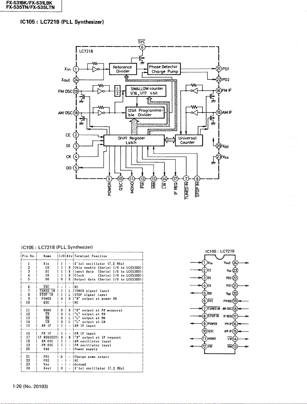
FX-531BK/FX-531LBK
FX-535TN/FX-535LTN
IC105 : LC7218
(PLL Synthesizer)
SYC
IC105 : LC7218
iPin
No.
1
1
1
2
1
3
1
4
1
5
1
6
1
7
1
8
1
3
1
10
1
11
1
12
1
13
1
14
1
15
1
16
1
17
1
18
1
19
1
20
1
21
1
22
1
23
1
24
1-26
(No.
20193)
(PLL Synthesizer)
Name I/O
Xin I
CE I H IChip enable (Serial
Dl I U 1 Input data (Serial
CK 1 H ICIock (Serial
DO 0 H
SÏC
TUNED
Ifi
STOP
IN
POWER 0 II
OSC
NONO 0 H 1 1"H"
FH
m
AM
IF
FH
IF
IF REOUEST 0 H
AM
OSC
FM
OSC
Vdd
PDl
PD2
Vss
Xout
1
Atv 1 Terminal Function
1
-
IX'
tal
oscillator
lOutput data (Serial
1
_ _
INC
1 L ITUNED sUnal input
I L ISTOP signal input
|"H"
output
iNC
- -
1
0 L output
0 L
0 L
I -!AM
I
I
I
- -
D
- -
- -
0 -IX'tal oscillator
output
TL"
output
1'L'
output
IF
input
-
IFM
IF
input
|"H"
output
1
AM
osei I Ia
-
IFM oscillator input
-
iPoHer
supply
_
ICharge puMP output
INC
1Ground
at
poHer
at FM
at FM
at MW
at LH
at IF
tor
input
(7.2
HIIz)
I/O to
I/O to
I/O to
I/O to
ON
«onaural
request
(7.2 Mz)
LC6538D)
LC6538D)
LC6538D)
LC6538D)
IC105: LC7218
Page 27

FX-531BK/FX-531LBK
FX-535TN/FX-535LTN
IC801:
AN7812R
L.
AN7812R
UJ
z
O
ÜJ
tr
Q;
3
O
<
CU
REFERENCE
VOLTAGE
^
(Regulator)
OUTPUT
PASS
OVERCURRENT
PROTECTOR
-<2)
GND
IC103:
COMPARATOR
®-
Vout
LA1266A
THERMAL
PROTECTOR
-Wr-
Reset
(FM/AM IF & Det.)
IC802:
AN78M06
AN78M06
3^
REFERENCE
VOLTAGE
|3
< a.
FM
DET
(Regulator)
OUTPUT
PASS
OVERCURRENT
PROTECTOR
LA1266A
-J\AAr-
COMPARATI
1
Rsc
THERMAL
PROTECTOR
IC104 : LA3401
Vcc
VCO
Vcc
VCO LPF LPF
AM
IN FM IN
-(23)--(ï?
(3)—Ci)—(5)—(i
Pilot Sepa.
OUT
I
@ @ @
(FM MPX)
PLL Pilot Pilot
IN
3?)
LOUT
Adj.
AM
Vref
OSC
Det Det IN
(17) (Ï6) (15) (O (Ï3) (Ï2>
X
Mute Stereo
Mute
LED GND
R
ROUT
Vcc
FMAM Muling
ON Change
Mute over
OUT
ADJ
BA401(IC101,102):IFAMP
(No. 20193)
1-27
Page 28

Page 29

Page 30

Page 31
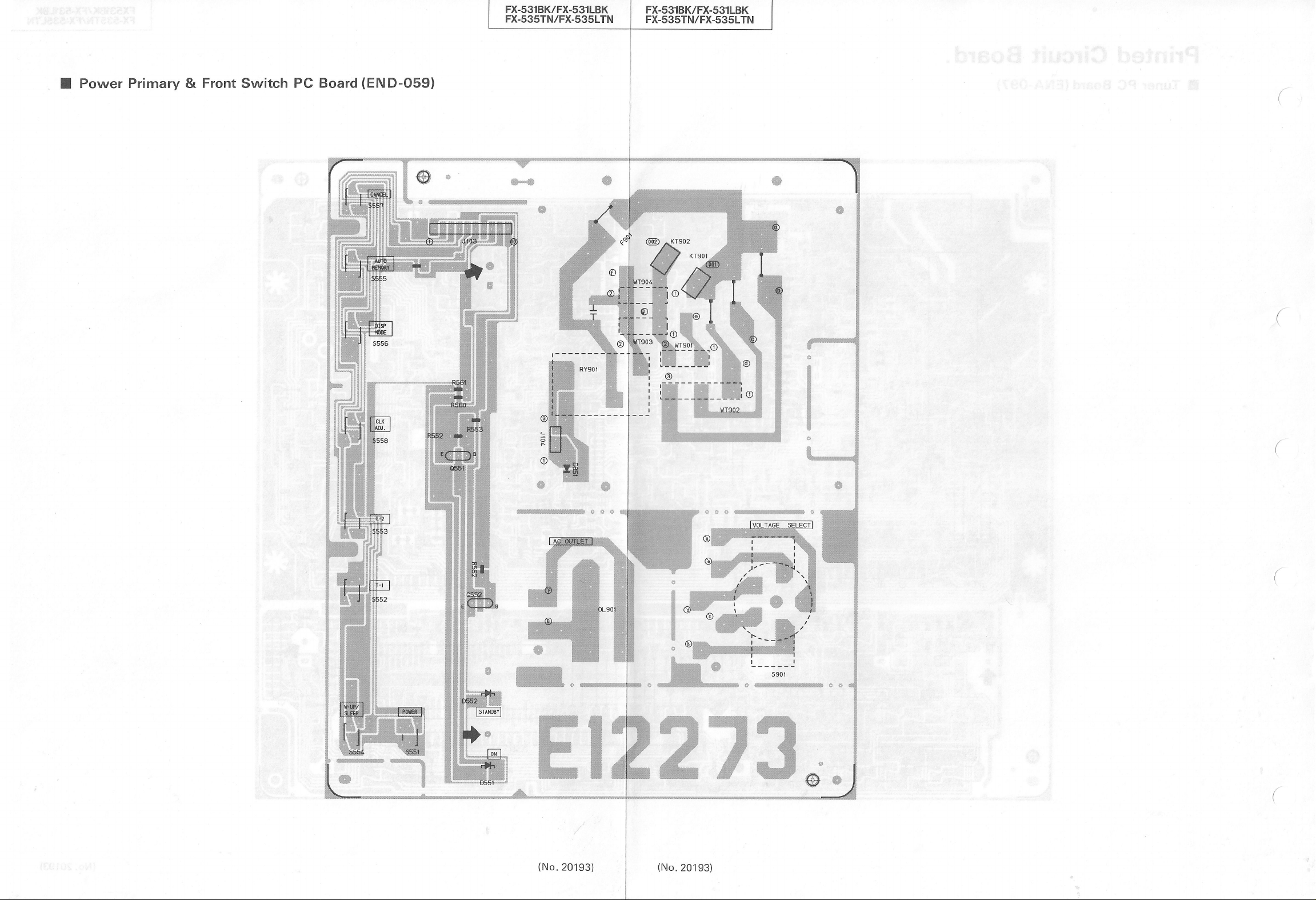
Page 32

PARTS LIST
FX-531BK/FX-531LBK
FX-535TN/FX-535LTN
Contents
General Exploded View and Parts List 2-3
Printed
Accessories List 2-13
Packing Materials and Part
Circuit Board Ass'y and Parts List 2-7
• ENA-097 Qluner
• END-059 QPower Primary & Front Switch
PC
Board Ass'y 2-7
PC
Board Ass'y 2-11
Numbers
2-14
(No. 20193) 2-1
Page 33

FX-531BK/FX-531LBK
FX-535TN/FX-535LTN
2-2 (No.
20193)
Page 34

Page 35

FX-531BK/FX-531LBK
FX-535TN/FX-535LTN
• FX-531LBK Parts List
Item Part Number Part Name
EFP-FX531LBKE
1
1-1 E26719-002 Front Panel 1
1-2 E26721-001SS Push Button 1 Power
1-3 E26723-003SS Push Button 1 Preset
1-4 E306781-001SS Button Escutcheon 1 Power
1-5 E306782-003SS
1-6 E306784-001SS Button Escutcheon 1 Preset
1-7 E306785-001 Window Screen 1
1-8 E60912-003 Speed Nut 1
1-9 E73522-001 Indicator 1
1-10
1-11 E75934-001 Indicator 1 Stand By
1-12 E72968-001 JVC Mark 1
A
/K
$
A
A
A
The Marks Designated Areas
LG West Germany (with LW) LE , LEF Continental Europe
LBS the U.K. (with LW) No mark indicates all areas.
E75584-007SS
2 SBSG3008M Screw 12
3 E48729-009 Plastic Rivet 2 for Front Panel
4 EXO050005N40S02 Feit Spacer 3 for Front Panel
5 SDSF2608Z Screw 7
6 E26728-002SS Metal Cover 1
7 E61660-004 Special Screw 4 for Metal Cover
8 E306788-001SS Side Bracket 1 Right
E75931-001SS
9
10 SBSG3008N Screw 21
11 E26725-001SS Bottom Plate 1
12 E70115-002 Caution Label 1
13 E75088-003 Foot Ass'y 2 Front
E75088-004 Foot Ass'y
14
15 SBST3008N Screw 4 for Foot
16 E306789-001.SS Center Bracket 1
17 E303843-001 Wire Clamp 1
18 E306787-001SS Side Bracket 1 Left
ETP1000-65EA
19
ETP1000-65EABS Power Transformer 1 PT001 LBS
20 E65389-002 Special Screw 2 for Trans Except LG
E65389-005 Special Screw 2 for Trans LG
21 E406228-001 Spacer 2 LG
22 E306791-001SS Circuit Board Bracket
23 E26726-003SS Rear Panel 1 LBS
E26726-004SS Rear Panel 1 LG
E26726-009SS Rear Panel 1 LE,LEF
24 E73562-003 Special Screw 1
25
Please refer to the f llowlngs.(*)
26 E406079-001
27 EMC0236-001 AC Socket 2 LE.LEF.LG
EMC0237-001BS AC Socket 2 LBS
28 QHS3876-162 Cord Stopper
QHS3876-162BS
29 QMP3900-200 Power Cord 1 LE.LEF.LG
QMP9017-008 Power Cord 1 LBS
—
E61029-005 Number Label 1
—
E74792-066 FTZ Label
E70028-001
-
Front Panel Ass'y 1
Push Button
FL Screen
Bracket 2
Power Transformer 1
ACOutlet Cover
ACOutlet Cover
Cord Stopper
Approval Label
Q'ty
Description Areas
1
Up/Down
1
2 Rear
PT001 LE,LEF,LG
1
2 LBS
1
1
1
1
LE.LEF.LG
LBS
LG
LE
A: Safety Parts
(*) This screw (Item 25) is used for only this FX-535TN.
(No.
20193) 2-5
Page 36

•
FX-535TN/FX-535LTN
Item
A
1 EFP-FX535TNU
1-1
1-2
1-3
1-4
1-5
1-6
1-7
1-8
1-9
1-10
1-11
1-12
2 SBSG3008M
3
4
5 SDSF2608Z Screw 7
6
7
8
9
10
11
12
13
14
15
16
17
18
A
19
A
A
20
21
22
23
—
24
25
26
A
27
A
A
A
28
A
A
29
A
A
A
—
—
-
The
Marks
A Australia LBS the U.K. (with LW)
U OtherCountries LE,LEF Continental Europe(with LW)
LG
West
Designated
Part Number
EFP-FX535LTNE Front Panel Ass'y 1
E26719-003
E26719-004
E26721-003SS
E26723-005SS
E306781-002SS
E306782-004SS
E306784-002SS
E306785-002
E60912-003
E73522-001
E75584-007SS
E75934-001
E72968-001
E48729-009
EXO050005N40S02
E26728-004SS
E61660-004
E305788-001SS
E75931-001SS
SBSG3008N Screw
SBSG3008IM Screw
E26725-001SS
E70115-002
E75088-017
E75088-017
SBST3008N Screw 4 for Foot
E306789-001SS
E303843-001
E306787-001SS
ETP1000-65EA
ETP1000-65HA
ETP1000-65EABS
E65389-002
E65389-005
E406228-001
E306791-001SS
E26726-011SS
E26726-006SS
E26726-007SS
E26726-008SS
E26726-010SS
E303260-214
E73562-003
SDSG3008N Screw 2 U
E406079-001
EMC0233-001
EIV1C0236-001
EMC0237-001BS
QHS3876-162
QHS3876-162BS Cord Stopper 1 LBS
QMP7520-200
QMP2560-244
QMP3900-200
QMP9017-008BS
E61029-005
E74792-067
E70028-001
Germany (with LW) No mark indicates all areas.
Parts List
Part
Name
Front Panel Ass'y
Front Panel 1
Front Panel 1
Push Button 1
Push Button
Button Escutcheon
Push Button
Button Escutcheon
Window
Screen
Speed
Nut 1
Indicator 1
FL
Screen
Indicator 1
JVC Mark 1
Screw
Plastic
Rivet 2 for Front Panel
FeltSpacer 3 for Front Panel
Metal
Cover 1
Special Screw 4
Side
Bracket 1 Right
Bracket 2
Bottom
Plate
Caution Label 1
Foot Ass'y 2 Front
Foot Ass'y 2 Rear
Center Bracket 1
Wire
Clamp 1
Side
Bracket
Power
Transformer 1
Power
Transformer 1
Power
Transformer 1
Special Screw 2 for Trans
Special Screw 2 for Trans LG
Spacer 2
Circuit
Board Bracket 1
Rear Panel
Rear Panel 1 A
Rear Panel
Rear Panel 1 LG
Rear Panel 1 LE.LEF
Rating Label
Special Screw 1
ACOutlet Cover 2 LBS
AC Socket 2 A
AC Socket
AC Socket 2 LBS
Cord Stopper 1
Power
Cord 1 U
Power
Cord
Power
Cord 1
Power
Cord 1 LBS
Number Label 1
FTZ
Label 1 LG
Approval Label
Areas
A: Safety PartS
2-6 (No. 20193)
Q'ty
1
1 Preset
1
1
1 Preset
1
1
5
28
30
1
1
1
1
1
2 LE.LEF.LG
1 A
1 LG
Description
Power
Power
Up/down
Stand By
Stand By
for
Metal
Cover
Left
PT001
PT001
PT001
Made
in Singapore U
A,U
LE,LEF,LBS,LG
A,U
ExceptU
U
Except
A,LE,LEF,LG
U
LBS
Except
LG
U
LBS
Except
Areas
LE.LEF.LBS.LG
A
LG
LBS
Except
U,A, LBS
Page 37

Printed Circuit Board Ass'y and Parts List
• ENA-097 • Tuner PC Board Ass'y
Note
: ENA-097 • varies according to the areasemployed. See note (1) when placing an order.
FX-531BK/FX-531LBK
FX-535TN/FX-535LTN
(No.
20193) 2-7
Page 38

FX-531BK/FX-531LBK
FX-535TN/FX-535LTN
Note(l)
•
FX-531LBK
PC
Board
ENA-097
ENA-097
ENA-097
•
FX-535TN/FX-535LTN
PC
Board
Ass'y
Dl
üü
F|
Ass'y
ENA-097[B]
ENA-097[C]
ENA-097[D]
ENA-097||]
ENA-097[F]
Transistors
ITEM
PART
NUMBER D E S C
8103
2SC',61<C)
Q104
2SC53S(B,C) SILICON
Q104
2SC535(B^C) SILICON
Q105
2SC461(B,C) SILICON
Q105
2SC461(B,C) SILICON
Qlll
2SD1302
CS^T)
2SD1302(S^T)
2SD1302(S,T) SILICON
2SK301CQ,R)
2SK301(a,R)
2SK301C8,R)
2SK301(P,8)
2SK301(P,a)
2SK301(P,a)
2SK301(P,a)
2SK301(P,a)
2SK301(P,a)
flNlL4M
AN1L4M
AN1L4M
AN1L4M
AN1L4M
2SK301(82)
"AA1L4M
2SD1302(S,T) SILICON
2SD1302<S^T)
2SA564A<R^S)
AA1L4M
AA1L4M
AN1A4P
AA1L4M
2SC1685(R,S) SILICON
2SB621(a,R,S)
2 501685
CR,S)
PART
NUMBER D E S C R I P T I 0 N
BA401
BA401
LA1266A
LA3401
LC7218
LC6538D-4522
AN7812R
AN78M06
PART
NUMBER D E S C R I- P T 0 N
I.C.s
Diodes
A
2-8 (No.
Qlll
Qlll
Q112
8113
8113 2SK301(Q,R)
Q113
Q114
Q114
Q114
Q115
Q115
Q115
8121
8121
8121
8123
ai2A
Q125
8126 2SC1685C8-S)
8127
8131
8132
8133
Q134
8135
8501
8502
8503
8801
8802
ITEM
ICIOI
IC102
IC103
1C104
IC105
1C5Ö1
IC801
IC802
ITEM
D102 1SS133
D102 1SS133
D102 1SS133
D103 1SS133
D103 1SS133
20193)
Designated
Continental
West
Germany
the
U.K.
Europe
(with
LW)
Designated
OtherCountries
Austraria
Continental
West
Germany
the
U.K.
SILICON
SILICON
SILICON
F.E.T
F.E.T
FVË'
F.E.T
F.E.T
F.E.T
F.E.T
F.E.T
F.E.T
F.E.T
SILICON
SILICON
SILICON
SILICON
SILICON
F.E.T
SILICON
SILICON
SILICON
SILICON
SILICON
SILICON
SILICON
SILICON
SILICON
SÏircON"
I.C.
I.C.
l.C.
I.C.
I
.C.
I.C.'
I
.C.
I.C.
SILICON
SILICON
SILICON
SILICON
SILICON
(with
T
Europe
LW)
R
I P T I 0 N
HITACHI
HITACHI B
HITACHI
HITACHI
HITACHI
MATSUSHITA
MATSUSHITA
MATSUSHITA
MATSUSHITA
MATSUSHITA
''HAtSUSHITA
MATSUSHITA
MATSUSHITA
MATSUSHITA
MATSUSHITA
MATSUSHITA
MATSUSHITA
MATSUSHITA
NEC
NEC
NEC
NEC
NEC
MATSUSHITA
NEC
MATSUSHITA
MATSUSHITA
MATSUSHITA
NEC
NEC
NEC
NEC
HATSUSHITA
HAISUSHITA
hSisüsiiiïs
"
ROHM
ROHM
SANYO
SANYO
SANYO
MATSUSHITA
MATSUSHITA
ROHM
ROHM
ROHM
ROHM
ROHM
Areas
(with
Areas
(with
(with
LW)
(with
LW)
LW)
LW)
AREA
C
B
C
D
E
F
D
É
F
D
E
F
D
E
F
D
E
F
AREA
AREA
D
Diodes
ITEM
PART
A
0103
01O4
0105
D106
D107
D108
D109
D109
D109
DllO
DllO
DllO
D115
D120 1SS133
D501
D502
D502
D502
D502
D503
D503
D505
D507 1SS133
0801
D802
0803
08O4
D805
0806
0807
"0808"
0809 1SS133
D810 1SS133
\IC105
VC106
\iiïö'6'
VC106
ITEM
A
ClOl
C122
C123
C124
C126
"Cl
28"
C128 8CF21HP-223
C129
C129 aCHBlEZ-223
C130
C131 aCHBlEZ-223
C132 aCS21HJ-561 560PF
C133 aCHBlEZ-223
C134
C135
C136
C137
C138
C139
C139
C139
C141
C141
C141
C142
C142
•Ci4
C143
C143 aCHBlEZ-223
C143
C144 aETBlEM-106
C144 aETBlEM-106
C144
C146
C146
C146
C147
C147
C147
C148
C148
C148
C149
C150 aCHBlEZ-223
C151 aCHBlEZ-223
"
E
F
D
E
C152
CÏ53
C154
C155
C157
C158 aCBBlHK-101
NUMBER D
1SS133
1SS133
1SS133
1SS133
1SR139-200
1SS133
1SS133
1SS133
1SS133
1SS133
1SS133
1SS133
1SS133
1SS133
1SS133
1SS133
1SS133
1SS133
1SS133
1SS133
1SS133
1SR139-200
1SR139-200
1SR139-200 SILICON
1SR139-200
1SR139-200 SILICON
RD30JSB3
R06.8JSB3
iSSÏ33
SVC342(L)
SVC342CL)
S\/C342(L)
SVC342(L)
PART
NUMBER
8CHB1EZ-223
aCF21HP-223
8CF21HP-223
aCF21HP-223
aCF21HP-223
ac"F21HP"-223
8CHB1EZ-223
QCSB1HJ-220
QETB1EM-106
aCC21EM-223
aCT26CH-180
aCT26CH-221
8CT26CH-241
acC21EM-223
aCC21EM-223
aCC21EM-223
•aCS21HJ"-27"Ö
aCS21HJ-270 27PF 50V
aCS21HJ-270 27PF 50V
aCY21HK-272
aCY21HK-272
2""
•
"8"CY"2"iHk"-2"7"2
8CHB1EZ-223
8CHB1EZ-223
aETBlEM-106
acT26CH-680
QCT26CH-680
QCT26CH-680
aCT26CH-220
aCT26CH-220
aCT26CH-220
QCT26CH-121
aCT26CH-121
aCT26CH-121
aCF21HP-223
aCF21HP-223
aCC21EM-223
aCF21HP-223
aETBlEM-226
aETBlHM-474
E S C R I P T I 0 N
SILICON
SILICON
SILICON
SILICON
SILICON
SILICON
SILICON
SILICON
SILICON
SILICON
SILICON
SILICON
SILICON
SILICON
SILICON
SILICON
SILICON
SILICON
SILICON
SILICON
SILICON
SILICON
SILICON
SILICON
SILICON
SILICON
ZENER
ZENER NEC
SÏLÏC'ÓN""""
SILICON
SILICON
VARICAP
WRICAP
.'APiC'-
VARICAP
DES C R I P T I 0 N
0.022MF
0.O22MF
0.022MF
0.022HF
0.O22MF
0.022MF
0.022MF
0.022MF
0 .
0 2 2
22PF
0.022MF
0.022MF
lOMF
0.022MF
18PF
220PF 50V
240PF
0.022MF
0.022MF
0.022MF
27PF
2700PF 50V
2700PF
27"ÓÖ"PF
0.022MF
0.022MF
0.022MF
lOMF
lOMF
lOMF
68PF 50V
68PF 50V
68PF 50V
22PF 50V
22PF
22PF 50V
120PF 50V
120PF
120PF 50V
0.022MF
0.022MF
0.022MF
0.022MF
0.022MF
0.022MF
22MF
0.47MF
lOOPF
ROHM
ROHM
ROHM
ROHM
ROHM
ROHM
ROHM
ROHM
ROHM
ROHM
ROHM
ROHM
ROHM
ROHM
ROHM
ROHM
ROHM
ROHM
ROHM
ROHM
ROHM
ROHM
ROHM
ROHM
ROHM
ROHM
ROHM
ROHM
NEC
'"""RÖHM
ROHM
ROHM
SANYO
SANYO
"•"SANYo"
SANYO
A
:;S!A-FIE1TIY^
25V
CERAMIC
50V
CERAMIC
50V
CERAMIC
50V
CERAMIC
50V
CERAMIC
50V
CERAMIC
50V
CERAMIC
25V
M
F 25V
•
CERAMIC
CERAMIC
50V
CERAMIC
25V
CERAMIC
50V
••CËRA"M""IC
25V
CERAMIC
25V ELECTRO
25V
CERAMIC
50V
CERAMIC
CERAMIC
50V
CERAMIC
25V
CERAMIC
25V
CERAMIC
25V
CERAMIC
50V Ci RAMiC
CERAMIC
CERAMIC
CERAMIC
50V
CERAMIC
"sbv "• " ""CERAMIc"
25V
CERAMIC
25V
CERAMIC
25V
CERAMIC
25V
ELECTRO
25V
ELECTRO
25V
ELECTRO
CERAMIC
CERAMIC
CERAMIC
CERAMIC
50V
CERAMIC
CERAMIC
CERAMIC
50V
CERAMIC
CERAMIC
50V
CERAMIC
25V
CERAMIC
25V
CERAMIC
50V
CERAMIC
25V
CERAMIC
50V
CERAMIC
25V
ELECTRO
50V
ELECTRO
50V
CERAMIC
AREA
TiA:RT;S
AREA
F
D
E
F
0
E
F
C
0
E
F
B
C
B
B
0
È
F
B
C
B
C
0
E
F
0
E
F
0
E
F
0
E
F
0
E
F
0
E
F
0
E
F
0
E
,
F
Page 39

FX-531BK/FX-531LBK
FX-535TN/FX-535LTN
Capacitors
PART
ITEM
A
C159
C160
C161
C162
C163
C164
Clé5
C166
C167
C168
Ci69
C170
C171
C172
C173
Ci74'
C175
C17é
C177
C177
C177
C177
C177
C178
C178
C178
C178
C178
C179
C180
ciëi'
C182
C183
C184
C185
0186
C187
C1B7
C187
C188
C188
C188
C189
C190
C192
';',
9 5
C194
C195
C196
C200 9CF21HP-103
"
C230"
C501
C502
C503
C504 QCHBlEZ-223
C5Ö5
C506 QCXBlCM-332 3300PF
C511
C801
C803
CS04
C806
C807
C811
C812
CS-:?
C814
C815
C816
C817
•csïa
C819
CS20
C821
NUMBER
QCBBlHK-101
SCBBlHK-221 220PF
QCHBlEZ-223
QETBlEM-106 lOMF
QFN8JHJ-332
QCHBlEZ-223
QETBlHM-474
QETBlHM-225
QETBlHM-225
QETBlHM-475
0CF21HP-223
QCF21HP-223
QETBlEM-106 lOMF
QCVBlCM-103
SFN8aHK-223
"QFN81H'fc"-473
QETBlEM-106 lOMF
•QCY21HK-102 lOOOPF
QCS21HJ-681
C1CS21HJ-271 270PF
QCS21HJ-271 270PF
GICS21HJ-271
aCS21HJ-271 270PF
SCS21HJ-681
aCS21HJ-271
QCS21HJ-271 270PF
GICS21HJ-271 270PF
QCS21HJ-271 270PF
QETBlHM-225
QETBlHM-225
QETBlEM-106 lOMF
QETBlHM-225
QETBlHM-105
QETBlHM-105
QETBlHM-225
QETBlHM-474
QCS21HJ-331 330PF
QCS21HJ-331
QCS21HJ-331
aCS21HJ-331
QCS21HJ-331
SCS21HJ-331
QETBlHM-226 22MF
QETBlHM-475
QCC21EM-473
QCS21HJ-180
QCS21HJ-180
QEN51HM-474
QCY21HK-102 lOOOPF
"SCF21HP-iÖ3
QCT30CH-8R2
QCT30CH-3R9
QEK51CM-107
QCZ0205-i55
QCGBlHK-102 lOOOPF
QETB1VM-228N
QCF21HP-103
QETBlEM-108
QFV81HJ-104
QFV81HJ-104
QCF21HP-223
QCF21HP-223
QCF2ÏHP-223
0CF21HP-223
QCF21HP-223
EEZ0503-479
QETBlHM-107 lOOMF
•QÉTBIHM-226
QCF21HP-223
QETBlHM-106
QCF21HP-223
DES C R I
lOOPF
0.022MF
3300PF
0.022MF
0.47MF
2.2MF
2.2MF
4.7MF
0.022MF
0.022MF
O.OIMF
0.O22MF
Ö.b47MF
680PF
270PF
680PF
270PF
2.2MF
2 .2MF
2.2MF
IMF SOV
IMF SOV
2.2MF
0.47MF
330PF
330PF
330PF
330PF
330PF
4.7MF
0.047HF
18PF SOV
18PF SOV
0.47MF
O.OIMF
O.OIHF
a.2PF
3.9PF
lOOMF
0.022MF
i.5MF
2200MF
O.OIMF
lOOOMF
0 . IMF SOV
O.IMF
0.022MF
0.022MF
0.Ö2 2MF
0.022MF
0.022MF
47000MF
22MF
0.O22MF
lOMF
0.022MF
50V
50V
25V
25V
50y
25V
50V
50V
50V
50V
5ÖV •
50V
25V
16V
50V
5ÖV • • MYLAR
25V
50V
50V
50V
50V
50V
50V
50V
SOV
50V
50V
50V
50V
50V
25V
SOV
SOV
SOV
SOV
SOV
SOV
SOV
SOV
SOV
SOV
SOV
25V
SOV NON
SOV
SOV
"söv"
SOV
SOV
16V
2SV
2SV
16V
SOV
3SV
SOV
25V
SOV
SOV
SOV
'söv
SOV
SOV
SOV
•
söv'
SOV
SOV
SOV
A
P T I 0 N
CERAMIC
CERAMIC
CERAMIC
ELECTRO
MYLAR
CERAMIC
ELECTRO
ELECTRO
ELECTRO
ELECTRO
•'tERAMIC
CERAMIC
ELECTRO
CERAMIC
MYLAR
ELECTRO
CERAMIC
CERAMIC
CERAMIC
CERAMIC
CERAMIC
CERAMIC
CERAMIC
CERAMIC
CERAMIC
CERAMIC
CERAMIC
ELECTRO
ELECTRO
'ELECTRO
•
ELECTRO
ELECTRO
ELECTRO
ELECTRO
ELECTRO
CERAMIC
CERAMIC
CERAMIC
CERAMIC
CERAMIC
CERAMIC
ELECTRO
ELECTRO
CERAMIC
CERAMIC
CERAMIC
POLE
CERAMIC
CERAMIC
"
CERAMIC
CERAMIC
CERAMIC
ELECTRO
CERAMIC
CERAMIC
CERAMIC
CERAMIC
ELECTRO
CERAMIC
ELECTRO
T.FILM
T.FILM
CERAMIC
CERAMIC
•
'CEFtAMic
•
CERAMIC
CERAMIC
ELECTRO
ELECTRO
•"""ELËCTRÖ
CERAMIC
ELECTRO
CERAMIC
:!S'A;FIElTiYi
AREA
^P!A:RiTS
Resistors
ITEM PART NUMBER DES C
A
R118
QRD167J-332
R119
QRD167J-221
R119
QRD167J-221
R119
QRD167J-221
R120
QRD167J-331
R120
QRDi67J-33i
R121
0RD167J-331
R122
QRD167J-102
R122
QRD167J-102
R122
QRD167J-331
R122 •
QRD167J-331
R122
QRD167J-331
R123
QR0167J-331
R124
QRD167J-331
R12S
QRD167J-272
•R12S
•SRD167J-272
R126
QRD167J-391
R126
QRD167J-391
B
C
D
E
F
B
C
D
E
F
D
E
F
D
E
F
R127
QRD167J-331
R127
QRD167J-331
R128
QRD167J-681
R128
QRD167J-681
R129
QRD167J-102
R129
QRD167J-102
R130
QRD167J-101
R131
QRD167J-331
Ri32
QRD167J-103
QRD167J-473
R133
R134
QRD167J-103
R134
QRD167J-103
R134
QRD167J-103
Ri35'
QRDi67J-470
QRD167J-103
R136
R141
QRD167J-472
R141
QRD167J-472
QRD167J-472
R141
R142
QRD167J-331
QRD167J-331
R142
QRD167J-331
R142
QRD167J-103
R143
R143
QRD167J-103
R143
QRD167J-103
R144
QRD167J-473
R144
QRD167J-473
R144
QRD167J-473
R145
QRD167J-103
R14S
QRD167J-103
R14S
QRD167J-103
R146
QRD167J-S60
QRD167J-103
R147
R148
QRD167J-103
R149
QRD167J-223
RISO QRD167J-103
QRD167J-222
R1S2
aRD167J-103
R1S3
R1S4
QRD167J-103
•RÏSS'
QRD167j'-5'62
R1S6
QRD167J-a22
R1S7
QRD167J-103
R1S8
QRD167J-273
R159
QRD167J-561
•"Ri6Ö QRD167J-123
R160
QRD167J-273
R160
QRD167J-273
R160
QRD167J-273
R160
QRD167J-273
QRD167J-124
R161
aRD167J-184
R161
R161
QRD167J-184
aR0167J-184
R161
QRD167J-184
R161
QRDi67J-i24
••Ri62"
R162
QRD167J-184
QRD167J-184
R162
R162
QRD167J-184
R162
QRD167J-184
R163
QRD167J-332
R164
QRD167J-332
aRD167J-184
R16S
R16S
QRD167J-274
R16S
QRD167J-274
""Ri6S""
QRDi67J-274 27Ók
R16S
aRD167J-274 270K
aRD167J-lB4
R166
R166
aRD167J-274
QRD167J-274
R166
R166
QRD167J-274 270K
aRD167J-274
R166
QRD167J-103
R168
R169
QRD167J-103
R171
QRD167J-682
'Ri72
•aRDi67J-682
R173
QRD167J-103
aRD167J-103
R174
aRD167J-101
R17S
R176
QRD167J-101
5.3K 1/6W
220 1/6W
?20
Z20
530
530
530
IK 1/6W
IK 1/6W
530
530
330 1/6W
530
530
2.7K
2.'7K
590
390 1/6W
530
530
680 1/6W
680
IK
IK 1/6W
330 1/6W
lÖK 1/6W
47K 1/6W
lOK 1/6W
lOK 1/6W
lOK 1/6U
47
lOK 1/6W
4 .7K 1/6W
4.7K
4.7K 1/6W
330
330
330 1/6W
lOK 1/6W
lOK
lOK 1/6W
47K 1/6W
47K 1/6W
47K 1/6W
lOK 1/6W
lOK
lOK
S6
lOK
lOK 1/6W
22K
lOK 1/6W
2.2K
lOK 1/6W
lOK 1/6W
5.'6K'
8.2K
lOK 1/6W
27K
560 1/6W
12K
27K
27K 1/6W
27K 1/6W
27K
120K 1/6W
180K 1/6W
180K 1/6W
180K 1/6W
R I
1/6W
1/6W
1/6W
1/6W
1/6W
1/6W
i/6w •
1/6W
1/6W
1/6W
i/6W
1/6W
1/6W
1/6U
1/6W
1/6W
00
1/6W
'l/6W
1/6W
"1/6W'
1/6W
1/6W
'
Ï'/6W '
1/6W
1/6W
1/6W
"l/6W
1/6W
•
Ï/6W
1/6W
1/6W
•
•i/6W
1/6W
1/6W
180K 1/6W
120K 1/6W
180K
180K 1/6W
180K 1/6W
180K 1/6H
3.3K
3.3K
180K 1/6W
270K
270K
180K 1/6W
270K
270K
270K
lOK 1/6W
lOK
6.8K
6.8K" 1/6W
lOK 1/6W
lOK 1/6W
100 1/6W
100
1/6W
i/6H
1/6W
1/6W
1/6W
1/6U
1/6W
1/6W
1/6W
1/6W
1/6W
1/6W
1/6U
i/èw
P T I 0 N
CARBON
CARBON
CARBON
CARBON
CARBON
CARBON
CARBON
CARBON
CARBON
CARBON
CARBON
CARBON
CARBON
CARBON
CARBON
CARBON
CARBON
CARBON
CARBON
CARBON
CARBON
CARBON
CARBON
CARBON
CARBON
CARBON
CARBON
CARBON
CARBON
CARBON
CARBON
'
CARBON
CARBON
CARBON
CARBON
CARBON
CARBON
CARBON
CARBON
CARBON
CARBON
CARBON
CARBON
CARBON
CARBON
CARBON
CARBON
CARBON
CARBON
CARBON
CARBON
CARBON
CARBON
CARBON
CARBON
CARBON
'CARBON
CARBON
CARBON
CARBON
CARBON
'CARBON
CARBON C
CARBON
CARBON
CARBON
CARBON
CARBON
CARBON
CARBON
CARBON
CARBON
CARBON
CARBON
CARBON
CARBON
"CARBON
CARBON
CARBON
CARBON
CARBON
CARBON
CARBON
CARBON
CARBON
CARBON
CARBON
CARBON
CARBON
CARBON
.
CARBON
CARBON
CARBON
CARBON
CARBON
CARBON
AREA
D
E
F
B
c
B
C
D
E
F
B
C
B
C
B
C
...
^
C
B
C
D
E
F
D
E
F
D
E
F
D
E
F
D
E
F
D
E
F
B
D
E
F
B
C
D
E
F
B
C
D
E
F
B
C
D
E
F
B
C
D
E
"
F
(No. 20193)
2-9
Page 40

FX-531BK/FX-531LBK
FX-535TN/FX-535LTN
Resistors
ITEM
A
R177
R178
R179
R180 aRD167J-472 4.7K
R181
R182
R190
R194
R195
R196
R196
R196
R196
R196
R1Ï7
R198
R198
R193
R198
R198 SRD167J-822
Rivy
R501
R502
R503 aRD167J-472
R504 aRD167J-473 47K
R505 aRD167J-333 33K
R506 aRD167J-103
R508
R801
R802
R8Ö3"
R804 QRD167J-221 220
R805 aRD167J-103
VR167
1
1
Others
ITEM
A
H801 E75084-H30B
JlOl
J102
J105
J106
J107
LlOl
L1C6 EaL3001-102K
S501
S502
S503
S504
SS05
5506
S507
S508
S509
S510
S511
S512
S513
S514
SS15
S5Ï6
S517
S518
S551
TlOl
T102
T102
T102
T103 EaR1207-015
T104 EaR1307-009 LU
"TiÖ"4
T104
T105
T106 EaT2140-013
T107
ATlOl
ATlOl
ATlOl
ATlOl
ATlOl
CFlOl
CFlOl
CFlOl
CFlOl
CFlOl
CF102- ECB2123-003R
CF102 ECB2123-003R
CF102 ECB2123-002R
CF102
CF102 ECB2123-002R
2-10
(No.
20193)
PART
NUMBER D E
QRD167J-104
QRD167J-104
QRD167J-562 5 .6K
QRD167J-222
QRD167J-181
QRD167J-472
QRD167J-472
QRD167J-473
QRD167J-103
QRD167J-103
QR0167J-222
aRD167J-222
aRD167J-222
QRD167J-222
aRD167J-332
QRD167J-332
QRD167J-822
aRDa67J-822
aRDÏ67J-472 4.'7k
aRD167J-473 47K
aRD167J-473
SRD167J-101
QRD167J-332
aRD167J-223
SR'DÏ67J-822
aVPE;601-104
PART
NUMBER DESCRIPTION AREA
E12274-003
SBSB3008Z
EMV7112-008
EHV7112-010
EMV7112-003
aMS3501-021 MINI JACK
EMN00TV-212A 2P PIN
EaL4004-lR0
ESPOOOl-018
ESPOOOl-018
ESPOOOl-018
ESPOOOl-018
ESPOOOl-018
ESPOOOl-018
ESPOOOl-018
ESPOOOl-018
ESPOOOl-018
ESPOOOl-018
ESPOOOl-018
ESPOOOl-018
ESPOOOl-018
ESPOOOl-018
ESPOOOl-018
ESPöbbi-öis
ESPOOOl-018
ESPOOOl-018
aSS1201-039
EaRllll-014
EaRllll-005
ESRllll-OOS
EaRllll-005
EQR1307-Ö09
EQR1307-009
EaT2140-012
EaT1021-001
EMB41YV-401K
EMB41YV-401K
EMB41YV-301K
EMB41YV-301K
EMB41YV-301K
ECB2125-004R
ECB2125-004R
ECB2123-002R
ECB2123-002R
ECB2123-002R
ECB2123-002R
S
C R I P T I 0 N
lOOK
lOOK
2.2K
180
4.7K
4.7K
47K
lOK
lOK
2.2K
2.2K
2
.2K
2.2K
3.3K
3.3K
8.2K
8.2K
8.2K
47K
4.7K
lOK
100
3.3K
22K
8.2k
lOK
lOOK
CIRCUIT
SCREW
HEAT
CONNECTOR
CONNECTOR
CONNECTOR
INDUCTOR
INDUCTOR
TACT SWITCH
TACT SWITCH
TACT SWITCH
TACT SWITCH
TACT SWITCH
TACT SWITCH
TACT SWITCH
TACT SWITCH
TACT SWITCH
TACT SWITCH
TACT SWITCH
TACT SWITCH
TACT SWITCH
TACT SWITCH
TACT SWITCH
TACf'
TACT SWITCH
TACT SWITCH
SLIDE
AM RF
AM RF
AM RF
AM RF
MW OSC
LW
LW OSC
I.F.
l.F.
l.F.
ANTENNA
ANTENNA
ANTENNA
ANTENNA
ANTENNA
CERAMIC
CERAMIC
CERAMIC
CERAMIC
CERAMIC
CERAMIC
CERAMIC
CERAMIC
CERAMIC
CERAMIC
1/6W
1/6W
1/6W
1/6W
1/6W
1/6W
1/6W
1/6W
1/6W
1/6W
1/6U
1/6W
1/6W
1/6W
1/6W
1/6W
1/6U
1/6W
1/6W
1/6W
'
Ï/ÓV
1/6U
1/6W
1/6W
1/6W
1/6W
1/6W
1/6W
1/6W
1/6W
"
i/6W
1/6W
1/6W
0.15W
A
BOARD
SINK
JACK
SWITCH
SWITCH
COIL
COIL
COIL
COIL
COIL
OSC
COIL
ÖSC"
COIL
COIL
TRANSFORMER
TRANSFORMER
TRANSFORMER
TERMINAL
TERMINAL
TERMINAL
TERMINAL
TERMINAL
FILTER
FILTER
FILTER
FILTER
FILTER
FILTER
FILTER
FILTER
FILTER
FILTER
CARBON
CARBON
CARBON
CARBON
CARBON
CARBON
CARBON
CARBON
CARBON
CARBON
CARBON
CARBON
CARBON
CARBON
CARBON
CARBON
CARBON
CARBON
CARBON
CARBON
CARBON
CARBON
CARBON
CARBON
CARBON
CARBON
CARBON
CARBON
CARBON
CARBON
"CARBON
CARBON
CARBON
VARIABLE
:::S!A:F;ÉlT!Yi iP^AlRiTiS:
AREA
B
c
D
E
F
B
C
D
E
F
B
D
E
F
D
F
B
C
D
E
F
B
C
D
E
F
B
C
D
E
F
Others
ITEM
PART
A
CF103
CF104
CP801
A
EPOOl
EP002
FElOl
FElOl
FElOl
FElOl
FElOl
FH501 E306790-001SS
FL501
FS501
FS502
FWlOl
FW102 EWR3AB-20KST
FW103 EWR3AB-08KST
FU104
FW105 EWR33B-25KST
LPlOl
LPiÖ2"
LP103
TC105 ENZ1003-006
TC106 ENZ1003-006
rC106
TC106 ENZ1003-006
TC501
UT801 E677é4-004
MT802
XT102 ECX0007-200KC
xfïöz' "ECX0Ö00-456KR"""
XT501
NUMBER
ECB2123-002R
ECB1117-001
1CP-N15
E70859-001
E70859-001
EAF2204-001
EAF22O4-001
EAF2203-003
EAF2203-003
EAF2203-003
ELUOOOl-099
E75933-001
E75933-001
EWR38B-25KST
EWR33B-08KST
EaFOlol-006
"EaFÖiói-006 LÖW
EaF0102-001
ENZ1003-006
ENZ1003-009
E67764-004
ECX4194-304CF
DESCR I PTION
CERAMIC
FILTER
CERAMIC
FILTER
I.C.
PROTECTOR
EARTH
PLATE
EARTH
PLATE
FRONT
END
FRONT
END
FRONT
END
FRONT
END
FRONT
END
FL
liOLDER
FL
TUBE
SPACER
SPACER
FLAT
WIRE
FLAT
WIRE
FLAT
WIRE
FLAT
WIRE
FLAT
WIRE
LOW
PASS
FILTER
'PASS
PASS
FILTER
FILTER
TERMINAL
TERMINAL
A
;:S'A;F!E:T!Yi
^p:A;RT^S
LOW
TRIMMER
TRIMMER
TRIMMER
TRIMMER
TRIMMER
WRAPPING
WRAPPING
RESONATOR
RESONATOR
RESONATOR
AREA
B
C
D
E
F
D
E
F
Page 41
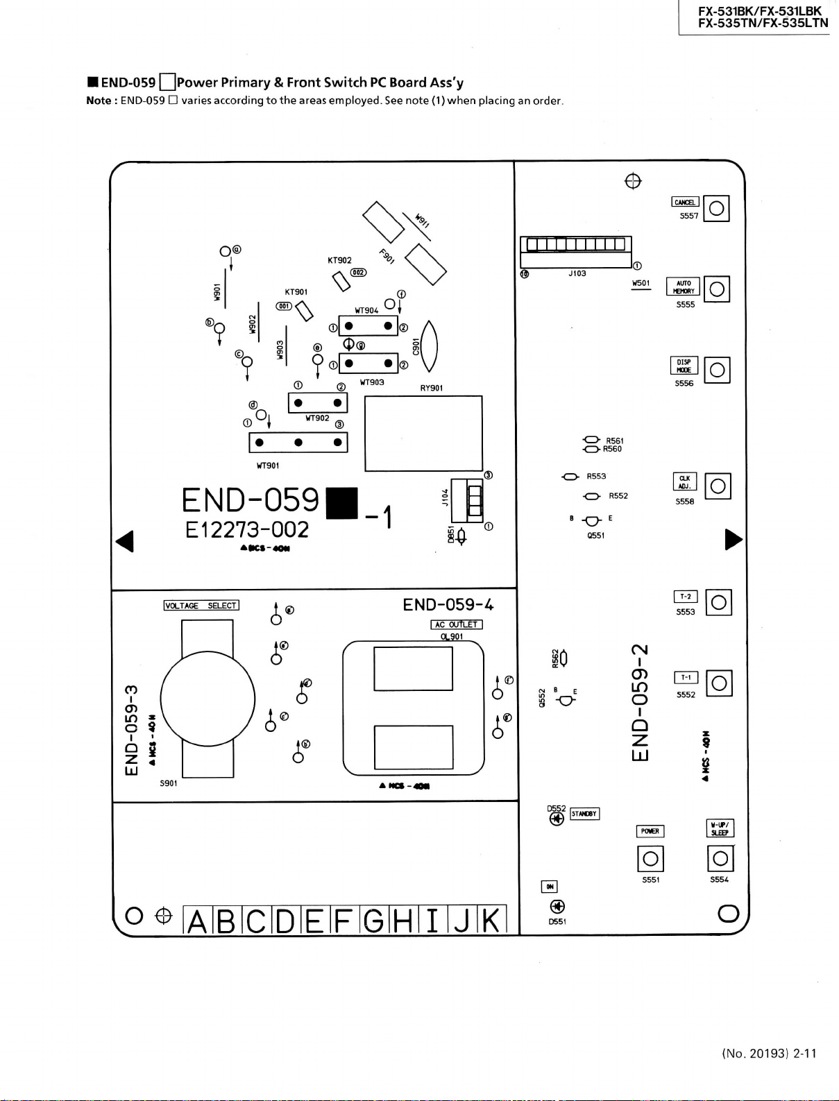
• END-059 LjPowGr Primary & Front Switch PC Board Ass'y
NotG
: El\ID-059 • varies according to the areas employed. See note (1) when placing an order.
0
FX-531BK/FX-531LBK
FX-535TN/FX-535LTN
ICWCELI
O
S557 O S557
O®
?
WT90t
END-059
El
2273-002
AKS-40M
IVOLTAGE
SELECT|
KT902
KT901
®
® @
®
WT903
©
I® A
•
J®
V
END-059-^
I
AC OUTLEfl
OL901
•O R561
•OR560
R553
•CD- R552
-O-'
0551
1®
WSOI
AUTO
HEHonr
S555 O S555
OISP
HCOE
S556
CU
AOJ.
S558
O
O
O
O
O
CO
O 5
S
©
®
Éi
LU
O ^ lAlBiClDIE F G H I J K
10
(N
B E
s -o-
0552 I
® I
C651
I
O)
in
O
Q
z
u
O O
O
S554
O
(No. 20193) 2-11
Page 42

•X-531BK/FX-531LBK
•X-535TN/FX-535LTN
Note(l)
QFX-531LBK
PC Board Ass'y
END-059[D]
END-059[Ë]BS
END-059[F1
Continental Europe (with LW)
the U.K. (witin LW)
West Germany (with LW)
HFX-535TN/FX-535LTN
PC Board Ass'y
END-059[B]
END-059[C]
END-059[D]
END-059[Ë]BS
END-059|T]
Transistors
ITEM
PART
8551
2SC1685<R/S>
Q552
2SA5é'.A(R/S>
Diodes
I
'I'
E \
P
D551
D552
D851
A R T \
SLR-331DU3F
SLH-34VC3F
1SS133
A
NU M HER
Other Countries
Austraria
Continental Europe (with LW)
the U.K. (with LW)
West Germany (with LW)
L'
M B
F,
li
Designated Areas
Designated Areas
D
i-: S C R 1 P T I 0 N AR EA
SILICON MAISUSIIITA
SILICON HATSUSHITA
D
l', S C R I r' T I 0 N
L.E.D.
ROHM
L.E.D.
ROHM
SILICON
ROHM
T'S-
ARRA
Resistors
ITEM
R552
R553
R560
R561
R562
Others
ITEM PART
&
H9Öi
J103
J104
S551
S552
S553
S554
S555
S556
S557
SSS8
S901
A
KT901
KT902
0L901
A
RY9Ö1"
WT901
WT902
WT903
WT9C3
WT9Ö3
WT903
WT904
WT904
WT904
WT904
PART
NUMBER D E S C R
aRD167J-223
aRD167J-103
QRD167J-271
aRDa67J-331
QRD167J-103
NUMBER
E12273-002
E12273-O02
E12273-002
E12273-002BS
E12273-002
E663'.2-00:
EMV7112-010
EMV7112-003
ESPOOOl-018
ESPOOOl-018
ESPOOOl-018
ESPOOOl-018
ESPOOOl-018
ESPOOOl-018
ESPOOOl-018
F.S-CCOl-O'.R
QSR0074-016
E65508-002
E65S08-002
aMC0437-002
•ESKÏDi2-il3
E67764-203
E67764-202
E67764-202
E67764-202
E67764-2d2
E67764-202
E67764-202
E67764-202
E67764-202
E677é4-202
22K
lOK
270
330
lOK
CIBCUIT BOABD
CIRCUIT BOARD
CIBCUIT BOARD
CIRCUIT BOABD
CIRCUIT BOABD
HÖLDËR
CONNECTOR
CONNECTOR
TACT SWITCH
TACT SWITCH
TACT SWITCH
TACT SWITCH
TACT SWITCH
TACT SWITCH
TACT SWITCH
TACT SWITCH
VOLTAGE SELECTOR
TAB
TAB
AC OUTLET
RELAY
WRAPPING TERMINAL
WRAPPING TERMINAL
WRAPPING TERMINAL
WRAPPING TERMINAL
WRAPPÏNG
WRAPPING TERMINAL
WRAPPING TERMINAL
WRAPPING TERMINAL
WRAPPING TERMINAL
H R A P P"i' N 'G' ' f E R M i N A
P
T I 0 N
1/6W
CARBON
1/6W
CARBON
1/6W
CARBON
1/6W
CARBON
1/6W
CARBON
A :iS!A;F:Ë!TlY: IpiAiRTiS:
DESCRIPTION AREA
TERMINAL
L
AREA
B
C
D
EBS
F
B
B
B
C
D
ËBS
F
C
D
EBS
F
Capacitors
I
T
F.
M
A
C901
C901
C901
C901
C901
PART
NUMBER D !•; S C R
QCZ9050-472A
QCZ9050-472A
QC29050-472A
QCZ9050-472ABS
QC29050-',72A
4700PF
4700PF
4700PF
4700PF
4700PF
1'
T I 0 N
CERAMIC
CERAMIC
CERAMIC D
CERAMIC
CERAMIC
A
:^S•^•[':E^T'\•
AREA
iP'A-RiTiS
B
C
EBS
F
A ;!SiA:F:ElTiYi JPiAIRiTS'
2-12 (No. 20193)
Page 43

Accessories List
•
FX-531LBK
Part
A
E30580-1591A
E30580-1591ABS
BT20117
BT20060
BT20066A
E43486-340A
E43486-371A
QZL1008-001
EMZ2001-011
EQB4001-015
EWP302-011
EWP502-001
EWP805-001
E67007-001
EMC0202-001BS
A
QPGA025-03505
QPGA025-03505B
The Marks Designated Areas
LG
West
LBS the U.K. (with
Number
Germany (with
LW) No
LW) LE ,
Part
Name
Instruction
Instruction
Warranty Card
Warranty Card
EEC Agency
Safety Sheet
Sheet
FTZ
Adapter
AM Loop Antenna
Signa!
Built in Antenna
1P Plug Cord
Wire
AC Plug
Envelope
Envelope
Book
Book
Information Sheet
Cord
Antenna
LEF Continental Europe
mark indicates
all
Q'ty
areas.
i
i
i
Description
Excpet
LBS
LG
LBS
LBS
LBS
LBS
LG
Excpet
Excpet
LG
Except
LBS
A:
Areas
LBS
LG
LG
LBS
Safety
FX-531BK/FX-531LBK
FX-535TN/FX-535LTN
Parts
• FX-535TN/FX-535LTN
Part
A
E30580-1591A
E30580-1591ABS
BT20117
BT20060
BT20029C
BT20119
BT20066A
E43486-340A
QZL1008-001
EMZ2001-011
EQB4001-015
EWP302-011
EWP502-001
EWP805-001
E67007-001
EIV1C0202-001BS
E04056
1
E35497-019
QPGA025-03505
QPGA025-03505B
E43486-371A
The Marks Designated Areas
A Australia
U Other Countries
LG
West
Number
LBS
LE ,
Germany (with
Part
Instruction
Instruction
Warranty Card
Warranty Card
Warranty Card
Warranty Card
EEC Agency
Safety Sheet
FTZ
Adapter
AM Loop Antenna
Signa!
Built in Antenna
1P Plug Cord
Wire
AC Plug
Siemens Plug
Caution Sheet
Envelope
Envelope
Sheet
LW) No
Book
Book
Information Sheet
Cord
Antenna
Name
Q'ty
i
for Australia
for New Zealand
i
i
i
220V
1
the U.K. (with
LEF Continental Europe(with
mark indicates all areas.
LW)
Description
LW)
Except
LBS
LG
LBS
A
A
LBS
LBS
LG
LE,
LEF,LBS
Except
LG
LBS
U
U
Except
LBS
LBS
A:
Safety
Areas
LBS
LG
LBS
Parts
(No. 20193) 2-13
Page 44

FX-531BK/FX-531LBK
FX-535TN/FX-535LTN
r
Packing
E406252-001
Sheet
Materials and
Part
Numbers
Accessories
E300196-103 (Except LBS)
E300196-103B (LBS)
Envelope
PK-FX531LBKE
(LE,
LEF, LBS
(E300383-255)
PK-FX531LBKG (LG)
{E300383-256)
PK-FX535TNU (A, U
(E300383-257
PK-FX535LTNE (LE,
(E300383-258)
PK-FX535LTNG (LG)
(E300383-259)
Packing Case
2-14
(No.
20193)
IFX-531LBK
The
Marks
LG West Germany
LBS the U.K.
• FX-535TN/FX-535TLTN
A Australia LBS the U.K.
U Other Countries LE , LEF Continental Euorpe
LG West Germany
(with
LW)
The
(with
Marks
(with
Designated
LW)
Designated
LW) No mark indicates
Areas
LE , LEF Continental Euorpe
No mark indicates
Areas
all
all
areas.
(with
areas.
LW)
E406252-001
Sheet
Page 45

FX-531BK/FX-531LBK
FX-535TN/FX-535LTN
(No.
20193)
(ftk Printed in Japan
^9006[S]
 Loading...