

JVC FS-SD5, FS-SD5UY, FS-SD5U, FS-SD5US, FS-SD7A Instructions Manual
...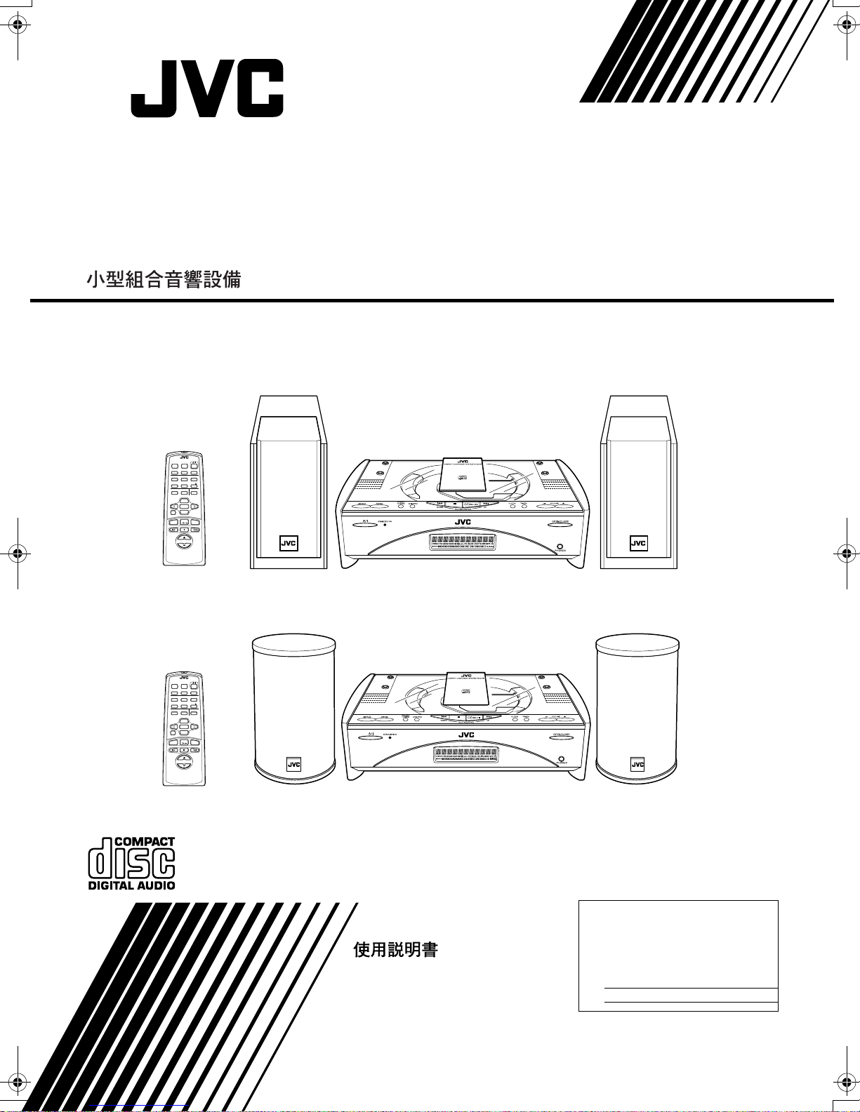
COMPACT COMPONENT SYSTEM
SISTEMAS DE COMPONENTES COMPACTOS
FS-SD5/FS-SD7/FS-SD9
REMOTE CONTROL
DIMMER SLEEP
AUTO
DISPLAY FM MODE
PRESET
PROGRAM
REPEATRANDOM
DOOR
CD
AHB PRO
SLIDE
BASS TREBLE CANCEL
UP
SET
DOWN
FADE MUTING
CD
MD/AUX FM / AM
VOLUME
FS-SD5
REMOTE CONTROL
DIMMER SLEEP
DISPLAY FM MODE
PRESET
PROGRAM
AHB PRO
BASS TREBLE CANCEL
DOWN
FADE MUTING
MD/AUX FM / AM
VOLUME
AUTO
REPEATRANDOM
DOOR
CD
SLIDE
UP
SET
CD
FS-SD7, FS-SD9
INSTRUCTIONS
MANUAL DE INSTRUCCIONES
For Customer Use:
Enter below the Model No. and Serial No.
which are located either on the rear, bottom or side of the cabinet. Retain this
information for future reference.
Model No.
Serial No.
LVT0418-008A
[U/US/UY/UT]
Warnings, Cautions and Others
Avisos, precauciones y otras notas
CAUTION
To reduce the risk of electrical shocks, fire, etc.:
1. Do not remove screws, covers or cabinet.
2. Do not expose this appliance to rain or moisture.
PRECAUCIÓN
Para reducir riesgos de choques eléctricos, incendio, etc.:
1. No extraiga los tornillos, los cubiertas ni la caja.
2. No exponga este aparato a la lluvia o a la humedad.
Caution –– switch!
Disconnect the mains plug to shut the power off completely.
The switch in any position does not disconnect the mains
line. The power can be remote controlled.
Precaución –– Interruptor !
Desconectar el cable de alimentación para desactivar la alimentación totalmente. Cualquier que sea la posición de ajuste
del interruptor , la alimentación no es cortada completamente. La alimentación puede ser controlada remotamente.
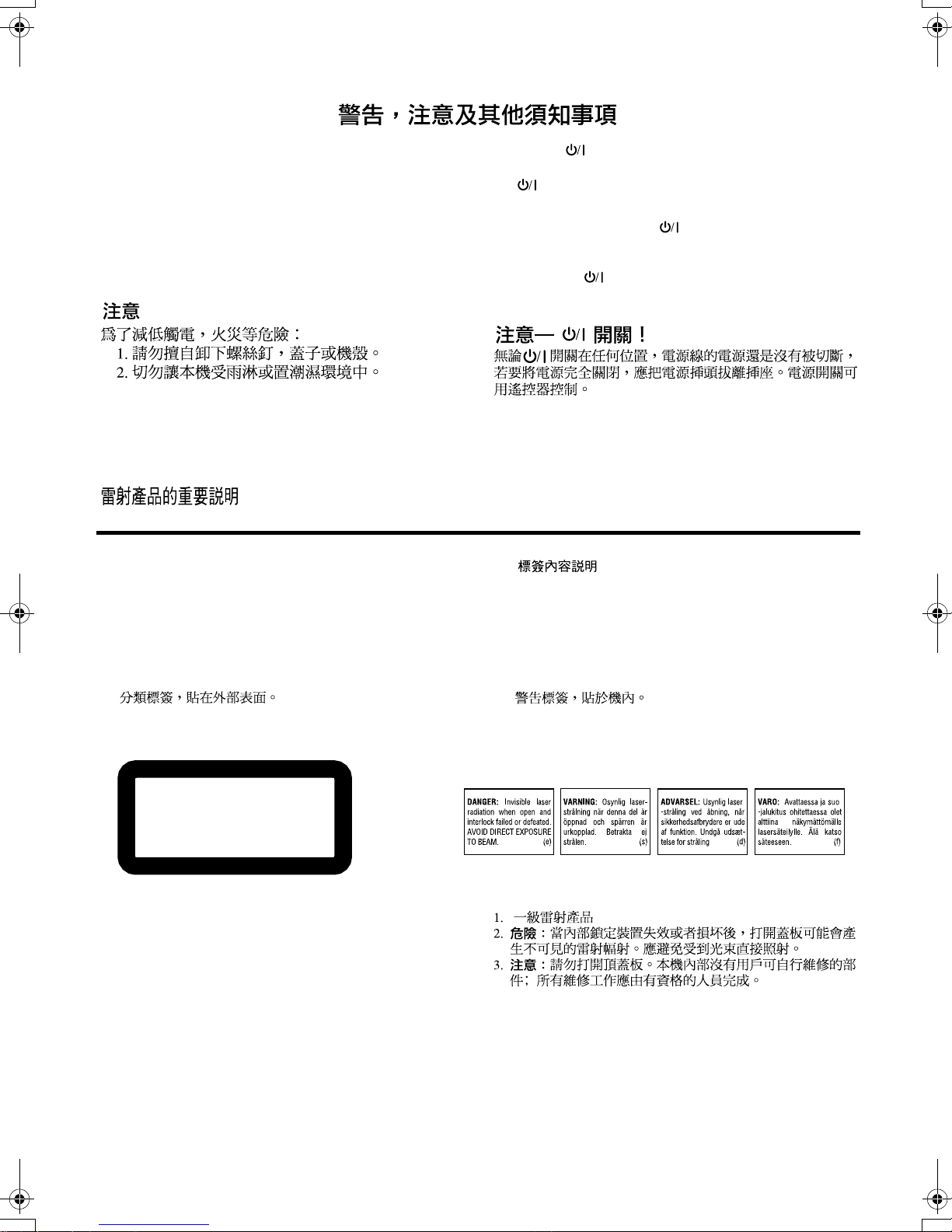
IMPORTANT FOR LASER PRODUCTS / IMPORTANTE PARA PRODUCTOS LÁSER /
REPRODUCTION OF LABELS / REPRODUCCIÓN DE ETIQUETAS /
1 CLASSIFICATION LABEL, PLACED ON EXTERIOR SUR-
FACE
1 ETIQUETA DE CLASIFICACION, PROVISTA SOBRE LA
SUPERFICIE EXTERIOR
1
CLASS 1
LASER PRODUCT
1. CLASS 1 LASER PRODUCT
DANGER:
2.
failed or defeated. Avoid direct exposure to beam.
CAUTION:
3.
serviceable parts inside the Unit; leave all servicing to
qualified service personnel.
1. PRODUCTO LÁSER CLASE 1
PELIGRO:
2.
el contacto directo con el haz.
PRECAUCIÓN:
3.
la unidad no existen piezas reparables por el usuario; deje
todo servicio técnico en manos de personal calificado.
Invisible laser radiation when open and interlock
Do not open the top cover. There are no user
En el interior hay radiación láser invisible. Evite
No abra la tapa superior. En el interior de
2 WARNING LABEL, PLACED INSIDE THE UNIT
2 ETIQUETA DE ADVERTENCIA, PEGADA EN EL INTE-
RIOR DE LA UNIDAD
2
G-1
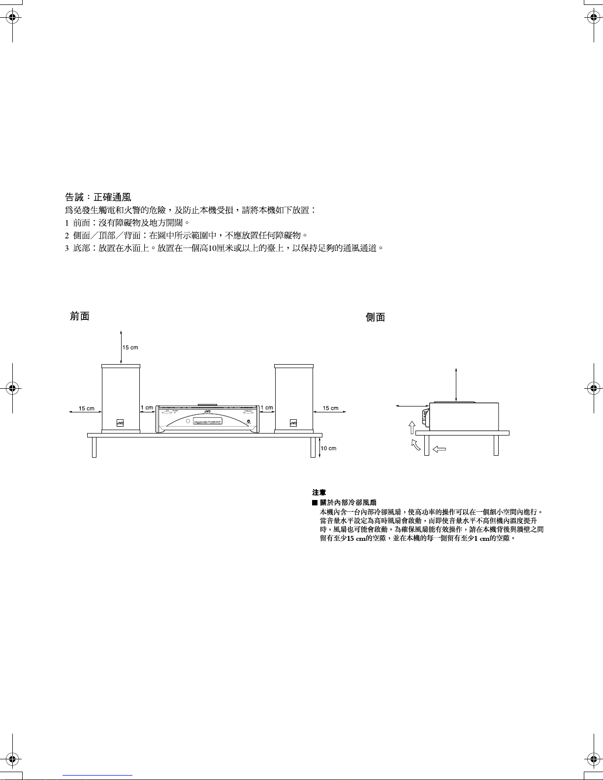
Caution: Proper Ventilation
15 cm
15 cm
To avoid risk of electric shock and fire, and to prevent damage, locate the apparatus as follows:
1 Front: No obstructions and open spacing.
2 Sides/ Top/ Back: No obstructions should be placed in the areas shown by the dimensions below.
3 Bottom: Place on the level surface. Maintain an adequate air path for ventilation by placing on a stand with a height of
10 cm or more.
Precaución: el aparato debe estar bien ventilado
Para evitar posibles riesgos de descargas eléctricas e incendios y prevenir cualquier posible daño, coloque el aparato del modo
siguiente:
1 Parte delantera: No ponga nada delante, deje el espacio libre.
2 Laterales/ parte superior/ No se debería colocar nada en las áreas y las distancias que se detallan a continuación.
parte trasera:
3 Parte inferior: Coloque el aparato sobre una superficie recta. Debe haber buena circulación de aire; para ello,
coloque el aparato sobre una base a una altura mínima de 10 cm.
Front view
Vista frontal
CAUTION
About the Internal Cooling Fan
■■■■
This unit includes an internal cooling fan, so as to allow for highpower operation within a small space.
This fan comes on when the sound level is set high, and may also
come on even at low sound levels if the internal temperature rises. To
ensure effective fan operation, please leave at least 15cm clearance
between the rear of the unit and the wall, and at least 1cm clearance
on each side of the unit.
PRECAUCIÓN
Sobre el ventilador de refrigeración interno
■■■■
El equipo incorpora un ventilador de refrigeración interno para
cuando se utiliza a toda potencia.
El ventilador se pone en marcha cuando sube considerablemente el
volumen o incluso a volúmenes bajos si la temperatura del interior
aumenta. Para que el fun cionamiento del v entilador sea óptimo, debe
dejar al menos 15 cm de distancia entre el equipo y la pared, y como
mínimo 1 cm a cada lado del equipo.
Side view
Vista lateral
G-2
Introduction
Thank you for purchasing the JVC Compact Component System.
We hope it will be a valued addition to your home, giving you years of enjoyment.
Be sure to read this instruction manual carefully before operating your new stereo system.
In it you will find all the information you need to set up and use the system.
English
If you have a query that is not answered by the manual, please contact your dealer.
Features
Here are some of the things that make your System both powerful and simple to use.
■ The controls and operations have been redesigned to make them very easy to use, freeing you to
just enjoy the music.
• With JVC’s COMPU PLAY you can turn on the System and automatically start the Radio or
CD Player with a single touch.
■ The System incorporates Active Hyper Bass PRO circuitry to faithfully reproduce low frequency
sounds.
■ A 45-station preset capability (30 FM and 15 AM ) in addition to auto-seek and manual tuning.
■ CD options that include repeat, random and program play.
■ Timer functions; Daily Timer and Sleep Timer.
■ You can connect various external units, such as an MD recorder.
How This Manual Is Organized
• Basic information that is the same for many different functions - e.g. setting the volume - is given in the section
‘Basic Operations’, and not repeated under each function.
• The names of buttons/controls and display messages are written in all capital letters: e.g. FM/AM, “NO DISC”.
• System functions are written with an initial capital letter only: e.g. Normal Play.
Use the table of contents to look up specific information you require.
We have enjoyed making this manual for you, and hope it serves you in enjoying the many features built into your System.
WARNINGS
• DO NOT PUT ANYTHING ON THE TOP COVER. IF THE SYSTEM IS OPERATED WITH SOMETHING
PUT ON THE TOP COVER, IT WILL BE DAMAGED WHEN YOU TRY TO OPEN THE TOP COVER.
• NEVER REMOVE THE TOP COVER FROM THE UNIT. SERIOUS INJURY MAY OCCUR IF THE SYSTEM IS OPERATED WITHOUT THE TOP COVER.
IMPORTANT CAUTIONS
Installation of the System
1
• Select a place which is level, dry and neither too hot nor too cold. (Between 5°C and 35°C or 41°F and 95°F.)
• Leave sufficient distance between the System and a TV.
• Do not use the System in a place subject to vibrations.
Power cord
2
• Do not handle the power cord with wet hands!
• Some power is always consumed as long as the power cord is connected to the wall outlet.
• When unplugging the System from the wall outlet, always pull the plug, not the power cord.
Malfunctions, etc.
3
• There are no user serviceable parts inside. In case of system failure, unplug the power cord and consult your dealer.
• Do not insert any metallic object into the System.
• Do not insert your hand between the Top Cover and the main body when the Top Cover is being closed.
1

Table of Contents
Introduction........................................................................................................1
Features ......................................................................................................................................1
How This Manual Is Organized.................................................................................................1
WARNINGS ..............................................................................................................................1
IMPORTANT CAUTIONS .......................................................................................................1
Getting Started...................................................................................................3
Accessories.................................................................................................................................3
Set the VOLTAGE SELECTOR Switch....................................................................................3
How To Put Batteries In the Remote Control............................................................................3
Using the Remote Control..........................................................................................................3
Connecting the FM Antenna......................................................................................................4
Connecting the AM Antenna................................................................. .....................................5
Connecting the Speakers........................................ ..................................... ............................ ...6
Attaching the Spacers.......................................................................................................... .......7
Connecting a Subwoofer............................................................................................................7
Connecting External Equipment ........................................................... .....................................7
Connecting an MD Recorder, etc (Digital Output)....................................................................7
Connecting the AC Power Cord.................................................................................................8
COMPU Play................................. .................................... .........................................................8
Automatic Power On..................................................................................................................8
Basic Operations ...............................................................................................9
Turning the Power On and Off...................................................................................................9
Adjusting the Brightness (DIMMER)................................................................. .......................9
Adjusting the Volume ............................................................. ...................................................9
Fade-out Muting (FADE MUTING)........................................................................................ 10
Reinforcing the Bass Sound (AHB PRO)................................................................................10
Tone Control (BASS/TREBLE)...............................................................................................10
Showing the Time (CLOCK/DISPLAY).................................................................................10
Sliding the Top Cover (DOOR SLIDE) ...................................................................................10
Using the Tuner................................................................................................11
Tuning In a Station...................................................................................................................11
Presetting Stations.............................. ..................................... ..................................... ............12
Auto Presetting.................................................... ..................................... ................................12
To Change the FM Reception Mode.......................................................................................12
Using the CD Player.........................................................................................13
To Insert a CD..........................................................................................................................13
To Unload a CD .......................................................................................................................14
Basics of Using the CD Player-Normal Play...........................................................................14
Programming the Playing Order of the Tracks........................................................................14
Random Play............................................................................................................................15
Repeating Tracks......................................................................................................................15
Using External Equipments ............................................................................16
Listening to External Equipment..............................................................................................16
Recording the System’s Source to External Equipment..........................................................16
Using the Timers..............................................................................................17
Setting the Clock......................................................................................................................17
Setting the Daily Timer............................................................................................................17
Setting the SLEEP Timer.........................................................................................................19
Care And Maintenance ....................................................................................20
Troubleshooting...............................................................................................21
Specifications...................................................................................................22
English
2
Getting Started
Accessories
Make sure that you have all of the following items, which are supplied with the System.
English
Power Cord (1)
AM Loop Antenna (1)
Remote Control (1)
Batteries (2)
FM Wire Antenna (1)
Speaker Cords (2)
Spacers (6) (only for FS-SD7 / SD9)
AC Plug Adaptor (except for Argentina) (1)
If any of these items are missing, contact your dealer immediately.
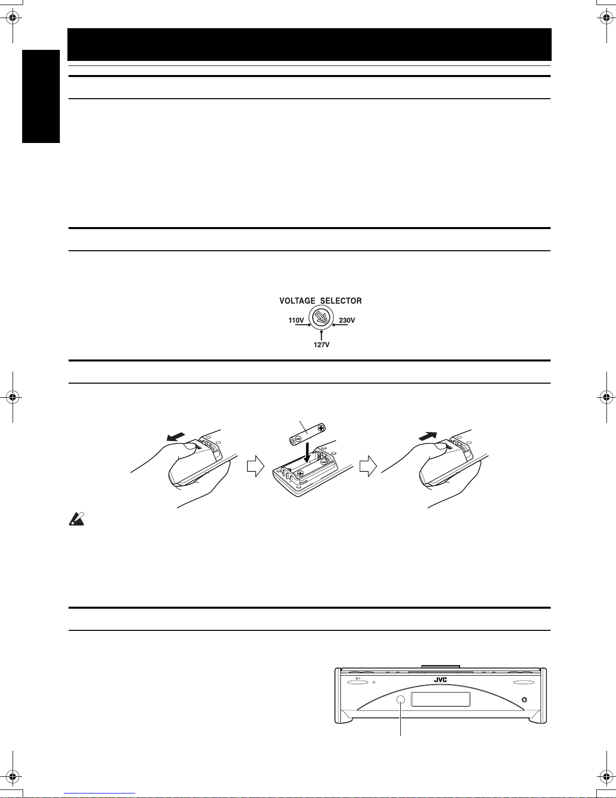
Set the VOLTAGE SELECTOR Switch
To avoid damaging the System, set the voltage before plugging in the System.
Set the correct voltage for your area with the VOLTAGE SELECTOR switch on the back of the Unit. By using a screwdriver,
rotate the VOLTAGE SELECTOR switch so that the arrow mark points the voltage of your area.
How To Put Batteries In the Remote Control
Match the polarity (+ and –) on the batteries with the + and – markings in the battery compartment.
R6P(SUM-3)/AA(15F)
CAUTION:
• Handle batteries properly.
■ To avoid battery leakage or explosion:
• Remove batteries when the Remote Control will not be used for a long time.
• When you need to replace the batteries, replace both batteries at the same time with new ones.
• Do not use an old battery with a new one.
• Do not use different types of batteries together.
Using the Remote Control
The Remote Control makes it easy to use many of the functions of the System from a distance of up to 7m (23 feet) away.
You need to point the Remote Control at the remote sensor on the System’s front panel.
3
STANDBY/ON
Remote sensor
OPEN/CLOSE
PHONES
CAUTION:
• Make all connections before plugging the System into an AC power outlet.
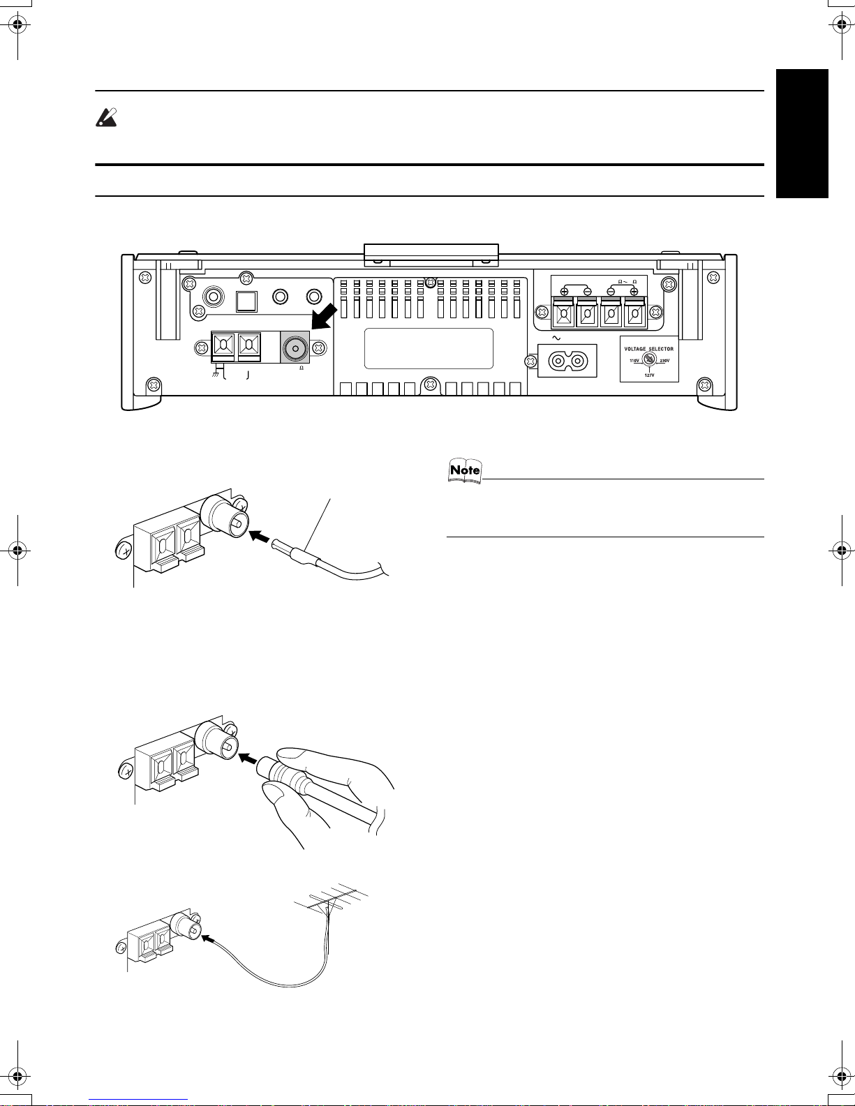
Connecting the FM Antenna
Rear Panel of the Unit
Getting Started
English
SUB WOOFER
CD DIGITAL OUT
AM LOOP
OUT IN
MD
ANTENNA
AM EXT FM(75
COAXIAL
/
AUX
)
Using the Supplied Wire Antenna
FM wire antenna (supplied)
Using the Coaxial Type Connector
(Not Supplied)
A 75-ohm antenna with coaxial type connector (IEC or
DIN45 325) should be connected to the FM 75-ohm COAXIAL terminal.
SPEAKERS IMPEDANCE 4 16
R
AC IN
L
• Before attaching a 75 ohm coaxial lead (the kind with a
round wire going to an outdoor antenna), disconnect the
supplied FM Wire Antenna.
If reception is poor, connect the outdoor antenna.
Coaxial cable
FM outdoor
antenna
(Not supplied)
4

Getting Started
Connecting the AM Antenna
Rear Panel of the Unit
English
SUB WOOFER
CD DIGITAL OUT
AM LOOP
OUT IN
MD
ANTENNA
AM EXT FM(75
COAXIAL
/
AUX
)
AM loop antenna (Supplied)
Attach the AM loop to its base by snapping the tabs on
the loop into the slot in the base.
ANTENNA
AM EXT FM(75
AM LOOP
SPEAKERS IMPEDANCE 4 16
R
AC IN
COAXIAL
L
)
Turn the loop until you have the best reception.
CAUTION:
• To avoid noise, keep antennas away from the System, the connecting cord and the AC power
cord.
5
 Loading...