

Page 1
SERVICE MANUAL
COMPACT COMPONENT SYSTEM
MB21320046
FS-H300, FS-H350
FS-H300
Area suffix
J ---------------------------- U.S.A.
C ------------------------- Canada
FS-H350
Area suffix
C ------------------------- Canada
TABLE OF CONTENTS
1 PRECAUTION. . . . . . . . . . . . . . . . . . . . . . . . . . . . . . . . . . . . . . . . . . . . . . . . . . . . . . . . . . . . . . . . . . . . . . . . . 1-3
2 SPECIFIC SERVICE INSTRUCTIONS . . . . . . . . . . . . . . . . . . . . . . . . . . . . . . . . . . . . . . . . . . . . . . . . . . . . . . 1-6
3 DISASSEMBLY . . . . . . . . . . . . . . . . . . . . . . . . . . . . . . . . . . . . . . . . . . . . . . . . . . . . . . . . . . . . . . . . . . . . . . . 1-7
4 ADJUSTMENT . . . . . . . . . . . . . . . . . . . . . . . . . . . . . . . . . . . . . . . . . . . . . . . . . . . . . . . . . . . . . . . . . . . . . . . 1-18
5 TROUBLESHOOTING . . . . . . . . . . . . . . . . . . . . . . . . . . . . . . . . . . . . . . . . . . . . . . . . . . . . . . . . . . . . . . . . . 1-21
COPYRIGHT © 2004 Victor Company of Japan, Limited
No.MB213
2004/6
Page 2
SPECIFICATION
Amplifier Section-CA-FSH300
Output Power 20 W per channel, min. RMS, driven into 4 Ω at 1 kHz with no more than 10% total
harmonic distortion.
Audio input sensitivity/Impedance (at 1 kHz) AUX:500 mV/50 kΩ
Speakers Impedance 4 Ω - 16 Ω
Tuner FM tuning range 87.5 MHz-108.0 MHz
AM tuning range 530 kHz-1 710 kHz
CD player Dynamic range 85 dB
Signal-to-noise ratio 85 dB
Wow and flutter Immeasurable
Cassette deck Frequency response Normal (type I):100 Hz-10 000 Hz
Wow and flutter 0.35% (WRMS)
General Power requirement AC 120 V , 60 Hz
Power consumption 40 W (at operation) 2 W (on standby)
Dimensions (W/H/D) (approx.) 152 mm × 233 mm × 292 mm (6 in. × 9 3/16 in. × 11 1/2 in.)
Mass (approx.) 3.9 kg (8.6 lbs)
Speaker Section-SP-FSH300
Type Full range, bass-reflex type
Speakers 10 cm cone × 1
Power handling capacity 20 W
Impedance 4 Ω
Frequency range 100 Hz-15 kHz
Dimensions (W/H/D) (approx.) 147 mm × 233 mm × 189 mm (5 13/16 in. × 9 3/16 in. × 7 1/2 in.)
Mass (approx.) 1.9 kg (4.2 lbs) each
Design and specifications are subject to change without notice.
1-2 (No.MB213)
Page 3
SECTION 1
PRECAUTION
1.1 Safety Precautions
(1) This design of this product contains special hardware and
many circuits and components specially for safety purposes. For continued protection, no changes should be made
to the original design unless authorized in writing by the
manufacturer. Replacement parts must be identical to
those used in the original circuits. Services should be performed by qualified personnel only.
(2) Alterations of the design or circuitry of the product should
not be made. Any design alterations of the product should
not be made. Any design alterations or additions will void
the manufacturers warranty and will further relieve the
manufacture of responsibility for personal injury or property
damage resulting therefrom.
(3) Many electrical and mechanical parts in the products have
special safety-related characteristics. These characteristics are often not evident from visual inspection nor can the
protection afforded by them necessarily be obtained by using replacement components rated for higher voltage, wattage, etc. Replacement parts which have these special
safety characteristics are identified in the Parts List of Service Manual. Electrical components having such features
are identified by shading on the schematics and by ( ) on
the Parts List in the Service Manual. The use of a substitute
replacement which does not have the same safety characteristics as the recommended replacement parts shown in
the Parts List of Service Manual may create shock, fire, or
other hazards.
(4) The leads in the products are routed and dressed with ties,
clamps, tubings, barriers and the like to be separated from
live parts, high temperature parts, moving parts and/or
sharp edges for the prevention of electric shock and fire
hazard. When service is required, the original lead routing
and dress should be observed, and it should be confirmed
that they have been returned to normal, after reassembling.
(5) Leakage shock hazard testing
After reassembling the product, always perform an isolation check on the exposed metal parts of the product (antenna terminals, knobs, metal cabinet, screw heads,
headphone jack, control shafts, etc.) to be sure the product
is safe to operate without danger of electrical shock.Do not
use a line isolation transformer during this check.
• Plug the AC line cord directly into the AC outlet. Using a
"Leakage Current Tester", measure the leakage current
from each exposed metal parts of the cabinet, particularly any exposed metal part having a return path to the
chassis, to a known good earth ground. Any leakage current must not exceed 0.5mA AC (r.m.s.).
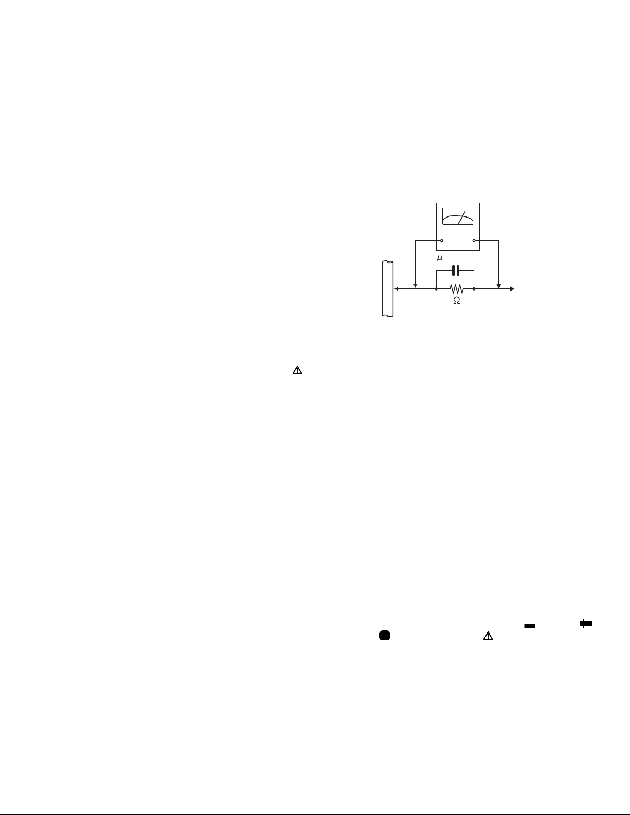
• Alternate check method
Plug the AC line cord directly into the AC outlet. Use an
AC voltmeter having, 1,000Ω per volt or more sensitivity
in the following manner. Connect a 1,500Ω 10W resistor
paralleled by a 0.15µF AC-type capacitor between an ex-
posed metal part and a known good earth ground.
Measure the AC voltage across the resistor with the AC
voltmeter.
Move the resistor connection to each exposed metal
part, particularly any exposed metal part having a return
path to the chassis, and measure the AC voltage across
the resistor. Now, reverse the plug in the AC outlet and
repeat each measurement. Voltage measured any must
not exceed 0.75 V AC (r.m.s.). This corresponds to 0.5
mA AC (r.m.s.).
AC VOLTMETER
(Having 1000
ohms/volts,
or more sensitivity)
0.15 F AC TYPE
Place this
probe on
1500 10W
Good earth ground
1.2 Warning
(1) This equipment has been designed and manufactured to
meet international safety standards.
(2) It is the legal responsibility of the repairer to ensure that
these safety standards are maintained.
(3) Repairs must be made in accordance with the relevant
safety standards.
(4) It is essential that safety critical components are replaced
by approved parts.
(5) If mains voltage selector is provided, check setting for local
voltage.
1.3 Caution
Burrs formed during molding may be left over on some parts
of the chassis.
Therefore, pay attention to such burrs in the case of preforming repair of this system.
1.4 Critical parts for safety
In regard with component parts appearing on the silk-screen
printed side (parts side) of the PWB diagrams, the parts that are
printed over with black such as the resistor ( ), diode ( )
and ICP ( ) or identified by the " " mark nearby are critical
for safety. When replacing them, be sure to use the parts of the
same type and rating as specified by the manufacturer.
(This regulation dose not Except the J and C version)
each exposed
metal part.
(No.MB213)1-3
Page 4
1.5 Preventing static electricity
Electrostatic discharge (ESD), which occurs when static electricity stored in the body, fabric, etc. is discharged, can destroy the laser
diode in the traverse unit (optical pickup). Take care to prevent this when performing repairs.
1.5.1 Grounding to prevent damage by static electricity
Static electricity in the work area can destroy the optical pickup (laser diode) in devices such as laser products.
Be careful to use proper grounding in the area where repairs are being performed.
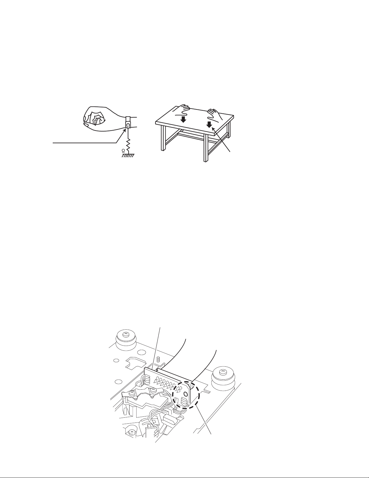
(1) Ground the workbench
Ground the workbench by laying conductive material (such as a conductive sheet) or an iron plate over it before placing the
traverse unit (optical pickup) on it.
(2) Ground yourself
Use an anti-static wrist strap to release any static electricity built up in your body.
(caption)
Anti-static wrist strap
1M
Conductive material
(conductive sheet) or iron palate
(3) Handling the optical pickup
• In order to maintain quality during transport and before installation, both sides of the laser diode on the replacement optical
pickup are shorted. After replacement, return the shorted parts to their original condition.
(Refer to the text.)
• Do not use a tester to check the condition of the laser diode in the optical pickup. The tester's internal power source can easily
destroy the laser diode.
1.6 Handling the traverse unit (optical pickup)
(1) Do not subject the traverse unit (optical pickup) to strong shocks, as it is a sensitive, complex unit.
(2) Cut off the shorted part of the flexible cable using nippers, etc. after replacing the optical pickup. For specific details, refer to the
replacement procedure in the text. Remove the anti-static pin when replacing the traverse unit. Be careful not to take too long a
time when attaching it to the connector.
(3) Handle the flexible cable carefully as it may break when subjected to strong force.
(4) I t is not possible to adjust the semi-fixed resistor that adjusts the laser power. Do not turn it.
1.7 Attention when traverse unit is decomposed
*Please refer to "Disassembly method" in the text for the pickup unit.
• Apply solder to the short land sections before the flexible wire is disconnected from the connecto on the servo board. (If the flexible
wire is disconnected without applying solder, the pickup may be destroyed by static electricity.)
• In the assembly, be sure to remove solder from the short land sections after connecting the flexible wire.
CD pickup board
1-4 (No.MB213)
Short-circuit point
Page 5
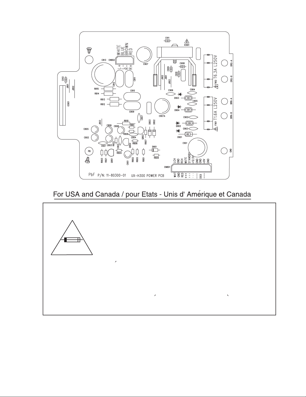
1.8 Importance administering point on the safety
Caution: For continued protection against risk of fire,
replace only with same type 1.6 A/250 V for F901
and 6.3 A/250 V for F902.
This symbol specifies the type of fast operating fuse.
Precaution: Pour la protection continue contre les
risques d'incendie, remplacer uniquement par le
^
meme type: fusible 1.6 A/250 V pour le F901,
6.3 A/250 V pour les F902.
Ce symbole specifie le type de fusible a action rapide.
(No.MB213)1-5
Page 6

SECTION 2
SPECIFIC SERVICE INSTRUCTIONS
This service manual does not describe SPECIFIC SERVICE INSTRUCTIONS.
1-6 (No.MB213)
Page 7
SECTION 3
DISASSEMBLY
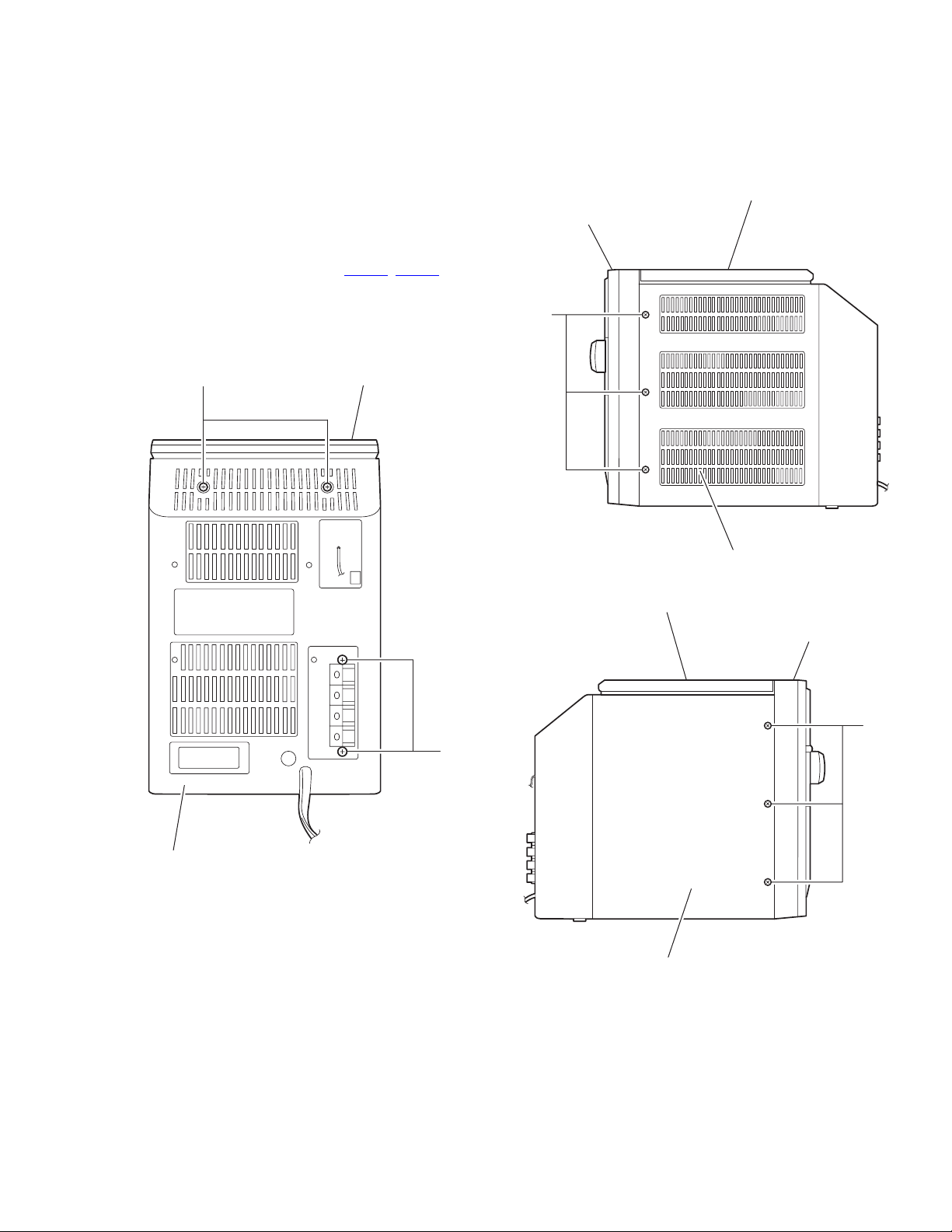
3.1 Removing the front panel assembly (See Fig.1 to 6)
(1) From the back of the body, remove the two screws A and
the two screws B attaching the front panel assembly.
(2) Remove the six screws D on both sides of the body.
(3) Remove the screw E on the bottom of the body.
(4) Move the front panel assembly in the direction of the arrow
and remove. Disconnect connector CN402
main board and disconnect the wire from FM-ANT.
Caution:
When reassembling the front panel assembly, fit the right and
left tabs a to the notch.
, CN801 on the
CD mechanism assembly
Front panelh assembly
D
A
CD mechanism assembly
Rear cover assembly
Fig.2
CD mechanism assembly
Front panelh assembly
D
B
Rear cover assembly
Fig.1
Rear panel assembly
Fig.3
(No.MB213)1-7
Page 8

Front panel assembly
E
Rear panel assembly
Fig.4
CD mechanism assembly
Joint a
Front panel assembly
CD mechanism assembly
FM-ANT
Main board
CN402
CN801
Rear cover assembly
Front panel assembly
Fig.6
Rear cover assembly
Fig.5
1-8 (No.MB213)
Page 9

3.2 Removing the main board (See Fig.7, 8)
• Prior to performing the following procedure, remove the front
panel assembly.
(1) Disconnect the wire from all connectors on the main board.
(2) Disconnect the wire from the two connectors on the cas-
sette mechanism assembly.
(3) Release the three bands attaching the wire to the main
board.
(4) Remove the two screws F from the front panel assembly.
Release the joint b.
Front panel assembly
CD mechanism assembly
Main board
CN203
CN303
CD mechanism assembly
b
CN602
Fig.7
CD mechanism assembly
CN103
CN401
CN301
CN603
F
Front panel assembly
Main board
band
Fig.8
(No.MB213)1-9
Page 10

3.3 Removing the CD mechanism assembly (See Fig.9, 10)
• Prior to performing the following procedure, remove the front
panel assembly and the main board.
(1) Release the four bands setting the wire.
(2) Disconnect the wire from the connector on the CD door
switch and from CN601
mechanism board respectively.
(3) Remove the three screws G attaching the CD mechanism
assembly.
(4) Release the joint d to remove the CD mechanism assem-
bly from the front panel assembly.
, CN603 and CN604 on the CD
Front panel assembly
G
Band
G
Band
CD door switch
CD mechanism assembly
CN601
CN604
Joint d
Joint d
G
CD mechanism board
CN603
Fig.9
CD mechanism assembly
Band
1-10 (No.MB213)
Front panel assembly
Fig.10
Page 11

3.4 Removing the CD mechanism assembly (See Fig.11 to 13)
• Prior to performing the following procedure, remove the front
panel assembly, the main board and the CD mechanism assembly.
Caution:
Before disconnecting the card wire from connector CN607
the CD mechanism board and from CD pickup board, solder
the short-circuit point on the CD pickup board. If you do not follow this instruction, the pickup may be damaged.
(1) Remove the four screws H attaching the CD mechanism
board.
(2) Move the CD mechanism board temporarily and discon-
nect the wire from connector CN606
(3) Solder the short-circuit point on the CD pickup board.
(4) Disconnect the card wire from connector CN607
mechanism board.
Caution:
Make sure to unsolder the short-circuit point after reconnecting
the card wire to the CD pickup board and to connector CN607
on the CD mechanism board.
CD mechanism board
CN606
.
on
on the CD
CD mechanism board
CN606
CN607
Card wire
H
Short-circuit point
CD mechanism assembly
Fig.12
CD pickup board
H
CN607
CD mechanism assembly
Fig.11
Short-circuit point
Unsolder
Fig.13
(No.MB213)1-11
Page 12

3.5 Removing the CD mechanism
A
(See Fig.14)
• Prior to performing the following procedure, remove the front
panel assembly, the main board, the CD mechanism assembly
and the CD mechanism board.
(1) Remove the four screws J attaching the CD mechanism.
J
CD mechanism
3.6 Removing the headphone board/ AUX board
(See Fig.15)
• Prior to performing the following procedure, remove the front
panel assembly, the main board and the CD mechanism assembly.
(1) Remove the screw K attaching the bracket and detach the
headphone board.
(2) Remove the screw M attaching the bracket and detach the
AUX board.
J
M
CD mechanism assembly
Fig.14
Bracket
K
1-12 (No.MB213)
UX board
Head phones board
Front panel assembly
Fig.15
Page 13

3.7 Remove the LCD board (See Fig.16, 17)
• Prior to performing the following procedure, remove the front
panel assembly, the main board and the CD mechanism assembly.
(1) From the front panel, pull out the volume knob and remove
the nut and the washer.
(2) Remove the twelve screws N attaching the LCD board.
Front panel assembly
Volume konb
N
Nat
Washer
Fig.16
N
LCD board
N
N
Fig.17
Front panel assembly
(No.MB213)1-13
Page 14

3.8 Removing the cassette mechanism assembly (See Fig.18, 19)
• Prior to performing the following procedure, remove the front
panel assembly and the main board.
(1) Push ‘PUSH OPEN’ on the front panel to open the cassette
door.
(2) Remove the screw P attaching the bracket of the cassette
mechanism assembly.
(3) Remove the two screws Q and the two screws R attaching
the cassette mechanism assembly.
PUSH OPEN
Cassette door
Front panel assembly
Fig.18
Front panel assembly
1-14 (No.MB213)
R
P
Bracket
R
QQ
Cassette mechaanism assembly
Fig.19
Page 15

3.9 Removing the heat sink/power board (See Fig.20 to 27)
• Prior to performing the following procedure, remove the front
panel assembly.
(1) From the bottom of the rear cover, peel off the tape attach-
ing the wire extending from the power board and remove
the earth plate which is attached with the double-sided
tape.
(2) Remove the four screws T attaching the holder in the pow-
er unit section.
(3) Move the power unit section with the wire from the rear cov-
er temporarily. If necessary, release the band and unsolder
the wire on the power board.
(4) Remove the four screws U and the screw Y attaching the
holder.
(5) Release the wire from the band at ‘e’ and move the holder
in the direction of the arrow to release from the joint f.
(6) Remove the four screws A’ and two screws B’ attaching
the heat sink.
(7) Remove the two screws D’ attaching the power board.
Power unit section
T
Power unit section
T
Rear cover
Ta pe
Fig.20
earth plate
Wire
Rear cover
Rear cover
Power trnsfomer assembly
Fig.21
Ppwer unit section
Fig.22
(No.MB213)1-15
Page 16

Heat sink
U
Holder
A'
U
Power board
Band
Joint f
Power board
Unsolder
Power board
Fig.23
Holder
Y
Band
Heat sink
e
Band
Heat sink
Power board
B'
Fig.25
A'
Heat sink
A'
Fig.26
Unsolder
Band
1-16 (No.MB213)
Bracket
Power board
D'
Power board
Unsolder
Fig.24
Fig.27
Page 17

3.10 Removing the power transformer assembly
r
(See Fig.28, 29)
• Prior to performing the following procedure, remove the front
panel assembly and the power unit section.
(1) Remove the four screws E’ attaching the power transform-
er assembly. The bracket comes off at the bottom of the
rear cover.
(2) Remove the screw F’ attaching the power cord folder.
(3) Remove the screw G’ attaching the power cord.
3.11 Removing the FM antenna board (See Fig.29)
• Prior to performing the following procedure, remove the front
panel assembly and the power unit section.
(1) From the rear cover assembly, remove the screw H’ at-
taching the FM antenna board.
(2) From the FM antenna board, unsolder the FM antenna
wire.
E'
Power trnsfomer assembly
E'
FM antenna board
Power cord folder
Fig.28
H'
Fig.29
F'
G'
Rear cove
Rear cover
Power cord
(No.MB213)1-17
Page 18

SECTION 4
ADJUSTMENT
4.1 Measurement Instruments Required for Adjustment
(1) Low frequency oscillator
This oscillator should have a capacity to output 0dBs to
600Ω at an oscillation frequency of 50Hz-20kHz.
(2) Attenuator impedance : 600Ω
(3) Electronic voltmeter
(4) Distortion meter
(5) Frequency counter
(6) Wow & flutter meter
(7) Test tape
VT703L : Head azimuth
VT712 : Tape speed and running unevenness (3kHz)
VT724 : Reference level (1kHz)
(8) Blank tape
TYPE l : AC-225
TYPE ll : AC-514
(9) Torque gauge : For play and back tension
FWD(TW2111A), REV(TW2121a) and FF/REW(TW2231A)
(10) Test disc: CTS-1000
4.2 Measurement conditons
Power supply voltage AC 230V ~ AC 240V
50Hz/60Hz
Reference output Speaker : 0 dB(2V)/4Ω
Headphone : -10dB(0.245V)/32Ω
Reference frequency and
input level
Measurement output terminal at Speaker
Load resistance 4 Ω
4.2.1 Radio Input signal
AM frequency 1 kHz
AM modulation 30%
FM frequency 1 kHz
FM frequency deviation 22.5kHz
1kHz, AUX : -8 dBs
4.2.2 Tuner section
Voltage applied to tuner +B : DC5.7V
VT : DC 12V
Reference measurement output 26.1mV(0.28V)/3Ω
Input positions AM : Standard loop antenna
FM : TP1 (hot) and TP2 (GND)
4.2.3 Standard measurement position of volume
Function switch to Tape
Beat cut switch to Cut
Super Bass/Active hyper Bass to OFF
Bass Treble to Center
Adjustment of main volume to reference output VOL : 0.775V
Precautions for measurement
(1) Apply 30pF and 33kΩ to the IF sweeper output side and
0.082µ F and 100kΩ in series to the sweeper input side.
(2) The IF sweeper output level should be made as low as
possible within the adjustable range.
(3) Since the IF sweeper is a fixed device, there is no need
to adjust this sweeper.
(4) Since a ceramic oscillator is used, there is no need to
perform any MIX adjustment.
(5) Since a fixed coil is used, there is no need to adjust the
FM tracking.
(6) The input and output earth systems are separated. In
case of simultaneously measuring the voltage in both of
the input and output systems with an electronic voltmeter
for two channels, therefore, the earth should be connected particularly carefully.
(7) In the case of BTL connection amp., the minus terminal
of speaker is not for earthing. Therefore, be sure not to
connect any other earth terminal to this terminal. This
system is of an BTL system.
(8) For connecting a dummy resistor when measuring the
output, use the wire with a greater code size.
(9) Whenever any mixed tape is used, use the band pass fil-
ter (DV-12).
1-18 (No.MB213)
Page 19

4.2.4 Cassette amplifier section
Item Measuring condition Check and adjustment procedure Standard value Adjusting part
Head azimuth
adjustment
Test tape:VT703L
Signal output
terminal:PHONES
(with 32 ohm load)
Tape speed and
wow / flutter check
and adjustment
Test tape:VT712
Signal output
terminal:PHONES
(with 32 ohm load)
REC and PB
frequency response
adjustment
Test tape:VT703L
Signal input FM 22.5
DEV 60dB with
Emphasis
Signal output
terminal:PHONES
(with 32 ohm load)
4.2.5 Tuner section
Item Measuring condition Check and adjustment procedure Standard value Adjusting part
1.Play back the test tape VT703L.
2.Adjust the head azimuth adjusting screw so that
the phase difference between the L and R
channels is minimized at an output level that is
within +/- 2 dB of the maxmum ooutput level.
After this adjustment, lock the kead azimuth
adjusting screw with screw sealant to cover more
than a half of the screw head.
When the head azimuth is maladjusted, correct it
3.
with the head azimuth adjusting screw.
1.Playback the test tape VT712 by the end position.
Connect a frequency counter and check that it
2.
reads between 2940 and 3090 Hz. If not, adjust
the frequency with the motor semifixed resistor.
Check that the wow/flutter is within 0.38%
3.
(unweighted)
At TUNER, set the BAND to the FM position, and
record the reference 1 kHz signal and 10kHz
signal alternately repeatedly. While playing back
the recorded signal differ from that of the 1 kHz
signal by within 0 ( +3 to -6) dB.
Output level:
Within +/-2 dB of
maximum output
level
Phase difference
L and R
channels:Minimum
2940 to 3090 Hz
within 0.38 %
(unweighted)
Level difference
between REC and
PB:Within 0
(+3 to -6) dB.
Head azimuth
adjusting
screw (to be
used only
after head
replacement)
Tape speed:
Motor semifixed
resistor
AM IF adjustment Signal input:
Loop antenna
Signal output:
IC101 pin (16)
AM tracking
adjustment
Signal input:
Loop antenna
PHONES (with 32
ohm load)
4.2.6 Location of adjusting parts
1. Set the intermediate frequency sweep generator
to AM 450 kHz.
Adjust the T103 for maxmum and center output.
2.
1. Set the TUNER at 530 kHz adjust T102 until the
test pin of VD103 voltage at 1.5 V +/- 0.1 V.
2.
Set the TUNER at 1710 kHz, check the pin of
VD103 voltage at 9.0V +/- 0.5V.
Set the TUNER and S/G at 600kHz, adjust T101
3.
for maximum output.
Set the TUNER and S/G at 1400 kHz, adjust
4.
VC101 for maximum output.
Repeat the above steps 3 and 4.
5.
Main board assemblyCassette mechanism section
R226
R225
L203
J201
BIAS FREQUENCY
IC202
L101
T103
IC101
VD101
T102
T103
T102
T101
VD103
VC102
T101
VD103
VC101
VD102
Tape Speed Adj.
-
+
CASSETTE MOTOR
(No.MB213)1-19
Page 20

4.3 Wiring connection
P/N:11-80300-02
CD board
CN601
CN604
P/N:20-41092-56
P/N:11-80300-06
LED board
CN607
P/N:20-41102-38
CN602
CN603
CN605
P/N:20-41062-80
2
0
9
P/N:25-61080-80
231549
P/N:98-00010-80
CD MECH
BOTTOM SIDE
P/N:11-80300-10
FM ANT board
P/N:29-00300-00
FM ANT
P/N:20-42041-82
CN101
P/N:31-90080-80
CN801
CN401
AM LOOP ANT
FM ANT
P/N:11-80300-04
P/N:29-00300-00
P/N:23-04910-80
CON401
PHONE board
P/N:20-42041-82
CN603
CN402
P/N:11-80300-05
AUX board
CON301
902
Color codes are shown below
1 --- BROWN
2 --- RED
3 --- ORANGE
4 --- YELLOW
5 --- GREEN
P/N:94-34309-00
CASS LOGIC DECK
BOTTOM SIDE
P/N:20-61063-81
6 --- BLUE
7 --- VIOLET
8 --- GRAY
9 --- WHITE
0 --- BLACK
LEFT SPEAKER
P/N:20-41092-57
P/N:25-23050-82
CNM705
CN708
CN704
P/N:11-80300-03
CPU & KEY board
CN701
CN707
P/N:20-42021-80
P/N:20-41021-80
CN706
P/N:20-41072-80
CN703
CD702
P/N:30-00300-00L
P/N:78-00004-85
P/N:11-80300-08
MAIN board
P/N:20-41082-81
90
P/N:20-61031-22
CN201
CN103
P/N:20-41082-48
P/N:20-61031-21
CN301
0
2
0
4
9
9
0
CN602
P/N:15-80300-00
TRANSFORMER
CN202
CN303
CN203
RIGHT SPEAKER
P/N:20-42041-81
P/N:20-61010-80
1
1
3
3
2169
209
CN801
P/N:11-80300-01
POWER board
1-20 (No.MB213)
00
CN802
Page 21

SECTION 5
TROUBLESHOOTING
Circuit Symptom Cause and Remedy
General
AM
No sound
No sound,weak sound
(Low sensitivity)
Defective earphone jack:
Replace the earphone jack.
Defect in IC801
Check voltages. Replace if necessary.
Defect in IC301
Check voltages. Replace if necessary.
Defect in IF T103:
Check resistance, voltage, and current. Replace as needed.
Defect AM antenna coil T101 or oscilloscope coil T102:
Replace if necessary.
Intermediate Frequency tuning faulty:
Readjust (see "Alignment and Adjustment").
RF tracking faulty:
Readjust (see "Alignment and Adjustment").
Defective IC101:
Check voltages. Replace if necessary.
Defective IC102:
Check voltages. Replace if necessary.
Poor contact in antenna circuit:
Check resistance and resolder.
FM No sound, weak sound
Tape Dirty capstan or head:
CD Cannot read the table of
(Low sensitivity)
No sound/recording,
unsteady tape sound,
weak sound
content.
no sound
Defective band selector switch:
Replace or repair the switch.
Defective IC101:
Check voltages. Replace if necessary.
Defective IC102:
Check voltages. Replace if necessary.
Intermediate Frequency tuning faulty:
Readjust (see "Alignment and Adjustment").
Poor contact in FM antenna circuit:
Resolder or repair as required.
Clean the capstan or head with alcohol.
Irregular cassette tape winding:
Replace tape.
Defective IC201:
Check voltage. Replace if necessary.
Cassette erasure prevention tabs broken out:
Replace tape or cover tab openings with adhesive tape.
Disc is dirty:
Wipe clean with a soft cloth.
Disc is seriously warped:
Use a new disc.
Moisture has formed inside the CD deck:
Wait about 20 to 30 minutes.
Defective IC601:
Check voltages. Replace if necessary.
Defective IC602:
Check voltages. Replace if necessary.
Defective IC603:
Check voltages. Replace if necessary.
Defective IC604:
Check voltages. Replace if necessary.
Defective IC606:
Check voltages. Replace if necessary.
Defective IC607:
Check voltages. Replace if necessary.
Defective IC608:
Check voltages. Replace if necessary.
Defective IC609:
Check voltages. Replace if necessary.
Defect in the CD pickup mechanism:
Replace as required.
(No.MB213)1-21
Page 22

Victor Company of Japan, Limited
AV & MULTIMEDIA COMPANY AUDIO/VIDEO SYSTEMS CATEGORY 10-1,1chome,Ohwatari-machi,Maebashi-city,371-8543,Japan
(No.MB213)
Printed in Japan
WPC
 Loading...