

Page 1
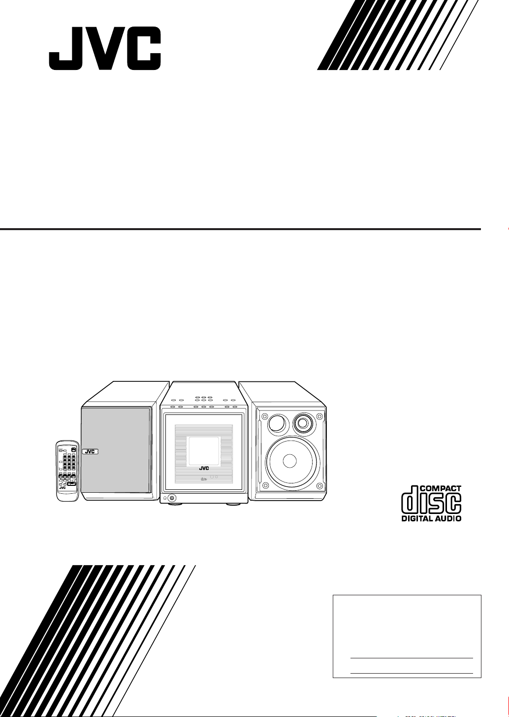
COMPACT COMPONENT SYSTEM
FS-A52 — Consists of CA-FSA52 and SP-UXA52
COLOR
DIMMER
STANDBY/ON
CLOCK
SLEEP
FM MODE
/TIMER
123
456
DISPLAY
789
+
10
0
10
SET
CANCEL
REV.MODE
REPEAT
PLAY MODE
CD
TAPE
AUX/MD
FM/AM
BEEP
SOUND
AHB
VOLUME
MODE
PRO
RM-SFSA52J
COMPACT COMPONENT SYSTEM FS-A52
PHONES
STANDBY/ON
COMPACT
DIGITAL AUDIO
INSTRUCTIONS
For Customer Use:
Enter below the Model No. and Serial
No. which are located either on the rear,
bottom or side of the cabinet. Retain this
information for future reference.
Model No.
Serial No.
GVT0071-001B
[J]
Page 2
Warnings, Cautions and Others
Mises en garde, précautions et indications diverses
CAUTION
RISK OF ELECTRIC SHOCK
DO NOT OPEN
CAUTION: TO REDUCE THE RISK OF ELECTRIC SHOCK,
DO NOT REMOVE COVER (OR BACK).
NO USER SERVICEABLE PARTS INSIDE.
REFER SERVICING TO QUALIFIED SERVICE PERSONNEL.
The lightning flash with arrowhead symbol,
within an equilateral triangle is intended to
alert the user to the presence of uninsulated
"dangerous voltage" within the product's
enclosure that may be of sufficient
magnitude to constitute a risk of electric
shock to persons.
The exclamation point within an equilateral
triangle is intended to alert the user to the
presence of important operating and
maintenance (servicing) instructions in the
literature accompanying the appliance.
WARNING: TO REDUCE THE RISK OF FIRE
OR ELECTRIC SHOCK, DO NOT EXPOSE
THIS APPLIANCE TO RAIN OR MOISTURE.
CAUTION
To reduce the risk of electrical shocks, fire, etc.:
1. Do not remove screws, covers or cabinet.
2. Do not expose this appliance to rain or
moisture.
ATTENTION
Afin d’éviter tout risque d’électrocution, d’incendie, etc.:
1. Ne pas enlever les vis ni les panneaux et ne
pas ouvrir le coffret de l’appareil.
2. Ne pas exposer l’appareil à la pluie ni à
l’humidité.
Caution –– STANDBY/ON button!
Disconnect the mains plug to shut the power off
completely (the STANDBY/ON lamp goes off).
The STANDBY/ON button in any position
does not disconnect the mains line.
• When the unit is on standby, the STANDBY/ON
lamp lights red.
• When the unit is turned on, the STANDBY/ON
lamp lights green.
The power can be remote controlled.
Attention –– Commutateur STANDBY/ON!
Déconnectez la prise d’alimentation secteur pour
mettre l’appareil complètement hors tension (le
témoin STANDBY/ON s’éteint).
L’interrupteur STANDBY/ON, sur n’importe
quelle position, ne peut pas déconnecter
l’appareil du secteur.
• Quand l’appareil est en mode de veille, le témoin
STANDBY/ON est allumé en rouge.
• Quand l’appareil est sous tension, le témoin
STANDBY/ON est allumé en vert.
L’alimentation peut être télécommandée.
1. CLASS 1 LASER PRODUCT
2. DANGER: Invisible laser radiation when open and
interlock failed or defeated. Avoid direct exposure to
beam.
3. CAUTION: Do not open the top cover. There are no
user serviceable parts inside the Unit; leave all
servicing to qualified service personnel.
1. PRODUIT LASER CLASSE 1
2. ATTENTION: Radiation laser invisible quand
l’appareil est ouvert ou que le verrouillage est en
panne ou désactivé. Eviter une exposition directe
au rayon.
3. ATTENTION: Ne pas ouvrir le couvercle du dessus.
Il n’y a aucune pièce utilisable à l’intérieur. Laisser
à un personnel qualifié le soin de réparer votre
appareil.
– G-1 –
Page 3

For U.S.A.
This equipment has been tested and found to comply with the limits
for a Class B digital device, pursuant to part 15 of the FCC Rules.
These limits are designed to provide reasonable protection against
harmful interference in a residential installation.
This equipment generates, uses and can radiate radio frequency
energy and, if not installed and used in accordance with the
instructions, may cause harmful interference to radio
communications. However, there is no guarantee that interference
will not occur in a particular installation. If this equipment does cause
harmful interference to radio or television reception, which can be
determined by turning the equipment off and on, the user is
encouraged to try to correct the interference by one or more of the
following measures:
Reorient or relocate the receiving antenna.
Increase the separation between the equipment and receiver.
Connect the equipment into an outlet on a circuit different from that
to which the receiver is connected.
Consult the dealer or an experienced radio/TV technician for help.
For Canada/pour le Canada
CAUTION: TO PREVENT ELECTRIC SHOCK, MATCH
WIDE BLADE OF PLUG TO WIDE SLOT, FULLY INSERT.
ATTENTION: POUR EVITER LES CHOCS
ELECTRIQUES, INTRODUIRE LA LAME LA PLUS
LARGE DE LA FICHE DANS LA BORNE
CORRESPONDANTE DE LA PRISE ET POUSSER
JUSQUAU FOND.
For Canada/pour le Canada
THIS DIGITAL APPARATUS DOES NOT EXCEED THE
CLASS B LIMITS FOR RADIO NOISE EMISSIONS
FROM DIGITAL APPARATUS AS SET OUT IN THE
INTERFERENCE-CAUSING EQUIPMENT STANDARD
ENTITLED “DIGITAL APPARATUS”, ICES-003 OF THE
DEPARTMENT OF COMMUNICATIONS.
CET APPAREIL NUMERIQUE RESPECTE LES LIMITES
DE BRUITS RADIOELECTRIQUES APPLICABLES AUX
APPAREILS NUMERIQUES DE CLASSE B
PRESCRITES DANS LA NORME SUR LE MATERIEL
BROUILLEUR: “APPAREILS NUMERIQUES”, NMB-003
EDICTEE PAR LE MINISTRE DES COMMUNICATIONS.
– G-2 –
Page 4
Introduction
We would like to thank you for purchasing one of our JVC products.
Before operating this unit, read this manual carefully and thoroughly to
obtain the best possible performance from your unit, and retain this manual
for future reference.
About This Manual
Power sources
This manual is organized as follows:
• This manual mainly explains playback using the
remote control, and the other operations such as
recording operations using the buttons on the unit.
You can use the buttons both on the remote control
and on the unit for the same operations if they have
the same or similar names (or marks), unless
mentioned otherwise.
• Basic and common information that is the same for
many functions is grouped in one place, and is not
repeated in each procedure. For instance, we do not
repeat the information about turning on/off the unit,
setting the volume, changing the sound effects, and
others, which are explained in the section “Basic and
Common Operations” on pages 10 – 13.
• The following marks are used in this manual:
• When unplugging the unit from the wall outlet, always
pull the plug, not the AC power cord.
DO NOT handle the AC power cord with wet
hands.
Moisture condensation
Moisture may condense on the lens inside the unit in the
following cases:
• After starting heating in the room
• In a damp room
• If the unit is brought directly from a cold to a warm place
Should this occur, the unit may malfunction. In this case,
leave the unit turned on for a few hours until the moisture
evaporates, unplug the AC power cord, then plug it in
again.
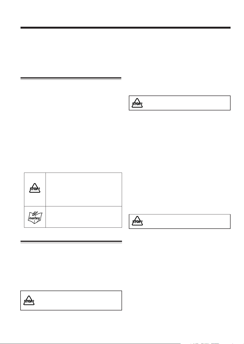
Gives you warning and caution to prevent
from damage or risk of fire/electric shock.
Furthermore, gives you information which
is not good for obtaining the best possible
performance from the unit.
Gives you information and hints you had
better know.
Precautions
Installation
• Install in a place which is level, dry and neither too hot
nor too cold—between 5˚C (41˚F) and 35˚C (95˚F).
• Install the unit in a location with adequate ventilation to
prevent internal heat buildup in the unit.
• Leave sufficient distance between the unit and the TV.
• Keep the speakers away from the TV to avoid
interference with TV.
DO NOT install the unit in a location near heat
sources, or in a place subject to direct sunlight,
excessive dust or vibration.
Others
• Should any metallic object or liquid fall into the unit,
unplug the AC power cord and consult your dealer before
operating any further.
• If you are not going to operate the unit for an extended
period of time, unplug the AC power cord from the wall
outlet.
DO NOT disassemble the unit since there are no
user serviceable parts inside.
If anything goes wrong, unplug the AC power cord and
consult your dealer.
– 1 –
Page 5

Contents
Location of the Buttons .................................. 3
Main Unit ............................................................... 3
Remote Control ...................................................... 5
Getting Started................................................ 6
Unpacking .............................................................. 6
Putting the Batteries into the Remote Control ......... 6
Connecting Antennas .............................................. 7
Connecting Speakers ............................................... 8
Connecting Other Equipment .................................. 9
Basic and Common Operations ................... 10
Turning On the Power ........................................... 11
Selecting the Sources and Starting Play ................ 11
Adjusting the Volume ............................................ 12
Turning On/Off the Key-touch Tone ...................... 12
Reinforcing the Bass Sound .................................. 12
Selecting the Sound Modes ................................... 12
Setting the Display Illumination ............................ 13
Listening to FM and AM Broadcasts .......... 14
Tuning in a Station ................................................ 15
Presetting Stations ................................................ 15
Tuning in a Preset Station ..................................... 16
Playing Back a CD ........................................ 17
Precautions on CD Playback ................................. 18
Playing Back the Entire CD—Normal Play .......... 18
Basic CD Operations ............................................ 19
Programing the Playing Order of the Tracks
—Program Play .............................................. 20
Playing at Random—Random Play ....................... 21
Repeating Tracks—Repeat Play ............................ 21
Playing Back a Tape ..................................... 22
Playing Back a Tape ............................................. 23
Using External Equipment .......................... 24
Listening to External Equipment ........................... 25
Recording from This Unit
to External Equipment .................................... 25
Recording on Tapes ...................................... 26
Before You Start Recording................................... 27
Recording FM/AM Broadcasts ............................. 28
Recording CD—CD Synchronized Recording ...... 28
Recording External Equipment ............................. 29
Using the Timers ........................................... 30
Setting the Clock ................................................... 31
Using Recording Timer ......................................... 31
Using Daily Timer ................................................ 32
Using Sleep Timer ................................................ 34
Timer Priority ....................................................... 34
Maintenance .................................................. 35
Troubleshooting ............................................ 36
Specifications................................................. 36
– 2 –
Page 6

Location of the Buttons
Become familiar with the buttons on your unit.
Main Unit
Top view
Front view
r
t
1
2
3
4
5
PBC REC
DAILY SOUND AHB
PRO
ST MONO
COMPACT COMPONENT SYSTEM FS-A52
COMPACT
DIGITAL AUDIO
STANDBY/ON
AUX/MD
F M / A M
AHB PRO
STANDBY/ON COLOR
open/close
select
MODE
C D open/close
6
SLEEP
REC
start
7
Display—indicators
o
;
a
i
8
PBC REC
TAPE
VOLUME
g
DAILY
ST MONO
e
w
q
p
9
f
d
SOUND AHB
PRO
GROUP
s
y
PHONES
u
– 3 –
Page 7

See pages in the parentheses for details.
Continued
Main unit
1 FM/AM button (11, 15)
• Pressing this button also turns on the unit.
2 COLOR button (9, 13)
3
4 CD open/close 0 button (18 – 20)
5 CD # ¥ 8 (play/pause) button (11, 18, 28)
6 MODE select and REC start buttons (28, 29)
7 Multi operation buttons
8 SLEEP button (34)
9 TAPE @ # (play) button (11, 23, 28, 29)
p TAPE open/close 0 button (23)
q VOLUME + / – buttons (12, 25)
w AHB (Active Hyper Bass) PRO button (12, 25)
e AUX/MD button (11, 25, 29)
r Electronic swing panel
t Display
y PHONES (
u Remote sensor
i STANDBY/ON lamp (11)
STANDBY/ON button (11)
• Pressing this button also turns on the unit.
• Pressing this button also turns on the unit.
• 4 (reverse skip), 7 (stop), and ¢ (forward skip)
• Pressing this button also turns on the unit.
• Pressing this button also turns on the unit.
• Pressing this button also turns on the unit.
• Shows the source name and some indicators, etc.
) jack—stereo mini-type (12)
Display—indicators
o Timer mode indicators (31 – 34)
(Timer), DAILY (Daily Timer), and REC
•
(Recording Timer)
; CD indicator
• Lights when CD is in the disc tray.
a Tuner indicator
• Lights when the tuner is selected as the source.
s Tape indicator
• Lights when a cassette is in the cassette loading slot.
d AHB (Active Hyper Bass) PRO indicator (12)
f SOUND indicator (12)
g ST (stereo) and MONO indicators (15)
COMPACT COMPONENT SYSTEM FS-A52
PHONES
STANDBY/ON
COMPACT
DIGITAL AUDIO
When using the remote control, point it at the remote
sensor on the electronic swing panel.
– 4 –
STANDBY/ON
EP
LE
DIMMER
S
E
OD
M
COLOR
FM
CK
O
L
R
C
E
IM
/T
23
1
456
LAY
SP
89
DI
7
10
+
0
10
PLAY MODE
SET
REPEAT
DE
D
O
M
•
V.M
E
UX
R
A
CANCEL
TAPE
M
FM/A
BEEP
CD
E
LUM
O
V
B
H
A
O
PR
D
N
OU
S
E
J
D
2
O
5
M
A
S
F
-S
M
R
Page 8
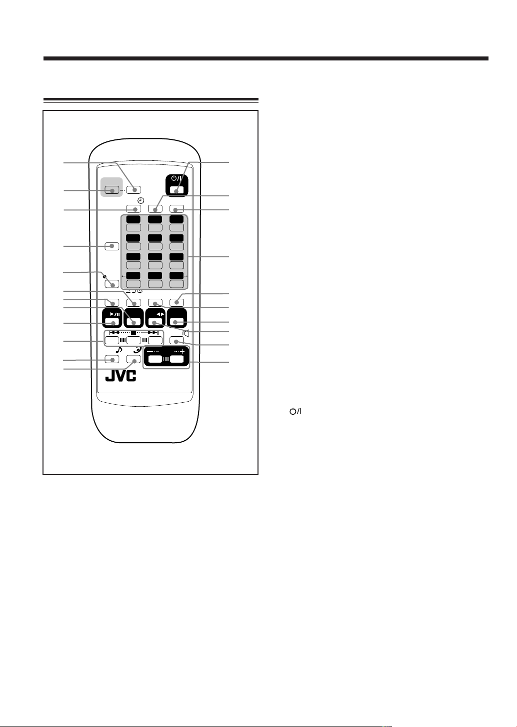
Remote Control
1
2
3
4
5
6
7
8
9
p
q
w
COLOR
DISPLAY
SET
CANCEL
CD
SOUND
MODE
DIMMER
CLOCK
/TIMER
123
456
789
10
REV.MODE
FM/AM
AHB
PRO
FM MODE
0
REPEAT
TAPE
VOLUME
RM-SFSA52J
STANDBY/ON
SLEEP
+
PLAY MODE
AUX/MD
BEEP
Remote control
1 DIMMER button (13, 31)
2 COLOR button (9, 13)
3 CLOCK/TIMER button (31 – 33)
4 DISPLAY button (16, 19, 23, 28, 29)
5 SET button (13, 15, 31 – 34)
s
a
;
o
10
i
u
y
t
r
e
6 REV. (reverse) MODE button (23)
7 CANCEL button (20, 31, 32)
8 FM/AM button (11, 15, 16)
• Pressing this button also turns on the unit.
9 CD 3 ¥ 8 (play/pause) button (11, 18 – 21)
• Pressing this button also turns on the unit.
p Multi operation buttons
• 4 (reverse skip), 7 (stop), and ¢ (forward skip)
q SOUND MODE button (12, 25)
w AHB (Active Hyper Bass) PRO button (12, 25)
e VOLUME + / – buttons (12, 25)
r BEEP button (12)
t TAPE 2 3 button (11, 23)
• Pressing this button also turns on the unit.
y AUX/MD button (11, 25)
• Pressing this button also turns on the unit.
u REPEAT button (21)
i PLAY MODE button (20, 21)
o Number buttons
• 0, 1 – 10, +10 buttons
• + / = buttons (13)
; SLEEP button (34)
a FM MODE button (15)
STANDBY/ON button (11, 32, 33)
s
– 5 –
Page 9
Getting Started
Continued
Unpacking
Make sure that you have all the following items.
The number in parentheses indicates the quantity of the
pieces supplied.
• FM antenna (1)
• AM loop antenna (1)
• AC power cord (1)
• Remote control (1)
• Batteries (2)
If anything is missing, consult your dealer immediately.
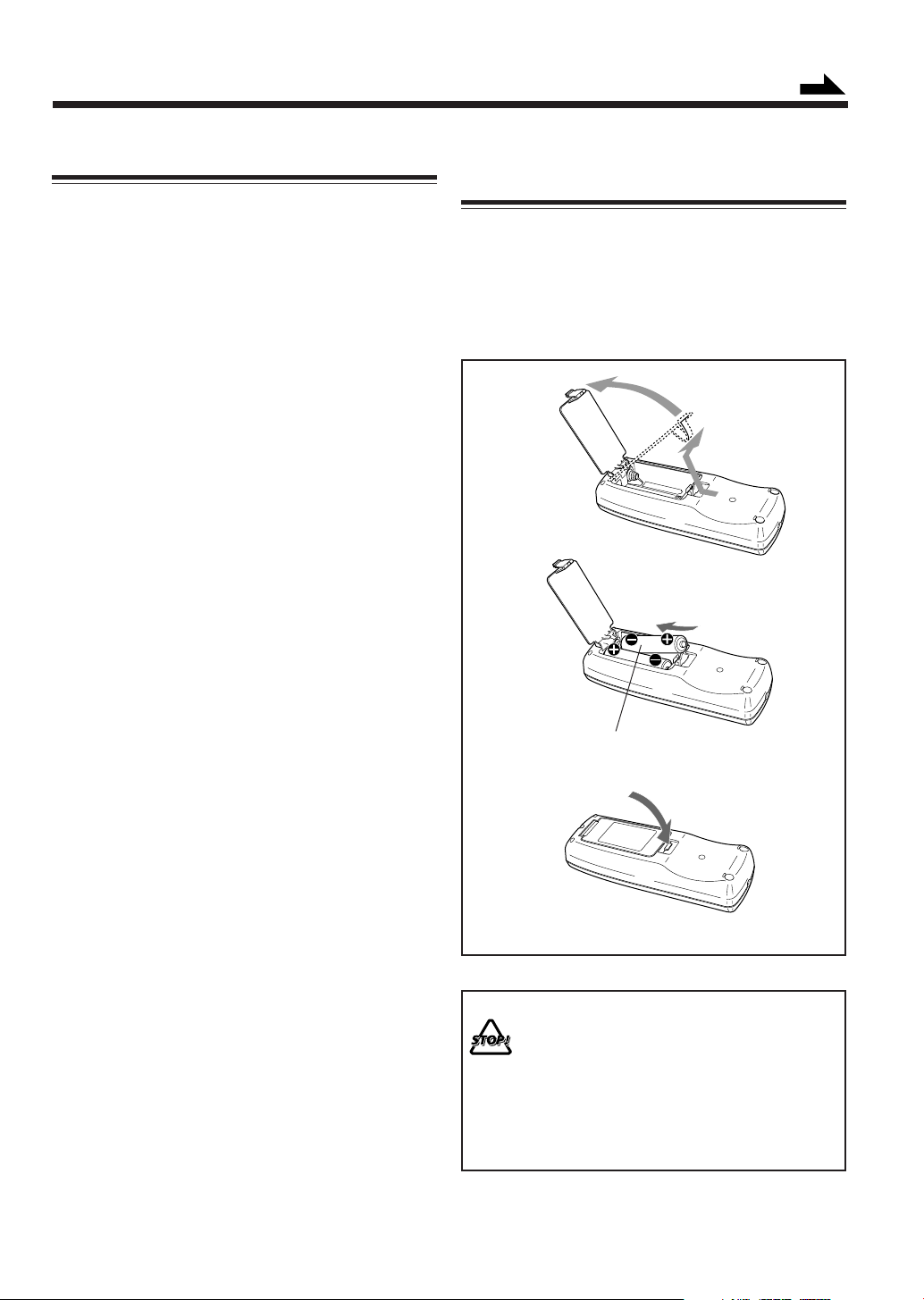
Putting the Batteries into the Remote
Control
Insert the batteries—R6P(SUM-3)/AA(15F)—into the
remote control, by matching the polarity (+ and –) on the
batteries with the + and – marking on the battery
compartment.
When the remote control can no longer operate the unit,
replace both batteries at the same time.
1
2
R6P(SUM-3)/AA(15F)
3
• DO NOT use an old battery together with a new
one.
• DO NOT use different types of batteries together.
• DO NOT expose batteries to heat or flame.
• DO NOT leave the batteries in the battery
compartment when you are not going to use the
remote control for an extended period of time.
Otherwise, it will be damaged from battery
leakage.
– 6 –
Page 10
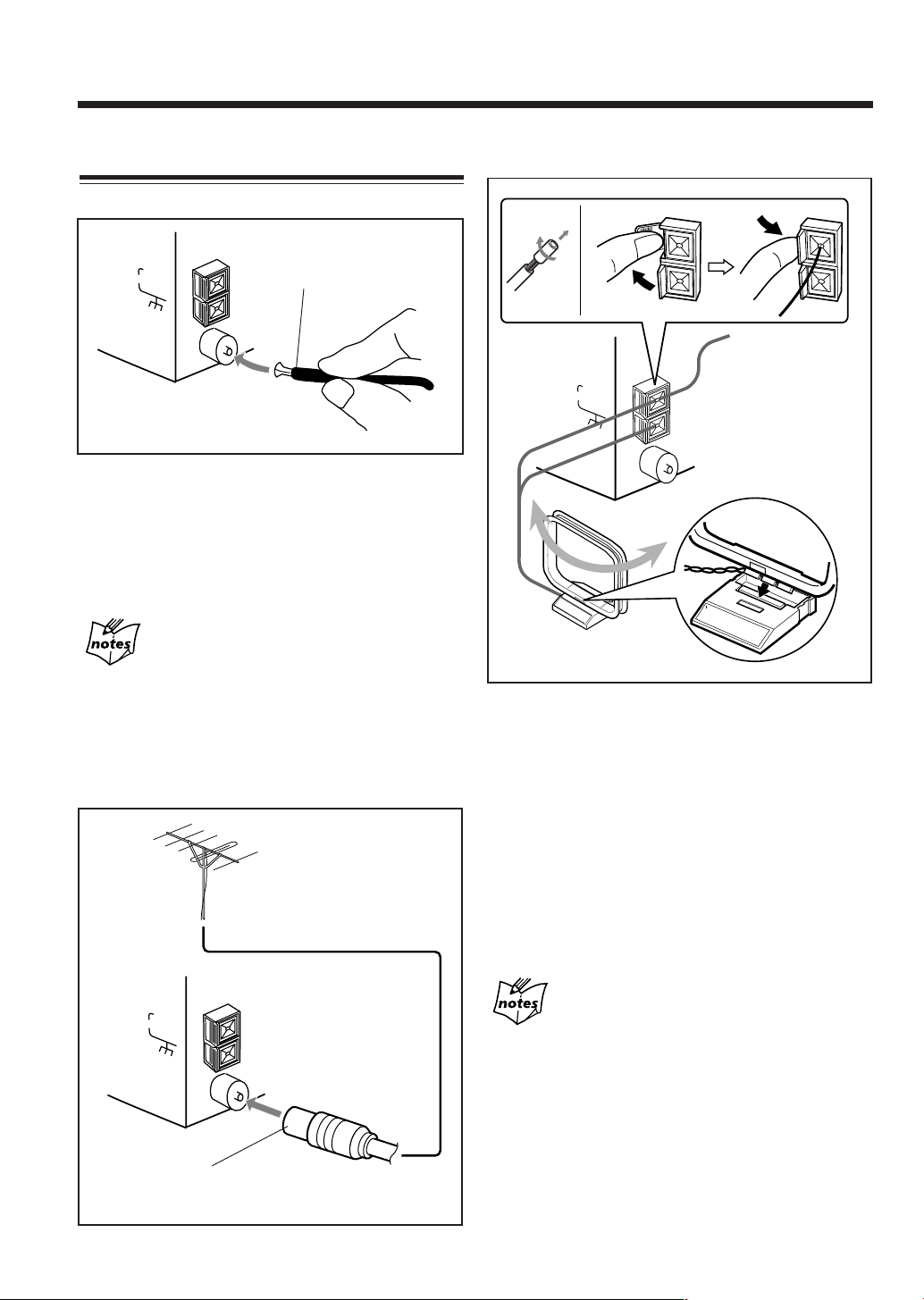
Connecting Antennas
AM antenna
FM antenna
ANTENNA
AM EXT
AM LOOP
FM(75Ω)
COAXIAL
1
Attach the FM antenna to the FM (75 Ω) COAXIAL
FM antenna (supplied)
terminal.
2
Extend the FM antenna.
3
Fasten it up in the position which gives you the best
reception.
About the supplied FM antenna
The FM antenna supplied with this unit can be used as temporary
measure. If reception is poor, you can connect an outdoor FM
antenna.
To connect an outdoor FM antenna
Before connecting it, disconnect the supplied FM antenna.
Outdoor FM antenna
(not supplied)
ANTENNA
AM EXT
AM LOOP
FM(75Ω)
COAXIAL
1
2
ANTENNA
AM EXT
AM LOOP
FM(75
Ω)
COAXIAL
Vinyl-covered wire
(not supplied)
3
AM loop antenna
(supplied)
1
If cords are covered with insulation, twist the core
of the cord at the end of each cord, then remove the
insulation.
2
Connect the AM loop antenna to the AM LOOP
terminals as illustrated.
3
Turn the AM loop antenna until you have the best
reception.
To connect an outdoor AM antenna
When reception is poor, connect a single vinyl-covered
wire to the AM EXT terminal and extend it horizontally.
The AM loop antenna must remain connected.
• Make sure the antenna conductors do not touch any other
• Keep the antennas away from metallic parts of the unit,
For better reception of both FM and AM
terminals and connecting cords.
connecting cords, and the AC power cord.
A 75 Ω antenna with coaxial type
connector should be used.
– 7 –
Page 11
Continued
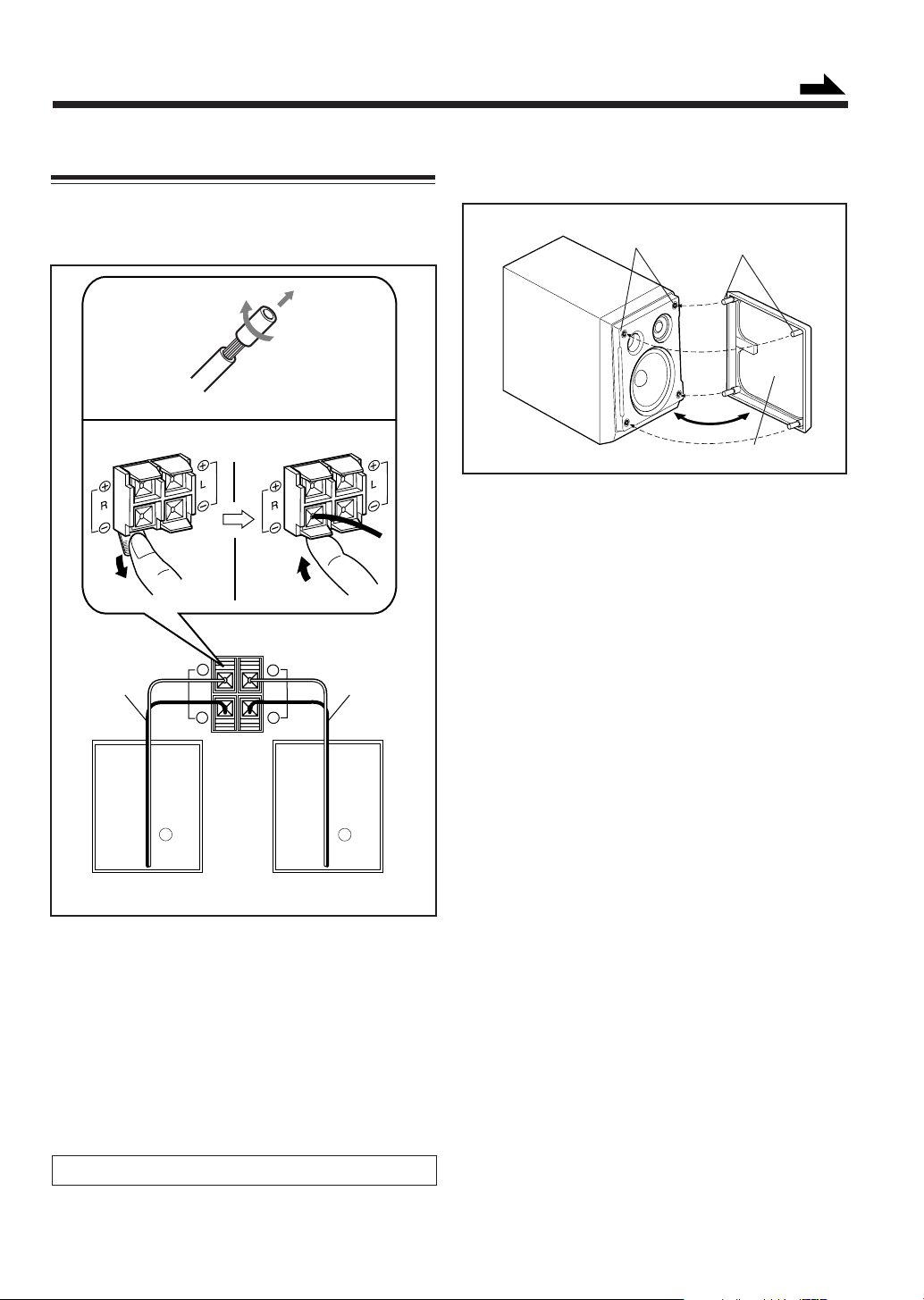
Connecting Speakers
To connect speakers
You can connect the speakers by following the procedure
below:
1
Speaker cord
Speaker terminals
SPEAKER IMPEDANCE
MIN 4Ω
+
RL
+
––
3,42
Speaker cord
To remove the speaker grilles
The speaker grilles are removable.
Holes
To remove the speaker grille, insert your fingers at the top
of the speaker grille, then pull towards you. Do the same at
the bottom.
To attach the speaker grille, put the projections of the
speaker grille into the holes of the speaker.
Projections
Speaker grille
RL
Rear of the right
speaker
1
If cords are covered with insulation, twist the core
of the cord at the end of each cord, then remove the
insulation.
2
Open the speaker terminal.
3
Insert the end of the speaker cord to the terminal.
Match the polarity: White cord to (+) terminal and
black cord to (–) terminal.
4
Close the speaker terminal on the rear of the unit.
Use only speakers with the speaker impedance—4 Ω to16 Ω.
Rear of the left
speaker
– 8 –
Page 12
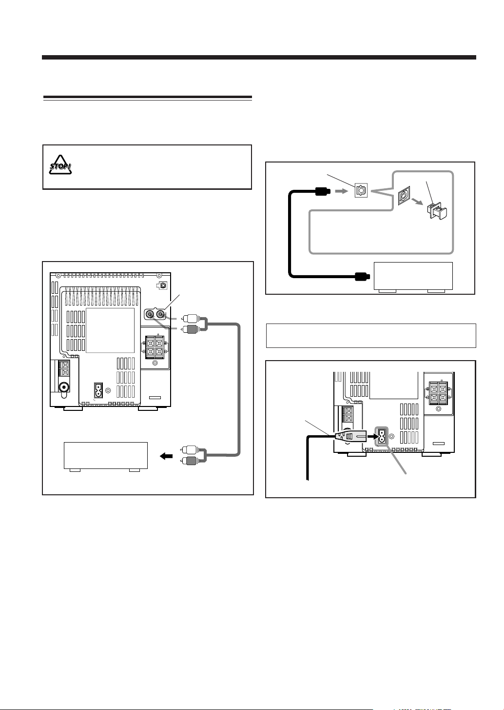
Connecting Other Equipment
You can connect both of the analog and digital equipment.
When you connect and use the equipment, refer also to its
manual supplied.
• DO NOT connect other equipment while the
power is on.
• DO NOT plug in any equipment until all
connections are complete.
To connect analog audio equipment
Be sure that the plugs of the audio cords and the jacks on
the rear of the unit are color-coded: White plugs and jacks
are for left audio signals, and red ones for right audio
signals.
LINE IN
RL
(AUX)
To connect audio equipment with an optical digital
input terminal
You can record CD sound onto the connected digital
equipment.
Connect an optical digital cord (not supplied) between the
optical digital input terminal on the other equipment and
the OPTICAL DIGITAL OUT terminal.
OPTICAL DIGITAL OUT
terminal
Before connecting the other equipment,
remove the protective cap from the
terminal.
Protective cap
Audio equipment with
an optical digital input
NOW, you can plug the AC power cord.
SPEAKER IMPEDANCE
MIN 4
R
L
AC IN
Analog audio
equipment
To output
For playing the other equipment through this unit,
connect between the audio output jacks on the other
equipment and the LINE IN (AUX) jacks by using an audio
cord (not supplied.)
IMPORTANT: Be sure to check all connections to be done
before plugging the AC power cord into a wall outlet.
SPEAKER IMPEDANCE
MIN 4
R
L
AC power cord
(supplied)
AC IN
1
2
To a wall outlet
To the AC IN terminal
When connecting the AC power cord into a wall outlet, the
unit automatically starts the display illumination.
To stop and cancel the display demonstration, press
COLOR during display illumination—while the unit is
turned off (on standby.)
To start the display illumination manually, press
COLOR again while the unit is turned off (on standby.)
– 9 –
Page 13

Basic and Common Operations
The buttons emphasized in the illustration below are used and explained in this section (pages 11 to 13.)
Remote control
Continued
Main unit (Top view)
COLOR DIMMER
SET
STANDBY/ON
COLOR
MODE
COLOR
DISPLAY
SET
CANCEL
CD
SOUND
MODE
F M / A M
select
DIMMER
CLOCK
/TIMER
FM MODE
STANDBY/ON
SLEEP
123
456
789
0
10
REV.MODE
REPEAT
PLAY MODE
TAPE
AUX/MD
REC
VOLUME
RM-SFSA52J
start
AUX/MD
BEEP
AHB PRO
SLEEP
FM/AM
AHB
PRO
STANDBY/ON
0
+
FM/AM
10
TAPE
AUX/MD
10
+
10
CD
BEEP
SOUND
VOLUME
MODE
AHB
PRO
VOLUME
Main unit (Front view)
open/close
C D open/close
COMPACT
DIGITAL AUDIO
PHONES
TAPE
STANDBY/ON
– 10 –
Page 14

Turning On the Power
Selecting the Sources and Starting Play
When you press the play buttons (CD 3 / 8, TAPE 2 3)
for a particular source or FM/AM and AUX/MD, the unit
automatically turns on (and starts playback if the source is
ready.)
To turn on the unit without playing, press
STANDBY/ON.
The STANDBY/ON lamp on the electronic swing panel
lights green.
To turn off the unit (on standby), press
STANDBY/ON again.
The STANDBY/ON lamp on the electronic swing panel
lights red.
•“AM12:00” appears on the display until you set the
built-in clock. After setting the clock, the clock time will
appear on the display while the unit is turned off (on
standby.)
• A little power is always consumed even while the unit is
on standby.
To set the built-in clock, see page 31.
To switch off the power supply completely, unplug the
AC power cord from the AC outlet.
When you unplug the AC power cord or if a power
failure occurs
The clock setting, the tuner preset stations and other settings will
be erased.
To select the tuner, press FM/AM.
The unit automatically turns on (when the unit is on
standby) and the last selected station is tuned in.
Each time you press FM/AM, the band alternates between
FM and AM.
• For more detailed operations, see pages 14 to 16.
To select the CD player, press CD 3 / 8.
The unit automatically turns on (when the unit is on
standby), and “CD” appears on the display. Play will start if
a CD is on the disc tray. (“NO DISC” will appear on the
display if a CD is not loaded.)
To stop playback, press 7.
• For more detailed operations, see pages 17 to 21.
To select the cassette deck, press TAPE 2 3.
The unit automatically turns on (when the unit is on
standby), and “TAPE” appears on the display. Play will
start if a cassette is in the cassette loading slot. (“NO
TAPE” will appear on the display if a cassette is not in the
cassette loading slot.)
To stop playback, press 7.
• For more detailed operations, see pages 22 and 23.
To select external equipment, press AUX/MD.
The unit automatically turns on (when the unit is on
standby), and “AUX” appears on the display.
• For more detailed operations, see pages 24 and 25.
• For operating the external equipment, see the manuals
supplied with them.
– 11 –
Page 15

Continued
Adjusting the Volume
You can adjust the volume level while the unit is turned on.
The volume level has no effect on recording.
To increase the volume, press VOLUME +.
To decrease the volume, press VOLUME –.
(Maximum)
(Minimum)
The volume level meter appears on the display.
• The volume level can be adjusted in 41 steps (VOL MIN,
VOL 1 – VOL 39, and VOL MAX.)
• When pressing and holding the button, you can change
the volume level continuously.
For private listening
Connect the headphones to the PHONES jack. No sound comes
out of the speakers. Be sure to turn down the volume before
connecting or putting on the headphones.
DO NOT turn off (on standby) the unit with the
volume set to an extremely high level; otherwise, the
sudden blast of sound can damage your hearing,
speakers and/or headphones when you turn on the
unit or start playing any source.
REMEMBER you cannot adjust the volume level
while the unit is on standby mode.
Turning On/Off the Key-touch Tone
If you do not want the key-touch tone to beep each time
you press buttons, you can deactivate it while the unit is
turned on.
On the remote control ONLY:
Press BEEP.
• Each time you press the button, the key-touch tone turns
on (BEEP ON) and off (BEEP OFF) alternately:
BEEP ON BEEP OFF
Reinforcing the Bass Sound
The richness and fullness of the bass sound is clearly
maintained regardless of how low you set the volume—
Active Hyper Bass PRO. You can select the bass effect
levels while the unit is turned on. The AHB PRO can be
applied only to playback sounds, and cannot be used for
recording.
To get the effect, press AHB PRO.
The AHB PRO indicator lights on the display.
• Each time you press the button, the effect changes as
follows:
AHB 1 AHB 2
AHB OFF
(Canceled)
AHB 1: Bass sound is clearly heard even in the low
volume.
AHB 2: Bass sound is more effective than AHB 1.
AHB OFF: Cancels the AHB PRO.
The AHB PRO indicator goes off from the
display.
To check the AHB PRO setting currently selected, press
AHB PRO once while the AHB PRO indicator is lit.
Selecting the Sound Modes
You can select one of the 4 preset sound modes while the
unit is turned on. The sound modes can be applied only to
playback sounds, and cannot be used for recording.
On the remote control ONLY:
To select the sound modes, press SOUND MODE
repeatedly until the sound mode you want appears on the
display.
The SOUND indicator also lights on the display.
• Each time you press the button, the sound mode changes
as follows:
ROCK POP
FLAT
(Canceled)
ROCK: Boosts low and high frequency.
Good for acoustic music.
POP: Good for vocal music or voice.
CLASSIC: Good for classical music.
JAZZ: Good for jazz music.
FLAT: Cancels the sound mode.
The SOUND indicator goes off from the
display.
To check the sound mode currently selected, press
SOUND MODE once while the SOUND indicator is lit.
CLASSIC
JAZZ
– 12 –
Page 16

Setting the Display Illumination
You can change the color and brightness of the display
illumination.
To select the color pattern
You can select the color pattern by your preference.
While the unit is turned on, press COLOR repeatedly
until the color pattern you want appears on the display.
• Each time you press the button, the color pattern changes
as follows:
COLOR
RANDOM
COLOR
GRADATION
To adjust and register the color
You can adjust the color by changing the tone, whiteness,
brightness, and register into COLOR 1 to 7.
• There is a time limit in doing the following steps. If the
setting is canceled before you finish, start from step
again.
On the remote control ONLY:
1
Press COLOR repeatedly until the color number
(COLOR 1 to 7) you want to adjust appears on the
display.
The adjustment bars appear on the display.
1
COLOR 1
– COLOR 7
COLOR RANDOM: Changes the illumination color
randomly every 2 seconds.
COLOR GRADATION:
Changes the illumination color
gradually.
TODAY’S COLOR #* DAILY:
Changes the illumination color
every day. You can select which
color to start with. (See “To select
TODAY’S COLOR” to the right
column.)
* The color number of TODAY’S COLOR is selected
from COLOR 1 – 7.
COLOR 1 – 7: You can adjust and register the
color from COLOR 1 to 7. (See
“To adjust and register the color”
to the right column.)
• If you press COLOR while the unit is turned off, the
display illumination will start (see page 9.)
TODAY’S
COLOR #
DAILY
*
2
Adjust the tone, whiteness, and brightness.
1) Press = or + to select the level you want and
press SET.
• Each time you press SET, the adjustment items
change.
• The tone can be adjusted in 14 patterns. The
whiteness can be adjusted in 3 levels and the
brightness can be adjusted in 2 levels.
2) Repeat 1) to adjust “WHITENESS” and
“BRIGHTNESS.”
• If the whiteness is set to the right end, the tone
you adjusted will be no longer valid.
To select “TODAY’S COLOR”
The illumination color changes automatically each time the
built-in clock becomes “AM12:00.”
• There is a time limit in doing the following steps. If the
setting is canceled before you finish, start from step
again.
On the remote control ONLY:
1
Press COLOR repeatedly until “TODAY’S
COLOR” appears on the display.
2
Press = or + to select the color number (COLOR 1
to 7.)
1
More on the display illumination
• The colors shown on the display cannot always be reproduced
precisely. Due to the circumstances (room temperature, etc.)
where the unit is used, colors may vary slightly.
• When you change the color of the display, the display may seem
to move back and forth; this is a characteristic of this unit and is
not a malfunction.
• When a strong light strikes the display, the display happens to
become dark, but this is not a malfunction.
– 13 –
To dim the display
This function can be used only while the unit is turned on.
On the remote control ONLY:
To dim the display, press DIMMER.
To brighten the display, press DIMMER again.
• Pressing COLOR also brightens the display.
Page 17

Listening to FM and AM Broadcasts
The buttons emphasized in the illustration below are used and explained in this section (pages 15 to 16.)
Remote control
FM MODE
COLOR
DISPLAY
SET
FM/AM
DISPLAY
SET
CANCEL
CD
SOUND
MODE
DIMMER
CLOCK
/TIMER
10
REV.MODE
FM/AM
AHB
PRO
STANDBY/ON
SLEEP
FM MODE
123
456
789
+
10
0
REPEAT
PLAY MODE
TAPE
AUX/MD
BEEP
VOLUME
123
456
789
10
0
Continued
+
10
Main unit (Top view)
STANDBY/ON
open/close
RM-SFSA52J
F M / A M
AUX/MD
AHB PRO
COLOR
MODE
select
C D open/close
SLEEP
REC
start
VOLUME
TAPE
– 14 –
Page 18

Tuning in a Station
Presetting Stations
1
Press FM/AM repeatedly to select “FM” or “AM.”
The unit automatically turns on with the last selected
station.
• Each time you press the button, the band alternates
between FM and AM.
2
Press and hold ¢ or 4 until the station
frequencies start changing on the display.
• ¢ : to increase the frequencies.
• 4 : to decrease the frequencies.
The unit starts searching stations and stops when a
station of sufficient signal strength is tuned in.
Ex. An FM station is tuned in.
• If an FM program is broadcast in stereo, the ST
(stereo) indicator lights on the display.
To stop during searching, press ¢ or 4.
The frequency changes step by step.
When you press ¢ or 4 repeatedly
You can preset 30 FM and 15 AM stations manually.
In some cases, test frequencies have been already memorized
for the tuner since the factory examined the tuner preset
function before shipment. This is not a malfunction. You can
preset the stations you want into memory by following the
presetting method.
• There is a time limit in doing the following steps. If the
setting is canceled before you finish, start from step
again.
On the remote control ONLY:
1
Tune in a station you want to preset.
• See “Tuning in a Station” to the left column.
2
Press SET.
The preset number starts flashing as follows:
• When you select an FM station in step
• When you select an AM station in step
2
1
1
To change the FM reception mode
When an FM stereo broadcast is noisy or hard to receive,
you can change the FM reception mode to improve the
reception.
On the remote control ONLY:
Press FM MODE so that the MONO indicator lights on
the display.
• Each time you press the button, the MONO indicator
lights and goes off alternately.
When the MONO indicator is lit:
Reception improves though stereo effect is lost.
When the MONO indicator is not lit:
You can hear stereo sound when a program is
broadcast in stereo.
The ST (stereo) indicator lights while receiving
the FM stereo broadcast (only when the reception
is good.)
In addition, static noise between stations will be
erased while tuning.
Preset No. 1 always appears at first.
3
Press the number buttons to select a preset number.
Ex. For preset number 5, press 5.
For preset number 15, press +10, then 5.
For preset number 20, press +10, then 10.
For preset number 30, press +10, +10, then 10.
• You can also select the preset number by pressing
¢ or 4.
4
Press SET again.
“STORED” appears on the display for a while.
1
The tuned station in step
number selected in step
• Storing a new station on a used number erases the
previously stored one.
When you unplug the AC power cord or if a
power failure occurs
The preset stations will be erased. If this happens, preset the
stations again.
is stored in the preset
3
.
– 15 –
Page 19

Tuning in a Preset Station
On the remote control ONLY:
1
Press FM/AM repeatedly to select “FM” or “AM.”
The unit automatically turns on with the last selected
station.
• Each time you press the button, the band alternates
between FM and AM.
2
Press the number buttons to select a preset number.
Ex. For preset number 5, press 5.
For preset number 15, press +10, then 5.
For preset number 20, press +10, then 10.
For preset number 30, press +10, +10, then 10.
To check the clock time while listening to the
broadcast
On the remote control ONLY:
Press DISPLAY (not on number buttons.)
• Each time you press the button, the source information
and the clock time alternate on the display.
– 16 –
Page 20

Playing Back a CD
The buttons emphasized in the illustration below are used and explained in this section (pages 18 to 21.)
Remote control
123
123
COLOR
DISPLAY
CANCEL
CD
DISPLAY
SET
CANCEL
CD
SOUND
MODE
DIMMER
CLOCK
/TIMER
10
REV.MODE
FM/AM
AHB
PRO
STANDBY/ON
SLEEP
FM MODE
123
456
789
0
+
10
REPEAT
PLAY MODE
TAPE
AUX/MD
BEEP
VOLUME
456
456
789
789
0
10
10
REPEAT PLAY MODE
0
+
10
+
10
Main unit (Top view)
STANDBY/ON
open/close
RM-SFSA52J
F M / A M
AUX/MD
AHB PRO
COLOR
C D open/close
MODE
select
SLEEP
REC
start
VOLUME
TAPE
– 17 –
Page 21

Continued
Precautions on CD Playback
This unit has been designed to play back discs bearing the
following logos:
CD ReWritable (CD-RW)
CD Recordable (CD-R)
Audio CD
When playing a CD-R or CD-RW
User-edited CD-Rs (CD-Recordable) and CD-RWs
(CD-ReWritable) can be played back when they are already
“finalized.” If you play back an unfinalized discs,
“UNFINALIZE” appears on the display.
• You can play back your original CD-Rs or CD-RWs
recorded in music CD format ONLY. (If CD-RWs have
been recorded in different format, erase all the data on
CD-RWs completely before re-recording on the discs.)
DO NOT play back CD-Rs or CD-RWs including
the sound files such as MP3.
• Before playing back CD-Rs or CD-RWs, read their
instructions or cautions carefully.
• Some CD-Rs or CD-RWs may not be played back on this
unit because of their disc characteristics, damage or stain
on them, or if the player’s lens is dirty.
Important notices:
• In general, you will have the best performance by
keeping your CDs and the mechanism clean.
- Store CDs in their cases, and keep them in cabinets or
on shelves.
- Keep the unit’s disc tray closed when not in use.
• Continuous use of irregular shaped discs (heart-shape,
octagonal, etc.) can damage the disc rotating mechanism.
Playing Back the Entire CD—Normal Play
You can play a CD.
1
Press CD open/close 0 on the unit.
The unit automatically turns on, the electronic swing
panel slides upward, and the disc tray comes out.
Disc tray
2
Place a CD correctly on the circle of the disc tray
with its label side up.
Good
• When using a CD single (8 cm), place it on the inner
circle of the disc tray.
3
Press CD 3 / 8.
The disc tray closes, then the electronic swing panel
slides downward automatically.
The CD indicator starts rotating on the display and CD
playback starts from the first track.
• If you press CD open/close 0 again, the disc tray
closes, and the electronic swing panel slides
downward automatically. CD playback does not start
until you press CD 3 / 8.
CD indicator
No good
• CD-RWs may require a longer readout time. This is
caused by the fact that the reflectance of CD-RWs is
lower than for regular CDs.
– 18 –
Current track
number
Elapsed playing time
CD playback stops automatically after playing all the
tracks on the CD.
Page 22

To stop during play, press 7.
The following information appears.
Basic CD Operations
While playing a CD, you can do the following operations.
CD indicator
Total track number
Total playing time
To remove the disc, press CD open/close 0.
The electronic swing panel slides upward, and the disc tray
comes out.
• After removing the CD, press CD open/close 0 again to
close the electronic swing panel.
To stop playback for a moment
Press CD 3 / 8.
The elapsed playing time starts flashing on the display.
To resume playback, press CD 3 / 8 again.
To locate a particular point in a track during play
Press and hold ¢ or 4.
• ¢ : Fast-forwards the tracks.
• 4 : Fast-reverses the tracks.
To go to another track
Press ¢ or 4 repeatedly.
• ¢ : Skips to the beginning of the next or succeeding
tracks.
• 4 : Goes back to the beginning of the current or
previous tracks.
To go to another track directly using the number
buttons
On the remote control ONLY:
Pressing the number button(s) allows you to start playing
the track number you want.
Ex.: For track number 5, press 5.
For track number 15, press +10, then 5.
For track number 20, press +10, then 10.
For track number 32, press +10, +10, +10, then 2.
To check the clock time while playing back CD
On the remote control ONLY:
Press DISPLAY (not on number buttons.)
• Each time you press the button, the source information
and the clock time alternate on the display.
– 19 –
Page 23

Continued
Programing the Playing Order of the Tracks
—Program Play
You can arrange the order in which the tracks play before
you start playing. You can program up to 32 tracks.
On the remote control ONLY:
1
Load a CD.
2
Press CD 3 / 8, then 7.
The source is changed to “CD.”
3
Press PLAY MODE repeatedly until “PROGRAM”
appears on the display.
• Each time you press the button, play mode changes
as follows:
PROGRAM RANDOM
(Program Play)
(Normal Play)
4
Press the number buttons to select the tracks.
• For how to use the number buttons, see “To g o t o
another track directly using the number buttons” on
page 19.
CD indicator
Current track number
(Random Play)
To check the program contents
Before playing, you can check the program contents by
pressing 4 or ¢.
• 4 : Shows the programed tracks in the reverse order.
• ¢ : Shows tracks in the programed order.
To modify the program
Before or after playing, you can erase the last programed
track by pressing CANCEL. Each time you press the
button, the last programed track is erased from the
program.
To add tracks in the program before you start play,
press the number buttons to select track numbers you want
to add.
To erase the entire program, press CD open/close 0 to
eject the CD.
• Turning off the unit will also erase the program.
If you try to program a 33rd step
“MEMORY FULL” will appear on the display.
If your entry is ignored
You have tried to program a track number that does not exist on the
CD (for example, selecting track 14 on a CD that only has 12
tracks.) Such entries are ignored.
Program
number
Total playing
time
Play mode
5
Press CD 3 / 8.
The tracks are played in the order you have programed.
Program Play ends when all the tracks are played once.
To stop during play, press 7.
To exit from Program Play, press PLAY MODE
repeatedly so that the unit enters the other play modes
(Random Play or Normal Play) before or after play.
If the total playing time is 100 minutes (one hour
and 40 minutes) or more
The total playing time will not be shown. (“– – : – –” will appear.)
– 20 –
Page 24

Playing at Random—Random Play
Repeating Tracks—Repeat Play
The tracks of a loaded CD will play at random.
On the remote control ONLY:
1
Load a CD.
2
Press CD 3 / 8, then 7.
The source is changed to “CD.”
3
Press PLAY MODE repeatedly until “RANDOM”
appears on the display.
• Each time you press the button, play mode changes
as follows:
PROGRAM RANDOM
(Program Play)
(Normal Play)
4
Press CD 3 / 8.
The tracks are played at random.
CD indicator
Current track
number
(Random Play)
You can repeat all tracks (regardless of play mode), or also
a single track as many times as you like.
On the remote control ONLY:
To repeat play, press REPEAT before or during play.
• Each time you press the button, Repeat Play changes as
follows:
REPEAT ALL
REPEAT OFF
(Canceled)
REPEAT ALL : Repeats all the tracks on the CD (in
Normal or Random Play), or all the
tracks in Program Play.
REPEAT ONE : Repeats only one track.
REPEAT OFF : Cancels Repeat Play.
CD indicator
REPEAT ONE
Play mode
Elapsed playing time
Random Play stops when all the tracks are played once.
To skip the current track, press ¢.
• You cannot go back to the previous tracks by pressing
4.
To stop during play, press 7.
To exit from Random Play, press PLAY MODE
repeatedly so that the unit enters the other play modes
(Normal Play or Program Play) before or after play.
Repeat mode indication
(ex. REPEAT ALL)
• If play mode is either Program or Random Play, the
repeat mode indication appears on the display for a while
each time you press REPEAT.
To exit from Repeat Play, press REPEAT repeatedly until
“REPEAT OFF” appears on the display.
– 21 –
Page 25

Playing Back a Tape
The buttons emphasized in the illustration below are used and explained in this section (page 23.)
Remote control
COLOR
DISPLAY
DIMMER
CLOCK
/TIMER
123
456
DISPLAY
789
10
SET
CANCEL
REV.MODE
CD
FM/AM
SOUND
AHB
MODE
PRO
FM MODE
0
REPEAT
TAPE
PLAY MODE
VOLUME
STANDBY/ON
SLEEP
+
10
AUX/MD
BEEP
REV.MODE
TAPE
Continued
Main unit (Top view)
STANDBY/ON
open/close
RM-SFSA52J
F M / A M
AUX/MD
AHB PRO
COLOR
MODE
select
C D open/close
SLEEP
REC
start
VOLUME
TAPE
– 22 –
Page 26

Playing Back a Tape
You can play back type I, II, and IV tapes.
1
Press TAPE open/close 0 on the unit.
The unit automatically turns on, the electronic swing
panel slides downward, and the cassette loading slot
appears.
If a cassette is already in the cassette loading slot, it is
ejected.
2
Insert a cassette with the exposed part facing left.
The cassette is pulled in, then the electronic swing
panel slides upward automatically.
cassette loading slot
To stop during play, press 7.
To fast-wind or rewind the tape, press ¢ or 4.
• When the tape direction is
¢ : Fast-winds the tape.
4 : Rewinds the tape.
• When the tape direction is
4 : Fast-winds the tape.
¢ : Rewinds the tape.
To eject the cassette, press TAPE open/close 0.
• After ejecting the cassette, press TAPE open/close 0
again to close the electronic swing panel.
DO NOT press TAPE open/close 0 during tape play.
To play both sides—Reverse Mode
You can set the cassette deck to play just one side of a tape,
both sides once, or both sides continuously.
• You can set this mode only when a cassette is already in
the cassette deck.
On the remote control ONLY:
Press REV. MODE.
• Each time you press the button, the reverse mode
changes as follows:
: To only play back one side (front or reverse.)
: To play back the front and reverse sides once.
: To play back both front and reverse sides
continuously.
3
Press TAPE 2 3.
The tape starts playing.
• Each time you press the button, the tape direction
changes as follows:
: Plays the front side.
: Plays the reverse side.
Tape indicator
Reverse mode
Tape direction
When the tape plays to the end, the cassette deck
automatically stops if the reverse mode is set to
. (See “To play both sides—Reverse Mode”.)
To check the clock time while playing back a tape
On the remote control ONLY:
Press DISPLAY (not on number buttons.)
• Each time you press the button, the source information
and the clock time alternate on the display.
The use of the C-120 or thinner tape is not
recommended, since characteristic deterioration
may occur and this tape easily jams in the pinch
rollers and the capstans.
or
– 23 –
Page 27

Using External Equipment
The buttons emphasized in the illustration below are used and explained in this section (page 25.)
Remote control
COLOR
DISPLAY
SET
CANCEL
CD
SOUND
MODE
DIMMER
CLOCK
/TIMER
10
REV.MODE
FM/AM
AHB
PRO
STANDBY/ON
SLEEP
FM MODE
123
456
789
0
+
10
REPEAT
PLAY MODE
TAPE
AUX/MD
BEEP
VOLUME
AUX/MD
Continued
SOUND
AHB
MODE
PRO
Main unit (Top view)
VOLUME
STANDBY/ON
open/close
RM-SFSA52J
F M / A M
AUX/MD
AHB PRO
COLOR
C D open/close
MODE
select
SLEEP
REC
start
VOLUME
TAPE
– 24 –
Page 28

Listening to External Equipment
You can listen to external equipment such as an MD
recorder.
• First make sure that the external equipment is properly
connected as follows:
LINE IN
(AUX)
RL
SPEAKER IMPEDANCE
MIN 4
R
L
AC IN
Analog audio
equipment
To output
Recording from This Unit
to External Equipment
You can record from this unit to external equipment
connected to the OPTICAL DIGITAL OUT terminal of this
unit, such as an MD recorder.
• The recording level is not affected by the VOLUME level
and sound effect, either.
• First make sure that the external equipment is properly
connected as follows:
OPTICAL DIGITAL OUT
terminal
Before connecting the other equipment,
remove the protective cap from the
terminal.
1
Prepare for recording on the external equipment.
Protective cap
Audio equipment with
an optical digital input
1
Press AUX/MD.
“AUX” appears on the display.
2
Adjust the volume level to the minimum position.
3
Start playing the external equipment.
• For operation of the external equipment, refer to its
manual.
4
Press VOLUME + / – to adjust your desired
listening level.
5
Apply sound effects, if you wish.
• Press AHB PRO if you want to reinforce the bass
sound.
(See “Reinforcing the Bass sound” on page 12.)
• Press SOUND MODE if you want to control the
tone.
(See “Selecting the Sound modes” on page 12.)
2
Start recording on the external equipment.
• For operation of the external equipment, refer to its
manual.
3
Play the CD Player of this unit.
• For the CD operation, see page 17 to 21.
To check the clock time while listening to the
external equipment
On the remote control ONLY:
Press DISPLAY (not on number buttons.)
• Each time you press the button, “AUX” and the clock
time alternate on the display.
– 25 –
Page 29

Recording on Tapes
The buttons emphasized in the illustration below are used and explained in this section (pages 28 to 29.)
For recording operations, mainly use the buttons on the unit.
Main unit (Top view)
AUX/MD
F M / A M
AHB PRO
Continued
Remote control
STANDBY/ON
open/close
DISPLAY
COLOR
C D open/close
MODE
select
COLOR
REC
DIMMER
CLOCK
/TIMER
start
FM MODE
SLEEP
STANDBY/ON
SLEEP
VOLUME
TAPE
123
456
DISPLAY
789
0
+
REPEAT
TAPE
VOLUME
10
PLAY MODE
AUX/MD
BEEP
CD
SET
CANCEL
CD
SOUND
MODE
10
REV.MODE
FM/AM
AHB
PRO
FM/AM
TAPE
AUX/MD
RM-SFSA52J
– 26 –
Page 30

Before You Start Recording
• It should be noted that it may be unlawful to re-record pre-recorded tapes, records, or discs
without the consent of the owner of copyright in the sound or video recording, broadcast or cable
programme and in any literary, dramatic, musical, or artistic embodied therein.
• The recording level is automatically set correctly, so it is not affected by the VOLUME control. Thus, during
recording you can adjust the sound you are actually listening to without affecting the recording level.
• While recording, you can hear sound mode effect and/or the Active Hyper Bass PRO effect through the speakers or
headphones. However, the sound is recorded without these effects (see pages 12.)
• While recording, the display lights red.
• If recordings you have made have excessive noise or static, the unit may be too close to a TV. Place the unit away
from the TV.
• You can use type I tape for recording.
To protect your recordings
Cassettes have two small tabs on the back to protect
unexpected erasure or recording.
To protect your recording, remove these tabs.
To re-record on a protected tape, cover the holes with
adhesive tape.
Adhesive tape
The use of the C-120 or thinner tape is not
recommended, since characteristic deterioration
may occur and this tape easily jams in the pinch
rollers and the capstans.
To keep the best recording and playback sound
quality
You need to clean the heads.
• Clean the heads after every 10 hours of use with
a wet-type head cleaning tape (available at electronic
and audio shops.)
When the head becomes dirty, the following
symptoms will occur:
– Sound quality is reduced.
– Sound level decreases.
– Sound drops out.
• Do not play dirty or dusty tapes.
• Do not touch the highly-polished head with any
metalic or magnetic tools.
To demagnetize the head
Turn off the unit, and use a head demagnetizer
(available at electronic and audio shops.)
– 27 –
There is leader tape which cannot be recorded onto. Thus,
At the start and end of cassette tapes
when recording CDs or radio broadcasts, wind the leader
tape first to ensure that the recording will be made without
any music part lost.
Page 31

Continued
What’s a Recording Mode and Reverse Mode ?
You have two methods (MODE 1/2 and 2/2) to record
from some sources onto a tape.
Recording
mode
MODE 1/2
MODE 2/2
: To record the front and reverse sides once.
: To only record one side (front or reverse.)
In the following procedure, MODE 1/2 (
as a recording method.
Reverse mode
) is selected
Recording FM/AM Broadcasts
You can record from an FM or AM broadcast onto a tape.
On the unit ONLY:
1
Insert a recordable cassette into the cassette loading
slot.
• Press TAPE @ # to adjust the tape direction
to “
2
Tune in a station you want.
• For more detailed operations, see pages 15 and 16.
3
Press MODE select to select a recording mode.
• Each time you press the button, recording mode
changes as follows:
” then 7.
MODE1/2 MODE2/2
Canceled
Tuner indicator
To check the clock time while recording from the
broadcast onto a tape
On the remote control ONLY:
Press DISPLAY (not on number buttons.)
• Each time you press the button, the recording
information and the clock time alternate on the display.
Recording CD—CD Synchronized Recording
You can record from a CD onto a tape.
Using these synchronized recording methods, you can start
and stop CD play and tape recording at the same time.
On the unit ONLY:
1
Insert a recordable cassette into the cassette loading
slot.
• Press TAPE @ # to adjust the tape direction
to “
2
Prepare a CD.
• After loading the CD, press CD # / 8, then 7 before
going to the next step.
• You can make a program (see page 20) or select
Random Play (see page 21) if you want.
3
Press MODE select to select a recording mode.
• Each time you press the button, recording mode
changes as follows:
” then 7.
MODE1/2 MODE2/2
Canceled
CD indicator
Tape indicator
Ex.When selecting MODE 1/2
4
Press REC start.
The recording starts.
To stop recording, press 7.
Tape indicator
Recording mode
Reverse mode
– 28 –
Recording mode
Reverse mode
Ex. When selecting MODE 1/2
4
Press REC start.
Both the CD play and the recording start.
• After the recording, both the CD player and the
cassette deck stop automatically.
To stop recording, press 7.
CD play stops first, then after 4 seconds, the recording
stops.
Page 32

To record a single track during play or pause
While playing back you want to record, perform steps
and 4.
The playback of the track is stopped, and then starts from
the beginning again. This time, the cassette deck starts
recording the track.
• After the track is recorded, both the CD player and the
cassette deck stop automatically.
To check the clock time while recording from the CD
onto a tape
On the remote control ONLY:
Press DISPLAY (not on number buttons.)
• Each time you press the button, the recording
information and the clock time alternate on the display.
3
Recording External Equipment
You can record from external equipment onto a tape.
The external equipment needs to be connected to LINE IN
(AUX) terminal of this unit (for how to connect,
see page 9.)
On the unit ONLY:
1
Insert a recordable cassette into the cassette loading
slot.
• Press TAPE @ # to adjust the tape direction
” then 7.
to “
2
Press AUX/MD.
The source is changed to “AUX.”
3
Press MODE select to select a recording mode.
• Each time you press the button, recording mode
changes as follows:
MODE1/2 MODE2/2
Canceled
Tape indicator
Recording mode
Reverse mode
Ex. When selecting MODE 1/2
4
Press REC start.
The recording starts.
5
Start playback on the external equipment.
To stop recording, press 7.
To check the clock time while recording from the
external equipment onto a tape
On the remote control ONLY:
Press DISPLAY (not on number buttons.)
• Each time you press the button, the recording
information and the clock time alternate on the display.
– 29 –
Page 33

Using the Timers
The buttons emphasized in the illustration below are used and explained in this section (pages 31 to 34.)
Remote control
Continued
Main unit (Top view)
DIMMER
CLOCK
/TIMER
SET
CANCEL
COLOR
DIMMER
CLOCK
/TIMER
123
456
DISPLAY
789
10
SET
CANCEL
REV.MODE
CD
FM/AM
SOUND
AHB
MODE
PRO
FM MODE
0
REPEAT
TAPE
RM-SFSA52J
PLAY MODE
VOLUME
STANDBY/ON
SLEEP
+
10
AUX/MD
BEEP
STANDBY/ON
SLEEP
123
456
789
+
10
0
10
STANDBY/ON
open/close
F M / A M
AUX/MD
AHB PRO
COLOR
MODE
select
C D open/close
SLEEP
REC
start
VOLUME
TAPE
– 30 –
Page 34

There are three timers available—Recording Timer, Daily
Timer, and Sleep Timer.
You need to set the built-in clock to use these timers.
When you unplug the AC power cord or if a power
failure occurs
The clock setting will be reset to “AM12:00.” If this happen, you
need to set the clock again.
Setting the Clock
You can set the clock whether the unit is turned on or off
(on standby.)
On the remote control ONLY:
1
Press CLOCK/TIMER repeatedly until “TIME
ADJUST” appears on the display.
The hour digit starts flashing on the display.
2
Press ¢ or 4 repeatedly to adjust the hour.
• When you press and hold the button, the hour digit
changes continuously.
3
Press SET to set the hour.
The minute digit starts flashing on the display.
Ex. When pressing SET after
adjusting the hour to 10.
• If you want to correct the hour again, press
CANCEL.
The hour digit starts flashing again.
4
Press ¢ or 4 repeatedly to adjust the minute.
• When you press and hold the button, the minute digit
changes continuously.
Using Recording Timer
With Recording Timer, you can make an unattended
recording.
• You can set Recording Timer whether the unit is turned
on or off (on standby.)
• To correct a misentry any time during the setting process,
press CANCEL.
How Recording Timer actually works
The unit automatically turns on, and starts recording on a
tape when the timer-on time comes. (While Recording
Timer is working, the REC indicator keeps flashing.) Then,
when the timer-off time comes, the recording stops and the
unit automatically turns off (on standby.)
Recording Timer works only once, but the timer settings
remain stored in memory unless you reset them or unplug
the AC power cord.
On the remote control ONLY:
1
Press CLOCK/TIMER repeatedly until “REC
TIMER” appears on the display.
The timer ( ) indicator lights, and the REC indicator
starts flashing on the display.
Timer indicator
REC indicator
Timer mode
REC
5
Press SET to finish setting the clock.
The built-in clock starts.
Ex. When pressing SET after
adjusting the minute to 10.
To adjust the clock again
Press CLOCK/TIMER repeatedly in step 1 until “TIME ADJUST”
appears on the display, then perform steps 2 to 5 above.
To check the clock time by sound while the unit is
turned off (on standby)
Press DIMMER while the key-touch tone is set to on. The clock
time will be indicated by sound.
– 31 –
• Each time you press the button, the timer mode
changes as follows:
REC TIMER DAILY TIMER
Canceled
TIME ADJUST
Page 35

Continued
2
Press 4 to select “ON,” then press SET.
3
Select the source to record.
1) Press ¢ or 4 repeatedly to select the source.
• Each time you press the buttons, the source
changes as follows:
FROM AUX
FROM AM
2) Press SET.
• When you have selected “FROM FM” or
“FROM AM,” select a preset number by pressing
¢ or 4 (for how to preset stations, see
page 15.)
• When you have selected “FROM AUX,” the
external equipment also needs to have the timer
function.
3) Press SET again.
4
Select the reverse mode either or by pressing
¢ or 4, then press SET.
• For reverse mode, see page 28.
5
Set the timer-on and timer-off time.
1) Press ¢ or 4 repeatedly to select the hour of
the timer-on time, then press SET.
The minute digit of timer-on time starts flashing on
the display.
FROM FM
To turn off the Recording Timer after its setting is done,
1 Press CLOCK/TIMER repeatedly until “REC TIMER”
appears on the display.
2 Press ¢ to select “OFF,” then press SET.
The timer (
display.
To turn on the Recording Timer again, press 4 to
select “ON”, then press SET.
The timer ( ) and REC indicators light on the display.
The settings you have done are shown on the display for
your confirmation.
The recording is canceled, but when the timer-off time comes, the
unit turns off.
The timer setting, the tuner preset stations and other settings will
be erased.
) and REC indicators go off from the
If you stop recording during Recording Timer
When you unplug the AC power cord or if a power
failure occurs
Using Daily Timer
With Daily Timer, you can wake up to your favorite music
or radio program.
• You can set Daily Timer whether the unit is turned on or
off (on standby.)
• To correct a misentry any time during the setting process,
press CANCEL.
»
Timer-on time
2) Press ¢ or 4 repeatedly to select the minute
of the timer-on time, then press SET.
The hour digit of timer-off time starts flashing on
the display.
3) Press ¢ or 4 repeatedly to select the hour of
the timer-off time, then press SET.
The minute digit of timer-off time starts flashing on
the display.
4) Press ¢ or 4 repeatedly to select the minute
of the timer-off time, then press SET.
• The setting you have done are shown on the
display in sequence.
• The REC indicator stops flashing and remains lit.
6
Press STANDBY/ON to turn off the unit (on
standby) if necessary.
• No sounds come out while timer recording is
performed.
»
Timer-off time
How Daily Timer actually works
The unit automatically turns on, and starts playing the
specified source when the timer-on time comes. (While
Daily Timer is working, the DAILY indicator keeps
flashing.) Then, when the timer-off time comes, the unit
automatically turns off (on standby.)
Daily Timer works every day, and the timer settings remain
stored in memory unless you reset them or unplug the AC
power cord.
– 32 –
Page 36

On the remote control ONLY:
1
Press CLOCK/TIMER repeatedly until “DAILY
TIMER” appears on the display.
The timer ( ) indicator lights, and the DAILY
indicator starts flashing on the display.
DAILY indicator
Timer indicator
Timer mode
• Each time you press the button, the timer mode
changes as follows:
REC TIMER DAILY TIMER
Canceled
2
Press 4 to select “ON,” then press SET.
DAILY
TIME ADJUST
2) Press ¢ or 4 repeatedly to select the minute
of the timer-on time, then press SET.
The hour digit of timer-off time starts flashing on
the display.
3) Press ¢ or 4 repeatedly to select the hour of
the timer-off time, then press SET.
The minute digit of timer-off time starts flashing on
the display.
4) Press ¢ or 4 repeatedly to select the minute
of the timer-off time, then press SET.
5
Adjust the volume level.
1) Press ¢ or 4 repeatedly to adjust the volume
level.
• You can adjust the volume level within the range
of 0 (silent) to 40 (maximum.)
• When you select “VOLUME – –,” the volume is
set to the current volume level.
2) Press SET.
• The settings you have done are shown on the
display in sequence.
• The DAILY indicator stops flashing and remains
lit on the display.
6
Press STANDBY/ON to turn off the unit (on
standby.)
3
Select the source to play.
1) Press ¢ or 4 repeatedly to select the source.
• Each time you press the buttons, the source
changes as follows:
FROM CD
FROM AM
2) Press SET.
• When you have selected “FROM FM” or
“FROM AM,” select a preset number by pressing
¢ or 4 (for how to preset stations, see
page 15.)
• When you have selected “FROM AUX,” the
external equipment also needs to have the timer
function.
3) Press SET again.
4
Set the timer-on and timer-off time.
1) Press ¢ or 4 repeatedly to select the hour of
the timer-on time, then press SET.
The minute digit of timer-on time starts flashing on
the display.
Timer-on time
FROM TAPE
»
Timer-off time
FROM AUX
FROM FM
»
To turn off the Daily Timer after its setting is done,
1 Press CLOCK/TIMER repeatedly until “DAILY
TIMER” appears on the display.
2 Press ¢ to select “OFF,” then press SET.
The timer (
display.
To turn on the Daily Timer again, press 4 to select
“ON,” then press SET.
The timer ( ) and DAILY indicators light on the
display.
The settings you have done are shown on the display for
your confirmation.
Daily Timer does not work at all.
• When you change the source.
The timer setting, the tuner preset stations and other settings will
be erased.
) and DAILY indicators go off from the
If the unit is kept turned on until the timer-on time
comes
Daily Timer will be canceled and the unit will not
turn off automatically in the following:
When you unplug the AC power cord or if a power
failure occurs
– 33 –
Page 37

Using Sleep Timer
With Sleep Timer, you can fall asleep to your favorite
music.
• You can set Sleep Timer while the unit is turned on.
How Sleep Timer actually works
The unit automatically turns off after the specified time
length passes.
1
Press SLEEP repeatedly until the time length you
want appears on the display.
The timer (
10” appears on the display.
) indicator starts flashing and “SLEEP
To sleep with the Sleep Timer and wake up with the
Daily Timer
The unit turns off when the shut-off time comes (set by the
Sleep Timer), and turns on when the timer-on time comes
(set by the Daily Timer.)
1
Set the Daily Timer as explained on pages 32 and 33.
2
Start playing back any source you want to listen to
before sleep.
3
Set the Sleep Timer.
Timer Priority
Since each timer can be set separately, you may wonder
what happens if the setting for these timers overlaps.
Here are the priorities for each timer.
• Each time you press the button, the time length
changes as follows:
10
Canceled
2
Press SET or wait for about 5 seconds.
The display dims.
“SLEEP” appears on the display.
To check the remaining time until the shut-off time,
press SLEEP once. The remaining time until the shut-off
time appears for about 5 seconds.
To change the shut-off time, press SLEEP repeatedly until
the time length you want appears.
To cancel the setting, press SLEEP repeatedly until
“SLEEP” disappears from the display.
Sleep Timer will be canceled in the following:
• When you turn off the unit.
• When you operate other timer settings.
• When you adjust the clock.
20
30 60
120
90
• A timer with the later timer-on time has priority.
If Recording Timer is set to come on while Daily Timer
is operating, Daily Timer is canceled.
AM 6:00 7:307:006:30
Recording Timer
Daily Timer
Canceled
If Recording Timer is set to come on while Sleep Timer
is operating, Sleep Timer will not shut off the power even
if the shut-off time comes.
7:30
PM 6:00
Recording Timer
Sleep Timer
Canceled
7:006:30
You need to set the built-in clock (see page 31.)
If “CLOCK ADJUST” appears on the display
– 34 –
Page 38

Maintenance
To get the best performance of the unit, keep your discs, tapes, and mechanism clean.
General Notes
In general, you will have the best performance by keeping
your discs and the mechanism clean.
• Store discs in their cases, and keep them in cabinets or
on shelves.
• Keep the electronic swing panel closed when not in use.
Cleaning the unit
• Stains on the unit
Should be wiped off with a soft cloth. If the unit is heavily
stained, wipe it with a cloth soaked in water-diluted neutral
detergent and wrung well, then wipe clean with a dry cloth.
• Avoid the following since they may cause damage to
the unit.
- DO NOT wipe it with a hard cloth.
- DO NOT wipe it strong.
- DO NOT wipe it with thinner or benzine.
- DO NOT apply any volatile substance such as
insecticides to it.
- DO NOT allow any rubber or plastic to remain in
contact with it for a long time.
Handling discs
• Remove the disc from its case by
holding it at the edge while pressing
the center hole lightly.
• Do not touch the shiny surface of
the disc, or bend the disc.
• Put the disc back in its case after
use to prevent warping.
Handling cassette tapes
• If the tape is loose in its cassette,
take up the slack by inserting a
pencil in one of the reels and
rotating.
• If the tape is loose, it may get
stretched, cut, or caught in the
cassette.
• Be careful not to touch the tape
surface.
• Avoid the following places to
store the tape:
- In dusty places
- In direct sunlight or heat
- In moist areas
- On a TV or speaker
- Near a magnet
• Be careful not to scratch the surface
of the disc when placing it back in
its case.
• Avoid exposure to direct sunlight,
temperature extremes and moisture.
To clean the disc
Wipe the disc with a soft cloth in a
straight line from center to edge.
DO NOT use any solvent—such as conventional
record cleaner, spray, thinner, or benzine—to clean
the disc.
– 35 –
Page 39

Troubleshooting
If you are having a problem with your unit, check this list for a possible solution before calling for service.
If you cannot solve the problem from the hints given here, or the unit has been physically damaged, call a qualified person,
such as your dealer, for service.
Symptom
No sound is heard.
Unable to operate the remote control.
Poor radio reception.
An inserted CD and cassette cannot be
ejected.
The CD does not play.
The CD skips.
Impossible to record on a tape.
Operations are disabled.
If “CANNOT PLAY” appears on the
display
If “CD LOAD ERROR” appears on the
display
If “UNFINALIZE” appears on the
display
Noise is heard during illumination
demonstration mode.
Possible Cause
Connections are incorrect or loose.
• The path between the remote control and the
remote sensor on the unit is blocked.
• The batteries have lost their charge.
• You are using the remote control far from the
unit.
• The antenna is not connected correctly.
• The AM loop antenna is too close to the unit.
• The FM antenna is not properly extended and
positioned.
The AC power cord is not plugged in.
The CD is upside down.
The CD is dirty or scratched.
Small tabs on the back of the cassette are removed.
The built-in microprocessor has malfunctioned due
to external electrical interference.
You are trying to play back a CD which cannot be
played or there is a problem with the CD.
The CD tray does not open correctly because of the
obstruction.
You are trying to play back a CD-R/RW which has
not been “finalized” yet.
This unit automatically turns off and on during
demonstration. If volume level is set high, you will
hear this noise.
Action
Check all connections and make
corrections. (See pages 6 – 9.)
• Remove the obstruction.
• Replace the batteries. (See page 6.)
• Signals cannot reach the remote sensor.
Move closer to the unit.
• Reconnect the antenna securely.
• Change the position and direction of
the AM loop antenna.
• Extend FM antenna to the best
reception position.
Plug it in the AC power plug.
Put the CD in with the label side up.
Clean or replace the CD. (See page 35.)
Cover the holes with adhesive tape.
Unplug the unit then plug it back in.
Change the CD.
Press CD open/close 0 to close the CD
tray, then remove the obstruction.
This is not a malfunction. You can play
back “finalized” CD-R/RWs.
Turn on the unit, decrease the volume,
then turn it off again.
Specifications
Amplifier
Output Power:
40 W (20 W + 20 W) at 4 Ω (10 % THD)
Audio input sensitivity/Impedance (at 1 kHz)
LINE IN (AUX): 500 mV/47 kΩ
Digital output – OPTICAL DIGITAL OUT
Signal wave length: 660 nm
Output level: –21 dBm to –15 dBm
Speaker Terminals: 4 Ω — 16 Ω
Tuner
FM tuning range: 87.5 MHz — 108.0 MHz
AM tuning range: 530 kHz — 1 710 kHz
CD player
CD capacity: 1 CD
Dynamic range: 85 dB
Signal-to-noise ratio: 90 dB
Wow and flutter: Immeasurable
Casstte deck
Frequency response
Normal (type I): 60 Hz — 14 000 Hz
Wow and flutter
0.15 % (WRMS)
FS-A52 (CA-FSA52 and SP-UXA52)
General
Power requirement: AC 120 V , 60 Hz
Power consumption: 45 W (at operation)
4.3 W (on standby)
Dimensions (approx.):
163 mm x 200 mm x 329 mm (W/H/D)
(6 7/16 in. x 7 7/8 in. x 13 in.)
Mass (approx.): 4.3 kg (9.5 lbs)
Speaker Section
Speakers: Woofer 10 cm, Tweeter 4 cm
Impedance: 4 Ω
Dimensions (approx.):
140 mm x 200 mm x 249 mm (W/H/D)
(5 9/16 in. x 7 7/8 in. x 9 13/16 in.)
Mass (approx.): 2.0 kg (4.5 lbs)
Supplied accessories
See page 6.
Design and specifications are subject to change without notice.
– 36 –
Page 40

Authorized Service Centers
®
QUALITY SERVICE
HOW TO LOCATE YOUR JVC SERVICE CENTER
TOLL FREE: 1 (800) 537-5722
http://www.jvc.com
Dear Customer,
In order to receive the most satisfaction from your purchase,please read the instruction booklet before
operating the unit.In the event that repairs are necessary, please call 1 (800)537-5722 for your nearest
authorized servicer or visit our website at www.JVC.com
Remember to retain your Bill of Sale for Warranty Service.
Do not service the television yourself
Caution
To prevent electrical shock,do not open the cabinet.There are no user serviceable
parts
inside.Please refer to qualified service personnel for repairs.
Accessories
To purchase accessories for your JVC product,please call toll free:1 (800)882-2345 or
on the web at www.JVC.com
BT-51001-5
(0301)
Page 41

LIMITED WARRANTY
JVC COMPANY OF AMERICA warrants this product and all parts thereof, except as set forth below ONLY TO THE
ORIGINAL PURCHASER AT RETAIL to be FREE FROM DEFECTIVE MATERIALS AND WORKMANSHIP from the date
of original retail purchase for the period as shown below. ("The Warranty Period")
PARTS LABOR
THIS LIMITED WARRANTY IS VALID ONLY IN THE FIFTY (50) UNITED STATES, THE DISTRICT OF COLUMBIA AND
IN COMMONWEALTH OF PUERTO RICO.
WHAT WE WILL DO:
If this product is found to be defective, JVC will repair or replace defective parts at no charge to the original owner.
Such repair and replacement services shall be rendered by JVC during normal business hours at JVC authorized service
centers. Parts used for replacement are warranted only for the remainder of the Warranty Period. All products and parts
thereof may be brought to a JVC authorized service center on a carry-in basis except for Television sets having a screen
size 25 inches and above which are covered on an in-home basis.
WHAT YOU MUST DO FOR WARRANTY SERVICE:
Return your product to a JVC authorized service center with a copy of your bill of sale. For your nearest JVC authorized
service center, please call toll free: (800) 537-5722.
If service is not available locally, box the product carefully, preferably in the original carton, and ship, insured, with
a copy of your bill of sale plus a letter of explanation of the problem to the nearest JVC Factory Service Center, the
name and location of which will be given to you by the toll-free number.
If you have any questions concerning your JVC Product, please contact our Customer Relations Department.
WHAT IS NOT COVERED:
This limited warranty provided by JVC does not cover:
1. Products which have been subject to abuse, accident, alteration, modification, tampering, negligence, misuse, faulty
installation, lack of reasonable care, or if repaired or serviced by anyone other than a service facility authorized by
JVC to render such service, or if affixed to any attachment not provided with the products, or if the model number
or serial number has been altered, tampered with, defaced or removed;
2. Initial installation and installation and removal for repair;
3. Operational adjustments covered in the Owner's Manual, normal maintenance, video and audio head cleaning;
4. Damage that occurs in shipment, due to act of God, and cosmetic damage;
5. Signal reception problems and failures due to line power surge;
6. Video Pick-up Tubes/CCD Image Sensor, Cartridge, Stylus (Needle) are covered for 90 days from the date of purchase;
7. Accessories
8. Batteries (except that Rechargeable Batteries are covered for 90 days from the date of purchase);
There are no express warranties except as listed above.
THE DURATION OF ANY IMPLIED WARRANTIES, INCLUDING THE IMPLIED WARRANTY OF MERCHANTABILITY, IS
LIMITED TO THE DURATION OF THE EXPRESS WARRANTY HEREIN.
JVC SHALL NOT BE LIABLE FOR THE LOSS OF USE OF THE PRODUCT, INCONVENIENCE, LOSS OR ANY OTHER
DAMAGES, WHETHER DIRECT, INCIDENTAL OR CONSEQUENTIAL (INCLUDING, WITHOUT LIMITATION, DAMAGE
TO TAPES, RECORDS OR DISCS) RESULTING FROM THE USE OF THIS PRODUCT, OR ARISING OUT OF ANY BREACH
OF THIS WARRANTY. ALL EXPRESS AND IMPLIED WARRANTIES, INCLUDING THE WARRANTIES OF MERCHANTABILITY AND FITNESS FOR PARTICULAR PURPOSE, ARE LIMITED TO THE WARRANTY PERIOD SET FORTH ABOVE.
Some states do not allow the exclusion of incidental or consequential damages or limitations on how long an
implied warranty lasts, so these limitations or exclusions may not apply to you. This warranty gives you specific
legal rights and you may also have other rights which vary from state to state.
1
YR
1
YR
AUDIO-1
JVC COMPANY OF AMERICA
DIVISION OF JVC AMERICAS CORP.
REFURBISHED PRODUCTS CARRY A SEPARATE WARRANTY, THIS WARRANTY DOES NOT APPLY. FOR DETAILS OF
REFURBISHED PRODUCT WARRANTY, PLEASE REFER TO THE REFURBISHED PRODUCT WARRANTY INFORMATION
PACKAGED WITH EACH REFURBISHED PRODUCT.
For customer use:
Enter below the Model No. which is located either on the rear, bottom or side of the cabinet. Retain this information
for future reference.
Model No. : Serial No. :
Purchase data : Name of dealer :
1700 Valley Road
Wayne, NJ 07470
Page 42

VICTOR COMPANY OF JAPAN, LIMITED
EN
JVC
0102MWMMDWJEM
 Loading...