

Page 1
JVC USER MANUAL
FS-900 Triple
Studio Camera
Interface System
FIBER FIRST
110 Newton Place
Hauppauge, NY 11788
(800)-488-8378 / (516)-671-7278
sales@multidyne.com
www.multidyne.com
Page 2

3
Copyright 2016 MULTIDYNE Electronics, Inc., Printed in the United States of America.
All Rights Reserved. Contents of this publication may not be reproduced in any form
without the written permission of MULTIDYNE Electronics, Inc.
MultiDyne Video & Fiber Optic Systems
10 Newton Place
Hauppauge, NY 11788
This product was designed and manufactured in the
UNITED STATES of AMERICA
e MultiDyne® Pro HD camera-mounted ber-optic transceivers are used
to “systemize” HD, 2K and 4K Quad-Link 3G camcorders oers versatility
and the ability to congure a camera system to specic applications.
e camera is connected with a series of short patch cable is connected to
the system’s base station (RX) with a single ber-optic cable, which can be
located near the camera or miles away.
Contents
Important Safety Instructions . . . . . . . . . . . . . . . . . . . . . . . . . . . . . .4
Laser Safety Information . . . . . . . . . . . . . . . . . . . . . . . . . . . . . . . . 5
Unpacking the FS-900 Triple Studio Camera Interface System . . . . . . . . . . . . . 6
Installation Instructions . . . . . . . . . . . . . . . . . . . . . . . . . . . . . . . . .6
FS-900 System Description . . . . . . . . . . . . . . . . . . . . . . . . . . . . . . .8
Camera Interface Signal Paths . . . . . . . . . . . . . . . . . . . . . . . . . . . . . 9
FS-900 JVC Triple Studio Camera Interface System Components . . . . . . . . . . . 10
Detailed Description: Camera Head Unit - Connectors . . . . . . . . . . . . . . . . .11
Detailed Description: Camera Head Unit – Controls and Indicators . . . . . . . . . . 12
Viewnder Operation . . . . . . . . . . . . . . . . . . . . . . . . . . . . . . . . . 13
Intercom Operation . . . . . . . . . . . . . . . . . . . . . . . . . . . . . . . . . . 14
Detailed Description: Base Station – Connectors & Controls . . . . . . . . . . . . . 15
Detailed Description: Base Station – Controls and Indicators . . . . . . . . . . . . . 16
Application & Usage. . . . . . . . . . . . . . . . . . . . . . . . . . . . . . . . . . 17
Signal Flow: Base Unit. . . . . . . . . . . . . . . . . . . . . . . . . . . . . . . . . 18
Signal Flow: Camera Head . . . . . . . . . . . . . . . . . . . . . . . . . . . . . . 19
Operation: Base Unit Operational Description. . . . . . . . . . . . . . . . . . . . . 20
Operation . . . . . . . . . . . . . . . . . . . . . . . . . . . . . . . . . . . . . . . 21
Technical Specications . . . . . . . . . . . . . . . . . . . . . . . . . . . . . . . . 24
Detail Connector Pinouts . . . . . . . . . . . . . . . . . . . . . . . . . . . . . . . 27
Limited Warranty . . . . . . . . . . . . . . . . . . . . . . . . . . . . . . . . . . . 29
Page 3

4 5
Important Safety Instructions
Read these instructions.
Keep these instructions.
Heed all warnings.
Follow all instructions.
Do not use this apparatus near water.
Clean only with dry cloth.
Do not block any ventilation openings. Install in accordance with the manufacturer's instructions.
Do not install near any heat sources such as radiators, heat registers, stoves, or other apparatus (including ampliers) that
produce heat.
Do not defeat the safety purposes of the grounding-type plug. A ground type plug has two blades and a third grounding
prong. e third prong is provided for your safety. If the provided plug does not t in to your outlet, consult an electrician
for replacement of the obsolete outlet.
Protect the power cord from being walked on or pinching particularly at plugs, convenience receptacles, and point where they
exit from the apparatus.
Only use attachments/accessories specied by the manufacturer.
Use only with the cart, stand, tripod, bracket, or table specied by the manufacturer, or sold with the apparatus. When a cart
is used, use caution when moving the cart/apparatus combination to avoid injury from tip-over.
Unplug this apparatus during lightning storms or when unused for long periods of time.
Refer all servicing to qualied service personnel. Servicing is required when the apparatus has been damaged in any way,
such as power-supply cord or plug is damaged, liquid has been spilled or objects have fallen into the apparatus, the apparatus
has been exposed to rain or moisture, does not operate normally, or has been dropped.
roughout this manual, a number of warning and caution notes may be presented to alert the user to important safety or
operating information. Please read and comply with any and all warning and caution notes in this manual.
!
Warnings indicate danger that requires proper procedures or practices to prevent injury or
death to personnel.
!
Cautions indicate proper procedures or practices to prevent damage to equipment or
property.
!
Warning – e safe operation of this product requires that a protective earth connection be provided. A grounding conductor in the equipment’s mains supply cord provides this protective earth. To
reduce the risk of electrical shock to the operator and service personnel, this ground conductor must
be connected to an earthed ground. e mains plug shall remain readily operable.
Always adhere to local building, safety and re prevention codes during the installation and operation of this product.
Use only power cords specied for this product and certied for the country of use.
Connect the unit only to a power source with the specied voltage rating.
Use only fuses of the type and rating specied.
In case of an emergency ensure that power is disconnected.
!
Warning – e apparatus shall not be exposed to dripping or splashing and that no objects lled with
liquids, such as vases, shall be placed on the apparatus.
<2000m
is symbol on the equipment indicates for use at altitudes not exceeding 2000 m.
Laser Safety Information
is unit is classied as a CLASS 1 LASER PRODUCT according to EN60825-1 (EU) and FDA 21CFR 1040.10 (USA). Class 1
laser products are considered safe and do not result in biological hazard if used according to these instructions.
CLASS 1
LASER PRODUCTS
LASER KLASSE 1
PRODUKT
!
Warning – Use of controls, adjustments or performance of procedures other than those specied
herein may result in hazardous radiation exposure.
!
Warning – Never look directly into the end of the optical ber while either end of the system
is operating.
!
Warning – Never clean an optical ber connector on equipment or cable that is carrying light.
!
Warning – Always use dust caps on ber optic connectors when cables are not connected. is will
protect the connector from damage and accidental exposure of a human eye to an operating laser.
Page 4
6 7
Base Station Unit:
When mounting the Base Station into a rack allow at
least 1RU of open space above and below it for proper
cooling to occur.
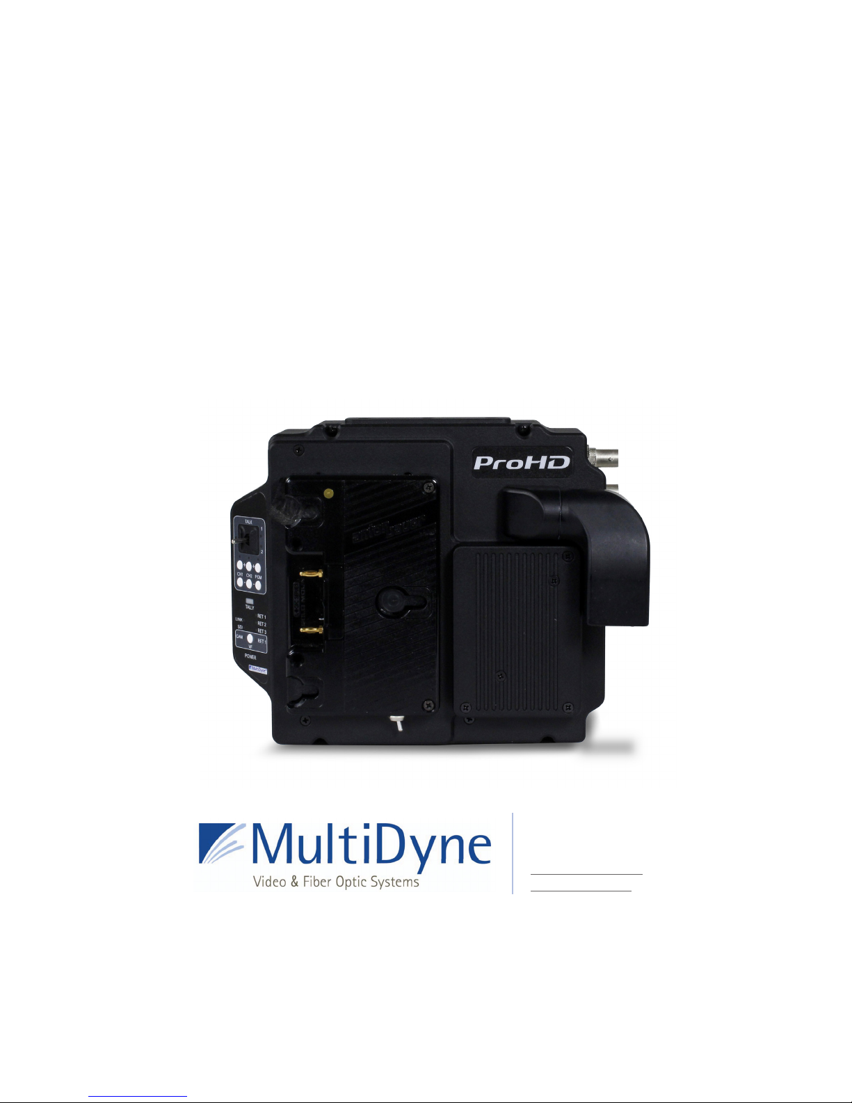
Camera Head Unit :
JVC Camera Silverback attachment procedure
Step 1: Remove the existing camera back and
battery plate.
(for more information visit JVC website: http://pro.jvc.com/splash.jsp)
Installation Instructions (cont.)
Installation Instructions
Unpacking the FS-900 Triple Studio Camera Interface System
Figure 1: JVC ProHD camera back
Items that are shipped with a particular
order option:
SMPTE Option:
Qty Description
1 FS-900BS1S Base Station
3 FS-900CAM1S Camera Head
3 Return video cables
3 Hirose Power cables
1 Line cord
1 Mounting Hardware kit
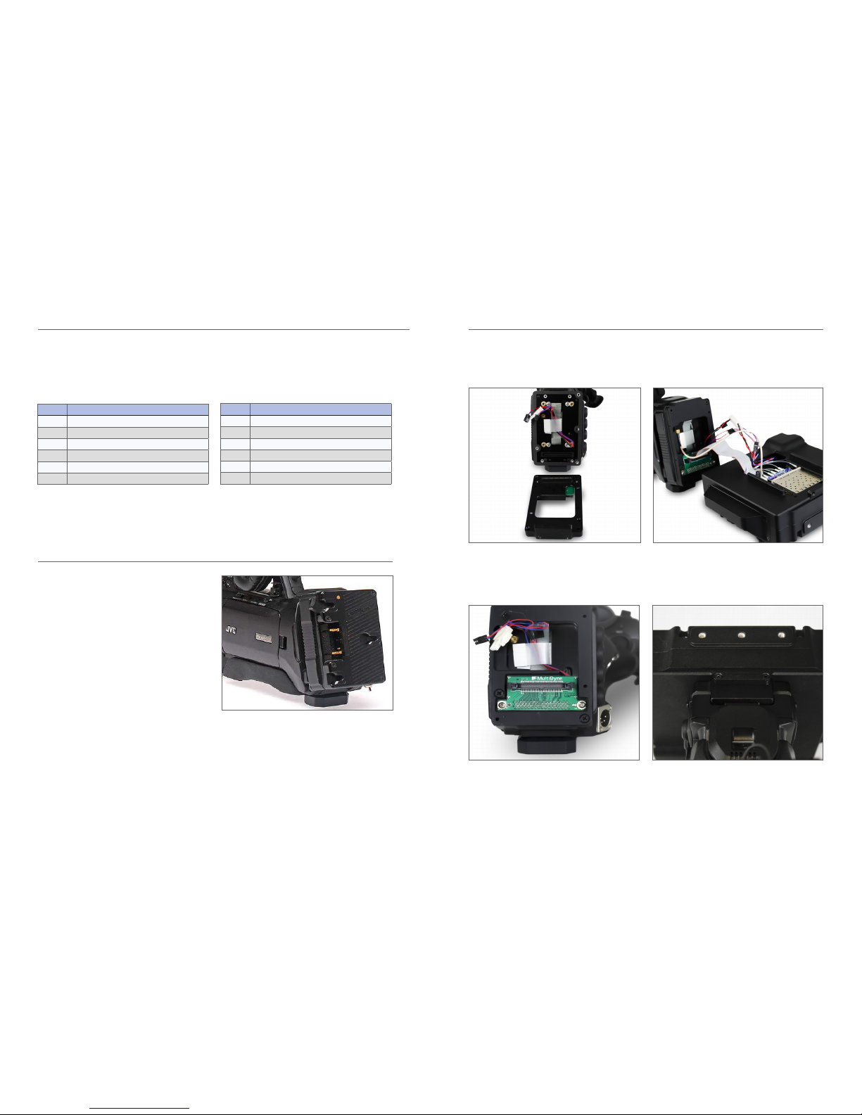
Figure 4: : Camera and Silverback connections
Figure 5: Final mount
Neutrik Option:
Qty Description
1 FS-900BS1N Base Station
3 FS-900CAM1N Camera Head
3 Return video cables
3 Hirose Power cables
1 Line cord
1 Mounting Hardware kit
Figure 3: Attaching PCB connector
Figure 2: Attaching camera mount plate
Step 4: Camera and Silverback connection
Connect the MCX connector, the power connector,
the battery data connectors and the camera interface
connector as show in the gure 4
Step 2: Attach camera mount plate
Position the camera mount on the back of the camera
and fasten the right screws to attach the camera
mount plate
Step 3: Attach PCB connector
Attach the camera connector PCB on back of the
camera mount plate”’
Step 5: Final mount
Install the camera back on the mounting plate and
fasten the six #4-40 screws on the mounting plate
Page 5

8 9
Camera Interface Signal Paths
e FS-900 Triple Studio Camera Interface System is
a camera video, audio, ethernet and data multiplexing system that installs between three separate JVC
ProHD GY-HM890U video cameras and their power
sources in addition, each camera connects via a single
ber optic cable to a common Base Station in a truck,
studio control room, or other video production facility. All of the video, audio and data is sent bi-directionally between the Base Station and each camera
over three separate single ber cables, one between
each camera and the common Base Station.
e Camera Head Unit is attached directly to the
camera. e Camera Head unit is designed to allow
the majority of the signals that connect between the
Camera and itself to ow thru a 68 pin connector
internal to the Camera and the Camera Head unit.
e FS-900 Triple Studio Camera Interface System
consists of the two main components:
1. e FS-900 Base Station
2. e FS-900 Camera Head
Model numbers of available options:
FS-900BS1S - Base Station with SMPTE connectors
FS-900BS1N- Base Station with Neutrik connectors
FS-900CAM1S- Camera Head with SMPTE connectors
FS-900CAM1N- Camera Head with Neutrik connectors
FS-900 System Description
3Gb/s HD-SDI 1 (camera video)
3Gb/s HD-SDI PGM return 1 (video)
3Gb/s HD-SDI return 2 (video)
Prompter: SDI → HDMI (common)
2 channel Intercom
2 channel PGM audio
Analog SD/HD reference
(common)
Camera 1 Tally (R,G)
Timecode
RS232/422/TTL Data 1
(camera control)
Ethernet 10/100/1000
3Gb/s HD-SDI 2 (camera video)
3Gb/s HD-SDI PGM return 1 (video)
3Gb/s HD-SDI return 2 (video)
Prompter: SDI → HDMI
(common)
2 channel Intercom
2 channel PGM audio
Analog SD/HD Reference
(common)
Camera 2 Tally (R,G)
Timecode
RS232/422/TTL Data 2
(camera control)
Ethernet 10/100/1000
3Gb/s HD-SDI (camera video 3)
3Gb/s HD-SDI PGM return (video 1)
3Gb/s HD-SDI return (video 2)
Prompter: SDI → HDMI
(common)
2 channel Intercom
2 channel PGM Audio
Analog SD/HD Reference
(common)
Camera 3 Tally (R,G)
Timecode
RS232/422/TTL Data 3
(camera control)
Ethernet 10/100/1000
Base Unit
Camera Unit 1 Camera Unit 2 Camera Unit 3
Page 6

10 11
MultiDyne FS-900 Triple Studio
Camera Interface System for JVC’s
GY-HM890 ProHD camcorde
e MultiDyne® Pro HD camera-mounted
ber-optic transceivers are used to “systemize”
HD, 2K and 4K Quad-Link 3G camcorders. It oers
versatility and the ability to congure a camera
system to specic applications. e camera is connected with a series of short patch cables
and then connected to the system’s base station
(RX) with a single ber-optic cable, which can be
located near the camera or miles away.
e FS-900BS1N (Neutrik Opticalcon)
and FS-900BS1S (SMPTE)
Supports 3G-SDI 1080p/60 camera feeds and
returns, and takes advantage of the camera’s builtin streaming engine for video-over-IP functionality.
Cost-ecient to support up to three cameras by
each base station, and redundant power supplies
provide up to 150 watts for each camera, as well as
prompters and
talent monitors.
Key Features
• Supports 1080 50/60p 3G-SDI camera feed
and returns.
• HDMI / SDI feeds for high-quality HD
teleprompters.
• Gigabit Ethernet for Video-over-IP and
web-based RCU.
• Dual redundant power supplies for
base station
Hybrid ber cable for Neutrik and SMPTE
Hybrid ber cable assemblies are compatible for easy mating to industry standard broadcast camera systems.
e rigorous qualication and intermateability testing program guarantees consistent and reliable results with
all compliant systems.
Detailed Description: Camera Head Unit - ConnectorsFS-900 JVC Triple Studio Camera Interface System Components
1. Battery Connector:
Anton Bauer Gold mount or V mount
2. Fiber-Optic Connector:
Use either SMPTE or Neutrik cable (depending
on option ordered) to connect to Base Unit.
3. Return 3 Video—HDMI Output Connector:
e Return 3 video channel sent from the Base
Unit to the Camera Head that has been converted
from SDI to HDMI inside the Camera Head Unit is
output on this HDMI connector.
4. Viewnder Video—BNC Output Connector:
e video output on this connector is either the
SDI video coming in from the Camera or the
Return 1 video channel sent from the Base Unit
depending on which input is selected via the
Viewnder Input Select Switch (#14 on page 12)
5. Return 1, 2, 3 Video—BNC Output Connector:
e Return video channel input into and sent
from the Base Unit to the Camera Head is output
on these BNC connector.
6. Auxiliary Power Output 1 & 2 Connectors
7. External Tally/GPIO Connector:
See Table 2 for pinout assignments.
8. Program Audio Output Connector:
See Table 3 for pinout assignments.
9. Ethernet Connector:
Use to connect Camera Head Unit to Ethernet.
10. Intercom Headset Connector:
See Table 4 for pinout assignments
2
1
3
5
4
5
5
7
9
8
10
6
Page 7

12 13
e Viewnder button on the Camera Unit’s control
panel is used to select the video source that is output
from the Viewnder BNC Connector. Pressing this
button will change between the Camera’s video
output and the Return 1 video being sent by the base
station. LED’s on the control panel indicate which
source is currently switched to the Viewnder output.
An external switch connected to the DB-15 GPIO
connector on the Camera Unit may also be used to
control the Viewnder output, please refer to the
pinout guide for pinout information. e Viewnder
select pin on the GPIO connector is typically used
with a momentary type pushbutton switch. When
this pin is connected to Ground, the Viewnder BNC
will output Return 1 video. When this pin is le open
or unconnected, the Viewnder BNC will output the
Camera’s video signal.
e Viewnder output can also be selected using the
RET button on the Lens. Note that this requires
GY-HM890U camera rmware A518-00FB, or later,
and this option is enabled in the Camera’s menu
under: Camera Function; User Switch Set, Return
Video Camera Return.
Viewnder Operation
1. Intercom Push-To-Talk Switch: Used to enable
talkback on CH 1, CH 2 or CH 1 & 2.
2. Intercom Talk Active LED Indicator: Blinks when
either CH1 or CH2 is enabled for talkback.
3. Intercom Channel 1 & 2 Talk Active LED
Indicator: Blinks when the PTT switch has been
used to enable talkback on CH 1 or CH2.
4. Intercom Channel 1 & 2 Audio Presence LED
Indicator: Illuminates when audio is present.
5. Program Audio Presence LED Indicator:
Illuminates when audio is present on either of the
two Program Audio channels sent from the Base
to the Camera Head units.
6. Intercom Channel 1 & 2 Audio Volume Control
Buttons: Controls the volume of the Intercom
7. Program Audio Volume Control Buttons:
Controls the volume of the Intercom Program
audio out in the intercom headset.
8. Tally Active LED Indicators: Illuminates Red for
PGM Tally, Green for PVW Tally.
9. Fiber Link Active LED Indicator: Illuminates when
there is a valid ber connection to the Base Unit.
10. Camera SDI Video Presence LED Indicator: Illu-
minates when the Camera SDI video is present.
11. Viewnder Camera Active LED Indicator:
Illuminates when the Camera SDI video is currently being routed thru to the Viewnder output.
12. Return 1, 2, 3 SDI Video Presence LED Indicator:
Illuminates when video is present on the Return
1,2, or 3 video channel.
13. Viewnder Return 1 Active LED Indicator: Channel 1 & 2 audio out in the intercom headset.
14. Viewnder Select Button: Camera Function User
Switch; Set, Return, VideoCamera Return.
15. Power LED Indicator: Illuminates when power is
applied to the Camera Head Unit.
Detailed Description: Camera Head Unit – Controls and Indicators
2
1
3
4
6
7
10
8
11
12
13
14
15
9
5
Page 8

14 15
e top portion of the Camera Unit’s control panel
is used to control intercom operation of the camera
operator’s headset. ese controls consist of: a pushto-talk (PTT) switch, volume control buttons, and
indicator LEDs. ere are additional controls located next to the headset connector for Mic Gain and
Sidetone adjustment. Mic Gain and Sidetone level are
adjusted using a small screwdriver.
e intercom headset connector can be used with
industry standard dual-mu or single-mu headsets.
Intercom Belt Packs cannot be plugged into the Camera Unit. When using dual-mu headsets, identical
audio will be present in both ears.
e volume controls allow for a mix of both intercom
channels and program audio all to be listened to in
the headset simultaneously. e LED above each
channel’s set of volume control buttons will illuminate whenever audio is present on that channel.
When adjusting the volume, these LED’s will rapidly
blink 3 times whenever the min or max volume setting has been reached.
e intercom Talkback switch, or PTT switch, provides
Momentary/Latching operation of the headset microphone to allow the operator to talk on a particular
intercom channel, or on both channels simultaneously.
For Momentary Mode, press and hold the PTT switch
up or down towards the intercom channel you wish
to speak on and then speak into the microphone.
e TALK and the selected intercom channel LED’s
will blink and the mic will remain open while the PTT
switch is held. Release the PTT switch when nished
talking. e mic will close and the TALK and channel
LED’s will turn o.
Latching Mode can be used for longer-term, handsfree operation. To talk on channel 1, quickly toggle
the PTT switch upwards towards CH1 and release.
e mic will latch open and the TALK and CH1 LED’s
will blink continuously. When nished talking, quick-
ly toggle the PTT switch upwards again and release.
e mic will then close and the TALK and CH1 LED’s
will turn o.
To talk on channel 2, quickly toggle the PTT switch
downwards towards CH2 and release. e mic will
latch open and the TALK and CH2 LED’s will blink
continuously. When nished talking, quickly toggle
the PTT switch downwards again and release. e mic
will close and the TALK and CH2 LED’s will turn o.
To talk on both channels 1 and 2 simultaneously, rst
quickly toggle the PTT switch upwards towards CH1
and release. e mic will latch open and the TALK
and CH1 LED’s will blink continuously. Next, quickly
toggle the PTT switch downwards towards CH2 and
release. e mic will stay open and now the TALK,
CH1 and CH2 LED’s will all blink continuously. When
nished talking, quickly toggle the PTT switch upwards and release to disengage CH1 (the CH1 LED will
turn o) then quickly toggle the PTT switch downwards and release to disengage CH2 (the CH2 LED
will turn o). e mic will close and the TALK, CH1
and CH2 LED’s will all turn o.
An external switch connected to the DB-15 GPIO
connector on the Camera Unit may also be used to
control Intercom Talkback operation, please refer to
the pinout guide for pinout information. Two mic
trigger GPI pins are provided, one for CH1 and one for
CH2. A single SPDT momentary type switch or 2 SPST
switches may be used.
Intercom Talkback operation can also be controlled
using the REC button on the Camera’s Lens. Note
that this requires GY-HM890U camera rmware
A518-00FB, or later, and this option can be enabled
in the Camera’s menu under: Camera Function à Lens
REC à (ICOM2, ICOM1, REC). Momentary and Latching
operation is supported from the REC button only on
the intercom channel that is selected in the menu.
Both channels cannot be activated simultaneously
from the REC button.
Intercom Operation
1. AC Mains Input 1 & 2 Connector: Provides power
to the base unit electronics and the camera head
units. AC Mains 1 is primary AC power input. AC
Mains 2 only provides redundant power to the
base station.
2. OpenGear Option Slot 1 & 2: For future use.
3. Camera 1, 2, & 3 Hybrid Fiber-Optic Connector:
Use either SMPTE or Neutrik cable (depending
on option ordered) to connect cameras to base
unit. Carries all data between camera head unit
and base unit and provides power to camera
head as well.
4. Program Audio & Intercom DB25 Connector:
Intercom and PGM Audio signals are connected
here
5. Return 1, 2, & 3 SDI Video Input BNC Connector:
Return video input channels to the base which
are sent to the three camera units..
6. Timecode Input BNC Connector: Timecode input
to Base Unit which is then sent to the three Camera Head Units.
7. Intercom 2-Wire/4-Wire Selector Switch: Selects
between 2-Wire mode or 4-Wire mode
8. Wire Intercom Autonull Switch: Toggling it up
performs an automatic nulling function on intercom CH1. Toggling it down performs this function
on intercom CH2.
9. Video Reference Input BNC Connector (looping):
Video input reference signal is connected here.
10. Camera 1 Timecode Output BNC Connector:
Timecode signal sent from Camera 1 thru Camera
Head 1 Unit.
11. Camera 1, 2, & 3 RCP Connector: Remote control
panel inputs
12. Tally & GPIO DB25 Connector: Connect Tally and
GPIO signals for each camera here.
13. Ethernet Connector: Cameras 1, 2, & 3
10/100/1000 mbs Ethernet port connections.
14. Camera 1, 2, & 3 SDI Video Output A & B BNC
Connector: SDI video channel from cameras
1, 2, & 3 available at these connectors. Two
copies of each camera’s video output are
provided on these BNC’s.
Detailed Description: Base Station – Connectors & Controls
21 3 3 3
4
6
798
10 11 11 12
14 13 14 13 14 13
5 5 5
Page 9

16 17
FS-900 Triple Studio Camera Interface connected to ProHD Base Unit
Fiber Installation and Power vs Distance. Up to 300 meters (1000 feet) on SMPTE 304 Hybrid Fiber
All HD, Video, Audio and control signals, plus up to 100 Watts of continuous 14VDC Power
ProHD Base Unit
All of the video signals coming from the camera and its accessories (viewnder, etc.) are fed to the FS-900 Triple Studio Camera Interface system’s 1RU base station enclosure via the SMPTE or opticalCON swivel connector,that also supplies power.
Application & UsageDetailed Description: Base Station – Controls and Indicators
1. Camera 1 LTC Presence LED Indicator:
Illuminates when a valid timecode signal is being
received from Camera 1
2. Cameras 1, 2, & 3 SDI Video, RCP Data,
Fiber Link LED Indicators: Illuminates when
the SDI video, RCP data, and Fiber Link from
Camerasis present.
3. SDI Return 1, 2, & 3 Video Presence LED
Indicator: Illuminates when the Return video
channels input has a valid signal on it.
4. Intercom Ch1 & Ch2 Audio Presence LED
Indicator: Illuminates when the Intercom Ch1
Audio channel has a valid audio signal on it.
5. Program Audio Presence LED Indicator:
Illuminates when the Program Audio channel has
a valid audio signal on it.
6. Return 1 SDI Video Presence LED Indicator:
Illuminates when the Return 1 video channel
input has a valid signal on it.
7. Power LED Indicator: Illuminates when the
Base Unit has AC power applied to it.
8. Menu Navigation Button: Controls front
panel TFT display. See Operations Section for
description.
9. TFT Display: See Operations Section for
description.
2 2 213 4 7 8
9
6
5
FS-900 Triple
Studio Camera Interface
ProHD Base Station
SMPTE
Camera x3
Program Audio
& Intercom
Return Video 1,2,3
Ethernet x3
Intercom
2-wire/
4-wire
Remote
Control x3
Tally & GPIO
Video
Output x3
Page 10

18 19
Signal Flow: Camera Head Signal Flow: Base Unit
Page 11

Camera 1
Top Menu
Camera 2
Top Menu
Camera 3
Top Menu
System Status
Fiber
Status
Base Top Menu
A/V Status
System Status
System Status
System Status
Fiber
Status
Fiber
Status
Fiber
Status
A/V Status
A/V Status
A/V Status
Camera
Top Menu
Home
20 21
Home Status Screen:
System Status
Base: OK
Camera1: OK
Camera2: OK
Camera3: OK
Back Home
Base Top Menu:
Base System Status
Fiber Status
A/V Status
System Status
Back Home
Cam Top Menu
Camera System Status
Camera 1
Camera 2
Camera 3
Back Home
Base Fiber Status Menu:
Base Fiber Status
Cam1 Cam2 Cam3
Rx1: -xxdBm -xxdBm -xxdBm
Rx2: -xxdBm -xxdBm -xxdBm
Rx3: -xxdBm -xxdBm -xxdBm
Back Home
Base A/V Status Menu:
Base Video Status
Cam1: SD/HD/3G Ret1 SD/HD/3G
Cam2: SD/HD/3G Ret2: SD/HD/3G
Cam3: SD/HD/3G Ret3: SD/HD/3G
Ref: NTSC/PAL/HD
Back Home
Base System Status Menu:
Base System Status
Main CPU Rev: ver
Display CPU Rev: ver
FPGA Rev: ver
Back Home
Operation Operation: Base Unit Operational Description
Page 12

22 23
Operation
Camera 2 A/V Status Menu:
Cam2 Video Status
Cam1: SD/HD/3G
Ret1: SD/HD/3G
Ret2: SD/HD/3G
Ret3: SD/HD/3G
Ref: NTSC/PAL/HD
Back Home
Camera 2 System Status Menu:
Cam2 System Status
CPU Rev: ver
FPGA Rev: ver
Vin: xx.x V
Power: xx.x W
Back Home
Camera 3 Top Menu
Camera 3 Menu
Fiber Status
A/V Status
System Status
Back Home
Camera 3 Fiber Status Menu
Cam3 Fiber Status
Rx Pwr Temp
1: -xxdBm deg C
2: -xxdBm deg C
3: -xxdBm deg C
4: -xxdBm deg C
5: -xxdBm deg C
Back Home
Camera 3 A/V Status Menu:
Cam2 Video Status
Cam1: SD/HD/3G
Ret1: SD/HD/3G
Ret2: SD/HD/3G
Ret3: SD/HD/3G
Ref: NTSC/PAL/HD
Back Home
Camera 3 System Status Menu:
Cam3 System Status
CPU Rev: ver
FPGA Rev: ver
Vin: xx.x V
Power: xx.x W
Back Home
Operation
Camera 1 Top Menu:
Camera 1 Menu
Fiber Status
A/V Status
System Status
Back Home
Camera 1 Fiber Status Menu
Cam1 Fiber Status
Rx Pwr Temp
1: -xxdBm deg C
2: -xxdBm deg C
3: -xxdBm deg C
4: -xxdBm deg C
5: -xxdBm deg C
Back Home
Camera 1 A/V Status Menu:
Cam1 Video Status
Cam1: SD/HD/3G
Ret1: SD/HD/3G
Ret2: SD/HD/3G
Ret3: SD/HD/3G
Ref: NTSC/PAL/HD
Back Home
Camera 1 System Status Menu:
Cam1 System Status
CPU Rev: ver
FPGA Rev: ver
Vin: xx.x V
Power: xx.x W
Back Home
Camera 2 Top Menu
Camera 2 Menu
Fiber Status
A/V Status
System Status
Back Home
Camera 2 Fiber Status Menu
Cam2 Fiber Status
Rx Pwr Temp
1: -xxdBm deg C
2: -xxdBm deg C
3: -xxdBm deg C
4: -xxdBm deg C
5: -xxdBm deg C
Back Home
Page 13

24 25
Intercom Audio
Number of Channels 2
Interface 2-Wire or 4-Wire
Compatibility RTS, Clear-Com
Headset MIC Type Dynamic
Headset MIC Impedance 200 Ohms nominal
Level, 4-Wire +4dBu nominal, +24dBu max.
Level, 2-Wire -10dBu nominal
Connector, Headset XLR-5
Connector, Base Unit DB25
Camera Remote Control
RCP Camera Control (Remote)
Type JVC RCP (RS232)
Connector, Camera Unit Internal 68-pin
Connector, Base Unit 6 pin Mini-DIN
Ethernet
Ethernet
Data Rates 10/100/1000 Base-T
Connector RJ45 Cat5e
Tally / GPIO
Input type Short to GND or TTL Low to Activate
Output Type Relay Contact Closure (30V, 2A max)
Connector, Camera Unit DB15
Connector, Base Unit DB25
Timecode
Type SMPTE/EBU LTC
Inputs Unbalanced, 15Vp-p max
Outputs Unbalanced, 3Vp-p max
Connector, Camera Unit Internal
Connector, Base Unit BNC
Technical SpecicationsTechnical Specications
SDI Video
Interface SMPTE ST259, ST292, ST424
Data Rate 270Mbps, 1.5Gbps, 3Gbps
Input/output Level 800mVp-p
Input/output Impedance 75 Ohms
Connector, Camera Unit BNC,
Connector, Base Unit BNC
Embedded Audio Supported Yes
Video Genlock (Reference)
Type Analog Black Burst, Tri-Level
Impedance 75 Ohms
Level 1Vp-p
Connector, Camera Unit Internal 68-pin
Connector, Base Unit BNC
Connector, Base Unit BNC
Embedded Audio Supported Yes
Analog Audio
Audio
Type Balanced Analog Line-Level
Level +4dBu nominal, +24dBu max.
Input Impedance > 10k ohms
Output Impedance 50 ohms
THD+N Better than 0.1%
Frequency Response +0.1 dB/-3dB, 20Hz to 20kHz
Connector, Camera Unit DB9
Connector, Base Unit DB25
Page 14

26 27
Electro-Optical
Operating Wavelengths 1471-1611nm
TX Laser Output Power 0dBm (Class 1 Laser)
Receiver Sensitivity -20dBm
Fiber Compatibility Single-mode
Optical Connector Types opticalCON DUO, SMPTE 304M
Power Supply
Power Input, Base IEC320, Universal Input, 90-250VAC, 50-60Hz
Power Input, Camera:
Remote Power Hybrid Fiber Connector, 54 VDC
Local Power Battery Mount (Anton Bauer or V-Mount), 11-17 VDC
Environmental
Operating Temperature 0 to 50°C
Operating Temperature 0 to 95% RH, non-condensing.
Technical Specications
Detail Connector Pinouts
Base Unit Intercom/Audio Connector Pinout
Number Description Number Description
1 2-Wire Intercom Pin2 / 4-Wire
Intercom Ch1 Output+
14 2-Wire Intercom Pin3 / 4-Wire
Intercom Ch2 Output+
2 4-Wire Intercom Ch1 Output- 15 4-Wire Intercom Ch2 Output3 GND 16 GND
4 4-Wire Intercom Ch1 Input+ 17 4-Wire Intercom Ch2 Input+
5 4-Wire Intercom Ch1 Input- 18 4-Wire Intercom Ch2 Input6 PGM Audio Ch1 Input+ 19 PGM Audio Ch2 Input+
7 PGM Audio Ch1 Input- 20 PGM Audio Ch2 Input8 GND 21 GND
9 GND 22 N/C
10 Intercom MIC Kill GPI Input 23 N/C
11 N/C 24 N/C
12 GND 25 GND
13 GND
Base Unit GPIO Connector Pinout
Number Description Number Description
1 Camera 1 Program (Red) Tally
GPI Input
14 GND
2 Camera 1 Preview (Green) Tally
GPI Input
15 GND
3 Camera 1 GPI Input 16 GND
4 Camera 1 GPO Output 17 GND
5 Camera 2 Program (Red) Tally
GPI Input
18 GND
6 Camera 2 Preview (Green) Tally
GPI Input
19 GND
7 Camera 2 GPI Input 20 GND
8 Camera 2 GPO Output 21 GND
9 Camera 3 Program (Red) Tally
GPI Input
22 GND
10 Camera 3 Preview (Green) Tally
GPI Input
23 GND
11 Camera 3 GPI Input 24 GND
12 Camera 3 GPO Output 25 GND
13 +12VDC Output
Page 15

28
Detail Connector Pinouts
Camera Unit GPIO Connector Pinout
Number Description Number Description
1 Program (Red) Tally GPO
Output
9 GND
2 Preview (Green) Tally GPO
Output
10 GND
3 GPO Output 11 Intercom MIC Ch1 PTT GPI
Input
4 GPI Input 12 Intercom MIC Ch2 PTT GPI
Input
5 Viewnder Input Select GPI
Input
13 N/C
6 GND 14 N/C
7 GND 15 +12VDC Output
8 GND
Camera Unit Audio Connector Pinout
Number Description Number Description
1 GND 6 PGM Audio Ch1 Output+
2 PGM Audio Ch1 Output- 7 GND
3 PGM Audio Ch2 Output+ 8 PGM Audio Ch2 Output4 GND 9 N/C
5 N/C
Camera Unit Intercom
Headset Audio Connector Pinout
Number Description
1 GND
2 MIC Input+
3 GND
4 Audio L Output
5 Audio R Output
Camera Unit Auxiliary Power
Output Connector Pinout
Number Description
1 GND
2 N/C
3 N/C
4 +12VDC Output
Page 16

©2016 MultiDyne, Inc MDDOC00170.RevA November, 2016
110 Newton Place
Hauppauge, NY 11788
(800)-488-8378 / (516)-671-7278
sales@multidyne.com
www.multidyne.com
 Loading...