

Page 1
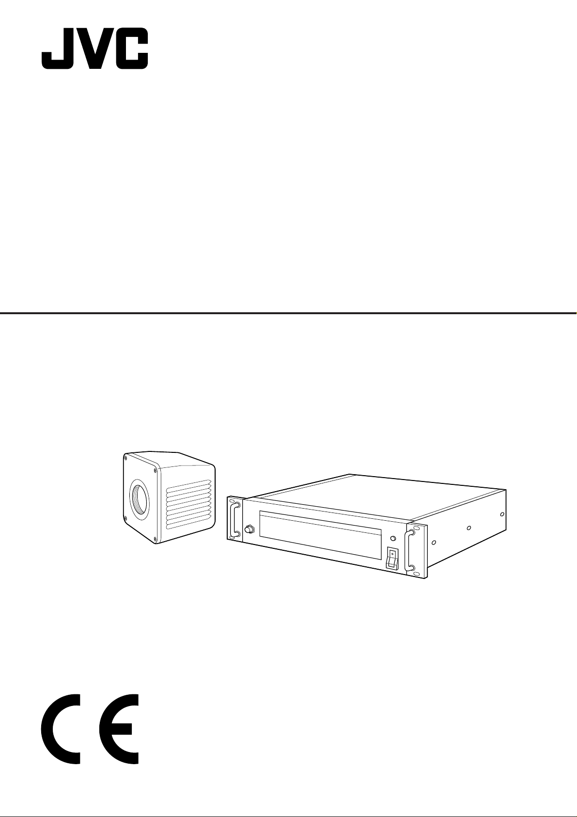
MICRO HD CAMERA
Instructions
DZ-VCA1SE
LYT0468-001B
Page 2

Applications
Micro HD camera system can be used for following applications;
(This system should only be operated by doctors or authorized persons.)
(1)Operation microscope in OR
neurosurgery, eye surgery, orthopedic surgery and etc.
(2)Slit lamp microscope
(3)Pathology microscope
(4)Operation Room camera shooting operation area.
(5)Endoscope operation in OR.
Above applications, the system can supply HD signals to HD monitor for display and to HD VTR for recording/playback.
Also, by using SCSI I/F the system can supply digitized HD still picture to Zip drive for recording. Digitized still pictures
in recorded removable disk can be stored into hard disc drive in PC.
Dear Customer,
Thank you for purchasing the MICRO HD CAMERA. Before use, please read the safety information and precautions
contained in the following pages to ensure safe use of your new MICRO HD CAMERA.
Importer’s name & address
J.P.U.: JVC PROFESSIONAL PRODUCTS (UK) LIMITED
ULLswater House, Kendel Avenue, London W3 OXA, United Kingdom
TEL: (0181) 896-6000
FAX: (0181) 896-6060
J.P.G.: JVC PROFESSIONAL PRODUCTS GmbH
Grüner Weg 10, 61169 Fiedberg/Hessen, Germany
TEL: (06031) 6050
FAX: (06031) 605180
SOME DO’S AND DON’TS ON THE SAFE USE OF EQUIPMENT
This equipment has been designed and manufactured to meet international safety standards but, like any electrical
equipment, care must be taken if you are to obtain the best results and safety is to be assured.
DO read the operating instructions before you attempt to use the equipment.
DO ensure that all electrical connections (including the mains plug, extension leads and interconnections between
pieces of equipment) are properly made and in accordance with the manufacturer’s instructions. Switch off
and withdraw the mains plug when making or changing connections.
DO consult your dealer if you are ever in doubt about the installation, operation or safety of your equipment.
DO be careful with glass panels or doors on equipment.
DON’T continue to operate the equipment if you are in any doubt about it working normally, or if it is damaged in any
way — switch off, withdraw the mains plug and consult your dealer.
DON’T remove any fixed cover as this may expose dangerous voltages.
DON’T leave equipment switched on when it is unattended unless it is specifically stated that it is designed for
unattended operation or has a standby mode. Switch off using the switch on the equipment and make sure
that your family knows how to do this. Special arrangements may need to be made for infirm or handicapped
people.
DON’T use equipment such as personal stereos or radios so that you are distracted from the requirements of road
safety. It is illegal to watch television whilst driving.
DON’T listen to headphones at high volume, as such use can permanently damage your hearing.
DON’T obstruct the ventilation of the equipment, for example with curtains or soft furnishings. Overheating will cause
damage and shorten the life of the equipment.
DON’T use makeshift stands and NEVER fix legs with wood screws — to ensure complete safety always fit the
manufacturer’s approved stand or legs with the fixings provided according to the instructions.
DON’T allow electrical equipment to be exposed to rain or moisture.
ABOVE ALL
— NEVER let anyone especially children push anything into holes, slots or any other opening in the case — this could
result in a fatal electrical shock;
— NEVER guess or take chances with electrical equipment of any kind — it is better to be safe than sorry!
2
Page 3

Precautions on installing medical electrical
equipment (Safety and hazard prevention)
For the safe use of this equipment, be absolutely sure to follow the guidelines below.
1. Leave installation of the Mobile Video Cart and the unit to a specially trained service man.
2. Be absolutely sure to use the separately sold AA-V31E isolation transformer and AC adapter AA-V112E.
3. There are openings in the equipment. Fire or electric shock may result if liquid splashes inside one of
these openings. The front of the JVC-specified video cart has an opening. To prevent any possible problems, please set the cart in a reasonable position and use carefully. JVC cannot guarantee the total system
when using an unspecified video cart.
Cart information
Please use the VS5402.X or VS6300.X Mobile Video Cart to house the equipment.
(1)Maximum load
• Additional load: 225 kg
• Monitor shelf: 35 kg
(2)Front two casters have brakes.
• When using mobile video cart, two brakes should be set for safety after setting the position of the cart.
(3)Important notice 1
• When using a mobile cart in OR, as the cart has no front cover, precautions to avoid splashing at front area of it
should be taken.
• When moving a mobile cart in OR, precautions to avoid crossing over the power cord of the cart.
• When using a mobile cart in OR, precautions to avoid power cord of the cart to be caught by foot should be
taken.
(4)Important notice 2
• When mounting monitor on a mobile cart, we strongly recommend the use of a monitor shelf and monitor strap
for safety. (Refer to the following figure.)
(5)Equipotential terminals are located inside the cart
The back panel of the cart can be easily opened without any tool to gain access to the terminals.
ex.) Mobile Video Cart VS5402.X
For medical use, please use the JVC Isolation Transformer, AA-V31E, and JVC AC Power
Adapter, AA-V112E, in order to meet the following classifications.
(1) Class 1 Equipment powered by an external electrical power source.
(2) Type BF Applied part (Degree of protection against electric shock)
The specifications for the AA-V31E and AA-V112E are given on page 26.
3
Page 4
Safety precautions
Please Read Before Use
WARNING:
TO PREVENT FIRE OR SHOCK
HAZARD, DO NOT EXPOSE THIS
UNIT TO RAIN OR MOISTURE.
CAUTION:
This MICRO HD CAMERA should
be used with a power supply of
AC 120 V , 50 Hz only.
To prevent electric shocks and
fire hazards, DO NOT use any
other power supply.
WARNING:
This camera head, camera control unit, camera cable and video
adapter are not sterilized.
WARNING:
The use of ACCESSORY
equipment not complying with
the equivalent safety
requirements of this equipment
may lead to a reduced level of
safety with the resulting system.
Consideration relating to the
choice of accessories shall
include:
– use of the accessory in the
vicinity of the patient
– evidence that the safety of the
accessory has been certified in
accordance with the
appropriate IEC 60601-1 and/or
IEC 60601-1-1 harmonized
national standard.
WARNING:
When using in an ENDOSCOPE
application, to prevent fire or
shock hazard, the equipotential
terminals inside the video cart
should be connected to the equipotential terminals of the isolation transformer and light source
for the endoscope. Use the endoscope in accordance with
IEC60601-1 and IEC60601-2-18.
WARNING:
The HD Monitor requires an AC
120 V power supply.
To prevent electric shock and fire
hazard, DO NOT plug directly into
a hospital wall outlet.
WARNING:
In order to avoid the risk of fire
and shock hazards, please use
only the equipment specified in
this instruction manual.
4
Page 5

Important product safety instructions
Electrical energy can perform many useful functions. But
improper use can result in potential electrical shock or
fire hazards. This product has been engineered and
manufactured to assure your personal safety. In order
not to defeat the built-in safeguards, observe the following basic rules for its installation, use and servicing.
ATTENTION:
Follow and obey all warnings and instructions marked
on your product and its operating instructions. For your
safety, please read all the safety and operating instructions before you operate this product and keep this
booklet for future reference.
INST ALLATION AND DISPOSAL
1. Grounding or Polarization
Precautions should be taken so that the grounding or
polarization of an appliance is not defeated.
2. Power Sources
Operate your product only from the type of power source
indicated on the marking label. If you are not sure of the
type of power supply to hospital, consult your product
dealer or local power company. If your product is
intended to operate from battery power, or other
sources, refer to the operating instructions.
3. Overloading
Do not overload wall outlets, extension cords, or integral
convenience receptacles as this can result in a risk of
fire or electric shock.
4. Power Cord Protection
Power supply cords should be routed so that they are
not likely to be walked on or pinched by items placed
upon or against them, paying particular attention to
cords at plugs, convenience receptacles, and the point
where they exit from the product.
5. Ventilation
Slots and openings in the cabinet are provided for
ventilation. To ensure reliable operation of the product
and to protect it from overheating, these openings must
not be blocked or covered.
• Do not block the openings by placing the product on a
bed, sofa, rug or other similar surface.
• Do not place the product in a built-in installation such
as a bookcase or rack unless proper ventilation is
provided or the manufacturer’s instructions have been
adhered to.
6. Wall or Ceiling Mounting
The product should be mounted to a wall or ceiling only
as recommended by the manufacturer.
7. Storage Location
Do not store this product in a humid location, such as
near a window or an air conditioner, nor in a hot location,
such as near a heater.
8. Disposing of the Product
Always sterilize this product before disposing of it. (See
page 6.)
When discarding equipment, environmental problems
must be considered and the local rules or laws governing the disposal must be followed strictly.
FOR U.K. CUSTOMERS
If the socket outlets in hospitals are not suitable for the
plug supplied with this appliance, it should be cut off and
an appropriate 3 pin plug fitted. For details, refer to the
instructions described below.
Note: The plug severed from the mains lead must be
destroyed, as a plug with bared flexible cord is
hazardous if engaged in a live socket outlet.
Special Instructions for U.K. Model
IMPORTANT
THE WIRES IN MAINS LEAD ARE COLOURED
IN ACCORDANCE WITH THE FOLLOWING
CODE:
Blue: NEUTRAL
Brown: LIVE
As the colours of the wires in the mains lead of this
apparatus may not correspond with the coloured
markings identifying the terminals in your plug,
proceed as follows: The wire which is coloured BLUE
must be connected to the terminal which is marked
with the letter N or coloured BLACK. The wire which
is coloured BROWN must be connected to the
terminal which is marked with the letter L or coloured
RED. Making sure that neither core is connected to
the earth terminal of the three pin plug.
USE
1. Accessories
To avoid personal injury:
• Do not place this product on an unstable cart, stand,
tripod, bracket, or table. It may fall, causing serious
injury to a child or adult, and serious damage to the
product.
• Use only with a cart, stand, tripod, bracket, or table
recommended by the manufacturer or sold with the
product.
• Use a mounting accessory recommended by the
manufacturer and follow the manufacturer’s instructions for any mounting of the product.
• Do not try to roll a cart with small casters across
thresholds or deep-pile carpets.
2. Product and Cart Combination
A product and cart combination
should be moved with care. Quick
stops, excessive force, and uneven
surfaces may cause the product and
cart combination to overturn.
3. Water and Moisture
Do not use this product near water—for example, near a
bath tub, wash bowl, kitchen sink or laundry tub, in a wet
basement, or near a swimming pool and the like.
PORTABLE CART WARNING
(Symbol provided by RETAC)
5
Page 6

Important product safety instructions (continued)
4. Object and Liquid Entry
Never push objects of any kind into this product through
openings as they may touch dangerous voltage points or
short-out parts that could result in a fire or electric
shock. Never spill liquid of any kind on the product.
5. Attachments
Do not use attachments not recommended by the manufacturer of this product as they may cause hazards.
6. Cleaning
Unplug this product from the wall outlet before cleaning.
Do not use liquid cleaners or aerosol cleaners. Use a
damp cloth for cleaning.
7. Sterilization
Before using the endoscope, always be sure to sterilize
the laparoscope video adapter, the HD camera head,
and the camera cable.
8. Heat
The product should be situated away from heat sources
such as radiators, heat registers, stoves, or other
products (including amplifiers) that produce heat.
3. Replacement Parts
When replacement parts are required, be sure the
service technician has used replacement parts specified
by the manufacturer or have the same characteristics as
the original part. Unauthorized substitutions may result
in fire, electric shock or other hazards.
4. Safety Check
Upon completion of any service or repairs to this product, ask the service technician to perform safety checks
to determine that the product is in safe operating condition.
5. Operational Life of the Product
Regular maintenance and inspection is essential for
ensuring safe and long-lasting operation of this product.
Inspect and maintain the product before and after use,
and also have regular maintenance performed by a
specialist.
STERILIZATION:
The camera head with camera cable and video
adapter can be sterilized with ethylene oxide (EO)
and Sterad (50, 100, 100S, 500) supplied by Johnson
& Johnson Medical Inc.
SERVICING
1. Servicing
If your product is not operating correctly or exhibits a
marked change in performance and you are unable to
restore normal operation by following the detailed
procedure in its operating instructions, do not attempt to
service it yourself as opening or removing covers may
expose you to dangerous voltage or other hazards.
Refer all servicing to qualified service personnel.
2. Damage Requiring Service
Unplug this product from the wall outlet and refer
servicing to qualified service personnel under the
following conditions:
a. When the power supply cord or plug is damaged.
b. If liquid has been spilled, or objects have fallen into
the product.
c. If the product has been exposed to rain or water.
d. If the product does not operate normally by following
the operating instructions. Adjust only those controls
that are covered by the operating instructions as an
improper adjustment of other controls may result in
damage and will often require extensive work by a
qualified technician to restore the product to its
normal operation.
e. If the product has been dropped or damaged in any
way.
f. When the product exhibits a distinct change in
performance—this indicates a need for service.
Ethylene oxide
Desorbtion time for ethylene oxide after using aerator:
more than 18 hours
Desorbtion time is based on the following sterilization
parameters:
Ethylene oxide gas : Ethylene oxide 20% and CO2
80%
Temperature : 40˚ to 60˚C
Humidity : 40 to 60% RH
Ethylene oxide density: 500 to 600 mg/l
Desorbtion method : Aeration
Aerator : 50˚C and more than 18 hours
(In room temperature it is
required more than 48 H)
Note: Deterioration of camera cable
Due to ethylene oxide, rubber part of camera
cable may cause deterioration.
Depending on the frequency of use, however at
least once a year, an expert must check the
device.
Sterad (H2 O2 plasma)
In the case of using Sterad, please follow the instruction of the manufacturer. Because of using Sterad
many times, some cosmetic changes can be observed. However, the functions of HD camera system
are not affected by those.
6
Page 7

Precautions
Safety precautions
● Do not damage or modify the power cable. Doing so
could result in current leakage or electric shock.
● To protect the camera and avoid electric shock
hazards, always disconnect the power cord of the AC
power adapter from the AC outlet when the camera is
not in use for an extended period.
● Make sure that no flammable objects, water, or bits
of metal get inside the unit. These could damage the
unit or cause a malfunction.
● Whenever an anomaly (unusual noise, smell or
smoke) occurs, immediately turn off the main unit's
power, unplug the power cord, and consult your
nearest JVC dealer.
● Never use digital equipment such as portable telephones or video cameras when using this unit as this
may cause a malfunction.
Handling precautions
● For extended product life, avoid using and storing the
unit in places subject to the following conditions:
• extreme heat or cold
• vibrations
• dust or soil
• high humidity
• strong noise source
● The environmental temperature under which this unit
can be operated is limited by the image sensing
device. Use this unit within an environmental
temperature range of from +5˚C to +35˚C (41˚F to
95˚F).
● Avoid strong vibrations or violent shocks to this unit
during installation or transportation.
● If the power voltage is too high or too low, the service
life of this unit may be decreased and optimum
performance may not be assured.
● Do not plug in or unplug the camera cable connector
while this unit turned on. Doing so could cause a
malfunction.
● Wipe the cabinet clean with a soft cloth. To remove
excessive dirt, clean the unit with a soft cloth dipped
in a mild detergent diluted with water. Wring out any
excess liquid before wiping. Use a dry cloth to dry
the unit. Do not use a volatile liquid such as benzene, thinner or alcohol. These may damage the
cabinet surface or the coating.
● Be sure to use this unit in combination with the
components described in “Micro HD camera system
component list” on page 24. Do not use this unit near
strong radio sources such as a radio, TV or portable
phone, or near devices that produce a strong electromagnetic field such as a transformer or motor as this
may generate noise in the picture or cause changes
in image colour.
● Do not bring an electronic scalpel or other sources of
electronic noise near this product. Doing so can
interfere with the monitor display.
● When using a wireless microphone and receiver with
this unit, check them beforehand to ensure that noise
does not enter the wireless receiver.
If a problem develops concerning the
operation of this product while it is being
employed as an endoscopy system during
surgery, etc., take the appropriate action as described
below:
● Problem with the endoscope
The lamp for the light source may have been
burned out. Please read the operating manual for
details on replacing the lamp.
● Problem with the Micro HD Camera
If a problem with the operation of the monitor
screen develops and the normal screen is no
longer displayed, turn the power off and then turn
the power back on again.
● Check the following items before using the product.
(1)Make sure that the product is grounded properly.
(2)Make sure that all of the cords are connected
properly.
(3)When using this product in conjunction with other
equipment, consult a specialist in order to minimize any risk of misoperation or misdiagnosis.
(4)Make sure that the product has been sterilized.
● Pay attention to the following while using the product.
(1)Make sure that the patient is not experiencing any
distress.
(2)Make sure that all of the equipment is operating
correctly.
(3)Make sure that the patient does not touch the
product.
● Pay attention to the following after using the product.
(1)Following the prescribed procedure, return the
product to its original state before it was used,
and then turn the power off.
(2)When disconnecting the cords, do not pull on the
cords with undue force.
(3)Storage location
• Avoid locations where the product may get wet.
• Avoid locations with extremes in air pressure,
temperature, or humidity; poor ventilation;
exposure to direct sunlight; high levels of dust;
high levels of chlorine or sulfur compounds.
• Avoid storing the product on an unstable
surface; for example, one that is on a slope or is
exposed to vibration or physical shocks.
• Avoid storing the product in a location that is used
to store chemicals or where gases are present.
● Clean the product, its accessories, and the cords so
that they are ready for use the next time that they are
needed.
● If the product malfunctions, do not attempt to repair it
yourself. Place a label on it that clearly indicates that
it is “out of order” and contact a repair specialist.
● Do not attempt to modify the product.
● Equipment not suitable for use in the presence of a
flammable anaesthetic mixture with air or oxygen or
nitrous oxide.
7
Page 8
Precautions (continued)
Inspection and maintenance
(1)The product and its components must be inspected
regularly by a specialist. (The product should be
inspected once every three times that it is used, or
once every two months.)
(2)When using the product after it has not been used for
at least one month, confirm that the product still
operates normally and safely before attempting to
actually use it.
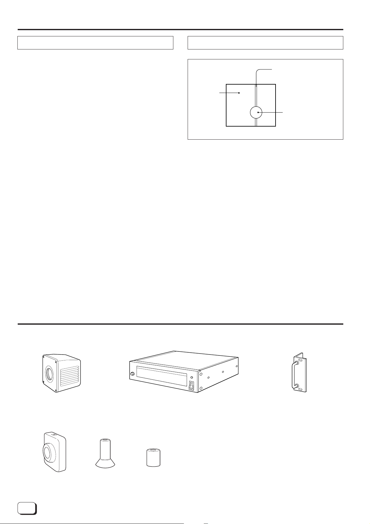
Phenomena peculiar to CCDs
Pale, vertical streaks
appear in the picture.
Monitor
screen
High-intensity subject
(electric light, lamp,
the sunlight, etc.)
The following CCD-related phenomena may appear on
the view screen during shooting. These are caused by
the CCD and are not malfunctions.
Smear phenomenon
Occurs when a high-intensity subject is shot.
Aliasing distortion
Striped patterns or lines appear as jagged patterns.
Standard construction
Camera head
Camera control unit
White or coloured luminescent spot
When this unit is operated for a long time under high
temperature, a white or coloured luminescent spot may
appear on the screen. In this case, it is necessary to
lower the environmental operating temperature.
When a moving subject is shot, lines and patterns may
appear jagged.
Handle x 2
Screw x 8
Washer x 4
Handle set
Insulating rubber covers x3
8
Page 9

Contents
Features
Applications...........................................................2
Precautions on installing medical electrical
equipment (Safety and hazard prevention) ........... 3
Safety precautions ................................................4
Important product safety instructions ....................5
Precautions
Safety precautions............................................7
Handling precautions........................................7
Inspection and maintenance.............................8
Phenomena peculiar to CCDs.......................... 8
Standard construction ...........................................8
Features ................................................................ 9
Connections ........................................................ 11
Names of parts and their functions
Camera control unit (front panel)....................12
Camera control unit (rear panel).....................13
Camera head..................................................13
Gain control section........................................14
Shutter control section....................................15
White balance control section.........................16
Mode control section ......................................17
Menu control section ......................................18
Preparation
Installing a lens...............................................20
Installing the camera control unit....................20
Before shooting
Setting the switches for white balance
adjustment ......................................................21
Back focus adjustment ...................................21
Basic operation
White balance adjustment (auto)....................22
White balance adjustment (manual)...............22
White balance adjustment (preset).................22
Connectors..........................................................23
Micro HD camera system component list............24
Specifications ...................................................... 25
Thank you for purchasing the
DZ-VCA1SE MICRO HD CAMERA.
● Compact, lightweight design
Thanks to the incorporation of 1/3-inch CCDs, the
camera head's outer dimensions have been reduced
to a compact 59 (W) x 70 (H) x 79 (D) mm and its
weight to only 230 g.
(1/3 the volume and 1/6 the weight of an ordinary HD
camera) The CCU (camera control unit) can be
mounted in a standard EIA 19-inch rack (2-unit size).
● High resolution
A total of four NTSC 1/3-inch CCDs are used (2 for G
and one each for R and B). Utilizing a newly-developed 4-CCD dual green system and digital signal
processing, this camera is able to produce extremely
high horizontal resolution of more than 800 TV lines
and vertical resolution of more than 650 TV lines
(approx. twice that of NTSC). The aspect ratio is 4:3.
● System construction
HDTV studio standard (compliant with ITU-R Rec.
709) sync signals are used, allowing recorded picture
to be played back with high picture quality when an
HDTV VCR such as the W-VHS VCR is used.
A cost-effective, high-picture-quality system can be
configured using a multi-scan computer monitor.
● Automatic sensitivity control
The automatic sensitivity control combines automatic
sensitivity control with ALC and electronic iris (ALC +
EEI) to allow trouble-free shooting under lighting
conditions ranging from low to high intensity.
● Electronic shutter function
A built-in 1/2000-sec. electronic shutter function
allows capture and analysis of fast-moving subjects.
● Flicker-free mode
Greatly reduces the flickering caused by shooting
under a fluorescent lamp in locations using 50-Hz
cycles.
● Colour bar generator
A full colour bar generator is built in for easy system
adjustment.
● Switchable positive/negative signal
Signals can be inverted with a switch, allowing
conversion of a negative film to a positive picture.
● Automatic internal/external sync switching
Useful for systematic operations, such as multi-
camera video processing, in combination with other
devices.
● 2H contour provided as standard
Contour compensation is performed both horizontally
and vertically to assure sharp, clear pictures.
• JVC cannot be responsible for any loss or
damage to recorded material in the event
that the colour video camera, VCR, or video
cassette malfunctions during recording.
9
Page 10
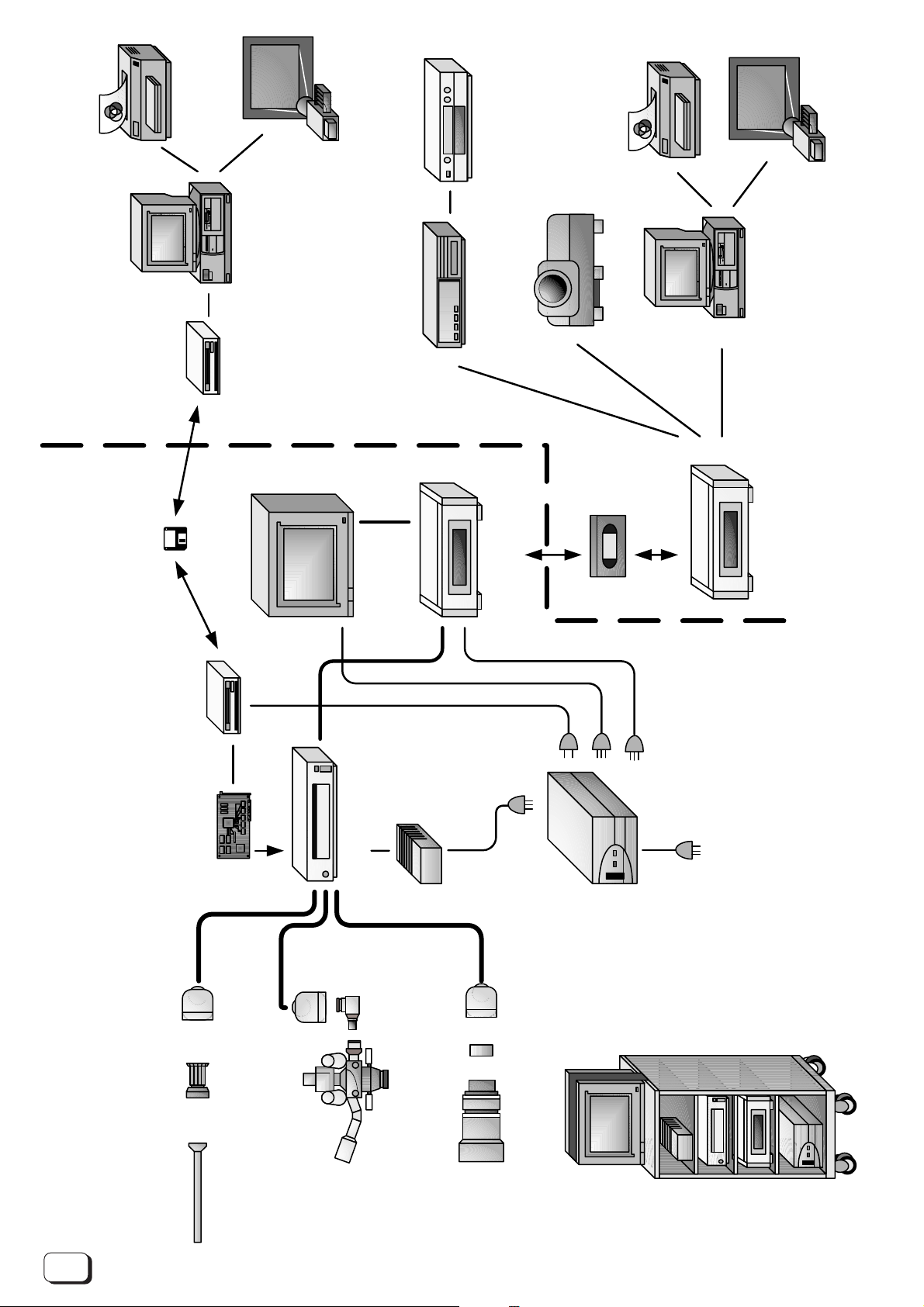
Camera head
DZ-VCA1SE
Endoscope adapter
(fixed lens) GL-V63U
(zoom lens) GL-V64U
When connecting the camera
to an operation microscope
Microscope
adapter
GL-V61U
When connecting the camera to
a zoom lens
1/2” Bayonet mount adapter
GL-V62U
CCU (camera control unit)
DZ-VCA1SE
SCSI board
built into CCU
ZIP drive
(Z250S)
4:3 HD monitor
HV-M2000V
W-VHS
SR-W7MAE
AC power
adapter
AA-V112 E
Isolation transformer
AA-V31E
ZIP drive
(disk drive)
Removable disk
Inside the Operating Room
Windows (95, 98, NT4.0)
Down-converter
(HD to NTSC or PAL)
DV or S-VHS, etc.
Macintosh
or
Windows (95, 98, NT4.0)
with video capture board
D-ILA projector
Video
cassette
SLIDE
Mobile video cart
iTD GmbH VS5402.X or VS6300.X
* Before using the endoscope, always be sure to sterilize the
endoscope video adapter, the camera head, and the camera cable.
W-VHS
SR-W7MAE
When connecting the camera to
an endoscope
Outside the Operating Room
SLIDE
Printer
LCD projector
Printer
LCD projector
■Micro HD Camera System Configuration Diagram
10
Page 11
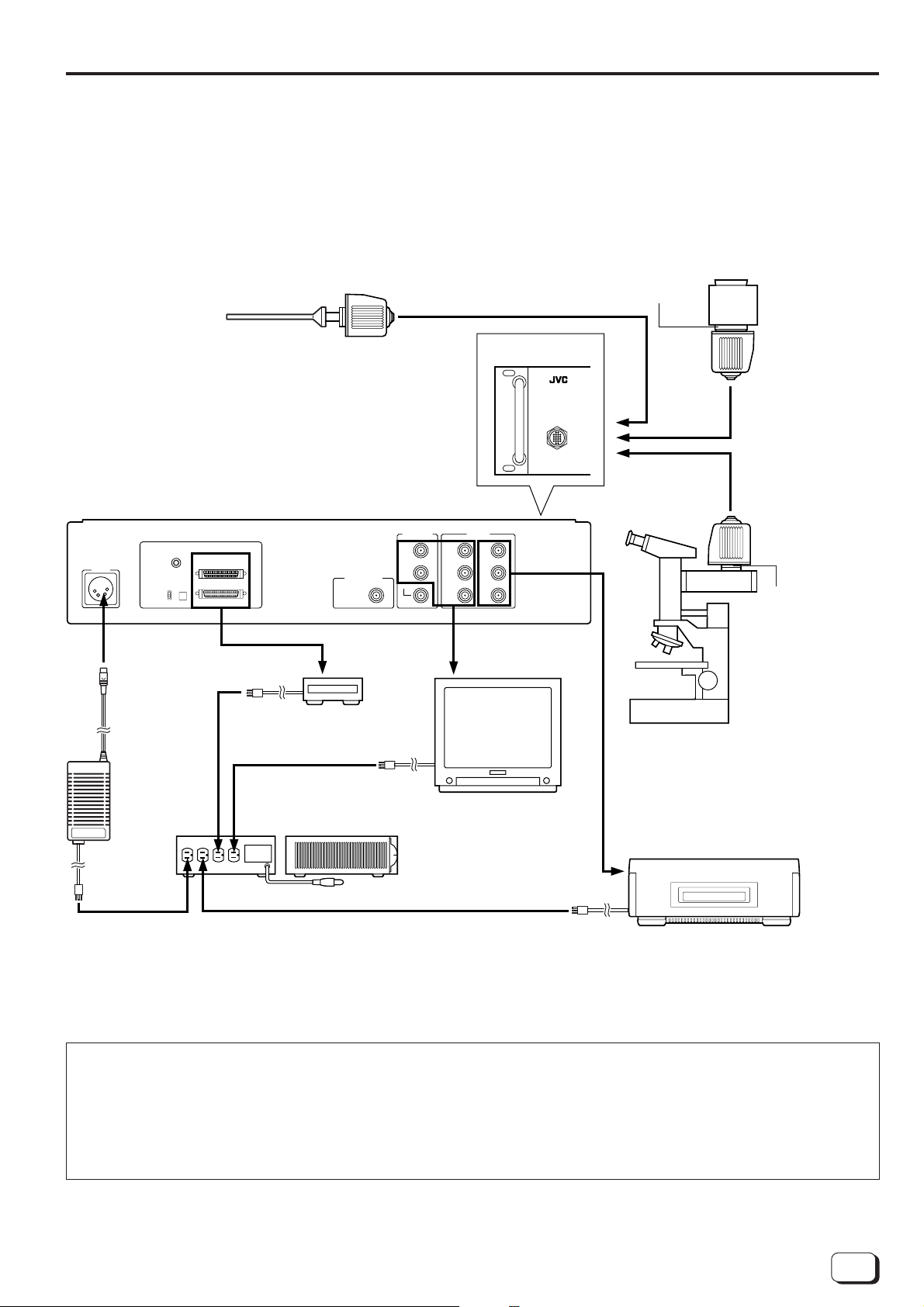
Connections
■Connection example
Notes:
• Do not connect this camera to equipment other than that depicted in these connection diagrams.
• Always be certain to use the AA-V31E Isolation Transformer.
Endoscope application Operation field application
Endoscope Video Adapter GL-V63U*
Endoscope Video Zoom Adapter GL-V64U*
Endoscope
* Always use an adapter that is designed for the Endoscope.
Camera control unit (rear panel)
DC-IN
Remote
Trigger
on
off
Termination SCSI ID
SCSI
DC 12 V
Front panel
GEN-LOCK IN
VS / C. SYNC
(
75Ω
SYNC OUT
HD
VD
C. SYNC
)
HD OUT
GBY
P
B
RPR
RGB signal HD video signal
(Y, PB, PR)
1/2" bayonet mount
conversion adapter
(GL-V62U)
CAMERA
Lens
(commercially
available)
Camera head
Camera cable
VC-V10 or VC-V3
(optional)
Camera head
Microscope
adapter GL-V61U
(optional)
ZIP drive
Z250S
Operation microscope application
AC power
adapter
(AA-V112E)
Isolation transformer
AA-V31E
HD Monitor
HV-M2000V
W-VHS VCR SR-W7 MAE
AC 230 V
• The camera head and camera control unit are adjusted as a set. Be sure the serial numbers match.
Optimum picture quality may not be obtained if a different combination is used.
• When the system is connected, check that current leakage from this connection does not surpass the specified
level. Also, be absolutely sure to use an AA-V31E isolation transformer.
• If the exterior of the isolation transformer is corroded, inadequate grounding may result. Have the exterior
replaced by your local JVC dealer.
11
Page 12
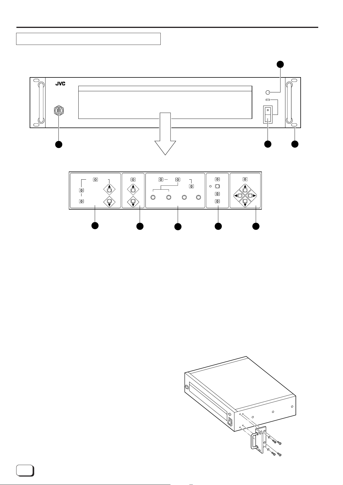
Names of parts and their functions
Camera control unit (front panel)
CAMERA CONTROL UNIT DZ-VCA1SE
GAIN SHUTTER WHITE BALANCE MENUMODE
CAMERA
PUSH OPEN
POWER
ON
OFF
2
I
O
3
Interior of the function box
AUTO MANUAL
ALC ALC + EEI
NORMAL
OVER UNDER
GAIN
NORMAL
SHUTTER WHITE BALANCE MENUMODE
OFF SET.
ON
V. SCAN
4
1 [POWER] power switch and
power indication LED
2 [PUSH OPEN] door button
Press to open the function box.
3 [CAMERA] camera cable connector
Connect to the camera head using the optional
camera cable.
4 Gain control section
Set for automatic or manual gain adjustment. Set
the automatic adjustment combining the gain and
shutter.
1 9
MANUAL
AUTO
PRESET
3200K 5600K
R
B
5
FINE ADJ.RB
6
BAR
CAMERA
TEST SG
FREEZE
POSI NEGA
DATE & TIME
ON OFF
7 8
ON OFF
7 Mode control section
Switch the signal output to the monitor among
camera, colour bar and 100% white. Also, switch
between the negative and positive or select whether
or not the date and time is displayed.
8 Menu control section
Display the menu to carry out various settings.
9 Handle (provided)
Use the screws and washers provided to secure the
handle to the Camera Control Unit.
Note:Be sure to attach the handle securely so that
you do not accidentally drop the unit.
5 Shutter control section
Set the shutter speed of the electronic shutter.
When [ALC+EEI] is set in the gain control section,
the setting operation for the shutter control section is
disabled.
6 White balance control section
Adjust the white balance automatically or manually.
Perform the fine adjustment for red or blue.
12
Handle installation
Page 13
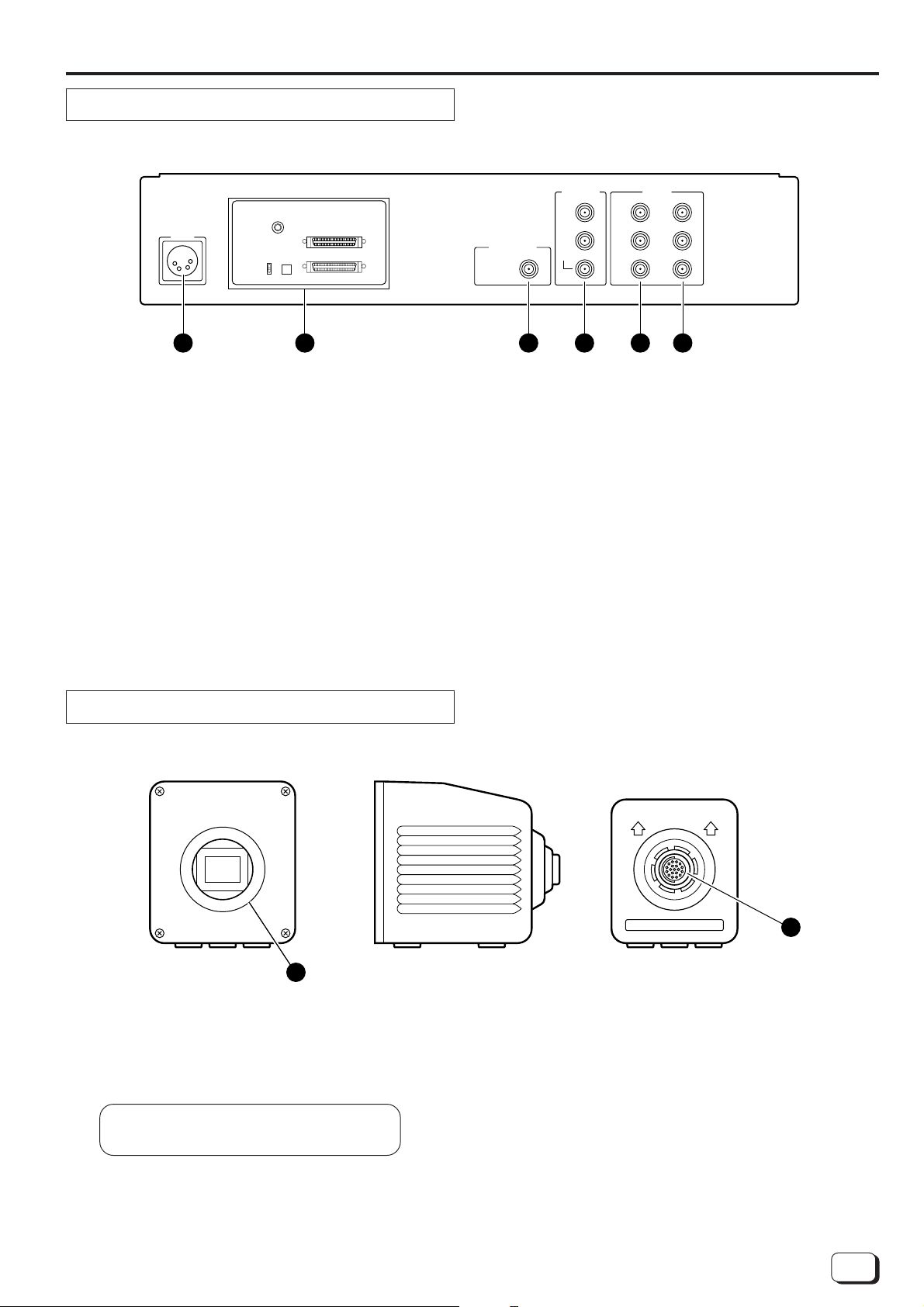
Camera control unit (rear panel)
DC-IN
Remote
Trigger
on
off
Termination SCSI ID
SCSI
12 3456
1 [DC INPUT] DC input connector
Input DC 12 V from the optional AA-V112E power
adaptor.
2 Cover for extension slot
Remove the cover to install an optional device in this
slot.
For the SCSI interface, refer to the instruction books
for the “Hardware” or “Driver Software”.
3 [GENLOCK INPUT] external sync signal
input jack
Reference signal input jack used to connect the
camera video output signal in sync with other
equipment such as an HD camera and switcher.
GEN-LOCK IN
VS/ C. SYNC
(
)
75Ω
SYNC OUT
HD
VD
C. SYNC
HD OUT
G
Y
B
B
P
RPR
4 [SYNC OUT] sync signal output jacks
Outputs HD (horizontal drive signal)/VD (vertical
drive signal)/C. SYNC.
5 [RGB OUT] RGB signal output jacks
Outputs RGB signals.
6 [Y, PB, PR OUT] video signal output jacks
Output Y, PB, PR signals.
When video signals are output to an HDTV monitor,
the screen will have a 16:9 aspect ratio, resulting in a
horizontally extended picture.
Camera head
(Front view)
1
1 Lens mount ring
• A special C mount is used. The form is for C
mount, however, the flange back length is 28.0
mm.
Ordinary C mount cannot be used.
The flange back length of an ordinary C
mount conversion lens is 17.526 mm.
(Side view)
(Rear view)
2
2 Camera cable connector
Connect the camera control unit with the optional
camera cable.
• To install a 1/2-inch bayonet mount conversion
lens, use the optional 1/2-inch bayonet mount
conversion adapter (GL-V62U) .
13
Page 14

Names of parts and their functions (continued)
Gain control section
1 GAIN switch
GAIN
NORMAL
AUTO MANUAL
ALC ALC + EEI
NORMAL
OVER UNDER
[AUTO]
The modes set with the 2 [AUTO MODE] switch can be
engaged for automatic gain adjustment. In this mode,
the [GAIN UP]/[GAIN DOWN] buttons are disabled.
[NORMAL]
Sets the gain to the reference gain [0 dB].
[MANUAL]
Select this mode to set the gain manually with the [GAIN
UP] and [GAIN DOWN] buttons.
2 AUTO MODE switch
GAIN
NORMAL
AUTO MANUAL
ALC ALC + EEI
NORMAL
OVER UNDER
[ALC]
Adjusts the gain automatically according to changes in
the brightness of the subject (auto sensitivity adjustment).
[ALC + EEI]
Automatically adjusts exposure by adjusting the gain
and shutter speed in combination according to changes
in the brightness of the subject.
3 AUTO GAIN switch
GAIN
NORMAL
AUTO MANUAL
ALC ALC + EEI
NORMAL
OVER UNDER
The [NORMAL] position is for standard auto sensitivity
adjustment. The [OVER] position adjusts the gain for
more brightness while the [UNDER] position adjusts the
gain for less brightness.
Effective only when the [GAIN] switch 1 is set to
[AUTO].
4 GAIN UP/GAIN DOWN buttons
GAIN
NORMAL
AUTO MANUAL
ALC ALC + EEI
NORMAL
OVER UNDER
[GAIN UP]
Each time this button is pressed, the gain increases by
1 dB.
[GAIN DOWN]
Each time this button is pressed, the gain decreases by
1 dB.
Effective only when the [GAIN] switch 1 is set to
[MANUAL]. Setting from -3 dB to +12 dB is possible.
14
Page 15

Shutter control section
SHUTTER
ON
V.SCAN
OFF
1 SHUTTER switch
SHUTTER
OFF
ON
V.SCAN
SHUTTER switch 1 and
SHUTTER [UP]/[DOWN] buttons 2
●When the SHUTTER switch 1 is set to [ON]
• Press the SHUTTER [UP] button 2 to decrease the
shutter speed.
• Press the SHUTTER [DOWN] button 2 to increase
the shutter speed.
Shutter speeds from 1/2000 to 1/30 sec. are avail-
able.
Usually shutter speed is not stored. If you want to
store it, set the shutter speed and then, switch a
cycle of change from [ON] to [OFF] of the 1 MENU
switch on page 16 in spite of the initial position.
●When the SHUTTER switch 1 is set to [OFF]
The shutter speed is fixed at 1/60 sec.
●When the SHUTTER switch 1 is set to [V. SCAN]
Set the shutter speed to match the scanning speed of
a computer monitor. When shooting a monitor, fineadjust the shutter speed to eliminate bright and dark
bars running horizontally. When the shutter speed is
faster than 1/60 sec., it is possible to fine adjust it with
the SHUTTER [UP]/[DOWN] buttons 2.
2 SHUTTER UP/DOWN buttons
Flicker-free mode
Prevents flickering caused by fluorescent lighting in a
50-Hz area.
When the shutter speed is set to 1/100 sec. (Flicker-free
mode), flickering is eliminated.
• When looking at the picture on the monitor during
the use of the electronic shutter, the movement of
the subject may appear discontinuous. This
phenomenon occurs because the picture for
1/2000 sec. is taken out every 1/60 sec.
(e.g.: Shutter speed of 1/2000 sec.)
• When the shutter speed is set to 1/2000 sec., the
charge storage time of the CCD image sensing
device is reduced to approx. 1/32. As a result, the
sensitivity is 1/32 that for the ordinary normal mode
(1/60 sec.) and the light is insufficient.
When shooting, increase the illumination by a
factor of 32 or open the lens iris by 5 if sufficient
light is available to obtain the optimum exposure.
• As the shutter speed in the V. SCAN mode is not
displayed, set the speed by viewing the picture so
that a stable picture can be obtained.
When the SHUTTER switch 1 is set to [OFF] or
the gain control section is set to [ALC+EEI], the
SHUTTER [UP]/[DOWN] buttons 2 have no effect.
At-a-glance sensitivity range chart (relationship between gain, iris value and shutter)
8 16 32 62.5 125 250 500 1000 2000 4000 8000 16000 32000 64000 128000 256000
ALC (1/60s)
ALC + EEI (1/60s)
ALC + EEI (1/30s)
+12dB
1/60s
+12dB
1/60s
+6dB
1/30s
+6dB
0dB
1/60s
+6dB
1/60s
0dB
1/30s
–4dB
1/60s
1/60s
0dB
0dB
0dB
1/60s
1/120s
0dB
0dB
1/60s
1/120s
F1.4 F2 F2.8 F4 F5.6 F8 F11
0dB
1/240s
1/480s
0dB
0dB
1/240s
1/480s
ALC (1/60s)
ALC + EEI (1/60s)
ALC + EEI (1/30s)
0dB
1/960s
0dB
1/960s
0dB
1/1920s
0dB
1/1920s
+12dB
1/60s
+12dB
1/60s
+6dB
1/30s
0dB
1/2000s
0dB
1/2000s
+6dB
1/60s
+6dB
1/60s
0dB
1/30s
0dB
1/60s
0dB
1/60s
0dB
1/60s
–4dB
1/60s
0dB
1/120s
0dB
1/120s
0dB
1/240s
0dB
1/240s
0dB
1/480s
0dB
1/480s
0dB
1/960s
0dB
1/960s
0dB
1/1920s
0dB
1/1920s
0dB
1/2000s
0dB
1/2000s
15
Page 16

Names of parts and their functions (continued)
White balance control section
1 WHITE BALANCE switch
[AUTO]
When set to this position, the camera is automatically
set to a pre-adjusted white balance.
R
2 SET switch
WHITE BALANCE
SET.
AUTO
B
WHITE BALANCE
SET.
AUTO
MANUAL
MANUAL
PRESET
3200K 5600K
FINE ADJ.RB
PRESET
3200K 5600K
Use the [SET] switch 2 to automatically readjust the
white balance.
[MANUAL]
Set to this position to adjust the white balance manually
with the [R]/[B] volume controls 3.
[PRESET]
Set to this position to set the white balance adjusted
using 3200K and 5600K light sources or the white
balance preset by a technician.
3200K and 5600K can be switched with the [3200K/
5600K] switch 4.
● If white balance adjustment has not been performed, adjust it by referring to the "Basic operation".
● In all [AUTO] and [PRESET] modes, red and blue
can be fine-adjusted with the [ADJ R] and [ADJ B]
volume controls 5 for FINE ADJ.
R
B
FINE ADJ.RB
3 R/B volume controls 4 3200K/5600K switch
SET.
R
WHITE BALANCE
MANUAL
AUTO
PRESET
3200K 5600K
B
FINE ADJ.RB
SET.
R
WHITE BALANCE
MANUAL
AUTO
B
5 ADJ R/ADJ B volume controls
PRESET
3200K 5600K
FINE ADJ.RB
16
Page 17

Mode control section
MODE
CAMERA TEST SG
POSI NEGA
ON OFF
BAR
FREEZE
DATE & TIME
MODE
CAMERA TEST SG
POSI NEGA
ON OFF
BAR
FREEZE
DATE & TIME
1 SOURCE switch
MODE
BAR
CAMERA TEST SG
FREEZE
POSI NEGA
DATE & TIME
ON OFF
[CAMERA]
Outputs signals from the camera to the monitor.
[BAR]
Outputs an internal colour bar signal from the unit to the
monitor.
[TEST SG]
Outputs an internal 100% WHITE square screen from
the unit to the monitor.
Use to adjust for 100% WHITE and the aspect ratio of
the monitor.
2 FREEZE button
Press the FREEZE button to engage the Field Still mode
and press it again to restore the normal mode.
The status is shown by the LED at the left of the
FREEZE button.
LED lit : Field still
LED extinguished : Normal use
3 POSI/NEGA switch
MODE
BAR
CAMERA TEST SG
FREEZE
POSI NEGA
DATE & TIME
ON OFF
[POSI]
Set to this position for ordinary operation.
[NEGA]
Outputs inverted red, blue and green signals from the
camera to the monitor.
4 DATE & TIME switch
[ON]
The date and time are shown in the upper right corner of
the screen.
[OFF]
The date and time are not shown.
17
Page 18

Names of parts and their functions (continued)
Menu control section
1 MENU switch
MENU
ON OFF
[ON]
The menu is displayed on the screen.
Select a menu item with the CURSOR button 2.
[OFF]
The menu is not displayed.
Menu settings will be stored in memory when this
switch is set to [OFF]. When you finish menu
2 CURSOR button
• The mark (•) on the left of the menu item indicates that
the item is selected.
• An up arrow (↑) or down arrow (↓) on the left of a
menu item indicates that items can be selected with
the [UP]/[DOWN] CURSOR buttons 2.
• A right arrow (→) or left arrow (←) on the right of a
menu item indicates that items can be selected with
the [LEFT]/[RIGHT] CURSOR buttons 2.
setting, be sure to set this button to [OFF] before
turning the power off.
The menu of this unit consists of three screens of PAGE 1 to 3.
MENU
ON OFF
■ MENU-PAGE 1
[AUXILIARY] menu
Functions of selected items are described below.
Selected items
MESSAGE
GAIN/SHUT
OFF
W. B. NAME
The message input with MESSAGE EDIT in
the [START] menu on MENU-PAGE 3 is shown
in the upper left corner of the screen.
The GAIN value and SHUTTER value are
shown in the upper left corner of the screen.
No indication
"AUTO WHITE BALANCE", "MANUAL WHITE
BALANCE", "PRESET 3200K", "PRESET
5600K" or the setting made by a technician are
shown when the [WHITE BALANCE] switch or
the [PRESET W. B.] menu is used.
[PRESET W. B.] menu
Use to select one of the preset white balance settings
(3200K, 5600K, or custom setting preset by a technician).
When the [WHITE BALANCE] switch is set to [PRESET], use the [LEFT]/[RIGHT] button to select 3200K,
5600K, or the custom preset value. Select 3200K or
5600K with the [3200K/5600K] switch.
Functions
[GAMMA] menu
Select a gamma correction value or no gamma correction.
Selected items Gamma
0.45 γ = 0.45
0.48 γ = 0.48
OFF No gamma correction (γ = 1.0)
[APERTURE] menu
Select the contour compensation value or no contour
compensation.
The leftmost setting on the minus side is for no contour
compensation. Compensation values are selectable in 8
steps.
[M. BLACK] menu
Select the master black (setup) value.
4 steps in the ± direction (about 2% shift/step) with the
center value standing for no setup.
[EEI] menu
Select whether or not to use the 1/30-sec. shutter speed
when automatic sensitivity compensation (ALC+EEI) is
used.
Selected items Shutter speeds
1/30 1/30 sec. is used.
1/60 1/30 sec. is not used.
[PAGE] menu
Switch menu PAGE 1 to PAGE 3 with the CURSOR
[LEFT]/[RIGHT] buttons.
18
Page 19

■ MENU-PAGE 2
[DATE] menu
Set the date.
Use the [LEFT]/[RIGHT] buttons to select the part of the
date to be changed (the numbers will blink). Use the
[UP]/[DOWN] buttons to set the new value.
[TIME] menu
Set the time.
Use the [LEFT]/[RIGHT] buttons to select the part of the
time to be changed (the numbers will blink). Use the
[UP]/[DOWN] buttons to set the new value.
[DATE FORM] menu
Change the date display format.
Use the [LEFT]/[RIGHT] buttons to select one of three
formats (year, month, day/day, month, year/month, day,
year). The date displays change in the following order:
year, month, day day, month, year month, day, year
[IRIS ZONE] menu
Change the size of the zone where automatic sensitivity
compensation (ALC, ALC+EEI) is performed.
Select from [LARGE], [MEDIUM], [SMALL] or
[V.STRIPE] with the [LEFT]/[RIGHT] buttons.
[IRIS DET.] menu
Select the level detection method for automatic sensitivity compensation (ALC, ALC+EEI) from peak detection
(P), average detection (A) or both. Use the [LEFT]/
[RIGHT] buttons to select from 9 different levels. Peak
detection is at the far left, while average detection is at
the far right. The 7 levels in between can be used for
combinations of peak detection and average detection.
[GENLOCK] menu
Use the [LEFT]/[RIGHT] buttons to adjust the horizontal
phase for the external sync signal. Phase can be
adjusted in 9 steps. Each time the button is pressed,
the phase is shifted by 34 ns. Pressing the button 10
times (340 ns), moves the indication by one graduation.
Adjustment up to 2.6 µs is possible.
[PAGE] menu
Switch menu PAGE 1 to PAGE 3 with the CURSOR
[LEFT]/[RIGHT] buttons.
■ MENU-PAGE 3
Use this menu to edit the message which will be shown
in the upper left corner of the screen.
• The message is shown when [MESSAGE] is selected
in MENU-PAGE 1's [AUXILIARY] menu.
• The message can include up to 22 alphanumeric
characters.
Selectable characters include A to Z, 0 to 9, ., :, -, /,
and space.
[START] menu
1 When [START] is selected, the right arrow (→) and
left arrow (←) together with "FIRST" and "LAST" are
shown.
2 The RIGHT/LEFT buttons function as described
below.
[RIGHT] : The first character of the message can be
edited.
[LEFT] : The last character of the message can be
edited.
3 Once you start editing, the buttons function as
described below.
[UP]/[DOWN] : Selects the characters.
[LEFT]/[RIGHT] : Moves the cursor.
[CLEAR] menu
Use this menu to delete the message. When [CLEAR] is
selected, the right arrow (→) and "EXECUTE" are
shown.
Press the [RIGHT] button. The down arrow (↓) and
"OK", and the up arrow (↑) and "CANCEL" are shown.
To delete the message, press the [DOWN] button. To
cancel the operation, press the [UP] button. The right
arrow (→) and "EXECUTE" indications are restored.
[PAGE] menu
Switch menu PAGE 1 to PAGE 3 with the CURSOR
[LEFT]/[RIGHT] buttons.
19
Page 20

Preparation
Installing a lens
This unit is not provided with a lens.
A special C mount type lens with flange back of 28.0 mm
can be used with no adapter. To use a 1/2" bayonet
mount type lens, an optional adapter (GL-V62U) is
required.
• Consult your lens dealer for information on installing and using your lens.
• Make sure the lens is screwed all the way in.
Otherwise, back focus cannot be obtained.
Reference
For your reference, examples of lenses that can be used
with the adapter are listed in the table below.
1/2" bayonet mount type lens
Manufacturer
Fujinon
Lens type
MSF10B
MSF75B
MS8X12B
MSF20B
MSF35B
Installing the camera control unit (when installing in a rack)
The camera control unit is provided with screw holes on
its side panels to allow installation in an EIA 19" rack.
Inner member
Inner member
1.
Remove the screws securing the rubber feet and
detach the rubber feet (four positions).
2.
Install the inner members for the slide rails on the
side panels of this unit.
3.
Install the outer members for the slide rails on the
rack. Slide the unit into the rack.
Slide rails from the following manufacturer can be
used.
Model name
C-305-20
Manufacturer's name
Japan Acuride Co., Ltd.
508 mm (20')
• For information on the installation of the outer
members and rack, consult the slide rail manufacturer or your dealer.
CAMERA
GAIN SHUTTER WHITE BALANCE MENUMODE
CAMERA CONTROL UNIT DZ-VCA1SE
Slide length
PUSH OPEN
POWER
ON
OFFIO
t = 3 mm
6.5 mm
9.8 mm
6 screws with a diameter of 4 mm
and a length of less than 6 mm
Inner member installation
44
6-M4
56.6 111.1 114.3
3
Inner member installation
hole position dimensions
(Unit: mm)
20
Screw hole size
Page 21

Before shooting
Setting the switches for white balance adjustment
To ensure a clear picture with correct colour tones, the
back focus and white balance must be adjusted prior to
shooting.
Check your connections before making any adjustments. With a monitor connected, set the camera
control unit's switches as shown below.
WHITE BALANCE switch → “AUTO”
SHUTTER switch → “OFF”
AUTO MANUAL
ALC ALC + EEI
NORMAL
OVER UNDER
GAIN
NORMAL
SHUTTER WHITE BALANCE MENUMODE
OFF SET.
ON
V.SCAN
When setting is complete, shoot a test subject.
Adjust the lens focus and check the picture on the
monitor.
Back focus adjustment
MANUAL
AUTO
PRESET
R
B
– In the function box –
White balance must be adjusted beforehand each
time you shoot.
Be sure to check the colour tone of the monitor using the
BAR signal before adjusting white balance.
If the monitor’s colour tone is incorrect, it may not be
possible to accurately adjust the white balance.
3200K 5600K
FINE ADJ.RB
SOURCE switch → “CAMERA”
BAR
CAMERA
FREEZE
POSI NEGA
DATE & TIME
ON OFF
TEST SG
ON OFF
To adjust the back focus, refer to the instruction manual
provided with the lens you are using.
Back focus adjustment is required only when the
lens is installed. No further adjustment is necessary.
21
Page 22

Basic operation
White balance adjustment
1 White balance adjustment (auto)
SET switch WHITE BALANCE switch
WHITE BALANCE
SET.
R
AUTO
B
MANUAL
PRESET
3200K 5600K
FINE ADJ.RB
While referring to the monitor, shoot a white subject
(such as a wall or sheet of paper) in full screen under
the same lighting conditions as those that will exist
during the actual shoot.
Set the WHITE BALANCE switch to [AUTO].
Hold the [SET] switch to the right. [AUTO WHITE] will
blink in the upper left corner of the monitor screen.
When white balance adjustment is complete, this
indication changes to [AUTO WHITE OK].
For further fine adjustment, use the [ADJ R]/[ADJ B]
volume controls for FINE ADJ.
If the indication in the upper left corner of the
monitor screen does not change to [AUTO WHITE
OK], white balance has not been completely adjusted.
Check the following points, then retry auto white
balance adjustment.
1. Is the light insufficient?
Adjust the lighting.
2. Did you shoot a coloured subject?
Shoot a white subject.
2 White balance adjustment (manual)
WHITE BALANCE switch
WHITE BALANCE
SET.
R
AUTO
B
MANUAL
PRESET
3200K 5600K
FINE ADJ.RB
R/B volume control
3 White balance adjustment (preset)
3200K/5600K switch
WHITE BALANCE switch
WHITE BALANCE
SET.
AUTO
MANUAL
PRESET
3200K 5600K
Connect a measuring instrument such as a waveform
monitor to the video signal output jacks and adjust the
white balance while watching the waveform.
First, set the WHITE BALANCE switch to [MANUAL].
Adjust the PB, PR output amplitudes to the minimum with
the [R]/[B] volume controls.
Adjust the PR with the [R] volume control and the PB with
the [B] volume control.
If a measuring instrument is not available, adjust the
picture on the monitor screen until it is white. In this
case, high-precision white balance cannot be
obtained.
Set the WHITE BALANCE switch to [PRESET].
When a halogen lamp is used as a light source, check
the MENU-PAGE 1's [PRESET W.B.] menu, and set the
[3200K/5600K] switch to 3200K. If a light source similar
to sunlight is used, set this switch to 5600K.
For further fine adjustment, use the [ADJ R]/[ADJ B]
volume controls for FINE ADJ.
22
R
B
FINE ADJ.RB
ADJ R/ADJ B volume controls
Page 23

Connectors
1 Input/output connector on the camera head
8 19
9
2
10
3
11
4
12
2 Input/output connector on the CCU
Pin
Nos.
1
2
3
18
7
17
1
6
16
5
15
1413
4
5
6
7
8
9
0
Pin
Nos.
Signals
Clock output
GND
Control signal input
Control signal input
Sync signal input
Sync signal input
Video signal output
GND
Video signal output
GND
Signals
Pin
Nos.
q
w
e
r
t
y
u
i
o
Pin
Nos.
Signals
Video signal output
GND
Video signal output
GND
15 V input
5 V input
GND
-8.5 V input
-5 V input
Signals
3 DC input connector
1 2 3 4
17 18 19 20
1
3
2
1
Clock input
2
GND
3
Control signal output
4
1098765
161514131211
Pin Nos.
4
Control signal output
5
Sync signal output
6
Sync signal output
7
Video signal input
8
GND
9
Video signal input
0
GND
1
2
3
4
GND
NC
NC
+12 V input
Signals
q
Video signal input
w
GND
e
Video signal input
r
GND
t
15 V output
y
5 V output
u
GND
i
-8.5 V output
o
-5 V output
p
NC
23
Page 24

Micro HD camera system component list
■HD camera system
Trade name Model name Organization
Micro HD camera
AC power adapter
Isolation transformer
Camera cable
Camera cable
Microscope adapter
1/2 inch bayonet conversion adapter
Endoscope adapter
Endoscope zoom adapter
HD monitor
W-VHS VCR
Cart
ZIP drive
DZ-VCA1SE
AA-V112E
AA-V31E
VC-V3
VC-V10
GL-V61U
GL-V62U
GL-V63U
GL-V64U
HV-M2000V
SR-W7MAE
(VS5402.X/VS6300.X)
(Z250S)
Camera head
Camera Control Unit
Insulating rubber covers x 3
Handle
Power code for UK
Power code for EC Continent
Power code for W-VHS
SCSI card
SCSI cable
Power code for ZIP drive
Monitor cable
AC power adapter
Power code for AC adapter
Isolation transformer, Plug retainer brackets,
Cover plates, Torx head screws
Camera cable 3 m
Camera cable 10 m
Microscope adapter
1/2 inch bayonet conversion adapter
Endoscope adapter
Endoscope zoom adapter
HD monitor, Power code
W-VHS VCR, Power code
Cart
ZIP drive, AC power adapter for ZIP drive
Voltage Current Frequency
Micro HD camera DC 12 V DC 1.3 A
AC power adapter in AC 120 V AC 0.8 A (max) 50 Hz
out DC 12 V DC 3.0 A
Isolation transformer in AC 230 V AC 1.5 A 50 Hz
out AC 120 V AC 2.7 A
HD monitor AC 120 V AC 1.6 A 50/60 Hz
W-VHS VCR
ZIP drive AC adapter in
AC 110 V – 240 V
AC 100 V – 240 V
out DC 5 V DC 1.0 A
AC 0.7 A 50/60 Hz
AC 0.2 A 50/60 Hz
24
Page 25

Specifications
* Design and specifications subject to change without notice.
Camera head section
■Image sensing device : 1/3-inch IT-CCD (410,000 pixels)
■Shooting system : 4-CCD new dual green system
■Colour separation optical system: 1/3 type F1.4 3-colour separation prism
■Number of effective pixels : 768 (horizontal) x 494 (vertical), 380,000 pixels
■Camera output : 19 pins
■Lens mount : Special mount (C mount form, flange back: 28.0 mm)
■Dimensions : Camera head; 59 (W) x 70 (H) x 79 (D) mm (2-3/8” x 2-13/16” x 3-1/8”)
(not including insulating rubber covers)
■Weight : Camera head; 230 g (0.51 lbs.) (not including insulating rubber covers)
■Classification : Type BF
Camera control unit section
■Number of scanning lines : 1125 (980 effective)
■Scanning system : 2:1 interlace
■Scanning frequency : 33.75 kHz (horizontal), 60 Hz (vertical)
■Aspect ratio : 4:3
■Horizontal resolution (center) : More than 800 TV lines (Y signal)
■Vertical resolution (center) : More than 650 TV lines (Y signal)
■S/N : 52 dB
■Sensitivity : F5.6, 2000 lx
■Minimum subject illuminance : 10 lx (F1.6 + 12 dB, 1/30 shutter, 50% level)
■Sync system : Internal sync/external sync
■External sync signal input : Composite video signal of 1 Vp-p or composite sync signal of ±0.3 Vp-p, 75 ohms, BNC x 1
■Colour bar : Full colour bar
■Contour correction : Horizontal dual-edged (9-step variable)
Vertical dual-edged (9-step variable)
■Electronic shutter speed : 1/30 s, 1/60 s (normal), 1/100 s (flicker-free), 1/175 s, 1/250 s, 1/375 s, 1/500 s, 1/1000 s,
1/2000 s
■Video output
• R/G/B signal : 0.7 Vp-p, 75 ohms for each (no sync), BNC connector x 3 (one for each)
B/PR Y : 1 Vp-p, 75 ohms (including sync)
• Y/P
B : 0.7 Vp-p, 75 ohms (including sync)
P
R : 0.7 Vp-p, 75 ohms (including sync)
P
• Sync signal : HD; BNC x 1 (TTL)
VD, BNC x 1 (TTL)
C. SYNC; BNC x 1
(±0.3 Vp-p, 75 ohms, compliant with HDTV standard ITU-R Rec. 709)
■SCSI Interface : Half pitch D-sub 50 pin (female) x 2
■Camera input : 20 pins
■Date indication : Menu system
1) Year, month, day
2) Day, month, year
3) Month, day, year
■Time indication : Menu system,
hour: minute: second
■Power supply : DC 12 V, 1.3 A XLR 4 pins, AA-V112E AC power adaptor
When using this unit for medical purposes, be absolutely sure to use the
separately sold AA-V31E isolation transformer.
■Power consumption : 18 W
■Operating environment : +5°C to +35°C (41°F to 95°F), 35 – 75%
■Allowable storage environment : –20°C to +50°C (–4°F to 122°F), 35 – 80%
■Dimensions : 430 (W) x 93 (H) x 322 (D) mm
(16-15/16" x 3-11/16" x 12-11/16")
(excluding the handle for rack mounting)
■Weight : 4.9 kg (10.8 lbs.)
■Accessories : Handle set x 1
■Supplied documentation : Instruction manual x 1
Warrantee card x 1
Service center information x 1
25
Page 26

AC power adapter AA-V112E
■Manufacturer : Victor Company of Japan
Limited
■Input : AC 120 V 50 Hz, MAX. 0.8 A
■Output : 12 V DC
■Accessories : AC inlet cable (Hospital
Grade) x 1
■Classification : Class I
3.0 A
Isolation transformer AA-V31E
■Manufacturer : Victor Company of Japan
Limited
■Classification : CLASS I
■Input : AC 230 V 1.50 A
50 Hz
■Output : AC 120 V 2.7 A
50 Hz
■Accessories :
Plug retainer bracket x 4
Torx head screw x 8
Cover plate x 4
Flat washer x 3
Split locking washer x 3
HD monitor HV-M2000V
■Power requirements : AC 120 V 50/60 Hz
■Power consumption : 1.6 A
■ Dimensions : 476 mm (W) x 407.5 mm (H) x
529 mm (D)
■ Weight: : 31.6 kg
■ Accessory : AC power cord (2.4 m) x 1
TECHNICAL AND SERVICE
ASSIST ANCE
JVC offers technical and customer service assistance.
Please contact us at the following address.
JVC PROFESSIONAL PRODUCTS (UK) LIMITED
ULLswater House, Kendel Avenue, London W3 OXA,
United Kingdom
TEL: (0181) 896-6000
FAX: (0181) 896-6060
JVC PROFESSIONAL PRODUCTS GmbH
Grüner Weg 10, 61169 Fiedberg/Hessen, Germany
TEL: (06031) 6050
FAX: (06031) 605180
Symbols indicated on this equipment have the
following meanings.
Attention, consult ACCOMPANYING
DOCUMENTS
Alternating current
W-VHS VCR SR-W7MAE
■Power requirements : AC 110 – 240 V 50/60 Hz
■ Dimensions : 476 mm (W) x 148 mm (H) x
366 mm (D)
■ Weight: : 10 kg
■ Accessories : Power cord x 1
Remote control unit x 1
Cleaning tape x 1
Mobile video cart VS5402.X/VS6300.X
■ Dimensions
VS5402.X : 500 mm (W) x 1428 mm (H) x
490 mm (D)
VS6300.X : 600 mm (W) x 1108 mm (H) x
490 mm (D)
■ Load capacity
• Basic-framework total additional load
: 225 kg
• Shelf : 50 kg
• Drawer : 20 kg
• Pull-out shelf : 20 kg
■ Monitor shelf
• Load capacity : 35 kg
Zip drive Z250S
■ AC adapter for ZIP drive
• Input : AC 100 – 2 40 V
50/60 Hz
• Output : 5 V DC
1.0 A
Direct current
Off (power: disconnection from the mains)
On (power: connection to the mains)
TYPE BF APPLIED PART
Equipotential terminal
Video output
26
Page 27

■ Outer dimensions
Camera head
70
Camera control unit
26 26
(Front)
(Inside panel)
67.5
CAMERA
36
31.5
3 8.5
59
29
0.5
13
(Front)
29
482
430
GAIN SHUTTER WHITE BALANCE MENUMODE
289.4
SHUTTER WHITE BALANCE MENUMODE
OFF SET.
ON
V.SCAN
MANUAL
AUTO
B
R
ALC ALC + EEI
NORMAL
OVER UNDER
GAIN
NORMAL
AUTO MANUAL
78.5
72
60
34
PRESET
3200K 5600K
FINE ADJ.RB
(Side)
(Bottom)
CAMERA CONTROL UNIT DZ-VCA1SE
BAR
CAMERA
TEST SG
ON OFF
FREEZE
POSI NEGA
DATE & TIME
ON OFF
6.5
(Rear)
PUSH OPEN
POWER
ON
OFFIO
55.2
7.25
8.05
88
5
(Rear)
(Side)
427.5
SYNC OUT
HD OUT
GBY
B
P
RPR
DC-IN
Remote
Trigger
on
off
Termination SCSI ID
SCSI
VS /C . SYNC
GEN-LOCK IN
(
)
75Ω
HD
VD
C. SYNC
335.6
30023 12.8
(Unit: mm)
27
Page 28

JVC PROFESSIONAL PRODUCTS (UK) LIMITED
ULLswater House, Kendel Avenue, London W3 OXA, United Kingdom
JVC PROFESSIONAL PRODUCTS GmbH
Grüner Weg 10, 61169 Fiedberg/Hessen, Germany
COPYRIGHT © 2000 VICTOR COMPANY OF JAPAN, LTD.
E
Printed in Japan
0200IYV*ID*SW1
Page 29

LYT0469-001B
Instructions
ISOLATION TRANSFORMER AA-V31E
Dear Customer,
Thank you for purchasing the JVC Isolation Transformer
AA-V31E. Before use, please read the safety precautions
below to ensure safe use of your new Isolation
Transformer.
For Customer Use:
Enter below the Model No. and Serial No. which
are located on the rear of the cabinet. Retain this
information for future reference.
1 Breaker/power switch
Model No.
Serial No.
2 Power lamp (Green LED)
3 Ground indicator lamp (Red LED)
Safety precautions
WARNING:
To prevent fire or shock hazard, DO NOT expose this
unit to rain or moisture.
WARNING:
To prevent electrical shock, DO NOT remove the
Isolation Transformer cover.
WARNING:
The Isolation Transformer’s “thumb screw” groundstud is to be used to connect items such as static
discharge floor mats or telephone switch grounds that
contain a single conductor ground.
Any equipment that is not connected via a 3-conductor power cord will be floating above ground. If the
end user elects to provide additional grounds, they
must be
tied to the ground-stud.
INTRODUCTION
JVC Isolation Transformer AA-V31E is designed to protect
electronic microprocessor-based systems from problems
caused by power line disturbances.
The model you have purchased is designed for use
together with the AC Power Adapter AA-V112E and
MICRO HD CAMERA DZ-VCA1SE for medical applications.
INSPECTION
Remove the Isolation Transformer from the shipping
container and inspect it for shipping damage. Do not
install or operate the product if it appears to be damaged
in any way. If damaged, notify the carrier and seller
immediately.
ENVIRONMENTAL CONSIDERATIONS
This Isolation Transformer has environmental requirements similar to other medical devices. It has been
designed for indoor use only, in areas where it will not be
exposed to excessive dust or moisture. Make certain that
there is adequate air flow around the unit. Do not place
objects on top of or near the unit which could obstruct the
air vents. For installation, please refer to the MICRO HD
CAMERA DZ-VCA1SE Instruction Book.
WARNING:
This equipment is not sterilized.
SIZING INFORMATION AND INSTALLATION PROCEDURE
The name plate on the rear panel lists the Isolation
Transformer voltage and current ratings. Observe that the
input current rating is not exceeded when connecting
equipment. Ask that installation be performed by a JVC
authorized dealer.
Page 30

OPERATING INSTRUCTIONS
SPECIFICATIONS
Turn all load equipment ON.
Turn the Isolation Transformer circuit breaker ON.
Observe that the front-panel green LED is illuminated.
Observe that the red LED (marked ) is not illuminated
(place the Isolation Transformer on a non-grounded
surface such as a carpet, wooden table, or magazine for
this test).
CAUTION:
If the red LED is continuously flashing, the wall receptacle
(powering the Isolation Transformer) is not connected to
the system safety ground. Immediately contact an electrician to correct the wiring discrepancy.
IMPORTANT NOTE:
The red LED is not intended to test general wiring integrity. Hot-neutral reversal, neutral-ground reversal, and/or
other wiring errors will not illuminate the red LED.
Once the Isolation Transformer has been properly installed per the installation instructions, the Isolation
Transformer and load equipment can be turned ON/OFF
via the Isolation Transformer circuit breaker (and if not
externally circuit breaker equipped, via the panel circuit
breaker).
Symbols indicated on this equipment have the following meanings.
Attention, consult ACCOMPANYING
DOCUMENTS
Isolation Transformer
■Manufacturer : Victor Company of Japan Limited
■Model No. : AA-V31E
■Classification : CLASS I
■Input : 230 V AC 1.50 A 50 Hz
■Output : 120 V AC 2.7 A 50 Hz
Accessories
■Plug retainer bracket x 4
■Torx head screw x 11
■Cover plate x 3
■Flat washer x 4
■Split locking washer x 11
■Input cord holder x 1
TECHNICAL AND SERVICE ASSIST ANCE
JVC offers technical and customer service assistance.
Please contact us at the following address.
JVC PROFESSIONAL PRODUCTS (UK) LIMITED
ULLswater House, Kendel Avenue, London W3 OXA,
United Kingdom
TEL: (0181) 896-6000
FAX: (0181) 896-6060
JVC PROFESSIONAL PRODUCTS GmbH
Grüner Weg 10, 61169 Fiedberg/Hessen, Germany
TEL: (06031) 6050
FAX: (06031) 605180
Dangerous voltage
Alternating current
Off (power: disconnection from the mains)
On (power: connection to the mains)
Equipotential terminal
0200IYV*ID*VP
Page 31

LYT0468-002B
Instructions
AC POWER ADAPTER AA-V112E
Dear Customer,
Thank you for purchasing the JVC AC Power Adapter
AA-V112E. Before use, please read the safety precautions below to ensure safe use of your new AC Power
Adapter.
AC Power Adapter
For Customer Use:
Enter below the Model No. and Serial No. which
are located on the bottom of the cabinet. Retain
this information for future reference.
Model No.
Serial No.
INTRODUCTION
The model you have purchased is designed for use
together with the Isolation Transformer AA-V31E and
MICRO HD CAMERA DZ-VCA1SE for medical applications.
Safety precautions
WARNING:
To prevent fire or shock hazard, DO NOT expose this
equipment to rain or moisture.
WARNING:
This equipment is not sterilized.
INSPECTION
Remove the AC Power Adapter from the shipping container and inspect it for shipping damage. Do not use the
product if it appears to be damaged in any way. If damaged, notify the carrier and seller immediately.
ENVIRONMENTAL CONSIDERATIONS
This AC Power Adapter has environmental requirements
similar to other medical devices. It has been designed for
indoor use only, in areas where it will not be exposed to
excessive dust or moisture. Make certain that there is
adequate air flow around the unit. Do not place objects on
top of or near the unit which could obstruct the air vents.
For usage, please refer to the MICRO HD CAMERA DZVCA1SE Instruction Book.
SIZING INFORMATION AND INSTALLATION PROCEDURE
The name plate on the top panel lists the AC Power
Adapter voltage and current ratings. Observe that the
input current rating is not exceeded when connecting
equipment. Ask that installation be performed by a JVC
authorized dealer.
Page 32

AA-V112E INFORMATION
SPECIFICATIONS
This information contains instructions on using AA-V112E.
Please read it to use properly.
The way of use and instructions
• AA-V112E is inlet type AC power adapter. For the input
cord, be sure to use the provided AC inlet cable.
• Rated input voltage is AC120V continuously.
• Inside this AC Power Adapter, there is a high voltage
part. Never disassemble this.
Symbols indicated on this equipment have the following meanings.
Attention, consult ACCOMPANYING
DOCUMENTS
Alternating current
Direct current
AC Power Adapter
■Manufacturer : Victor Company of Japan Limited
■Model No. : AA-V1 12E
■Input : AC 120 V 50 Hz
MAX. 0.8 A
■Output : 12 V DC 3.0 A
TECHNICAL AND SERVICE ASSIST ANCE
JVC offers technical and customer service assistance.
Please contact us at the following address.
JVC PROFESSIONAL PRODUCTS (UK) LIMITED
ULLswater House, Kendel Avenue, London W3 OXA,
United Kingdom
TEL: (0181) 896-6000
FAX: (0181) 896-6060
JVC PROFESSIONAL PRODUCTS GmbH
Grüner Weg 10, 61169 Fiedberg/Hessen, Germany
TEL: (06031) 6050
FAX: (06031) 605180
0200IYV*ID*VP
Page 33

EN
How to assemble covers
1. Turn the front part of endscpe
adapter counterclockwise and
take off them.
2. Insert cover(1) and assemle
them.
3. Insert the camera cable
connector of the cammera
head side to cover(2) and
assemble them.
When connecting camera to an endoscope
1) Before using the endoscope, always be sure to sterilize the endoscope
video adapter, the camera head, the camera cable, and covers.
2) When using the endoscope, always be sure to assemble covers
according to the instruction of the left side of this sheet.
Cover(1)
Endoscope adapter
(fixed lens)GL-V63U
(zoom lens)GL-V64U
Cover(2)
Cover(3)
SCSI board
built in CCU
CCU(Camera Control Unit)
DZ-VCA1SE
AC Power
adaptor
AA-V112 E
ZIP drive
(Z250S)
4:3 HD Monitor
HV-M2000V
W-VHS
SR-W7MAE
4. Insert the camera cable
connector of CCU side to
cover(3) and assemble them.
Mobile video cart
iTD GmbH VS5402.X
Isolation transformer
AA-V31E
LYT0468-005A
0200IYV
*ID*
SW1
Page 34

System Operating Procedure
Check the operation of the system according to the procedure described below.
1. Connect the camera cable to the CCU.
• Turn off the CCU before connecting or disconnecting the camera cable.
2. Plug the power cord of the Isolation Transformer into a power outlet.
3. Turn on the Isolation Transformer.
Confirm that the red LED is not flashing.
If the red LED is flashing, do not use the unit. Improve the grounding of the power outlet.
4. Turn on the ZIP drive.
5. After the ZIP drive power stabilizes (about five seconds), turn on the CCU.
If the CCU is turned on before the ZIP drive power stabilizes, a communications error may be
generated.
Load a ZIP disk into the ZIP drive, press the FREEZE button on the CCU’s front panel, and confirm
that still images are loaded properly.
If the green LED on the ZIP drive lights, the unit is operating normally.
6. Turn on the W-VHS unit.
Load a W-VHS tape into the unit and confirm that the unit is able to record.
7. Turn on the monitor.
Confirm that the MODE selector on the CCU’s front panel is set to “CAMERA” and confirm that the
image that is being shot by the camera appears on the monitor.
8. Operate each component in accordance with their operating procedures.
Note: Connections should be made only by JVC service personnel or other qualified service
personnel. Do not disconnect or alter any connections.
LYT0468-006A
Page 35

Page 36

Page 37

Page 38

Page 39

Page 40

Page 41

Page 42

 Loading...