

Page 1
SERVICE MANUAL
COMPACT COMPONENT SYSTEM
MB616<Rev.002>20084SERVICE MANUAL
DX-U10A, DX-U10US, DX-U10UX, DX-U10UG,
DX-U10UN, DX-U8US, DX-U8UX, DX-U8UG,
DX-U8UN, DX-U6US, DX-U6UX, DX-U6UG,
DX-U6UN, DX-U10UH
SP-DXU10W SP-DXU10W
SP-DXU10S SP-DXU10S
COPYRIGHT © 2008 Victor Company of Japan, Limited
SP-DXU10F SP-DXU10F
SP-DXU10W
Lead free solder used in the board (material : Sn-Ag-Cu, melting point : 219 Centigrade)
Lead free solder used in the board (material : Sn-Cu, melting point : 230 Centigrade)
CA-DXU10
SUPER VIDEO
CA-DXU6
SP-DXU6F SP-DXU6F
SP-DXU10C
SP-DXU10W
SP-DXU8S
SUPER VIDEO
CA-DXU8
SP-DXU10F
SP-DXU8S
SP-DXU10F
TABLE OF CONTENTS
1 PRECAUTION. . . . . . . . . . . . . . . . . . . . . . . . . . . . . . . . . . . . . . . . . . . . . . . . . . . . . . . . . . . . . . . . . . . . . . . . . 1-4
2 SPECIFIC SERVICE INSTRUCTIONS. . . . . . . . . . . . . . . . . . . . . . . . . . . . . . . . . . . . . . . . . . . . . . . . . . . . . . 1-7
3 DISASSEMBLY . . . . . . . . . . . . . . . . . . . . . . . . . . . . . . . . . . . . . . . . . . . . . . . . . . . . . . . . . . . . . . . . . . . . . . . 1-8
4 ADJUSTMENT . . . . . . . . . . . . . . . . . . . . . . . . . . . . . . . . . . . . . . . . . . . . . . . . . . . . . . . . . . . . . . . . . . . . . . . 1-34
5 TROUBLESHOOTING . . . . . . . . . . . . . . . . . . . . . . . . . . . . . . . . . . . . . . . . . . . . . . . . . . . . . . . . . . . . . . . . . 1-35
SP-DXU10C
COPYRIGHT © 2008 Victor Company of Japan, Limited
No.MB616<Rev.002>
2008/4
Page 2
SPECIFICATION
DX-U10/DX-U8
Amplifier section Output Power FRONT SPEAKERS 150 W per channel, min. RMS, driven into 4 Ω at 1 kHz with
CENTER SPEAKER CA-DXU10 140 W per channel, min. RMS, driven into 6 Ω at 1 kHz with
CA-DXU8 50 W per channel, min. RMS, driven into 6 Ω at 1 kHz with no
SURROUND SPEAKERS CA-DXU10 130 W per channel, min. RMS, driven into 6 Ω at 1 kHz with
CA-DXU8 50 W per channel, min. RMS, driven into 6 Ω at 1 kHz with no
SUBWOOFERS 150 W, min. RMS, driven into 4 Ω at 63 Hz with no more than
Digital output OPTICAL DIGITAL OUTPUT -21 dBm to -15 dBm (660 nm ±30 nm)
Digital input USB memory
Audio input sensitivity/
Impedance
VIDEO OUT Color system PAL/PAL PROG/NTSC/NTSC PROG selectable
Speaker Terminals 4 Ω - 16 Ω (front speakers/subwoofers)
Tuner section FM tuning range 87.50 MHz - 108.00 MHz
AM (MW) tuning range 531 kHz - 1 710 kHz (at 9 kHz)
AM (MW) tuning range for Saudi Arabia 531 kHz to 1 602 kHz (9 kHz)
Disc/file player section Region codes Middle East: 2
Playable disc DVD Video/DVD Audio/CD/VCD/SVCD
Playable file MP3, WMA, WAV, JPEG, MPEG-1, MPEG-2, ASF, DivX for-
Dynamic range 80 dB
Horizontal resolution 500 lines
Wow and flutter Immeasurable
USB storage section USB specification Compatible with USB 2.0 Full Speed
Compatible device Mass Storage Class
Compatible file system FAT16, FAT32
Bus power supply 5 V / 500 mA
Cassette deck section Frequency response: Normal (type I) 50 Hz - 14 000 Hz
Wow and flutter 0.15% (WRMS)
General Power requirement AC 110 V / AC 127 V / AC 220 V / AC 230 V - AC 240 V ,
Power requirement: For Australia AC 240 V , 50 Hz
Power consumption CA-DXU10 300 W (at operation) / 22 W (on standby)
Dimensions (W/H/D) (approx.) 185 mm × 460 mm × 370 mm
Mass (approx.) CA-DXU10 11.5 kg
AUX(STEREO) 400 mV/47 kΩ
MIC1/MIC 2 3.0 mV/50 kΩ
VIDEO (composite) 1 V(p-p)/75 Ω
S-VIDEO Y (luminance) : 1 V(p-p)/75 Ω
COMPONENT
(Interlace/Progressive)
CA-DXU8 270 W (at operation) / 21 W (on standby)
CA-DXU8 11.4 kg
no more than 10% total harmonic distortion.
no more than 10% total harmonic distortion.
more than 10% total harmonic distortion.
no more than 10% total harmonic distortion.
more than 10% total harmonic distortion.
10% total harmonic distortion.
C (chrominance, burst) : PAL : 0.3 V(p-p)/75 Ω
C (chrominance, burst) : NTSC : 0.286 V(p-p)/75 Ω
(Y) : 1 V(p-p)/75 Ω
(PB/PR) : 0.7 V(p-p)/75 Ω
6 Ω - 16 Ω (surround/center speakers)
530 kHz - 1 710 kHz (at 10 kHz)
530 kHz to 1 600 kHz (10 kHz)
South East Asia: 3
Central and South America, Australia: 4
CD-R/CD-RW (CD/VCD/SVCD/MP3/WMA/WAV/JPEG/
MPEG-1/MPEG-2/ASF/DivX format)
CD-ROM (MP3/WMA/WAV/JPEG/MPEG-1/MPEG-2/ASF/
DivX format)
DVD-R/-RW (DVD-VR/DVD Video/DVD Audio/MP3/WMA/
WAV/JPEG/MPEG-1/MPEG-2/ASF/DivX format)
+R/+RW (DVD Video/DVD Audio/MP3/WMA/WAV/JPEG/
MPEG-1/MPEG-2/ASF/DivX format)
DVD-ROM (DVD Video/MP3/WMA/WAV/JPEG/MPEG-1/
MPEG-2/ASF/DivX format)
mat
(adjustable with the voltage selector), 50 Hz / 60 Hz
Measured at 1 kHz, with tape recording signal 400 mV
Design and specifications are subject to change without notice.
1-2 (No.MB616<Rev.002>)
Page 3
DX-U6
Amplifier section Output Power FRONT SPEAKERS 150 W per channel, min. RMS, driven into 4 Ω at 1 kHz with no more
than 10% total harmonic distortion.
SUBWOOFER 150 W, min. RMS, driven into 4 Ω at 63 Hz with no more than 10% t otal
harmonic distortion.
Digital output OPTICAL DIGITAL OUTPUT -21 dBm to -15 dBm (660 nm ±30 nm)
Digital input USB memory
Audio input sensitivity/
Impedance
VIDEO OUT Color system PAL/PAL PROG/NTSC/NTSC PROG selectable
Speaker Terminals 4 Ω - 16 Ω (main speakers/subwoofer)
Tuner section FM tuning range 87.50 MHz - 108.00 MHz
AM (MW) tuning range 531 kHz - 1 710 kHz (at 9 kHz)
AM (MW) tuning range: For Saudi Arabia 531 kHz to 1 602 kHz (9 kHz)
Disc/file player section Region codes Middle East: 2
Playable disc DVD Video/DVD Audio/CD/VCD/SVCD
Playable file MP3, WMA, WAV, JPEG, MPE G-1, MPEG -2, ASF , DivX form at
Dynamic range 80 dB
Horizontal resolution 500 lines
Wow and flutter Immeasurable
USB storage section USB specification Compatible with USB 2.0 Full Speed
Compatible device Mass Storage Class
Compatible file system FAT16, FAT32
Bus power supply 5 V / 500 mA
Cassette deck section Frequency response: Normal (type I) 50 Hz - 14 000 Hz
Wow and flutter 0.15% (WRMS)
General Power requirement AC 110 V / AC 127 V / AC 220 V / AC 230 V - AC 240 V , (adjustable
Power requirement: For Australia AC 240 V , 50 Hz
Power consumption 200 W (at operation)
Dimensions (W/H/D) (approx.) 185 mm × 460 mm × 370 mm
Mass (approx.) 10.5 kg
AUX 400 mV/47 kΩ
MIC1/MIC2 3.0 mV/50 kΩ
VIDEO (composite) 1 V(p-p)/75 Ω
S-VIDEO Y (luminance) : 1 V(p-p)/75 Ω
C (chrominance, burst) : PAL : 0.3 V(p-p)/75 Ω
C (chrominance, burst) : NTSC : 0.286 V(p-p)/75 Ω
COMPONENT
(Interlace/Progressive)
(Y) : 1 V(p-p)/75 Ω
(PB/PR) : 0.7 V(p-p)/75 Ω
16 Ω - 32 Ω (matrix surround speakers)
530 kHz - 1 710 kHz (at 10 kHz)
530 kHz to 1 600 kHz (10 kHz)
South East Asia: 3
Central and South America, Australia: 4
CD-R/CD-RW (CD/VCD/SVCD/MP3/WMA/WAV/JPEG/MPEG-1/
MPEG-2/ASF/DivX format)
CD-ROM (MP3/WMA/WAV/JPE G/MPEG-1/MPEG-2/ASF/DivX for-
mat)
DVD-R/-RW (D VD -VR/DVD Video/DVD Audio/MP3/WMA/WAV/
JPEG/MPEG- 1 /MPEG-2/ASF /D ivX format)
+R/+RW (DVD Video/DVD Audio/MP3/WMA/WAV/JPEG/MPEG -1/
MPEG-2/ASF/DivX format)
DVD-ROM (DVD Video/MP3/WMA/WAV/JPEG/MPEG-1/MPEG-2/
ASF/DivX format)
with the voltage selector), 50 Hz / 60 Hz
19 W (on standby)
Measured at 1 kHz, with tape recording signal 400 mV
Design and specifications are subject to change without notice.
(No.MB616<Rev.002>)1-3
Page 4
SECTION 1
PRECAUTION
1.1 Safety Precautions
(1) This design of this product contains special hardware and
many circuits an d compo nents spec ially f or saf ety purpos es. For continued protection, no changes should be made
to the original design unless authorized in writing by the
manufacturer. Replacement parts must be identical to
those used in the original circuits. Services should be performed by qualified personnel only.
(2) Alterations of the design or circuitry of the product should
not be made. Any design alterations of the product should
not be made. Any design alterations or additions will void
the manufacturers warranty and will further relieve the
manufacture of respons ibility for p ersonal injury or p roperty
damage resulting therefro m.
(3) Many electrical and mechanical parts in the products have
special safety-related characteristics. These characteristics are often not eviden t from visu al inspec tion nor ca n the
protection afforded by the m necessaril y be obtained by using replacement compo nents rated for higher vo ltage, wattage, etc. Replacement parts which have these special
safety characteristics are identified in the Parts Lis t of Se rvice Manual. Electrical components having such features
are identified by shadin g on the schema tics and by ( ) on
the Parts List in the Servic e Manual. The use of a s ubstitute
replacement whic h d oe s not ha ve the same safety c ha rac teristics as the recommended replacement parts shown in
the Parts List of Service Manual may create shock, fire, or
other hazards.
(4) The leads in the products are routed and dressed with ties,
clamps, tubings, barri ers and the l ik e to b e se para ted from
live parts, high temperature parts, moving parts and/or
sharp edges for the prevention of electric shock and fire
hazard. When service is required, the original lead routing
and dress should be observed, and it should be confirmed
that they have been returned to normal, after reassembling.
(5) Leakage shock hazard testing
After reassembling the product, always perform an isolation check on the exposed metal parts of the product (antenna terminals, knobs, metal cabinet, screw heads,
headphone jack, co ntrol shaf ts, etc.) to be sure t he prod uct
is safe to operate w ithou t dange r of el ectric al sh ock.Do not
use a line isolation transformer during this check.
• Plug the AC line cord directly into the AC outlet. Using a
"Leakage Current Tes t er" , me as ure t he l eak ag e current
from each exposed metal pa rts of the cabine t, particula rly any exposed metal part having a return path to the
chassis, to a know n good earth ground. Any le akage current must not exceed 0.5mA AC (r.m.s.).
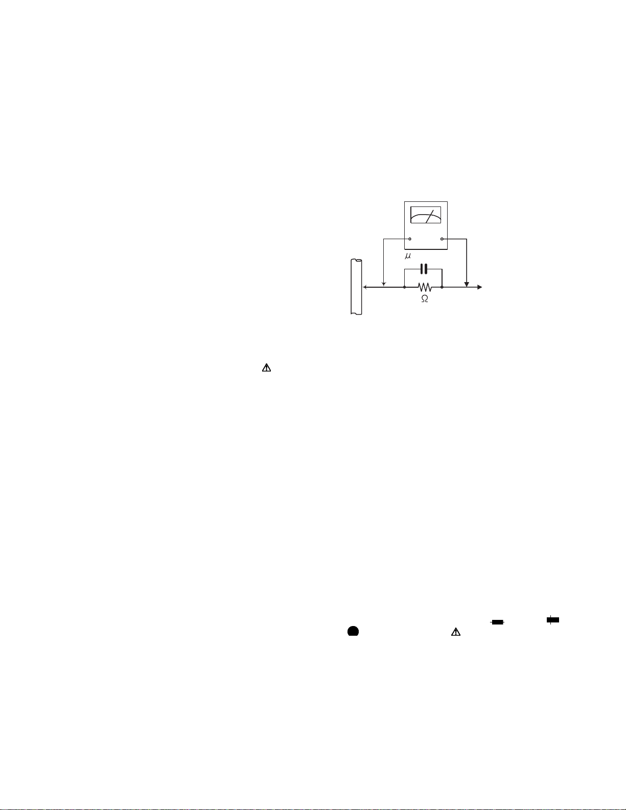
• Alternate check method
Plug the AC line cord directly into the AC outlet. Use an
AC voltmeter having, 1,000Ω per volt or more sensitivity
in the following mann er. C o nne ct a 1,50 0Ω 10W resistor
paralleled by a 0.15µF AC-type capacitor betw een an exposed metal part and a known good earth ground.
Measure the AC voltage across the resistor with the AC
voltmeter.
Move the resistor connection to each exposed metal
part, particularly any exposed metal part having a return
path to the chassis, and measure the AC voltage across
the resistor. Now, reverse the plug in the AC outlet and
repeat each measurement. Voltage measured any must
not exceed 0.75 V AC (r.m.s.). This corresponds to 0.5
mA AC (r.m.s.).
AC VOLTMETER
(Having 1000
ohms/volts,
or more sensitivity)
0.15 F AC TYPE
Place this
probe on
1500 10W
Good earth ground
1.2 Warning
(1) This equipment has been designed and manufactured to
meet international safety standards.
(2) It is the legal responsibility of the repairer to ensure that
these safety standards are maintained.
(3) Repairs must be made in accordance with the relevant
safety standards.
(4) It is essen tial that sa fety critic al com ponen ts ar e repl aced
by approved parts.
(5) If mains voltage selector is pro vided, ch eck set ting for loc al
voltage.
1.3 Caution
Burrs formed during molding ma y be left over on some parts
of the chassis.
Therefore, pay attention to such burrs in the case of preforming repair of this system.
1.4 Critical parts for safety
In regard with component parts appearing on the silk-screen
printed side (parts side) of the PWB di agra ms , the parts that are
printed over with black such as the resistor ( ), diode ( )
and ICP ( ) or identified by the " " mark nearby are critical
for safety. When replacing them, be sure to use the parts of the
same type and rating as specified by the manufacturer.
(This regulation dose not Except the J and C version)
each exposed
metal part.
1-4 (No.MB616<Rev.002>)
Page 5
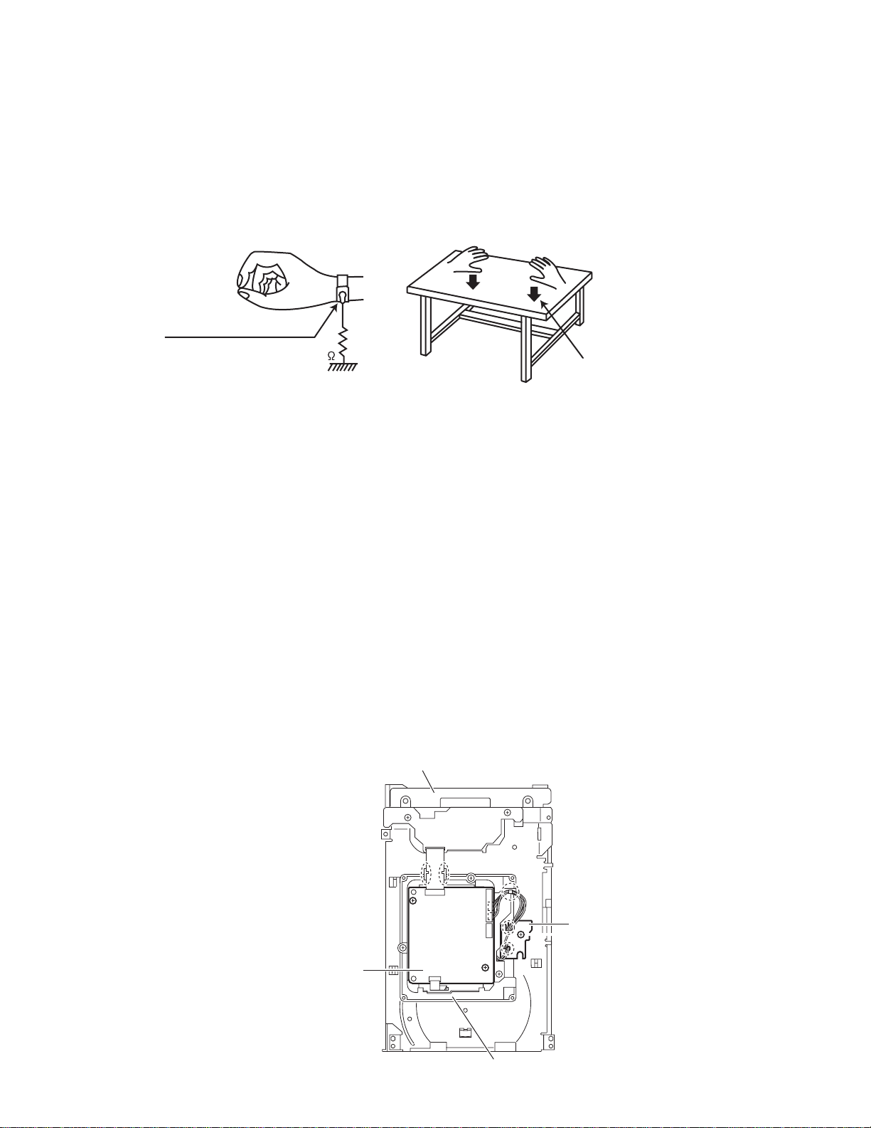
1.5 Preventing static electricity
Electrostatic discharge (ESD), w hi ch occurs w hen sta tic ele ct ricit y sto red i n the bod y, fa bric , etc. is discharged, ca n de stroy the laser
diode in the traverse unit (optical pickup). Take care to prevent this when performing repairs.
1.5.1 Grounding to prevent damage by static electricity
Static electricity in the work area can destroy the optical pickup (laser diode) in devices such as laser products.
Be careful to use proper grounding in the area where repairs are being performed.
(1) Ground the workbench
Ground the workbench by laying conductive material (such as a conductive sheet) or an iron plate over it before placing the
traverse unit (optical pickup) on it.
(2) Ground yourself
Use an anti-static wrist strap to release any static electricity built up in your body.
(caption)
Anti-static wrist strap
1M
Conductive material
(conductive sheet) or iron palate
(3) Handling the optical pickup
• In order to maintain quality during transport and before installation, both sides of the laser diode on the replacement optical
pickup are shorted. After replacement, return the shorted parts to their original condition.
(Refer to the text.)
• Do not use a tester to check the condition of th e laser dio de in the opt ical pi ckup. The tes ter's inte rnal power source ca n easily
destroy the laser diode.
1.6 Handling the traverse unit (optical pickup)
(1) Do not subject the traverse unit (optical pickup) to strong shocks, as it is a sensitive, complex unit.
(2) Cut off the shorted part of the flexible cable using nip pers, etc. afte r replacing th e optical pi ckup. For speci fic details, refe r to the
replacement procedure in th e t ext . R em ove the anti-static pin w he n re pla cing the traverse unit. Be c arefu l not to tak e to o l on g a
time when attaching it to the connector .
(3) Handle the flexible cable carefully as it may break when subjected to strong force.
(4) I t is not possible to adjust the semi-fixed resistor that adjusts the laser power. Do not turn it.
1.7 Attention when traverse unit is decomposed
*Please refer to "Disassembly method" in the text for the pickup unit.
• Apply solder to the short land sections before the card wire is disconnected from the connecto on the servo board. (If the card wire
is disconnected without applying solder, the pickup may be destroyed by static electricity.)
• In the assembly, be sure to remove solder from the short land sections after connecting the card wire.
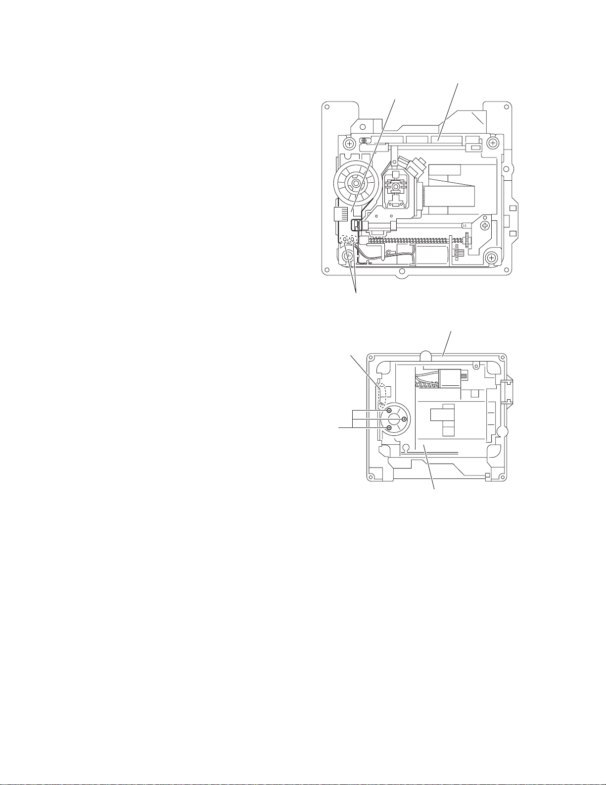
DVD changer mechanism assembly
DVD servo board
Switch board
DVD traverse mechanism assembly
(No.MB616<Rev.002>)1-5
Page 6
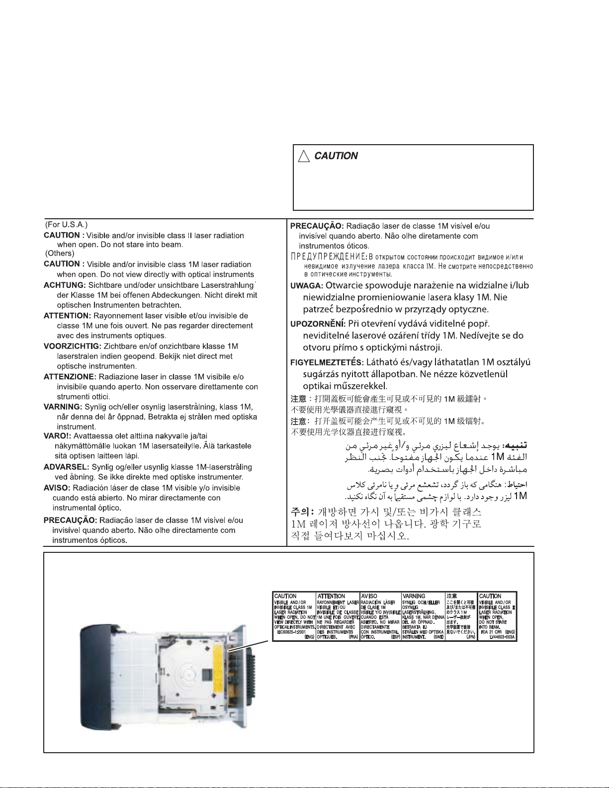
1.8 Important for laser products
1.CLASS 1 LASER PRODUCT
2.CAUTION :
(For U.S.A.) Visible and/or invisible class II laser radiation
when open. Do not stare into beam.
(Others) Visible and/or invisible class 1M laser radiation
when open. Do not view directly with optical instruments.
3.CAUTION : Visible and/or invisible laser radiation when
open and inter lock failed or defeated. Avoid direct
exposure to beam.
4.CAUTION : This laser product uses visible and/or invisible
laser radiation and is equipped with safety switches which
prevent emission of radiation when the drawer is open and
the safety interlocks have failed or are defeated. It is
dangerous to defeat the safety switches.
5.CAUTION : If safety switches malfunction, the laser is able
to function.
6.CAUTION : Use of controls, adjustments or performance of
procedures other than those specified here in may result in
hazardous radiation exposure.
!
Please use enough caution not to
see the beam directly or touch it
in case of an adjustment or operation
check.
REPRODUCTION AND POSITION OF LABELS and PRINT
WARNING LABEL and PRINT
1-6 (No.MB616<Rev.002>)
Page 7

SECTION 2
SPECIFIC SERVICE INSTRUCTIONS
This service manual does not describe SPECIFIC SERVICE INSTRUCTIONS.
(No.MB616<Rev.002>)1-7
Page 8
SECTION 3
A
DISASSEMBLY
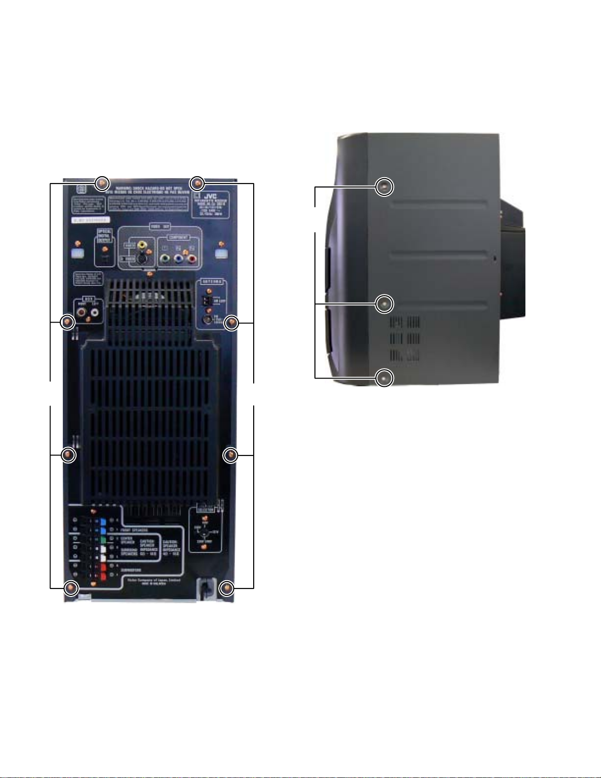
3.1 Main body (Using figures are DX-U10)
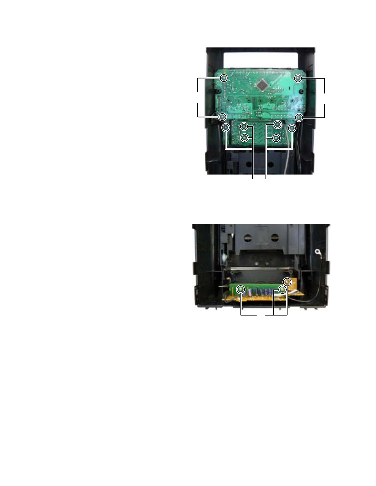
3.1.1 Removing the METAL COVER
(See Fig.1, 2)
(1) Remove the eight screws A attachi ng the METAL COVER.
(See Fig.1)
(2) Remove the six screws B attaching the both side of the
METAL COVER. (See Fig.2)
B
Fig.1
A
Fig.2
1-8 (No.MB616<Rev.002>)
Page 9
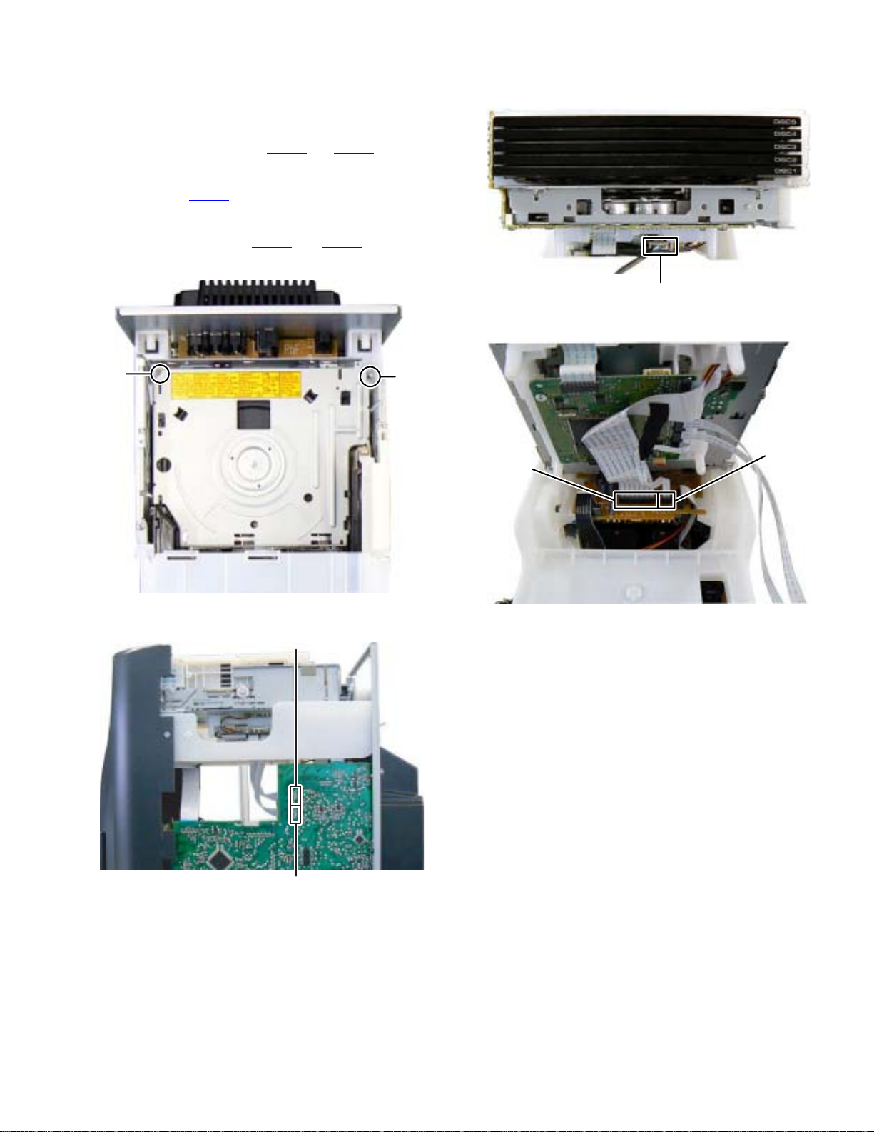
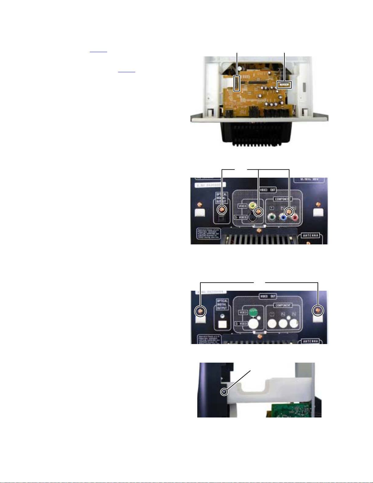
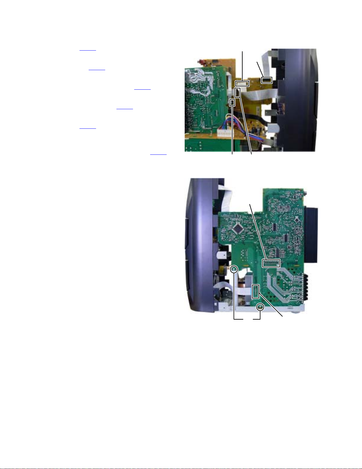
3.1.2 Removing the DVD CHANGER MECHANISM assembly
(See Fig.3 to 6)
(1) Remove the two screws C attaching the DVD MECHA-
NISM assembly. (See Fig.3)
(2) Disconnect the card wires from DVD MECHANISM assem-
bly connected to conne ctor CN800
BOARD assembly. (See Fig.4)
(3) Disconnect the connector wire from USB board connected
to connec tor CN811
Fig.5)
(4) Disconnect the card wires from DVD BOARD assembly
connected to connector CN921
board assembly. (See Fig.6)
of the DVD BOARD assembly. (See
and CN810 of the MAIN
and CN930 of the VIDEO
CN811
Fig.5
C
Fig.3
C
CN921
CN930
Fig.6
CN800
Fig.4
CN810
(No.MB616<Rev.002>)1-9
Page 10
3.1.3 Removing the VIDEO BOARD assembly
(See Fig.7, 8)
(1) Disconnect the card wire from MAIN BOARD assembly
connected to connector CN920 of the VIDEO BOARD assembly. (See Fig.7)
(2) Disconnect the card wi re from SURROUND AM P BOARD
assembly connected to connector CN931
BOARD assembly. (See Fig.7)
(3) Remove the three screws D attaching the VIDEO BOARD
assembly. (See Fig.8)
of the VIDEO
CN920 CN931
Fig.7
D
3.1.4 Removing the MECHA CHASSIS
(See Fig.9, 10)
(1) Remove the two screws E attaching the MECHA CHAS-
SIS. (See Fig.9)
(2) Remove the two screws F attaching the both side of
MECHA CHASSIS (See Fig.10)
Fig.8
E
Fig.9
F
Fig.10
1-10 (No.MB616<Rev.002>)
Page 11
3.1.5 Removing the REAR COVER with FAN
(See Fig.11, 12)
(1) Remove the One screw G attaching the REAR COVER.
(See Fig.11)
(2) Disengage six hooks a engaged REAR COVER. (See
Fig.11)
(3) Disconnect the connector wir e from FA N connected to con-
nector CN304
(See Fig.12)
of the SURROUND AMP BOARD assembly.
G
hook
a
hook
a
Fig.11
Fig.12
(No.MB616<Rev.002>)1-11
CN304
Page 12
3.1.6 Removing the TUNER PACK
(See Fig.13, 14)
(1) Disconnect the card wire from TUN ER PAC K connec ted to
connector CN750 of the MAIN BOARD assembly. (See
Fig. 13)
(2) Remove the two screws H attaching the TUNER PACK.
(See Fig.14)
CN750
Fig.13
H
Fig.14
1-12 (No.MB616<Rev.002>)
Page 13
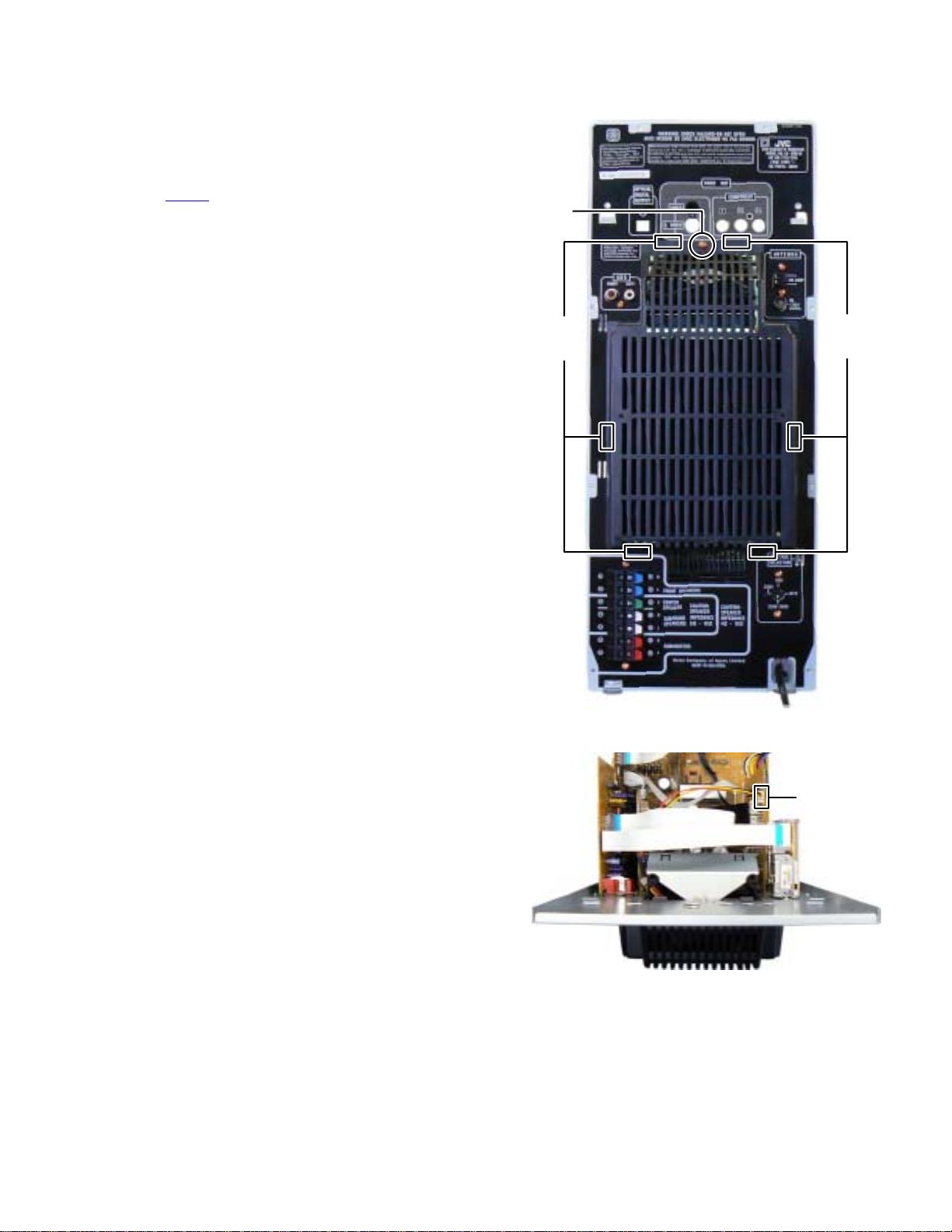
3.1.7 Removing the REAR PANEL
(See Fig.15, 16)
(1) Remove the four screws J attachi ng th e HEAT SINK by or-
der. (See Fig.15)
(2) Remove the five screws K attaching the REAR PANEL.
(See Fig.15)
(3) Disengage two hooks b engaged both side of the REAR
PANEL. (See Fig.16)
K
J
order 3 order 4
J
order 1 order 2
K
Fig.15
J
J
K
Fig.16
(No.MB616<Rev.002>)1-13
hook b
Page 14
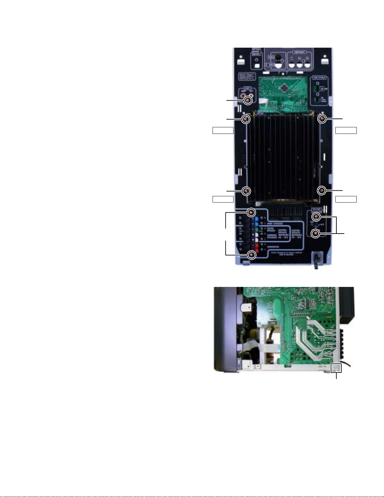
3.1.8 Removing the MAIN BOARD assembly
(See Fig.17, 18)
(1) Disconnect the card wire from FL BOARD assembly con-
nected to connector CN720 of the MAIN BOARD assembly. (See Fig.17)
(2) Disconnect the card wire from CASSETTE MECHANISM A
connected to connector CN730
sembly. (See Fig.17)
(3) Disconnect the card wire from SUBWOOFER AMP
BOARD assemb ly connected t o connector CN820
MAIN BOARD assembly. (See Fig.17)
(4) Disconnect the card wi re from SURROUND AM P BOARD
assembly connected to connector CN830
BOARD assembly. (See Fig.17)
(5) Disconnect the card wire from MIC BOAR D asse mbly c on-
nected to connector CN740
bly. (See Fig.18)
(6) Remove the two screws L attaching the MAIN BOARD as -
sembly. (See Fig.18)
(7) Disconnect the BOARD TO BOARD connector CN850
connected the MAIN BOAR D assembly and RE GULATOR
BOARD assembly. (See Fig.18)
of the MAIN BOARD as-
of the
of the MAIN
of the MAIN BOARD assem-
CN730
CN720
CN820 CN830
Fig.17
CN850
L
Fig.18
CN740
1-14 (No.MB616<Rev.002>)
Page 15
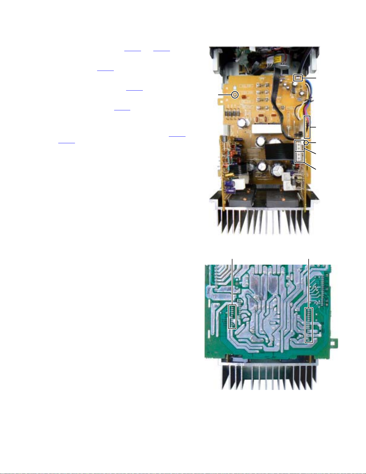
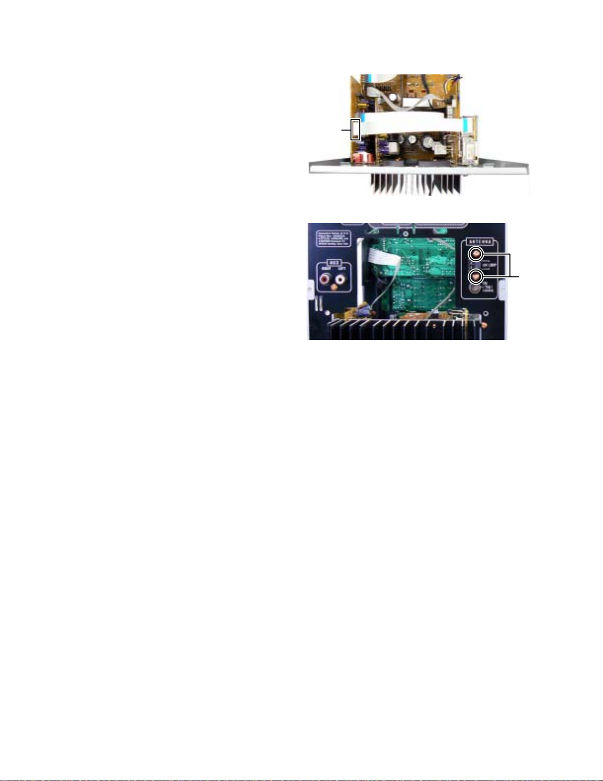
3.1.9 Removing the REGULATOR BOARD assembly
(See Fig.19, 20)
(1) Disconnect the card wire from REGULATOR BOARD as-
sembly connected to connector CN305
SURROUND AMP BOARD assembly. (See Fig.19)
(2) Disconnect the card wire from FL BOARD assembly con-
nected to connector CN207
assembly. (See Fig.19)
(3) Disconnect the connector wire from TRANS BOARD as-
sembly connected to connector CN201
TOR BOARD assembly. (See Fig.19)
(4) Disconnect the EARTH WIRE from TRANS BOARD as-
sembly connected to pin PP201
BOARD assembly. (See Fig.19)
(5) Remove the one screw M attaching the REGULATOR
BOARD assembly. (See Fig.19)
(6) Disconnect the BOARD TO BOARD connectors CN204
and CN205 connected to SURROUND AMP BOARD assembly and SUBWOOFER AMP BOARD assembly. (See
Fig.20)
of the REGULATO R BOARD
and CN306 of the
of the REGULA-
of the REGULATOR
CN207
M
CN201
PP201
CN306
CN305
Fig.19
CN204 CN205
Fig.20
(No.MB616<Rev.002>)1-15
Page 16
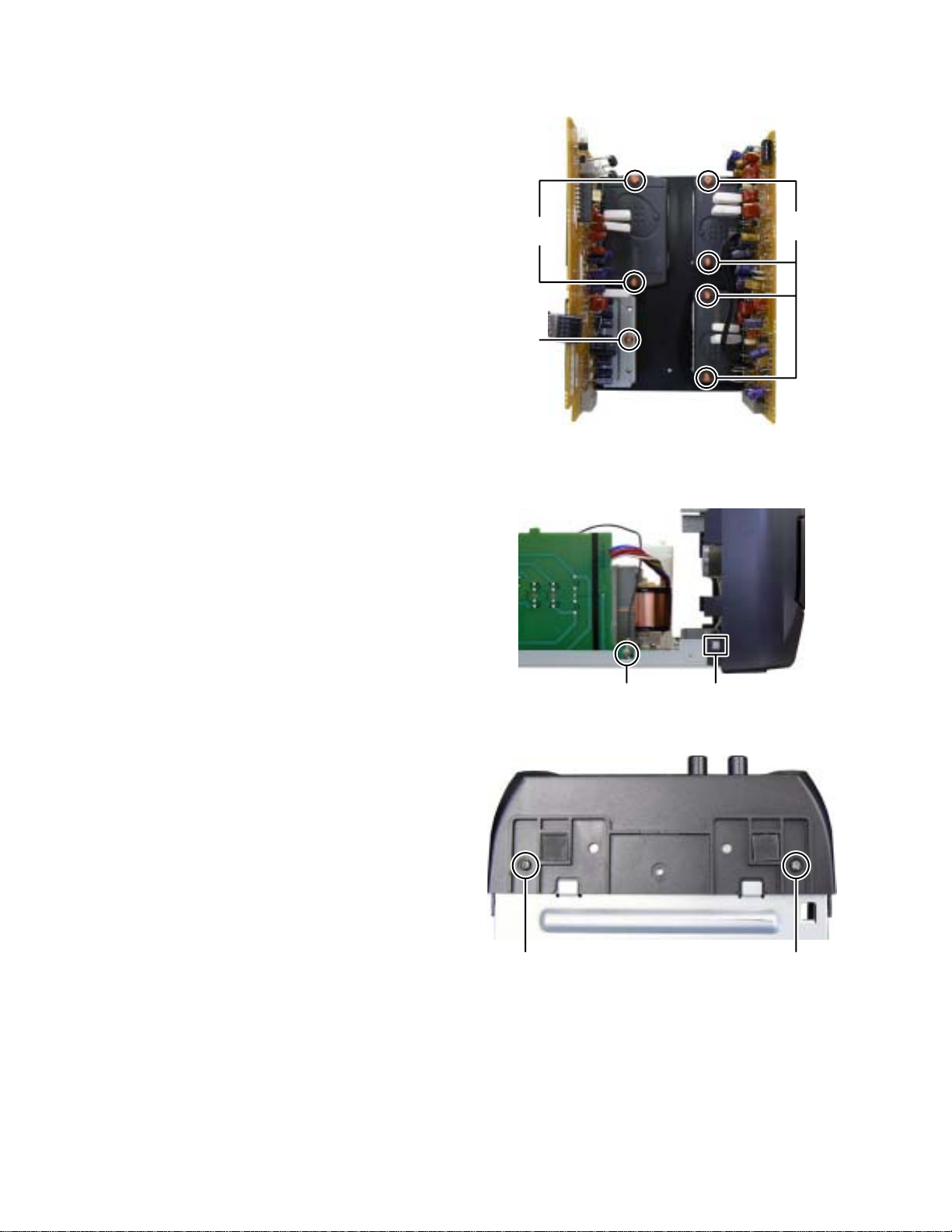
3.1.10 Removing the SURROUND AMP BOARD assembly
(See Fig.21)
(1) Remove the two screws N attaching the POWER AMP IC.
(2) Remove the one screw P attaching the IC BRACKET.
3.1.11 Removing the SUBWOOFER AMP BOARD assembly
(See Fig.21)
(1) Remove the four screws Q attaching the POWER AMP
ICs.
3.1.12 Removing the FRONT PANEL assembly
(See Fig.22, 23)
(1) Remove the one screw R attaching the EARTH WIRE from
MIC BOARD assembly. (See Fig.22)
(2) Remove the two screws S attaching the FRONT PANEL
assembly. (See Fig.23)
(3) Disengage two hooks c engaged both side of FRONT
PANEL assembly. (See Fig.22)
P
N
Q
Fig.21
R
Fig.22
hook c
SS
Fig.23
1-16 (No.MB616<Rev.002>)
Page 17
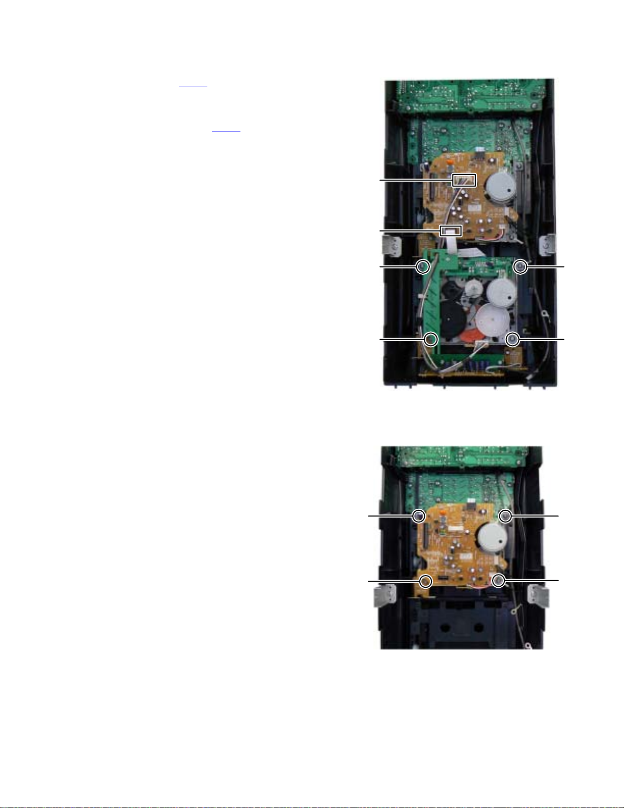
3.1.13 Removing the CASSETTE MECHANISM B
(SeeFig.24)
(1) Disconnect the card wire from CASSETTE MECHANISM B
connected to connector CN120
ANISM BOARD assembly of the CASSETTE MECHANISM A.
(2) Disconnect the connector wire from CASSETTE MECHA-
NISM B connected to connector CN200
MECHANISM BOARD assembly of the CASSETTE
MECHANISM A.
(3) Remove the four screws T attaching the CASSETTE
MECHANISM B.
of the CASSETTE MECH-
of the CASSETTE
CN200
CN210
3.1.14 Removing the CASSETTE MECHANISM A
(See Fig.25)
(1) Remove the four screws U attaching the CASSETTE
MECHANISM A.
T
T
TT
Fig.24
U
U
U
U
Fig.25
(No.MB616<Rev.002>)1-17
Page 18
3.1.15 Removing the FL BOARD assembly and SWITCH BOARD assembly
V
(See Fig.26)
(1) Remove the four screws V attaching the FL BOARD as-
sembly.
(2) Remove the six screws W attaching the SWITCH BOARD
assembly.
V
3.1.16 Removing the MIC BOARD assembly
(See Fig.27)
(1) Remove the two volume knobs.
(2) Remove the three screws X attaching the MIC BOARD as -
sembly.
WW
Fig.26
1-18 (No.MB616<Rev.002>)
X
Fig.27
Page 19
3.2 DVD changer mechanism assembly section
Remove the DVD changer mechanism assembly from the main body. (See "Removing the DVD changer mechanism assembly".)
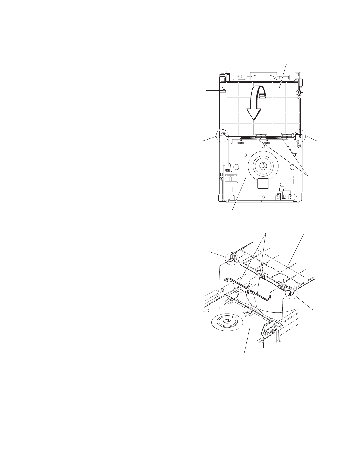
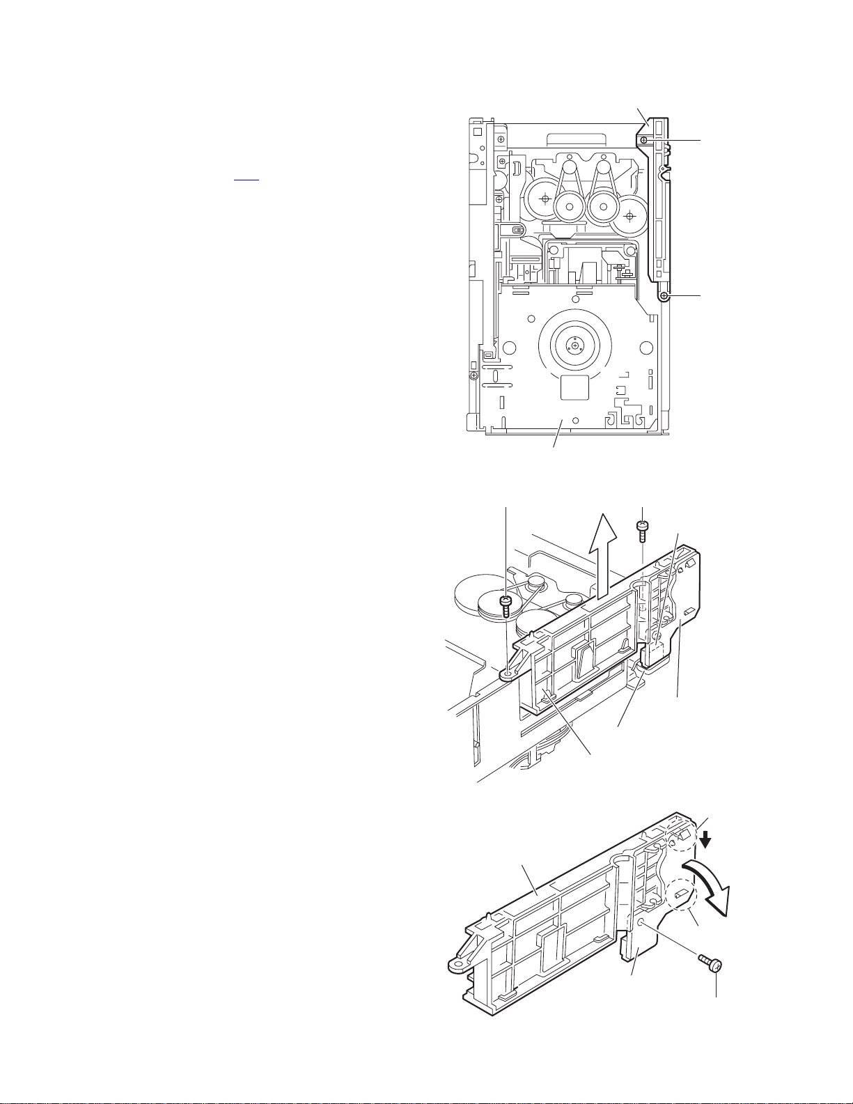
3.2.1 Removing the tray assemblies
(See Figs.1 to 5)
(1) From the top side of the main body, remove the two screws
A from the top cover and release the two joints a on the
both sides of the DVD changer mechanism assembly. (See
Figs.1 and 2.)
(2) Remove the two rods from the top cover and remove the
top cover from the lifter assembly. (See Figs.1 and 2.)
(3) Remove the open det. lever on the left side of the DVD
changer mechanism assembly. (See Fig.3.)
(4) From the right side of the DVD changer mechanism as-
sembly, draw out the tray a ssemblies to ward the f ront while
pushing th e part b of the side (R) assembly. (See Figs.4
and 5.)
Note:
The tray can be locked if all tray assemblies are attached.
(5) From the topside of the DVD changer mechanism assem-
bly, move the stopper tabs c in the direction of the arrow
and release them. Pull out the tray assemblies from the
DVD changer mechanism assembly. (See Fig. 5.)
Note:
Remove the tray assembly from top tray 5 in order.
Reference:
When reattaching the tray assembly, or when removing the
disc remaining inside, refer to another section "3.3.15 Taking
out the disc in the play mode".
A
a
Lifter assembly
Fig.1
Rods
Top cover
A
a
Rods
Top cover
a
a
Lifter assembly
Fig.2
(No.MB616<Rev.002>)1-19
Page 20
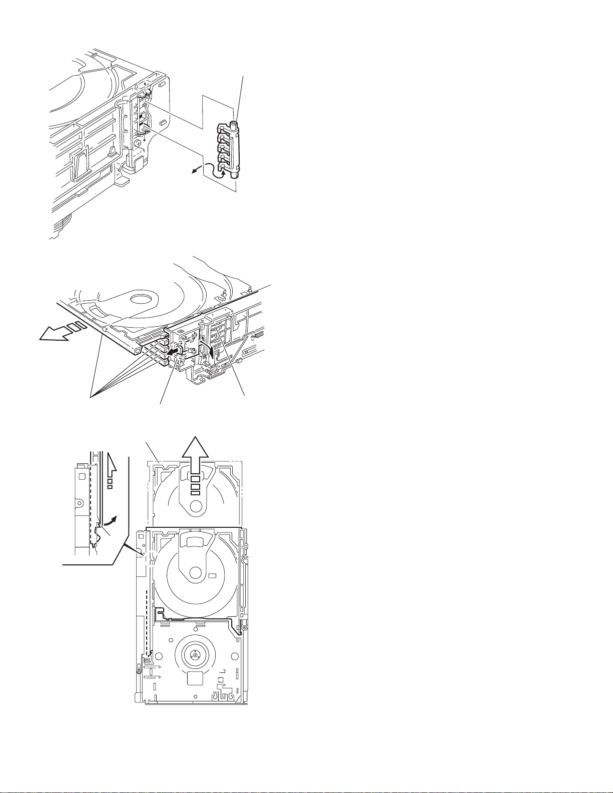
Fig.3
r
Open det. leve
Tray assemblies
c
b
Side(R) assembly
Fig.4
Tray assembly
1-20 (No.MB616<Rev.002>)
Fig.5
Page 21
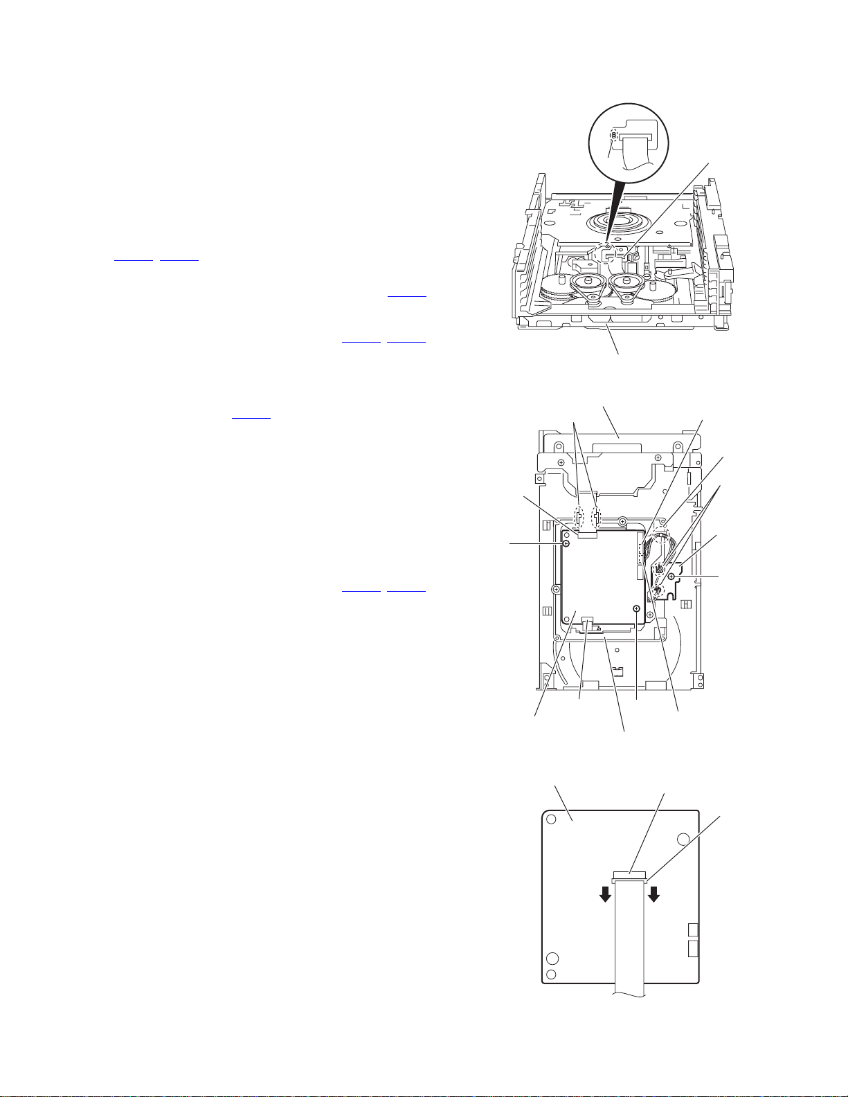
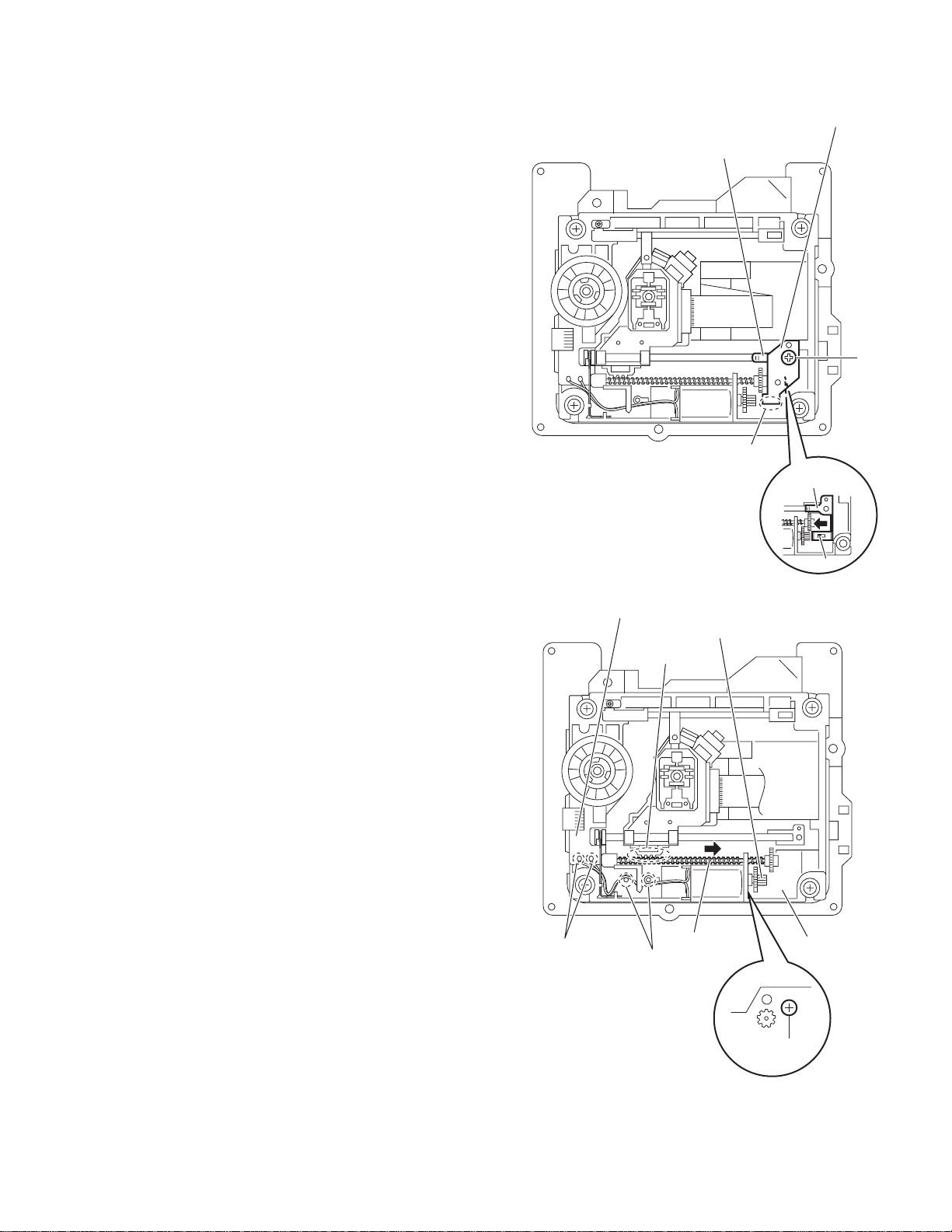
3.2.2 Removing the DVD servo board
(See Figs.6 to 8)
Caution:
Solder the short land sections d on the DVD pickup before disconnecting the card wire extending from the DVD pickup. If
you do not follow th is instruction, the DVD pic kup may be d amaged.
(1) From the topside of the DVD changer mechanism assem-
bly, solder the short land sections d on the DVD pick up.
(See Fig.6.)
(2) From the bottom side of the DVD changer mechanism as-
sembly, disconnect the card wire from the connectors
(CN201
Reference:
(3) Disconnect the wires from the conne ctors (CN452
on the DVD servo board. (See Fig.7.)
(4) Remove the two screws B attaching th e DV D servo board.
(See Fig.7.)
(5) From the reverse side of the DVD servo board, release the
lock of the connector CN101
and disconnect the card wire. (See Fig.8.)
Caution:
Unsolder the solder s from t he short lan d secti ons d af ter reassembling. (See Fig.6.)
3.2.3 Removing the switch board
(1) From the bottom side of the DVD changer mechanism as-
sembly, remove the screw C attac hing th e swi tch boa rd on
the DVD changer mechanism assembly.
(2) Disconnect the wires from the conne ctors (CN452
on the DVD servo board.
(3) Release the wires from the section f and remo ve the switch
board.
(4) Release the wires from the sections g and remove the
switch board.
Reference:
When reassembling, pass the wires thro ugh the secti ons (f, g)
as before.
, CN451) on the DVD servo board. (See Fig.7.)
When connecting the c ard w ir e to the connect or CN451
pass it through the sections e on the DVD traverse
mechanism assembly. (See Fig.7.)
, CN453)
in the direction of the arrow
(See Fig.7)
, CN453)
d
,
DVD changer mechanism assembly
Fig.6
DVD changer mechanism assembly
e
CN451
DVD pickup
CN453
f
g
Switch board
B
C
CN201
DVD servo board
DVD traverse mechanism assembly
DVD servo board
B
Fig.7
CN452
CN101
Lock
Fig.8
(No.MB616<Rev.002>)1-21
Page 22
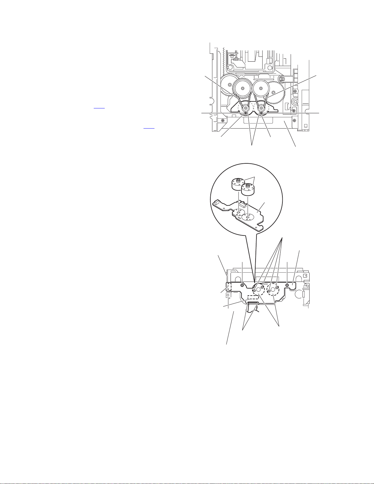
3.2.4 Removing the motor board
(See Figs.9 and 10)
(1) From the top side of the DVD changer mec ha nis m a ssem -
bly, remove the two belts from the motor pulleys. (See
Fig.9.)
Note:
Take care not to attach grease on the belt.
(2) Remove the two screws D attaching th e motors to th e load-
er assembly. (See Fig.9.)
(3) From the bottom side of the DVD changer mechanism as-
sembly, remove the two screws E. (See Fig.10.)
(4) Disconnect the connecto r CN2
tray switch board and remove the motor board. (See
Fig.10.)
(5) Disconnect the card wire from the connector CN1
forward side of the motor board. (See Fig.10.)
Note:
When connecting the card wire, let the card wire through the
slots h of the motor board. (See Fig.10.)
Reference:
You need not to remove the tray assemblies, an d in such case,
move it.
3.2.5 Removing the motor
(See Fig. 10)
• Remove the motor board.
(1) From the reverse side of the mot or board, un solder the fou r
soldered sections i on the motor board.
(2) From the forward side of the motor board, remove the mo-
tors.
on the motor bo ard from the
on the
Belt
D
Motor Motor
Motor pulleys
Fig.9
Motors
Motor board
Belt
D
Loader assembly
i
Tray switch
board
E
CN2
CN1
h
DVD changer mechanism assembly
Fig.10
Motors
Motor board
E
1-22 (No.MB616<Rev.002>)
Page 23
3.2.6 Removing the DVD traverse mechanism assembly
(See Fig.11)
• Remove the tray assemblies and DVD servo board.
(1) From the bottom side of the DVD changer mechanism as-
sembly, remove the three screws F attaching the DVD
traverse mechanism assembly.
(2) Remove the wires from the section j.
(3) Take out the DVD traverse mechanism assembly from the
DVD changer mechanism assembly.
DVD changer mechanism assembly
F
j
F
F
DVD traverse mechanism assembly
Fig.11
(No.MB616<Rev.002>)1-23
Page 24
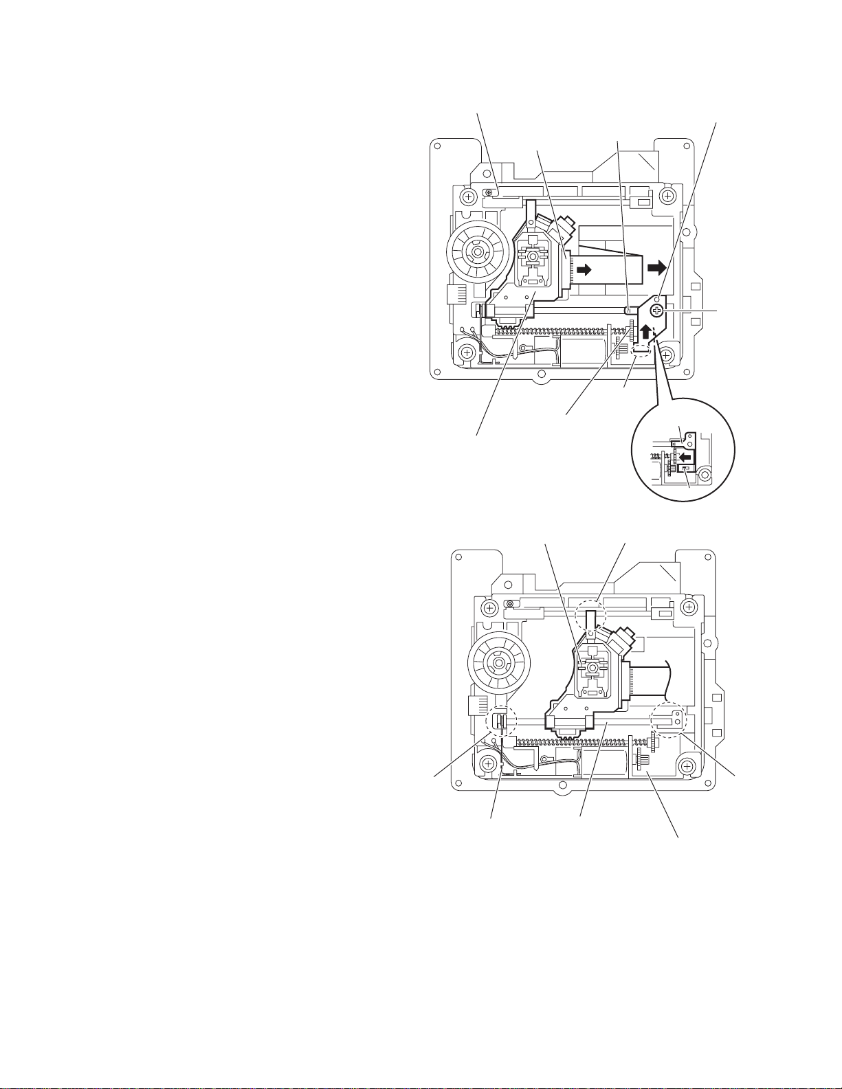
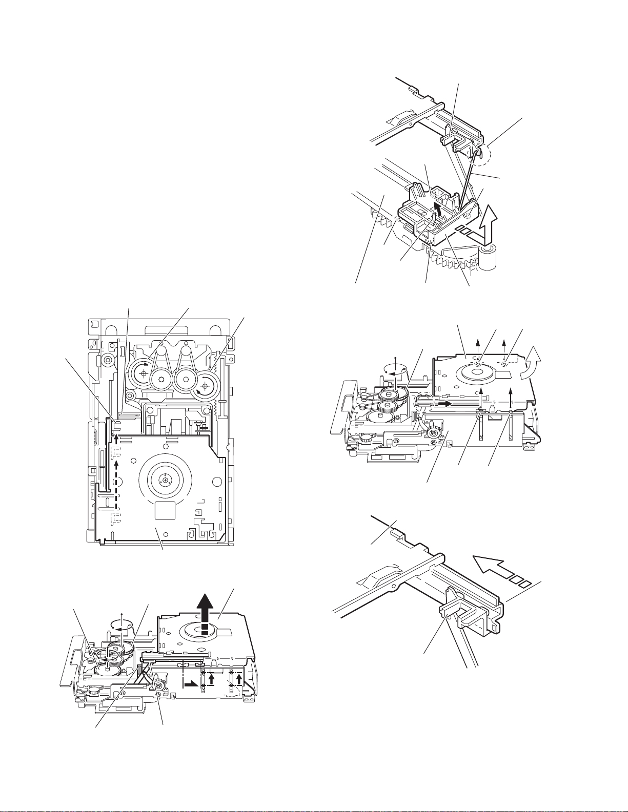
3.2.7 Removing the DVD pickup
(See Figs.12 to 14)
• Remove the tray assemblies, DVD servo board and DVD
traverse mechanism assembly.
(1) From the top side of the DVD traverse mechanism assem-
bly, release the lock of the connector on the DVD pickup
and disconnect the card wire in the direction of the arrow.
(See Fig.12.)
(2) Turn the screw shaft gear in the direction of the arrow 1 to
move the DVD pickup in the direction of the arrow 2. (See
Fig.12.)
(3) Remove the screw G attaching the feed bracket and re-
move the feed bracket from the sections k. (See Fig.12.)
(4) Release the claw m of the thrust spring in the direction of
the arrow and remove the thrust spring. (See Fig.12.)
(5) Remove the guide shaft from the sections (n, p) on the
C.TM chassis. (See Fig.13.)
(6) Remove the section q of the DVD pickup. (See Fig.13.)
(7) Remove the two screws H attaching the rack arm spring
and rack arm. (See Fig.14.)
(8) Pull the guide shaft from th e DV D pi ck up in the direct ion of
the arrow. (See Fig.14.)
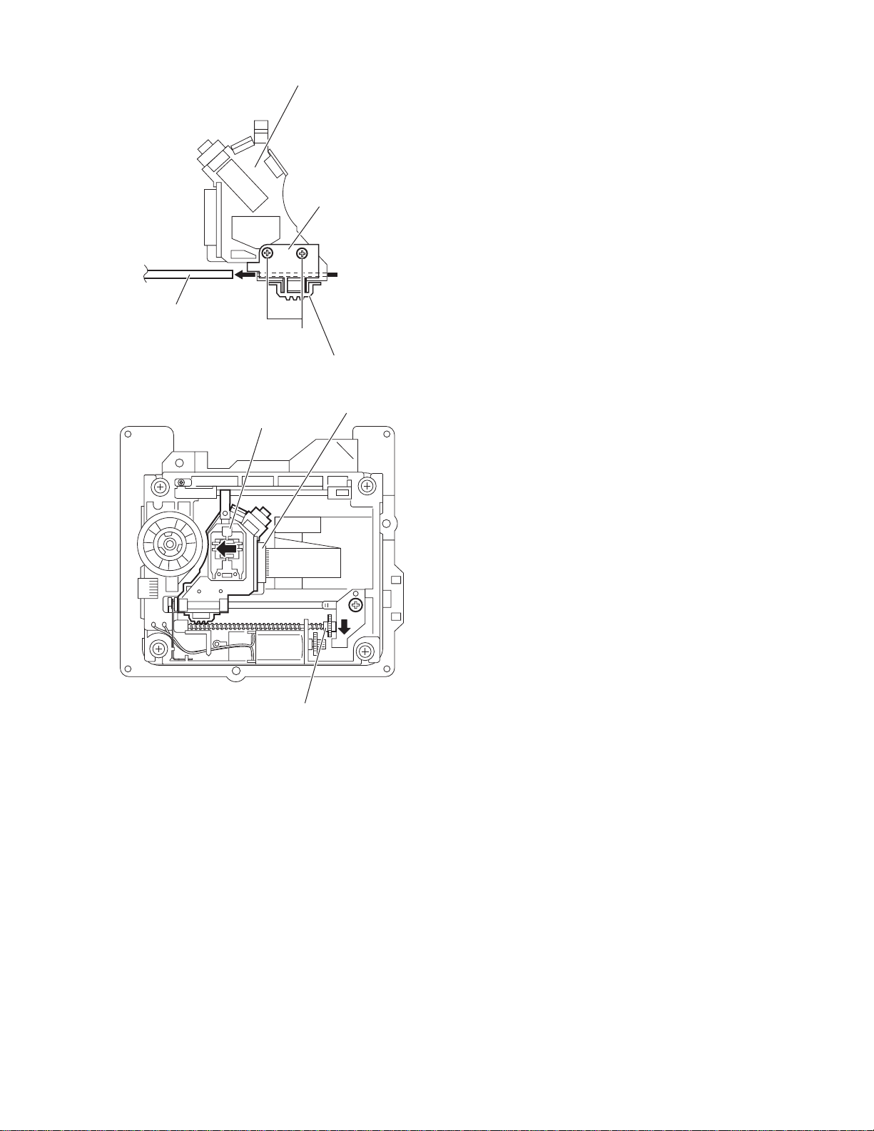
3.2.8 Attaching the DVD pickup
(See Figs.12 to 14)
(1) Attach the guide shaft to the DVD pickup and attach the
rack arm spring and rack arm with the screws H. (See
Fig.14.)
(2) Attach the section q of the DVD pickup to the C.TM cha ssis
first and attach the guide shaft to the sections (n, p). (See
Fig.13.)
Reference:
When attaching the guide shaft to the se ction p, attach i t
under the rod spring. (See Fig.13.)
(3) Attach the thrust spring and feed bracket with the s crew G.
(See Fig.12.)
(4) Turn the screw shaft gear in the direction of the arrow 1 to
move the DVD pickup in the direction of the arrow 2. (See
Fig.15.)
(5) Connect the card wire to the connect or on the DVD pi ckup.
(See Fig.15.)
DVD traverse mechanism assembly
Thrust spring
Connector
Screw shaft gear
DVD pickup
Fig.12
DVD pickup
1
k
Thrust spring
q
Feed bracket
2
G
m
1-24 (No.MB616<Rev.002>)
p
Rod spring
n
Guide shaft
C.TM chassis
Fig.13
Page 25
Guide shaft
DVD pickup
Rack arm
H
Rack arm spring
Fig.14
Connector
DVD pickup
222
Screw shaft gear
Fig.15
1
(No.MB616<Rev.002>)1-25
Page 26
3.2.9 Removing the spindle motor board
(See Figs.16 and 17)
• Remove the tray assemblies, DVD servo board and DVD
traverse mechanism assembly.
(1) From the top side of the DVD traverse mec ha nis m a ss em -
bly, remove the wires from the soldered sections r on the
spindle motor board. (See Fig.16.)
(2) From the bottom side of the DVD traverse mechanism as-
sembly, remove the three screws J attaching the spindle
motor board. (See Fig.17.)
Reference:
When attaching the spindle motor board, let the card wire
through the hole s on the C.TM chassis. ( See Fig.17. )
DVD traverse mechanism assembly
Spindle motor board
r
Fig.16
DVD traverse mechanism assembly
s
J
C.TM chassis
Fig.17
1-26 (No.MB616<Rev.002>)
Page 27
3.2.10 Removing the feed motor
(See Figs.18 and 19)
• Remove the tray assemblies and DVD traverse mechanism
assembly.
(1) From the top side of the DVD traverse mechanis m as s em-
bly, remove the screw K at taching th e fe ed brac ket an d remove the feed bracket from the sections t. (See Fig.18.)
(2) Release the claw u of the thrust spring in the direction of
the arrow and remove the thrust spring. (See Fig.18.)
(3) Remove the screw shaft from the section v and remove it
in the direction of the arrow. (See Fig.19.)
(4) Remove the middle gear. (See Fig.19.)
(5) Remove the screw L attaching the feed motor to the C.TM
chassis. (See Fig.19.)
(6) Remove the wires from the soldered sections w on the
spindle m otor board. (See Fig. 19.)
(7) Take out the feed motor from the motor base.
Reference:
After attaching the feed m otor, pas s the wires thro ugh the s ections x on the C.TM chassis as before. (See Fig.19.)
Feed bracket
Thrust spring
K
t
Thrust spring
Spindle motor board
w
x
Fig.18
Middle gear
v
Screw shaft
u
C.TM chassis
L
Fig.19
(No.MB616<Rev.002>)1-27
Page 28
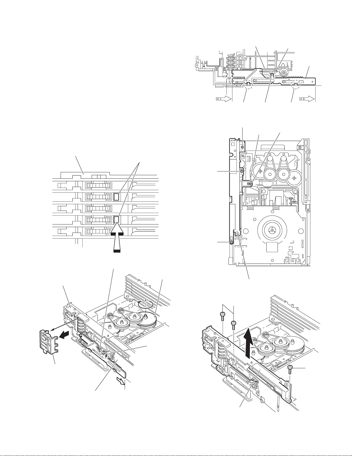
3.2.11 Removing the side (L) and tray switch board
(See Figs.20 to 22)
• Remove the tray assemblies.
(1) From the topside of the DVD changer mechanism assem-
bly, remove the two screws M attaching the side (L). (See
Fig.20.)
(2) From the left side of the DVD changer mechanism assem-
bly, disconnect the con nector CN3
from the motor board and de tac h th e s id e (L) in an u pw ard
direction. (See Fig.21.)
(3) Remove the screw N attaching the tray switch board to the
side (L). (See Fig.22.)
(4) Release the joint tab y of the side (L) in the direction of the
arrow 1 and release the joint tab z while removing the tray
switch board in the direction of th e arrow 2. (See Fig.22.)
on the tray switch board
SIde(L)
M
M
DVD changer mechanism assembly
Fig.20
M
Side(L)
M
CN3
Tray switch board
Motor board
Side(L)
Fig.21
y
1
1-28 (No.MB616<Rev.002>)
2
z
Tray switch board
N
Fig.22
Page 29
3.2.12 Removing the side (R) assembly
(See Fig.23 to 27)
• Remove the tray assemblies and DVD servo board.
(1) From the inside of the side (R) assembly, release the two
tabs aa of the gear cover and remove the gear cover outward. (See Figs.23 and 24.)
(2) From the right side of the DVD changer mechanism as-
sembly, remove the elevator spring attached to the hook
ab of the loader assembly. (See Figs.24 and 25.)
(3) From the top side of the DVD changer mechan is m as s em-
bly, turn the gear 1 clockwise to move the elevator cam
rearward. (See Fig.25.)
(4) Move the two slots ac and joint ad of the elevator cam and
remove the elevator cam outward. (See Fig.25.)
(5) Remove the three screws P and detaches the side (R) as-
sembly upward. (See Figs.26 and 27.)
Note:
When reattaching the side (R) assembly, make sure to fit the
shaft (part ae) into the slot of the select lever. (See Fig.26.)
Side(R) assembly
aa
P
Elevator spring
ac
Fig.25
P
ae
ab
Elevator cam
acad
Select lever
Side(R) assembly
Gear cover
Loader assembly
P
Fig.23
Elevator spring
Gear 1
Side(R) assembly
Fig.26
P
ab
P
Fig.24
Side(R) assembly
Fig.27
(No.MB616<Rev.002>)1-29
Page 30
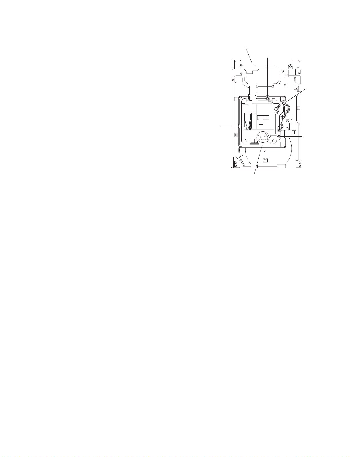
3.2.13 Removing the lifter assembly
(See Figs.28 to 32)
• Remove the tray assemblies, DVD servo board, side (L) and
side (R) assembly.
(1) From the top side of the DVD changer mec ha nis m a ssem -
bly, turn the gear 1 clockwise to move the lifter assembly
upward. (See Figs.28 and 29.)
(2) Turn the gear 2 clockwise to move the hook toward the
front until it stops. (See Figs.28 and 29.)
(3) Move the hook stopper in the direction of the arrow 2 while
pushing the tab af of the hook stopp er to unlo ck it i n the di rection of the arrow 1 and release four joints ag to detach
from the rack holder. (See Fig.30.)
(4) Release the rod (L) from part ah. (See Fig.30.)
(5) Turn the gear 1 clockwise again to move the lifter assembly
upward. (See Fig.31.)
(6) Remove the lifter assembly from the DVD chan ger mecha -
nism assembly upward at the positions ai where the four
pins on the bot h sides of the lifte r ass embly f it to the no tch -
es of the loader assembly. (See Fig.31.)
(7) Move the lifter assembly in the direction of the arrow and
release it from the hook. (See Fig.32.)
Hook stopper
Gear 2
Gear 1
ag
Rack holder
af
Hook
ag
1
ag
Hook stopper
Fig.30
Lifter assembly
ag
2
Rod(L)
ai
ah
ai
Hook
Gear 2
Lifter assembly
Fig.28
Gear 1
Lifter assembly
Gear 1
ai
Loader assembly
Fig.31
Lifter assembly
ai
Hook stopper
1-30 (No.MB616<Rev.002>)
Hook
Fig.32
Hook
Fig.29
Page 31

3.2.14 Removing the sensor board and SV resistor
(See Fig.33)
• Remove the tray assemblies, side (L), side (R) assembly and
lifter assembly.
(1) Remove the solders from the soldered sections aj on the
sensor board and remove the wires.
(2) Remove the two screws Q and take out the sensor board
with the SV resistor.
Reference:
• Remove the soldered section ap on the s ens or boa rd as required.
• When reassembling, pass the wires through the slot ak of
the sensor board as before.
Note:
When reattaching the SV. resi ste r, fit th e proj ec tio n am on the
bottom of the SV. resister into slot an of the sensor slider.
Sensor board
Q
ap
Q
ak
aj
SV resistor
am
an
SV resistor
Slider
Fig.33
(No.MB616<Rev.002>)1-31
Page 32

3.2.15 Taking out the disc in the play mode
(See Fig.34 to 37)
Reference:
Refer to "Removing the tray assemblies".
(1) From the top side of the DVD changer mec ha nis m a ssem -
bly, remove the top cover.
(2) Unlock the tray assemblies and draw out the tray assem-
blies toward the front.
(3) From the top side of the DVD changer mec ha nis m a ssem -
bly, turn the gear 1 clockwise to move the lifter assembly
upward. (See Fig.34.)
(4) Turn the gear 2 clockwise to move the sub tray remaining
inside the lifter assembly toward the front, then pull out.
(See Fig.34.)
(5) Take out the disc on the sub tray. (See Fig.35.)
(6) After clearing away the disc, insert the sub tray into the
main tray. (See Fig.36.)
Note:
When reattaching t he su b tray, move the tra y sto pper on
the bottom of the main tray in the direction of the arrow
to lock the sub tray certainly. (See Figs.36 and 37.)
(7) Push the tray assembly toward the DVD changer mecha-
nism assembly and reattach.
Tray assembly
Gear 2
Gear 1
Sub tray
Fig.34
Tray assembly
Fig.35
Disc
Sub tray
1-32 (No.MB616<Rev.002>)
Page 33

Tray stopper
r
Main tray
Sub tray
Fig.36
Tray stoppe
Fig.37
(No.MB616<Rev.002>)1-33
Page 34

SECTION 4
ADJUSTMENT
4.1 Attention in service of DVD section
(1) When pickup, Flash ROM, DVD module board were changed, initialize EEPROM by all means.
(2) When full i nitialization was executed, execute learning with a DVD test disk by all means.
Test disc : VT-501, VT-502
Learning m ethod : It is adjusted automatically by normal playback of a DV D test disc.
4.2 TO ENTER DVD TEST MODE.
a) AC Power OFF.
b) Press and hold STOP + DVD PLAY keys on the front panel. Then AC power ON while holding these keys.
c) DVD Mecha will start in TEST MODE. The following will be display on the set.
xx = Destination information as follows; JC/1U/D/E/2U/3U/UB/UT/4U/UY/EE/UF
y = region number
v = study state information from MECHA-CON
w = initialization state from MECHA-CON
4.3 TO EXIT DVD TEST MODE
During TEST MODE, press POWER key.
4.4 DVD MODULE EEPROM INITIALIZATION
'v' Status
DVD Learned
'CD Learned
'w' Status
Initialize Status
0123
YNYN
YNYN
03
Normal Full
BLANK(0xFF)
Not Initialize
y
xxwvT
No
1)
2)
STEP NORMAL INITIALIZE FULL INITIALIZE
During DVD TEST MODE Press key on front panel.
System display -> w status w = 0 (Normal initialize)
4.5 DEVICE KEY CHECKSUM DISPLAY
a) During TEST MODE, press MENU key on remocon to enter DEVICE KEY CHECKSUM display
for DVD-AUDIO (CPPM).
b) System will display as follows.
c) Press MENU again to enter DEVICE KEY CHECKSUM display for DVD-VR MODE (CPRM).
d) System will display as follows.
4.6 DVD CHECK MODES
a) Press MENU key again to enter CHECK MODE.
i) During CHECK mode, press '1' key on REMOTE CONTROL to START PLAYBACK.
ii) During CHECK mode, press '2' key on REMOTE CONTROL to perform SEARCH TNO+1
Status: AA 00 cc cc jj jj
iii) During CHECK mode, press '3' key on REMOTE CONTROL to perform SEARCH TNO-1
iv) During CHECK mode, press '4' key on REMOTE CONTROL to light up CD_LD and
display CD laser current.
v) During CHECK mode, press '5' key on REMOTE CONTROL to light up DVD_LD and
display DVD laser current.
vi) During CHECK mode, press '6' key on REMOTE CONTROL to enter DVD x 2 JITTER
MEASUREMENT MODE.
vii) During CHECK mode, press '7' key on REMOTE CONTROL to view DVD module EEPROM
content in -1 address step.
Press STOP key on front panel and hold for 4 seconds.
w = 3 (Full initialize)
(KEY INDEX)
(DEVICE KEY INFO)
(DEVICE KEY CHECKSUM)
(KEY INDEX)
(DEVICE KEY INFO)
(DEVICE KEY CHECKSUM)
(TEST MODE, MODE STATUS, CHECK MODE)
(2 seconds)
(2 seconds)
(Static)
(2 seconds)
(Static)
(2 seconds)
(Static)
(2 seconds)
(Static)
xMPxxC Px
xRM xxC
Px
CHECK
LA
BAY KCP
BOB E
WL
cj
jcc jjc
CK
CHE
DL
LD RSC
jcc jjc
cj
D
DL RSD
VL
cj
jcc jjc
I1
TXJ
jcc jjc
cj
EW
PB DE
jcc jjc
cj
1-34 (No.MB616<Rev.002>)
Page 35

viii) During CHECK mode, press '8' key on REMOTE CONTROL to view DVD module
EEPROM content in +1 address step.
(2 seconds)
(Static)
ix) During CHECK mode, press '9' key on REMOTE CONTROL to perform TEMPERATURE
SENSOR VALUE.
(2 seconds)
(Static)
x) During CHECK mode, press '10' key on REMOTE CONTROL to perform SEARCH
DVD_DL PARALLEL DISC DESIGNATED POSITION and JITTER MEASUREMENT
(2 seconds)
(Static)
xi) During CHECK mode, press '0' key on REMOTE CONTROL to perform monitor output.
(2 seconds)
(Static)
PE E
FDW
cj
jcc jjc
EPM
T
jcc jjc
cj
DD-D VL
jcc jjc
cj
NIM OT
OR
jcc jjc
cj
xii) During CHECK mode, press '+10' key to INITIALIZE DVD module EEPROM.
xiii) During CHECK mode, press PLAY key on REMOTE CONTROL to start PLAYING
and obtain LASER CURRENT and JITTER value.
(2 seconds)
(Static)
xiv) During CHECK mode, press STOP key on REMOTE CONTROL to stop JITTER
measurement.
(Static)
b) During CHECK mode, at any time press MENU key to exit CHECK mode and return to
starting screen of DVD TEST MODE.
SECTION 5
TROUBLESHOOTING
ITI
N
RJTL SI
jcc jjc cj
jcc jjc cj
This service manual does not describe TROUBLESHOOTING.
(No.MB616<Rev.002>)1-35
Page 36

Victor company of Japan, Limited
Audio/Video Systems category 10-1,1chome,Ohwatari-machi,Maebashi-city,371-8543,Japan
(No.MB616<Rev.002>)
Printed in Japan
VPT
Page 37

SCHEMATIC DIAGRAMS
COMPACT COMPONENT SYSTEM
DX-U10A,DX-U10US,DX-U10UX
DX-U10UG,DX-U10UN,DX-U8US
DX-U8UX,DX-U8UG,DX-U8UN
DX-U6US,DX-U6UX,DX-U6UG
DX-U6UN
CD-ROM No.SML200706
SP-DXU10W SP-DXU10W
SP-DXU10S SP-DXU10S
Contents
Block diagrams
Standard schematic diagrams
Printed circuit boards
SP-DXU10F SP-DXU10F
SP-DXU10W
Lead free solder used in the board (material : Sn-Ag-Cu, melting point : 219 Centigrade)
Lead free solder used in the board (material : Sn-Cu, melting point : 230 Centigrade)
CA-DXU10
SUPER VIDEO
CA-DXU6
SP-DXU6F SP-DXU6F
SP-DXU10C
SP-DXU10W
SP-DXU8S
SUPER VIDEO
CA-DXU8
SP-DXU10F
SP-DXU8S
SP-DXU10F
SP-DXU10C
2-1
2-2
2-16 to 19
COPYRIGHT 2007 Victor Company of Japan, Limited.
No.MB616SCH
2007/6
Page 38

In regard with component parts appearing on the silk-screen printed side (parts side) of the PWB diagrams, the
parts that are printed over with black such as the resistor ( ), diode ( ) and ICP ( ) or identified by the " "
mark nearby are critical for safety.
Page 39

Block diagram
SW6
TRAY OPEN SW
SW1 to SW5
TRAY CLOSE SW
DVD
traverse
mechanism
J580
USB
D+/-
USB,LED
Key matrix
MIC
VOLUME
ECHO
VOLUME
MIC1
MIC2
HEAD
PHONE
PB
HEAD
REC/PB
ERASE
HEAD
W580
J902
MOTPSW
CLSWT1 to 5
DVD servo and system control section
A, B, C, D, E, F, RF+, LPC1, LPC2
LD(CD)
CN101
LD(DVD)
F+/T+/-
FM+/WOUT
VOUT
UOUT
COM
CN201
TRVSW
DP
CN811
DM
USB5V
Q101 to Q104
LASER DRIVER
IC201
DRIVER
IC505
SDRAM
IC801,Q801
5V REG.
Front panel section
S5500 to S5517
USB5V
FL500
JS901
MICVOL+/-
JS902
ECHO+/-
J901
J910
HPL/R, HP-SW
DISC/TAPE KEY
D5500 to D5503,Q5500
ILLUMINATION LED
P1 to 24
G1 to 14
FL
FL1
FL2
Microphone
IC901
MIC AMP.
FW910
Headphone
CN220
Tape record and playback section
CN200
Q300,Q301,L300
BIAS OSC
PB 2WAY
SWITCH
R/P 2WAY
SWITCH
PACK, ENDSW-A
R-REC, F-REC
PACK, ENDSW-B
TRAY/POSITION
CN2
CN3
SPDRV
TRSDRV
FODRV
TRDRV
FG
SPMUTE
MOTOR
LPCO1
LPCO2
CDLDCUR
DVDLDCUR
X302,IC303
48MHz
X301
27MHz
IC510
EEPROM
MA0 to 11, MDQ0 to 15
BA0, BA1, DQM0, DQM1
MCK, NCSM, NRAS
NCAS, NWE
NEN
USB6V
F-KEY2, F-KEY3
LED-ILLU
IC500,Q5011 to Q5014
FL DRIVER
MICIN
MIC_CAL
MICSW
FW910
Q9002
HP MUTE
Q200 to Q204
REC MUTE
HSW+RECB(ACMSFTY)
M
SOLENOID
M
SOLENOID
M
TRAY/POSITION MOTOR DRIVER
DISCSET
DISCSTP
SCS, UCS
UCLK
S2UDT
U2SDT
CPURST
NEXCE, NEXOE, NEXWE
EXADT0 to 15
EXDT0 to 15
EXADR16 to 20
IC301
TX, DAC1OUT to DAC5OUT
DV5
SDA
SCK
AOUT1 to 2, DAC1CS, DAC2CS
Used for except DX-U6
DCLK, DDATA, DACPDN
BCK, LRCK, DACCK
S5011 to S5016
FW501
FW501
TAPE FUNCTION KEY
F-KEY3, LED-ILLU
S5000 to S5010
FUNCTION KEY
FL_CLK
FL_DA, FL_LATCH
FL display,LED,Key matrix,Remocon
HPL/R
HPMUTE
HPSW
AIN(L)/(R)
BIN(L)/(R)
RECOUT(L)/(R)
MTR-A
SOL-A
MTR-B
SOL-B
MTR-A
CN110
SOL-A
SOLENOID DRIVE A
MTR-B MOTOR_B
CN120
SOL-B
SOLENOID DRIVE B
IC1, IC2
MTOP, MTCL
POSMUP
POSMDN
CN1
CN451
CLSWT1 to 5
MOTPSW, MTOP, MTCL
POSMUP, POSMDN
FLASH
F-KEY1
D5004 to D5006
BASS/KARAOKE
/STANDBY LED
IC200
AUDIO
SIGNAL
PROCESSOR
Q11 0,Q 111
MOTOR DRIVE A
Q120,Q121
Q140,Q141
MOTOR DRIVE B
Q150,Q151
DVD tray control section
R1
POSITION
SENSOR
W2
CN453
LSENSOR STEDSW
IC451
MECHA CONT.
IC453
3.0V DET
IC509
ROM
F-KEY2
PBL/R
RECL/R
PBMUTE
REC-BM
A/B
IC705
A5V REG.
IC702,IC703
REAR/C/SW DAC
AOUT0, DAC0CS
REMOCON
LED_STBY
LED_BASS, LED_KROK
MOTOR_A
ACMKEY_A, ENDSW_A
SOL_A
HEADSW
ACMKEY_B, ENDSW_B
SOL_B
SUB TRAY
END SW
DVDPWR
A6VA5V
IC510
SW8
W1
CN452
EPDI, EPDO
EPCS, EPSK
X451
8MHz
P3.3V
S3.3V
D1.2V
IC305
3.3V REG.
IC302
D1.2V REG.
RAOUTL/R, CAOUT, SWAOUT
IC704
ADC
IC701
FRONT DAC
REM
CN500
FL1(S4)
FL2(S4)
FL-35V
FW500
CN901
CN100
DISPRST
DISPBUSY
DISPCS
DISPCK
DISPD2S
DISPS2D
IC452
EEPROM
D4V
ADINL/RADIN, ADCPDN
FAOUTL/R
LRMUTE
TO
TUNER
MODULE
USB6V
D2V
CN701
System control & Audio section
Used for except DX-U6
RAOUTL/R
CN810
CN703CN801
CAOUT
SWAOUT
CN800
CN702
LRMUTE
ADINL/R
TU_DI, TU_DO
TU_CE, TU_CLK
CN750
TUL/R
REM
F-KEY1 to 3
LED_ILLU
LED_STBY
LED_BASS
LED_KROK
FL_CLK
CN720
FL_DA
FL_LATCH
HPL/R
MICIN
MICVOL+/ECHO+/MIC_CAL
MICSW
HPMUTE
HPSW
RECL/R
PBL/R
PBMUTE, REC-B/M, A/B
CN730CN740
ACMSFTY
MOTOR_A, ACMKEY_A
ENSW_A, SOL_A
HEADSW
MOTOR_B, ACMKEY_B
ENSW_B, SOL_B
Used for
DX-U6
FAOUTL/R
INL1, INR1
KARAOKE
IC870
Q8070,Q8071
SURR E.VOL/MUTE
IC880
C/SW E.VOL
IC800,IC801
DVD FRONT
/SW MIX
SAOUT
IC820
MAIN
E.VOLUME
Used for
DX-U6
OUT
INL3
INR3
MIC_DA
MIC_CLK
MIC_FOUT
IC850
SURR_DA
VOL_CLK
SL, SR
LOUT
RVIN
ROUT
C/SW_DA
VOL_CLK
VOLOUTL/R
MAIN_DA
VOL_CLK
INL2
INR2
RECL/R
NOTES: (CN303) Used for DX-U6
NOTES: (IC307) Used for DX-U8
DISPRST, DISPBUSY, DISPCS
DISPCK, DISPD2S, DISPS2D,
Used for except DX-U6
SMUTE
IC881
SW LPF
IC830,IC831
Q8030 to Q8032
Q8130 to Q8132
AHB CCT/SW
AHBL, AHBH
AIBASS_SW
ADINL/R
AUX/TAPE
LEVELFB
IC770
MICON
RESET
EEP_DA
EEP_CLK
V_I/P, V_MUTE
CTR
Q8081
C SMUTE
FDVD, AMP-ON
FANSFTY, FANCTRL
SW_LEV1
SW_LEV2
Q8403
Q8404
SW LEVEL
Used for DX-U6
Q8180
SW
SMUTE
Q8040
MAIN
SMUTE
SMUTE
PRT
AMP-ON
Used for DX-U6
Used for except DX-U6
IC810,Q8211,Q8212
PBL/R
AUX/TAPE SWITCH
D7151,D7152
F/SW_RLY
D7153
D7157
Q7000
SW1
SW2
D7154
D7155,D7156
C/R_RLY
Q7010
Used for except DX-U6
Q7080
RESET
X7700
8MHz
IC771
EEPROM
SW
FL
FR
FL
FR
SL
SR
C
Video & Digital output section
USB6V
CN930 CN920CN921
DISPRST, DISPBUSY, DISPCS
DISPCK, DISPD2S, DISPS2D
CN760
Amp & Regurator section
CN302(CN303)
C, Y-1, Y-2, Cb, Cr
V_I/P, V_MUTE
D5V,S5V,USB6V,M9V
CN830
SL, SR
CTR
AMP-ON
USB6V
A9V,M12V
IC301(IC307)
SURROUND
/CENTER AMP.
Used for except DX-U6
Amp section
SW
AMP-ON
CN403
CN820
FL, FR
PRT
NOTES: (IC403) Used for DX-U10
AUXL/R
IC402
SUBWOOFER AMP.
IC401(IC403)
FRONT AMP.
Q4901 to Q4904
Q4601,Q4701,Q4951
PROTECTOR
J800
AUX IN
J700
SPEAKER
SPK
SPK
SPK
L
R
FRONT
SURROUND(DX-U6)
SW1
SUBWOOFER1
SW2
SUBWOOFER2
(DX-U8,DX-U10)
SL
SR
SURROUND
(DX-U8,DX-U10)
C
CENTER
RY712
RELAY
RY767
RELAY
RY734
RY756
RELAY
(DX-U8,DX-U10)
CN203
CN850
FL, FR, SW1, SW2
SL, SR, C
Bridge section
Q2300,Q2301
D2315,D2317
-35V REG./FL BIAS
FL-35V
CN207
S1,S4
S4
S1,S2,S3,S4,S3CT
CN201
T1001
TRANS.
TX
Y
C
CV
IC920
VIDEO
DRIVER
CN931
FW301
Q3401,Q3501,Q3601
PROTECTOR
SL, SR, C
Used for DX-U10
Q4101,Q4201
PROTECTOR
SW1, SW2
FL, FR
DC
IMP
VH+/VL+/-
CN404
CN205
VL+/VH+/-
VL+/-
D2001
+/-VL BRIDGE
S2
D2200 to D2203
BRIDGE for REG.
CN101 CN102
Used for except
Area suffix A
VOLTAGE SWTCH
IC930 J921
OPTICAL
DIGITAL OUT
S/COMPOSITE
Y
VIDEO OUT
Cb
J920
COMPONENT
Cr
VIDEO OUT
FANSFTY
FANCTRL
CN301
(CN307)
NOTES:
(CN307)
Used for
DX-U6
CN204 FW201
DC
IMP
+/-VH BRIDGE
S3DC
S3
S1000
M
FAN MOTOR
CN304
Q3901,Q3902
FAN DRIVE
DC
IMP
USB6V
D5V
S5V
IC305
DVD5V
FDVD
M9V
IC306
MOTOR9V REG.
S3DC
A9V
IC304
A9V REG.
IC302
M12V
ACM12V
REG.
S3DC
S3L
VL+/VH+/-
CN305
CN306
Used
for
except
DX-U6
S3DC
S3L
D2101
VL+/VH+/-
VH+/-
S1
D2204
S3L BRIDGE
Primary
section
CN100
AC
INPUT
USB6V
IC303
REG.
S3L
REG.
S3L
S3DC
S3DC
S3L
S3CT
2-1
Page 40

Standard schematic diagrams
Primary section
S3DC
QGB2510J1-16
CN204
QGB2510J1-10
CN205
QGB2510K2-16
CN203
R2002
100K
C2011
220/35
C2010
220/35
PGND
C2006
R2003
4700/35
100K
FL
C2008
4700/35
FR
2A02-M
D2002
SW1
PP201
QNZ0104-001
2A02-M
D2003
C
QUB070-22BXDM-E
!
C2009
C2005
NI
RL
W201
0.1/250
C2007
RR
GBU803
NI
D2001
SW2
R2200
100K
C2214
C2213
4700/35
6800/16
D2204
2A02-M
!
F2006
0.1/50
Q2300
KTA1046/Y/
0.01
!
!
1N5402M-20
!
1N5402M-201N5402M-20
R2301
D2200
D2201D2203
QGA7901C1-02
CN100
QGA7901C1-03
CN102
!
!
T1001
QQT0536-001
B1951
C1001
!
F1002
*
B1202
C1002
CN101
QGA7901C1-04
QGA3901C1-10
*
CN201
!
F1001
!
S1000
QSW0812-001
!
F2005
!
F2004
!
F2003
D2317
1N4003S-T5
D2315
1N4003S-T5
43K
43K
R2305
R2306
R2300
FLBIAS
!
47
!
47
B1201
R2307
R2308
B1601
47
47
!
D2202
1N5402M-20
C2212
!
F2001
!
F2002
!
C2304
C2115
0.1/250
D2101
GBU803
C2116
NI
!
NI
C2117
FW201
QUM15A-18DGZ4-E
R2000
100K
C2000
4700/63
2A02-M
D2003
2A02-M
D2002
R2001
100K
C2004
4700/63
D2312
Q2301
KTC3203/OY/-T
C2305
10/50
2-2
MTZJ7.5B-T2
R2302
100K
C2303
22/50
D2314
MTZJ36A-T2
D2313
22/50
C2302
C2316
220/100
NI
CN207
QGD2504C1-03Z
FL-35V
Parts are safety assurance parts.
When replacing those parts make
sure to use the specified one.
Page 41

DC regulator/Audio output section (for DX-U10)
FW301
QUM156-27DGZ4-E
!
IC301
STK416-130-E
IC306
!
KIA278R09PI
INP
D3812
NI
D3813
D3814
NI
D3815
NI
B3104
NI
B3103
C3812
C3811
22/50
100/16
B3101
B3102
D3811
MTZJ11B-T2
PQ050RDC2SZF
!
IC305
100/16
C3702
C3701
47/25
D3822
NI
R3701
10K
D3701
D3823
MTZJ6.2B-T2
D3824
D3825
NI
IC304
KIA7809API
!
IN
B3108
NI
B3107
C3822
100/16
22/50
C3821
D3821
NI
B3106B3105
MTZJ11B-T2
D3207
NI
CN304
QGA2501F1-03
!
C3831
47/25
C3832
Q3901
KTA1271/0Y/-T
100/16
KIA78D06PI-U/P
D3832
MTZJ6.8B-T2
R3907
IC303
C3833
1K
Q3902
KTC3199/GL/-T
2200/6.3
B3110 B3111
NI
D3845
NI
NI
D3844
D3843
B3109
IC302
!
KIA7812API
NI
D3842
INPUT
B3112
D3841
C3842
100/16
22/50
C3841
QGB2510K2-10
QGD2504C1-05Z
CN301
MTZJ13B-T2
CN305
R3306
100
NI
B3205
B3204
B3203
!
R3305
!
100
D3306
1N5402M-20
D3305
1N5402M-20
C3301
C3302
0.1/100
CN306
QDG2504C1-05Z
0.1/100
NI
B3603
D3301
MTZJ15B-T2
D3303
MTZJ36B-T2
R3411
KTC3199/GL/-T
+REF
-VL
+VL
6.8K
R3301
6.8K
R3302
2K
2K
R3406
1K
C3401
NI
Q3401
D3401
5.6K
R3408
-REF
MTZJ15B-T2
R3303
R3407
6.8K
-PRE( -VH)
R3304
L3401
47K
+VH
-VH
D3302
6.8K
D3304
!
0.39
R3403
!
R3404
100K
C3405
R3410
MTZJ36B-T2
1010
KTC3199/GL/-T
0.1
C3404
0.1
!
R3401
+SR/LCH
0.22
R3511
+SR/RCH
-SR/LCH
-SR/RCH
SGND
+PRE( +VH)
B3100
NI
R3308
C3402
3.3P
R3402
56K
R3501
0.22
!
C3502
3.3P
R3502
2K
2K
R3505R3405
R3506
Q3501
D3501
R3508
56K
1K
C3501
NI
!
0.39
R3503
L3501
!
47K
R3507
R3504
5.6K
100K
R3510
C3505
STBYY
+SR-LIN
-SR-LIN
C3221
220P
47/25
C3403
10
!
330
R3409
10
0.1
C3504
0.1
+C-IN
+SR-RIN
-SR-RIN
C3211
220P
C3503
!
330
R3509
+C/O
-C/O
-C-IN
R3307
!
0.22
R3601
R3602
56K
C3602C3201
220P
3.3P
R3606
C3601
NI
R3605
1K
0.39
L3601
10
R3603
!
Q3601
47/25
C3603
47/25
!
R3609
KTC3199/GL/-T
!
270
47K
R3607
10
R3604
100K
0.1
C3604
0.1
R3610
C3605
2K
2K
2K
R3611
56k
R3204
680P
C3203
C3202
R3201
1k
10/63
C3212
R3202
1k
D3601
R3608
5.6K
1/50
C3104
10/63
56k
R3205
56k
R3206
C3222 R3203
10/63
680P
C3213
680P
C3223
1k
CN302
QGF1205C2-15
SUR-R
AGND
SUR-L
CENTER
STBY
FANSTAT
FANCTRL
FDVD
AGND
A9V
USB6V
M12V
C4901
R4902
Q4902
KTA1268/GL/-T
IC403
!
STK415-130-E
!
R4505
!
R4506
100
KTC3199/GL/-T
D4901
FW401
R4905
Q4904
KTA1268/GL/-T
R4906
C4903
10/50
10K
100K
10K
10/50
R4901
Q4901
KTC3200/GL/-T
R4903
10K
100K
Q4903
100K
47/25
R4904
C4902
D4506
100
1N5402M-20
D4505
1N5402M-20
D4501
MTZJ15B-T2
C4501
C4502
0.1/100
0.1/100
D4503
R4501
MTZJ36B-T2
R4606
2K
KTC3199/GL/-T
6.8K
R4611
R4608
2K
C4601
Q4601
5.6K
D4502
MTZJ15B-T2
R4601
6.8K
6.8K
6.8K
R4502
R4503
R4504
R4605
NI
L4601
D4601
47K
R4607
R4610
0.22
D4504
!
R4603
0.39
!
R4604
C4604C4605
100K
MTZJ36B-T2
1010
KTC3199/GL/-T
0.1
0.1
R4701
!
!
2K
2K
R4711
R4706
C4701
Q4701
D4701
R4708
5.6K
0.22
R4705
1K1K
NI
R4702
L4701
47K
R4707
CN404
QGB2510K2-16
NI
R4508
!
NI
C4602
3.3P
C4811
R4602
56K
C4702
3.3P
56K
!
10
R4703
0.39
!
10
R4704
C4704
0.1
C4705
100K
R4710
C4801
100P
100P
C4703
C4603
100/63
100/63
!
!
220
220
R4709
R4609
2K
R4507
0.1
R4951
R4952
NI
C4806
C4952
NI
NI
NI
C4951
C4953
!
R4959
R4955
NI
R4953
L4951
NI
NI
Q4951
NI
NI
R4954
NI
NI
C4954
NI
R4957
NI
C4955
NI
R4950
NI
R4960
R4956
NI
NI
C4404
1/50
D4951
NI
R4958
CN403
QGF1205F1-07
NI
R4804
C4804
NI
C4802
10/63
56k
R4802
56k
R4812
C4812 R4811
10/63
C4805
NI
R4803
NI
R4801
1k
C4803
100P
C4813
100P
1k
FW401
!
R4006
100
220/35
C4004
!
R4005
100
1N5402M-20
D4005
1N5402M-20
C4002
C4001
0.1/100
0.1/100
220/35
C4003
D4006
D4003
MTZJ15B-T2
MTZJ36B-T2
R4106
KTC3199/GL/-T
!
D4001
R4001
STK415-130-E
6.8K
2K
Q4101
D4101
R4108
IC402
NI
R4008
D4002
MTZJ15B-T2
6.8K
6.8K
6.8K
R4002
R4003
R4004
2K
R4105
R4111
C4101
NI
L4101
47K
5.6K
R4107
R4110
0.22
D4004
R4101
!
MTZJ36B-T2
2K
R4211
R4206
!
0.39
1010
R4103
KTC3199/GL/-T
!
R4104
D4201
0.1
C4104C4105
100K
0.1
R4208
Q4201
C4102
3.3P
C4311
R4102
56K
0.22
R4201
!
C4202
3.3P
R4202
2K
R4205
56K
1K1K
C4201
!
NI
5.6K
10
0.39
L4201
R4203R4204
!
10
47K
R4207
0.1
C4204C4205
100K
0.1
R4210
C4405
1/50
C4301
100P
100P
100/63
C4203
C4103
100/63
!
!
180
R4109
R4209
2K
R4007
C4302
180
10/63
56k
R4302
C4313
470P
56k
R4312
C4312
10/63
1k
R4311
Parts are safety assurance parts.
When replacing those parts make
sure to use the specified one.
2-3
Page 42

DC regulator/Audio output section (for DX-U8)
FW301
QUM156-27DGZ4-E
IC307
STK433-240-E
!
IC306
!
KIA278R09PI
INP
D3812
NI
D3813
D3814
D3815
B3104
B3103
NI
NI
NI
C3812
C3811
22/50
100/16
B3101
B3102
D3811
MTZJ11B-T2
IC305
PQ050RDC2SZF
!
C3701
+VL
-PRE( -VL)
NININININI
R3303
R3302
R3304
1K
NI
L3401
47K
R3407
-VL
D3302
NI
D3304
!
0.39
R3403
!
R3404
100K
C3405
R3410
CN304
QGA2501F1-03
!
C3831
47/25
C3832
Q3901
KTA1271/0Y/-T
100/16
IC303
KIA78D06PI-U/P
D3832
MTZJ6.8B-T2
R3907
C3833
1K
Q3902
KTC3199/GL/-T
2200/6.3
D3845
NI
D3844
B3110 B3111
B3109
NININI
D3843
IC304
KIA7809API
!
IN
100/16
C3702
47/25
D3822
NI
R3701
10K
D3701
MTZJ6.2B-T2
B3108
D3823
NI
B3107
C3822
100/16
C3821
22/50
D3821
D3702
2A02-M
MTZJ11B-T2
D3824
NI
B3106B3105
D3825
NI
IC302
!
KIA7812API
NI
D3842
INPUT
B3112
D3841
C3842
100/16
22/50
C3841
QGB2510K2-10
QGD2504C1-05Z
CN301
MTZJ13B-T2
CN305
R3306
100
B3205
NI
NI
B3204
B3203
!
R3305
!
B3603
C3002
0.1/100
100
C3301
CN306
QDG2504C1-05Z
0.1/100
D3306
NI
D3305
NI
D3301
NI
D3303
R3301
2K
2K
R3411
R3406
C3401
KTC3199/GL/-T
Q3401
D3401
5.6K
R3408
1010
C3404
0.1
+SR/LCH
0.22
R3401
!
R3511
KTC3199/GL/-T
0.1
2K
-SR/LCH
R3506
D3501
R3508
Q3501
NI
R3501
!
2K
R3505R3405
C3501
+SR/RCH
1K
5.6K
-SR/RCH
SGND
+PRE( +VL)
NI
B3100
R3308
C3402
3.3P
R3402
56K
0.22
C3502
3.3P
R3502
56K
!
0.39
R3503
L3501
!
47K
R3507
R3504
100K
R3510
C3505
STBYY
+C-IN
+SR-LIN
-SR-LIN
C3221
220P
10/50
C3403
10
!
!
330
R3409
10
0.1
C3504
0.1
-C-IN
+SR-RIN
-SR-RIN
C3211
220P
C3503
10/50
330
R3509
+C/O
-C/O
R3307
!
0.22
R3601
R3602
56K
C3602C3201
220P
3.3P
R3606
C3601
NI
R3605
1K
0.39
L3601
10
R3603
!
C3603
!
R3609
Q3601
22/50
KTC3199/GL/-T
!
270
47K
R3607
10
R3604
100K
0.1
C3604
0.1
R3610
C3605
2K
2K
2K
R3611
56k
R3204
680P
C3203
C3202
R3201
1k
10/63
C3212
R3202
1k
D3601
R3608
5.6K
1/50
C3104
10/63
56k
R3205
56k
R3206
C3222 R3203
10/63
680P
C3213
680P
C3223
1k
CN302
QGF1205C2-15
SUR-R
AGND
SUR-L
CENTER
STBY
FDVD
AGND
A9V
USB6V
M12V
FANSTAT
FANCTRL
C4901
R4902
Q4902
KTA1268/GL/-T
IC401
!
STK416-130-E
!
R4505
!
R4506
100
KTC3199/GL/-T
D4901
Q4904
KTA1268/GL/-T
R4906
C4903
10/50
R4905
10K
100K
FW401
10K
10/50
R4901
Q4901
KTC3200/GL/-T
R4903
10K
100K
Q4903
100K
R4904
C4902
47/25
D4506
100
1N5402M-20
D4505
1N5402M-20
D4501
MTZJ15B-T2
C4502
0.1/100
C4501
0.1/100
6.8K
D4503
R4501
MTZJ36B-T2
R4606
R4611
2K
R4608
2K
R4605
C4601
D4601
5.6K
R4502
NI
Q4601
MTZJ15B-T2
6.8K
R4503
6.8K
R4607
KTC3199/GL/-T
D4502
R4601
6.8K
R4504
L4601
47K
R4610
0.22
D4504
!
R4603
0.39
!
R4604
C4604C4605
100K
MTZJ36B-T2
1010
0.1
0.1
R4701
!
!
2K
2K
R4711
R4706
C4701
Q4701
D4701
R4708
5.6K
0.22
R4705
1K1K
NI
R4707
KTC3199/GL/-T
QGB2510K2-16
NI
R4508
!
0.22
100/63
220
R4951
R4952
56K
C4806
C4952
3.3P
100P
2K
NI
1K
Q4951
KTC3199/GL/-T
2K
R4960
R4956
C4404
1/50
D4951
5.6K
R4958
CN403
QGF1205F1-07
56K
R4804
C4804
10/63
C4802
10/63
56k
R4802
56k
R4812
C4812 R4811
10/63
C4805
470P
R4803
1K
R4801
1k
C4803
100P
C4813
100P
1k
FW401
NINI
C4951
100/63
R4955
0.39
R4953
L4951
10
!
220
!
R4954
10
0.1
C4954
47K
R4957
0.1
C4955
R4950
100K
C4953
!
R4959
C4602
3.3P
C4811
R4602
56K
C4702
3.3P
R4702
56K
!
10
R4703
0.39
L4701
!
R4704
47K
C4704
0.1
C4705
100K
R4710
CN404
C4801
100P
100P
C4703
C4603
100/63
!
!
220
R4709
R4609
10
2K
R4507
0.1
R4006
NI
NININI
C4004
R4005
D4006
NI
D4005
NI
NI
C4002
C4001
C4003
IC402
NI
R4008
NI
NI
D4003
D4002
D4001
NI
NI
NI
NININININI
R4001
R4002
R4003
R4004
NI
NI
R4111
R4106
R4105
C4101
NI
Q4101
L4101
NI
D4101
NININI
R4107
R4108
R4110
NI
D4004
R4101
R4201
NI
NI
R4205
R4211
R4206
NINI
C4201
NI
NI
NI
Q4201
NI
R4103
R4104
C4104C4105
NI
NI
D4201
NI
NI
R4208
NI
C4102
NI
C4311
R4102
NI
NI
C4202
NI
R4202
NI
NI
L4201
R4203R4204
NI
NI
R4207
NINI
C4204C4205
NI
R4210
C4405
C4301
NI
NI
NI
NI
C4203
C4103
NI
R4109
R4209
NI
R4007
NI
C4302
NI
NI
NI
R4302
C4313
NI
NI
R4312
C4312
NI
NI
R4311
Parts are safety assurance parts.
When replacing those parts make
sure to use the specified one.
2-4
Page 43

DC regulator/Audio output section (for DX-U6)
FW301
QUM156-27DGZ4-E
IC301
NI
IC306
!
KIA278R09PI
INP
D3812
NI
D3813
D3814
D3815
B3104
B3103
NI
NI
NI
C3812
22/50
C3811
100/16
B3101
B3102
D3811
MTZJ11B-T2
IC305
PQ050RDC2SZF
!
C3701
+VH
+SR/RCH
-SR/LCH
R3401
+SR/LCH
R3511
-SR/RCH
SGND
+PRE( +VH)
B3100
NI
R3308
C3402
NI
R3402
NI
NI
R3506
Q3501
D3501
R3508
NI
NI
R3501
C3502
NI
R3502
NI
R3505R3405
NI
1K
C3501
NI
NI
R3503
L3501
NI
NI
R3507
R3504
NI
NI
R3510
C3505
-VH
+REF
-REF
-PRE( -VH)
D3302
NI
NI
NININI
NI
R3302
R3303
D3304
R3304
NI
NI
NI
NINI
NI
R3403
L3401
R3404
NI
NI
NI
C3404
R3407
NI
C3405
R3410
CN304
QGA2501F1-03
!
IC304
KIA7809API
!
IN
100/16
C3702
47/25
D3822
NI
R3701
10K
D3701
MTZJ6.2B-T2
B3108
D3823
NI
B3107
C3822
100/16
C3821
22/50
D3821
D3824
B3106B3105
NI
D3825
NI
MTZJ11B-T2
D3702
NI
C3831
47/25
C3832
Q3901
KTA1271/0Y/-T
100/16
IC303
KIA78D06PI-U/P
D3832
MTZJ6.8B-T2
1K
R3907
Q3902
C3833
2200/6.3
KTC3199/GL/-T
D3845
B3110 B3111
NI
-VL
IC302
!
KIA7812API
NININI
D3844
B3109
NI
D3842
D3843
INPUT
B3112
D3841
C3842
100/16
22/50
C3841
CN301
NI
CN305
MTZJ13B-T2
NINI
B3205
B3204
B3203
NI
R3305
R3306
NI
NI NI
NI
NI
C3302
B3603
NI
CN306
NI
+VL
D3306
NI
D3305
NI
D3301
NI
NI
NI
R3301
C3301
D3303
NI
NI
R3411
R3406
C3401
Q3401
D3401
NI
R3408
STBYY
+SR-LIN
-SR-LIN
C3221
NI
NI
C3403
NI
NI
R3409
NI
NI
C3504
NI
+C-IN
+SR-RIN
-SR-RIN
C3211
NI
C3503
R3509
+C/O
-C/O
-C-IN
R3307
NI
R3601
R3602
NI
C3602C3201
NINI
NI
R3606
C3601
R3605
NI
L3601
NI
R3603
NI
C3603
NI
NI
R3609
Q3601
NI
NI
R3607
NI
R3604
NI
NI
C3604
NI
R3610
C3605
NI
R3611
NI
NI
NI
D3601
NI
R3608
NI
C3104
NI
R3204
C3202
NI NI
C3212
NI
NI
R3205
NI
R3206
C3222 R3203
NI
NI
C3203
R3201
R3202
NI
NI
C3213
NI
C3223
NI
CN302
NI
FANSTAT
FANCTRL
FDVD
AGND
A9V
USB6V
M12V
C4901
R4902
Q4902
KTA1268/GL/-T
IC401
!
STK416-130-E
!
R4505
!
R4506
100
Q4903
KTC3199/GL/-T
D4901
R4905
Q4904
KTA1268/GL/-T
R4906
C4903
10/50
10K
100K
FW401
10K
10/50
R4901
Q4901
KTC3200/GL/-T
R4903
10K
100K
100K
47/25
R4904
C4902
D4506
100
1N5402M-20
D4505
1N5402M-20
D4501
MTZJ15B-T2
C4502
0.1/100
C45001
0.1/100
D4503
R4501
MTZJ36B-T2
R4606
2K
6.8K
R4611
R4608
R4502
2K
R4605
C4601
NI
D4601
5.6K
R4503
6.8K
Q4601
R4607
KTC3199/GL/-T
MTZJ15B-T2
6.8K
R4504
L4601
47K
D4502
R4601
6.8K
0.22
D4504
!
R4603
0.39
!
R4604
C4604C4605
100K
R4610
MTZJ36B-T2
1010
0.1
0.1
R4701
!
!
2K
2K
R4711
R4706
C4701
D4701
R4708
5.6K
0.22
R4705
1K1K
NI
Q4701
KTC3199/GL/-T
L4701
47K
R4707
CN404
QGB2510K2-13
NI
R4508
!
0.22
100/63
220
R4951
R4952
56K
C4806
C4952
3.3P
100P
2K
NI
1K
Q4951
KTC3199/GL/-T
2K
R4960
R4956
C4404
1/50
D4951
5.6K
R4958
CN403
QGF1205F1-07
56K
R4804
C4804
10/63
C4802
10/63
56k
R4802
56k
R4812
C4812 R4811
10/63
C4805
470P
R4803
1K
R4801
1k
C4803
100P
C4813
100P
1k
FW401
NINI
C4951
100/63
R4955
0.39
R4953
L4951
10
!
180
!
R4954
10
0.1
C4954
47K
R4957
0.1
C4955
R4950
100K
C4953
!
R4959
C4602
3.3P
C4811
R4602
56K
C4702
3.3P
R4702
56K
!
10
R4703
0.39
!
R4704
C4704
0.1
C4705
100K
R4710
C4801
100P
100P
C4703
C4603
100/63
!
!
220
R4709
R4609
10
2K
R4507
0.1
R4005
R4006
NI
NI
D4005
NI
NI
C4002
C4001
NI
NI
C4004
C4003
IC402
NI
D4006
NI
NI
D4003
D4002
D4001
NI
NI
NI
NININININI
R4001
R4002
R4003
R4004
NI
NI
R4111
R4106
R4105
C4101
NI
Q4101
L4101
NI
D4101
NININI
R4107
R4108
R4110
NI
D4004
R4101
R4201
NI
NI
R4205
R4211
R4206
C4201
NI
NI
Q4201
NI
R4103
R4104
C4104C4105
NI
NI
D4201
NI
NI
R4208
R4008
NI
C4102
NI
C4311
R4102
NI
NI
C4202
NI
R4202
NI
NINI
NI
NI
L4201
R4203R4204
NI
NI
R4207
NINI
C4204C4205
NI
R4210
C4405
NI
C4301
NI
NI
NI
NI
C4103
C4203
NI
R4109
R4209
NI
R4007
C4302
NI
NI
NI
R4302
C4313
NI
NI
R4312
C4312
NI
NI
R4311
Parts are safety assurance parts.
When replacing those parts make
sure to use the specified one.
2-5
Page 44

System control/External input/Source selector section
UN2111-X UN2213-XUN2113-X UN2214-XUN2215-X
CN800
QGF1036C2-10
QGF1036C2-08
J800
QNN0420-001
CN750
QGF1205F2-11
CN740
QGF1205F2-15
CN730
QGF1205C2-21
CN810
Q8900
R8531
R8811
NI
R8810
4.7K
4.7K
R8212
Q8211
30K
R8202
10K
R8211
22K
RT1N441C-X
C8530
0.1/16
30K
R8530
C8511
R8511
C8519
B7700
NJM4565E-X
C8203
0.022/50
10K
R8203
R8204
22K
NI
C8211
C8527
100P/50
R8528
15K
15K
R8527
C8528
C8529
1/50
1/50
C8577
4.7/50
20K
51K
0.01/50
C8512
R8512
C8513 R8513
0.1/50
K8000
NQR0627-004X
R8900
NI
R8195
NI
NI
C8900
NI
C8202
10/63
C8810
220/10
C8121
4.7/50
C8122
4.7/50
NI NI
C8191 C8091
NI
0
R8095
C8021
4.7/50
Q8212
RT1N441C-X
C8022
4.7/50
0
C8522
47/25
LRMUTE
C8170
10/50
C8070
10/50
C8080
10/50
R8090
#
C8090
0.1/50
R8190
#
NI
D8090
TU_CE
TU_DI
TU_CLK
TU_DO
HPSW
HPMUTE
MIC_CAL
MICSW
ECHO-
ECHO+
MICVOL-
MICVOL+
ENSW_A
MOTOR_A
ACMKEY_A
HEADSW
PBMUTE
REC-B/M
ACMSFTY
MOTOR_B
ACMKEY_B
ENSW_B
SOL_A
SOL_B
K8001
NQR0627-004X
##
R8091R8191
NI
D8091
AUX/TAPE
C8198 C8098
R8192
36K
R8092
36K
MIC_DA
MIC_CLK
NI
R8096
R8196
R8093
0
R8193
0
A/B
R8206
10K 24K
IC801
22K
C8204
0.022/50
TC4066BFT-X
15K
R8526
680P/50
R2A15907SP-X
C8514
100P/50
R8533
C8533
0.1/16 4.7K
R8532
68P/50
C8532
C8526
C8100
R8100
R8205
10/63
C8000
10/63##
IC810
C8525
0.1/16
0.1/16
IC850
1/50
C8515
C8516
9.1K
9.1K
R8534
C8534
NI
0.027/50
NI
330K
R8535
15K
C8535
C8524
R8516
68P/50
R8102
#
R8101
C8103
C8201
NI
C8003
R8001
22K
#
R8002
R8000
B7603
0.1/16
C8523
0.1/16
C8536
100P/50
C8518
1/50
680P/50
15K
15K
R8517
R8518
C8517
100P/50
R8103
56K22K
##
IC800
NJM4565E-X
R8003
56K
C8222
220/25
C8220
220/10
B7247
C8520
0.15/10
10K
C8537
R8520
100P/50
91K
R8521
1/50
C8574
10K
R8519
MIC_FOUT
C8575
C8521
C8101
10/63
C8001
10/63
0.0015/50
1/50
NI
C8200
0.047/50
B7602
1K
C8081
R8080
KTC3203/OY/-T
R8104
1K
R8004
1K
B7400
R8221
C8212
1/50
C8020
10/63
B7800
*1
R8081
#
Q8524
D8524
UDZW5.6B-X
R8105
R8005
C8120
10/63
C8221
10K
*1
100K
100K100K
NI
R8006
*1
C8023
4.7/50
Q8080
C8082
C8083
0.1/50
560
R8524C8531
1/50
QGF1205C2-15
0.1/50
R8523
Q8000
NI
4.7
CN830
B7900
R8106
*1
NI
C8124
C8123
4.7/50 10/50
R2S15207FP-X
C8024
10/50
10K
R8223
C8125
B7002
B7004
QGF1205C2-11
LED_ILLU
REM
R7759
ACMSFTY
100/16
C7717
F-KEY1
R7758
27K
REC-B/M
0.01/50
R7719
C7718
1K
F-KEY2
A/B
RESET
B7000
F-KEY3
PBMUTE
C/R_RLY
CN760
10K
HEADSW
ACMKEY_A
MIC_FOUT
F/SW_RLY
R7854
SOL_A
MOTOR_A
TU_CLK
DVD_REG
FANCTRL
FANSFTY
AUX%/TAPE
AIBASS_SW
SW_LEV1
SW_LEV2
DISPBUSY
VOL_CLK
C/SW_DALEVELFB
SURR_DA
1K
B7964
B7962
B7963
D7010
RY734
QSK0127-001
DISPS2D
10K
ENSW_A
TU_CE
TU_DI
TU_DO
SMUTE
AHBL
AHBH
LRMUTE
R7725
DISPD2S
UDZW5.1B-X
R7851
R7859
10K
PRT
MAIN_DA DISPBUSY
RESET
RY756
DISPCS
DISPCLK
D7843
CN799
QGF1210G1-06
NI
NININI
C7007
C7008
V_MUTE
V_IP
DVD_SFTY
R7843
C7843
10/50
R7750
R7749
R7748
R7747
R7746
R7743
R7844
10K
Q7742
RT1P141C-X
R7838
10K
R7730
R7728
R7727
R7726
R7818
NI
C7009
C7010
QNB0191-001
QSK0127-001
10K
NI
C7011
DISPRST
AMP_ON
R7847
1K
1K
1K
1K
1K
R7742
0
100
1K
1K
1K
C8005
NI1KNI
C7012
J700
NI
C7020
NI
100K
100
NI
C7000
C7013
NI
C7001
NI
C7002
NI
C7003
NI
C7004
NI
C7005
NI
C7006
NI
QGF1205F2-13
CN720
C7700
10/50
IC771
R7701
B7708
1K
R7775
1K
#
1K1K1K
R7774
DISPCLK
DISPRST
MICVOL+
MICVOL-
R7702
1K
10K
R7802
R8293
10K
R7803
R7703
NI
R7773
DISPS2D
ECHO+
1K
10K
R7804
R7151
EEP_DA
R7772
R7704
D7151
EEP_CLK
R7871
DISPD2S
MIC_DA
1K
10K
R7805
C7050
100K
100K
R7700
10K
V_MUTE
DVD_SFTY
MIC_CLK
ECHO-
1K
R7705
1K
R7706
4.7/50
D7152
100K
R7152
LED_STBY
R7768
V_IP
DISPCS
HPSW
HPMUTE
10K
R7808
QAX0711-002Z
#
R7050
D7153
100K
R7153
R7154
LED_BASS
1K
MICSW
20P/50
B7313
D7154
LED_KROK
LED_KROK
LED_BASS
MN101EF16NXW
R7811
10K
R7809
X7700
C7711
D7050
UDZW5.1B-X
D7155
100K
100K
R7155
LED_STBY
IC770
4.7K
D7156
100K
R7156
FL_DA
10K
R7157
R7862
ENSW_B
C7713
FL_LATCH
FL_CLK
SOL_B
18P/50
RY712
D7157
100K
QSK0127-001
QSK0127-001
MOTOR_B
D7000
RY767
R7776
R7777
R7781
R7792
R7793
R7794
D7080
R7080
C7889
1K
1K
1K
1K
**
CN850
1K
1K
1K
1K
10K
0.01/50
C7080
R8175R8075
NI
1K
1K
1K
BR24L08F-W-X
10K10K
RT3Y97M-X
Q7000
RT3Y97M-X
DVD_SFTY
EEP_DA
EEP_CLK
FL_DA
FL_LATCH
FL_CLK
LED_ILLU
REM
F-KEY1
F-KEY2
F-KEY3
MIC_CAL
ACMKEY_B
#
R8291
R7801
10K
Q7010
R8292
R8172
NI
1K
R8170
##
R8171R8071
100K
C8171
C8071
1K
R8070
#
#
R8121
C8126
#
R8120
B7001
10/63
C8119
#
#
NINI
#
C8129
C8127
C8128
IC820
#
##
C8026
#
C8027
C8028
C8019
C8029
B7005
C8025
10/63
#
#
R8021
R8020
IC880
R2S15904SP-X
AMP_ON
FANSFTY
DVD_REG
FANCTRL
100K
R8072
C8288
C8184
10/50
C8084
1/50
C8282
47/25
VOL_CLK
C/SW_DA
C8061
NI
Q8070
NI
NI
100P/50
C8060
#
C8033
#
C8133
#
C8161
C8160
#
C8180
#
IC881
NJM4565E-X
C8182
C8280
NI
C8213
100P/50
C8214
R8060
#
22/63
R8160
#
B7617
C8185
10/50
RT1N240C-X
#
R8061
22/63
#
R8180
#
NI
Q8403
D8406
UDZW2.4B-X
SW_LEV1
R8182
#
R8187
C8176
0.1/50
10/50
C8172
10/50
C8072
C8076
0.1/50
R8177
1K
1K
R8077
R8176
1K
1K
R8076
R8062
2SC5938A/B/-X
#
1K1K
R8035R8135
#
R8161
R8162
#
Q8131
2SC5938A/B/-X
C8181
#
#
R8183
C8232
680
R8414
Q8404
RT1N240C-X
D8407
SW_LEV2
1.6K
UDZW2.4B-X
RT6N230C-X
RT6N230C-X
R8416
Q8081
R8084
QGF1205C2-07
#
D8031
D8131
1/50
Q8180
R8099
R8260
R8261R8199
51K1K
10K 10K
1K
CN820
10/50
C8236
Q8132
RT1N441C-X
D8230 D8231
#
R8232
IC870
R2S15904SP-X
10/50
C8235
R8037
10K
R8137
22K
Q8032
#
R8234
R8230
C8231
R8189
10K10K
R8085
RT1N441C-X
C8074
1/50
1/50
C8174
47/25
C8272
C8030
#
Q8030Q8031
#
51K1K
R8262
##
R8036R8136
D8032D8132
C8332
R8263
R8132
#
#
Q8130
C8130
#
R8133
NI
C8333
#
C8234
1/50
NI
#
R8231
C8230
47/25
PRT
AMP_ON
#
R8033
R8032
NI
R8130
#
#
IC831
TC4066BFT-X
R8142
C8004
NI
#
R8030
#
#
NJM4565E-X
C8131 C8031
#
#
IC830
C8132
R8131
Q8040
KTC812-X
C8270
NI
R8031
#
#
43K
R8134
#
2.2K
R8043
R8143
2.2K
R8034
R8042
C8032
R8174
1K
R8173
Q8071
KTC812-X
R8074
2.2K 2.2K
R8073
1K
SURR_DA
VOL_CLK
MAIN_DA
VOL_CLK
R7779
AHBL
R7780
AIBASS-SW
AHBH
CN787
QGF1205F2-05
10K
R7890
#
43K
#
R8046R8146
R7892
R7893
R7894
R7895
R7796
**
R7898
R7084
R7085
C7085
##
2.2/50
1N4003S-T5
D7081
R7002
K7000
4.7
Q7084
KTC3203/OY/-T
150
NI
D7084
820
NQR0627-004X
10K
10K
10K
**
R7896
**
10K
C7084
UDZW3.9B-X
C8205
SMUTE
R7001
R7101
R7102
820
820
820
C7082
NI
R7083
R7786
C7789
100/16
R7795
R7797
R7798
R7799
RESET
Q7080
4.7/50
RT1N141C-X
NI
F/SW_RLY
LEVELFB
C/R_RLY
QGB2510J1-16
2-6
Page 45

Video output/Mic circuit/FL display/User control key section
C5000
22/50
C5001
22/50
P1
P2P3P4
P9P8P7
P5
P11
P17
P18
P19
P10
P12
P13
P20
P14
P15
P16
FL500
QLF0188-001
P21
P22
G5
G9
G8G7G6
G14
G10
G13
G12
P24
P23
G11
CN500
QGF1205F2-13
LED-STANDBY
LED-BASS
LED-KARAOKE
5V
DGND
FL-DATA
FL-LATCH
FL-CLK
LED-ILLUMINATION
REM
F-KEY1
F-KEY2
F-KEY3
S4
-VPP
S4
FW500
QUM153-18DGZ4-E
56K
R5500
S5500
J580
QNZ0906-001
GND
D+
D-
W581
C5800
18K
R5501
B5801
K5801
C5802
10000p
S5501
C5008
F-KEY1
F-KEY2
F-KEY3
10K 2.2K3.9K
6.2K
R5502
R5503
S5502
S5503
QQR0621-001Z
K5802
QQR0621-001Z
B5802
C5801
NI
C5002
0.001
1K
R5000
S5000
1K 1K
R5010
S5011
R5504
S5504
R5011
R5505
R5001
S5001
2.7K
S5012
S5505
IC510
GP1UM281XKVF
C5011
100P
FL-CLK
0.1
C5007
100/10
2.2K
S5004
1.8K1.2K 2.2K
R5013R5012
S5014
QUM155-10Z4Z4-E
QUM155-10Z4Z4-E
1.2K
R5508
S5508
R5522
FL-DATA
FL-LATCH
2.7K1.8K1.2K 6.2K
R5005R5003R5002 R5007R5006R5004
S5005
R5014
S5016
S5015
FW501
FW501
1K
1K
R5509
R5510
S5510
S5509
SELU2E10C-P
D5503
0.01
10k
C5504
3.9K
S5006
F-KEY3
F-KEY2
10/25
C5003
C5006
1K
S5003
S5002
S5013
1.8K
R5506
R5507
S5507
S5506
SELU2E10C-P
D5502
R5519
C5502
R5051
NI
R5050
NI
R5049
NI
R5048
82K
C5012
5V
DGND
2.7K
R5511
S5511
R5520
39
R5047
1K
0.1
S5007
LED-ILLUMINATION
3.9K
R5512
S5512
R5517
39
C5010
0.1
C5009
P1
P2
P3
P4
P6
P5
10K
18K
R5008
R5009
S5009
S5008
6.2K
10K
R5513 R5515
R5514
S5513
S5514
D5500
SELU2E10C-P
C5503
W580
WJP0100-001A-E
0.1
P7
SELU2E10C-P
R5521
Q5500
KRC102M-T
C5505
P9
P8
S5010
LED-ILLUMINATION
18K
S5515
D5501
0.1
G14
IC500
PT6324-HT
P10
LED-BASS
100
R5035
D5004
R5516
C5501
G13
G12
P12
P11
LED-KARAOKE
R5036
D5005
SLI-343URC-W-T
56K
S5516
0.01
R5518
100
10K
G11
P13
S5517
G9G8G7
G10
P14
P15
LED-STANDBY
100
R5043
SLI-343URC-W-T
DISPRST
CN930
QGF1036C2-28
D5006
SLR-343VC-T
DISPCS
DISPBUSY
G6
G5
G4
G3
G2
G1
P24
P23
P22
P21
P20
P19
P18
P17P6P16
DISPCK
DISPD2S
DISPS2D
47
R9310
100/16
10K
C9300
R5055
Q5011
KRC107M-T
10K
10K
10K
R5057
R5056
R5058
0.01/50
2A02-M
D9300
K9300
C9051
B9452
JS902
QSW1230-001
0.01/50
C9052
0.01/50
C9053
0.01/50
Q9002
RT3Y97M-X
R9301
Q9301
DVD-SAFETY
CN931
QGD2501C1-06Z
Q9300
680
C9201
RT1P430C-XRT1N430C-X
Q5012
D9303
D9304
KRC107M-T
1N4003S-T5
Q5013
D9302
D9301
Y-1
KRC107M-T
Cb
Q5014
KRC107M-T
UDZW2.0B-X
UDZW3.3B-X
Cr
JS901
QSW1230-001
C9050
UDZW3.0B-X
D9310
C
Y-2
QQR0621-001Z
CN901
QGF1205C2-15
R9015
D9040
NI
0.1
C9106
D9100
K9103
NQR0627-004X
R9041
NI
D9101
100K
MA111-X
NI
C9100
C9042
0.1
10/50
D9041
FW910
QUM024-07Z4Z4-E
IC920
D6V
R9040
0
D9042
C9041
UDZS5.1B-X
W910
C
C9204
0.01/50
R9201
R9202
R9203
R9204
R9205
R9206
R9207
R9208
R9209
R9210
DISPCK
DISPD2S
I/P
DISPCS
VIDEO-MUTE
Y-1
Y-2
Cb
VIDEO-MUTE
Cr
DVD-SAFETY
VIDEO-MUTE
DISPRST
C9206
1/50
C9209
22/50
C9211
1/50
C9213
1/50
C9215
1/50
CN920
QGF1205C2-11
NI
200
NI
200
NI
200
NI
200
NI
200
NI
Y-2
C
Cr
Cb
Y-1
DISPS2D
DISPBUSY
C9003
0.1/50
C9005
MA111-X
MM1623XF-X
QGF1036C2-05
CN921
NI
R9003
R9004
C9004
D9102
FW910
NI
NI220
IC901
NJM4565E-X
510K
1K
47/25
C9107
NI
C9035
C9232
0.01/50
C9227
470/6.3
C9230
470/6.3
C9224
470/6.3
C9221
470/6.3
C9218
470/6.3
R9035
1/50
C9008
C9001
0.1/50
0.1/16
C9216
C9200
470/6.3
R9013
10K
16K
R9011
W912
C9108
D9103
10K
R9012
C9010
10K
100/16
K9100
K9101
K9102
0.001
0.001
C9101
C9102
NI
NI
R9014
C9009
10K
47/25
NQR0267-004X
R9002
1K
2200p
R9001
C9000
QNS0266-001
NQR0627-004X
NQR0627-004X
NQR0627-004X
C9311
NI
R9021
4.7K
4.7K
R9022
R9227
R9232
R9230
R9034
C9034
100K
C9104
R9224
R9221
R9218
75
75
C9231
75
2.7K
QNS0285-001
0.1/50
K9040
C9021C9022
0.0010.001
J910
3900P
3900P
C9103
C9105
GP1FAV30TK0F
NI
L9310
QNN0572-001
75
75
75
QNN0557-002
100p
C9226
100p
C9229
C9223
C9220
C9217
IC930
100p
NI
NI
0.001
C9310
NI
J921
J901
R9024
R9023
J920
J902
QNS0285-001
100p
100p
100p
2-7
Page 46

Cassette mechanism control section
GVA10149
BUS
B108
R220
R221
NI
NI
0.86V
0V
Q200
RT1P430C-X
0.84V
RECORD PLAYBACK HEAD
STANDARD
RECORDING CURRENT
NORM
36uA
ERASE CURRENT
NORM 70mA
QGA2001C1-07
WJK0243-001A-E
PLAYBACK HEAD
BIAS FRQ
CHECK POINT
TP300
CN220
0.84V
0.84V
0.84V
B131
NI
CN200
C229
C230
NI
0V
L+
1
0V
L-
2
AG
0V
3
R-
0V
4
R+
0V
5
E-
0V
6
E+
0V
7
R+
0V
1
L+
0V
2
0V
R-/L-
3
NI
NI
NI
C233
C232
B143
R308
470K
0.84V
R227
24K
8.2K
R228
C228
100/16
0V
4.7K
0V
4.7K
0V
4.7K
0V
4.7K
0V
R226
220
Q201
RT6N430C
Q202
RT6N430C
Q203
RT6N430C
Q204
RT6N430C
KTA1271/OY/-T
1V
2.2k
KTA1271/OY/-T
1V
2.2k
11.4V
0V
100/16
TAPE A :TAPE B :
QAL0967-001
QGF1205F2-06
C140
10/50
C110
1N4003S-T5
1N4003S-T5
(R/P 2WAY)
+- +-
1234567
GND
PACK
MTR-B
ENDSW-B
SOL-B
F-REC
R-REC
CN120
0V
18K
R113
1234567
0V
0V
0V
0V
R115
36K
8.2K
R114
MOTOR DRIVE B
Q140
11.9V
11.3V
R140
Q141
RT1N144C-X
MOTOR DRIVE A
Q110
11.9V
11.3V
R110
Q111
RT1N144C-X
0V
QAL0968-001
1.8K
R213
0.1/16
0V
0V
3.5V
21222324252627282930
RECIN(L)
ALC(L)NCRECOUT(L)
MUTE ON/ OFF
ALC(R)NCRECOUT(R)
0V
0V
3.5V
0.1/16
1.8K
R202
C307
0.0015/50
L301
10
R304
10
TEST
Iref
GND
ALC DET
VCC
CR/NOR
ALC ON/
15K
R203
2.4K
R309
(1/4W) FR
27K
220P/50
C216
390P/50
R212
C215
R210
2.4K
1.2V
20
19
0V
18
6.8V
17
7.2V
16
0V
15
3V
14
0V
13
A/B
R222
0V
12
0V
11
OFF
C207
27KR204
390P/50
R303
(1.1V)
100
!
R211
30K
R209
22K
R208
100K
C208
C211
NI
10/50
R207
100
R206
10K
NI
C210
1/50
C209
220/10
R205
30K
RMUTE
PBMUTE
RECL
PBL
QGF1205C2-07
A/B
RECR
PBR
SOLENOID DRIVE B
Q150
11.9V
Q151
RT1N144C-X
KTA1296/Y/-T
0V
11.4V
R153
2.2k
11.4V
0V
0V
D151
C231
KTA1296/Y/-T
SOLENOID DRIVE A
Q120
RT1N144C-X
0V11.9V
11.4V
R123
2.2k
11.4V
0V
Q121
0V
D121
220P/50
9.0V
(8.2V)
9.0V
Q300
KTC3203/OY/-T
8.8V
(6.5V)
NIC239
R214
5.1K
Q205
NI
5.1K
C217
820P/50
NI
NI
C218
0.01/50
NI
C220
22/50
0.6V
31
PB-NF1(L)
0V
32
C221
1/50
C222
22/50
820P/50C235
C202
1200P/50
AIN(L)
3.4V
33
RIP
0V
34
BIN(L)
0V
35
RETURN
0V
36
GND
0V
37
BIN(R)
0V
38
NC
0V
39
AIN(R)
0.6V
40
PB-
NF1(R)
C200
NI
C203
0.01/50
C201
NI
BIAS OSC
QQR1118-002
0V
0V
0V
456
1K
R216
C227
4.7/25
NI
R234
C234
C224
1200P/50
0.0068/50
9.1KR219
C223
9.1K
R218
C225
R235
0.0068/50
4.7/25
C226
R217
1K
C300
R300
15K
330P/50
C301
R301
15K
330P/50
R302
10K
0.1/16
C219
0.6V
0.6V
C212
C213
2.2/50
R215
C214
0V
3V
3.5V
3V
3.5V
3.6V
PB-NF2(L)
PB-EQ(L)
TAI(L)
PBOUT(L)
NC
EQOUT(L)
IC200
HA12237F-E
PB-NF2(R)
PB-EQ(R)
EQOUT(R)
TAI(I)
PBOUT(R)
NC
12345678910
3V
0V
3V
3.6V
3.5V
3.5V
5.1KR200
C205
2.2/50
C204
0.1/16
NIC238
5.1KR201
L300
8V
123
8V
QQL244K-100Z
8V
REC MUTE OFF/ON
RECIN(R)
C206
C122
NIC305
100/16C304
2.2
R305
0.022/50
C306
(PB 2WAY)
12345
6
CN110
10/50
GND
NC
PACK
MTR-A
ENDSW-A
SOL-A
12345
6
0V
0V
1V1V0V
0V
0V
D122
1N4003S-T5
D152
1N4003S-T5
NOTES
1. VOLTAGES ARE DC-MEASURED WITH A DIGITAL VOLT METER
OR OSCILLOSCOPE WITHOUT INPUT SIGNAL.
CONDITION
:
2. UNLESS OTHERWISE SPECIFIED
MECHA STOP MODE
ALL RESISTANCE VALUES ARE IN OHM( ).
ALL CAPACITORS ARE CERAMIC CAPACITOR
ALL CAPACITANCE VALUES ARE IN F(P=pF).
ALL INDUCTANCE VALUES ARE IN H(m=mH).
ALL E.CAPACITORS ARE SHOWN IN THE FORM OF CAPACITANCE ( F)/RATED VOLTAGE (V).
POLYPROPYLENE CAPACITOR
,RESISTORS ARE 1/10W 5% METAL GLAZE RESISTOR.
OR MYLAR CAPACITOR.
47K
KRC107S-X
RT1N144C-X
0.027/10C303
KTC3203/OY/-T
10K
4.7K
RT6N430C
4.7K
RT1P430C-X
!
R306
4.7
(1/4W)UNF
8.8V
(0V)
Q301
0V
(0V)
R307
0V
(0V)
2.2K
PBL
PBR
A/B
RMUTE
PBMUTE
8V
0V
3.3V0V0V
3.3V
0V
0V
0V
8V
A/B
PBMUTE
RMUTE
SAFETY
0V
MOTOR-B
1011121314151617181920
AG
PBL
PBR
0V
1.9V
SOL-B
0V
21
KEY-B
ENDSW-B
CN100
QGF1205C2-21
Parts are safety assurance parts.
When replacing those parts make
WR1
WJZ0160-004A-E
CONNECT TO CHASSIS OF MECHA A & B
RECR
0V
0V
0V
0V
0V
0V
123456789
MG
RECR
KEY-A
SOL-A
ENDSW-A
MOTOR-A
HSW+RECB
RECL
0V
RECL
0V
M12V
sure to use the specified one.
2-8
Page 47

DVD section (1/3) (for DX-U10, DX-U8)
PICKUP
QAL0786-***
TRA
FXL-D20-11
QAR0165-001
SPINDLE
QAR0334-002
(OPA-652PH*)
MECHA
MOTORFEED
ASS'Y
ASS'Y
MOTOR
LD(DVD)
VR(DVD)
VCC(HF)
PD(DVD)
MECHA
CHASSIS
PD(CD)
VR(CD)
LD(CD)
TRVSW
SWGND
TP123
TP118
TP121
TP122
TP119
TP115
TP120
TP117
TP116
C102
C101
24
GND
23
VS
VCC
E
F
D
A
B
C
+RF
NC
GND
GND
F+
F-
T+
T-
FM+
FM-
WOUT
VOUT
UOUT
COM
22
21
20
19
18
17
16
15
14
13
12
11
10
9
8
7
6
5
4
3
2
1
8
7
6
5
4
3
2
1
CN101
CN201
TP291
TP292
C103
C104
TP101
TP208
QGF0523F3-24W
TP204
QGF1016F8-08W
C290
R290
0.1
0.1
0.1C107
0.1
0.1
F+
F-
T+
TP107
TP109
TP110
TP106
T-
TP102
TP103
TP104
TP105
TP206
TP207
FM+
FM-
R201
R202
WOUT
VOUT
UOUT
COM
TP202
TP203
TP201
NI
NI
470
1k
TP205
TP108
VREFH
E
F
D
A
B
C
RF+
R130
NI
R101
100
R102
R132
100
NI
TP111
NI
K101
R131
NQR0502-001X
COM
M9V
0.1
100/16
C263
C217
R251
9V
FR
VCC1
MCOM
VREF
SPCTL
SPFC
25 26 27 28 29 30 31 32 33 34 35 36 50 37 38 39 40 41 42 43 44 45 46 47 48
0V
NIR257
10kR259
0.1C256
TP220
SPDRV
SPDRV
K354
22R318
48MHz
OSC
X302
NAX0376-002X
CN301
NI
for ICE
VCC
1
RESET
2
SCLK
3
DGND
4
SDATA
5
DGND
6
LPC1
CDLDCUR
LASER
T
1/4W
R113
C108
18
R112
4.3k
R114
or
Q103
KTA1001/Y/-X
2SB1424/R/-W
R111
WOUT
OUT4F
DRIVER
AMP3IN-
AMP3OUT
R213
10k
C211
0.022
10k
5.6k
FM+
OUT4R
AMPOUT
0V
TP221
OUT3F
AMPIN-
0V
0V
C203
0.01
MGND
AMPIN+
TRSDRV
0V
0V
MGND
MGND
0.47C251
2SC4617/R/-X
FM-
MGND
OUT3R0VOUT1F
IC201
LA6502-X
SPVCOIN
SPCX
0.0082C257
C210
TP226
F-
0.015C2581
F
TP112
VOUT
WOUT
UOUT
0.022C260
0.022C261
0.022C262
1/2W
0.39
NC
VOUT
SPRF
UOUT
SGND
AMP4IN-
AMP4IN+
AMP3IN+
0V
0V
6.8k
R221
R214
TRSDRV
LPCO2
DVDLDCUR
DRIVER
T
1/4W
C106
22/6.3
2.2
R116
R115
1k
Q104
R117
T+
F+
T-
220p
C201
C202
OUT1R
OUT2F
OUT2R
SPC2
SPFGO
SPC1
AMP1OUT
0.015C259
150p
TP231
FG
R105
18
R104
4.3k
NI
470
R118
2SB1424/R/-W
330
5.6k
R103
220p
TP227
M5V
C205
270p
NI
C264
R206
30k
C204
0.1
9V
NC
NC
VCC2
AMP2IN-
AMP2OUT
AMP1IN+
MUTE2
MUTE3
AMP1IN-
BR
0V
0V
24k
R220
R207
47k
C206
27k
FODRV
R205
FODRV
or
TRDRV
12345678910111249131415161718192021222324
SPMUTE
Q101
KTA1001/Y/-X
R129
R219
AMP2IN+
MUTE1
2SC4617/R/-X
NI
18k
22/6.3
470
2.2
R106
R108
R107
1k
Q102
330
R109
R204
27k
VHALF2
1
F
R385
C371
NQR0022-002X
C370
0.1
123
Qo
VSSVDD
/XTXT
/INH
456
D301
NI
1kR306
1kR307
S5V
LPCO1
1
R125
NI
R110
4.3k
R127
AD4
47/6.3
R128
C105
5.6k
S3.3VS5V
TRVSW
TRDRV
R384
1k
1k
IC303
XC2164A51FM-X
K352
NQR0502-001X
CPURST
K353
DISCSTP
DISCSET
NQR0502-001X
SDA
SCK
SDA
SCK
D2V
D1.2V
REG.
9
C328
DVDPWR
3.9V
5
Cont4Cn
0V
6
NC
7
NC
8
Vin
1C304
NIC336
DGND
4.7kR541
UCLK
UCS
ADIN
AOUT2
AOUT1
AOUT0
SPDRV
TRSDRV
0.015
CPURST
FG
ADCPDN
DAC0CS
DAC1CS
MM1701CH-X
EEPROM
0.1C564
5
SDA4GND
6
3
SCL
A2
7
2
WP
A1
8
1
VCC
A0
IC510
BR24L16F-W-X
4.3kR304
0.01
C310
C352
0.1
C351
100kR309
330R332
1k
R329
330R323
R322 330
C335
C301
220/6.3
C330
RF+
A
B
D
R335
C
LPC1
LPCO1 MDQ12
LPC2
LPCO2
C349
SPMUTE
TRVSW
0.01
0V
3
GND
0V
2
NC
1.2V
1
Vo
IC302
C309
0.1
C350 0.01
0.1C334
0.1
C337
F
0.1
0R348
0R336
0R337
0R334
C322
0
0.1
D1.2V
1
C359
47/4C303
TP321
100R353
R310
R360
R357
NIR308
TP326
TP327
TP328
TP329
TP330
TP331
TP332
TP333
TP316
TP315
(UCLK)
(UCS)
100
NEN
TP334
220R359
220
220
NOC
TP303
10kR373
TP302
10kR372
0.033C331
0.1C333
0.1C332
0.0056C338
0.018
0.1C347
0.1C348
0.1C321
0.1C320
0.1C323
0.1
0.1C319
0.1C314
U2SDT
P3.3V
100R383
C302
47/4
(U2SDT)
54
S2CLK
55
P956
S3OUT57
(SDA)
S3CLK58
(SCK)
P1259
(ADIN)
P1360
(NEN)
P1461
(VCLKO)
DRV562
(AOUT2)
DRV463
(AOUT1)
DRV364
(AOUT0)
DRV265
(NOC)
DRV166
(SPDRV)
DRV067
(TRSDRV)
VSS68
VDD3369
NRST70
FG71
SCLOCK72
SDATA73
EXTRG074
EXTRG175
TRCCLK76
TRCDATA077
TRCDATA178
TRCDATA279
TRVDATA380
TRCST81
VSS82
VDD1283
AVDDD84
PLFIL185
VREFH786
AVSSD87
VREFL788
AVSSC89
CCAPA90
CDATA91
AVDDC92
ANAMONI193
ANAMONI294
RFINN95
RFINP96
VIN1RF97
VIN2RF98
VIN4RF99
VIN3RF100
VREFH5101
VREFL5102
LPC1103
LPCO1104
LPC2105
LPCO2106
AVDDB107
AVSSB108
109
TP337
1C324
1
C340
VREFH
(MONI0)
(MONI1)
(MONI2)
(MONI3)
(MONI4)
(MONI5)
(MONI6)
(MONI7)
SCS
DCLK
S2UDT
(S2UDT)
52
53
S2IN
S2OUT
VREFH
VHALF
110
111
0R339
F
DDATA
LRMUTE
EXADR20
330R325
330R333
330R324
1kR316
0.1
C315
45
47
48
49P550
51
VSS
INT0
S0OUT46S0CLK
S1OUT
VDD33
(SCS)
(DCLK)
(DDATA)
(48MHz)
(LRMUTE/TDATA)
(ADCPDN)
(DISCSTP)
(DISCSET)
(DAC0CS)
(DAC1CS)
VIN10
(TRVSW)
VIN9
VIN5
VIN6
VIN7
VIN8
VIN3
112
113
114
115
116
117
118
1kR376
470
R375
0R338
10k
TP324
R326
NAD0025-103X
TH301
R392
E
DACPDNDACPDN
DAC2CS
EXADR20
(SPMUTE)
VIN4
EXADT4
EXADT5
EXADT6
EXADT2
EXADT3
EXADT1
0.1
C375
42
43
44
VSS
VDD12
(DACPDN)
(DAC2CS)
VIN2
VIN1
AD0
AD1
AD2
AD4
120
R312 330
TEMPDET
121
TP381
122
DVDLDCUR
C342
C343
CDLDCUR
AVSSH
123
124
125
126
NI
NI
C344
NI
TP300
TP301
22k
20k
NI
C357
C354
R346
560p
R347
AD4
C353
560p
FODRV
TRDRV
119
330R311
TP323
0.01
C393
10k
NEXWE
EXADT7
EXADR17
EXADR18
R369
35
EXADT736EXADT637EXADT538EXADT439EXADT340EXADT241EXADT1
PWM1
PWM0
AVDDH
127
128
129
NIC358
C312
DAC3OUT
NI
0.1
C374
32
33
VDD33
EXADR1834EXADR17
(H:L=MULTI:SEPA)
DAC3OUT
DAC2OUT
130
131
0.1
DAC1OUT
DAC2OUT
31
VSS
DAC1OUT
132
NEXWE
AVDDF
30
133
1
C316
C318
EXADR19
C341
0.1
EXADT8
29
EXADR19
MN2DS0018MA
COMP1
134
0.1
R341
EXADT9
EXADT11
EXADT10
EXADT13
EXADT12
R363
10k
R371
27
EXADT928EXADT8
(H:L=USB:ADAC)
DV5
IC301
VREF
IREF1
COMP2
AVSSF
DAC4OUT
DAC5OUT
135
136
137
138
139
140
1%
1
30k
R340
C356
1%
2.2k
R342
1%
5.1k
DAC5OUT
DAC4OUT
EXADT14
NI
AVSSE
EXADT15
EXADR16
10k
R361
NI
R368
(14/15=L:H=64M)
SDRAM
AVDDE
141
142
10/6.3
NI
L301
0.1
C307
19
20
VDD12
EXADR1621EXADT1522EXADT1423EXADT1324EXADT1225EXADT1126EXADT10
(REF_MODE_SET)
AVDDG
AVSSG
143
144
C339
T
EXDT15
18
VSS
(USB_PHY-)
LOUT
145
EXDT15
AVSSI
EXDT7
17
146
C392
C391
(USB_PHY+)
ROUT
147
0.1
NI
EXDT5
EXDT3
EXDT9
EXDT2
EXDT6
EXDT4
EXDT12
EXDT14
EXDT13
EXDT11
0.1
C373
7
8
9
10
11
12
13
14
15
VSS
VDD3316EXDT7
AVDDI
DACCK
148
EXDT4
EXDT5
EXDT6
EXDT11
EXDT12
EXDT13
EXDT14
SRCK
LRCK
ADOUT
IECOUT
VSS
VDD33
149
OSCI
150
151
152
153
154
155
156
C345
0.1
0
R314
EXDT1
EXDT10
0.1
C372
3
4
5
VSS
EXDT11EXDT92EXDT2
VDD336EXDT3
EXDT10
EXDT8 216
EXDT0 215
NEXOE214
NEXCE 213
EXADT0 212
VDD12 211
VSS 210
MA3 209
MA4 208
MA2 207
MA5 206
VDD33 205
VSS 204
MA1 203
MA6 202
MA0 201
MA7 200
MA10 199
MA8 198
BA1 197
VDD33 196
VSS 195
MA9 194
BA0 193
DQM3192
DQM2191
(RX)
NCSM190
NRAS189
NCAS188
VDD12 187
VSS 186
MCKI 185
VDD33 184
MCK183
VSS 182
NWE181
DQM1180
DQM0179
MDQ7178
MDQ8177
MDQ6176
MDQ9175
VDD33 174
VSS 173
MDQ5172
MDQ10 171
MDQ4170
MDQ11 169
MDQ3168
MDQ12 167
VDD33 166
VSS 165
MDQ2164
MDQ13 163
OSCO
VSS
VDD12
MDQ15
MDQ0
MDQ14
MDQ1
157
158
159
160
161
162
C313
MDQ0
MDQ14
MDQ15
0.1
330R351
1MR352
X301
NAX0741-001X
R705 0
R704 0
MDQ1
12pC325
27MHz
10pC326
47R362
220R367
220R358
220R345
3.3V REG.
EXDT8
EXDT0
NEXOE
NEXCE
EXADT0
C383
0.1
MA3
MA4
MA2
MA5
C377
NI
MA1
MA6
MA0
MA7
MA10
MA8
BA1
C306
0.1
MA9
BA0
MA11
NCSM
NRAS
NCAS
C379
0.1
MCK
C378
0.1
R303
MCK
22
NWE
DQM1
DQM0
MDQ7
MDQ8
MDQ6
MDQ9
C386
NI
MDQ5
MDQ10
MDQ4
MDQ11
MDQ3
C305
0.1
MDQ2
MDQ13
DP
DM
TX
LRCK
BCK
DACCK
B
C
D
E
G
H
RX
MGND
LVA10543-601D (1/2)
NOTES
1.
VOLTAGES ARE DC-MEASURED WITH A DIGITAL
CONDITION ---
UNLESS OTHERWISE SPECIFIED.
ALL RESISTORS ARE
ALL CAPACITORS ARE
ALL RESISTANCE VALUES ARE
disc
DVD
A1
1/16W
ALL INDUCTANCE VALUES
in
25V
,50V
ARE IN H(m=mH).
Tray
,
STOP
and mode.the
METAL GLAZE RESISTOR.
,
10V
16V
,2.or
IN OHM( ).
F(p=pF).ALL CAPACITANCE VALUES ARE IN
VOLT METER
CERAMIC CAPACITOR
6.3V
CAPACITANCE( F)ALL E.CAPACITORS ARE SHOWN IN THE FORM
OF
WITHOUT INPUT SIGNAL.
OR
0.5%5%
METAL GLAZE RESISTOR.
.
/RATED VOLTAGE (V).
NI STANDS FOR NOT INSERTED PARTS.
3.
2-9
Page 48

DVD section (2/3) (for DX-U10, DX-U8)
B
C
D
E
G
TP474
TP473
K454 0
K455 0
0
K456
TP472
STEDSW
TP471
TP452
TP453
TP456
TP454
TP455
TP451
CLSWT3
CLSWT2
CLSWT4
CLSWT1
CLSWT5
STSTSW
M9V
MOTPSW
TP458
MGND
POSMUP
MTOP
POSMDN
MTCL
TP461
TP460
TP459
TP462
in
DVD
disc
A
the
ALL RESISTORS ARE
ALL CAPACITORS ARE
ALL RESISTANCE VALUES ARE
ALL CAPACITANCE VALUES ARE IN
ALL E.CAPACITORS ARE SHOWN IN THE FORM
ALL INDUCTANCE VALUES
1/16W
50V
25V
,
ARE IN H(m=mH).
X451
NAX0248-001X
8MHz
Tray
and
1
,
5%
METAL GLAZE RESISTOR.
16V
,
10V
,
IN OHM( ).
F(p=pF).
321
STOP
or
LOADER ASS'Y
CH5-BASE-1
See
LVS20135-002A
3
2
1
CN453
QGA2001F6-03X
2
1
CN452
QGA2001F6-02X
TP457
CN451
QGF1016F8-15W
1
2
3
4
5
6
7
8
9
10
11
12
13
14
15
NOTES
VOLTAGES ARE DC-MEASURED WITH A DIGITAL
1.
CONDITION ---
UNLESS OTHERWISE SPECIFIED.
2.
R531
10k
NI
R451
VOLT METER
mode
6.3V
CERAMIC CAPACITOR
CAPACITANCE( F)
OF
FLASH ROM
IC509
SG32A90TFIR3
A15
A14
A13
A12
A11
A10
A9
A8
A19
A20
/WE
*/RST
NC
VPP
*R/B
A18
A17
A7
A6
A4
A3
A2
A1
0.01
0V
1.2V
3.1V
1.2V
0V
0V
3.3V
0V
3.3V
3.3V
3.3V
1.6V
1.6V
0V
0V
3.3V
0V
3.3V
0V
3.3V
A16
*/BYTE
VSS
D15
D7
D14
D6
D13
D5
D12
D4
VCC
D11
D3
D10
D2
D9
D1
D8
D0A5
/OE
VSS
/CE
A0
IC453
S-80830CNNB-G-W
12
OUT
VDD
R460
NI
R459
NI
1
VREF-
2
LSENSOR
3
DET3.3V
4
DET1.2V
567
SM1/SM2
8
OUTC
9
VPP
VREF+
10
VDD
11
OSC2
12
OSC1
13
VSS
14
XI
15
XO
16
MMOD
17
DISPS2D
18
DISPD2S
19
DISPCK
20
0.5V
484746454443424140393837363534333231302928272625
3.3V
0V
0.8V
1.5V
0.8V
1.6V
1.0V
1.2V
1.3V
1.4V
3.3V
0.9V
1.8V
1.3V
1.6V
1.3V
1.3V
1.1V
1.3V
1.7V
0V
0.9V
1.7V
VSS
NC
DVDPWR
3.3V
3.3V
R457
100
S2UDT
80DVDPWR
21 S2UDT
3.3V
U2SDT
34
22 U2SDT
UCLK
3.3V
C554
R530
C455
23 UCLK2425
0.1
NI
R462
0.01
12
IC454
/RESET
26 SCS
3.3V
3.3V
3.3V
R461 100
R452 2.2k
DISPRST
SCS
C452
0.1
EXADR16
EXDT15
EXDT7
EXDT14
EXDT6
EXDT13
EXDT5
EXDT12
EXDT4
EXDT11
EXDT3
EXDT10
EXDT2
EXDT9
EXDT1
EXDT8 NCSM
EXDT0
NEXOE
NEXCE
EXADT0
NI
R458
1k
C456
NI
34
NI
IC451
MN101C61GNW
MECHA CONTOROLLER
27 CPURST
28 DISPBUSY2930
31 UCS
32 DISPCS
3.3V
3.3V
3.3V
3.3V
R463
100
DISPBUSY
DISPCS
CPURST
UCS
NI STANDS FOR NOT INSERTED PARTS.
3.
MDQ0
MDQ1
MDQ2
MDQ3
MDQ4
MDQ5
MDQ6
MDQ7
DQM0
NWE
NCAS
NRAS
BA0
BA1
MA10
MA0
MA1
MA2
MA3
33 INT343536373839 EPCS
3.3V
TP417
0.4V
EXADT15
0.7V
EXADT14
EXADT13
0.5V
0.7V
EXADT12
0.7V
EXADT11
1.7V
EXADT10
1.8V
EXADT9
EXADT8
EXADR19
0.1V
EXADR20
0V
NEXWE
3.3V
3.3V
CPURST
0V
3.3V
R535
0.9V
47k
0.3V
EXADR18
EXADR17
0.4V
1.1V
EXADT7
1.3V
EXADT6
1.3V 3.3V
EXADT5
EXADT4
2.0V
EXADT3
2.0V
EXADT2
2.0V
EXADT1
1.8V
242322212019181716151413121110987654321
TP467
3.0V
DET
D1.2V
S3.3V
C454
R466
NI
R453
C451
10k
0.1
R464
DISPS2D
100
DISPD2S
DISPCK
WITHOUT INPUT SIGNAL.
.
0.5%
OR
METAL GLAZE RESISTOR.
.
/RATED VOLTAGE (V).
3.3V
C560
C551
C563
C559
C555
1
0.1
2.8V
2
3.3V
3
0.1
2.8V
4
2.8V
5
0V
6
2.7V
7
2.8V1.3V
8
3.3V
9
2.7V
0.1
10
3.1V
11
0V
12
2.3V
13
1.1V
14
0.1
3.3V
15
2.4V
16
3.2V
17
3.1V
18
3.1V
19
3.0V
20
0V
21
1.6V
22
1.6V
23
0V
24
0V
25
0V
26
0.7V
0.1
27
61626364656667686970717273747576777879
DISCSET
DISCSTP
POSMDN
FCLOCK
FDATA
POSMUP
MTCL
MTOP
STEDSW
MTOPSW
CLSWT5
CLSWT4
CLSWT3
CLSWT2
CLSWT1
STSTSW
EPDO
EPDI
40 EPSK
0V
0V
EPSK
EPCS
R455
10k
R454
10k
CN455
NI
12345
VDD
DQ0
VDDQ
DQ1
DQ2
VSSQ
DQ3
DQ4
VDDQ
DQ5
DQ6
VSSQ
DQ7
VDD
LDMQ
/WE
/CAS
/RAS
/CS
BA0
BA1
A10/AP
A0
A1
A2
A3
VDD
3.3V
60
3.3V
59
0V
58
0V
57
3.3V
56
3.3V
55
0V
54
0V
53
0V
52
0V
51
3.3V
50
0V
49
0V
48
0V
47
0V
46
3.3V
45
3.3V
3.3V
43 44
42
0V
41
EPDI
SDRAM
IC505
K4S641632K-UC75
R465
1k
EPDO
0V
VSS
54
2.7V
DQ15
53
0V
VSSQ
52
2.7V
DQ14
51
2.8V
DQ13
50
3.3V
VDDQ
49
2.7V
DQ12
48
2.6V
DQ11
47
0V
VSSQ
46
2.8V
DQ10
45
2.8V
DQ9
44
3.3V
VDDQ
43
2.8V
DQ8
42
0V
VSS
41
0V
NC/RFU
40
2.4V
UDQM
39
1.6V
CLK
38
0V
CKE
37
1.6V
NC
36
A11
35
0V
A9
34
0V
A8
33
0.6V
A7
32
1.6V
A6
31
1.6V
A5
30
1.6V
A4
29
1.6V
VSS
28
DISCSET
DISCSTP
POSMDN
POSMUP
MTCL
MTOP
STEDSW
MOTPSW
CLSWT5
CLSWT4
CLSWT3
CLSWT2
CLSWT1
STSTSW
R456
10k
EPCS
EPSK
EPDI
EPDO
6
0.001
22/6.3
K501
NQR0502-001X
IC452
BR93L56RF-W-X
1
CS
2
SK
3
DI
MDQ15
MDQ14
MDQ13
C562
MDQ12
1
F
MDQ11
MDQ10
MDQ9
C557
MDQ8
DQM1
MCK
C561
MCK
NI
MA11
MA9
MA8
MA7
MA6
MA5
MA4
C558
T
IC707
NI
VCC
DACCK
ADIN
LRCK
BCK
ADCPDN
123
GND
DACCK
BUFFER
IC706
NI
VCC
123
GND
K720
NQR0022-002X
R716
2.2k
R719
47k
45
C721
45
R711
K713
NI
R713
NI
NI
NI
K712
K714
NI
R712
NI
AUDIO
NI
IC704
AK5358AET-X
SDOUT
LRCK
MCLK
SCLK
PDN
DIF
CKS2
CKS0
16 15 14 13 12 11 10 9
AUDIO
IC701
AK4387ET-X
1.6V
MCLK
1.6V
BICK
AOUT0
DAC0CS
B3.3V
3.3V
8
VCC
7
NC
C453
0.1
6
NC
0V
5
GND4DO
DGND
DCLK
DDATA
AOUT1
DAC1CS
AOUT2
DACPDN
DAC2CS
47kR718
0V
SDTI
1.6V
LRCK
3.3V
PDN
3.3V
CSN
3.3V
CCLK
3.3V
CDTI
87654321
MCLK
BICK
SDTI
LRCK
PDN
CSN
CCLK
CDTI
87654321
MCLK
BICK
SDTI
LRCK
PDN
CSN
CCLK
CDTI
87654321
IC702
AK4387ET-X
IC703
AK4387ET-X
P3.3V
K351
NQR0502-001X
S3.3V
NI
TP727
TP726
CN704
DACCK-
3
2
DACCK+
DGNG
1
C381
DGND
REG
3.3V
TP380
IC305
MM1563DF-X
3.3V
1234
Vout
NC
2.2
0V
GND
1.9V
Cn
470p
C382
C380
4.0V
Vin
1
0V
Sub
3.9V
567
Cont
R399
B3.3V
TX
RX
DAC4OUT
DAC2OUT
DAC3OUT
NI
DAC5OUT
DAC1OUT
ADC
C742
DGND
87654321
VD
VA
AGND
VCOM
CKS1
AINL
AINR
C743
0.1
C741
0.1
F
1
10/16
C744
C745
10/16
R742
5.1
C715
R741
DAC
0V
DZF
161514131211109
4.9V
DVDD
AVDD
VSS
VCOM
AOUTL
AOUTR
P/S
DZF
161514131211109
DVDD
AVDD
VSS
VCOM
AOUTL
AOUTR
P/S
DZF
161514131211109
DVDD
AVDD
VSS
VCOM
AOUTL
AOUTR
P/S
C701
4.9V
C707
0V
2.4V
2.4V
2.4V
0V
0.1
0.1
C706
10/16
C702
C708
0.1
0.1
C703
C709
0.1
0.1
NIR740
0.1
C740
NI
NI
C714
0
C704
1C713
0.01
C712
3.3V
0V
1.3V
A5V
REG
R701
2.2
47/6.3
123
GND
Cont
Noise
IC705
Vout
Vin
MM1615AN-X
45
C711
5.0V
6.0V
1
TP761
DISPRST
DISPBUSY
DISPCS
DISPCK
DISPD2S
DISPS2D
M5V
AGND
NIC734
NIC732
NIC736
NIC735
NIC733
1kR731
K732 0
K733 0
K734 0
K735 0
K736 0
K737 0
K738 NQR0022-005X
M9V
TP718
TP717
330R732
D4VS5V
TP710
TP708
K750
NQR0022-002X
K752
NQR0022-002X
K754
NQR0022-002X
K756
NQR0022-002X
K758
NQR0022-002X
R715
100
100R714
0
K744
0
K748
0
K741
470R723
470R721
NI
C728
K749
0
470R724
470R725
470R728
470R727
LRMUTE
TP733
TP736
TP731
TP735
TP732
TP734
TP737
TP738
CN701
QGF1016F8-28W
DISPRST
1
DISPBUSY
2
DISPCS
3
DISPCK
4
DISPD2S
5
DISPS2D
6
B3.3V
7
TX
8
TP740
TP743
D2V
TP742
TP747
MGND
TP751
TP752
TP754
TP750
TP707
TP709
TP711
TP723
TP728
TP725
M9V
9
M9V
10
M9V or M5V
11
RX
12
MGND
13
14
15
16
17
18
19
20
21
22
23
24
25
26
27
28
TP758
TP756
TP702
TP701
TP703
TP704
TP705
CN702
QGF1016F8-10W
1
2
3
4
5
6
7
8
9
10
TP722
TP721
CN703
QGF1016F8-08W
1
2
3
4
5
6
7
8
MGND
MGND
D2V
D2V
D4V
S5V
DAC4OUT
DGND
DAC2OUT
DGND
DAC3OUT
DGND
DAC5OUT
DGND
DACOUT1
AINR
A6V
AINL
AGND
FAOUTL
AGND
FAOUTR
A6V
LRMUTE
RESERVED
RAOUTL
AGND
RAOUTR
AGND
CAOUT
AGND
SWAOUT
AGND
for
SYSTEM
LVA10543-601D (2/3)
2-10
Page 49

DVD section (3/3) (for DX-U10, DX-U8)
H
P3.3V
DGND
R859
NEN
1k
R860
NOC
1k
47k
R861
REG5V
TP803
IC801
R891
NI
34
R892
NI
C891
NI
IC891
NI
12
VSS
OUT
VDD
NC
DP
DM
R811
1/2W
33
R812
1/2W
33
15k
NI
NI
D811
D812
15k
R814
R813
C802
C803
220/6.3
MM1565AF-X
1
Vout
2
NC
2.2
0V
3
GND
4
Cn5Cont
C804
470p
Q801
UN2113X
OR
KRA104S-X
6V0V
7
Vin
0V
6
Sub
0V
K811 0
K812 0
1
C801
TP802
TP801
CN801
QGF1016F8-05W
1
2
3
4
5
TP814
TP812
TP813
TP819
TP811
C819
NI
CN811
QGA2001F6-05X
0R819
1
2
3
4
5
NOTES
1.
VOLTAGES ARE DC-MEASURED WITH A DIGITAL
A
DVD 1CONDITION ---
disc .in
UNLESS OTHERWISE SPECIFIED.
2.
ALL RESISTORS ARE
ALL CAPACITORS ARE
ALL RESISTANCE VALUES ARE
ALL CAPACITANCE VALUES ARE IN
ALL E.CAPACITORS ARE SHOWN IN THE FORM
ALL INDUCTANCE VALUES
1/16W
50V
the
5%
,
25V 10V
ARE IN H(m=mH).
VOLT METER
mode
STOP
and
,
Tray
or
6.3V,
16V
, CERAMIC CAPACITOR
IN OHM( ).
F(p=pF).
OF
CAPACITANCE( F)
WITHOUT INPUT SIGNAL.
METAL GLAZE RESISTOR.METAL GLAZE RESISTOR.
0.5%
OR
.
/RATED VOLTAGE (V).
LVA10543-601D (3/3)
NI STANDS FOR NOT INSERTED PARTS.
3.
4.DIGITAL TRANSISTOR
=
UN2113-X
47k
47k
2-11
Page 50

DVD section (1/3) (for DX-U6)
TP117
TP116
TP121
TP122
TP119
TP120
TP118
TP123
C101
C102
24
ASS'Y
LD(DVD)
VR(DVD)
VCC(HF)
PD(DVD)
MECHA
CHASSIS
PD(CD)
VR(CD)
LD(CD)
TRVSW
SWGND
GND
23
VS
VCC
E
F
D
A
B
C
+RF
NC
GND
GND
F+
F-
T+
T-
FM+
FM-
WOUT
VOUT
UOUT
COM
22
21
20
19
18
17
16
15
14
13
12
11
10
9
8
7
6
5
4
3
2
1
8
7
6
5
4
3
2
1
CN101
CN201
TP291
TP292
C103
C104
TP101
QGF0523F3-24W
TP208
TP204
QGF1016F8-08W
C290
R290
0.1
0.1
0.1C107
0.1
0.1
F+
F-
T+
TP106
TP109
TP107
T-
TP105
TP104
TP102
TP103
TP207
TP206
FM+
FM-
R201
R202
WOUT
VOUT
UOUT
COM
TP201
TP203
TP202
NI
NI
470
1k
TP205
PICKUP
QAL0786-***
TRA
FXL-D20-11
QAR0165-001
SPINDLE
QAR0334-002
ASS'Y
(OPA-652PH*)
MECHA
MOTORFEED
MOTOR
TP115
TP110
TP108
VREFH
E
F
D
A
B
C
RF+
R130
R101
100
R132
R102
100
TP111
R131
COM
M9V
0.1
100/16
C263
C217
MCOM
LPC1
CDLDCUR
R112
4.3k
NI
TP112
NI
NI
K101
NQR0502-001X
0.022C260
0.022C261
0.022C262
1/2W
0.39
R251
9V
FR
NC
VCC1
SPRF
or
KTA1001/Y/-X
2SB1424/R/-W
5.6k
R111
FM+
UOUT
WOUT
VOUT
C203
0.01
0V
MGND
VOUT
WOUT
UOUT
OUT4R
OUT3F
OUT4F
DRIVER
AMP4IN+
R221
AMP3IN+
R214
6.8k
TRSDRV
AMP3IN-
R213
C211
0.022
10k
AMP3OUT
10k
AMPOUT
0V
TP221
AMPIN-
AMPIN+
0V
TRSDRV
VREF
SPCTL
SPFC
SGND
AMP4IN-
25 26 27 28 29 30 31 32 33 34 35 36 50 37 38 39 40 41 42 43 44 45 46 47 48
0V
0V
0V
NIR257
0.1C256
10kR259
TP220
SPDRV
SPDRV
K354
22R318
48MHz
OSC
X302
NAX0376-002X
CN301
NI
for ICE
VCC
1
RESET
2
SCLK
3
DGND
4
SDATA
5
DGND
6
LPCO2
DVDLDCUR
DRIVER
LASER
T
1/4W
R113
C108
18
22/6.3
470
2.2
R116
R114
R118
R115
1k
Q103
Q104
2SC4617/R/-X
330
R117
T-
F-
T+
F+
FM-
220p
220p
M5V
C201
C202
NI
C264
C204
OUT3R0VOUT1F
SPCX
0.0082C257
C210
TP226
0.1
9V
NC
NC
VCC2
OUT1R
OUT2F
OUT2R
AMP1IN+
SPC2
SPFGO
SPC1
AMP1IN-
AMP1OUT
BR
0V
0.015C2581
0.015C259
24k
R220
R207
F
47k
C206
150p
TP231
FODRV
R205
FG
FODRV
0V
MGND
MGND
IC201
LA6502-X
MGND
SPVCOIN
0V
0.47C251
NI
R103
0V
27k
R104
4.3k
or
2SB1424/R/-W
5.6k
TP227
C205
270p
R206
30k
AMP2IN-
AMP2OUT
MUTE2
MUTE3
KTA1001/Y/-X
TRDRV
12345678910111249131415161718192021222324
AMP2IN+
MUTE1
SPMUTE
T
1/4W
C106
R105
18
22/6.3
2.2
470
R106
R108
R107
1k
Q101
Q102
2SC4617/R/-X
NI
R129
R219
18k
330
R109
R204
27k
VHALF2
1
F
R385
C371
NQR0022-002X
C370
0.1
123
Qo
VSSVDD
/XTXT
/INH
456
D301
NI
1kR306
1kR307
S5V
LPCO1
1
R125
NI
R110
4.3k
R127
AD4
47/6.3
R128
C105
5.6k
S3.3VS5V
TRVSW
TRDRV
R384
1k
1k
IC303
XC2164A51FM-X
K352
NQR0502-001X
CPURST
K353
NQR0502-001X
DISCSTP
DISCSET
D2V
D1.2V
REG.
9
C328
DVDPWR
3.9V
5
Cont4Cn
0V
6
NC
7
NC
8
Vin
1C304
NIC336
DGND
4.7kR541
SDA
SCK
UCLK
UCS
SDA
SCK
ADIN
AOUT2
AOUT1
AOUT0
SPDRV
TRSDRV
0.015
CPURST
FG
ADCPDN
DAC0CS
DAC1CS
MM1701CH-X
EEPROM
0.1C564
5
SDA4GND
6
SCL
A2
7
WP
A1
8
VCC
A0
IC510
BR24L16F-W-X
4.3kR304
0.01
C310
0.1
C352
C351
100kR309
NIR332
1k
R329
330R323
R322 NI
C335
C301
220/6.3
C330
RF+
A
B
D
R335
C
LPC1
LPCO1 MDQ12
LPC2
LPCO2
C349
SPMUTE
TRVSW
0.01
0V
3
GND
0V
2
NC
1.2V
1
Vo
IC302
3
2
1
C309
0.1
C350 0.01
0.1C334
0.1
C337
F
0.1
0R348
0R336
0R337
0R334
C322
0
0.1
D1.2V
1
C359
47/4C303
TP321
100R353
R310
100
NIR359
NI
R360
220
R357
10kR373
10kR372
NIR308
TP326
TP327
TP328
TP329
TP330
TP331
TP332
TP333
0.033C331
0.1C333
0.1C332
0.0056C338
0.018
TP316
TP315
0.1C347
0.1C348
0.1C321
0.1C320
0.1C323
0.1
0.1C319
0.1C314
P3.3V
C302
47/4
54
(UCLK)
S2CLK
55
(UCS)
P956
S3OUT57
(SDA)
S3CLK58
(SCK)
P1259
(ADIN)
NEN
TP334
TP303
P1360
(NEN)
P1461
(VCLKO)
DRV562
(AOUT2)
DRV463
(AOUT1)
DRV364
(AOUT0)
NOC
DRV265
(NOC)
DRV166
TP302
(SPDRV)
DRV067
(TRSDRV)
VSS68
VDD3369
NRST70
FG71
SCLOCK72
SDATA73
EXTRG074
EXTRG175
TRCCLK76
TRCDATA077
TRCDATA178
TRCDATA279
TRVDATA380
TRCST81
VSS82
VDD1283
AVDDD84
PLFIL185
VREFH786
AVSSD87
VREFL788
AVSSC89
CCAPA90
CDATA91
AVDDC92
ANAMONI193
ANAMONI294
RFINN95
RFINP96
VIN1RF97
VIN2RF98
VIN4RF99
VIN3RF100
VREFH5101
VREFL5102
LPC1103
LPCO1104
LPC2105
LPCO2106
AVDDB107
AVSSB108
109
TP337
1
1C324
C340
SCS
DCLK
U2SDT
S2UDT
100R383
(U2SDT)
(S2UDT)
53
S2IN
S2OUT
(MONI0)
(MONI1)
(MONI2)
(MONI3)
(MONI4)
(MONI5)
(MONI6)
(MONI7)
VREFH
VHALF
110
111
VREFH
DDATA
LRMUTE
EXADR20
330R333
330R324
1kR316
330R325
0.1
C315
51
52
VSS
VDD33
(48MHz)
(ADCPDN)
(DAC0CS)
(DAC1CS)
VIN10
VIN9
VIN5
112
113
0R339
0R338
10k
R326
E
F
48
49P550
S1OUT
(LRMUTE/TDATA)
(DISCSTP)
(DISCSET)
VIN6
114
115
DACPDNDACPDN
0.1
C375
43
44
45
47
INT0
VDD12
S0OUT46S0CLK
EXADR20
(SCS)
(DCLK)
(DDATA)
(SPMUTE)
(TRVSW)
(DACPDN)
VIN7
VIN8
VIN3
VIN4
VIN2
116
117
118
119
120
330R311
1kR376
470
R375
R312 NI
TP324
TP323
0.01
C393
NAD0025-103X
TH301
10k
R392
DAC2CS
42
VSS
(DAC2CS)
VIN1
121
TP381
TEMPDET
EXADT1
AD0
122
DVDLDCUR
EXADT2
AD1
C342
C343
CDLDCUR
EXADT6
EXADT3
EXADT4
EXADT5
AD2
AD4
AVSSH
123
124
125
126
NI
NI
NI
C344
TP300
TP301
20k
22k
NI
C357
C354
R346
560p
R347
AD4
C353
560p
FODRV
TRDRV
NEXWE
EXADT7
EXADR18
EXADR17
R369
35
EXADT736EXADT637EXADT538EXADT439EXADT340EXADT241EXADT1
PWM1
PWM0
AVDDH
127
128
129
C312
NIC358
DAC3OUT
NI
0.1
C374
32
33
VDD33
EXADR1834EXADR17
(H:L=MULTI:SEPA)
DAC3OUT
DAC2OUT
130
131
0.1
DAC1OUT
DAC2OUT
31
VSS
DAC1OUT
132
NEXWE
AVDDF
EXADR19
30
133
1
C341
0.1
C316
C318
29
EXADR19
COMP1
134
0.1
R341
EXADT8
EXADT9
EXADT928EXADT8
DV5
IC301
MN2DS0018MA
VREF
IREF1
135
136
1%
30k
R340
R342
1%
5.1k
EXADT10
27
1%
2.2k
EXADT12
EXADT13
EXADT11
10k
R371
R363
(H:L=USB:ADAC)
COMP2
AVSSF
DAC4OUT
DAC5OUT
137
138
139
140
1
C356
DAC5OUT
DAC4OUT
EXADT14
NI
R361
SDRAM
AVSSE
141
EXADT15
EXADR16
NI
R368
10k
(14/15=L:H=64M)
AVDDE
142
10/6.3
NI
L301
0.1
C307
19
20
VSS
VDD12
EXADR1621EXADT1522EXADT1423EXADT1324EXADT1225EXADT1126EXADT10
(REF_MODE_SET)
(USB_PHY-)
AVDDG
AVSSG
LOUT
143
144
C339
T
EXDT7
EXDT6
EXDT15
EXDT14
0.1
C373
13
14
15
17
18
VSS
VDD3316EXDT7
EXDT14
EXDT15
(USB_PHY+)
AVSSI
ROUT
AVDDI
DACCK
SRCK
145
146
147
148
149
150
0.1
C392
NI
R314
C391
EXDT3
EXDT9
EXDT2
EXDT4
EXDT5
EXDT13
EXDT11
EXDT12
8
9
10
11
12
EXDT4
EXDT5
EXDT6
EXDT11
EXDT12
EXDT13
LRCK
ADOUT
IECOUT
VSS
VDD33
OSCI
151
152
153
154
155
156
C345
0.1
0
EXDT1
EXDT10
0.1
C372
3
4
5
7
VSS
EXDT11EXDT92EXDT2
VDD336EXDT3
EXDT10
EXDT8 216
EXDT0 215
NEXOE214
NEXCE 213
EXADT0 212
VDD12 211
VSS 210
MA3 209
MA4 208
MA2 207
MA5 206
VDD33 205
VSS 204
MA1 203
MA6 202
MA0 201
MA7 200
MA10 199
MA8 198
BA1 197
VDD33 196
VSS 195
MA9 194
BA0 193
DQM3192
DQM2191
(RX)
NCSM190
NRAS189
NCAS188
VDD12 187
VSS 186
MCKI 185
VDD33 184
MCK183
VSS 182
NWE181
DQM1180
DQM0179
MDQ7178
MDQ8177
MDQ6176
MDQ9175
VDD33 174
VSS 173
MDQ5172
MDQ10 171
MDQ4170
MDQ11 169
MDQ3168
MDQ12 167
VDD33 166
VSS 165
MDQ2164
MDQ13 163
OSCO
VSS
VDD12
MDQ15
MDQ0
MDQ14
MDQ1
157
158
159
160
161
162
R705 0
R704 0
C313
MDQ0
MDQ1
MDQ14
MDQ15
0.1
330R351
12pC325
1MR352
X301
NAX0741-001X
27MHz
10pC326
47R362
220R367
220R358
220R345
EXDT8
EXDT0
NEXOE
NEXCE
EXADT0
C383
0.1
MA3
MA4
MA2
MA5
C377
NI
MA1
MA6
MA0
MA7
MA10
MA8
BA1
C306
0.1
MA9
BA0
MA11
NCSM
NRAS
NCAS
C379
0.1
MCK
C378
0.1
MCK
R303
22
NWE
DQM1
DQM0
MDQ7
MDQ8
MDQ6
MDQ9
C386
NI
MDQ5
MDQ10
MDQ4
MDQ11
MDQ3
C305
0.1
MDQ2
MDQ13
DP
DM
TX
LRCK
BCK
DACCK
3.3V REG.
B
C
D
E
G
H
RX
MGND
LVA10543-611D (1/2)
NOTES
1.
VOLTAGES ARE DC-MEASURED WITH A DIGITAL
CONDITION ---
UNLESS OTHERWISE SPECIFIED.
ALL RESISTORS ARE
ALL CAPACITORS ARE
ALL RESISTANCE VALUES ARE
disc
DVD
A1
1/16W
ALL INDUCTANCE VALUES
in
Tray
25V
,50V
16V
,
IN OHM( ).
ARE IN H(m=mH).
,
and mode.the
METAL GLAZE RESISTOR.
10V
,2.or
F(p=pF).ALL CAPACITANCE VALUES ARE IN
STOP
VOLT METER
CERAMIC CAPACITOR
6.3V
OF
CAPACITANCE( F)ALL E.CAPACITORS ARE SHOWN IN THE FORM
WITHOUT INPUT SIGNAL.
0.5%5%
OR
METAL GLAZE RESISTOR.
.
/RATED VOLTAGE (V).
NI STANDS FOR NOT INSERTED PARTS.
3.
2-12
Page 51

DVD section (2/3) (for DX-U6)
TP473
3
2
1
CN453
LOADER ASS'Y
CH5-BASE-1
See
LVS20135-002A
QGA2001F6-03X
2
1
CN452
QGA2001F6-02X
TP457
TP456
TP454
TP455
CN451
QGF1016F8-15W
1
2
3
4
5
6
7
8
9
10
11
12
13
14
15
TP462
NOTES
VOLTAGES ARE DC-MEASURED WITH A DIGITAL
1.
CONDITION ---
DVD
A
UNLESS OTHERWISE SPECIFIED.
2.
ALL RESISTORS ARE
ALL CAPACITORS ARE
ALL RESISTANCE VALUES ARE
ALL CAPACITANCE VALUES ARE IN
ALL E.CAPACITORS ARE SHOWN IN THE FORM
ALL INDUCTANCE VALUES
TP453
TP458
TP461
disc
1/16W
TP474
TP472
TP471
TP451
TP452
TP459
TP460
the
in
25V
,
50V
ARE IN H(m=mH).
B
C
D
E
G
K454 0
K455 0
K456
STEDSW
CLSWT3
CLSWT2
CLSWT4
CLSWT1
CLSWT5
STSTSW
M9V
MOTPSW
MGND
POSMUP
MTOP
POSMDN
MTCL
Tray
1
METAL GLAZE RESISTOR.
5%
,
16V
,
IN OHM( ).
F(p=pF).
DISCSET
DISCSTP
POSMDN
FCLOCK
POSMUP
STEDSW
MTOPSW
CLSWT5
CLSWT4
CLSWT3
CLSWT2
CLSWT1
STSTSW
NI
3.3V
2.8V
3.3V
2.8V
2.8V
0V
2.7V
2.8V1.3V
3.3V
2.7V
3.1V
0V
2.3V
1.1V
3.3V
2.4V
3.2V
3.1V
3.1V
3.0V
0V
1.6V
1.6V
0V
0V
0V
0.7V
FDATA
MTCL
MTOP
EPDO
EPDI
R455
R454
10k
1
VDD
2
DQ0
3
VDDQ
4
DQ1
5
DQ2
6
VSSQ
7
DQ3
8
DQ4
9
VDDQ
DQ5
10
DQ6
11
VSSQ
12
DQ7
13
VDD
14
LDMQ
15
/WE
16
/CAS
17
/RAS
18
/CS
19
BA0
20
BA1
21
A10/AP
22
A0
23
A1
24
A2
25
A3
26
VDD
27
10k
12345
K4S641632K-UC75
3.3V
60
3.3V
59
0V
58
0V
57
3.3V
56
3.3V
55
0V
54
0V
53
0V
52
0V
51
3.3V
50
0V
49
0V
48
0V
47
0V
46
3.3V
45
3.3V
3.3V
43 44
42
0V
41
EPDI
EPDO
SDRAM
IC505
R465
1k
0V
VSS
54
2.7V
DQ15
53
0V
VSSQ
52
2.7V
DQ14
51
2.8V
DQ13
50
3.3V
VDDQ
49
2.7V
DQ12
48
2.6V
DQ11
47
0V
VSSQ
46
2.8V
DQ10
45
2.8V
DQ9
44
3.3V
VDDQ
43
2.8V
DQ8
42
0V
VSS
41
0V
NC/RFU
40
2.4V
UDQM
39
1.6V
CLK
38
0V
CKE
37
1.6V
NC
36
A11
35
0V
A9
34
0V
A8
33
0.6V
A7
32
1.6V
A6
31
1.6V
A5
30
1.6V
A4
29
1.6V
VSS
28
DISCSET
DISCSTP
POSMDN
POSMUP
MTCL
MTOP
STEDSW
MOTPSW
CLSWT5
CLSWT4
CLSWT3
CLSWT2
CLSWT1
STSTSW
R456
10k
EPCS
EPSK
EPDI
EPDO
6
K501
NQR0502-001X
IC452
BR93L56RF-W-X
1
CS
2
SK
3
DI
MDQ15
MDQ14
C562
MDQ13
1
MDQ12
F
MDQ11
MDQ10
C557
MDQ9
MDQ8
0.001
DQM1
MCK
C561
MCK
NI
MA11
MA9
MA8
MA7
MA6
MA5
MA4
C558
T
22/6.3
IC707
NI
VCC
DACCK
ADIN
LRCK
BCK
ADCPDN
123
GND
DACCK
BUFFER
IC706
NI
VCC
123
GND
K720
NQR0022-002X
R716
NI
R719
NI
45
C721
45
R711
K713
NI
R713
NI
NI
NI
K712
K714
NI
R712
NI
AUDIO
NI
IC704
NI
SDOUT
LRCK
MCLK
SCLK
PDN
DIF
CKS2
CKS0
16 15 14 13 12 11 10 9
AUDIO
IC701
AK4387ET-X
1.6V
MCLK
1.6V
BICK
AOUT0
DAC0CS
B3.3V
3.3V
8
VCC
7
NC
C453
0.1
6
NC
0V
5
GND4DO
DGND
DCLK
DDATA
AOUT1
DAC1CS
AOUT2
DACPDN
DAC2CS
47kR718
0V
SDTI
1.6V
LRCK
3.3V
PDN
3.3V
CSN
3.3V
CCLK
3.3V
CDTI
87654321
MCLK
BICK
SDTI
LRCK
PDN
CSN
CCLK
CDTI
87654321
MCLK
BICK
SDTI
LRCK
PDN
CSN
CCLK
CDTI
87654321
IC702
NI
IC703
NI
ADC
DAC
AOUTL
AOUTR
AOUTL
AOUTR
AOUTL
AOUTR
P3.3V
K351
NQR0502-001X
S3.3V
NI
TP727
TP726
CN704
DACCK-
3
2
DACCK+
DGNG
1
C381
C382
DGND
DGND
AGND
VCOM
CKS1
AINL
AINR
C742
87654321
VD
VA
DZF
DVDD
AVDD
VSS
VCOM
P/S
DZF
DVDD
AVDD
VSS
VCOM
P/S
DZF
DVDD
AVDD
VSS
VCOM
P/S
NI
C741
F
NI
C745
NI
R742
NI
0V
161514131211109
4.9V
4.9V
C707
0V
2.4V
2.4V
0.1
2.4V
0V
C706
10/16
161514131211109
C708
NI
161514131211109
C709
NI
REG
3.3V
IC305
TP380
MM1563DF-X
3.3V
1234
Vout
NC
2.2
0V
GND
1.9V
Cn
470p
C743
NI
NI
C744
C715
R741
C701
0.1
C702
NI
C703
NI
C380
4.0V
Vin
1
0V
Sub
3.9V
567
Cont
NI
C714
NI
C704
NI
R399
NIR740
0.1
C740
NI
1C713
0.01
C712
1.3V
A5V
REG
R701
2.2
47/6.3
Noise
45
5.0V
TP761
DISPRST
DISPBUSY
DISPCS
DISPCK
B3.3V
DISPD2S
DISPS2D
TX
M5V
RX
DAC4OUT
DAC2OUT
DAC3OUT
DAC5OUT
DAC1OUT
3.3V
0V
123
GND
Cont
IC705
Vout
Vin
MM1615AN-X
C711
6.0V
1
AGND
NIC732
NIC736
NIC734
NIC735
NIC733
1kR731
K732 0
K733 0
K734 0
K735 0
K736 0
K737 0
K738 NQR0022-005X
M9V
TP718
TP717
330R732
D4VS5V
TP710
TP708
K750
NQR0022-002X
K752
NQR0022-002X
K754
NQR0022-002X
K756
NQR0022-002X
K758
NQR0022-002X
R715
100
100R714
0
K744
0
K748
NI
K741
470R723
470R721
NI
C728
K749
0
NIR724
NIR725
NIR728
NIR727
LRMUTE
TP733
TP731
TP735
TP732
TP734
TP737
TP738
TP736
CN701
QGF1016F8-28W
DISPRST
1
DISPBUSY
2
DISPCS
3
DISPCK
4
DISPD2S
5
DISPS2D
6
B3.3V
7
TX
8
TP740
D2V
TP743
TP742
TP747
MGND
TP751
TP752
TP754
TP750
TP707
TP709
TP711
TP723
TP728
TP725
M9V
9
M9V
10
M9V or M5V
11
RX
12
MGND
13
MGND
14
15
MGND
D2V
16
D2V
17
18
D4V
S5V
19
DAC4OUT
20
DGND
21
22
DAC2OUT
DGND
23
DAC3OUT
24
DGND
25
26
DAC5OUT
DGND
27
DACOUT1
28
TP758
TP756
TP702
TP701
TP703
TP704
TP705
CN702
QGF1016F8-10W
AINR
1
A6V
2
AINL
3
AGND
4
FAOUTL
5
AGND
6
FAOUTR
7
A6V
8
LRMUTE
9
RESERVED
10
TP722
TP721
CN703
NI
RAOUTL
1
AGND
2
RAOUTR
3
4
AGND
CAOUT
5
AGND
6
SWAOUT
7
8
AGND
for
SYSTEM
LVA10543-611D (2/3)
FLASH ROM
IC509
SG32A90TFIR3
0.4V
EXADT15
0.7V
EXADT14
0.5V
EXADT13
0.7V
EXADT12
0.7V
EXADT11
1.7V
EXADT10
1.8V
EXADT9
EXADT8
0.1V
EXADR19
0V
EXADR20
R531
10k
0
NI
R451
X451
NAX0248-001X
321
8MHz
WITHOUT INPUT SIGNAL.
VOLT METER
,
mode
STOP
and
.
OR
6.3V
10V
CERAMIC CAPACITOR
or
OF
CAPACITANCE( F)
3.3V
NEXWE
3.3V
CPURST
0V
3.3V
R535
0.9V
47k
0.3V
EXADR18
0.4V
EXADR17
1.1V
EXADT7
1.3V
EXADT6
1.3V 3.3V
EXADT5
2.0V
EXADT4
2.0V
EXADT3
EXADT2
2.0V
EXADT1
1.8V
24 23 22 21 20 19 18 17 16 15 14 13 12 11 10 9 8 7 6 5 4 3 2 1
TP467
3.0V
DET
D1.2V
S3.3V
0.01
C454
R466
NI
R453
10k
C451
0.1
R464
DISPS2D
100
DISPD2S
DISPCK
METAL GLAZE RESISTOR.
0.5%
.
/RATED VOLTAGE (V).
A15
A14
A13
A12
A11
A10
A9
A8
A19
A20
/WE
*/RST
NC
VPP
*R/B
A18
A17
A7
A6
A4
A3
A2
A1
0V
1.2V
3.1V
1.2V
0V
0V
3.3V
0V
3.3V
3.3V
3.3V
1.6V
1.6V
0V
0V
3.3V
0V
3.3V
0V
3.3V
A16
*/BYTE
VSS
D15
D7
D14
D6
D13
D5
D12
D4
VCC
D11
D3
D10
D2
D9
D1
D8
D0A5
/OE
VSS
/CE
A0
IC453
S-80830CNNB-G-W
12
OUT
VDD
R460
NI
R459
NI
1
VREF-
2
LSENSOR
3
DET3.3V
4
DET1.2V
567
SM1/SM2
8
OUTC
9
VPP
VREF+
10
VDD
11
OSC2
12
OSC1
13
VSS
14
XI
15
XO
16
MMOD
17
DISPS2D
18
DISPD2S
19
DISPCK
20
0.5V
484746454443424140393837363534333231302928272625
3.3V
0V
0.8V
1.5V
0.8V
1.6V
1.0V
1.2V
1.3V
1.4V
3.3V
0.9V
1.8V
1.3V
1.6V
1.3V
1.3V
1.1V
1.3V
1.7V
0V
0.9V
1.7V
VSS
34
NC
DVDPWR
3.3V
80DVDPWR
21 S2UDT
22 U2SDT
3.3V
3.3V
R457
100
S2UDT
U2SDT
EXADR16
EXDT15
EXDT7
EXDT14
EXDT6
EXDT13
EXDT5
EXDT12
EXDT4
C554
0.1
EXDT11
EXDT3
EXDT10
EXDT2
EXDT9
EXDT1
EXDT8 NCSM
EXDT0
NEXOE
NEXCE
EXADT0
NI
R530
NI
R462
C455
0.01
R458
C456
NI
12
IC454
NI
MECHA CONTOROLLER
/RESET
23 UCLK2425
26 SCS
27 CPURST
28 DISPBUSY2930
3.3V
3.3V
3.3V
3.3V
3.3V
R461 100
R452 2.2k
DISPRST
DISPBUSY
CPURST
UCLK
SCS
C452
0.1
NI STANDS FOR NOT INSERTED PARTS.
3.
1k
34
IC451
MN101C61GNW
3.3V
3.3V
R463
100
MDQ0
MDQ1
MDQ2
MDQ3
MDQ4
MDQ5
MDQ6
MDQ7
DQM0
NWE
NCAS
NRAS
BA0
BA1
MA10
MA0
MA1
MA2
MA3
31 UCS
32 DISPCS
33 INT343536373839 EPCS
3.3V
3.3V
TP417
DISPCS
UCS
C560
0.1
C551
0.1
C563
0.1
C559
0.1
C555
0.1
61626364656667686970717273747576777879
40 EPSK
0V
0V
EPSK
EPCS
CN455
2-13
Page 52

DVD section (3/3) (for DX-U6)
H
P3.3V
DGND
47k
R861
R859
NEN
1k
R860
NOC
1k
REG5V
TP803
IC801
R891
NI
34
R892
NI
C891
NI
IC891
NI
12
VSS
OUT
VDD
NC
DP
DM
R811
1/2W
33
R812
1/2W
33
15k
NI
NI
D811
D812
15k
R814
R813
C802
C803
220/6.3
MM1565AF-X
1
Vout
2
NC
2.2
0V
3
GND
4
Cn5Cont
C804
470p
Q801
UN2113X
OR
KRA104S-X
6V0V
7
Vin
0V
6
Sub
0V
K811 0
K812 0
1
C801
TP802
TP801
CN801
QGF1016F8-05W
1
2
3
4
5
TP814
TP812
TP813
TP819
TP811
C819
NI
CN811
QGA2001F6-05X
0R819
1
2
3
4
5
NOTES
VOLTAGES ARE DC-MEASURED WITH A DIGITAL
1.
2.
UNLESS OTHERWISE SPECIFIED.
ALL RESISTORS ARE
ALL CAPACITORS ARE
ALL RESISTANCE VALUES ARE
ALL CAPACITANCE VALUES ARE IN
ALL E.CAPACITORS ARE SHOWN IN THE FORM
ALL INDUCTANCE VALUES
DVD 1CONDITION ---
A
2-14
,
Tray
the
disc .in
1/16W
50V
and
5%
25V 10V
,
16V
, CERAMIC CAPACITOR
IN OHM( ).
F(p=pF).
ARE IN H(m=mH).
or
VOLT METER
STOP
6.3V,
OF
mode
OR
CAPACITANCE( F)
WITHOUT INPUT SIGNAL.
0.5%
METAL GLAZE RESISTOR.METAL GLAZE RESISTOR.
.
/RATED VOLTAGE (V).
LVA10543-611D (3/3)
NI STANDS FOR NOT INSERTED PARTS.
3.
4.DIGITAL TRANSISTOR
=
UN2113-X
47k
47k
Page 53

Loader section
QSW0854-002
SW6
QVY0027-B14
R1R1
IC2 IC1
LB1641 LB1641
SW8
QSW0923-001
TP5
TP4
TP3
TP2
TP1
WJM0331-001A-E
WJM0330-002A-E
TR3_CL
TR2_CL
TR4_CL
TR1_CL
TR5_CL
W2
W1
QGF1036F1-15
CN1
SW5
TR5_CL
SW4
QSW0844-002
TR4_CL
SW3
QSW0844-002
TR3_CL
SW2
QSW0844-002
TR2_CL
SW1
QSW0844-002
TR1_CL
QGB2024J1-07S
CN3
TR5_CL
TR4_CL
TR3_CL
TR2_CL
TR1_CL TR1_CL
QSW0844-002
QGB2024K1-07S
CN2
M.TR_OP
TR5_CL
TR4_CL
TR3_CL
TR2_CL
POS_DOWN
POS_UP
M2
QRA0164-001
C5
0.01/50
D1
MTZJ6.2A-T2
TR_OP
TR_CL
C6C7
0.1/500.1/50
M1
QRA0164-001
C2
C3
0.1/50
0.01/50
C1
100/16
SW7
QSW0886-002
M.TR_OP
POS_UP
TR_OP
POS_DOWN
TR_CL
2-15
Page 54

Printed circuit boards
Main board
Lead free solder used in the board (material : Sn-Ag-Cu, melting point : 219 Centigrade)
Lead free solder used in the board (material : Sn-Cu, melting point : 230 Centigrade)
(Video board)
C9310
EP700
L9310
C8004
C7006
IC930
W7000
C8005
C7013
C9311
CN920
CN921
C9233
C7012
C7005
RY767
C9226
R9232
Q9301
D9310
C7011
C7004
C9229
R9310
CN740
K9301
D9102
C9035
R9035
R8080
R8121
R9015
C8123
K9103
R9012
R9011
R9013
C8202
W912
FW910
R8105
C9108
C8125
C8170
R8104
R9034
R9014
C8810
C8200
R8103
B7001
D9040
R8811
B7002
K8001
C8101
C8127
C9107
C9003
C9042
W910
C9001
K8000
R8810
C9008
C9034
C9009
C8203
IC800
IC901
C9102
Q8900
C8001
C8211
C9101
C8900
R8900
C8204
R8205
R8003
C8022
K9101
R8102
R8211
Q8211
K9102
K9100
W911
R9002
C9010
C9004
R9004
C9005
R9003
CN901
C8000
R8203 R8204
R8002
C9000
J902
R9021
R8000
R8202
C8201
R8206
R9001
C9050
C8003
R8001
IC801
C9103
C9105
K9040
D8090
CN800
R8100
C8103
R8101
C8122
D8091
C9104
D9100
C8100
IC810
C8090
C9100
C9021
JS902
J910
J901
C9051
C8198
C8098
C9106
D9101
Q8212
JS901
R9024
C9053
R8192
R8092
R9022
CN760
C9022
C9052
R8090
C7020
C8121
R9023
C8021
C8191
R8191
CN750
R8212
C8091
R8091
R8190
J800
W913
R7805
R7801
R7803
R7804
R7811
R7743
R7844
R8073
R8077
R8261
D8131
R8035
R8174
C7711
R8076
D8031
X7700
R8260
R8062
R7705
C8072
R8199
R7703
C8272
C8270
R8162
R7843
R8075
R7802
C8172
R8021
C8214
R7702
R7847
D7843
R8020
C8213
R7701
R7749
C7843
R8074
B7005
C8133
R8161
C8033
R7750
R8177
Q8071
C8019
C8029
R8099
R8173
C8176
C8160
C8161
R7898
CN830
C8026
R8160
R8061
K7000
C7889
R7768
R8093
R8195
R8176
R7799
R7854
R7851
R8060
R7798
R7859
C8028
R7862
R8196
IC870
C8025
R7895
R7797
R7896
C8027
B7004
R7796
R7894
R8193
R8096
C7789
R8095
R8223
R7795
IC770
R7759
C8024
C8061
R7893
C8023
B7003
R7794
R7758
R7890
R7793
C8060
R7892
CN730
C8020
R8221
IC820
C8220
IC771
R7700
Q8080
Q8070
R8171
C8221
C8081
R8071
C8212
R8006
C8222
R8170
C8128
R8004
C8120
R8005
C8126
CN720
CN787
R7775
R7774
R7773
R7772
C8071
R7792
R7777
R8106
R7786
R7781
R7780
R7779
R7776
R7871
C8171
R8172
C7700
C8124
PP901
C8119
R8072
Q8000
R8081
C8080
R8070
D9103
D9041
R9040
D9042
R8120
FW910
R9041
C9041
Q9002
CN810
C8070
C8129
R7808
R7809
R7084
R7085
D9301
R9201
R7002
C9227
B9002
D9302
RY756
C7008
C7001
B9000
D9300
C9230
C9223
R9224
C9209
R9202
R7102
B9001
R9209
C9300
C9220
R9210
C9224
C9211
IC920
R9203
R9204
D9304
RY712
R7101
C9215
C9213
R9221
R9218
C7000
C9218
R9205
D7000
R9300
R9206
C7007
D9303
K9310
K9300
C9221
C9217
J920
CN931
R7050
D7050
D7151
D7152
R7152
D7153
R7153
D7154
R7154
D7155
R7155
D7156
R7156
CN850
R7151
Q7010
Q7000
C7050
J700
R7157
D7157
C8521
R8521
R8516
C8517
R8517
R8518
R8520
C8520
(Main board)
C8534
R8535
C8533
R8532
C8575
C8574
C8535
C8536
R8182
C8515
C8523
C8537
D8231
C8230
R8231
R8534
C8526
C8524
R8183
C8231
C8532
C8525
R8230
C8516
C8518
R8519
R8291
R8293
R8292
R8533
C8514
R8526
C8527
C8513
R8513
C8528
C8234
R8501
R8527
R8263
D8230
C8577
R8232
R8512
R8528
C8180
C8182
R8234
R8502
C8232
C8502
IC851
R8506
R8505
C8512
C8529
D8032
R8523
D8132
C8522
C8288
C8531
R8136
R8036
R8511
IC850
R8531
R8530
C8530
IC881
C8235
C8511
R8262
J921
C9231
R9227
R9230
C9232
C9201
C9216
C9200
R9208
R9207
C9204
C9206
CN930
Q9300
R9301
R7001
D7010
RY734
C7010
C7009
C7003
C7002
C8501
R8503
C8503
C8519
Q8130
Q8030
D8524
R8143
R8043
R8132
R8046
R8180
Q8524
R8524
R8146
C8500
Q8040
R8034
C7085
D7084
C7084
C8181
R8131
R7083
D7080
Q7080
R8042
R8031
R8504
C8332
Q7084
C8132
R8142
C8185
R8134
C8032
IC830
R8032
C7080
R8500
CN820
R8414
C8084
C8184
R7719
R8187
R8130
C8031
B7000
D7081
R8137
C8333
R7706
R8189
C8082
R8033
R8030
C8131
IC831
C7082
R7704
Q8180
Q8403
R8416
C8280
C8083
R7080
R7726
R7727
Q8404
D8407
D8406
C8282
R8084
Q7742
Q8081
R8085
R7742
C8205
R8133
C8030
R7725
R7728
C7717
C8130
R7730
CN799
C7718
R8037
R7838
IC880
R8175
Q8031
R7746
R7747
C8076
Q8132
Q8032
Q8131
C7713
R7818
R7748
C8074
C8174
R8135
C8236
2-16
Page 55

Amplifier board
PP205
CN207
D2316
HS202
D2315
R2300
R2306
D2317
PP203
Lead free solder used in the board (material : Sn-Ag-Cu, melting point : 219 Centigrade)
Lead free solder used in the board (material : Sn-Cu, melting point : 230 Centigrade)
(Bridge board)
Q2300
R2302
R2305
C2304
C2302
R2301
D2314
D2313
C2316
C2303
Z2003
R2307
Z2004
R2308
C2305
Z2015
Z2013
Z2012
Z2009
D2312
Q2301
Z2016
Z2014
Z2011
Z2010
D2204
C2217
C2212
C2216
C2215
(Amplifier 2 board)
C4902
D4901
Q4904
R4906
CN404
R4501
R4502
R4905
D4501
D4503
D4505
C4903
D4504
R4504
R4503
R4611
R4606
D4506
R4904
Q4601
R4605
Q4902
C4601
Q4903
R4608
D4502
R4902
R4505
D4601
IC403
C4901
FW401
R4901
R4607
C4501
R4601
Q4901
R4610
L4601
R4706
R4903
R4603
R4701
C4604
C4502
C4404
R4604
C4605
R4711
R4508
IC401
C4701
R4705
R4506
C4704
C4705
R4708
D4701
R4710
C4806
R4602
L4701
C4602
C4811
C4801
R4704
R4707
R4812
R4703
Q4701
R4702
C4702
R4956
C4603
C4812
R4951
D4951
R4960
C4951
R4609
C4954
C4955
R4955
R4709
R4953
R4954
R4950
C4703
Q4951
R4952
C4952
R4958
R4002
R4001
D4003
R4110
R4959
R4957
D4005
R4507
R4210
C4953
L4951
D4001
R4803
C4405
R4804
C4004
FW402
R4802
C4803
R4801
C4813
C4802
C4805
C4804
R4107
Q4101
D4101 D4201
R4108
C4003
R4005
D4006
CN403
C4105
R4004
R4003
D4004
R4105
C4101
R4101
D4002
IC402
R4811
L4101
R4106
R4111
C4104
R4103
R4206
C4001
R4211
R4104
R4201
Q4201
R4006
C4205
R4207
R4008
R4205
C4201
C4311
R4208
C4312
C4102
C4002
C4204
L4201
R4202
R4311
R4007
C4202
R4312
R4302
R4102
R4203
R4204
C4313
R4209
R4109
C4302
C4103
C4203
C4301
CN201
C2115
C2117
C2007
C2116
D2101
Z2002
Z2001
C2006
PP201PP202
R2002
CN204
C2000
FW201
C2005
D2001
HS201
C2009
C2214
C2213
C2011
C2219
C2218
R2200
D2200
D2201
CN205
CN203
D2202
CN206 CN202
D2003
D2203
D2005
(Amplifier 1 board)
IC302
D3841
C3842
C3841
D3842
D3843
D3844
D3845
CN307
CN301
D3825
IC304
D3821
C3822
C3821
D3823
D3824
D3822
C3833
D3832
C3832
IC303
C3831
IC305
D3701
R3701
C3702
FW301
D3702
D3814
C3701
R3603
R3604
R3410
C3812
R3610
R3510
C3604
C3605
D3815
D3813
C3811
IC306
Q3601
L3601
D3811
R3607
R3601
R3611
C3602
R3602
D3812
R3606
C3601
R3605
D3601
R3608
C3502
R3502
C3211
C3201
C3603
R3609
C3202
R3201
R3505
C3501
R3204
C3203
R3509
C3212
R3202
C3104
C3503
R3205
C3213
C3221
R3206
C3223
R3402
C3403
C3222
C3402
R3409
C3505
R3203
R3503
R3504
C3504
L3501
R3508
R3306
Q3501
R3507
R3308
C3405
C3302
R3408
IC301
IC307
R3403
R3501
R3506
R3511
D3501
L3401
C3404
C3301
R3305
R3404
C3401
R3405
R3401
R3406
R3407
R3411
Q3401
D3401
CN302
CN303
Q3902
R3304
R3303
D3304
D3302
R3907
CN305
CN306
D3301
D3303
R3301
R3302
D3306
D3305
R3307
CN304
Q3901
C2004
R2001
R2000
D2004
D2002
R2003
C2010
C2008
2-17
Page 56

Display board
(Primary board)
CN100
Lead free solder used in the board (material : Sn-Ag-Cu, melting point : 219 Centigrade)
Lead free solder used in the board (material : Sn-Cu, melting point : 230 Centigrade)
W581
K5802
FW501
S5512
W580
C5505
W551
D5501
R5503
R5511
R5504
S5503 S5504
R5519
S5513
R5512
C5800
C5802
C5801
K5801
R5502
C5502
R5521
R5518
D5502
R5505
C5503
S5505
R5506
R5501
S5502
Q5500
S5514
R5513
J580
C1001
Z1004
Z1002
Z1003
Z1001
CN101
S1000
CN102
C1002
(Switch board)
S5510
S5511
R5509
R5510
C5501
D5500
S5507
S5506
R5507
R5500
S5501
S5500
D5503
R5522
C5504
R5514
R5515
S5515
S5509
R5508
R5520
R5516
R5517
S5516
S5508
S5517
DVD board
forward side
R110
Q102
R109
C106
R105
C105
C371
R204
R219
R206
C205
C202
C201
C203
R251
reverse side
Lead free solder used in the board (material : Sn-Ag-Cu, melting point : 219 Centigrade)
Lead free solder used in the board (material : Sn-Cu, melting point : 230 Centigrade)
R107
R384
C204
R108
C260
C261
C262
C217
R106
R385
Q101
R104
C210
C564
R103
IC201
CN701
R541
C103
R458
IC510
R131
C264
IC453
R462
C455
X302
C259
C258
C257
C251
R221
C256
R259
R257
C104
K351
R220
C206
C211
R205
R207
R213
C102
C101
R214
C803
TP303
R373
C352
TP302
C351
R372
CN101
TP300
C358
TP301
R346
C354
R318
R369
C357
C353
K354
C706
R316
C555
R347
CN702
C263
IC303
R383
C728
C370
K749
K353
C350
C331
R308
R353
C712
R304
C333
R310
C559
IC505
C711
C713
C332
C704
C338
C344
C561
R336
R337
R348
C557
IC705
R742
R335
C347
C393
TH301
R312
C356
R340
C563
R741
R334
K748
C745
R339
C319
C337
C562
CN703
CN452
R719
R338
C314
C342
C343
C318
C341
R341
R342
C551
C744
C740
R716
C560
R740
R311
R392
C339
K501
CN704
R326
R375
R376
R314
C558
R457
C452
R461
R705
C302
R812
R811
IC454
K352
R704
C391
X451
R452
R464
C303
C456
R460
D812
C359
TP802
R814
D811
R451
C301
C336
C304
CN801
C801
K812
K811
R813
R819
C451
IC451
IC302
CN453
C819
C454
R459
C328
TP801
CN811
(FL board)
R5009
S5010
D5005
FW501
D5004
S5009
R5035
R5036
CN500
Q5011
Q5014
Q5013Q5012
C5020
R5055
R5008
C5008
R5057
R5056
S5008
S5016
R5007
R5014
R5058
S5007
C5006
C5009
S5015
R5006
R5013
C5007
S5014
C5010
S5006
SP500
R5012
S5005
R5003
R5005
IC500
S5004
R5004
R5047
C5011
S5013
S5003
C5012
R5002
R5048
R5049
C5000
R5050
R5051
S5002
S5012
R290
R363
R368
R112
Q103
R101
R361
IC509
D301
K101
TP105
C290
R129
R128
TP104
TP102
TP101
TP226
TP221
TP220
R113
C108
R127
TP103
TP231
TP292
R114
R115
TP201
CN201
TP205
CN301
R125
R116
Q104
R118
TP202
R202
R117
TP227
TP208
TP207
TP203
R307
R306
TP204
TP206
R201
X301
TP321
TP704
TP707
TP709
TP711
TP381
TP323
L301
TP721
R715
TP324
TP722
TP723
TP316
C330
C349
C322
C324
TP725
C340
C312
C316
C392
R351
C325
TP728
TP727
C334
C335
TP337
C326
C345
R352
TP726
IC704
TP331
TP332
TP333
C320
C323
C305
C313
TP471
TP472
C321
C714
C715
TP328
TP329
TP330
TP327
TP326
C348
C386
R714
TP761
C742
IC701
C378
R303
C743
TP315
R723
C741
R322
C379
K744
R323
R701
R329
K713
R713
K714
IC707
C721
C701
R332
R309
C310
C306
K720
C707
C702
IC702
IC706
TP743
C5021
FL500
R5043
S5000
D5006
TP814
TP813
TP812
TP811
TP819
C733
C732
TP732
TP731
CN455
C735
C734
TP733
C736
TP734
TP735
K732
K734
R731
K733
TP740
TP736
TP737
K736
K735
K737
TP717
TP742
TP738
R455
TP473
K738
R454
R456
TP710
R466
R732
TP708
R453
K456
TP751
TP752
TP750
K752
K750
TP417
K455
TP754
K754
TP474
K454
TP756
K756
R463
TP747
TP758
K758
R465
TP461
TP462
TP460
TP458
TP457
TP455
TP453
TP451
IC452
TP459
IC305
C381
TP456
TP454
TP452
C380
C453
R345
R358
R367
R362
R399
TP702
TP701
C382
TP380
TP703
TP705
C5002
C5003
R5001
R5010R5011
S5001
S5011
C5013
FW500
R5000
IC510
C5001
CN451
R721
C708
K712
R712
R711
R724
C377
K741
R360
C309
C703
R725
R359
C383
IC703
TP334
R357
TP718
R324
R325
R130
TP107
C709
R718
R728
TP121
TP117
TP115
TP112
R333
IC301
R727
C802
TP803
R891
C804
TP467
R892
R535
C554
R102
R132
C315
C375
C374
C307
C373
C372
R530
C891
IC801
R860
IC891
TP123
TP106
TP291
Q801
R859
TP110
TP109
TP122
TP120
TP119
TP118
TP116
TP108
TP111
R531
R111
R861
C107
R371
2-18
Page 57

Loader board
(Motor board)
Lead free solder used in the board (material : Sn-Ag-Cu, melting point : 219 Centigrade)
Lead free solder used in the board (material : Sn-Cu, melting point : 230 Centigrade)
CN2
(Sensor board)
TP3
R1
TP4
Cassette board
D152
CN100
C122
M2
C1
CN1
TP5
C7
C5
IC2
M1
IC1
C3
C6
D1
C2
SW7
CN3
TP1
SW8
TP2
(Tray switch board)
SW1
(Switch board)
Lead free solder used in the board (material : Sn-Ag-Cu, melting point : 219 Centigrade)
Lead free solder used in the board (material : Sn-Cu, melting point : 230 Centigrade)
R307
R306
D122
C212
R213
C216
R211
D151
R210
R212
C215
R214
C239
C217
C218
C230
Q301
R304
R303
C307
C214
Q300
R305
C306
R215
C229
R206
R309
R207
L301
CN120
R113
C304
C305
L300
C303
C209
C223
C210
R115
R114
C211
R218
C227
C224
R219
R308
C208
R209
R216
R208
C213
R300
R302
Q150
C207
R204
R202
R205
IC200
CN200
C219
Q121
C231
C220
R203
R222
C221
D121
C226
R228
R227
C300
R153
R221
Q200
C225
R217
C202
R226
R301
C301
R123
Q151
R220
Q120
C201
C140
C206
C203
C228
CN110
C205
C200
Q111
Q141
C235
R110
R235
Q201
C234
Q204
Q202
Q203
C222
R234
Q205
C110
Q140
R201
C238
C204
R200
R140
C233
Q110
CN220
C232
WR1
SW6
SW4SW3SW2
SW5
2-19
Page 58

Victor Company of Japan, Limited
Audio/Video Systems Category 10-1,1chome,Ohwatari-machi,Maebashi-city,371-8543,Japan
(No.MB616SCH)
Printed in Japan
VPT
Page 59

PARTS LIST
DX-U10A,DX-U10US,DX-U10UX
DX-U10UG,DX-U10UN,DX-U8US
DX-U8UX,DX-U8UG,DX-U8UN
DX-U6US,DX-U6UX,DX-U6UG
DX-U6UN,DX-U10UH
* All printed circuit boards and its assemblies are not available as service parts.
- Contents -
Exploded view of general assembly and parts list (Block No.M1)(DX-U10)
Exploded view of general assembly and parts list
Exploded view of general assembly and parts list
DVD mechanism assembly and parts list (Block No.MJ)
DVD changer assembly and parts list (Block No.MK)(Except DX-U6)
DVD changer assembly and parts list (Block No.MT)(Only DX-U6)
Electrical parts list (Block No.01~10)
Packing materials and accessories parts list (Block No.M4)(DX-U10)
Packing materials and accessories parts list (Block No.M5)(DX-U8)
Packing materials and accessories parts list (Block No.M6)(DX-U6)
MB616PAR<Rev.002>
(Block No.M2)(DX-U8)
(Block No.M3)(DX-U6)
3- 2
3- 6
3-10
3-14
3-16
3-18
3-20
3-40
3-42
3-44
3-1
Page 60

Exploded view of general assembly and parts list
T
A
9
<DX-U10>
Block No.
84
84
84
83
d
M
M
1
M
9
53
54
37
38
30
84
9
31
c
b
84
30
32
8
55
A
26
7
6
5
c
84
31
a
32
13
14
45
10
f
18
11
e
28
27
40
g
40
h
T
n
24
Microphone amplifier board
29
20
19
15
29
28
46
100
1
27
3
2
16
4
42
39
17
36
42
35
39
21
24
86
87
12
41
D
Cassette B
FL board
f
B
A
W
111
112
41
g
22
23
88
W
X
89
41
X
h
101
e
99
Cassete
E
41
b
61
S
C
41
3-2
Page 61

93
53
54
53
M
73
J
92
A
26
96
J
G
97
H
Video board
Amplifier 1 board
94
L
47
N
67
85
69
80
d
81
79
74
78
75
80
76
75
Except A
82
77
N
68
71
70
72
101
1
e
99
C
Cassete A
E
41
b
61
S
41
Primary board
T
E
F
98
33
34
108
56
50
48
90
k
P
43
64
49
R
S
102
104
105
57
103
U
B
58
n
25
V
109
106
107
R
57
44
m
U
58
V
110
p
a
Q
51
Bridge board
60
m
25
63
62
52
j
91
k
Amplifier 2 board
59
95
M
L
G
C
F
H
P
Q
p
D
Main board board
j
66
65
3-3
Page 62

General Assembly (DX-U10)
Block No. [M][1][M][M]
Symbol No. Part No. Part Name De scription Local
1 GV10377-001 A FRONT PANEL ASSY
2 GV40753-001A JVC BADGE
3 GV20464-003A FL LENS
4 GV20465-001A BUTTON LENS
5 GV31000-001A TRAY FITTING 1
6 GV31001-001A TRAY FITTING 2
7 GV31002-001A TRAY FITTING 3
8 GV31003-001A TRAY FITTING 4
9 GV31004-001A TRAY FITTING 5
10 GV31013-001A POWE R BUT.ASSY
11 GV31014-001A KA R AOKE BUT.ASS
12 GV20466-002A CENTE R BUT T ON
13 GV20467-001A BUT TON A
14 GV20468-001A BUT TON B
15 GV31007-002A SUB W FR BUT TON
16 GV31008-001A REC BUTTON
17 GV31009-002A VOL.RING FRAME
18 GV40738-001A REMO TE LEN S
19 GV40739-001A DISC IND.(R)
20 GV40740-001A DISC IND.(L)
21 GV40741-003A MIC VO L.KNOB (x2)
22 QYSDSF2608ZA T AP SCREW M2.6 x 8mm(x6 )
23 QYSDSF2608ZA T AP SCREW M2.6 x 8mm(x6 )
24 GV40313-001A FELT SPACER (x2)
25 GV40313-002A FELT SPACER (x2)
26 GV10355-002A MECHA CHASSIS
27 QYSSSF3010ZA TAP SCREW M3 x 10mm(x2)
28 GV40754-001A METAL COVER BKT ( x2)
29 QYSBSF3010ZA TAP SCREW M3 x 10mm(x2)
30 QYSDSG3008NA TAP SCREW M3 x 8mm(x2)
31 QYSDSG3008NA TAP SCREW M3 x 8mm(x2)
32 QYSDSG3008NA TAP SCREW M3 x 8mm(x2)
33 QYSDSF2006ZA TAP SCREW M2 x 6mm(x3)
34 QYSDSF2006ZA TAP SCREW M2 x 6mm(x2)
35 GV40220-001A LATCH (x2)
36 GV31010-002A ORNAME N T LENS
37 GV20469-001A CASS.LENS (A)
38 GV20470-003A CASS.LENS (B) 10A,10UX,10UG
38 GV20470-001A CASS.LENS (B) 10US,10UN,10UH
39 GV40755-001A DOOR SPR I N G (x2)
40 GV40034-001A DAMPER ASS Y (x2)
41 QYSBSF3010ZA TAP SCREW M3 x 10mm(x8)
42 VKY4180-401 CASSETTE SPRING (x4)
43 QZW0138-001 HEAT SINK HS201
44 QYSBST3008ZA TAP SCREW M3 x 8mm(x2)
45 QYSBSF3010ZA TAP SCREW M3 x 10mm
46 QYSBSF3010ZA TAP SCREW M3 x 10mm(x2)
47 GV31011-006A HEAT SIN K
48 QYSBSG3016EA TAP SCREW M3 x 16mm
49 GV40488-001A LEAF SP RING
50 QYSBSG3016EA TAP SCREW M3 x 16mm(x2)
51 QYSBSG3016EA TAP SCREW M3 x 16mm(x2)
52 QYSBSG3016EA TAP SCREW M3 x 16mm(x2)
53 QYSBSF3010ZA TAP SCREW M3 x 10mm(x2)
54 GV30349-073A SPACER
55 QQR1804-001 FERRITE RING
56 GV10253-005A BOT TOM CHASSIS
57 QYSBSG3010ZA TAP SCREW M3 x 10mm(x2)
58 QYSDSTL4008EA TAP SCREW M4 x 8mm(x4)
59 QMPG150-244-JC POWER CORD(AST) 2.44m BLACK 10A
59 QMPK200-200-JD POWER CORD(EU) 2m BLACK 10US,10UX,10UG,10UN
59 QMPRB30-200-K2 POWER CORD(EU) 2m BLACK 10UH
60 QZW0033-001 STRAIN RELIEF
61 QYSBSGG3008EA TAP SCREW M3 x 8mm
62 GV30706-001A SUPPORT BKT
63 QYSBST3006ZA TAP SCREW M3 x 6mm
64 QYSBSF3010ZA TAP SCREW M3 x 10mm
65 QYSBSG3010ZA TAP SCREW M3 x 10mm
66 QYSBSF3010ZA TAP SCREW M3 x 10mm
67 GV10255-072A REAR PANEL 10A
67 GV10255-070A REAR PANEL 10US,10UN,10UH
67 GV10255-071A REAR PANEL 10UX,10UG
68 GV30686-002A FAN BKT
69 QAR0454-001 FAN
3-4
Page 63

Symbol No. Part No. Part Name Description Local
70 GV30349-026A SPACER
71 GV10263-002A R EAR COVER
72 QYSBSGY3008EA TAP SCREW M3 x 8mm
73 QAU0492-001 TUNER
74 QYSBSGY3008EA TAP SCREW M3 x 8mm(x2)
75 QYSBSGY3008EA TAP SCREW M3 x 8mm(x4)
76 QYSBSGY3008EA TAP SCREW M3 x 8mm
77 QYSBSGY3008EA TAP SCREW M3 x 8mm
78 QYSBSGY3008EA TAP SCREW M3 x 8mm
79 QYSBSGY3008EA TAP SCREW M3 x 8mm
80 QYSBSGY3008EA TAP SCREW M3 x 8mm(x2)
81 QYSBSGY3008EA TAP SCREW M3 x 8m m (x 2) 10US,10 U X, 10UG,10UN,10UH
82 QYSBSGY3008EA TAP SCREW M3 x 8mm(x2)
83 GV10254-005A/S/ METAL COVER
84 QYSBSGY3008EA TAP SCREW M3 x 8mm(x8)
85 GV30893-001A N UM BER LABEL
86 GV30349-077A SPACER
87 GV 30349-049A SPACER (x2)
88 QUQU12-0606AJ-E FFC WIRE FC110 6pin 6cm
89 QUQ U 12-0710BJ-E FFC WIRE FC12 0 7pin 10cm
90 QUQU12-1515AJ-E FFC WIRE FC302 15pin 15cm
91 QUQ U 12-0712BJ-E FFC WIRE FC40 3 7pin 12cm
92 QUR110-0515AJ-E FFC WIRE FC921
93 QUR110-2821AJ-E FFC WIRE FC930
94 QUQ U 12-1113 BJ-E FFC WIRE FC92 0 11pin 13cm
95 QUQ U 12-1116 AJ-E FFC WIRE FC75 0 11pin 16cm
96 QUR110-1016AJ-E FFC WIRE FC800
97 QUR110-0816AJ-E FFC WIRE FC810
98 QUQ U 12-2118AJ-E FFC WI RE FC73 0 21pin 18cm
99 QUQU12-1317AJ-E FFC WIRE FC720 13pin 17cm
100 QUQ U 12-1516BJ-E FFC WIRE FC74 0 15pin 16cm
101 WJN0229-004A-E SHIELDWIRE
102 QMFZ051-100-J8 FUSE F2001 10A
103 QMFZ051-100-J8 FUSE F2002 10A
104 QMFZ051-8R0-J8 FUSE F2003 8A
105 QMFZ051-8R0-J8 FUSE F2004 8A
106 QMF51W2-1R6-J8 FUSE F2005 1.6A AC250V
107 QMF51W2-4R0-J8 FUSE F2006 4A AC250V
108 QMFZ051-100-J8 FUSE F1001 10A
109 QMF51W2-6R3-J8 FUSE F1002 6.3A AC250V
110 QQT0546-001 POWER TRANSF T 10 01
111 QAL0967-001 CASS MECHA ASSY
112 QAL09 68 - 00 1 CASS MECHA ASSY
3-5
Page 64

Exploded view of general assembly and parts list
T
A
9
<DX-U8>
Block No.
84
84
84
83
d
M
M
2
M
9
53
54
37
38
30
84
9
31
c
b
84
30
32
8
55
A
26
7
6
5
c
84
31
a
32
13
14
45
10
f
18
11
e
28
27
40
g
40
h
T
n
24
Microphone amplifier board
29
20
19
15
29
28
46
100
1
27
3
2
16
4
42
39
17
35
36
21
24
42
39
86
87
12
41
D
Cassette B
FL board
f
B
A
W
112
113
41
g
22
23
88
W
X
89
41
X
h
101
e
99
Cassete
E
41
b
61
S
C
41
3-6
Page 65

93
53
54
53
M
73
J
92
A
26
96
J
G
97
H
Video board
Amplifier 1 board
94
L
47
N
67
85
69
80
d
81
79
78
74
80
75
75
76
82
77
N
68
71
70
72
101
1
e
99
C
Cassete A
E
41
b
61
S
41
Primary board
T
E
F
98
33
34
52
111
56
V
108
R
50
48
106
109
107
57
104
105
57
49
U
103
B
58
n
102
25
j
91
90
k
P
43
64
Q
R
S
44
m
U
58
V
110
p
a
Bridge board
60
m
25
63
51
62
G
C
F
H
P
Q
p
D
k
Amplifier 2 board
59
95
M
L
Main board board
66
j
65
3-7
Page 66

General Assembly (DX-U8)
Symbol No. Part No. Part Name De scription Local
1 GV10377-001 A FRONT PANEL ASSY
2 GV40753-001A JVC BADGE
3 GV20464-002A FL LENS
4 GV20465-001A BUTTON LENS
5 GV31000-001A TRAY FITTING 1
6 GV31001-001A TRAY FITTING 2
7 GV31002-001A TRAY FITTING 3
8 GV31003-001A TRAY FITTING 4
9 GV31004-001A TRAY FITTING 5
10 GV31013-001A POWE R BUT.ASSY
11 GV31014-001A KA R AOKE BUT.ASS
12 GV20466-002A CENTE R BUT T ON
13 GV20467-001A BUT TON A
14 GV20468-001A BUT TON B
15 GV31007-002A SUB W FR BUT TON
16 GV31008-001A REC BUTTON
17 GV31009-002A VOL.RING FRAME
18 GV40738-001A REMO TE LEN S
19 GV40739-001A DISC IND.(R)
20 GV40740-001A DISC IND.(L)
21 GV40741-003A MIC VO L.KNOB (x2)
22 QYSDSF2608ZA T AP SCREW M2.6 x 8mm(x6 )
23 QYSDSF2608ZA T AP SCREW M2.6 x 8mm(x6 )
24 GV40313-001A FELT SPACER (x2)
25 GV40313-002A FELT SPACER (x2)
26 GV10355-002A MECHA CHASSIS
27 QYSSSF3010ZA TAP SCREW M3 x 10mm(x2)
28 GV40754-001A METAL COVER BKT ( x2)
29 QYSBSF3010ZA TAP SCREW M3 x 10mm(x2)
30 QYSDSG3008NA TAP SCREW M3 x 8mm(x2)
31 QYSDSG3008NA TAP SCREW M3 x 8mm(x2)
32 QYSDSG3008NA TAP SCREW M3 x 8mm(x2)
33 QYSDSF2006ZA TAP SCREW M2 x 6mm(x3)
34 QYSDSF2006ZA TAP SCREW M2 x 6mm(x2)
35 GV40220-001A LATCH (x2)
36 GV31010-002A ORNAME N T LENS
37 GV20469-001A CASS.LENS (A)
38 GV20470-001A CASS.LENS (B) 8US,8UN
38 GV20470-003A CASS.LENS (B) 8UX,8UG
39 GV40755-001A DOOR SPR I N G (x2)
40 GV40034-001A DAMPER ASS Y (x2)
41 QYSBSF3010ZA TAP SCREW M3 x 10mm(x8)
42 VKY4180-401 CASSETTE SPRING (x4)
43 QZW0138-001 HEAT SINK HS201
44 QYSBST3008ZA TAP SCREW M3 x 8mm(x2)
45 QYSBSF3010ZA TAP SCREW M3 x 10mm
46 QYSBSF3010ZA TAP SCREW M3 x 10mm(x2)
47 GV31011-004A HEAT SIN K
48 QYSBSG3016EA TAP SCREW M3 x 16mm
49 GV40488-001A LEAF SP RING
50 QYSBSG3016EA TAP SCREW M3 x 16mm(x2)
51 QYSBSG3016EA TAP SCREW M3 x 16mm(x2)
52 GV40691-023A FUS E LABEL
53 QYSBSF3010ZA TAP SCREW M3 x 10mm(x2)
54 GV30349-073A SPACER
55 QQR1804-001 FERRITE RING
56 GV10253-005A BOT TOM CHASSIS
57 QYSBSG3010ZA TAP SCREW M3 x 10mm(x2)
58 QYSDSTL4008EA TAP SCREW M4 x 8mm(x4)
59 QMPK200-200-JD POWER CORD(EU) 2m BLACK
60 QZW0033-001 STRAIN RELIEF
61 QYSBSGG3008EA TAP SCREW M3 x 8mm
62 GV30706-001A SUPPORT BKT
63 QYSBST3006ZA TAP SCREW M3 x 6mm
64 QYSBSF3010ZA TAP SCREW M3 x 10mm
65 QYSBSG3010ZA TAP SCREW M3 x 10mm
66 QYSBSF3010ZA TAP SCREW M3 x 10mm
67 GV10255-066A REAR PANEL 8US,8UN
67 GV10255-067A REAR PANEL 8UX,8UG
68 GV30686-002A FAN BKT
69 QAR0454-001 FAN
70 GV30349-026A SPACER
71 GV10263-002A REAR COV ER
72 QYSBSGY3008EA TAP SCREW M3 x 8mm
Block No. [M][2][M][M]
3-8
Page 67

Symbol No. Part No. Part Name Description Local
73 QAU0492-001 TUNER
74 QYSBSGY3008EA TAP SCREW M3 x 8mm(x2)
75 QYSBSGY3008EA TAP SCREW M3 x 8mm(x4)
76 QYSBSGY3008EA TAP SCREW M3 x 8mm
77 QYSBSGY3008EA TAP SCREW M3 x 8mm
78 QYSBSGY3008EA TAP SCREW M3 x 8mm
79 QYSBSGY3008EA TAP SCREW M3 x 8mm
80 QYSBSGY3008EA TAP SCREW M3 x 8mm(x2)
81 QYSBSGY3008EA TAP SCREW M3 x 8mm(x2)
82 QYSBSGY3008EA TAP SCREW M3 x 8mm(x2)
83 GV10254-005A/S/ METAL COVER
84 QYSBSGY3008EA TAP SCREW M3 x 8mm(x8)
85 GV30893-001A N UM BER LABEL
86 GV30349-077A SPACER
87 GV 30349-049A SPACER (x2)
88 QUQU12-0606AJ-E FFC WIRE FC110 6pin 6cm
89 QUQ U 12-0710BJ-E FFC WIRE FC12 0 7pin 10cm
90 QUQU12-1515AJ-E FFC WIRE FC302 15pin 15cm
91 QUQ U 12-0712BJ-E FFC WIRE FC40 3 7pin 12cm
92 QUR110-0515AJ-E FFC WIRE FC921
93 QUR110-2821AJ-E FFC WIRE FC930
94 QUQ U 12-1113 BJ-E FFC WIRE FC92 0 11pin 13cm
95 QUQ U 12-1116 AJ-E FFC WIRE FC75 0 11pin 16cm
96 QUR110-1016AJ-E FFC WIRE FC800
97 QUR110-0816AJ-E FFC WIRE FC810
98 QUQ U 12-2118AJ-E FFC WI RE FC73 0 21pin 18cm
99 QUQU12-1317AJ-E FFC WIRE FC720 13pin 17cm
100 QUQ U 12-1516BJ-E FFC WIRE FC74 0 15pin 16cm
101 WJN0229-004A-E SHIELDWIRE
102 QMFZ051-100-J8 FUSE F2001 10A
103 QMFZ051-100-J8 FUSE F2002 10A
104 QMFZ051-8R 0-J8 FUSE F 2003 8A
105 QMFZ051-8R0-J8 FUSE F2004 8A
106 QMF51W2-1R6-J8 FUSE F2005 1.6A AC250V
107 QMF51W2-4R0-J8 FUSE F2006 4A AC250V
108 QMFZ051-8R0-J8 FUSE F1001 8A
109 QMF51W2-4R0-J8 FUSE F1002 4A AC250V
110 QQT0537-001 POWER TRANSF T 10 01
111 GV40691-019A F USE LABEL FL102
112 QAL09 67 - 00 1 CASS MECHA ASSY
113 QAL09 68 - 00 1 CASS MECHA ASSY
3-9
Page 68

Exploded view of general assembly and parts list
T
A
9
<DX-U6>
Block No.
84
84
84
83
d
M
M
3
M
9
53
54
37
38
30
84
9
31
c
b
84
30
32
8
55
A
26
7
6
5
c
84
31
a
32
13
14
45
10
f
18
11
e
28
27
40
g
40
h
T
n
24
Microphone amplifier board
29
20
19
15
29
28
46
100
1
27
3
2
16
4
42
39
17
35
36
21
24
42
39
86
87
12
41
D
Cassette B
FL board
f
B
A
W
112
113
41
g
22
23
88
W
X
89
41
X
h
101
e
99
Cassete
E
41
b
61
S
C
41
3-10
Page 69

93
53
54
53
M
73
J
92
A
26
96
J
G
Video board
Amplifier 1 board
94
L
47
N
67
85
69
80
d
81
79
78
74
80
75
75
76
82
77
N
68
71
70
72
101
1
e
99
C
Cassete A
E
41
b
61
S
41
Primary board
T
E
F
98
33
34
97
111
108
56
j
91
48
90
k
P
43
64
Bridge board
60
m
25
63
Q
50
62
k
Amplifier 2 board
59
95
M
L
G
C
F
P
Q
p
D
Main board board
j
66
49
R
S
102
104
58
105
57
103
U
B
51
n
25
V
109
106
107
R
57
44
52
m
U
58
V
110
p
a
65
3-11
Page 70

General Assembly (DX-U6)
Symbol No. Part No. Part Name De scription Local
1 GV10377-001 A FRONT PANEL ASSY
2 GV40753-001A JVC BADGE
3 GV20464-001A FL LENS
4 GV20465-001A BUTTON LENS
5 GV31000-001A TRAY FITTING 1
6 GV31001-001A TRAY FITTING 2
7 GV31002-001A TRAY FITTING 3
8 GV31003-001A TRAY FITTING 4
9 GV31004-001A TRAY FITTING 5
10 GV31013-001A POWE R BUT.ASSY
11 GV31014-001A KA R AOKE BUT.ASS
12 GV20466-001A CENTE R BUT T ON
13 GV20467-001A BUT TON A
14 GV20468-001A BUT TON B
15 GV31007-001A SUB W FR BUT TON
16 GV31008-001A REC BUTTON
17 GV31009-001A VOL.RING FRAME
18 GV40738-001A REMO TE LEN S
19 GV40739-001A DISC IND.(R)
20 GV40740-001A DISC IND.(L)
21 GV40741-003A MIC VO L.KNOB (x2)
22 QYSDSF2608ZA T AP SCREW M2.6 x 8mm(x6 )
23 QYSDSF2608ZA T AP SCREW M2.6 x 8mm(x6 )
24 GV40313-001A FELT SPACER (x2)
25 GV40313-002A FELT SPACER (x2)
26 GV10355-002A MECHA CHASSIS
27 QYSSSF3010ZA TAP SCREW M3 x 10mm(x2)
28 GV40754-001A METAL COVER BKT ( x2)
29 QYSBSF3010ZA TAP SCREW M3 x 10mm(x2)
30 QYSDSG3008NA TAP SCREW M3 x 8mm(x2)
31 QYSDSG3008NA TAP SCREW M3 x 8mm(x2)
32 QYSDSG3008NA TAP SCREW M3 x 8mm(x2)
33 QYSDSF2006ZA TAP SCREW M2 x 6mm(x3)
34 QYSDSF2006ZA TAP SCREW M2 x 6mm(x2)
35 GV40220-001A LATCH (x2)
36 GV31010-001A ORNAME N T LENS
37 GV20469-001A CASS.LENS (A)
38 GV20470-001A CASS.LENS (B) 6US,6UN
38 GV20470-003A CASS.LENS (B) 6UX,6UG
39 GV40755-001A DOOR SPR I N G (x2)
40 GV40034-001A DAMPER ASS Y (x2)
41 QYSBSF3010ZA TAP SCREW M3 x 10mm(x8)
42 VKY4180-401 CASSETTE SPRING (x4)
43 QZW0138-001 HEAT SINK
44 QYSBST3008ZA TAP SCREW M3 x 8mm(x2)
45 QYSBSF3010ZA TAP SCREW M3 x 10mm
46 QYSBSF3010ZA TAP SCREW M3 x 10mm(x2)
47 GV31011-002A HEAT SIN K
48 QYSBSG3016EA TAP SCREW M3 x 16mm
49 GV40488-001A LEAF SP RING
50 QYSBSG3016EA TAP SCREW M3 x 16mm(x2)
51 GV40691-022A FUS E LA BEL FL203
52 GV40691-022A FUS E LA BEL FL204
53 QYSBSF3010ZA TAP SCREW M3 x 10mm(x2)
54 GV30349-073A SPACER
55 QQR1804-001 FERRITE RING
56 GV10253-005A BOT TOM CHASSIS
57 QYSBSG3010ZA TAP SCREW M3 x 10mm(x2)
58 QYSDSTL4008EA TAP SCREW M4 x 8mm(x4)
59 QMPK200-200-JD POWER CORD(EU) 2m BLACK
60 QZW0033-001 STRAIN RELIEF
61 QYSBSGG3008EA TAP SCREW M3 x 8mm
62 GV30706-001A SUPPORT BKT
63 QYSBST3006ZA TAP SCREW M3 x 6mm
64 QYSBSF3010ZA TAP SCREW M3 x 10mm
65 QYSBSG3010ZA TAP SCREW M3 x 10mm
66 QYSBSF3010ZA TAP SCREW M3 x 10mm
67 GV10255-062A REAR PANEL 6US,6UN
67 GV10255-063A REAR PANEL 6UX,6UG
68 GV30686-002A FAN BKT
69 QAR0454-001 FAN
70 GV30349-026A SPACER
71 GV10263-002A REAR COV ER
72 QYSBSGY3008EA TAP SCREW M3 x 8mm
Block No. [M][3][M][M]
3-12
Page 71

Symbol No. Part No. Part Name Description Local
73 QAU0492-001 TUNER
74 QYSBSGY3008EA TAP SCREW M3 x 8mm(x2)
75 QYSBSGY3008EA TAP SCREW M3 x 8mm(x4)
76 QYSBSGY3008EA TAP SCREW M3 x 8mm
77 QYSBSGY3008EA TAP SCREW M3 x 8mm
78 QYSBSGY3008EA TAP SCREW M3 x 8mm
79 QYSBSGY3008EA TAP SCREW M3 x 8mm
80 QYSBSGY3008EA TAP SCREW M3 x 8mm(x2)
81 QYSBSGY3008EA TAP SCREW M3 x 8mm(x2)
82 QYSBSGY3008EA TAP SCREW M3 x 8mm(x2)
83 GV10254-005A/S/ METAL COVER
84 QYSBSGY3008EA TAP SCREW M3 x 8mm(x8)
85 GV30893-001A N UM BER LABEL
86 GV30349-077A SPACER
87 GV 30349-049A SPACER (x2)
88 QUQU12-0606AJ-E FFC WIRE FC110 6pin 6cm
89 QUQ U 12-0710BJ-E FFC WIRE FC12 0 7pin 10cm
90 QUQ U 12-0915AJ-E FFC WIRE FC30 3 9pin 15cm
91 QUQ U 12-0712BJ-E FFC WIRE FC40 3 7pin 12cm
92 QUR110-0515AJ-E FFC WIRE FC921
93 QUR110-2821AJ-E FFC WIRE FC930
94 QUQ U 12-1113 BJ-E FFC WIRE FC92 0 11pin 13cm
95 QUQ U 12-1116 AJ-E FFC WIRE FC75 0 11pin 16cm
96 QUR110-1016AJ-E FFC WIRE FC800
97 GV40691-022A FUSE LABEL FL101
98 QUQ U 12-2118AJ-E FFC WI RE FC73 0 21pin 18cm
99 QUQU12-1317AJ-E FFC WIRE FC720 13pin 17cm
100 QUQ U 12-1516BJ-E FFC WIRE FC74 0 15pin 16cm
101 WJN0229-004A-E SHIELDWIRE
102 QMFZ051-100-J8 FUSE F2001 10A
103 QMFZ051-100-J8 FUSE F2002 10A
104 QMF51W2-6R3-J8 FUSE F2003 6.3A AC250V
105 QMF51W2-6R3-J8 FUSE F2004 6.3A AC250V
106 QMF51W2-1R6-J8 FUSE F2005 1.6A AC250V
107 QMF51W2-4R0-J8 FUSE F2006 4A AC250V
108 QMF51W2-6R3-J8 FUSE F1001 6.3A AC250V
109 QMF51W2-3R1 5-J8 FUSE F1002 3.15A AC 250V
110 QQT0536-001 POWER TRANSF T 10 01
111 GV40691-018A F USE LABEL FL102
112 QAL09 67 - 00 1 CASS MECHA ASSY
113 QAL09 68 - 00 1 CASS MECHA ASSY
3-13
Page 72

DVD mechanism assembly and parts list
Block No.
M
J
M
M
Grease
=JVG-31N
=JVS-1003
=1401C
< Back side >
30
29
26
32
25
FXL-D20-11M
32
31
27
28
32
21
24
31
32
23
20
17
22
18
19
16
7.0mm
+
0.2mm
-
12
11
9
10
3
3
2
1
13
6
14
15
7
8
5
4
The parts without symbol number are not service.
3-14
Page 73

DVD mechanism
Symbol No. Part No. Part Name Description Local
1 LV22234-001A TM.CHASSIS
2 LV22294-001A C.SPI NDLE BASE
3 QYSDST2005ZA TAP SCREW M2 x 5mm(x2)
4 LV36791-001A C.G.S.HOLDER
5 QYSDST2005ZA TAP SCREW M2 x 5mm
6 LV44041-002A GUIDE SH AFT
7 LV44479-001A BAR SPRING
8 LV22236-001A FEED HOLDER
9 QAR0165-001 FEED MO TO R
10 QUB549-05A1A1-E SIN TWIST WIRE
11 QUB544-05A1A1-E SIN TWIST WIRE
12 LV30225-0X5A SPAC ER
13 LV36557-001A F.M.GEAR
14 QYSPSPT2030M A SCREW M2 x 3mm
15 QYSD ST2005ZA TA P SCREW M2 x 5mm
16 QAL0786-004 P.UP
17 LV22237-001A RAC K ARM
18 LV36560-001A RAC K ARM SPRING
19 QYSPSFU1740ZA TAP SCREW M1.7 x 4mm(x2)
20 QUQK05-2415AC-E FFC WIRE 24pin 15cm
21 LV44041-002A GUID E SHAFT
22 LV36559-001A L.S.GEAR
23 LV41517-003A LEAD SCREW
24 LV36558-001A MIDD LE GEAR
25 LV36556-001A SPRIN G HO LDER
26 LV44623-001A COMP.SPRING
27 QYSD ST2005ZA TA P SCREW M2 x 5mm
28 QYSD ST2616MA TAP SCREW M2.6 x 1 6m m
29 QAR0334-002 S.MOTOR
30 QYSPSPU1775ZA SCREW M1.7 x 7.5mm(x3)
31 LV44042-001A ROD SPRING (x2)
32 LE40 858-002A SPECIAL SCREW (x4)
Block No. [M][J][M][M]
3-15
Page 74

DVD changer mechanism assembly and parts list (Except DX-U6)
M
M
K
Grease
=JVG-31N
=JVS-1003
CH5-BASE-1M
27
FMU-SB6-1M
13
35
26
37
36
34
Block No.
M
46
8
C
24
F
31
11
12
3
2
16
15
20
20
20
29
22
E
B
25
27
9
A
10
23
23
21
B
33
6
d
1
7
c
C
A
G
E
G
14
17
b
F
5
4
5
d
6.5mm 0.1mm
4
4
38
a
40
40
e
32
41
30
44
18
19
39
28
f
39
43
39
42
3-16
43
43
e
f
b
c
a
45
45
The parts without symbol number are not service.
Page 75

DVD changer mechanism (Except DX-U6)
Symbol No. Part No. Part Name Description Local
1 LV10913-001A LOADER AS SY
2 QVY0027-B14 S V RESISTOR
3 QYSDST2004Z SCR EW 2mm x 4mm
4 QAR0164-0 01 MOTOR (x2)
5 LV42340-001A MOTOR PULLEY (x2)
6 LV41431-002A BELT (x2)
7 QYSPSPU1725N SCREW 1.7mm x 2.5mm(x2)
8 LV33965-004A LIFTER ASSY
9 LV33963-001A HOOK
10 LV33964-002A HOOK STOPPER
11 LV43285-001A ROD ( L)
12 LV21408-002A RAIL(R)
13 LV21409-002A RAIL(L)
14 LV21520-004A SIDE(R ) ASSY
15 LV33974-001A SELECT LEVER
16 LV33977-002A CLIC K SPRING
17 LV33975-001A GEAR COVER
18 LV33976-001A ELEVATOR CAM
19 LV43287-001A ELEVATOR SPRING
20 QYSD ST2605Z SCREW 2.6mm x 5mm ( x3)
21 LV10749-002A SIDE( L)
22 LV33980-001A OPEN DET.LEVER
23 QYSD ST2605Z SCREW 2.6mm x 5mm ( x2)
24 LV10746-003A TRAY ASSY (x5)
25 LV10750-002A TOP CO VER
26 LV43289-002A ROD (x2)
27 QYSD SF2608Z SCREW 2.6mm x 8mm ( x2)
28 QYSD ST2605Z SCREW 2.6mm x 5mm ( x2)
29 QYSD SF2608Z SCREW 2.6mm x 8mm
30 QYSD ST2605Z SCREW 2.6mm x 5mm
31 QYSD ST2004Z SCREW 2mm x 4mm
32 WJM0330-002A E-SI C WIRE C-F
33 WJM0331-001A E-SI C WIRE C-F
34 LV32417-001A CLA M PER
35 LV42930-003A P.C.MAGNET
36 LV33992-001A DVD Y O KE
37 LV41741-001A SPECI AL SCREW
38 QUQ110-1508BJ FFC WIRE
39 LV44043-001A INSULATOR (x4)
40 LV44045-001A SPECI AL SCREW (x4)
41 ------------ DVD TRAMECHA
42 LV11281-002A TM CB H O LDER
43 QYSD ST2605ZA TAP SCREW M2.6 x 5 m m ( x3)
44 LV30227-044A SPACER
45 LV44209-001A WASHER SCR EW (x2)
46 LV44603-003A LASE R CAUTION
Block No. [M][K][M][M]
3-17
Page 76

DVD changer mechanism assembly and parts list (Only DX-U6)
Grease
=JVG-31N
=JVS-1003
CH5-BASE-1M
27
FMU-SB6-11M
35
13
26
37
36
34
Block No.
M
46
8
C
M
T
M
24
F
31
11
12
3
2
16
15
20
20
20
29
22
E
B
25
27
9
A
10
23
23
21
B
33
6
d
1
7
47
c
C
A
G
E
G
14
17
b
F
5
4
5
d
6.5mm 0.1mm
4
4
38
a
40
40
e
32
41
30
44
18
19
39
28
f
39
43
39
42
3-18
43
43
e
f
b
c
a
45
45
The parts without symbol number are not service.
Page 77

DVD changer mechanism (Only DX-U6)
Symbol No. Part No. Part Name Description Local
1 LV10913-004A LOADER AS SY
2 QVY0027-B14 S V RESISTOR
3 QYSDST2004ZA TAP SCREW M2 x 4mm
4 QAR0164-0 01 MOTOR (x2)
5 LV42340-001A MOTOR PULLEY (x2)
6 LV41431-002A BELT (x2)
7 QYSPSPU1725NA SCREW M1.7 x 2.5mm(x2)
8 LV33965-004A LIFTER ASSY
9 LV33963-001A HOOK
10 LV33964-002A HOOK STOPPER
11 LV43285-001A ROD ( L)
12 LV21408-002A RAIL(R)
13 LV21409-002A RAIL(L)
14 LV21520-004A SIDE(R ) ASSY
15 LV33974-002A SELECT LEVER
16 LV33977-002A CLIC K SPRING
17 LV33975-001A GEAR COVER
18 LV33976-002A ELEVATOR CAM
19 LV43287-001A ELEVATOR SPRING
20 QYSD ST2605ZA TAP SCREW M2.6 x 5 m m ( x3)
21 LV10749-002A SIDE( L)
22 LV33980-002A OPEN DET.LEVER
23 QYSD ST2605ZA TAP SCREW M2.6 x 5 m m ( x2)
24 LV10746-006A TRAY ASSY (x5)
25 LV10750-003A TOP CO VER
26 LV43289-003A ROD (x2)
27 QYSD SF2608ZA TAP SCREW M2.6 x 8 m m ( x2)
28 QYSD ST2605ZA TAP SCREW M2.6 x 5 m m ( x2)
29 QYSD SF2608ZA TA P SCREW M2.6 x 8mm
30 QYSD ST2605ZA TA P SCREW M2.6 x 5mm
31 QYSD ST2004ZA TA P SCREW M2 x 4mm
32 WJM0330-002A-E E-SI C WIRE C-F
33 WJM0331-001A-E E-SI C WIRE C-F
34 LV32417-001A CLA M PER
35 LV42930-003A P.C.MAGNET
36 LV33992-001A DVD Y O KE
37 LV41741-003A SPECI AL SCREW
38 QUQ110-1508BJ FFC WIRE 15pin 8cm
39 LV44043-001A INSULATOR (x4)
40 LV44045-001A SPECI AL SCREW (x4)
41 ------------ DVD TRAMECHA
42 LV11281-002A TM CB H O LDER
43 QYSD ST2605ZA TAP SCREW M2.6 x 5 m m ( x3)
44 LV30227-044A SPACER
45 LV44209-001A WASHER SCR EW (x2)
46 LV44603-003A LASE R CAUTION
47 QYSD ST2605ZA SCREW M2. 6 x 5 mm
Block No. [M][T][M][M]
3-19
Page 78

Electrical parts list
Main board
Block No. [0] [1 ]
Symbol No.
IC770 ------------ MICON IC
IC771 B R24L08F-W-X IC(DIGITAL)
IC800 NJM4565E-X IC 10A,10US,10UX,
IC801 NJM4565E-X IC 10A,10US,10UX,
IC810 TC4 066BFT-X IC(DIGITAL) 10A,10US,10UX,
IC820 R2S15207FP-X IC
IC830 NJM4565E-X IC
IC831 TC4 066BFT-X IC(DIGITAL)
IC850 R2A15907SP-X POWER IC
IC870 R2S15904SP-X IC 10A,10US,10UX,
IC880 R2S15904SP-X IC 10A,10US,10UX,
IC881 NJM4565E-X IC
IC901 NJM4565E-X IC
IC920 MM1623XF-X IC
IC930 GP1FAV30 TK0F OPT
Q7000 RT1N230C-X TRANSISTOR
Q7010 RT1N230C-X TRANSISTOR 10A,10US,10UX,
Q7080 RT1N141C-X DIGI TRANSI S TOR
Q7084 KTC3203/OY/-T TRANSISTOR
Q7742 RT1P141C-X DIGI TRANSI STOR
Q8030 2SC5938A/B/-X TRANSISTOR 10A,10US,10UX,
Q8030 RT6N140C-X TRANSISTOR 8US,8UX,8UG,8
Q8031 2SC5938A/B/-X TRANSISTOR
Q8032 RT1N441C-X TRANSISTOR
Q8040 KTC812T-X PAI R TRANSISTOR 10A,10US,10U X,
Q8040 IMX9-W PAI R TRANSISTOR 10UH
Q8071 KTC812T-X PAI R TRANSISTOR 10A,10US,10U X,
Q8071 IMX9-W PAI R TRANSISTOR 10UH
Q8081 RT6N230C-X DIGI TRANSISTOR 10A,10US,10UX,
Q8130 2SC5938A/B/-X TRANSISTOR 10A,10US,10UX,
Q8130 RT6N140C-X TRANSISTOR 8US,8UX,8UG,
Q8131 2SC5938A/B/-X TRANSISTOR
Q8132 RT1N441C-X TRANSISTOR
Q8180 RT6N230C-X DIGI TRANSI S TOR
Q8211 RT1N441C-X TRANSISTOR 10A,10US,10UX,
Part No. Part Name Description Local
10UG,10UN,8US,
8UX,8UG,8UN,
10UH
10UG,10UN,8US,
8UX,8UG,8UN,
10UH
10UG,10UN,8US,
8UX,8UG,8UN,
10UH
10UG,10UN,8US,
8UX,8UG,8UN,
10UH
10UG,10UN,8US,
8UX,8UG,8UN,
10UH
TRANSMITTER
10UG,10UN,8US,
8UX,8UG,8UN,
10UH
10UG,10UN,
10UH
UN,6US,6UX,
6UG,6UN
10UG,10UN,8US,
8UX,8UG,8UN,
6US,6UX,6UG,
6UN
10UG,10UN,8US,
8UX,8UG,8UN
10UG,10UN,8US,
8UX,8UG,8UN,
10UH
10UG,10UN,
10UH
8UN,6US,6UX,
6UG,6UN
10UG,10UN,8US,
8UX,8UG,8UN,
10UH
Symbol No.
Q8212 RT1N441C-X TRANSISTOR 10A,10US,10UX,
Q8403 RT1 N240C-X T RANSISTOR 6US,6UX,6UG,
Q8404 RT1 N240C-X T RANSISTOR 6US,6UX,6UG,
Q8524 KTC3203/OY/-T TRANSISTOR
Q9002 RT3Y97M-X TR ARRAY
D7000 MA111-X SI DIODE
D7010 MA111-X SI DIODE 10A,10US,10UX,
D7050 UDZW5.1B-X SB DIODE
D7080 MA111-X SI DIODE
D7081 1N400 3S-T5 SI DI ODE
D7084 UDZW3.9B-X Z DIODE
D7151 MA111-X SI DIODE
D7152 MA111-X SI DIODE
D7153 MA111-X SI DIODE
D7154 MA111-X SI DIODE 10A,10US,10UX,
D7155 MA111-X SI DIODE 10A,10US,10UX,
D7156 MA111-X SI DIODE 10A,10US,10UX,
D7157 MA111-X SI DIODE 10A,10US,10UX,
D7843 UDZW5.1B-X SB DIODE
D8031 MA111-X SI DIODE
D8032 MA111-X SI DIODE
D8131 MA111-X SI DIODE
D8132 MA111-X SI DIODE
D8230 MA111-X SI DIODE
D8231 MA111-X SI DIODE
D8406 UDZW2.4B-X Z DIODE 6US,6UX,6UG,
D8407 UDZW2.4B-X Z DIODE 6US,6UX,6UG,
D8524 UDZW5.6B-X Z DIODE
D9040 MA111-X SI DIODE
D9041 MA111-X SI DIODE
D9042 UDZW5.1B-X SB DIODE
D9303 1N400 3S-T5 SI DI ODE
D9304 1N400 3S-T5 SI DI ODE
C7050 QETN1HM-475Z E CAPACITOR 4.7uF 50V M
C7082 QETN1HM-475Z E CAPACITOR 4.7uF 50V M
C7700 QETN1HM-106Z E CAPACITOR 10uF 50V M
C7711 NCS31HJ-200X C CAPACITOR 20pF 50V J 10A,10US,10UX,
C7711 NDC31HJ-200X C CAPACITOR 20pF 50V J 10UH
C7713 NCS31HJ-220X C CAPACIT O R 22pF 50V J 10A,10US , 10UX,
C7713 NDC31HJ-220X C CAPACITOR 22pF 50V J 10UH
C7717 QETN1CM-107Z E CAPACITOR 100uF 16V M
C7718 NCB31HK-103X C CA PACITOR 0.01uF 50V K
C7789 QETN1CM-107Z E CAPACITOR 100uF 16V M
C7843 QETN1HM-106Z E CAPACITOR 10uF 50V M
C7889 NCB31HK-103X C CA PACITOR 0.01uF 50V K
C8000 QTE1J46-106Z E CAPACITOR 10uF 63V 10A,10US,10UX,
Part No. Part Name Description Local
10UG,10UN,8US,
8UX,8UG,8UN,1
0UH
6UN
6UN
10UG,10UN,8US,
8UX,8UG,8UN,
10UH
10UG,10UN,8US,
8UX,8UG,8UN,
10UH
10UG,10UN,8US,
8UX,8UG,8UN,
10UH
10UG,10UN,8US,
8UX,8UG,8UN,
10UH
10UG,10UN,
10UH
6UN
6UN
10UG,10UN,8US,
8UX,8UG,8UN,
6US,6UX,6UG,
6UN
10UG,10UN,8US,
8UX,8UG,8UN,
6US,6UX,6UG,
6UN
10UG,10UN,8US,
8UX,8UG,8UN,
10UH
3-20
Page 79

Symbol No.
Part No. Part Name Description Local
Symbol No.
Part No. Part Name Description Local
C8001 QTE1J46-106Z E CAPACITOR 10uF 63V
C8003 NDC31HJ-271X C CAPACITOR 270pF 50V J 10A,10US,10UX,
C8003 NDC31HJ-151X C CAPACITOR 150pF 50V J 8US,8UX,8UG,
C8019 QFLC1HJ-473Z M CAPACITOR 0.047uF 50V J 10A ,1 0US,10UX,
C8019 QFLC 1HJ-223Z M CAPACITOR 0.022uF 50V J 8US,8UX,8UG,
C8019 QFLC 1HJ-273Z M CAPACITOR 0.027uF 50V J 6US,6UX,6UG,
C8020 QTE1J46-106Z E CAPACITOR 10uF 63V
C8021 QETN1HM-475Z E CAPACITOR 4.7uF 50V M
C8022 QETN1HM-475Z E CAPACITOR 4.7uF 50V M
C8023 QETN1HM-475Z E CAPACITOR 4.7uF 50V M
C8024 QETN1HM-106Z E CAPACITOR 1 0u F 50 V M
C8025 QTE1J46-106Z E CAPACITOR 10uF 63V
C8026 QFG 32 AJ- 472Z PP CAPACITOR 470 0pF 100V J 10A,10US,10U X,
C8026 QFG 32 AJ- 332Z PP CAPACITOR 330 0pF 100V J 8US,8UX,8UG,
C8028 QFLC1HJ-683Z M CAPACITOR 0.068uF 50V J 10A ,1 0US,10UX,
C8028 QFLC 1HJ-473Z M CAPACITOR 0.047uF 50V J 8US,8UX,8UG,
C8028 QFLC1HJ-104Z M CAPACITOR 0 .1uF 50 V J 6US,6UX,6UG,
C8029 QFLC1HJ-473Z M CAPACITOR 0.047uF 50V J 10A ,1 0US,10UX,
C8029 QFLC 1HJ-223Z M CAPACITOR 0.022uF 50V J 8US,8UX,8UG,
C8029 QFLC 1HJ-273Z M CAPACITOR 0.027uF 50V J 6US,6UX,6UG,
C8030 QFVF1HJ-154Z MF CAPACITOR 0.15uF 50V J 10A,10US,10UX,
C8030 QFLC1HJ-104Z M CAPACITOR 0 .1uF 50 V J 8US,8UX,8UG,
C8031 QFLC1HJ-823Z M CAPACITOR 0.082uF 50V J 10A ,1 0US,10UX,
C8031 QFLC 1HJ-473Z M CAPACITOR 0.047uF 50V J 8US,8UX,8UG,
C8031 QFLC1HJ-104Z M CAPACITOR 0 .1uF 50 V J 6US,6UX,6UG,
C8032 QTE1H53-106Z E CAPACITOR 10uF 50V 10A,10US,10UX,
C8032 QTE1H53-226Z E CAPACITOR 22uF 50V 8US, 8UX,8UG,
C8033 QTE1J46-226Z E CAPACITOR 22uF 63V
C8060 QFVF1 HJ- 274Z MF CAPACITOR 0.27uF 50V J
C8061 QFVF1HJ-124Z MF CAPACITOR 0.12uF 50V J 10A,10US,10UX,
C8061 QFLC1HJ-104Z M CAPACITOR 0 .1uF 50 V J 8US,8UX,8UG,
C8070 QETN1HM-106Z E CAPACITOR 10uF 50V M 10A,10US,10UX,
C8071 NCB 31HK-153X C CAPACITOR 0.015uF 50V K 10A,10US, 10UX,
C8072 QETN1HM-106Z E CAPACITOR 10uF 50V M 10A,10US,10UX,
C8074 QETN1HM-105Z E CAPACITOR 1uF 50V M 10A,10US,10UX,
10UG,10UN,
10UH
8UN
10UG,10UN,1
0UH
8UN
6UN
10UG,10UN,6US,
6UX,6UG,6UN,
10UH
8UN
10UG,10UN,
10UH
8UN
6UN
10UG,10UN,
10UH
8UN
6UN
10UG,10UN,
10UH
8UN,6US,6UX,
6UG,6UN
10UG,10UN,
10UH
8UN
6UN
10UG,10UN,
10UH
8UN,6US,6UX,
6UG,6UN
10UG,10UN,
10UH
8UN,6US,6UX,
6UG,6UN
10UG,10UN,8US,
8UX,8UG,8UN,
10UH
10UG,10UN,
10UH
10UG,10UN,8US,
8UX,8UG,8UN,
10UH
10UG,10UN,8US,
8UX,8UG,8UN,
10UH
C8076 QETN1HM-104Z E CAPACITOR 0.1uF 50V M 10A,10US,10UX,
C8080 QETN1HM-106Z E CAPACITOR 10uF 50V M 10A,1 0U S,10UX,
C8081 NCB31HK-103X C CAPACITOR 0.01uF 50V K 10A,10US,10UX ,
C8082 QETN1HM-104Z E CAPACITOR 0.1uF 50V M 10A,10US,10UX,
C8083 QETN1HM-104Z E CAPACITOR 0.1uF 50V M 10A,10US,10UX,
C8084 QETN1HM-105Z E CAPACITOR 1uF 50V M 10A,10US,10UX,
C8090 NCB31HK-104X C CAPACITOR 0.1uF 50V K
C8100 QTE1J46-106Z E CAPACITOR 10uF 63V 10A,10US,10UX,
C8101 QTE1J46-106Z E CAPACITOR 10uF 63V
C8103 NDC31HJ-271X C CAPACITOR 270pF 50V J 10A,10US,10UX,
C8103 NDC31HJ-151X C CAPACITOR 150pF 50V J 8US,8UX,8UG ,
C8119 QFLC1HJ-4 73Z M CAPACITOR 0.047uF 50V J 10A,10US,10UX,
C8119 QFLC1 HJ-223Z M CAPACITOR 0.022uF 5 0V J 8US,8UX,8UG,
C8119 QFLC1 HJ-273Z M CAPACITOR 0.027uF 5 0V J 6US,6UX,6UG,
C8120 QTE1J46-106Z E CAPACITOR 10uF 63V
C8121 QETN1HM-475Z E CAPACITOR 4.7uF 50V M
C8122 QETN1HM-475Z E CAPACITOR 4.7uF 50V M
C8123 QETN1HM-475Z E CAPACITOR 4.7uF 50V M
C8124 QETN1HM-106Z E CAPACITOR 10uF 50V M
C8125 QTE1J46-106Z E CAPACITOR 10uF 63V
C8126 QFG32AJ-472Z PP CAPACITOR 4700pF 100V J 10A,10US ,10UX,
C8126 QFG32AJ-332Z PP CAPACITOR 3300pF 100V J 8US,8UX,8UG,
C8128 QFLC1HJ-683Z M CAPACITOR 0.068uF 50V J 10A,10US,10UX,
C8128 QFLC1HJ-4 7 3Z M CAPACITOR 0.047uF 50V J 8US,8UX,8UG,
C8128 QFLC1HJ-1 0 4Z M CAPACITOR 0.1uF 50V J 6US,6UX,6UG,
C8129 QFLC1HJ-473Z M CAPACITOR 0.047uF 50V J 10A,10US,10UX,
C8129 QFLC1HJ-2 2 3Z M CAPACITOR 0.022uF 50V J 8US,8UX,8UG,
C8129 QFLC1HJ-2 7 3Z M CAPACITOR 0.027uF 50V J 6US,6UX,6UG,
C8130 QFVF1H J-154Z MF CAPACI TO R 0.15uF 50V J 10A ,10US,10UX,
C8130 QFLC1HJ-1 0 4Z M CAPACITOR 0.1uF 50V J 8US,8UX,8UG,
C8131 QFLC1HJ-823Z M CAPACITOR 0.082uF 50V J 10A,10US,10UX,
C8131 QFLC1HJ-4 7 3Z M CAPACITOR 0.047uF 50V J 8US,8UX,8UG,
C8131 QFLC1HJ-1 0 4Z M CAPACITOR 0.1uF 50V J 6US,6UX,6UG,
C8132 QTE1H53-106Z E CAPACITOR 10uF 50V 10A,10US,10UX,
10UG,10UN,8US,
8UX,8UG,8UN,
10UH
10UG,10UN,8US,
8UX,8UG,8UN,
10UH
10UG,10UN,
10UH
10UG,10UN,8US,
8UX,8UG,8UN,
10UH
10UG,10UN,8US,
8UX,8UG,8UN,
10UH
10UG,10UN,8US,
8UX,8UG,8UN,
10UH
10UG,10UN,8US,
8UX,8UG,8UN,
10UH
10UG,10UN,
10UH
8UN
10UG,10UN,
10UH
8UN
6UN
10UG,10UN,6US,
6UX,6UG,6UN,
10UH
8UN
10UG,10UN,
10UH
8UN
6UN
10UG,10UN,
10UH
8UN
6UN
10UG,10UN,
10UH
8UN,6US,6UX,
6UG,6UN
10UG,10UN,
10UH
8UN
6UN
10UG,10UN,
10UH
3-21
Page 80

Symbol No.
Part No. Part Name Description Local
Symbol No.
Part No. Part Name Description Local
C8132 QTE1H53-226Z E CAPACITOR 22uF 50V 8US,8UX,8UG,
C8133 QTE1J46-226Z E CAPACITOR 22uF 63V
C8160 QFVF1HJ-274Z M F CAPACITOR 0.27uF 50V J
C8161 QFVF1HJ-124Z M F CAPACITOR 0.12uF 50V J 10 A,10US,10UX,
C8161 QFLC1HJ-104Z M CAPACITOR 0.1uF 50 V J 8US , 8UX,8UG,
C8170 QETN1HM-106Z E CAPACITOR 10uF 50V M 10A,10US,10UX,
C8171 NCB31HK-153X C CAPACITOR 0.015uF 50V K 10A,10US,10UX,
C8172 QETN1HM-106Z E CAPACITOR 10uF 50V M 10A,10US,10UX,
C8174 QETN1HM-105Z E CAPACITO R 1uF 50V M 10A,10US,10UX,
C8176 QETN1HM-104Z E CAPACITOR 0.1uF 50V M 10A,10US,10UX,
C8180 QFLC1HJ-223Z M CAPACITOR 0.022uF 50V J 10A,10US,10UX,
C8180 QFLC1HJ-153Z M CAPACITOR 0.015u F 5 0V J 8US,8UX,8U G,
C8181 QFVF1HJ-124Z M F CAPACITOR 0.12uF 50V J 10 A,10US,10UX,
C8181 QFLC1HJ-683Z M CAPACITOR 0.068u F 5 0V J 8US,8UX,8U G,
C8181 QFLC1HJ-104Z M CAPACITOR 0.1uF 50 V J 6US , 6UX,6UG,
C8182 QFLC1HJ-123Z M CAPACITOR 0.012u F 5 0V J 8US,8UX,8U G,
C8184 QTE1J46-106Z E CAPACITOR 10uF 63V 10A,10US,10UX,
C8185 QTE1J46-106Z E CAPACITOR 10uF 63V
C8202 QTE1J46-106Z E CAPACITOR 10uF 63V 10A,10US,10UX,
C8203 QFLC1HJ-223Z M CAPACITOR 0.022uF 50V J 10A,10US,10UX,
C8204 QFLC1HJ-223Z M CAPACITOR 0.022uF 50V J 10A,10US,10UX,
C8205 QETN1HM-225Z E CAPACIT OR 2.2uF 50V M
C8212 QETN1HM-105Z E CAPACITOR 1uF 50V M
C8213 NDC 31HJ-101X C CAPACITOR 100pF 50V J
C8214 NDC 31HJ-101X C CAPACITOR 100pF 50V J
C8220 QETN1AM-227Z E CAPACITOR 220uF 10V M
C8221 QFLC1HJ-473Z M CAP ACIT OR 0.047uF 50V J
C8222 QTE1E46 - 227Z E CAPA CITOR 220uF 25V
C8230 QETN1EM-476Z E CAPACITOR 47uF 25V M
C8232 QETN1HM-105Z E CAPACITOR 1uF 50V M
C8234 QETN1HM-105Z E CAPACITOR 1uF 50V M
C8235 QETN1HM-106Z E CAPACITOR 10uF 50V M
C8236 QETN1HM-106Z E CAPACITOR 10uF 50V M
C8272 QETN1EM-476Z E CAPACITOR 47uF 25V M 10A,10US,10UX,
C8282 QETN1EM-476Z E CAPACITOR 47uF 25V M 10A,10US,10UX,
C8511 QETN1HM-475Z E CAPACIT OR 4.7uF 50V M
8UN,6US,6UX,
6UG,6UN
10UG,10UN,
10UH
8UN,6US,6UX,
6UG,6UN
10UG,10UN,8US,
8UX,8UG,8UN,
10UH
10UG,10UN,
10UH
10UG,10UN,8US,
8UX,8UG,8UN,
10UH
10UG,10UN,8US,
8UX,8UG,8UN,
10UH
10UG,10UN,8US,
8UX,8UG,8UN,
10UH
10UG,10UN,
10UH
8UN,6US,6UX,
6UG,6UN
10UG,10UN,10U
H
8UN
6UN
8UN,6US,6UX,
6UG,6UN
10UG,10UN,8US,
8UX,8UG,8UN,
10UH
10UG,10UN,8US,
8UX,8UG,8UN,
10UH
10UG,10UN,8US,
8UX,8UG,8UN,
10UH
10UG,10UN,8US,
8UX,8UG,8UN,
10UH
10UG,10UN,8US,
8UX,8UG,8UN,
10UH
10UG,10UN,8US,
8UX,8UG,8UN,
10UH
C8512 NCB31HK-103X C CA PACITOR 0.01uF 50V K
C8513 NCB31CK-104X C CA PACITOR 0.1uF 16V K
C8514 NDC31HJ-101X C CAPACITOR 100pF 50V J
C8515 QETN1HM-105Z E CAPACITOR 1uF 50V M
C8516 QETN1HM-105Z E CAPACITOR 1uF 50V M
C8517 NDC31HJ-101X C CAPACITOR 100pF 50V J
C8518 NCB31HK-681X C CAPACITOR 680pF 50V K
C8519 QFVF1HJ-104Z MF CAPACIT OR 0.1uF 50V J
C8520 NCB31AK-154X C CAPACITOR 0.15uF 10V K
C8521 NCB31HK-152X C CAPACITOR 1500pF 50V K
C8522 QETN1EM-476Z E CAPACITOR 47uF 25V M
C8523 NCB31CK-104X C CA PACITOR 0.1uF 16V K
C8524 NCB31CK-104X C CA PACITOR 0.1uF 16V K
C8525 NCB31CK-104X C CA PACITOR 0.1uF 16V K
C8526 NCB31CK-104X C CA PACITOR 0.1uF 16V K
C8527 NDC31HJ-101X C CAPACITOR 100pF 50V J
C8528 NCB31HK-681X C CAPACITOR 680pF 50V K
C8529 QETN1HM-105Z E CAPACITOR 1uF 50V M
C8530 NCB31CK-104X C CA PACITOR 0.1uF 16V K
C8531 QETN1HM-105Z E CAPACITOR 1uF 50V M
C8532 NDC31HJ-680X C CAPACITOR 68pF 50V J
C8534 NCB31EK-273X C CAPACITOR 0.027uF 25V K
C8535 NDC31HJ-680X C CAPACITOR 68pF 50V J
C8536 NDC31HJ-101X C CAPACITOR 100pF 50V J
C8574 QETN1HM-105Z E CAPACITOR 1uF 50V M
C8575 QETN1HM-105Z E CAPACITOR 1uF 50V M
C8577 QETN1HM-105Z E CAPACITOR 1uF 50V M
C8810 QETN1AM-227Z E CAPACITOR 220uF 10V M 10A,10US,10UX,
C9000 NCB31HK-222X C CAPACITOR 2200pF 50V K
C9001 QETN1HM-104Z E CAPACITOR 0.1uF 50V M
C9003 QETN1HM-104Z E CAPACITOR 0.1uF 50V M
C9004 QETN1EM-476Z E CAPACITOR 47uF 25V M
C9008 QETN1HM-105Z E CAPACITOR 1uF 50V M
C9009 QETN1EM-476Z E CAPACITOR 47uF 25V M
C9010 QETN1CM-107Z E CAPACITOR 100uF 16V M
C9021 NCB31HK-102X C CAPACITOR 1000pF 50V K
C9022 NCB31HK-102X C CAPACITOR 1000pF 50V K
C9034 QETN1HM-104Z E CAPACITOR 0.1uF 50V M
C9035 NCS31HJ-470X C CAPACITOR 47pF 50V J
C9042 QETN1HM-106Z E CAPACITOR 10uF 50V M
C9050 NCB31HK-103X C CA PACITOR 0.01uF 50V K
C9051 NCB31HK-103X C CA PACITOR 0.01uF 50V K
C9052 NCB31HK-103X C CA PACITOR 0.01uF 50V K
C9053 NCB31HK-103X C CA PACITOR 0.01uF 50V K
C9100 NCB31HK-104X C CA PACITOR 0.1uF 50V K
C9101 NCB31HK-102X C CAPACITOR 1000pF 50V K
C9102 NCB31HK-102X C CAPACITOR 1000pF 50V K
C9103 NCB31HK-392X C CAPACITOR 3900pF 50V K
C9104 NCB31HK-392X C CAPACITOR 3900pF 50V K
C9105 NCB31HK-102X C CAPACITOR 1000pF 50V K
C9106 NCB31HK-104X C CA PACITOR 0.1uF 50V K
C9200 QETN0JM-477Z E CAPACITOR 470uF 6.3V M
C9204 NCB31HK-103X C CA PACITOR 0.01uF 50V K
C9206 QETN1HM-105Z E CAPACITOR 1uF 50V M
C9209 QETN1HM-226Z E CAPACITOR 22uF 50V M
C9211 QETN1HM-105Z E CAPACITOR 1uF 50V M
C9213 QETN1HM-105Z E CAPACITOR 1uF 50V M
C9215 QETN1HM-105Z E CAPACITOR 1uF 50V M
C9216 NCB31CK-104X C CA PACITOR 0.1uF 16V K
C9217 NDC31HK-101X C CAPACITOR 100p F 50V K
C9218 QETN0JM-477Z E CAPACITOR 470uF 6.3V M
C9220 NDC31HK-101X C CAPACITOR 100p F 50V K
C9221 QETN0JM-477Z E CAPACITOR 470uF 6.3V M
C9223 NDC31HK-101X C CAPACITOR 100p F 50V K
C9224 QETN0JM-477Z E CAPACITOR 470uF 6.3V M
C9226 NDC31HK-101X C CAPACITOR 100p F 50V K
C9227 QETN0JM-477Z E CAPACITOR 470uF 6.3V M
C9229 NDC31HK-101X C CAPACITOR 100p F 50V K
C9230 QETN0JM-477Z E CAPACITOR 470uF 6.3V M
C9231 NDC31HK-101X C CAPACITOR 100p F 50V K
C9232 NCB31HK-103X C CA PACITOR 0.01uF 50V K
C9300 QETN1CM-107Z E CAPACITOR 100uF 16V M
R7001 QRZ0253-821X OMF TRANSISTOR 820
R7002 QRZ0253-821X OMF TRANSISTOR 820
Ω
Ω
10UG,10UN,8US,
8UX,8UG,8UN,
10UH
3-22
Page 81

Symbol No.
Part No. Part Name Description Local
Symbol No.
Part No. Part Name Description Local
R7050 NRS A6 3J-753X MG RESISTOR 75kΩ 1/16W J 10A,10US, 10UX,
Ω
R7050 NRS A6 3J-623X MG RESISTOR 62k
R7080 NRS A6 3J-103X MG RESISTOR 10k
R7084 QRJ146J-4R7X UNF C RESISTOR 4.7
R7085 NRS A6 3J-151X MG RESISTOR 150
R7101 QRZ0253-821X OMF TRANS I STO R 820
R7102 QRZ0253-821X OMF TRANS I STO R 820
R7151 NRS A6 3J-104X MG RESISTOR 100kΩ 1/16W J
R7152 NRS A6 3J-104X MG RESISTOR 100k
R7153 NRS A6 3J-104X MG RESISTOR 100k
R7154 NRS A6 3J-104X MG RESISTOR 100k
R7155 NRS A6 3J-104X MG RESISTOR 100k
R7156 NRS A6 3J-104X MG RESISTOR 100k
R7157 NRS A6 3J-104X MG RESISTOR 100k
R7700 NRS A6 3J-104X MG RESISTOR 100k
R7701 NRS A6 3J-102X MG RESISTOR 1k
R7702 NRS A6 3J-102X MG RESISTOR 1k
R7703 NRS A6 3J-102X MG RESISTOR 1k
R7704 NRS A6 3J-102X MG RESISTOR 1k
R7705 NRS A6 3J-102X MG RESISTOR 1k
R7706 NRS A6 3J-101X MG RESISTOR 100
R7719 NRS A6 3J-102X MG RESISTOR 1k
R7725 NRS A6 3J-102X MG RESISTOR 1k
R7726 NRS A6 3J-102X MG RESISTOR 1k
R7727 NRS A6 3J-102X MG RESISTOR 1k
R7728 NRS A6 3J-102X MG RESISTOR 1k
R7730 NRS A6 3J-101X MG RESISTOR 100
R7742 NRS A6 3J-302X MG RESISTOR 3k
R7743 NRS A6 3J-101X MG RESISTOR 100
R7746 NRS A6 3J-102X MG RESISTOR 1k
R7747 NRS A6 3J-102X MG RESISTOR 1k
R7748 NRS A6 3J-102X MG RESISTOR 1k
R7749 NRS A6 3J-102X MG RESISTOR 1k
R7750 NRS A6 3J-102X MG RESISTOR 1k
R7758 NRS A6 3J-102X MG RESISTOR 1k
R7759 NRS A6 3J-273X MG RESISTOR 27k
R7768 NRS A6 3J-102X MG RESISTOR 1k
R7772 NRS A6 3J-102X MG RESISTOR 1k
R7773 NRS A6 3J-102X MG RESISTOR 1k
R7774 NRS A6 3J-102X MG RESISTOR 1k
R7775 NRS A6 3J-102X MG RESISTOR 1k
R7776 NRS A6 3J-102X MG RESISTOR 1k
R7777 NRS A6 3J-102X MG RESISTOR 1k
R7779 NRS A6 3J-102X MG RESISTOR 1k
R7780 NRS A6 3J-102X MG RESISTOR 1k
R7781 NRS A6 3J-102X MG RESISTOR 1k
R7786 NRS A6 3J-102X MG RESISTOR 1k
R7792 NRS A6 3J-102X MG RESISTOR 1k
R7793 NRS A6 3J-102X MG RESISTOR 1k
R7794 NRS A6 3J-102X MG RESISTOR 1k
R7795 NRS A6 3J-103X MG RESISTOR 10k
R7796 NRS A6 3J-103X MG RESISTOR 10k
R7797 NRS A6 3J-102X MG RESISTOR 1k
R7798 NRS A6 3J-102X MG RESISTOR 1k
R7799 NRS A6 3J-102X MG RESISTOR 1k
R7801 NRS A6 3J-103X MG RESISTOR 10k
R7802 NRS A6 3J-103X MG RESISTOR 10k
R7803 NRS A6 3J-103X MG RESISTOR 10k
R7804 NRS A6 3J-103X MG RESISTOR 10k
1/16W J 8US,8UX,8U G,
Ω
1/16W J
Ω
1/4W J
Ω
1/16W J
Ω
Ω
Ω
Ω
Ω
Ω
Ω
Ω
Ω
Ω
1/16W J
Ω
1/16W J
Ω
1/16W J
Ω
1/16W J
Ω
1/16W J
Ω
1/16W J
Ω
1/16W J
Ω
1/16W J
Ω
1/16W J 10A ,1 0US,10UX,
Ω
1/16W J 10A ,1 0US,10UX,
Ω
1/16W J
Ω
1/16W J
Ω
1/16W J
Ω
1/16W J
Ω
1/16W J
Ω
1/16W J
Ω
1/16W J
Ω
1/16W J
Ω
1/16W J
Ω
1/16W J
Ω
1/16W J
Ω
1/16W J
Ω
1/16W J
Ω
1/16W J
Ω
1/16W J
Ω
1/16W J
Ω
1/16W J
Ω
1/16W J
Ω
1/16W J
Ω
1/16W J
Ω
1/16W J
Ω
1/16W J
Ω
1/16W J
Ω
1/16W J
Ω
1/16W J
Ω
1/16W J
Ω
1/16W J 6US,6UX,6U G,
Ω
1/16W J
Ω
1/16W J
Ω
1/16W J
Ω
1/16W J
Ω
1/16W J
Ω
1/16W J
Ω
1/16W J
10UG,10UN,
10UH
8UN,6US,6UX,
6UG,6UN
1/16W J
1/16W J
1/16W J 10A,10US,10U X,
10UG,10UN,8US,
8UX,8UG,8UN,
10UH
1/16W J 10A,10US,10U X,
10UG,10UN,8US,
8UX,8UG,8UN,
10UH
1/16W J 10A,10US,10U X,
10UG,10UN,8US,
8UX,8UG,8UN,
10UH
1/16W J 10A,10US,10U X,
10UG,10UN,
10UH
1/16W J
10UG,10UN,8US,
8UX,8UG,8UN,
10UH
10UG,10UN,8US,
8UX,8UG,8UN,
10UH
6UN
R7805 NRSA63J-103X MG RESISTOR 10kΩ 1/16W J
R7808 NRSA63J-103X MG RESISTOR 10k
R7809 NRSA63J-103X MG RESISTOR 10k
R7811 NRSA63J-472X MG RESISTOR 4.7k
R7838 NRSA63J-103X MG RESISTOR 10k
R7844 NRSA63J-103X MG RESISTOR 10k
R7847 NRSA63J-104X MG RESISTOR 100k
R7851 NRSA63J-103X MG RESISTOR 10k
R7854 NRSA63J-103X MG RESISTOR 10k
R7859 NRSA63J-103X MG RESISTOR 10k
R7862 NRSA63J-103X MG RESISTOR 10k
R7871 NRSA63J-103X MG RESISTOR 10k
R7890 NRSA63J-103X MG RESISTOR 10k
R7892 NRSA63J-103X MG RESISTOR 10k
R7893 NRSA63J-103X MG RESISTOR 10k
R7894 NRSA63J-103X MG RESISTOR 10k
R7895 NRSA63J-562X MG RESISTOR 5.6k
R7896 NRSA63J-103X MG RESISTOR 10k
R7896 NRSA63J-562X MG RESISTOR 5.6k
R7898 NRSA63J-103X MG RESISTOR 10k
R8000 NRSA63J-472X MG RESISTOR 4.7k
R8000 NRSA63J-473X MG RESISTOR 47k
R8001 NRSA63J-562X MG RESISTOR 5.6k
R8001 NRSA63J-473X MG RESISTOR 47k
R8002 NRSA63J-223X MG RESISTOR 22k
R8003 NRSA63J-563X MG RESISTOR 56k
R8004 NRSA63J-102X MG RESISTOR 1k
R8005 NRSA63J-104X MG RESISTOR 100k
R8020 NRSA63J-123X MG RESISTOR 12k
R8020 NRSA63J-103X MG RESISTOR 10k
R8020 NRSA63J-302X MG RESISTOR 3k
R8021 NRSA63J-302X MG RESISTOR 3k
R8021 NRSA63J-682X MG RESISTOR 6.8k
R8030 NRSA63J-432X MG RESISTOR 4.3k
R8030 NRSA63J-682X MG RESISTOR 6.8k
R8030 NRSA63J-472X MG RESISTOR 4.7k
R8031 NRSA63J-222X MG RESISTOR 2.2k
R8032 NRSA63J-103X MG RESISTOR 10k
R8032 NRSA63J-393X MG RESISTOR 39k
R8033 NRSA63J-124X MG RESISTOR 120k
R8033 NRSA63J-274X MG RESISTOR 270k
R8034 NRSA63J-433X MG RESISTOR 43k
R8035 NRSA63J-102X MG RESISTOR 1k
R8036 NRSA63J-102X MG RESISTOR 1k
Ω
1/16W J
Ω
1/16W J
Ω
1/16W J
Ω
1/16W J
Ω
1/16W J
Ω
1/16W J
Ω
1/16W J
Ω
1/16W J
Ω
1/16W J
Ω
1/16W J
Ω
1/16W J
Ω
1/16W J
Ω
1/16W J
Ω
1/16W J
Ω
1/16W J
Ω
1/16W J 10 U X,10UG,8UX,
Ω
1/16W J 10A,10US,10UX,
Ω
1/16W J 6US,6UX,6UG,
Ω
1/16W J
Ω
1/16W J 10 A , 10US,10UX,
Ω
1/16W J 8US,8UX,8UG,
Ω
1/16W J 10 A , 10US,10UX,
Ω
1/16W J 8US,8UX,8UG,
Ω
1/16W J 10A,10US,10UX,
Ω
1/16W J 10A,10US,10UX,
Ω
1/16W J
Ω
1/16W J
Ω
1/16W J 10A,10US,10UX,
Ω
1/16W J 8US,8UX,8UG,
Ω
1/16W J 6US,6UX, 6UG,
Ω
1/16W J 10A,10US,10UX,
Ω
1/16W J 8US,8UX,8UG,
Ω
1/16W J 10 A , 10US,10UX,
Ω
1/16W J 8US,8UX,8UG,
Ω
1/16W J 6US,6UX,6UG,
Ω
1/16W J
Ω
1/16W J 10A,10US,10UX,
Ω
1/16W J 8US,8UX,8UG,
Ω
1/16W J 10A,10US,10 UX ,
Ω
1/16W J8US,8UX,8UG,
Ω
1/16W J
Ω
1/16W J
Ω
1/16W J 10A,10US,10UX,
8UG,6UX,6UG
10UG,10UN,8US,
8UX,8UG,8UN,
10UH
6UN
10UG,10UN,
10UH
8UN
10UG,10UN,
10UH
8UN
10UG,10UN,8US,
8UX,8UG,8UN,
10UH
10UG,10UN,8US,
8UX,8UG,8UN,
10UH
10UG,10UN,
10UH
8UN
6UN
10UG,10UN,
10UH
8UN,6US,6UX,
6UG,6UN
10UG,10UN,
10UH
8UN
6UN
10UG,10UN,6US,
6UX,6UG,6UN,
10UH
8UN
10UG,10UN,6US,
6UX,6UG,6UN,
10UH
8UN
10UG,10UN,
10UH
3-23
Page 82

Symbol No.
Part No. Part Name Description Local
Symbol No.
Part No. Part Name Description Local
R8036 NRSA63J-0R0X MG RESISTOR 0Ω 1/16W J 8US,8UX,8UG,
Ω
R8037 NRSA63J-103X MG RESISTOR 10k
R8042 NRSA63J-102X MG RESISTOR 1k
R8042 NRSA63J-222X MG RESISTOR 2.2k
R8043 NRSA63J-222X MG RESISTOR 2.2k
R8046 NRSA63J-473X MG RESISTOR 47k
R8046 NRSA63J-103X MG RESISTOR 10k
R8060 NRSA63J-302X MG RESISTOR 3k
R8060 NRSA63J-362X MG RESISTOR 3.6k
R8061 NRSA63J-222X MG RESISTOR 2.2k
R8061 NRSA63J-202X MG RESISTOR 2k
R8062 NRSA63J-682X MG RESISTOR 6.8k
R8062 NRSA63J-103X MG RESISTOR 10k
R8070 NRSA63J-102X MG RESISTOR 1k
R8071 NRSA63J-104X MG RESISTOR 100k
R8073 NRSA63J-222X MG RESISTOR 2.2k
R8074 NRSA63J-102X MG RESISTOR 1k
R8075 NRSA63J-103X MG RESISTOR 10k
R8076 NRSA63J-102X MG RESISTOR 1k
R8077 NRSA63J-102X MG RESISTOR 1k
R8080 NRSA63J-102X MG RESISTOR 1k
R8081 NRSA63J-104X MG RESISTOR 100k
R8084 NRSA63J-102X MG RESISTOR 1k
R8085 NRSA63J-103X MG RESISTOR 10k
R8090 NRSA63J-223X MG RESISTOR 22k
R8090 NRSA63J-273X MG RESISTOR 27k
1/16W J
Ω
1/16W J 10A,10US,10UX,
Ω
Ω
Ω
1/16W J 10A,10US,10UX,
Ω
1/16W J 8US,8UX,8UG,
Ω
1/16W J 10A,10US,10UX,
Ω
Ω
Ω
1/16W J 8US,8UX, 8UG,
Ω
Ω
1/16W J 8US,8UX,8UG,
Ω
1/16W J 10A,10US,10UX,
Ω
Ω
Ω
1/16W J 10A,10US,10UX,
Ω
1/16W J 10A,10US,10UX,
Ω
1/16W J 10A,10US,10UX,
Ω
1/16W J 10A,10US,10UX,
Ω
1/16W J 10A,10US,10UX,
Ω
Ω
1/16W J 10A,10US,10UX,
Ω
1/16W J 10A,10US,10UX,
Ω
1/16W J 10A,10US,10UX,
Ω
1/16W J 6US,6UX,6UG,
8UN,6US,6UX,
6UG,6UN
10UG,10UN,
10UH
1/16W J 8US,8UX,8UG,
8UN,6US,6UX,
6UG,6UN
1/16W J
10UG,10UN,
10UH
8UN,6US,6UX,
6UG,6UN
10UG,10UN,
10UH
1/16W J 8US,8UX,8UG,
8UN,6US,6UX,
6UG,6UN
1/16W J 10 A , 10US,10UX,
10UG,10UN,6US,
6UX,6UG,6UN,
10UH
8UN
1/16W J 10 A , 10US,10UX,
10UG,10UN,
10UH
8UN,6US,6UX,
6UG,6UN
10UG,10UN,8US,
8UX,8UG,8UN,
10UH
1/16W J 10A,10US,10 UX ,
10UG,10UN,8US,
8UX,8UG,8UN,
10UH
1/16W J 10 A , 10US,10UX,
10UG,10UN,8US,
8UX,8UG,8UN,
10UH
10UG,10UN,8US,
8UX,8UG,8UN,
10UH
10UG,10UN,8US,
8UX,8UG,8UN,
10UH
10UG,10UN,8US,
8UX,8UG,8UN,
10UH
10UG,10UN,8US,
8UX,8UG,8UN,
10UH
10UG,10UN,8US,
8UX,8UG,8UN,
10UH
1/16W J 10A,10US,10 UX ,
10UG,10UN,8US,
8UX,8UG,8UN,
10UH
10UG,10UN,8US,
8UX,8UG,8UN,
10UH
10UG,10UN,8US,
8UX,8UG,8UN,
10UH
10UG,10UN,8US,
8UX,8UG,8UN,
10UH
6UN
R8091 NRSA63J-105X MG RESISTOR 1MΩ 1/16W J 10A,10US,10UX,
Ω
R8091 NRSA63J-333X MG RESISTOR 33k
R8092 NRSA63J-363X MG RESISTOR 36k
R8093 NRSA63J-0R0X MG RESISTOR 0
R8095 NRSA63J-0R0X MG RESISTOR 0
R8099 NRSA63J-103X MG RESISTOR 10k
R8100 NRSA63J-472X MG RESISTOR 4.7k
R8100 NRSA63J-473X MG RESISTOR 47k
R8101 NRSA63J-562X MG RESISTOR 5.6k
R8101 NRSA63J-473X MG RESISTOR 47k
R8102 NRSA63J-223X MG RESISTOR 22k
R8103 NRSA63J-563X MG RESISTOR 56k
R8104 NRSA63J-102X MG RESISTOR 1k
R8105 NRSA63J-104X MG RESISTOR 100k
R8120 NRSA63J-123X MG RESISTOR 12k
R8120 NRSA63J-103X MG RESISTOR 10k
R8120 NRSA63J-302X MG RESISTOR 3k
R8121 NRSA63J-302X MG RESISTOR 3k
R8121 NRSA63J-682X MG RESISTOR 6.8k
R8130 NRSA63J-432X MG RESISTOR 4.3k
R8130 NRSA63J-682X MG RESISTOR 6.8k
R8130 NRSA63J-472X MG RESISTOR 4.7k
R8131 NRSA63J-222X MG RESISTOR 2.2k
R8132 NRSA63J-103X MG RESISTOR 10k
R8132 NRSA63J-393X MG RESISTOR 39k
R8133 NRSA63J-124X MG RESISTOR 120k
R8133 NRSA63J-274X MG RESISTOR 270k
R8134 NRSA63J-433X MG RESISTOR 43k
R8135 NRSA63J-102X MG RESISTOR 1k
R8136 NRSA63J-102X MG RESISTOR 1k
R8136 NRSA63J-0R0X MG RESISTOR 0
R8137 NRSA63J-223X MG RESISTOR 22k
R8142 NRSA63J-102X MG RESISTOR 1k
R8142 NRSA63J-222X MG RESISTOR 2.2k
R8143 NRSA63J-222X MG RESISTOR 2.2k
R8146 NRSA63J-473X MG RESISTOR 47k
1/16W J 6U S,6UX ,6UG,
Ω
1/16W J
Ω
1/16W J
Ω
1/16W J
Ω
1/16W J
Ω
Ω
1/16W J 8U S,8UX ,8UG,
Ω
Ω
1/16W J 8U S,8UX ,8UG,
Ω
1/16W J 10A,10US,10UX,
Ω
1/16W J 10A,10US,10UX,
Ω
1/16W J
Ω
Ω
1/16W J 10A,10US,10UX,
Ω
1/16W J 8U S,8UX ,8UG,
Ω
1/16W J 6US,6UX,6UG,
Ω
1/16W J 10A,10US,10UX,
Ω
Ω
Ω
Ω
Ω
Ω
1/16W J 10A,10US,10UX,
Ω
1/16W J 8U S,8UX ,8UG,
Ω
Ω
Ω
1/16W J
Ω
1/16W J
Ω
1/16W J 10A,10US,10UX,
Ω
1/16W J 8US,8UX,8UG,
Ω
1/16W J
Ω
1/16W J 10A,10US,10UX,
Ω
Ω
Ω
1/16W J 10A,10US,10UX,
10UG,10UN,8US,
8UX,8UG,8UN,
10UH
6UN
1/16W J 10A,10US,10UX,
10UG,10UN,
10UH
8UN
1/16W J 10A,10US,10UX,
10UG,10UN,
10UH
8UN
10UG,10UN,8US,
8UX,8UG,8UN,
10UH
10UG,10UN,8US,
8UX,8UG,8UN,
10UH
1/16W J
10UG,10UN,
10UH
8UN
6UN
10UG,10UN,
10UH
1/16W J 8US,8UX,8UG,
8UN,6US,6UX,
6UG,6UN
1/16W J 10A,10US,10UX,
10UG,10UN,
10UH
1/16W J 8US,8UX,8UG,
8UN
1/16W J 6US,6UX,6UG,
6UN
1/16W J
10UG,10UN,6US,
6UX,6UG,6UN,
10UH
8UN
1/16W J10A,10US,10UX,
10UG,10UN,6US,
6UX,6UG,6UN,
10UH
1/16W J 8US,8UX,8UG,
8UN
10UG,10UN,
10UH
8UN,6US,6UX,
6UG,6UN
10UG,10UN,
10UH
1/16W J 8US,8UX,8UG,
8UN,6US,6UX,
6UG,6UN
1/16W J
10UG,10UN,
10UH
3-24
Page 83

Symbol No.
Part No. Part Name Description Local
Symbol No.
Part No. Part Name Description Local
R8146 NRS A6 3J-103X MG RESISTOR 10kΩ 1/16W J 8US,8UX,8U G,
Ω
R8160 NRS A6 3J-302X MG RESISTOR 3k
R8160 NRS A6 3J-362X MG RESISTOR 3.6k
R8161 NRS A6 3J-222X MG RESISTOR 2.2k
R8161 NRS A6 3J-202X MG RESISTOR 2k
R8162 NRS A6 3J-682X MG RESISTOR 6.8k
R8162 NRS A6 3J-103X MG RESISTOR 10k
R8170 NRS A6 3J-102X MG RESISTOR 1k
R8171 NRS A6 3J-104X MG RESISTOR 100k
R8173 NRS A6 3J-222X MG RESISTOR 2.2k
R8174 NRS A6 3J-102X MG RESISTOR 1k
R8175 NRS A6 3J-103X MG RESISTOR 10k
R8176 NRS A6 3J-102X MG RESISTOR 1k
R8177 NRS A6 3J-102X MG RESISTOR 1k
R8180 NRS A6 3J-153X MG RESISTOR 15k
R8180 NRS A6 3J-273X MG RESISTOR 27k
R8180 NRS A6 3J-223X MG RESISTOR 22k
R8182 NRS A6 3J-303X MG RESISTOR 30k
R8182 NRS A6 3J-273X MG RESISTOR 27k
R8183 NRS A6 3J-153X MG RESISTOR 15k
R8183 NRS A6 3J-223X MG RESISTOR 22k
R8187 NRS A6 3J-102X MG RESISTOR 1k
R8187 NRS A6 3J-242X MG RESISTOR 2.4k
R8187 NRS A6 3J-162X MG RESISTOR 1.6k
R8189 NRS A6 3J-103X MG RESISTOR 10k
R8190 NRS A6 3J-223X MG RESISTOR 22k
R8190 NRS A6 3J-273X MG RESISTOR 27k
1/16W J 10A ,1 0US,10UX,
Ω
Ω
Ω
1/16W J 8US,8UX,8UG,
Ω
Ω
1/16W J 8US,8UX,8U G,
Ω
1/16W J 10A ,1 0US,10UX,
Ω
Ω
Ω
1/16W J 10A ,1 0US,10UX,
Ω
1/16W J 10A,10US, 10UX,
Ω
1/16W J 10A ,1 0US,10UX,
Ω
1/16W J 10A ,1 0US,10UX,
Ω
1/16W J 10A,10US, 10UX,
Ω
1/16W J 8US,8UX,8U G,
Ω
1/16W J 6US,6UX,6U G,
Ω
1/16W J 10A,10US, 10UX,
Ω
1/16W J 8US,8UX,8U G,
Ω
1/16W J 10A,10US, 10UX,
Ω
1/16W J 8US,8UX,8U G,
Ω
1/16W J 10A ,1 0US,10UX,
Ω
Ω
Ω
1/16W J
Ω
1/16W J 10A,10US, 10UX,
Ω
1/16W J 6US,6UX,6U G,
8UN,6US,6UX,
6UG,6UN
10UG,10UN,
10UH
1/16W J 8US,8UX,8UG,
8UN,6US,6UX,
6UG,6UN
1/16W J 1 0A,10US,10UX,
10UG,10UN,6US,
6UX,6UG,6UN,
10UH
8UN
1/16W J 1 0A,10US,10UX,
10UG,10UN,
10UH
8UN,6US,6UX,
6UG,6UN
10UG,10UN,8US,
8UX,8UG,8UN,
10UH
1/16W J 10A,10US,10U X,
10UG,10UN,8US,
8UX,8UG,8UN,
10UH
1/16W J 1 0A,10US,10UX,
10UG,10UN,8US,
8UX,8UG,8UN,
10UH
10UG,10UN,8US,
8UX,8UG,8UN,
10UH
10UG,10UN,8US,
8UX,8UG,8UN,
10UH
10UG,10UN,8US,
8UX,8UG,8UN,
10UH
10UG,10UN,8US,
8UX,8UG,8UN,
10UH
10UG,10UN,
10UH
8UN
6UN
10UG,10UN,
10UH
8UN,6US,6UX,
6UG,6UN
10UG,10UN,
10UH
8UN,6US,6UX,
6UG,6UN
10UG,10UN,
10UH
1/16W J 8US,8UX,8UG,
8UN
1/16W J 6US,6UX,6UG,
6UN
10UG,10UN,8US,
8UX,8UG,8UN,
10UH
6UN
R8191 NRSA63J-105X MG RESISTOR 1MΩ 1/16W J 10A,10US,10UX,
Ω
R8191 NRSA63J-333X MG RESISTOR 33k
R8192 NRSA63J-363X MG RESISTOR 36k
R8193 NRSA63J-0R0X MG RES ISTOR 0
R8195 NRSA63J-0R0X MG RES ISTOR 0
R8199 NRSA63J-103X MG RESISTOR 10k
R8202 NRSA63J-103X MG RESISTOR 10k
R8203 NRSA63J-223X MG RESISTOR 22k
R8204 NRSA63J-223X MG RESISTOR 22k
R8205 NRSA63J-243X MG RESISTOR 24k
R8206 NRSA63J-103X MG RESISTOR 10k
R8211 NRSA63J-223X MG RESISTOR 22k
R8212 NRSA63J-103X MG RESISTOR 10k
R8221 NRSA63J-103X MG RESISTOR 10k
R8223 NRSA63J-103X MG RESISTOR 10k
R8230 NRSA63J-302X MG RESISTOR 3k
R8230 NRSA63J-512X MG RESISTOR 5.1k
R8231 NRSA63J-682X MG RESISTOR 6.8k
R8231 NRSA63J-562X MG RESISTOR 5.6k
R8232 NRSA63J-683X MG RESISTOR 68k
R8232 NRSA63J-753X MG RESISTOR 75k
R8234 NRSA63J-823X MG RESISTOR 82k
R8234 NRSA63J-753X MG RESISTOR 75k
R8260 NRSA63J-513X MG RESISTOR 51k
R8261 NRSA63J-102X MG RESISTOR 1k
R8262 NRSA63J-513X MG RESISTOR 51k
R8263 NRSA63J-102X MG RESISTOR 1k
R8291 NRSA63J-623X MG RESISTOR 62k
R8291 NRSA63J-683X MG RESISTOR 68k
R8291 NRSA63J-823X MG RESISTOR 82k
R8292 NRSA63J-623X MG RESISTOR 62k
R8292 NRSA63J-683X MG RESISTOR 68k
1/16W J 6US,6UX,6UG,
Ω
1/16W J
Ω
1/16W J
Ω
1/16W J
Ω
1/16W J
Ω
1/16W J 10A,10US,10UX,
Ω
1/16W J 10A,10US,10UX,
Ω
1/16W J 10A,10US,10UX,
Ω
1/16W J 10A,10US,10UX,
Ω
1/16W J 10A,10US,10UX,
Ω
1/16W J 10A,10US,10UX,
Ω
1/16W J 10A,10US,10UX,
Ω
1/16W J
Ω
1/16W J 10A,10US,10UX,
Ω
1/16W J 10A,10US,10UX,
Ω
Ω
Ω
Ω
1/16W J 10A,10US,10UX,
Ω
1/16W J 8US,8UX,8UG,
Ω
1/16W J 10A,10US,10UX,
Ω
1/16W J 6US,6UX,6UG,
Ω
1/16W J
Ω
1/16W J
Ω
1/16W J
Ω
1/16W J
Ω
1/16W J 10A,10US,10UX,
Ω
1/16W J 8US,8UX,8UG,
Ω
1/16W J 6US,6UX,6UG,
Ω
1/16W J 10A,10US,10UX,
Ω
1/16W J 8US,8UX,8UG,
10UG,10UN,8US,
8UX,8UG,8UN,
10UH
6UN
10UG,10UN,8US,
8UX,8UG,8UN,
10UH
10UG,10UN,8US,
8UX,8UG,8UN,
10UH
10UG,10UN,8US,
8UX,8UG,8UN,
10UH
10UG,10UN,8US,
8UX,8UG,8UN,
10UH
10UG,10UN,8US,
8UX,8UG,8UN,
10UH
10UG,10UN,8US,
8UX,8UG,8UN,
10UH
10UG,10UN,8US,
8UX,8UG,8UN,
10UH
10UG,10UN,8US,
8UX,8UG,8UN,
10UH
10UG,10UN,
10UH
1/16W J 8US,8UX,8UG,
8UN,6US,6UX,
6UG,6UN
1/16W J 10 A , 10US,10UX,
10UG,10UN,
10UH
1/16W J 8US,8UX,8UG,
8UN,6US,6UX,
6UG,6UN
10UG,10UN,6US,
6UX,6UG,6UN,
10UH
8UN
10UG,10UN,8US,
8UX,8UG,8UN,
10UH
6UN
10UG,10UN,
10UH
8UN
6UN
10UG,10UN,
10UH
8UN
3-25
Page 84

Symbol No.
Part No. Part Name Description Local
Symbol No.
Part No. Part Name Description Local
R8292 NRSA63J-823X MG RESISTOR 82kΩ 1/16W J 6US,6UX,6UG,
Ω
R8414 NRSA63J-681X MG RESISTOR 680
R8416 NRSA63J-162X MG RESISTOR 1.6k
R8511 NRSA63J-513X MG RESISTOR 51k
R8512 NRSA63J-203X MG RESISTOR 20k
R8513 NRSA63J-472X MG RESISTOR 4.7k
R8516 NRSA63J-153X MG RESISTOR 15k
R8517 NRSA63J-153X MG RESISTOR 15k
R8518 NRSA63J-153X MG RESISTOR 15k
R8519 NRSA63J-103X MG RESISTOR 10k
R8520 NRSA63J-103X MG RESISTOR 10k
R8521 NRSA63J-913X MG RESISTOR 91k
R8523 QRJ146J-4R7X UNF C RESISTOR 4.7
R8524 NRSA63J-561X MG RESISTOR 560
R8526 NRSA63J-153X MG RESISTOR 15k
R8527 NRSA63J-153X MG RESISTOR 15k
R8528 NRSA63J-153X MG RESISTOR 15k
R8530 NRSA63J-303X MG RESISTOR 30k
R8531 NRSA63J-303X MG RESISTOR 30k
R8532 NRSA63J-334X MG RESISTOR 330k
R8533 NRSA63J-912X MG RESISTOR 9.1k
R8534 NRSA63J-912X MG RESISTOR 9.1k
R8810 NRSA63J-472X MG RESISTOR 4.7k
R8811 NRSA63J-472X MG RE SISTOR 4.7k
R9001 NRSA63J-104X MG RESISTOR 100k
R9002 NRSA63J-102X MG RESISTOR 1k
R9003 NRSA63J-514X MG RESISTOR 510k
R9004 NRSA63J-102X MG RESISTOR 1k
R9011 NRSA63J-103X MG RESISTOR 10k
R9012 NRSA63J-103X MG RESISTOR 10k
R9013 NRSA63J-103X MG RESISTOR 10k
R9014 NRSA63J-103X MG RESISTOR 10k
R9015 NRSA63J-221X MG RESISTOR 220
R9021 NRSA63J-472X MG RESISTOR 4.7k
R9022 NRSA63J-472X MG RESISTOR 4.7k
R9034 NRSA63J-272X MG RESISTOR 2.7k
R9035 NRSA63J-163X MG RESISTOR 16k
R9040 NRSA63J-0R0X MG RESISTOR 0
R9041 NRSA63J-104X MG RESISTOR 100k
R9201 NRSA63J-201X MG RESISTOR 200
R9203 NRSA63J-201X MG RESISTOR 200
R9205 NRSA63J-201X MG RESISTOR 200
R9207 NRSA63J-201X MG RESISTOR 200
R9209 NRSA63J-201X MG RESISTOR 200
R9218 NRSA63J-750X MG RESISTOR 75
R9221 NRSA63J-750X MG RESISTOR 75
R9224 NRSA63J-750X MG RESISTOR 75
R9227 NRSA63J-750X MG RESISTOR 75
R9230 NRSA63J-750X MG RESISTOR 75
R9232 NRSA63J-750X MG RESISTOR 75
R9310 NRSA63J-470X MG RESISTOR 47
CN720 QGF1205F2-13 CONNECTOR FFC/FPC (1-
CN720 QGF1208F1-13 CONNECTOR FFC/FPC (1CN730 QGF1205C2-21 CONNECTOR FF C/FPC (1-
CN730 QGF1208C1-21 CONNECTOR FF C/FPC (1CN740 QGF1205F2-15 CONNECTOR FFC/FPC (1-
1/16W J 6US,6UX,6UG,
Ω
Ω
1/16W J
Ω
1/16W J
Ω
Ω
1/16W J
Ω
1/16W J
Ω
1/16W J
Ω
1/16W J
Ω
1/16W J
Ω
1/16W J
Ω
1/4W J
Ω
1/16W J
Ω
1/16W J
Ω
1/16W J
Ω
1/16W J
Ω
1/16W J
Ω
1/16W J
Ω
Ω
Ω
Ω
Ω
Ω
Ω
1/16W J
Ω
Ω
1/16W J
Ω
1/16W J
Ω
1/16W J
Ω
1/16W J
Ω
1/16W J
Ω
1/16W J
Ω
Ω
Ω
Ω
1/16W J
Ω
1/16W J
Ω
Ω
1/16W J
Ω
1/16W J
Ω
1/16W J
Ω
1/16W J
Ω
1/16W J
Ω
1/16W J
Ω
1/16W J
Ω
1/16W J
Ω
1/16W J
Ω
1/16W J
Ω
1/16W J
Ω
1/16W J
13)
13)
21)
21)
15)
6UN
6UN
1/16W J 6US,6UX,6UG,
6UN
1/16W J
1/16W J
1/16W J
1/16W J
1/16W J 10 A , 10US,10UX,
10UG,10UN,8US,
8UX,8UG,8UN,
10UH
1/16W J 10 A , 10US,10UX,
10UG,10UN,8US,
8UX,8UG,8UN,
10UH
1/16W J
1/16W J
1/16W J
1/16W J
1/16W J
1/16W J
10A,10US,10UX,
10UG,10UN,8US,
8UX,8UG,8UN,
6US,6UX,6UG,
6UN
10UH
10A,10US,10UX,
10UG,10UN,8US,
8UX,8UG,8UN,
6US,6UX,6UG,
6UN
10UH
10A,10US,10UX,
10UG,10UN,8US,
8UX,8UG,8UN,
6US,6UX,6UG,
6UN
CN740 QGF1208F 1- 15 CONNECTOR FFC/FPC ( 1CN750 QG F1 20 5F 2-11 CONNECTOR FFC/FPC (1-
CN750 QG F1 20 8F 1-11 CONNECTOR FFC/FPC (1CN760 QG F1 20 5C2 -11 CONNECTOR FFC/FPC (1-
CN760 QG F1 20 8C1 -11 CONNECTOR FFC/FPC (1CN787 QGF1205F2-05 CONNECTOR FFC/FPC (1-5) 10A,10US,10UX,
CN787 QGF1208F 1- 05 CONNECTOR FFC/FPC ( 1- 5) 10UH
CN799 QGF1210G1-06 CO NNE CTOR FFC/FPC (1-6) 10 A,10US,1 0UX,
CN800 QG F1 03 6C2 -10 CONNECTOR FFC/FPC (1CN810 QGF1036C2-08 CONNECTOR FFC/FPC (1-8) 10A,10US,1 0UX,
CN820 QGF1205C2-07 CONNECTOR FFC/FPC (1-7) 10A,10US,1 0UX,
CN820 QG F1 20 8C1 -07 CONNECTOR FFC/FPC (1-7) 10UH
CN830 QG F1 20 5C2 -15 CONNECTOR FFC/FPC (1-
CN830 QGF1205C2-09 CONNECTOR FFC /FPC ( 1-9) 6US,6UX,6UG,
CN830 QG F1 20 8C1 -15 CONNECTOR FFC/FPC (1CN850 QGB2510J1- 16 CONNECTOR B-B (1-16) 10A,10U S, 1 0U X,
CN850 QGB2510J1- 14 CONNECTOR B-B (1-14) 8US,8UX,8UG,
CN850 QGB2510J1-08 CONNECTOR B-B (1-8) 6US,6UX,6UG,
CN901 QG F1 20 5C2 -15 CONNECTOR FFC/FPC (1-
CN901 QG F1 20 8C1 -15 CONNECTOR FFC/FPC (1CN920 QG F1 20 5C2 -11 CONNECTOR FFC/FPC (1-
CN920 QG F1 20 8C1 -11 CONNECTOR FFC/FPC (1CN921 QG F1 03 6C2 -05 CONNECTOR FFC/FPC (1-5)
CN930 QG F1 03 6C2 -28 CONNECTOR FFC/FPC (1CN931 QGD2 50 1C1-06Z CONNECTOR (1-6)
FW910 QUM024-07Z4Z4-E1.25 CONNECTOR
J700 QNB0317-001 SPK TERMINA L 10A,10 US ,10UX,
J700 QNB0316-001 SPK TERMINA L 8US,8UX,8UG,
J700 QNB0318-001 SPK TERMINA L 6US,6UX,6UG,
J800 QNN0 420-00 1 SURROUND JACK
J901 QNS0285-00 1 POWER IC
J902 QNS0285-00 1 POWER IC
J910 QNS0266-00 1 JACK
J920 QNN0572-001 PIN JACK
15)
11)
11)
11)
11)
10)
15)
15)
15)
15)
11)
11)
28)
10UH
10A,10US,10UX,
10UG,10UN,8US,
8UX,8UG,8UN,
6US,6UX,6UG,
6UN
10UH
10A,10US,10UX,
10UG,10UN,8US,
8UX,8UG,8UN,
6US,6UX,6UG,
6UN
10UH
10UG,10UN,8US,
8UX,8UG,8UN,
6US,6UX,6UG,
6UN
10UG,10UN,8US,
8UX,8UG,8UN,
10UH
10UG,10UN,8US,
8UX,8UG,8UN,
10UH
10UG,10UN,8US,
8UX,8UG,8UN,
6US,6UX,6UG,
6UN
10A,10US,10UX,
10UG,10UN,8US,
8UX,8UG,8UN
6UN
10UH
10UG,10UN,
10UH
8UN
6UN
10A,10US,10UX,
10UG,10UN,8US,
8UX,8UG,8UN,
6US,6UX,6UG,
6UN
10UH
10A,10US,10UX,
10UG,10UN,8US,
8UX,8UG,8UN,
6US,6UX,6UG,
6UN
10UH
10UG,10UN,
10UH
8UN
6UN
3-26
Page 85

Symbol No.
Part No. Part Name Description Local
Symbol No.
Part No. Part N am e Description Local
J921 QNN0557-002 PIN JACK
JS901 QSW1230-001 MIC ENCODER
JS902 QSW1230-001 MIC ENCODER
K7000 NQR0627-004X FERRITE
K8000 NQR0627-004X FERRITE
K8001 NQR0627-004X FERRITE 10A,10US,10UX,
K9040 NQR0627-004X FERRITE
K9100 NQR0627-004X FERRITE
K9101 NQR0627-004X FERRITE
K9102 NQR0627-004X FERRITE
K9103 NQR0627-004X FERRITE
K9300 QQR0621-001Z COIL
PP901 QZW0112-001 WIRE CLAMP
RY712 QSK0127-001 RELAY 10A,10US,10UX,
RY712 QSK0192-001 RELAY 10UH
RY734 QSK0127-001 RELAY 10A,10US,10UX,
RY734 QSK0192-001 RELAY 10UH
RY756 QSK0127-001 RELAY 10A,10US,10UX,
RY756 QSK0192-001 RELAY 10UH
RY767 QSK0127-001 RELAY 10A,10US,10UX,
RY767 QSK0192-001 RELAY 10UH
X7700 QAX0711-002Z CRYSTAL 8.000000MHz
10UG,10UN,8US,
8UX,8UG,8UN,
10UH
10UG,10UN,8US,
8UX,8UG,8UN,
6US,6UX,6UG,
6UN
10UG,10UN,8US,
8UX,8UG,8UN
10UG,10UN,8US,
8UX,8UG,8UN
10UG,10UN,8US,
8UX,8UG,8UN,
6US,6UX,6UG,
6UN
AMP board(DX-U10)
Block No. [0][2]
Symbol No.
IC301 STK416-130-E IC
IC302 KIA7812API IC
IC303 KIA78D06PI-U/P IC
IC304 KIA7809API IC
IC305 PQ050RDC2SZF IC
IC306 KIA278R09PI IC
IC402 STK415-130-E IC
IC403 STK415-130-E IC
Q2300 KTA1046/Y/ TRANSISTOR
Q2301 KTC3203/OY/-T TRANSISTOR
Q3401 KTC3199/GL/- T TRANSISTOR
Q3501 KTC3199/GL/- T TRANSISTOR
Q3601 KTC3199/GL/- T TRANSISTOR
Q3901 KTA1271/OY/-T TRANSI STOR
Q3902 KTC3199/GL/- T TRANSISTOR
Q4101 KTC3199/GL/- T TRANSISTOR
Q4201 KTC3199/GL/- T TRANSISTOR
Q4601 KTC3199/GL/- T TRANSISTOR
Q4701 KTC3199/GL/- T TRANSISTOR
Q4901 KTC3200/GL/- T TRANSISTOR
Q4902 KTA1268/GL/-T TRANSISTOR
Q4903 KTC3199/GL/- T TRANSISTOR
Q4904 KTA1268/GL/-T TRANSISTOR
D2001 GBU803 BRIDGE DIODE
D2002 2A02-M DIODE
D2003 2A02-M DIODE
D2101 GBU803 BRIDGE DIODE
D2200 1N5402M-20 SI DIODE
D2201 1N5402M-20 SI DIODE
D2202 1N5402M-20 SI DIODE
D2203 1N5402M-20 SI DIODE
Part No. Part Name Description Local
D2312 MTZJ7.5B-T2 Z D IO D E
D2314 MTZJ36A-T2 Z DIODE
D2315 1N4003S-T5 SI DIODE
D2317 1N4003S-T5 SI DIODE
D3301 MTZJ18B-T2 Z DIODE
D3302 MTZJ18B-T2 Z DIODE
D3303 MTZJ36B-T2 Z DIODE
D3304 MTZJ36B-T2 Z DIODE
D3305 1N5402M-20 SI DIODE
D3306 1N5402M-20 SI DIODE
D3401 1SS133-T2 SI DIODE
D3501 1SS133-T2 SI DIODE
D3601 1SS133-T2 SI DIODE
D3701 MTZJ6.2B-T2 Z D IO D E
D3811 MTZJ11B-T2 Z DIODE
D3821 MTZJ11B-T2 Z DIODE
D3832 MTZJ6.8B-T2 Z D IO D E
D3841 MTZJ13B-T2 Z DIODE
D4001 MTZJ18B-T2 Z DIODE
D4002 MTZJ18B-T2 Z DIODE
D4003 MTZJ36B-T2 Z DIODE
D4004 MTZJ36B-T2 Z DIODE
D4005 1N5402M-20 SI DIODE
D4006 1N5402M-20 SI DIODE
D4101 1SS133-T2 SI DIODE
D4201 1SS133-T2 SI DIODE
D4501 MTZJ18B-T2 Z DIODE
D4502 MTZJ18B-T2 Z DIODE
D4503 MTZJ36B-T2 Z DIODE
D4504 MTZJ36B-T2 Z DIODE
D4505 1N5402M-20 SI DIODE
D4506 1N5402M-20 SI DIODE
D4601 1SS133-T2 SI DIODE
D4701 1SS133-T2 SI DIODE
D4901 1SS133-T2 SI DIODE
C2000 QEZ0581-688 E CAPACITOR 6800 uF
C2004 QEZ0581-688 E CAPACITOR 6800 uF
C2005 QFZ0228-104Z M CAPACITOR 0.1uF 250V M
C2006 QEZ0786-688 E CAPACITOR 6800 uF
C2007 QFZ0228-104Z M CAPACITOR 0.1uF 250V M
C2008 QEZ0786-688 E CAPACITOR 6800 uF
C2009 QFZ0228-104Z M CAPACITOR 0.1uF 250V M
C2010 QETN1VM-227Z E CAPACITOR 220uF 35V M
C2011 QETN1VM-227Z E CAPACITOR 220uF 35V M
C2115 QFZ0228-104Z M CAPACITOR 0.1uF 250V M
C2212 QFLC1HJ-104Z M CAPACITOR 0.1uF 50V J
C2213 QETM1CM-688 E CAPACITOR 6800uF 16V M
C2214 QETM1VM-478 E CAPACITOR 4700uF 35V M
C2215 QFLC1HJ-104Z M CAPACITOR 0.1uF 50V J
C2218 QFLC1HJ-104Z M CAPACITOR 0.1uF 50V J
C2302 QETN1HM-226Z E CAPACITOR 22uF 50V M
C2303 QETN1HM-226Z E CAPACITOR 22uF 50V M
C2304 QCBB1HK-103Y C CAPACITOR 0.01uF 50V K
C2305 QETN1HM-106Z E CAPACITOR 10uF 50V M
C2316 QETM 2AM-227 E CAPACITOR 220uF 100V M
C3104 QETN1HM-105Z E CAPACITOR 1uF 50V M
C3201 QCBB1HK-221Y C CAPACITOR 220pF 50V K
C3202 QETN1HM-106Z E CAPACITOR 10uF 50V M
C3203 QDGB1HK-681Y C CAPACITOR 680pF 50V K
C3211 QCBB1HK-221Y C CAPACITOR 220pF 50V K
C3212 QETN1HM-106Z E CAPACITOR 10uF 50V M
C3213 QDGB1HK-681Y C CAPACITOR 680pF 50V K
C3221 QCBB1HK-221Y C CAPACITOR 220pF 50V K
C3222 QETN1HM-106Z E CAPACITOR 10uF 50V M
C3223 QDGB1HK-681Y C CAPACITOR 680pF 50V K
C3301 QFZ0212-104Z M CAPACITOR 0.1uF 100V J
C3302 QFZ0212-104Z M CAPACITOR 0.1uF 100V J
C3402 QCSB1HK-3R3Y C CAPACITOR 3.3pF 50V K
C3403 QETN1EM-476Z E CAPACITOR 47uF 25V M
C3404 QFLC1HJ-104Z M CAPACITOR 0.1uF 50V J
C3405 QFLC1HJ-104Z M CAPACITOR 0.1uF 50V J
C3502 QCSB1HK-3R3Y C CAPACITOR 3.3pF 50V K
C3503 QETN1EM-476Z E CAPACITOR 47uF 25V M
C3504 QFLC1HJ-104Z M CAPACITOR 0.1uF 50V J
C3505 QFLC1HJ-104Z M CAPACITOR 0.1uF 50V J
C3602 QCSB1HK-3R3Y C CAPACITOR 3.3pF 50V K
C3603 QETN1EM-476Z E CAPACITOR 47uF 25V M
3-27
Page 86

Symbol No.
Part No. Part Name Description Local
Symbol No.
Part No. Part Name Description Local
C3604 QFLC1HJ-104Z M CAPACITOR 0.1uF 50V J
C3605 QFLC1HJ-104Z M CAPACITOR 0.1uF 50V J
C3701 QETN1EM-476Z E CAPACITOR 47uF 25V M
C3702 QETN1CM-107Z E CAPACITOR 100uF 16V M
C3811 QETN1HM-226Z E CAPACITOR 22uF 50V M
C3812 QETN1CM-107Z E CAPACITOR 100uF 16V M
C3821 QETN1HM-226Z E CAPACITOR 22uF 50V M
C3822 QETN1CM-107Z E CAPACITOR 100uF 16V M
C3831 QETN1EM-476Z E CAPACITOR 47uF 25V M
C3832 QETN1CM-107Z E CAPACITOR 100uF 16V M
C3833 QETN0JM-228Z E CAPACITOR 2200uF 6.3V M
C3841 QETN1HM-226Z E CAPACITOR 22uF 50V M
C3842 QETN1CM-477Z E CAPACITOR 470uF 16V M
C4001 QFZ0212-104Z M CAPACITOR 0.1uF 100V J
C4002 QFZ0212-104Z M CAPACITOR 0.1uF 100V J
C4003 QETN1VM-227Z E CAPACITOR 220uF 35V M
C4004 QETN1VM-227Z E CAPACITOR 220uF 35V M
C4102 QCSB1HK-3R3Y C CAPACITOR 3.3pF 50V K
C4103 QETN1JM-107Z E CAPACITOR 100uF 63V M
C4104 QFLC1HJ-104Z M CAPACITOR 0.1uF 50V J
C4105 QFLC1HJ-104Z M CAPACITOR 0.1uF 50V J
C4202 QCSB1HK-3R3Y C CAPACITOR 3.3pF 50V K
C4203 QETN1JM-107Z E CAPACITOR 100uF 63V M
C4204 QFLC1HJ-104Z M CAPACITOR 0.1uF 50V J
C4205 QFLC1HJ-104Z M CAPACITOR 0.1uF 50V J
C4301 QCBB1HK-101Y C CAPACITOR 100pF 50V K
C4302 Q TE1J46-106Z E CAPACITOR 10uF 63V
C4311 QCBB1HK-101Y C CAPACITOR 100pF 50V K
C4312 Q TE1J46-106Z E CAPACITOR 10uF 63V
C4313 QCBB1HK-471Y C CAPACITOR 470pF 50V K
C4404 QETN1HM-105Z E CAPACITOR 1uF 50V M
C4405 QETN1HM-105Z E CAPACITOR 1uF 50V M
C4501 QFZ0212-104Z M CAPACITOR 0.1uF 100V J
C4502 QFZ0212-104Z M CAPACITOR 0.1uF 100V J
C4602 QCSB1HK-3R3Y C CAPACITOR 3.3pF 50V K
C4603 QETN1JM-107Z E CAPACITOR 100uF 63V M
C4604 QFLC1HJ-104Z M CAPACITOR 0.1uF 50V J
C4605 QFLC1HJ-104Z M CAPACITOR 0.1uF 50V J
C4702 QCSB1HK-3R3Y C CAPACITOR 3.3pF 50V K
C4703 QETN1JM-107Z E CAPACITOR 100uF 63V M
C4704 QFLC1HJ-104Z M CAPACITOR 0.1uF 50V J
C4705 QFLC1HJ-104Z M CAPACITOR 0.1uF 50V J
C4801 QCBB1HK-101Y C CAPACITOR 100pF 50V K
C4802 Q TE1J46-106Z E CAPACITOR 10uF 63V
C4803 QCBB1HK-101Y C CAPACITOR 100pF 50V K
C4811 QCBB1HK-101Y C CAPACITOR 100pF 50V K
C4812 Q TE1J46-106Z E CAPACITOR 10uF 63V
C4813 QCBB1HK-101Y C CAPACITOR 100pF 50V K
C4901 QETN1HM-106Z E CAPACITOR 10uF 50V M
C4902 QETN1EM-476Z E CAPACITOR 47uF 25V M
C4903 QETN1HM-106Z E CAPACITOR 10uF 50V M
Ω
R2000 QRE141J-104Y C RESISTOR 100k
R2001 QRE141J-104Y C RESISTOR 100k
R2002 QRE141J-104Y C RESISTOR 100k
R2003 QRE141J-104Y C RESISTOR 100k
R2200 QRE141J-104Y C RESISTOR 100k
R2300 QRK126J-470X UNF C RE SISTOR 47Ω 1/2W J
R2301 QRE141J-153Y C RESISTOR 15k
R2302 QRE141J-104Y C RESISTOR 100k
R2305 QRE141J-153Y C RESISTOR 15k
R2306 QRK126J-470X UNF C RE SISTOR 47Ω 1/2W J
R2307 QRK126J-470X UNF C RE SISTOR 47
R2308 QRK126J-470X UNF C RE SISTOR 47
R3201 QRE141J-102Y C RESISTOR 1k
R3202 QRE141J-102Y C RESISTOR 1k
R3203 QRE141J-102Y C RESISTOR 1k
R3204 QRE141J-563Y C RESISTOR 56k
R3205 QRE141J-563Y C RESISTOR 56k
R3206 QRE141J-563Y C RESISTOR 56k
R3301 QRE141J-682Y C RESISTOR 6.8k
R3302 QRE141J-682Y C RESISTOR 6.8k
R3303 QRE141J-682Y C RESISTOR 6.8k
R3304 QRE141J-682Y C RESISTOR 6.8k
R3305 QRJ146J-101X UNF C RESISTOR 100Ω 1/4W J
R3306 QRJ146J-101X UNF C RESISTOR 100Ω 1/4W J
R3307 QRE141J-202Y C RESISTOR 2k
R3401 Q RZ0224-R22 EMIT RESISTOR 0.22
Ω
Ω
Ω
Ω
Ω
1/4W J
Ω
Ω
1/4W J
Ω
1/2W J
Ω
1/2W J
Ω
1/4W J
Ω
1/4W J
Ω
1/4W J
Ω
1/4W J
Ω
1/4W J
Ω
1/4W J
Ω
1/4W J
Ω
1/4W J
Ω
1/4W J
Ω
1/4W J
Ω
1/4W J
Ω
1/4W J
1/4W J
1/4W J
1/4W J
1/4W J
1/4W J
R3402 QRE141J-563Y C RESISTOR 56kΩ 1/4W J
R3403 QRJ146J-100X UNF C RESISTOR 10Ω 1/4W J
R3404 QRJ146J-100X UNF C RESISTOR 10Ω 1/4W J
R3405 QRE141J-102Y C RESISTOR 1k
R3406 QRE141J-202Y C RESISTOR 2k
R3407 QRE141J-473Y C RESISTOR 47k
R3408 QRE141J-562Y C RESISTOR 5.6k
R3409 QRJ146J-331X UNF C RESISTOR 330Ω 1/4W J
R3410 QRE141J-104Y C RESISTOR 100k
R3411 QRE141J-202 Y C RESISTOR 2k
R3501 QRZ0224-R22 EMIT RESISTOR 0.22
R3502 QRE141J-563Y C RESISTOR 56kΩ 1/4W J
R3503 QRJ146J-100X UNF C RESISTOR 10Ω 1/4W J
R3504 QRJ146J-100X UNF C RESISTOR 10Ω 1/4W J
R3505 QRE141J-102Y C RESISTOR 1k
R3506 QRE141J-202Y C RESISTOR 2k
R3507 QRE141J-473Y C RESISTOR 47k
R3508 QRE141J-562Y C RESISTOR 5.6k
R3509 QRJ146J-331X UNF C RESISTOR 330Ω 1/4W J
R3510 QRE141J-104Y C RESISTOR 100k
R3511 QRE141J-202 Y C RESISTOR 2k
R3601 QRZ0224-R22 EMIT RESISTOR 0.22
R3602 QRE141J-563Y C RESISTOR 56kΩ 1/4W J
R3603 QRJ146J-100X UNF C RESISTOR 10Ω 1/4W J
R3604 QRJ146J-100X UNF C RESISTOR 10Ω 1/4W J
R3605 QRE141J-102Y C RESISTOR 1k
R3606 QRE141J-202Y C RESISTOR 2k
R3607 QRE141J-473Y C RESISTOR 47k
R3608 QRE141J-562Y C RESISTOR 5.6k
R3609 QRJ146J-271X UNF C RESISTOR 270Ω 1/4W J
R3610 QRE141J-104Y C RESISTOR 100k
R3611 QRE141J-202 Y C RESISTOR 2k
R3701 QRE141J-103Y C RESISTOR 10k
R3907 QRE141J-102Y C RESISTOR 1k
R4001 QRE141J-682Y C RESISTOR 6.8k
R4002 QRE141J-682Y C RESISTOR 6.8k
R4003 QRE141J-682Y C RESISTOR 6.8k
R4004 QRE141J-682Y C RESISTOR 6.8k
R4005 QRJ146J-101X UNF C RESISTOR 100Ω 1/4W J
R4006 QRJ146J-101X UNF C RESISTOR 100Ω 1/4W J
R4007 QRE141J-202Y C RESISTOR 2k
R4101 QRZ0224-R22 EMIT RESISTOR 0.22
R4102 QRE141J-563Y C RESISTOR 56kΩ 1/4W J
R4103 QRJ146J-100X UNF C RESISTOR 10Ω 1/4W J
R4104 QRJ146J-100X UNF C RESISTOR 10Ω 1/4W J
R4105 QRE141J-102Y C RESISTOR 1k
R4106 QRE141J-202Y C RESISTOR 2k
R4107 QRE141J-473Y C RESISTOR 47k
R4108 QRE141J-562Y C RESISTOR 5.6k
R4109 QRJ146J-181X UNF C RESISTOR 180Ω 1/4W J
R4110 QRE141J-104 Y C RESISTOR 100k
R4111 QRE141J-202 Y C RESISTOR 2k
R4201 QRZ0224-R22 EMIT RESISTOR 0.22
R4202 QRE141J-563Y C RESISTOR 56kΩ 1/4W J
R4203 QRJ146J-100X UNF C RESISTOR 10Ω 1/4W J
R4204 QRJ146J-100X UNF C RESISTOR 10Ω 1/4W J
R4205 QRE141J-102Y C RESISTOR 1k
R4206 QRE141J-202Y C RESISTOR 2k
R4207 QRE141J-473Y C RESISTOR 47k
R4208 QRE141J-562Y C RESISTOR 5.6k
R4209 QRJ146J-181X UNF C RESISTOR 180Ω 1/4W J
R4210 QRE141J-104Y C RESISTOR 100k
R4211 QRE141J-202 Y C RESISTOR 2k
R4302 QRE141J-563Y C RESISTOR 56k
R4311 QRE141J-102 Y C RESISTOR 1k
R4312 QRE141J-563Y C RESISTOR 56k
R4501 QRE141J-682Y C RESISTOR 6.8k
R4502 QRE141J-682Y C RESISTOR 6.8k
R4503 QRE141J-682Y C RESISTOR 6.8k
R4504 QRE141J-682Y C RESISTOR 6.8k
R4505 QRJ146J-101X UNF C RESISTOR 100Ω 1/4W J
R4506 QRJ146J-101X UNF C RESISTOR 100Ω 1/4W J
R4507 QRE141J-202Y C RESISTOR 2k
R4601 QRZ0224-R22 EMIT RESISTOR 0.22
R4602 QRE141J-563Y C RESISTOR 56kΩ 1/4W J
R4603 QRJ146J-100X UNF C RESISTOR 10Ω 1/4W J
R4604 QRJ146J-100X UNF C RESISTOR 10Ω 1/4W J
R4605 QRE141J-102Y C RESISTOR 1k
Ω
1/4W J
Ω
1/4W J
Ω
Ω
Ω
1/4W J
Ω
Ω
1/4W J
Ω
1/4W J
Ω
Ω
Ω
1/4W J
Ω
Ω
1/4W J
Ω
1/4W J
Ω
Ω
Ω
1/4W J
Ω
Ω
1/4W J
Ω
Ω
Ω
Ω
Ω
1/4W J
Ω
Ω
1/4W J
Ω
1/4W J
Ω
Ω
Ω
1/4W J
Ω
Ω
1/4W J
Ω
1/4W J
Ω
Ω
Ω
1/4W J
Ω
Ω
1/4W J
Ω
Ω
Ω
Ω
Ω
Ω
1/4W J
Ω
Ω
1/4W J
1/4W J
1/4W J
Ω
1/4W J
1/4W J
1/4W J
Ω
1/4W J
1/4W J
1/4W J
Ω
1/4W J
1/4W J
1/4W J
1/4W J
1/4W J
1/4W J
1/4W J
1/4W J
Ω
1/4W J
1/4W J
1/4W J
Ω
1/4W J
1/4W J
1/4W J
1/4W J
1/4W J
1/4W J
1/4W J
3-28
Page 87

Symbol No.
R4606 QRE 141J-561Y C RESISTOR 560Ω 1/4W J
R4607 QRE 141J-473Y C RESISTOR 47k
R4608 QRE 141J-562Y C RESISTOR 5.6k
R4609 QRJ146J-221X UNF C RESISTOR 220Ω 1/4W J
R4610 QRE 141J-104Y C RESISTOR 100k
R4611 QRE 141J-561Y C RESISTOR 560
R4701 QRZ0224-R22 EMI T RESISTOR 0.22
R4702 QRE 141J-563Y C RESISTOR 56kΩ 1/4W J
R4703 QRJ146J-100X UNF C RESISTOR 10Ω 1/4W J
R4704 QRJ146J-100X UNF C RESISTOR 10Ω 1/4W J
R4705 QRE 141J-102Y C RESISTOR 1k
R4706 QRE 141J-561Y C RESISTOR 560
R4707 QRE 141J-473Y C RESISTOR 47k
R4708 QRE 141J-562Y C RESISTOR 5.6k
R4709 QRJ146J-221X UNF C RESISTOR 220Ω 1/4W J
R4710 QRE 141J-104Y C RESISTOR 100k
R4711 QRE 141J-561Y C RESISTOR 560
R4801 QRE 141J-102Y C RESISTOR 1k
R4802 QRE 141J-563Y C RESISTOR 56k
R4811 QRE 141J-102Y C RESISTOR 1k
R4812 QRE 141J-563Y C RESISTOR 56k
R4901 QRE 141J-103Y C RESISTOR 10k
R4902 QRE 141J-104Y C RESISTOR 100k
R4903 QRE 141J-103Y C RESISTOR 10k
R4904 QRE 141J-104Y C RESISTOR 100k
R4905 QRE 141J-103Y C RESISTOR 10k
R4906 QRE 141J-104Y C RESISTOR 100k
L3401 QQLZ035-R39 COIL 0.39uH
L3401 QQLZ042-R45 COIL 0.45uH 10UH
L3501 QQLZ035-R39 COIL 0.39uH
L3501 QQLZ042-R45 COIL 0.45uH 10UH
L3601 QQLZ035-R39 COIL 0.39uH
L3601 QQLZ042-R45 COIL 0.45uH 10UH
L4101 QQLZ035-R39 COIL 0.39uH
L4101 QQLZ042-R45 COIL 0.45uH 10UH
L4201 QQLZ035-R39 COIL 0.39uH
L4201 QQLZ042-R45 COIL 0.45uH 10UH
L4601 QQLZ035-R39 COIL 0.39uH
L4601 QQLZ042-R45 COIL 0.45uH 10UH
L4701 QQLZ035-R39 COIL 0.39uH
L4701 QQLZ042-R45 COIL 0.45uH 10UH
CN201 QGA3901C1-10 C O NNECTOR W- B (1 -1 0)
CN203 QGB25 10K2-16 CONNECTOR B-B (1-16)
CN204 QGB25 10J1-10 CONNECTOR B-B (1-10)
CN205 QGB25 10J1-16 CONNECTOR B-B (1-16)
CN207 QGD2504C1-03Z CONNE CT OR (1-3)
CN301 QGB25 10K2-10 CONNECTOR B-B (1-10)
CN302 QGF1205 C2- 15 CON NECTOR FFC / FPC (1-15)
CN302 QGF1208 C1- 15 CON NECTOR FFC / FPC (1-15) 10UH
CN304 QGA 2501F1-03 CONNECTOR W-B (1-3)
CN305 QGD2504C1-05Z CONNE CT OR (1-5)
CN306 QGD2504C1-05Z CONNE CT OR (1-5)
CN403 QGF1205F2-07 CONNECTOR FFC/FPC (1-7)
CN403 QGF1208 F1- 07 CONNECTOR FFC/FPC (1-7) 10UH
CN404 QGB25 10K2-16 CONNECTOR B-B (1-16)
FW201 QUM15A-18DGZ4-E WIRE
FW301 QUM156-27DGZ4-E CONNECTOR
FW401 QUM156-12Z4Z4-E FLAT WIRE
PP201 QNZ0104-001 POST PIN
PP203 QZW0112-001 WIRE CLAMP
Z2001 QNG0003-001Z FUSE CLIP
Z2002 QNG0003-001Z FUSE CLIP
Z2003 QNG0003-001Z FUSE CLIP
Z2004 QNG0003-001Z FUSE CLIP
Z2009 QNG0003-001Z FUSE CLIP
Z2010 QNG0003-001Z FUSE CLIP
Z2011 QNG0003-001Z FUSE CLIP
Z2012 QNG0003-001Z FUSE CLIP
Z2013 QNG0003-001Z FUSE CLIP
Z2014 QNG0003-001Z FUSE CLIP
Z2015 QNG0003-001Z FUSE CLIP
Z2016 QNG0003-001Z FUSE CLIP
Part No. Part Name Description Local
Ω
1/4W J
Ω
1/4W J
Ω
1/4W J
Ω
1/4W J
Ω
Ω
1/4W J
Ω
1/4W J
Ω
1/4W J
Ω
1/4W J
Ω
1/4W J
Ω
1/4W J
Ω
1/4W J
Ω
1/4W J
Ω
1/4W J
Ω
1/4W J
Ω
1/4W J
Ω
1/4W J
Ω
1/4W J
Ω
1/4W J
Ω
1/4W J
Ω
1/4W J
AMP board(DX-U8)
Block No. [0] [3 ]
Symbol No.
IC302 KIA7812API IC
IC303 KIA78D06PI-U/P IC
IC304 KIA7809API IC
IC305 PQ050 RDC2SZF IC
IC306 KIA278R09PI IC
IC307 STK433-240A-E IC
IC401 STK416-130-E IC
Q2300 KTA1046/Y/ TRANSISTOR
Q2301 KTC3203/OY/-T TRANSISTOR
Q3401 KTC3199/GL/-T TRANSI STOR
Q3501 KTC3199/GL/-T TRANSI STOR
Q3601 KTC3199/GL/-T TRANSI STOR
Q3901 KTA1271/OY/-T TRANSISTOR
Q3902 KTC3199/GL/-T TRANSI STOR
Q4601 KTC3199/GL/-T TRANSI STOR
Q4701 KTC3199/GL/-T TRANSI STOR
Q4901 KTC3200/GL/-T TRANSI STOR
Q4902 KTA1268/GL/-T TRANSISTOR
Q4903 KTC3199/GL/-T TRANSI STOR
Q4904 KTA1268/GL/-T TRANSISTOR
Q4951 KTC3199/GL/-T TRANSI STOR
D2001 GBU803 BRIDGE DIODE
D2002 2A02-M DIOD E
D2003 2A02-M DIOD E
D2101 GBU803 BRIDGE DIODE
D2200 1N5402M-20 SI DIODE
D2201 1N5402M-20 SI DIODE
D2202 1N5402M-20 SI DIODE
D2203 1N5402M-20 SI DIODE
D2312 MTZJ7.5B-T2 Z D IO D E
D2314 MTZJ36A-T2 Z DIODE
D2315 1N4003S-T5 SI DIODE
D2317 1N4003S-T5 SI DIODE
D3401 1SS133-T2 SI DIODE
D3501 1SS133-T2 SI DIODE
D3601 1SS133-T2 SI DIODE
D3701 MTZJ6.2B-T2 Z D IO D E
D3811 MTZJ11B-T2 Z DIODE
D3821 MTZJ11B-T2 Z DIODE
D3832 MTZJ6.8B-T2 Z D IO D E
D3841 MTZJ13B-T2 Z DIODE
D4501 MTZJ18B-T2 Z DIODE
D4502 MTZJ18B-T2 Z DIODE
D4503 MTZJ36B-T2 Z DIODE
D4504 MTZJ36B-T2 Z DIODE
D4505 1N5402M-20 SI DIODE
D4506 1N5402M-20 SI DIODE
D4601 1SS133-T2 SI DIODE
D4701 1SS133-T2 SI DIODE
D4901 1SS133-T2 SI DIODE
D4951 1SS133-T2 SI DIODE
C2000 QEZ0581-478 E CAPA C I TOR 4700uF 63 V M
C2004 QEZ0581-478 E CAPA C I TOR 4700uF 63 V M
C2005 QFZ0228-104Z M CAPACITOR 0.1uF 250V M
C2006 QETM1VM-478 E CAPACITOR 4700uF 35V M
C2007 QFZ0228-104Z M CAPACITOR 0.1uF 250V M
C2008 QETM1VM-478 E CAPACITOR 4700uF 35V M
C2009 QFZ0228-104Z M CAPACITOR 0.1uF 250V M
C2010 QETN1VM-227Z E CAPACITOR 220uF 35V M
C2011 QETN1VM-227Z E CAPACITOR 220uF 35V M
C2115 QFZ0228-104Z M CAPACITOR 0.1uF 250V M
C2212 QFLC1HJ-104Z M CAPACITOR 0.1uF 50V J
C2213 QETM1CM-688 E CAPACITOR 6800uF 16V M
C2214 QETM1VM-478 E CAPACITOR 4700uF 35V M
C2215 QFLC1HJ-104Z M CAPACITOR 0.1uF 50V J
C2218 QFLC1HJ-104Z M CAPACITOR 0.1uF 50V J
C2302 QETN1HM-226Z E CAPACITOR 22uF 50V M
C2303 QETN1HM-226Z E CAPACITOR 22uF 50V M
C2304 QCBB1HK-103Y C CAPACITOR 0.01uF 50V K
C2305 QETN1HM-106Z E CAPACITOR 10uF 50V M
C2316 QETM 2AM-227 E CAPACITOR 220uF 100V M
Part No. Part N am e Description Local
3-29
Page 88

Symbol No.
Part No. Part Name Description Local
Symbol No.
Part No. Part Name Description Local
C3104 QETN1HM-105Z E CAPACITOR 1uF 50V M
C3201 QCBB1HK-221Y C CAPACITOR 220pF 50V K
C3202 QETN1HM-106Z E CAPACITOR 10uF 50V M
C3203 QDGB1HK-681Y C CAPACITOR 680pF 50V K
C3211 QCBB1HK-221Y C CAPACITOR 220pF 50V K
C3212 QETN1HM-106Z E CAPACITOR 10uF 50V M
C3213 QDGB1HK-681Y C CAPACITOR 680pF 50V K
C3221 QCBB1HK-221Y C CAPACITOR 220pF 50V K
C3222 QETN1HM-106Z E CAPACITOR 10uF 50V M
C3223 QDGB1HK-681Y C CAPACITOR 680pF 50V K
C3301 QFZ0212-104Z M CAPACITOR 0.1uF 100V J
C3302 QFZ0212-104Z M CAPACITOR 0.1uF 100V J
C3402 QCSB1HK-3R3Y C CAPACITOR 3.3pF 50V K
C3403 QETN1HM-106Z E CAPACITOR 10uF 50V M
C3404 QFLC1HJ-104Z M CAPACITOR 0.1uF 50V J
C3405 QFLC1HJ-104Z M CAPACITOR 0.1uF 50V J
C3502 QCSB1HK-3R3Y C CAPACITOR 3.3pF 50V K
C3503 QETN1HM-106Z E CAPACITOR 10uF 50V M
C3504 QFLC1HJ-104Z M CAPACITOR 0.1uF 50V J
C3505 QFLC1HJ-104Z M CAPACITOR 0.1uF 50V J
C3602 QCSB1HK-3R3Y C CAPACITOR 3.3pF 50V K
C3603 QETN1HM-226Z E CAPACITOR 22uF 50V M
C3604 QFLC1HJ-104Z M CAPACITOR 0.1uF 50V J
C3605 QFLC1HJ-104Z M CAPACITOR 0.1uF 50V J
C3701 QETN1EM-476Z E CAPACITOR 47uF 25V M
C3702 QETN1CM-107Z E CAPACITOR 100uF 16V M
C3811 QETN1HM-226Z E CAPACITOR 22uF 50V M
C3812 QETN1CM-107Z E CAPACITOR 100uF 16V M
C3821 QETN1HM-226Z E CAPACITOR 22uF 50V M
C3822 QETN1CM-107Z E CAPACITOR 100uF 16V M
C3831 QETN1EM-476Z E CAPACITOR 47uF 25V M
C3832 QETN1CM-107Z E CAPACITOR 100uF 16V M
C3833 QETN0JM-228Z E CAPACITOR 2200uF 6.3V M
C3841 QETN1HM-226Z E CAPACITOR 22uF 50V M
C3842 QETN1CM-477Z E CAPACITOR 470uF 16V M
C4003 QETN1VM-227Z E CAPACITOR 220uF 35V M
C4004 QETN1VM-227Z E CAPACITOR 220uF 35V M
C4404 QETN1HM-105Z E CAPACITOR 1uF 50V M
C4405 QETN1HM-105Z E CAPACITOR 1uF 50V M
C4501 QFZ0212-104Z M CAPACITOR 0.1uF 100V J
C4502 QFZ0212-104Z M CAPACITOR 0.1uF 100V J
C4602 QCSB1HK-3R3Y C CAPACITOR 3.3pF 50V K
C4603 QETN1JM-107Z E CAPACITOR 100uF 63V M
C4604 QFLC1HJ-104Z M CAPACITOR 0.1uF 50V J
C4605 QFLC1HJ-104Z M CAPACITOR 0.1uF 50V J
C4702 QCSB1HK-3R3Y C CAPACITOR 3.3pF 50V K
C4703 QETN1JM-107Z E CAPACITOR 100uF 63V M
C4704 QFLC1HJ-104Z M CAPACITOR 0.1uF 50V J
C4705 QFLC1HJ-104Z M CAPACITOR 0.1uF 50V J
C4801 QCBB1HK-101Y C CAPACITOR 100pF 50V K
C4802 Q TE1J46-106Z E CAPACITOR 10uF 63V
C4803 QCBB1HK-101Y C CAPACITOR 100pF 50V K
C4804 Q TE1J46-106Z E CAPACITOR 10uF 63V
C4805 QCBB1HK-471Y C CAPACITOR 470pF 50V K
C4806 QCBB1HK-101Y C CAPACITOR 100pF 50V K
C4811 QCBB1HK-101Y C CAPACITOR 100pF 50V K
C4812 Q TE1J46-106Z E CAPACITOR 10uF 63V
C4813 QCBB1HK-101Y C CAPACITOR 100pF 50V K
C4901 QETN1HM-106Z E CAPACITOR 10uF 50V M
C4902 QETN1EM-476Z E CAPACITOR 47uF 25V M
C4903 QETN1HM-106Z E CAPACITOR 10uF 50V M
C4952 QCSB1HK-3R3Y C CAPACITOR 3.3pF 50V K
C4953 QETN1JM-107Z E CAPACITOR 100uF 63V M
C4954 QFLC1HJ-104Z M CAPACITOR 0.1uF 50V J
C4955 QFLC1HJ-104Z M CAPACITOR 0.1uF 50V J
Ω
R2000 QRE141J-104Y C RESISTOR 100k
R2001 QRE141J-104Y C RESISTOR 100k
R2002 QRE141J-104Y C RESISTOR 100k
R2003 QRE141J-104Y C RESISTOR 100k
R2200 QRE141J-104Y C RESISTOR 100k
R2300 QRK126J-470X UNF C RE SISTOR 47Ω 1/2W J
R2301 QRE141J-153Y C RESISTOR 15k
R2302 QRE141J-104Y C RESISTOR 100k
R2305 QRE141J-153Y C RESISTOR 15k
R2306 QRK126J-470X UNF C RE SISTOR 47Ω 1/2W J
R2307 QRK126J-470X UNF C RE SISTOR 47
R2308 QRK126J-470X UNF C RE SISTOR 47
1/4W J
Ω
1/4W J
Ω
1/4W J
Ω
1/4W J
Ω
1/4W J
Ω
1/4W J
Ω
1/4W J
Ω
1/4W J
Ω
1/2W J
Ω
1/2W J
R3201 QRE141J-102Y C RESISTOR 1kΩ 1/4W J
R3202 QRE141J-102Y C RESISTOR 1k
R3203 QRE141J-102Y C RESISTOR 1k
R3204 QRE141J-563Y C RESISTOR 56k
R3205 QRE141J-563Y C RESISTOR 56k
R3206 QRE141J-563Y C RESISTOR 56k
R3305 QRJ146J-101X UNF C RESISTOR 100Ω 1/4W J
R3306 QRJ146J-101X UNF C RESISTOR 100Ω 1/4W J
R3307 QRE141J-202Y C RESISTOR 2k
R3401 QRZ0224-R22 EMIT RESISTOR 0.22
R3402 QRE141J-563Y C RESISTOR 56kΩ 1/4W J
R3403 QRJ146J-100X UNF C RESISTOR 10Ω 1/4W J
R3404 QRJ146J-100X UNF C RESISTOR 10Ω 1/4W J
R3405 QRE141J-102Y C RESISTOR 1k
R3406 QRE141J-202Y C RESISTOR 2k
R3407 QRE141J-473Y C RESISTOR 47k
R3408 QRE141J-562Y C RESISTOR 5.6k
R3409 QRJ146J-331X UNF C RESISTOR 330Ω 1/4W J
R3410 QRE141J-104Y C RESISTOR 100k
R3411 QRE141J-202 Y C RESISTOR 2k
R3501 QRZ0224-R22 EMIT RESISTOR 0.22
R3502 QRE141J-563Y C RESISTOR 56kΩ 1/4W J
R3503 QRJ146J-100X UNF C RESISTOR 10Ω 1/4W J
R3504 QRJ146J-100X UNF C RESISTOR 10Ω 1/4W J
R3505 QRE141J-102Y C RESISTOR 1k
R3506 QRE141J-202Y C RESISTOR 2k
R3507 QRE141J-473Y C RESISTOR 47k
R3508 QRE141J-562Y C RESISTOR 5.6k
R3509 QRJ146J-331X UNF C RESISTOR 330Ω 1/4W J
R3510 QRE141J-104Y C RESISTOR 100k
R3511 QRE141J-202 Y C RESISTOR 2k
R3601 QRZ0224-R22 EMIT RESISTOR 0.22
R3602 QRE141J-563Y C RESISTOR 56kΩ 1/4W J
R3603 QRJ146J-100X UNF C RESISTOR 10Ω 1/4W J
R3604 QRJ146J-100X UNF C RESISTOR 10Ω 1/4W J
R3605 QRE141J-102Y C RESISTOR 1k
R3606 QRE141J-202Y C RESISTOR 2k
R3607 QRE141J-473Y C RESISTOR 47k
R3608 QRE141J-562Y C RESISTOR 5.6k
R3609 QRJ146J-271X UNF C RESISTOR 270Ω 1/4W J
R3610 QRE141J-104Y C RESISTOR 100k
R3611 QRE141J-202 Y C RESISTOR 2k
R3701 QRE141J-103Y C RESISTOR 10k
R3907 QRE141J-102Y C RESISTOR 1k
R4501 QRE141J-682Y C RESISTOR 6.8k
R4502 QRE141J-682Y C RESISTOR 6.8k
R4503 QRE141J-682Y C RESISTOR 6.8k
R4504 QRE141J-682Y C RESISTOR 6.8k
R4505 QRJ146J-101X UNF C RESISTOR 100Ω 1/4W J
R4506 QRJ146J-101X UNF C RESISTOR 100Ω 1/4W J
R4507 QRE141J-202Y C RESISTOR 2k
R4601 QRZ0224-R22 EMIT RESISTOR 0.22
R4602 QRE141J-563Y C RESISTOR 56kΩ 1/4W J
R4603 QRJ146J-100X UNF C RESISTOR 10Ω 1/4W J
R4604 QRJ146J-100X UNF C RESISTOR 10Ω 1/4W J
R4605 QRE141J-102Y C RESISTOR 1k
R4606 QRE141J-202Y C RESISTOR 2k
R4607 QRE141J-473Y C RESISTOR 47k
R4608 QRE141J-562Y C RESISTOR 5.6k
R4609 QRJ146J-221X UNF C RESISTOR 220Ω 1/4W J
R4610 QRE141J-104Y C RESISTOR 100k
R4611 QRE141J-202 Y C RESISTOR 2k
R4701 QRZ0224-R22 EMIT RESISTOR 0.22
R4702 QRE141J-563Y C RESISTOR 56kΩ 1/4W J
R4703 QRJ146J-100X UNF C RESISTOR 10Ω 1/4W J
R4704 QRJ146J-100X UNF C RESISTOR 10Ω 1/4W J
R4705 QRE141J-102Y C RESISTOR 1k
R4706 QRE141J-202Y C RESISTOR 2k
R4707 QRE141J-473Y C RESISTOR 47k
R4708 QRE141J-562Y C RESISTOR 5.6k
R4709 QRJ146J-221X UNF C RESISTOR 220Ω 1/4W J
R4710 QRE141J-104Y C RESISTOR 100k
R4711 QRE141J-202 Y C RESISTOR 2k
R4801 QRE141J-102Y C RESISTOR 1k
R4802 QRE141J-563Y C RESISTOR 56k
R4803 QRE141J-102Y C RESISTOR 1k
R4804 QRE141J-563Y C RESISTOR 56k
R4811 QRE141J-102 Y C RESISTOR 1k
Ω
1/4W J
Ω
1/4W J
Ω
Ω
Ω
Ω
1/4W J
Ω
Ω
1/4W J
Ω
1/4W J
Ω
Ω
Ω
1/4W J
Ω
Ω
1/4W J
Ω
1/4W J
Ω
Ω
Ω
1/4W J
Ω
Ω
1/4W J
Ω
1/4W J
Ω
Ω
Ω
1/4W J
Ω
Ω
1/4W J
Ω
Ω
Ω
Ω
Ω
1/4W J
Ω
Ω
1/4W J
Ω
1/4W J
Ω
Ω
Ω
1/4W J
Ω
Ω
1/4W J
Ω
1/4W J
Ω
Ω
Ω
1/4W J
Ω
1/4W J
Ω
Ω
1/4W J
Ω
Ω
1/4W J
1/4W J
1/4W J
1/4W J
1/4W J
1/4W J
Ω
1/4W J
1/4W J
1/4W J
Ω
1/4W J
1/4W J
1/4W J
Ω
1/4W J
1/4W J
1/4W J
1/4W J
1/4W J
1/4W J
1/4W J
1/4W J
Ω
1/4W J
1/4W J
1/4W J
Ω
1/4W J
1/4W J
1/4W J
3-30
Page 89

Symbol No.
Part No. Part Name Description Local
Symbol No.
Part No. Part N am e Description Local
R4812 QRE 141J-563Y C RESISTOR 56kΩ 1/4W J
R4901 QRE 141J-103Y C RESISTOR 10k
R4902 QRE 141J-104Y C RESISTOR 100k
R4903 QRE 141J-103Y C RESISTOR 10k
R4904 QRE 141J-104Y C RESISTOR 100k
R4905 QRE 141J-103Y C RESISTOR 10k
R4906 QRE 141J-104Y C RESISTOR 100k
R4950 QRE 141J-104Y C RESISTOR 100k
R4951 QRZ0224-R22 EMI T RESISTOR 0.22
R4952 QRE 141J-563Y C RESISTOR 56kΩ 1/4W J
R4953 QRJ146J-100X UNF C RESISTOR 10Ω 1/4W J
R4954 QRJ146J-100X UNF C RESISTOR 10Ω 1/4W J
R4955 QRE 141J-102Y C RESISTOR 1k
R4956 QRE 141J-202Y C RESISTOR 2k
R4957 QRE 141J-473Y C RESISTOR 47k
R4958 QRE 141J-562Y C RESISTOR 5.6k
R4959 QRJ146J-221X UNF C RESISTOR 220Ω 1/4W J
R4960 QRE 141J-202Y C RESISTOR 2k
L3401 QQLZ035-R39 COIL 0.39uH
L3501 QQLZ035-R39 COIL 0.39uH
L3601 QQLZ035-R39 COIL 0.39uH
L4601 QQLZ035-R39 COIL 0.39uH
L4701 QQLZ035-R39 COIL 0.39uH
L4951 QQLZ035-R39 COIL 0.39uH
CN201 QGA3901C1-10 C O NNECTOR W- B (1 -1 0)
CN204 QGB25 10J1-10 CONNECTOR B-B (1-10)
CN205 QGB25 10J1-16 CONNECTOR B-B (1-16)
CN206 QGB25 10K2-14 CONNECTOR B-B (1-14)
CN207 QGD2504C1-03Z CONNE CT OR (1-3)
CN301 QGB25 10K2-10 CONNECTOR B-B (1-10)
CN302 QGF1205 C2- 15 CON NECTOR FFC / FPC (1-15)
CN304 QGA 2501F1-03 CONNECTOR W-B (1-3)
CN305 QGD2504C1-05Z CONNE CT OR (1-5)
CN306 QGD2504C1-05Z CONNE CT OR (1-5)
CN403 QGF1205F2-07 CONNECTOR FFC/FPC (1-7)
CN404 QGB25 10K2-16 CONNECTOR B-B (1-16)
FW201 QUM15A-18DGZ4-E WIRE
FW301 QUM156-27DGZ4-E CONNECTOR
PP201 QNZ0104-001 POST PIN
PP203 QZW0112-001 WIRE CLAMP
Z2001 QNG0003-001Z FUSE CLIP
Z2002 QNG0003-001Z FUSE CLIP
Z2003 QNG0003-001Z FUSE CLIP
Z2004 QNG0003-001Z FUSE CLIP
Z2009 QNG0003-001Z FUSE CLIP
Z2010 QNG0003-001Z FUSE CLIP
Z2011 QNG0003-001Z FUSE CLIP
Z2012 QNG0003-001Z FUSE CLIP
Z2013 QNG0003-001Z FUSE CLIP
Z2014 QNG0003-001Z FUSE CLIP
Z2015 QNG0003-001Z FUSE CLIP
Z2016 QNG0003-001Z FUSE CLIP
Ω
1/4W J
Ω
Ω
1/4W J
Ω
Ω
1/4W J
Ω
Ω
Ω
Ω
1/4W J
Ω
1/4W J
Ω
1/4W J
Ω
Ω
1/4W J
1/4W J
1/4W J
1/4W J
1/4W J
1/4W J
AMP board(DX-U6)
Block No. [0][4]
Symbol No.
IC302 KIA7812API IC
IC303 KIA78D06PI-U/P IC
IC304 KIA7809API IC
IC305 PQ050RDC2SZF IC
IC306 KIA278R09PI IC
IC401 STK416-130-E IC
Q2300 KTA1046/Y/ TRANSISTOR
Q2301 KTC3203/OY/-T TRANSISTOR
Q3901 KTA1271/OY/-T TRANSI STOR
Q3902 KTC3199/GL/- T TRANSISTOR
Q4601 KTC3199/GL/- T TRANSISTOR
Q4701 KTC3199/GL/- T TRANSISTOR
Q4901 KTC3200/GL/- T TRANSISTOR
Part No. Part Name Description Local
Q4902 KTA1268/GL/-T TRANSISTOR
Q4903 KTC3199/GL/-T TRANSI STOR
Q4904 KTA1268/GL/-T TRANSISTOR
Q4951 KTC3199/GL/-T TRANSI STOR
D2001 GBU803 BRIDGE DIODE
D2002 2A02-M DIOD E
D2003 2A02-M DIOD E
D2101 GBU803 BRIDGE DIODE
D2200 1N5402M-20 SI DIODE
D2201 1N5402M-20 SI DIODE
D2202 1N5402M-20 SI DIODE
D2203 1N5402M-20 SI DIODE
D2312 MTZJ7.5B-T2 Z D IO D E
D2314 MTZJ36A-T2 Z DIODE
D2315 1N4003S-T5 SI DIODE
D2317 1N4003S-T5 SI DIODE
D3701 MTZJ6.2B-T2 Z D IO D E
D3811 MTZJ11B-T2 Z DIODE
D3821 MTZJ11B-T2 Z DIODE
D3832 MTZJ6.8B-T2 Z D IO D E
D3841 MTZJ13B-T2 Z DIODE
D4501 MTZJ18B-T2 Z DIODE
D4502 MTZJ18B-T2 Z DIODE
D4503 MTZJ36B-T2 Z DIODE
D4504 MTZJ36B-T2 Z DIODE
D4505 1N5402M-20 SI DIODE
D4506 1N5402M-20 SI DIODE
D4601 1SS133-T2 SI DIODE
D4701 1SS133-T2 SI DIODE
D4901 1SS133-T2 SI DIODE
D4951 1SS133-T2 SI DIODE
C2000 QEZ0581-478 E CAPA C I TOR 4700uF 63 V M
C2004 QEZ0581-478 E CAPA C I TOR 4700uF 63 V M
C2005 QFZ0228-104Z M CAPACITOR 0.1uF 250V M
C2006 QETM1VM-478 E CAPACITOR 4700uF 35V M
C2007 QFZ0228-104Z M CAPACITOR 0.1uF 250V M
C2008 QETM1VM-478 E CAPACITOR 4700uF 35V M
C2009 QFZ0228-104Z M CAPACITOR 0.1uF 250V M
C2010 QETN1VM-227Z E CAPACITOR 220uF 35V M
C2011 QETN1VM-227Z E CAPACITOR 220uF 35V M
C2115 QFZ0228-104Z M CAPACITOR 0.1uF 250V M
C2212 QFLC1HJ-104Z M CAPACITOR 0.1uF 50V J
C2213 QETM1CM-688 E CAPACITOR 6800uF 16V M
C2214 QETM1VM-478 E CAPACITOR 4700uF 35V M
C2215 QFLC1HJ-104Z M CAPACITOR 0.1uF 50V J
C2218 QFLC1HJ-104Z M CAPACITOR 0.1uF 50V J
C2302 QETN1HM-226Z E CAPACITOR 22uF 50V M
C2303 QETN1HM-226Z E CAPACITOR 22uF 50V M
C2304 QCBB1HK-103Y C CAPACITOR 0.01uF 50V K
C2305 QETN1HM-106Z E CAPACITOR 10uF 50V M
C2316 QETM 2AM-227 E CAPACITOR 220uF 100V M
C3701 QETN1EM-476Z E CAPACITOR 47uF 25V M
C3702 QETN1CM-107Z E CAPACITOR 100uF 16V M
C3811 QETN1HM-226Z E CAPACITOR 22uF 50V M
C3812 QETN1CM-107Z E CAPACITOR 100uF 16V M
C3821 QETN1HM-226Z E CAPACITOR 22uF 50V M
C3822 QETN1CM-107Z E CAPACITOR 100uF 16V M
C3831 QETN1EM-476Z E CAPACITOR 47uF 25V M
C3832 QETN1CM-107Z E CAPACITOR 100uF 16V M
C3833 QETN0JM-228Z E CAPACITOR 2200uF 6.3V M
C3841 QETN1HM-226Z E CAPACITOR 22uF 50V M
C3842 QETN1CM-477Z E CAPACITOR 470uF 16V M
C4003 QETN1VM-227Z E CAPACITOR 220uF 35V M
C4004 QETN1VM-227Z E CAPACITOR 220uF 35V M
C4404 QETN1HM-105Z E CAPACITOR 1uF 50V M
C4405 QETN1HM-105Z E CAPACITOR 1uF 50V M
C4501 QFZ0212-104Z M CAPACITOR 0.1uF 100V J
C4502 QFZ0212-104Z M CAPACITOR 0.1uF 100V J
C4602 QCSB1HK-3R3Y C CAPACITOR 3.3pF 50V K
C4603 QETN1JM-107Z E CAPACITOR 100uF 63V M
C4604 QFLC1HJ-104Z M CAPACITOR 0.1uF 50V J
C4605 QFLC1HJ-104Z M CAPACITOR 0.1uF 50V J
C4702 QCSB1HK-3R3Y C CAPACITOR 3.3pF 50V K
C4703 QETN1JM-107Z E CAPACITOR 100uF 63V M
C4704 QFLC1HJ-104Z M CAPACITOR 0.1uF 50V J
C4705 QFLC1HJ-104Z M CAPACITOR 0.1uF 50V J
3-31
Page 90

Symbol No.
Part No. Part Name Description Local
Symbol No.
Part No. Part Name Description Local
C4801 QCBB1HK-101Y C CAPACITOR 100pF 50V K
C4802 Q TE1J46-106Z E CAPACITOR 10uF 63V
C4803 QCBB1HK-101Y C CAPACITOR 100pF 50V K
C4804 Q TE1J46-106Z E CAPACITOR 10uF 63V
C4805 QCBB1HK-471Y C CAPACITOR 470pF 50V K
C4806 QCBB1HK-101Y C CAPACITOR 100pF 50V K
C4811 QCBB1HK-101Y C CAPACITOR 100pF 50V K
C4812 Q TE1J46-106Z E CAPACITOR 10uF 63V
C4813 QCBB1HK-101Y C CAPACITOR 100pF 50V K
C4901 QETN1HM-106Z E CAPACITOR 10uF 50V M
C4902 QETN1EM-476Z E CAPACITOR 47uF 25V M
C4903 QETN1HM-106Z E CAPACITOR 10uF 50V M
C4952 QCSB1HK-3R3Y C CAPACITOR 3.3pF 50V K
C4953 QETN1JM-107Z E CAPACITOR 100uF 63V M
C4954 QFLC1HJ-104Z M CAPACITOR 0.1uF 50V J
C4955 QFLC1HJ-104Z M CAPACITOR 0.1uF 50V J
R2000 QRE141J-104Y C RESISTOR 100k
R2001 QRE141J-104Y C RESISTOR 100k
R2002 QRE141J-104Y C RESISTOR 100k
R2003 QRE141J-104Y C RESISTOR 100k
R2200 QRE141J-104Y C RESISTOR 100k
R2300 QRK126J-470X UNF C RE SISTOR 47Ω 1/2W J
R2301 QRE141J-153Y C RESISTOR 15k
R2302 QRE141J-104Y C RESISTOR 100k
R2305 QRE141J-153Y C RESISTOR 15k
R2306 QRK126J-470X UNF C RE SISTOR 47Ω 1/2W J
R2307 QRK126J-470X UNF C RE SISTOR 47
R2308 QRK126J-470X UNF C RE SISTOR 47
R3701 QRE141J-103Y C RESISTOR 10k
R3907 QRE141J-102Y C RESISTOR 1k
R4501 QRE141J-682Y C RESISTOR 6.8k
R4502 QRE141J-682Y C RESISTOR 6.8k
R4503 QRE141J-682Y C RESISTOR 6.8k
R4504 QRE141J-682Y C RESISTOR 6.8k
R4505 QRJ146J-101X UNF C RESISTOR 100Ω 1/4W J
R4506 QRJ146J-101X UNF C RESISTOR 100Ω 1/4W J
R4507 QRE141J-202Y C RESISTOR 2k
R4601 Q RZ0224-R22 EMIT RESISTOR 0.22
R4602 QRE141J-563Y C RESISTOR 56kΩ 1/4W J
R4603 QRJ146J-100X UNF C RESISTOR 10Ω 1/4W J
R4604 QRJ146J-100X UNF C RESISTOR 10Ω 1/4W J
R4605 QRE141J-102Y C RESISTOR 1k
R4606 QRE141J-202Y C RESISTOR 2k
R4607 QRE141J-473Y C RESISTOR 47k
R4608 QRE141J-562Y C RESISTOR 5.6k
R4609 QRJ146J-221X UNF C RESISTOR 220Ω 1/4W J
R4610 QRE141J-104Y C RESISTOR 100k
R4611 QRE141J-202Y C RESISTOR 2k
R4701 Q RZ0224-R22 EMIT RESISTOR 0.22
R4702 QRE141J-563Y C RESISTOR 56kΩ 1/4W J
R4703 QRJ146J-100X UNF C RESISTOR 10Ω 1/4W J
R4704 QRJ146J-100X UNF C RESISTOR 10Ω 1/4W J
R4705 QRE141J-102Y C RESISTOR 1k
R4706 QRE141J-202Y C RESISTOR 2k
R4707 QRE141J-473Y C RESISTOR 47k
R4708 QRE141J-562Y C RESISTOR 5.6k
R4709 QRJ146J-221X UNF C RESISTOR 220Ω 1/4W J
R4710 QRE141J-104Y C RESISTOR 100k
R4711 QRE141J-202Y C RESISTOR 2k
R4801 QRE141J-102Y C RESISTOR 1k
R4802 QRE141J-563Y C RESISTOR 56k
R4803 QRE141J-102Y C RESISTOR 1k
R4804 QRE141J-563Y C RESISTOR 56k
R4811 QRE141J-102Y C RESISTOR 1k
R4812 QRE141J-563Y C RESISTOR 56k
R4901 QRE141J-103Y C RESISTOR 10k
R4902 QRE141J-104Y C RESISTOR 100k
R4903 QRE141J-103Y C RESISTOR 10k
R4904 QRE141J-104Y C RESISTOR 100k
R4905 QRE141J-103Y C RESISTOR 10k
R4906 QRE141J-104Y C RESISTOR 100k
R4950 QRE141J-104Y C RESISTOR 100k
R4951 Q RZ0224-R22 EMIT RESISTOR 0.22
R4952 QRE141J-563Y C RESISTOR 56kΩ 1/4W J
R4953 QRJ146J-100X UNF C RESISTOR 10Ω 1/4W J
R4954 QRJ146J-100X UNF C RESISTOR 10Ω 1/4W J
R4955 QRE141J-102Y C RESISTOR 1k
Ω
Ω
Ω
Ω
Ω
Ω
Ω
Ω
Ω
1/2W J
Ω
1/2W J
Ω
Ω
1/4W J
Ω
Ω
Ω
Ω
Ω
1/4W J
Ω
Ω
1/4W J
Ω
1/4W J
Ω
Ω
Ω
Ω
1/4W J
Ω
Ω
1/4W J
Ω
1/4W J
Ω
Ω
Ω
Ω
1/4W J
Ω
1/4W J
Ω
Ω
1/4W J
Ω
Ω
1/4W J
Ω
Ω
Ω
Ω
Ω
Ω
Ω
Ω
Ω
Ω
1/4W J
1/4W J
1/4W J
1/4W J
1/4W J
1/4W J
1/4W J
1/4W J
1/4W J
1/4W J
1/4W J
1/4W J
1/4W J
1/4W J
1/4W J
1/4W J
1/4W J
1/4W J
1/4W J
1/4W J
1/4W J
1/4W J
1/4W J
1/4W J
1/4W J
1/4W J
1/4W J
1/4W J
1/4W J
1/4W J
R4956 QRE141J-202Y C RESISTOR 2kΩ 1/4W J
R4957 QRE141J-473Y C RESISTOR 47k
R4958 QRE141J-562Y C RESISTOR 5.6k
R4959 QRJ146J-181X UNF C RESISTOR 180Ω 1/4W J
R4960 QRE141J-202Y C RESISTOR 2k
L4601 QQLZ035-R39 COIL 0.39uH
L4701 QQLZ035-R39 COIL 0.39uH
L4951 QQLZ035-R39 COIL 0.39uH
CN201 QGA3901C1-10 CONNECTOR W-B (1-10)
CN202 QGB2510K2-08 CONNECTOR B-B (1-8)
CN204 QGB2510J1-05 CONNECTOR B-B (1-5)
CN205 QGB2510J1-13 CONNECTOR B-B (1-13)
CN207 QGD2 50 4C1-03Z CONNE CTOR (1-3)
CN303 QGF1205C2-09 CONNECTOR FFC/FPC (1-9)
CN304 QGA2501F1-03 CONNECTOR W-B (1-3)
CN307 QGB2510K2-05 CONNECTOR B-B (1-5)
CN403 QGF1205F2-07 CONNECTOR FFC/FPC (1-7)
CN404 QGB2510K2-13 CONNECTOR B-B (1-13)
FW301 Q UM15 6-27DGZ4-E CONNECTOR
PP201 QNZ0104-001 POST PIN
PP203 QZW0112-001 WIRE CLAMP
Z2001 QNG0003-001Z FUSE CLIP
Z2002 QNG0003-001Z FUSE CLIP
Z2003 QNG0003-001Z FUSE CLIP
Z2004 QNG0003-001Z FUSE CLIP
Z2009 QNG0003-001Z FUSE CLIP
Z2010 QNG0003-001Z FUSE CLIP
Z2011 QNG0003-001 Z FUSE CLIP
Z2012 QNG0003-001Z FUSE CLIP
Z2013 QNG0003-001Z FUSE CLIP
Z2014 QNG0003-001Z FUSE CLIP
Z2015 QNG0003-001Z FUSE CLIP
Z2016 QNG0003-001Z FUSE CLIP
Ω
1/4W J
Ω
1/4W J
Ω
1/4W J
FL board
Block No. [0][ 5 ]
Symbol No.
IC500 P T6 324-HT FL DRIVER
IC510 GP1UM281XKVF IR DETECT UNIT
Q5011 KRC107M-T D I GI TRANSISTOR
Q5012 KRC107M-T D I GI TRANSISTOR
Q5013 KRC107M-T D I GI TRANSISTOR
Q5014 KRC107M-T D I GI TRANSISTOR
Q5500 KRC102M-T D I GI TRANSISTOR
D5004 SLI-343U8RC-T LED
D5005 SLI-343U8RC-T LED
D5006 SLR-343VC-T LED
D5500 SELU2E10C-P LED 10A,10US,
D5500 SELT2E10C-S LED 10UH
D5501 SELU2E10C-P LED 10A,10US,
D5501 SELT2E10C-S LED 10UH
D5502 SELU2E10C-P LED 10A,10US,
Part No. Part Name Description Local
10UX,10UG,
10UN,8US,
8UX,8UG,
8UN,6US,
6UX,6UG,
6UN
10UX,10UG,
10UN,8US,
8UX,8UG,
8UN,6US,
6UX,6UG,
6UN
10UX,10UG,
10UN,8US,
8UX,8UG,
8UN,6US,
6UX,6UG,
6UN
3-32
Page 91

Symbol No.
Part No. Par t N am e D escription Local
Symbol No.
Part No. Part Name Description Local
D5502 SELT2E10C-S LED 10UH
D5503 SELU2E10C-P LED 10A,10US,
D5503 SELT2E10C-S LED 10UH
C1001 QCZ9134-102 C CAPACITOR 1000pF 6US,6UX,
C1002 QCZ9134-102 C CAPACITOR 1000pF 6US,6UX,
C5000 QER61HM-226Z E CAPACITOR 22uF 50V M
C5001 QER61HM-226Z E CAPACITOR 22uF 50V M
C5002 QDGB1HK-102Y C CAPACITOR 1000pF 50V K
C5003 QER61EM-106Z E CAPACITOR 10uF 25V M
C5006 QER61AM-107Z E CAPACITOR 100uF 10 V M
C5007 QCBB1HK-104Y C CAPACITOR 0.1uF 50V K
C5009 QCBB1HK-104Y C CAPACITOR 0.1uF 50V K
C5010 QCBB1HK-104Y C CAPACITOR 0.1uF 50V K
C5012 QCBB1HK-104Y C CAPACITOR 0.1uF 50V K
C5501 QCBB1HK-103Y C CAPACITOR 0.01uF 50V K
C5504 QCBB1HK-103Y C CAPACITOR 0.01uF 50V K
C5802 QCBB1HK-103Y C CAPACITOR 0.01uF 50V K
Ω
R5000 QRE 141J-102Y C RESISTOR 1k
R5001 QRE 141J-102Y C RESISTOR 1k
R5002 QRE 141J-122Y C RESISTOR 1.2k
R5003 QRE 141J-182Y C RESISTOR 1.8k
R5004 QRE 141J-222Y C RESISTOR 2.2k
R5005 QRE 141J-272Y C RESISTOR 2.7k
R5006 QRE 141J-392Y C RESISTOR 3.9k
R5007 QRE 141J-622Y C RESISTOR 6.2k
R5008 QRE 141J-103Y C RESISTOR 10k
R5009 QRE 141J-183Y C RESISTOR 18k
R5010 QRE 141J-102Y C RESISTOR 1k
R5011 QRE 141J-102Y C RESISTOR 1k
R5012 QRE 141J-122Y C RESISTOR 1.2k
R5013 QRE 141J-182Y C RESISTOR 1.8k
R5014 QRE 141J-222Y C RESISTOR 2.2k
R5035 QRE 141J-161Y C RESISTOR 160
R5036 QRE 141J-161Y C RESISTOR 160
R5043 QRE 141J-271Y C RESISTOR 270
R5047 QRE 141J-103Y C RESISTOR 10k
R5048 QRE 141J-823Y C RESISTOR 82k
R5055 QRE 141J-103Y C RESISTOR 10k
R5056 QRE 141J-103Y C RESISTOR 10k
R5057 QRE 141J-103Y C RESISTOR 10k
R5058 QRE 141J-103Y C RESISTOR 10k
R5500 QRE 141J-563Y C RESISTOR 56k
R5501 QRE 141J-183Y C RESISTOR 18k
R5502 QRE 141J-103Y C RESISTOR 10k
R5503 QRE 141J-622Y C RESISTOR 6.2k
R5504 QRE 141J-392Y C RESISTOR 3.9k
R5505 QRE 141J-272Y C RESISTOR 2.7k
R5506 QRE 141J-222Y C RESISTOR 2.2k
R5507 QRE 141J-182Y C RESISTOR 1.8k
R5508 QRE 141J-122Y C RESISTOR 1.2k
R5509 QRE 141J-102Y C RESISTOR 1k
R5510 QRE 141J-102Y C RESISTOR 1k
R5511 QRE 141J-272Y C RESISTOR 2.7k
R5512 QRE 141J-392Y C RESISTOR 3.9k
R5513 QRE 141J-622Y C RESISTOR 6.2k
R5514 QRE 141J-103Y C RESISTOR 10k
R5515 QRE 141J-183Y C RESISTOR 18k
R5516 QRE 141J-563Y C RESISTOR 56k
R5517 QRE 141J-390Y C RESISTOR 39
R5518 QRE 141J-103Y C RESISTOR 10k
R5520 QRE 141J-390Y C RESISTOR 39
R5522 QRE 141J-103Y C RESISTOR 10k
CN100 QGA7901C1-02 CONNECTOR W-B (1-2)
CN101 QGA7901C1-04 CONNECTOR W-B (1-4)
CN102 QGA7901C1-03 CONNECTOR W-B (1-3)
1/4W J
Ω
1/4W J
Ω
1/4W J
Ω
1/4W J
Ω
1/4W J
Ω
1/4W J
Ω
1/4W J
Ω
1/4W J
Ω
1/4W J
Ω
1/4W J
Ω
1/4W J
Ω
1/4W J
Ω
1/4W J
Ω
1/4W J
Ω
1/4W J
Ω
1/4W J
Ω
1/4W J
Ω
1/4W J
Ω
1/4W J
Ω
1/4W J
Ω
1/4W J
Ω
1/4W J
Ω
1/4W J
Ω
1/4W J
Ω
1/4W J
Ω
1/4W J
Ω
1/4W J
Ω
1/4W J
Ω
1/4W J
Ω
1/4W J
Ω
1/4W J
Ω
1/4W J
Ω
1/4W J
Ω
1/4W J
Ω
1/4W J
Ω
1/4W J
Ω
1/4W J
Ω
1/4W J
Ω
1/4W J
Ω
1/4W J
Ω
1/4W J
Ω
1/4W J
Ω
1/4W J
Ω
1/4W J
Ω
1/4W J
10UX,10UG,
10UN,8US,
8UX,8UG,
8UN,6US,
6UX,6UG,
6UN
6UG,6UN
6UG,6UN
CN500 QGF1 20 5F 2-13 CONNECTOR FFC/FPC (1-13) 10A,10US,
CN500 QGF1 20 8F 1-13 CONNECTOR FFC/FPC (1-13) 10UH
FL500 QLF0188-001 FL TUBE
FW500 QUM153-25D G Z4-E FLAT WIRE
FW501 QUM155-11Z4Z4-E FLAT WIRE
J580 QNZ0906-001 USB JA CK
S1000 QSW0812-001 V OLTAGE SWITCH 10US,10UX,
S5000 QSW0683-001Z PUSH SW
S5001 QSW0683-001Z PUSH SW
S5002 QSW0683-001Z PUSH SW
S5003 QSW0683-001Z PUSH SW
S5004 QSW0683-001Z PUSH SW
S5005 QSW0683-001Z PUSH SW
S5006 QSW0683-001Z PUSH SW
S5007 QSW0683-001Z PUSH SW
S5008 QSW0683-001Z PUSH SW
S5009 QSW0683-001Z PUSH SW
S5010 QSW0683-001Z PUSH SW
S5011 QSW0683-001Z PUSH SW
S5012 QSW0683-001Z PUSH SW
S5013 QSW0683-001Z PUSH SW
S5014 QSW0683-001Z PUSH SW
S5015 QSW0683-001Z PUSH SW
S5016 QSW0683-001Z PUSH SW
S5500 QSW0683-001Z PUSH SW
S5501 QSW0683-001Z PUSH SW
S5502 QSW0683-001Z PUSH SW
S5503 QSW0683-001Z PUSH SW
S5504 QSW0683-001Z PUSH SW
S5505 QSW0683-001Z PUSH SW
S5506 QSW0683-001Z PUSH SW
S5507 QSW0683-001Z PUSH SW
S5508 QSW0683-001Z PUSH SW
S5509 QSW0683-001Z PUSH SW
S5510 QSW0683-001Z PUSH SW
S5511 QSW0683-001Z PUSH SW
S5512 QSW0683-001Z PUSH SW
S5513 QSW0683-001Z PUSH SW
S5514 QSW0683-001Z PUSH SW
S5515 QSW0683-001Z PUSH SW
S5516 QSW0683-001Z PUSH SW
S5517 QSW0683-001Z PUSH SW
SP500 GV40205-004A IC HOLDER
Z1001 QNG0003-001Z FUSE CLIP
Z1002 QNG0003-001Z FUSE CLIP
Z1003 QNG0003-001Z FUSE CLIP
Z1004 QNG0003-001Z FUSE CLIP
10UX,10UG,
10UN,8US,
8UX,8UG,
8UN,6US,
6UX,6UG,
6UN
10UG,10UN,
8US,8UX,
8UG,8UN,
6US,6UX,
6UG,6UN,
10UH
Cassette board
Block No. [0] [6 ]
Symbol No.
IC200 HA12237F-E IC
Q110 KTA1271/O Y/-T TRANSISTOR
Q111 RT1N144C-X DIGI TRANSISTOR
Q120 KTA1296/Y/-T TRANSISTOR
Q121 RT1N144C-X DIGI TRANSISTOR
Q140 KTA1271/OY/-T TRANSISTOR
Q141 RT1N144C-X DIGI TRANSISTOR
Q150 KTA1296/Y/-T TRANSISTOR
Q151 RT1N144C-X DIGI TRANSISTOR
Q200 RT1P430C-X TRANSISTOR
Part No. Part N am e Description Local
3-33
Page 92

Symbol No.
Part No. Part Name Description Local
Symbol No.
Part No. Part Name Description Local
Q201 RT6N430C-X TRANSISTOR
Q202 RT6N430C-X TRANSISTOR
Q203 RT6N430C-X TRANSISTOR
Q204 RT6N430C-X TRANSISTOR
Q300 KTC3203/OY/ -T TRANSISTOR
Q301 KTC3203/OY/ -T TRANSISTOR
D121 1N4003S-T5 SI DIODE
D122 1N4003S-T5 SI DIODE
D151 1N4003S-T5 SI DIODE
D152 1N4003S-T5 SI DIODE
C1 10 QETN1HM-106Z E CAPACITOR 10uF 50V M
C122 QETN1CM-107Z E CAPACITOR 100uF 16V M
C140 QETN1HM-106Z E CAP ACITOR 10uF 50V M
C202 NCB31HK-122X C CAPACITOR 1200pF 50V K
C203 NCB31HK-103X C CAPACITOR 0.01uF 50V K
C204 NCB31CK-104X C CAPACITOR 0.1uF 16V K
C205 QETN1HM-225Z E CAPACITOR 2.2uF 50V M
C206 NCB31CK-104X C CAPACITOR 0.1uF 16V K
C207 NCB31HK-391X C CAPACITOR 390pF 50V K
C209 QETN1AM-227Z E CAPACITOR 220uF 10V M
C210 QETN1HM-105Z E CAPACITOR 1uF 50V M
C211 QETN1HM- 106Z E CAPACITOR 10uF 50V M
C212 NCB31CK-104X C CAPACITOR 0.1uF 16V K
C213 QETN1HM-225Z E CAPACITOR 2.2uF 50V M
C214 NCB31CK-104X C CAPACITOR 0.1uF 16V K
C215 NCB31HK-391X C CAPACITOR 390pF 50V K
C216 NCB31HK-221X C CAPACITOR 220pF 50V K
C219 NCB31HK-103X C CAPACITOR 0.01uF 50V K
C220 QETN1HM-226Z E CAP ACITOR 22uF 50V M
C221 QETN1HM-105Z E CAPACITOR 1uF 50V M
C222 QETN1HM-226Z E CAP ACITOR 22uF 50V M
C223 NCB31HK-682X C CAPACITOR 6800pF 50V K
C224 NCB31HK-682X C CAPACITOR 6800pF 50V K
C225 NCB31HK-122X C CAPACITOR 1200pF 50V K
C226 QETN1EM-475Z E CAPACITOR 4.7uF 25V M
C227 QETN1EM-475Z E CAPACITOR 4.7uF 25V M
C228 QETN1CM-107Z E CAPACITOR 100uF 16V M
C231 NCB31HK-221X C CAPACITOR 220pF 50V K
C234 NCB31HK-821X C CAPACITOR 820pF 50V K
C235 NCB31HK-821X C CAPACITOR 820pF 50V K
C300 NCB31HK-331X C CAPACITOR 330pF 50V K
C301 NCB31HK-331X C CAPACITOR 330pF 50V K
C303 QFG32AJ-27 3Z PP CAPACITOR 0.027u F 100V J
C304 QETN1CM-107Z E CAPACITOR 100uF 16V M
C306 NCB31HK-223X C CAPACITOR 0.022uF 50V K
C307 NCB31HK-152X C CAPACITOR 1500pF 50V K
Ω
R110 NRSA63J-222X MG RES ISTOR 2.2k
R113 NRSA63J-183X MG RES ISTOR 18k
R114 NRSA63J-822X MG RES ISTOR 8.2k
R115 NRSA63J-363X MG RES ISTOR 36k
R123 NRSA63J-222X MG RES ISTOR 2.2k
R140 NRSA63J-222X MG RES ISTOR 2.2k
R153 NRSA63J-222X MG RES ISTOR 2.2k
R200 NRSA63J-512X MG RES ISTOR 5.1k
R201 NRSA63J-512X MG RES ISTOR 5.1k
R202 NRSA63J-182X MG RES ISTOR 1.8k
R203 NRSA63J-242X MG RES ISTOR 2.4k
R204 NRSA63J-273X MG RES ISTOR 27k
R205 NRSA63J-303X MG RES ISTOR 30k
R206 NRSA63J-103X MG RES ISTOR 10k
R207 NRSA63J-101X MG RES ISTOR 100
R208 NRSA63J-104X MG RES ISTOR 100k
R209 NRSA63J-223X MG RES ISTOR 22k
R210 NRSA63J-242X MG RES ISTOR 2.4k
R211 NRSA63J-303X MG RES IS TOR 30k
R212 NRSA63J-273X MG RES ISTOR 27k
R213 NRSA63J-182X MG RES ISTOR 1.8k
R214 NRSA63J-512X MG RES ISTOR 5.1k
R215 NRSA63J-512X MG RES ISTOR 5.1k
R216 NRSA63J-102X MG RES ISTOR 1k
R217 NRSA63J-102X MG RES ISTOR 1k
R218 NRSA63J-912X MG RES ISTOR 9.1k
R219 NRSA63J-912X MG RES ISTOR 9.1k
R226 NRSA63J-221X MG RES ISTOR 220
R227 NRSA63J-243X MG RES ISTOR 24k
1/16W J
Ω
1/16W J
Ω
1/16W J
Ω
1/16W J
Ω
1/16W J
Ω
1/16W J
Ω
1/16W J
Ω
1/16W J
Ω
1/16W J
Ω
1/16W J
Ω
1/16W J
Ω
1/16W J
Ω
1/16W J
Ω
1/16W J
Ω
1/16W J
Ω
1/16W J
Ω
1/16W J
Ω
1/16W J
Ω
1/16W J
Ω
1/16W J
Ω
1/16W J
Ω
1/16W J
Ω
1/16W J
Ω
1/16W J
Ω
1/16W J
Ω
1/16W J
Ω
1/16W J
Ω
1/16W J
Ω
1/16W J
R228 NRSA63J-822X MG RESISTOR 8.2kΩ 1/16W J
R300 NRSA63J-153X MG RESISTOR 15k
R301 NRSA63J-153X MG RESISTOR 15k
R302 NRSA63J-103X MG RESISTOR 10k
R303 NRSA63J-101X MG RESISTOR 100
R304 NRSA63J-153X MG RESISTOR 15k
R305 NRSA63J-2R2X MG RESISTOR 2.2
R306 QRJ146J-4R7X U NF C RESISTOR 4.7Ω 1/4W J
R307 NRSA63J-222X MG RESISTOR 2.2k
R308 NRSA63J-474X MG RESISTOR 470k
R309 QRZ9005-100X FUSI R ESISTOR 10
L300 QQR1118-002 OSC COIL(BIAS)
L301 QQL244K-100Z C O I L 10uH K
CN100 QGF1205C2-21 CONNECTOR FFC/FPC (1-21)
CN110 QGF1205F2-06 CONNECTOR FFC/FPC (1-6)
CN120 QGF1205C2-07 CONNECTOR FFC/FPC (1-7)
CN200 QGA2001C1-07 CONNECTOR W-B (1-7)
CN220 WJK0243-001A-E E-SIC WIRE CB
WR1 WJZ0160-004A-E S.WIRE
Ω
1/16W J
Ω
1/16W J
Ω
1/16W J
Ω
1/16W J
Ω
1/16W J
Ω
1/16W J
Ω
1/16W J
Ω
Ω
1/16W J
DVD servo board(Except DX-U6)
Block No. [0][ 7 ]
Symbol No.
IC201 LA6502-X IC
IC301 MN2DS0018MA IC
IC302 MM1701CH-X IC
IC303 XC2164A51FM-X IC
IC305 MM1563DF-X IC
IC451 MN101C61GNW IC
IC452 BR93L56RF-W-X IC
IC453 S-80830CNNB-G-W IC
IC505 K4S641632K-UC75 IC
IC505 or K4S641632H-UC75 IC
IC509 ------------ IC(MICRO C ROM)
IC510 BR24L16F-W-X IC(DIGITAL)
IC701 AK4387ET-X IC
IC702 AK4387ET-X IC
IC703 AK4387ET-X IC
IC704 AK5358ET-X IC
IC704 or AK5358AET-X IC
IC705 MM1615AN-X IC
IC801 MM1565AF-X IC
Q101 KTA1001/Y/-X TRANSISTOR
Q101 or 2SB1424/R/-W TRANSISTOR
Q102 2SC4617/R/-X TRANSISTOR
Q103 KTA1001/Y/-X TRANSISTOR
Q103 or 2SB1424/R/-W TRANSISTOR
Q104 2SC4617/R/-X TRANSISTOR
Q801 KRA104S- X DIG I TR ANSISTOR
Q801 or U N2113-X TRANSISTOR
C101 NCB31CK-104X C CAPACITOR 0.1uF 16V K
C102 NCB31CK-104X C CAPACITOR 0.1uF 16V K
C103 NCB31CK-104X C CAPACITOR 0.1uF 16V K
C104 NCB31CK-104X C CAPACITOR 0.1uF 16V K
C105 NEAF0JM-476X E CAPACITOR 47uF 6.3V M
C106 NBE20JM-226X TA E CAPACITOR 22uF 6.3V M
C107 NCB31CK-104X C CAPACITOR 0.1uF 16V K
C108 NBE20JM-226X TA E CAPACITOR 22uF 6.3V M
C201 NDC31HJ-221X C CAPACITOR 220pF 50V J
C202 NDC31HJ-221X C CAPACITOR 220pF 50V J
C203 NCB31HK-103X C CAPACITOR 0.01uF 50V K
C204 NCB31CK-104X C CAPACITOR 0.1uF 16V K
C205 NCB31HK-271X C CAPACITOR 270pF 50V K
C206 NDC31HJ-151X C CAPACITOR 150pF 50V J
C210 NCF31AZ-105X C CAPACITOR 1uF 10V Z
C211 NCB31HK-223X C CAPACITOR 0.022uF 50V K
C217 NCB31CK-104X C CAPACITOR 0.1uF 16V K
C251 NCB31AK-474X C CAPACITOR 0.47uF 10V K
Part No. Part Name Description Local
3-34
Page 93

Symbol No.
Part No. Part Name Description Local
Symbol No.
Part No. Part N am e Description Local
C256 NCB31CK-104X C CAPACITOR 0.1uF 16V K
C257 NCB31HK-822X C CAPACITOR 8200pF 50V K
C258 NCB31CK-153X C CAPACITOR 0.015uF 16V K
C259 NCB31CK-153X C CAPACITOR 0.015uF 16V K
C260 NCB31HK-223X C CAPACITOR 0.022uF 50V K
C261 NCB31HK-223X C CAPACITOR 0.022uF 50V K
C262 NCB31HK-223X C CAPACITOR 0.022uF 50V K
C263 NEAF1CM-107X E CAPACITOR 100uF 16V M
C301 NEAF0JM-227X E CAPACITOR 220uF 6.3V M
C302 NEAF0GM-476X E CAPACITOR 47uF 4V M
C303 NEAF0GM-476X E CAPACITOR 47uF 4V M
C304 NCB30JK-105 X C CAPACITOR 1uF 6.3V K
C305 NCB31CK-104X C CAPACITOR 0.1uF 16V K
C306 NCB31CK-104X C CAPACITOR 0.1uF 16V K
C307 NCB31CK-104X C CAPACITOR 0.1uF 16V K
C309 NCB31CK-104X C CAPACITOR 0.1uF 16V K
C310 NCB31CK-104X C CAPACITOR 0.1uF 16V K
C312 NCB31CK-104X C CAPACITOR 0.1uF 16V K
C313 NCB31CK-104X C CAPACITOR 0.1uF 16V K
C314 NCB31CK-104X C CAPACITOR 0.1uF 16V K
C315 NCB31CK-104X C CAPACITOR 0.1uF 16V K
C316 NCB31CK-104X C CAPACITOR 0.1uF 16V K
C318 NCB31CK-104X C CAPACITOR 0.1uF 16V K
C319 NCB31CK-104X C CAPACITOR 0.1uF 16V K
C320 NCB31CK-104X C CAPACITOR 0.1uF 16V K
C321 NCB31CK-104X C CAPACITOR 0.1uF 16V K
C322 NCB31CK-104X C CAPACITOR 0.1uF 16V K
C323 NCB31CK-104X C CAPACITOR 0.1uF 16V K
C324 NCB30JK-105 X C CAPACITOR 1uF 6.3V K
C325 NDC31HJ-120X C CAPACITOR 12pF 50V J
C326 NDC31HJ-100X C CAPACITOR 10pF 50V J
C328 NCB31HK-103X C CAPACITOR 0.01uF 50V K
C330 NCB31CK-104X C CAPACITOR 0.1uF 16V K
C331 NCB31CK-333X C CAPACITOR 0.033uF 16V K
C332 NCB31CK-104X C CAPACITOR 0.1uF 16V K
C333 NCB31CK-104X C CAPACITOR 0.1uF 16V K
C334 NCB31CK-104X C CAPACITOR 0.1uF 16V K
C335 NCB31CK-104X C CAPACITOR 0.1uF 16V K
C337 NCB31CK-183X C CAPACITOR 0.018uF 16V K
C338 NCB31HK-562X C CAPACITOR 5600pF 50V K
C339 NBE20JM-106X TA E CAPACITOR 10uF 6.3V M
C340 NCB30JK-105 X C CAPACITOR 1uF 6.3V K
C341 NCB30JK-105 X C CAPACITOR 1uF 6.3V K
C345 NCB31CK-104X C CAPACITOR 0.1uF 16V K
C347 NCB31CK-104X C CAPACITOR 0.1uF 16V K
C348 NCB31CK-104X C CAPACITOR 0.1uF 16V K
C349 NCB31CK-104X C CAPACITOR 0.1uF 16V K
C350 NCB31HK-103X C CAPACITOR 0.01uF 50V K
C351 NCB31HK-103X C CAPACITOR 0.01uF 50V K
C352 NCB31CK-153X C CAPACITOR 0.015uF 16V K
C353 NCB31HK-561X C CAPACITOR 560pF 50V K
C354 NCB31HK-561X C CAPACITOR 560pF 50V K
C356 NCB30JK-105 X C CAPACITOR 1uF 6.3V K
C359 NCB30JK-105 X C CAPACITOR 1uF 6.3V K
C370 NCB31CK-104X C CAPACITOR 0.1uF 16V K
C371 NCF31AZ-105X C CAPACITOR 1uF 10V Z
C372 NCB31CK-104X C CAPACITOR 0.1uF 16V K
C373 NCB31CK-104X C CAPACITOR 0.1uF 16V K
C374 NCB31CK-104X C CAPACITOR 0.1uF 16V K
C375 NCB31CK-104X C CAPACITOR 0.1uF 16V K
C378 NCB31CK-104X C CAPACITOR 0.1uF 16V K
C379 NCB31CK-104X C CAPACITOR 0.1uF 16V K
C380 NCB21CK-105X C CAPACITOR 1uF 16V K
C381 NCB21AK-225X C CAPACITOR 2.2uF 10V K
C382 NCB31HK-471X C CAPACITOR 470pF 50V K
C383 NCB31CK-104X C CAPACITOR 0.1uF 16V K
C392 NCB31CK-104X C CAPACITOR 0.1uF 16V K
C393 NCB31HK-103X C CAPACITOR 0.01uF 50V K
C451 NCB31CK-104X C CAPACITOR 0.1uF 16V K
C452 NCB31CK-104X C CAPACITOR 0.1uF 16V K
C453 NCB31CK-104X C CAPACITOR 0.1uF 16V K
C454 NCB31HK-103X C CAPACITOR 0.01uF 50V K
C455 NCB31HK-103X C CAPACITOR 0.01uF 50V K
C551 NCB31CK-104X C CAPACITOR 0.1uF 16V K
C554 NCB31CK-104X C CAPACITOR 0.1uF 16V K
C555 NCB31CK-104X C CAPACITOR 0.1uF 16V K
C557 NCB31HK-102X C CAPACITOR 1000pF 50V K
C558 NBE20JM-226X TA E CAPACITOR 22uF 6.3V M
C559 NCB31CK-104X C CAPACITOR 0.1uF 16V K
C560 NCB31CK-104X C CAPACITOR 0.1uF 16V K
C562 NCF31AZ-105X C CAPACITOR 1uF 10V Z
C563 NCB31CK-104X C CAPACITOR 0.1uF 16V K
C564 NCB31CK-104X C CAPACITOR 0.1uF 16V K
C701 NCB31CK-104X C CAPACITOR 0.1uF 16V K
C702 NCB31CK-104X C CAPACITOR 0.1uF 16V K
C703 NCB31CK-104X C CAPACITOR 0.1uF 16V K
C704 NEAF0JM-476X E CAPACITOR 47uF 6. 3V M
C706 NEAF1CM-106X E CAPACITOR 10uF 16V M
C707 NCB31CK-104X C CAPACITOR 0.1uF 16V K
C708 NCB31CK-104X C CAPACITOR 0.1uF 16V K
C709 NCB31CK-104X C CAPACITOR 0.1uF 16V K
C711 NCB21CK-105X C CAPACITOR 1uF 16V K
C712 NCB31HK-103X C CAPACITOR 0.01uF 50V K
C713 NCB21CK-105X C CAPACITOR 1uF 16V K
C740 NCB31CK-104X C CAPACITOR 0.1uF 16V K
C741 NCF31AZ-105X C CAPACITOR 1uF 10V Z
C742 NCB31CK-104X C CAPACITOR 0.1uF 16V K
C743 NCB31CK-104X C CAPACITOR 0.1uF 16V K
C744 NEAF1CM-106X E CAPACITOR 10uF 16V M
C745 NEAF1CM-106X E CAPACITOR 10uF 16V M
C801 NCB21CK-105X C CAPACITOR 1uF 16V K
C802 NCB21AK-225X C CAPACITOR 2.2uF 10V K
C803 NEAF0JM-227X E CAPACITOR 220u F 6. 3 V M
C804 NCB31HK-471X C CAPACITOR 470pF 50V K
Ω
R101 NRSA63J-101X MG RESISTOR 100
R102 NRSA63J-101X MG RESISTOR 100
R103 NRSA63J-562X MG RESISTOR 5.6k
R104 NRSA63J-432X MG RESISTOR 4.3k
R105 NRS181J-180X MG RESISTOR 18
R106 NRSA63J-2R2X MG RESISTOR 2.2
R107 NRSA63J-102X MG RESISTOR 1k
R108 NRSA63J-471X MG RESISTOR 470
R109 NRSA63J-331X MG RESISTOR 330
R111 NRSA63J-562X MG RESISTOR 5.6k
R112 NRSA63J-432X MG RESISTOR 4.3k
R113 NRS181J-180X MG RESISTOR 18
R114 NRSA63J-2R2X MG RESISTOR 2.2
R115 NRSA63J-102X MG RESISTOR 1k
R116 NRSA63J-471X MG RESISTOR 470
R117 NRSA63J-331X MG RESISTOR 330
R125 NRSA63J-1R0X MG RESISTOR 1
R127 NRSA63J-432X MG RESISTOR 4.3k
R128 NRSA63J-562X MG RESISTOR 5.6k
R201 NRSA63J-471X MG RESISTOR 470
R202 NRSA63J-102X MG RESISTOR 1k
R204 NRSA63J-273X MG RESISTOR 27k
R205 NRSA63J-273X MG RESISTOR 27k
R206 NRSA63J-303X MG RESISTOR 30k
R207 NRSA63J-473X MG RESISTOR 47k
R213 NRSA63J-103X MG RESISTOR 10k
R214 NRSA63J-103X MG RESISTOR 10k
R219 NRSA63J-183X MG RESISTOR 18k
R220 NRSA63J-243X MG RESISTOR 24k
R221 NRSA63J-682X MG RESISTOR 6.8k
R251 NRS125J-R39X MG RESISTOR 0.39
R259 NRSA63J-103X MG RESISTOR 10k
R303 NRSA63J-220X MG RESISTOR 22
R304 NRSA63J-432X MG RESISTOR 4.3k
R306 NRSA63J-102X MG RESISTOR 1k
R307 NRSA63J-102X MG RESISTOR 1k
R309 NRSA63J-104X MG RESISTOR 100k
R310 NRSA63J-101X MG RESISTOR 100
R311 NRSA63J-331X MG RESISTOR 330
R312 NRSA63J-331X MG RESISTOR 330
R314 NRSA63J-0R0X MG RESISTOR 0
R316 NRSA63J-102X MG RESISTOR 1k
R318 NRSA63J-220X MG RESISTOR 22
R322 NRSA63J-331X MG RESISTOR 330
R323 NRSA63J-331X MG RESISTOR 330
R324 NRSA63J-331X MG RESISTOR 330
R325 NRSA63J-331X MG RESISTOR 330
R326 NRSA63J-103X MG RESISTOR 10k
R329 NRSA63J-102X MG RESISTOR 1k
R332 NRSA63J-331X MG RESISTOR 330
R333 NRSA63J-331X MG RESISTOR 330
1/16W J
Ω
1/16W J
Ω
1/16W J
Ω
1/16W J
Ω
1/8W J
Ω
1/16W J
Ω
1/16W J
Ω
1/16W J
Ω
1/16W J
Ω
1/16W J
Ω
1/16W J
Ω
1/8W J
Ω
1/16W J
Ω
1/16W J
Ω
1/16W J
Ω
1/16W J
Ω
1/16W J
Ω
1/16W J
Ω
1/16W J
Ω
1/16W J
Ω
1/16W J
Ω
1/16W J
Ω
1/16W J
Ω
1/16W J
Ω
1/16W J
Ω
1/16W J
Ω
1/16W J
Ω
1/16W J
Ω
1/16W J
Ω
1/16W J
Ω
1/2W J
Ω
1/16W J
Ω
1/16W J
Ω
1/16W J
Ω
1/16W J
Ω
1/16W J
Ω
Ω
1/16W J
Ω
1/16W J
Ω
1/16W J
Ω
1/16W J
Ω
1/16W J
Ω
1/16W J
Ω
1/16W J
Ω
1/16W J
Ω
1/16W J
Ω
1/16W J
Ω
1/16W J
Ω
1/16W J
Ω
1/16W J
Ω
1/16W J
1/16W J
3-35
Page 94

Symbol No.
Part No. Part Name Description Local
Symbol No.
Part No. Part Name Description Local
R334 NRSA63J-0R 0X MG RESISTOR 0Ω 1/16W J
R335 NRSA63J-0R 0X MG RESISTOR 0
R336 NRSA63J-0R 0X MG RESISTOR 0
R337 NRSA63J-0R 0X MG RESISTOR 0
R338 NRSA63J-0R 0X MG RESISTOR 0
R339 NRSA63J-0R 0X MG RESISTOR 0
R340 NRSA63D-30 3X MG RESIS TOR 30k
R341 NRSA63D-51 2X MG RESIS TOR 5.1k
R342 NRSA63D-22 2X MG RESIS TOR 2.2k
R345 NRSA63J-221X MG RES ISTOR 220
R346 NRSA63J-223X MG RES ISTOR 22k
R347 NRSA63J-203X MG RES ISTOR 20k
R348 NRSA63J-0R 0X MG RESISTOR 0
R351 NRSA63J-331X MG RES ISTOR 330
R352 NRSA63J-105X MG RES ISTOR 1M
R353 NRSA63J-101X MG RES ISTOR 100
R357 NRSA63J-221X MG RES ISTOR 220
R358 NRSA63J-221X MG RES ISTOR 220
R359 NRSA63J-221X MG RES ISTOR 220
R360 NRSA63J-221X MG RES ISTOR 220
R361 NRSA63J-103X MG RES ISTOR 10k
R362 NRSA63J-470X MG RES ISTOR 47
R367 NRSA63J-221X MG RES ISTOR 220
R371 NRSA63J-103X MG RES ISTOR 10k
R372 NRSA63J-103X MG RES ISTOR 10k
R373 NRSA63J-103X MG RES ISTOR 10k
R375 NRSA63J-471X MG RES ISTOR 470
R376 NRSA63J-102X MG RES ISTOR 1k
R383 NRSA63J-101X MG RES ISTOR 100
R384 NRSA63J-102X MG RES ISTOR 1k
R385 NRSA63J-102X MG RES ISTOR 1k
R392 NRSA63J-103X MG RES ISTOR 10k
R452 NRSA63J-222X MG RES ISTOR 2.2k
R453 NRSA63J-103X MG RES ISTOR 10k
R454 NRSA63J-103X MG RES ISTOR 10k
R455 NRSA63J-103X MG RES ISTOR 10k
R456 NRSA63J-103X MG RES ISTOR 10k
R457 NRSA63J-101X MG RES ISTOR 100
R458 NRSA63J-102X MG RES ISTOR 1k
R461 NRSA63J-101X MG RES ISTOR 100
R463 NRSA63J-101X MG RES ISTOR 100
R464 NRSA63J-101X MG RES ISTOR 100
R465 NRSA63J-102X MG RES ISTOR 1k
R531 NRSA63J-103X MG RES ISTOR 10k
R535 NRSA63J-473X MG RES ISTOR 47k
R541 NRSA63J-472X MG RES ISTOR 4.7k
R701 NRSA63J-2R 2X MG RESISTOR 2.2
R704 NRSA63J-0R 0X MG RESISTOR 0
R705 NRSA63J-0R 0X MG RESISTOR 0
R714 NRSA63J-101X MG RES ISTOR 100
R715 NRSA63J-101X MG RES ISTOR 100
R716 NRSA63J-222X MG RES ISTOR 2.2k
R718 NRSA63J-473X MG RES ISTOR 47k
R719 NRSA63J-473X MG RES ISTOR 47k
R721 NRSA63J-471X MG RES ISTOR 470
R723 NRSA63J-471X MG RES ISTOR 470
R724 NRSA63J-471X MG RES ISTOR 470
R725 NRSA63J-471X MG RES ISTOR 470
R727 NRSA63J-471X MG RES ISTOR 470
R728 NRSA63J-471X MG RES ISTOR 470
R731 NRSA63J-102X MG RES ISTOR 1k
R732 NRSA63J-331X MG RES ISTOR 330
R741 NRSA63J-0R 0X MG RESISTOR 0
R742 NRSA63J-5R 1X MG RESISTOR 5.1
R811 NRS181J-330X MG RESISTOR 33
R812 NRS181J-330X MG RESISTOR 33
R813 NRSA63J-153X MG RES ISTOR 15k
R814 NRSA63J-153X MG RES ISTOR 15k
R819 NRSA63J-0R 0X MG RESISTOR 0
R859 NRSA63J-102X MG RES ISTOR 1k
R860 NRSA63J-102X MG RES ISTOR 1k
R861 NRSA63J-473X MG RES ISTOR 47k
Ω
1/16W J
Ω
1/16W J
Ω
1/16W J
Ω
1/16W J
Ω
1/16W J
Ω
1/16W D
Ω
Ω
Ω
1/16W J
Ω
1/16W J
Ω
1/16W J
Ω
1/16W J
Ω
1/16W J
Ω
1/16W J
Ω
1/16W J
Ω
1/16W J
Ω
1/16W J
Ω
1/16W J
Ω
1/16W J
Ω
1/16W J
Ω
1/16W J
Ω
1/16W J
Ω
1/16W J
Ω
1/16W J
Ω
1/16W J
Ω
1/16W J
Ω
1/16W J
Ω
1/16W J
Ω
1/16W J
Ω
1/16W J
Ω
1/16W J
Ω
Ω
1/16W J
Ω
1/16W J
Ω
1/16W J
Ω
1/16W J
Ω
1/16W J
Ω
1/16W J
Ω
1/16W J
Ω
1/16W J
Ω
1/16W J
Ω
1/16W J
Ω
1/16W J
Ω
1/16W J
Ω
Ω
1/16W J
Ω
1/16W J
Ω
1/16W J
Ω
1/16W J
Ω
1/16W J
Ω
Ω
1/16W J
Ω
1/16W J
Ω
1/16W J
Ω
1/16W J
Ω
1/16W J
Ω
1/16W J
Ω
1/16W J
Ω
1/16W J
Ω
1/16W J
Ω
1/16W J
Ω
1/16W J
Ω
1/16W J
Ω
1/8W J
Ω
1/8W J
Ω
1/16W J
Ω
1/16W J
Ω
1/16W J
Ω
1/16W J
Ω
1/16W J
Ω
1/16W J
1/16W D
1/16W D
1/16W J
1/16W J
1/16W J
CN701 QGF1016F8-28W CONNECTOR FFC/FPC (1-28)
CN702 QGF1016F8-10W CONNECTOR FFC/FPC (1-10)
CN703 QGF1016F8-08W CONNECTOR FFC/FPC (1-8)
CN801 QGF1016F8-05W CONNECTOR FFC/FPC (1-5)
CN811 QGA2001F6-05X CONNECTOR W-B (1-5)
K101 NQR0502- 001X FERRITE BEADS
K351 NQR0502- 001X FERRITE BEADS
K352 NQR0502- 001X FERRITE BEADS
K353 NQR0502- 001X FERRITE BEADS
K354 NQR0022- 002X FERRITE BEADS
K454 NRSA63J-0R0X MG RESISTOR 0
K455 NRSA63J-0R0X MG RESISTOR 0
K456 NRSA63J-0R0X MG RESISTOR 0
K501 NQR0502- 001X FERRITE BEADS
K720 NQR0022- 002X FERRITE BEADS
K732 NRSA63J-0R0X MG RESISTOR 0
K733 NRSA63J-0R0X MG RESISTOR 0
K734 NRSA63J-0R0X MG RESISTOR 0
K735 NRSA63J-0R0X MG RESISTOR 0
K736 NRSA63J-0R0X MG RESISTOR 0
K737 NRSA63J-0R0X MG RESISTOR 0
K738 NQR0022- 005X FERRITE BEADS
K741 NRSA63J-0R0X MG RESISTOR 0
K744 NRSA63J-0R0X MG RESISTOR 0
K748 NRSA63J-0R0X MG RESISTOR 0
K749 NRSA63J-0R0X MG RESISTOR 0
K750 NQR0022- 002X FERRITE BEADS
K752 NQR0022- 002X FERRITE BEADS
K754 NQR0022- 002X FERRITE BEADS
K756 NQR0022- 002X FERRITE BEADS
K758 NQR0022- 002X FERRITE BEADS
K811 NRSA63J-0R0X MG RESISTOR 0
K812 NRSA63J-0R0X MG RESISTOR 0
TH301 NAD0025-103X N THERMISTOR 10k
X301 NAX0741-001X CRYS TAL 27.0 00MHz
X302 NAX0376-002X CRYS TAL
X451 NAX0248-001X C OSCILLATOR 8.000MHz
Ω
1/16W J
Ω
1/16W J
Ω
1/16W J
Ω
1/16W J
Ω
1/16W J
Ω
1/16W J
Ω
1/16W J
Ω
1/16W J
Ω
1/16W J
Ω
1/16W J
Ω
1/16W J
Ω
1/16W J
Ω
1/16W J
Ω
1/16W J
Ω
1/16W J
Ω
DVD loading board(Except DX-U6)
Block No. [0][ 8 ]
Symbol No.
IC1 L B164 1 IC
IC2 L B164 1 IC
D1 MTZJ6.2A-T2 Z DIODE
C1 QEKC1AM -107Z E CAPACITOR 100uF 10V M
C2 QCFB1H Z-104Y C CAPACITOR 0.1uF 50V Z
C3 QFLC1HJ-103Z M CAPACITOR 0.01uF 50V J
C5 QFLC1HJ-103Z M CAPACITOR 0.01uF 50V J
C6 QCFB1H Z-104Y C CAPACITOR 0.1uF 50V Z
C7 QCFB1H Z-104Y C CAPACITOR 0.1uF 50V Z
CN1 QGF1036F1-15 CONNECTOR FFC/FPC (1-15)
CN2 QGB2024K1-07S CONNECTOR B-B (1-7)
CN3 QGB2024J1-07S CONNECTOR B-B (1-7)
SW1 QSW0844-001 PUSH SWITCH
SW2 QSW0844-001 PUSH SWITCH
SW3 QSW0844-001 PUSH SWITCH
SW4 QSW0844-001 PUSH SWITCH
SW5 QSW0844-001 PUSH SWITCH
SW6 QSW0854-002 PUSH SW
SW8 QSW0923-001 DETE CT SWITCH
Part No. Part Name Description Local
CN101 QGF0523F3-24W CONNECTOR FFC/FPC (1-24)
CN201 QGF1016F8-08W CONNECTOR FFC/FPC (1-8)
CN451 QGF1016F8-15W CONNECTOR FFC/FPC (1-15)
CN452 QGA2001F6-02X CONNECTOR W-B (1-2)
CN453 QGA2001F6-03X CONNECTOR W-B (1-3)
3-36
Page 95

DVD servo board(Only DX-U6)
Block No. [0][9]
Symbol No.
IC201 LA6502-X IC
IC301 MN2DS0018MA IC
IC302 MM1701CH-X IC
IC303 XC2164A51FM-X IC
IC305 MM1563DF-X IC
IC451 MN1 01 C61G NW IC
IC452 BR93L56RF-W-X IC
IC453 S-80830CNNB-G-W IC
IC505 K4S641632K-UC75 IC
IC505 or K4S641632H-UC75 IC
IC509 ------------ IC(MICRO C ROM)
IC510 BR24L16F-W-X IC(DIGITAL)
IC701 AK4387ET-X IC
IC705 MM1615AN-X IC
IC801 MM1565AF-X IC
Q101 KTA1001/Y/-X TRANSISTOR
Q101 or 2SB1424/R/-W TRANSISTOR
Q102 2SC 4617/R/-X TRANSISTOR
Q103 KTA1001/Y/-X TRANSISTOR
Q103 or 2SB1424/R/-W TRANSISTOR
Q104 2SC 4617/R/-X TRANSISTOR
Q801 KRA104S-X DIGI TRANSISTOR
Q801 or UN2113-X TRANSISTOR
C101 NCB31CK-104X C CAPACITOR 0.1uF 16V K
C102 NCB31CK-104X C CAPACITOR 0.1uF 16V K
C103 NCB31CK-104X C CAPACITOR 0.1uF 16V K
C104 NCB31CK-104X C CAPACITOR 0.1uF 16V K
C105 NEAF0JM-476X E CAPACITOR 47uF 6.3V M
C106 NBE20JM-226X TA E CAPACITOR 22uF 6.3V M
C107 NCB31CK-104X C CAPACITOR 0.1uF 16V K
C108 NBE20JM-226X TA E CAPACITOR 22uF 6.3V M
C201 NDC31HJ-221X C CAPACITOR 220pF 50V J
C202 NDC31HJ-221X C CAPACITOR 220pF 50V J
C203 NCB31HK-103X C CAPACITOR 0.01uF 50V K
C204 NCB31CK-104X C CAPACITOR 0.1uF 16V K
C205 NCB31HK-271X C CAPACITOR 270pF 50V K
C206 NDC31HJ-151X C CAPACITOR 150pF 50V J
C210 NCF31AZ-105X C CAPACITOR 1uF 10V Z
C211 NCB31HK-223X C CAPACITOR 0.022uF 50V K
C217 NCB31CK-104X C CAPACITOR 0.1uF 16V K
C251 NCB31AK-474X C CAPACITOR 0.4 7uF 10V K
C256 NCB31CK-104X C CAPACITOR 0.1uF 16V K
C257 NCB31HK-822X C CAPACITOR 8200pF 50V K
C258 NCB31CK-153X C CAPACITOR 0.015uF 16V K
C259 NCB31CK-153X C CAPACITOR 0.015uF 16V K
C260 NCB31HK-223X C CAPACITOR 0.022uF 50V K
C261 NCB31HK-223X C CAPACITOR 0.022uF 50V K
C262 NCB31HK-223X C CAPACITOR 0.022uF 50V K
C263 NEAF1CM-107X E CAPACITOR 100uF 16V M
C301 NEAF0JM-227X E CAPACITOR 220uF 6.3V M
C302 NEAF0GM-476X E CAPACITOR 47uF 4V M
C303 NEAF0GM-476X E CAPACITOR 47uF 4V M
C304 NCB30JK-105 X C CAPACITOR 1uF 6.3V K
C305 NCB31CK-104X C CAPACITOR 0.1uF 16V K
C306 NCB31CK-104X C CAPACITOR 0.1uF 16V K
C307 NCB31CK-104X C CAPACITOR 0.1uF 16V K
C309 NCB31CK-104X C CAPACITOR 0.1uF 16V K
C310 NCB31CK-104X C CAPACITOR 0.1uF 16V K
C312 NCB31CK-104X C CAPACITOR 0.1uF 16V K
C313 NCB31CK-104X C CAPACITOR 0.1uF 16V K
C314 NCB31CK-104X C CAPACITOR 0.1uF 16V K
C315 NCB31CK-104X C CAPACITOR 0.1uF 16V K
C316 NCB31CK-104X C CAPACITOR 0.1uF 16V K
C318 NCB31CK-104X C CAPACITOR 0.1uF 16V K
C319 NCB31CK-104X C CAPACITOR 0.1uF 16V K
C320 NCB31CK-104X C CAPACITOR 0.1uF 16V K
C321 NCB31CK-104X C CAPACITOR 0.1uF 16V K
C322 NCB31CK-104X C CAPACITOR 0.1uF 16V K
C323 NCB31CK-104X C CAPACITOR 0.1uF 16V K
C324 NCB30JK-105 X C CAPACITOR 1uF 6.3V K
C325 NDC31HJ-120X C CAPACITOR 12pF 50V J
C326 NDC31HJ-100X C CAPACITOR 10pF 50V J
Part No. Part Name Description Local
Symbol No.
C328 NCB31HK-103X C CAPACITOR 0.01uF 50V K
C330 NCB31CK-104X C CAPACITOR 0.1uF 16V K
C331 NCB31CK-333X C CAPACITOR 0.033uF 16V K
C332 NCB31CK-104X C CAPACITOR 0.1uF 16V K
C333 NCB31CK-104X C CAPACITOR 0.1uF 16V K
C334 NCB31CK-104X C CAPACITOR 0.1uF 16V K
C335 NCB31CK-104X C CAPACITOR 0.1uF 16V K
C337 NCB31CK-183X C CAPACITOR 0.018uF 16V K
C338 NCB31HK-562X C CAPACIT OR 5600pF 50V K
C339 NBE20JM-106X TA E CAPACITOR 10 uF 6.3V M
C340 NCB30JK-105X C CAPACITOR 1uF 6.3V K
C341 NCB30JK-105X C CAPACITOR 1uF 6.3V K
C345 NCB31CK-104X C CAPACITOR 0.1uF 16V K
C347 NCB31CK-104X C CAPACITOR 0.1uF 16V K
C348 NCB31CK-104X C CAPACITOR 0.1uF 16V K
C349 NCB31CK-104X C CAPACITOR 0.1uF 16V K
C350 NCB31HK-103X C CAPACITOR 0.01uF 50V K
C351 NCB31HK-103X C CAPACITOR 0.01uF 50V K
C352 NCB31CK-153X C CAPACITOR 0.015uF 16V K
C353 NCB31HK-561X C CAPACITOR 560pF 50V K
C354 NCB31HK-561X C CAPACITOR 560pF 50V K
C356 NCB30JK-105X C CAPACITOR 1uF 6.3V K
C359 NCB30JK-105X C CAPACITOR 1uF 6.3V K
C370 NCB31CK-104X C CAPACITOR 0.1uF 16V K
C371 NCF31AZ-105X C CAPACITOR 1uF 10V Z
C372 NCB31CK-104X C CAPACITOR 0.1uF 16V K
C373 NCB31CK-104X C CAPACITOR 0.1uF 16V K
C374 NCB31CK-104X C CAPACITOR 0.1uF 16V K
C375 NCB31CK-104X C CAPACITOR 0.1uF 16V K
C378 NCB31CK-104X C CAPACITOR 0.1uF 16V K
C379 NCB31CK-104X C CAPACITOR 0.1uF 16V K
C380 NCB21CK-105X C CAPACITOR 1uF 16V K
C381 NCB21AK-225X C CAPACITOR 2.2uF 10V K
C382 NCB31HK-471X C CAPACITOR 470pF 50V K
C383 NCB31CK-104X C CAPACITOR 0.1uF 16V K
C392 NCB31CK-104X C CAPACITOR 0.1uF 16V K
C393 NCB31HK-103X C CAPACITOR 0.01uF 50V K
C451 NCB31CK-104X C CAPACITOR 0.1uF 16V K
C452 NCB31CK-104X C CAPACITOR 0.1uF 16V K
C453 NCB31CK-104X C CAPACITOR 0.1uF 16V K
C454 NCB31HK-103X C CAPACITOR 0.01uF 50V K
C455 NCB31HK-103X C CAPACITOR 0.01uF 50V K
C551 NCB31CK-104X C CAPACITOR 0.1uF 16V K
C554 NCB31CK-104X C CAPACITOR 0.1uF 16V K
C555 NCB31CK-104X C CAPACITOR 0.1uF 16V K
C557 NCB31HK-102X C CAPACIT OR 1000pF 50V K
C558 NBE20JM-226X TA E CAPACITOR 22 uF 6.3V M
C559 NCB31CK-104X C CAPACITOR 0.1uF 16V K
C560 NCB31CK-104X C CAPACITOR 0.1uF 16V K
C562 NCF31AZ-105X C CAPACITOR 1uF 10V Z
C563 NCB31CK-104X C CAPACITOR 0.1uF 16V K
C564 NCB31CK-104X C CAPACITOR 0.1uF 16V K
C701 NCB31CK-104X C CAPACITOR 0.1uF 16V K
C704 NEAF0JM-476X E CAPACITOR 47uF 6. 3V M
C706 NEAF1CM-106X E CAPACITOR 10uF 16V M
C707 NCB31CK-104X C CAPACITOR 0.1uF 16V K
C711 NCB21CK-105X C CAPACITOR 1uF 16V K
C712 NCB31HK-103X C CAPACITOR 0.01uF 50V K
C713 NCB21CK-105X C CAPACITOR 1uF 16V K
C740 NCB31CK-104X C CAPACITOR 0.1uF 16V K
C801 NCB21CK-105X C CAPACITOR 1uF 16V K
C802 NCB21AK-225X C CAPACITOR 2.2uF 10V K
C803 NEAF0JM-227X E CAPACITOR 220u F 6. 3 V M
C804 NCB31HK-471X C CAPACITOR 470pF 50V K
R101 NRSA63J-101X MG RESISTOR 100
R102 NRSA63J-101X MG RESISTOR 100
R103 NRSA63J-562X MG RESISTOR 5.6k
R104 NRSA63J-432X MG RESISTOR 4.3k
R105 NRS181J-180X MG RESISTOR 18
R106 NRSA63J-2R2X MG RESISTOR 2.2
R107 NRSA63J-102X MG RESISTOR 1k
R108 NRSA63J-471X MG RESISTOR 470
R109 NRSA63J-331X MG RESISTOR 330
R111 NRSA63J-562X MG RESISTOR 5.6k
R112 NRSA63J-432X MG RESISTOR 4.3k
R113 NRS181J-180X MG RESISTOR 18
R114 NRSA63J-2R2X MG RESISTOR 2.2
Part No. Part N am e Description Local
Ω
1/16W J
Ω
1/16W J
Ω
1/16W J
Ω
1/16W J
Ω
1/8W J
Ω
1/16W J
Ω
1/16W J
Ω
1/16W J
Ω
1/16W J
Ω
1/16W J
Ω
1/16W J
Ω
1/8W J
Ω
1/16W J
3-37
Page 96

Symbol No.
Part No. Part Name Description Local
Symbol No.
Part No. Part Name Description Local
R115 NRSA63J-102X MG RES ISTOR 1kΩ 1/16W J
R116 NRSA63J-471X MG RES ISTOR 470
R117 NRSA63J-331X MG RES ISTOR 330
R125 NRSA63J-1R 0X MG RESISTOR 1
R127 NRSA63J-432X MG RES ISTOR 4.3k
R128 NRSA63J-562X MG RES ISTOR 5.6k
R201 NRSA63J-471X MG RES ISTOR 470
R202 NRSA63J-102X MG RES ISTOR 1k
R204 NRSA63J-273X MG RES ISTOR 27k
R205 NRSA63J-273X MG RES ISTOR 27k
R206 NRSA63J-303X MG RES ISTOR 30k
R207 NRSA63J-473X MG RES ISTOR 47k
R213 NRSA63J-103X MG RES ISTOR 10k
R214 NRSA63J-103X MG RES ISTOR 10k
R219 NRSA63J-183X MG RES ISTOR 18k
R220 NRSA63J-243X MG RES ISTOR 24k
R221 NRSA63J-682X MG RES ISTOR 6.8k
R251 NRS125J-R3 9X MG RE SISTOR 0.39
R259 NRSA63J-103X MG RES ISTOR 10k
R303 NRSA63J-220X MG RES ISTOR 22
R304 NRSA63J-432X MG RES ISTOR 4.3k
R306 NRSA63J-102X MG RES ISTOR 1k
R307 NRSA63J-102X MG RES ISTOR 1k
R309 NRSA63J-104X MG RES ISTOR 100k
R310 NRSA63J-101X MG RES ISTOR 100
R311 NRSA63J-331X MG RES IS TOR 330
R314 NRSA63J-0R 0X MG RESISTOR 0
R316 NRSA63J-102X MG RES ISTOR 1k
R318 NRSA63J-220X MG RES ISTOR 22
R323 NRSA63J-331X MG RES ISTOR 330
R324 NRSA63J-331X MG RES ISTOR 330
R325 NRSA63J-331X MG RES ISTOR 330
R326 NRSA63J-103X MG RES ISTOR 10k
R329 NRSA63J-102X MG RES ISTOR 1k
R333 NRSA63J-331X MG RES ISTOR 330
R334 NRSA63J-0R 0X MG RESISTOR 0
R335 NRSA63J-0R 0X MG RESISTOR 0
R336 NRSA63J-0R 0X MG RESISTOR 0
R337 NRSA63J-0R 0X MG RESISTOR 0
R338 NRSA63J-0R 0X MG RESISTOR 0
R339 NRSA63J-0R 0X MG RESISTOR 0
R340 NRSA63D-30 3X MG RESIS TOR 30k
R341 NRSA63D-51 2X MG RESIS TOR 5.1k
R342 NRSA63D-22 2X MG RESIS TOR 2.2k
R345 NRSA63J-221X MG RES ISTOR 220
R346 NRSA63J-223X MG RES ISTOR 22k
R347 NRSA63J-203X MG RES ISTOR 20k
R348 NRSA63J-0R 0X MG RESISTOR 0
R351 NRSA63J-331X MG RES ISTOR 330
R352 NRSA63J-105X MG RES ISTOR 1M
R353 NRSA63J-101X MG RES ISTOR 100
R357 NRSA63J-221X MG RES ISTOR 220
R358 NRSA63J-221X MG RES ISTOR 220
R361 NRSA63J-103X MG RES ISTOR 10k
R362 NRSA63J-470X MG RES ISTOR 47
R367 NRSA63J-221X MG RES ISTOR 220
R371 NRSA63J-103X MG RES ISTOR 10k
R372 NRSA63J-103X MG RES ISTOR 10k
R373 NRSA63J-103X MG RES ISTOR 10k
R375 NRSA63J-471X MG RES ISTOR 470
R376 NRSA63J-102X MG RES ISTOR 1k
R383 NRSA63J-101X MG RES ISTOR 100
R384 NRSA63J-102X MG RES ISTOR 1k
R385 NRSA63J-102X MG RES ISTOR 1k
R392 NRSA63J-103X MG RES ISTOR 10k
R452 NRSA63J-222X MG RES ISTOR 2.2k
R453 NRSA63J-103X MG RES ISTOR 10k
R454 NRSA63J-103X MG RES ISTOR 10k
R455 NRSA63J-103X MG RES ISTOR 10k
R456 NRSA63J-103X MG RES ISTOR 10k
R457 NRSA63J-101X MG RES ISTOR 100
R458 NRSA63J-102X MG RES ISTOR 1k
R461 NRSA63J-101X MG RES ISTOR 100
R463 NRSA63J-101X MG RES ISTOR 100
R464 NRSA63J-101X MG RES ISTOR 100
R465 NRSA63J-102X MG RES ISTOR 1k
R531 NRSA63J-103X MG RES ISTOR 10k
R535 NRSA63J-473X MG RES ISTOR 47k
Ω
1/16W J
Ω
1/16W J
Ω
1/16W J
Ω
Ω
Ω
1/16W J
Ω
1/16W J
Ω
1/16W J
Ω
1/16W J
Ω
1/16W J
Ω
1/16W J
Ω
1/16W J
Ω
1/16W J
Ω
1/16W J
Ω
1/16W J
Ω
Ω
Ω
1/16W J
Ω
1/16W J
Ω
Ω
1/16W J
Ω
1/16W J
Ω
Ω
1/16W J
Ω
1/16W J
Ω
1/16W J
Ω
1/16W J
Ω
1/16W J
Ω
1/16W J
Ω
1/16W J
Ω
1/16W J
Ω
1/16W J
Ω
1/16W J
Ω
1/16W J
Ω
1/16W J
Ω
1/16W J
Ω
1/16W J
Ω
1/16W J
Ω
1/16W J
Ω
1/16W J
Ω
1/16W D
Ω
Ω
Ω
1/16W J
Ω
1/16W J
Ω
1/16W J
Ω
1/16W J
Ω
1/16W J
Ω
1/16W J
Ω
1/16W J
Ω
1/16W J
Ω
1/16W J
Ω
1/16W J
Ω
1/16W J
Ω
1/16W J
Ω
1/16W J
Ω
1/16W J
Ω
1/16W J
Ω
1/16W J
Ω
1/16W J
Ω
1/16W J
Ω
1/16W J
Ω
1/16W J
Ω
1/16W J
Ω
Ω
1/16W J
Ω
1/16W J
Ω
1/16W J
Ω
1/16W J
Ω
1/16W J
Ω
1/16W J
Ω
1/16W J
Ω
1/16W J
Ω
1/16W J
Ω
1/16W J
Ω
1/16W J
Ω
1/16W J
1/16W J
1/16W J
1/16W J
1/2W J
1/16W J
1/16W J
1/16W D
1/16W D
1/16W J
R541 NRSA63J-472X MG RESISTOR 4.7kΩ 1/16W J
R701 NRSA63J-2R2X MG RESISTOR 2.2
R704 NRSA63J-0R0X MG RESISTOR 0
R705 NRSA63J-0R0X MG RESISTOR 0
R714 NRSA63J-101X MG RESISTOR 100
R715 NRSA63J-101X MG RESISTOR 100
R718 NRSA63J-473X MG RESISTOR 47k
R721 NRSA63J-471X MG RESISTOR 470
R723 NRSA63J-471X MG RESISTOR 470
R731 NRSA63J-102X MG RESISTOR 1k
R732 NRSA63J-331X MG RESISTOR 330
R811 NRS181J-330X MG RESISTOR 33
R812 NRS181J-330X MG RESISTOR 33
R813 NRSA63J-153X MG RESISTOR 15k
R814 NRSA63J-153X MG RESISTOR 15k
R819 NRSA63J-0R0X MG RESISTOR 0
R859 NRSA63J-102X MG RESISTOR 1k
R860 NRSA63J-102X MG RESISTOR 1k
R861 NRSA63J-473X MG RESISTOR 47k
CN101 QGF0523F3-24W CONNECTOR FFC/FPC (1-24)
CN201 QGF1016F8-08W CONNECTOR FFC/FPC (1-8)
CN451 QGF1016F8-15W CONNECTOR FFC/FPC (1-15)
CN452 QGA2001F6-02X CONNECTOR W-B (1-2)
CN453 QGA2001F6-03X CONNECTOR W-B (1-3)
CN701 QGF1016F8-28W CONNECTOR FFC/FPC (1-28)
CN702 QGF1016F8-10W CONNECTOR FFC/FPC (1-10)
CN801 QGF1016F8-05W CONNECTOR FFC/FPC (1-5)
CN811 QGA2001F6-05X CONNECTOR W-B (1-5)
K101 NQR0502- 001X FERRITE BEADS
K351 NQR0502- 001X FERRITE BEADS
K352 NQR0502- 001X FERRITE BEADS
K353 NQR0502- 001X FERRITE BEADS
K354 NQR0022- 002X FERRITE BEADS
K454 NRSA63J-0R0X MG RESISTOR 0
K455 NRSA63J-0R0X MG RESISTOR 0
K456 NRSA63J-0R0X MG RESISTOR 0
K501 NQR0502- 001X FERRITE BEADS
K720 NQR0022- 002X FERRITE BEADS
K732 NRSA63J-0R0X MG RESISTOR 0
K733 NRSA63J-0R0X MG RESISTOR 0
K734 NRSA63J-0R0X MG RESISTOR 0
K735 NRSA63J-0R0X MG RESISTOR 0
K736 NRSA63J-0R0X MG RESISTOR 0
K737 NRSA63J-0R0X MG RESISTOR 0
K738 NQR0022- 005X FERRITE BEADS
K744 NRSA63J-0R0X MG RESISTOR 0
K748 NRSA63J-0R0X MG RESISTOR 0
K749 NRSA63J-0R0X MG RESISTOR 0
K750 NQR0022- 002X FERRITE BEADS
K752 NQR0022- 002X FERRITE BEADS
K754 NQR0022- 002X FERRITE BEADS
K756 NQR0022- 002X FERRITE BEADS
K758 NQR0022- 002X FERRITE BEADS
K811 NRSA63J-0R0X MG RESISTOR 0
K812 NRSA63J-0R0X MG RESISTOR 0
TH301 NAD0025-103X N THERMISTOR 10k
X301 NAX0741-001X CRYS TAL 27.0 00MHz
X302 NAX0376-002X CRYS TAL
X451 NAX0248-001X C OSCILLATOR 8.000MHz
Ω
1/16W J
Ω
1/16W J
Ω
1/16W J
Ω
1/16W J
Ω
1/16W J
Ω
1/16W J
Ω
1/16W J
Ω
1/16W J
Ω
1/16W J
Ω
1/16W J
Ω
1/8W J
Ω
1/8W J
Ω
1/16W J
Ω
1/16W J
Ω
1/16W J
Ω
1/16W J
Ω
1/16W J
Ω
1/16W J
Ω
1/16W J
Ω
1/16W J
Ω
1/16W J
Ω
1/16W J
Ω
1/16W J
Ω
1/16W J
Ω
1/16W J
Ω
1/16W J
Ω
1/16W J
Ω
1/16W J
Ω
1/16W J
Ω
1/16W J
Ω
1/16W J
Ω
1/16W J
Ω
3-38
Page 97

DVD loading board(Only DX-U6)
Block No. [1][0]
Symbol No.
IC1 LB1641 IC
IC2 LB1641 IC
D1 MTZJ6.2A-T2 Z DIODE
C1 QEKC1AM-107Z E CAPAC ITOR 100uF 10V M
C2 QCBB1HK-104Y C CAPACITOR 0.1uF 50V K
C3 QFLC1HJ-103Z M CAPACITOR 0.01uF 50V J
C5 QFLC1HJ-103Z M CAPACITOR 0.01uF 50V J
C6 QCBB1HK-104Y C CAPACITOR 0.1uF 50V K
C7 QCBB1HK-104Y C CAPACITOR 0.1uF 50V K
CN1 QGF 1036F1-15 CONNECTOR FFC/FPC (1-15)
CN2 QGB2024K1-07S CONNECTOR B-B (1-7)
CN3 QGB2024J1 -0 7S CONN EC TO R B-B (1-7)
SW1 QSW0844-001 PUSH SWITCH
SW2 QSW0844-001 PUSH SWITCH
SW3 QSW0844-001 PUSH SWITCH
SW4 QSW0844-001 PUSH SWITCH
SW5 QSW0844-001 PUSH SWITCH
SW6 QSW0854-002 PUSH SW
SW8 QSW0923-001 DETECT SWITCH
Part No. Part Name Description Local
3-39
Page 98

Packing materials and accessories parts list
<DX-U10>
No additional / supplemental order of WARRANTY CARDs are available
Block No.
4
M
M
M
A12
A14
A13
A14
A12
A11
Only A
A1,
A3,
A5,
A7,
P2
A10
A4,
A6,
A9,
P5
US,UN
P6
A1,
A3,
A5,
A7,
P2
A2,
A4,
A6,
A8
UX,UG,UH
P4
P3
A1,
A4,
A6,
P2
A3,
A5,
A7,
A8
3-40
A11
P1
The parts without symbol number are not service.
Page 99

Packing and Accessories (DX-U10)
Block No. [M][4][M][M]
Symbol No. Part No. Part Name Description Local
A 1 QA L00 14-003 AM LOOP ANT
A 1 or QAL04 76-003 AM LOOP ANT 10UH
A 2 QA M0112-002 CONVERSION PLUG 10US,10UN
A 3 QA M 09 44-001 PIN CABLE
A 4 RM-SD XU1 0U REMOCON
A 5 QA L04 57-001 ANT.WIRE
A 6 ------------ BATTERY 1.5V(x2)
A 7 GV T0210-001A INST BOOK ENG
A 8 GV T02 10-005A INST BOOK CHI(PEKIN ) 10US,10UN,1 0U H
A 8 GV T02 10-006A INST BOOK ARA PER 10UX,10UG
A 9 ------------ WARRANTY CARD BT-56017-1 10A
A 10 ------------ WARRANTY CARD BT-56016-1 10A
A 11 ASL5MDXU 6- EB01 SPK WITH BOX-F (x2)
A 12 ASLUDXU10-EB02 SPK WITH BOX-S (x2) 10A,10UX,10 U G
A 12 ASLUDXU10- EB01 SPK WITH BOX-S ( x2 ) 10US,10 UN, 1 0UH
A 13 ASL5CDXU8- EB01 SPK WITH BOX-C
A 14 ASL5WDXU8-EB01 SPK WITH BOX-WO ( x2 )
P 1 GV 204 84-002A CARTON A SSY. 10A,10US,10 U N, 10UH
P 1 GV20484-001A CARTON ASSY. 10UX,10UG
P 2 QP C02503515PB POLY BAG 25cm x 35cm
P 3 QP C07507530PB POLY BAG 75cm x 75cm
P 4 GV 10378-001A CU SHION (TOP)
P 5 GV 10379-001A CU SHION (BOT)
P 6 GV 401 68-015A SHE ET
3-41
Page 100

Packing materials and accessories parts list
<DX-U8>
P2
A1,
A2,
A3,
A4,
A5,
A6,
A7,
A8
Block No.
P2
A1,
A3,
A4,
A5,
A6,
A7,
A8(Only UG)
5
M
M
M
A9
A10
A11
A12
A10
A9
US,UN
P5
P6
UX,UG
P4
P3
3-42
P1
The parts without symbol number are not service.
 Loading...