

Page 1
SERVICE MANUAL
COMPACT COMPONENT SYSTEM
MB36820055
DX-T9,DX-T7,DX-T5
DX-T9, DX-T7
Area suffix
A ------------------------ Australia
US ------------------------ Singapore
UW ----------- Brazil,Mexico,Peru
UX -------------------- Saudi Arabia
UG --- Turkey,South Africa,Egypt
UN ----------------------------- Asean
DX-T5
Area suffix
US ------------------------ Singapore
UW ----------- Brazil,Mexico,Peru
UX -------------------- Saudi Arabia
(CA-DXT5) (SP-XST5)(SP-XT5) (SP-XT5)(SP-XST5)(CA-DXT7,CA-DXT9)
UY ------------------------ Argentina
UG --- Turkey,South Africa,Egypt
UN ----------------------------- Asean
Main body
DX-T9
DX-T7
DX-T5
Lead free solder used in the board (material : Sn-Ag-Cu, melting point : 219 Centigrade)
CA-DXT9
CA-DXT7
CA-DXT5
Front speaker
SP-XT9
SP-XT7
SP-XT5
Subwoofer
SP-WT9
SP-WT7
---
Surround speaker
SP-XST9
SP-XST7
SP-XST5
Center speaker
SP-XCT9
SP-XCT7
SP-XCT5
TABLE OF CONTENTS
1 PRECAUTION. . . . . . . . . . . . . . . . . . . . . . . . . . . . . . . . . . . . . . . . . . . . . . . . . . . . . . . . . . . . . . . . . . . . . . . . . 1-6
2 SPECIFIC SERVICE INSTRUCTIONS . . . . . . . . . . . . . . . . . . . . . . . . . . . . . . . . . . . . . . . . . . . . . . . . . . . . . . 1-9
3 DISASSEMBLY . . . . . . . . . . . . . . . . . . . . . . . . . . . . . . . . . . . . . . . . . . . . . . . . . . . . . . . . . . . . . . . . . . . . . . 1-10
4 ADJUSTMENT . . . . . . . . . . . . . . . . . . . . . . . . . . . . . . . . . . . . . . . . . . . . . . . . . . . . . . . . . . . . . . . . . . . . . . . 1-51
5 TROUBLESHOOTING . . . . . . . . . . . . . . . . . . . . . . . . . . . . . . . . . . . . . . . . . . . . . . . . . . . . . . . . . . . . . . . . . 1-61
COPYRIGHT © 2005 Victor Company of Japan, Limited
No.MB368
2005/5
Page 2
3.2 DVD changer mechanism assembly section
Remove the DVD changer mechanism assembly from the main body. (See "Removing the DVD changer mechanism assembly".)
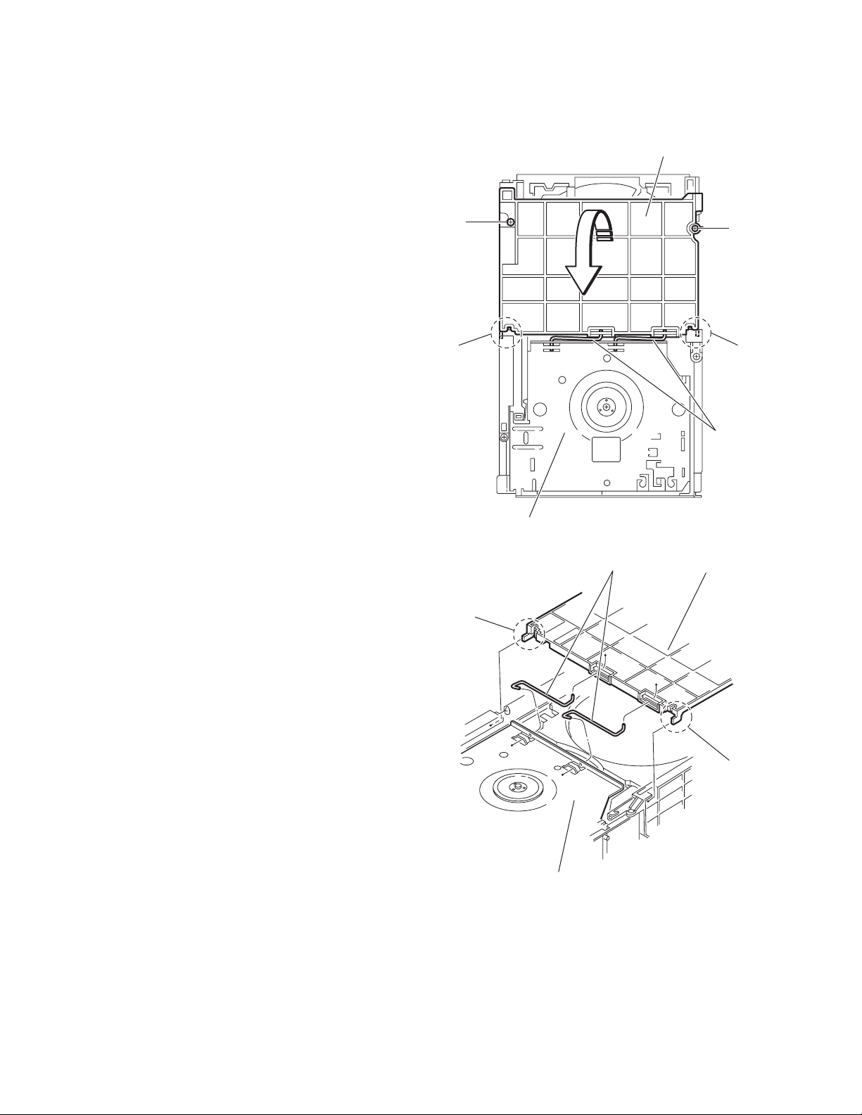
3.2.1 Removing the tray assemblies
(See Figs.1 to 5)
(1) From the top side of the main body, remove the two screws
A from the top cover and release the two joints a on the
both sides of the DVD changer mechanism assembly. (See
Figs.1 and 2.)
(2) Remove the two rods from the top cover and remove the
top cover from the lifter assembly. (See Figs.1 and 2.)
(3) Remove the open det. lever on the left side of the DVD
changer mechanism assembly. (See Fig.3.)
(4) From the right side of the DVD changer mechanism as-
sembly, draw out the tray assemblies toward the front while
pushing the part b of the side (R) assembly. (See Figs.4
and 5.)
Note:
The tray can be locked if all tray assemblies are attached.
(5) From the topside of the DVD changer mechanism assem-
bly, move the stopper tabs c in the direction of the arrow
and release them. Pull out the tray assemblies from the
DVD changer mechanism assembly. (See Fig. 5.)
Note:
Remove the tray assembly from top tray 5 in order.
Reference:
When reattaching the tray assembly, or when removing the
disc remaining inside, refer to another section "3.3.15 Taking
out the disc in the play mode".
A
a
Lifter assembly
Fig.1
Rods
Top cover
A
a
Rods
Top cover
a
a
Lifter assembly
Fig.2
1-24 (No.MB368)
Page 3
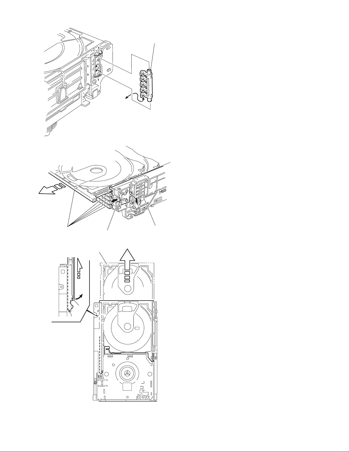
Fig.3
r
Open det. leve
Tray assemblies
c
b
Side(R) assembly
Fig.4
Tray assembly
Fig.5
(No.MB368)1-25
Page 4
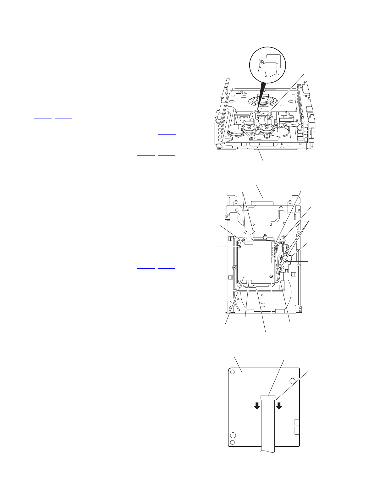
3.2.2 Removing the DVD servo board
(See Figs.6 to 8)
Caution:
Solder the short land sections d on the DVD pickup before disconnecting the card wire extending from the DVD pickup. If
you do not follow this instruction, the DVD pickup may be damaged.
(1) From the topside of the DVD changer mechanism assem-
bly, solder the short land sections d on the DVD pick up.
(See Fig.6.)
(2) From the bottom side of the DVD changer mechanism as-
sembly, disconnect the card wire from the connectors
(CN201
Reference:
(3) Disconnect the wires from the connectors (CN452
on the DVD servo board. (See Fig.7.)
(4) Remove the two screws B attaching the DVD servo board.
(See Fig.7.)
(5) From the reverse side of the DVD servo board, release the
lock of the connector CN101
and disconnect the card wire. (See Fig.8.)
Caution:
Unsolder the solders from the short land sections d after reassembling. (See Fig.6.)
3.2.3 Removing the switch board
(1) From the bottom side of the DVD changer mechanism as-
sembly, remove the screw C attaching the switch board on
the DVD changer mechanism assembly.
(2) Disconnect the wires from the connectors (CN452
on the DVD servo board.
(3) Release the wires from the section f and remove the switch
board.
(4) Release the wires from the sections g and remove the
switch board.
Reference:
When reassembling, pass the wires through the sections (f, g)
as before.
, CN451) on the DVD servo board. (See Fig.7.)
When connecting the card wire to the connector CN451
pass it through the sections e on the DVD traverse
mechanism assembly. (See Fig.7.)
, CN453)
in the direction of the arrow
(See Fig.7)
, CN453)
d
,
DVD changer mechanism assembly
Fig.6
DVD changer mechanism assembly
e
CN451
DVD pickup
CN453
f
g
Switch board
B
C
CN201
DVD servo board
DVD traverse mechanism assembly
DVD servo board
B
Fig.7
CN452
CN101
1-26 (No.MB368)
Lock
Fig.8
Page 5
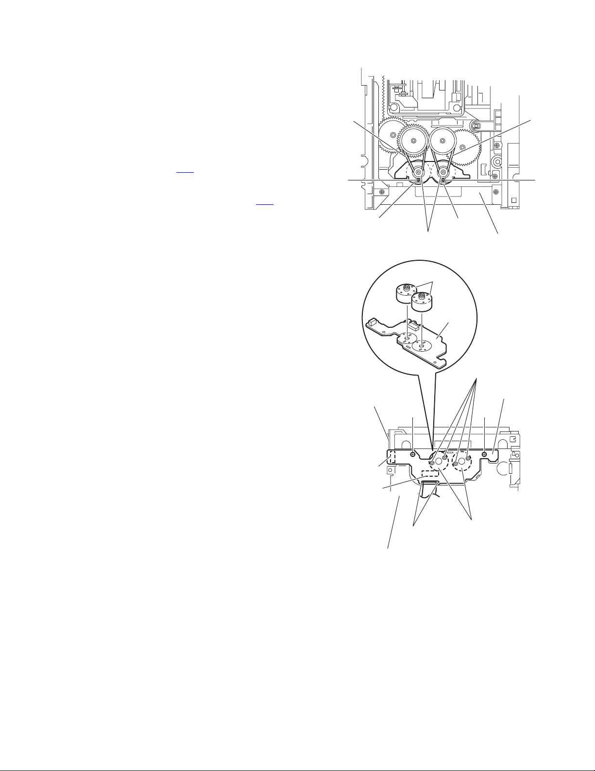
3.2.4 Removing the motor board
(See Figs.9 and 10)
(1) From the top side of the DVD changer mechanism assem-
bly, remove the two belts from the motor pulleys. (See
Fig.9.)
Note:
Take care not to attach grease on the belt.
(2) Remove the two screws D attaching the motors to the load-
er assembly. (See Fig.9.)
(3) From the bottom side of the DVD changer mechanism as-
sembly, remove the two screws E. (See Fig.10.)
(4) Disconnect the connector CN2
tray switch board and remove the motor board. (See
Fig.10.)
(5) Disconnect the card wire from the connector CN1
forward side of the motor board. (See Fig.10.)
Note:
When connecting the card wire, let the card wire through the
slots h of the motor board. (See Fig.10.)
Reference:
You need not to remove the tray assemblies, and in such case,
move it.
3.2.5 Removing the motor
(See Fig. 10)
• Remove the motor board.
(1) From the reverse side of the motor board, unsolder the four
soldered sections i on the motor board.
(2) From the forward side of the motor board, remove the mo-
tors.
on the motor board from the
on the
D
Belt
Motor Motor
Motor pulleys
Belt
D
Loader assembly
Fig.9
Motors
Motor board
i
Tray switch
board
E
CN2
CN1
h
DVD changer mechanism assembly
Fig.10
Motors
Motor board
E
(No.MB368)1-27
Page 6

3.2.6 Removing the DVD traverse mechanism assembly
(See Fig.11)
• Remove the tray assemblies and DVD servo board.
(1) From the bottom side of the DVD changer mechanism as-
sembly, remove the three screws F attaching the DVD
traverse mechanism assembly.
(2) Remove the wires from the section j.
(3) Take out the DVD traverse mechanism assembly from the
DVD changer mechanism assembly.
DVD changer mechanism assembly
F
j
F
F
DVD traverse mechanism assembly
Fig.11
1-28 (No.MB368)
Page 7

3.2.7 Removing the DVD pickup
(See Figs.12 to 14)
• Remove the tray assemblies, DVD servo board and DVD
traverse mechanism assembly.
(1) From the top side of the DVD traverse mechanism assem-
bly, release the lock of the connector on the DVD pickup
and disconnect the card wire in the direction of the arrow.
(See Fig.12.)
(2) Turn the screw shaft gear in the direction of the arrow 1 to
move the DVD pickup in the direction of the arrow 2. (See
Fig.12.)
(3) Remove the screw G attaching the feed bracket and re-
move the feed bracket from the sections k. (See Fig.12.)
(4) Release the claw m of the thrust spring in the direction of
the arrow and remove the thrust spring. (See Fig.12.)
(5) Remove the guide shaft from the sections (n, p) on the
C.TM chassis. (See Fig.13.)
(6) Remove the section q of the DVD pickup. (See Fig.13.)
(7) Remove the two screws H attaching the rack arm spring
and rack arm. (See Fig.14.)
(8) Pull the guide shaft from the DVD pickup in the direction of
the arrow. (See Fig.14.)
3.2.8 Attaching the DVD pickup
(See Figs.12 to 14)
(1) Attach the guide shaft to the DVD pickup and attach the
rack arm spring and rack arm with the screws H. (See
Fig.14.)
(2) Attach the section q of the DVD pickup to the C.TM chassis
first and attach the guide shaft to the sections (n, p). (See
Fig.13.)
Reference:
When attaching the guide shaft to the section p, attach it
under the rod spring. (See Fig.13.)
(3) Attach the thrust spring and feed bracket with the screw G.
(See Fig.12.)
(4) Turn the screw shaft gear in the direction of the arrow 1 to
move the DVD pickup in the direction of the arrow 2. (See
Fig.15.)
(5) Connect the card wire to the connector on the DVD pickup.
(See Fig.15.)
DVD traverse mechanism assembly
Thrust spring
Connector
Screw shaft gear
DVD pickup
Fig.12
DVD pickup
1
k
Thrust spring
q
Feed bracket
2
G
m
p
Rod spring
n
Guide shaft
C.TM chassis
Fig.13
(No.MB368)1-29
Page 8

Guide shaft
DVD pickup
Rack arm
H
Rack arm spring
Fig.14
Connector
DVD pickup
222
Screw shaft gear
Fig.15
1
1-30 (No.MB368)
Page 9

3.2.9 Removing the spindle motor board
(See Figs.16 and 17)
• Remove the tray assemblies, DVD servo board and DVD
traverse mechanism assembly.
(1) From the top side of the DVD traverse mechanism assem-
bly, remove the wires from the soldered sections r on the
spindle motor board. (See Fig.16.)
(2) From the bottom side of the DVD traverse mechanism as-
sembly, remove the three screws J attaching the spindle
motor board. (See Fig.17.)
Reference:
When attaching the spindle motor board, let the card wire
through the hole s on the C.TM chassis. (See Fig.17.)
DVD traverse mechanism assembly
Spindle motor board
r
Fig.16
DVD traverse mechanism assembly
s
J
C.TM chassis
Fig.17
(No.MB368)1-31
Page 10

3.2.10 Removing the feed motor
(See Figs.18 and 19)
• Remove the tray assemblies and DVD traverse mechanism
assembly.
(1) From the top side of the DVD traverse mechanism assem-
bly, remove the screw K attaching the feed bracket and remove the feed bracket from the sections t. (See Fig.18.)
(2) Release the claw u of the thrust spring in the direction of
the arrow and remove the thrust spring. (See Fig.18.)
(3) Remove the screw shaft from the section v and remove it
in the direction of the arrow. (See Fig.19.)
(4) Remove the middle gear. (See Fig.19.)
(5) Remove the screw L attaching the feed motor to the C.TM
chassis. (See Fig.19.)
(6) Remove the wires from the soldered sections w on the
spindle motor board. (See Fig.19.)
(7) Take out the feed motor from the motor base.
Reference:
After attaching the feed motor, pass the wires through the sections x on the C.TM chassis as before. (See Fig.19.)
Feed bracket
Thrust spring
K
t
Thrust spring
Spindle motor board
w
x
Fig.18
Middle gear
v
Screw shaft
u
C.TM chassis
1-32 (No.MB368)
L
Fig.19
Page 11

3.2.11 Removing the side (L) and tray switch board
(See Figs.20 to 22)
• Remove the tray assemblies.
(1) From the topside of the DVD changer mechanism assem-
bly, remove the two screws M attaching the side (L). (See
Fig.20.)
(2) From the left side of the DVD changer mechanism assem-
bly, disconnect the connector CN3
from the motor board and detach the side (L) in an upward
direction. (See Fig.21.)
(3) Remove the screw N attaching the tray switch board to the
side (L). (See Fig.22.)
(4) Release the joint tab y of the side (L) in the direction of the
arrow 1 and release the joint tab z while removing the tray
switch board in the direction of the arrow 2. (See Fig.22.)
on the tray switch board
SIde(L)
M
M
DVD changer mechanism assembly
Fig.20
M
Side(L)
M
CN3
Tray switch board
Motor board
Side(L)
Fig.21
y
1
Tray switch board
Fig.22
2
z
N
(No.MB368)1-33
Page 12

3.2.12 Removing the side (R) assembly
(See Fig.23 to 27)
• Remove the tray assemblies and DVD servo board.
(1) From the inside of the side (R) assembly, release the two
tabs aa of the gear cover and remove the gear cover outward. (See Figs.23 and 24.)
(2) From the right side of the DVD changer mechanism as-
sembly, remove the elevator spring attached to the hook
ab of the loader assembly. (See Figs.24 and 25.)
(3) From the top side of the DVD changer mechanism assem-
bly, turn the gear 1 clockwise to move the elevator cam
rearward. (See Fig.25.)
(4) Move the two slots ac and joint ad of the elevator cam and
remove the elevator cam outward. (See Fig.25.)
(5) Remove the three screws P and detaches the side (R) as-
sembly upward. (See Figs.26 and 27.)
Note:
When reattaching the side (R) assembly, make sure to fit the
shaft (part ae) into the slot of the select lever. (See Fig.26.)
Side(R) assembly
aa
P
Elevator spring
ac
Fig.25
P
ae
ab
Elevator cam
acad
Select lever
Side(R) assembly
Gear cover
Loader assembly
P
Fig.23
Elevator spring
Gear 1
Side(R) assembly
Fig.26
P
ab
P
Fig.24
Side(R) assembly
Fig.27
1-34 (No.MB368)
Page 13

3.2.13 Removing the lifter assembly
(See Figs.28 to 32)
• Remove the tray assemblies, DVD servo board, side (L) and
side (R) assembly.
(1) (1) From the top side of the DVD changer mechanism as-
sembly, turn the gear 1 clockwise to move the lifter assembly upward. (See Figs.28 and 29.)
(2) Turn the gear 2 clockwise to move the hook toward the
front until it stops. (See Figs.28 and 29.)
(3) Move the hook stopper in the direction of the arrow 2 while
pushing the tab af of the hook stopper to unlock it in the direction of the arrow 1 and release four joints ag to detach
from the rack holder. (See Fig.30.)
(4) Release the rod (L) from part ah. (See Fig.30.)
(5) Turn the gear 1 clockwise again to move the lifter assembly
upward. (See Fig.31.)
(6) Remove the lifter assembly from the DVD changer mecha-
nism assembly upward at the positions ai where the four
pins on the both sides of the lifter assembly fit to the notch-
es of the loader assembly. (See Fig.31.)
(7) Move the lifter assembly in the direction of the arrow and
release it from the hook. (See Fig.32.)
Hook stopper
Gear 2
Gear 1
ag
Rack holder
af
Hook
ag
1
ag
Hook stopper
Fig.30
Lifter assembly
ag
2
Rod(L)
ai
ah
ai
Hook
Gear 2
Lifter assembly
Fig.28
Gear 1
Lifter assembly
Gear 1
ai
Loader assembly
Fig.31
Lifter assembly
ai
Hook stopper
Hook
Fig.32
Hook
Fig.29
(No.MB368)1-35
Page 14

3.2.14 Removing the sensor board and SV resistor
(See Fig.33)
• Remove the tray assemblies, side (L), side (R) assembly and
lifter assembly.
(1) Remove the solders from the soldered sections aj on the
sensor board and remove the wires.
(2) Remove the two screws Q and take out the sensor board
with the SV resistor.
Reference:
• Remove the soldered section ap on the sensor board as required.
• When reassembling, pass the wires through the slot ak of
the sensor board as before.
Note:
When reattaching the SV. resister, fit the projection am on the
bottom of the SV. resister into slot an of the sensor slider.
Sensor board
Q
ap
Q
ak
aj
SV resistor
am
an
SV resistor
Slider
Fig.33
1-36 (No.MB368)
Page 15

3.2.15 Taking out the disc in the play mode
(See Fig.34 to 37)
Reference:
Refer to "3.3.1 Removing the tray assemblies".
(1) From the top side of the DVD changer mechanism assem-
bly, remove the top cover.
(2) Unlock the tray assemblies and draw out the tray assem-
blies toward the front.
(3) From the top side of the DVD changer mechanism assem-
bly, turn the gear 1 clockwise to move the lifter assembly
upward. (See Fig.34.)
(4) Turn the gear 2 clockwise to move the sub tray remaining
inside the lifter assembly toward the front, then pull out.
(See Fig.34.)
(5) Take out the disc on the sub tray. (See Fig.35.)
(6) After clearing away the disc, insert the sub tray into the
main tray. (See Fig.36.)
Note:
When reattaching the sub tray, move the tray stopper on
the bottom of the main tray in the direction of the arrow
to lock the sub tray certainly. (See Figs.36 and 37.)
(7) Push the tray assembly toward the DVD changer mecha-
nism assembly and reattach.
Tray assembly
Gear 2
Gear 1
Sub tray
Fig.34
Tray assembly
Fig.35
Disc
Sub tray
(No.MB368)1-37
Page 16

Tray stopper
r
Main tray
Sub tray
Fig.36
Tray stoppe
1-38 (No.MB368)
Fig.37
 Loading...