

Page 1
PROJECTOR
MANUEL D’INSTRUCTIONS : PROJECTEUR
DLA-L20U
For customer Use:
Enter below the Serial No. which is located
on the side panel of the cabinet. Retain this
information for future reference.
INSTRUCTIONS
ENGLISHFRANÇAIS
Pour l’utilisateur:
Inscrivez ci-dessous le No de série situé sur
le panneau latéral du coffret de l’appareil.
Conservez cette information à titre
d’information.
Model No.
No de modèle DLA-L20U
Serial No.
No de série
OPERATE
COMPUTER VIDEO
VOL.
ZOOM FOCUS
PAGE
BACK
PRESET
QUICK
ALIGN.AVMUTING
RM-M10G REMOTE CONTROL UNIT
T
W
MENU/ENTER
Page 2
INSTRUCTIONS
PROJECTOR
DLA-L20U
ENGLISH
1
Page 3
Thank you for purchasing this projector. Before using it, read and follow all instructions carefully to take full
advantage of the projector's capabilities.
SAFETY PRECAUTIONS
IMPORTANT INFORMATION
WARNING :
TO PREVENT FIRE OR SHOCK HAZARDS, DO NOT
EXPOSE THIS APPLIANCE TO RAIN OR MOISTURE.
CAUTION :
To reduce the risk of electric shock, do not remove cover.
Refer servicing to qualified service personnel.
This projector is equipped with a 3-blade grounding-type
plug to satisfy FCC rule. If you are unable to insert the
plug into the outlet, contact your electrician.
FCC INFORMATION (U.S.A. only)
CAUTION: Changes or modification not approved by
JVC could void the user's authority to operate the
equipment.
NOTE: This equipment has been tested and found to
comply with the limits for a Class A digital device,
pursuant to Part 15 of the FCC Rules. These limits
are designed to provide reasonable protection against
harmful interference when the equipment is operated
in a commercial environment. This equipment
generates, uses, and can radiate radio frequency
energy and, if not installed and used in accordance
with the instruction manual, may cause harmful
interference to radio communications. Operation of
this equipment in a residential area is likely to cause
harmful interference in which case the user will be
required to correct the interference at his own
expense.
About burning-in of the D-ILA device
Do not allow the same still picture to be projected for a long
time or an abnormally bright video picture to be projected.
Do not project video images with high-intensity or highcontrast on a screen. The video image could be burned in
to the D-ILA device.
Use special care when projecting video games or computer
program images. There is no problem with ordinary videocassette playback images.
About the installation place
Do not install the projector in a place that can not support its
weight securely.
If the installation place is not sturdy enough, the projector
could fall or overturn, possibly causing personal injury.
IMPORTANT SAFEGUARDS
Electrical energy can perform many useful functions. This
unit has been engineered and manufactured to assure
your personal safety. But IMPROPER USE CAN RESUL T
IN POTENTIAL ELECTRICAL SHOCK OR FIRE
HAZARD. In order not to defeat the safeguards
incorporated into this product, observe the following basic
rules for its installation, use and service. Please read these
“Important Safeguards” carefully before use.
– All the safety and operating instructions should be read
before the product is operated.
– The safety and operating instructions should be retained
for future reference.
– All warnings on the product and in the operating
instructions should be adhered to.
– All operating instructions should be followed.
– Unplug this product from the wall outlet before cleaning.
Do not use liquid cleaners or aerosol cleaners. Use a
damp cloth for cleaning.
– Do not use attachments not recommended by the
product manufacturer as they may be hazardous.
– Do not use this product near water. Do not use
immediately after moving from a low temperature to high
temperature, as this causes condensation, which may
result in fire, electric shock, or other hazards.
– Do not place this product on an unstable cart, stand, or
table. The product may fall, causing serious injury to a
child or adult, and serious damage to the product. The
product should be mounted according to the
manufacturer’s instructions, and should use a mount
recommended by the manufacturer.
– When the product is used on a cart, care
should be taken to avoid quick stops,
excessive force, and uneven surfaces
which may cause the product and cart to
overturn, damaging equipment or causing
possible injury to the operator.
– Slots and openings in the cabinet are provided for
ventilation. These ensure reliable operation of the
product and protect it from overheating. These openings
must not be blocked or covered. (The openings should
never be blocked by placing the product on bed, sofa,
rug, or similar surface. It should not be placed in a built-
in installation such as a bookcase or rack unless proper
ventilation is provided and the manufacturer’s
instructions have been adhered to.)
For proper ventilation, separate the product from other
equipment, which may prevent ventilation and keep
distance more than 60 cm (23-5/8”).
2
Page 4

SAFETY PRECAUTIONS (Cont.)
– This product should be operated only with the type of
power source indicated on the label. If you are not sure
of the type of power supply to your home, consult your
product dealer or local power company.
– This product is equipped with a three-wire plug. This
plug will fit only into a grounded power outlet. If you are
unable to insert the plug into the outlet, contact your
electrician to install the proper outlet. Do not defeat the
safety purpose of the grounded plug.
– Power-supply cords should be routed so that they are
not likely to be walked on or pinched by items placed
upon or against them. Pay particular attention to cords
at doors, plugs, receptacles, and the point where they
exit from the product.
– For added protection of this product during a lightning
storm, or when it is left unattended and unused for long
periods of time, unplug it from the wall outlet and
disconnect the cable system. This will prevent damage
to the product due to lightning and power line surges.
– Do not overload wall outlets, extension cords, or
convenience receptacles on other equipment as this can
result in a risk of fire or electric shock.
– Never push objects of any kind into this product through
openings as they may touch dangerous voltage points
or short out parts that could result in a fire or electric
shock. Never spill liquid of any kind on the product.
– Do not attempt to service this product yourself as opening
or removing covers may expose you to dangerous
voltages and other hazards. Refer all service to qualified
service personnel.
– Unplug this product from the wall outlet and refer service
to qualified service personnel under the following
conditions:
a) When the power supply cord or plug is damaged.
b) If liquid has been spilled, or objects have fallen on
the product.
c) If the product has been exposed to rain or water.
d) If the product does not operate normally by following
the operating instructions. Adjust only those controls
that are covered by the Operation Manual, as an
improper adjustment of controls may result in damage
and will often require extensive work by a qualified
technician to restore the product to normal operation.
e) If the product has been dropped or damaged in any
way.
f ) When the product exhibits a distinct change in
performance – this indicates a need for service.
– When replacement parts are required, be sure the service
technician has used replacement parts specified by the
manufacturer or with same characteristics as the original
part. Unauthorized substitutions may result in fire, electric
shock, or other hazards.
– Upon completion of any service or repairs to this product,
ask the service technician to perform safety checks to
determine that the product is in proper operating
condition.
– The product should be placed more than one foot away
from heat sources such as radiators, heat registers,
stoves, and other products (including amplifiers) that
produce heat.
– When connecting other products such as VCR’s, and
personal computers, you should turn off the power of
this product for protection against electric shock.
– Do not place combustibles behind the cooling fan. For
example, cloth, paper, matches, aerosol cans or gas
lighters that present special hazards when over heated.
– Do not look into the projection lens while the illumination
lamp is turned on. Exposure of your eyes to the strong
light can result in impaired eyesight.
– Do not look into the inside of this unit through vents
(ventilation holes), etc. Do not look at the illumination
lamp directly by opening the cabinet while the illumination
lamp is turned on. The illumination lamp also contains
ultraviolet rays and the light is so powerful that your
eyesight can be impaired.
– Xenon gas is enclosed with high pressure inside the light-
source lamp (lamp unit) of this projector. If you drop or
impart a shock to the lamp, or discard it as is, there is
the possibility of explosion, leading to personal injury.
Use special care when handling the lamp. For any
unclear points, consult your product dealer.
– Do not “ceiling-mount” the projector to a place which
tends to vibrate; otherwise, the attaching fixture of the
projector could be broken by the vibration, possibly
causing it to fall or overturn, which could lead to personal
injury.
– Use only the accessory cord designed for this product to
prevent shock.
The power supply voltage rating of this product is AC
120 V, the power cord attached conforms to the
following power supply voltage. Use only the power
cord designated by our dealer to ensure Safety and
EMC.
When it is used by other power supply voltage, power
cable must be changed.
Consult your product dealer.
Power cord
Power supply voltage: AC 120 V
*DO NOT allow any unqualified person to
install the unit.
Be sure to ask your dealer to install the unit
(e.g. attaching it to the ceiling) since special technical
knowledge and skills are required for installation.
If installation is performed by an unqualified person, it
may cause personal injury or electrical shock.
ENGLISH
3
Page 5

Contents
SAFETY PRECAUTIONS........................... 2
Accessories ............................................... 5
Controls and Features .............................. 6
Front Side / Top Surface / Right Side....................6
Left-hand side .......................................................7
Bottom Surface .....................................................8
Control Panel ........................................................9
Connector Panel ................................................. 11
Remote Control Unit ........................................... 13
Installing Batteries............................................... 14
Installing the Projector ........................... 15
Precautions for Installation.................................. 15
Projection Distance and Screen Size.................. 16
Setting the Amount of Lens Shifting.................... 17
Effective Range and Distance of the Remote
Control Unit ....................................................18
Setting the Position Selecting Screw
for Ceiling Mounting .......................................18
Connecting to Various Devices.............. 19
Signals that Can Be Input to the Projector..........19
Connecting to Video Devices..............................20
Connecting to Hi-Vision Devices......................... 20
Connecting to Other Devices .............................. 21
Connecting to Devices which Control the
Projector.........................................................21
Connecting to Computer Devices .......................22
Connecting the Power Cord (Supplied) .............. 24
When Turning On the Devices Connected to
the Projector...................................................25
Operating the Setting Menu ................... 32
Making Basic Settings......................................... 32
Operating the Main Menu ....................... 33
Configuration of the Main Menu..........................33
Operating the Main Menu (Basic Operation of
the Main Menu) ..............................................35
Changing the Color System ................................ 36
Changing the Language Display.........................37
Adjusting the Pixel Clock .................................... 38
Adjusting the Screen Position ............................. 39
Adjusting Picture Quality.....................................40
Adjusting Sound Quality...................................... 43
Setting and Adjusting Other Functions
(OPTIONS) .................................................... 44
Changing (Setting) the Source............................ 47
Setting Up Channels ........................................... 49
Changing Channels ............................................ 54
Setting up (or Changing) User Sources .............. 56
Setting up or Changing the Display Size ............59
Replacing the Fuse ................................. 60
Replacing the Light-Source Lamp......... 61
Resetting the Lamp Use Time.............................63
Cleaning and Replacing the Filter ......... 64
Troubleshooting ...................................... 65
Specifications.......................................... 67
Appendix.................................................. 71
Basic Operations..................................... 26
1. Turning on the Power...................................... 26
2. Select the Video Input to be Projected............ 27
3. Adjust the Screen Size .................................... 27
4. Adjust focus.....................................................28
5. Adjust sound volume....................................... 28
• For Operating Other Functions .........................29
*This manual is divided into two language sections:
English and French.
4
Page 6
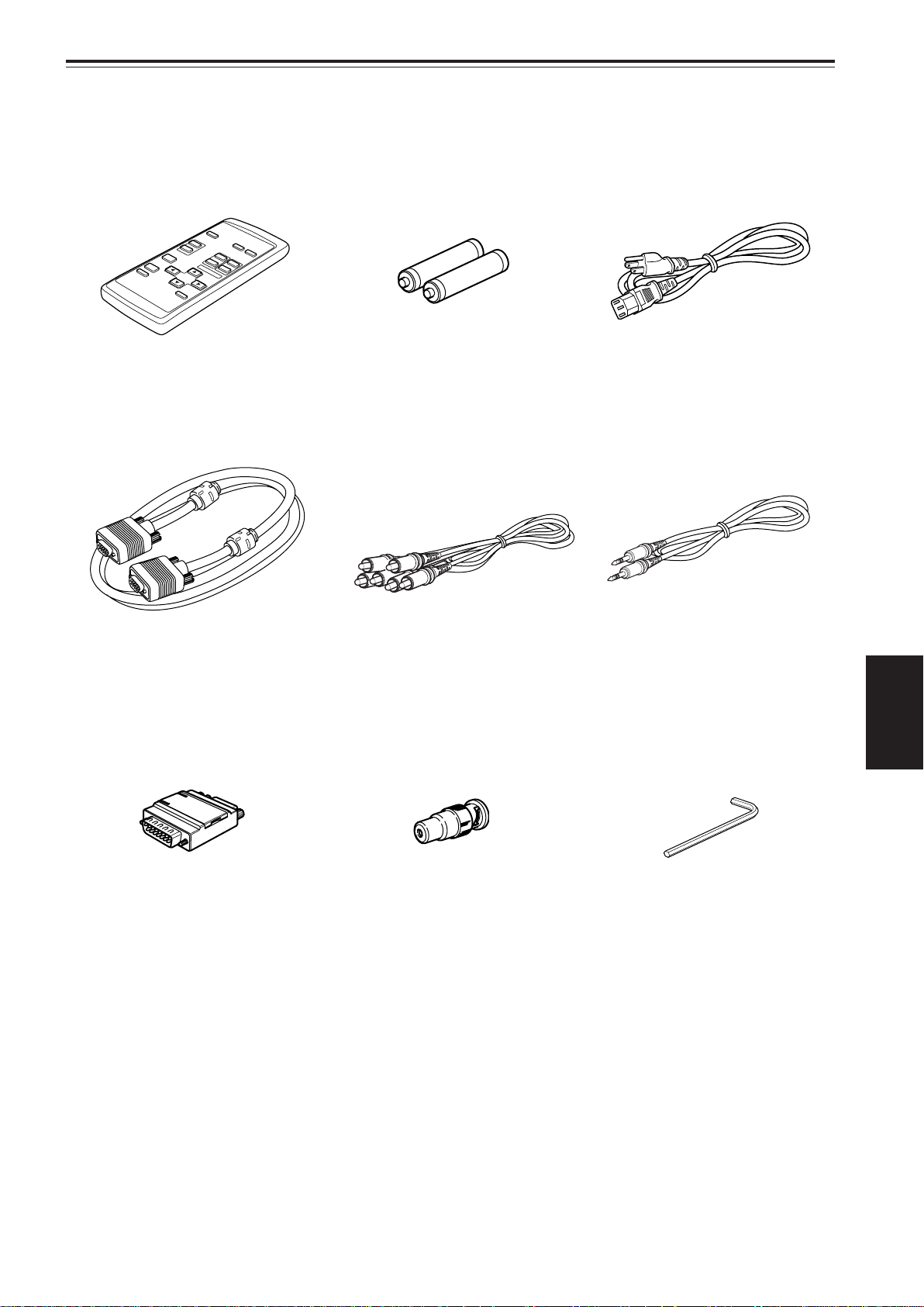
Accessories
The following accessories are included with this projector. Check for them; if any item is missing, please contact your
dealer.
Remote control unit (RM-M10G) AAA/R03-size dry cell battery (×2)
Personal computer connection cable
[approx. 2 m (6.56 ft)]
(D-sub, 3-row 15 pin)
(for checking operation)
AV connection cable
[approx. 1.5 m (4.92 ft)]
Power cord
[approx. 2.5 m (8.2 ft)]
Audio cable
[approx. 3 m (9.84 ft)]
(3.5 mm dia. stereo mini plug)
ENGLISH
Conversion adapter for Mac
(for Macintosh)
BNC-RCA conversion plug
Hex wrench
5
Page 7
lever
Y
P
C
A
U
D
I
O
A
U
D
I
O
A
U
D
I
O
A
U
D
I
O
O
U
T
R
E
M
O
T
E
Y
P
B
/
B
-
Y
P
R
/
R
-
Y
L
R
H
/
C
S
V
R
G
B
C
O
M
P
U
T
E
R
O
U
T
R
S
-
2
3
2
C
Y
/
C
V
I
D
E
O
+7°
Controls and Features
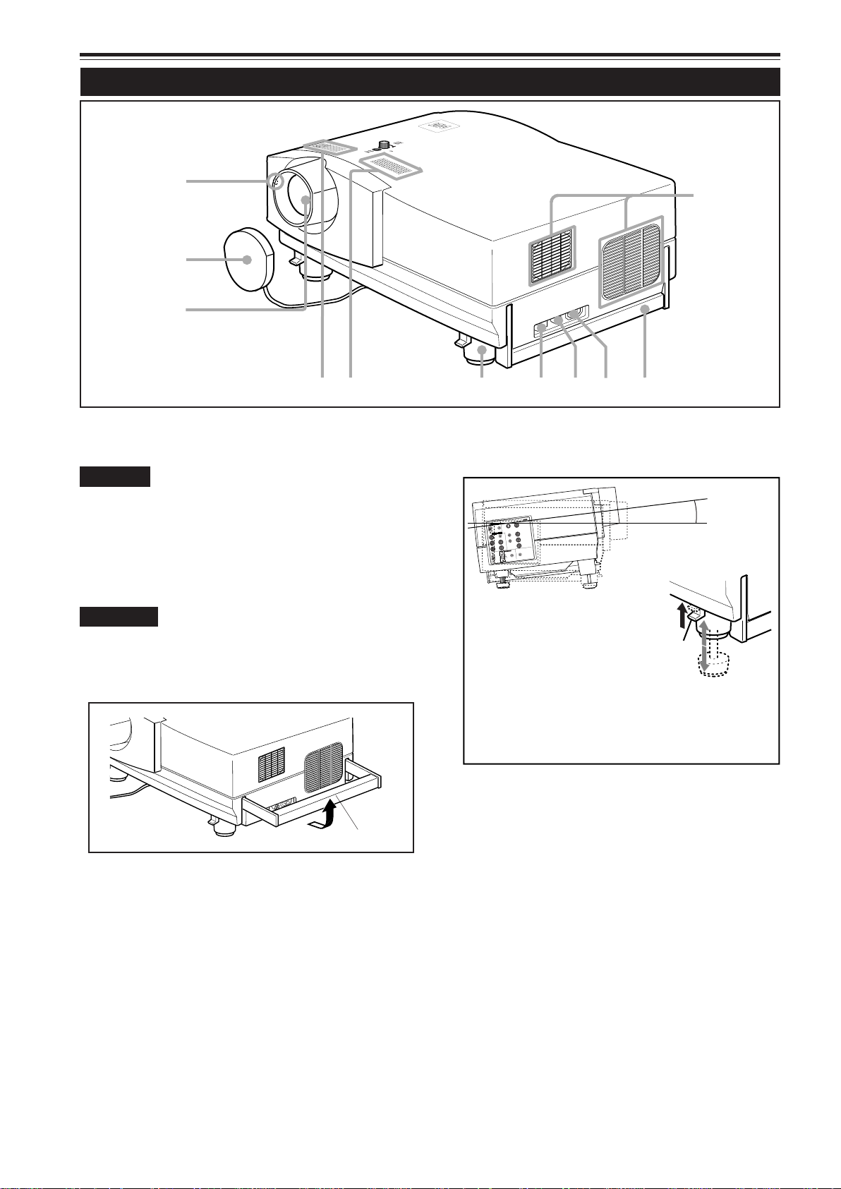
Front Side / Top Surface / Right Side
Y
C
N
P
E
G
M
E
R
T
E
P
M
M
A
L
E
T
A
R
E
P
O
Y
B
D
N
A
T
S
E
q
p
9
8
7
Exhaust vents
1
Vents for cooling fans through which warm air comes out.
CAUTION
• Do not block the exhaust vents, or heat builds up inside,
possibly causing a fire. Also, do not touch the vents, or this
could cause a low-temperature burn.
Carrying handle
2
Raise this handle when carrying the projector.
CAUTIONS
• When carrying the projector, do not give a shock to it. Be
careful to keep its balance.
• Do not carry it while the light source lamp is on or the cooling
fan is operating. This could cause personal injury.
How to use the carrying handle
1
4
56
Adjustable foot (for horizontal angle adjustment)
6
By extending the feet, the projector angle can be adjusted
up to +7°.
• Extending the front
adjustable foot
While pushing the lever,
raise the projector, and
the adjustable foot extends
automatically.
To retract the foot, pushing
the lever, lower the projector slowly;
the projector is fixed at the position where you
release the lever.
3
2
Built-in speaker (left)
7
Built-in speaker (right)
Carrying handle
AC IN (power input) terminal
3
This is the power input terminal where the supplied power
cord is connected. For details, refer to page 24.
Fuse holder
4
A fuse rated 15 A/250 V is installed. (Power source
protection)
To replace the fuse, use a fuse with the same
specifications.
MAIN POWER switch
5
This is the main power switch. When it is turned on, the
projector goes into stand-by state, and the STAND BY
indicator on the control panel comes on.
8
Lens
9
The projection lens used in this projector is a long focaldistance zoom lens (1.9 x zoom lens for 2.9:1 to 5.5:1)
with manual shift function. Before projection, remove the
lens cap.
Lens cap
p
The cap has a string attached and the string is fixed to the
projector when shipped from the factory . It is recommended
that the cap be fitted on to prevent the lens becoming dirty
when the projector is not used.
Remote sensor
q
When operating with the remote control, aim it toward this
sensor.
ON [ ❙ ]: The main power turns on.
‡‡
OFF [
‡]: The main power turns off.
6
‡‡
Page 8
Controls and Features (Cont.)
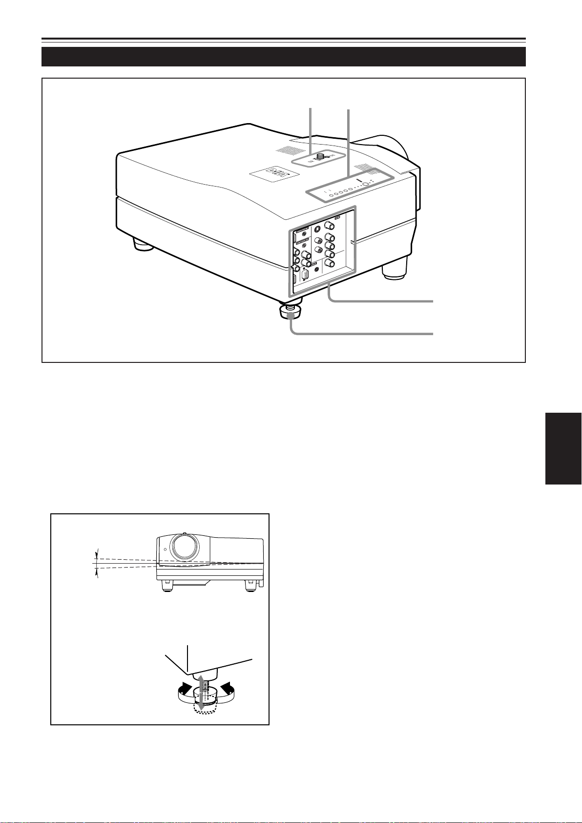
Left-hand side
Control panel
w
For details, refer to “Control Panel” on page 9.
Connector panel
e
For details, refer to “Connector Panel” on page 11.
Adjustable foot (for horizontal angle adjustment)
r
It is set at the shortest position when shipped from the
factory. Turn the foot to make the projector level. Adjustment
can be made in the range of + 1.5° and – 1.5° from the
horizontal position.
t
w
UP
D
O
W
N
S
T
A
N
D
B
Y
L
E
A
M
M
E
T
P
R
E
G
M
E
P
N
C
V
Y
C
I
D
O
E
M
O
P
U
T
S
E
E
R
T
T
IN
Q
A
U
G
L
I
C
I
G
K
+
N
3
.
-
2
e
r
LENS SHIFT knob / SHIFT LOCK fixing bolt
t
The projection screen can be shifted up and down in
position. Use this adjustment when you use a different
installation configuration which requires the lens to be
shifted. The amount of lens shift can range from approx.
30% to 55%. For more information, refer to “Setting the
Amount of Lens Shifting” on page 17.
ENGLISH
+1.5°
–1.5°
•How to extend the adjustable foot on the rear
While raising the projector,,
turn the adjustable foot to
the right to extend it.
Extend
Shorten
7
Page 9
Controls and Features (Cont.)
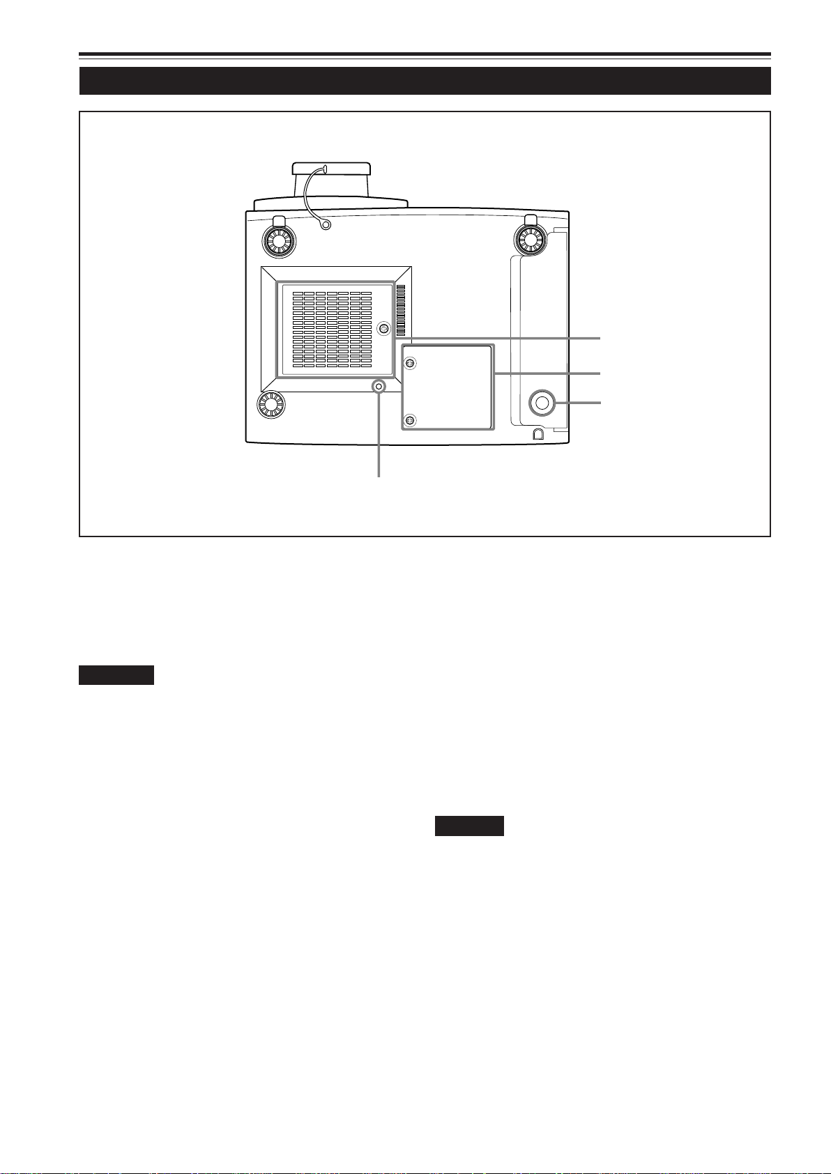
Bottom Surface
y
u
i
o
Air intake area (filter)
y
Air is taken in through this area to cool the light-source
lamp. If this area is blocked or if something that obstructs
taking in or exhausting air is placed around the projector,
heat may build up inside and could cause a fire. For details,
refer to “Precautions for Installation” on page 15.
CAUTIONS
• Be careful as paper, cloth or soft cushion could be drawn in
if placed nearby. Do not block the intake area, or heat may
build up and could cause a fire.
• Clean the filter periodically. For details, refer to “Cleaning
and Replacing the Filter” on page 64.
Deposition of dirt on the filter works to reduce the cooling
effect, causing heat to build up inside, which could cause a
fire or malfunction.
Opening for replacing the light-source lamp
u
For replacing the light-source lamp, refer to “Replacing the
Light-Source Lamp” on page 61.
Fixing foot
i
Position selecting screw for ceiling mounting
o
When using the projector in an upside-down, ceilingmounted position (inverted top-to-bottom and right-to-left),
the “position selecting screw for ceiling mounting” must be
turned to switch to ceiling mounting.
This will correct variance in color images (shading), which
otherwise would occur in ceiling mounting.
For more information, refer to “Setting the Position
Selecting Screw for Ceiling Mounting” on page 18.
CAUTION
• To ceiling-mount and adjust the projector, special expertise
and technique are necessary. Be sure to ask your dealer or
a specialist to perform this work.
8
Page 10
Controls and Features (Cont.)
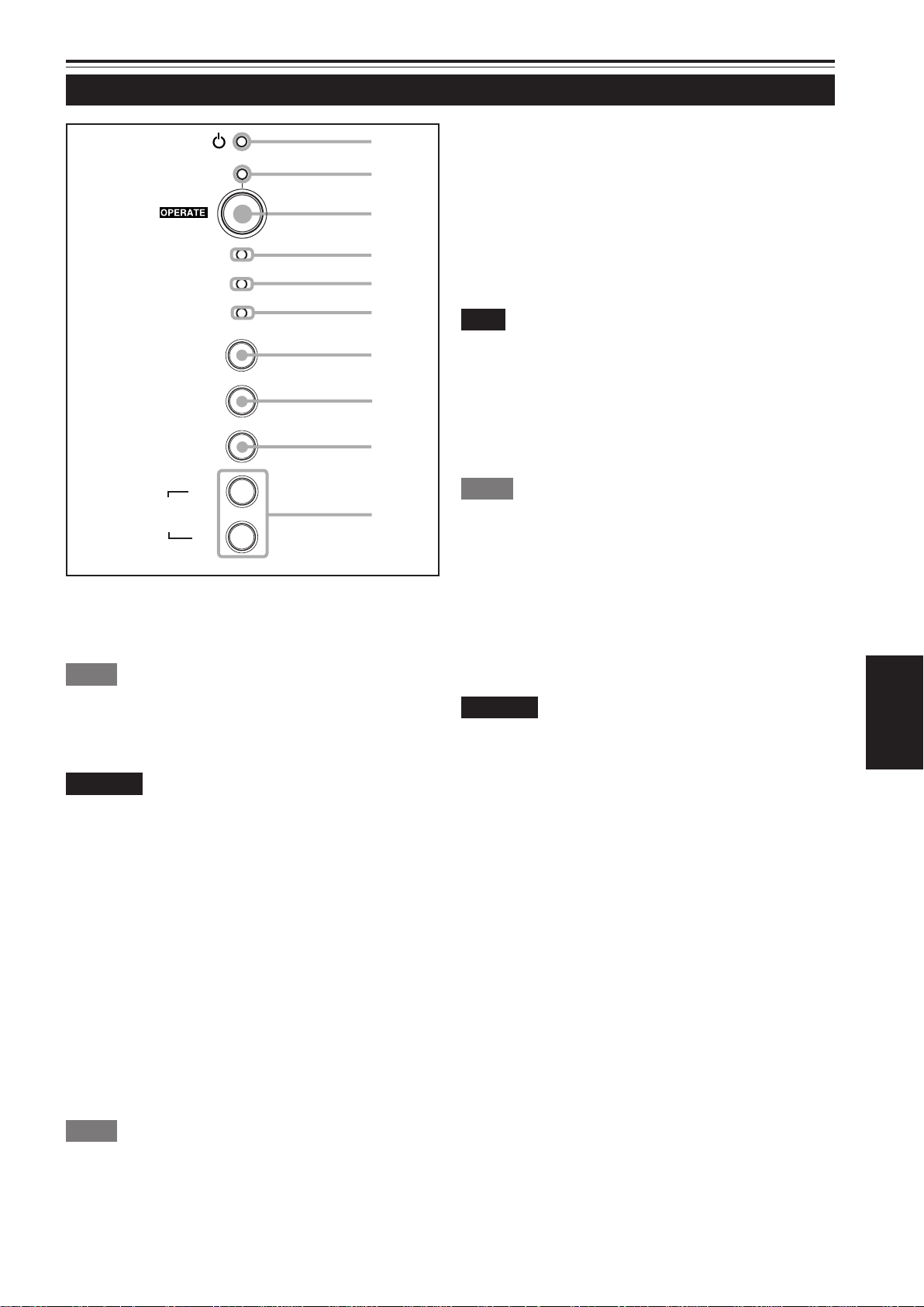
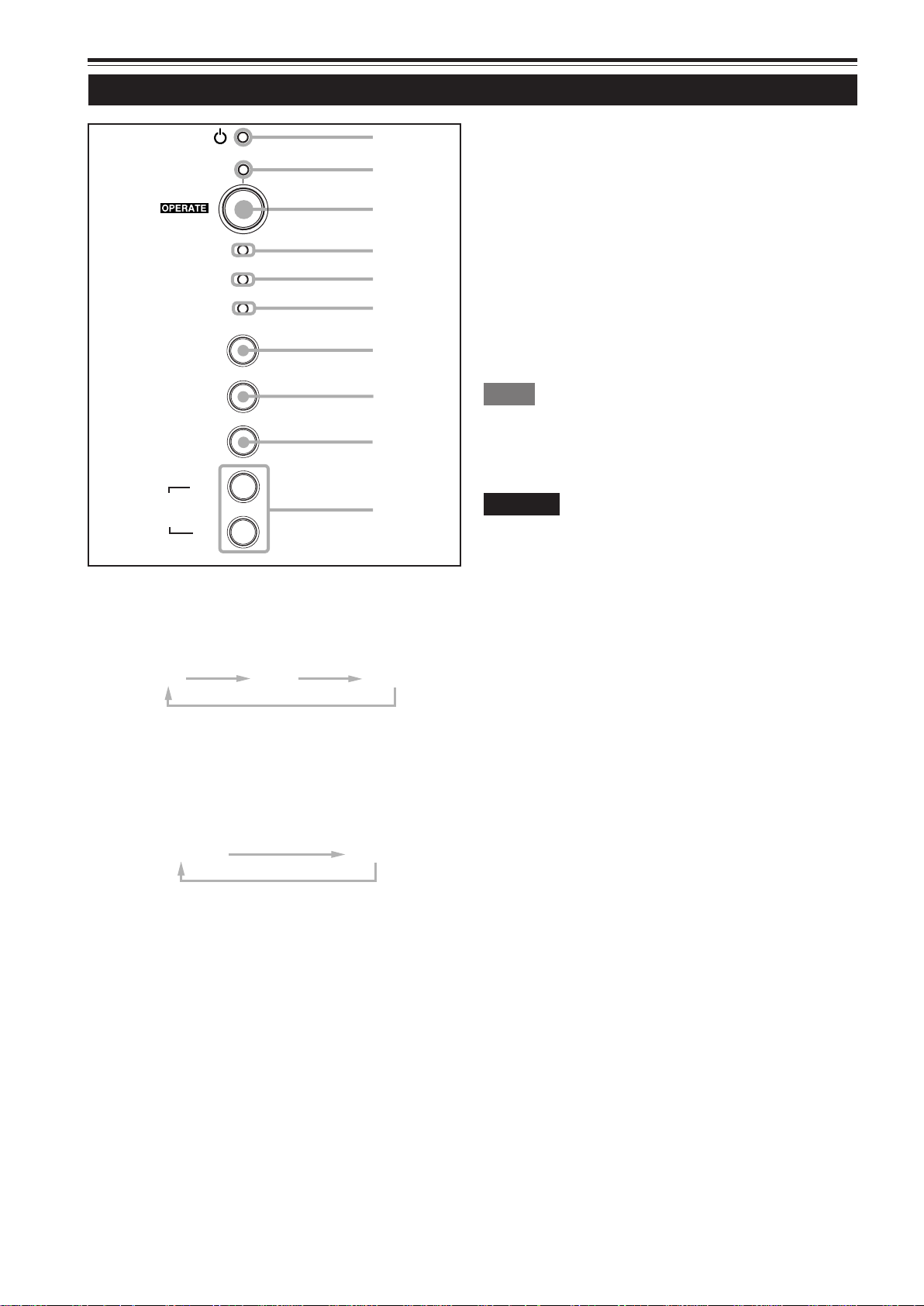
Control Panel
STAND BY
LAMP
TEMP
1
2
3
4
5
Lamp indicator
4
ON : After the light-source lamp has been used for
more than approx. 900 hours.
Blinking : Replace the lamp. Refer to “Replacing the Light-
Source Lamp” on page 61.
TEMP indicator
5
ON: The temperature inside the projector has abnormally
risen.
EMERGENCY
VIDEO
COMPUTER
SETTING
3
+
QUICK
ALIGN.
STAND BY Indicator
1
ON : When in stand-by mode.
Blinking: When in cool-down mode.
Memo
About the cool-down mode:
This projector has a function to cool down the heated lamp for a fixed
period of time (approx. 120 seconds) after projection is finished. This
feature is referred to as the cool-down mode.
CAUTION
• The purpose of the cool-down mode is to prevent inner parts
from being deformed or broken by heat from the heated lamp
as well as to prolong the life of the lamp. Do not turn off the
main power switch while in the cool-down mode. Also, do
not place the projector on its side or stand it upright; this may
block the exhaust vents.
2
-
6
7
8
9
p
Note
• While the TEMP indicator is on (during abnormal temperature), the
power is automatically cut off, and an emergency mode is shown
(with the EMERGENCY indicator blinking).
EMERGENCY indicator
6
Blinking: Something abnormal has occurred with the
projector.
Memo
About the emergency mode:
The emergency mode is shown when the following anomalies have
occurred with the projector (the EMERGENCY indicator blinks). In
the emergency mode, projection is automatically interrupted and the
cooling fans operate for about 20 seconds.
• When the air filter is displaced.
• When the filter is clogged.
• When the light-source lamp has suddenly gone off.
• When the fans have stopped.
• When the temperature inside has risen abnormally high.
• When the AC power supply is suddenly cut or interrupted.
CAUTION
• When an emergency mode is shown:
After the cooling fans have stopped, turn off the main power
switch and unplug the power cord from the wall outlet.
Make sure the lamp-replacement cover and the air filter are
correctly installed. Then, plug in the power cord again and
operate the projector.
If it goes into an emergency mode again, after the cooling
fans have stopped, turn off the main power switch, unplug
the power cord, and call your dealer for repair.
ENGLISH
OPERATE indicator
2
ON: When the projector is in operation (projecting)
OPERATE button
3
When the projector is in the stand-by mode, press this
button one second or more, and the main power switch is
turned on, causing the OPERATE indicator to light. Press
it one second or more again, and the projector goes into
the cool-down mode, then stand-by mode.
Memo
While in the cool-down mode:
If you press the OPERATE button, the projector is not turned on.
9
Page 11
Controls and Features (Cont.)
Control Panel (Cont.)
STAND BY
LAMP
TEMP
EMERGENCY
VIDEO
1
2
3
4
5
6
7
QUICK ALIGN. buttons
p
While a menu screen is shown, use this button to adjust
the values for the item selected. When no menu is shown,
the quick alignment function works.
• When a menu is shown
+ 3 button: The value for the selected item increases.
– 2 button: The value for the selected item decreases.
• When no menu is shown
Press the +3 button and –2 button at the same time:
QUICK-ALIGNMENT is displayed on the screen and the
quick alignment function works (TRACKING, PHASE, H.
POS. and V . POS. are automatically adjusted). When the
adjustment is finished, the display goes off automatically .
COMPUTER
SETTING
3
+
QUICK
ALIGN.
VIDEO button
7
Use this button to select a device such as a VCR connected
to the AV IN terminal of the projector. Each time you press
the button, the device selected changes as follows:
COMPUTER button
8
Use this button to select a device connected to the
COMPUTER -1 or -2 terminals. Each time you press the
button, the selection changes as follows:
Y/C
2
-
VIDEO
8
9
p
YPBPR
Memo
The quick alignment function :
• Works for computer input (COMPUTER-1 and -2 input terminals)
signals.
• Does not work for video input (AV IN input terminal) signals.
CAUTION
• Automatic adjustment with the quick alignment function
should be done on a bright still-picture screen. This function
may not work correctly on a dark screen or motion-picture
screen. If adjustment with this function is not satisfactory,
adjust TRACKING, PHASE, H. POS. and V. POS. manually
(see pages 32, 38 and 39).
COMP 1
SETTING button
9
Use this button to call up the setting menu. For details,
refer to “Making Basic Settings” on page 32.
COMP 2
10
Page 12
Controls and Features (Cont.)
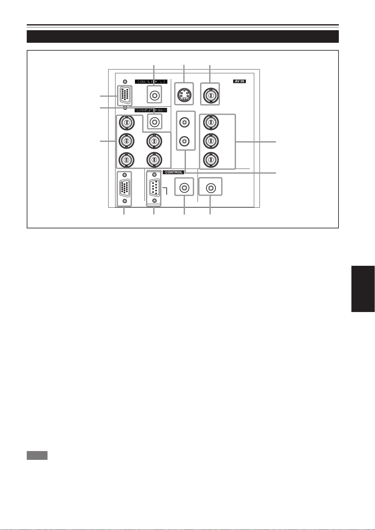
Connector Panel
w
AUDIO
q
PC
p
AUDIO
R
8
G
B
COMPUTER
OUT
7
9
Y/C (S video) input terminal (Mini DIN 4 pin)
1
Connect this terminal to the S video output terminal of a
VCR, etc.
VIDEO (composite video) input terminal (BNC)
2
Connect this terminal to the composite video output terminal
of a VCR, etc.
S
H/C
V
RS-232C
1
Y/C VIDEO
AUDIO
2
Y
L
R
Y
P
/B-Y
B
P
/R-Y
R
3
4
REMOTE
6
AUDIO OUT
5
AUDIO OUT (audio output) terminal (stereo mini jack)
5
Of input signals inputted to the projector, the audio signal
of the device being projected is output. Volume should be
adjusted using the VOL. (+/–) buttons on the remote control
or VOLUME on the setting menu. When a cable is
connected to this jack, no audio sound is produced from
the projector’s speakers.
Y, PB/B-Y, PR/R-Y input terminals (BNC)
3
These are input terminals for component (Y, B-Y, R-Y)
signals or DTV-format (Y, P
B, PR) signals.
Device with component output terminals can be
connected.
* For details about DTV-format signals (480i, 480p, 720p,
1080i) compatible with this unit, refer to page 69.
AUDIO L/R (Audio • left/right) input terminals (pin jacks)
4
Of devices connected to the video input terminals, such
as a VCR, etc., the audio output terminals of the device to
be projected is connected to these terminals. The input
audio signal is reproduced by the speakers of the projector.
The signal is also output from the AUDIO OUT terminal of
the projector.
* When the input signal is stereo signal, connection should
be made to both L and R.
* Signals from a monaural device should be connected to
only L. That way , the projector’s speakers and the AUDIO
OUT terminal produce the same sound from both L and R.
Memo
To select the proper audio input for video input:
The video input terminals (AV IN input terminals) can be switched
with the projector’s or remote control’s VIDEO button. However, since
this projector has only single audio input terminal, reconnect audio
input in accordance with the AV device to be used.
REMOTE terminal (mini jack)
6
Connect an infrared remote control extension unit, etc. to
this jack.
* For details, consult your dealer.
RS-232C terminal (D-sub 9 pin)
7
This is a RS-232C interface-specified terminal. This
projector can be controlled by a computer connected
externally.
* For details, consult your dealer.
COMPUTER OUT (computer output) terminal (D-sub
8
3-row 15 pin)
The computer input signal projected on the screen is output.
A display unit can be used by connecting it to this terminal.
ENGLISH
11
Page 13
Controls and Features (Cont.)
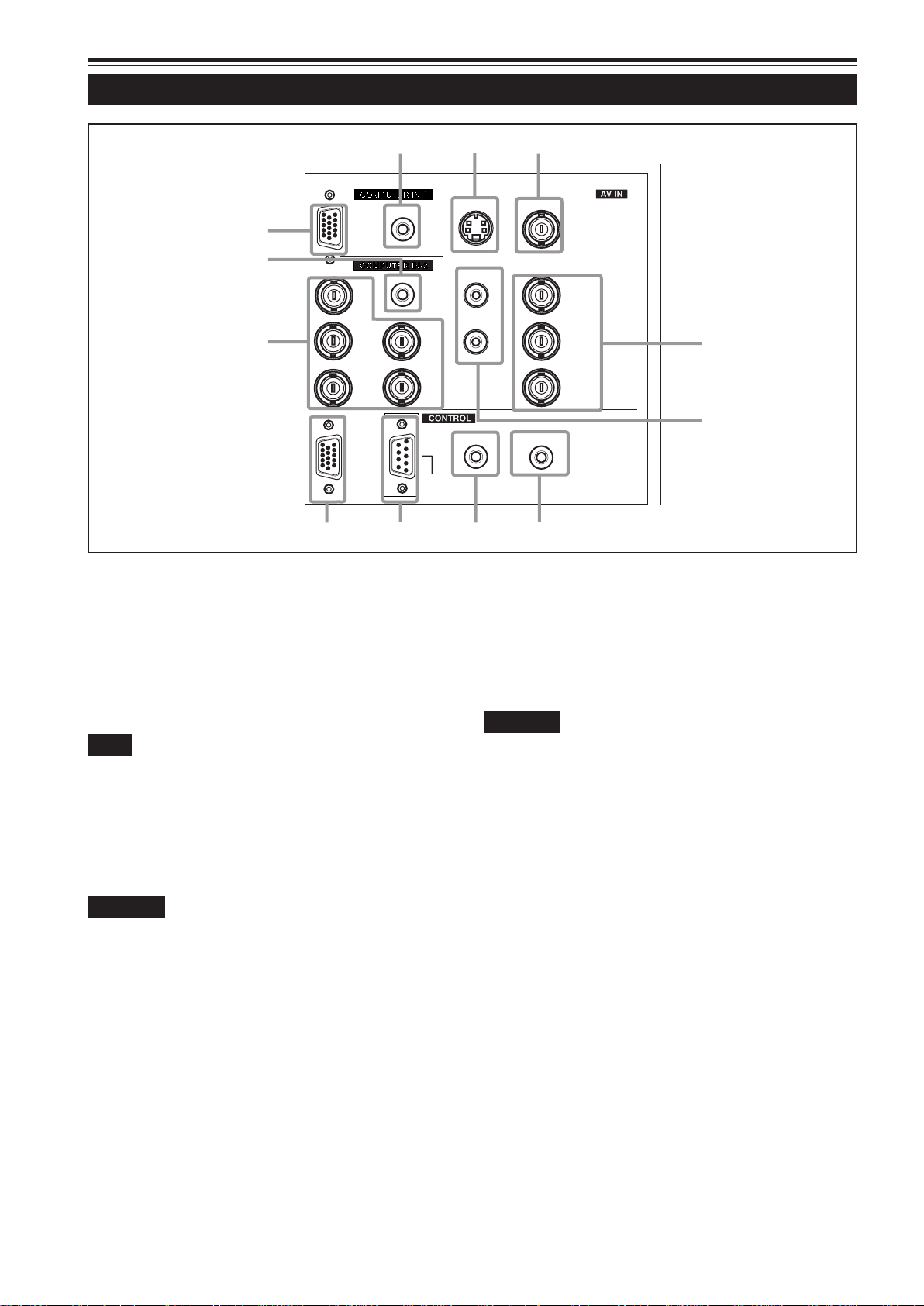
Connector Panel (Cont.)
w
AUDIO
q
PC
p
AUDIO
R
H/C
9
G
B
COMPUTER
OUT
8
COMPUTER IN (computer input) -2 terminal (BNC)
9
These are input terminals for analog RGB signals, vertical
sync (V) signals, and horizontal sync (H) signals /
composite signals (Cs). Devices which have analog RGB
signal output terminals can be connected.
* Input of external sync signals is automatically
detected.
Detection of H/V signals or Cs signals causes automatic
switch to external sync. The priority order is H/V > Cs.
Note
• DTV-format (480i, 480p, 720p, 1080i) signals can be input.
When the source is set to “AUTO”, signals of 480i and 1080i can
automatically be detected, but 480p and 720p signals can not be
detected.
To be able to input 480p or 720p signal, the source should be set
to a dedicated source mode “SDTV(480p)” or “HDTV(720p)”. For
setting the source, refer to “Changing (Setting) the Source” on
page 47.
CAUTION
• When computer-related signals are input, the uppermost
edge of the screen may appear bowing if the sync signal
input is composite sync (Cs) or G on sync signal. In that
case, use separate sync signals for vertical sync (V) and
horizontal sync (H).
AUDIO input terminal (stereo mini jack)
p
This is an audio input terminal for COMPUTER IN
(computer input) -2 terminal. Connect the audio output
signal of a device connected to COMPUTER IN (computer
input) -2 terminal.
* When input to COMPUTER -2 is selected, the audio signal
input is reproduced by the projector’s speakers. Also,
signals can be output from the AUDIO OUT (audio output)
terminal.
(However, if a cable is connected to AUDIO OUT (audio
output) terminal, audio sound does not come out from
the projector’s speakers.)
12
S
V
RS-232C
7
1
Y/C VIDEO
AUDIO
2
Y
L
R
Y
/B-Y
P
B
/R-Y
P
R
3
4
REMOTE
6
AUDIO OUT
5
COMPUTER IN (computer input) -1 terminal (D-sub 3-
q
row 15 pin)
This is an input terminal (PC) dedicated for computer
signals (RGB video signals and sync signals).
Connect the display output terminal of the computer to this
terminal. When a Macintosh computer is to be connected,
use the Conversion adapter for Mac supplied.
CAUTION
• When computer-related signals are input, the uppermost
edge of the screen may appear bowing if the sync signal
input is composite sync (Cs) or G on sync signal. In that
case, use separate sync signals for vertical sync (V) and
horizontal sync (H).
AUDIO (audio) input terminal (stereo mini jack)
w
This is an audio input terminal for COMPUTER IN
(computer input) -1 terminal. Connect the audio output
signal of a device connected to COMPUTER IN (computer
input) -1 terminal.
* When input to COMPUTER -1 is selected, the audio signal
input is reproduced by the projector’s speakers. Also,
signals can be output from the AUDIO OUT (audio output)
terminal.
(However, if a cable is connected to AUDIO OUT (audio
output) terminal, audio sound does not come out from
the projector’s speakers.)
Page 14
Controls and Features (Cont.)
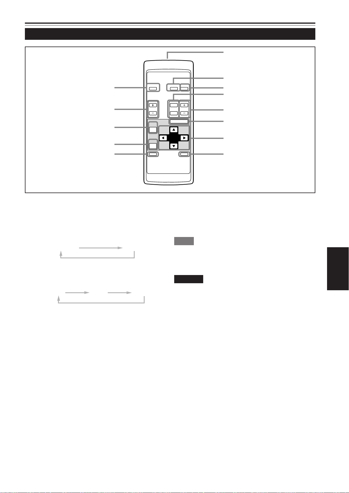
Remote Control Unit
e
w
q
OPERATE
VOL.
PAGE
BACK
COMPUTER VIDEO
T
ZOOM FOCUS
W
MENU/ENTER
1
2
3
4
5
6
p
9
Remote control’s signal transmitter
1
COMPUTER button
2
Use this button to select the devices connected to the
projector’s COMPUTER IN (computer input) -1 and -2 input
terminals. Each time you press the button, the selection
changes as follows:
COMP 1
VIDEO button
3
Use this button to select the devices such as a video
connected to the projector’s A V IN (A V input) terminal. Each
time you press the button, the selection changes as follows:
Y/C
ZOOM (T/W) buttons
4
VIDEO
Use these buttons to adjust the screen size. (The projection
lens used in this projector is a long focal-distance zoom
lens (1.9 x zoom lens for 2.9:1 to 5.5:1) with manual shift
function.)
T:The screen size decreases.
W:The screen size increases.
FOCUS (+/–) buttons
5
Use these buttons to adjust the focus of the projected video.
+: The focus point becomes more distant.
–: The focus point becomes nearer.
MENU/ENTER button
6
Use this button to display the main menu. While the main
menu is displayed, pressing this button displays a details
setting (submenu) for items with details settings.
Cursor (5/∞/2/3) buttons
7
While the main menu is displayed, use these buttons to
select an item to adjust or make adjustment.
AV MUTING (On/Off) button
8
Use this button to turn off the video image and audio sound
temporarily . Pressing it again makes the video image and
audio sound to resume.
COMP 2
YPBPR
PRESET
QUICK
ALIGN.
7
AV
MUTING
QUICK ALIGN. (Quick Alignment) button
9
Use this button to automatically adjust TRACKING,
PHASE, H. POS. and V. POS. of the projected video.
During the automatic adjustment, QUICK-ALIGNMENT
appears on the screen, and disappears after it is finished.
Memo
Quick alignment function:
Does not work for video input (AV IN input terminal) signals.
Works only for computer-related (COMPUTER-1 and-2 input terminals)
signals.
CAUTION
• Automatic adjustment with the quick alignment function should be
done on a bright still-picture screen. This function may not work
correctly on a dark screen or motion-picture screen. If adjustment
with this function is not satisfactory, adjust TRACKING, PHASE, H.
POS. and V. POS. manually (see pages 32, 38 and 39).
PRESET button
p
While making adjustment on the main or setting menu,
use this button to reset the setting of the selected item to
the factory-set value. This button works only for numerical
settings and does not work for switching ON to OFF.
PAGE BACK button
q
While a details setting is displayed, use this button to go
back to the previous page.
VOL. (Volume) (+/–) buttons
w
Use these buttons to adjust the sound volume:
+: Increase the volume level.
–: Decrease the volume level.
OPERATE button
e
To turn on the power, press this button for one second or
more.
* About 30 seconds after the power has turned on, video
image will appear on the screen.
8
13
ENGLISH
Page 15
Controls and Features (Cont.)
Installing Batteries
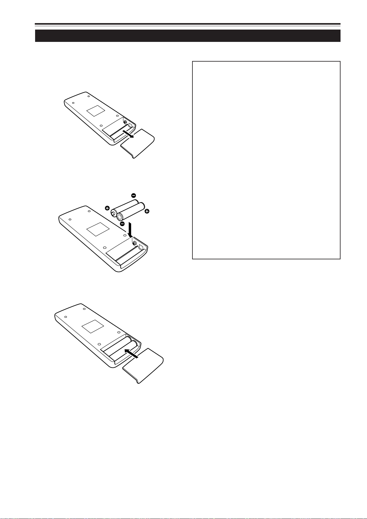
Install batteries in the remote control. If the remote control has started to work erratically, replace the batteries.
Open the back cover.
1
While pushing on the back cover, slide it in the direction
of the arrow.
Install the batteries.
2
Place the two batteries (AAA/R03-size) supplied in the
remote control as illustrated below.
Precautions for using batteries
If batteries are used incorrectly, they may crack or
leak liquid. This could cause a fire, burn, malfunction,
or staining or damaging the surrounding.
Beware of the following:
• Do not mix new and old batteries.
• Do not mix different types of batteries as they differ in
characteristics.
• Place batteries so they match the polarities indicated:
(+) to (+) and (–) to (–).
• Be sure to put the minus (–) end in first to avoid shortcircuiting.
• Use only designated batteries.
• Remove the batteries if not used for a prolonged period
of time.
• When the batteries are exhausted, replace them
immediately . Otherwise, liquid could leak, or malfunction
could occur due to leaked liquids. If the leaked liquid
contacts the skin, wipe it off with a cloth, otherwise the
skin could become rough.
• Do not put batteries into fire or try to recharge them.
• Batteries run for six months to one year in normal use.
But the batteries supplied are for confirming operation
and may not run that long. When the remote control starts
failing to work properly, replace the batteries with new
ones.
Close the back cover.
3
Slide the back cover in the direction of the arrow until a
click is heard.
14
Page 16
Installing the Projector
Precautions for Installation
CAUTION
Do not install the projector in the following places:
• There is much water, humidity or dust.
• The projector may be subjected to oil smoke or cigarette smoke.
• On a soft surface such as a carpet or cushion.
• The projector may be subjected to direct sunlight.
• Temperature is high or humidity is low.
Allowable operation temperature range: + 5°C to + 35°C (41°F to 95°F)
Allowable relative humidity range: 20% to 80% (no condensation)
Allowable storage temperature range: –10°C to +60°C (14°F to 140°F)
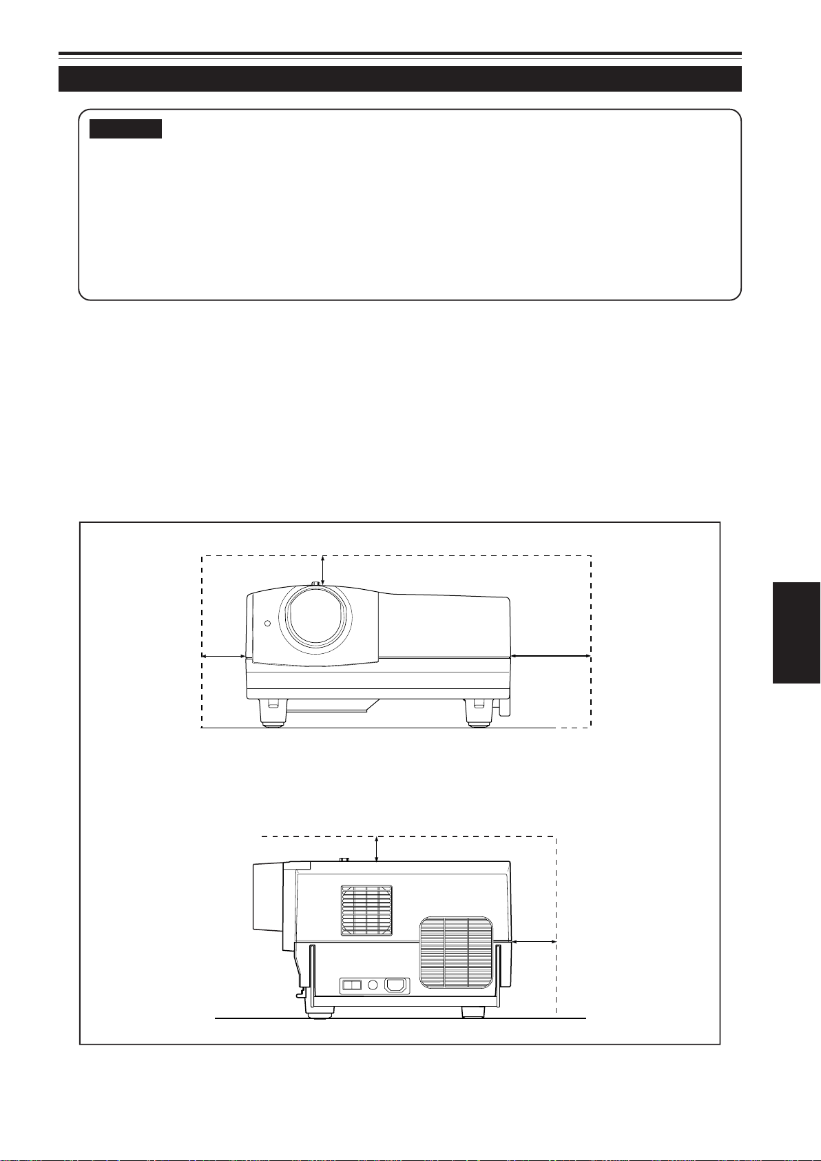
■ When installing the projector, observe the followings:
• Do not use the projector placed on its side.
Avoid using the projector placed on its side. This could cause a malfunction.
• Use the projector within the installed angle.
Avoid using the projector inclined ±30° or more right-to-left or left-to-right. This could cause color variation or harm the lamp
life.
• Do not block the exhaust vents.
Do not use a cover which encloses the projector air-tight or blocks the exhaust vents. Allow sufficient space around the
projector. When the projector is enclosed in a space of the following dimensions, use an air conditioner so the temperature
inside becomes equal to the outside temperature.
Allowable minimum space required
20cm (7 - 7/8”) 60cm (23 - 5/8”)
30cm (11 - 13/16”)
ENGLISH
30cm (11 - 13/16”)
20cm (7 - 7/8”)
15
Page 17
Installing the Projector (Cont.)
Projection Distance and Screen Size
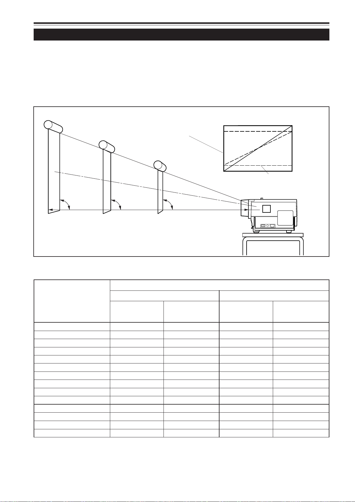
● The projection lens used in this projector is a long focal-distance zoom lens (1.9 x zoom lens f or 2.9:1 to 5.5:1) with
manual shift function.
● The range of projection distances that can be focused is approx. 14.83 ft (approx. 4.52 m) to approx. 98 ft (approx.
29.87 m) when the aspect ratio of the screen is 4:3. Set this projector within this range. Refer to “Relationship
between Projection Distances and Projection Screen Sizes” (on pages 16 and 71).
● With this projector, the pr ojection screen can be shifted up and do wn in position within the range of appro x. 30% to
55%. The amount of shift shown in the illustration is 50% shifting. See page 17 for “Setting the Amount of Lens
Shifting”.
Screen
■ Change of projection screen
according to aspect ratio
Screen with 4 : 3 aspect ratio
Screen with 16 : 9 aspect ratio
90°
90° 90°
Center line of the lens
When the amount of shift is
selected to be 50%, set the screen
so that its bottom edge is the
same height as the center line of
the lens.
■Relationship between Projection Distances and Projection Screen Sizes
Projection screen size Approximate projection distance
(Diagonal length) For 4:3 aspect-ratio screens For 16:9 aspect-ratio screens
Wide end Tele end Wide end Tele end
unit: inch (cm) unit: ft (m) unit: ft (m) unit: ft (m) unit: ft (m)
40 (approx. 101.6) --------- --------- 14.83 ( 4.52) --------- --------- 16.11 ( 4.91)
60 (approx. 152.4) --------- --------- 22.05 ( 6.72) --------- --------- 23.98 ( 7.31)
70 (approx. 177.8) --------- --------- 25.66 ( 7.82) 14.83 ( 4.52) 27.92 ( 8.51)
80 (approx. 203.2) 15.55 ( 4.74) 29.30 ( 8.93) 16.93 ( 5.16) 31.86 ( 9.71)
100 (approx. 254.0) 19.36 ( 5.90) 36.52 (11.13) 21.06 ( 6.42) 39.76 (12.12)
150 (approx. 381.0) 28.87 ( 8.80) 54.59 (16.64) 31.43 ( 9.58) 59.45 (18.12)
200 (approx. 508.0) 38.39 (11.70) 72.67 (22.15) 41.77 (12.73) 79.17 (24.13)
240 (approx. 609.6) 45.97 (14.01) 87.14 (26.56) 50.07 (15.26) 94.92 (28.93)
250 (approx. 635.0) 47.87 (14.59) 90.78 (27.67) 52.13 (15.89) --------- --------270 (approx. 685.8) 51.67 (15.75) 98.00 (29.87) 56.27 (17.15) --------- --------280 (approx. 711.2) 53.58 (16.33) --------- --------- 58.33 (17.78) --------- --------350 (approx. 889.0) 66.90 (20.39) --------- --------- 72.84 (22.20) --------- --------470 (approx. 1193.8) 89.70 (27.34) --------- --------- 97.71 (29.78) --------- --------510 (approx. 1295.4) 97.31 (29.66) --------- --------- --------- --------- --------- ---------
*This list is extracted from “Relationship between Projection Distances and Projection Screen Size” on page 71. The projection
screen sizes and projection distances are only for a guide. Use them as reference when setting the projector.
16
Page 18
Installing the Projector (Cont.)
CAUTIONS and NOTES
• When installing a screen, use a 4:3 aspect-ratio picture.
(A 16:9 aspect-ratio picture is projected based on the width of the range in which a 4:3 aspect-ratio picture is projected.)
• The diagonal length of a 16:9 aspect-ratio screen is about 91.8% that of a 4:3 aspect-ratio screen. This value is only a
guide (reference).
• If sunlight or lamp light strikes the projection screen directly, the picture tends to become whitish and dim. Be sure to use
a curtain, etc. to shield the light.
• Trapezoidal distortion may not be corrected. Set the projector horizontally on a surface that is within the range of adjustable
angles (up/down adjustment angle: +7° ; horizontal adjustment angle: ±1.5°).
• The values listed in table “Relationship between Projection Distances and Projection Screen Sizes” are provided only as
a guide (reference). The projected screen size may vary depending on the manufacturing tolerance of the projection lens.
• When hanging from the ceiling, use a dedicated hanging fixture.
Setting the Amount of Lens Shifting
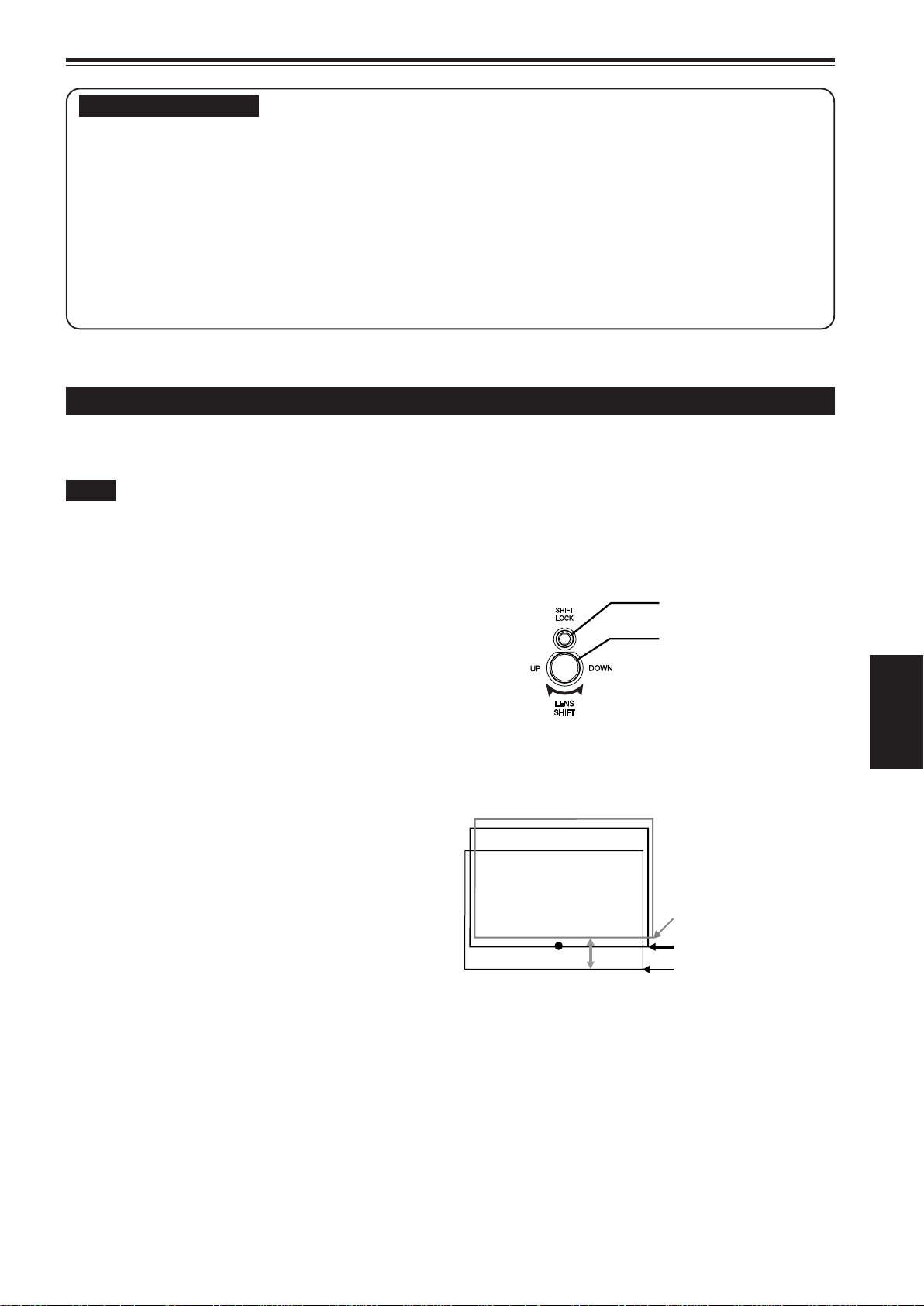
This projector features a lens shifting function which allows you to shift the projection screen up and down in position.
Depending on installation conditions, you may need to use this function to make adjustments.
Notes
• The amount of shifting is within the range of approx. 30% to 55%. The factory setting is 30%.
• After finishing the lens shift setting (adjustment), tighten the SHIFT LOCK fixing bolt firmly so the lens will not move.
Loosen the SHIFT LOCK fixing
1
bolt.
Use the hex wrench supplied.
Rotate the LENS SHIFT knob to ad-
2
just the position (shift amount) of
the projection screen.
Rotate it to the right: The lens shifts upward.
Rotate it to the left: The lens shifts downward.
Tighten the SHIFT LOCK fixing
3
bolt firmly.
Use the hex wrench supplied.
SHIFT LOCK fixing bolt
LENS SHIFT knob
ENGLISH
■ Projected screen position image by amount of shift
* The projection position can
only shift in an up-and-down
direction.
The illustration shows the
screen shifted sidewise for
the purpose of explanation.
Approx. 55%
Approx. 50%
Approx. 30% (factory setting)
17
Page 19
Installing the Projector (Cont.)
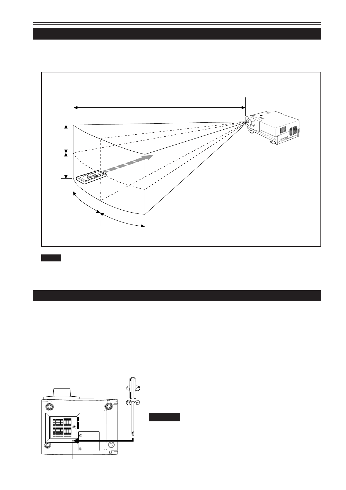
Effective Range and Distance of the Remote Control Unit
The operable distance of the remote control unit (A) is approx. 32.81 ft (approx. 10 m) and the operable angles of the remote
control unit is 50° right to left, and 15° up and down.
The effective range and distance of the remote control unit
A
Y
C
N
P
E
G
M
E
R
T
E
P
M
M
E
A
L
E
T
A
R
E
P
O
Y
B
D
N
A
T
S
15˚
Projector
DLA-L20U
15˚
Remote control unit
50˚
50˚
Notes
• Operate the remote control unit aiming signal transmitter of the remote control directly at the remote sensor on the projector. The remote
control may not work correctly if there is a shielding object between the remote control and the remote sensor.
• When the effective distance or operation of the remote control becomes unstable, replace the batteries with new ones.
Setting the Position Selecting Screw for Ceiling Mounting
When using the projector in an upside-down, ceiling-mounted position (inverted top-to-bottom and right-to-left), the “position
selecting screw for ceiling mounting” must be turned to switch to ceiling mounting.
This will correct variance in color images (shading), which otherwise would occur in ceiling mounting.
To revert to normal desktop setting, turn the “position selecting screw for ceiling mounting” back to the initial position (factoryshipped).
[When using the projector in an upside-down, ceiling mounting position (inverted top-to-bottom and right-to-left)]
■ Turn the “position selecting screw for ceiling mounting” counterclockwise fully (until it is turning idly).
[To again use the projector in a normal desktop setting]
■ Turn the “position selecting screw for ceiling mounting” clockwise fully (until it tightens firmly).
For normal desktop mounting:
Turn clockwise.
For upside-down, ceiling-mounting:
Turn counterclockwise.
CAUTIONS
• To ceiling-mount and adjust the projector, special expertise and technique
are necessary. Be sure to ask your dealer or a specialist to perform this
work.
• To turn the “position selecting screw for ceiling mounting”, use a Phillips
screwdriver with a 30-mm or longer shank.
Position selecting screw for ceiling mounting
The screw is located in the hole shown in the illustration.
18
Page 20
Connecting to Various Devices
* Before connection, be sure to turn off the projector and connected devices.
* Read the manual which comes with each device thoroughly.
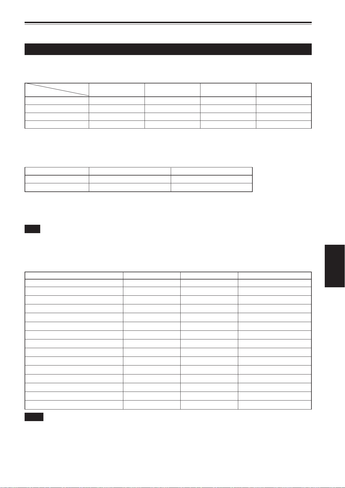
Signals that Can Be Input to the Projector
The following signals can be input to the projector:
■ Video signals
(1) Response to color systems
Color system
Input terminal
VIDEO ‡‡‡‡
Y/C ‡‡*
Y, PB/B-Y, PR/R-Y ‡*
G, B, R, H/Cs, V ‡*
*
: Responds if Y/C output is available.
1
*
: Signifies that component signals (“Y, PB, PR ” / “ Y, B-Y, R-Y” / “G, B, R, H/CS, V”) conform to the signal timing (synchroniza-
2
NTSC NTSC4.43 PAL SECAM
1
2
2
‡*
‡*
2
2
‡ - - - - ‡*
‡*
2
2
‡*
‡*
2
2
tion and video period) of each color system. The color systems are used for convenience only.
(2) Response to double density (*1), high-vision signals
Input terminal NTSC*
Y, PB/B-Y, PR/R-Y ‡‡
G, B, R, H/Cs, V ‡‡
2
High-vision signal
*1 : Signals whose density of scanning lines/field is twice as high.
*
: Responds to signals whose horizontal scanning frequency is 31.5 kHz. NTSC can be made twice as dense by a line doubler
2
(separately available: recommended article). Also, possible to respond to fully-specified, decoded 525P progressive signals.
Note
• DTV-format signals (480i, 480p, 720p, 1080i) can be input into this unit (Y, PB/B-Y, PR/R-Y input terminals). For details about DTV-format
signals (480i, 480p, 720p, 1080i) compatible with this unit, refer to page 69.
■ Computer signals
• Signals with the following resolutions can be input to the input terminal of COMPUTER IN-1 (PC) or COMPUTER IN-2 (G,
B, R, H/Cs, V). (The following signals are preset.)
Screen resolution (standard name) Horizontal frequency Vertical frequency Scanning method
640 × 400 (PC-9801) 24.8 kHz 56.4 Hz Non-interlace
640 × 350 (VGA1) 31.5 kHz 70.1 Hz Non-interlace
640 × 480 (VGA3) 31.5 kHz 59.9 Hz Non-interlace
640 × 480 (Macintosh 13”) 35.0 kHz 66.7 Hz Non-interlace
640 × 480 (VGA VESA) 37.5 kHz 75.0 Hz Non-interlace
800 × 600 (SVGA1) 37.9 kHz 60.3 Hz Non-interlace
800 × 600 (SVGA2) 48.1 kHz 72.2 Hz Non-interlace
832 × 624 (Macintosh 16”) 49.7 kHz 74.6 Hz Non-interlace
1024 × 768 (XGA1) 48.4 kHz 60.0 Hz Non-interlace
1024 × 768 (XGA2) 56.5 kHz 70.1 Hz Non-interlace
1024 × 768 (Macintosh 19”) 60.2 kHz 74.9 Hz Non-interlace
1152 × 870 (Macintosh 21”) 68.7 kHz 75.0 Hz Non-interlace
1280 × 1024 (SXGA1) 64.0 kHz 60.0 Hz Non-interlace
1280 × 1024 (SXGA2) 70.8 kHz 67.0 Hz Non-interlace
1360 × 1024 (SXGA3: Mac Board) 80.0 kHz 75.1 Hz Non-interlace
ENGLISH
Notes
• Interlace signals are not handled.
• Some signals other than listed above can be displayed. But they require adjustment. Even some of the signals listed above may require
adjustment depending on the video board used.
• When a signal other than listed above is input, the screen could be partially erased or an unneeded fold-over screen could appear.
• Even signals in the frequency range that can be input may not be displayed normally depending on the type of the signal.
• Composite sync.(Cs) and G on sync. signals can not handled depending on the devices connected.
19
Page 21
Connecting to Various Devices (Cont.)
Connecting to Video Devices
Before connection, be sure to turn off both the projector and video device.
• Read the manual which comes with each video device thoroughly.
• Use the supplied AV connection cable. An AV connection cable with an S video terminal is not supplied.
To Y/C
(separately available)
BNC-RCA conversion plug (supplied)
S video cable
To VIDEO
T o AUDIO (L)
T o AUDIO (R)
AV connection
cable (supplied)
V
Y/C VIDEO
AUDIO
L
R
REMOTE
AUDIO OUT
Y
Y
P
/B-Y
B
P
/R-Y
R
To select the proper audio input for video input
The video input terminal (AV IN input terminal) can
be switched with the VIDEO button. However, since
this projector has only a single audio input terminal,
reconnect audio input in accordance with the AV
device to be used.
Connecting to Hi-Vision Devices
Video devices
• VCR (Video Cassette recorder)
• Laser video disc player
• Camcorder
Memo
• When connecting a video device, use a TBC along with it, or one
which has a built-in TBC.
• Use of an extension cable to connect a video device and the
projector could cause video degradation.
• When a signal with much jitter is reproduced on a VCR or specialeffect playback is performed, the upper part of the picture or the
picture itself may be erased or distorted.
Before connection, be sure to turn off both the projector and Hi-Vision devices.
• Read the manual which comes with each Hi-Vision device thoroughly.
• Use separately available BNC cables and audio cables to connect Hi-Vision devices.
T o AUDIO (R)
T o AUDIO (L)
Audio cable
(separately available)
To VIDEO
To Y
To PB/B-Y
To PR/R-Y
BNC cable (separately available)
V
RS-232C
Y/C VIDEO
AUDIO
L
R
REMOTE
AUDIO OUT
Y
Y
P
/B-Y
B
P
/R-Y
R
To select the proper audio input for video input
The video input terminal (AV IN input terminal) can
be switched with the VIDEO button. However, since
this projector has only a single audio input terminal,
reconnect audio input in accordance with the AV
device to be used.
Hi-Vision devices
• W-VHS VCR
• Text/video camera
• Hi-Vision video camera
Memo
• Other devices with component signal output terminals (DVD player
(NTSC), etc.) can be connected. (*DVD: Digital Video Disc)
• DTV-format signals (480i, 480p, 720p, 1080i) can be input. For
DTV-format signals that can be handled, refer to page 69.
20
Page 22
Connecting to Various Devices (Cont.)
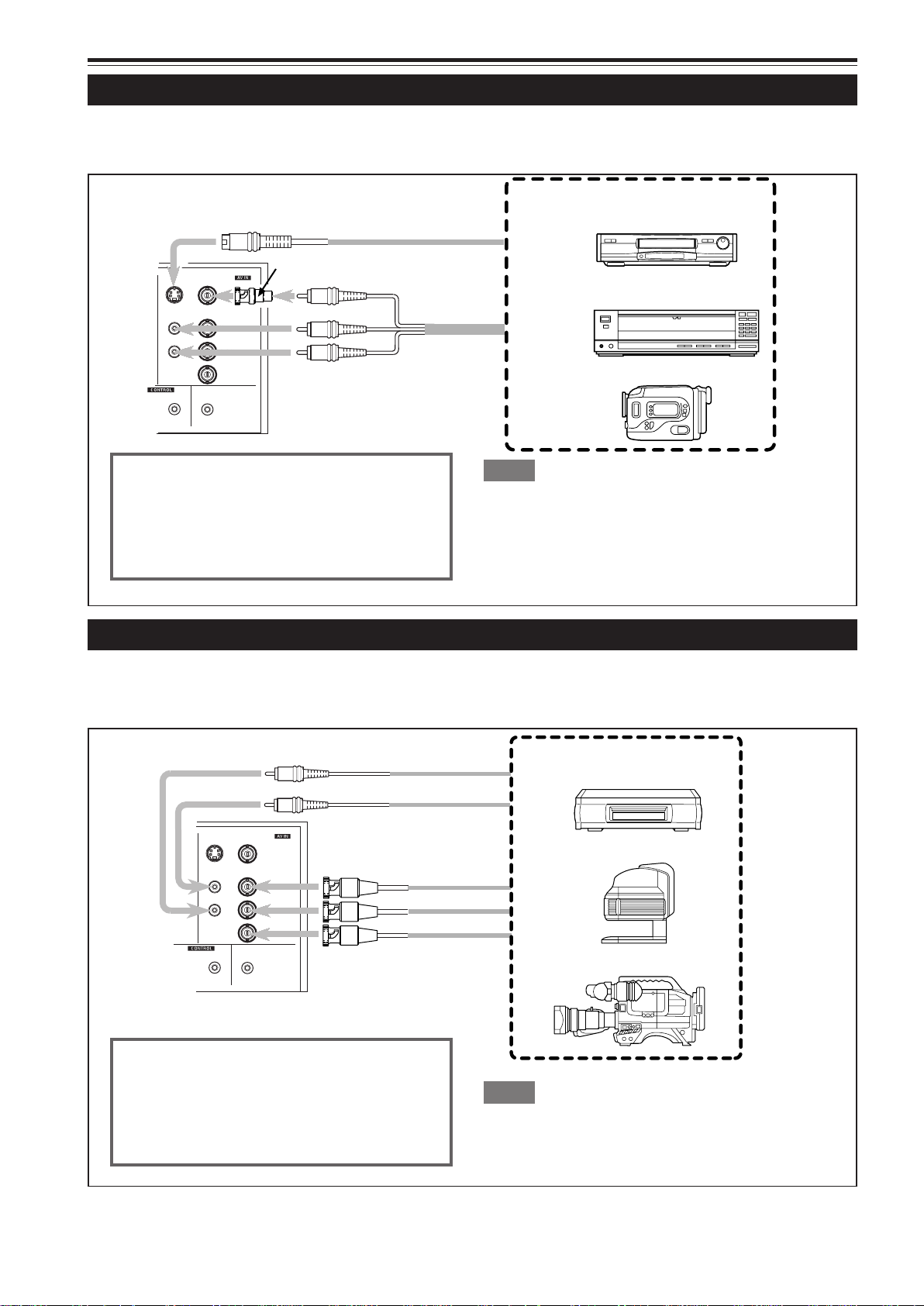
Connecting to Other Devices
Before connection, be sure to turn off both the projector and other devices to be connected.
• Read the manual thoroughly which comes with the device to be connected.
• Speakers with a built-in amplifier and game devices can be connected. Use the A V connection cable and audio cable supplied,
or the cable supplied with a game device.
RS-232C
Y/C VIDEO
AUDIO
L
R
REMOTE
BNC-RCA conversion plug (supplied)
To VIDEO
T o AUDIO (L)
Y
Y
/B-Y
P
B
T o AUDIO (R)
Cable supplied with the game
device, or supplied AV connection
AUDIO OUT
P
/R-Y
R
cable
T o AUDIO OUT
• Speakers with a built-in amplifier
• Game device, etc.
Audio cable (supplied)
(or stereo mini-plug)
Connecting to Devices which Control the Projector
Before connection, be sure to turn off both the projector and devices to be connected.
• Read the manual thoroughly which comes with each device to be connected.
• By connecting a computer to the RS-232C terminal, you can control the projector. Also, you can make an infrared remote
sensor extension unit and connect it to the REMOTE terminal of the projector.
* Obtain connection cables as required.
* For details, consult your authorized dealer or service center.
• Desktop type
H/C
S
V
RS-232C
Y/C
AUDIO
L
R
REMOTE
• Note type
To RS-232C terminal
To RS-232C terminal
RS-232C reverse connection
cable (separately available)
To RS-232C connector
Infrared remote
sensor extension unit
(Needs to be made)
AUDIO
PC
AUDIO
R
G
B
COMPUTER
OUT
To REMOTE terminal
ENGLISH
21
Page 23
Connecting to Various Devices (Cont.)
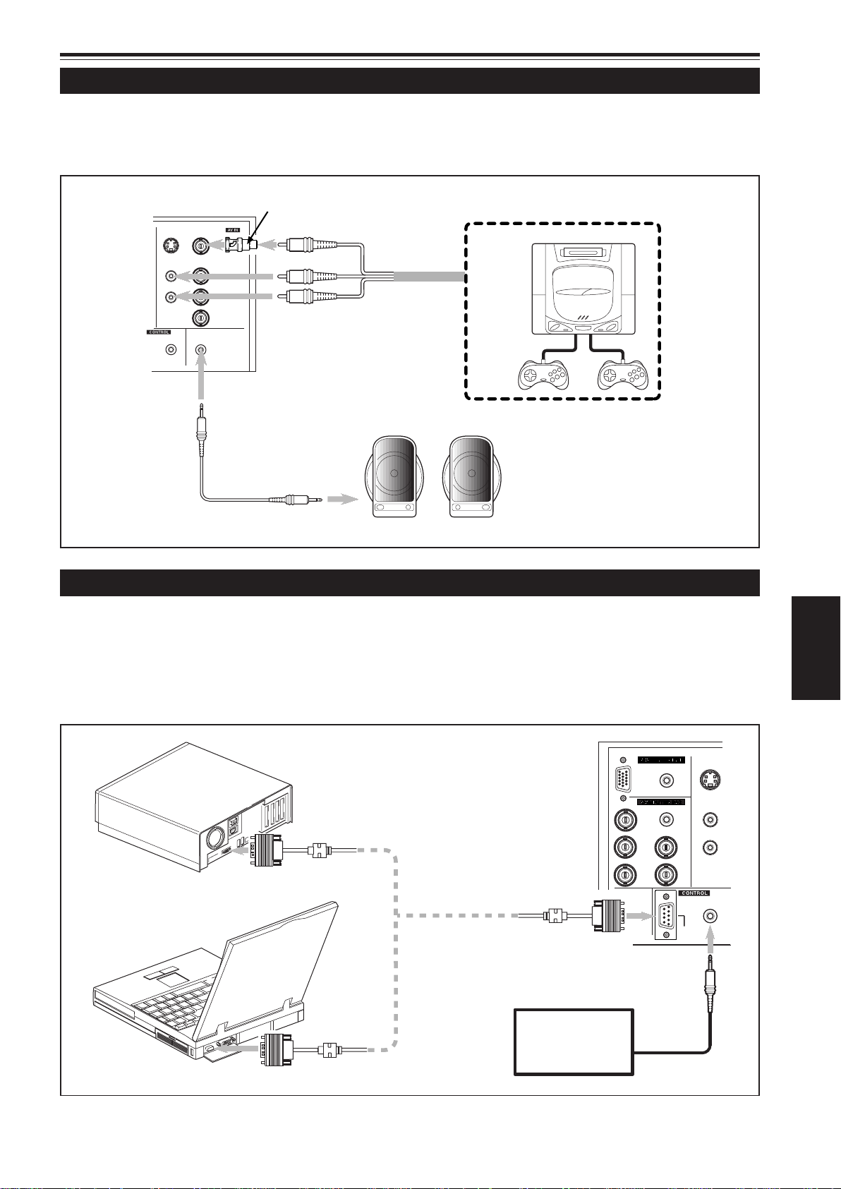
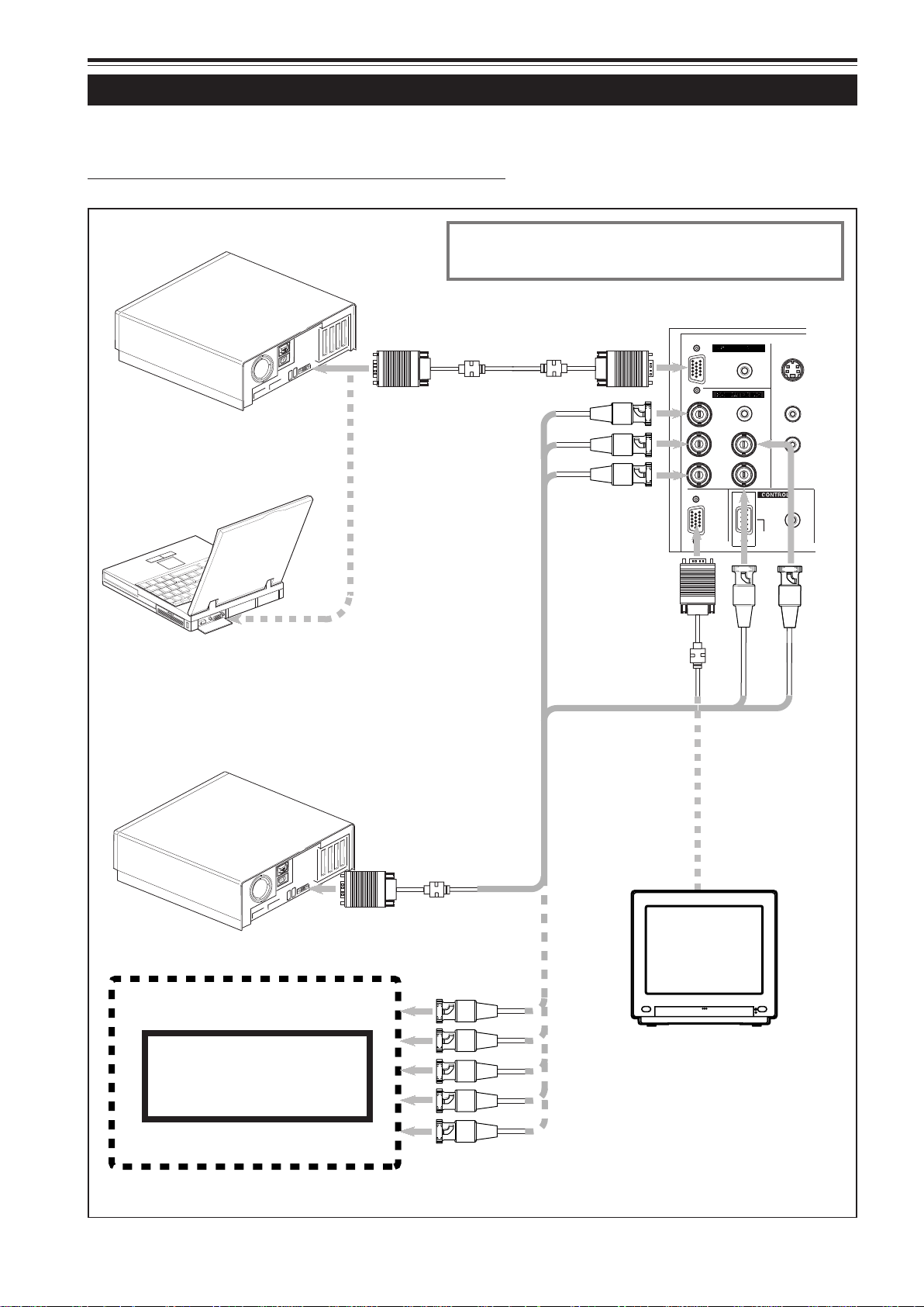
Connecting to Computer Devices
Before connection, be sure to turn off both the projector and computer devices.
• Read the manual which comes with each device thoroughly.
■ Connection to an IBM PC or IBM-compatible computer
• Use the supplied computer connection cable. Also, prepare cables required for connecting the devices connected.
• Desktop type
Personal Computer
connection cable (supplied)
To monitor connector
• Note type
* There are some note types which do not allow the computer ’s
LCD to work if an external display is connected. With such a note
type, the LCD display and external display output need to be
switched.
When connecting an audio output terminal such as a computer sound
source to the projector, connect to the AUDIO terminal using the supplied
audio cable.
To COMPUTER IN-1
Y/C
AUDIO
L
To R
AUDIO
PC
AUDIO
R
To G
H/C
G
R
S
To B
V
B
COMPUTER
To COMPUTER IN-2
OUT
To COMPUTER OUT
REMOTE
RS-232C
To V
To H/Cs
• Desktop type
• RGB output devices
Laser video disc player, etc.
To monitor connector
Separate cable
(separately available)
To R
To G
To B
To H/Cs
To V
Cable supplied with the
display (or separately
available)(D-sub 3-row
15-pin)
POWER
Display monitor
* When a monitor is connected to the
COMPUTER OUT terminal, you can view
the video from the computer on the
monitor.
22
Page 24
Connecting to Various Devices (Cont.)
Connecting to Computer Devices (Cont.)
Before connection, be sure to turn off both the projector and computer devices.
• Read the manual which comes with each device thoroughly.
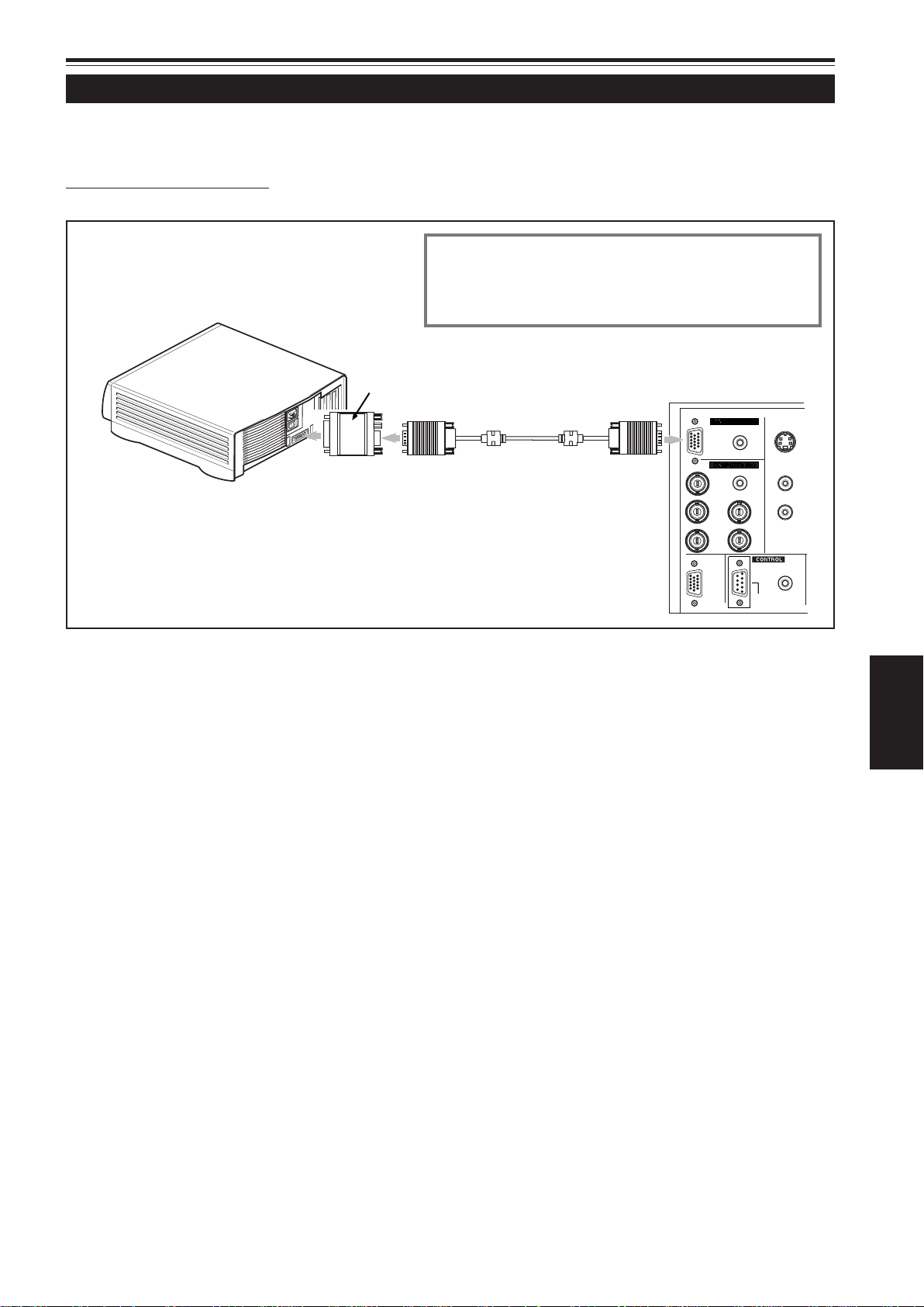
■ Connection to Macintosh
• Use the supplied Personal computer connection cable and the supplied conversion adapter for Mac.
• When connecting an audio output terminal such as a computer sound
source to the projector, connect to the AUDIO terminal using the
supplied audio cable.
• Desktop type
• Other connections are the same as in the connection example for
IBM PC or IBM compatible PCs.
To monitor connector
Conversion adapter for Mac
(supplied)
Personal computer connection cable
(supplied)
To COMPUTER IN-1
PC
R
G
B
COMPUTER
OUT
AUDIO
AUDIO
H/C
S
V
RS-232C
Y/C
AUDIO
L
R
REMOTE
ENGLISH
23
Page 25
Connecting to Various Devices (Cont.)
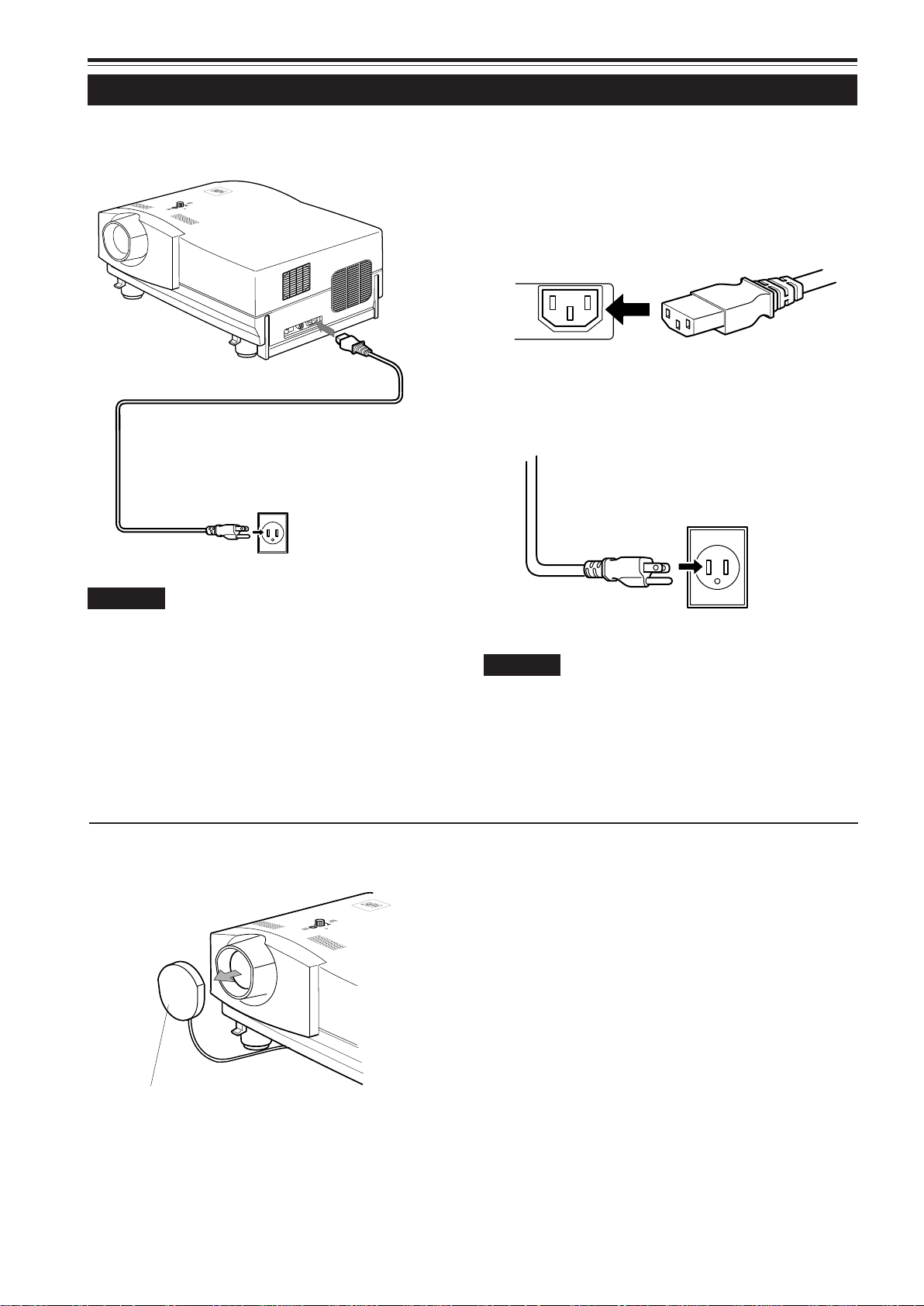
Connecting the Power Cord (Supplied)
After all devices have finished being connected, connect the projector’s power cord. At this time, do not turn on the MAIN
POWER switch yet.
Y
C
N
P
E
G
M
E
R
T
E
P
M
M
E
A
L
E
T
A
R
E
P
O
Y
B
D
N
A
T
S
1
Power cord (supplied)
2
CAUTION
T o pre vent fire and electric shoc k, observe the following:
• When you do not use devices, pull out their power cords
from wall outlets.
• Do not connect the devices with power cords other than
supplied.
• Do not use voltage other than the power voltage indicated.
• Do not scar, damage, or work on the power cords. Also, do
not put a heavy object on, heat or pull the power cords,
otherwise they may be damaged.
• Do not insert or pull out the plugs with a wet hand.
1 Insert the supplied power cord
into the power input terminal (AC
IN
~) of the projector.
AC IN ~
2 Insert the plug of the supplied
power cord into a wall outlet.
CAUTION
• Since the power requirement of the projector is high, be sure
to insert the power plug directly into a wall outlet.
24
Lens cap
■To use the projector
• Remove the lens cap.
Y
C
N
P
E
G
M
E
R
T
E
P
M
M
E
A
L
E
T
A
R
E
P
O
Y
B
D
N
A
T
S
* The lens cap has a string attached and it is fixed to the
projector.
Be sure to fit lens cap when not in use.
Page 26
Connecting to Various Devices (Cont.)
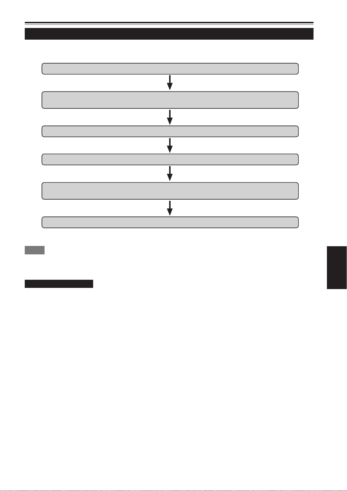
When Turning On the Devices Connected to the Projector
Turn on the switches of the projector and the devices connected in the following order.
Skip over unconnected devices if there is any.
Power switch of the monitor of the computer which provides input to the projector
Peripheral devices of the computer which provides input to the projector
(Hard disk, magneto optical disk, scanner, etc.)
Power switch of AV devices which provide input to the projector
Projector itself
Power switches of devices to which the projector provides output
(AV devices and display monitor)
Power switch of the computer which provides input to the projector
* When turning off the power switches, do so in the reverse order.
Memo
When the OPERATE button is pressed but the power is not supplied:
•If the filter or lamp replacement opening cover is displaced, the power is not supplied. Check them for correct installation.
•You must press the OPERATE button for one second or more.
CAUTIONS and NOTES
Do not turn off the MAIN POWER switch suddenly while the projector is being used or immediately after it has been
used. This could cause a malfunction.
•Since the projector uses a high-intensity lamp and is heated to high temperature, cooling fans are operating even during
projection. So, after use, the cooling fans continue to run from when the OPERATE button is pressed until the light-source
lamp is cooled down. During cooling, the STAND BY indicator blinks to alert the cooling fans are running. During this time, do
not turn off the main power switch. After the cooling of the light-source lamp is finished (the fans stop) and the STAND BY
indicator comes on, then turn off the main power switch.
•If you press the OPERATE button immediately after the light-source lamp lights, it takes about 40 seconds for the lamp to go
off. To turn the lamp on again, wait 10 seconds or more before pressing the OPERATE button.
ENGLISH
When the TEMP indicator lights, the power turns off automatically.
•While the light-source lamp is on, if an abnormal temperature rise is detected, the TEMP indicator comes on, the power is
automatically cut off, and the projector’s EMERGENCY indicator blinks (goes into an emergency mode).
When the EMERGENCY indicator blinks, turn off the main power switch after the fans have stopped running.
•If the following abnormality occur to the projector, it goes into an emergency mode (the EMERGENCY indicator blinks).
When the projector goes into an emergency mode, it stops projecting automatically and runs the fans for about 20 seconds.
– When the filter is dislodged.
– When the filter is clogged.
– When the light-source lamp suddenly goes off.
– When the fans stop running.
– When the temperature inside rises abnormally high.
– When the AC power supply is suddenly cut or interrupted.
•When the projector goes into an emergency mode:
After the fans have stopped, turn off the MAIN POWER switch and pull out the power cord. After that, re-insert the power cord
and try to operate the projector. If it goes into emergency again, after the fans have stopped, turn off the main power switch,
pull out the power cord, and consult your authorized dealer or service center for repair.
25
Page 27
Basic Operations
■ Projector’s buttons
STAND BY
LAMP
TEMP
EMERGENCY
VIDEO
COMPUTER
SETTING
3
+
QUICK
ALIGN.
2
-
Y
C
N
E
P
G
M
R
E
T
E
P
M
M
E
A
L
E
T
A
R
E
P
O
Y
B
D
N
A
T
S
STAND BY indicator
OPERATE indicator
OPERATE button
2, 1
MAIN POWER switch
1, 2
The following describes the basic procedure for normal use of
the projector.
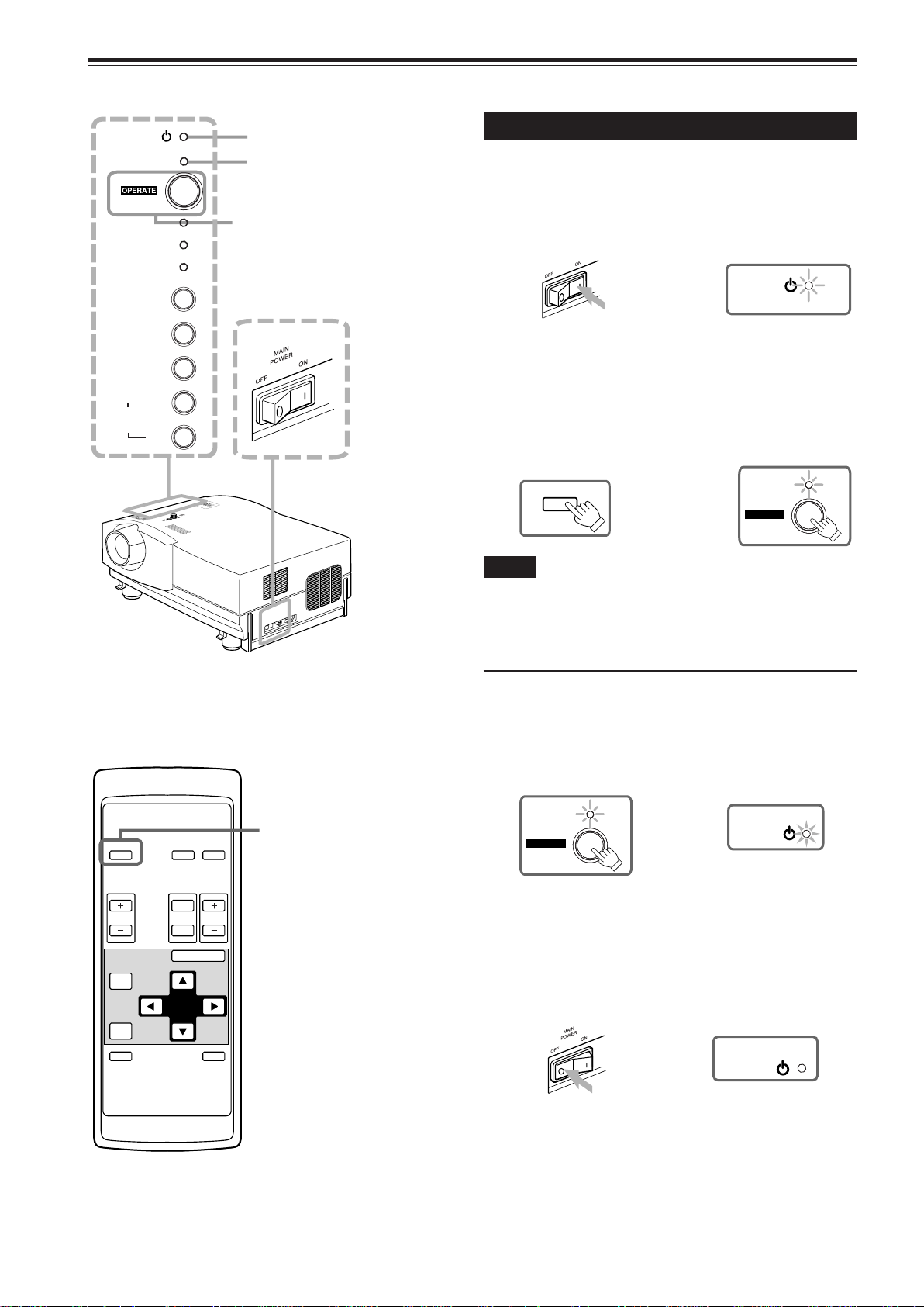
1. Turning on the Power
1 Turn on the MAIN POWER
switch.
ON [ ❙ ]:The main power turns on and the STAND BY
indicator comes on.
Projector’s indicator
STAND BY
(ON)
2 Press the OPERATE button for
one second or more.
• The OPERATE indicator comes on.
• About 30 seconds after the MAIN POWER switch is
turned on, you can start projecting.
Remote control unit Projector
OPERATE
or
(ON)
OPERATE
■ Remote control unit
OPERATE
VOL.
PAGE
BACK
PRESET
COMPUTER VIDEO
T
FOCUS
ZOOM
W
MENU/ENTER
OPERATE button
2, 1
Notes
• After the power is turned on, the screen may be jumbled for a few
seconds, but this is not a malfunction.
• If the light-source lamp does not light up, try to press the OPERA TE
button for more than a second again.
■ Turning off the Power
1 Press the OPERATE button for
one second or more.
• The STAND BY indicator changes to blinking, and the
projector goes into cool-down mode.
Example of the projector’s button Projector
(ON)
OPERATE
\
(Blinking)
STAND BY
2 Turn off the MAIN POWER switch
after the STAND BY indicator
changes to steady on.
‡‡
OFF [
‡]: The MAIN POWER switch turns off and the
‡‡
STAND BY indicator goes off.
Projector
26
QUICK
ALIGN.
AV
MUTING
(OFF)
STAND BY
* Do not turn off the MAIN POWER switch during cool
down mode (the ST AND BY indicator blinking). Turn it
off after the STAND BY indicator becomes on (standby mode).
Page 28
Basic Operations (Cont.)
COMPUTER VIDEO
■ Projector’s buttons
STAND BY
LAMP
TEMP
EMERGENCY
VIDEO
COMPUTER
SETTING
3
+
QUICK
ALIGN.
2
-
■ Remote control unit
OPERATE
VOL.
PAGE
BACK
PRESET
QUICK
ALIGN.
COMPUTER VIDEO
T
FOCUS
ZOOM
W
MENU/ENTER
AV
MUTING
VIDEO button
COMPUTER button
COMPUTER button
VIDEO button
ZOOM (T/W) buttons
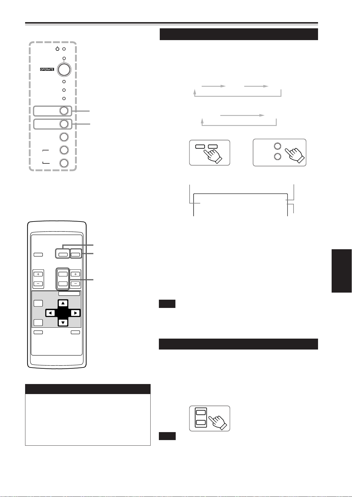
2.
Select the Video Input to be Projected
■ Press the VIDEO button or the COMPUTER button to
switch the input.
• Each time you press either button, the selected input changes as
follows.
■ When you press VIDEO:
Y/C
VIDEO
YPBPR
■ When you press COMPUTER:
COMP 1
Remote control unit Projector
Screen display
Line display
CH: 1
YPBPR NTSC(480i)
COMP 2
VIDEO
COMPUTER
Channel display
Source
display
* When the input is switched, the line display (ex. Y,PB,PR) and
the source display (ex. NTSC(480i)) are shown on the upper
part of the screen (they disappear in about five seconds).
However, they will not be shown if LINE DISPLAY in “Setting
and Adjusting Other Functions (OPTIONS)” on page 44 is set
to OFF. (For setting the source, see page 47.)
Also, when a channel is set, the channel display is shown on
the upper right corner of the screen. (For setting up channels,
see page 31,49 and 54.)
Note
• To select the proper audio input for video input
The video input terminal (AV IN input terminal) can be switched with the
VIDEO button. However, since this projector has only a single audio input
terminal, reconnect audio input in accordance with the A V device to be used.
3. Adjust the Screen Size
ENGLISH
ATTENTIONS
• DO NOT give any shock to this projector while
operating it; otherwise, the light-source lamp goes off
(the EMERGENCY indicator lights up).
If the shock turns off the light-source lamp —
Turn off the power by pressing the MAIN POWER
switch, then turn it on again. Now you can operate
the projector as usual.
■ Adjust the screen size with the remote control’s ZOOM
(T/W) buttons.
■ To enlarge the screen size:
Press the ZOOM (W) button.
■ To reduce the screen size:
Press the ZOOM (T) button.
Remote control unit
T
ZOOM
W
Note
• The adjustment of the screen size (zoom adjustment) can also be made on
the setting menu.
For operating the setting menu, refer to “Making Basic Settings” on page 32.
27
Page 29
Basic Operations (Cont.)
VOL.
■ Remote control unit
OPERATE
VOL.
PAGE
BACK
PRESET
QUICK
ALIGN.
COMPUTER VIDEO
T
ZOOM FOCUS
W
MENU/ENTER
AV
MUTING
FOCUS (+/–) buttons
VOL. (+/–) buttons
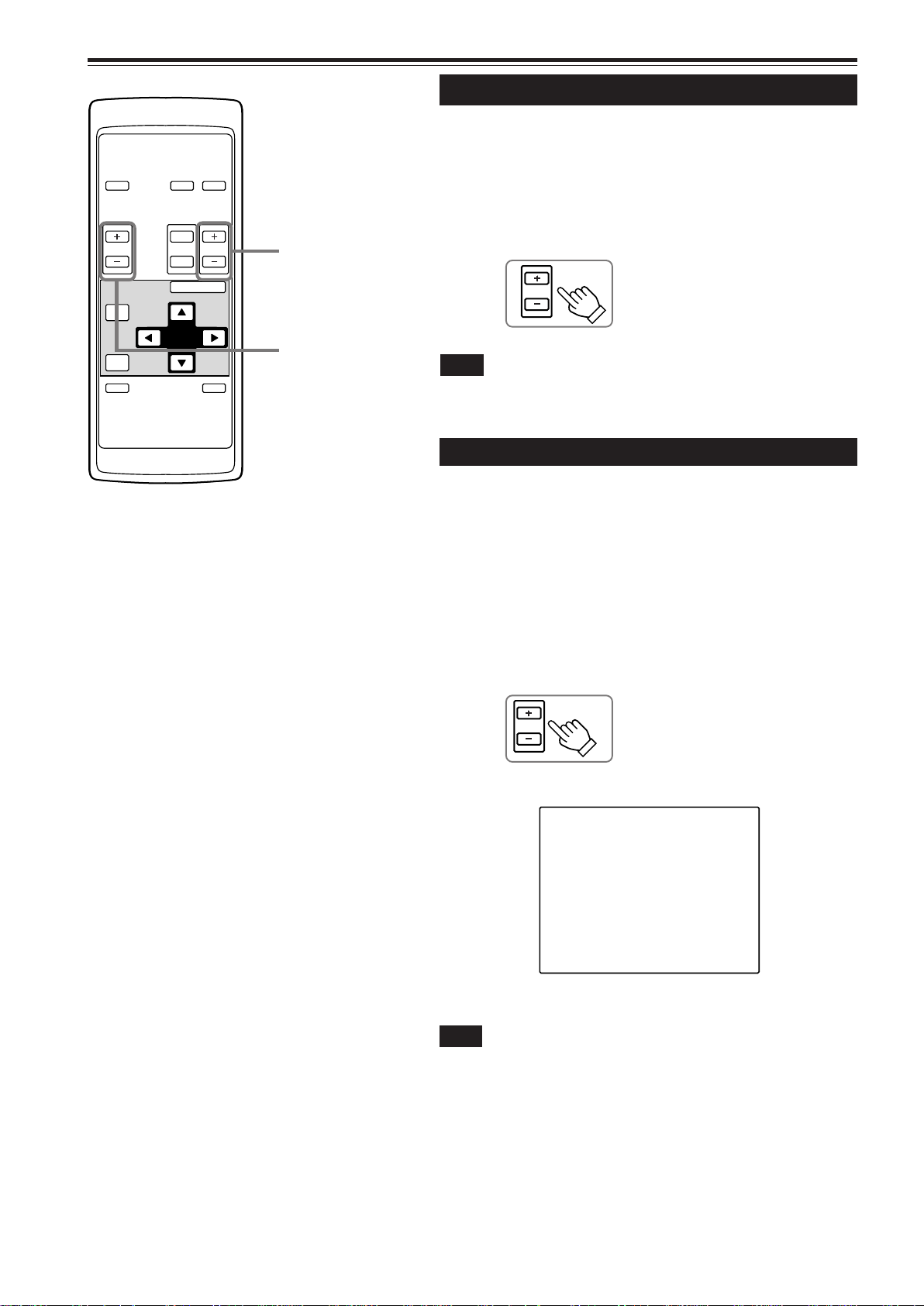
4. Adjust focus
■ Adjust focus with the remote control’s FOCUS (+/–)
buttons.
■ To focus on farther points:
Press the FOCUS (+) button.
■ To focus on nearer points:
Press the FOCUS (–) button.
Remote control unit
FOCUS
Note
• Focus adjustment can also be made on the setting menu. For operating the
setting menu, refer to “Making Basic Settings” on page 32.
5. Adjust sound volume
■ Adjust sound volume with the remote control’s VOL.
(+/–) buttons.
■ When you press the VOL. (+) button:
The sound volume becomes higher. (0 → 50)
■ When you press the VOL. (–) button:
The sound volume becomes lower. (50 → 0)
• When you press either button, the corresponding AUDIO-VOL.
level is displayed on the screen (the display will disappear in
about five seconds).
Remote control unit
Screen display
AUDIO-VOL. 25
Note
• Sound volume can be adjusted on the setting menu. For operating the setting
menu, refer to “Making Basic Settings” on page 32.
28
Page 30
Basic Operations (Cont.)
QUICK
ALIGN.
-
2
+
3
■ Remote control unit
OPERATE
VOL.
PAGE
BACK
PRESET
QUICK
ALIGN.
COMPUTER VIDEO
T
ZOOM FOCUS
W
MENU/ENTER
AV
MUTING
QUICK ALIGN. button
AV MUTING button
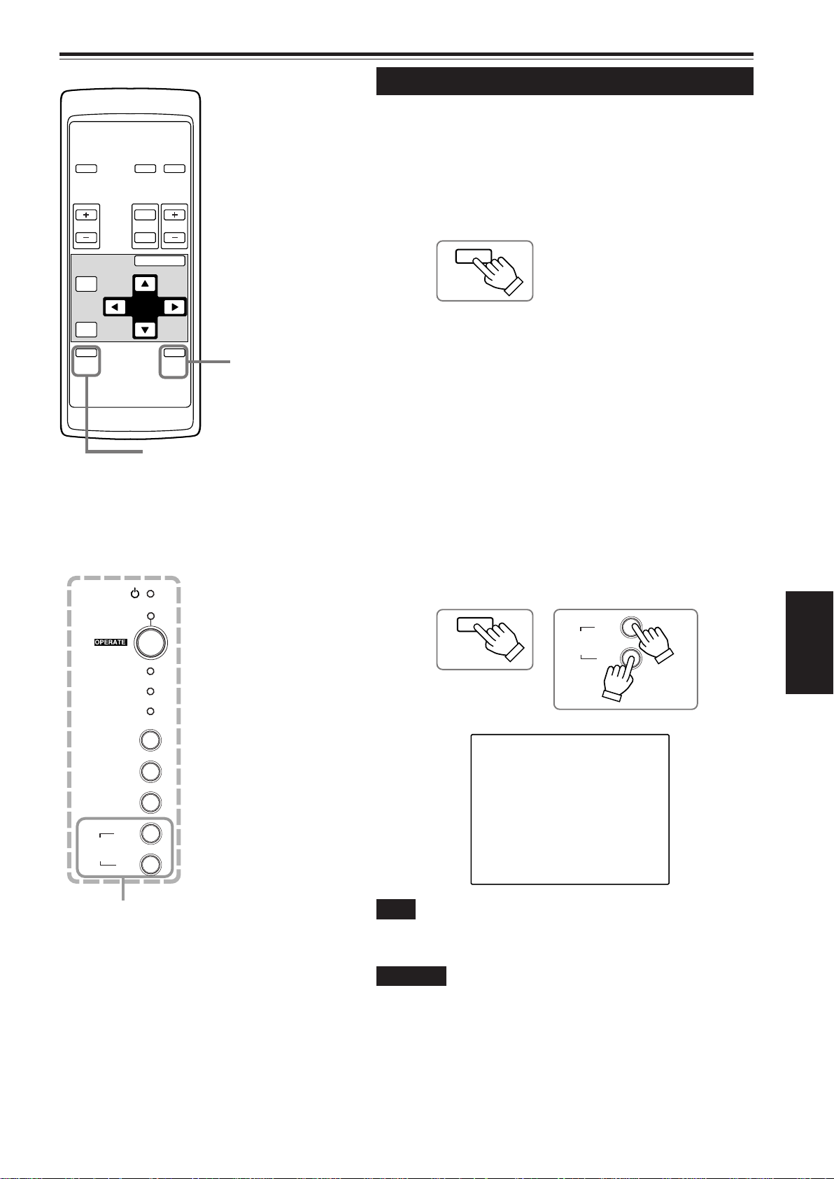
¶ For Operating Other Functions
■ To turn off video image and audio sound temporarily
Press the AV MUTING button.
■ Press once:
Video image and audio sound turn off (do not come out).
■ Press again:
Video image and audio sound come out again.
Remote control unit
AV
MUTING
■ To use the quick alignment function
The quick alignment function is used to automatically adjust (set)
the screen settings of “TRACKING, PHASE, H. POS. and V . POS.”
of computer system input video.
• Use either the remote control’s or projector’s button.
■ When using the remote control unit:
Press the QUICK ALIGN. button.
■ When using the projector:
Clear the menu display, and press the projector ’s QUICK
ALIGN. “+ 3” and “– 2” buttons at the same time.
■ Projector’s buttons
STAND BY
LAMP
TEMP
EMERGENCY
VIDEO
COMPUTER
SETTING
3
+
QUICK
ALIGN.
2
-
QUICK ALIGN. buttons
* During the automatic adjustment, “QUICK-ALIGNMENT” appears
on the screen and disappears automatically after the adjustment
is completed.
Remote control unit Projector
QUICK
ALIGN.
ENGLISH
Screen display
QUICK-ALIGNMENT
Note
• This function works only for computer system inputs.
It does not work for AV inputs.
CAUTION
• When performing automatic adjustment using the quick
alignment function:
Use a bright, still-picture screen. It may not function correctly on a
dark or motion-picture screen.
If the condition adjusted by using the quick alignment function is not
good, manually adjust TRACKING, PHASE, H. POS. and V. POS.
(see pages 32, 38 and 39).
29
Page 31

Basic Operations (Cont.)
■ Projector buttons
STAND BY
LAMP
TEMP
EMERGENCY
VIDEO
COMPUTER
SETTING
3
+
QUICK
ALIGN.
2
-
■ To display the SETTING menu
The setting menu is used to make basic adjustments and settings
(TRACKING, PHASE, H. POS., V. POS., FOCUS, ZOOM and
AUDIO-VOL.) of the video picture being projected after installation
(connection) or after inputs are switched. For operating the setting
menu, refer to “Making Basic Settings” on page 32.
• Press the projector’s SETTING button.
The setting menu is displayed on the screen.
Projector
SETTING
SETTING button
■ To display the MAIN menu
The main menu is used to adjust or set the projected video picture
and the projector’s condition, etc. (PIXEL CLOCK, POSITION,
PICTURE, SOUND, OPTIONS, SOURCE, CHANNEL, USER
SOURCE SETUP, DISPLAY SIZE, DECODER and LANGUAGE).
For operating the main menu, refer to pages 35 to 59.
• Press the remote control’s MENU/ENTER button.
The main menu appears on the screen.
■ Remote control unit
OPERATE
VOL.
PAGE
BACK
PRESET
QUICK
ALIGN.
COMPUTER VIDEO
T
ZOOM FOCUS
W
MENU/ENTER
AV
MUTING
MENU/ENTER button
Remote control unit
MENU/ENTER
Note
• To change the menu language displayed
See page 37 for “Operating the Main Menu”.
English is set when the projector is shipped from the factory. The language
displayed can be selected from the following six languages:
(Japanese), ENGLISH, DEUTSCH (German), ESPAÑOL (Spanish),
ITALIANO (Italian), and FRANÇAIS (French). However , some displays such
as “CHANNEL”, “USER SOURCE SETUP”, “DISPLAY SIZE” and “QUICKALIGNMENT” are shown only in English. Proper nouns such as line and
source displays are similarly treated.
■ To use the remote control’s PRESET button
The PRESET button is used for adjustments made on the main
menu or setting menu.
• When resetting only the selected settings to the factory-set
values, press the remote control’s PRESET button.
Only the selected item’s setting is reset to the factory-set value.
Remote control unit
PRESET
30
PRESET button
Notes
• This button works only for numeric values. It does not work for switching
between ON and OFF.
• For items such as PIXEL CLOCK (TRACKING and PHASE), POSITION (H.
POS. and V. POS.), SOUND (TREBLE and BASS), both settings are reset
at the same time.
Page 32

Basic Operations (Cont.)
■ Remote control unit
OPERATE
VOL.
PAGE
BACK
PRESET
QUICK
ALIGN.
COMPUTER VIDEO
T
ZOOM FOCUS
W
MENU/ENTER
AV
MUTING
PAGE BACK button
■ To display “CHANNEL”
When no menu is displayed, pressing P AGE BACK button
will show the channel now being used on the upper right
corner of the screen.
Also, the channel can be switched to another channel. For
details, refer to “Changing Channels” (page 54).
• When no menu is shown, press PAGE BACK button on
the remote control.
The channel is displayed on the upper right corner of the
screen.
Remote control unit
PAGE
BACK
Note
• Before you can operate the projector, channels must be set up
beforehand. For details, refer to “Setting Up Channels” on page 49.
ENGLISH
31
Page 33

Operating the Setting Menu
Making Basic Settings
■ Projector’s buttons
EMERGENCY
VIDEO
COMPUTER
SETTING
3
+
QUICK
ALIGN.
2
-
■ Setting menu
SETTING
TRACKING
PHASE
H.POS.
V.POS.
FOCUS –
ZOOM W
AUDIO -VOL.
SETTING button
QUICK ALIGN. buttons
0
0
0
0
+
T
0
Here, we make basic video adjustment and sound volume
adjustment which are set up after installation (connection).
Notes
• This adjustment menu (setting menu) can be displayed with only
the projector’s button. After displaying the setting menu, you can
select or set (adjust) items with cursor buttons on the remote control
unit.
• If settings and connections are changed, adjust and set those items
again.
• After this adjustment (setting menu), if video picture adjustment is
necessary by using the devices connected, perform the details setting
and adjustment on the main menu (pages 35 to 59).
• For computer-related inputs, use of the quick alignment function
allows automatic adjustment of TRACKING, PHASE, H. POS. and
V. POS. (See pages 29, 38 and 39).
Press the SETTING button of the
1
projector.
• The setting menu is displayed on the screen.
Press the SETTING button to
2
select the desired item.
• The selected item is shown in magenta color. Each time you
press the button, the selected item changes as follows:
TRACKING
Menu clearing AUDIO-VOL. ZOOM
PHASE H. POS. V. POS.
FOCUS
Adjustment / setting level
Description of adjustment and setting items
TRACKING : If wide vertical stripes appear on the screen,
adjust the lateral video size and display area
so that they disappear. (–255 ↔ 0 ↔ +255)
PHASE : If characters on the screen flicker or become
dim, adjust so they become clear.
(–127 ↔ 0 ↔ +127)
H. POS. : If the screen position is displaced to the right
or left, adjust the horizontal position of the
screen. (–255 ↔ 0 ↔ +255)
V. POS. : If the screen position is displaced upward or
downward, adjust the vertical position of the
screen. (–120 ↔ 0 ↔ +120)
FOCUS : Adjust the focus of video picture.
–: Focuses on near points.
+: Focuses on farther points.
ZOOM : Adjust the screen size (angle of view).
T : Becomes smaller.
W: Becomes larger.
AUDIO-VOL. : Adjust the sound level.
(0 ↔ 50)
Memo
To select items using the remote control unit:
Items can be selected using the cursor buttons 5 (backward) or
∞(forward) on the remote control unit. In this case, menu clearing in
the above order is not available. The selection changes from AUDIOVOL to TRACKING directly.
Adjust and set the selected item
3
using the QUICK ALIGN. buttons
+3or –2.
• To adjust and set multiple items, repeat steps 2 and 3.
• To reset the adjustment value of the selected item
(TRACKING, PHASE, H. POS. or V. POS.) to the
factory-set value, press the remote control’s PRESET
button. This button does not work for focus, zoom or
sound volume.
Memo
To adjust and set items using the remote control unit:
Items can be adjusted and set using the cursor buttons 2 or 3 on the
remote control unit.
Clear the setting menu by
4
pressing the SETTING button
repeatedly.
Memo
To clear the setting menu using the remote control unit:
You can also clear the setting menu by pressing the PAGE BACK
button on the remote control unit.
32
Memo
Using the quick alignment function:
This function works only for computer-related signals inputted. Press
the remote control’s QUICK ALIGN. button, or after clearing the menu
displayed, press the projector’s QUICK ALIGN. buttons “+3” and
“–2” at the same time. TRACKING, PHASE, H. POS. and V. POS.
are automatically adjusted.
During the adjustment, “QUICK-ALIGNMENT” appears on the screen,
and disappears after the adjustment finishes.
Page 34

Operating the Main Menu
Configuration of the Main Menu (AV Input)
For computer inputs, see the following page.
You can adjust video quality (PICTURE), audio quality (SOUND), etc. using the menus.
The menus are configured as follows:
Main menu (AV inputs : During AV IN input signal)
PIXEL CLOCK TRACKING : Normally, no adjustment is required. The lateral size and display area of video image are adjusted.
PHASE : Normally, no adjustment is required. Flickering or dim video image is adjusted.
POSITION V. POS. : The vertical position of the video image being projected is adjusted.
H. POS. : The horizontal position of the video image being projected is adjusted.
PICTURE BRIGHTNESS : The brightness of the video image being projected is adjusted.
CONTRAST : The contrast of the video image being projected is adjusted.
SHARPNESS : The sharpness of the video image being projected is adjusted.
COLOR : The color density of the video image being projected is adjusted.
TINT : The tint of the video image being projected is adjusted. (Displayed only for NTSC signal)
ALL RESET : All the items adjusted are reset.
SOUND TREBLE : The treble of the audio sound being input is adjusted.
BASS : The bass of the audio sound being input is adjusted.
OPTIONS MENU AUTO OFF : Sets whether to turn off menu display automatically (YES) or not (NO).
LINE DISPLAY : Sets whether to make the line display effective (ON) or not (OFF) for about 5 seconds after input
switching.
RIGHT LEFT REV.: Video image is reversed right-to-left (for upside-down hanging (ceiling)).
TOP BOTTOM INV.
CLAMP : Sets the clamp pulse’s position at the back porch (BP) or on the sync tip (ST). Normally, the clamp
RESIZE : Does not work with AV (video) input. (RESIZE is shown in gray.)
BACK COLOR : Specifies the background color when there is no video signal. Background color can be selected
COLOR TEMP. : Adjusts the color temperature of the image being projected. Make adjustment when the image
ASPECT CHANGE
SLEEP TIME : Sets the length of sleep time. A set sleep time after input signal is depleted, the projector goes into
LAMP TIME : Indicates the accumulated used hours of the light-source lamp.
: Video image is inverted top-to-bottom (for upside-down hanging (ceiling)).
pulse is used at BP. If, with some PCs or workstations, the screen becomes unstable such as
being too dark or too bright, try to switch to ST.
from BLUE, CYAN, BLACK, GREEN, MAGENTA, RED, and YELLOW.
becomes reddish or bluish.
Color temperature can be set to LOW, MIDDLE, or HIGH.
: Selects the vertical-to-horizontal ratio of the image projected. The factory-set ratio is 4 : 3. When
projecting high-vision video image, a ratio of 16 : 9 can be selected.
a stand-by state. Sleep time can be selected from 10, 20, 30, 60 and 0 minutes. (If you select 0
minutes, the sleep time will be cleared.)
ENGLISH
SOURCE : Normally used in AUT O. If use in AUTO is unstable such as color not appearing, the screen being disturbed or the
screen being intermitted, set to the dedicated source (forced mode) in accordance with the input signal.
CHANNEL : A line, multiple sources and a switcher number can be registered to a single channel. Up to 10 channels can be set.
Registered channels can be recalled by direct channel switching.
USER SOURCE SETUP : When handling some signals that are delicately different in horizontal/vertical frequency from video signals
that can be input to the projector, you can assign names to them for easy selection. Up to 10 such signals
can be registered.
DISPLAY SIZE : This does not work for AV (video) input signals. (Adjustment items are displayed in gray color.)
DECODER : Normally, set to AUTO. The color system of an input signal is automatically identified and shown in ( ). When use
in AUTO is unstable such as no color being shown, set the dedicated color system in accordance with the input
signal. You can select from AUTO, NTSC(480i), NTSC4.43, PAL, and SECAM.
LANGUAGE : Text on the screen can be changed to a language other than English. Languages that can be displayed are the
following six : (Japanese), ENGLISH, DEUTSCH (German), ESPAÑOL (Spanish), ITALIANO (Italian), and
FRANÇAIS (French). However, some displays such as “CHANNEL”, “USER SOURCE SETUP”, “DISPLAY SIZE”
and “QUICK-ALIGNMENT” are shown only in English.
33
Page 35

Operating the Main Menu (Cont.)
Configuration of the Main Menu (Computer-related input)
Main menu (Computer-related inputs : During COMPUTER IN-1 or -2 input signal)
PIXEL CLOCK TRACKING : The lateral size and display area of video image are adjusted.
PHASE : Flickering or dim video image is adjusted.
POSITION V. POS. : The vertical position of the video image being projected is adjusted.
H. POS. : The horizontal position of the video image being projected is adjusted.
PICTURE BRIGHTNESS : The brightness of the video image being projected is adjusted.
CONTRAST : The contrast of the video image being projected is adjusted.
R-GAIN : The gain in red signal of the video image being projected is adjusted.
G-GAIN : The gain in green signal of the video image being projected is adjusted.
B-GAIN : The gain in blue signal of the video image being projected is adjusted.
TEXT MODE : Adjust easiness for reading text during RESIZE.
NORMAL
TEXT 1
TEXT 2
ALL RESET : All the items adjusted are reset.
SOUND TREBLE : The treble of the audio sound being input is adjusted.
BASS : The bass of the audio sound being input is adjusted.
: Normal
: Display the outline of small letters already.
: Makes the outline of large letters sharp.
OPTIONS MENU AUTO OFF : Sets whether to turn off menu display automatically (YES) or not (NO).
LINE DISPLAY : Sets whether to make the line display effective (ON) or not (OFF) for about 5 seconds after input
switching.
RIGHT LEFT REV. : Image is reversed right-to-left (for upside-down hanging (ceiling)).
TOP BOTTOM INV.: Image is inverted top-to-bottom (for upside-down hanging (ceiling)).
CLAMP : Sets the clamp pulse’s position at the back porch (BP) or on the sync tip (ST). Normally , the clamp
pulse is used at BP. If, with some PCs or workstations, the screen becomes unstable such as
being too dark or too bright, try to switch to ST.
RESIZE : When the number of pixels (resolution) sought by the video image input is smaller than that
(resolution) of D-ILA device, the video image is then enlarged to a virtually full screen size of D-ILA
device and projected. (Resizing indication)
BACK COLOR : Specifies the background color when there is no image signal. Background color can be selected
from BLUE, CYAN, BLACK, GREEN, MAGENTA, RED, and YELLOW.
COLOR TEMP. : Adjusts the color temperature of the video image being projected. Make adjustment when the
video image becomes reddish or bluish.
Color temperature can be set to LOW, MIDDLE, or HIGH.
ASPECT CHANGE : Selects the vertical-to-horizontal ratio of the video image projected. The factory-set ratio is 4 : 3.
When projecting high-vision image, a ratio of 16 : 9 can be selected.
SLEEP TIME : Sets the length of sleep time. A set sleep time after input signal is depleted, the projector goes into
a stand-by state. Sleep time can be selected from 10, 20, 30, 60 and 0 minutes. (If you select 0
minutes, the sleep time will be cleared.)
LAMP TIME : Indicates accumulated used hours of the light-source lamp.
SOURCE : Normally used in AUT O. If use in AUTO is unstable such as color not appearing, the screen being disturbed or the
screen being intermitted, set to the dedicated source (forced mode) in accordance with the input signal.
CHANNEL : A line, multiple sources and a switcher number can be registered to a single channel. Up to 10 channels can be set.
Registered channels can be recalled by direct channel switching.
USER SOURCE SETUP : When handling some signals that are delicately different in horizontal/vertical frequency from video signals
that can be input to the projector, you can assign names to them for easy selection. Up to 10 such signals can
be registered.
DISPLAY SIZE : This works to adjust the image display size of input signals (sources), such as “horizontal effective dots (H PIXEL)”,
“vertical effective dots (V PIXEL)”, “horizontal display position (H CENTER)” and “vertical display position (V
CENTER)”.
DECODER : Does not work with computer-related inputs. (The color system is indicated in gray.)
LANGUAGE : Text on the screen can be changed to a language other than English. Languages that can be displayed are the
following six : (Japanese), ENGLISH, DEUTSCH (German), ESPAÑOL (Spanish), ITALIANO (Italian), and
FRANÇAIS (French). However, some displays such as “CHANNEL”, “USER SOURCE SETUP”, “DISPLAY SIZE”
and “QUICK-ALIGNMENT” are shown only in English.
34
Page 36

Operating the Main Menu (Cont.)
Operating the Main Menu (Basic Operation of the Main Menu)
■ Remote control unit
MENU/ENTER
AV
MUTING
button
Cursor buttons
OPERATE
VOL.
PAGE
BACK
PRESET
QUICK
ALIGN.
PAGE BACK button
COMPUTER VIDEO
T
ZOOM FOCUS
W
MENU/ENTER
For projector’s menus, the setting menu and the main menu are
available.
Here, we explain about the operation of the main menu.
For the setting menu, refer to “Making Basic Settings” on page 32.
Press the MENU/ENTER button.
1
• The main menu is displayed on the screen.
Select an item with the cursor button
2
5 or ∞.
• The selected item (displayed text) is shown in magenta color
on the screen.
Set (adjust) the item.
3
■ When you have selected DECODER or LANGUAGE,
• Set it with the cursor button 2 or 3.
* To finish the main menu, press the PAGE BACK button.
■ When you have selected an item on the submenu,
• Press the MENU/ENTER button to display the submenu, then
set (adjust) the item with the cursor buttons 2 / 3 or 5 / ∞.
* To return to the main menu, press PAGE BACK again. (To
finish the main menu from the submenu, press P AGE BACK
twice.)
■ Main menu
(Example: During video signal input)
Channel display
Input line
CH: 1
YPBPR NTSC(480i)
PIXEL CLOCK
POSITION
PICTURE
SOUND
OPTIONS
SOURCE
CHANNEL
USER SOURCE SETUP
DISPLAY SIZE
DECODER AUTO(NTSC(480i))
LANGUAGE ENGLISH
Decoder (color system)
Language
Note
• Signal names shown in the source display are uniquely given
to specific horizontal and vertical frequencies and do not
necessarily represent the indication or type of input signals.
For example, when AUTO is selected, the horizontal and
vertical frequency signals of the signal being input are
detected, and the matching name is shown.
As mentioned above, remember that the source display does
not necessarily correspond to the indication or type of input
signals.
Source
Submenu items
■ About main menu display:
Line display: The selected input-mode designation is
displayed. For input-mode designation, “Y/
C”, “VIDEO”, “YPBPR”, “COMP 1” and
“COMP 2” are available.
Source display: The type of the signal being input is
displayed. The signal name to display can
be selected from a submenu, “Source
Setup”, AUTO mode, dedicated mode
(forced mode) or USER mode can be
selected.
Channel display: The channel selected by the user is dis-
played. Channels have lines, sources and
switcher numbers registered. By specifying
a registered source, the user can switch to
the source and line which he has set up.
If you are using a switcher, you can also
specify switcher numbers. For details, see
pages 49 to 53.
Submenu item display:
PIXEL CLOCK: See page 38.
POSITION : See page 39.
PICTURE : See pages 40 to 42.
SOUND : See page 43.
OPTIONS : See pages 44 to 46.
SOURCE : See pages 47 and 48.
CHANNEL : See pages 49 to 55.
USER SOURCE SETUP
: See pages 56 and 58.
DISPLAY SIZE: See page 59.
Decoder (Color system) display: See page 36.
Language display : See page 37.
ENGLISH
35
Page 37

Operating the Main Menu (Cont.)
Changing the Color System
■ Remote control unit
MENU/ENTER
OPERATE
VOL.
PAGE
BACK
PRESET
QUICK
ALIGN.
PAGE BACK button
COMPUTER VIDEO
T
ZOOM FOCUS
W
MENU/ENTER
MUTING
button
Cursor buttons
AV
AUTO is set for the color system when the projector is shipped from
the factory . Normally , use it in AUTO. If operation in AUTO is unstable
such as with color not being shown, set to a dedicated color system
in accordance with the color system of the signal being input.
Press the MENU/ENTER button.
1
• The main menu is shown on the screen.
Select “DECODER” with the cursor
2
button 5 or ∞.
• The selected item (displayed in text) is shown in magenta color
on the screen.
Set the color system with the cursor
3
button 2 or 3.
• Each time you press the cursor button 2 or 3, the color system
changes as follows.
3 : Forward / 2 : Backward
AUTO................... Normally, set to AUTO. The color
system of a signal being input is
automatically identified.
■ Main menu
CH: 1
YPBPR NTSC(480i)
PIXEL CLOCK
POSITION
PICTURE
SOUND
OPTIONS
SOURCE
CHANNEL
USER SOURCE SETUP
DISPLAY SIZE
DECODER AUTO(NTSC(480i))
LANGUAGE ENGLISH
Color system (DECODER) display
Note
• When computer-related signal is input, the display of the
color system is changed to gray color, making operation
impossible. When video signals from AV devices are input,
the item for the color system can be set.
NTSC (480i)......... Dedicated to NTSC (480i).
NTSC4.43 ............ Dedicated to NTSC4.43.
PAL ...................... Dedicated to PAL.
SECAM ................ Dedicated to SECAM.
Memo
About automatic signal identification
• AUTO is selected when shipped from the factory . In AUTO, the color system
(DECODER) of the signal being input is automatically identified and indicated
in ( ).
• If operation in AUT O is unstable such as with color not being shown, set to a
dedicated color system in accordance with the color system of the signal
being input. When the dedicated color system is set, be careful as automatic
identification does not work.
¶ T o finish the main menu, press the PAGE B ACK
button.
36
Page 38

Operating the Main Menu (Cont.)
Changing the Language Display
■ Remote control unit
MENU/ENTER
AV
MUTING
button
Cursor buttons
OPERATE
VOL.
PAGE
BACK
PRESET
QUICK
ALIGN.
PAGE BACK button
COMPUTER VIDEO
T
ZOOM FOCUS
W
MENU/ENTER
The language in the menu display is set to English when shipped
from the factory . When you want to change to another language, set
it as follows.
Press the MENU/ENTER button.
1
• The main menu is shown on the screen.
Select “LANGUAGE” with the cursor
2
button 5 or ∞.
• The selected item (displayed in text) is shown in magenta color
on the screen.
Set the desired language with the
3
cursor button 2 or 3.
• Each time you press the cursor button 2 or 3, the selected
language changes as follows.
3 : Forward / 2 : Backward
............ Japanese
............ English
■ Main menu
CH: 1
YPBPR NTSC(480i)
PIXEL CLOCK
POSITION
PICTURE
SOUND
OPTIONS
SOURCE
CHANNEL
USER SOURCE SETUP
DISPLAY SIZE
DECODER AUTO(NTSC(480i))
LANGUAGE ENGLISH
Language display
Note
• The selected item is shown in magenta color. Items shown
in gray cannot be operated or set in the current mode.
............ German
............ Spanish
............ Italian
ENGLISH
............ French
Memo
About language display
English is selected when the projector is shipped from the factory. The
languages in the menu display are the following six : (Japanese),
ENGLISH, DEUTSCH (German), ESPAÑOL (Spanish), IT ALIANO (Italian) and
FRANÇAIS (French).
However, some displays such as “CHANNEL”, “USER SOURCE SETUP”,
“DISPLA Y SIZE” and “QUICK-ALIGNMENT” are shown only in English. Proper
nouns such as line and source displays are similarly treated.
¶ T o finish the main menu, press the PAGE B ACK
button.
37
Page 39

Operating the Main Menu (Cont.)
Adjusting the Pixel Clock
■ Remote control unit
MENU/ENTER
OPERATE
VOL.
PAGE
BACK
PRESET
QUICK
ALIGN.
PAGE BACK button
COMPUTER VIDEO
T
ZOOM FOCUS
W
MENU/ENTER
MUTING
button
Cursor buttons
AV
The pixel clock should be adjusted mainly for computer-related inputs.
(Normally, it does not need to be adjusted for video inputs.) If a wide
stripe appears on the screen, adjust the lateral size of video image
and the display area (tracking adjustment) so the stripe disappears.
Also, if text on the video screen appears flickering or dim, make
adjustment so it becomes clear (phase adjustment).
Press the MENU/ENTER button.
1
• The main menu appears on the screen.
Select “PIXEL CLOCK ” with the cur sor
2
button 5 or ∞.
• The selected item (displayed in text) is shown in magenta color
on the screen.
Press the MENU/ENTER button.
3
• The submenu items of the PIXEL CLOCK menu appear on the
screen.
PIXEL CLOCK
TRACKING PHASE
0 0
■ Main menu
CH: 1
COMP1 SXGA2
PIXEL CLOCK
POSITION
PICTURE
SOUND
OPTIONS
SOURCE
CHANNEL
USER SOURCE SETUP
DISPLAY SIZE
DECODER AUTO( )
LANGUAGE ENGLISH
Submenu item (PIXEL CLOCK)
Notes
• The selected item is shown in magenta color. Items shown
in gray color cannot be operated or set in the current mode.
• A dim screen could be caused by insufficient adjustment of
brightness and contrast. Before adjusting phase, make sure
that brightness and contrast are correctly adjusted.
(PIXEL CLOCK menu)
Adjust “TRA CKING” and “PHASE” with
4
the cursor buttons.
• Adjust the tracking and phase of the video screen being
projected. To adjust the phase, first check for correct tracking
adjustment.
Adjustment item Button Adjustment content
The screen shrinks laterally
2
TRACKING
PHASE
(right-to-left). (–255 ← 0 ← +255)
The screen extends laterally
3
(left-to-right). (–255 → 0 → +255)
Set to a position where text
appears clear.
(–127 → 0 → +127)
5
(–127 ← 0 ← +127)
∞
* To reset to the factory-set adjustment values, press the remote
control’s PRESET button.
Tracking and phase are reset to the factory-set adjustment values.
¶ To return to the main menu, press the PAGE
BACK button. To finish the main menu, press
PAGE BACK again.
• To finish the menu display from the submenu display (PIXEL
CLOCK menu), press PAGE BACK twice.
38
Page 40

Operating the Main Menu (Cont.)
Adjusting the Screen Position
■ Remote control unit
MENU/ENTER
AV
MUTING
button
Cursor buttons
OPERATE
VOL.
PAGE
BACK
PRESET
QUICK
ALIGN.
PAGE BACK button
COMPUTER VIDEO
T
ZOOM FOCUS
W
MENU/ENTER
Adjust the position of the screen if it is displaced.
Press the MENU/ENTER button.
1
• The main menu appears on the screen.
Select “POSITION” with the cursor
2
button 5 or ∞.
• The selected item (displayed in text) is shown in magenta color
on the screen.
Press the MENU/ENTER button.
3
• The submenu items of the POSITION menu appear on the
screen.
POSITION
H.POS. H.POS.
0 0
(POSITION menu)
■Main menu
CH: 1
VIDEO NTSC(480i)
PIXEL CLOCK
POSITION
PICTURE
SOUND
OPTIONS
SOURCE
CHANNEL
USER SOURCE SETUP
DISPLAY SIZE
DECODER AUTO(NTSC(480i))
LANGUAGE ENGLISH
Submenu item (POSITION)
Note
• The selected item is shown in magenta color. Items shown
in gray color cannot be operated or set in the current mode.
Adjust “H. POS.” and “V. POS.” with the
4
cursor buttons.
• Adjust the horizontal and vertical positions of the video picture
screen being projected.
Adjustment item Button Adjustment content
The screen moves to the left.
2
H. POS.
V. POS.
(–255 ← 0 ← +255)
The screen moves to the right.
3
(–255 → 0 → +255)
The screen moves upwards.
5
(–120 → 0 → +120)
The screen moves downwards.
∞
(–120 ← 0 ← +120)
* To reset to the factory-set adjustment values, press the remote
control’s PRESET button. H. POS. and V. POS. are reset to the
factory-set adjustment values.
¶ To return to the main menu, press the PAGE
BACK button. To finish the main menu, press
PAGE BACK again.
• To finish the menu display from the submenu display (POSITION
menu), press PAGE BACK twice.
ENGLISH
39
Page 41

Operating the Main Menu (Cont.)
Adjusting Picture Quality
■ Remote control unit
MENU/ENTER
OPERATE
VOL.
PAGE
BACK
PRESET
QUICK
ALIGN.
COMPUTER VIDEO
T
ZOOM FOCUS
W
MENU/ENTER
PAGE BACK button
MUTING
button
Cursor buttons
AV
Adjust brightness, contrast, etc. so you have the desired screen.
Adjustment items (on the PICTURE menu) are different when videorelated signals are input and when computer-related signals are input.
Press the MENU/ENTER button.
1
• The main menu appears on the screen.
Select “PICTURE” with the cursor
2
button 5 or ∞.
• The selected item (displayed in text) is shown in magenta color
on the screen.
Press the MENU/ENTER button.
3
• The submenu items of the PICTURE menu appear on the
screen.
■When AV signals are input
PICTURE
(NTSC(480i))
BRIGHTNESS
CONTRAST
SHARPNESS
COLOR –
TINT 1
ALL RESET
0
0
3
3
■ Main menu
CH: 1
VIDEO NTSC(480i)
PIXEL CLOCK
POSITION
PICTURE
SOUND
OPTIONS
SOURCE
CHANNEL
USER SOURCE SETUP
DISPLAY SIZE
DECODER AUTO(NTSC(480i))
LANGUAGE ENGLISH
Submenu item (PICTURE)
Notes
• The selected item is shown in magenta color. Items shown
in gray color cannot be operated or set in the current mode.
• Adjustment items (on the PICTURE menu) are different when
AV signals are input and when computer-related signals are
input.
(PICTURE menu)
■When computer-related signals are input
PICTURE
(SXGA2)
BRIGHTNESS
CONTRAST
R-GAIN
G-GAIN
B-GAIN
TEXT MODE NORMAL
ALL RESET
(PICTURE menu)
Select the item to adjust with the cursor
4
button 5 or ∞.
• The item to adjust (shown in text) is displayed in magenta color.
0
0
0
0
0
40
Page 42

Operating the Main Menu (Cont.)
Adjusting Picture Quality (Cont.)
■Remote control unit
MENU/ENTER
OPERATE
VOL.
PAGE
BACK
PRESET
COMPUTER VIDEO
T
ZOOM FOCUS
W
MENU/ENTER
button
Cursor buttons
QUICK
ALIGN.
AV
MUTING
PAGE BACK button
■Submenu items
[PICTURE menu]
PICTURE
(NTSC(480i))
BRIGHTNESS
CONTRAST
SHARPNESS
COLOR –
TINT 1
ALL RESET
Make adjustment with the cursor
5
button 2 or 3.
■For video system input
• To adjust multiple items, repeat steps 4 and 5.
• To reset all items (to factory-set adjustment values “0”), select
ALL RESET with the cursor buttons and press the MENU/
ENTER button.
• To reset only the selected items (ALL RESET excluded) to
the factory-set adjustment value, press the remote control’s
PRESET button. The selected item is reset to the factory-set
adjustment value.
Adjustment item Button Adjustment content
Gets darker.
2
BRIGHTNESS
CONTRAST
SHARPNESS
COLOR
TINT
0
0
3
3
ALL RESET
MENU/
ENTER
(–30 ← 0 ← +30)
Gets brighter.
3
(–30 → 0 → +30)
Gets lower.
2
(–30 ← 0 ← +30)
Gets higher.
3
(–30 → 0 → +30)
Gets softer.
2
(0 ← 7)
Gets sharper.
3
(0 → 7)
Gets softer.
2
(–30 ← 0 ← +30)
Gets deeper.
3
(–30 → 0 → +30)
Gets reddish.
2
(–30 ← 0 ← +30)
Gets greenish.
3
(–30 → 0 → +30)
Resets all adjustment values of
items on the PICTURE menu to
the factory-set values (0).
ENGLISH
Notes
• The selected item is shown in magenta color. Items shown
in gray color cannot be operated or set in the current mode.
• Adjustment items (on the PICTURE menu) are different when
AV signals are input and when computer-related signals are
input.
Notes
• The adjustment item, TINT, is displayed only for NTSC system. It is not
displayed (cannot be adjusted) when PAL or SECAM system signals are
input.
• When video signals are input to the COMPUTER IN-2 terminal, adjustment
items “COLOR” and “TINT” are indicated but cannot be adjusted.
(To be continued on the next page)
41
Page 43

Operating the Main Menu (Cont.)
NORMAL
TEXT1
TEXT2
NORMAL
TEXT1
TEXT2
Adjusting Picture Quality (Cont.)
■Remote control unit
MENU/ENTER
OPERATE
VOL.
PAGE
BACK
PRESET
COMPUTER VIDEO
T
ZOOM FOCUS
W
MENU/ENTER
button
Cursor buttons
QUICK
ALIGN.
AV
MUTING
PAGE BACK button
■Submenu items
[PICTURE menu]
PICTURE
(SXGA2)
BRIGHTNESS
CONTRAST
R-GAIN
G-GAIN
B-GAIN
TEXT MODE NORMAL
ALL RESET
0
0
0
0
0
■For computer system input
• To adjust multiple items, repeat steps 4 and 5.
• To reset all items (to factory-set adjustment values “0”), select
ALL RESET with the cursor buttons and press the MENU/ENTER
button.
• To reset only the selected items (ALL RESET excluded) to the
factory-set adjustment value, press the remote control’s PRESET
button. The selected item is reset to the factory-set adjustment
value.
Adjustment item Button Adjustment content
Gets darker.
2
BRIGHTNESS
CONTRAST
R-GAIN
G-GAIN
B-GAIN
TEXT MODE
ALL RESET
MENU/
ENTER
(–30 ← 0 ← +30)
Gets brighter.
3
(–30 → 0 → +30)
Gets lower.
2
(–30 ← 0 ← +30)
Gets higher.
3
(–30 → 0 → +30)
Gets less reddish.
2
(–30 ← 0 ← +30)
Gets more reddish.
3
(–30 → 0 → +30)
Gets less greenish.
2
(–30 ← 0 ← +30)
Gets more greenish.
3
(–30 → 0 → +30)
Gets less bluish.
2
(–30 ← 0 ← +30)
Gets more bluish.
3
(–30 → 0 → +30)
Sets a mode which allows easy
text reading.
2
3
Resets all adjustment values of
items on the PICTURE quality
menu to the factory-set status
(adjustment values: 0, text
mode: NORMAL).
Notes
• The selected item is shown in magenta color. Items shown
in gray color cannot be operated or set in the current mode.
• Adjustment items (on the PICTURE menu) are different when
AV signals are input and when computer-related signals are
input.
42
Note
• There is a relationship between the adjustment of items R-GAIN, G-GAIN,
and B-GAIN and that of item CONTRAST. For example, when adjustment
values are : R-GAIN: 0, G-GAIN: 5, B-GAIN: 0, and CONTRAST : 0, changing
CONTRAST to 1 changes the adjustment values as follows: R-GAIN: 1, GGAIN: 6, and B-GAIN: 1.
Also, when the adjustment value of any of R-GAIN, G-GAIN, and B-GAIN
has reached -30 (minimum) or +30 (maximum), CONTRAST cannot be
adjusted to any higher value. For example, when R-GAIN is 0, G-GAIN is 5,
B-GAIN is 0, and CONTRAST is 0, increasing CONTRAST allows the other
adjustment values to increase until R-GAIN: 25, G-GAIN: 30, and B-GAIN:
25, then CONTRAST becomes 25 and cannot be adjusted to any higher
value.
¶ To return to the main menu, press the PAGE
BACK button. To finish the main menu, press
PAGE BACK again.
• To finish the menu display from the submenu display (PICTURE
menu), press PAGE BACK twice.
Page 44

Operating the Main Menu (Cont.)
Adjusting Sound Quality
■ Remote control unit
MENU/ENTER
AV
MUTING
button
Cursor buttons
OPERATE
VOL.
PAGE
BACK
PRESET
QUICK
ALIGN.
PAGE BACK button
COMPUTER VIDEO
T
ZOOM FOCUS
W
MENU/ENTER
Adjust the quality (treble/bass) of sound.
Press the MENU/ENTER button.
1
• The main menu appears on the screen.
Select “SOUND” with the cursor button
2
5 or ∞.
• The selected item (displayed in text) is shown in magenta color
on the screen.
Press the MENU/ENTER button.
3
•The submenu items of the SOUND menu appear on the screen.
SOUND
TREBLE BASS
0 0
(SOUND menu)
■ Main menu
CH: 1
VIDEO NTSC(480i)
PIXEL CLOCK
POSITION
PICTURE
SOUND
OPTIONS
SOURCE
CHANNEL
USER SOURCE SETUP
DISPLAY SIZE
DECODER AUTO(NTSC(480i))
LANGUAGE ENGLISH
Submenu item (SOUND)
Note
• The selected item is shown in magenta color. Items shown
in gray color cannot be operated or set in the current mode.
Adjust “TREBLE” and “B ASS” with the
4
cursor buttons.
• Adjust the quality (TREBLE and BASS) of sound.
Adjustment item Button Adjustment content
Gets weaker.
2
3
5
∞
(–5 ← 0 ← +5)
Gets stronger.
(–5 → 0 → +5)
Gets stronger.
(–5 → 0 → +5)
Gets weaker.
(–5 ← 0 ← +5)
TREBLE
BASS
* To reset to the factory-set adjustment values, press the remote
control’s PRESET button. The treble and bass are reset to the
factory-set adjustment values.
¶ To return to the main menu, press the PAGE
BACK button. To finish the main menu, press
PAGE BACK again.
• To finish the menu display from the submenu display (SOUND
menu), press PAGE BACK twice.
ENGLISH
43
Page 45

Operating the Main Menu (Cont.)
Setting and Adjusting Other Functions (OPTIONS)
■ Remote control unit
MENU/ENTER
OPERATE
VOL.
PAGE
BACK
PRESET
QUICK
ALIGN.
COMPUTER VIDEO
T
ZOOM FOCUS
W
MENU/ENTER
PAGE BACK button
MUTING
button
Cursor buttons
AV
The following optional functions can be set (adjusted).
• MENU AUTO OFF • LINE DISPLAY • RIGHT LEFT REV.
• TOP BOTTOM INV. • CLAMP • RESIZE
• BACK COLOR • COLOR TEMPERA TURE
• ASPECT CHANGE • SLEEP TIME • LAMP TIME
Memo
About the lamp use time (LAMP TIME)
The lamp use time indicates the accumulated used hours of the light-source
lamp and cannot be set or adjusted. When you have replaced with a new
light-source lamp, reset the lamp use time (see page 63).
Note
• The RESIZE function works for only computer system input. It does not work
for video system input.
Press the MENU/ENTER button.
1
• The main menu appears on the screen.
Select “OPTIONS” with the cursor
2
button 5 or ∞.
• The selected item (displayed in text) is shown in magenta color
on the screen.
■ Main menu
CH: 1
YPBPR NTSC(480i)
PIXEL CLOCK
POSITION
PICTURE
SOUND
OPTIONS
SOURCE
CHANNEL
USER SOURCE SETUP
DISPLAY SIZE
DECODER AUTO(NTSC(480i))
LANGUAGE ENGLISH
Submenu item (OPTIONS)
Notes
• The selected item is shown in magenta color. Items shown
in gray color cannot be operated or set in the current mode.
• Items to be set (adjusted) are different when AV signals are
input and when computer system signals are input.
Press the MENU/ENTER button.
3
• The submenu items of the OPTIONS menu are displayed.
OPTIONS
MENU AUTO OFF
LINE DISPLAY
RIGHT LEFT REV.
TOP BOTTOM INV.
CLAMP
RESIZE
BACK COLOR
COLOR TEMP.
ASPECT CHANGE
SLEEP TIME
LAMP TIME
NO
ON
OFF
OFF
BP
ON
BLUE
MIDDLE
4:3
30 Min.
10 H.
(OPTIONS menu)
Select the item to set (adjust) with the
4
cursor button 5 or ∞.
• The item to set (adjust) is shown in magenta color.
44
Page 46

Operating the Main Menu (Cont.)
Setting and Adjusting Other Functions (OPTIONS) (Cont.)
■Remote control unit
MENU/ENTER
OPERATE
VOL.
PAGE
BACK
PRESET
COMPUTER VIDEO
T
ZOOM FOCUS
W
MENU/ENTER
button
Cursor buttons
QUICK
ALIGN.
AV
MUTING
PAGE BACK button
■Submenu items
[OPTIONS menu]
OPTIONS
MENU AUTO OFF
LINE DISPLAY
RIGHT LEFT REV.
TOP BOTTOM INV.
CLAMP
RESIZE
BACK COLOR
COLOR TEMP.
ASPECT CHANGE
SLEEP TIME
LAMP TIME
Notes
• The selected item is shown in magenta color. Items shown
in gray color cannot be operated or set in the current mode.
• Items to be set (adjusted) are different when AV signals are
input and when computer-system signals are input.
• When you turn the RESIZE function ON, allowing the screen
to be enlarged virtually to its full size for projection (resizing
display), the video image (resolution) becomes coarse.
NO
ON
OFF
OFF
BP
ON
BLUE
MIDDLE
4:3
30 Min.
10 H.
Set (adjust) the desired item with the
5
cursor button 2 or 3.
• To adjust multiple items, repeat steps 4 and 5.
Adjustment item Button Adjustment content
Sets whether to clear the menu display
automatically a fixed time later or not.
(Factory setting : NO)
MENU AUT O
OFF
LINE DISPLAY
RIGHT LEFT
REV.
TOP BOTTOM
INV.
CLAMP
RESIZE
YES: Clears the display automatically in
2/3
2/3
2/3
2/3
2/3
2/3
about 25 seconds.
NO : Does not clear the display
automatically.
NO YES
Sets whether to show the line display (Y/C,
VIDEO, etc.) at the top of the projected
screen or not. (Factory setting : ON)
OFF: Does not show the line display.
ON : Shows the line display.
(The line display disappears about 5
seconds after it is shown.)
OFF ON
Reverses video image right-to-left.
(Factory setting : OFF)
OFF: For the front method
ON : For upside hanging from the ceiling
OFF ON
Inverses video image upside-down.
(Factory setting : OFF)
OFF: For normal set-up
ON : For upside hanging from the ceiling
OFF ON
Sets the clamp pulse’s position at the back
porch (BP) or on the sync tip (ST).
Normally, the clamp is used at BP. If, with
some PCs or workstations, the screen
becomes unstable such as being too dark
or too bright, try to switch to ST.
(Factory setting: BP)
BP : The clamp pulse is positioned at the
back porch.
ST : The clamp pulse is positioned on the
sync tip.
BP ST
When the number of pixels (resolution)
sought by the input video is smaller than
that (resolution) of D-ILA device, the video
image is then enlarged to virtually full
screen size of D-ILA device and projected
(resizing display). (Factory setting : ON)
Does not work (cannot be set) for video
system input.
OFF : Does not enlarge the video image for
projection. When the number of
pixels sought by video image is
smaller than that of D-ILA device,
projection takes place on a small
screen size with a black area around
the screen.
ON : Enlarges virtually to the full screen
size of D-ILA device for projection
(resizing display).
OFF ON
ENGLISH
(To be continued on the next page)
45
Page 47

Operating the Main Menu (Cont.)
Setting and Adjusting Other Functions (OPTIONS) (Cont.)
■Remote control unit
MENU/ENTER
OPERATE
VOL.
PAGE
BACK
PRESET
COMPUTER VIDEO
T
ZOOM FOCUS
W
MENU/ENTER
button
Cursor buttons
QUICK
ALIGN.
AV
MUTING
PAGE BACK button
■Submenu items
[OPTIONS menu]
Adjustment item Button Adjustment content
Sets background color when there is no input
signal. (Factory setting : BLUE)
BACK COLOR
BLUE CYAN BLACK GREEN
2/3
YELLOW RED MAGENTA
Sets the color temperature of the video image
being projected. Make adjustment when the
image becomes reddish or bluish.
(Factory setting : MIDDLE)
LOW : Color temperature decreases
COLOR
TEMP.
2/3
MIDDLE: Results in middle color
(video image becoming reddish).
temperature.
HIGH : Color temperature increases
(video image becoming bluish).
LOW MIDDLE HIGH
Sets the vertical-to-horizontal ratio (4 : 3 or 16
: 9) of the video image projected.
(Factory setting : 4 : 3)
4 : 3 : The aspect ratio of the screen
ASPECT
CHANGE
2/3
becomes 4 : 3. Set it to 4 : 3 for video
of NTSC, NTSC4.43, PAL, SECAM.
16 : 9: The aspect ratio of the screen
becomes 16 : 9. Set it to 16 : 9 for HiVision devices (W-VHS VCR, etc.)
4 : 3 16 : 9
Sets the length of sleep time which
automatically brings the projector into standby state. Y ou can select one of the sleep
SLEEP TIME
2/3
times: 10, 20, 30, 60 and 0 minutes.
(Factory setting: 30 minutes)
10 20 30 60 0
OPTIONS
MENU AUTO OFF
LINE DISPLAY
RIGHT LEFT REV.
TOP BOTTOM INV.
CLAMP
RESIZE
BACK COLOR
COLOR TEMP.
ASPECT CHANGE
SLEEP TIME
LAMP TIME
NO
ON
OFF
OFF
BP
ON
BLUE
MIDDLE
4:3
30 Min.
10 H.
Notes
• The selected item is shown in magenta color. Items shown
in gray color cannot be operated or set in the current mode.
• Items to be set (adjusted) are different when AV signals are
input and when computer-system signals are input.
If you select 0 minutes, this function does not
work.
¶ To return to the main menu, press the PAGE
BACK button. To finish the main menu, press
PAGE BACK again.
• To finish the menu display from the submenu display (OPTIONS
menu), press PAGE BACK twice.
Note
• When you view a conventional (normal) 4 :3 video picture, which is not wide
video picture, on the projector’s screen using the aspect change function,
the upper and lower parts of the video picture become partially invisible.
View such an original video picture in 4 :3 mode, respecting the producer’s
intention.
46
Page 48

Operating the Main Menu (Cont.)
Changing (Setting) the Source
■ Remote control unit
MENU/ENTER
AV
MUTING
button
Cursor buttons
OPERATE
VOL.
PAGE
BACK
PRESET
QUICK
ALIGN.
COMPUTER VIDEO
T
ZOOM FOCUS
W
MENU/ENTER
PAGE BACK button
Normally, use the source setting in AUTO. If use in AUT O is unstable
such as color not appearing, the screen being disturbed or the screen
being intermitted, set to the dedicated source (forced mode) in
accordance with the input signal.
Also, User Source Setup mode, which lets you set up special signals,
is available.
• When shipped from the factory, the source settings are as follows:
Input mode Factory setting Input mode Factory setting
VIDEO NTSC (480i) COMP 1 AUTO
Y/C NTSC (480i) COMP 2 AUTO
YPBPR AUTO — —
Notes
• Depending on the signal from a device connected, adjustment may be needed
after a dedicated source is set. If that is the case, adjust the appropriate
items.
• When the input mode (SOURCE) is VIDEO or Y/C, and if AUTO is set, the
automatic detecting function may work, possibly causing the screen to be
intermitted or disturbed. In that case, set to a dedicated source (forced mode).
• When special effect playback (fast-forward/ twice-speed/triple-speed) is
performed on a VCR, etc, the picture may be disturbed or intermitted,
depending on the device.
• When inputting 480p or 720p-DTV-format signal in COMP 2 input mode,
use the dedicated source mode “SDTV (480p)” or “HDTV (720p)”. (In
AUTO, 480p or 720p signal can not be detected.)
■Main menu
CH: 1
VIDEO NTSC(480i)
PIXEL CLOCK
POSITION
PICTURE
SOUND
OPTIONS
SOURCE
CHANNEL
USER SOURCE SETUP
DISPLAY SIZE
DECODER AUTO(NTSC(480i))
LANGUAGE ENGLISH
Submenu item [SOURCE]
Notes
• The selected item is shown in magenta color. Items shown
in gray color cannot be operated or set in the current mode.
• Items that can be set are different when video signals are
input and when computer signals are input.
• For dedicated source signals (corresponding frequency, etc.)
for computer signals, see page 19.
Press the MENU/ENTER button.
1
• The main menu appears on the screen.
Select a submenu item “SOURCE”
2
using the cursor button 5 or ∞.
• The SOURCE item (displayed in text) is indicated in magenta
color.
Press the MENU/ENTER button.
3
• The submenu, SOURCE menu, appears on the screen.
SOURCE
(SXGA1)
AUTO
NTSC(480i)
SDTV(480p)
HDTV(720p)
HDTV(1080i)
PAL/SECAM
PC-98
VGA1
VGA3
MAC13
VGA VESA
SVGA1
SVGA2
MAC16
XGA1
XGA2
MAC19
MAC21
SXGA1
SXGA2
SXGA3
USER
The display in ( ) shows
the currently set status.
(SOURCE menu)
Select the item to set using the cursor
4
buttons 5/∞ or 2/3.
• The item to set is shown in magenta color.
SOURCE
(SXGA1)
AUTO
NTSC(480i)
SDTV(480p)
HDTV(720p)
HDTV(1080i)
PAL/SECAM
PC-98
VGA1
VGA3
MAC13
VGA VESA
SVGA1
SVGA2
MAC16
XGA1
XGA2
MAC19
MAC21
SXGA1
SXGA2
SXGA3
USER
ENGLISH
(To be continued on the next page)
47
Page 49

Operating the Main Menu (Cont.)
Changing (Setting) the Source (Cont.)
■ Remote control unit
MENU/ENTER
OPERATE
VOL.
PAGE
BACK
PRESET
QUICK
ALIGN.
COMPUTER VIDEO
T
ZOOM FOCUS
W
MENU/ENTER
PAGE BACK button
MUTING
button
Cursor buttons
AV
Press the MENU/ENTER button to set
5
(fix) it.
■When AUTO is selected:
The main menu is automatically cleared, completing the
setting procedure, and the sour ce display inputted appears.
• Both line display and source display appear on the screen
and disappear in five seconds. However, they do not appear
if the line display is set to OFF.
SOURCE
(SXGA1)
AUTO
NTSC(480i)
SDTV(480p)
HDTV(720p)
HDTV(1080i)
PAL/SECAM
PC-98
VGA1
VGA3
MAC13
VGA VESA
SVGA1
SVGA2
MAC16
XGA1
XGA2
MAC19
MAC21
SXGA1
SXGA2
SXGA3
USER
CH: 1
COMP 2 SXGA1
▲
■When a dedicated source mode is selected :
The selected item is shown in ( ) below the displayed text
of “SOURCE” on the upper part of the screen.
■ Submenu item
(SOURCE menu)
SOURCE
(SXGA1)
AUTO
NTSC(480i)
SDTV(480p)
HDTV(720p)
HDTV(1080i)
PAL/SECAM
PC-98
VGA1
VGA3
MAC13
VGA VESA
Notes
• The selected item is shown in magenta color. Items shown
in gray color cannot be operated or set in the current mode.
• Items that can be set are different when video signals are
input and when computer signals are input.
• For dedicated source signals (corresponding frequency, etc.)
for computer signals, see page 19.
• To finish the menu display, press PAGE BACK Button twice
(or three times).
SVGA1
SVGA2
MAC16
XGA1
XGA2
MAC19
MAC21
SXGA1
SXGA2
SXGA3
USER
SOURCE
(SXGA1)
AUTO
NTSC(480i)
SDTV(480p)
HDTV(720p)
HDTV(1080i)
PAL/SECAM
PC-98
VGA1
VGA3
MAC13
VGA VESA
SVGA1
SVGA2
MAC16
XGA1
XGA2
MAC19
MAC21
SXGA1
SXGA2
SXGA3
USER
Source
■When USER is selected :
The USER SOURCE SETUP menu is displayed.
• This menu is used when registering and using special video
signals that cannot be adjusted in “AUTO” mode or dedicated source mode, using “USER SOURCE SETUP” (see
page 56).
• When the projector was shipped from the factory,
“HD 1035 i _ R” and “HD1035 i _ Y” were already registered.
SOURCE
(SXGA1)
AUTO
NTSC(480i)
SDTV(480p)
HDTV(720p)
HDTV(1080i)
PAL/SECAM
PC-98
VGA1
VGA3
MAC13
VGA VESA
SVGA1
SVGA2
MAC16
XGA1
XGA2
MAC19
MAC21
SXGA1
SXGA2
SXGA3
USER
1. Press the cursor buttons to select a setting.
(USER1)
USER1
HD1035i_R
HD1035i_Y
SOURCE
48
2. Press the MENU/ENTER button to set.
• When a user source is selected, the source setting of the
projector switches to a setting registered in the user source.
Page 50

Operating the Main Menu (Cont.)
Setting Up Channels
■ Remote control unit
MENU/ENTER
AV
MUTING
button
Cursor buttons
OPERATE
VOL.
PAGE
BACK
PRESET
QUICK
ALIGN.
COMPUTER VIDEO
T
ZOOM FOCUS
W
MENU/ENTER
PAGE BACK button
When you set up channels, you can select a line and multiple sources
(up to 30) for each channel. If you are using a switcher and set a
switcher numbers, you can also select each channel from the switcher
side.
Memo
• With multiple sources having been set on channels, when a channel is
selected, incoming signal is automatically checked and switched to one of
the sources registered on the channel.
If a matching source is not found among the registered sources, all other
available sources are searched to find a matching source.
Press the MENU/ENTER button.
1
• The main menu appears on the screen.
Select “CHANNEL” with the cursor
2
button 5 or ∞ .
• The selected item (displayed in text) is shown in magenta color
on the screen.
Press the MENU/ENTER button.
3
• A submenu item, CHANNEL setup menu, appears on the screen.
For items of “LINE”, “SOURCE” and “SWNo” which are not set
up, the symbol (7) is shown instead.
■Main menu
CH: 1
VIDEO NTSC(480i)
PIXEL CLOCK
POSITION
PICTURE
SOUND
OPTIONS
SOURCE
CHANNEL
USER SOURCE SETUP
DISPLAY SIZE
DECODER AUTO(NTSC(480i))
LANGUAGE ENGLISH
Submenu item [CHANNEL]
Notes
• The selected item is shown in magenta color. Items shown
in gray color cannot be operated or set in the current mode.
• Items that can be set are different when video signals are
input and when computer signals are input.
• For dedicated source signals (corresponding frequency, etc.)
for computer signals, see page 19.
CHANNEL
(AUTO)
LINE
CH
1
2
3
4
5
6
7
8
9
10
Y/C
VIDEO
77777
77777
77777
77777
77777
77777
77777
77777
SOURCE
NTSC(480i)
PAL/SECAM
777777777
777777777
777777777
777777777
777777777
777777777
777777777
777777777
SWNo
1
2
77
77
77
77
77
77
77
77
(Channel Setup menu)
Press the cursor button 5 or ∞ to select
4
the channel (CH) , then press the cursor
button 3 to move to “LINE”.
• The selected item is shown in magenta color on the screen.
• If any “LINE” item is not registered, you cannot select a
“SOURCE” or “SWNo” item.
ENGLISH
(To be continued on the next page)
49
Page 51

Operating the Main Menu (Cont.)
Setting Up Channels (Cont.)
■ Remote control unit
MENU/ENTER
OPERATE
VOL.
PAGE
BACK
PRESET
QUICK
ALIGN.
PAGE BACK button
COMPUTER VIDEO
T
ZOOM FOCUS
W
MENU/ENTER
MUTING
button
Cursor buttons
AV
Press the MENU/ENTER button to set
5
(fix).
• The LINE selection menu is shown on the screen.
LINE
Y/C
VIDEO
YPBPR
COMP1
COMP2
NONE
(LINE Selection menu)
6Press the cursor b utton 5 or ∞ to select
a “LINE” item.
• The selected item (displayed in text) is shown in magenta color
on the screen.
• The LINE item set up in this step uses the input terminal selected
when you choose a channel, using such as a “direct channel”.
Press the MENU/ENTER button to set
7
(fix).
• The display returns to the CHANNEL setup menu.
• After setting a “LINE” item, “SOURCE” and “SWNo” items can
be set.
¶ To return to the main menu, press the PAGE
BACK button. To finish the main menu, press
PAGE BACK again.
¶ To delete the contents of the channel registered
(set up)
1. Move to the line of the channel you want to delete in
step 4 and press MENU/ENTER to fix.
2. Select “NONE” from the LINE selection menu display
in step 6 and press MENU/ENTER. The “LINE”,
“SOURCE” and “SWNo” items of the selected channel
will be deleted.
50
Page 52

Operating the Main Menu (Cont.)
Setting Up Channels (Cont.)
■ Remote control unit
MENU/ENTER
OPERATE
VOL.
PAGE
BACK
PRESET
COMPUTER VIDEO
T
ZOOM FOCUS
W
MENU/ENTER
button
Cursor buttons
QUICK
ALIGN.
AV
MUTING
PAGE BACK button
■CHANNEL setup menu
CHANNEL
(AUTO)
LINE
CH
1
Y/C
2
VIDEO
3
77777
4
77777
5
77777
6
77777
7
77777
8
77777
9
77777
10
77777
SOURCE
NTSC(480i)
PAL/SECAM
777777777
777777777
777777777
777777777
777777777
777777777
777777777
777777777
SWNo
1
2
77
77
77
77
77
77
77
77
■To set up a source, “SOURCE” :
Press the cursor button 3 to move to
1
“SOURCE”.
• The main menu appears on the screen.
• If any “LINE” item is not registered, you cannot choose a
“SOURCE’ or “SWNo” item. First register a “LINE” item.
Press the MENU/ENTER button.
2
• The SOURCE setup menu is displayed on the screen.
• The “SOURCE” items that have been registered are shown with
check marks.
SOURCE
NTSC(480i)
SDTV(480p)
HDTV(720p)
HDTV(1080i)
PAL/SECAM
PC–98
VGA1
VGA3
MAC13
VGA VESA
(Source Setup menu)
Press the cursor button 5 or ∞ to select
3
the desired item, then press MENU/
SVGA1
SVGA2
MAC16
XGA1
XGA2
MAC19
MAC21
SXGA1
SXGA2
SXGA3
USER
ENTER button to set or cancel.
• Once the item is set, it is indicated with a check mark and
registered as a “SOURCE”.
• If you select a “SOURCE” item with a check mark and press
MENU/ENTER, the check mark will disappear, cancelling its
registration as a “SOURCE” item.
(When a channel is selected, the registration or setting of its
contents cannot be cleared.)
■
When “USER” is selected fr om the SOURCE setup menu :
The USER SOURCE SETUP menu appears.
• The registered user source names are indicated with check
marks.
• The source set up on the USER SOURCE SETUP menu is
used for the user source name to be set here.
ENGLISH
Notes
• The selected item is shown in magenta color. Items shown
in gray color cannot be operated or set in the current mode.
• Items that can be set are different when video signals are
input and when computer signals are input.
• For dedicated source signals (corresponding frequency, etc.)
for computer signals, see page 19.
SOURCE
USER1
USER2
USER3
USER4
USER5
USER6
USER7
USER8
HD1035i_R
HD1035i_Y
(User Source Setup menu)
1. Press the cursor button 5 or ∞ to select a source
from the “SOURCE” items.
• The selected item (displayed in text) is shown in magenta color
on the screen.
(To be continued on the next page)
51
Page 53

Operating the Main Menu (Cont.)
Setting Up Channels (Cont.)
■ Remote control unit
MENU/ENTER
OPERATE
VOL.
PAGE
BACK
PRESET
QUICK
ALIGN.
COMPUTER VIDEO
T
ZOOM FOCUS
W
MENU/ENTER
PAGE BACK button
MUTING
button
Cursor buttons
AV
2. Press the MENU/ENTER button to set.
• When the item is set, a check mark is placed next to its user
name, which is registered as a “SOURCE”.
• If you place the cursor on a “SOURCE” item with a check
mark attached and press MENU/ENTER button, the check
mark will disappear, making the item unregistered as a
“SOURCE” item.
¶ To return to the main menu, press the PAGE
BACK button. To finish the main menu, press
PAGE BACK again.
52
Page 54

Operating the Main Menu (Cont.)
Setting Up Channels (Cont.)
■ Remote control unit
MENU/ENTER
AV
MUTING
button
Cursor buttons
OPERATE
VOL.
PAGE
BACK
PRESET
QUICK
ALIGN.
PAGE BACK button
COMPUTER VIDEO
T
ZOOM FOCUS
W
MENU/ENTER
■To set up a switcher number “SWNo” :
Press the cursor button 3 to move to
1
“SWNo”.
• The selected item is shown in magenta color on the screen.
• If any “LINE” item is not selected, you cannot choose a
“SOURCE” or “SWNo” item. First, register a “LINE” item.
Press the MENU/ENTER button to set
2
(fix).
• The SWITCHER number setup menu is displayed on the screen.
SWITCHER
SWITCHER NO.
(Switcher Number Setup menu)
1
■CHANNEL setup menu
CHANNEL
(AUTO)
LINE
CH
1
Y/C
2
VIDEO
3
77777
4
77777
5
77777
6
77777
7
77777
8
77777
9
77777
10
77777
SOURCE
NTSC(480i)
PAL/SECAM
777777777
777777777
777777777
777777777
777777777
777777777
777777777
777777777
Notes
• The selected item is shown in magenta color. Items shown
in gray color cannot be operated or set in the current mode.
• Items that can be set are different when video signals are
input and when computer signals are input.
• For dedicated source signals (corresponding frequency, etc.)
for computer signals, see page 19.
SWNo
1
2
77
77
77
77
77
77
77
77
Press the cursor button 2 or 3 to select
3
a number.
• Numbers that you can choose from are numbers from 1 to 20
and symbols “77” that signify non-registration.
• Pressing the cursor 2 makes the number smaller.
Pressing the cursor 3 makes the number larger.
• If you select “77”, any “SWNo” item is not registered.
• If a channel is selected, you cannot make any settings or
changes.
Press the PAGE BACK button.
4
• When you press PAGE BACK, the switcher number is set, and
the display returns to the “CHANNEL setup” menu.
• Be careful that if you set the same switcher number to a few
channels and operate using the switcher number, the youngestnumber channel is switched to because channels are read in
the order of channel numbers.
Note
• You can automatically switch the channels of the projector by
specifying a switcher number through an external controller.
As an example, if switcher number 1 (SWNo 1) has been registered
to channel number 1 (CH1), specifying switcher number 1 (SWNo
1) automatically switches the projector to channel number 1 (CH1).
(For this operation, a setup is required to communicate between the
projector and the external controller.)
For information on external controllers, contact the dealer where
you purchased your projector.
ENGLISH
53
Page 55

Operating the Main Menu (Cont.)
Changing Channels
■ Remote control unit
MENU/ENTER
OPERATE
VOL.
PAGE
BACK
PRESET
QUICK
ALIGN.
PAGE BACK button
COMPUTER VIDEO
T
ZOOM FOCUS
W
MENU/ENTER
MUTING
button
Cursor buttons
AV
You can change channels where lines and sources have been set
up. The channels can be switched by using either a Direct Channel
or the CHANNEL setup/selection menu.
■To change channels using a Direct Channel:
Press the PAGE BACK when no menu
1
is displayed.
• The channel number is shown on the upper part of the screen.
• A channel number which has a line and source registered is
displayed. (If no channel that has such registration is available,
AUTO will be displayed.)
CH: 1
(Direct Channel Switching menu)
Select the Channel number with the
2
cursor button 5 or ∞ .
• Numbers that you can choose from are numbers from 1 to 10
and AUTO.
• Pressing the cursor ∞ makes the number smaller.
• Pressing the cursor 5 makes the number larger.
• If you press PAGE BACK, the selection will be canceled.
Press the MENU/ENTER button to set
3
(fix).
• The display switches automatically to the line and source that
are set for the channel.
Line
Y/C
CH: 1
NTSC(480i)
Channel
Source
• If you select AUTO and press MENU/ENTER to set, the source
will be set up in “AUTO” mode.
Memo
• When AUTO is selected, all sources will become candidates to be
displayed.
• When a channel is selected, the source registered to the selected channel
is to be displayed.
54
Page 56

Operating the Main Menu (Cont.)
Changing Channels (Cont.)
■ Remote control unit
MENU/ENTER
AV
MUTING
button
Cursor buttons
OPERATE
VOL.
PAGE
BACK
PRESET
QUICK
ALIGN.
COMPUTER VIDEO
T
ZOOM FOCUS
W
MENU/ENTER
PAGE BACK button
■Changing channels on the CHANNEL Setup/
Selection menu:
Press the MENU/ENTER button.
1
• The main menu appears on the screen.
Press the cursor button 5 or ∞ to
2
select a submenu item, CHANNEL.
• The selected item (displayed in text) is shown in magenta color
on the screen.
Press the MENU/ENTER button.
3
• A submenu, CHANNEL setup/selection menu, is displayed on
the screen.
CHANNEL
(AUTO)
LINE
CH
1
2
3
4
5
6
7
8
9
10
Y/C
VIDEO
77777
77777
77777
77777
77777
77777
77777
77777
SOURCE
NTSC(480i)
PAL/SECAM
777777777
777777777
777777777
777777777
777777777
777777777
777777777
777777777
(Channel Setup/Selection menu)
SWNo
1
2
77
77
77
77
77
77
77
77
■Main menu
CH: 1
YPBPR NTSC(480i)
PIXEL CLOCK
POSITION
PICTURE
SOUND
OPTIONS
SOURCE
CHANNEL
USER SOURCE SETUP
DISPLAY SIZE
DECODER AUTO(NTSC(480i))
LANGUAGE ENGLISH
Submenu item [CHANNEL]
Press the cursor button 5 or ∞ to select
4
a channel (CH) you want to switch to.
• The selected CH is shown in magenta color.
Press the MENU/ENTER button to set
5
(fix).
• The line input, source and switcher number that are registered
to the channel are selected.
Line
Y/C
CH: 1
NTSC(480i)
Channel
Source
Memo
• To be able to select a channel, you must already have registered a line
input, source and switcher number to the channel.
¶ To return to the main menu, press the PAGE
BACK button. To finish the main menu, press
PAGE BACK again.
ENGLISH
55
Page 57

Operating the Main Menu (Cont.)
Setting up (or Changing) User Sources
■ Remote control unit
MENU/ENTER
OPERATE
VOL.
PAGE
BACK
PRESET
QUICK
ALIGN.
PAGE BACK button
COMPUTER VIDEO
T
ZOOM FOCUS
W
MENU/ENTER
MUTING
button
Cursor buttons
AV
■Main menu
A maximum of 10 types of information can be registered regarding
the source being input and projected through line connection.
Memo
Before setting up a user source
Before operating to set up (or change) a user source, be sure to force the
incoming signal to be input in AUTO mode.
• Select “AUTO” on the Source Setup menu (see pages 47 and 48).
• Select “AUTO” with a direct channel (see page 54).
Press the MENU/ENTER button.
1
• The main menu appears on the screen.
Press the cursor button 5 or ∞ to
2
select “USER SOURCE SETUP”.
• The selected item (text display) is shown in magenta color.
Press the MENU/ENTER button.
3
• A submenu, USER SOURCE SETUP menu is displayed on the
screen.
•A “7” is displayed for any “No” where no user source is registered.
USER SOURCE SETUP
USER NAME
No
USER1
1
2
3
4
5
6
7
8
HD1035i_R
9
HD1035i_Y
10
AUTO
COMP1 SXGA1
PIXEL CLOCK
POSITION
PICTURE
SOUND
OPTIONS
SOURCE
CHANNEL
USER SOURCE SETUP
DISPLAY SIZE
DECODER AUTO( )
LANGUAGE ENGLISH
Submenu item [USER SOURCE SETUP]
Note
• The selected item is shown in magenta color. Items shown
in gray color cannot be operated or set in the current mode.
(User Source Setup menu)
Press the cursor button 5 or ∞ to select
4
a new number y ou want to register (or
the number whose registered contents
you want to change).
• The selected item (text display) is shown in magenta color.
Press the MENU/ENTER button to set
5
(fix).
• The source data of the line currently selected are registered as
user data and a temporary user name “USER x” (x is a selected
number) is displayed.
• If you select and fix a “No” where a source is already set up, the
old contents are overwritten with those of the newly set source.
¶ To return to the main menu, press the PAGE
BACK button. To finish the main menu, press
PAGE BACK again.
56
Page 58

Operating the Main Menu (Cont.)
Setting up (or Changing) User Sources (Cont.)
■ Remote control unit
MENU/ENTER
AV
MUTING
button
Cursor buttons
OPERATE
VOL.
PAGE
BACK
PRESET
QUICK
ALIGN.
PAGE BACK button
COMPUTER VIDEO
T
ZOOM FOCUS
W
MENU/ENTER
To set up (change) user names
The procedure for setting up or changing user names given to user
sources is described below.
Press the MENU/ENTER button.
1
• The main menu appears on the screen.
Press the cursor button 5 or ∞ to
2
select “USER SOURCE SETUP”.
Press the MENU/ENTER button.
3
• A submenu, USER SOURCE SETUP, is displayed on the screen.
USER SOURCE SETUP
USER NAME
No
USER1
1
USER2
2
USER3
3
USER4
4
USER5
5
USER6
6
USER7
7
USER8
8
HD1035i_R
9
HD1035i_Y
10
(User Source Setup menu)
■Main menu
AUTO
COMP1 SXGA1
PIXEL CLOCK
POSITION
PICTURE
SOUND
OPTIONS
SOURCE
CHANNEL
USER SOURCE SETUP
DISPLAY SIZE
DECODER AUTO( )
LANGUAGE ENGLISH
Submenu item [USER SOURCE SETUP]
Note
• The selected item is shown in magenta color. Items shown
in gray color cannot be operated or set in the current mode.
Press the cursor button 5 or ∞ to select
4
the number (No) where to set up or
change a user name.
• The selected item (text display) is shown in magenta color.
Press the cursor button 3 to move to
5
“USER NAME”.
• The selected item (text display) is shown in magenta color.
• To be able to select “USER NAME”, a source must already be
set up.
ENGLISH
(To be continued on the next page)
57
Page 59

Operating the Main Menu (Cont.)
Setting up (or Changing) User Sources (Cont.)
■ Remote control unit
MENU/ENTER
OPERATE
VOL.
PAGE
BACK
PRESET
QUICK
ALIGN.
PAGE BACK button
COMPUTER VIDEO
T
ZOOM FOCUS
W
MENU/ENTER
MUTING
button
Cursor buttons
AV
■Main menu
AUTO
COMP1 SXGA1
PIXEL CLOCK
POSITION
PICTURE
SOUND
OPTIONS
SOURCE
CHANNEL
USER SOURCE SETUP
DISPLAY SIZE
DECODER AUTO( )
LANGUAGE ENGLISH
Press the MENU/ENTER button.
6
• The USER NAME setup menu appears.
If a user name is not registered to the selected number (“No”),
the source area of the selected line is registered as a user
source, and a temporary user name is displayed on the “USER
NAME” item on the screen.
USER NAME
USER1
(User Name Setup menu)
1. Press the cursor button 2 or 3 to select
positions where to enter characters.
• Up to 9 input positions can be selected.
2. Press the cursor button 5 or ∞ to select
characters to enter.
• You can select any characters from A to Z, 0 to 9, _ and
space.
3. Repeat steps “1” and “2” to enter the user name.
• Up to 9 characters can be entered.
4. Press PAGE BACK button to set the user name.
• When you press PAGE BACK, the user name is set, and
the display will return to the USER SOURCE SETUP menu.
• To delete user names
Overwrite the user name with spaces.
• However , if this user name area is already registered as
a source to any other channel on the CHANNEL setup/
selection menu, or if the user name area is already selected in AUTO mode or dedicated (forced) mode, this
user name cannot be deleted. The user name before
change will be displayed instead.
Submenu item [USER SOURCE SETUP]
Note
• The selected item is shown in magenta color. Items shown
in gray color cannot be operated or set in the current mode.
58
¶ To return to the main menu, press the PAGE
BACK button. To finish the main menu, press
PAGE BACK again.
Page 60

Operating the Main Menu (Cont.)
Setting up or Changing the Display Size
■ Remote control unit
MENU/ENTER
AV
MUTING
button
Cursor buttons
OPERATE
VOL.
PAGE
BACK
PRESET
QUICK
ALIGN.
PAGE BACK button
COMPUTER VIDEO
T
ZOOM FOCUS
W
MENU/ENTER
The image display size (the numbers of horizontal /vertical effective
dots and horizontal /vertical display positions) of the input signals
(sources) registered in the user source setup can be adjusted.
Press the MENU/ENTER button.
1
• The main menu appears on the screen.
Press the cursor button 5 or ∞ to select
2
“DISPLAY SIZE”.
• The selected item (text display) is shown in magenta color.
Press the MENU/ENTER button to set
3
(fix).
• A submenu , DISPLAY SIZE, is shown on the screen. (Display
Size adjustment menu)
DISPLAY SIZE
(USER1)
H PIXEL
V PIXEL
H CENTER
V CENTER
1152
870
60
24
■Main menu
AUTO
COMP1 SXGA1
PIXEL CLOCK
POSITION
PICTURE
SOUND
OPTIONS
SOURCE
CHANNEL
USER SOURCE SETUP
DISPLAY SIZE
DECODER AUTO( )
LANGUAGE ENGLISH
Submenu item [DISPLAY SIZE]
Notes
• The selected item is shown in magenta color. Items shown
in gray color cannot be operated or set in the current mode.
• This feature does not work with AV (video) input signals. It
works only with computer input signals.
(Display Size Adjustment menu)
Press the cursor button 5 or ∞ to select
4
an item to adjust.
• The selected item (text display) is shown in magenta color.
Press the cursor button 2 or 3 to make
5
adjustments.
• To adjust other items, repeat steps 4 and 5.
Adjustment Item Adjustment Content
H PIXEL Adjusts the number of horizontal effective dots.
Adjustment value (640 Ô1360)
V PIXEL Adjusts the number of vertical effective dots.
Adjustment value (350 Ô1024)
H CENTER Adjusts the horizontal display position.
Adjustment value (0Ô639)
V CENTER Adjusts the vertical display position.
Adjustment value (1Ô511)
¶ To return to the main menu, press the PAGE
BACK button. To finish the main menu, press
PAGE BACK again.
ENGLISH
Note
N
• Y ou are recommended to make adjustments using the follo wing
procedure:
1. Adjust “H PIXEL” and “V PIXEL” on the DISPLAY SIZE
adjustment menu.
2. Perform automatic adjustment using “Quick Alignment”
function (see page 29).
3. Fine-adjust the horizontal and vertical positions on the
POSITION menu (see page 39). Then, fine-adjust
“H CENTER” and “V CENTER”.
59
Page 61

Replacing the Fuse
A fuse is used to protect the power source of the pr ojector . If the fuse is burned out, replace it. When the power switch
is turned on but no power is supplied to the projector, check the fuse. When replacing the fuse, obtain the same type
of fuse rated 15 A/250 V. If there are any unclear points, contact the dealer where you purchased your projector.
Turn off the main power switch and
1
disconnect the power cord from
both the projector and the wall
outlet.
Place the main power switch to the OFF [
Loosen the fuse holder to remove
2
it.
To loosen the fuse holder, use a Philips screwdriver.
‡‡
‡] position.
‡‡
Fuse holder
Remove the fuse from the fuse
3
holder you just removed.
Install the new fuse into the fuse
4
holder.
Reinstall the fuse holder into the
5
projector.
Philips screwdriver
Fuse (15A, 250V)
Fuse holder
Fuse (15A, 250V)
Fuse holder
60
Page 62

Replacing the Light-Source Lamp
The light-source lamp has its service life. It is approximately 1000 hours.
When the light-source lamp approaches the end of its service life, its degradation progresses rapidly. When the lamp’s used
hours exceed 900 hours, the projector’s LAMP indicator comes on. Also, at the start of projection (lamp energized), the message
“REPL.-LAMP” appears on the projection screen for about two minutes. Then, replace with a new light-source lamp, or arrange
for a replacement lamp. When lamp’s service has reached 1000 hours, the projector’s LAMP indicator starts blinking, and if you
press the OPERATE button (or press the remote control’s OPERATE button for more than one second), the light-source lamp
does not turn on. The specified lamp replacement period is 1000 hours, but depending on use conditions, the replacement
period may vary. If video image is dark and its color tint is extraordinary even after you have adjusted color tint and brightness,
replace the light-source lamp a little earlier.
Purchase new light-source lamps (part No. : BHL5003-SU) from the authorized dealer where you have purchased the
projector, or consult the Service center.
CAUTIONS and NOTES
• If the projector is set up in a tight place which is unsuitable for work, and if you perform replacement work there, this could hurt
you. Move the projector to a place wide enough for work, and then replace the lamp.
• Use a genuine product for the light-source lamp. If you use other than a genuine product, this could cause a malfunction. Also,
never use an old light-source lamp. An old lamp could cause marked degradation in performance or explode itself, possibly
causing the projector to malfunction. Also, its broken pieces could come out of the projector and harm you when replacing the
light-source lamp.
• Do not replace the light-source lamp immediately after the projector has been used. The temperature of the light-source lamp
is still high and could cause a burn. Be sure to allow a cooling period of one hour or more before performing replacement work.
• Before starting lamp replacement work, turn off the MAIN POWER switch (see page 26), and disconnect the power cord from
the wall outlet. If you perform the replacement work with the power cord left connected, this could cause harm or electric
shock.
• Never discard an old light-source lamp (used lamp), as is. Otherwise, this could involve a great danger. The lamp contains a
xenon gas inside, which is applying a high pressure. If the gas is not removed, it could cause the lamp to explode.
For handling used lamps, refer to the manual supplied with the new replacement lamp you have purchased. If you have any
questions, consult a authorized dealer where you have bought the replacement lamp or Service center.
Remove the lamp-replacement
1
opening cover by loosening
screws.
Loosen the two screws with a flat-end screwdriver.
Note
• The screws are fitted so that they do not come off the lampreplacement opening cover.
Screw
ENGLISH
Lamp-replacement
opening cover
Be careful not to damage
the claw.
(To be continued on the next page)
61
Page 63

Replacing the Light-Source Lamp (Cont.)
Loosen the lamp-unit screws, raise
2
the handle, and pull out the lamp
unit.
Loosen the two screws with a flat-end screwdriver.
Note
• The screws are fitted so that they do not come off the lamp-unit.
Screw
Lamp unit
2
1
Insert the new lamp unit fully
3
inside and fasten the screws.
Fasten the two screws with a flat-end screwdriver.
CAUTION
• Do not touch the glass surface of the light-source lamp
directly with your hand as well as staining it. If you touch
with a bare hand, stains on your hand ma y adhere to the
lamp, possibly preventing the lamp from performing as
specified due to a shortened lamp life, a darkened screen,
etc. To handle a new light-source lamp, hold its plastic
part. Never touch the metal part or the front glass
surface.
Replace the lamp-replacement
4
opening cover and fasten the
screws.
Fasten the two screws with a flat-end screwdriver.
Handle
Lamp unit
2
1
Handle
Screw
Lamp-replacement
opening cover
Be careful not to
CAUTIONS
• Install the lamp unit and close the lamp-replacement opening cover correctly; otherwise, a safety s witc h is activated
to prevent the projector from operating.
• If the claw on the lamp-replacement opening cover is damaged, the pr ojector may not possibl y operate. Then, replace
with a new lamp-replacement opening cover.
• After replacing the lamp, be sure to reset the lamp use time (see page 63).
damage the claw.
62
Page 64

Replacing the Light-source Lamp (Cont.)
Resetting the Lamp Use Time
After replacing with a new light-source lamp, reset the counter inside the projector. This works to reset the life calculation of the
light-source lamp, allowing the used time of the new light-source lamp to be accumulated.
■Projector’s button
[MAIN POWER switch]
1
[Control panel]
STAND BY
STAND BY indicator
OPERATE indicator
Turn on the MAIN POWER switch
1
to go into stand-by mode.
• ON [ ❙ ]:The main power turns ON and the STAND BY
indicator lights.
Press and hold down the “VIDEO”,
2
“SETTING” and “QUICK ALIGN. +
3 ” at the same time for six
seconds or more.
• The STAND BY and OPERATE indicators come on at
the same time.
While the STAND BY and
3
OPERATE indicators are on,
press the “VIDEO”, “SETTING”,
and “COMPUTER” buttons at the
same time.
• The STAND BY and OPERATE indicators blink two
seconds alternately, and after blinking, the projector
returns to stand-by state (the STAND BY indicator lights).
LAMP
TEMP
EMERGENCY
VIDEO
COMPUTER
SETTING
+
QUICK
ALIGN.
-
* This completes the resetting of the lamp use time.
Memo
2
3
3
2
To check the lamp use time has been reset :
You can check it by LAMP TIME on the OPTIONS menu.
CAUTIONS
• After replacing with a new light-source lamp, be sure to
reset the lamp use time. When the lamp use time
indicates 1000 hours, and if it is not reset, the projector
does not operate. (The light-source lamp does not turn
on.)
• Reset the lamp use time only when you have replaced
with a new light-source lamp. Never reset it at a halfway
time. Otherwise, the replacement time may become
unclear, degrade performance markedly, or cause lamp
explosion.
ENGLISH
63
Page 65

Cleaning and Replacing the Filter
Clean the filter periodically. If the filter is heavily stained and does not get clean, or if it is damaged, replace the filter
with a new filter (part No.: LC30208). Otherwise, dirt may get inside and appear on the screen, possibly preventing you
from enjoying the video image fully. If dirt gets inside or if you need information about the filter, consult a authorized
dealer where you have purchased the projector or Service center.
Turn off the MAIN POWER switch.
1
After the projector goes into stand-by state with the STAND BY indicator on, turn off the main power switch and pull out the
power cord from the projector and the wall outlet.
Remove the filter.
2
Loosen the screw with a flat-end screwdriver.
Screw
Clean the filter.
3
Clean the filter with a neutral detergent, wash it in water, and then dry it in the shade.
Notes
• The screws are fitted so that they do not come off the filter.
• If the filter is clogged with dirt, etc., the projector goes into an
emergency mode (the EMERGENCY indicator blinks).
So, clean the filter periodically. For the emergency mode, refer to
pages 9 and 25.
Be careful not to
damage the claws.
Filter
Reinstall the filter.
4
Fasten the screw with a flat-end screwdriver.
Notes
• Install the filter correctly . Otherwise, the projector does not operate.
(Goes into an emergency mode.)
• If the filter’s claws are damaged, the projector may not operate. Then,
replace with a new filter.
64
CAUTIONS
• Put on rubber gloves when using neutral detergent.
• After you have washed the filter in water , make sure the filter is
completely dry before reinstalling it. Otherwise, electric shock
or malfunction could occur.
• Do not clean the filter using a vacuum cleaner. Since the filter
is soft, it may be sucked into the vacuum cleaner or damaged.
Page 66

Troubleshooting
Solutions to common problems related to your projector are described here. If none of the solutions presented here
solves the problem, unplug the projector and consult a authorized dealer or service center.
Symptom Probable cause Corrective action Page
Power is not supplied.
Light is not emitted,
or light level is low.
With power on,
operation starts but
stops in a few minutes.
Video image does not
appear, or audio
sound does not occur.
While playing video,
image is sometimes
disturbed.
Video image dims.
• Is the power cord disconnected?
• Is the main power switch turned on?
• Is fuse burned out?
• Is the lamp-replacement opening cover
closed correctly?
• Is the air filter closed correctly?
• Has the lamp life expired? (Has the
lamp use time reached 1000 hours?)
• Is the lens cap removed?
• Is the lamp life near its end?
• Is the air intake or exhaust area
blocked?
• Is the correct input selected?
• Are connected devices connected
correctly?
• Are signals being supplied from the
connected devices?
• Are input signals (scanning frequency,
etc.) appropriate?
• Is the source setting correctly selected?
Isn’t the wrong source (forced mode) or
channel selected?
• Is brightness adjusted correctly?
• Is volume set at minimum?
• Aren’t video and audio turned off by
pressing the remote control’s AV
MUTING button?
• Were adjustments performed correctly
during installation? (Have you added
any new device after installation
adjustments?)
• Is focus adjusted correctly?
• Is distance too short or too long?
• Are TRACKING and PHASE adjusted
correctly?
• Insert the power cord (plug) firmly.
• Turn on the MAIN POWER switch.
• Turn off the main power switch, and
check the fuse. If it is burned out,
replace it.
• Turn off the MAIN POWER switch,
close the lamp-replacement opening
cover, and turn on the main power
switch again.
• Turn off the MAIN POWER switch, fit
the air filter correctly, and turn on the
main power switch again.
• Turn off the MAIN POWER switch,
replace with a new light-source lamp,
and turn on the MAIN POWER switch.
Reset the lamp use time after replacing
with a new lamp.
• Remove the lens cap.
• Check the lamp use time on the menu,
and if the lamp life is near its end,
arrange for a replacement lamp, or
replace a little earlier.
• Turn off the MAIN POWER switch,
remove any blocking objects, and turn
on the MAIN POWER switch again.
• Select the correct inputs with the
VIDEO and COMPUTER buttons.
• Connect connected devices correctly.
• Set connected devices correctly.
• Check if the signal is correct as input
(scanning frequency, etc.).
Input the appropriate signal.
• Set the source setting to AUTO, or to
the correct dedicated source (forced
mode) or channel.
• Adjust brightness on the menu.
• Adjust volume with the remote control’s
VOL. (+/–) buttons.
• Press the remote control’s AV MUTING
button to turn video and audio on.
• To have installation adjustments
performed, ask the dealer where your
projector or service center.
• Adjust focus with the remote control’s
FOCUS (+/–) buttons.
• Set the projector at the correct
distance.
• Adjust TRACKING and PHASE on the
menu.
24
26
60
26, 62
26, 64
26, 61, 63
24
44
6, 8, 15, 26
27
20
–––
19
47, 49, 54
40
28
29
28
16, 17, 71
32, 38
ENGLISH
(To be continued on the next page)
65
Page 67

Troubleshooting (Cont.)
Symptom Probable cause Corrective action Page
Video image is
abnormally dark or
bright.
Color is poor or
unstable.
The upper part of the
video image bows or
distorts.
Video image and
audio sound suddenly
go out.
Remote control unit
does not work.
• Is picture quality (color density, etc.)
adjusted correctly?
• Is the correct CLAMP selected?
• Is picture quality (color density, etc.)
adjusted correctly?
• Is the correct broadcast system (color
system) selected?
• Are signals (scanning frequency, etc.)
connected devices appropriate?
• Is the source setting correctly selected?
Isn’t a wrong source (forced mode)
selected?
• While computer system signal is input,
isn’t a sync signal for composite sync
(Cs) or G on sync being input?
• Isn’t signal with much jitter or skew
distortion being input to a VCR?
• Is the source setting correctly selected?
Isn’t a wrong source (forced mode) or
channel selected?
• Are video picture and audio turned off
by pressing the AV MUTING button on
the remote control unit?
• Are batteries installed correctly?
• Are batteries exhausted?
• Is there a shielding object between the
remote control unit and the remote
sensor?
• Is the distance too long?
• Adjust picture quality on the menu.
• Select the correct CLAMP on the
OPTION menu.
• Adjust picture quality on the menu.
• Set the broadcast system (color
system) to AUTO.
• Check if the signal is appropriate
(scanning frequency , etc.), and input
the appropriate signal.
• Set the source setting to AUTO. If the
problem still persists, set it to the
correct dedicated source (forced
mode).
• Input separate sync signals for vertical
sync (V) and horizontal sync (H)
signals.
• Input signals with little jitter or distortion.
• Set the source setting to AUTO, or to
the correct dedicated source (forced
mode) or channel.
• Turn on video picture and audio by
pressing the remote control’s AV
MUTING.
• Match the polarities of batteries
correctly (+ to + and - to -).
• Replace with new batteries.
• Remove any shielding objects.
• Use the remote control unit at a nearer
point.
40
44
40
36
19
47,49,54
12
47,49,54
29
14
14
18
18
■ When the emergency indicator starts blinking:
Refer to the CAUTIONS and NOTES on page 25.
* This projector is equipped with a microcomputer that may operate abnormally due to interference from external components.
If this happens, turn off the main power and disconnect the power cord from the wall AC outlet. Then reconnect the power cord
to AC outlet and turn on the main power again.
(For the turning on and off the power, see pages 25 to 26.)
Maintenance
• Stains on the cabinet
Should be wiped off with a soft cloth. If the cabinet is heavily stained, wipe it with a cloth soaked in water-diluted neutral
detergent and wrung well, then wipe clean with a dry cloth.
• Since the cabinet may deteriorate in quality, become damaged or get its paint peeled off, be careful about the f ollowing:
– Do not wipe it with a hard cloth.
– Do not wipe it strong.
– Do not wipe it with thinner or benzene.
– Do not apply any volatile substance such as insecticides to it.
– Do not allow any rubber or vinyl article to remain in contact with it for a long time.
• Stains on the lens
Should be cleaned off with commercially available blowers or lens cleaning paper (for cleaning glasses and cameras).
Do not use liquid cleaning agents. This could cause the surface coating to be removed.
Do not rub or hit the lens as its surface is prone to damage.
66
Page 68

Specifications
Optical mechanism system
• Projection method 3D-ILA device, 1 lens, 3 primary color optical shutter method
• D-ILA device 0.9" (2.3 cm) measured diagonally (1365 pixels ×1024 pixels) × 3 (Total number of pixels :
4,193,280)
• Projecting lens 2.9 :1 to 5.5:1, long focal-distance zoom lens (with manual shift function)
• Screen size Approx. 60" (152.4cm) to approx. 400" (1016 cm) [recommended] , to approx. 510" (1295.4
cm) [maximum] measured diagonally (*with aspect ratio : 4 : 3)
• Light-source lamp 550 W xenon lamp
Electrical system
• Color system NTSC, NTSC4.43, PAL, SECAM (* Automatic switching / manual switching)
• Resolution 1365 dots × 1024 dots (*S-XGA full resolution, during RGB input)
1000TV lines (*Horizontal resolution, aspect ratio 4 : 3, during video input)
• Scanning frequency Horizontal frequency : 15 kHz ~ 82 kHz
Vertical frequency : 50 Hz ~ 78 Hz
Input / output
[AV IN (AV IN input)]
• Y/C 1-line, mini-DIN 4 pin × 1
Y (luminance signal) : 1 V(p-p), 75 Ω (negative sync)
C (chroma signal) : 0.286 V(p-p) (burst signal), 75 Ω [NTSC]
: 0.3 V(p-p) (burst signal), 75 Ω [PAL]
• VIDEO 1-line, BNC × 1
Composite video signal : 1 V(p-p), 75 Ω (negative sync)
• Y, PB/B-Y, PR/R-Y 1-line, BNC × 3
Component (Y,B-Y,R-Y) signals
Y : 1 V(p-p), 75 Ω (negative sync)
B-Y : 0.7 V(p-p), 75 Ω
R-Y : 0.7 V(p-p), 75 Ω
DTV-format signals
[480i (ITU-R BT. 601-4), 480p (SMPTE 293M)]
Y : 1 V(p-p), 75 Ω (negative sync)
P
, PR: 0.7 V(p-p), 75 Ω
B
[720p (SMPTE 296M), 1080i (SMPTE 274M)]
Y : 1 V(p-p), 75 Ω (3-value sync)
P
, PR: 0.7 V(p-p), 75 Ω
B
• AUDIO L/R (for AV IN) 1-line, RCA × 2
Audio signal : 0.5 V(rms), high impedance
[COMPUTER IN (COMPUTER input)]
• COMPUTER IN-1 (PC) 1-line, D-sub 3-row 15 pin × 1
Analog RGB signal
R : 0.7 V(p-p), 75 Ω
B : 0.7 V(p-p), 75 Ω
G : 0.7 V(p-p), 75 Ω
G on Sync : 1 V(p-p), 75 Ω (negative sync)
Sync signal : 1 V(p-p) to 5 V(p-p), high impedance (positive/negative polarity)
* Some connected devices may not correspond to composite sync (Cs) or G on sync signal.
ENGLISH
• AUDIO 1-line, stereo mini-jack × 1
(For COMPUTER IN-1) 0.5 V(rms), high impedance
• COMPUTER IN-2 1-line, BNC × 5
Analog RGB signal
R : 0.7 V(p-p), 75 Ω
B : 0.7 V(p-p), 75 Ω
G : 0.7 V(p-p), 75 Ω
67
Page 69

Specifications (Cont.)
G on sync : 1 V(p-p), 75 Ω (negative sync)
Horizontal sync/composite sync signal (H/Cs)
H : 1 V(p-p) to 5 V(p-p), high impedance (positive/negative polarity)
Cs : 1 V(p-p) to 5 V(p-p), high impedance (positive/negative polarity)
Vertical sync signal (V)
V : 1 V(p-p) to 5 V(p-p), high impedance (positive/negative polarity)
* Some connected devices may not correspond to composite sync (Cs) or G on sync signal.
• AUDIO 1-line, stereo mini-jack × 1
(For COMPUTER IN-2) 0.5 V(rms), high impedance
[COMPUTER OUT (COMPUTER OUTPUT)]
• COMPUTER OUT 1-line, D-sub 3-row 15-pin × 1
Analog RGB signal
R : 0.7 V(p-p), 75 Ω
B : 0.7 V(p-p), 75 Ω
G : 0.7 V(p-p), 75 Ω
G on sync : 1 V(p-p), 75 Ω (negative sync)
Horizontal sync/composite sync signal (H/Cs)
H : TTL level (Polarity : Same for input)
Cs : TTL level (Polarity : Same for input)
Vertical sync signal (V)
V : TTL level (Polarity : Same for input)
• AUDIO OUT 1-line, stereo mini-jack × 1
0 V(rms) to 0.5 V(rms) (variable output)
[CONTROL]
• RS-232C : 1-line, D-sub 9-pin × 1
* RS-232C-interface specified control terminal for controlling this projector with a personal
computer.
• REMOTE : 1-line, mini-jack × 1
* Remote terminal for connecting an infrared remote sensor extension unit, etc.
[Other]
• Audio power output 1 W + 1 W
(effective)
• Built-in speaker 6 cm × 3 cm (2-3/8˝ × 1-1/8˝) oval type × 2, impedance 8 Ω
General
• Power requirements AC 120 V, 60 Hz
• Power consumption 10 A
• Allowable operation temperature + 5°C to + 35°C (41°F to 95°F)
• Allowable relative humidity 20% to 80% (no condensation)
• Allowable storage temperature – 10°C to + 60°C (14°F to 140°F)
• Maximum outside dimensions Approx. (W)505 mm × (H)272 mm × (D)437 mm (20˝ × 10-
• Weight Approx. 40.26 lbs.(18.3 kg)
• Accessories (Refer to page 5.)
* Design and specifications are subject to change without notice.
* D-ILA devices are manufactured with a very high-precision technology, allowing 99.99% of the pixels to be effective. Only
0.01% or less of the pixels are missing or always on.
* For easy understanding, pictures and illustrations are shown by being emphasized, omitted or composed, and may be more
or less different from actual products.
*TRADEMARKS
IBM, IBM PC, and VGA are registered trademarks of International Business Machines Corporation. Macintosh is registered
trademarks of Apple Computer, Inc.
VESA is a trademark of the non-profit organization Video Electronios Standard Association.
All other product names mentioned herein are used for identification purposes only, and may be the trademarks or registered
trademarks of their respective companies.
3
/4˝ × 17-1/4˝)
68
Page 70

Specifications (Cont.)
Outside dimensions
■Top
20 (505)*
-
2
ALIGN.
QUICK
+
3
SETTING
COMPUTER
VIDEO
EMERGENCY
TEMP
LAMP
STAND BY
φ
4-1/4 (φ107)
5-1/4 (133)*
1
1
4 (437)
/2 (367)
/8 (388)
/
1
3
1
14-
15-
17-
Unit: Inch (mm)
*1: Protrusion excluded
■Front ■Side
20 (505)*
15-1/2 (392)
1
/8 (211)
3
/2 (264)
/4 (272)
1
3
8-
10-
(53)
8
/
1
2-
10-
/8 (204)
1
8-
DTV-format signals
* The following are DTV-format signals that can be input.
DTV-Formats 480i 480p 720p 1080i
Signal Standard ITU-R BT. 601-4 SMPTE 293M SMPTE 296M SMPTE 274M
Scanning Line / Frame 525 525 750 1125
Effective Samples
x Scanning Lines 720 x 485 720 x 483 1280 x 720 1920 x 1080
Field Frequency (Hz) 59.94 59.94 60/59.94 60/59.94
Line Frequency (Hz) 15734 31468.5 45000/44955 33750/33716.25
Interlace Ratio 0.5 1 1 0.5
17-1/4 (437)
15-3/8 (388)
10-1/8 (256)
2-5/8 (68)
/2 (264)
1
10-
/4 (272)
3
10-
ENGLISH
69
Page 71

Specifications (Cont.)
Pin assignment (Specifications for terminals)
■Y/C terminal
Pin number Signal name
2
■RS-232C terminal
34
1
1 GND (Y)
2 GND (C)
3Y
4C
Pin number Signal name
6
7
8
9
1
2
3
4
5
1 N/C
2RD
3TD
4 N/C
5 GND
■COMPUTER IN-1 (PC) / COMPUTER OUT Terminal
Pin number Signal name
1 Red
2 Green
3 Blue
4 N/C
5 N/C
6 GND (Red)
7 GND (Green)
8 GND (Blue)
15
14
13
12
11
10
9
5
4
3
8
2
1
7
6
Pin number Signal name
6 N/C
7 N/C
8 N/C
9 N/C
Pin number Signal name
9 N/C
10 GND (SYNC)
11 GND
12 N/C
13 H.SYNC
14 V.SYNC
15 N/C
70
Page 72

Appendix
■Relationship between Projection Distances and Projection Screen Sizes
The projection screen sizes and projection distances are only for a guide. Use them as reference when setting the projector.
Projection screen size Approximate projection distance
(Diagonal length) For 4:3 aspect-ratio screens For16 :9 aspect-ratio screens
Wide end Tele end Wide end Tele end
unit: inch (cm) unit: ft (m) unit: ft (m) unit: ft (m) unit: ft (m)
40 (approx. 101.6) --------- --------- 14.83 ( 4.52) --------- --------- 16.11 ( 4.91)
50 (approx. 127.0) --------- --------- 18.44 ( 5.62) --------- --------- 20.05 ( 6.11)
60 (approx. 152.4) --------- --------- 22.05 ( 6.72) --------- --------- 23.98 ( 7.31)
70 (approx. 177.8) --------- --------- 25.66 ( 7.82) 14.83 ( 4.52) 27.92 ( 8.51)
80 (approx. 203.2) 15.55 ( 4.74) 29.30 ( 8.93) 16.93 ( 5.16) 31.86 ( 9.71)
90 (approx. 228.6) 17.45 ( 5.32) 32.91 (10.03) 19.00 ( 5.79) 35.83 (10.92)
100 (approx. 254.0) 19.36 ( 5.90) 36.52 (11.13) 21.06 ( 6.42) 39.76 (12.12)
110 (approx. 279.4) 21.26 ( 6.48) 40.13 (12.23) 23.13 ( 7.05) 43.70 (13.32)
120 (approx. 304.8) 23.16 ( 7.06) 43.77 (13.34) 25.20 ( 7.68) 47.64 (14.52)
130 (approx. 330.2) 25.07 ( 7.64) 47.38 (14.44) 27.26 ( 8.31) 51.58 (15.72)
140 (approx. 355.6) 26.97 ( 8.22) 50.99 (15.54) 29.33 ( 8.94) 55.51 (16.92)
150 (approx. 381.0) 28.87 ( 8.80) 54.59 (16.64) 31.43 ( 9.58) 59.45 (18.12)
160 (approx. 406.4) 30.77 ( 9.38) 58.20 (17.74) 33.50 (10.21) 63.39 (19.32)
170 (approx. 431.8) 32.68 ( 9.96) 61.85 (18.85) 35.57 (10.84) 67.32 (20.52)
180 (approx. 457.2) 34.58 (10.54) 65.45 (19.95) 37.63 (11.47) 71.26 (21.72)
190 (approx. 482.6) 36.48 (11.12) 69.06 (21.05) 39.70 (12.10) 75.23 (22.93)
200 (approx. 508.0) 38.39 (11.70) 72.67 (22.15) 41.77 (12.73) 79.17 (24.13)
210 (approx. 533.4) 40.29 (12.28) 76.31 (23.26) 43.83 (13.36) 83.11 (25.33)
220 (approx. 558.8) 42.16 (12.85) 76.92 (24.36) 45.93 (14.00) 87.04 (26.53)
230 (approx. 584.2) 44.06 (13.43) 83.53 (25.46) 48.00 (14.63) 90.98 (27.73)
240 (approx. 609.6) 45.97 (14.01) 87.14 (26.56) 50.07 (15.26) 94.92 (28.93)
250 (approx. 635.0) 47.87 (14.59) 90.78 (27.67) 52.13 (15.89) --------- --------260 (approx. 660.4) 49.77 (15.17) 94.39 (28.77) 54.20 (16.52) --------- --------270 (approx. 685.8) 51.67 (15.75) 98.00 (29.87) 56.27 (17.15) --------- --------280 (approx. 711.2) 53.58 (16.33) --------- --------- 58.33 (17.78) --------- --------290 (approx. 736.6) 55.48 (16.91) --------- --------- 60.40 (18.41) --------- --------300 (approx. 762.0) 57.38 (17.49) --------- --------- 62.50 (19.05) --------- --------310 (approx. 787.4) 59.29 (18.07) --------- --------- 64.57 (19.68) --------- --------320 (approx. 812.8) 61.19 (18.65) --------- --------- 66.64 (20.31) --------- --------330 (approx. 838.2) 63.09 (19.23) --------- --------- 68.70 (20.94) --------- --------340 (approx. 863.6) 64.99 (19.81) --------- --------- 70.77 (21.57) --------- --------350 (approx. 889.0) 66.90 (20.39) --------- --------- 72.84 (22.20) --------- --------360 (approx. 914.4) 68.80 (20.97) --------- --------- 74.90 (22.83) --------- --------370 (approx. 939.8) 70.70 (21.55) --------- --------- 77.00 (23.47) --------- --------380 (approx. 965.2) 72.61 (22.13) --------- --------- 79.07 (24.10) --------- --------390 (approx. 990.6) 74.51 (22.71) --------- --------- 81.14 (24.73) --------- --------400 (approx. 1016.0) 76.41 (23.29) --------- --------- 83.20 (25.36) --------- --------410 (approx. 1041.4) 78.32 (23.87) --------- --------- 85.27 (25.99) --------- --------420 (approx. 1066.8) 80.19 (24.44) --------- --------- 87.34 (26.62) --------- --------430 (approx. 1092.2) 82.09 (25.02) --------- --------- 89.40 (27.25) --------- --------440 (approx. 1117.6) 83.99 (25.60) --------- --------- 91.50 (27.89) --------- --------450 (approx. 1143.0) 85.89 (26.18) --------- --------- 93.57 (28.52) --------- --------460 (approx. 1168.4) 87.80 (26.76) --------- --------- 95.64 (29.15) --------- --------470 (approx. 1193.8) 89.70 (27.34) --------- --------- 97.71 (29.78) --------- --------480 (approx. 1219.2) 91.60 (27.92) --------- --------- --------- --------- --------- --------490 (approx. 1244.6) 93.51 (28.50) --------- --------- --------- --------- --------- --------500 (approx. 1270.0) 95.41 (29.08) --------- --------- --------- --------- --------- --------510 (approx. 1295.4) 97.31 (29.66) --------- --------- --------- --------- --------- ---------
ENGLISH
71
Page 73

72
Page 74

MANUEL D’INSTRUCTIONS
PROJECTEUR
DLA-L20U
FRANÇAIS
1
Page 75

Merci d’avoir acheté ce projecteur. Avant de l’utiliser, lisez et respectez attentivement toutes les instructions
pour profiter au maximum des capacités du projecteur.
PRÉCAUTIONS DE SÉCURITÉ
INFORMATIONS IMPORTANTES
AVERTISSEMENT:
POUR ÉVITER TOUT RISQUE D’INCENDIE OU
D’ÉLECTROCUTION, N’EXPOSEZ PAS CET
APPAREIL À LA PLUIE OU À L’HUMIDITÉ.
ATTENTION:
Pour réduire les risques d’électrocution, ne retirez pas le
couvercle. Référez-vous à un personnel qualifié pour
toute réparation.
Ce projecteur est équipé d’une fiche avec mise à la terre
à trois broches qui respecte le règlement FCC. Si vous
ne pouvez pas insérer la fiche dans la prise secteur,
contactez votre électricien.
INFORMATIONS FCC (États-Unis seulement)
ATTENTION: Tout changement ou modification non
approuvés par JVC peut annuler l’autorisation de
l’utilisateur d’utiliser l’appareil.
REMARQUE: Cet appareil a été testé et trouvé
conforme avec les limites des appareils numériques
de Classe A, conformément à la section 15 du
règlement FCC. Ces limites sont conçues pour offrir
une protection raisonnable contre les interférences
nuisibles quand l’appareil est utilisé dans un
environnement commercial. Cet appareil produit,
utilise et peut émettre de l’énergie radiofréquence et
peut causer des interférences nuisibles aux
communications radio s’il n’est pas utilisé
conformément au mode d’emploi. L’utilisation de cet
appareil dans une zone résidentielle peut causer des
interférences nuisibles et dans ce cas, l’utilisateur doit
corriger ces interférences à ses propres frais.
À propos de la brûlure du dispositif D-ILA
Ne projetez pas la même image fixe pendant longtemps ni
ne projetez une image vidéo anormalement brillante.
Ne projetez pas d’images vidéo avec une intensité ou un
contraste élevé sur un écran. L’image vidéo pourrait brûler
le dispositif D-ILA.
Faites particulièrement attention lors de la projection
d’images de jeux vidéo de programmes informatiques. Il n’y
a pas de problème avec les images de lecture de cassettes
vidéo.
À propos du choix de l’emplacement
N’installez pas le projecteur dans un endroit qui ne peut pas
soutenir son poids en toute sécurité.
Si l’emplacement de l’installation n’est pas suffisamment
solide, le projecteur risque de tomber ou de se renverser et
de blesser quelqu’un.
2
IMPORTANTES MESURES DE
SÉCURITÉ
L’énergie électrique peut remplir beaucoup de fonctions
utiles. Cet appareil a été conçu et fabriqué pour assurer
votre propre sécurité. Mais UNE UTILISATION
INCORRECTE PEUT ENTRAÎNER UN RISQUE
POTENTIEL D’ÉLECTROCUTION OU D’INCENDIE. Afin
de ne pas annuler les dispositifs de sécurité incorporés dans
cet appareil, observez les règles fondamentales suivantes
pour son installation, son utilisation et sa réparation. Veuillez
lire attentivement ces “Importantes mesures de sécurité”
avant d’utiliser l’appareil.
– Toutes les instructions de sécurité et de fonctionnement
doivent être lues avant l’utilisation de l’appareil.
– Les instructions de sécurité et de fonctionnement doivent
être conservées à titre d’information.
– Tous les avertissements sur l’appareil et dans le mode
d’emploi doivent être compris et acceptés.
– Toutes les instructions de fonctionnement doivent être
suivies.
– Débranchez cet appareil de la prise murale avant de le
nettoyer. N’utilisez pas de nettoyant liquide ou aérosol.
Utilisez un chiffon humide pour le nettoyage.
– N’utilisez pas d’accessoires non recommandés par le
fabricant de l’appareil car ils pourraient être dangereux.
– N’utilisez pas ce produit près de l’eau. Ne l’utilisez pas
immédiatement après l’avoir déplacé d’une basse
température à une température élevée, car cela produit
une condensation d’humidité qui peut entraîner un
incendie, une électrocution ou d’autres dangers.
– Ne placez pas cet appareil sur un chariot, un socle ou
une table instable. L’appareil risquerait de tomber, de
blesser gravement un enfant ou un adulte et d’être
sérieusement endommagé. L’appareil doit être monté
conformément aux instructions du fabricant et doit utiliser
un support recommandé par le fabricant.
– Quand vous utilisez l’appareil sur un chariot,
faites attention aux arrêts brusques, aux
forces excessives et aux surfaces
accidentées qui pourraient causer un
renversement de l’appareil, risquant de
l’endommager ou de blesser l’opérateur.
– Les fentes et les ouvertures du coffret sont nécessaires
pour la ventilation. Elles assurent un fonctionnement sûr
de l’appareil et le protègent d’une surchauffe. Ces
ouvertures ne doivent pas être bloquées ou recouvertes.
(Les ouvertures ne doivent jamais être bloquées en plaçant
l’appareil sur un lit, un divan, un tapis ou une surface
similaire. Il ne doit pas être encastré comme dans une
bibliothèque ou un bâti sauf si une ventilation correcte existe
et si les instructions du fabricant ont été respectées.)
Pour une ventilation correcte, séparez l’appareil des autres
appareils qui peuvent empêcher cette ventilation et conservez
un espacement de plus de 60 cm (23-5/8 pouces).
Page 76

PRÉCAUTIONS DE SÉCURITÉ (suite)
– Cet appareil doit être alimenté avec l’alimentation secteur
indiquée sur l’étiquette. Si vous n’êtes pas sûr du type
d’alimentation secteur de votre maison, consultez le
revendeur de l’appareil ou votre compagnie d’électricité.
– Cet appareil est équipé d’une fiche à trois broches. Elle
ne peut être branchée que dans une prise secteur avec
mise à la terre. Si vous ne pouvez pas insérer la fiche
dans la prise, contactez votre électricien afin qu’il installe
une prise correcte. N’allez pas à l’encontre du but de
sécurité de la fiche avec mise à la terre.
– Les cordons d’alimentation doivent être acheminés de
façon qu’ils ne soient pas écrasés ou coincés par des
objets placés sur eux ou contre eux. Faites
particulièrement attention aux cordons à l’endroit des
portes, des fiches et prises, et à l’endroit où ils sortent de
l’appareil.
– Pour une meilleure protection de l’appareil pendant un
orage, ou quand il est laissé sans surveillance ou n’est
pas utilisé pendant une longue période de temps,
débranchez-le de la prise secteur murale et déconnectez
le système de câbles. Cela évitera qu’il soit endommagé
lors d’un orage ou par une surtension.
– Ne surchargez pas les prises murales, les cordons
prolongateurs ou les prises de courant sur les autres
appareils car cela pourrait entraîner un risque d’incendie
ou d’électrocution.
– N’insérez jamais d’objets d’aucune sorte à l’intérieur de
cet appareil à travers les ouvertures car ils pourraient
toucher des points de tension dangereuse ou créer un
court-circuit qui pourrait entraîner un incendie ou une
électrocution. Ne versez jamais de liquide d’aucune sorte
dans l’appareil.
– N’essayez pas de réparer cet appareil vous-même car
l’ouvrir ou retirer les couvercles peut vous exposer à des
tensions dangereuses ou à d’autres dangers. Référezvous à un personnel qualifié pour toute réparation.
– Débranchez l’appareil de la prise secteur murale et
contactez un réparateur qualifié dans les conditions
suivantes:
a) Quand le cordon ou la fiche d’alimentation secteur est
endommagés.
b) Si un liquide a coulé ou si un objet est tombé à
l’intérieur de l’appareil.
c) Si l’appareil a été exposé à la pluie ou à l’eau.
d) Si l’appareil ne fonctionne pas normalement en suivant
les instructions de fonctionnement. Ajustez
uniquement les commandes couvertes par le mode
d’emploi, car un ajustement incorrect des commandes
peut endommager l’appareil et demandera souvent
beaucoup de temps à un technicien qualifié pour
ramener l’appareil en état de fonctionnement normal.
e) Si l’appareil est tombé ou a été endommagé de
n’importe quelle autre façon.
f ) Quand l’appareil montre un changement évident dans
ses performances – cela indique qu’il a besoin d’être
réparé.
– Quand le remplacement de pièces est nécessaire,
assurez-vous que le réparateur a utilisé les pièces de
rechange spécifiées par le fabricant ou possédant les
mêmes caractéristiques que la pièce originale. Un
remplacement non-autorisé peut entraîner un incendie,
une électrocution ou d’autres dangers.
– Après que cet appareil a subit une réparation ou un
entretien, demandez au réparateur de réaliser les
vérifications de sécurité pour déterminer si l’appareil est
en état de fonctionnement correct.
– L’appareil doit être placé à plus de trente centimètres de
sources de chaleur comme un radiateur, un fourneau ou
tout autre appareil (y compris les amplificateurs)
produisant de la chaleur.
– Lors de la connexion d’autres appareils comme des
magnétoscopes ou des ordinateurs personnels, vous
devez mettre cet appareil hors tension pour vous protéger
contre les chocs électriques.
– Ne placez pas de produits combustibles derrière le
ventilateur de refroidissement. Par exemple, du tissu, du
papier, des allumettes, des bombes aérosols ou des
briquets à gaz qui présentent des dangers particuliers
s’ils sont chauffés.
– Ne regardez pas dans l’objectif de projection quand la
lampe d’éclairage est allumée. Une exposition de vos
yeux à une forte lumière peut affaiblir votre vue.
– Ne regardez pas à l’intérieur de cet appareil à travers les
évents (trous de ventilation), etc. Ne regardez pas
directement la lampe d’éclairage en ouvrant le coffret
pendant que celle-ci est allumée. La lampe d’éclairage
émet aussi des rayons ultraviolets et la lumière est si
forte que votre vue pourrait être affaiblie.
– Du gaz xénon est contenu sous haute pression à
l’intérieur de la lampe source de lumière (module lampe)
de ce projecteur. Si vous la laissez tomber , la frappez ou
la jetez, il y a un risque d’explosion pouvant entraîner
des blessures personnelles. Faites très attention lors de
la manipulation de la lampe. S’il y a quelque chose que
vous ne comprenez pas, contactez votre revendeur.
– Ne “montez pas au plafond” le projecteur dans un endroit
qui peut vibrer facilement; sinon, les fixations du
projecteur risqueraient de se rompre à cause des
vibrations, causer une chute de l’appareil et blesser
quelqu’un.
– Utilisez uniquement le cordon fourni conçu pour cet
appareil afin d’éviter tout choc électrique.
La tension d’alimentation secteur de cet appareil est de
120 V CA, le cordon d’alimentation fourni est conforme
à cette alimentation secteur. Utilisez uniquement le
cordon d’alimentation désigné par nos revendeurs pour
la sécurité et la compatibilité électromagnétique (EMC).
Si l’appareil est utilisé avec une tension d’alimentation
secteur différente, le cordon d’alimentation doit être
changé.
Consultez votre revendeur.
Cordon d’alimentation
Tension d’alimentation secteur: 120 V CA
* NE LAISSEZ PAS une personne non qualifiée
installer l’appareil.
Demandez au revendeur d’installer l’appareil (par
exemple, la fixation au plafond) car cela demande des
connaissances et des techniques spéciales.
Si l’installation est réalisée par une personne non
qualifiée, cela pourrait entraîner des blessures
personnelles ou une électrocution.
FRANÇAIS
3
Page 77

Table des matières
PRÉCAUTIONS DE SÉCURITÉ................. 2
Accessoires ............................................... 5
Commandes et fonctions ......................... 6
Face avant / Surface supérieure/ Face droite.......6
Face gauche .........................................................7
Surface inférieure.................................................. 8
Panneau de commande........................................9
Panneau de connexion ....................................... 11
Télécommande ...................................................13
Mise en place des piles....................................... 14
Installation du projecteur ....................... 15
Précautions pour l’installation .............................15
Distance de projection et taille de l’écran ........... 16
Réglage du déplacement de l’objectif ................. 17
Plage et distance effective de la télécommande .... 18
Réglage de la vis de sélection de position pour
le montage au plafond ................................... 18
Connexions de divers appareils ............ 19
Signaux pouvant être entrés dans le projecteur..... 19
Connexion à des appareils vidéo........................20
Connexion à des appareils “Hi-Vision”................ 20
Connexion d’autres appareils ............................. 21
Connexion à des appareils qui commandent le
projecteur .......................................................21
Connexion à des ordinateurs .............................. 22
Connexion du cordon d’alimentation (fourni) ......24
Mise sous tension des appareils connectés au
projecteur .......................................................25
Fonctionnement de base........................ 26
1. Mise sous tension ...........................................26
2. Sélection de l’entrée vidéo à projeter.............. 27
3. Ajustement de la taille de l’écran ....................27
4. Ajustement de la mise au point.......................28
5. Ajustement du volume sonore.........................28
• Pour utiliser les autres fonctions.......................29
Utilisation du menu de réglage.............. 32
Réglages de base ............................................... 32
Utilisation du menu principal................. 33
Configuration du menu principal .........................33
Utilisation du menu principal (Fonctionnement
de base du menu principal)............................35
Modification du système de couleur.................... 36
Modification de la langue d’affichage..................37
Ajustement de l’horloge pixel .............................. 38
Ajustement de la position de l’écran ...................39
Ajustement de la qualité de l’image ....................40
Ajustement de la qualité du son..........................43
Réglage et ajustement des autres fonctions
(OPTIONS) .................................................... 44
Changement (Sélection) de source .................... 47
Réglage des canaux ...........................................49
Changement de canal.........................................54
Réglage (ou changement) de source utilisateur.... 56
Réglage (ou changement) de taille d’affichage... 59
Remplacement du fusible....................... 60
Remplacement de la lampe source de
lumière.................................................61
Remise à zéro de la durée d’utilisation de la
lampe ............................................................. 63
Nettoyage et remplacement du filtre ..... 64
Guide de dépannage............................... 65
Spécifications.......................................... 67
Appendice................................................ 71
*Ce mode d’emploi est divisé en deux parties de langue
différente: anglais et français.
4
Page 78

Accessoires
Les accessoires suivants sont fournis avec ce pr ojecteur. Vérifiez s’ils sont bien tous présents. Si l’un de ces accessoires
manquait, veuillez contacter votre revendeur.
Télécommande (RM-M10G) Piles sèches AAA/R03 (×2)
(pour vérifier le fonctionnement)
Câble de connexion à l’ordinateur
personnel [env. 2 m (6,56 pieds)]
(D-sub, 15 broches sur 3 rangées)
Câble de connexion audio/vidéo
[env. 1,5 m (4,92 pieds)]
Cordon d’alimentation
[env. 2,5 m (8,2 pieds)]
Câble audio
[env. 3 m (9,84 pieds)]
(3,5 mm dia. mini-fiche stéréo)
Adaptateur de conversion pour Mac
(pour Macintosh)
Fiche de conversion BNC-RCA
Clef hexagonale
FRANÇAIS
5
Page 79

Commandes et fonctions
levier
Y
P
C
A
U
D
I
O
A
U
D
I
O
A
U
D
I
O
A
U
D
I
O
O
U
T
R
E
M
O
T
E
Y
P
B
/B
-
Y
P
R
/
R
-
Y
L
R
H
/C
s
V
R
G
B
C
O
M
P
U
T
E
R
O
U
T
R
S
-
2
3
2
C
Y
/
C
V
I
D
E
O
+7°
Face avant / Surface supérieure/ Face droite
Y
C
N
P
E
G
M
E
R
T
E
P
M
M
E
A
L
E
T
A
R
E
P
O
Y
B
D
N
A
T
S
q
p
9
8
7
Évents de sortie d’air
1
Évents pour les ventilateurs de refroidissement par lesquels
sort l’air chaud.
ATTENTION
• Ne bloquez pas les évents de sortie d’air car la chaleur
s’accumulerait à l’intérieur de l’appareil, pouvant provoquer
un incendie. Ne touchez pas non plus les évents, vous
pourriez subir des brûlures à basse température.
Poignée de transport
2
Soulevez cette poignée lors du transport du projecteur.
ATTENTION
• Lors du transport du projecteur, ne le bousculez pas. Faites
attention de bien le tenir.
• Ne le déplacez pas quand la lampe est allumée ou quand le
ventilateur de refroidissement fonctionne. Cela pourrait
blesser quelqu’un.
Comment utiliser la poignée de transport
1
56
4
6 Pied ajustable (pour l’ajustement de l’angle supérieur/
inférieur)
A l’expédition de l’usine, il est ajusté pour être plat. Tourner
pour étendre le pied permet un ajustement de + 7°.
• Extension du pied avant
réglable
Appuyez sur le levier et
soulevez le projecteur; le pied
fait saillie, de lui-même.
Pour rentrer le pied, appuyez
sur le levier et abaissez
doucement le projecteur; le
projecteur est maintenu à la
hauteur à laquelle vous
relâchez le pied.
3
2
Haut-parleur intégré (gauche)
7
Haut parleur intégré (droit)
8
Objectif
Poignée de transport
9
Le nouvel objectif de projection utilisé dans ce projecteur
Prise AC IN (entrée d’alimentation)
3
C’est la prise d’entrée d’alimentation où le cordon
d’alimentation est connecté. Pour les détails, référez-vous
à la page 24.
4 Porte-fusible
Le calibre du fusible est 15 A/250 V. (Il protège
l’alimentation.)
Remplacez le fusible par un fusible de même calibre.
Interrupteur MAIN POWER
5
C’est l’interrupteur d’alimentation. Quand il est sur la
position ON [ ❙ ], le projecteur est mis en mode d’attente et
l’indicateur STAND BY s’allume sur le panneau de
commande.
ON [ ❙ ]:L’appareil est mis en mode d’attente.
‡‡
OFF [
‡]:L’appareil est mis hors tension.
‡‡
est un objectif zoom à longue distance focale (objectif zoom
1,9 x pour un rapport de 2,9:1 à 5,5:1) avec fonction de
décalage manuel. Avant la projection retirez le capuchon
d’objectif.
Capuchon d’objectif
p
Le capuchon a un fil attaché qui est lui-même fixé au
projecteur à l’expédition de l’usine. Il est recommandé de
remettre le capuchon en place quand le projecteur n’est
pas utilisé pour éviter que l’objectif ne devienne sale.
Capteur de télécommande
q
Lors de l’utilisation de la télécommande, dirigez-la vers ce
capteur.
6
Page 80

Commandes et fonctions (suite)
Face gauche
Panneau de commande
w
Pour plus de détails, référez-vous à “Panneau de
commande” à la page 9.
Panneau de connexion
e
Pour les détails, référez-vous à “Panneau de connexion”
à la page 11.
t
w
UP
D
O
W
N
S
T
A
N
D
B
Y
L
E
A
M
M
E
T
P
R
E
G
M
E
P
N
C
V
Y
C
I
D
O
E
M
O
P
U
T
S
E
E
R
T
T
IN
Q
A
U
G
L
IC
I
G
K
+
N
3
.
-
2
e
r
Bouton LENS SHIFT/Boulon de fixation SHIFT LOCK
t
L’écran de projection peut être déplacé vers le haut ou
vers le bas. Utilisez cet ajustement quand vous utilisez
une configuration d’installation différente qui demande que
l’objectif soit déplacé. L’objectif peut être déplacé d’environ
30% à 55%. Pour plus d’informations, référez-vous à
“Réglage du déplacement de l’objectif” à la page 17.
Pied ajustable (pour l’ajustement de l’angle horizontal)
r
Il est réglé sur la position la plus courte lors de l’expédition
de l’usine. Tournez le pied pour mettre droit le projecteur.
L’ajustement peut être fait dans une plage de + 1,5° et
– 1,5° à partir de la position horizontale.
+1.5°
–1.5°
• Extension du pied arrière réglable
Tout en soulevant le projecteur, tournez le pied vers
la droite pour augmenter sa longueur.
Étendre
Raccourcir
FRANÇAIS
7
Page 81

Commandes et fonctions (suite)
Surface inférieure
y
u
i
o
Zone d’entrée d’air (filtre)
y
L’air entre par cette zone pour refroidir la lampe source de
lumière. Si cette zone est bloquée ou s’il y a quelque chose
qui empêche l’entrée d’air placé autour du projecteur, la
chaleur risque de s’accumuler à l’intérieur de l’appareil
pouvant causer un incendie. Pour les détails, référez-vous
à “Précautions pour l’installation” à la page 15.
ATTENTION
• Faites attention car du papier, du tissu ou un coussin mou
peut être aspiré à l’intérieur s’il est placé à proximité. Ne
bloquez pas la zone d’entrée d’air ou la chaleur risque de
s’accumuler à l’intérieur risquant de causer un incendie.
• Nettoyez le filtre périodiquement. Pour les détails, référezvous à “Nettoyage et remplacement du filtre” à la page 64.
L’accumulation de saleté sur le filtre réduit l’effet de
refroidissement, entraînant une accumulation interne de
chaleur qui peut causer un incendie ou un mauvais
fonctionnement.
Ouverture pour le remplacement de la lampe source
u
de lumière
Pour le remplacement de la lampe source de lumière,
référez-vous à “Remplacement de la lampe source de
lumière” à la page 61.
Pied de fixation
i
o Vis de sélection de position pour le montage au pla-
fond
Lors de l’utilisation du projecteur à l’envers ou dans un
montage au plafond (insertion haut-bas et droite-gauche),
la “vis de sélection de position pour le montage au plafond”
doit être réglée sur le montage au plafond.
Cela corrigera l’écart dans les images couleur (ombres),
qui autrement pourrait se produire lors d’un montage au
plafond.
Pour plus d’informations, référez-vous à “Réglage de la
vis de sélection de position pour le montage au plafond” à
la page 18.
ATTENTION
• Pour le montage au plafond et l’ajustement du projecteur
des connaissances et des techniques spéciales sont
nécessaires. Demandez à votre revendeur ou à un spécialiste
de s’en occuper.
8
Page 82

Commandes et fonctions (suite)
Panneau de commande
STAND BY
1
2
3
LAMP
TEMP
EMERGENCY
VIDEO
COMPUTER
SETTING
3
+
QUICK
ALIGN.
Indicateur STAND BY
1
Allumé : Quand l’appareil est en mode d’attente.
Clignote: Quand l’appareil est en mode de
refroidissement.
Mémo
À propos du mode de refroidissement:
Ce projecteur a une fonction pour refroidir la lampe qui a chauffé
pendant une période fixe de temps (environ 120 secondes) après
que la projection est finie. Cette fonction est appelée le mode de
refroidissement.
2
-
4
5
6
7
8
9
p
Indicateur LAMP
4
Allumé : Après que la lampe source de lumière a été
utilisée pendant environ plus de 900 heures.
Clignote : Remplacez la lampe. Référez-vous à
“Remplacement de la lampe source de lumière”
à la page 61.
Indicateur TEMP
5
Allumé: La température à l’intérieur du projecteur est
anormalement élevée.
Remarque
• Quand l’indicateur TEMP est allumé (quand la température est
anormalement élevée), l’alimentation est coupée automatiquement
et l’appareil entre en mode d’urgence (l’indicateur EMERGENCY
clignote).
Indicateur EMERGENCY
6
Clignote: Quelque chose d’anormal s’est produit avec le
projecteur.
Mémo
À propos du mode d’urgence:
Le mode d’urgence est déclenché quand les anomalies suivantes se
produisent avec le projecteur (l’indicateur EMERGENCY clignote). En
mode d’urgence, la projection est automatiquement interrompue et
les ventilateurs de refroidissement fonctionnent pendant environ 20
secondes.
• Quand le filtre à air est mal placé.
• Quand le filtre est bouché.
• Quand la lampe source de lumière s’est soudainement éteinte.
• Quand les ventilateurs se sont arrêtés.
• Quand la température à l’intérieur du projecteur est
anormalement élevée.
• Quand l’alimentation secteur est coupée brusquement ou
interrompue.
ATTENTION
• Le but du mode de refroidissement est d’éviter aux pièces
intérieures d’être déformées ou cassées par la chaleur de la
lampe, de même que de prolonger la vie de la lampe. Ne
mettez pas l’appareil hors tension pendant le mode de
refroidissement. De plus, ne placez pas le projecteur sur le
côté ni debout; cela bloquerait les évents de sortie d’air.
Indicateur OPERATE
2
Allumé: Quand le projecteur fonctionne (pendant la
projection).
Touche OPERATE
3
Quand le projecteur est en mode d’attente, appuyez sur
cette touche une seconde fois ou plus pour mettre l’appareil
sous tension, allumant l’indicateur OPERATE. Appuyez une
seconde fois ou plus pour mettre le projecteur en mode de
refroidissement, puis en mode d’attente.
Mémo
Pendant le mode de refroidissement:
Si vous appuyez sur la touche OPERATE, le projecteur n’est pas mis
sous tension.
ATTENTION
• Quand le mode d’urgence se déclenche:
Après que les ventilateurs de refroidissement se sont arrêtés,
mettez l’appareil hors tension et débranchez le cordon
d’alimentation de la prise secteur murale.
Assurez-vous que le couvercle de remplacement de la lampe
est correctement fermé. Branchez alors de nouveau le cordon
d’alimentation et faites fonctionner le projecteur.
Si le projecteur retourne de nouveau en mode d’urgence
après que les ventilateurs de refroidissement se sont arrêtés,
mettez l’appareil hors tension et appelez votre revendeur
pour faire réparer le projecteur.
FRANÇAIS
9
Page 83

Commandes et fonctions (suite)
Panneau de commande (suite)
STAND BY
LAMP
TEMP
EMERGENCY
VIDEO
COMPUTER
1
2
3
4
5
6
7
8
Touches QUICK ALIGN.
p
Quand un écran de menu apparaît, utilisez ces touches
pour ajuster la valeur de l’élément choisi. Quand aucun
menu n’apparaît, ces touches peuvent être utilisées pour
la fonction d’alignement rapide.
• Quand un menu apparaît
Touche + 3: La valeur pour l’élément choisi augmente.
Touche – 2: La valeur pour l’élément choisi diminue.
• Quand aucun menu n’apparaît
Appuyez en même temps sur les touches +3 et –2:
QUICK-ALIGNMENT est affiché sur l’écran et la fonction
d’ajustement rapide entre en service (TRACK, PHASE,
POSITION H. et POSITION V. sont automatiquement
ajustés). Quand l’ajustement est terminé, l’affichage
disparaît automatiquement.
SETTING
3
+
QUICK
ALIGN.
T ouche VIDEO
7
Utilisez cette touche pour choisir un appareil vidéo
connecté aux prises AV IN du projecteur. Chaque fois que
vous appuyez sur la touche, l’appareil choisi change
comme suit:
Y/C
Touche COMPUTER
8
Utilisez cette touche pour choisir un appareil connecté aux
prises COMPUTER -1 ou -2. Chaque fois que vous
appuyez sur la touche, l’appareil choisi change comme
suit:
COMP1
COMPUTER 1
2
-
VIDEO
COMP2
COMPUTER 2
9
p
YPBPR
Mémo
La fonction d’alignement rapide:
• Fonctionne pour les signaux de l’entrée de l’ordinateur (prises
d’entrée COMPUTER- 1 et - 2).
• Ne fonctionne pas pour les signaux de l’entrée vidéo (prise d’entrée
AV IN).
ATTENTION
• L’ajustement automatique avec la fonction d’alignement
rapide doit être fait sur une image fixe lumineuse. Il ne
fonctionnera pas correctement sur un écran sombre ou sur
une image animée. Si l’ajustement avec cette fonction n’est
pas satisfaisant, ajustez TRACK, PHASE, POSITION H. et
POSITION V. manuellement (voir pages 32, 38 et 39).
Touche SETTING
9
Utilisez cette touche pour appeler le menu de réglage. Pour
les détails, référez-vous à “Réglages de base” à la page
32.
10
Page 84

Commandes et fonctions (suite)
Panneau de connexion
q
p
9
8
PC
R
G
B
COMPUTER
OUT
w
AUDIO
AUDIO
7
H/Cs
V
RS-232C
1
Y/C VIDEO
AUDIO
L
R
REMOTE
AUDIO OUT
6
2
5
Y
Y
/B-Y
P
B
/R-Y
P
R
3
4
Prise d’entrée Y/C (S vidéo) (Mini DIN 4 broches)
1
Connectez cette prise à la prise de sortie S vidéo d’un
magnétoscope, etc.
Prise d’entrée VIDEO (vidéo composite) (BNC)
2
Connectez cette prise à la prise de sortie vidéo composite
d’un magnétoscope, etc.
Prises d’entrée Y, PB/B-Y, PR/R-Y (BNC)
3
Ce sont des prises d’entrée pour signaux en composante
(Y, B-Y, R-Y) ou signaux au format-DTV (Y, P
, PR).
B
Un appareil avec des prises de sortie en composante peut
être connecté.
* Pour les détails concernant les signaux au format-DTV
(480i, 480p, 720p, 1080i) compatibles avec cet appareil,
référez-vous à la page 69.
Prises d’entrée AUDIO L/R (Audio • gauche/droite)
4
(prises cinch)
Pour les appareils connectés aux prises d’entrée vidéo,
tel qu’un magnétoscope, etc., les prises de sortie audio de
l’appareil à projeter sont connectées à ces prises. Les
signaux d’entrée audio sont reproduits par les haut-parleurs
du projecteur. Le signal est aussi sorti par la prise AUDIO
OUT du projecteur.
* Quand le signal d’entrée est un signal stéréo, la connexion
doit être faite sur les deux prises L et R.
* Un appareil monaural doit être connecté uniquement à la
prise L. De cette façon, les haut-parleurs du projecteur et
la prise AUDIO OUT produisent le même son des deux
prises L et R.
Mémo
Pour choisir l’entrée audio correcte pour l’entrée vidéo:
Les prises d’entrée vidéo (prises d’entrée AV IN) peuvent être
commutées avec le projecteur ou avec la touche VIDEO de la
télécommande du projecteur. Cependant, comme ce projecteur n’a
qu’une prise d’entrée audio, reconnectez l’entrée audio en fonction
de l’appareil audio/vidéo utilisé.
Prise AUDIO OUT (sortie audio) (Prise mini stéréo)
5
Pour les signaux d’entrée du projecteur, le signal audio de
l’appareil dont l’image est projetée est sorti par cette prise.
Le volume doit être ajusté en utilisant les touches VOL.
(+/–) sur la télécommande ou l’élément VOLUME sur le
menu de réglage. Quand un câble est connecté à cette
prise, aucun son audio ne sort des haut-parleurs du
projecteur.
Prise REMOTE (Prise mini)
6
Connectez un module d’extension de commande à
distance infrarouge, etc. à cette prise.
* Pour plus de détails, consultez votre revendeur.
Terminal RS-232C (D-sub 9 broches)
7
C’est un terminal d’interface RS-232C spécifique. Ce
projecteur peut être commandé par un ordinateur connecté
extérieurement.
* Pour plus de détails, consultez votre revendeur.
Terminal COMPUTER OUT (sortie d’ordinateur) (D-sub,
8
15 broches sur 3 rangées)
Le signal d’entrée de l’ordinateur projeté sur l’écran est
sorti par ce terminal. Un dispositif d’affichage peut être
connecté à ce terminal.
FRANÇAIS
11
Page 85

Commandes et fonctions (suite)
Panneau de connexion (suite)
w
AUDIO
q
PC
p
AUDIO
R
9
G
B
COMPUTER
OUT
8
Prises COMPUTER IN (entrée de l’ordinateur) -2 (BNC)
9
H/Cs
RS-232C
7
Ce sont des prises pour les signaux RVB analogiques, les
signaux de synchronisation verticale (V) et les signaux de
synchronisation horizontale (H)/ signaux composites (Cs).
Les appareils possédant des prises de sortie RVB peuvent
être connectés.
* L’entrée de signaux extérieurs de synchronisation
est automatiquement détectée.
La détection de signaux H/V ou Cs entraîne une
commutation automatique sur la synchronisation externe.
L’ordre de priorité est H/V > Cs.
Remarque
• Les signaux au format-DTV (480i, 480p, 720p, 1080i) peuvent être
entrées.
Quand la source est réglée sur “AUTO”, les signaux 480i et 1080i
peuvent être détectés automatiquement, mais les signaux 480p et
720p ne peut pas être détecté.
Pour pouvoir entrer un signal 480p ou 720p, la source doit être réglée
sur le mode de source spécialisé “SDTV(480p)” ou “HDTV(720p)”.
Pour régler la source, référez-vous à “Changement (Sélection) de
source” à la page 47.
ATTENTION
• Quand un signal d’ordinateur est entré, le bord supérieur de
l’image peut apparaître courbé si le signal d’entrée de
synchronisation est composite (Cs) ou synchronisé sur le vert
(G). Dans ce cas, utilisez des signaux de synchronisation
séparés pour la synchronisation verticale (V) et horizontale
(H).
Prise d’entrée AUDIO (prise mini stéréo)
p
C’est une prise d’entrée audio pour la prise COMPUTER
IN (entrée d’ordinateur) -2. Connectez le signal de sortie
audio de l’appareil connecté à la prise COMPUTER IN
(entrée d’ordinateur) -2.
12
1
Y/C VIDEO
AUDIO
V
2
Y
L
R
Y
P
/B-Y
B
P
/R-Y
R
3
4
REMOTE
6
q
• Quand un signal d’ordinateur est entré, le bord supérieur de
w
AUDIO OUT
5
* Quand l’entrée COMPUTER -2 est choisie, le signal
audio entrée est reproduit par les haut-parleurs du
projecteur. Les signaux peuvent aussi être sortis par la
prise AUDIO OUT (sortie audio).
(Cependant, si un câble est connecté à la prise AUDIO
OUT (sortie audio), le signal audio n’est pas sorti par les
haut-parleurs du projecteur.)
Prise COMPUTER IN (entrée d’ordinateur) -1 (D-sub,
15 broches sur 3 rangées)
C’est une prise d’entrée (PC) réservée aux signaux
d’ordinateur (signaux vidéo RVB et signaux de
synchronisation).
Connectez la prise de sortie du moniteur de l’ordinateur à
cette prise. Si vous connectez un ordinateur Macintosh,
utilisez l’adaptateur de conversion pour Mac fourni.
ATTENTION
l’image peut apparaître courbé si le signal d’entrée de
synchronisation est composite (Cs) ou synchronisé sur le vert
(G). Dans ce cas, utilisez des signaux de synchronisation
séparés pour la synchronisation verticale (V) et horizontale
(H).
Prise d’entrée AUDIO (audio) (prise mini stéréo)
C’est une prise d’entrée audio pour la prise COMPUTER
IN (entrée d’ordinateur) -1. Connectez le signal de sortie
audio de l’appareil connecté à la prise COMPUTER IN
(entrée d’ordinateur) -1.
* Quand l’entrée COMPUTER -1 est choisie, le signal
audio entré est reproduit par les haut-parleurs du
projecteur. Les signaux peuvent aussi être sortis par la
prise AUDIO OUT (sortie audio).
(Cependant, si un câble est connecté à la prise AUDIO
OUT (sortie audio), le signal audio n’est pas sorti par les
haut-parleurs du projecteur.)
Page 86

Commandes et fonctions (suite)
Télécommande
e
w
q
OPERATE
VOL.
PAGE
BACK
COMPUTER VIDEO
T
ZOOM FOCUS
W
MENU/ENTER
1
2
3
4
5
6
p
9
Emetteur de signaux de télécommande
1
Touche COMPUTER
2
Utilisez cette touche pour choisir l’appareil connecté aux
prises d’entrée COMPUTER IN (entrée d’ordinateur) -1 et
-2 du projecteur. Chaque fois que vous appuyez sur cette
touche, l’entrée choisie change comme suit:
COMP1
COMPUTER 1
T ouche VIDEO
3
Utilisez cette touche pour choisir l’appareil vidéo connecté
aux prise A V IN (entrée audio/vidéo) du projecteur . Chaque
fois que vous appuyez sur cette touche, l’entrée choisie
change comme suit:
Y/C
Touches ZOOM (T/W)
4
VIDEO
Utilisez ces touches pour ajuster la taille de l’écran. (Le nouvel
objectif de projection utilisé dans ce projecteur est un objectif
zoom à longue distance focale (objectif zoom 1,9 x pour un
rapport de 2,9:1 à 5,5:1) avec fonction de décalage manuel.)
T:La taille de l’écran diminue.
W:La taille de l’écran augmente.
Touches FOCUS (+/–)
5
Utilisez ces touches pour ajuster la mise au point de l’image
vidéo projetée.
+: Le point focal s’éloigne.
–: Le point focal se rapproche.
Touche MENU/ENTER
6
Utilisez cette touche pour afficher le menu principal. Quand
le menu principal est affiché, appuyer sur cette touche
affiche les réglages détaillés (sous-menu) pour les
éléments qui en possèdent.
Touches du curseur (5/∞/2/3)
7
Quand le menu principal est affiché, utilisez ces touches
pour choisir un élément à ajuster ou réaliser un ajustement.
Touche AV MUTING (marche/arrêt)
8
Utilisez cette touche pour couper provisoirement l’image
vidéo et le son. Appuyez de nouveau sur cette touche
rétablit l’image vidéo et le son.
COMP2
COMPUTER 2
YPBPR
PRESET
QUICK
ALIGN.
7
AV
MUTING
Touche QUICK ALIGN. (Alignement rapide)
9
Utilisez cette touche pour ajuster automatiquement
TRACK, PHASE, POSITION H. et POSITION V . de l’image
vidéo projetée. Pendant l’ajustement automatique, QUICKALIGNMENT apparaît sur l’écran, et disparaît quand
l’ajustement est fini.
Mémo
Fonction d’alignement rapide:
Ne fonctionne pas pour les signaux de l’entrée vidéo (prise d’entrée
AV IN).
Fonctionne seulement pour les signaux d’ordinateur (prises d’entrée
COMPUTER-1 et -2).
ATTENTION
• L’ajustement automatique avec la fonction d’alignement rapide doit
être fait sur une image fixe lumineuse. Il ne fonctionnera pas
correctement sur un écran sombre ou sur une image animée. Si
l’ajustement avec cette fonction n’est pas satisfaisant, ajustez
TRACK, PHASE, POSITION H. et POSITION V . manuellement (voir
pages 32, 38 et 39).
T ouche PRESET
p
Lors de la réalisation d’un ajustement sur le menu principal
ou sur un menu de réglage, utilisez cette touche pour
réinitialiser le réglage de l’élément choisi aux valeurs
préréglées en usine. Cette touche fonctionne uniquement
pour les réglages numériques et ne fonctionne pas pour
commuter ON sur OFF.
Touche PAGE BACK
q
Quand un sous-menu de réglage est affiché, utilisez cette
touche pour retourner à la page précédente.
Touches VOL. (Volume) (+/–)
w
Utilisez ces touches pour ajuster le volume sonore:
+: Augmente le niveau de volume.
–: Diminue le niveau de volume.
Touche OPERATE
e
Pour mettre le projecteur sous tension, maintenez cette
touche pressée pendant une seconde ou plus.
* Environ 30 secondes après que l’appareil a été mis sous
tension, l’image vidéo apparaît sur l’écran.
8
13
FRANÇAIS
Page 87

Commandes et fonctions (suite)
Mise en place des piles
Installez les piles dans la télécommande. Si la télécommande a commencé à fonctionner irrégulièrement, remplacez
les piles.
Ouvrez le couvercle arrière.
1
T out en appuyant sur le couvercle arrière, faites-le glisser
dans la direction de la flèche.
Installez les piles.
2
Placez les deux piles (AAA/R03) fournies dans la
télécommande de la façon montrée ci-dessous.
Refermez le couvercle arrière.
3
Faites glisser le couvercle arrière dans la direction de la
flèche jusqu’à ce que vous entendiez un “clic”.
Précautions pour l’utilisation des piles
Si les piles sont utilisées incorrectement, elles
risquent de se fissurer ou de fuir. Cela peut
entraîner un incendie, des brûlures, un mauvais
fonctionnement, ou tacher ou endommager
l’environnement.
Faites attention à ce qui suit:
• N’utilisez pas en même temps une pile neuve et une
vieille pile.
• N’utilisez pas en même temps différents types de piles
car elles ont des caractéristiques différentes.
• Placez les piles de façon qu’elles respectent les polarités
indiquées: (+) à (+) et (–) à (–).
• Assurez-vous de mettre la borne moins (–) en premier
pour éviter les court-circuits.
• Utilisez uniquement les piles indiquées.
• Retirez les piles si elles ne sont pas utilisées pendant
une longue période de temps.
•Quand les piles sont usées, remplacez-les
immédiatement. Sinon, elles pourraient fuir, ou un
mauvais fonctionnement pourrait se produire à cause
de la fuite d’électrolyte. Si le liquide qui fuit des piles
entre en contact avec la peau, essuyez-le avec un
chiffon, sinon la peau pourrait devenir rêche.
• Ne mettez pas les piles dans le feu ni essayez de les
recharger.
• Les piles ont une durée de vie de six mois à un an lors
d’une utilisation normale. Mais les piles fournies sont
pour vérifier le fonctionnement et risquent de ne pas durer
si longtemps. Quand la télécommande commence à ne
pas fonctionnement correctement, remplacer les piles
par des neuves.
14
Page 88

Installation du projecteur
Précautions pour l’installation
ATTENTION
N’installez pas le projecteur dans les endroits suivants:
• Où il y a beaucoup d’eau, d’humidité ou de poussière.
• Où le projecteur peut être sujet à de la fumée grasse ou à de la fumée de cigarette.
• Sur une surface molle telle qu’un tapis ou un coussin.
• Où le projecteur peut être sujet à la lumière directe du soleil.
• Où la température est élevée ou l’humidité faible.
Plage de température de fonctionnement admissible: + 5°C à + 35°C (41°F à 95°F)
Plage d’humidité relative admissible: 20% à 80% (sans condensation)
Plage de température de stockage admissible: –10°C à +60°C (14°F à 140°F)
■ Lors de l’installation du projecteur, respectez les points suivants:
• N’utilisez pas le projecteur couché sur le côté.
N’utilisez pas le projecteur couché sur le côté. Cela entraînerait un mauvais fonctionnement.
• Utilisez le projecteur à l’intérieur de l’angle d’installation.
N’utilisez pas le projecteur avec une inclinaison de plus de ±30° de droite à gauche ou de gauche à droite. Cela causerait
une variation de couleur et réduirait la vie de la lampe.
• Ne bloquez pas les évents de sortie d’air.
N’utilisez rien qui puisse enfermer le projecteur en bloquant les évents de sortie d’air. Laissez suffisamment d’espace
autour du projecteur. Si le projecteur est enfermé dans un espace aux dimensions indiquées ci-dessous, utilisez une
climatisation pour que la température à l’intérieur de l’espace soit égale à la température extérieure.
Espace minimum requis
20cm
(7 - 7/8 pouces)
30cm
(11 - 13/16 pouces)
60cm
(23 - 5/8 pouces)
30cm
(11 - 13/16 pouces)
FRANÇAIS
20cm
(7 - 7/8 pouces)
15
Page 89

Installation du projecteur (suite)
Distance de projection et taille de l’écran
● Le nouvel objectif de projection utilisé dans ce projecteur est un objectif zoom à longue distance focale (objectif
zoom 1,9 x pour un rapport de 2,9:1 à 5,5:1) avec fonction de décalage manuel.
● La plage des distances de projection sur lesquelles la mise au point est possible va d’en vir on 14,83 pieds (environ
4,52 m) à environ 98 pieds (en viron 29,87 m). Référez-v ous au tableau de “Relation entre la distance de projection et
la taille de l’écran de projection” (aux pages 16 et 71).
● Avec ce projecteur, l’écran de projection peut être déplacé vers le haut ou ver s le bas sur une pla ge d’environ 30%
à 55%. Le déplacement montré sur l’illustration est de 50%. Référez-v ous à “Réglage du déplacement de l’objectif”
à la page 17.
Écran
■ Modification de l’écran de projection
en fonction du format de l’image
Écran avec un format d’image
de 4 : 3
Écran avec un format d’image
de 16 : 9
90°
Quand le déplacement est réglé sur
50%, réglez l’écran de façon que le
bord inférieur soit à la même hauteur
que la ligne centrale de l’objectif.
90°
90°
Ligne centrale de l’objectif
■Relation entre la distance de projection et la taille de l’écran de projection
Taille de l’écran de projection
Environ distance de projection
(longueur diagonale) Pour un écran avec un format d’image de 4:3 Pour un écran avec un format d’image de 16:9
Position W Position T Position W Position T
unité: pouces (cm) unité: pieds (m) unité: pieds (m) unité: pieds (m) unité: pieds (m)
40 (environ 101,6) --------- --------- 14,83 ( 4,52) --------- --------- 16,11 ( 4,91)
60 (environ 152,4) --------- --------- 22,05 ( 6,72) --------- --------- 23,98 ( 7,31)
70 (environ 177,8) --------- --------- 25,66 ( 7,82) 14,83 ( 4,52) 27,92 ( 8,51)
80 (environ 203,2) 15,55 ( 4,74) 29,30 ( 8,93) 16,93 ( 5,16) 31,86 ( 9,71)
100 (environ 254,0) 19,36 ( 5,90) 36,52 (11,13) 21,06 ( 6,42) 39,76 (12,12)
150 (environ 381,0) 28,87 ( 8,80) 54,59 (16,64) 31,43 ( 9,58) 59,45 (18,12)
200 (environ 508,0) 38,39 (11,70) 72,67 (22,15) 41,77 (12,73) 79,17 (24,13)
240 (environ 609,6) 45,97 (14,01) 87,14 (26,56) 50,07 (15,26) 94,92 (28,93)
250 (environ 635,0) 47,87 (14,59) 90,78 (27,67) 52,13 (15,89) --------- --------270 (environ 685,8) 51,67 (15,75) 98,00 (29,87) 56,27 (17,15) --------- --------280 (environ 711,2) 53,58 (16,33) --------- --------- 58,33 (17,78) --------- --------350 (environ 889,0) 66,90 (20,39) --------- --------- 72,84 (22,20) --------- --------470 (environ 1193,8) 89,70 (27,34) --------- --------- 97,71 (29,78) --------- --------510 (environ 1295,4) 97,31 (29,66) --------- --------- --------- --------- --------- ---------
*Cette liste est un extrait du tableau de “Relation entre la distance de projection et la taille de l’écran de projection” à la
page 71. Les tailles de l’écran de projection et les distances de projection sont uniquement indicatives. Utilisez-les
comme références lors du réglage du projecteur.
16
Page 90

Installation du projecteur (suite)
PRÉCAUTIONS et REMARQUES
• Lors de l’installation d’un écran, utilisez un format d’image de 4:3.
(Une image au format 16:9 est projetée basée sur la largeur d’une image au format 4:3.)
• La longueur diagonale d’un écran au format 16:9 est d’environ 91,8% plus petite que celle d’un écran au format 4:3. Cette
valeur est uniquement indicative (référence).
• Si la lumière du soleil ou la lumière d’une lampe éclairent directement l’écran, l’image peut devenir blanchâtre et atténuée.
Utilisez un rideau, etc. pour bloquer la lumière.
• La distorsion trapézoïdale ne peut pas être corrigée. Placez le projecteur horizontalement sur une surface comprise à
l’intérieur de la plage des angles d’ajustement (angle d’ajustement vertical: +7°; angle d’ajustement horizontal: ±1,5°).
• Les valeurs du tableau “Relation entre la distance de projection et la taille de l’écran de projection” sont uniquement
indicatives (référence). La taille de l’écran de projection peut varier en fonction des tolérances de fabrication de l’objectif
de projection.
• Lors d’une fixation au plafond, utilisez du matériel de fixation spécialisé.
Réglage du déplacement de l’objectif
Ce projecteur possède une fonction de déplacement de l’objectif qui vous permet de déplacer l’écran de projection vers le
haut ou vers le bas. En fonction des conditions d’installation vous pouvez avoir besoin d’utiliser cette fonction pour réaliser
des ajustements.
Remarques
• Le déplacement peut être réalisé à l’intérieur d’une plage d’environ 30% à 55%. Le réglage de l’usine est de 30%.
• Après avoir terminé le réglage du déplacement de l’objectif (ajustement), serrez fermement le boulon de fixation SHIFT LOCK de façon que
l’objectif ne bouge pas.
Desserrez le boulon de fixation
1
SHIFT LOCK.
Utilisez la clef hexagonale fournie.
Tournez le bouton LENS SHIFT
2
Boulon de fixation
SHIFT LOCK
Bouton LENS SHIFT
pour ajuster la position (déplacement) de l’écran de projection.
T ournez vers la droite pour déplacer l’écran vers le haut.
Tournez vers la gauche pour déplacer l’écran vers le
bas.
Serrez fermement le bouton de
3
fixation SHIFT LOCK.
Utilisez la clef hexagonale fournie.
■ Position de l’écran de projection en fonction du dépla-
cement de l’objectif
* La position de l’écran de
projection ne peut être
déplacée que vers le haut et
vers le bas.
Sur l’illustration l’écran est
déplacé sur le côté pour les
besoins de l’explication.
Environ 55%
Environ 50%
Environ 30% (réglage de l’usine)
FRANÇAIS
17
Page 91

Installation du projecteur (suite)
Plage et distance effective de la télécommande
La distance de fonctionnement de la télécommande (A) est d’environ 32,81 pieds (environ 10 m) et l’angle de fonctionnement
de la télécommande est de 50° vers la droite et vers la gauche et de 15° vers le haut ou vers le bas.
Plage et distance effective de la télécommande
A
Y
C
N
P
E
G
M
E
R
T
E
P
M
M
E
A
L
E
T
A
R
E
P
O
Y
B
D
N
A
T
S
15˚
Projecteur
DLA-L20U
15˚
Télécommande
50˚
50˚
Remarques
• Utilisez la télécommande en la dirigeant le transmetteur de signaux de la télécommande directement sur le capteur de
télécommande du projecteur. La télécommande peut ne pas fonctionner correctement si un objet se trouve entre la
télécommande et le capteur de télécommande.
• Quand la distance de fonctionnement ou l’utilisation de la télécommande devient instable, remplacez les piles par des
neuves.
Réglage de la vis de sélection de position pour le montage au plafond
Lors de l’utilisation du projecteur à l’envers ou dans un montage au plafond (insertion haut-bas et droite-gauche), la “vis de
sélection de position pour le montage au plafond” doit être réglée sur le montage au plafond.
Cela corrigera l’écart dans les images couleur (ombres), qui autrement pourrait se produire lors d’un montage au plafond.
Pour revenir au réglage normal de bureau, remettez la “vis de sélection de position pour le montage au plafond” sur sa
position d’origine (lors de l’expédition de l’usine).
[Lors de l’utilisation du projecteur à l’envers ou dans un montage au plafond (insertion haut-bas et droite-
gauche)]
■ Tournez la “vis de sélection de position pour le montage au plafond” complètement dans le sens contraire des
aiguilles d’une montre (jusqu’à ce quelle tourne dans le vide).
[Pour utiliser à nouveau le projecteur dans une position normale de bureau]
■ Tournez la “vis de sélection de position pour le montage au plafond” complètement dans le sens des aiguilles
d’une montre (jusqu’à ce qu’elle serrée fermement).
Pour un montage de bureau:
Tournez dans le sens des aiguilles d’une montre.
Pour un montage à l’envers ou un montage au plafond:
Tournez dans le sens contraire des aiguilles d’une montre.
Vis de sélection de position pour le montage au plafond
18
ATTENTION
• Pour le montage au plafond et l’ajustement du projecteur des
connaissances et des techniques spéciales sont nécessaires.
Demandez à votre revendeur ou à un spécialiste de s’en occuper.
• Pour tourner la “vis de sélection de position pour le montage au plafond”
utilisez un tournevis cruciforme avec une tige de 30 mm ou plus.
La vis est située dans le trou montré sur l’illustration.
Page 92

Connexions de divers appareils
* Avant la connexion, assurez-vous de mettre hors tension le projecteur et les appareils connectés.
* Lisez attentivement le manuel fourni avec chaque appareil.
Signaux pouvant être entrés dans le projecteur
Les signaux suivants peuvent être entrés dans le projecteur:
■ Signaux vidéo
(1) Réponse aux systèmes de couleur
Système de couleur
Prise d’entrée
VIDEO ‡‡‡‡
Y/C ‡‡*
Y, PB/B-Y, PR/R-Y ‡*
G, B, R, H/CS, V ‡*
: Répond si la sortie Y/C est disponible.
*
1
*
: Signifie que les signaux en composante (“Y , PB, PR ” / “ Y, B-Y , R-Y” / “G, B, R, H/CS, V”) sont conformes à la synchronisation
2
du signal (synchronisation et période vidéo) de chaque système de couleur. Les systèmes de couleur sont utilisés pour des
raisons de commodité seulement.
(2) Réponse à la densité double (*1), signaux haute définition
Prise d’entrée NTSC*
Y, PB/B-Y, PR/R-Y ‡‡
G, B, R, H/CS, V ‡‡
NTSC NTSC4.43 PAL SECAM
1
2
2
2
‡*
‡*
2
2
Signal “Hi-Vision”
‡ - - - - ‡*
‡*
2
2
‡*
‡*
2
2
*1 : Signaux dont la densité des lignes/champs de balayage est deux fois plus élevée.
*
: Répond aux signaux dont la fréquence de balayage horizontal est de 31,5 kHz. Le signal NTSC peut être rendu deux fois
2
plus dense à l’aide d’un doubleur de ligne (vendu séparément: article recommandé). Peut aussi répondre aux signaux
entièrement spécifiés et 525P progressifs.
Remarque
• Les signaux au format-DTV (480i, 480p, 720p, 1080i) peuvent être entrés dans cet appareil (Prises d’entrée Y, PB/B-Y, PR/R-Y). Pour les
détails concernant les signaux au format-DTV (480i, 480p, 720p, 1080i) compatibles avec cet appareil, référez-vous à la page 69.
■ Signaux d’ordinateur
• Les signaux avec la résolution suivante peuvent être entrés à la prise COMPUTER IN-1 (PC) ou COMPUTER IN-2 (G, B,
R, H/Cs, V). (Les signaux suivants ont été préréglés.)
Résolution de l’écran (appellation standard) Fréquence horizontale Fréquence verticale Méthode de balayage
640 × 400 (PC-9801) 24,8 kHz 56,4 Hz Sans entrelacement
640 × 350 (VGA1) 31,5 kHz 70,1 Hz Sans entrelacement
640 × 480 (VGA3) 31,5 kHz 59,9 Hz Sans entrelacement
640 × 480 (Macintosh 13 pouces) 35,0 kHz 66,7 Hz Sans entrelacement
640 × 480 (VGA VESA) 37,5 kHz 75,0 Hz Sans entrelacement
800 × 600 (SVGA1) 37,9 kHz 60,3 Hz Sans entrelacement
800 × 600 (SVGA2) 48,1 kHz 72,2 Hz Sans entrelacement
832 × 624 (Macintosh 16 pouces) 49,7 kHz 74,6 Hz Sans entrelacement
1024 × 768 (XGA1) 48,4 kHz 60,0 Hz Sans entrelacement
1024 × 768 (XGA2) 56,5 kHz 70,1 Hz Sans entrelacement
1024 × 768 (Macintosh 19 pouces) 60,2 kHz 74,9 Hz Sans entrelacement
1152 × 870 (Macintosh 21pouces) 68,7 kHz 75,0 Hz Sans entrelacement
1280 × 1024 (SXGA1) 64,0 kHz 60,0 Hz Sans entrelacement
1280 × 1024 (SXGA2) 70,8 kHz 67,0 Hz Sans entrelacement
1360 × 1024 (SXGA3: carte Mac) 80,0 kHz 75,1 Hz Sans entrelacement
FRANÇAIS
Remarques
• Les signaux avec entrelacement ne sont pas pris en charge.
• Certains signaux, différents des signaux cités ci-dessus, peuvent être affichés. Mais ils demandent un ajustement. Même certains signaux de
la liste ci-dessus peuvent demander un ajustement en fonction de la carte vidéo utilisée.
• Quand un signal, différent des signaux de la liste ci-dessus, est entré, l’écran peut être partiellement effacé ou un écran superposé inutile
peut apparaître.
• Même les signaux appartenant à la plage de fréquence acceptée peuvent ne pas être affichés correctement en fonction du type de signal.
• Les signaux composite de synchronisation (Cs) et sur le vert (G) ne peuvent pas s être pris en charge selon l’appareil connecté.
19
Page 93
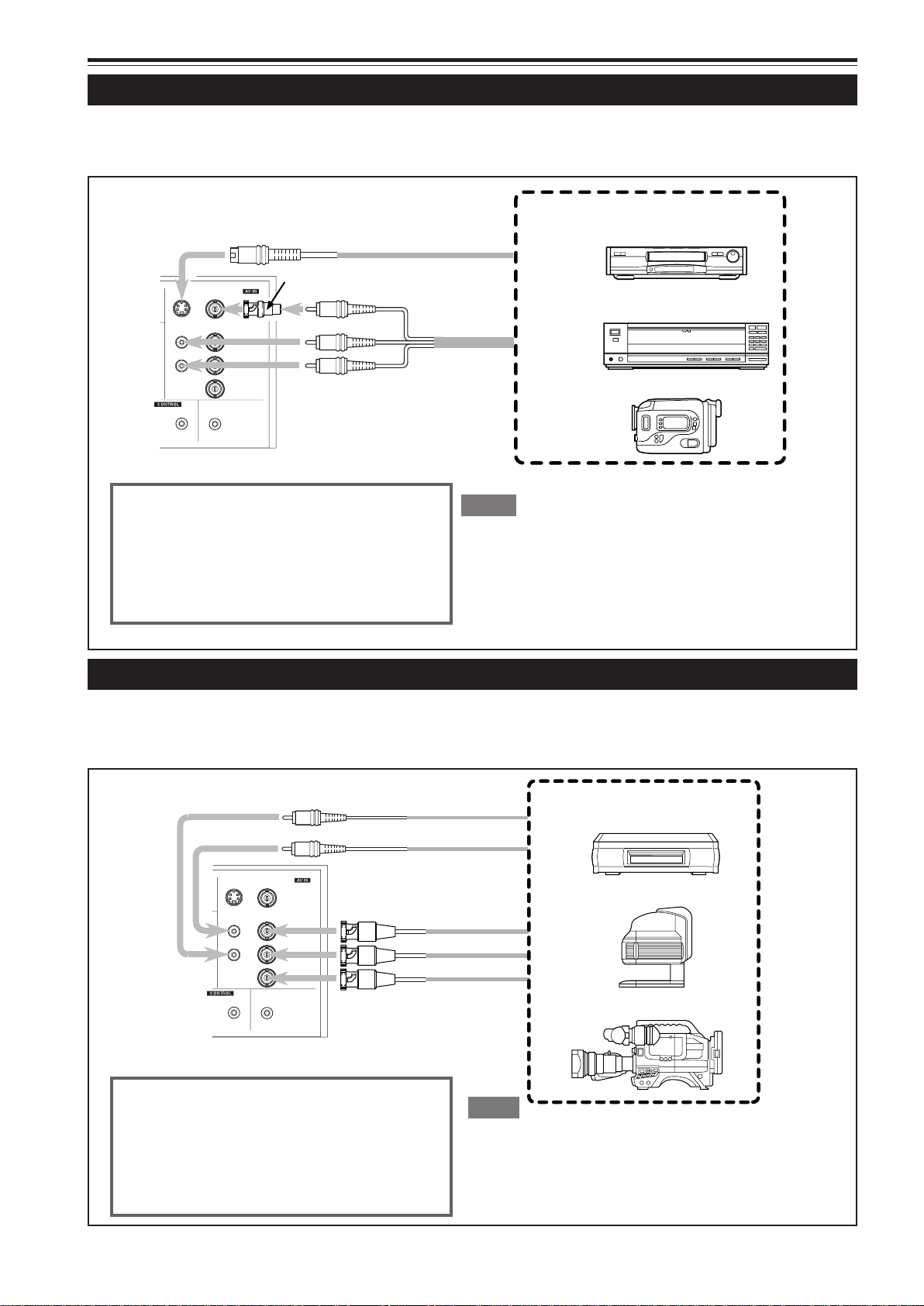
Connexions de divers appareils (suite)
Connexion à des appareils vidéo
Avant la connexion, assurez-vous de mettre hors tension le projecteur et l’appareil vidéo.
• Lisez attentivement le mode d’emploi fourni avec chaque appareil vidéo.
• Utilisez le câble de connexion audio/vidéo fourni. Le câble de connexion S-vidéo n’est pas fourni.
À Y/C
(vendu séparément)
Fiche de conversion BNC-RCA (fournie)
Câble S-vidéo
À VIDEO
À AUDIO (L)
À AUDIO (R)
Câble de
connexion
audio/vidéo
(fourni)
RS-232C
Y/C
AUDIO
REMOTE
VIDEO
Y
Y
L
R
/B-Y
P
B
/R-Y
P
R
AUDIO OUT
Pour choisir l’entrée audio correcte pour l’entrée
vidéo
La prise d’entrée vidéo (prise d’entrée AV IN) peut
être choisie avec la touche VIDEO. Cependant,
comme ce projecteur ne possède qu’une prise
d’entrée audio, reconnectez l’entrée audio en
fonction de l’appareil audio/vidéo utilisé.
Appareils vidéo
• Magnétoscope
• Lecteur de disque laser
• Camescope
Mémo
• Lors de la connexion d’un appareil vidéo, utilisez un correcteur de
base de temps (TBC) ou un appareil avec un tel correcteur intégré.
• Utiliser un câble prolongateur pour connecter l’appareil vidéo et le
projecteur peut causer une dégradation de l’image vidéo.
• Quand un signal avec beaucoup de sautillements est reproduit sur un
magnétoscope ou quand une lecture avec effets spéciaux est réalisée,
la partie supérieure de l’image ou l’image elle-même peut être effacée
ou déformée.
Connexion à des appareils “Hi-Vision”
Avant la connexion, assurez-vous de mettre hors tension le projecteur et les appareils “Hi-Vision”.
• Lisez attentivement le mode d’emploi fourni avec chaque appareil “Hi-Vision”.
• Utilisez des câbles BNC vendus séparément et des câbles audio pour connecter les appareils “Hi-Vision”.
À AUDIO (R)
À AUDIO (L)
Câble audio
RS-232C
Y/C
AUDIO
REMOTE
L
R
VIDEO
AUDIO OUT
Y
Y
/B-Y
P
B
/R-Y
P
R
(vendu séparément)
À VIDEO
À Y
À PB/B-Y
À PR/R-Y
Câble BNC (Vendu séparément)
Pour choisir l’entrée audio correcte pour l’entrée
vidéo
La prise d’entrée vidéo (prise d’entrée AV IN) peut
être choisie avec la touche VIDEO. Cependant,
comme ce projecteur ne possède qu’une prise
d’entrée audio, reconnectez l’entrée audio en
fonction de l’appareil audio/vidéo utilisé.
Mémo
• Les autres appareils avec des prises de sortie de signaux en
composante (lecteur de DVD (NTSC), etc.) peuvent être connectés.
*DVD: Digital Video Disc (Disque vidéo numérique)
• Les signaux au format-DTV (480i, 480p, 720p, 1080i) peuvent être
entrés. Pour les signaux au format-DTV pouvant être traités, référzvous à la page 69.
Appareils “Hi-Vision”
• Magnétoscope W-VHS
• Caméra Texte/vidéo
• Caméra vidéo “Hi-Vision”
20
Page 94

Connexions de divers appareils (suite)
Connexion d’autres appareils
Avant la conne xion, assurez-v ous de mettre hors tension le pr ojecteur et les autres appareils à connecter.
• Lisez attentivement le mode d’emploi fourni avec chaque appareil connecté.
• Des enceintes avec un amplificateur intégré et des consoles de jeux peuvent être connectées. Utilisez le câble de connexion
audio/vidéo et le câble audio fourni, ou le câble fourni avec la console de jeux.
RS-232C
Y/C
AUDIO
REMOTE
VIDEO
L
R
AUDIO OUT
Fiche de conversion BNC-RCA (fournie)
À VIDEO
À AUDIO (L)
Y
Y
/B-Y
P
B
/R-Y
P
R
À AUDIO (R)
Câble fourni avec la console de
jeux, ou câble de connexion audio/
vidéo fourni
À AUDIO OUT
• Enceintes avec amplificateur intégré
• Console de jeux, etc.
Câble audio (fourni)
(ou mini fiche stéréo)
Connexion à des appareils qui commandent le projecteur
Avant la connexion, assurez vous de mettre hors tension le projecteur et les appareils à connecter.
• Lisez attentivement le mode d’emploi fourni avec chaque appareil connecté.
• En connectant un ordinateur à la prise RS-232C, vous pouvez commander le projecteur. Vous pouvez aussi réaliser une
extension du capteur de télécommande infrarouge et la connecter à la prise REMOTE du projecteur.
* Des câbles de connexion sont nécessaires.
* Pour plus de détails, consultez un revendeur autorisé ou un centre de service.
• Ordinateur de
bureau
• Ordinateur portable
À la prise RS-232C
À la prise RS-232C
Câble de connexion inversée
RS-232C (vendu séparément)
À la prise RS-232C
Module d’extension
du capteur de
télécommande
infrarouge
(Doit être fabriqué)
AUDIO
PC
AUDIO
R
G
B
COMPUTER
OUT
À la prise REMOTE
H/Cs
V
RS-232C
Y/C
AUDIO
L
R
REMOTE
FRANÇAIS
21
Page 95

Connexions de divers appareils (suite)
Connexion à des ordinateurs
Avant la connexion, assurez-vous de mettre hors tension le projecteur et les ordinateurs.
• Lisez attentivement le mode d’emploi fourni avec chaque appareil.
■ Connexion à un ordinateur IBM PC ou compatible
• Utilisez le câble de connexion d’ordinateur fourni. Préparez aussi les câbles nécessaires pour la connexion des appareils.
• Ordinateur de
bureau
À le terminal du moniteur
• Ordinateur portatif
* Il y certains types d’ordinateur portatifs qui ne permettent pas à
l’écran LCD de fonctionner si un affichage extérieur est connecté.
Avec ce type d’ordinateur portatif, la sortie de l’affichage LCD et
de l’affichage extérieur doit être commutée.
Lors de la connexion d’une prise de sortie audio telle que la source
sonore de l’ordinateur, connectez la prise AUDIO en utilisant le câble
audio fourni.
Câble de connexion à
l’ordinateur (fourni)
À R
À G
À B
À COMPUTER IN-2
À COMPUTER IN-1
COMPUTER
À COMPUTER OUT
H/Cs
V
RS-232C
Y/C
AUDIO
L
R
REMOTE
À H/Cs
AUDIO
PC
AUDIO
R
G
B
OUT
À V
• Ordinateur de
bureau
• Appareils à sortie RVB
Lecteur de disque laser, etc.
À le terminal du moniteur
Câble non-fourni
(vendu séparément)
À R
À G
À B
À H/Cs
À V
Câble fourni avec le
moniteur (ou vendu
séparément) (D-sub,
15 broches sur 3
rangées)
POWER
Moniteur
* Quand un moniteur est connecté à la
prise COMPUTER OUT, vous pouvez
voir l’image vidéo de l’ordinateur sur le
moniteur.
22
Page 96

Connexions de divers appareils (suite)
Connexion à des ordinateurs (suite)
Avant la connexion, assurez-vous de mettre hors tension le projecteur et les ordinateurs.
• Lisez attentivement le mode d’emploi fourni avec chaque appareil.
■ Connexion à un Macintosh
• Utilisez le câble de connexion d’ordinateur fourni et l’adaptateur de conversion pour Mac fourni.
• Lors de la connexion d’une prise de sortie audio telle que la source
sonore de l’ordinateur, connectez la prise AUDIO en utilisant le câble
audio fourni.
• Ordinateur de bureau
• Les autres connections sont les mêmes que pour l’exemple de
connexion pour les ordinateurs IBM PC ou compatibles.
À la prise du moniteur
Adaptateur de conversion pour Mac
(fourni)
Câble de connexion d’ordinateur
(fourni)
À COMPUTER IN-1
PC
R
G
B
COMPUTER
OUT
AUDIO
AUDIO
H/Cs
V
RS-232C
Y/C
AUDIO
L
R
REMOTE
23
FRANÇAIS
Page 97

Connexions de divers appareils (suite)
Connexion du cordon d’alimentation (fourni)
Après que tous les appareils ont été connectés, connectez le cordon d’alimentation du projecteur. Ne le mettez pas encore
sous tension à l’aide de l’interrupteur MAIN POWER.
Y
C
N
P
E
G
M
E
R
T
E
P
M
M
E
LA
TE
A
R
E
P
O
Y
B
D
N
A
T
S
1 Insérez le cordon d’alimentation
dans la prise d’entrée secteur (AC
IN
~) du projecteur.
AC IN ~
1
Cordon d’alimentation (fourni)
2
ATTENTION
Pour éviter les incendies et les électrocutions, respectez
ce qui suit:
• Lorsque vous n’utilisez pas les appareils, débranchez leurs
cordons d’alimentation des prises secteur murales.
• Ne connectez pas les appareils en utilisant des cordons
d’alimentation autres que les cordons fournis.
• N’utilisez pas une tension différente de la tension indiquée.
• Ne coupez pas, n’endommagez pas ni ne modifiez les
cordons d’alimentation. Ne mettez pas d’objets lourds dessus,
ne chauffez pas ni ne tirez sur les cordons d’alimentation,
car ils seraient endommagés.
• Ne branchez ni ne débranchez les fiches avec les mains
mouillées.
2 Insérez la fiche du cordon d’ali-
mentation fourni sur une prise
secteur murale.
ATTENTION
• Comme le courant nécessaire pour le projecteur est élevé,
insérez la fiche d’alimentation directement dans la prise
secteur murale.
24
Capuchon
d’objectif
Y
■Pour utiliser le projecteur
C
N
P
E
G
M
E
R
T
E
P
M
M
E
A
L
E
T
A
R
E
P
O
Y
B
D
N
A
T
S
• Retirez le capuchon d’objectif.
* Le capuchon d’objectif a un fil qui lui est attaché et qui
est fixé au projecteur.
N’oubliez pas de remettre le capuchon en place quand
vous n’utilisez pas le projecteur.
Page 98

Connexions de divers appareils (suite)
Mise sous tension des appareils connectés au projecteur
Mettez sous tension le projecteur et les appareils connectés dans l’ordre suivant.
Sautez les appareils non-connectés, s’il y en a.
Mettez sous tension le moniteur de l’ordinateur envoyant un signal au projecteur
▼
Les périphériques de l’ordinateur envoyant un signal au projecteur
(Disque dur, disque magnéto-optique, scanner, etc.)
▼
Mettez sous tension les appareils audio/vidéo envoyant un signal au projecteur
▼
Le projecteur lui-même
▼
Mettez sous tension les appareils à qui le projecteur envoie un signal
(Appareils audio/vidéo et moniteurs)
▼
Mettez sous tension l’ordinateur envoyant un signal au projecteur
* Pour mettre les appareils hors tension, utilisez l’ordre inverse.
Mémo
Si vous appuyez sur la touche OPERATE quand l’appareil n’est pas sous tension:
• Si le filtre ou le couvercle de remplacement de la lampe est mal placé, le projecteur ne se met pas sous tension. V érifiez qu’ils sont correctement
installés.
• Vous devez appuyer sur la touche OPERATE pendant au moins une seconde.
ATTENTION ET REMARQUES
Ne coupez pas brutalement l’alimentation avec l’interrupteur MAIN POWER quand le projecteur est utilisé ou
immédiatement après. Cela pourrait entraîner un mauvais fonctionnement.
•Comme le projecteur utilise une lampe à haute intensité qui est chauffée à haute température, les ventilateurs de refroidissement
fonctionnent même pendant la projection. De même, après l’utilisation, les ventilateurs de refroidissement continuent de
fonctionner quand la touche OPERATE est pressée, jusqu’à ce que la lampe source de lumière ait refroidie. Pendant le
refroidissement, l’indicateur STAND BY clignote pour avertir que les ventilateurs de refroidissement fonctionnent. Pendant
cette période de temps, ne mettez pas le projecteur hors tension. Une fois que le refroidissement de la lampe source de
lumière est terminé (les ventilateurs sont arrêtés) et que l’indicateur STAND BY s’est allumé, mettez le projecteur hors tension.
•Si vous appuyez sur la touche OPERATE immédiatement après que la lampe source de lumière s’est allumée, il faudra environ 40
secondes avant que la lampe s’éteigne. Pour rallumer la lampe, attendez 10 secondes ou plus avant d’appuyer sur la touche OPERATE.
Si l’indicateur TEMP s’allume, l’alimentation est coupée automatiquement.
•Pendant que la lampe source de lumière est allumée, si une température anormalement élevée est détectée, l’indicateur
TEMP s’allume, l’alimentation est coupée automatiquement et l’indicateur EMERGENCY clignote (mode d’urgence).
Quand l’indicateur EMERGENCY clignote, mettez le projecteur hors tension après que les ventilateurs de refroidissement
ont arrêté de fonctionner.
•Si les anomalies suivantes se produisent, le projecteur entre en mode d’urgence (l’indicateur EMERGENCY clignote).
Quand le projecteur entre en mode d’urgence, il arrête la projection automatiquement et laisse fonctionner les ventilateurs
pendant environ 20 secondes.
– Quand le filtre est mal placé.
– Quand le filtre est sale.
– Quand la lampe source de lumière s’éteint soudainement.
– Quand les ventilateurs s’arrêtent.
– Quand la température intérieure s’élève anormalement.
– Quand l’alimentation secteur est coupée brusquement ou interrompue.
•Quand le projecteur entre en mode d’urgence:
Après que les ventilateurs se sont arrêtés, mettez l’appareil hors tension et débranchez le cordon d’alimentation. Rebranchez
ensuite le cordon d’alimentation et essayez de faire fonctionner le projecteur. S’il retourne en mode d’urgence, mettez-le hors
tension après que les ventilateurs se sont arrêtés, débranchez le cordon d’alimentation et consultez un revendeur autorisé ou
un centre de service pour le faire réparer.
25
FRANÇAIS
Page 99

Fonctionnement de base
OPERATE
■ Touches du projecteur
STAND BY
LAMP
TEMP
EMERGENCY
VIDEO
COMPUTER
SETTING
3
+
QUICK
ALIGN.
2
-
CY
EN
P
RG
EM
T
P
ME
M
E
A
L
TE
A
ER
OP
Y
B
D
AN
T
S
Indicateur STAND BY
Indicateur OPERATE
Touche OPERATE
2, 1
Interrupteur MAIN POWER
1, 2
Ce qui suit décrit la procédure de base pour l’utilisation normale
du projecteur.
1. Mise sous tension
1 Mettez l’interrupteur MAIN
POWER sur la position ON [ ❙ ].
ON [ ❙ ]:L’appareil est mis sous tension et l’indicateur
STAND BY s’allume.
Indicateur du projecteur
STAND BY
(Allum)
2 Appuyez sur la touche OPERATE
pendant plus d´une seconde.
• L’indicateur OPERATE s’allume.
• Environ 30 secondes après que l’appareil a été mis sous
tension à l’aide de l’interrupteur MAIN POWER vous
pouvez commencer la projection.
Télécommande
ou
Projecteur
(Allumé)
OPERATE
■ Télécommande
OPERATE
VOL.
PAGE
BACK
PRESET
QUICK
ALIGN.
COMPUTER VIDEO
T
FOCUS
ZOOM
W
MENU/ENTER
MUTING
Remarques
• Après la mise sous tension, l’écran peut apparaître brouillé pendant
quelques secondes, mais ce n’est pas un mauvais fonctionnement.
• Si lampe source de lumiére ne s’allume pas, essayez d’appuyer
une seconde fois ou plus sur la touche OPERATE.
■ Mise hors tension
1 Appuyez sur la touche OPERATE
pendant plus d´une seconde.
• L’indicateur STAND BY clignote et le projecteur entre
en mode de refroidissement.
Touche OPERATE
2, 1
Exemple de touche du projecteur
(Allumé)
OPERATE
\
Projecteur
(Clignote)
STAND BY
2 Mettez l’interrupteur MAIN
PO WER sur la position OFF [
‡‡
‡]
‡‡
après que l’indicateur STAND BY
s’est allumé d’une façon
constante.
‡‡
OFF [
‡]: L’appareil est mis hors tension et l’indicateur
‡‡
AV
ST AND BY s’éteint.
Projecteur
(éteint)
STAND BY
* Ne mettez pas l’appareil hors tension pendant le mode
de refroidissement (l’indicateur STAND BY clignote).
Mettez-le hors tension après que l’indicateur STAND
BY s’est allumé de façon constante (mode d’attente).
26
Page 100

Fonctionnement de base (suite)
COMPUTER VIDEO
■ Touches du projecteur
STAND BY
LAMP
TEMP
EMERGENCY
VIDEO
COMPUTER
SETTING
3
+
QUICK
ALIGN.
2
-
■ Télécommande
OPERATE
VOL.
PAGE
BACK
PRESET
COMPUTER VIDEO
T
FOCUS
ZOOM
W
MENU/ENTER
Touche VIDEO
Touche COMPUTER
Touche COMPUTER
Touche VIDEO
Touches ZOOM (T/W)
2.
Sélection de l’entrée vidéo à projeter
■ Appuyez sur la touche VIDEO ou sur la touche
COMPUTER pour choisir l’entrée.
• Chaque fois que vous appuyez sur la touche, l’entrée choisie
change comme suit.
■ Quand vous appuyez sur VIDEO:
Y/C
VIDEO
■ Quand vous appuyez sur COMPUTER:
COMP1
COMPUTER 1
Télécommande Projecteur
Affichage sur l’écran
Ligne
CH: 1
YPBPR NTSC(480i)
* Quand l’entrée est commutée, l’affichage de la ligne (ex.
YPBPR) et l’affichage de la source (ex. NTSC(480i)) sont
montrés sur la partie supérieure de l’écran (ils disparaissent
au bout de 5 secondes). Cependant, ils n’apparaissent pas si
AFF SOURCE (affichage source) dans “réglage et ajustement
des autres fonctions (OPTIONS)” à la page 44 est réglé sur
OFF. (Pour régler la source, voir page 47.)
Par ailleurs, après réglage d’un canal, le nom de ce dernier
apparaît dans le coin supérieur droit de l’écran. (Pour le
réglage des canaux, Voir les pages 31, 49 et 54.)
Remarque
• Pour choisir l’entrée audio correcte pour l’entrée vidéo
La prise d’entrée vidéo (prise d’entrée AV IN) peut être changée avec la
touche VIDEO. Cependant, comme ce projecteur n’a qu’une prise d’entrée
audio, reconnectez l’entrée audio en fonction de l’appareil audio/vidéo utilisé.
YPBPR
COMP2
COMPUTER 2
VIDEO
COMPUTER
Canaux
Source
QUICK
ALIGN.
AV
MUTING
ATTENTION
• NE FRAPPEZ PAS ce projecteur pendant qu’il
fonctionne; sinon, la lampe source de lumière risquerait
de s’éteindre (l’indicateur EMERGENCY s’allume).
Si le choc éteint la lampe source de lumière —
Mettez l’appareil hors tension en appuyant sur
l’interrupteur MAIN POWER, puis mettez-le à nouveau
sous tension. Vous pouvez à présent utiliser le
projecteur comme d’habitude.
3. Ajustement de la taille de l’écran
■ Ajustez la taille de l’écran avec les touches ZOOM (T/
W) de la télécommande.
■ Pour augmenter la taille de l’écran:
Appuyez sur la touche ZOOM (W).
■ Pour diminuer la taille de l’écran:
Appuyez sur la touche ZOOM (T).
Télécommande
T
ZOOM
W
Remarque
• L’ajustement de la taille de l’écran (ajustement du zoom) peut aussi être fait
à partir du menu de réglage.
Pour l’utilisation du menu de réglage, référez-vous à “Réglages de base” à
la page 32.
27
FRANÇAIS
 Loading...