

Page 1
SERVICE MANUAL
D-ILA PROJECTOR
PA02020051
DLA-HX2U, DLA-HX2E
¨
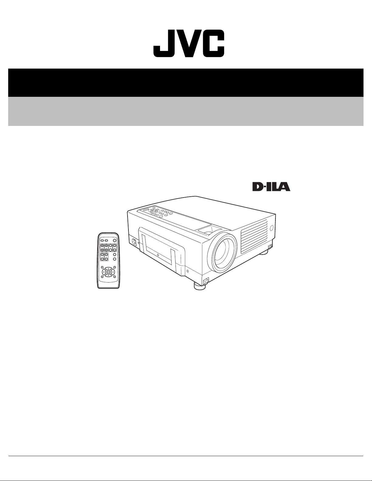
OPERATE
PC VIDEO
W
DIGITAL
V-KEYSTONE H-KEYSTONE
SCREEN
ZOOM
S
FREEZE
VOLUME
FOCUS
QUICK ALIGN.
MENU EXIT
ENTER
PRESET HIDE
Regarding service information other than these sections, refer to the service manual No. PA018 (DLA-HX1U, DLA-HX1E).
Also, be sure to note important safety precautions provided in the service manual.
TABLE OF CONTENTS
1 PRECAUTION. . . . . . . . . . . . . . . . . . . . . . . . . . . . . . . . . . . . . . . . . . . . . . . . . . . . . . . . . . . . . . . . . . . . . . . . . 1-3
2 SPECIFIC SERVICE INSTRUCTIONS . . . . . . . . . . . . . . . . . . . . . . . . . . . . . . . . . . . . . . . . . . . . . . . . . . . . . . 1-3
3 DISASSEMBLY . . . . . . . . . . . . . . . . . . . . . . . . . . . . . . . . . . . . . . . . . . . . . . . . . . . . . . . . . . . . . . . . . . . . . . . 1-5
4 ADJUSTMENT . . . . . . . . . . . . . . . . . . . . . . . . . . . . . . . . . . . . . . . . . . . . . . . . . . . . . . . . . . . . . . . . . . . . . . . . 1-5
5 TROUBLESHOOTING . . . . . . . . . . . . . . . . . . . . . . . . . . . . . . . . . . . . . . . . . . . . . . . . . . . . . . . . . . . . . . . . . 1-16
COPYRIGHT © 2005 Victor Company of Japan, Limited
No.PA020
2005/1
Page 2

SPECIFICATION
GENERAL
Type
Dimensions
(W × H ×D)
Mass
Power requirements
Power Consumption
Operating temperature
Operating humidity
Storage temperature
Projection angle
(Adjustable Foot)
Remote control unit RM-MSX21G
operation
Accessories Remote control unit (RM-MSX21) × 1
OPTIC
Projection system
D-ILA device
Projection lens 1.3times (2.1 : 1-2.6 : 1) manual ZOOM
Screen size 37" (94.3cm) [tele : min]-275" (698.5cm)
Projection distance Tele side :
Light lamp BHL5006-S
ELECTRIC
Color system NTSC3.58 / NTSC4.43 / PAL / SECAM
Resolution 1400 × 788 dots (during RGB input)
Scanning frequency Horizontal : 15kHz ~ 120kHz
Keystone distortion
correction
D-ILA PROJECTOR
Approx. 298 mm × 134 mm × 360 mm
(Approx. 11-7/10" × 5-3/10" × 14-1/5")
(Excluding handle, lens and protrusions)
Approx. 6.0kg (Approx.13.2lbs.)
AC 100-240V 50Hz/60Hz
3.4A (100VAC)~1.42A (240VAC)
+5°~+35°[41°F~95°F]
20%~80% (no-condensation)
-10°C~+60°C[14°F~140°F]
Vertical : max. +6° upper
Distance : 7m
Angle: Horizontal =±30° Vertical =±20°
Mass
100g (includes dry cell battery)
Dry cell battery (size : AA/R6) × 2
AV connection cable (2m) × 1
SCREEN TRIGGER terminal cable (1.8m)
Power code × 1
D-ILA(reflective-type active-matrix)system
0.64-inch(1.64cm) measured diagonally
[H:1400 pixels × V:788 pixels] × 3
< Total : 3,309,600 pixels >
lens [50% fix shift]
< recommended >
*measured diagonally with aspect 16:9
approx 2m (6.56ft)-11.5m(37.82ft)
wide side :
approx 1.6m (5.26ft)-12m(39.37ft)
UHP(Ultra High-Pressue mercury) lamp
(Automatic switching / Manual switching)
1000TV line
(Horizontal resolution aspect ratio 4:3,
during video input)
Vertical : 24Hz,25Hz,30Hz,50Hz~120Hz
Top-bottom tilt:
Horizontal=about 30°, Vertical=about 10°
× 1
Audio power output 1w(8Ω) : monaural
Speakers 4cm[1-5/8"] 8Ω round type × 1
Fuse QMF51D2-6R3J1(6.3A)
OUTPUT TERMINAL
SCREEN TRIGGER 12V, 100mA DC Power Jack × 1
INPUT CONNECTORS
VIDEO IN VIDEO signal
Y / C Luminance/Chroma separate video
signal mini DIN 4-pin × 1
Y
1.0V(p-p) 75Ω
C
0.286V(p-p)(burst) 75Ω [NTSC]
0.3V(p-p)(burst) 75Ω [PAL]
VIDEO Composite video signal
RCA, jack × 1
1.0V(p-p) 75Ω sync.
PC1 Analog RGB signal
D-sub 15-pin × 1
PC2 Component (B-Y,R-Y,Y) signal /
DTV (Pb,Pr,Y) format signal /
Analog RGB signal /
External sync. signal
BNC connector × 5
·Cb(B-Y)·Cr(R-Y) Component (Color Difference signal)
Y
Y
1.0V(p-p) 75Ω negative sync.
Cb
0.7V(p-p) 75Ω negative sync
Cr
0.7V(p-p) 75Ω negative sync
Y . Pb . Pr DTV format signal
[480i / 480p / 720p / 1080i]
Y
1.0V(p-p) 75Ω negative sync. [480i / 480p]
1.0V(p-p) 75Ω 3-value sync [720p / 1080i]
Pb / Pr
PC3 Digital RGB signal
AUDIO AUDIO signal
CONTROL Using external computer control
RS-232C RS-232C protocol
REMOTE For connecting an external sensor
0.7V(p-p) 75Ω
DVI-D 24-pin × 1
R
±0.5V(p-p) 50 Ω
G
±0.5V(p-p) 50 Ω
B
±0.5V(p-p) 50 Ω (Include H/V sync)
CLK
±0.5V(p-p) 50 Ω
RCA pin jack × 1
0.5V(rms), high impedance
D-sub 9-pin × 2 (in / out)
Baud rate : 9600bps / 19200bps
Data length : 8 bits (no parity)
Stop bit : 1 bit
Flow control : none
Ø3.5mm stereo mini-jack × 1
1-2 (No.PA020)
Page 3
SECTION 1
PRECAUTION
Please refer to "DLA-HX1U, DLA-HX1E (No.PA018)" about this section.
SECTION 2
SPECIFIC SERVICE INSTRUCTIONS
Please refer to "DLA-HX1U,DLA-HX1E (No.PA018)" about this section except a written item.
2.1 SERVICE POLICY
The following service policy is being utilized.
Item
MAIN PWB ASS'Y SXZ-1006A SXZ-1009A Replace parts
DD SUB PWB ASS'Y SXZ-3002A ← Replace parts
POWER PWB ASS'Y SXZ-9001A ← Replace parts
TERMINAL PWB ASS'Y SXZ-0J003A SXZ-0J003B Replace parts
IR PWB ASS'Y SXZ-0R001A ← Replace parts
CONT. & 3.3V PWB ASS'Y SXG-0P002A ← Replace parts
OPTICAL BLOCK ASS'Y HX1OP-S HX2OP-S Replace (module)
LAMP BALLAST UNIT QAL0435-002 ← Replace (module)
LAMP UNIT BHL5006-S ← Replace (module)
NOTE:
Mark ← is same as left.
DLA-HX1U, DLA-HX1E DLA-HX2U, DLA-HX2E
Parts number Parts number
Service method
(No.PA020)1-3
Page 4
2.2 SERVICE MENU
2.2.1 Setting items
Item Initial value
Adjustment
range
Description
Software version
Software version ------ ------ Information of PROGRAM -----Cont. / Bright
Contrast
R / G / B / Main
Brightness
R / G / B
[Service adjust.
value]
[Service adjust.
value]
0 ~ 255 Main contrast adjustment. Common
0 ~ 255 Main brightness adjustment. Common
Cb / Cr 31 0 ~ 31 Component signal adjustment. AV system
Option
VGA mode* 480p [Select 2 items] Sets processing for VGA signal input (H : 31.5 kHz / V : 60 Hz).
[480p] : Process as 480p (video system) signal
[VGA] : Process as VGA (PC system) signal
Back color Blue [Select 2 items] "Sets no signal background color to blue or black.
[Blue] : Blue color [Black] :Black color"
Auto shutdown ON [Select 2 items] If POWER OFF is selected, no warning will be displayed on and after 1900
hours of the lamp operating time. However, POWER ON is also available
after 2000 hours of the lamp operating time.
Over scan* Over scan [Select 2 items] Sets scan size for video signal.
[Normal] : Under scan (100%) [Over scan] : Normal (95%)
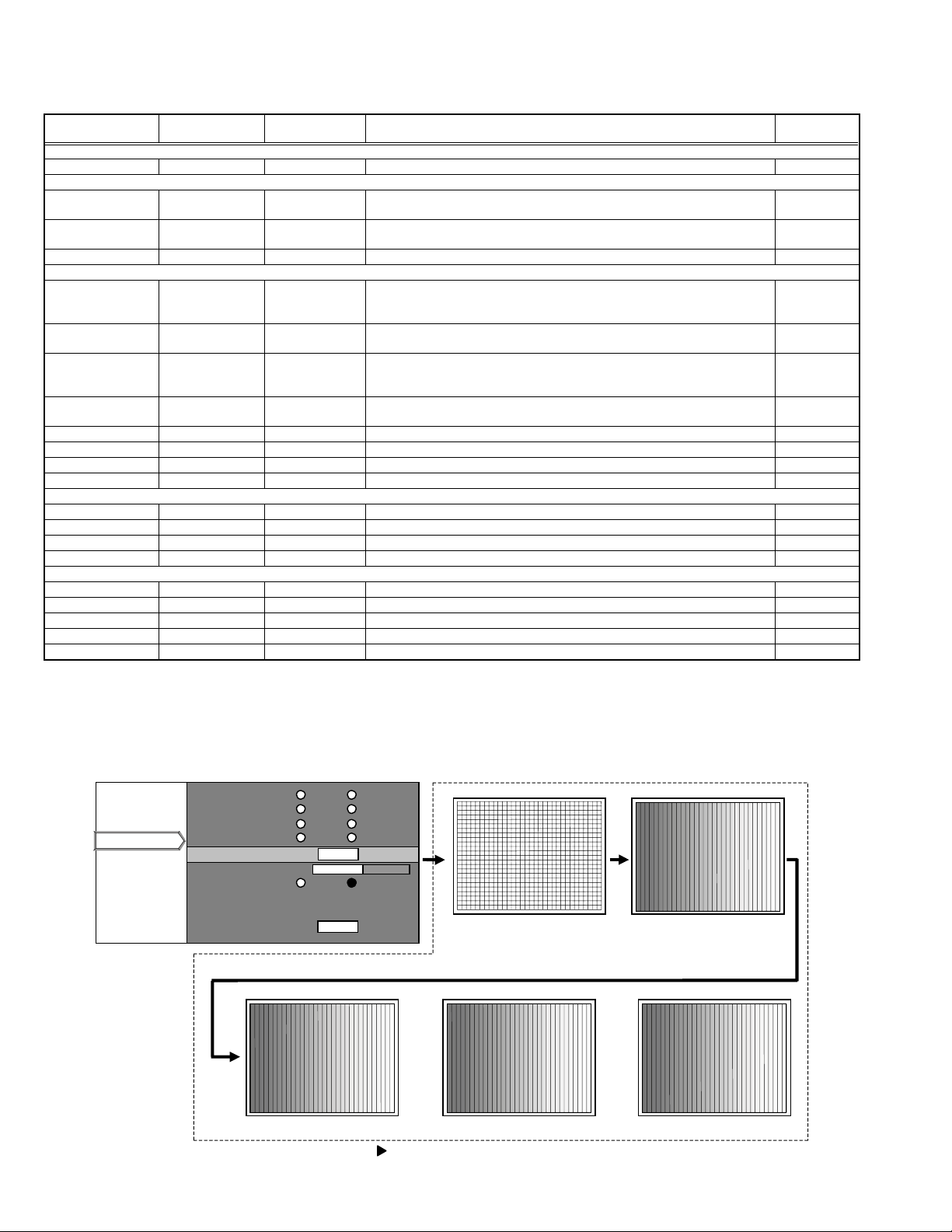
Test pattern ------ [Select 5 items] Press [ENTER] then Test pattern appear. (Refer to following Fig.1) Common
Sharpness 0 -3~3 Main sharpness adjustment. Common
PC2 set up 7.5IRE [Select 2 items] Setting of [0IRE] [7.5IRE] Common
All reset ------ ------ Press [ENTER] then all reset. Common
Color temp
Color temp User Select 3 items Setting of [6500] [Normal] [User] Common
R 0 -255~0 Setting color temp of red Common
G 0 -255~0 Setting color temp of green Common
B 0 -255~0 Setting color temp of blue Common
Resolution
Horizontal resolution
Vertical resolution
Tracking
Position of Horizontal display
Position of Vertical display
Depending on signals
Depending on signals
Depending on signals
Depending on signals
Depending on signals
← Set the horizontal resolution
← Set the vertical resolution
← Same as for the tacking in the User Menu
← Same as for the display of the horizontal position in the User Menu
← Same as for the display of the vertical position in the User Menu
Setting
object
Each signal
(VGA)
Common
Common
Each signal
(AV system)
Analog PC signal
Analog PC signal
Analog PC signal
Analog PC signal
Analog PC signal
∗ : When these items are set, the service menu is automatically closed.
Notice on items in relation to resolution
(1) These functions may sometimes not project some types of signals properly.
(2) These functions cannot set resolution of signals that are input from DVI terminal and video signals (displayed in video menu).
(3) Method of changing the resolution (See the next page.)
Test patter Screen
Software version
Cont. / Bright
Option
Option
Color temp
SERVICE MENU Screen
VGA mode 480p VGA
B
ack color Bl ue Black
Auto shutdown ON OFF
Over scan Normal Over sca n
Test pattern
Test pattern
harp ness 0
S
PC2 set up 0IRE 7.5IRE
ENTER
1-4 (No.PA020)
All reset
ENTER
Red Green Blue
(When the key is pressed, the screen is changed one after the other as shown in the above.)
cross-hatch Gray scale
Page 5
SECTION 3
DISASSEMBLY
Please refer to "DLA-HX1U, DLA-HX1E (No.PA018)" about this section.
SECTION 4
ADJUSTMENT
4.1 BEFORE STARTING ADJUSTMENT
(1) Adjustment items utilize a personal computer.
This instruction is for HX2 PSA CONTROL PROGRAM
Program. Use the latest version program.
(2) Data back up is required before adjustments.
(3) Allow the equipment and test instruments adequate time
(at least 30 minutes) to warm-up.
(4) Confirm the set is properly connected to the specified AC
power source.
(5) Use care not to disturb internal controls and parts not spe-
cifically mentioned.
(6) Unless specifically mentioned in the "ADJUSTMENT PRO-
CEDURE" steps, do not change any data.
4.2 INSTRUMENTS AND TOOLS
• Oscilloscope
• PAL signal generator : composite output, Y/C output
Gray scale : 0IRE-100IRE
Color bar : include 75% white peak
• NTSC signal generator : composite output [Y / CB / CR]
Flat (raster) pattern : 25%
• HDTV signal generator : composite output [Y / PB / PR]
Flat (raster) pattern : 25%
• PC signal generator
Signal : VGA / SXGA
Gray scale : 0.7V (p-p) [include 100% White / 0% Black]
∗Show at least 2 images on 1 screen (Upper scale and Lower
scale must be reversed)
Cross-hatch
Flat (raster) pattern : 100%, 93%, 13%, 0%
• Light meter [for example: Minolta T-10]
• Color-meter [CL-200]
• Remote control unit [RM-MSX21G]
• Personal computer
Operating system Windows 98 ME 2000 XP
Memory More than 16 Mbytes
Hard disk free space More than 5 Mbytes
RS-232C interface At least 1 port
Display resolution Minimum : 800 × 600 pixels
Recommended : 1024 × 768 pixels or better
Display colors Minimum : 8 bits/pixel
Recommended : 16 bits/pixel or better
Input devices Keyboard and mouse
• Adjustment software : HX2 PSA CONTROL PROGRAM
• RS-232C 9pin NULL-MODEM (cross) cable
• Photoelectric conversion device (one of these)
Light meter [Minolta T-10] A-out (Analog output)
Photoelectric conversion device (for example: HAMAMAT-
SU PHOTONICS S1226-8BK)
Phototransistor or CdS photoconductor with amplifier
• Color filters
G color filter (ex. MELLES GRIOT 03 FIV 044)
R color filter (ex. MELLES GRIOT 03 FIB 014)
B color filter (ex. MELLES GRIOT 03 FIV 028)
• Screen
• Darkroom (illumination less than 0.03 lx)
(No.PA020)1-5
Page 6
4.3 REQUIRED ADJUSTMENTS BY REPLACING COMPONENTS
The following adjustment procedure is required after replacing PWB ASS'Ys, LAMP BALLAST UNIT and OPTICAL BLOCK.
Items noted as "Check" means check the condition, then adjust if required.
4.3.1 Component required adjustment at replacing
Adjustment items MAIN TERMINAL DD SUB POWER
1. D-ILA COMMON DC Check Required Check Check Required
2. GAMMA (GRADATION / WHITE BALANCE) Check Required Check Check Required
3. GAMMA (D65) Check Required Check Check Required
4. SHADING (UNIFORMITY) Check Check Check Required
5. 8 - PHASE VERTICAL BARS Check Required Required
6. A-D CONVERTER APERTURE Required
7. COLOR PROFILE Check Required
8. GHOST Check Required
9. FRAME Check Required
4.3.2 List of required instruments and tools (except those related to the personal computer)
LAMP
BALLAST
OPTICAL
BLOCK
Adjustment items
1. D-ILA COMMON DC Required (Required)
2. GAMMA (
3. GAMMA (D65) Required Required Required Required
4. SHADING (UNIFORMITY) Required Required Required
5. 8 - PHASE VERTICAL BARS Required Required
6. A-D CONVERTER APERTURE Required Required Required
7. COLOR PROFILE Required Required
8. GHOST Required
9. FRAME Required
4.3.3 Data backup
Before replacing major components such as PWB ASS'Ys, UNIT or BLOCK, be sure to backup the data contained in the set.
In absence of data backup, complete adjustment becomes necessary.
z PREPARATION
(1) Make sure that Version.ini file is located in the same folder of the PSA controller.
(2) Remove all signal cables except for the interface cable to the PC from the main body.
z DATA SAVE
(1) Enter Stand-by mode and open the PSA controller on the PC.
(2) Click [System] in the main menu. When the pull down menu is displayed, click [Backup ROM Data] and open ROM Data Up
(3) Tick [Main EEPROM] and [Sub EEPROM] in [Target EEPROM].
(4) When [Down Load] is selected, data will be downloaded in the order of EEPROM → EEPROM2 → SUB EEPROM.
(5) When the download has completed, Save Data with File Name dialog box will be displayed. Then save the data with a file
z DATA ENTRY
(1) Enter Stand-by mode and open the PSA controller on the PC.
(2) Click [System] in the main menu. When the pull down menu is displayed, click [Backup ROM Data] and open ROM Data Up
(3) Tick [Main EEPROM] in [Target EEPROM].
(4) When [Down Load] is selected, Open dialog box will be displayed. Then select a file which you want to upload.
(5) The data will be downloaded in the order of EEPROM → EEPROM2 → SUB EEPROM.
GRADATION / WHITE BALANCE
Load/Down
Load.
name.
Load/Down Load.
OSCILLOSCOPE
) Required Required Required Required
PC signal
generator
NTSC
signal
generator
HDTV
signal
generator
Light meter Color filter Color meter
1-6 (No.PA020)
Page 7

4.4 ADJUSTMENT PROCEDURE
4.4.1 D-ILA COMMON DC adjustment
Instruments REPLACING COMPONENTS
Test point
Adjustment menu < DDIC >
Preparation Running the unit enough before adjustment
Note :
Large deviation of this adjustment can cause image flicker.
Residual image or element burn can occur when out of adjustment.
WATCHING ADJUSTMENT
(1) Open Menu [DDIC] [Flat Field / DD Ctrl], and set [Dual Scan] to [Off].
(2) Set [R Mute], [G Mute] and [B Mute] to [On].
(3) Set [R] Flat Field level to 512, and set [G] and [B] Flat Field level to 0.
(4) Open Menu [DDIC] [EVR], then adjust [R Com] to minimize the flickers with watching. If there is unevenness with the flickers,
try to manage the balance of flickers by reducing the high-visibility portions of the flickers as much as possible.
Note :
Do not adjust under the lamp have flickers.
(5) Open Menu [DDIC] [Flat Field / DD Ctrl], and set block [R] Flat Field level to 0.
(6) Set [G] Flat Field level to 512.
(7) Open Menu [DDIC] [EVR], then adjust [G Com] to minimize the flickers with watching. If there is unevenness with the flickers,
try to manage the balance of flickers by reducing the high-visibility portions of the flickers as much as possible.
(8) Open Menu [DDIC] [Flat Field / DD Ctrl], and set block [G] Flat Field level to 0.
(9) Set [B] Flat Field level to 512.
(10) Open Menu [DDIC] [EVR], then adjust [B Com] to minimize the flickers with watching. If there is unevenness with the flickers,
try to manage the balance of flickers by reducing the high-visibility portions of the flickers as much as possible.
(11) Open Menu [DDIC] [Flat Field / DD Ctrl], and set block [B] Flat Field level to 0.
(12) When all of the adjustments are finished, set [R Mute] [G Mute] [B Mute] to [Off].
(13) Set [Dual Scan] to [On].
z DD SUB PWB ASS'Y
z OPTICAL BLOCK
(No.PA020)1-7
Page 8

4.4.2 GAMMA (High) adjustment
Instruments SVGA signal generator [Gray scale]
Light-meter
Color-meter (CL-200)
Color filter (R / G / B)
Test point
Adjustment menu < DDIC > < Gamma >
Preparation Completed D-ILA COMMON DC adjustment
PREPARATION
(1) Set to ZOOM at Wide end, if a zoom lens is installed.
(2) Measure the lightness in room with a calibrated light-meter and set the lightness to below 0.03lx.
(3) Set the light-meter on the center of image.
(The distance from the projection lens to the light-meter is approximate 30cm, then don't move them.)
(4) Open menu [Gamma] and click [GAMMA#1] then click [GAMMA#2].
(5) Open Menu [Gamma] and click [Default], then make sure that the Gamma line is linear. After a check, click the [Transmit] and
transmit data.
(6) Open Menu [DDIC] and set [LUMDAT] to [Off].
(7) Open Menu [DDIC] [Flat Field / DD Ctrl], and set [R Mute], [G Mute] and [B Mute] to [On].
(8) Allow the unit adequate time (more than 10 minutes) to warm-up.
(9) After installing the top cover, adjust the unit.
(10) Set OSD Color Temp to High.
OFFSET GAIN ADJUSTMENT
(1) Set the G color filter in front of the light-meter, and measure the luminance of the center of the screen.
(2) Open [DDIC] [EVR] menu and set [R OFFSET] and [B OFFSET] to 255. (Record the data before adjustment. In the Menu, the
OFFSET adjusted color should be kept in adjustment ready state.
(3) Open Menu [DDIC] [Flat Field / DD Ctrl] and set [R], [G] and [B] Flat Field level to 0 similarly.
(4) Open Menu [DDIC] [EVR] and set [G OFFSET] to 255, then record the illumination intensity (the lowest illumination intensity)
at this time.
(5) Open Menu [DDIC] [Flat Field / DD Ctrl], and set [G] Flat Field level to 1023.
(6) Open Menu [DDIC] [EVR], and adjust [G OFFSET] so that the illumination intensity becomes the highest. Record the illumi-
nation intensity (the highest illumination intensity) at this time.
(7) The target of the 0 IRE adjustments should be the higher illumination intensity between the value 1 (1.05 times of the lowest
illumination intensity) and the value 2 (the highest illumination intensity × 0.95 / 1000).
(8) Open Menu [DDIC] [Flat Field / DD Ctrl], and set the Flat Field level of [G] to 64. Under this condition, open Menu [DDIC] [EVR]
and adjust [G OFFSET] so that the illumination intensity falls within the target value of the 0 IRE adjustments in 7) above.
(9) Open Menu [DDIC] [Flat Field / DD Ctrl],and set the Flat Field level of [G] to 960. At this time, click [Gain/Setup] of [Gain] and
adjust the illumination intensity with the cursor so that it becomes 95% of the highest illumination intensity.
(10) Repeat the adjustment so that the requirements in step 8) and 9) are met together.
(11) Adjust [R], [B] in the same way with [R], [B] color filter.
(12) Open Menu [DDIC] [Flat Field / DD Ctrl], and set the Flat Field level of [R], [G] and [B] to 960, respectively. Then measure the
uv value using a color-meter. If the uv value exceeds +0.025, open [Gain/Setup] and lower the [Gain] value so that the
uv value falls within +0.025. In case where the uv value is less than +0.025, no adjustment is required. (By clicking [ALL],
adjust the eight phases together.
GAMMA & COMPUTATION OF ADJUSTMENT TARGET LUMINANCE
(1) Open Menu [Gamma] and set the control point to [VGP].
(2) Put [G] color filter in front of the light-meter and measure the illumination intensity at the center of the screen.
(3) Open Menu [DDIC] [Flat Field / DD Ctrl], and adjust the Flat field level of [G] to 960, [R] and [B] to 0. Then measure the 100
IRE illumination intensity of [G].
(4) Based on the calculating table for target illumination intensity and the measurement results obtained in 3) above, calculate the
target illumination intensity of the control points 14-2.
(5) By adjusting the Flat Field level of each control point, adjust the illumination intensity of the screen so that it falls within the
values calculated in accordance with the calculating table.
(6) If the Gamma curve for the adjusting points 2 and 3 are found irregular in form, or the target lightness cannot be set, adjust
the illumination intensity so that visually smoothed curves are obtained.
REPLACING COMPONENTS
z DD SUB PWB ASS'Y
z OPTICAL BLOCK
1-8 (No.PA020)
Page 9

< ADJUSTMENT TARGET ILLUMINATION TABLE >
Control point FLAT FIELD ADJUSTMENT TARGET
coefficient
14 896 0.850 92.86
13 800 0.649 82.14
12 704 0.477 71.43
11 608 0.334 60.71
10 512 0.218 50.00
9 416 0.128 39.29
8 320 0.064 28.57
7 256 0.034 21.43
6 224 0.023 17.86
5 192 0.0151 14.29
4 160 0.0096 10.71
3 128 0.0056 7.14
2 96 0.00280 3.57
< The computation type >
• ADJUSTMENT TARGET ILLUMINANCE = 100 IRE ILLUMINANCE × ADJUSTMENT TARGET coefficient
• 0 IRE ILLUMINANCE = MAXIMUM ILLUMINANCE × 0.95 / 1000 or 1.05 times of the lowest illumination intensity
R and B GAMMA ADJUSTMENT
(1) Set the color-meter at the center of the screen.
(2) Open Menu [DDIC] [Flat Field / DD Ctrl], then set [R], [G] and [B] Flat Field level to 960, respectively. Then record the points
of chromaticity (X, Y) at this time.
(3) Open Menu [DDIC] [Flat Field / DD Ctrl] and adjust [R], [G] and [B] Flat Field level to the value as shown in the control point
14 in the calculating table for target illumination intensity.
(4) Open Menu [Gamma]. Then click [Option] at the lower right of the Gamma screen to display the sub-screen.
(5) Then adjust the gamma adjustment point 14 of [R] and [B] so that the points of chromaticity become the values measured in
2) above. (In case where you choose the Flat Field level of [R] and [B] in the sub-screen, click [R] and [B] at the higher right
on the screen, respectively.)
(6) Adjust the control point 13~2 like above 5).
(7) If the gamma at the control points 2 and 3 show discontinuous curve or the target points of chromaticity cannot be obtained,
adjust the curve as if it looks like a smooth curve visibly.
(8) Repeat the adjustment until all of the control points obtain the requirements together.
SIGNAL LEVEL
(No.PA020)1-9
Page 10

4.4.3 GAMMA (D65) adjustment
Instruments Personal Computer
Color-meter (CL-200)
PSA Software for HX2
Test point
Adjustment menu < DDIC > < Gamma >
Preparation Completed GAMMA(High) adjustment
PREPARATION
(1) Put the color-meter (CL-200) 30 cm away from the lens end, keeping it in the screen center.
(2) The GAMMA High adjustment must be completed in advance.
(3) Set the OSD Color Temp to D65 (Gamma table 1).
100IRE D65 adjustment
(1) Copy(Ctrl+C) R, G, and B curves in Gamma Table 2, paste(Ctrl+V) them to Gamma Table 1, and then send the updated Table
1.
(2) Set DDIC RGB FLAT FIELD to 960.
Set the color temperature as follows: X=0.3127 ± 0.001, Y=0.329 ± 0.001.
[1] If the X value is larger than 0.3127, adjust the value to fall within 0.3127 ± 0.001 at R, 15 point. Do not move B in this case.
[2] If the X value is smaller than 0.3127, adjust the value to fall within 0.3127 ± 0.001 at B, 15 point. Do not move R in this case.
Adjust G, 15 point in order that the Y value falls within 0.329 ± 0.001.
(When attempting to adjust G and B, first adjust the value for B to X0.3127 and then for G to Y0.329)
(When attempting to adjust G and R, first adjust the value for G to Y0.329B and then for R to X0.3127)
Repeat the above procedures until the following results are obtained.
X=0.3127 ± 0.001, Y=0.329 ± 0.001
D65 R, G, B Interim Gamma Adjustment
(1) When item (2) under 100IRE D65 adjustment has been performed using the procedure [1], adjust the Gamma values, without
moving the B Gamma curve, for the points 2 to 14 for G and R to the following values: X=0.3127 ± 0.001, Y=0.329 ± 0.001.
When item (2) under 100IRE D65 adjustment has been performed using the procedure [2], adjust the Gamma values, without
moving the R Gamma curve, for the points 2 to 14 for G and B to the following values: X=0.3127 ± 0.001, Y=0.329 ± 0.001.
D65 FLAT FIELD 1023 Adjustment
(1) Set FLAT FIELD to 1023.
(2) Set the respective Gamma Y Position values of R, G and B to the same value as that of FLAT FIELD 960 for R, G and B.
REPLACING COMPONENTS
z DD SUB PWB ASS'Y
z OPTICAL BLOCK
1-10 (No.PA020)
Page 11

4.4.4 SHADING adjustment
Instruments SVGA signal generator
Light-meter
Test point
Adjustment menu < DDIC > < Area Shading >
Preparation Completed GAMMA adjustment
REPLACING COMPONENTS
z DD SUB PWB ASS'Y
z OPTICAL BLOCK
PREPARATION
(1) When the reverse shading function is used, open Menu
[DDIC] [Flat Field / DD Ctrl], and set [Left side Right] and
[Up Side Down] to [Off].
(2) Open Menu [Area Shading] and, after clicking [LUM]. Set
each [R], [G] and [B] to [Default] respectively, then click
[Transmit].
(3) Click [DYN] or [STC] and set [R], [G] and [B] to [Default]
respectively in the same way, then click [Transmit].
SHADING ADJUSTMENT
(1) Open Menu [DDIC] [Flat Field / DD Ctrl], and set [R
Mute], [G Mute] and [B Mute] to [On].
(2) Set [R], [G] and [B] Flat Field level to 204, respectively.
(3) Open Menu [Area Shading] and click [STC]. Then adjust
the screen with the slide bar for adjustment level setting
so that the screen is evenly colored.
(4) Open Menu [DDIC] [Flat Field / DD Ctrl] and set [R], [G]
and [B] Flat Field level to 614, respectively.
(5) Open Menu [Area Shading] and click [DYN]. Then adjust
the screen with the slide bar for adjustment level setting
so that the screen is evenly colored.
(6) Open Menu [DDIC], and set [DYNDAT] [STCDAT] to
[Off].
(7) Open Menu [Flat Field / DD Ctrl] and set [R] Flat Field
level to 204, [G] and [B] Flat Field level to 0, respectively.
Record the brightness of the screen at this time
(8) Set [R] Flat Field to 614 and record the brightness of the
screen at this time.
(9) Return [DYNDAT] and [STCDAT] to [On].
(10) Open Menu [EVR] and adjust [R OFFSET] so that the
brightness of the screen become the same value as
those of the recorded value.
(11) Open Menu [DDIC] [Gain/Setup] and click [Gain]. Adjust
[DDIC] [GAIN] so that the brightness of the screen at the
[R] Flat Field level of 614 become the same value re-
corded in 8) above.
(12) In the same manner as for the above steps, also adjust
[G] and [B] Flat Field level.
(13) Adjust [LUM], if necessary. Keep the Flat Field level at
1023 at the center of the screen as much as you can.
(14) After adjustment, transfer the data to the reverse shad-
ing adjustment memory by clicking [Copy Shading Data
to Reverse Shading Data] on the bottom of the Area
Shading screen. At this time, open [Shading] on [Config-
uration] tool bar and set the values according to the table
on the right side so as to compensate the vertical reverse
shading gradient.
∗If necessary, adjust Up Side Down position. When adjusting
the Up Side Down position, hang the unit from the ceiling.
Open Menu [DDIC] [Flat Field DD/Ctrl] and set [Left Side
Right] and [Up Side Down] to [On]. For the adjustment, follow
the same manner as for the steps 1)~14) above.
LUM DYN STC Vcom
R G B
button
button
Default
button
<Area Shading> Menu
[Offset] : Presetting
[Copy Shading Data to Reverse Shading Data] :
Revers shading adjustment memory setting
[Cursor size] : Adjustment area setting
[Slide bar] : Adjustment level setting
STC Shading DYN Shading
Red 63 0.1
Green 63 0.1
Blue 63 0.1
< Compensate the vertical reverse shading gradient >
(No.PA020)1-11
Page 12

4.4.5 8-PHASE VERTICAL BARS adjustment
Instruments Oscilloscope
Light-meter (Analog output terminal)
Test point
REPLACING COMPONENTS
z OPTICAL BLOCK
z DD SUB PWB ASS'Y
Adjustment menu < DDIC >
Preparation Completed GAMMA adjustment
DC SETUP ADJUSTMENT
[ Method of signal waveform observation ]
(1) Open Menu [DDIC] [EVR] and save the data at [EVR R OFFSET], then set the value to 255. Turn [DCS DAT] on the right
of [EVR] to [ON].
(2) Open Menu [Flat Field / DD Ctrl] and, after turning [R MUTE] to [ON], set [R] Flat Field level to zero.
(3) Connect an oscilloscope to the TEST PIN (See the table given below) on the DD SUB PWB, observe the DC level of the 0-
PHASE signal through seven phase signal. Then record the target value for adjustment which shall be an approximate in-
termediate value between the maximum and minimum of the DC level.
(4) Open Menu [DDIC] [Gain/Setup] and click [DC Setup]. Observe the DC level of the 0-PHASE signal and adjust [DC Setup]
for the 0-PHASE of [DDIC] [Gain/Setup] so that the DC level of the 0-PHASE signal falls within the target value recorded in
3) above.
Note :
Click [Separate A and B], then adjust [A-line] and [B-line], respectively. When the A-line is made larger, the DC level increases. On the other hand, when the B-line is made larger, the DC level decreases. Either A-line or B-line or both should
be 0.
(5) In the same manner as for above, adjust the 1-PHASE to 7-PHASE.
(6) Return [EVR] [R OFFSET] to its original value recorded in 1) above.
(7) Also adjust [G] and [B] in the same manner as for the steps 1) - 5) above.
Test pin for observation of DD SUB PWB
RGB
0-PHASE TP 101 TP 201 TP 301
1-PHASE TP 102 TP 202 TP 302
2-PHASE TP 103 TP 203 TP 303
3-PHASE TP 104 TP 204 TP 304
4-PHASE TP 105 TP 205 TP 305
5-PHASE TP 106 TP 206 TP 306
6-PHASE TP 107 TP 207 TP 307
7-PHASE TP 108 TP 208 TP 308
TOP
1-12 (No.PA020)
DD SUB PWB TEST POINT LOCATION
CN800
CN801
DD SUB PWB
CN301
TP308
TP304
TP307
TP303
TP306
TP305
TP302
TP301
CN101
CN201
CN899
TP206
TP203
TP108
TP105
TP102
TP207
TP204
TP201
TP106
TP103
TP101
TP208
TP205
TP202
TP107
TP104
Page 13

[ Method using light-meter ]
(1) Adjust [V-COM] again.
(2) Set a light-meter with analog output terminal at the screen center and observe waveform of the analog output using an os-
cilloscope.
(3) Open Menu [DDIC] [Flat Field / DD Ctrl], and turn [R Mute], [G Mute], [B Mute] to [On].
(4) Open Menu [Gain/Setup] and click [Gain]. Record the data of [R], [G] and [B] at this time.
(5) Set all phases of [R], [G] and [B] of [Gain] to 0.
(6) Open Menu [Flat Field / DD Ctrl] and set [R] Flat Field level to 500, then [G] and [B] to 0, respectively.
(7) Open Menu [Gain/Setup] and click [Gain]. Return the 0-PHASE of [Gain] to the data recorded in 4) above.
(8) Click [DC Setup]. Using an oscilloscope, observe the waveform of the flicker. Then adjust the 0-PHASE so that the ampli-
tude of the flicker is reduced to a minimum.
(9) Click [GAIN] and set the 0-PHASE to 0.
(10) In the same manner as for above, adjust 1-PHASE to 7-PHASE.
(11) In the same manner as for the steps 6)-10) above, adjust [G] and [B].
(12) Open [DDIC] [GAIN] and return the value of [GAIN] to the value recorded in 4) above.
(13) Adjust V-COM again.
G BLACK 8 BARS ADJUSTMENT
(1) Supply a G gray-scale signal.
(2) Open Menu [DDIC] [Gain/Setup], then click [G] and [Setup].
(3) Observe the darkest gradation with vertical stripes and the lighter portions (1-2 lighter gradations) from the darkest gradation.
Then adjust the phase with the adjustment cursor so that the vertical stripes are reduced to a minimum. (Adjust each phase
separately after turning [ALL] off.)
Note :
Set [Separate A and B] to off, then adjust [A-line] and [B-line] at the same time.
G WHITE 8 BARS ADJUSTMENT
(1) Supply a G gray-scale signal.
(2) Open Menu [DDIC] [Gain/Setup], then click [G] and [Gain].
(3) Observe the lightest gradation with vertical stripes and the darker portions (1-2 darker gradations) from the lightest gradation.
Then adjust the phase with the adjustment cursor so that the vertical stripes are reduced to a minimum. (Adjust each phase
separately after turning [ALL] off.)
Note :
Set [Separate A and B] to off, then adjust [A-line] and [B-line] at the same time.
R ADJUSTMENT
(1) In the same manner as for G Black 8 bars and G white 8 bars adjustments, adjust R.
B ADJUSTMENT
(1) In the same manner as for G Black 8 bars and G white 8 bars adjustments, adjust B.
(No.PA020)1-13
Page 14

4.4.6 A-D CONVERTER APERTURE adjustment
Instruments SVGA signal generator [Gray scale (include : white100% & black 0%)]
NTSC signal generator
HDTV signal generator color-meter
Test point
Adjustment menu < User Adjustment >
Preparation
ADJUSTMENT OF RGB SYSTEM
(1) Open Menu [Gamma] and click [Receive], then perform
asking of the Gamma data.
(2) Open Main screen of PSA controller. Save the data by
[File] → [Save].
(3) Open Menu [Gamma] and set the control point to [128
Points].
(4) Select the Point No.8, and set Y Position to 2047.
(5) Select the Point No.120, and set Y Position to 2047.
(6) Supply a SVGA 0% signal from the D-SUB terminal.
(7) Open Menu [User Adjust] [Adjustment] and adjust [Sub-
BRT G] so that the screen becomes brightest.
(8) Supply SVGA green 100% luster signal from D-SUB ter-
minal.
(9) Open Menu [User Adjust] [Adjustment] and adjust [Sub-
CNT G] so that the screen becomes darkest.
(10) Return the value of the Gamma carve to the value saved
in (2) above.
(11) Adjust [R] and [B] according to the same order of (1)-(7)
above.
REPLACING COMPONENTS
z MAIN PWB ASS'Y
ADJUSTMENT OF COMPONENT (COLOR DIFFERENCE) SYSTEM
The following adjustment must be performed after the RGB adjustment has been completed.
[Adjustment observing the screen]
(1) Set the Color TEMP to D65.
(2) Apply a 25% white raster NTSC component signal.
(3) Open the [User Adjust] [Adjustment] menus and adjust
[Cb Offset] and [Cr Offset] to allow the respective color
intensity levels to fall within the following values:
X=0.3127 ± 0.001, Y=0.329 ± 0.001.
(4) Apply a 25% white raster HDTV component signal.
(5) Open the [User Adjust] [Adjustment] menus and adjust
respective color intensity levels to fall within the follow-
ing values: X=0.3127 ± 0.001, Y=0.329 ± 0.001.
Sub-CNT R / G / B
Sub-BRT R / G / B
1-14 (No.PA020)
Cr Offset / Cb Offset Adjustment
User Adjust MENU
Page 15

4.4.7 COLOR PROFILE adjustment
Instruments SVGA signal generator (include : white 505)
Color-meter (CL-200)
REPLACING COMPONENTS
z OPTICAL BLOCK
Test point
Adjustment menu < CMS >
Preparation Completed GAMMA adjustment , SHADING adjustment
A-D CONVERTER APERTURE adjustment,
COLOR TEMPERATURE adjustment
PREPARATION
(1) Open [CMS] menu.
(2) Prepare COLOR PROFILE DATA (acr_r, acr_g, acr_b).
(3) Set the color-meter in position.
(4) Confirm that the OSD Color TEMP is set to D65.
(5) Set the color-meter (CL-200) to Multi mode. This setting is only applicable when the Color Profile adjustment is to be per-
formed.
ADJUSTMENT OF COLOR PROFILE
(1) Open [CMS Control] menu and select [ACR] tab at the lower part of [CMS Control] screen.
(2) Select the [HDTV] tab located on the third column from the top of the screen.
(3) Click [HDTV] button located on the second column and set the operation mode to [HDTV].
[Color profile adjustment for R]
(4) Apply a SVGA R 50% raster signal.
(5) Click the [R] button on the left column of the data table in the [CMS Control] screen.
(6) Using the color-meter, adjust ACR to minimize the L value. Confirm that the color temperature values at the center of the pro-
jected screen are as follows: x=0.640 ± 0.03 and y=0.330 ± 0.03.
Method of ACR adjustment:
Press the [Load] button to select necessary data from the acr_r-30~acr_r+30 in the color profile data provided. Press the
[Transmit] button to transfer the data to the projector. By repeating the steps above, confirm that the ACR value falls within
the standard values shown in the table below.
* L=((x-x color intensity specified value)-^
2
+ (y-y color intensity specified value)^2)^0.5
[Color profile adjustment for G]
(7) Apply a SVGA R 50% raster signal.
(8) Click the [G] button on the left column of the data sheet in the [CMS Control] screen.
(9) Using the color-meter, adjust ACR to minimize the L value. Confirm that the color temperature values at the center of the pro-
jected screen are as follows: x=0.3000 ± 0.03 and y=0.600 ± 0.03.
Method of ACR adjustment:
Press the [Load] button to select necessary data from the acr_r-30~acr_r+30 in the color profile data provided. Then press
the [Transmit] button to transfer the data to the projector. By repeating the steps above, confirm that the ACR value falls
within the standard values shown in the table below.
* L=((x-x color intensity specified value)-^
2
+ (y-y color intensity specified value)-^2)^0.5
[Color profile adjustment for B]
(10) Apply a SVGA R 50% raster signal.
(11) Click the [B] button on the left column of the data sheet in the [CMS Control] screen.
(12) Using the Color-meter, adjust ACR to minimize the L value. Confirm that the color temperature values at the center of the
projected screen are as follows: x=0.150 ± 0.03 and y=0.330 ± 0.060.
Method of ACR adjustment:
Press the [Load] button to select necessary data from the acr_r-30~acr_r+30 in the color profile data provided. Press the
[Transmit] button to transfer the data to the projector. By repeating the steps above, confirm that the ACR value falls within
the standard values shown in the table below.
* L=((x-x color intensity specified value)-^
2
+ (y-y color intensity specified value)-^2)^0.5
(13) Press the [MAC RGB] button on the second column and [MAC RGB] tab on the third column from the top of the screen to set
the operation mode to [MACRGB].
(14) Repeat steps 4) to 12) above so that the values fall within the specified values given in the tale below.
(15) Perform the same procedures above for [NTSC] and [PAL].
(16) Press the [OFF], [HDTV][NTSC][MAC RGB][PAL] and [PAL] buttons located on the second column in order and confirm that
the display quality (Gamma and color) changes.
(No.PA020)1-15
Page 16

OPERATION MODE Color
1
2 MACRGB
3
4
4.4.8 GHOST adjustment
Instruments Signal generator REPLACING COMPONENTS
Test point
Adjustment menu < DDIC >
Preparation Completed GAMMA adjustment , SHADING adjustment ,
SRGB
(HDTV)
Adobe RGB
(NTSC)
EBU
(PAL)
A-D CONVERTER APERTURE adjustment
R0.640.33
B0.150.06
R0.640.34
B 0.155 0.07
R0.630.34
B 0.155 0.07
R0.640.33
B0.150.06
xyTolerance
Specified value
x,y=±0.03G0.30.6
x,y=±0.03G 0.3 0.59
x,y=±0.03G 0.31 0.595
x,y=±0.03G 0.29 0.6
z OPTICAL BLOCK
(1) Input a picture included letter signal.
(2) Open [DDIC] and click [EVR] tab.
(3) Adjust [CLK SHIFT] so that the ghost is reduced to a minimum.
4.4.9 FRAME adjustment
Instruments Signal generator REPLACING COMPONENTS
Test point
Adjustment menu < DDIC >
Preparation Completed GAMMA adjustment , SHADING adjustment ,
A-D CONVERTER APERTURE adjustment
(1) Supply an all black signal.
(2) Open [DDIC] and click [EVR] tab.
(3) Adjust [R FRAME], [G FRAME] and [B FRAME] so that the picture frame floating is not visible significantly on the screen.
z OPTICAL BLOCK
SECTION 5
TROUBLESHOOTING
Please refer to "DLA-HX1U, DLA-HX1E (No.PA018)" about this section.
1-16 (No.PA020)
Page 17

VICTOR COMPANY OF JAPAN, LIMITED
ILA CENTER 12, 3-chome, Moriya-cho, kanagawa-ku, Yokohama, kanagawa-prefecture, 221-8528, Japan
(No.PA020)
Printed in Japan
VPT
 Loading...