

Page 1
SERVICE MANUAL
D-ILA PROJECTOR
PA01820042
DLA-HX1U, DLA-HX1E
¨
OPERATE
PC VIDEO
W
DIGITAL
V-KEYSTONE H-KEYSTONE
SCREEN
ZOOM
S
FREEZE
VOLUME
FOCUS
QUICK ALIGN.
MENU EXIT
ENTER
PRESET HIDE
TABLE OF CONTENTS
1 PRECAUTION. . . . . . . . . . . . . . . . . . . . . . . . . . . . . . . . . . . . . . . . . . . . . . . . . . . . . . . . . . . . . . . . . . . . . . . . . 1-3
2 SPECIFIC SERVICE INSTRUCTIONS . . . . . . . . . . . . . . . . . . . . . . . . . . . . . . . . . . . . . . . . . . . . . . . . . . . . . . 1-7
3 DISASSEMBLY . . . . . . . . . . . . . . . . . . . . . . . . . . . . . . . . . . . . . . . . . . . . . . . . . . . . . . . . . . . . . . . . . . . . . . 1-15
4 ADJUSTMENT . . . . . . . . . . . . . . . . . . . . . . . . . . . . . . . . . . . . . . . . . . . . . . . . . . . . . . . . . . . . . . . . . . . . . . . 1-20
5 TROUBLESHOOTING . . . . . . . . . . . . . . . . . . . . . . . . . . . . . . . . . . . . . . . . . . . . . . . . . . . . . . . . . . . . . . . . . 1-31
COPYRIGHT © 2004 VICTOR COMPANY OF JAPAN, LIMITED
No.PA018
2004/2
Page 2
SPECIFICATION
GENERAL
Type
Dimensions
(W × H ×D)
Mass
Power requirements
Power Consumption
Operating temperature
Operating humidity
Storage temperature
Storage humidity
Projection angle
(Adjustable Foot)
Remote control unit RM-MSX21G
operation
Accessories Remote control unit (RM-MSX21) × 1
OPTIC
Projection system
D-ILA device
Projection lens 1.3times (2.1 : 1-2.6 : 1) manual ZOOM
Screen size 37" (94.3cm) [tele : min]-275" (698.5cm)
Projection distance Tele side :
Light lamp BHL5006-S
ELECTRIC
Color system NTSC3.58 / NTSC4.43 / PAL / SECAM
Resolution 1400 × 788 dots (during RGB input)
Scanning frequency Horizontal : 15kHz ~ 120kHz
Keystone distortion
correction
D-ILA PROJECTOR
Approx. 298 mm × 134 mm × 360 mm
(Approx. 11-7/8" × 5-3/10" × 14-1/5")
(Excluding handle, lens and protrusions)
Approx. 6.0kg (Approx.13.2lbs.)
AC 100-240V 50Hz/60Hz
3.4A (100VAC)~1.42A (240VAC)
+5°~+35°[41°F~95°F]
20%~80% (no-condensation)
-10°C~+60°C[14°F~140°F]
10%~90%
(Max. temp 40°C, no-condensation)
Vertical : max. +6° upper
Horizontal : max. 3° (±1.5°)
Distance : 7m
Angle: Horizontal =±30° Vertical =±20°
Mass
100g (includes dry cell battery)
Dry cell battery (size : UM-4/AAA/R02) × 2
PC Cable (D-sub 3-row 15pin : 2m) × 1
SCREEN TRIGGER terminal cable (1.8m)
Power code (2m) × 1
D-ILA(reflective-type active-matrix)system
0.64-inch(1.64cm) measured diagonally
[H:1400 pixels × V:788 pixels] × 3
< Total : 3,309,600 pixels >
lens [50% fix shift]
< recommended >
*measured diagonally with aspect 16:9
approx 2m (6.56ft)-11.5m(37.82ft)
wide side :
approx 1.6m (5.26ft)-12m(39.37ft)
UHP(Ultra High-Pressue mercury) lamp
(Automatic switching / Manual switching)
1000TV line
(Horizontal resolution aspect ratio 4:3,
during video input)
Vertical : 24Hz,25Hz,30Hz,50Hz~120Hz
Top-bottom tilt:
Horizontal=about 30°, Vertical=about 10°
× 1
Audio power output 1w(8Ω) : monaural
Speakers 4cm[1-5/8"] 8Ω round type × 1
Fuse QMF51D2-6R3J1(6.3A)
OUTPUT TERMINAL
SCREEN TRIGGER 12V, 100mA DC Power Jack × 1
INPUT CONNECTORS
VIDEO IN VIDEO signal
Y / C Luminance/Chroma separate video
signal mini DIN 4-pin × 1
Y
1.0V(p-p) 75Ω
C
0.286V(p-p)(burst) 75Ω [NTSC]
0.3V(p-p)(burst) 75Ω [PAL]
VIDEO Composite video signal
RCA, jack × 1
1.0V(p-p) 75Ω sync.
PC1 Analog RGB signal
D-sub 15-pin × 1
PC2 Component (B-Y,R-Y,Y) signal /
DTV (Pb,Pr,Y) format signal /
Analog RGB signal /
External sync. signal
BNC connector × 5
·Cb(B-Y)·Cr(R-Y) Component (Color Difference signal)
Y
Y
1.0V(p-p) 75Ω negative sync.
Cb
0.7V(p-p) 75Ω negative sync
Cr
0.7V(p-p) 75Ω negative sync
Y . Pb . Pr DTV format signal
[480i / 480p / 720p / 1080i]
Y
1.0V(p-p) 75Ω negative sync. [480i / 480p]
1.0V(p-p) 75Ω 3-value sync [720p / 1080i]
Pb / Pr
PC3 Digital RGB signal
AUDIO AUDIO signal
CONTROL Using external computer control
RS-232C RS-232C protocol
REMOTE For connecting an external sensor
0.7V(p-p) 75Ω
DVI-D 24-pin × 1
R
±0.5V(p-p) 50 Ω
G
±0.5V(p-p) 50 Ω
B
±0.5V(p-p) 50 Ω (Include H/V sync)
CLK
±0.5V(p-p) 50 Ω
RCA pin jack × 1
0.5V(rms), high impedance
D-sub 9-pin × 2 (in / out)
Baud rate : 9600bps / 19200bps
Data length : 8 bits (no parity)
Stop bit : 1 bit
Flow control : none
Ø3.5mm stereo mini-jack × 1
1-2 (No.PA018)
Page 3
SECTION 1
r
e
PRECAUTION
1.1 SAFTY PRECAUTIONS
Prior to shipment from the factory, JVC products are strictly inspected to conform with the recognized product safety and electrical codes of the countries in which they are to be
sold.However,in order to maintain such compliance, it is equally
important to implement the following precautions when a set is
being serviced.
1.1.1 Precautions during Servicing
(1) Locations requiring special caution are denoted by labels
and inscriptions on the cabinet, chassis and certain parts of
the product.When performing service, be sure to read and
comply with these and other cautionary notices appearing
in the operation and service manuals.
(2) Parts identified by the symbol and shaded ( ) parts
are critical for safety.
Replace only with specified part numbers.
NOTE :
Parts in this category also include those specified to
comply with X-ray emission standards for products
using cathode ray tubes and those specified for
compliance with various regulations regarding spurious radiation emission.
(3) Fuse replacement caution notice.
Caution for continued protection against fire hazard.
Replace only with same type and rated fuse(s) as specified.
(4) Use specified internal wiring. Note especially:
• Wires covered with PVC tubing
• Double insulated wires
• High voltage leads
(5) Use specified insulating materials for hazardous live parts.
Note especially:
• Insulation Tape
• PVC tubing
•Spacers
• Insulation sheets for transistors
•Barrier
(6) When replacing AC primary side components (transformers,
power cords, noise blocking capacitors, etc.) wrap ends of
wires securely about the terminals before soldering.
Consequently, when servicing these products, replace the
cathode ray tubes and other parts with only the specified
parts. Under no circumstances attempt to modify these circuits.Unauthorized modification can increase the high voltage value and cause X-ray emission from the cathode ray
tube.
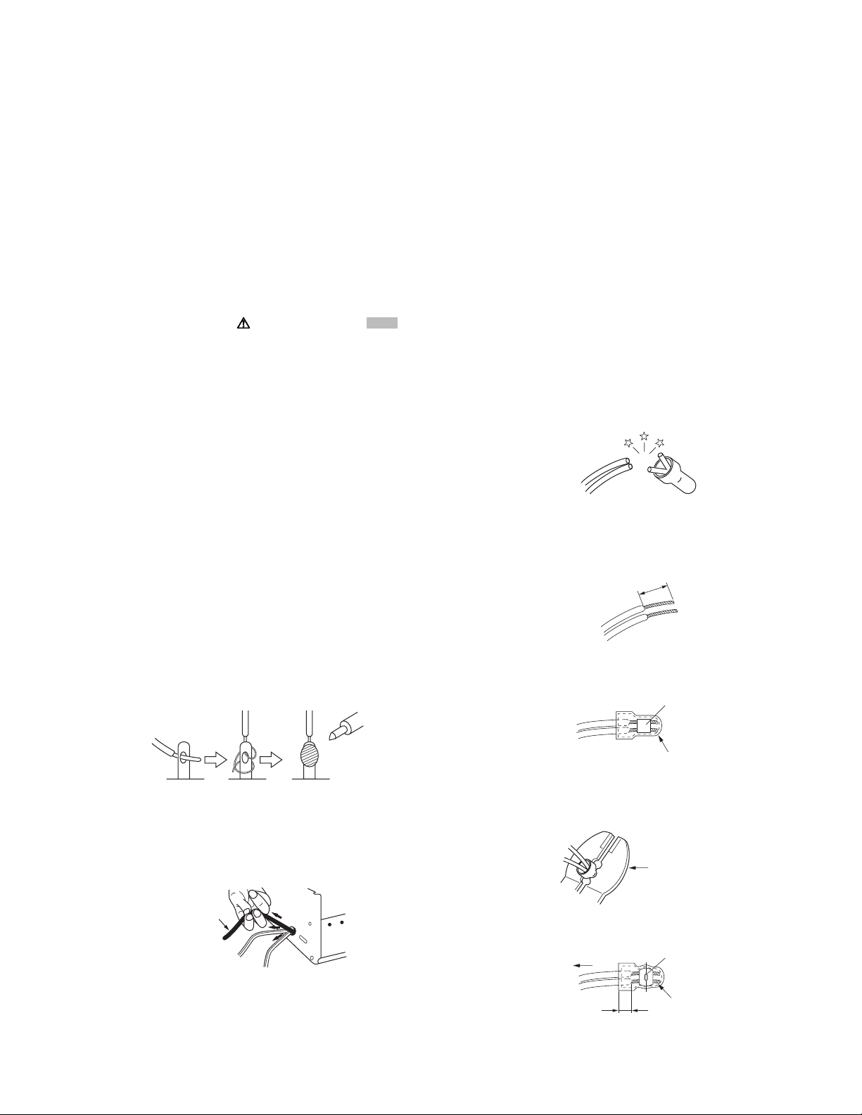
(12) Crimp type wire connectorIn such cases as when replacing
the power transformer in sets where the connections between the power cord and power trans former primary lead
wires are performed using crimp type connectors, if replacing the connectors is unavoidable, in order to prevent safety hazards, perform carefully and precisely according to the
following steps.
• Connector part number :E03830-001
• Required tool : Connector crimping tool of the proper
type which will not damage insulated parts.
• Replacement procedure
a) Remove the old connector by cutting the wires at a
point close to the connector.Important : Do not reuse a connector (discard it).
cut close to connector
Fig.1-1-3
b) Strip about 15 mm of the insulation from the ends
of the wires. If the wires are stranded, twist the
strands to avoid frayed conductors.
15 mm
Fig.1-1-4
c) Align the lengths of the wires to be connected. In-
sert the wires fully into the connector.
Metal sleeve
Fig.1-1-1
(7) Observe that wires do not contact heat producing parts
(heatsinks, oxide metal film resistors, fusible resistors, etc.)
(8) Check that replaced wires do not contact sharp edged or
pointed parts.
(9) When a power cord has been replaced, check that 10-15
kg of force in any direction will not loosen it.
Power cord
Fig.1-1-2
(10) Also check areas surrounding repaired locations.
(11) Products using cathode ray tubes (CRTs)In regard to such
products, the cathode ray tubes themselves, the high voltage circuits, and related circuits are specified for compliance with recognized codes pertaining to X-ray emission.
Connector
Fig.1-1-5
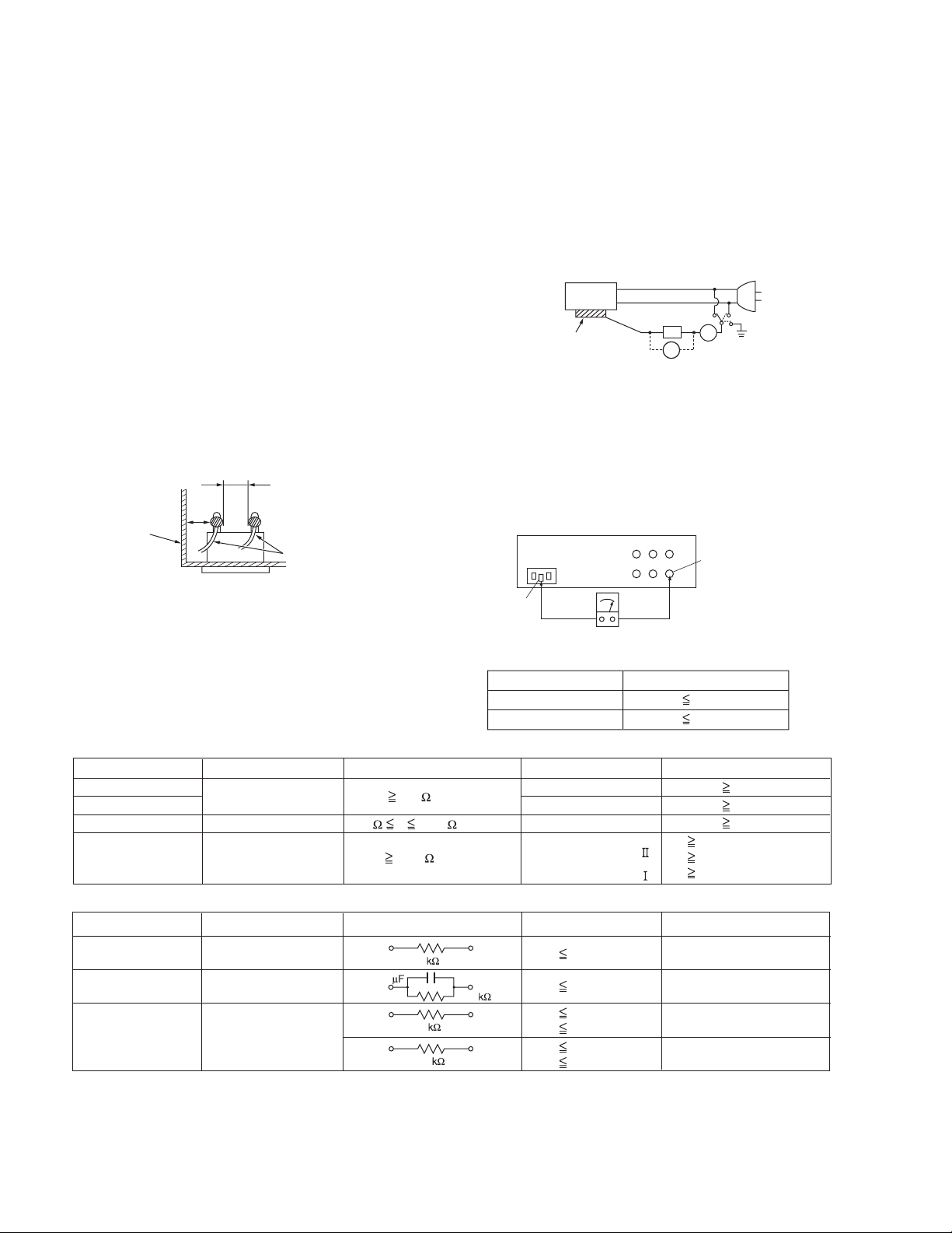
d) As shown in Fig.1-1-6, use the crimping tool to crimp
the metal sleeve at the center position. Be sure to
crimp fully to the complete closure of the tool.
1.2
5
2
.0
5.5
Crimping tool
Fig.1-1-6
e) Check the four points noted in Fig.1-1-7.
Not easily pulled free
Wire insulation recessed
more than 4 mm
Crimped at approx. cente
of metal sleev
Conductors extended
Fig.1-1-7
(No.PA018)1-3
Page 4
1.1.2 Safety Check after Servicing
Examine the area surrounding the repaired location for damage
or deterioration. Observe that screws, parts and wires have been
returned to original positions, Afterwards, perform the following
tests and confirm the specified values in order to verify compliance with safety standards.
(1) Insulation resistance test
Confirm the specified insulation resistance or greater between power cord plug prongs and externally exposed
parts of the set (RF terminals, antenna terminals, video and
audio input and output terminals, microphone jacks, earphone jacks, etc.).See table 1 below.
(2) Dielectric strength test
Confirm specified dielectric strength or greater between
power cord plug prongs and exposed accessible parts of
the set (RF terminals, antenna terminals, video and audio
input and output terminals, microphone jacks, earphone
jacks, etc.). See Fig.1-1-11 below.
(3) Clearance distance
When replacing primary circuit components, confirm specified clearance distance (d), (d') between soldered terminals, and between terminals and surrounding metallic
parts. See Fig.1-1-11 below.
d
Chassis
d'
Power cord
primary wire
Fig.1-1-8
(4) Leakage current test
Confirm specified or lower leakage current between earth
ground/power cord plug prongs and externally exposed accessible parts (RF terminals, antenna terminals, video and
audio input and output terminals, microphone jacks, earphone jacks, etc.).
Measuring Method : (Power ON)Insert load Z between
earth ground/power cord plug prongs and externally exposed accessible parts. Use an AC voltmeter to measure
across both terminals of load Z. See Fig.1-1-9 and following Fig.1-1-12.
ab
Externally
exposed
accessible part
Z
V
c
A
Fig.1-1-9
(5) Grounding (Class 1 model only)
Confirm specified or lower grounding impedance between
earth pin in AC inlet and externally exposed accessible
parts (Video in, Video out, Audio in, Audio out or Fixing
screw etc.).Measuring Method:
Connect milli ohm meter between earth pin in AC inlet and
exposed accessible parts. See Fig.1-1-10 and grounding
specifications.
AC inlet
Earth pin
Exposed accessible part
MIlli ohm meter
Grounding Specifications
Region
USA & Canada
Europe & Australia
Grounding Impedance (Z
Z 0.1 ohm
Z 0.5 ohm
)
Fig.1-1-10
AC Line Voltage
100 V
100 to 240 V
110 to 130 V
110 to 130 V
200 to 240 V
Region
Japan
USA & Canada
Europe & Australia
Insulation Resistance (R
R 1 M /500 V DC
1 M R 12 M /500 V DC
R 10 M /500 V DC
)
Dielectric Strength
AC 1 kV 1 minute
AC 1.5 kV 1 minute
AC 1 kV 1 minute
AC 3 kV 1 minute
AC 1.5 kV 1 minute
(
Class
(
Class
Clearance Distance (d), (d'
d, d' 3 mm
d, d' 4 mm
d, d' 3.2 mm
d 4 m m
)
d' 8 m m (Power cord
d' 6 m m (Primary wire
)
Fig.1-1-11
AC Line Voltage
100 V
110 to 130 V
110 to 130 V
220 to 240 V
Region
Japan
USA & Canada
Europe & Australia
Load Z
1
0.15
1.5
2
50
Leakage Current (i)
i 1 mA rms
i 0.5 mA rms
i 0.7 mA peak
i 2 mA dc
i 0.7 mA peak
i 2 mA dc
a, b, c
Exposed accessible parts
Exposed accessible parts
Antenna earth terminals
Other terminals
Fig.1-1-12
NOTE :
These tables are unofficial and for reference only. Be sure to confirm the precise values for your particular country and locality.
)
)
)
1-4 (No.PA018)
Page 5
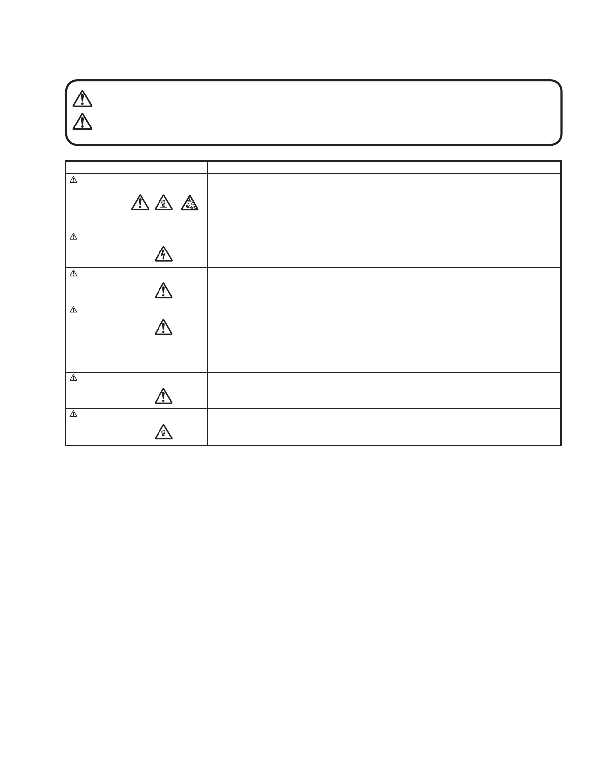
1.1.3 Warning and caution labels
• Labels advising of warning and caution are affixed on and in various locations of the product.
• Take careful notice of these during service and inspection.
WARNING Risk of lethal or otherwise serious personal injury.
CAUTION Risk of personal injury and damage to the product.
Class Pictorial Label advisory Location
WARNING
WARNING
Hot, breakable This projector lamp emits high heat and contains high-pressure during use.
If touched, the lamp (bulb) may rupture and burns may result. Before
attempting to replace the lamp, remove the power cord plug from the outlet and
wait for the lamp (bulb) to cool (at least one hour). Then proceed to replace the
lamp.
High voltage Never open any cover on the projector except the lamp and filter covers.
Dangerous electrical voltage inside the projector.
Bottom chassis
Bottom chassis
WARNING
CAUTION
CAUTION
CAUTION
High brightness Never look into the lens while the projector is on.
There is danger of eye damage.
Hot, shock hazard
High voltage
Hot Caution, high temperature Lamp unit
Do not insert foreign objects into the ventilation holes as this can result in fire or
electrical hazards.
Do not block the ventilation holes as this may cause the internal temperature to
rise and possibly result fire.
When the inside of the unit requires cleaning, consult your nearest JVC dealer
or service center.
Turn off before opening this lamp cover. See user's manual for replacing the
lamp. Replace with the same type (BHL5006-S) lamp rated 250W.
Top cover
Bottom chassis
Bottom chassis
1.1.4 Additional cautionary items
• High voltage is applied for lighting the lamp. During adjustments and other work with the cover removed, extreme care is needed to
avoid electric shock.
• Use care to avoid touching the fan or safety switch terminals during work with the cover removed.
• Select a stable, horizontal work site to prevent dropping the product and components.
• Use the power cord and interface cable supplied with the product.
Before starting work, be sure to also check the safety notices contained in the instruction manual.
(No.PA018)1-5
Page 6

1.2 INSTALLATIONS
1.2.1 Installation method
The D-ILA system (reflecting type active matrix liquid crystal system) does not require convergence adjustment. Note the following
when placed on a floor (refer to OPERATING INSTRUCTIONS for actual operating method).
(1) Place the projector at the position needed for the required image size observe the projector is not tilted horizontally.
[The image size is 37 to 275(wide side) inches diagonal (16:9), requiring a projection distance of 2m to 12m (tele side).]
(2) Adjust the placement site and screen tilt so that the projection angle is perpendicular to the screen.
(3) Adjust the placement site and screen position (height) so that the projection lens center is at the lower edge of the screen.
(4) Project an image on the screen. (Connect video equipment and power source, switch power on and select the input.)
(5) Fine adjust the projected image position and angle. If adjusting the placement site and screen cannot correct the projected po-
sition (too low) or angle (lower part of image widened), adjust the front foot.
(6) Turn the lens ZOOM ring by hand and adjust for suitable image size.
(7) Turn the lens FOCUS ring by hand and adjust to correct image blur.
(8) Adjust [KEYSTONE] if the image appears expanded or contracted at the top or bottom edge.
(9) Adjust < Image adj. > - [Brightness], [Contrast], [Sharpness], [Color] and [Tint] for optimum picture.
1.2.2 Installation site and status
• The projector contains a fan for cooling. Obstruction of the ventilation openings can lead to internal overheating, abnormal operation
and failure. Also observe there is plenty of free space between the projector and adjacent walls, ceiling and other equipment.
Note that excess heat can cause failure and damage to both the projector and nearby equipment.
Required spacing :
Front = 15cm / left and right sides = 30cm / rear = 50cm (When the unit is enclosed with block according to the required spacing
on the left side, provide the unit with adequate ventilation so that the temperature inside of the enclosed area is kept at the same
temperature in the open space in the room.)
• Avoid locations that are wobbly or inclined. If the setting site floor has protrusions or horizontal cannot be maintained, there is risk
the projector may drop, fall over, etc. If located in a site where left to right tilt is greater than ±5° and front to rear tilt greater than
±20°, particularly the optical system components can be severely affected and there is risk basic performance and quality of the
projector cannot be maintained.
• Observe the site can stably bear the weight (approx. 6kg) of the projector over a long period of time.
• If mounted on a stand with casters, observe the casters are securely braked to prevent movement.
• Avoid suspending in a location subject to vibration. Both the projector and mounting fixture can be damaged.
• Do not place in the following types of locations.
Especially, Avoid locations subject to dust, grit, smoke or other airborne contaminants. Use adequate caution when providing external ventilation, filters and dust protection.
Near water or in humid sites Near heaters or heat generating equipment
Dust or grit Direct sunlight
Oily or tobacco smokes Very high or very low temperature
1-6 (No.PA018)
Page 7
SPECIFIC SERVICE INSTRUCTIONS
TOP VIEW (Operation Panel)
2.1 FUNCTIONS
2.1.1 LED indications
The LED operations are as follows.
OPERATE LED
Lighted : Power on mode in progress.
Extinguished : Mode other than above.
STAND-BY LED
Lighted : Stand-by mode in progress.
Flashing : Cool down mode in progress.
Extinguished : Mode other than above.
TEMP LED
Flashing : Internal temperature abnormally high
(shift to emergency mode) .
Extinguished : Internal temperature normal.
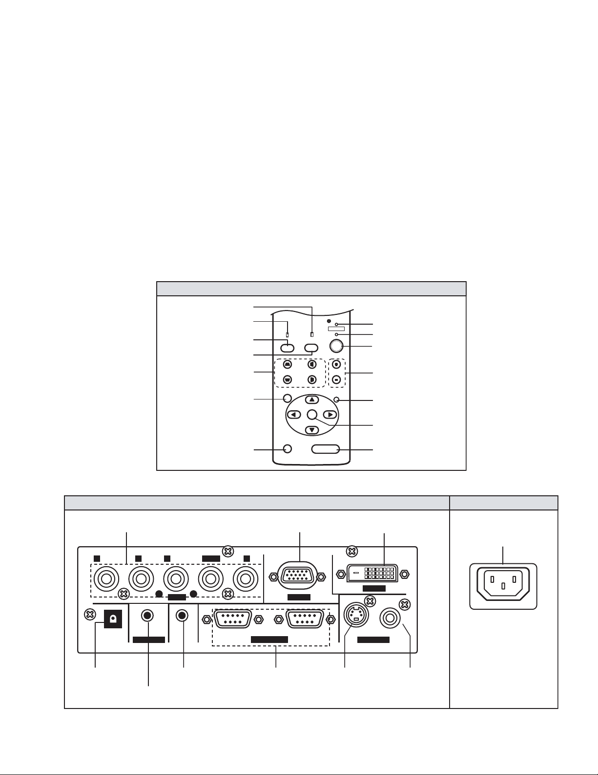
2.1.2 Operation button & LED location
TOP VIEW (Operation Panel)
TEMP LED
LAMP LED
PC BUTTON
VIDEO BUTTON
KEYSTONE BUTTON
SECTION 2
LAMP LED
Lighted : Lamp replacement time near (used approx.1900
Flashing : Lamp end of life (approx. 2000 hours), power
Extinguished : Mode other than above
NOTE :
Please refer to troubleshooting about the warning display by
LED.
STAND BY
OPERATE
TEMP
LAMP
VIDEO
PC
H-KEYSTONEV-KEYSTONE
VOL.
hours) At power on, message appears by the onscreen display for advising to "LAMP REPLACE".
on inhibited.
(lamp abnormally absent) .
STAND BY LED
OPERATE LED
OPERATE BUTTON
VOLUME BUTTON
MENU BUTTON
PRESET BUTTON
2.1.3 Input / output terminal location
PC2 INPUT
PB/CBPR/CR Y
TRIGGER
SCREEN TRIGGER
OUTPUT
AUDIO IN
AUDIO INPUT
REMOTOSCREEN
REMOTE
INPUT / OUTPUT
MENU
PRESET
RIGHT SIDE
H/Cs VBGR
RS-232C OUT RS-232C IN
INPUT / OUTPUT
PC1 INPUT DVI INPUT
PC 1PC 2
CONTROL
RS-232C
EXIT
ENTER
HIDE
EXIT BUTTON
ENTER BUTTON
HIDE BUTTON
DVI
PC 3
VIDEO Y/C
VIDEO IN
Y/C INPUT VIDEO INPUT
LEFT SIDE
POWER INPUT
(No.PA018)1-7
Page 8
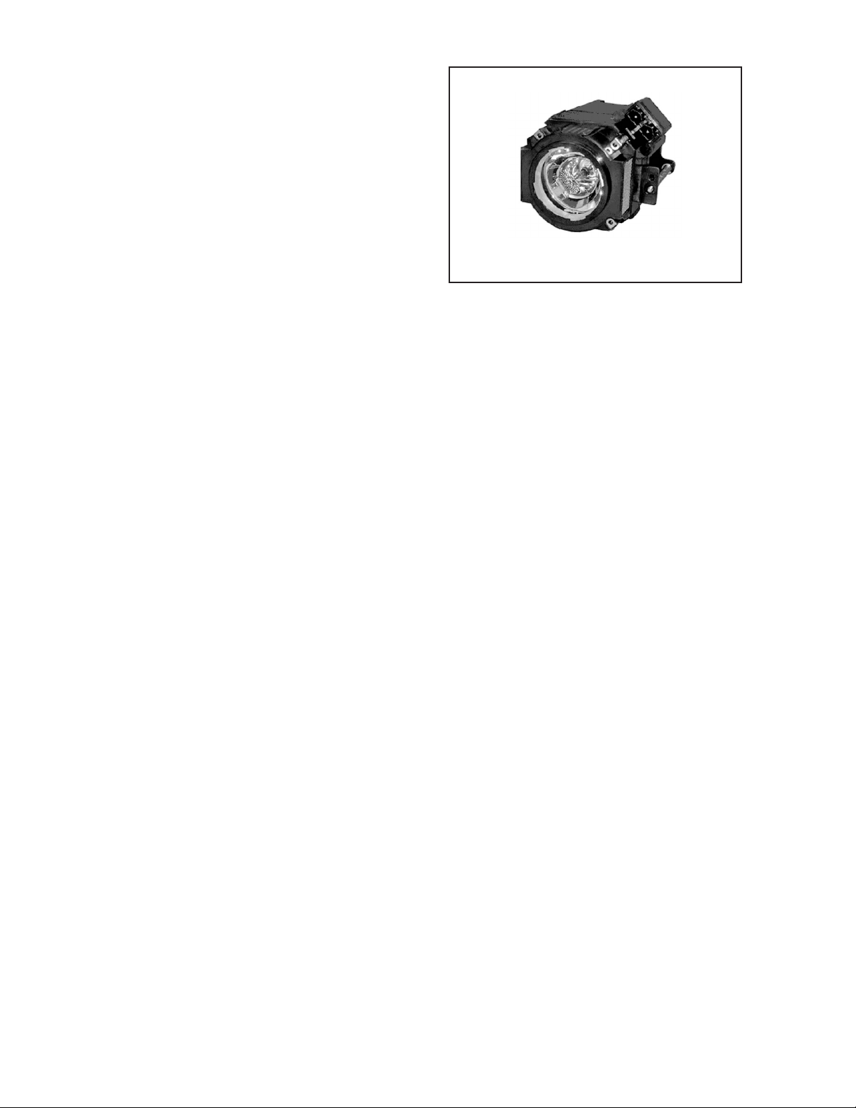
2.2 LAMP UNIT INSTRUCTIONS
Refer to the OPERATING INSTRUCTIONS for a detailed operating description.
2.2.1 Lamp life
Life of the projector lamp (time to reach 1/2 average brightness)
is about 2000 hours.
∗ Lamp use time can be checked at the menu < Information > -
[Lamp time].
LAMP UNIT : BHL5006-S
2.2.2 Operation when lamp use time exceeds 1900 hours
z 1900 to 2000 HOURS
• Power on : LAMP LED lights.
• Operation : Lamp replacement lamp message appears on
screen (∗press any button to extinguish).
z 2000 to 2010 HOURS
• Power on : LAMP LED flashes.
• Operation : "Warning" and "Lamp replacement" messages
appear on screen, and "Warning" flashes.
∗Press [EXIT] button to extinguish the display. But after 1
hour, "Warning" and "Lamp replacement" again appear.
NOTE:
At power off, the stand-by mode is produced and further operation is prevented.
∗To again use the projector, replace the lamp unit and reset
the lamp use time indication.
z AFTER 2010 HOURS
• Power on : Power is cut and cool-down mode entered,
LAMP and OPERATE LEDs flash.
2.2.3 Handling cautions
• Use a cross-head screwdriver to take out and reinstall the lamp
cover (2 screws) and lamp unit (2 screws). Refer to the OPERATING INSTRUCTIONS.
• Observe the following cautions.
- Be sure to disconnect the power cord from the AC power
source.
- The lamp remains quite hot after power off. Be sure to allow
plenty of time (30 minutes to 1 hour) to cool before proceeding.
- The lamp can break if dropped or subjected to physical
shock.
- Use care not to directly touch or soil the lamp projecting
(glass) face.
• When installing the lamp unit, observe the interior projections
of the lamp cover are securely inserted into the holes of the
projector. Since the lamp cover projections engage the interlock switch part of the protector circuit (normal operating state),
be sure the cover is properly positioned and secure with
screws.
• The replaced old lamp (depleted lamp unit) can be discarded
in the same manner as a fluorescent lamp. Check local ordinances and dispose of the used lamp as prescribed.
2.2.4 Lamp use time reset
• Be sure to reset the Lamp use time after replacing the lamp
unit. Unless reset, the projector will cease operation (lamp will
not light) when 2000 hours are reached.
∗Conversely, reset the use time only after replacing the lamp.
• RESETTING
(1) Set for stand-by mode.
(2) In sequence, press the [EXIT], [HIDE] and [PRESET]
buttons.
(3) Press the [VOL+] button for more than 2 seconds.
∗The STAND-BY and OPERATE LEDs alternately flash
for about 3 seconds, then only the STAND-BY LED
lights steadily.
• RESET AFTER REPLACING MAIN PWB ASS'Y
The lamp use time data are stored in memory on the MAIN
PWB ASS'Y and need to be reentered after replacing the
MAIN PWB ASS'Y. Use the special software and a personal
computer to reenter the data. Afterwards, confirm the mode
has been returned to that prior to board replacement.
1-8 (No.PA018)
Page 9
2.3 PROJECTION SPECIFICATIONS AND NOTES
2.3.1 Projection distance
• The usable projection distance (focus obtainable) is tele side :
approx. 2m to 11.5m / wide side : approx. 1.6m to 12m. The
picture size (16:9) is 37 to 275 inches.
• Use the wide side for sizes bigger than 200 inches.
• If picture edge distortion occurs at the minimum distance
(1.6m), increase the distance slightly.
• The guaranteed projection distance range is from 2m to 10m.
2.3.2 Projection image and image size
• The projection distances and image size relationship given in
the operation manual is approximate for general reference.
The actual values may vary due to lens tolerance and other
factors.
• A distance between a horizontal line that passes a center of
the projection lens of this model and a bottom of the projection
screen is one-thirtieth of the vertical size of the screen. (See
the Instruction Manual.)
• The projector a horizontal (vertical line) "keystone (trapezoid
distortion)" due to projection angle wavering corrective function. Keystone compensation yields a smaller image than the
uncompensated picture. When the image is important, to the
extent possible, correct by selecting the projector position,
screen front to rear tilt and projection angle (perpendicular) to
the screen.
2.3.3 Other cautions
• Use care not to directly touch the lens. Clear soiling from the
lens with optical lens paper or a photographer's blower.
• Check the lens cap is removed before projecting. If left installed the projector can overheat and the lens cap can be deformed.
• Sunlight or other illumination can render the image difficult to
see. Use a curtain or other means to shield the screen from
stray light.
2.5 SERVICE POLICY
The following service policy is being utilized.
Item Parts number Service method
MAIN PWB ASS'Y SXZ-1006A Replace parts
DD SUB PWB ASS'Y SXZ-3002A Replace parts
POWER PWB ASS'Y SXZ-9001A Replace parts
TERMINAL PWB ASS'Y SXZ-0J003A Replace parts
IR PWB ASS'Y SXZ-0R001A Replace parts
CONT. & 3.3V PWB ASS'Y SXG-0P002A Replace parts
OPTICAL BLOCK ASS'Y HX1OP-S Replace (module)
LAMP BALLAST UNIT QAL0435-002 Replace (module)
LAMP UNIT BHL5006-S Replace (module)
2.4 CONNECTION AND OPERATION CAUTIONS
• The projector can function with fH 15 to 120 kHz, fV 24Hz,
25Hz, 30Hz, 50Hz to 120 Hz signal input, but even within this
range, partial picture loss, fold-over at the top and bottom picture edges and other effects can occur according to signal type
and conditions to prevent a normal projected image (see "Signals that can be input the projector" of the OPERATING INSTRUCTION).
• The projector is compatible with UXGA input (H : 1600 ~ V :
1200 dots).
• VGA computer signal may be detected and displayed as 480p
mode of the video system. Select the video system input at the
menu.
• If the video signal from a VTR or other source contains a large
jitter component, distortion, blurring or instability can occur in
the picture. In this case, use a TBC (time base corrector) or
video equipment (e.g., VTR) that contains a TBC.
• The digital zoom and still picture (freeze) functions do not operate with UXGA signal input. When these functions are desired, use another signal input.
• The menu indication differs when the input is selected for video
system or computer system. See below.
Item VIDEO COMPUTER
< Image adj. > Sharpness Present Present ∗1
< Set up > Decoder Present Absent
< Set up > Deinterlace Present Absent
< Set up > Aspect ratio Present Absent
< Set up > HDTV Present Absent
< Set up > Tracking Absent Present
< Setting > Resize Absent Present
< Set up > Clamp Absent Present
< Set up > Sync level Absent Present ∗2
∗1 : If the "Resize" function is the PC submenu is set to "1:1", the
image quality will not change even if the value is changed.
(No adjustment)
∗2 : This will be displayed at the no-signal status when PC1 and
PC2 is selected.
2.6 MAIN DIFFERENCE LIST
Part name DLA-HX1U DLA-HX1E Remark
PACKING CASE LC21468-003A LC21468-004A
POLY BAG QPA01503005 -------- For Warranty card
WARRANTY CARD BT-51030-2 -------- Accessory
POWER CORD QMPE320-200-R
INST. BOOK LCT1511-001A (ENG/FRA) LCT1512-001A (
QMPL280-200-R (for EU)
QMPP220-200-R (for UK)
ENG/FRA/GER/ITA/SPA/KOR
Accessory
) Accessory
(No.PA018)1-9
Page 10
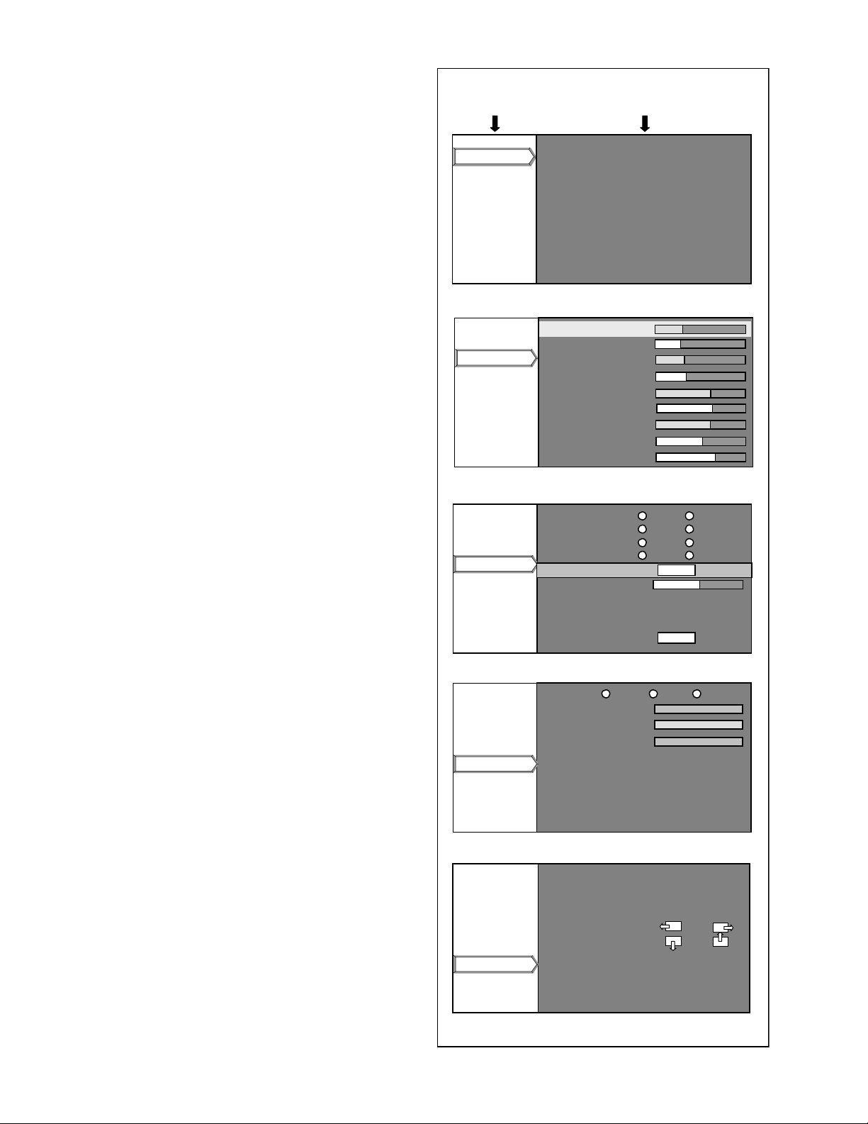
2.7 SERVICE MENU
Horizontal resolution
Vertical resolution
Tracking
Position of Horizontal display
Position of Vertical display
The service menu contains items not ordinarily needed by the user. Use these as necessary during service.
2.7.1 Enter
(1) No menu shown.
(2) Press the [] button.
(3) Within press the [] button.
(4) Within press the [] button.
(5) Within press the [] button.
(6) Within press the [ENTER] button to display the service
menu.
NOTE:
When the Service Menu Screen is not displayed, go back to
the beginning. It is recommended that you press the buttons a
little earlier and steadily.
2.7.2 Release
Press the [MENU] button to exit the menu indication.
2.7.3 Basic operation
Use the following buttons to operate the service menu.
(1) Choose the SETTING MENU with the [/] button.
(2) When the [] button is pressed after choosing the SET-
TING MENU, the cursor will shift to the SETTING / ADJUSTMENT ITEMS of each SETTING MENU.
(3) When the cursor is shifted, choose the SETTING / AD-
JUSTMENT ITEMS with the [/] button.
(4) Using the [/] button, change the setup values and ad-
justment values, respectively.
(5) When the [EXIT] button is pressed, the cursor will return to
the SETTING MENU.
(6) When the [MENU] button is pressed, the SERVICE MENU
will go out of the screen.
NOTE:
The SERVICE MENU will go out of the screen automatically
after 10 seconds if you do not press the [MENU] button.
SETTING NENU
Software version
Cont. / Bright
Option
Color temp
Resolution
Software version
Cont. / Bright
Option
Color temp
Resolution
Software version
Cont. / Bright
Option
Color temp
Resolution
SERVICE MENU
SETTING / ADJUSTMENT ITEM
MODEL NAME : DL
PR OGRAM : 7
OSD : 3
DLAHX1_00003_2003_0826_01
Software version SCREEN
Contrst_R 80
Contrast_R 80
Contrast_G
Contrast_B
Contrast_Main
Brightness_R
Brightness_G
Brightness_B
Cb
Cr
Cont. / Bright SCREEN
VGA mode VGA
Back color Black
Auto shutdown OFF
Over scan
Test pattern
Sharp ness
All reset
A-HX1
HDCP
72
87
90
166
167
165
33
41
480p
Blue
ON
Normal
ENTER
0
ENTER
Overscan
Software version
Cont. / Bright
Option
Color temp
Resolution
Software version
Cont. / Bright
Option
Color temp
Resolution
Option SCREEN
Color temp 6500 STD User
RED
GREEN
BLUE
0
0
0
Color temp SCREEN
Horizontal resolution
Vertical resolution
Tracking
Position of Horizontal display
Position of Vertical display
Resolution adjustment SCREEN
1234
1234
123
12
12
1-10 (No.PA018)
Page 11
2.7.4 Setting items
Item Initial value
Adjustment
range
Description
Software version
Software version ------ ------ Information of PROGRAM -----Cont. / Bright
Contrast
R / G / B / Main
Brightness
R / G / B
[Service adjust.
value]
[Service adjust.
value]
0 ~ 255 Main contrast adjustment. Common
0 ~ 255 Main brightness adjustment. Common
Cb / Cr 31 0 ~ 31 Component signal adjustment. AV system
Option
VGA mode* 480p [Select 2 items] Sets processing for VGA signal input (H : 31.5 kHz / V : 60 Hz).
[480p] : Process as 480p (video system) signal
[VGA] : Process as VGA (PC system) signal
Back color Blue [Select 2 items] "Sets no signal background color to blue or black.
[Blue] : Blue color [Black] :Black color"
Auto shutdown ON [Select 2 items] If POWER OFF is selected, no warning will be displayed on and after 1900
hours of the lamp operating time. However, POWER ON is also available
after 2000 hours of the lamp operating time.
Over scan* Over scan [Select 2 items] Sets scan size for video signal.
[Normal] : Under scan (100%) [Over scan] : Normal (95%)
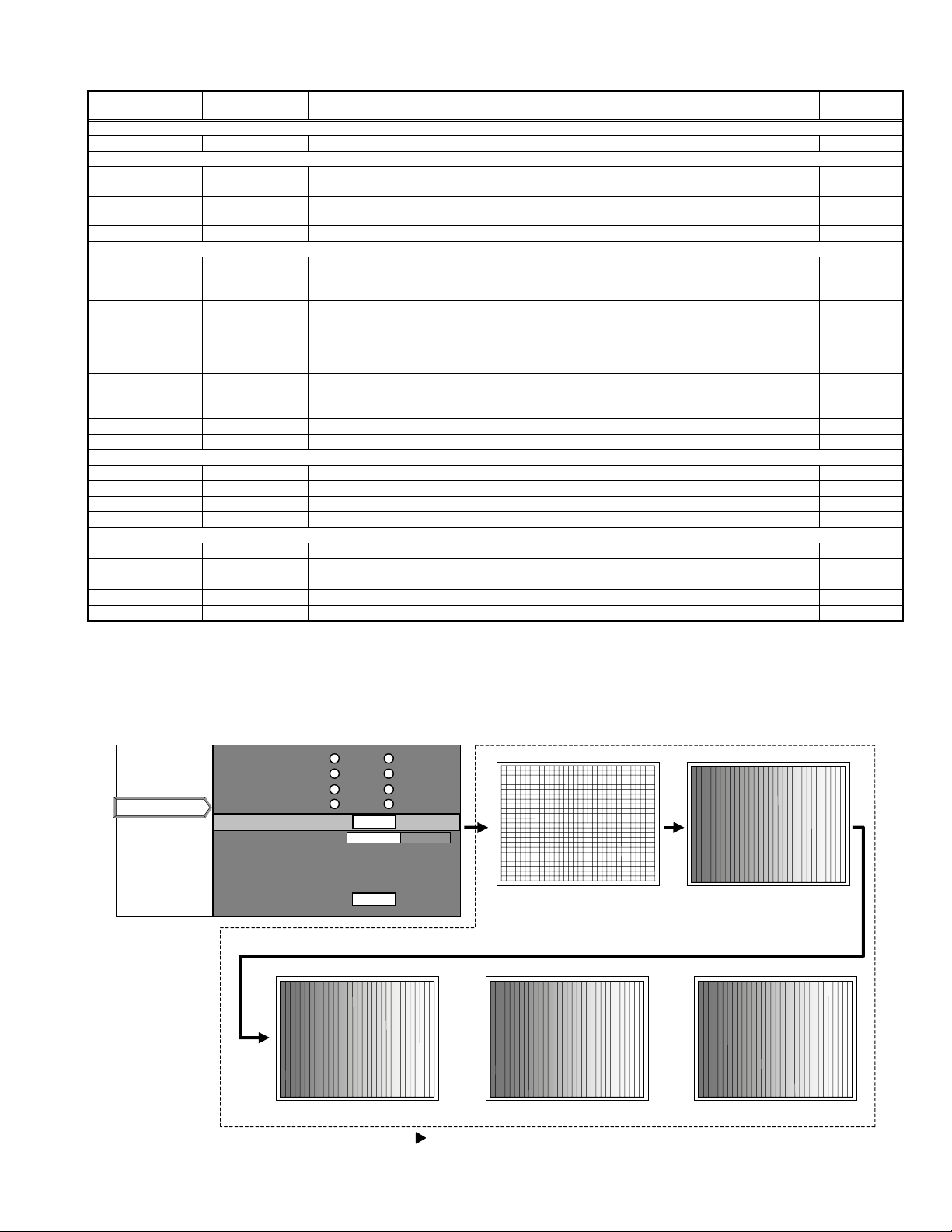
Test pattern ------ [Select 5 items] Press [ENTER] then Test pattern appear. (Refer to following Fig.1) Common
Sharpness 0 -3~3 Main sharpness adjustment. Common
All reset ------ ------ Press [ENTER] then all reset. Common
Color temp
Color temp User Select 3 items Setting of [6500] [Normal] [User] Common
R 0 -255~0 Setting color temp of red Common
G 0 -255~0 Setting color temp of green Common
B 0 -255~0 Setting color temp of blue Common
Resolution
Horizontal resolution
Vertical resolution
Tracking
Position of Horizontal display
Position of Vertical display
Depending on signals
Depending on signals
Depending on signals
Depending on signals
Depending on signals
← Set the horizontal resolution
← Set the vertical resolution
← Same as for the tacking in the User Menu
← Same as for the display of the horizontal position in the User Menu
← Same as for the display of the vertical position in the User Menu
Setting
object
Each signal
(VGA)
Common
Common
Each signal
(AV system)
Analog PC signal
Analog PC signal
Analog PC signal
Analog PC signal
Analog PC signal
∗ : When these items are set, the service menu is automatically closed.
Notice on items in relation to resolution
(1) These functions may sometimes not project some types of signals properly.
(2) These functions cannot set resolution of signals that are input from DVI terminal and video signals (displayed in video menu).
(3) Method of changing the resolution (See the next page.)
Test patter Screen
Software version
Cont. / Bright
Option
Option
Color temp
SERVICE MENU Screen
VGA mode 480p VGA
Back color Blue Black
Auto shutdown ON OFF
Over scan Normal Over scan
Test pattern
Test pattern
Sharp ness 0
ENTER
All reset
ENTER
cross-hatch Gray scale
Red Green Blue
(When the key is pressed, the screen is changed one after the other as shown in the above.)
(No.PA018)1-11
Page 12

HOLIZONTAL RESOLUTION CHANGE PROCEDURE
Start
Set the horizontal position
to the minimum value.
Set the tracking value in
accordance with the Formula1
on the right side.
Change the horizontal
resolution.
Is it changed?
Yes
Formula1
...
New tracking = Previous tracking New horizontal resolution Previous horizontal resolution
No
Previous resolution>New resolution?
Yes
Decrease the tracking value.
No
Increase the tracking value.
Quick Alignment
Check it by referring to
the information in Menu.
1-12 (No.PA018)
End
Yes
Change the horizontal resolution.
Is it changed?
No
This signal cannot be changed.
Page 13

VERTICAL RESOLUTION CHANGE PROCEDURE
Start
Set the vertical position to
the minimum value.
Change the vertical resolution.
Is it changed?
Yes
Quick Alignment
Check it by referring to
the information in Menu.
End
No
This signal cannot be changed.
(No.PA018)1-13
Page 14

2.8 FACTORY SHIPPING SETTING
SET (PROJECTOR) / REMOTE CONTROL UNIT
Switch / Item
MAIN POWER
VIDEO
PC
MENU
Item
Image adj. (VIDEO INPUT/ COMPUTER INPUT)
Contrast
Brightness
Color
Tint
Sharpness
Color temp.
Color temp.
RED
GREEN
BLUE
Reset
Set up
Position
Menu pos.
Horiz. disp. pos.
Vert. pos.
Horiz. DIST pos. *
2
Film*
2
HDTV*
Aspect ratio*
2
Aspect ratio
2
Color*
Tracking *
1
Phase
Resize *
1
Resize
Clamp *
Sync level *
1
3
2
Position
OFF
VIDEO
PC1
Position
0
0
0
0
0
ENTER
6500
0
This adjustment is only
available when the USER is
0
selected for color temperature.
0
ENTER
ENTER
4
351*
4
42*
0
AUTO
1080i
ENTER
4
16:9*
ENTER
4
1688*
4
20*
ENTER
Aspect
BP
Std
Switch / Item
VOLLUME
FREEZE
HIDE
Item Position
Logo
Logo disp.
Logo pos.
Back color
Logo delete
Capture menu
Option
( Page1 )
Color profile
Menu display
Line display
Flip H
Flip V
( Page2 )
Sleep time [min]
Menu color
PC2(BNC)
DET
SCART
RS-232C[bps]
SXGA
PC3
Language
Position
0
OFF (moving picture)
OFF (display)
ON
Center
Black
ENTER
ENTER
ENTER
15sec
5sec
OFF
OFF
OFF
OFF
YPbPr
ON
OFF
19200
1280
HDCP
English
*1 : Only when PC system signal selected
*2 : Only when VIDEO system signal selected
*3 : Only non signal
*4 : It changes with input signals.
1-14 (No.PA018)
Page 15

SECTION 3
DISASSEMBLY
Notes:
• Confirm that the power cord is unplugged from the AC outlet before proceeding.
• The lamp remains quite hot after turning the power off. Allow sufficient time to cool before starting work.
3.1 LENS COVER
(1) Rotate the LENS COVER on the front of the main frame
counterclockwise and release the lock. Then pull out the
LENS COVER toward you. (Fig.1)
3.2 LAMP UNIT COVER
(1) Loosen the 2 screws marked A on the right side of the main
frame and pull out the LAMP UNIT COVER toward you.
(Fig.2)
These 2 screws are not removed from the LAMP UNIT
COVER.
3.3 TOP COVER
• Remove the LENS COVER.
• Remove the LAMP UNIT COVER.
(1) Remove the 1 screw marked B and the 3 screws marked C
on the right side of the main frame. (Fig.2)
(2) Remove the 3 screws marked D on the left side of the main
frame. (Fig.2)
(3) Remove the 1 screw marked E on the rear side of the main
frame. (Fig.2)
(4) Remove the harness from the connector CN701
CONTROL UNIT which is secured to the back of the TOP
COVER.
(5) Lift up the TOP COVER to remove it.
3.4 PROTECT COVER
• Remove the LENS COVER.
• Remove the LAMP UNIT COVER.
• Remove the TOP COVER.
(1) Remove the 1 screw marked E' fixing the PROTECT COV-
ER, and lift up the PROTECT COVER to remove it. (Fig.2)
3.5 CONTROL UNIT
• Remove the LENS COVER.
• Remove the LAMP UNIT COVER.
• Remove the TOP COVER.
(1) Remove the 5 screws marked F fixing the CONTROL UNIT
from the back of the TOP COVER. (Fig.2)
(2) Remove the CONTROL UNIT. (Fig.2)
of the
LENS COVER
Fig. 1
D
(x3)
(x1)
CN710
TOP COVER
E'
F
(x5)
CONTROL UNIT
C
(x1)
E
(x1)
A
(x2)
LAMP UNIT COVER
BOTTOM CHASSIS
Fig.2
C
(x2)
B
(x1)
(No.PA018)1-15
Page 16

3.6 TERMINAL PWB ASS'Y AND MAIN PWB ASS'Y
• Remove the LENS COVER.
• Remove the LAMP UNIT COVER.
• Remove the TOP COVER.
(1) Remove the 6 screws marked J fixing the MAIN PWB
ASS'Y. (Fig.3)
(2) Remove the harness from the connectors CN710
, and CN001.
CN701
, CN711,
(3) Remove the cord wire from the connector CN801.
(4) Remove the harness from the connectors CN800
, CN706, CN705, CN713, CN704, and CN708.
CN707
, CN714,
3.7 TERMINAL BOARD AND SHIELD SHEET
• Remove the LENS COVER.
• Remove the LAMP UNIT COVER.
• Remove the TOP COVER.
• Remove the TERMINAL PWB ASS'Y AND MAIN PWB ASS'Y. *1
(1) Remove the 5 screws marked G fixing the TERMINAL
BOARD. (Fig.3)
(2) Remove the TERMINAL BOARD.
(3) Using a nut driver and the like, remove the 8 screws
marked H fixing the D-SUB connector and DVI connector.
(Fig.3)
(4) Pull out the SHIELD SHEET toward you to remove it.
*1
After (2) in the procedure above, the TERMINAL BOARD and
the SHIELD SHEET can be replaced. However, be careful
about the cord wire and the harness that are not replaced.
3.8 TERMINAL PWB ASS'Y
• Remove the LENS COVER.
• Remove the LAMP UNIT COVER.
• Remove the TOP COVER.
• Remove the TERMINAL PWB ASS'Y AND MAIN PWB ASS'Y.
• Remove the TERMINAL BOARD and the SHIELD SHEET.
(1) Remove the 1 screw L fixing the TERMINAL PWB ASS'Y.
(2) Disconnect the connector CN010
that connects the TER-
MINAL PWB ASS'Y and the MAIN PWB ASS'Y.
(3) Remove the 1 screw marked L' fixing the bracket, and the
TERMINAL PWB ASS'Y is removed.
3.9 MAIN PWB ASS'Y
• Remove the LENS COVER.
• Remove the LAMP UNIT.
• Remove the TOP COVER.
• Remove the TERMINAL PWB ASS'Y AND MAIN PWB ASS'Y.
• Remove the TERMINAL BOARD and the SHIELD SHEET.
(1) Remove the 1 screw market K fixing the MAIN PWB
ASS'Y.
(2) Disconnect the connector CN010
that connects the MAIN
PWB ASS'Y and the TERMINAL PWB ASS'Y.
CN714
CN707
CN706
CN705
CN713
CN704
CN708
CN701
CN801
CN001
K
CN800
(x1)
L'
(x1)
L
(x1)
CN711
CN010
CN710
J
(x6)
TERMINAL PWB ASS'Y
MAIN PWB ASS'Y
TERMINAL BOARD
SHIELD SHEET
(x4)
H
(x4)
G
(x5)
H
1-16 (No.PA018)
Fig.3
Page 17

3.10 LAMP UNIT UPPER BRACKET
• Remove the LENS COVER.
• Remove the LAMP UNIT.
• Remove the TOP COVER.
• Remove the TERMINAL PWB ASS'Y AND MAIN PWB ASS'Y.
(1) Remove the 2 screws marked M fixing the LAMP UNIT UP-
PER BRACKET. (Fig.4)
(2) Pull out the LAMP UNIT UPPER BRACKET in the direction
of the arrow.
3. 11 POWER SUPPLY SHIELD CASE(1) and LAMP BALLAST UNIT
• Remove the LENS COVER.
• Remove the LAMP UNIT.
• Remove the TOP COVER.
• Remove the TERMINAL PWB ASS'Y AND MAIN PWB ASS'Y.
• Remove the LAMP UNIT UPPER BRACKET.
(1) Remove the 5 screws marked N fixing the POWER SUP-
PLY SHIELD CASE(1). (Fig.4)
(2) Disconnect the connectors CN1
and CN2.
(3) Remove the 1 screw marked O fixing the LAMP POWER
SUPPLY CORD SUPPRESSION BRACKET. (Fig.4)
(4) Lift up the LAMP POWER SUPPLY CORD SUPPRES-
SION BRACKET to remove it, and remove the LAMP
POWER SUPPLY CORD.
(5) After setting up the POWER SUPPLY SHIELD CASE(1),
remove the 4 claws marked a which secure the LAMP BALLAST UNIT to the back of the POWER SUPPLY SHIELD
CASE. (Fig.4)
(x5)
LAMP BALLAST UNIT
POWER SUPPLY SHIELD CASE(1)
CN2
CN1
M
(x2)
a
N
LAMP UNIT UPPER BRACKET
O
(x1)
LAMP POWER SUPPLY CORD
SUPPRESSION BRACKET
LAMP POWER SUPPLY CORD
Fig.4
(No.PA018)1-17
Page 18

3.12 POWER SUPPLY PWB ASS'Y
• Remove the LENS COVER.
• Remove the LAMP UNIT.
• Remove the TOP COVER.
• Remove the TERMINAL PWB ASS'Y AND MAIN PWB ASS'Y.
• Remove the LAMP UNIT UPPER BRACKET.
• Remove the POWER SUPPLY SHIELD CASE(1).
(1) Remove the 4 screws marked P fixing the POWER SUP-
PLY PWB ASS'Y. (Fig.5)
(2) Disconnect the POWER SUPPLY CORD from the connec-
tor CN001
.
(3) Pull out the harness from the THERMOSTAT PROTEC-
TOR.
(4) Pull out the POWER SUPPLY CONTROL MODULE PWB
ASS'Y from CN005. (Fig.5)
3.13 POWER SUPPLY CONTROL MODULE PWB ASS'Y
• Remove the LENS COVER.
• Remove the LAMP UNIT.
• Remove the TOP COVER.
• Remove the TERMINAL PWB ASS'Y AND MAIN PWB ASS'Y.
• Remove the LAMP UNIT UPPER BRACKET.
• Remove the POWER SUPPLY SHIELD CASE(1).
(1) Pull out the POWER SUPPLY CONTROL MODULE PWB
ASS'Y from the connector CN005
of the POWER SUPPLY
PWB ASS'Y. (Fig.5)
3.14 POWER SUPPLY SHIELD CASE(2), RADIATION FAN, INTERLOCK SWITCH, COOLING FAN1, DUCT1
• Remove the LENS COVER.
• Remove the LAMP UNIT.
• Remove the TOP COVER.
• Remove the TERMINAL PWB ASS'Y AND MAIN PWB ASS'Y.
• Remove the POWER SUPPLY SHIELD CASE(1).
• Remove the POWER SUPPLY PWB ASS'Y.
(1) Remove the 4 screws marked Q fixing the POWER SUP-
PLY SHIELD CASE(2). (Fig.5)
(2) Lift up the POWER SUPPLY SHIELD CASE(2) to remove
it.
(3) Remove the 2 screws marked R fixing the RADIATION
FAN to the POWER SUPPLY SHIELD CASE(2). (Fig.5)
(4) Remove the 1 screw marked S fixing the INTERLOCK
SWITCH to the POWER SUPPLY SHIELD CASE(2), and
remove the INTERLOCK SWITCH. (Fig.5)
(5) Remove the 2 screws marked b fixing the DUCT1. (Fig.5)
(6) Remove the 2 screws marked c fixing the COOLING
FAN1. (Fig.5)
b
(x2)
c
(x2)
COOLING FAN1
POWER SUPPLY CONTROL MODULE PWB ASS'Y
CN005
DUCT1
POWER SUPPLY SHIELD CASE(2)
CN001
P
(x4)
R
(x2)
Q
(x4)
RADIATION FAN
S
(x1)
INTERLOCK SWITCH
THERMOSTAT PROTECTOR
1-18 (No.PA018)
Fig.5
Page 19

3.15 IR PWB ASS'Y
• Remove the LENS COVER.
• Remove the LAMP UNIT.
• Remove the TOP COVER.
• Remove the TERMINAL PWB ASS'Y AND MAIN PWB ASS'Y.
(1) Remove the 1 screw marked T fixing the IR PWB ASS'Y.
(Fig.6)
(2) Lift up the IR PWB ASS'Y to remove it.
3.16 OPTICAL BLOCK, INTAKE FAN
• Remove the LENS COVER.
• Remove the LAMP UNIT COVER.
• Remove the TOP COVER.
• Remove the TERMINAL PWB ASS'Y AND MAIN PWB ASS'Y.
(1) Remove the 1 screw marked o fixing the LAMP POWER
SUPPLY CORD SUPPRESSION BRACKET. (Fig.4)
(2) Pull out the LAMP POWER SUPPLY CORD
(3) Remove the 2 screws marked j fixing the THERMOSTAT
PROTECTOR. (Fig.6)
(4) Remove the 2 screws U and 3 screws v fixing the OPTICAL
BLOCK. (Fig.6)
(5) Remove the 1 screw k fixing the EARTH BRACKET that
connects the OPTICAL BLOCK and the CHASSIS. (Fig.6)
(6) Lift up the OPTICAL BLOCK to remove it. (Fig.6)
(7) Remove the 2 screws d fixing the INTAKE FAN. (Fig.6)
3.17 DD SUB PWB ASS'Y
• Remove the LENS COVER.
• Remove the LAMP UNIT.
• Remove the TOP COVER.
• Remove the TERMINAL PWB ASS'Y AND MAIN PWB ASS'Y.
• Remove the PROTECT COVER.
• Remove the OPTICAL BLOCK (for easier operation).
(1) Remove the 3 screws w fixing the DD SUB PWB ASS'Y.
(Fig.6)
(2) Remove the cord wire from the connectors CN101
and CN301
.
, CN201,
3.18 COOLING FAN2, DUCT2, COOLING FAN3, DUCT3,
DUCT4
• Remove the LENS COVER.
• Remove the LAMP UNIT COVER.
• Remove the TOP COVER.
• Remove the TERMINAL PWB ASS'Y AND MAIN PWB ASS'Y.
• Remove the PROTECT COVER.
• Remove the OPTICAl BLOCK.
(1) Remove the 2 screws marked e fixing the DUCT2. (Fig.6) *2
(2) Remove the 2 screws marked f fixing the COOLING FAN2.
(Fig.6) *2
(3) Remove the 3 screw marked i fixing the DUCT4. (Fig.6) *2
(4) Remove the 1 screw marked g fixing the DUCT3. (Fig.6)
(5) Remove the 1 screw marked h fixing the COOLING FAN3.
(Fig.6)
*2
This operation is easier if OPTICAL BLOCK is removed.
CN301
CN101
CN201
INTAKE FAN
DD SUB PWB ASS'Y
w
(x3)
d
(x2)
OPTICAL BLOCK
DUCT4
(x3)
i
(x3)
COOLING FAN2
f
(x2)
v
DUCT2
COOLING FAN3
(x2)
(x1)
g
(x1)
h
U
(x2)
k
(x1)
DUCT3
T
(x1)
IR PWB ASS'Y
j
(x2)
THERMOSTAT PROTECTOR
LAMP UNIT
FIXING SCREWS (x2)
e
Fig.6
BOTTOM CHASSIS
(No.PA018)1-19
Page 20

SECTION 4
ADJUSTMENT
4.1 BEFORE STARTING ADJUSTMENT
(1) Adjustment items utilize a personal computer.
This instruction is for HX1 PSA CONTROL PROGRAM
Program. Use the latest version program.
(2) Data back up is required before adjustments.
(3) Allow the equipment and test instruments adequate time
(at least 30 minutes) to warm-up.
(4) Confirm the set is properly connected to the specified AC
power source.
(5) Use care not to disturb internal controls and parts not spe-
cifically mentioned.
(6) Unless specifically mentioned in the "ADJUSTMENT PRO-
CEDURE" steps, do not change any data.
4.2 INSTRUMENTS AND TOOLS
• Oscilloscope
• PAL signal generator : composite output, Y/C output
Gray scale : 0IRE-100IRE
Color bar : include 75% white peak
• NTSC signal generator : composite output [Y / CB / CR]
Flat (raster) pattern : 10%
• HDTV signal generator : composite output [Y / PB / PR]
Flat (raster) pattern : 10%
• PC signal generator
Signal : VGA / SXGA
Gray scale : 0.7V (p-p) [include 100% White / 0% Black]
∗Show at least 2 images on 1 screen (Upper scale and Lower
scale must be reversed)
Cross-hatch
Flat (raster) pattern : 100%, 93%, 13%, 0%
• Light meter [for example: Minolta T-10]
• Color-meter [CL-200]
• Remote control unit [RM-MSX21G]
• Personal computer
Operating system Windows 98 ME 2000 XP
Memory More than 16 Mbytes
Hard disk free space More than 5 Mbytes
RS-232C interface At least 1 port
Display resolution Minimum : 800 × 600 pixels
Recommended : 1024 × 768 pixels or better
Display colors Minimum : 8 bits/pixel
Recommended : 16 bits/pixel or better
Input devices Keyboard and mouse
• Adjustment software : HX1 PSA CONTROL PROGRAM
• RS-232C 9pin NULL-MODEM (cross) cable
• Photoelectric conversion device (one of these)
Light meter [Minolta T-10] A-out (Analog output)
Photoelectric conversion device (for example: HAMAMAT-
SU PHOTONICS S1226-8BK)
Phototransistor or CdS photoconductor with amplifier
• Color filters
G color filter (ex. MELLES GRIOT 03 FIV 044)
R color filter (ex. MELLES GRIOT 03 FIB 014)
B color filter (ex. MELLES GRIOT 03 FIV 028)
• Screen
• Darkroom (illumination less than 0.03 lx)
1-20 (No.PA018)
Page 21

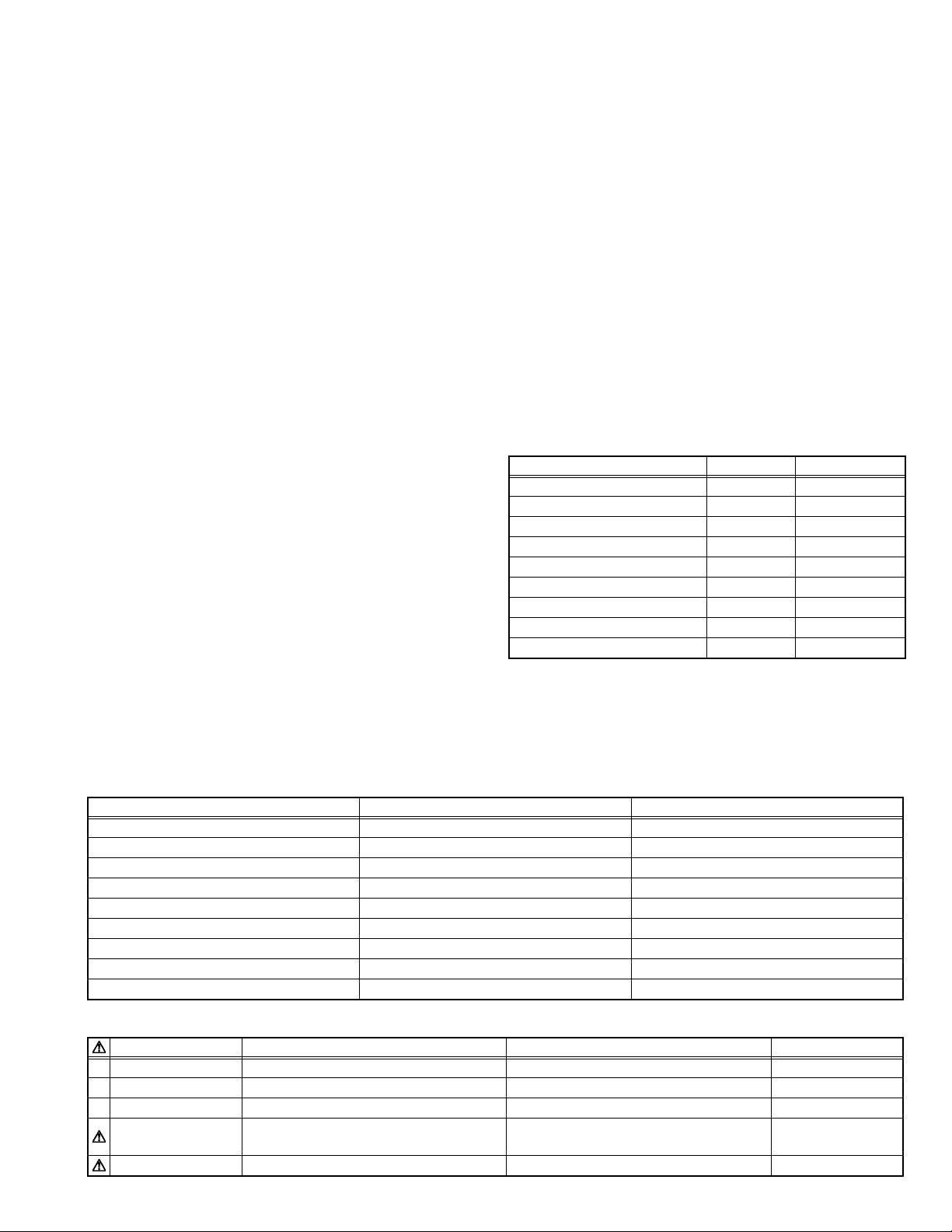
4.3 REQUIRED ADJUSTMENTS BY REPLACING COMPONENTS
The following adjustment procedure is required after replacing PWB ASS'Ys, LAMP BALLAST UNIT and OPTICAL BLOCK.
Items noted as "Check" means check the condition, then adjust if required.
4.3.1 Component required adjustment at replacing
Adjustment items MAIN TERMINAL DD SUB POWER
1. D-ILA COMMON DC Check Required Check Check Required
2. GAMMA (GRADATION / WHITE BALANCE) Check Required Check Check Required
3. SHADING (UNIFORMITY) Check Check Check Required
4. 8 - PHASE VERTICAL BARS Check Required Required
5. A-D CONVERTER APERTURE Required
6. COLOR TEMPERATURE Check Check Required
7. COLOR PROFILE Check Required
8. GHOST Check Required
9. FRAME Check Required
4.3.2 List of required instruments and tools (except those related to the personal computer)
LAMP
BALLAST
OPTICAL
BLOCK
Adjustment items
1. D-ILA COMMON DC Required (Required)
2. GAMMA (
3. SHADING (UNIFORMITY) Required Required Required
4. 8 - PHASE VERTICAL BARS Required Required
5. A-D CONVERTER APERTURE Required Required Required
6. COLOR TEMPERATURE Required Required
7. COLOR PROFILE Required Required
8. GHOST Required
9. FRAME Required
4.3.3 Data backup
Before replacing major components such as PWB ASS'Ys, UNIT or BLOCK, be sure to backup the data contained in the set.
In absence of data backup, complete adjustment becomes necessary.
z PREPARATION
(1) Make sure that Version.ini file is located in the same folder of the PSA controller.
(2) Remove all signal cables except for the interface cable to the PC from the main body.
z DATA SAVE
(1) Enter Stand-by mode and open the PSA controller on the PC.
(2) Click [System] in the main menu. When the pull down menu is displayed, click [Backup ROM Data] and open ROM Data Up
(3) Tick [Main EEPROM] and [Sub EEPROM] in [Target EEPROM].
(4) When [Down Load] is selected, data will be downloaded in the order of EEPROM → EEPROM2 → SUB EEPROM.
(5) When the download has completed, Save Data with File Name dialog box will be displayed. Then save the data with a file
z DATA ENTRY
(1) Enter Stand-by mode and open the PSA controller on the PC.
(2) Click [System] in the main menu. When the pull down menu is displayed, click [Backup ROM Data] and open ROM Data Up
(3) Tick [Main EEPROM] in [Target EEPROM].
(4) When [Down Load] is selected, Open dialog box will be displayed. Then select a file which you want to upload.
(5) The data will be downloaded in the order of EEPROM → EEPROM2 → SUB EEPROM.
GRADATION / WHITE BALANCE
Load/Down
Load.
name.
Load/Down Load.
OSCILLOSCOPE
) Required Required Required Required
PC signal
generator
NTSC
signal
generator
HDTV
signal
generator
Light meter Color filter Color meter
(No.PA018)1-21
Page 22

4.4 ADJUSTMENT PROCEDURE
4.4.1 D-ILA COMMON DC adjustment
Instruments REPLACING COMPONENTS
Test point
Adjustment menu < DDIC >
Preparation Running the unit enough before adjustment
Note :
Large deviation of this adjustment can cause image flicker.
Residual image or element burn can occur when out of adjustment.
WATCHING ADJUSTMENT
(1) Open Menu [DDIC] [Flat Field / DD Ctrl], and set [Dual Scan] to [Off].
(2) Set [R Mute], [G Mute] and [B Mute] to [On].
(3) Set [R] Flat Field level to 512, and set [G] and [B] Flat Field level to 0.
(4) Open Menu [DDIC] [EVR], then adjust [R Com] to minimize the flickers with watching. If there is unevenness with the flickers,
try to manage the balance of flickers by reducing the high-visibility portions of the flickers as much as possible.
Note :
Do not adjust under the lamp have flickers.
(5) Open Menu [DDIC] [Flat Field / DD Ctrl], and set block [R] Flat Field level to 0.
(6) Set [G] Flat Field level to 512.
(7) Open Menu [DDIC] [EVR], then adjust [G Com] to minimize the flickers with watching. If there is unevenness with the flickers,
try to manage the balance of flickers by reducing the high-visibility portions of the flickers as much as possible.
(8) Open Menu [DDIC] [Flat Field / DD Ctrl], and set block [G] Flat Field level to 0.
(9) Set [B] Flat Field level to 512.
(10) Open Menu [DDIC] [EVR], then adjust [B Com] to minimize the flickers with watching. If there is unevenness with the flickers,
try to manage the balance of flickers by reducing the high-visibility portions of the flickers as much as possible.
(11) Open Menu [DDIC] [Flat Field / DD Ctrl], and set block [B] Flat Field level to 0.
(12) When all of the adjustments are finished, set [R Mute] [G Mute] [B Mute] to [Off].
(13) Set [Dual Scan] to [On].
z DD SUB PWB ASS'Y
z OPTICAL BLOCK
1-22 (No.PA018)
Page 23

4.4.2 GAMMA adjustment
Instruments SVGA signal generator [Gray scale]
Light-meter
Color-meter (CL-200)
Color filter (R / G / B)
Test point
Adjustment menu < DDIC > < Gamma >
Preparation Completed D-ILA COMMON DC adjustment
PREPARATION
(1) Set to ZOOM at Wide end, if a zoom lens is installed.
(2) Measure the lightness in the room with a proofread light-meter and set the lightness to below 0.03lx.
(3) Set the light-meter on the center of image.
(The distance from the projection lens to the light-meter is approximate 30cm, then don't move them.)
(4) Open Menu [Gamma] and click [Default], then make sure that the Gamma line is linear. After a check, click the [Transmit] and
transmit data.
(5) Open Menu [DDIC] and set [LUMDAT] to [Off].
(6) Open Menu [DDIC] [Flat Field / DD Ctrl], and set [R Mute], [G Mute] and [B Mute] to [On].
(7) Allow the unit adequate time (more than 10 minutes) to warm-up.
(8) After installing the top cover, adjust the unit.
(9) Open Menu [User Adjust] [Image] tab, and set [Color Temp] to [6500K].
OFFSET GAIN ADJUSTMENT
(1) Set the G color filter in front of the light-meter, and measure the luminance of the center of the screen.
(2) Open Menu [DDIC] [EVR], then set [R OFFSET] and [B OFFSET] to 255. (Record the data before adjustment)
(3) Open Menu [DDIC] [Flat Field / DD Ctrl] and set [R], [G] and [B] Flat Field level to 0 similarly.
(4) Open Menu [DDIC] [EVR] and set [G OFFSET] to 255, then record the illumination intensity (the lowest illumination intensity)
at this time.
(5) Open Menu [DDIC] [Flat Field / DD Ctrl], and set [G] Flat Field level to 1023.
(6) Open Menu [DDIC] [EVR], and adjust [G OFFSET] so that the illumination intensity becomes the highest. Record the illumi-
nation intensity (the highest illumination intensity) at this time.
(7) The target of the 0 IRE adjustments should be the higher illumination intensity between the value 1 (1.05 times of the lowest
illumination intensity) and the value 2 (the highest illumination intensity × 0.95 / 1000).
(8) Open Menu [DDIC] [Flat Field / DD Ctrl], and set the Flat Field level of [G] to 64. Under this condition, open Menu [DDIC] [EVR]
and adjust [G OFFSET] so that the illumination intensity falls within the target value of the 0 IRE adjustments in 7) above.
(9) Open Menu [DDIC] [Flat Field / DD Ctrl],and set the Flat Field level of [G] to 960. At this time, click [Gain/Setup] of [Gain] and
adjust the illumination intensity with the cursor so that it becomes 95% of the highest illumination intensity.
(10) Repeat the adjustment so that the requirements in step 8) and 9) are met together.
(11) Adjust [R], [B] in the same way with [R], [B] color filter.
(12) Open Menu [DDIC] [Flat Field / DD Ctrl], and set the Flat Field level of [R], [G] and [B] to 960, respectively. Then measure the
uv value using a color-meter. If the uv value exceeds +0.025, open [Gain/Setup] and lower the [Gain] value so that the
uv value falls within +0.025. In case where the uv value is less than +0.025, no adjustment is required. (By clicking [ALL],
adjust the eight phases together.
G GAMMA & COMPUTATION OF ADJUSTMENT TARGET LUMINANCE
(1) Open Menu [Gamma] and set the control point to [VGP].
(2) Put [G] color filter in front of the light-meter and measure the illumination intensity at the center of the screen.
(3) Open Menu [DDIC] [Flat Field / DD Ctrl], and adjust the Flat field level of [G] to 960, [R] and [B] to 0. Then measure the 100
IRE illumination intensity of [G].
(4) Based on the calculating table for target illumination intensity and the measurement results obtained in 3) above, calculate the
target illumination intensity of the control points 14-2.
(5) By adjusting the Flat Field level of each control point, adjust the illumination intensity of the screen so that it falls within the
values calculated in accordance with the calculating table.
REPLACING COMPONENTS
z DD SUB PWB ASS'Y
z OPTICAL BLOCK
(No.PA018)1-23
Page 24

< ADJUSTMENT TARGET ILLUMINATION TABLE >
Control point FLAT FIELD ADJUSTMENT TARGET
coefficient
14 896 0.850 92.86
13 800 0.649 82.14
12 704 0.477 71.43
11 608 0.334 60.71
10 512 0.218 50.00
9 416 0.128 39.29
8 320 0.064 28.57
7 256 0.034 21.43
6 224 0.023 17.86
5 192 0.0151 14.29
4 160 0.0096 10.71
3 128 0.0056 7.14
2 96 0.00280 3.57
< The computation type >
• ADJUSTMENT TARGET ILLUMINANCE = 100 IRE ILLUMINANCE × ADJUSTMENT TARGET coefficient
• 0 IRE ILLUMINANCE = MAXIMUM ILLUMINANCE × 0.95 / 1000 or 1.05 times of the lowest illumination intensity
R and B GAMMA ADJUSTMENT
(1) Set the color-meter at the center of the screen.
(2) Open Menu [DDIC] [Flat Field / DD Ctrl], then set [R], [G] and [B] Flat Field level to 960, respectively. Then record the points
of chromaticity (X, Y) at this time.
(3) Open Menu [DDIC] [Flat Field / DD Ctrl] and adjust [R], [G] and [B] Flat Field level to the value as shown in the control point
14 in the calculating table for target illumination intensity.
(4) Open Menu [Gamma]. Then click [Option] at the lower right of the Gamma screen to display the sub-screen.
(5) Then adjust the gamma adjustment point 14 of [R] and [B] so that the points of chromaticity become the values measured in
2) above. (In case where you choose the Flat Field level of [R] and [B] in the sub-screen, click [R] and [B] at the higher right
on the screen, respectively.)
(6) Adjust the control point 13~2 like above 5).
(7) If the gamma at the control points 2 and 3 show discontinuous curve or the target points of chromaticity cannot be obtained,
adjust the curve as if it looks like a smooth curve visibly.
(8) Repeat the adjustment until all of the control points obtain the requirements together.
SIGNAL LEVEL
1-24 (No.PA018)
Page 25

4.4.3 SHADING adjustment
Instruments SVGA signal generator
Light-meter
Test point
Adjustment menu < DDIC > < Area Shading >
Preparation Completed GAMMA adjustment
REPLACING COMPONENTS
z DD SUB PWB ASS'Y
z OPTICAL BLOCK
PREPARATION
(1) When the reverse shading function is used, open Menu
[DDIC] [Flat Field / DD Ctrl], and set [Left side Right] and
[Up Side Down] to [Off].
(2) Open Menu [Area Shading] and, after clicking [LUM]. Set
each [R], [G] and [B] to [Default] respectively, then click
[Transmit].
(3) Click [DYN] or [STC] and set [R], [G] and [B] to [Default]
respectively in the same way, then click [Transmit].
SHADING ADJUSTMENT
(1) Open Menu [DDIC] [Flat Field / DD Ctrl], and set [R
Mute], [G Mute] and [B Mute] to [On].
(2) Set [R], [G] and [B] Flat Field level to 204, respectively.
(3) Open Menu [Area Shading] and click [STC]. Then adjust
the screen with the slide bar for adjustment level setting
so that the screen is evenly colored.
(4) Open Menu [DDIC] [Flat Field / DD Ctrl] and set [R], [G]
and [B] Flat Field level to 614, respectively.
(5) Open Menu [Area Shading] and click [DYN]. Then adjust
the screen with the slide bar for adjustment level setting
so that the screen is evenly colored.
(6) Open Menu [DDIC], and set [DYNDAT] [STCDAT] to
[Off].
(7) Open Menu [Flat Field / DD Ctrl] and set [R] Flat Field
level to 204, [G] and [B] Flat Field level to 0, respectively.
Record the brightness of the screen at this time
(8) Set [R] Flat Field to 614 and record the brightness of the
screen at this time.
(9) Return [DYNDAT] and [STCDAT] to [On].
(10) Open Menu [EVR] and adjust [R OFFSET] so that the
brightness of the screen become the same value as
those of the recorded value.
(11) Open Menu [DDIC] [Gain/Setup] and click [Gain]. Adjust
[DDIC] [GAIN] so that the brightness of the screen at the
[R] Flat Field level of 614 become the same value re-
corded in 8) above.
(12) In the same manner as for the above steps, also adjust
[G] and [B] Flat Field level.
(13) Adjust [LUM], if necessary. Keep the Flat Field level at
1023 at the center of the screen as much as you can.
(14) After adjustment, transfer the data to the reverse shad-
ing adjustment memory by clicking [Copy Shading Data
to Reverse Shading Data] on the bottom of the Area
Shading screen. At this time, open [Shading] on [Config-
uration] tool bar and set the values according to the table
on the right side so as to compensate the vertical reverse
shading gradient.
∗If necessary, adjust Up Side Down position. When adjusting
the Up Side Down position, hang the unit from the ceiling.
Open Menu [DDIC] [Flat Field DD/Ctrl] and set [Left Side
Right] and [Up Side Down] to [On]. For the adjustment, follow
the same manner as for the steps 1)~14) above.
LUM DYN STC Vcom
R G B
button
button
Default
button
<Area Shading> Menu
[Offset] : Presetting
[Copy Shading Data to Reverse Shading Data] :
Revers shading adjustment memory setting
[Cursor size] : Adjustment area setting
[Slide bar] : Adjustment level setting
STC Shading DYN Shading
Red 63 0.1
Green 63 0.1
Blue 63 0.1
< Compensate the vertical reverse shading gradient >
(No.PA018)1-25
Page 26

4.4.4 8-PHASE VERTICAL BARS adjustment
Instruments Oscilloscope
Light-meter (Analog output terminal)
Test point
REPLACING COMPONENTS
z OPTICAL BLOCK
z DD SUB PWB ASS'Y
Adjustment menu < DDIC >
Preparation Completed GAMMA adjustment
DC SETUP ADJUSTMENT
[ Method of signal waveform observation ]
(1) Open Menu [DDIC] [EVR] and save the data at [EVR R OFFSET], then set the value to 255. Turn [DCS DAT] on the right
of [EVR] to [ON].
(2) Open Menu [Flat Field / DD Ctrl] and, after turning [R MUTE] to [ON], set [R] Flat Field level to zero.
(3) Connect an oscilloscope to the TEST PIN (See the table given below) on the DD SUB PWB, observe the DC level of the 0-
PHASE signal through seven phase signal. Then record the target value for adjustment which shall be an approximate in-
termediate value between the maximum and minimum of the DC level.
(4) Open Menu [DDIC] [Gain/Setup] and click [DC Setup]. Observe the DC level of the 0-PHASE signal and adjust [DC Setup]
for the 0-PHASE of [DDIC] [Gain/Setup] so that the DC level of the 0-PHASE signal falls within the target value recorded in
3) above.
Note :
Click [Separate A and B], then adjust [A-line] and [B-line], respectively. When the A-line is made larger, the DC level increases. On the other hand, when the B-line is made larger, the DC level decreases. Either A-line or B-line or both should
be 0.
(5) In the same manner as for above, adjust the 1-PHASE to 7-PHASE.
(6) Return [EVR] [R OFFSET] to its original value recorded in 1) above.
(7) Also adjust [G] and [B] in the same manner as for the steps 1) - 5) above.
Test pin for observation of DD SUB PWB
RGB
0-PHASE TP 101 TP 201 TP 301
1-PHASE TP 102 TP 202 TP 302
2-PHASE TP 103 TP 203 TP 303
3-PHASE TP 104 TP 204 TP 304
4-PHASE TP 105 TP 205 TP 305
5-PHASE TP 106 TP 206 TP 306
6-PHASE TP 107 TP 207 TP 307
7-PHASE TP 108 TP 208 TP 308
TOP
1-26 (No.PA018)
DD SUB PWB TEST POINT LOCATION
CN800
CN801
DD SUB PWB
CN301
TP308
TP304
TP307
TP303
TP306
TP305
TP302
TP301
CN101
CN201
CN899
TP206
TP203
TP108
TP105
TP102
TP207
TP204
TP201
TP106
TP103
TP101
TP208
TP205
TP202
TP107
TP104
Page 27

[ Method using light-meter ]
(1) Adjust [V-COM] again.
(2) Set a light-meter with analog output terminal at the screen center and observe waveform of the analog output using an os-
cilloscope.
(3) Open Menu [DDIC] [Flat Field / DD Ctrl], and turn [R Mute], [G Mute], [B Mute] to [On].
(4) Open Menu [Gain/Setup] and click [Gain]. Record the data of [R], [G] and [B] at this time.
(5) Set all phases of [R], [G] and [B] of [Gain] to 0.
(6) Open Menu [Flat Field / DD Ctrl] and set [R] Flat Field level to 500, then [G] and [B] to 0, respectively.
(7) Open Menu [Gain/Setup] and click [Gain]. Return the 0-PHASE of [Gain] to the data recorded in 4) above.
(8) Click [DC Setup]. Using an oscilloscope, observe the waveform of the flicker. Then adjust the 0-PHASE so that the ampli-
tude of the flicker is reduced to a minimum.
(9) Click [GAIN] and set the 0-PHASE to 0.
(10) In the same manner as for above, adjust 1-PHASE to 7-PHASE.
(11) In the same manner as for the steps 6)-10) above, adjust [G] and [B].
(12) Open [DDIC] [GAIN] and return the value of [GAIN] to the value recorded in 4) above.
(13) Adjust V-COM again.
G BLACK 8 BARS ADJUSTMENT
(1) Supply a G gray-scale signal.
(2) Open Menu [DDIC] [Gain/Setup], then click [G] and [Setup].
(3) Observe the darkest gradation with vertical stripes and the lighter portions (1-2 lighter gradations) from the darkest gradation.
Then adjust the phase with the adjustment cursor so that the vertical stripes are reduced to a minimum. (Adjust each phase
separately after turning [ALL] off.)
Note :
Set [Separate A and B] to off, then adjust [A-line] and [B-line] at the same time.
G WHITE 8 BARS ADJUSTMENT
(1) Supply a G gray-scale signal.
(2) Open Menu [DDIC] [Gain/Setup], then click [G] and [Gain].
(3) Observe the lightest gradation with vertical stripes and the darker portions (1-2 darker gradations) from the lightest gradation.
Then adjust the phase with the adjustment cursor so that the vertical stripes are reduced to a minimum. (Adjust each phase
separately after turning [ALL] off.)
Note :
Set [Separate A and B] to off, then adjust [A-line] and [B-line] at the same time.
R ADJUSTMENT
(1) In the same manner as for G Black 8 bars and G white 8 bars adjustments, adjust R.
B ADJUSTMENT
(1) In the same manner as for G Black 8 bars and G white 8 bars adjustments, adjust B.
(No.PA018)1-27
Page 28

4.4.5 A-D CONVERTER APERTURE adjustment
Instruments SVGA signal generator [Gray scale (include : white100% & black 0%)]
NTSC signal generator
HDTV signal generator color-meter
Test point
Adjustment menu < User Adjustment >
Preparation
ADJUSTMENT OF RGB SYSTEM
(1) Open Menu [Gamma] and click [Receive], then perform
asking of the Gamma data.
(2) Open Main screen of PSA controller. Save the data by
[File] → [Save].
(3) Open Menu [Gamma] and set the control point to [128
Points].
(4) Select the Point No.8, and set Y Position to 2047.
(5) Select the Point No.120, and set Y Position to 2047.
(6) Supply a SVGA 0% signal from the D-SUB terminal.
(7) Open Menu [User Adjust] [Adjustment] and adjust [Sub-
BRT G] so that the screen becomes brightest.
(8) Supply SVGA green 100% luster signal from D-SUB ter-
minal.
(9) Open Menu [User Adjust] [Adjustment] and adjust [Sub-
CNT G] so that the screen becomes darkest.
(10) Return the value of the Gamma carve to the value saved
in (2) above.
(11) Adjust [R] and [B] according to the same order of (1)-(7)
above.
REPLACING COMPONENTS
z MAIN PWB ASS'Y
ADJUSTMENT OF COMPONENT (COLOR DIFFERENCE) SYSTEM
• Please carry out this adjustment after completing the adjustment of RGB system.
[ Watching adjustment ]
(1) Supply a component gray scale signal of NTSC.
(2) Open Menu [User Adjust] [Adjustment] and adjust [Cb
Offset] and [Cr Offset] so that the white balance at the
dark gradation becomes same gradation as those at
the screen center.
(3) Supply a component gray scale signal of HDTV.
(4) Open Menu [User Adjust] [Adjustment] and adjust [Cb
Offset] and [Cr Offset] so that the white balance at the
dark gradation becomes same gradation as those at
the screen center.
[ Adjustment by the color meter ]
(1) Open Menu [DDIC] [Flat Field / DD Ctrl] and set [R
Mute], [G Mute] and [B Mute] to [On].
(2) Set [R], [G] and [B] Flat Field level to 154 and measure
the color point of the screen center, then record the
value.
(3) Supply a component white 10% flat signal of NTSC
from the component terminal.
(4) Measure the color point of the screen center.
(5) Open Menu [User Adjust] [Adjustment] and adjust [Cb
Offset] and [Cr Offset] so that the color point becomes
the same as measured in (4) above.
(6) Supply a component gray scale signal of HDTV.
(7) Measure the color point of the screen center.
(8) Open Menu [User Adjust] [Adjustment] and adjust [Cb
Offset] and [Cr Offset] so that the color point becomes
the same as measured in (7) above.
(9) Open Menu [DDIC] [Flat Field / DD Ctrl], then set [R
Mute], [G Mute] and [B Mute] to [Off].
Sub-CNT R / G / B
Sub-BRT R / G / B
Cr Offset / Cb Offset Adjustment
User Adjust MENU
1-28 (No.PA018)
Page 29

4.4.6 COLOR TEMPERATURE adjustment
Instruments SVGA signal generator
Color-meter (CL-200)
Test point
Adjustment menu < User adjust >
Preparation Completed GAMMA adjustment , SHADING adjustment ,
A-D CONVERTER APERTURE adjustment
• Open Menu [User Adjust], and set [Color Temp] to 6500K after set the initial value of [R-Temp] [G-Temp] and [B-Temp] to 0.
(1) Supply a white 50% signal of SVGA.
(2) Adjust [G-Temp] so that the deviation [duv] at the screen center falls within +0.01±0.001.
(3) After adjustment in (3) above, check the color temperature at the screen center. If the temperature is more than 6500K, adjust
[B-Temp] so that it falls within 6500K±100K. At the same time, adjust [G-Temp] so that the deviation [duv] falls within
+0.01±0.001.
* At this time, set [R-Temp] to 0.
(4) After adjustment in (3) above, check the color temperature at the screen center. If the temperature is less than 6500K, adjust
[R-Temp] so that it falls within 6500K±100K. At the same time, adjust [G-Temp] so that the deviation [duv] falls within
+0.01±0.001.
* At this time, set [B-Temp] to 0.
4.4.7 COLOR PROFILE adjustment
Instruments SVGA signal generator (include : white 505)
Color-meter (CL-200)
Test point
Adjustment menu < CMS >
Preparation Completed GAMMA adjustment , SHADING adjustment
A-D CONVERTER APERTURE adjustment,
COLOR TEMPERATURE adjustment
REPLACING COMPONENTS
z OPTICAL BLOCK
REPLACING COMPONENTS
z OPTICAL BLOCK
PREPARATION
(1) Open Menu [CMS].
(2) Prepare COLOR PROFILE DATA (acr_r, acr_g, acr_b).
(3) Install a color-meter.
ADJUSTMENT OF COLOR PROFILE
(1) Open Menu [CMS] and select [ACR] tab at the lower part of [CMS Control] screen.
(2) Select [sRGB] tab located on the third column from the top of the screen.
(3) Click [sRGB] button located on the second column from the top of the screen and enter [sRGB] operation mode.
(4) Supply a R 50% raster signal of SVGA.
(5) Click [R] button on the left column of the data sheet of [CMS Control] screen.
(6) Using the color-meter, carry out the ACR adjustment so that the color temperature at the center of the projected screen be-
come x=0.640±0.03 and y=0.330±0.03.
Method of ACR adjustment :
By pressing [Load] button, select the necessary data from the acr_r-30~acr_r+30 in the color profile data provided. Then
push [Transmit] button to transfer the date to the projector. By repeating the steps above, adjust the ACR so that it falls
within the standard values. Repeat the steps above until the specified values can be obtained.
(7) Supply a G 50% raster signal of SVGA.
(8) Click [G] button on the left column of the data sheet of [CMS Control] screen.
(9) Using the color-meter, carry out the ACR adjustment so that the color temperature at the center of the projected screen be-
come x=0.300±0.03 and y=0.600±0.03.
Method of ACR adjustment :
By pressing [Load] button, select the necessary data from the acr_g-30~acr_g+30 in the color profile data provided. Then
push [Transmit] button to transfer the date to the projector. By repeating the steps above, adjust the ACR so that it falls
within the standard values. Repeat the steps above until the specified values can be obtained.
(10) Supply a B 50% raster signal of SVGA.
(11) Click [B] button on the left column of the data sheet of [CMS Control] screen.
(No.PA018)1-29
Page 30

(12) Using the color-meter, carry out the ACR adjustment so that the color temperature at the center of the projected screen be-
come x=0.150±0.03 and y=0.060±0.03.
Method of ACR adjustment :
By pressing [Load] button, select the necessary data from the acr_b-30~acr_b+30 in the color profile data provided. Then
push [Transmit] button to transfer the date to the projector. By repeating the steps above, adjust the ACR so that it falls
within the standard values. Repeat the steps above until the specified values can be obtained.
(13) Select [Apple] button located on the second column from the top of the screen and [Apple] tab on the third column from the
top of the screen, then enter [MACRGB] operation mode of CSP.
(14) In the same manner as for 4) to 12) above, adjust ARC so that the values fall within the specified values given below.
(15) Select [Adobe] button located on the second column from the top of the screen and [Apple] tab on the third column from the
top of the screen, then enter [Adobe] operation mode of CSP.
(16) In the same manner as for 4) to 12) above, adjust ARC so that the values fall within the specified values given below.
(17) Select [EBU] button located on the second column from the top of the screen, and [Apple] tab on the third column from the top
of the screen, then enter [EBU] operation mode of CSP.
(18) In the same manner as for 4) to 12) above, adjust ARC so that the values fall within the specified values given below.
(19) Press [OFF], [SRGB], [EBU], [Apple] and [Adobe] located on the second columnfrom the top of the screen in turn and confirm
that the picture quality (gamma and color) on the screen changes.
OPERATION MODE Color
1
2
3
4
SRGB
(HDTV)
MACRGB
(LCD)
Adobe RGB
(NTSC)
EBU
(PAL)
R0.640.33
B0.150.06
R0.640.34
B 0.155 0.07
R0.630.34
B 0.155 0.07
R0.640.33
B0.150.06
xyTolerance
Specified value
x,y=±0.03G0.30.6
x,y=±0.03G 0.3 0.59
x,y=±0.03G 0.31 0.595
x,y=±0.03G 0.29 0.6
4.4.8 GHOST adjustment
Instruments Signal generator REPLACING COMPONENTS
Test point
Adjustment menu < DDIC >
Preparation Completed GAMMA adjustment , SHADING adjustment ,
A-D CONVERTER APERTURE adjustment
(1) Input a picture included letter signal.
(2) Open [DDIC] and click [EVR] tab.
(3) Adjust [CLK SHIFT] so that the ghost is reduced to a minimum.
4.4.9 FRAME adjustment
Instruments Signal generator REPLACING COMPONENTS
Test point
Adjustment menu < DDIC >
Preparation Completed GAMMA adjustment , SHADING adjustment ,
A-D CONVERTER APERTURE adjustment
(1) Supply an all black signal.
(2) Open [DDIC] and click [EVR] tab.
(3) Adjust [R FRAME], [G FRAME] and [B FRAME] so that the picture frame floating is not visible significantly on the screen.
z OPTICAL BLOCK
z OPTICAL BLOCK
1-30 (No.PA018)
Page 31

SECTION 5
TROUBLESHOOTING
5.1 PROTECTIVE SENSOR AND PROTECTIVE SWITCH
In event of abnormal operation due to circuit or component failure, setting error or other reason, in order to prevent serious damage
to the set and preserve the integrity of peripheral equipment, sensors and switches are provided for protective functions. Cooling is
conducted at the same time a corresponding LED flashes (about 90 seconds). The LED indication with respect to the protective function is described below.
5.1.1 Protective sensor
Type Monitor objective Location Operating point Function
Thermal sensor
(Thermostat)
Thermal sensor (IC) Set interior
Thermal sensor (IC) Set exterior
Motor operation
detection circuit
5.1.2 Protective switch
Type Monitor objective Location Operating point Function
Interlock switch Lamp cover Optical block (Lamp section) Switch open Control by CPU
Lamp unit Optical block (Lamp section) 140°C AC line (one side) open
MAIN PWB ASS'Y IC728 70°C Power off by main CPU (emergency mode)
(Lamp area)
MAIN PWB ASS'Y IC727 62°C Power off by main CPU (emergency mode)
(Filter area)
Cooling fan Cooling fan interior Fan stop Power off by main CPU (emergency mode)
5.2 LED (INDICATOR) WARNING INDICATIONS
5.2.1 Led indication contents
If an abnormality occurs during operation (projection), the content of the problem can be determined from flashing LED indicators.
When an LED indicates, operation (projection) automatically stops and the cool-down mode (about 90 seconds) is entered (except for
No.1, No.3, No.4, No.5 and No.6), then the stand-by mode.
No. Flashing LED Flash time Warning cause (projector mode)
LAMP TEMP STAND BY OPERATE
1 zz0.5sec. Lamp not lighted cannot project
2 zz0.5sec.
3 ××0.5sec. Lamp terminal not contact
4 zz 0.5sec. Sub CPU circuit error
5 zz 0.25sec. Device drive circuit error
6 ×× 0.5sec. Video process circuit (decoder) error
7 ×× 0.25sec. Video system error after data initializing
8 z 0.5sec. Set interior abnormally hot
9 zz 0.5sec.
10 zzzz0.5sec. Set internal cooling fan stopped (fan locked)
11 z 0.5sec. Lamp use time exceeds 2000 hours
z : Flashing together × : Flashing alternately
Lamp extinguishes during projection Lamp use time exceeds 2010 hours
Air intake temperature too high (exterior temperature
abnormal)
(No.PA018)1-31
Page 32

5.2.2 Mearsures during abnormality
In event of the following be sure to disconnect the power cord from the AC outlet, and reset the projector mode.
No. Abnormality Mode Measure Mode Cause
1 Lamp dose not light → Again supply power (press OPERATE button) OK Lamp lighting failure
NG Check lamp use dose not exceed 2000 hours YES Lamp use inhibited
NG Replace lamp unit OK Lamp defective
NG Replace LAMP BALLAST unit OK Igniter circuit faulty
2 Lamp extinguishes during
projection
Lamp use time exceeded → Replace lamp and reset the lamp use time OK Lamp use inhibited
3 Sub CPU operation faulty → Again supply power (press MAIN POWER
4 DD circuit operating faulty → Again supply power (press OPERATE button) OK Circuit operating error
5 Decoder operation faulty → Again supply power (press OPERATE button) OK Circuit operating error
6 Video system data
initializing error
7 Internal temperature
abnormally high
8 Out side temperature
abnormally high
9 Cooling fan stopped → Reinstall 713 connector OK Connector installation defective
10 Confirmation of DVI
activation
→ Revise installation mode (protect from shock,
vibration, etc)
NG Replace lamp unit OK Lamp defective
button)
NG Replace MAIN PWB ASS'Y OK Sub CPU failure
NG Replace MAIN PWB ASS'Y OK Device drive circuit failure
NG Replace MAIN PWB ASS'Y OK Video process circuit failure
→ Again supply power (press OPERATE button) OK Operating (loading) error
→ Avoid obstructing ventilation openings (intake
and exhaust)
NG Replace MAIN PWB ASS'Y OK Defective sensor and detection circuit
→ Ambient temperature of the unit should be
mode into specification within the limits
NG Replace MAIN PWB ASS'Y OK Defective sensor and detection circuit
NG Reinstall 705 connector OK Connector installation defective
NG Reinstall 706 connector OK Connector installation defective
NG Reinstall 707 connector OK Connector installation defective
NG Reinstall 714 connector OK Connector installation defective
NG Replace cooling fan OK Cooling fan defective
→ Temporarily disconnect power from projector
and PC. After making sure that DVI cable has
been properly connected, turn on power of
projector and PC, in turn.
NG Confirm that output of DVI terminal at graphic
board of PC has been set properly.
OK Installation mode (environment)
unfavorable
OK Circuit operating error
OK Circuit error or other fault
OK Circuit error or other fault
OK Improper connection of DVI cable
Wrong order of power on (Correct
order : 1. Projector 2. PC )
OK Improper setting of PC (DIV output)
1-32 (No.PA018)
Page 33

5.3 ERROR LOG (SELF-DIAGONOSIS RECORD AND INDICATION)
5.3.1 Outline
By using the special setting and adjustment software, data related to abnormal operation (history) stored in the projector can be load.
On the basis of contents "LED (INDICATOR) WARNING INDICATONS" set and lamp use time, internal and external temperature, and
other data prior to the previous usage time can be viewed as a table.
z HOW TO LOAD THE DATA FROM UNIT
(1) Install the software in a personal computer and connect
by RS-232C IN terminal (use cross cable).
(2) Set the projector to stand-by mode.
(3) Start the setting and adjustment software. The main
menu shown in Fig.1 appears.
(4) Click the [Error Log] button to show the screen indicated
in Fig.2.
(5) Click the [Receive Log Data] button to display the history.
z ERROR LOG SCREEN ITEMS
Item Displayed contents
Error Detection Error event code (10 types)
Wakeup Count Number of times operation mode reached
System Time Total time in operation mode until present
Lamp Time Total lamp lighted time until present
Slave Deg (Out) External temperature detected by sensor dur-
ing error event
Sub Deg (In) Internal temperature detected by sensor dur-
ing error event
Click
Fig.1 Start screen (main menu)
5.3.2 Error code
Error cord Detected condition Indicated LED
E01 Lamp can not light during shift from stand-by to operation mode STAND BY + LAMP (Blinking)
E02 Lamp use time exceeds 2000h LAMP (Blinking)
E03 Inter IC bus communication error (ACK receive error) Absent
E06 Lamp extinguishes during projection OPERATE + LAMP (Blinking)
E07 Cooling fan stops (fan lock) All (4 LEDs Blinking)
E08 Set internal temperature (lamp area) abnormally high (Exceeds 70°C) TEMP (Blinking)
E09 Set internal temperature (ventilation intake openings) abnormally high (Exceeds 62°C) STAND BY + TEMP (Blinking)
E10 Lamp use time exceeds 1900h LAMP(Light on)
E11 Error in device drive circuit operation LAMP + TEMP (Blinking)
E15 Come off lamp cover OPERATE + LAMP
5.3.3 Function
Button (item) Function Data process
Receive Receive data stored in projector and display < Error log > screen Projector to PC
Reset Delete all data stored in projector (reset) Projector internal
Clear Display Delete record (history) shown on < Error log > screen (delete computer side) PC internal
Save Save record (history) shown on < Error log > screen to file PC internal
Load Read record (history) stored in PC and display in < Error log > screen PC internal
Fig.2 <Error log> screen
(Alternately blinking)
(No.PA018)1-33
Page 34

VICTOR COMPANY OF JAPAN, LIMITED
ILA CENTER 12, 3-chome, Moriya-cho, kanagawa-ku, Yokohama, kanagawa-prefecture, 221-8528, Japan
(No.PA018)
Printed in Japan
WPC
 Loading...