

Page 1
For Customer use :
Enter below the serial No. which is
located on the side of the cabinet.
Retain this information for future
reference.
Model No.
DLA-HD950
DLA-HD990
Serial No.
ENGLISH FRANÇAIS ESPAÑOL/CASTELLANO
0809TTH-AO-AO
© 2009 Victor Company of Japan, Limited
DLA-HD950
DLA-HD990
D-ILA PROJECTOR
PROYECTOR D-ILA
PROJECTEUR D-ILA
FOR SERVICING(Only in U.S.A)
TO OUR VALUED CUSTOMER
THANK YOU FOR PURCHASING THIS JVC PRODUCT.
WE WANT TO HELP YOU ACHINEVE A PERFECT EXPERINCE.
NEED HELP ON HOW TO HOOK UP?
NEED ASSISTANCE ON HOW TO OPERATE?
NEED TO LOCATE A JVC SERVICE CENTER?
LIKE TO PURCHACE ACCESSORIES?
IS HERE TO HELP!
TOLL FREE: 1(800)252-5722
http://www.jvc.com
Remember to retain your Bill of Sale for Warranty Service.
DO not attempt to service the product yourself
Caution
To prevent electrical shock,do not open the cabinet.
There are no user serviceable parts inside.
Please refer to qualified service personnel for repairs.
DLA-HD950/DLA-HD990
INSTRUCTIONS
MANUEL D’INSTRUCTIONS
MANUAL DE INSTRUCCIONES
D-ILA PROJECTOR
PROJECTEUR D-ILA
PROYECTOR D-ILA
DLA-HD950/DLA-HD990
Getting Started
Preparation
Basic Operation
Pour utilisation par le client :
Entrer ci-dessous le N° de série qui
est situé sous le boîtier. Garder
cette information comme référence
pour le futur.
N° de modèle
N° de série
DLA-HD950
DLA-HD990
Instrucción para el cliente :
Introduzca a continuación el nº de
serie que aparece en la parte
inferior lateral de la caja. Conserve
esta información como referencia
para uso ulterior.
Modelo Nº
Nº de serie
DLA-HD950
DLA-HD990
PC007182399-1
Settings
Troubleshooting
Others
Page 2
1
-
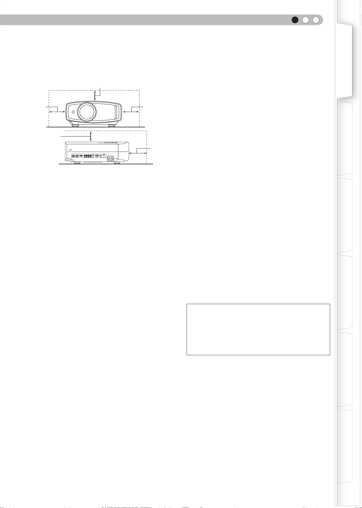
To allow better heat dissipation, keep a clearance between
this unit and its surrounding as shown below. When this
unit is enclosed in a space of dimensions as shown below,
use an air-conditioner so that the internal and external
temperatures are the same. Overheating can cause
damage.
-
the type of power supply to your home, consult your
product dealer or local power company.
- This product is equipped with a three-wire plug. This plug
will fit only into a grounded power outlet. If you are unable
to insert the plug into the outlet, contact your electrician to
install the proper outlet. Do not defeat the safety purpose
of the grounded plug.
- Power-supply cords should be routed so that they are not
likely to be walked on or pinched by items placed upon or
against them. Pay particular attention to cords at doors,
plugs, receptacles, and the point where they exit from the
product.
- For added protection of this product during a lightning
storm, or when it is left unattended and unused for long
periods of time, unplug it from the wall outlet and
disconnect the cable system. This will prevent damage to
the product due to lightning and power line surges.
- Do not overload wall outlets, extension cords, or
convenience receptacles on other equipment as this can
result in a risk of fire or electric shock.
- Never push objects of any kind into this product through
openings as they may touch dangerous voltage points or
short out parts that could result in a fire or electric shock.
Never spill liquid of any kind on the product.
- Do not attempt to service this product yourself as opening
or removing covers may expose you to dangerous
voltages and other hazards. Refer all service to qualified
service personnel.
-
Unplug this product from the wall outlet and refer service to
qualified service personnel under the following conditions:
a) When the power supply cord or plug is damaged.
b) If liquid has been spilled, or objects have fallen on the product.
c) If the product has been exposed to rain or water.
d) If the product does not operate normally by following the
operating instructions. Adjust only those controls that are
covered by the Operation Manual, as an improper adjustment
of controls may result in damage and will often require
extensive work by a qualified technician to restore the product
to normal operation.
e) If the product has been dropped or damaged in any way.
f) When the product exhibits a distinct change in performance -
this indicates a need for service.
- When replacement parts are required, be sure the service
technician has used replacement parts specified by the
manufacturer or with same characteristics as the original
part. Unauthorized substitutions may result in fire, electric
shock, or other hazards.
-
Upon completion of any service or repairs to this product,
ask the service technician to perform safety checks to
determine that the product is in proper operating condition.
- The product should be placed more than one foot away
from heat sources such as radiators, heat registers,
stoves, and other products (including amplifiers) that
produce heat.
- When connecting other products such as VCR’s, and DVD
player
s, you should turn off the power of this product for
protection against electric shock.
- Do not place combustibles behind the cooling fan. For
example, cloth, paper, matches, aerosol cans or gas
lighters that present special hazards when over heated.
- Do not look into the projection lens while the illumination
lamp is turned on. Exposure of your eyes to the strong
light can result in impaired eyesight.
- Do not look into the inside of this unit through vents
(ventilation holes), etc. Do not look at the illumination lamp
directly by opening the cabinet while the illumination lamp
is turned on. The illumination lamp also contains ultraviolet
rays and the light is so powerful that your eyesight can be
impaired.
- Do not drop, hit, or damage the light-source lamp (lamp
unit) in any way. It may cause the light-source lamp to
break and lead to injuries. Do not use a damaged light
source lamp. If the light-source lamp is broken, ask your
dealer to repair it. Fragments from a broken light-source
lamp may cause injuries.
- The light-source lamp used in this projector is a high
pressure mercury lamp. Be careful when disposing of the
light-source lamp. If anything is unclear, please consult
your dealer.
- Do not ceiling-mount the projector to a place which tends
to vibrate; otherwise, the attaching fixture of the projector
could be broken by the vibration, possibly causing it to fall
or overturn, which could lead to personal injury.
- Use only the accessory cord designed for this product to
prevent shock.
*DO NOT allow any unqualified person to install the
unit.
Be sure to ask your dealer to install the unit (e.g.
attaching it to the ceiling) since special technical
knowledge and skills are required for installation. If
installation is performed by an unqualified person, it
may cause personal injury or electrical shock.
power source indicated on the label. If you are not sure of
150 mm
and above
150 mm and above
300 mm
and above
200 mm
and above
300 mm
and above
SYNC
or similar surface. It should not be placed in a built-in installation
Safety Precautions
Safety Precautions
IMPORTANT INFORMATION
Th is p ro du ct h as a H ig h In te ns it y
Discharge (HID) lamp that contains
mercur
Disposal of these materials may be
regulated in your community due to
Getting started
y.
environmental consideratio ns. For
disposal or recycling information, please
contact your local authorities or for USA,
the Electronic Industries Alliance:
http://www.eiae.org.
WARNING:
TO PREVENT FIRE OR SHOCK HAZARDS, DO NOT
EXPOSE THIS APPLIANCE TO RAIN OR MOISTURE.
WARNING:
THIS APPARATUS MUST BE EARTHED.
CAUTION:
To reduce the risk of electric shock, do not remove cover.
Refer servicing to qualified service personnel.
This projector is equipped with a 3-blade grounding
type plug to satisfy FCC rule. If you are unable to insert
the plug into the outlet, contact your electrician.
FCC INFORMATION (U.S.A. only)
CAUTION:
Changes or modification not approved by JVC could
void the user’s authority to operate the equipment.
NOTE:
This equipment has been tested and found to comply
with the limits for Class B digital devices, pursuant to
Part 15 of the FCC Rules. These limits are designed to
prov id e r e as on a bl e p ro t ec t io n a ga in s t h ar mf u l
interference in a residential installation. This equipment
generates, uses, and can radiate radio frequency energy
and, if not installed and used in accordance with the
instructions, may cause harmful interference to radio
communications. However, there is no guarantee that
interference will not occur in a particular installation.
If this equipment does cause harmful interference to
radio or television reception, which can be determined
by turning the equipment off and on, the user is encourage
to try to correct the interference by one or more of the
following measures:
● Reorient or relocate the receiving antenna.
● Increase the separation between the equipment and
receiver.
● Connect the equipment into an outlet on a circuit different
from that to which the receiver is connected.
● Consult the dealer or an experienced radio/TV technician
for help.
2
MACHINE NOISE INFORMATION (Germany only)
Changes Machine Noise Information Ordinance 3. GSGV,
January 18, 1991: The sound pressure level at the operator
position is equal or less than 20 dB (A) according to
ISO 7779.
About the installation place
Do not install the projector in a place that cannot support
its weight securely.
If the installation place is not sturdy enough, the projector
could fall or overturn, possibly causing personal injury.
IMPORTANT SAFEGUARDS
Electrical energy can perform many useful functions. This
unit has been engineered and manufactured to assure your
personal safety. But IMPROPER USE CAN RESULT IN
POTENTIAL ELECTRICAL SHOCK OR FIRE HAZARD. In
order not to defeat the safeguards incorporated into this
product, observe the following basic rules for its installation,
use and service. Please read these Important Safeguards
carefully before use.
- All the safety and operating instructions should be read
before the product is operated.
- The safety and operating instructions should be retained
for future reference.
- All warnings on the product and in the operating instructions
should be adhered to.
- All operating instructions should be followed.
- Place the projector near a wall outlet where the plug can
be easily unplugged.
- Unplug this product from the wall outlet before cleaning.
Do not use liquid cleaners or aerosol cleaners. Use a damp
cloth for cleaning.
- Do not use attachments not recommended by the product
manufacturer as they may be hazardous.
- Do not use this product near water. Do not use immediately
after moving from a low temperature to high temperature,
as this causes condensation, which may result in fire,
electric shock, or other hazards.
- Do not place this product on an unstable cart, stand, or
table. The product may fall, causing serious injury to a
child or adult, and serious damage to the product. The
product should be mounted according to the manufacturer’s
instructions, and should use a mount recommended by
the manufacturer.
- When the product is used on a cart, care
should be taken to avoid quick stops,
excessive force, and uneven surfaces
which may cause the product and cart to
overturn, damaging equipment or causing
possible injury to the operator.
- Slots and openings in the cabinet are
provided for ventilation. These ensure reliable operation of
the product and protect it from overheating. These openings
must not be blocked or covered. (The openings should
never be blocked by placing the product on bed, sofa, rug,
such as a bookcase or rack unless proper ventilation is
provided and the manufacturer’s instructions have been
adhered to.)
PORTABLE CART WARNING
(symbol provided by RETAC)
S3126A
Page 3
-
To allow better heat dissipation, keep a clearance between
this unit and its surrounding as shown below. When this
unit is enclosed in a space of dimensions as shown below,
use an air-conditioner so that the internal and external
temperatures are the same. Overheating can cause
damage.
150 mm and above
300 mm
and above
150 mm
and above
SYNC
power source indicated on the label. If you are not sure of
the type of power supply to your home, consult your
product dealer or local power company.
- This product is equipped with a three-wire plug. This plug
will fit only into a grounded power outlet. If you are unable
to insert the plug into the outlet, contact your electrician to
install the proper outlet. Do not defeat the safety purpose
of the grounded plug.
- Power-supply cords should be routed so that they are not
likely to be walked on or pinched by items placed upon or
against them. Pay particular attention to cords at doors,
plugs, receptacles, and the point where they exit from the
product.
- For added protection of this product during a lightning
storm, or when it is left unattended and unused for long
periods of time, unplug it from the wall outlet and
disconnect the cable system. This will prevent damage to
the product due to lightning and power line surges.
- Do not overload wall outlets, extension cords, or
convenience receptacles on other equipment as this can
result in a risk of fire or electric shock.
- Never push objects of any kind into this product through
openings as they may touch dangerous voltage points or
short out parts that could result in a fire or electric shock.
Never spill liquid of any kind on the product.
- Do not attempt to service this product yourself as opening
or removing covers may expose you to dangerous
voltages and other hazards. Refer all service to qualified
service personnel.
-
Unplug this product from the wall outlet and refer service to
300 mm
and above
200 mm
and above
qualified service personnel under the following conditions:
a) When the power supply cord or plug is damaged.
b) If liquid has been spilled, or objects have fallen on the product.
c) If the product has been exposed to rain or water.
d) If the product does not operate normally by following the
operating instructions. Adjust only those controls that are
covered by the Operation Manual, as an improper adjustment
of controls may result in damage and will often require
extensive work by a qualified technician to restore the product
to normal operation.
e) If the product has been dropped or damaged in any way.
f) When the product exhibits a distinct change in performance -
this indicates a need for service.
- When replacement parts are required, be sure the service
technician has used replacement parts specified by the
manufacturer or with same characteristics as the original
part. Unauthorized substitutions may result in fire, electric
shock, or other hazards.
ENGLISH
-
Upon completion of any service or repairs to this product,
ask the service technician to perform safety checks to
determine that the product is in proper operating condition.
- The product should be placed more than one foot away
from heat sources such as radiators, heat registers,
stoves, and other products (including amplifiers) that
produce heat.
- When connecting other products such as VCR’s, and DVD
s, you should turn off the power of this product for
player
protection against electric shock.
- Do not place combustibles behind the cooling fan. For
example, cloth, paper, matches, aerosol cans or gas
lighters that present special hazards when over heated.
- Do not look into the projection lens while the illumination
lamp is turned on. Exposure of your eyes to the strong
light can result in impaired eyesight.
- Do not look into the inside of this unit through vents
(ventilation holes), etc. Do not look at the illumination lamp
directly by opening the cabinet while the illumination lamp
is turned on. The illumination lamp also contains ultraviolet
rays and the light is so powerful that your eyesight can be
impaired.
- Do not drop, hit, or damage the light-source lamp (lamp
unit) in any way. It may cause the light-source lamp to
break and lead to injuries. Do not use a damaged light
source lamp. If the light-source lamp is broken, ask your
dealer to repair it. Fragments from a broken light-source
lamp may cause injuries.
- The light-source lamp used in this projector is a high
pressure mercury lamp. Be careful when disposing of the
light-source lamp. If anything is unclear, please consult
your dealer.
- Do not ceiling-mount the projector to a place which tends
to vibrate; otherwise, the attaching fixture of the projector
could be broken by the vibration, possibly causing it to fall
or overturn, which could lead to personal injury.
- Use only the accessory cord designed for this product to
prevent shock.
*DO NOT allow any unqualified person to install the
unit.
Be sure to ask your dealer to install the unit (e.g.
attaching it to the ceiling) since special technical
knowledge and skills are required for installation. If
installation is performed by an unqualified person, it
may cause personal injury or electrical shock.
Getting Started
Preparation
Basic Operation
Settings
Troubleshooting
Others
3
Page 4
1
Safety Precautions (Continued)
POWER CONNECTION
WARNING:
Do not cut off the main plug from this equipment.
If the plug fitted is not suitable for the power points in
your home or the cable is too short to reach a power
point, then obtain an appropriate safety approved
extension lead or adapter or consult your dealer.
If nonetheless the mains plug is cut off, dispose of the
plug immediately, to avoid a possible shock hazard by
inadvertent connection to the main supply. If a new main
plug has to be fitted, then follow the instruction given
below.
WARNING:
THIS APPARATUS MUST BE EARTHED.
For USA and Canada only
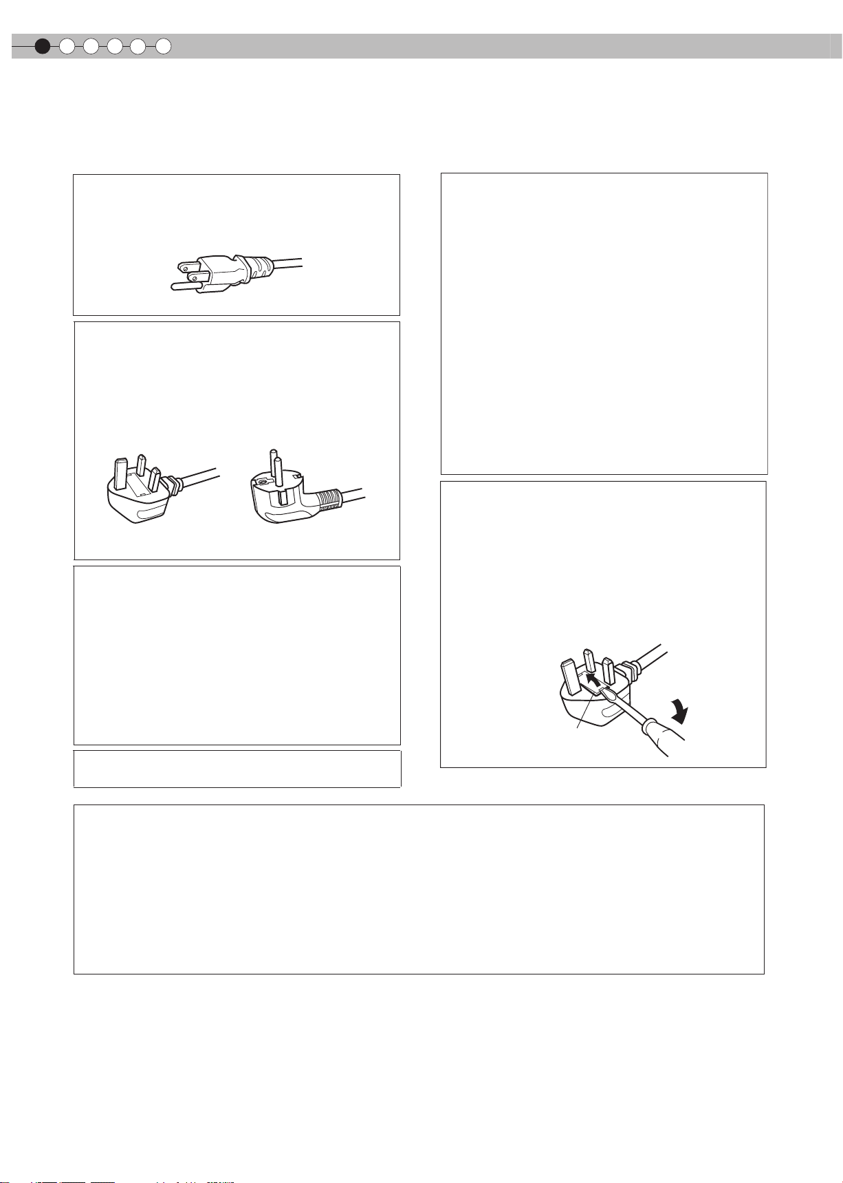
Use only the following power cord.
Power cord
The power supply voltage rating of this product is
AC110V – AC240V. Use only the power cord designated
by our dealer to ensure Safety and EMC.
Ensure that the power cable used for the projector is the
correct type for the AC outlet in your country. Consult
your product dealer.
Power cord
For United Kingdom For European continent
countries
IMPORTANT (Europe only):
The wires in the mains lead on this product are colored
in accordance with the following cord:
Green-and-yellow : Earth
Blue : Neutral
Brown : Live
As these colors may not correspond with the colored
making identifying the terminals in your plug, proceed
as follows:
The wire which is colored green-and-yellow must be
connected to the terminal which is marked M with the
letter E or the safety earth or colored green or greenand-yellow.
The wire which is colored blue must be connected to
the terminal which is marked with the letter N or colored
black.
The wire which is colored brown must be connected to
the terminal which is marked with the letter L or colored
red.
POWER CONNECTION
(United Kingdom only)
HOW TO REPLACE THE FUSE:
When replacing the fuse, be sure to use only a correctly
rated approved type, re-fit the fuse cover.
IF IN DOUBT —— CONSULT A COMPETENT ELECTRICIAN.
Open the fuse compartment with the blade screwdriver,
and replace the fuse.
(* An example is shown in the illustration below.)
Fuse
Dear Customer,
This apparatus is in conformance with the valid European directives and standards regarding electromagnetic
compatibility and electrical safety.
European representative of Victor Company of Japan, Limited is:
JVC Technical Services Europe GmbH
Postfach 10 05 04
61145 Friedberg
Germany
Getting started
4
Page 5
Information for Users on Disposal of Old Equipment and Batteries
[European Union only]
These symbols indicate that equipment with these symbols should not be disposed of
as general household waste. If you want to dispose of the product or battery, please
consider the collection systems or facilities for appropriate recycling.
Notice: The sign Pb below the symbol for batteries indicates that this battery
contains lead.
Battery
Products
Benutzerinformationen zur Entsorgung alter Geräte und Batterien
[Nur Europäische Union]
Diese Symbole zeigen an, dass derartig gekennzeichnete Geräte nicht als normaler
Haushaltsabfall entsorgt werden dürfen. Wenden Sie sich zur Entsorgung des Produkts
oder der Batterie an die hierfür vorgesehenen Sammelstellen oder Einrichtungen, damit
eine fachgerechte Wiederverwertung möglich ist.
ENGLISH
ENGLISH
DEUTSCH
Getting Started
Preparation
Basic Operation
Batterie
Hinweis: Das Zeichen Pb unterhalb des Batteriesymbols gibt an, dass diese Batterie
Blei enthält.
Produkte
FRANÇAIS
Informations relatives à l’élimination des appareils et des piles usagés, à l’intention des utilisateurs
[Union européenne seulement]
Si ces symboles figurent sur les produits, cela signifie qu’ils ne doivent pas être jetés
comme déchets ménagers. Si vous voulez jeter ce produit ou cette pile, veuillez
considérer le système de collection de déchets ou les centres de recyclage appropriés.
Notification: La marque Pb en dessous du symbole des piles indique que cette pile
contient du plomb.
Pile
Produits
NEDERLANDS
Informatie voor gebruikers over het verwijderen van oude apparatuur en batterijen
Settings
Troubleshooting
Producten
Batterij
[Alleen Europese Unie]
Deze symbolen gev en aan d at apparatuur met dit symbool n iet mag worden
weggegooid als algemeen huishoudelijk afval. Als u het product of de batterij wilt
weggooien, kunt u inzamelsystemen of faciliteiten voor een geschikte recycling
gebruiken.
Opmerking: Het teken Pb onder het batterijsymbool geeft aan dat deze batterij lood
bevat.
Others
5
Page 6
1
Getting started
Información para los usuarios sobre la eliminación de baterías/pilas usadas
[Sólo Unión Europea]
Estos símbolos indican que el equipo con estos símbolos no debe desecharse con la
basura doméstica. Si desea desechar el producto o batería/pila, acuda a los sistemas
o centros de recogida para que los reciclen debidamente.
ESPAÑOL / CASTELLANO
Atención: La indicación Pb debajo del símbolo de batería/pila indica que ésta contiene
plomo.
Baterías/pilas
Productos
Informazioni per gli utenti sullo smaltimento delle apparecchiature e batterie obsolete
[Solo per l’Unione Europea]
Questi simboli indicano che le apparecchiature a cui sono relativi non devono essere
smaltite tra i rifiuti domestici generici. Se si desidera smaltire questo prodotto o questa
batteria, prendere in considerazione i sistemi o le strutture di raccolta appropriati per il
riciclaggio corretto.
Batteria
Nota: Il simbolo Pb sotto il simbolo delle batterie indica che questa batteria contiene
piombo.
Prodotti
PORTUGUÊS
Informação para os utilizadores acerca da eliminação de equipamento usado e pilhas
[Apenas União Europeia]
Estes símbolos indicam que o equipamento com estes símbolos não deve ser eliminado
juntamente com o restante lixo doméstico. Se pretende eliminar o produto ou a pilha,
utilize os sistemas de recolha ou instalações para uma reciclagem apropriada.
ITALIANO
Aviso: O sinal Pb abaixo do símbolo para pilhas indica que esta pilha contém chumbo.
Pilha
Produtos
Πληροφορίες για την απόρριψη παλαιού εξοπλισμού και μπαταριών
[ Ευρωπαϊκή Ένωση μόνο ]
Αυτά τα σύμβολα υποδηλώνουν ότι ο εξοπλισμός που τα φέρει δεν θα πρέπει να
απορριφθεί ως κοινό οικιακό απόρριμμα . Εάν επιθυμείτε την απόρριψη αυτού του
προϊόντος ή αυτής της μπαταρίας , χρησιμοποιήστε το σύστημα περισυλλογής ή
εγκαταστάσεις για ανάλογη ανακύκλωση .
Μπαταρία
Προϊόντα
Σημείωση : Το σύμβολο Pb κάτω από το σύμβολο μπαταρίας υποδηλώνει ότι η
μπαταρία περιέχει μόλυβδο .
ΕΛΛΗΝΙΚΑ
6
Page 7
Brugerinformation om bortskaffelse af gammelt udstyr og batterier
[Kun EU]
Disse symboler angiver, at udstyr med disse symboler ikke må bortskaffes som
almindeligt husholdningsaffald. Hvis du ønsker at smide dette produkt eller batteri ud,
bedes du overveje at bruge indsamlingssystemet eller steder, hvor der kan ske korrekt
genbrug.
ENGLISH
Getting Started
DANSK
Batteri
Produkter
Bemærk: Tegnet Pb under symbolet for batterierne angiver, at dette batteri indeholder
bly.
Tietoja vanhojen laitteiden ja akkujen hävittämisestä
[Vain Euroopan unioni]
Nämä symbolit ilmaisevat, että symboleilla merkittyä laitetta ei tulisi hävittää tavallisen
kotitalousjätteen mukana. Jos haluat hävittää tuotteen tai sen akun, tee se hyödyntämällä
akkujen keräyspisteitä tai muita kierrätyspaikkoja.
Huomautus: Akkusymbolin alapuolella oleva Pb-merkintä tarkoittaa, että akku sisältää
Akku
Tuotteet
lyijyä.
Information för användare gällande bortskaffning av gammal utrustning och batterier
[Endast den Europeiska unionen]
Dessa symboler indikerar att utrustning med dessa symboler inte ska hanteras som
vanligt hushållsavfall. Om du vill bortskaffa produkten eller batteriet ska du använda
uppsamlingssystem eller inrättningar för lämplig återvinning.
SUOMI
SVENSKA
Preparation
Basic Operation
Settings
Observera! Märkningen Pb under symbolen för batterier indikerar att detta batteri
innehåller bly.
Batteri
Produkter
Opplysninger til brukere om kassering av gammelt utstyr og batterier
[Bare EU]
Disse symbolene viser at utstyr med dette symbolet, ikke skal kastes sammen med
vanlig husholdningsavfall. Hvis du vil kassere dette produktet eller batteriet, skal du
vurdere å bruke innsamlingssystemene eller andre muligheter for riktig gjenbruk.
Merk: Tegnet Pb under symbolet for batterier, viser at batteriet inneholder bly.
Batteri
Produkter
NORSK
Troubleshooting
Others
7
Page 8
1
Getting started
Сведения для пользователей по утилизации старого оборудования и батарей
[только для Европейского союза]
Данные символы указывают на то, что оборудование, на которое они нанесены,
не должны утилизироваться, как обычные бытовые отходы. При необходимости
утилизировать такое изделие или батарею обратитесь в специальный пункт
сбора для их надлежащей переработки.
РУССКИЙ
Батарея
Уведомление: Надпись Pb под символом батар ей указывает на то, что данная
батарея содержит свинец.
Изделия
Informace pro uživatele k likvid aci starého zařízení a baterií
[Pouze Evropská unie]
Tyto symboly označují, že produkty s těmito symboly se nesmí likvidovat jako běžný
odpad. Pokud chcete produkt nebo baterii zlikvidovat, využijte sběrný systém nebo
jiné zařízení, které za jistí řádnou recyklaci.
Upozornění: Zna čka Pb pod sy mbolem p ro bate rie z namená, že tato baterie
obsahuje olovo.
Baterie
Produkty
Informacje dla użytkowników dotyczące poz bywania się zużytego sprzętu i baterii
[Tylko kraje Unii Europejskiej]
Te symbo l e ozna c zają, że sp r zętu n i e nal e ży wy r zucać r azem z odpa d ami
gospodarczymi. Jeśli trzeba po zbyć się tego produktu lub ba terii, proszę skorzystać
z systemu odbioru lub urządzeń do zbiórki odpadów elektr oni czn ych , w ce lu
odpowiedniego ponowne go ich przetworzenia.
ČESKY
POLSKI
Bateria
Uwaga: Oznaczenie Pb, znajdujące się pod symbolem baterii wskazuje, że ta bateria
zawiera ołów.
Produkty
Felhasználói információ az elhasznált be rendezések és akkumulátorok elhelyezéséről
[Csak az Európai Unióban]
Ez a szimbólum azt jelzi, hogy a berendezés nem helyezhető az általános háztartási
hulladék közé. Ha meg szeretne szabadulni a terméktől vagy az akkumulátortól, akkor
legyen tekintettel az gyűjtő rendszerre vagy intézményekre a megfelelő hasznosítás
érdekében.
Akkumulátor
Termékek
Megjegyzés: Az alábbi Pb szimbólum - ha az akkumulátoron megtalálható - azt jelzi,
hogy az akkumulátor ólmot tartalmaz.
MAGYAR
8
Page 9
THX Cert
ifi
cation
THX Certication
ENGLISH
Getting Started
THX Certification
THX Ltd. was founded by filmmaker George Lucas to improve the cinema and home
entertainment experience through strict engineering standards and breakthrough technologies.
THX has leveraged more than 25 years of filmmaking, cinema design and post-production
expertise to partner with JVC to engineer a best-in-class home theater projector.
With a strict focus on image quality and signal processing performance, THX certification
promises that this JVC projector is capable of presenting a wide range of video content at
maximum resolutions with the correct color and luminance levels. In addition, THX has created
a battery of signal processing tests that challenge the projector’s scaling, motion conversion
and de-interlacing capabilities. This type of in-depth analysis predicts how the projector will
present a variety of high definition and standard definition content.
The JVC projector also features THX Movie Mode, a pre-calibrated video setting for watching
movies on DVD, Blu-ray HD or broadcast television. This playback feature is designed to
recreate the cinema experience at home by setting the display’s gamma, luminance, color
temperature and other settings to mirror those used by filmmakers in post-production. THX
Movie Mode also ensures projector brightness is optimal for large screen viewing.
Preparation
Basic Operation
For detail information about ISF, please refer web site
http://www.imagingscience.com/
Settings
Troubleshooting
Others
9
Page 10

1
Getting started
Contents
Getting started
Safety Precautions.............................................2
THX Certication.................................................9
isf information.....................................................9
Contents...........................................................10
How to Read this Manual/Accessories/
Optional Accessories .......................................11
About this Manual ................................................11
Check the Accessories ...................................... 11
Optional Accessories..........................................11
Controls and features.............................................12
How to Use the Remote control ......................15
Loading Batteries..................................................15
Effective Range of Remote Control Unit...........15
Preparation
Selecting Connecting Devices....................16
Connecting......................................................17
Connecting via Video Cable and S-Video
Cable................................................................17
Connecting via Component Video Cable........17
Connecting via HDMI Cable..............................18
Connecting via HDMI-DVI Conversion Cable...18
Connecting via SCART-RCA Cable....................19
Settings
The structure of the Settings menu ................ 28
Setting Menu .................................................. 30
Procedures for Menu Operation ......................30
Setting Menu ......................................................31
Customizing Projected Images ................... 42
Changing the Initial Setting of Picture Mode .42
Registering User-dened Picture Mode ............43
Registering User-dened Picture Mode from the
Menu ...................................................................43
Troubleshooting
Troubleshooting .............................................. 44
What to Do When these Messages
Are Displayed .................................................46
About Warning Indicators
Actions to Be Taken for Warning Mode ...........47
Replacing the Lamp ....................................... 48
Procedure for Lamp Replacement ................. 48
Resetting Lamp Time .........................................50
Cleaning and Replacing the Filter .................51
.............................
47
Connecting via RGB Video Cable......................19
Connecting via PC Cable...................................20
Connecting via Trigger Cable.............................20
Installing the Projector and Screen .................21
Set Angle ................................................................. 21
Shift ........................................................................21
Screen Size and Projection Distance .............22
Basic Operation
Projecting Image..............................................24
Convenient Features during Projection .......... 26
Setting the Screen Size ....................................... 26
Masking the Surrounding Area of an Image. ....26
10
Others
RS-232C Interface .......................................... 52
RS-232C Specications .......................................52
Command Format ..............................................52
RS-232C Communication Examples ................ 55
Copyright and Caution .................................56
About Trademarks and Copyright ....................56
Caution .................................................................56
Mounting this Unit ..............................................57
Specications ............................................. 58
Dimensions .......................................................... 60
Index .....................................................61
Page 11
ENGLISH
Optional Accessories
About this Manual
Check the Accessories
How to Read this Manual/ Accessories/Optional Accessories
INPUT
● Buttons on the remote control are described as [Button Name].
HDMI 1
VIDEO
HDMI 2
S-VIDEO
COMP.
PC
This manual mainly describes the operating method using the remote control.
Getting Started
Preparation
● Items on the menu are described as “Selection Item”.
LENS
TEST
ASPECT
HIDE
LIGHT
■
Conventions in this manual
CINEMA
2
STAGE
BACK
CINEMA
3
DYNAMIC
P11 Indicates relevant pages for reference.
MENU
PICTURE MODE
CINEMA
1
NATURAL
Buttons to be used are colored in a darker
shade.
Remote Control ..................................... 1 piece
AAA size Batteries (for operation conrm) ............... 2 pieces
Power Cord For the US market (2 m) ................... 1 piece
Describes the limitations of the functions or usage.
Indicates good-to-know information.
Describes operational precautions.
Basic Operation
Settings
Power Cord For the EU market (2 m) ................... 1 piece
Power Cord For the UK market (2 m) ................... 1 piece
● Instruction manual, warranty card and other printed material are also included.
Please check with your authorized dealer for details.
● Replacement Lamp: BHL5010-S (Lamp Unit)
● Replacement Filter (black in appearance): PB006560999 (Inner Filter)
Troubleshooting
Others
11
Page 12
1
Getting started
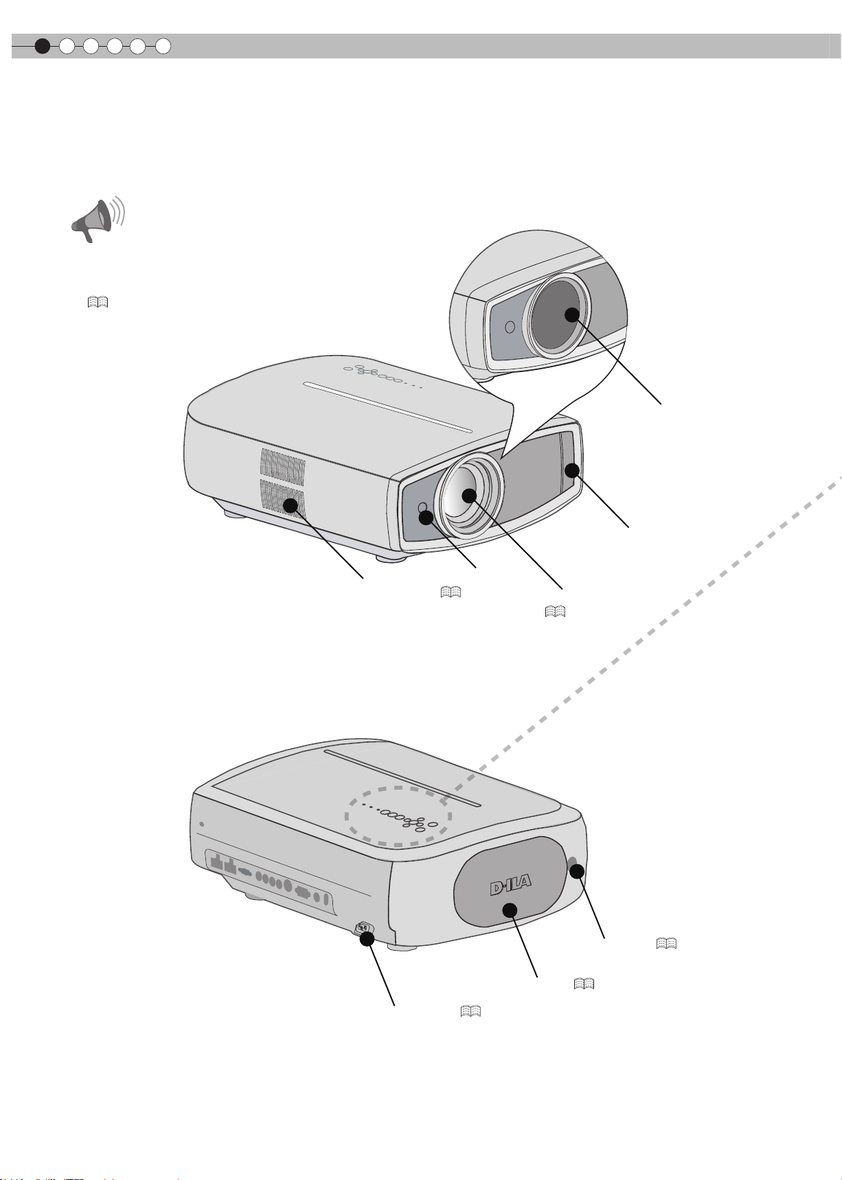
Controls and features
■
Front Side/Left Side
Do not place your fingers in the gap at the lens
●
during lens shift adjustment. This may cause injuries
if your ngers are caught in between the gap.
(
Do not let your ngers or other objects get caught in
●
between the lens cover while closing the cover. This
can cause injuries or malfunction.
■
Rear Side/Top Side/Right Side
CAUTION
)
P25
Exhaust Vent
Remote Sensor
P15
)
(
Lens Cover
Air Inlet
Lens Cover (opened)
(
P24
)
(closed)
12
To connect the power cord (
Lamp Cover (
)
P24
Remote Sensor (
)
P48
P15
)
Page 13
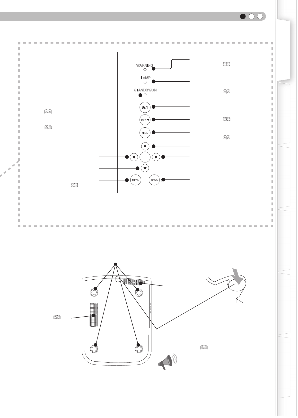
WARNING
ENGLISH
Light on (Red): Warning mode
P47
)
(
Getting Started
Light on (Red):
Standby mode
Light on (Green):
During projection
Blinking (Green):
Image is temporarily hidden
(
Blinking (Red):
Cool Down mode
(
P25
P25
)
)
Left button
Down button
To display the menu
(
P30
LAMP
STANDBY/ON
INPUT
HIDE
OK
MENU
)
BACK
Light on/Blinking (Orange):
Lamp warning
)
(
P47
To turn on/off the power
To switch input (
To hide the image temporarily
(
Up button
Right button
To return to the previous menu
P24
P25
)
)
Preparation
Basic Operation
■
Bottom Surface
Air inlets/Filter (
Feet: The height (0 to 5 mm) can be adjusted by turning the foot.
Air inlets
)
P51
Manual button for lens cover:
Press and hold the button to open the lens cover.
As this is used for maintenance, it is not necessary to
use it at normal times. (
CAUTION
P56
Settings
Troubleshooting
)
Others
Do not close lens cover when projecting. Otherwise
●
it will cause malfunction, heat and re.
13
Page 14
1
Getting started
Controls and features (continued)
■
Remote Control
To turn off the power
To select input mode (
To control lens (
To set the screen size (
To display test pattern
To display/close the menu
STAND BY
ON
To turn on the power
INPUT
P24
P24
P26
)
)
HDMI 1
VIDEO
LENS
S-VIDEO
ASPECT
)
TEST
HDMI 2
COMP.
PC
HIDE
LIGHT
To hide the image temporarily (
P25
)
To illuminate buttons on the remote control
for 7 seconds
To select or conrm
P30
)
(
MENU
PICTURE MODE
CINEMA
1
NATURAL
CINEMA
2
STAGE
BACK
CINEMA
3
DYNAMIC
To return to the previous menu
To switch picture mode (
P42
)
To set gamma (
To adjust color temperature (
P42
P42
USER2
USER1
GAMMA
)
C.TEMP
LENS.
AP.
THX
PIC.
ADJ.
To switche sequentially between Contrast,
Brightness, Color, Tint, Sharpness and
Detail enhance.
)
Lens Aperture (
P42
)
14
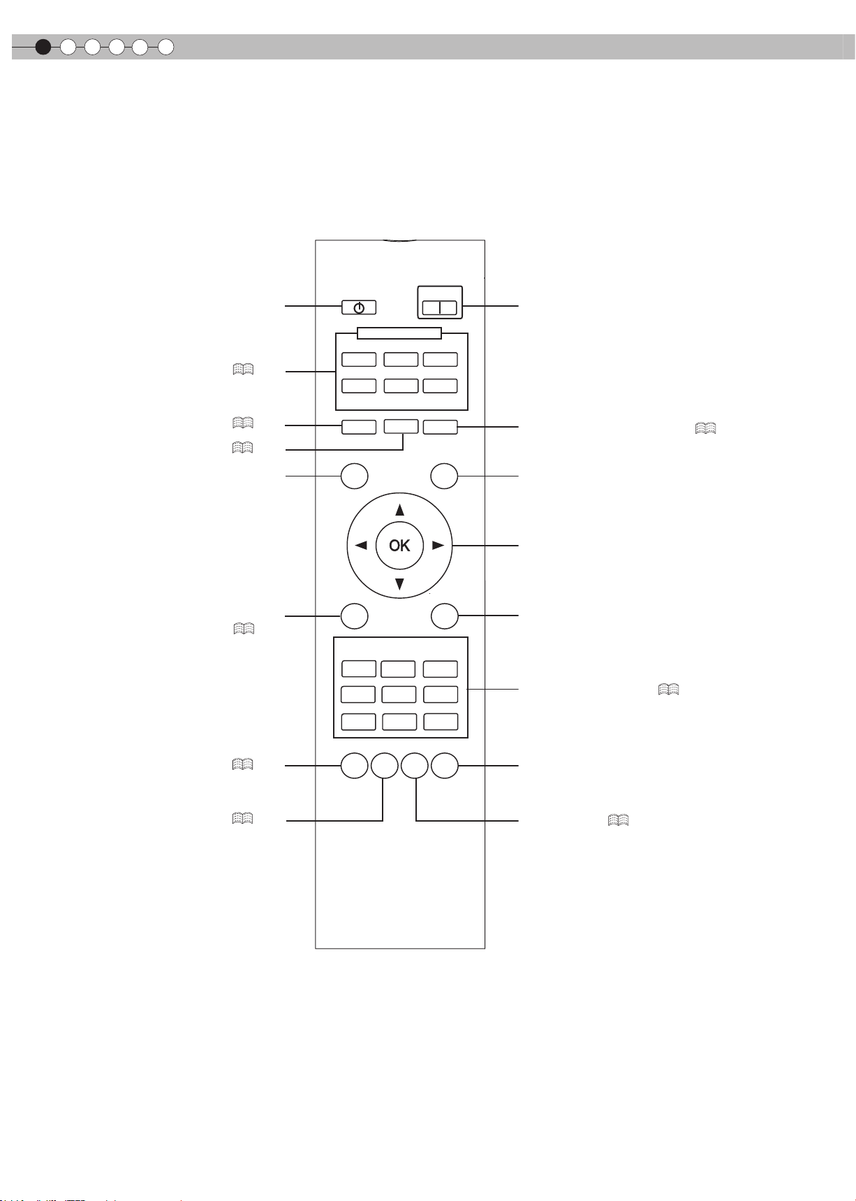
Page 15
ENGLISH
Effective Range of Remote Control Unit
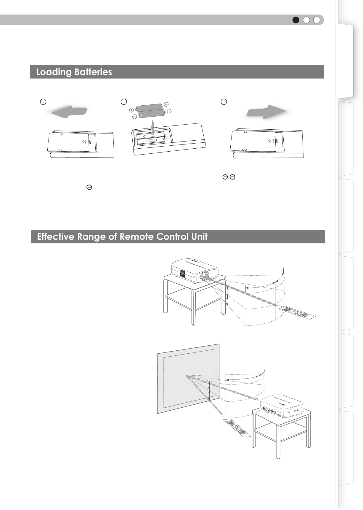
Loading Batteries
How to Use the Remote control
Getting Started
1
2 3
● If the remote control has to be brought closer to the projector to operate, it means that the batteries are wearing out.
When this happens, replace the batteries. Insert the batteries according to the
marks.
● Be sure to insert the end rst.
● If an error occurs when using the remote control, remove the batteries and wait for 5 minutes. Load the batteries again
and operate the remote control.
■ When directing the remote control
toward this unit
● When aiming the remote control towards the
remote sensor on this unit, ensure that the
distance to the sensor in front or at the rear of
this unit is within 7 m.
● If the remote control fails to work properly,
move closer to this unit.
This unit
30°
30°
20°
20°
Preparation
Basic Operation
Settings
■
When reecting off a screen
● Ensure that the total of distance A between
this unit and screen and distance B between
remote control and screen is within 7 m.
● As the efciency of signals reected from the
remote control unit differ with the type of
screen used, operable distance may decrease.
Screen
20°
A
20°
B
Remote control
30°
30°
Remote control
This unit
Troubleshooting
Others
15
Page 16
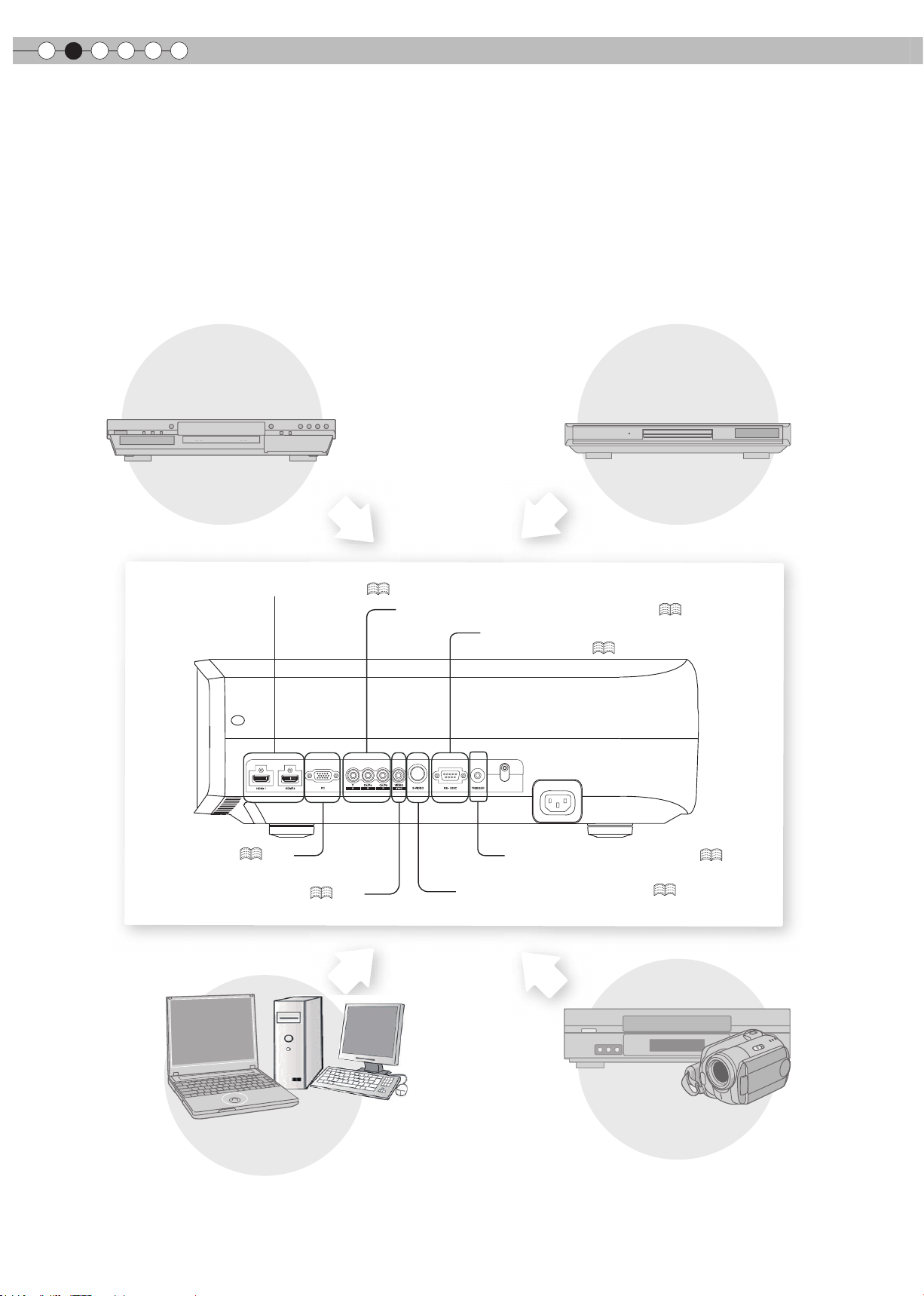
2
Preparation
Selecting Connecting Devices
● Do not turn on the power until connection is complete.
● The connection procedures differ according to the device used. For details, refer to the instruction manual of the device to be
connected.
● This device is used for image projection. Connect to an audio output device such as amplier and speaker for audio output
from the connected device.
● The images may not be displayed depending on the devices and cables to be connected.
For HDMI cable (sold separately), only use one that is HDMI-approved.
● It may not be possible to connect to this unit depending on the dimension of the connector cover of the cables to be
connected.
BD/DVD Recorder
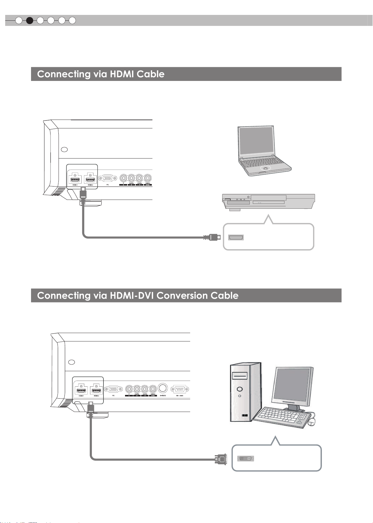
To connect via HDMI terminal (
BD/DVD Player
)
P18
To connect via component video terminals (
To connect RS-232C terminal
(external control) (
P52
)
P17
)
To connect via PC terminal (
To connect via video terminal (
16
P20
PC
)
P17
)
To connect via S-video terminal (
To connect via Trigger terminal (
P17
VCR and camcorder
)
P20
)
Page 17
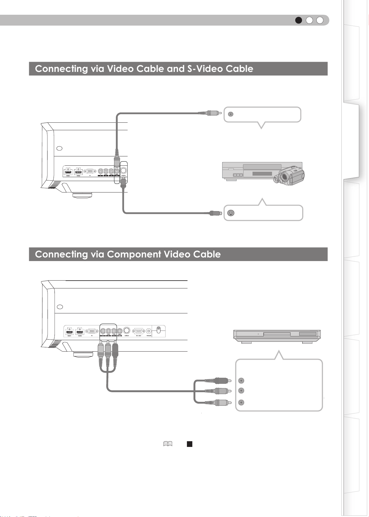
Connecting
Connecting via Component Video Cable
Connecting via Video Cable and S-Video Cable
ENGLISH
Getting Started
This unit
This unit
video cable
(sold separately)
To video input termina
SYNC
To S-video input terminal
S-video cable
(sold separately)
Video output
l
VCR and camcorder
Preparation
Basic Operation
S-video output
Settings
SYNC
●
Set “COMP.” in the setting menu to “Y Pb/Cb Pr/Cr”. ( P36 - 12 )
To component video input terminals
Component video cable
(sold separately)
BD/DVD player
Component video output
terminals
(red)
C
R/PR
C
(blue)
B/PB
Y (green)
Troubleshooting
Others
17
Page 18
2
Connecting via HDMI Cable
Connecting via HDMI-DVI Conversion Cable
Connecting(Continued)
Preparation
This unit
To HDMI 1 or HDMI 2 input terminal
HDMI cable (sold separately)
● If noise is produced, take PCs (Notebook PC) away from this unit.
● Use only HDMI-approved equipment.
● Reducing the length of the cable is recommended if there is no picture.
Notebook PC
BD/DVD recorder
HDMI output terminal
This unit
To HDMI 1 or HDMI 2 input terminal
HDMI-DVI conversion cable
(sold separately)
● If noise is produced, take PCs (desktop computer) away from this unit.
● Reducing the length of the cable is recommended if there is no picture.
Desktop computer
DVI output terminal
18
Page 19
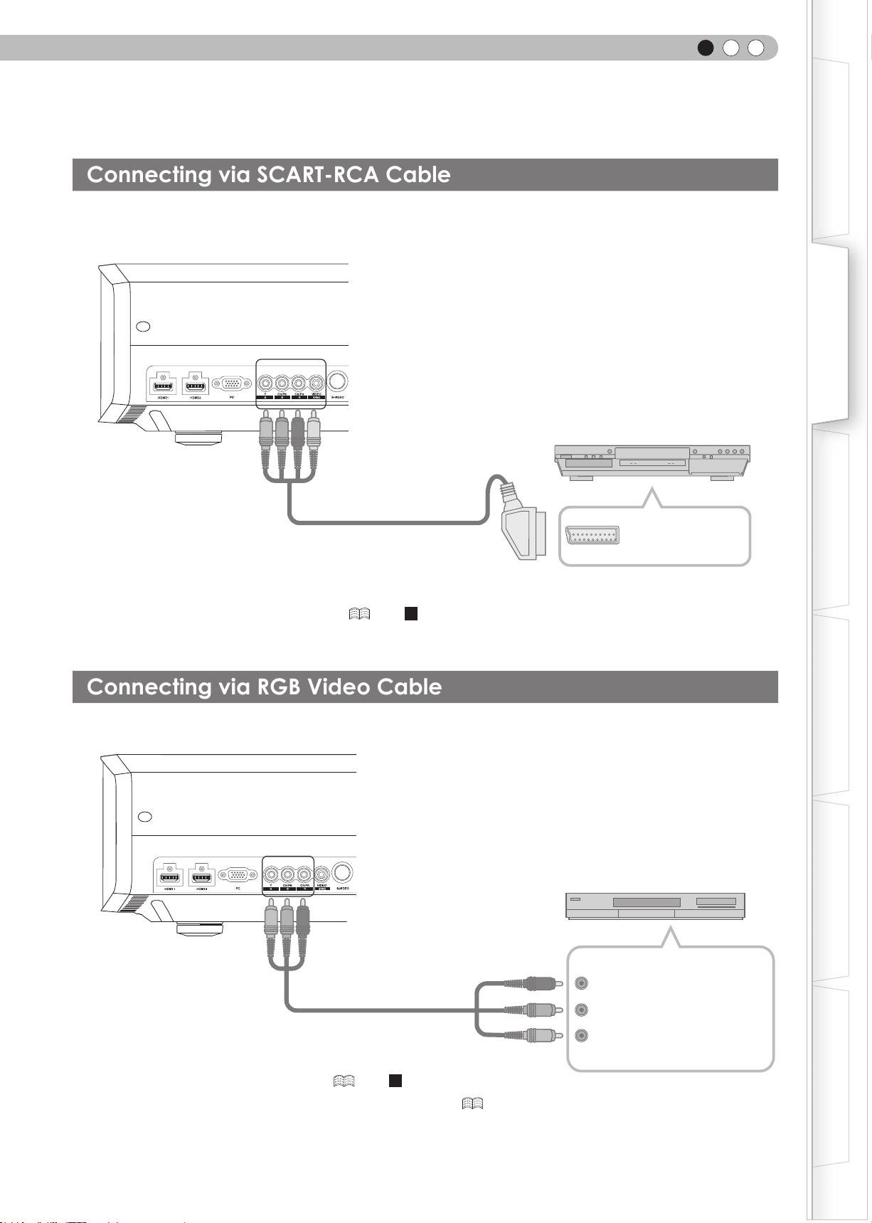
Connecting via SCART-RCA Cable
Connecting via RGB Video Cable
This unit
To RGB video and
sync signal input terminals
ENGLISH
Getting Started
Preparation
RS-232C
BD/DVD player for European market
Basic Operation
SCART-RCA cable
(sold separately)
● Set “COMP.” in the setting menu to “SCART”.( P36 -
This unit
RS-232C
12
SCART terminal
)
Settings
Troubleshooting
Device equipped with RGB output
To RGB video input terminals
RGB video cable
(sold separately)
● Set “COMP.” in the setting menu to “RGB”.( P36 -
● For information on compatible input signals, see “Specications”. ( P58)
12
RGB video output terminals
R(Red)
B(Blue)
G(Green)
(Includes sync signals)
)
Others
19
Page 20
2
Connecting via Trigger Cable
Connecting via PC Cable
Preparation
Connecting(Continued)
This unit
To PC input terminal
Notebook PC
PC cable(sold separately
)
● For information on supported input signals, please refer to “Specications” . ( P58)
This unit
SYNC
To Trigger output terminal
VGA output terminal
Screen
Do not supply the power to the other devices.
●
Do not connect audio terminals of the other devices such as
●
headphones etc. Otherwise, this may cause a malfunction of
the other devices or injury.
Using beyond the rated value will cause malfunction.
●
Exercise adequate caution to prevent short circuit as the trigger
●
terminal outputs a voltage of 12V.
CAUTION
20
Trigger cable
(sold separately)
Trigger input terminal
(Φ3.5)
Page 21
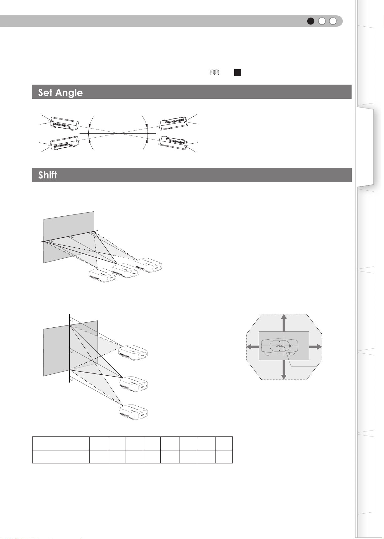
ENGLISH
Set Angle
Shift
Installing the Projector and Screen
While installing, please place this unit and the screen perpendicular to each other. Failing to do so may
increase trapezoidal distortion. Please refer to “Keystone”. ( P39 -
● The angle range which can be set for this unit is ±10°.
25
)
Getting Started
10°
10°
● Malfunctions may occur if the angle is not set within the above-mentioned range.
■
Left/Right position
* 0% up/down position (center)
Approximately 34% (maximum) of
the projected image
■
Up/Down position
* 0% left/right position (center)
10°
10°
Approximately 34% (maximum) of
the projected image
■
Shifting range of projected image
Preparation
Basic Operation
Settings
Approximately 80% (maximum) of
the projected image
Approximately 80% (maximum) of
Lens shift correlation chart:
Left-Right Shift(%) 0% 5% 10% 15% 20% 25% 30% 34%
Up-Down Shift(%) 80% 74% 66% 57% 47% 34% 18% 0%
● Maximum Up-Down shift varies with the amount of Left-Right shift. Likewise,
maximum Left-Right shift varies with the amount of Up-Down shift.
the projected image
● The values on the chart are intended to act as a guide. Use them for reference
during installation.
80%
80%
34%34%
Lens center
Troubleshooting
Others
21
Page 22
2
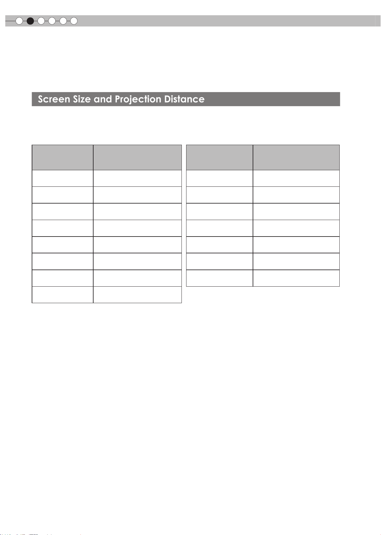
Screen Size and Projection Distance
Preparation
Installing the Projector and
Screen(Continued)
Determine the distance from the lens to the screen to achieve your desired screen size.
This unit uses a 2.0x power zoom lens for projection.
■
Relationship Between Projection Screen Size and Projection Distance
Projection Screen Size
(Diagonal Length)
Aspect Ratio 16:9
60"
(Approx. 1.52m)
70"
(Approx. 1.78m)
80"
(Approx. 2.03m)
90"
(Approx. 2.29m)
100"
(Approx. 2.54m)
110"
(Approx. 2.79m)
120"
(Approx. 3.05m)
130"
(Approx. 3.30m)
Approximate Projection Distance
W(Wide) to T(Tele)
Approx. 1.78m to
Approx. 2.09m to Approx. 4.28m
Approx. 2.40m to
Approx. 2.70m to
Approx. 3.01m to
Approx. 3.31m to
Approx. 3.62m to Approx. 7.36m
Approx. 3.92m to
Approx. 3.66m
Approx. 4.89m
Approx. 5.51m
Approx. 6.13m
Approx. 6.75m
Approx. 7.98m
Projection Screen Size
(Diagonal Length)
Aspect Ratio 16:9
140"
(Approx. 3.56m)
150"
(Approx. 3.81m)
160"
(Approx. 4.06m)
170"
(Approx. 4.32m)
180"
(Approx. 4.57m)
190"
(Approx. 4.83m)
200"
(Approx. 5.08m)
Approximate Projection Distance
W(Wide) to T(Tele)
Approx. 4.23m to Approx. 8.60m
Approx. 4.53m to
Approx. 4.84m to Approx. 9.84m
Approx. 5.14m to Approx. 10.45m
Approx. 5.45m to Approx. 11.07m
Approx. 5.75m to Approx. 11.68m
Approx. 6.06m to
Approx. 9.22m
Approx. 12.30m
● The projection distances in the table are provided only as a guide. Use them as a reference during installation.
● To adjust the installation, use a projected image of aspect ratio 16:9.
22
Page 23

MEMO
ENGLISH
Getting Started
Preparation
Basic Operation
Settings
Troubleshooting
Others
23
Page 24
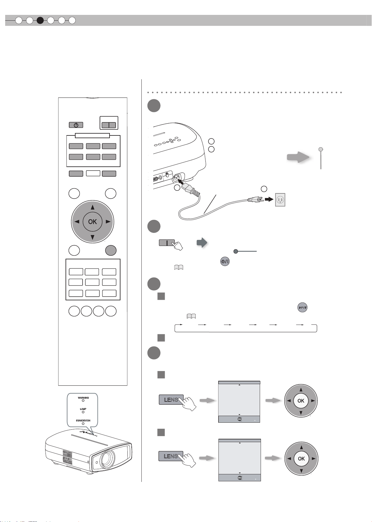
3
BACK
Back
Operate
Select
Exit
MENU
Zoom
Lens Control
Basic Operation
Projecting Image
This section describes the basic operations to project input images on the screen.
Preparation
1
Insert the power plug to the power
STAND BY
HDMI 1
VIDEO
LENS
INPUT
HDMI 2
S-VIDEO
ASPECT
ON
COMP.
PC
HIDE
outlet
Connect to this unit
1
2
Connect to the power outlet
STANDBY/ON
Light on (Red)
TEST
MENU
PICTURE MODE
CINEMA
1
NATURAL
USER1
C.TEMP
GAMMA
CINEMA
2
STAGE
USER2
LENS.
AP.
LIGHT
BACK
CINEMA
3
DYNAMIC
THX
PIC.
ADJ.
1
2
Turn on the power
ON
Power Cord
(Supplied)
2
STANDBY/ON
Light on (Green)
● You can also press the button on the unit to turn on the power.
(
3
Project the image
1
Select input mode
2
Play back the selected device
4
Adjusts image focus, size (zoom), and
P13)
● The lens cover will be opened.
● You can also select the input mode by pressing the
unit. (
P13)
HDMI 1 HDMI 2 COMP. Video S-Video PC
INPUT
button on the
position (shift).
24
1
WARNING
LAMP
ST ANDBY/ON
Adjust the focus
LENS
Lens Control
Focus
Exit
MENU
Select
Operate
Back
BACK
Adjust accordingly by pressing
the up/down buttons
Adjust the image size (zoom)
2
LENS
Adjust accordingly by
pressing the up/down
buttons
Page 25
Adjust image position (shift).
3
Lens control
LENS
Shift
ENGLISH
Getting Started
TIPS
Select
Back
BACK
Operate
● After adjusting the image position, it may be necessary to select
“Pixel Adjust” from the Settings menu “Installation”.
(
● Every time the
will be switched among “Focus”, “Zoom” and “Shift”.
5
LENS
4
To end
BACK
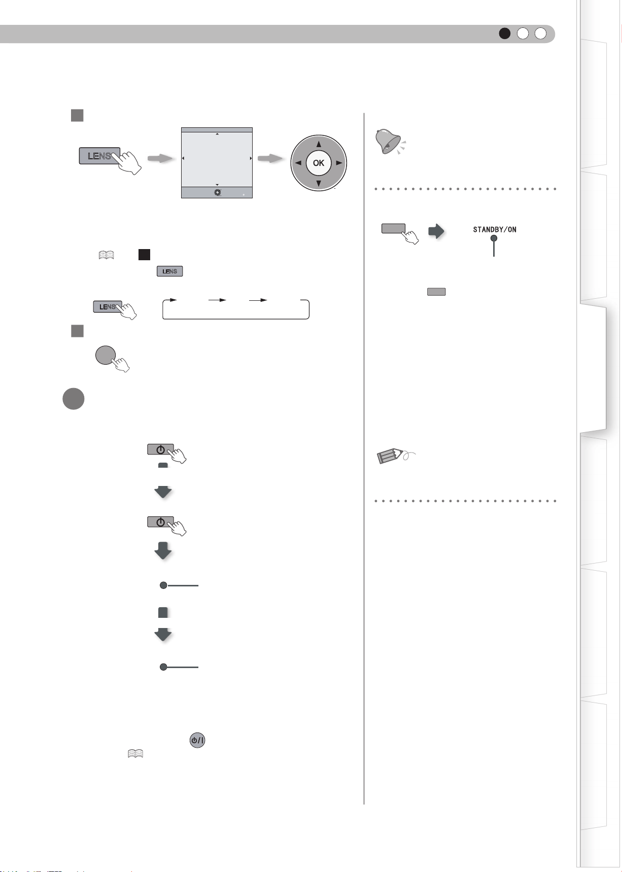
Turn off the power
23
P38 -
)
LENS
Focus Zoom
STAND BY
While a confirmation
screen is displayed
STAND BY
STAND BY/ON
Cool Down mode
STAND BY/ON
button is pressed, the adjustment item
Blinking (Red Lamp)
Light on (Red Lamp)
Adjust accordingly by
pressing the up/down
buttons
Shift
● When power off, the lens cover will be closed.
● The power cannot be turned off within approximately 90 seconds
after it has been turned on. Start operation only after 90 seconds
time.
● You can also press the button on the unit to turn off the
power. (
P13)
● Pull out the power plug when the unit will not be used for a
prolonged time.
You can hide the image temporarily
You can hide the image temporarily.
HIDE
Green light blinks
when the image is
hidden.
● Press the
image.
HIDE
button again to display
● The power cannot be turned off when the
image is temporarily hidden.
MEMO
About Cool Down mode
● The Cool Down mode is a function to
cool down the lamp for approximately 60
seconds after projection is complete. This
function prevents the internal parts of the
unit from deformation or damage due to
overheating of the lamp. It also prevents
lamp blowout and premature shortening
of lamp life.
During Cool Down mode, the [STANDBY/
●
ON] indicator blinks in red.
● After the Cool Down mode is complete,
the unit automatically returns to standby
mode.
● Do not pull out the power plug during
Cool Down mode. This may shorten the
lamp life and cause a malfunction.
Preparation
Basic Operation
Settings
Troubleshooting
Others
25
Page 26
3
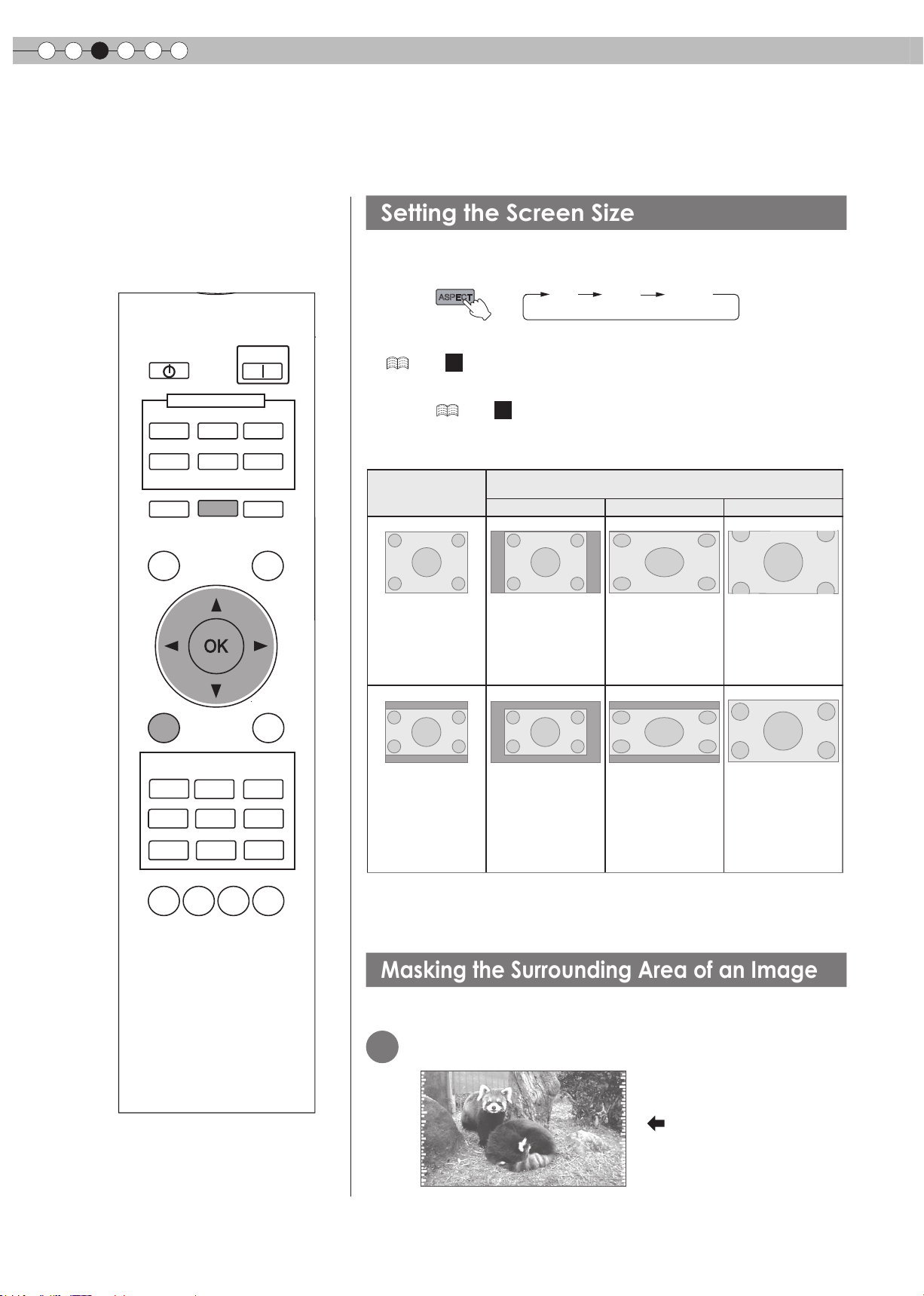
Setting the Screen Size
Masking the Surrounding Area of an Image
Basic Operation
Convenient Features during Projection
You can change the screen size of the projected image or hide the surrounding area of an image for which
quality at the outer area has deteriorated.
The projected image can be set to a most appropriate screen size
(aspect ratio).
ASPECT
4:3 16:9 zoom
STAND BY
HDMI 1
VIDEO
LENS
TEST
MENU
PICTURE MODE
CINEMA
1
NATURAL
USER1
INPUT
HDMI 2
S-VIDEO
ASPECT
CINEMA
2
STAGE
USER2
ON
COMP.
PC
HIDE
LIGHT
BACK
CINEMA
3
DYNAMIC
THX
● The screen size can also be set from “Aspect(Video)” of the setting menu.
(
P37 -
16
)
● When PC signals are input, the “Aspect(Computer)” setting will be available
instead. (
■
Input Image and Projected Image by Different Screen Size
P37 -
Settings
Input Image
SDTV (4:3)
SDTV(4:3)
Image recorded in
landscape (black
bands on top and
bottom) of DVD
software
)
17
4:3
Aspect Ratio:
Same
Most
appropriate
screen size
Aspect Ratio:
Same
Small image is
projected
Screen Size
16:9
Aspect Ratio:
Landscape
Image is stretched
horizontally
Aspect Ratio:
Landscape
Image is
stretched
horizontally
Zoom
Aspect Ratio:
Same
Top and bottom of
the image are
missing
Aspect Ratio:
Same
Most appropriate
screen size
LENS.
● Depending on the input image, selecting “4:3” may result in a vertically
GAMMA
C.TEMP
26
AP.
PIC.
ADJ.
stretched image, while selecting “16:9” provides you with the most
appropriate screen size.
Images for which quality at the outer area has deteriorated can be projected by
masking (hiding) the surrounding area of the projected image.
1
Project the image
Image for which quality
at the outer area has
deteriorated.
Page 27
Mask the image
Video/S-Video
COMP.
Picture Position
Exit
MENU
BACK
Back
Select
Operate
HDMI
Film Mode
Auto
Over scan
Off
Aspect(Video)
Aspect(Computer)
V-stretch
16:9
Auto
Off
Mask
Off
5%
Off
2.5%
Input Signal
PC
2
1
Display the setting menu
MENU
Picture Adjust
Picture Mode
Contrast
Brightness
Color
Tint
Color Temp.
Gamma
Advanced
Lens Aperture
Exit
MENU
Select
ENGLISH
Getting Started
MEMO
● Masking is available only when high
Natural
0
0
0
0
6500K
Normal
0
Reset
Operate
Back
BACK
denition images are input.
Preparation
2
Select “Input Signal”
Select
1
3
Set a mask value
1
Select
“Mask”
2
Confirm
Confirm
2
Input Signal
HDMI
COMP.
Video/S-Video
PC
Picture Position
Aspect(Video)
Aspect(Computer)
V-stretch
Over scan
Mask
Film Mode
Exit
MENU
Select
自动
Operate
Basic Operation
Settings
16:9
Auto
Off
Off
2.5%
5%
5%
Off
Auto
Back
BACK
3
Example:
When the “Mask” value is
changed from “Off”
To end
MENU
Troubleshooting
“5%”
Others
27
Page 28
4
Settings
The structure of the Settings menu
The menu for this device is structured as follows:
There are items that cannot be modied
●
without entry.
CAUTION
Picture Adjust
01
Picture Mode
02
Contrast
03
Brightness
04
Color
05
Tint
06
Color Temp.
07
Gamma
08
Advanced
09
Lens Aperture
10
Reset
Adjusts the pattern of the projected image.
Setting: Cinema 1, Cinema 2, Cinema 3, Natural, Stage, Dynamic, User 1, User 2, THX
Adjusts the contrast of the projected image.
Setting: –50 to 50
Adjusts the brightness of the projected image.
Setting: –50 to 50
Adjusts the color density of the projected image.
Setting: –50 to 50
Adjusts the hue of the projected image.
Setting: –50 to 50
Sets the color temperature of the projected image.
Setting: 5800K, 6500K, 7500K, 9300K, High Bright, Custom 1, Custom 2, Custom 3
Sets the gradation characteristics of the projected image.
Setting: Normal, A, B, C, D, Custom 1, Custom 2, Custom 3
Adjusts the contours of the image and detailed composition of the image.
Setting: Sharpness, NR, CTI, Color Management, Clear Motion Drive
Sets the lens aperture.
Setting: –15 to 0
Reset the setting.
Input Signal
11
HDMI
12
COMP.
13
Video/S-Video
14
PC
15
Picture Position
16
Aspect (Video)
17
Aspect (Computer)
18
V-Stretch
19
Over Scan
20
Mask
21
Film Mode
Congures HDMI input signal.
Setting: Input, Color Space, Control with HDMI
Congures the input signal for the component video input terminals.
Setting: Y Pb/Cb Pr/Cr, RGB, SCART
Congures the Video/S-Video input signals.
Setting: NTSC, Setup Level, Color System
Congures PC input.
Setting: Auto Alignment, Tracking, Phase, Picture Position
Adjusts the horizontal/vertical position of the projected image.
Congures the screen size of the projected image.
Setting: 4:3, 16:9, Zoom
Congures the screen size of the projected image.
Setting: Auto, 1:1, Full
When set to “On”, the projected 2.35:1 image will be stretched vertically to the panel resolution.
Setting: On, Off
Selects whether or not to set over scan for the SD video signal.
Setting: On, Off
Masks (Hides) the outer area of the projected image.
Setting: 2.5, 5, Off
Selects this to view movies shot on lm.
Setting: Auto, lm, Off
28
Page 29
Installation
22
Lens Control
23
Pixel Adjust
24
Installation Style
25
Keystone
26
Screen Adjust
ENGLISH
Controls the individual motorized function of the lens when setting up the projector.
Setting: Focus, Zoom, shift, Image pattern, Lock
Makes ne adjustments of 1 pixel unit for each minor color shift in the horizontal/vertical direction
of the image.
Setting: horizontal and vertical
Flips the image to the left or right, up or down according to the projection state of the projector.
Setting: Front, Ceiling Mount (F), Rear Ceiling Mount (R)
Compensates for trapezoidal distortion caused by installation.
Corrects skewed white balance derived from the reective characteristics of the screen.
Setting: Off, A, B, C
Getting Started
Preparation
Display Setup
27
Back Color
28
Menu Position
29
Menu Display
30
Line Display
31
Source Display
32
Logo
33
Language
Function
34
Lamp Power
35
Trigger
36
Test Pattern
37
Off Timer
38
High Altitude
Mode
Congures the screen color displayed when there is no input signal.
Setting: Blue, Black
Sets the display position of the menu. The possible positions for displaying the menu are at the
four corners or at center of the screen.
Sets the duration for displaying the menu.
Setting: 15sec, On
Sets whether to display the input setting when switching the input.
Setting: 5 sec, Off
Sets whether to display the source of input signals when changing the input.
Setting: On, Off
Sets whether to display “Logo” during startup.
Setting: On, Off
Sets the language of the menu display (12 languages).
Congures the output of the light-source lamp.
Setting: Normal, High
Congures the output of Trigger terminal.
Setting: Off, On(Power), On(V-Stretch)
Display 6 types of test patterns.
Automatically powers off when there is no operation for a certain duration.
Setting: 1 hour, 2 hours, 3 hours, 4 hours
Selects this when using the projector in a location of low atmospheric pressure (higher than 900
meters above sea level).
Setting: On, Off
Basic Operation
Settings
Troubleshooting
Information
Input Image Connector, Input Source Name, PC resolution, PC H Frequency, PC V Frequency, Deep Color Depth, and
Lamp Use are displayed.
Others
29
Page 30
4
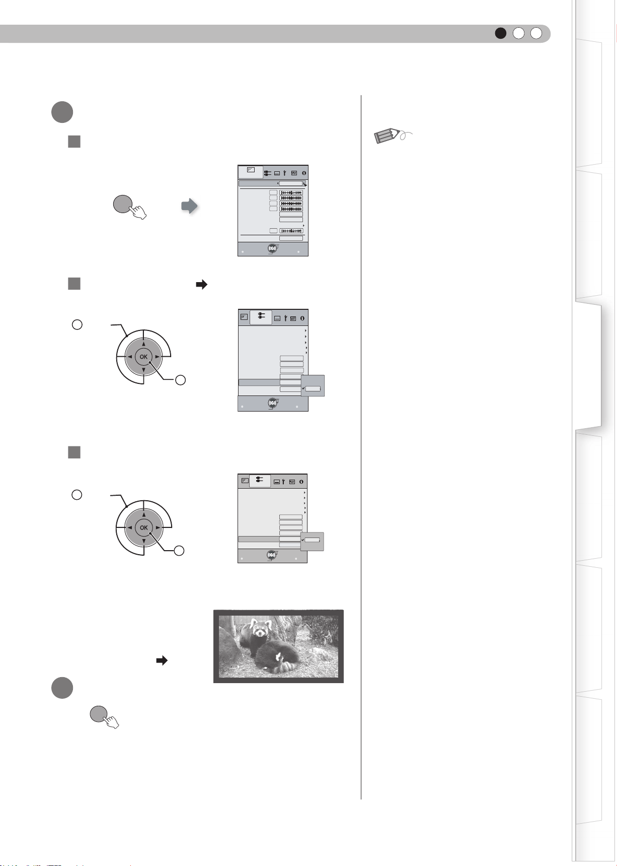
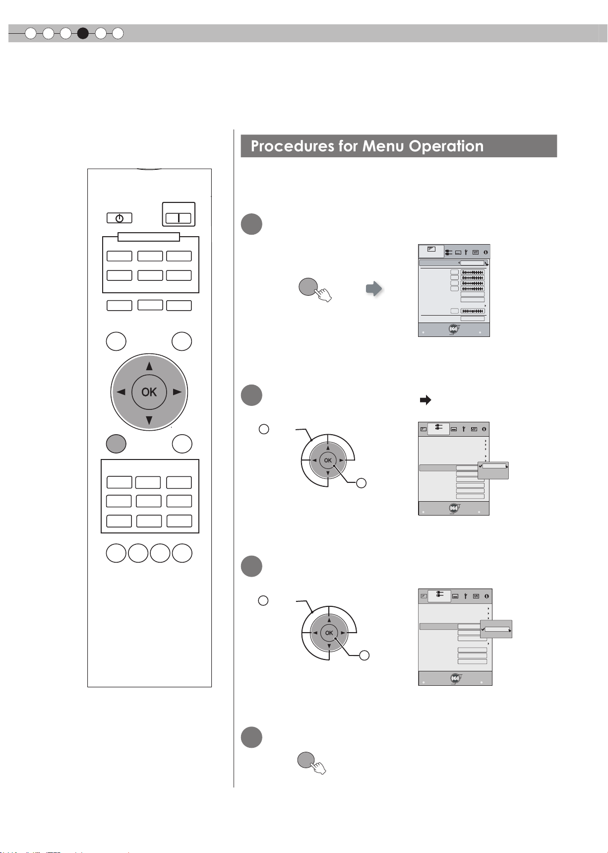
Procedures for Menu Operation
Settings
Setting Menu
Projected images can be adjusted to a desired view by changing the initial settings.
Example:
When changing “Aspect(Video)” from “4:3” to “16:9”
STAND BY
HDMI 1
VIDEO
LENS
TEST
MENU
CINEMA
1
NATURAL
USER1
INPUT
HDMI 2
S-VIDEO
ASPECT
PICTURE MODE
CINEMA
2
DYNAMIC
STAGE
USER2
ON
COMP.
PC
HIDE
LIGHT
BACK
CINEMA
3
THX
1
Display the setting menu
Picture Adjust
Picture Mode
Contrast
Brightness
MENU
2
Select “Input Signal” “Aspect(Video)”
Select
1
Confirm
2
Color
Tint
Color Temp.
Gamma
Advanced
Lens Aperture
Exit
MENU
Input Signal
HDMI
COMP.
Video/S-Video
PC
Picture Position
Aspect(
Video
Aspect(Computer)
V-stretch
Over scan
Mask
Film Mode
Exit
MENU
Select
Select
Natural
0
0
0
0
6500K
Normal
0
Reset
Operate
Back
BACK
Zoom
Auto
Auto
Operate
4:3
4:3
16:9
Off
Off
5%
Back
BACK
)
LENS.
GAMMA
C.TEMP
AP.
PIC.
ADJ.
30
3
Set to “16:9”
1
Select
4
To end
MENU
Confirm
2
Input Signal
HDMI
COMP.
Video/S-Video
Video
)
Aspect(
Aspect(Computer)
V-stretch
Picture Position
Over scan
Mask
Film Mode
Exit
MENU
Select
16:9
Auto
Auto
Operate
4:3
16:9
Zoom
Off
Off
5%
Back
BACK
Page 31

Setting Menu
Item values shown in are factory settings.
● Items that can be congured differ according to the input signals.
ENGLISH
Getting Started
There are items that cannot be modied
●
without entry.
CAUTION
Picture Adjust
01
Picture Mode
Selects Picture Mode(Cinema 1, Cinema 2, Cinema 3, Natural, Stage, Dynamic, User 1, User 2 and THX).
Cinema 1 This is the picture setting closest to lm. It is best suited for general movie viewing.
Cinema 2
Cinema 3 This is the picture setting best suited for viewing animated movies.
Natural This is the picture setting for natural hues and tones. It is best suited for viewing dramas and video.
Stage This is the picture setting best suited for watching live concerts and stage performances.
Dynamic
THX This is the picture setting certied by THX Ltd.
02
Contrast
Adjusts the contrast of the projected image.
(Black) –50 to 50 (White)
03
Brightness
Adjusts the brightness of the projected image.
(Darken) –50 to 50 (Brighten)
04
Color
Adjusts the color density of the projected image.
(Lighten) –50 to 50 (Darken)
05
Tint
Adjusts the hue of the projected image.
(Red) –50 to 50 (Green)
This is the picture setting for vivid hues based on HDTV standards. It is best suited for viewing action
movies and movies with vivid colors.
This is the picture setting best suited for viewing the picture in a room that cannot be made completely
dark.
Preparation
Basic Operation
Settings
Troubleshooting
Others
31
Page 32
4
Settings
Setting Menu (Continued)
Picture Adjust > Color Temp.
06
Color Temp.
Sets the color temperature of the projected image. (Cannot set when the “Picture Mode” in “THX”.)
5800K
6500K Select this to have a balanced image.
7500K
9300K
High Bright Select this to get the brightest image.
Custom 1
Custom 2
Custom 3
Select this to give a reddish tinge to the
image.
Select this to give a bluish tinge to the
image.
Select this to give a greater bluish tinge
than 7500K.
Correction
Value
Gain
(Bright part)
Offset
(Dark part)
Correction
Value
Gain
(Bright part)
Offset
(Dark part)
Correction
Value
Gain
(Bright part)
Offset
(Dark part)
Based on this selection of Correction Value (5800K, 6500K, 7500K,
9300K, H.B.), adjusts the following Gains and Offsets.
Red (Less red) –50 to 50 (More red)
Green (Less green) –50 to 50 (More green)
Blue (Less blue) –50 to 50 (More blue)
Red (Less red) –50 to 50 (More red)
Green (Less green) –50 to 50 (More green)
Blue (Less blue) –50 to 50 (More blue)
Only offset can be set.
● The red, green and blue colors can be adjusted and registered respectively.
● This setting can also be congured from the remote control. ( P14)
32
Page 33

ENGLISH
Picture Adjust > Gamma
07
Gamma
Sets the gradation characteristics of the projected image. (Cannot set when the “Picture Mode” in “THX”.)
Normal
A Set gamma to “A”.
B Set gamma to “B”.
C Set gamma to “C”.
D Set gamma to “D”. This setting provides brighter midtones.
Custom 1
Custom 2
Custom 3
(Gamma Setup)
For normal circumstances, select this
setting.
This is the setting for Standard Tones.
This is the setting for expressing rich dark
tones.
This is the setting for the characteristic
tonal qualities of lm.
This setting provides even richer darker
tones than setting B.
Three different kinds of gamma can be set according to your preferences.
Correction
Value
The coefcient (1.8 to 2.6) of the gamma curve can be selected.
The gamma curve for the colors (Red, Green, Blue) can be adjusted
Gamma
Adjustment*
separately.
Adjusting “White” will adjust for all “Red, Green, Blue” values. The
gamma curve displays the value for “Green”.
Copy Copy the adjusted gamma data.
Paste Paste the copied gamma data.
Reset
Return the gamma coefficients to the values 2.2 set by “Correction
Value”.
Getting Started
Preparation
Basic Operation
● “Normal” is suitable for normal circumstances but other settings can be selected according to your preferences.
● This setting can also be congured from the remote control. ( P14)
* “Gamma Adjustment”
1
Select the reference gamma curve coefcient (1.8 ~ 2.6) in “Correction Value”.
2
Select the color to be adjusted in the gamma adjustment screen.
Picture Adjust
Gamma
Normal
Correction Value
A
White
Red
B
Geen
C
Blue
D
Costom1
Copy
Costom2
Paste
Costom3
Reset
Operate
Exit
MENU
Select
Adjust the gamma curve in the gamma curve adjustment screen.
3
Picture Adjust
Gamma
Normal
Correction Value
A
White
Red
B
Geen
C
Blue
D
Costom1
Copy
Costom2
Paste
Costom3
Reset
Input: 10%
Output:100
Back
Exit
MENU
Select
Operate
Select the point where the gradation (brightness)
is to be adjusted with the
2.2
1023
512
0
50
100(%)
Check
Back
Before
TEST
BACK
Picture Adjust
2.2
1023
512
0
50
100(%)
Check
Back
Before
TEST
BACK
Gamma
Normal
A
B
C
D
Costom1
Costom2
Costom3
Exit
MENU
Correction Value
Select
White
Red
Geen
Blue
Copy
Paste
Reset
Input: 50%
Output: 580
Back
Operate
2.2
1023
512
0
50
100(%)
Check
Back
After
TEST
BACK
Adjust the gradation (brightness) with
the
/ buttons.
/ buttons.
Settings
Troubleshooting
● You can switch between “Before” and “After” using the [TEST] button of the remote control.
To end
4
BACKBACK
Save gamma data?
Yes
No
OK
● If gamma curve is adjusted repeatedly, calculation errors will be accumulated and the gamma curve may not be able to
revert back to its original form. In that case, select “Reset”.
Others
33
Page 34
4
1023
512
50
100(%)
A
B
C
D
0
1.8
Gamma
Correction Value
White
Red
Geen
Blue
Copy
Paste
Reset
Normal
Costom1
Costom2
Costom3
Picture Adjust
Exit
MENU
BACK
Back
Select
Operate
TEST
Check
Back
After
ࠟࡦࡑ
ᱜ୯
⊕
⿒
✛
㕍
ࠦࡇ
⾍ઃߌ
࠶࠻
1023
512
50
ࡁࡑ࡞
A
B
C
D
ࠞࠬ࠲ࡓ
ࠞࠬ࠲ࡓ
ࠞࠬ࠲ࡓ
0
↹⾰⺞ᢛ
1.8
⺞ᢛ೨
⚳
MENU
BACK
ᚯࠆ
ㆬᛯ
ᚯࠆ
TEST
⏕
ᠲ
Yes
No
Paste gamma data?
Settings
Setting Menu (Continued)
* Regarding “Copy” and “Paste”
Copies the Gamma Adjustment data.
1
2
Picture Adjust
Gamma
Normal
A
B
C
D
Costom1
Costom2
Costom3
Exit
MENU
Select
Correction Value
White
Red
Geen
Blue
Copy
Paste
Reset
Input: 50%
Output: 595
Operate
1.8
1023
512
0
50
100(%)
Check
Back
Back
After
TEST
BACK
Select copy using the / buttons.
Pastes the copied data.
OK
Select Paste using the
/ and / buttons.
● Gamma Adjustment data can be copied in all modes, but it is only possible to paste in Custom 1, Custom 2, and Custom 3.
Picture Adjust
08
Advanced
Adjusts the contours of the image, detailed composition of the image and image color. (Cannot set when the “Picture Mode”
in “THX”.)
Sharpness (Soft) 0 to 100 (Sharp) Adjusts the outline of image.
Sharpness
NR*
CTI*
* In case of HD signals or PC signals, NR and CTI cannot be set.
Detail
Enhancement
(Soft) –50 to 50 (Strong) Emphasizes the details of image.
RNR (Soft) 0 to 16 (Strong)
MNR (Soft) 0 to 16 (Strong)
BNR
On Reduces block noise.
Off Input signal remains unchanged.
Off Input signal remains unchanged.
Low
Middle
High
Adjusts the intensity of removing
image noise.
Adjusts the intensity of removing
mosquito noise.
Reduces color smear.
(Color Contour Correction)
● Abbreviations
NR: Noise Reduction RNR: Random Noise Reduction MNR: Mosquito Noise Reduction
BNR: Block Noise Reduction CTI: Color Transient Improvement
34
Off
Color Management*
Custom 1
Custom 2
Custom 3
Off
Clear Motion Drive*
Low
High
* With regard to “Clear Motion Drive”, it is not possible to set the PC signal. Furthermore, depending on the scene, the
picture may be distorted. In this case, please select “off”.
The image color cannot be adjusted.
Pause
Color
Management
Adjustment*
All Reset
Off
On
Values of each color can be adjusted (“Red,
Yellow, Green, Cyan, Blue and Magenta”).
Return to the factory settings.
Video mode
Still mode
Improves fast-moving pictures to a clear image with little
residual image.
Page 35

>
0
0
0
Picture Ad
just
Color Management
Off
Custom1
Custom2
Custom3
Pause
Off
Red
Yellow
Green
Cyan
Blue
Magenta
All Reset
Hue
Saturation
Brightness
Exit
MENU
BACK
Back
Select
Operate
TEST
Check
Before
* About “Color Management Adjustment”
Set the picture mode of the color management.
1
Select the color to be adjusted by color management.
2
Picture Adjust
>
Color Management
Off
Pause
Red
Yellow
Green
Cyan
Blue
Magenta
All Reset
Hue
Saturation
Brightness
Operate
Off
0
0
0
Check
Back
Before
TEST
BACK
/ button.
Custom1
Custom2
Custom3
Exit
MENU
Select
4
Select the “Hue”, “Saturation” or “Brightness” using the
ENGLISH
Getting Started
3 Select color adjustment.
Preparation
5
Use the
/ button to adjust.
Hue
7
Check
TEST
After
● You can switch between “Before” and “After” using the [TEST] button of the remote control.
6
To end
BACK
BACK
BACK
Save Color Management?
Yes
No
OK
● After selecting “Cinema 1”, “Cinema 2”, or “Cinema 3” from “Picture Mode”, and after adjusting “Advanced”, adjustment of
brightness in each “Color Management” mode is not possible.
Picture Adjust > Lens Aperture
09
Lens Aperture
(Dark) -15 to 0 (Bright)
10
Reset
Reset the setting.
Input Signal > HDMI
11
HDMI
Congures HDMI input signal.
Auto Automatically congures the input signals.
Input
Color Space
Control with HDMI
Standard
Enhanced
Auto Automatically congures the input signals.
YCbCr(4:4:4)
YCbCr(4:2:2)
RGB Select this when the RGB video signals are input.
On Enables CEC communications.
Off Disables CEC communications.
Select this when the dynamic range of the input images is
16-235.
Select this when the dynamic range of the input images is
0-255.
Select this when the Y Cb Cr(4:4:4) video signals are
input.
Select this when the Y Cb Cr(4:2:2) video signals are
input.
Basic Operation
Settings
Troubleshooting
● The setting is available only if the HDMI terminal is selected.
● For some source devices,“Auto (input)” will not function properly. In such cases, please use Standard Mode or Enhanced
Mode.
● Abbreviation
CEC: Consumer Electronics Control
Others
35
Page 36

4
Settings
Setting Menu (Continued)
Input Signal > COMP.
12
COMP.
Congures the input signal for the component video input terminals.
Y Pb/Cb Pr/Cr Select this when the component video signals are input.
Color Space
● The setting is available only if the component video terminals are selected.
Input Signal > Video/S-Video
13
Video/S-Video
Congures the Video/S-Video input signals.
NTSC Setup Level
RGB Select this when the RGB video signals are input.
SCART
0IRE Adjusts the gradation for signals without the 7.5 IRE setup.
7.5IRE Adjusts the gradation for signals with the 7.5 IRE setup.
Select this when RGB video signals and sync signals are
input via the SCART interface for European markets.
Adjust this only when NTSC signals are input via Video or S-Video terminal.
●
Auto Congures the color system automatically.
NTSC Select this when the color system is NTSC.
NTSC4.43 Select this when the color system is NTSC4.43.
Color System
PAL Select this when the color system is PAL.
PAL-M Select this when the color system is PAL-M.
PAL-N Select this when the color system is PAL-N.
SECAM Select this when the color system is SECAM.
● The setting is available only when the Video or S-Video input image is projected.
Input Signal
14
PC
Congures PC input.
Auto Alignment Automatically adjusts “Tracking”, “Phase” and “Picture Position”.
Tracking
Phase
> PC
Adjust the horizontal size and display area of the image.
(This may vary depending on the signal, but does not usually require adjustment.)
Adjust ickering and blurred images.
(This may vary depending on the signal, but does not usually require adjustment.)
Picture Position Adjust the display position of the image.
●
This can be set only when selecting PC input terminal.
Input Signal > Picture Position
15
Picture Position
Adjusts the horizontal/vertical position of the projected image.
The position of the image varies depending on the input signals. The image of some signals may not be fully displayed. Adjust the position
●
of image using this menu to display the image properly.
36
Page 37
ENGLISH
Input Signal > Aspect (Video)
16
Aspect (Video)
Congures the screen size of the projected image.
4:3 Sets the screen size of the projected image as 4:3.
16:9 Sets the screen size of the projected image as 16:9.
Zoom Zooms the images. (This item cannot be selected in the case of HD signals.)
● This setting can also be congured from the remote control. ( P14)
● The items cannot be set in the case of PC signals.
Input Signal > Aspect (Computer)
17
Aspect (Computer)
Congures the screen size of the projected image.
Auto
1:1
Full Enlarges the PC signal horizontally/vertically.
Enlarges the PC signal horizontally/vertically until it ts the panel height, and displays
it in the original aspect ratio.
Displays the PC signal corresponding to the panel at one dot per pixel ratio. The PC
screen can be shown in the original size.
Getting Started
Preparation
Basic Operation
● This setting can also be congured from the remote control. ( P14)
● This setting cannot be set in the case of SD or HD signals.
Input Signal > V-Stretch (when HD or SD video signals are input)
18
V-Stretch
When set to “On”, the projected 2.35:1 image will be stretched vertically to the panel resolution.
On The projected 2.35:1 image will be stretched vertically to the panel resolution.
Off Projects the 2.35:1 image as-is. (Black bands will be displayed on the top and bottom.)
● This setting cannot be set in the case of PC signals.
Off
“
” “On”
Input Signal > Over Scan
19
Over Scan
Selects whether or not to set over scan for the SD video signal.
On Over scan the top, left, bottom and right at 2.5% each.
Off Do not over scan.
Settings
Troubleshooting
This setting is not available when HD signal or PC signal is input.
●
Others
37
Page 38

4
Settings
Setting Menu (Continued)
Input Signal > Mask
20
Mask
Masks (Hides) the outer area of the projected image.
2.5% Mask 2.5% of the screen.
5% Mask 5% of the screen.
Off No masking.
● Masking is available only when high denition images are input.
Input Signal > Film Mode
21
Film Mode
Selects this to view movies shot on lm.
Auto
Film
Off Sets the appropriate progressive conversion for video.
After determining if the picture is 24 frame lm or 60 frames (50 frames) video,
changes the setting to the optimal progressive conversion.
Corrects unnatural movement of material pulldown processed from 24 frames to 60
frames (50 frames) and returned to 24 frames.
● Only 480i/576i/1080i may be selected.
● Select “Auto” or “Off” if it begins to function improperly. Particularly, with video it does not operate properly.
Installation > Lens Control
22
Lens Control
Controls the individual motorized function of the lens when setting up the projector
Focus Function for adjusting the lens focus.
Zoom Function for adjusting the lens zoom.
Shift Function for adjusting lens shift. (Press the up/down/left/right button to shift the screen).
Image Pattern
Displays the image pattern in conjunction with the above setting items.
On
Off Without displaying the image pattern, displays the external input signal.
Lock
On
Off Enables lens adjustment.
Display Display for “Focus”:
for “Zoom” and “Shift”:
(Picture of big green grids) (Picture of small green grids)
Disables lens adjustment.
A warning message appears when the [LENS] button on the remote control is pressed.
Installation > Pixel Adjust
23
Pixel Adjust
Makes ne adjustments of 1 pixel unit for each minor color shift in the horizontal/vertical direction of the image.
Horiz. Red (Move red to left) 1 to 7 (Move red to right)
Horiz. Green (Move green to left) 1 to 7 (Move green to right)
Horiz. Blue (Move blue to left) 1 to 7 (Move blue to right)
Vert. Red (Move red down) 1 to 5 (Move red up)
Vert. Green (Move green down) 1 to 5 (Moves green up)
Vert. Blue (Move blue down) 1 to 5 (Move blue up)
● The horizontal and vertical directions are reversed when the image is ipped to the left or right, or ipped up or down.
● To adjust, use still images with distinct outlines.
● As the adjustments are minor, the effect may be difcult to see for some images.
38
Page 39

ENGLISH
Upper-left Upper-right CenterLower-right Lower-left
Installation > Installation Style
24
Installation Style
Flips the image to the left or right, up or down according to the projection state of the projector.
Front Select this for tabletop front projection.
Ceiling Mount (F) Select this for ceiling front projection.
Rear Select this for tabletop rear projection.
Ceiling Mount (R) Select this for ceiling rear projection.
Installation > Keystone
25
Keystone
Compensates for trapezoidal distortion caused by installation.
If the “Shift Adjustment” is excepting 0%, the image may be projected on the screen incorrectly when trapezoidal distortion is
●
compensated.
(
P21
)
Getting Started
Preparation
Basic Operation
Installation > Screen Adjust
26
Screen Adjust
Corrects skewed white balance derived from the reective characteristics of the screen.
Off Makes no correction. (Normally set to “off”)
A Corrects to slightly reddish.
B Corrects to slightly greenish.
C Corrects to slightly bluish.
Display Setup > Back Color
27
Back Color
Congures the screen color displayed when there is no input signal.
Blue Sets screen color to “Blue” .
Black Sets screen color to “Black” .
Display Setup > Menu Position
28
Menu Position
Sets the display position of the menu. The possible positions for displaying the menu are at the four corners or at center of
the screen.
Settings
Troubleshooting
This can also be displayed by the remote control. (
●
Display Setup > Menu Display
29
Menu Display
Sets the duration for displaying the menu.
15 sec Display for 15 seconds.
On Always display.
P14
)
Others
39
Page 40
4
Settings
Setting Menu (Continued)
Display Setup > Line Display
30
Line Display
Sets whether to display the input setting when switching the input.
5 sec Display for 5 seconds.
Off Do not display.
Display Setup > Source Display
31
Source Display
Sets whether to display the source of input signals when changing the input.
On Display the source of input signals.
Off Do not display.
Display Setup > Logo
32
Logo
Sets whether to display “Logo” during startup.
On Display for 5 seconds.
Off Do not display.
Display Setup > Language
33
Language
Sets the language of the menu display.
Japanese
English English
Deutsch German
Español Spanish
Italiano Italian
Français French
Português Portuguese
Nederlands Dutch
Svenska Swedish
Norsk Norwegian
Русский Russian
Chinese
Function > Lamp Power
34
Lamp Power
Congures the output of the light-source lamp.
Normal For normal circumstances, select this setting. (150W)
High Select this when it is difcult to see the image in a bright room. (200W)
● The setting cannot be changed within approximately 90 seconds after this unit has been turned on.
● Settings cannot be changed within approximately 60 seconds after they are made.
40
Page 41

ENGLISH
Function > Trigger
35
Trigger
Congures the output of Trigger terminal.
Off Do not activate.
On(Power) Move the screen UP/DOWN in conjunction with the power.
On(V-Stretch) Operate the anamorphic lens in conjunction with the “V-Stretch”.
Function > Test Pattern
36
Test Pattern
Display 6 types of test patterns. For checking the color condition and tone, and the pixel size. Use whenever necessary.
This can also be displayed by the remote control. (
●
P14
)
Getting Started
Preparation
Function > Off Timer
37
Off Timer
Automatically powers off when there is no operation for a certain duration.
Off Disables the off timer.
1 hour Auto power off after 1 hour.
2 hours Auto power off after 2 hours.
3 hours Auto power off after 3 hours.
4 hours Auto power off after 4 hours.
Function > High Altitude Mode
38
High Altitude Mode
Selects this when using the projector in a location of low atmospheric pressure (higher than 900 meters above sea level).
On Enable.
Off Disable.
Information
Input Displays the currently selected video input.
Source
Resolution In the case of PC signal, the resolution is displayed.
H Frequency In the case of PC signal, the horizontal frequency is displayed.
V Frequency In the case of PC signal, the vertical frequency is displayed.
Deep Color
Lamp Time Displays the accumulated hours of usage of the light-source lamp.
Displays the type of the current video input signal.
(If PC signal is input, this item cannot be displayed)
Displays the bit depth (color depth) of the video signals input from the HDMI terminals.
[Deep Color is not displayed when Y Cb Cr (4:2:2) is input.]
Basic Operation
Settings
Troubleshooting
Others
41
Page 42
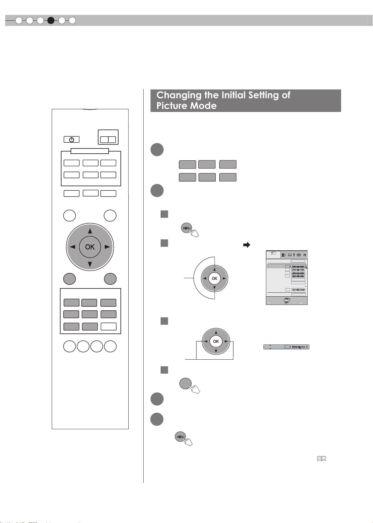
4
Changing the Initial Setting of
Picture Mode
Settings
Customizing Projected Images
You can adjust the projected image to a desired image quality and register the adjusted value. (Picture
Mode) Besides the ve default “Cinema 1”, “Cinema 2”, “Cinema 3”, “Natural”, “Stage”, “Dynamic” and “THX”
settings, there are 2 more types of user-dened settings for Picture Mode.
“Contrast”, “Brightness”, “Color”, “Tint”, “Color Temp.”, “Gamma”, “Sharpness”,
STAND BY
ON
“NR”, “CTI”, “Lens aperture” and “Clear Motion Drive” are registered in the
Picture Mode.
HDMI 1
VIDEO
LENS
TEST
MENU
PICTURE MODE
CINEMA
1
NATURAL
USER1
INPUT
HDMI 2
S-VIDEO
ASPECT
CINEMA
2
STAGE
USER2
COMP.
PC
HIDE
LIGHT
BACK
CINEMA
3
DYNAMIC
THX
Select picture mode
1
CINEMA
1
NATURAL
Adjust picture quality
2
CINEMA
2
STAGE
CINEMA
3
DYNAMIC
Example: To adjust “Contrast”
1
Display the setting menu
MENU
2
Select “Picture Adjust”
“Contrast”
Select
3 Adjust the setting
Picture Adjust
Picture Mode
Contrast
Brightness
Color
Tint
Color Temp.
Gamma
Advanced
Lens Aperture
Exit
MENU
Select
Natural
0
0
0
0
6500K
Normal
0
Reset
Operate
Back
BACK
LENS.
GAMMA C.TEMP
42
AP.
PIC.
ADJ.
Contrast
Adjust
4 To end the adjustments
BACK
Other items can also be adjusted
3
To end
4
MENU
● “Color Temp.”, “Gamma”, and “Lens aperture” can
also be adjusted from the remote control. (
0
P14)
Page 43

ENGLISH
Registering User-dened Picture Mode
Registering User-dened Picture Mode
from the Menu
Getting Started
Select the picture mode
1
2
Adjust picture quality
● See “Changing the initial setting of picture Mode” for procedures
on adjusting the picture quality. (
3
To end
MENU
Adjust picture quality
1
● See “Changing the Initial Setting of Picture Mode” for procedures
on adjusting the picture quality. (
P42)
P42)
CAUTION
● Adjustment settings of image quality
will not be registered if other picture
mode is selected before registering
these settings.
Preparation
Basic Operation
2
Display the setting menu
MENU
3
Select “Picture Adjust” “Picture Mode
4
“Natural
1
Select
”
2
Confirm
Register the setting
Picture Adjust
Picture Mode
Contrast
Brightness
Color
Tint
Color Temp.
Gamma
Advanced
Lens Aperture
Exit
MENU
Select
0
0
0
0
0
Operate
Natural
6500K
Normal
Reset
Back
Settings
”
Cinemaˍ
Cinemaˎ
Cinemaˏ
Natural
Stage
Dynamic
Userˍ
Userˎ
THX
BACK
Troubleshooting
Others
43
Page 44

5
Troubleshooting
Troubleshooting
Before sending the unit to your authorized dealer for repair, please check the following points.
The following situations are not malfunctions.
■
You do not need to worry about the following situations if there is no abnormality on the screen.
● Part of the top surface or front of the unit is hot.
● A creaking sound is heard from the unit.
● An operating sound is heard from the inside of the unit.
● Color smear occurs on some screens.
■
Perform the following operations when the unit is unable to operate normally due to external static or
noise.
When the unit is in standby mode, please pull out the power plug, then insert again.
1
Press the power button on the unit to turn on the power again.
2
■
A sound may be heard when the lamp is off but there is no danger.
■
D-ILA device is manufactured using high-precision technology but there may be some
missing pixels or pixels that remain permanently lit up.
Power is not supplied
Is the power cord disconnected?
Is the lamp cover properly shut?
Is the lamp in Cool Down mode?
Insert the power cord (plug) rmly.
Remove the power plug when the unit is in standby mode and
close the lamp cover properly. After that, insert the plug again.
After the Cool Down mode is complete, turn on the power
again.
Projected image is dark
Check the lamp time on the information menu. Prepare a
Is the lamp near exhaustion?
new lamp unit or replace as soon as possible when the
lamp is near exhaustion.
The unit works when power is turned on but stops abruptly after a few minutes
Are the air inlets and exhaust
vent blocked?
Is the lter dirty?
Remove the power plug when the unit is in standby mode and
remove any blocking object. After that, insert the plug again.
Clean the lter.
Video image does not appear
Is the correct external input
selected?
Is the AV device properly
connected?
Is the power of the AV device turned
on?
Are the correct signals being
output from the AV device?
Is the setting of the input terminal
correct?
Is the video image temporarily
hidden?
Select the correct external input.
Connect the AV device properly.
Turn on the power of the AV device and play the video.
Set the AV device properly.
Set “COMP.” and “HDMI” in the setting menu according to
the input signal.
Press the [HIDE] button to display the video image again.
P24
P49
P25
P48 to 50
P12 to 13
P51
P24
P16 to 20
P24
P16 to 20
11
P35 P36 -
12
P25
The picture cannot be projected
Will the picture icker and become
invisible with HDMI input?
44
Please use a short HDMI cable.
P18
Page 45
ENGLISH
The image cannot output by HDMI terminal
“
Is the setup of
function
Even if the “Control with HDMI” function is “On”, there are still some devices cannot reveal image normally.
●
“Off”
Control with HDMI”
?
Set up the “Control with HDMI” function to “Off”.
Color does not appear or looks strange
P35 -
Getting Started
11
Is the image correctly adjusted?
Adjust “Color” and “Tint” in the setting menu.
Video image is fuzzy
Is the focus correctly adjusted? Adjust the focus.
Is the unit placed too near or too far away
from the screen?
Set the unit at a correct distance from the screen.
Video images are missing
Has setting been performed for
screen mask?
Is the display out of position?
Set “Mask” in the setting menu to “Off”.
Alter the “Picture Position” value in the setting menu to
ensure that images are not missing.
Remote control does not work
Are batteries installed correctly?
Are batteries exhausted?
Match the polarities ( or ) correctly when inserting
the batteries.
Replace with new batteries.
Is there an obstructive object
between the remote control and
Remove any obstructive objects.
remote sensor?
Is the remote control held too far
away from the unit?
Hold the remote control closer to the sensor when
using.
P31 -
04 05
P24
P21 to 22
P27,38 -
P36 -
15
P15
P15
P15
P15
20
Preparation
Basic Operation
Settings
Power is cut off suddenly
Has setting been performed for off
timer?
Set “Off Timer” in the setting menu to “Off”.
P41 -
37
Troubleshooting
Others
45
Page 46
5
Troubleshooting
What to Do When these Messages Are Displayed
Message Cause (Details)
COMP.
No Input
COMP.
Lamp replacement
Back
BACK
No device is connected to the input terminal.
The input terminal is connected but there is no signal.
Input the video signals.
A video signal that cannot be used in this unit has been input.
Input video signals that can be used.
* The names of input terminals such as COMP. will be displayed in yellow.
This message is displayed when the accumulated lamp time has
exceeded 2900 hours.
To clear the message, press the [Back] button.
Get ready a new lamp unit and replace as soon as possible. Reset the
lamp time after replacing the lamp. (
P48 to 50
)
46
Page 47
ENGLISH
About Warning Indicators
The accumulated lamp time or warning mode of this unit is displayed by the indicators.
For information on indicator display during normal operation, see “Controls and Features”. (
Indicator
No.
WARNING LAMP STANDBY/ON
10
11
12
13
14
15
16
17
1
2
3
4
5
6
7
8
9
- -
- -
- -
- -
-
-
Light on
(Red)
Blinking
(Red)
Light on
(orange)
Light on
(orange)
Blinking
(orange)
Blinking
(orange)
Light on (Red)
Blinking (Red)
-
Blinking
Time
Blinking
Frequency
- - -
Light on
(Green)
Blinking
(Green)
- - -
0.5
second
0.5
second
continuous
continuous
- - - -
- - - -
0.25
second
-
-
0.25
second
0.25
second
0.25
second
0.25
second
0.25
second
0.25
second
0.25
second
0.25
second
0.25
second
0.25
second
1 time
2 times
3 times
1 time
2 times
3 times
4 times
1 time
2 times
3 times
4 times
Interval
between
Blinks
-
-
0.75
second
0.75
second
0.75
second
0.75
second
0.75
second
0.75
second
0.75
second
0.75
second
0.75
second
0.75
second
0.75
second
Content
During standby
When the power on
(Hide Off)
When the power on
(Hide On)
During cool down
Lamp replacement is near (
(When accumulated lamp time has
exceeded 2900 hours)
Lamp has reached the end of life
(
P48 to 50
(When accumulated lamp time has
exceeded 3000 hours)
Lamp does not light up and unit is
unable to project
Lamp is turned off during projection
Lamp cover is removed
Abnormalities in the power supply
Cooling fan stops
(cooling fan gets caught)
Internal temperature is too high
(abnormal internal temperature)
External temperature is too high
(abnormal external temperature)
Abnormal electrical circuit
(abnormal startup of drive circuit)
Abnormal electrical circuit
(abnormal communication of the
drive circuit)
Abnormal electrical circuit
(abnormal drive circuit of image)
Abnormalities in the automatic lens cover
)
P12
Indicator
display
in normal
conditions.
P48 to 50
Getting Started
)
Preparation
)
Basic Operation
Settings
Troubleshooting
Actions to Be Taken for Warning Mode
When the unit enters into warning mode (No. 7 to 17), it will automatically stop projection, and run the cooling
fan for about 60 seconds.
After the cooling fan has stopped, pull out the power plug from the power outlet.
Then, follow the procedures below.
No. Check Action
7
8
9
17
10
11
12
13
14
15
16
If the warning indication is displayed again, please wait for the cooling fan stopped, then pull out the power plug from the power outlet.
Then call your authorized dealer for repair.
Check that an impact shock has not occurred during operation.
●
Check that the lamp unit and lamp cover are correctly installed.
●
Check that nothing is blocking the auto lens cover.
●
Check that nothing is blocking the air inlets.
●
Check that the external temperature is normal.
●
Turn on the power again.
Leave the unit until it cools down.
After that, turn on the power again.
Others
47
Page 48
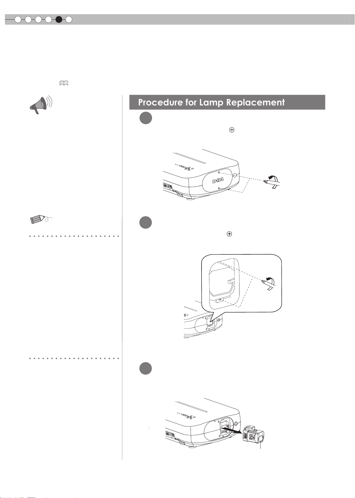
5
Procedure for Lamp Replacement
Troubleshooting
Replacing the Lamp
The lamp is a consumable item. If the image is dark or the lamp is turned off, replace the lamp unit.
● When the lamp replacement time approaches, a message is displayed on the screen and the condition is indicated by the
indicator. (
Pull the power plug from the power
●
outlet. Failure to do so may cause
injuries or electric shocks.
Do not replace the lamp immediately
●
after the unit has been used, and
allow a cooling period of 1 hour
or more before replacement. The
temperature of the lamp is still high
and this may cause a burn.
Do not apply shock to the lamp unit.
●
It may cause lamp blowout.
Do not use ammable air duster to
●
clean the internal parts of the unit.
This may cause re.
P46, 47)
CAUTION
1
Remove the lamp cover
●
Remove the screws with a screwdriver.
MEMO
Usable Lamp Life
When using the “Lamp Power” set
●
at “Normal”, the lifetime of the lamp
will be approximately 3000 hours.
This is an average lifetime and
cannot be guaranteed.
The lamp life may not reach
●
3000 hours depending on the
operating conditions.
When the lamp has reached the
●
end of its usable life, deterioration
progresses rapidly.
If the picture becomes dark, the tint
●
becomes strange, or the image
ickers, promptly the lamp unit for a
new one.
Purchasing the Lamp Unit
Please consult your authorized dealer.
■
Lamp Unit
Part No.: BHL5010-S
Loosen the screws on the lamp unit
2
●
Loosen the screws with a screwdriver.
3
Pull out the lamp unit
●
Grasp the handle and pull out the lamp unit.
48
Handle
Page 49

Install the new lamp unit
4
Handle
ENGLISH
CAUTION
Use only genuine replacement parts
●
for the lamp unit. Also, never attempt
to reuse an old lamp unit. This may
cause a malfunction.
Do not touch the surface of a new lamp.
●
This may shorten the lamp life and
cause lamp blowout.
MEMO
Getting Started
Preparation
Tighten the screws of the new
5
lamp unit
●
Tighten the screws with a screwdriver.
6
Attach the lamp cover
●
Insert the top part (with 2 claws) of the lamp cover into
the unit.
●
Fasten the screws with a screwdriver.
After Replacing the Lamp
Do not place the removed lamp unit at
●
locations that is reachable by children
or near combustible items
Dispose used lamp units in the same
●
way as uorescent lamps. Follow your
local community rules for disposal.
.
Basic Operation
Settings
Troubleshooting
Others
49
Page 50
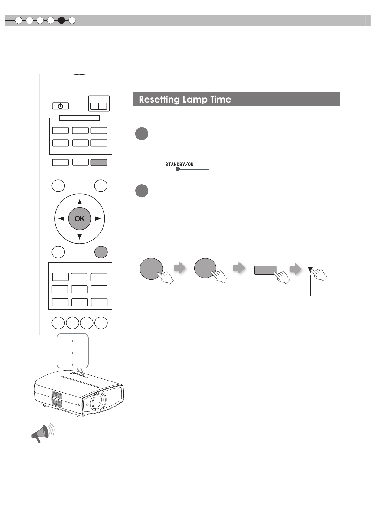
5
Resetting Lamp Time
Troubleshooting
Replacing the Lamp (Continued)
STAND BY
HDMI 1
VIDEO
LENS
TEST
MENU
PICTURE MODE
CINEMA
1
NATURAL
USER1
INPUT
HDMI 2
S-VIDEO
ASPECT
CINEMA
2
STAGE
USER2
ON
COMP.
PC
HIDE
LIGHT
BACK
CINEMA
3
DYNAMIC
THX
After replacing the lamp, reset the lamp time.
Insert the power plug to the power
1
outlet
Light on (Red)
2
Must operate with the remote control
in the standby mode (the projector is
powered, but is not turned on).
Press in the order as shown.
●
Press each button within 2-second intervals and press the last
●
button for 2 seconds or more.
BACK
OK
HIDE
Press for 2 seconds or more
LENS.
GAMMA
C.TEMP
W ARNING
LAMP
ST ANDBY/ON
AP.
PIC.
ADJ.
CAUTION
Reset the lamp time only when you
●
have replaced the lamp.
Never reset the service time when
●
the lamp is still in use. Otherwise,
the approximate standard for gauging
replacement time may be inaccurate
and lamp blowout may occur.
[STANDBY/ON] indicator and [LAMP] indicator blink alternately for
●
3 seconds. After that, the unit switches to standby mode.
50
Page 51

ENGLISH
Cleaning and Replacing the Filter
Clean the lter regularly or air intake efciency may deteriorate and malfunction may occur.
Remove the inner lter
1
CAUTION
Getting Started
Lift up while pushing the claw
Clean the lter
2
Wash the lter with water and dry it in a shaded area.
●
In extremely soiled cases, using a neutral detergent is recommended.
●
Put on rubber gloves when using a neutral detergent.
After washing the lter with water, make sure that it is completely dry
●
before reinstalling. Otherwise electric shock or malfunctions may occur.
Do not clean the lter with a vacuum cleaner or air duster. The lter is
●
soft and may be damaged.
Pull the power plug from the power
●
outlet.
Preparation
Basic Operation
MEMO
If the lter is damaged or too
dirty to be cleaned
Replace with a new lter. A dirty lter
●
will dirty the internal parts of the unit
and cause shadows on the video
image.
To purchase a new lter or when it
●
is dirty in the internal parts, consult
your authorized dealer.
■
Inner Filter Part No.:
Replacement Filter:
the appearance is black
PB006560999 (Inner Filter)
Settings
Troubleshooting
Reinstall the inner lter
3
Check that the left
and right claws are
locked onto the unit
Others
51
Page 52
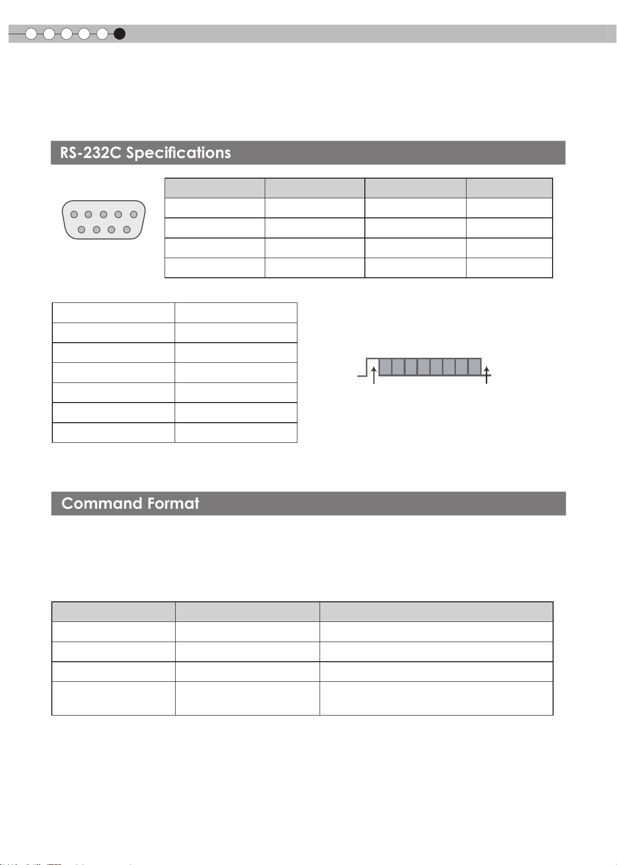
Others
Command Format
RS-232C Specications
6
RS-232C Interface
Control of this unit via a computer is possible by connecting the computer to this unit with a RS-232C
cross cable (D-Sub 9 pin).
This unit
Pin No. Signal Function Signal Direction
2 RxD Receive data PC→This unit
3 TxD Transmit data This unit→PC
5 GND Signal ground -
1,4,6 - 9 N/C - -
● PC refers to the controller such as a personal computer.
Mode
Character Length
Parity
Start Bit
Stop Bit
Data rate
Data format
Non-synchronous
8 bit
None
1
1
19200 bps
Binary
D6 D7D4 D5D2 D3D0 D1
Start Bit Stop Bit
The command between this unit and the computer consists of “Header”, “Unit ID”, “Command”, “Data” and “End”.
● Header (1 byte), Unit ID (2 bytes), Command (2 bytes), Data (n bytes), End (1 byte)
■
Header
This binary code indicates the start of communication.
Binary code Type Description
21 Operating command PC→This unit
3F Reference command PC→This unit
40 Response command This unit→PC
This unit→PC
06 ACK
■
Unit ID
This code species the unit. The binary code is xed at “8901”.
(When the command is accepted without error, it returns to
PC)
52
Page 53

■
Command and data
Operating command and data (Binary code)
Command Type Data description
0000 Connection check
5057 Power supply
4950 Input
5243 Remote Control
Check whether communication is available between this unit
and the PC during standby.
During standby
31: Turn on the power.
During power on
30: Turn off the power. (Standby mode)
During power on
30: S-VIDEO
31: VIDEO
32: COMP.
33: VGA
36: HDMI 1
37: HDMI 2
Sends the same code as the supplied remote control.
Remote control code” (
●
“
ENGLISH
Getting Started
Preparation
Basic Operation
P54)
Reference command and data (Binary code)
Command Type Data description
During standby or power on
30: Standby mode
5057 Power supply
4950 Input
■
End
This code indicates the end of communication. The binary code is xed at
31: Power-on mode
32: During Cool Down mode
34: Warning mode
During power on
30: S-VIDEO
31: VIDEO
32: COMP.
36: HDMI 1
37: HDMI 2
“0A”.
Settings
Troubleshooting
Others
53
Page 54

Others
6
RS-232C Interface (Continued)
■
Remote control code
Binary code is sent during communication.
●
Remote control button
name
BACK 37 33 30 33 STAGE 37 33 36 37
ON 37 33 30 35 CINEMA 2 37 33 36 38
STAND BY 37 33 30 36 CINEMA 1 37 33 36 39
HIDE 37 33 31 44 NATURAL 37 33 36 41
LENS.AP. 37 33 32 30 DYNAMIC 37 33 36 42
MENU 37 33 32 45 USER 1 37 33 36 43
OK 37 33 32 46 USER 2 37 33 36 44
LENS 37 33 33 30 THX 37 33 36 46
MENU POSITION 37 33 34 32 PIC.ADJ. 37 33 37 32
PC 37 33 34 36 GAMMA 37 33 37 35
Binary code
37 33 30 31 TEST 37 33 35 39
37 33 30 32 CINEMA 3 37 33 36 36
37 33 33 34 HDMI 1 37 33 37 30
37 33 33 36 HDMI 2 37 33 37 31
Remote control button
name
Binary code
VIDEO 37 33 34 41 C.TEMP 37 33 37 36
S-VIDEO 37 33 34 42 ASPECT 37 33 37 37
COMP. 37 33 34 43
54
Page 55

RS-232C Communication Examples
This section shows the communication examples of RS-232C.
■
Operating command
Type Command Description
Connection check
Power (On)
Power (Off)
Input (COMP.)
Remote Control
(MENU)
■
Reference command
PC→This unit: 21 89 01 00 00 0A
This unit→PC: 06 89 01 00 00 0A
PC→This unit: 21 89 01 50 57 31 0A
This unit→PC:
PC→This unit: 21 89 01 50 57 30 0A
This unit→PC: 06 89 01 50 57 0A
PC→This unit: 21 89 01 49 50 32 0A
This unit→PC:
PC→This unit: 21 89 01 52 43 37 33 32 45 0A
This unit→PC:
06 89 01 50 57 0A
06 89 01 49 50 0A
06 89 01 52 43 0A
ENGLISH
Connection check
When power is turned on from standby
mode
When power is turned off (standby mode)
from power-on mode
When video input is set to component
When the same operation as pressing
the [MENU] button on the remote control
is made
Getting Started
Preparation
Basic Operation
Type Command Description
Power (On)
Input (S-VIDEO)
PC→This unit: 3F 89 01 50 57 0A
This unit→PC: 06 89 01 50 57 0A
This unit→PC: 40 89 01 50 57 31 0A
PC→This unit: 3F 89 01 49 50 0A
This unit→PC: 06 89 01 49 50 0A
This unit→PC: 40 89 01 49 50 30 0A
When information of power-on mode is
acquired
When information of S-VIDEO input is
acquired
Settings
Troubleshooting
Others
55
Page 56

Others
About Trademarks and Copyrigh
t
Caution
6
Copyright and Caution
HDMI, HDMI logo and high denition multimedia interface
●
are trademarks or registered trademarks of HDMI Licensing
LCC.
D-ILA Device Characteristics
Do not project still pictures or pictures that have still
segments for a long period of time. The still parts of the
picture may remain on the screen.
Take special notice of images on the screens of video
games and computer programs. There is no problem when
playing normal video images such as movies.
When Unit is Unused for a Long
Time
Prolonged disuse of the unit may effect an error on the
functions. Turn on the power occasionally and operate the
unit.
Usage Environment
Avoid direct exposure of screen to direct sunlight and
●
illumination. Block light using a curtain. Images can be
well projected by darkening the brightness of the room.
Do not use this unit in rooms with cigarette smoke or oily
●
smoke. This may cause the unit to malfunction.
Parts Replacement
Maintenance Procedures
Dirt on the cabinet
Gently clean dirt on the cabinet with a soft cloth. In the case
●
of heavy soiling, soak a cloth in water, wring dry and wipe,
followed by wiping again with a dry cloth. Pay attention to
the following as the cabinet may deteriorate in condition or
paint may come off.
● Do not wipe with thinner or benzene.
● Do not spray with volatile chemicals like insecticide.
● Do not allow prolonged contact with rubber or plastic
products.
Dirt in the air inlets
Use a vacuum cleaner to suck up the dirt. Otherwise, use a
●
cloth to wipe off the dirt. If dirt is allowed to accumulate in
the air inlets, the internal temperature cannot be adjusted
and this may cause a malfunction.
Dirt on the lens
● Clean the dirt using commercial blowers or lens cleaning
papers for cleaning glasses and cameras. Do not use
uid-type cleaning agents. This may lead to peeling of the
surface coating lm. ( P13)
This unit contains parts (optical part, cooling fan, etc.) that
require replace ment to maintain its functi oning. T he
est i m a ted time for parts replacement varies gr e a t l y
depending on the usage and environment. Please consult
your authorized dealer for replacement.
56
Page 57
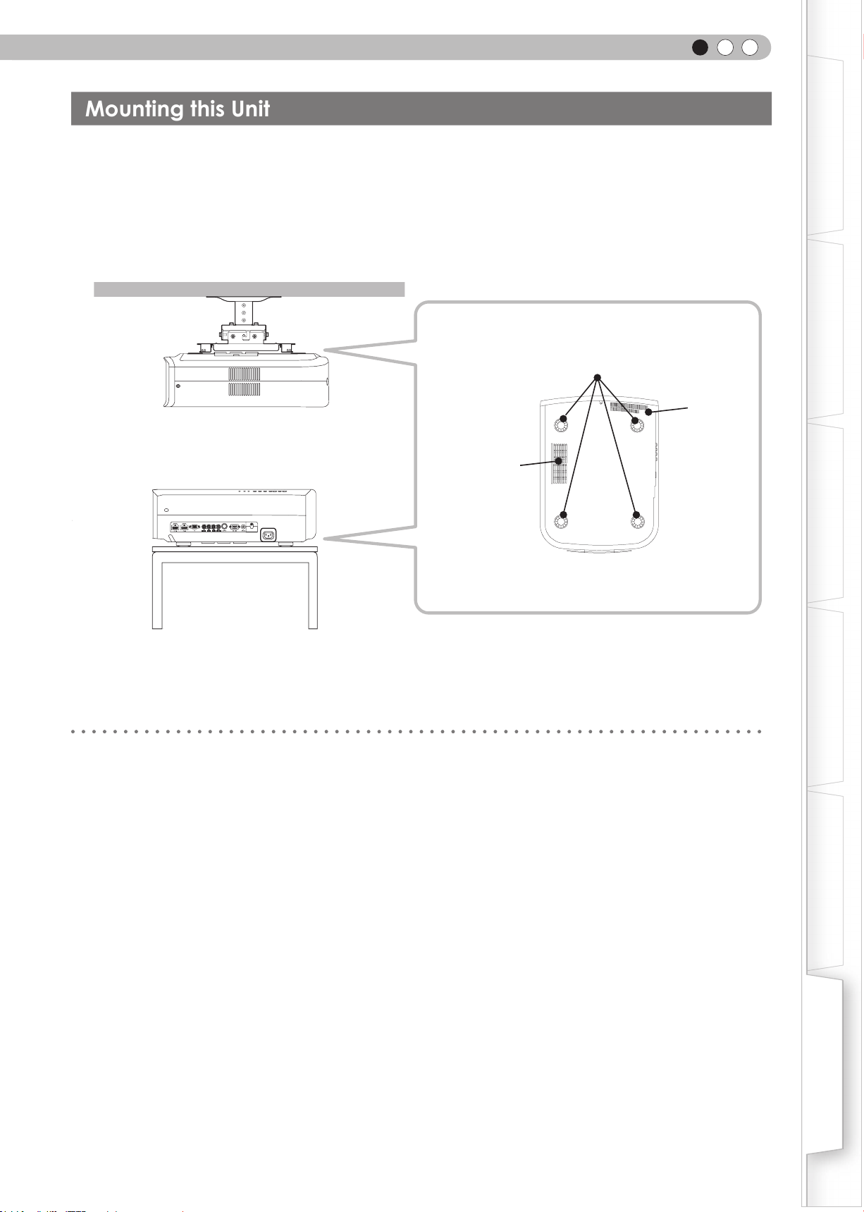
ENGLISH
Mounting this Unit
Measures to prevent the unit from toppling or dropping should be taken for safety reasons and accident
prevention during emergencies including earthquakes.
When mounting this unit on a pedestal or ceiling, remove the 4 feet on the bottom surface and use all the 4
screw holes (M5 screws) to mount.
Ceiling
■
Bottom Surface
4 locations
Air inlets
Air inlets
Getting Started
Preparation
Basic Operation
SYNC
Precautions for Mounting
Special expertise and techniques are required for mounting
●
this unit. Be sure to ask your dealer or a specialist to
perform mounting.
Depth of the screw holes (screw length) is 23 mm. Use
●
screws shorter than 23 mm but longer than 13 mm.
Using other screws will result in
malfunctioning or cause the unit to drop.
When mounting to a pedestal, ensure sufcient space
●
(foot height of 10 mm or higher) around the unit so that
the air inlets are not blocked.
Do not tilt this unit more than ±5 degrees from side to
●
side when using.
Regardless whether the unit is still under guarantee,
●
JVC is not liable for any product damage caused by
mounting the unit with non-JVC ceiling ttings or when
the environment is not suitable for ceiling-mount.
When using the unit hanging from a ceiling, pay
●
attention to the surrounding temperature. When a
heater is in use, temperature around the ceiling is
higher than expected.
Settings
Troubleshooting
Others
57
Page 58

Others
6
Specications
Product Name
Model Name
Display Panel/Size
Projection Lens
Light-source Lamp
Screen Size
objection Distance
Color System
Analog Video Input Format
Digital Video Input Format
Resolution
Color Management
Terminals
Video Input
(
VIDEO
)
S-video Input
(
S-VIDEO
)
Component Video Input
COMPONENT
(
)
HDMI Input
(
HDMI 1, HDMI 2
)
PC Input
D-ILA Projector
DLA-HD950 / DLA-HD990
D-ILA device
0.7" (1920pixels x 1080pixels) x 3 (Total no. of pixels: Approx. 6.22million)
2.0 x power zoom lens (1.4:1 to 2.8:1)(Zoom/Focus: Power)
200 W Ultra-high pressure mercury lamp [Part No. : BHL5010-S]
Average lifespan: 3000 hours (normal mode)
Approx. 60" to 200" (Aspect ratio: 16:9)
Approx. 1.8m to 12m
NTSC, NTSC4.43, PAL, PAL-M, PAL-N, SECAM (Auto/Manual switch)
480i, 480p, 576i, 576p, 720p/50Hz, 720p/60Hz, 1080i/50Hz, 1080i/60Hz
480i, 480p, 576i, 576p, 720p/50Hz, 720p/60Hz, 1080i/50Hz, 1080i/60Hz,
1080p/24Hz, 1080p/50Hz, 1080p/60Hz, PC compatible signals ( P59)
1920 dots x 1080 dots
Featured
1-line, RCA pin jack x 1
1.0V(p-p), 75Ω
1-line, mini DIN 4 pin x 1
Y: 1.0V(p-p), 75Ω
C: 0.286V(p-p), 75Ω(NTSC); 0.3V(p-p), 75Ω(PAL)
1-line, RCA pin jack x 3
Y: 1.0V(p-p), 75Ω
CB/PB, CR/PR: 0.7V(p-p), 75Ω
2-line, HDMI 19 pin x 2(HDCP compliant)
Compatible with the HDMIv1.3a standard
1-line, D-Sub 15 pin VGA
*1 *2
/
*3
Trigger Output
Power Requirements
Power Consumption
Operation Environment
Installation Height
Dimensions
(Width x Height x Depth)
Mass
Accessories
*1 D-ILA is the abbreviation for Direct drive Image Light Amplier.
*2 D-ILA devices are manufactured using extremely high-precision technology. Pixel effectiveness is 99.99%. Only 0.01% or
less of the pixels are either missing or would remain permanently lit up.
*3 HDCP is the abbreviation for High-bandwidth Digital Content Protection system.
The image of HDMI input terminal may not be displayed due to HDCP specication change.
12V 100mA
AC 110V-240V 50/60 Hz
310W (Standby mode: 0.7W)
Temperature: 5℃ to 35
Humidity: 20% to 80% (No condensation)
(Storage Temperature: -10℃ to 60℃)
Below 1524m
365mm X 167mm X 477.5mm
11.2kg
(See
P11
)
℃
● Design and specications are subject to change without prior notice.
● Please note that some of the pictures and illustrations may have been abridged, enlarged or contextualized in order to aid
comprehension. Images may differ from the actual product.
58
Page 59

ENGLISH
■
PC compatible signals
HDMI
●
No.
Designation Resolution
1 VGA 60 640 X 480 31.500 60.000 25.200 - - 800 525 640 480
fh
[kHz]
fv
[Hz]
Dot CLK
[MHz]
H V
Polarity
Total No.
of dots
[dot]
Total No.
of lines
[line]
No. of
effective
dots
[dot]
Getting Started
No. of
effective
lines
[line]
2 VGA 59.94 640 X 480 31.469 59.940 25.175 - - 800 525 640 480
3 SVGA 60 800 X 600 37.879 60.317 40.000 + + 1,056 628 800 600
4 XGA 60 1024 X 768 48.363 60.004 65.000 - - 1,344 806 1,024 768
5 WXGA 60 1280 X 768 47.760 60.000 79.998 - + 1,675 796 1,280 768
6 WXGA +60 1440 X 900 55.919 59.999 106.470 - + 1,904 932 1,440 900
7 SXGA 60 1280 X 1024 63.981 60.020 108.000 + + 1,688 1,066 1,280 1,024
8 WSXGA +60 1680 X 1050 65.222 60.002 147.140 - + 2,256 1,087 1,680 1,050
9 WUXGA 60 1920 X 1200 74.038 59.95 154.000 + - 2,080 1,235 1,920 1,200
Images may not be displayed if the above timings are not met.
PC (D-sub 3-lines 15 pins)
●
No.
Designation Resolution
1 VGA 60 640 X 480 31.500 60.000 25.175 - - 800 525 640 480
2 VGA 72 640 X 480 37.900 72.000 31.500 - - 832 520 640 480
3 VGA 75 640 X 480 37.500 75.000 31.500 - - 840 500 640 480
4 VGA 85 640 X 480 43.300 85.000 36.000 - - 832 509 640 480
5 SVGA 56 800 X 600 35.200 56.000 36.000 + + 1024 625 800 600
6 SVGA 60 800 X 600 37.900 60.000 40.000 + + 1056 628 800 600
7 SVGA 72 800 X 600 48.100 72.000 50.000 + + 1040 666 800 600
8 SVGA 75 800 X 600 46.900 75.000 49.500 + + 1056 625 800 600
9 SVGA 85 800 X 600 53.700 85.000 56.250 + + 1048 631 800 600
10 XGA 60 1024 X 768 48.400 60.000 65.000 - - 1344 806 1024 768
11 XGA 70 1024 X 768 56.500 70.000 75.000 - - 1328 806 1024 768
12 XGA 75 1024 X 768 60.023 75.029 78.750 + + 1312 800 1024 768
13 XGA 85 1024 X 768 68.700 85.000 94.500 + + 1376 808 1024 768
14 WXGA 60 1280 X 768 47.760 60.000 79.998 - + 1675 796 1280 768
15 WXGA+ 60 1440 X 900 55.919 59.999 106.470 - - 1904 932 1440 900
16 SXGA 60 1280 X 1024 63.981 60.020 108.000 + + 1688 1066 1280 1024
17 SXGA+ 60 1400 X 1050 64.740 59.950 101.000 + + 1560 1080 1400 1050
18 WSXGA+ 60 1680 X 1050 65.222 60.002 147.140 - - 2256 1087 1680 1050
19 1920x1080 60
20 MAC13"
21 MAC16"
22 MAC19"
Images may not be displayed if the above timings are not met.
1920 X 1080
640 X 480
832 X 624
1024 X 768
fh
[kHz]
67.500 60.00 148.500 + + 2200 1125 1920 1080
35.000 66.667 30.240 - - 864 525 640 480
49.107 75.087 55.000 - - 1120 654 832 624
60.241 74.927 80.000 - - 1328 804 1024 768
fv
[Hz]
Dot CLK
[MHz]
H V
Polarity
Total No.
of dots
[dot]
Total No.
of lines
[line]
No. of
effective
dots
[dot]
effective
Preparation
Basic Operation
No. of
lines
[line]
Settings
Troubleshooting
Others
59
Page 60
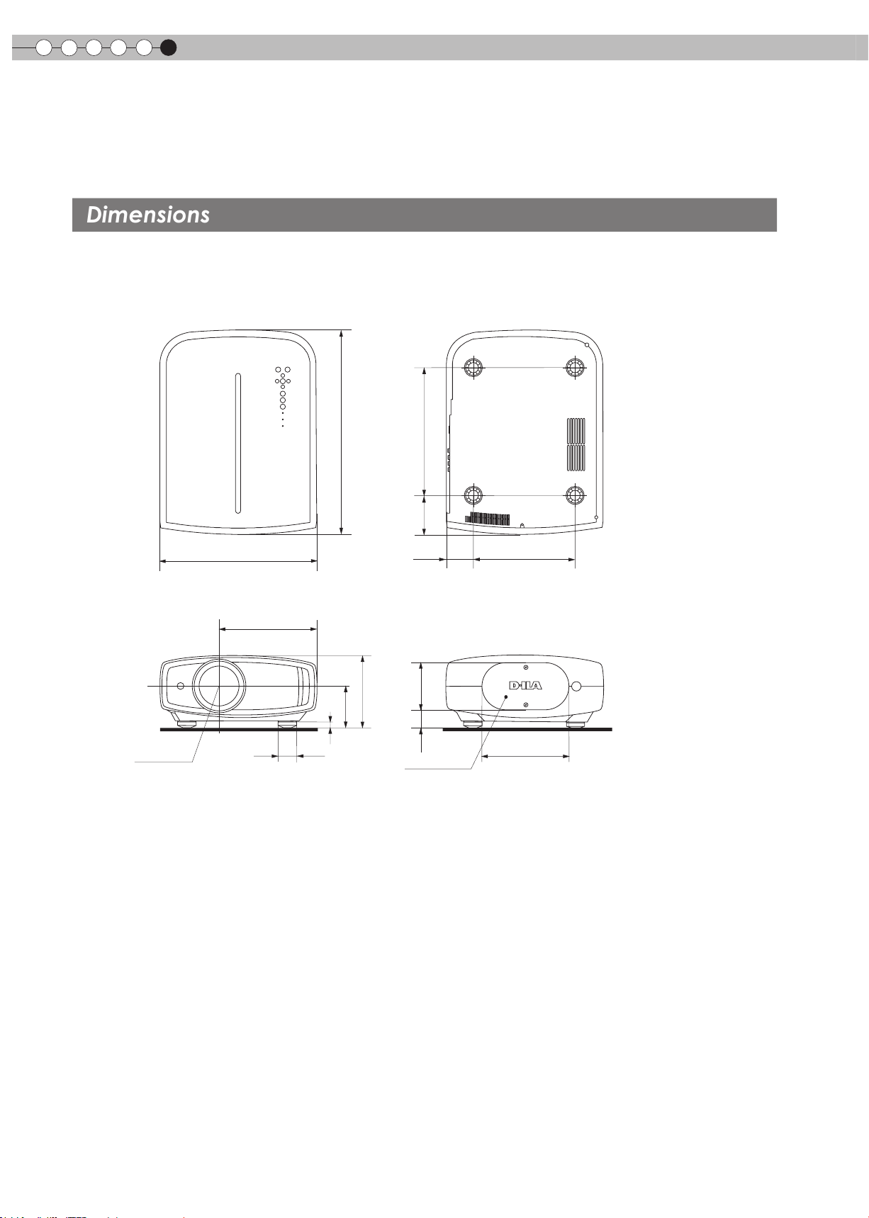
Others
Dimensions
6
Specications(Continued)
■
Top Surface
■
Front
365
225.4
477.5
95
167
■
Bottom Surface
297
90.6
64.5
■
Back Surface
(Unit: mm)
236
Lens center
Φ42
12
42.5 105
Lamp cover
198
60
Page 61

Index
HDMI
LED
Screen size
Mask
Batteries
Shift
Zoom
Installation
Standard ............................................Page 58
Connecting .......................................... Page 18
Settings ........................................ Page 35
Warning ..............................................Page 47
Distance Chart ...................................Page 22
Settings ...............................................Page 26
Settings ..............................................Page 27
Types ................................................. Page 11
Shift Amount .......................................Page 21
Adjustment ................................... Page 25
Adjustment .........................................Page 24
Angle ..................................................Page 21
Settings ............................................. Page 28
Caution .................................................Page 2
Ceiling Mount ................................. Page 2,57
ENGLISH
Getting Started
Preparation
Basic Operation
Settings Menu
Structure ............................................Page 28
Projection Distance
Distance Chart ...................................Page 22
Input Signal
PC Compatibility .................................Page 59
Video Compatibility ...................... Page 58
Filter
Air Intake Filter ...................................Page 13
Replacement Filter Number ..........Page 11,51
Cleaning and Replacement ................Page 51
Focus
Adjustment .........................................Page 24
Message
Meaning .............................................Page 46
Lamp
Replacement ......................................Page 48
Replacement Lamp Number .........Page 11,48
Resetting the Time .............................Page 50
Notes of Caution ................................. Page 3
Remote Control
Instructions ....................................Page 14,15
Settings
Troubleshooting
Others
61
Page 62

Others
6
MEMO
62
Page 63

FRANÇAIS
MANUEL D’INSTRUCTIONS
PROJECTEUR D-ILA
DLA-HD950/DLA-HD990
Pour commencer
Préparation
Fonctionnement
Réglages
Dépannage
Autres
Page 64
1
-
-
-
-
-
-
-
-
-
-
-
-
Afin de permettre une meilleure dissipation de la chaleur ,
laissez un espace libre tout autour de cet appareil, tel
qu’illustré ci-dessous. Lorsque cet appareil se trouve dans
un espace dont les dimensions correspondent à celles
indiquées ci-dessous, utilisez un climatiseur pour que la
température soit la même à l’intérieur et à l’extérieur de cet
espace. La surchauffe peut causer des dommages.
-
-
-
-
-
-
-
-
Cet appareil est équipé d’une fiche à trois broches. Elle ne
peut être branchée que dans une prise secteur avec mise à
la terre. Si vous ne pouvez pas insérer la fiche dans la prise,
contactez votre électricien afin qu’il installe une prise
correcte. N’essayez pas de défaire le principe de sécurité de
la fiche avec mise à la terre.
Les cordons d’alimentation doient être positionnés de façon
à ce qu’ils ne soient pas écrasés ou coincés par des objets
placés sous ou contre eux. Faites particulièrement attention
aux cordons au niveau des portes, des fiches et prises ainsi
qu’au niveau de la sortie de l’appareil.
Pour une meilleure protection pendant un orage ou quand il
est laissé sans surveillance ou n’est pas utilisé pendant une
longue période de temps, débranchez-le de la prise secteur
murale et déconnectez le système de câbles. Cela évitera
qu’il soit endommagé du fait d’un éclair ou d’une surtension
.
Ne surchargez pas les prises murales, les cordons prolonga-
teurs ou les prises de courant sur les autres appareils car
cela pourrait entraîner un risaue d’incendie ou
d’électrocution.
Ne jamais insérer d’objet d’aucune sorte à l’intérier de cet
appareil à travers les ouvertures car ils pourraient toucher
des points de tension dangeureuse ou créer un court circuit
qui pourrait entraîner un incendie ou une éléctrocution. Ne
jamais verser de liquide d’aucune sorte sur l’appareil.
N’essayez pas de réparer cet appareil vous-même car
l’ouvrir ou retirez les couvercles peut vous exposer à des
tensions dangeureuses ou à d’autres dangers. Référezvous
à un personnel qualifié pour toute réparation.
Débranchez l’appareil de la prise secteur murale et
contactez un réparateur qualifié dans les conditions
suivantes:
a) Quand le cordon ou la fiche d’alimentation secteur est
endomagé.
b) Si un liquide à coulé ou si un objet est tombé l’intérieur
de l’appareil.
c) Si l’appareil a été exposé à la pluie ou à l’eau.
d) Si l’appareil ne fonctionne pas normalement en suivant
les instructions de fonctionnement. Ajustez uniquement
les commandes couvertes par le mode d’emploi, car un
ajustement incorrect des commandes peut endommager
l’appareil et demandera souvent beaucoup de temps à
un technicien qualifié pour ramener l’appareil en état de
fonctionnement normal.
e) Si le produit est tombé ou a été endommagé de n’importe
quelle autre façon.
f ) Quand l’appareil montre un changement évident dans
ses performances, cela indique qu’il doit être réparé.
Quand le remplacement des pièces est nécessaire,
assurezvous que le réparateur a utilisé les pièces de
rechange spécifiées par le fabricant ou possédant les
mêmes caractéristiques que la pièce originale. Un
remplacement non autorisé peut entraîner in incendie,
une éléctrocution ou autres dangers.
Après que cet appareil a subi une réparation ou un
entretien, demandez au réparateur de réaliser les
vérifications de sécurité pour déterminer si l’appareil est
en état de fonctionnement correct .
L’ appareil doit être placé à plus de trente centimètres de
sources de chaleu r, comme un radiateu r, un accumula -
teur de chaleu r, un fourneau ou tout autre appareil
(amplificateurs inclus) produisant de la chaleu r.
Lors d’un raccordement avec un magnétoscope ou un
lecteur de DVD, vous devez mettre cet appareil hors
tension pour éviter tout choc électrique.
Ne placez pas de produits combustibles derrière le
ventilateur de refroidissement. Par exemple, du tissu,
du papier , des allumettes, une bombe aérosol ou un
briquet à gaz qui présentent des dangers particuliers
s’ils sont chau ff és.
Ne regardez pas dans l’objectif de projection quand la
lampe du projecteur est allumée. Une exposition des
yeux à une forte lumière peut af faiblir votre vue.
Ne regardez pas à l’intérieur de l’appareil au travers de
évents (orifices de ventilation), etc. Ner regardez pas
directement la lampe de projection en ouvrant le co ff ret
pendant que celle-ci est allumée. La lampe de projec-
tion émet aussi des rayons ultrviolets et la lumière est si
forte que votre vue pourrait être af faiblie.
Ne pas laisser tomber , frapper ou autrement endom -
mager la source de lumière (module lampe). La source
de lumière peut se briser et entraîner des blessures. Ne
jamais utiliser de lampe endommagée. Si la source de
lumière est cassée, demandez à votre revendeur
d’eefectuer la réparation. Des fragments provenants
d’une lampes brisée pourraient causer des blessures.
La lampe utiliser dans ce projecteur est une lampe au
mercure sous haute pression. Faire attention lorsque
cette lampe doit être jetée. S’il y a quelque chose que
vous ne comprenez pas, contactez votre revendeur .
N’ef fectuez pas de “montage au plafond” du projecteur
dans endroit soumis à beaucoup de vibrations. Les
fixations pourraient se défaire du fait des vibrations
causant ainsi la chute de l’appareil et une éventuelle
blessure physique .
Utilisez uniquement le cordon fourni conçu pour cet
appareil afin d’éviter tout choc éléctrique.
*NE LAISSEZ PA S une personne non qualifiée installer
l’appareil .
Demandez au revendeur d’installer l’appareil (par
exemple, la fixation au plafond) car cela demande des
connaissances et des techniques spéciales. Si
l’installation est réalisée par une personne non qualifiée,
cela pourrait entraîner des blessures personnelles ou une
éléctrocution .
Alimentation électrique indiquée sur l'étiquette. Si vous
n’êtes pas sûr du type d’alimentation électrique domestique,
consultez un revendeur ou votre entreprise locale de
distribution d’énergie.
Au moins
200 mm
Au moins
300 mm
Au moins
150 mm
Au moins 150 mm
Au moins
300 mm
SYNC
Importantes Mesures De Sécurité
Importantes Mesures De Sécurité
IMPORTANT INFORMATION
Ce p ro du it conmprend une lamp e à
dé ch ar ge à haute intensité (H ID )
co nt en an t du mercure.
Él iminer ces déc hets es t sujet à la
ré glement ation d e votre commun au té
po ur des raisons enviro nnement al es.
Po ur de p lus amp les inf ormatio ns
co ncernan t leur élimina tion ou l eur
re cyclage , veuil lez con tacter vo s
au torités locale s ou, p our les É -U,
l’ Electro nic Ind ustries Allian ce
ht tp://ww w.eiae. org.
AVERTISSEMENT:
POUR ÉVITER TOUT RISQUE D’INCENDIE OU
D’ÉLÉCTROCUTION, N’EXPOSEZ PAS CET APPAREIL À
LA PLUIE OU À L’HUMIDITÉ.
AVERTISSEMENT:
CET APPAREIL DOIT ETRE MIS A LA TERRE.
ATTENTION:
Pour réduire les risques d’électrocution, ne retirez pas le
couvercle de l’appareil. Référez-vous à un technicien
qualifié.
Ce projecteur est équipé d’une prise comprenant une fiche
de terre afin de respecter les règles du FCC. Si vous êtes
dans l’impossibilité d’insérer la prise dans la prise murale,
contactez votre électricien.
INFORMATIONS DU FCC (seulement aux É-U)
AVERTISSEMENT :
Les transformations ou les modifications n’étant pas
approuvées par JVC pourraient annuler le droit de
l’utilisateur d’utiliser l’équipement.
NOTE :
Cet équipement a été testé et a été reconnu comme
respectant les limites des appareils numériques de classe
B, conformément à la partie 15 des règles du FCC. Ces
limites sont conçues pour fournir une protection
raisonnable contre les interférences nuisibles. Cet
équipement génère, utilise et peut émettre de l’énergie
sous forme de fréquence radio et, s’il n’est pas installé et
utilisé en accord avec les instructions, il pourrait causer
des interferences nuisibles aux communications radio.
Néanmois, il n’y a aucune garantie que l’interférence
n’apparaitra pas dans une installation particulière. Si cet
équipement cause en effet des interférences nuisibles à la
réception radio ou TV, ce qui peut être vérifié en éteignant
et rallumant l’équipement, l’utilisateur est encouragé à
essayer de corriger l’interférence avec l’une ou plusieurs
des mesures suivantes
Réorientez ou déplacez l’antenne de reception.
ƽ
ƽAugmentez la distance entre l’équipement et le récepteur.
ƽConnectez l’équipement à une prise ou à un circuit électrique
différent de celui sur lequel le récepteur est branché.
ƽConsultez votre revendeur ou un technician expérimenté en
radio / TV pour de l’aide.
Pour commencer
o
:
o
:
INFORMATION CONCERNANT LES NUISANCES
SONORES DES MACHINES (seulement en Allemagne)
Modifie l’ordonnance 3. GSGV concernant les nuisances
sonores des machines du 18 janvier 1991 : Le niveau de
pression sonore à la position de l’utilisateur est inférieur
ou égal à 20 dB (A) conformément à l’ISO 7779.
À propos du choix de l’emplacement
N’installez pas le projecteur dans un endroit qui ne peut pas
soutenir son poids en toute sécurité.
Si l’emplacement de l’installation n’est pas suffisamment
solide, le projecteur risque de tomber ou de se renverser et
de blesser quelqu’un.
IMPORTANTES MESURES DE SÉCURITÉ
L’énergie électrique peut remplir beaucoup de fonctions utiles.
Cet appareil a été conçu et fabriqué pour assurer votre propre
sécurité. Mais UNE UTILISATION INCORRECTE PEUT
ENTRAÎNER UN RISQUE POTENTIEL D’ÉLECTROCUTION
OU D’INCENDIE. Afin de ne pas annuler les dispositifs de
sécurité incorporés dans cet appareil, observez les règles
fondamentales suivantes pour son installation, son utilisation
et sa réparation. Veuillez lire attentivement ces Importantes
mesures de sécurité avant d’utiliser l’appareil.
-
Toutes les instructions de sécurité et de fonctionnement
doivent être lues avant l’utilisation de l’appareil.
Les instructions de sécurité et de fonctionnement doivent
-
être conservées à titre d’information.
Tous les avertissements sur l’appareil et dans le mode
-
d’emploi doivent être compris et acceptés.
-
Toutes les instructions de fonctionnement doivent être suivies.
-
Mettre le projecteur près d’une prise de courant, de façon à
pouvoir le brancher et débrancher facilement.
Débranchez cet appareil de la prise murale avant de le
-
nettoyer. Ne pas utiliser de netoyyant ou en aérosol. Utilisez
un chiffon humide pour le nettoyage.
-
N’utilisez pas d’accessoires non recommandés par le fabricant
de l’appareil car ils pourraient être dangereux.
N’utilisez pas ce produit près de l’eau. Ne pas l’utiliser non plus
-
après l’avoir déplacé d’une basse température à une température élévée. Cela produit une condensation d’humidité qui peut
entraîner un incendie, une électrocution ou d’autres dangers.
Ne placez pas cet appareil sur un chariot, une table ou tout
-
autre support instable. L’appareil pourraît tomber, et ainsi
blesser gravement un enfant ou un adulte, ainsi qu’être ui
même sérieusement endommagé. L’appareil doit être monté
conformément aux instructions du fabricant et doit utiliser un
support recommandé par le fabricant.
-
Quand vous utilisez l’appareil sur un
chariot, faites attention aux arrêts brusques,
aux forces excessives et aux surfaces
accidentées qui pourraient causer un
renversement de l’appareil, risquant de
l’endommager ou de blesser l’opérateur.
-
Les fentes et les ouvertures du coffret sont nécessaires pour la
ventilation. Elles assurent un fonctionnement sûr de l’appareil
et le protège d’une surchauffe. Ces ouvertures ne doivent pas
être bloquées ou recouvertes. (Les ouvertures ne doivent
jamais être bloquées en plaçant l’appareil sur un lit, un divan,
un tapis ou une surface similaire. Il ne doit pas être encastré
dans un emplacement comme une bibliothèque ou un bâti sauf
si une ventilation correcte existe et si les instructions du
fabricant ont été respectées.)
2
Page 65

-
Afin de permettre une meilleure dissipation de la chaleur ,
laissez un espace libre tout autour de cet appareil, tel
qu’illustré ci-dessous. Lorsque cet appareil se trouve dans
un espace dont les dimensions correspondent à celles
indiquées ci-dessous, utilisez un climatiseur pour que la
température soit la même à l’intérieur et à l’extérieur de cet
espace. La surchauffe peut causer des dommages.
Au moins 150 mm
Au moins
300 mm
Au moins
150 mm
SYNC
-
Alimentation électrique indiquée sur l'étiquette. Si vous
n’êtes pas sûr du type d’alimentation électrique domestique,
consultez un revendeur ou votre entreprise locale de
distribution d’énergie.
-
Cet appareil est équipé d’une fiche à trois broches. Elle ne
peut être branchée que dans une prise secteur avec mise à
la terre. Si vous ne pouvez pas insérer la fiche dans la prise,
contactez votre électricien afin qu’il installe une prise
correcte. N’essayez pas de défaire le principe de sécurité de
la fiche avec mise à la terre.
-
Les cordons d’alimentation doient être positionnés de façon
à ce qu’ils ne soient pas écrasés ou coincés par des objets
placés sous ou contre eux. Faites particulièrement attention
aux cordons au niveau des portes, des fiches et prises ainsi
qu’au niveau de la sortie de l’appareil.
-
Pour une meilleure protection pendant un orage ou quand il
est laissé sans surveillance ou n’est pas utilisé pendant une
longue période de temps, débranchez-le de la prise secteur
murale et déconnectez le système de câbles. Cela évitera
qu’il soit endommagé du fait d’un éclair ou d’une surtension
-
Ne surchargez pas les prises murales, les cordons prolongateurs ou les prises de courant sur les autres appareils car
cela pourrait entraîner un risaue d’incendie ou
d’électrocution.
-
Ne jamais insérer d’objet d’aucune sorte à l’intérier de cet
appareil à travers les ouvertures car ils pourraient toucher
des points de tension dangeureuse ou créer un court circuit
qui pourrait entraîner un incendie ou une éléctrocution. Ne
jamais verser de liquide d’aucune sorte sur l’appareil.
-
N’essayez pas de réparer cet appareil vous-même car
l’ouvrir ou retirez les couvercles peut vous exposer à des
tensions dangeureuses ou à d’autres dangers. Référezvous
à un personnel qualifié pour toute réparation.
Débranchez l’appareil de la prise secteur murale et
-
contactez un réparateur qualifié dans les conditions
suivantes:
a) Quand le cordon ou la fiche d’alimentation secteur est
endomagé.
b) Si un liquide à coulé ou si un objet est tombé l’intérieur
de l’appareil.
c) Si l’appareil a été exposé à la pluie ou à l’eau.
d) Si l’appareil ne fonctionne pas normalement en suivant
les instructions de fonctionnement. Ajustez uniquement
les commandes couvertes par le mode d’emploi, car un
ajustement incorrect des commandes peut endommager
l’appareil et demandera souvent beaucoup de temps à
un technicien qualifié pour ramener l’appareil en état de
fonctionnement normal.
e) Si le produit est tombé ou a été endommagé de n’importe
quelle autre façon.
f ) Quand l’appareil montre un changement évident dans
ses performances, cela indique qu’il doit être réparé.
Au moins
300 mm
Au moins
200 mm
FRANÇAIS
Pour commencer
-
Quand le remplacement des pièces est nécessaire,
assurezvous que le réparateur a utilisé les pièces de
rechange spécifiées par le fabricant ou possédant les
mêmes caractéristiques que la pièce originale. Un
remplacement non autorisé peut entraîner in incendie,
une éléctrocution ou autres dangers.
-
Après que cet appareil a subi une réparation ou un
entretien, demandez au réparateur de réaliser les
vérifications de sécurité pour déterminer si l’appareil est
en état de fonctionnement correct .
-
L’ appareil doit être placé à plus de trente centimètres de
sources de chaleu r, comme un radiateu r, un accumula teur de chaleu r, un fourneau ou tout autre appareil
(amplificateurs inclus) produisant de la chaleu r.
-
Lors d’un raccordement avec un magnétoscope ou un
lecteur de DVD, vous devez mettre cet appareil hors
tension pour éviter tout choc électrique.
-
Ne placez pas de produits combustibles derrière le
ventilateur de refroidissement. Par exemple, du tissu,
du papier , des allumettes, une bombe aérosol ou un
briquet à gaz qui présentent des dangers particuliers
s’ils sont chau ff és.
-
Ne regardez pas dans l’objectif de projection quand la
lampe du projecteur est allumée. Une exposition des
yeux à une forte lumière peut af faiblir votre vue.
-
Ne regardez pas à l’intérieur de l’appareil au travers de
évents (orifices de ventilation), etc. Ner regardez pas
directement la lampe de projection en ouvrant le co ff ret
pendant que celle-ci est allumée. La lampe de projection émet aussi des rayons ultrviolets et la lumière est si
forte que votre vue pourrait être af faiblie.
-
Ne pas laisser tomber , frapper ou autrement endom mager la source de lumière (module lampe). La source
de lumière peut se briser et entraîner des blessures. Ne
jamais utiliser de lampe endommagée. Si la source de
lumière est cassée, demandez à votre revendeur
d’eefectuer la réparation. Des fragments provenants
d’une lampes brisée pourraient causer des blessures.
-
La lampe utiliser dans ce projecteur est une lampe au
mercure sous haute pression. Faire attention lorsque
cette lampe doit être jetée. S’il y a quelque chose que
.
vous ne comprenez pas, contactez votre revendeur .
-
N’ef fectuez pas de “montage au plafond” du projecteur
dans endroit soumis à beaucoup de vibrations. Les
fixations pourraient se défaire du fait des vibrations
causant ainsi la chute de l’appareil et une éventuelle
blessure physique .
-
Utilisez uniquement le cordon fourni conçu pour cet
appareil afin d’éviter tout choc éléctrique.
*NE LAISSEZ PA S une personne non qualifiée installer
l’appareil .
Demandez au revendeur d’installer l’appareil (par
exemple, la fixation au plafond) car cela demande des
connaissances et des techniques spéciales. Si
l’installation est réalisée par une personne non qualifiée,
cela pourrait entraîner des blessures personnelles ou une
éléctrocution .
Préparation
Fonctionnement
Réglages
Dépannage
Autres
3
Page 66

1
Importantes Mesures De Sécurité (Suite)
CONNEXION ELECTRIQUE
AVERTISSEMENT:
Ne débranchez pas la fiche principale de cet appareil.
AVERTISSEMENT:
CET APPAREIL DOIT ETRE MIS A LA TERRE.
Aux É-U et au Canada seulement.
N’utilisez que le cordon d’alimentation suivant.
Cord. d‘alimentation
Cord. d‘alimentation
Pour le Royaume-Uni
Pour les pays du continent
européen
La tension d’alimentation secteur de cet appareil est de
110V – 240V CA. N’utilisez que le cordon d’alimentation
désigné par nos revendeurs pour la sécurité et la compatibilité électromagnétique (EMC).
Assurez- vous que le cordon d’alimentation utilisé pour le
projecteur correspond bien au type de prise de votre pays.
Consultez votre revendeur.
Si la fiche existante ne convient pas aux prises de courant
de votre maison ou si le cordon est trop court pour atteindre
une prise de courant, procurez-vous un cordon prolongateur
ou un adapteur de sécurité approuvé ou consultez votre
revendeur.
Si la fiche secteur etait coupée, jetez la prise immédiatement, pour éviter tout danger d’électrocution par une
connexion accidentelle à l’alimentation secteur. Si la
nouvelle fiche secteur doit être adapté, suivez les instructions données ci-dessous.
CONNEXION ELECTRIQUE
(Royaume-Uni seulement)
REMPLACEMENT DU FUSIBLE:
Fusibles
Lors du remplacement du fusible, assurez-vous d’utiliser
seulement un fusible de valeur correcte et de type
approuvé. Remettez en place le couvercle du fusible.
EN CAS DE DOUTE —— CONSULTEZ UN ELECTRICIEN QUALIFIE.
Ouvrez le compartiment à fusible avec la lame d’un
tournevis et remplacer le fusible.
(* Voir l’illustration ci-dessous.)
IMPORTANT
(Eureope seulement)
:
Vert et jaune
Bleu
Marron
Les codes couleurs des fils du cordon d’alimentation de cet
appareil sont les suivants:
:Terre
:Neutre
:Sous tension
Comme ces couleurs ne correspondent peut être
pas avec les couleurs identifiant les bornes de votre
fiche. Procédez comme suit:
Le fil coloré en vert et jaune doit être connecté à la
borne marquée M par la lettre E ou le symbole de
terre ou de couleur vert et jaune.
Le fil qui est coloré en bleu doit être connecté à la
borne qui est marqué par la lettre N ou de couleur
noire.
Le fil qui est coloré en marron doit être connecté à
la borne qui est m
arquée de la lettre L ou de couleur
rouge.
Cher(e) client(e),
Représentant européen de la société Victor Company of Japan, Limited:
JVC Te
chnical
Services Europe GmbH
Postfach 10 05 04
61145 Friedberg
Allemagne
Cet appareil est conforme aux directives et normes européennes en vigueur concernant la compatibilité électromagnétique
et à la sécurité électrique.
Pour commencer
4
Page 67

Information for Users on Disposal of Old Equipment and Batteries
[European Union only]
These symbols indicate that equipment with these symbols should not be disposed of
as general household waste. If you want to dispose of the product or battery, please
consider the collection systems or facilities for appropriate recycling.
Notice: The sign Pb below the symbol for batteries indicates that this battery
contains lead.
Battery
Products
Benutzerinformationen zur Entsorgung alter Geräte und Batterien
[Nur Europäische Union]
Diese Symbole zeigen an, dass derartig gekennzeichnete Geräte nicht als normaler
Haushaltsabfall entsorgt werden dürfen. Wenden Sie sich zur Entsorgung des Produkts
oder der Batterie an die hierfür vorgesehenen Sammelstellen oder Einrichtungen, damit
eine fachgerechte Wiederverwertung möglich ist.
FRANÇAIS
ENGLISH
DEUTSCH
Pour commencer
Préparation
Fonctionnement
Batterie
Hinweis: Das Zeichen Pb unterhalb des Batteriesymbols gibt an, dass diese Batterie
Blei enthält.
Produkte
FRANÇAIS
Informations relatives à l’élimination des appareils et des piles usagés, à l’intention des utilisateurs
[Union européenne seulement]
Si ces symboles figurent sur les produits, cela signifie qu’ils ne doivent pas être jetés
comme déchets ménagers. Si vous voulez jeter ce produit ou cette pile, veuillez
considérer le système de collection de déchets ou les centres de recyclage appropriés.
Notification: La marque Pb en dessous du symbole des piles indique que cette pile
contient du plomb.
Pile
Produits
NEDERLANDS
Informatie voor gebruikers over het verwijderen van oude apparatuur en batterijen
Réglages
Dépannage
Producten
Batterij
[Alleen Europese Unie]
Deze symbolen gev en aan d at apparatuur met dit symbool n iet mag worden
weggegooid als algemeen huishoudelijk afval. Als u het product of de batterij wilt
weggooien, kunt u inzamelsystemen of faciliteiten voor een geschikte recycling
gebruiken.
Opmerking: Het teken Pb onder het batterijsymbool geeft aan dat deze batterij lood
bevat.
Autres
5
Page 68

1
Pour commencer
Información para los usuarios sobre la eliminación de baterías/pilas usadas
[Sólo Unión Europea]
Estos símbolos indican que el equipo con estos símbolos no debe desecharse con la
basura doméstica. Si desea desechar el producto o batería/pila, acuda a los sistemas
o centros de recogida para que los reciclen debidamente.
ESPAÑOL / CASTELLANO
Atención: La indicación Pb debajo del símbolo de batería/pila indica que ésta contiene
plomo.
Baterías/pilas
Productos
Informazioni per gli utenti sullo smaltimento delle apparecchiature e batterie obsolete
[Solo per l’Unione Europea]
Questi simboli indicano che le apparecchiature a cui sono relativi non devono essere
smaltite tra i rifiuti domestici generici. Se si desidera smaltire questo prodotto o questa
batteria, prendere in considerazione i sistemi o le strutture di raccolta appropriati per il
riciclaggio corretto.
Batteria
Nota: Il simbolo Pb sotto il simbolo delle batterie indica che questa batteria contiene
piombo.
Prodotti
PORTUGUÊS
Informação para os utilizadores acerca da eliminação de equipamento usado e pilhas
[Apenas União Europeia]
Estes símbolos indicam que o equipamento com estes símbolos não deve ser eliminado
juntamente com o restante lixo doméstico. Se pretende eliminar o produto ou a pilha,
utilize os sistemas de recolha ou instalações para uma reciclagem apropriada.
ITALIANO
Aviso: O sinal Pb abaixo do símbolo para pilhas indica que esta pilha contém chumbo.
Pilha
Produtos
Πληροφορίες για την απόρριψη παλαιού εξοπλισμού και μπαταριών
[ Ευρωπαϊκή Ένωση μόνο ]
Αυτά τα σύμβολα υποδηλώνουν ότι ο εξοπλισμός που τα φέρει δεν θα πρέπει να
απορριφθεί ως κοινό οικιακό απόρριμμα . Εάν επιθυμείτε την απόρριψη αυτού του
προϊόντος ή αυτής της μπαταρίας , χρησιμοποιήστε το σύστημα περισυλλογής ή
εγκαταστάσεις για ανάλογη ανακύκλωση .
Μπαταρία
Προϊόντα
Σημείωση : Το σύμβολο Pb κάτω από το σύμβολο μπαταρίας υποδηλώνει ότι η
μπαταρία περιέχει μόλυβδο .
ΕΛΛΗΝΙΚΑ
6
Page 69

Brugerinformation om bortskaffelse af gammelt udstyr og batterier
[Kun EU]
Disse symboler angiver, at udstyr med disse symboler ikke må bortskaffes som
almindeligt husholdningsaffald. Hvis du ønsker at smide dette produkt eller batteri ud,
bedes du overveje at bruge indsamlingssystemet eller steder, hvor der kan ske korrekt
genbrug.
FRANÇAIS
Pour commencer
DANSK
Batteri
Produkter
Bemærk: Tegnet Pb under symbolet for batterierne angiver, at dette batteri indeholder
bly.
Tietoja vanhojen laitteiden ja akkujen hävittämisestä
[Vain Euroopan unioni]
Nämä symbolit ilmaisevat, että symboleilla merkittyä laitetta ei tulisi hävittää tavallisen
kotitalousjätteen mukana. Jos haluat hävittää tuotteen tai sen akun, tee se hyödyntämällä
akkujen keräyspisteitä tai muita kierrätyspaikkoja.
Huomautus: Akkusymbolin alapuolella oleva Pb-merkintä tarkoittaa, että akku sisältää
Akku
Tuotteet
lyijyä.
Information för användare gällande bortskaffning av gammal utrustning och batterier
[Endast den Europeiska unionen]
Dessa symboler indikerar att utrustning med dessa symboler inte ska hanteras som
vanligt hushållsavfall. Om du vill bortskaffa produkten eller batteriet ska du använda
uppsamlingssystem eller inrättningar för lämplig återvinning.
SUOMI
SVENSKA
Préparation
Fonctionnement
Réglages
Observera! Märkningen Pb under symbolen för batterier indikerar att detta batteri
innehåller bly.
Batteri
Produkter
Opplysninger til brukere om kassering av gammelt utstyr og batterier
[Bare EU]
Disse symbolene viser at utstyr med dette symbolet, ikke skal kastes sammen med
vanlig husholdningsavfall. Hvis du vil kassere dette produktet eller batteriet, skal du
vurdere å bruke innsamlingssystemene eller andre muligheter for riktig gjenbruk.
Merk: Tegnet Pb under symbolet for batterier, viser at batteriet inneholder bly.
Batteri
Produkter
NORSK
Dépannage
Autres
7
Page 70

1
РУССКИЙ
Сведения для пользователей по утилизации старого оборудования и батарей
[только для Европейского союза]
Данные символы указывают на то, что оборудование, на которое они нанесены,
не должны утилизироваться, как обычные бытовые отходы. При необходимости
утилизировать такое изделие или батарею обратитесь в специальный пункт
сбора для их надлежащей переработки.
Уведомление: Надпись Pb под символом батар ей указывает на то, что данная
батарея содержит свинец.
ČESKY
Informace pro uživatele k likvid aci starého zařízení a baterií
[Pouze Evropská unie]
Tyto symboly označují, že produkty s těmito symboly se nesmí likvidovat jako běžný
odpad. Pokud chcete produkt nebo baterii zlikvidovat, využijte sběrný systém nebo
jiné zařízení, které za jistí řádnou recyklaci.
Upozornění: Zna čka Pb p od symbolem pro bat e rie zname ná, že t ato baterie
obsahuje olovo.
POLSKI
Informacje dla użytkowników dotyczące poz bywania się zużytego sprzętu i baterii
[Tylko kraje Unii Europejskiej]
Te symbol e oznac z ają, ż e sprzę t u nie n ależy w yrzuca ć razem z odpa d ami
gospodarczymi. Jeśli trzeba po zbyć się tego produktu lub ba terii, proszę skorzystać
z systemu odbi oru lu b urządzeń do zb iór ki odpadów elektron icz nyc h, w celu
odpowiedniego ponowne go ich przetworzenia.
Uwaga: Oznaczenie Pb, znajdujące się pod symbolem baterii wskazuje, że ta bateria
zawiera ołów.
MAGYAR
Felhasználói információ az elhasznált be rendezések és akkumulátorok elhelyezéséről
[Csak az Európai Unióban]
Ez a szimbólum azt jelzi, hogy a berendezés nem helyezhető az általános háztartási
hulladék közé. Ha meg szeretne szabadulni a terméktől vagy az akkumulátortól, akkor
legyen tekintettel az gyűjtő rendszerre vagy intézményekre a megfelelő hasznosítás
érdekében.
Megjegyzés: Az alábbi Pb szimbólum - ha az akkumulátoron megtalálható - azt jelzi,
hogy az akkumulátor ólmot tartalmaz.
Изделия
Батарея
Produkty
Baterie
Produkty
Bateria
Termékek
Akkumulátor
Pour commencer
8
Page 71

Cert
ifi
cation THX
Certication THX
FRANÇAIS
Pour commencer
Certification THX
THX Ltd. est une société fondée par le cinéaste George Lucas visant à améliorer l'expérience de
cinéma et de divertissement à domicile grâce à des normes d'ingénierie rigoureuses et à des
technologies de pointe. THX a misé sur plus de 25 ans d’expertise en cinématographie, en conception
cinématographique et en postproduction afin de réaliser, en partenariat avec JVC, un projecteur de
cinéma maison meilleur de sa catégorie.
Centrée exclusivement sur la qualité de l'image et la performance de traitement du signal, la
certification THX garantit que ce projecteur JVC est capable de présenter un large éventail de
contenus vidéo avec un maximum de résolutions offrant la couleur et les niveaux de luminance exacts.
En outre, THX a créé une batterie de tests de traitement du signal qui met à l’épreuve le changement
d’échelle, la conversion de mouvement et les capacités de désentrelacement. Ce type d'analyse
approfondie prédit la façon dont le projecteur présentera un contenu varié en haute définition et en
définition standard.
Le projecteur JVC propose également le mode cinéma THX, un réglage vidéo prédéfini pour regarder
des films sur DVD, Blu-ray HD ou la télévision. Cette fonctionnalité de lecture est conçue pour recréer
l'expérience cinéma à la maison en réglant le facteur de contraste, la luminance, la température de
couleur et d'autres paramètres pour égaler ceux qui ont été utilisés par les cinéastes en
postproduction. Le mode cinéma THX assure également la brillance optimale du projecteur pour les
grands écrans.
Préparation
Fonctionnement
UTILISATION RECOMMANDÉE
Tous les cinémas maison ou salles de séjour
LA CERTIFICATION THX OFFRE
Le mode cinéma THX :
Facteur de contraste et température de couleur
exacts
Pas de surbalayage ni de changement d’échelle
Gamme des couleurs haute définition exacte
PERFORMANCE THX
Les meilleurs de sa catégorie
paramètres comprennent :
ANSI et contraste séquentiel
Uniformité de luminance et de couleur
Repérage de couleurs avec échelle de gris
Brillance optimale
Performance en désentrelacement
Effet d’escalier et de contour
Visitez www.thx.com pour plus de détails techniques.
Pour des informations détaillées au sujet d'ISF, veuillez vous référer au site Web
http://www.imagingscience.com/
Réglages
Dépannage
Autres
9
Page 72

1
Pour commencer
Contenu
Pour commencer
Importantes Mesures De Sécurité ..... 2
Certication THX .................................9
Informations sur isf ..............................9
Contenu ..............................................10
Comment lire ce manuel/Accessoires/
Accessories facultatifs ............................... 1
À propos de ce manuel ...........................11
Vérier les accessoires ..............................11
Accessoires facultatifs .............................. 11
Commandes et fonctionnalités ........1
Comment utiliser la télécommande ... 13
Mise en place des batteries .................... 15
Portée efcace de la télécommande ...15
Réglages
La structure du menu Paramètres ..............
Menu de conguration
Procédures d'utilisation du menu .............. 30
Menu de conguration ...............................31
1
2
Personnalisation des images projetées ... 4
Changer le réglage initial des modes ..... 42
Enregistrer un mode déni par l'utilisateur ........
Enregistrer un mode déni par l'utilisateur dans
le Menu ................................................................
..........................
Dépannage
Dépannage
................................................ 44
28
30
2
43
43
Préparation
Sélectionner les périphériques à
raccorder .............................................
Raccordement
Raccordement via un câble vidéo et un
câble S-vidéo ............................................ 17
Raccordement via un câble vidéo
composantes
Raccordement par un câble HDMI.........18
Raccordement par un câble de conversion
HDMI-DVI
Raccordement via un câble SCART-RCA .....
Raccordement via câble vidéo RGB ......19
Raccordement par un câble PC ..............20
Raccordement par un câble Trigger .......20
................................................ 18
........................................
.................................................17
16
17
19
Installation le projecteur et l’écran ..21
Réglage l'angle ...........................................21
Décalage .................................................... 21
Taille de l'écran et distance de projection ...
22
Fonctionnement
Que faire lorsque ces messages
s'afchent
À
propos des indicateurs d'alerte
Mesures à prendre en cas d’avertissement .....
................................................... 4
...... 4
47
Remplacement de la lampe ..............48
Procédure pour le remplacement de la
lampe .........................................................48
Remettre à zéro le temps lampe ..............50
Nettoyage et remplacement du ltre ......51
Autres
Interface RS-232C
Caractéristiques RS-232C ...........................52
Format de commande .............................. 52
Exemples de communications RS-232C .. 55
Droits d'auteur et mise en garde ...... 56
A propos des marque de commerce
et droits d'auteurs .........................................56
Mises en garde ........................................... 56
Fixation de l'appareil..................................57
....................................
52
6
7
Projection d'image ............................ 24
Fonctions utiles pendant la projection ....
Réglage de la taille de l’écran ................26
Masquage de la zone périphérique
d’une mage
................................................26
10
26
Caractéristiques ...............................58
Dimensions .................................................. 60
Sommaire .............................................61
Page 73

FRANÇAIS
Vériez les accessoires
Accessoires facultatifs
À propos de ce manuel
Comment lire ce manuel/Accessoires/Accessoires facultatifs
INPUT
HDMI 2
S-VIDEO
COMP.
PC
HDMI 1
VIDEO
ASPECT
LENS
HIDE
Ce manuel décrit principalement le mode de fonctionnement de
l’appareil au moyen de l
Les boutons sur la télécommande sont décrits par [Nom du bouton].
●
Les éléments du menu sont décrits comme “Élément à sélectionner”.
●
a télécommande.
Pour commencer
Préparation
CINEMA
2
STAGE
LIGHT
BACK
CINEMA
3
DYNAMIC
■
Conventions utilisées dans ce manuel
Décrit les limites des fonctions ou de son utilisation.
Indique une information “bonne à savoir”.
Décrit les précautions d'utilisation à observer.
P11 Indique les pages de renvoi.
TEST
MENU
PICTURE MODE
CINEMA
1
NATURAL
Les boutons devant être utilisés sont assombris comme montré sur l'illustration au
dessus.
Télécommande ....................................................................................1 pièce
Piles AAA (pour conrmation du fonctionnement) ...............................2 cordons
Cordon d’alimentation Pour le marché américain (2 m) ......................1 pièce
Cordon d’alimentation Pour le marché européen (2 m).......................1 pièce
Cordon d’alimentation pour le R.U. (2 m) ............................................1 pièce
● Le manuel d’instructions, la carte de garantie ainsi que les autres documents imprimés sont également inclus.
Fonctionnement
Réglages
Veuillez vérier auprès de votre revendeur agréé pour de plus amples détails.
● Lampe de rechange: BHL5010-S (Module de lampe)
● Filtre de rechange: ltre noir: PB006560999 (Filtre intérieur)
Dépannage
Autres
11
Page 74

1
Pour commencer
Commandes et fonctionnalités
■
Face avant / Face gauche
AVERTISSEMENT
Ne mettez pas vos doigts dans l’ouverture de l’ob-
●
jectif lorsque vous réglez le décalage de l’objectif,
cela pourrait vous blesser si vos doigts se retrouvent
coincés. (
● Faites attention à ne pas vous faire coincer les doigts
ou à laisser tout objet entraver la fermeture lorsque
vous refermez l’objectif, car cela pourrait entraîner
des blessures ou une casse du mécanisme.
P25
)
Fermeture de l'objectif
(fermé)
Sorties d'air
■
Face arrière / Face du dessus / Face droite
Capteur de
télécommande
P15
)
(
Entrées d’air
Fermeture de l'objectif
(ouvert) (
P24
)
12
Couvercle de la lampe (
Pour connecter le cordon d'alimentation
P24
)
(
Capteur de télécommande
P15
)
)
P48
(
Page 75

WARNING
FRANÇAIS
Témoin allumé (rouge):
Mode avertissement (
P47
Pour commencer
)
Témoin allumé (rouge):
Mode veille.
Témoin allumé (vert):
Au cours de la projection
Clignotant (vert):
L’image est temporairement
cachée (
Clignotant (rouge):
Mode de refroidissement
(
P25
Pour afcher le menu
)
)
P25
Bouton gauche
Bouton bas
P30
)
(
LAMP
STANDBY/ON
INPUT
HIDE
OK
MENU
BACK
Témoin allumé/clignotant (orange):
Témoin d’avertissement de lampe
(
Pour allumer/éteindre l'appareil
Pour changer d'entrée (
Sélectionner le mode d'entrée
(
Bouton Haut
Bouton droit
Pour retourner au menu précédent
P47
P25
)
)
P24
)
Préparation
Fonctionnement
■
Face inférieure
Entrées d'air
Pieds: Vous pouvez ajuster la hauteur (0 à 5 mm) en tournant les pieds.
Filtre (
/
P51
)
Bouton manuel du cache de l'objectif
Maintenez ce bouton appuyé pour ouvrir le
cache de l’objectif.
Ceci étant utilisé pour la maintenance, il n'est
pas nécessaire de l'utiliser en temps normal.
(
P56
Entrées d’air
)
AVERTISSEMENT
Réglages
Dépannage
Autres
Ne fermez pas le cache de l'objectif lors de
●
la projection. Sinon, cela va provoquer un
dysfonctionnement, une surchauffe et un
feu.
13
Page 76
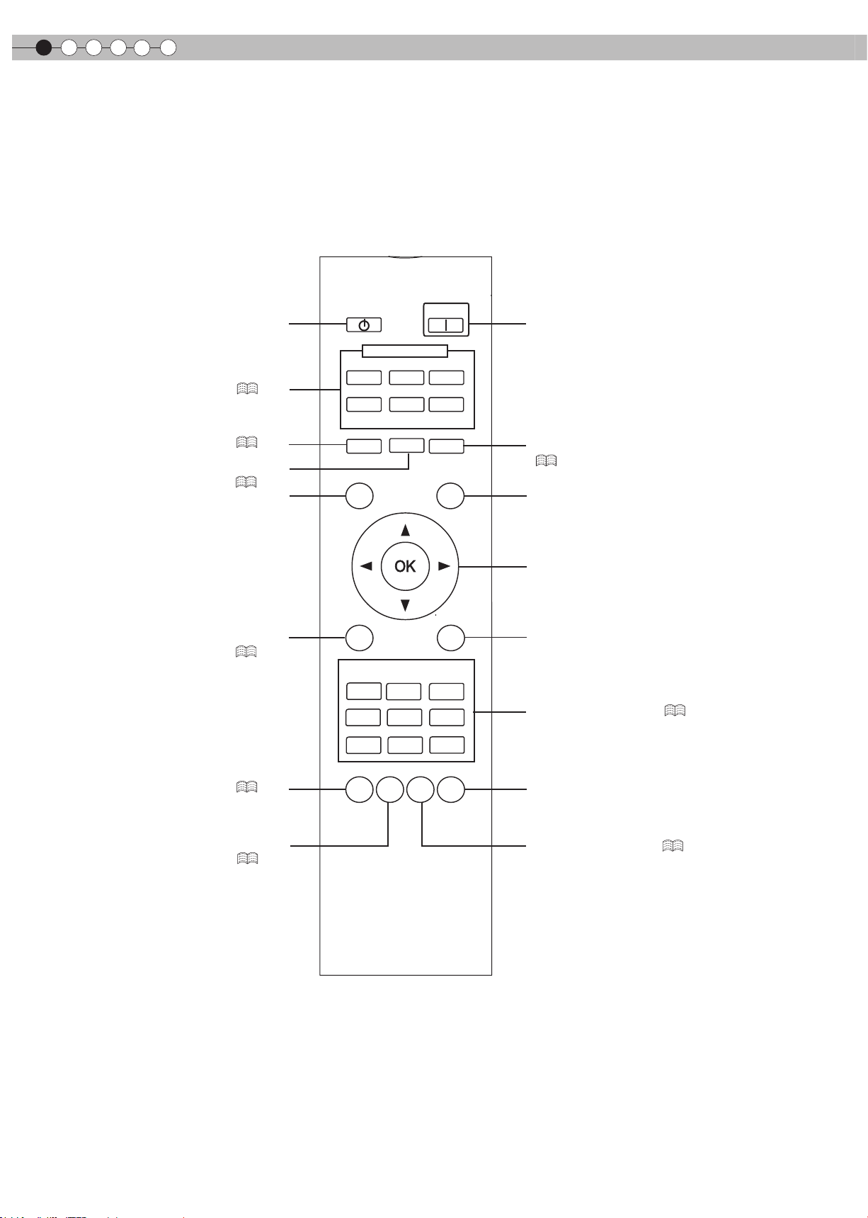
1
Pour commencer
Commandes et fonctionnalités (Suite)
■
Télécommande
Pour éteindre l’appareil
Pour changer d'entrée (
Pour contrôler l'objectif (
Pour régler la taille de l'écran
(
Pour afcher la mire de test
Afcher / Masque le menu
(
P24
P24
P26
P30
STAND BY
ON
Pour allumer l’appareil
INPUT
HDMI 1
HDMI 2
COMP.
)
VIDEO
S-VIDEO
)
LENS
ASPECT
PC
HIDE
Pour masquer temporairement l'image
P25
)
(
)
TEST
LIGHT
Pour allumer les boutons de la télécommande
pour 7 secondes
Pour sélectionner ou conrmer
MENU
BACK
Pour retourner au menu précédent
)
PICTURE MODE
CINEMA
2
STAGE
CINEMA
3
DYNAMIC
Pour changer de mode(
P42
)
CINEMA
1
NATURAL
Pour régler le gamma (
P42
Pour régler la température de couleur
(
P42
USER2
USER1
)
GAMMA
C.TEMP
LENS.
AP.
THX
PIC.
ADJ.
Commute séqu e n t i e l l ement entre
Contraste, luminosité, couleur, teinte,
détail et l’amélioration de détail.
Ouverture de l'objectif (
P42
)
)
14
Page 77

FRANÇAIS
Mise en place des piles
Portée efcace de la télécommande
Comment utiliser la télécommande
Pour commencer
1
2 3
● S’il est nécessaire de rapprocher la télécommande du projecteur pour qu’elle fonctionne, cela signie que les piles sont
faibles. Quand cela survient, remplacer les piles. Insérer les piles selon les marques
.
● Assurez-vous d’insérer le côté en premier.
● Si une erreur survient lors de l’utilisation de la télécommande, retirez les piles et attendez 5 minutes. Remettez en place les
piles et utilisez la télécommande.
■
En dirigeant la télécommande en
direction de l’appareil
● En visant le récepteur de commande à distance
avec la télécommande, s’assurer que le capteur
situé à l’avant ou l’arrière de l’appareil se trouve à
une distance de moins de 7 m.
● Si la télécommande ne fonctionne pas correcte-
ment, rapprochez-vous de l’appareil.
Cet appareil
30°
30°
20°
20°
Préparation
Fonctionnement
Réglages
■
En cas de réexion à partir de l’écran
● S'assurer que la distance totale (A + B) entre
this unit et l'écran (A) et entre la télécommande et
l'écran (B) est de 7 m.
● Dans la mesure où le rendement des signaux réé-
chis depuis la télécommande different selon le type
d’écran utilisé, la distance de fonctionnement peut
diminuer.
Écran
20°
A
20°
B
Télécommande
30°
30°
Télécommande
Cet appareil
Dépannage
Autres
15
Page 78

2
Préparation
Sélectionner les périphériques à raccorder
● Ne pas allumer avant d’avoir ni le raccordement.
● Les procédures de raccordement peuvent varier selon le type de périphérique utilisé. Pour les détails, se reporter au manuel
d’instructions du périphérique à raccorder.
● Ce périphérique est utilisé pour la projection d’image. Connecter un périphérique de sortie audio tel qu’un amplicateur pour
la sortie audio du périphérique connecté.
● Il est possible que les images ne s’afchent pas, suivant les câbles et les périphériques à brancher.
Pour le câble HDMI (vendu séparément), utilisez seulement un câble approuvé HDMI.
● Suivant la dimension du couvercle du connecteur du câble à brancher, il peut être impossible de brancher cet appareil.
Enregistreur BD/DVD
Connexion à une borne HDMI (
Lecteur BD/DVD
)
P18
Connexion à des bornes de vidéo à composantes (
Connexion à une borne RS-232C
(contrôle externe) (
P52
)
P17
)
Pour connecter à une borne PC (
Connexion à une borne vidéo (
16
P20
PC
)
P17
)
Connexion à une borne S-Vidéo (
Pour raccordement via une borne trigger (
)
P17
Magnétoscope et caméscope
P20
)
Page 79

Raccordements
Raccordement via un câble vidéo et un câble S-vidéo
Raccordement via un câble vidéo composantes
FRANÇAIS
Pour commencer
Cet appareil
Cet appareil
Câble vidéo
(vendu séparément)
à une borne d’entrée vidéo
SYNC
à une borne d’entrée S-vidéo
Câble S-Vidéo
(vendu séparément)
Sortie vidéo
Magnétoscope et caméscope
Sortie S-vidéo
Préparation
Fonctionnement
Réglages
SYNC
aux bornes d’entrée vidéo composantes
Câble vidéo composantes
(vendu séparément)
● Choisissez “COMP.” dans le menu conguration à “Y Pb/Cb Pr/Cr”. ( P35 -
12
Lecteur BD/DVD
Dépannage
Sortie vidéo composantes
bornes
C
R/PR
C
B/PB
Y (vert)
(rouge)
(bleu)
Autres
)
17
Page 80
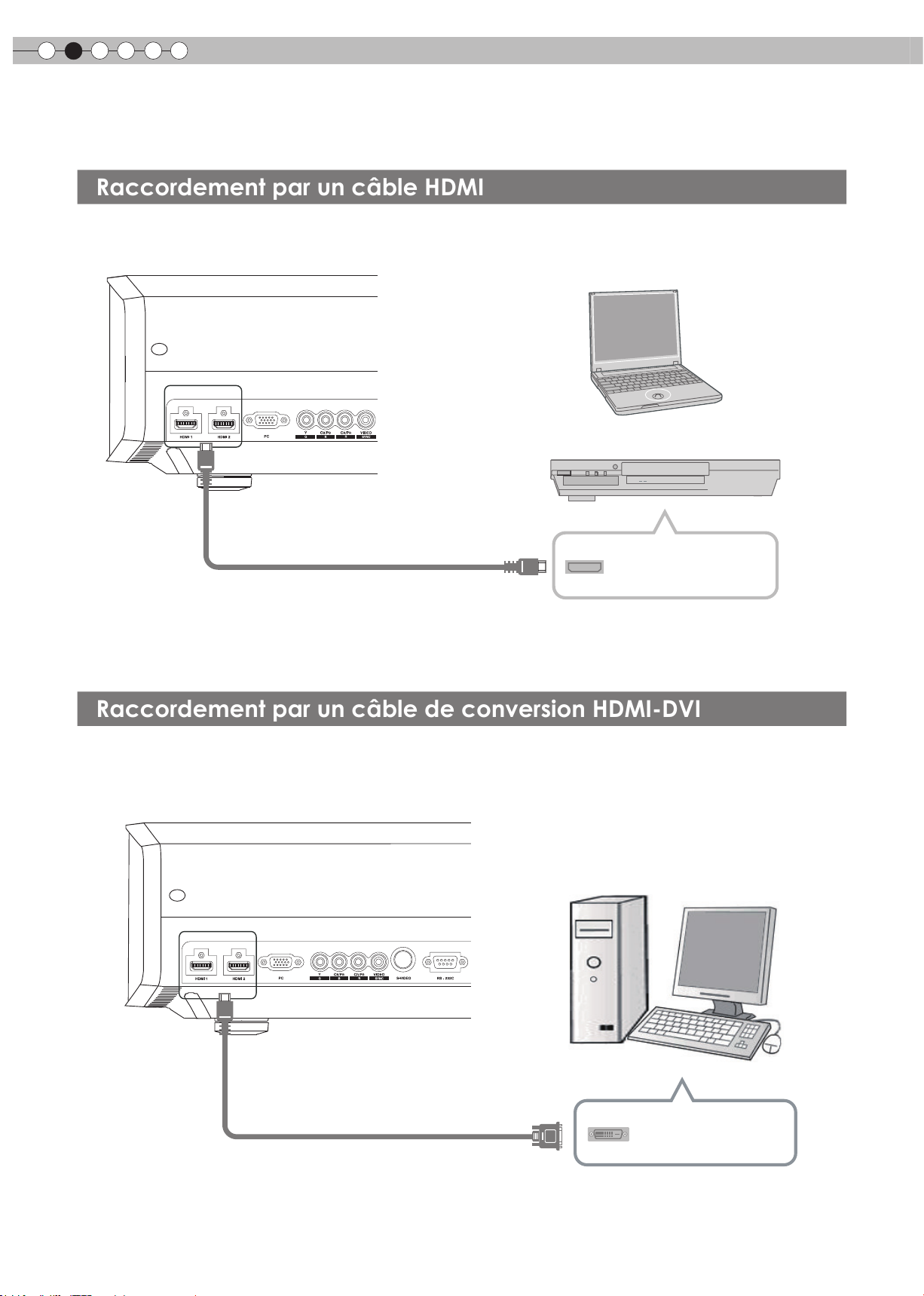
2
Raccordement par un câble de conversion HDMI-DVI
Raccordement par un câble HDMI
Préparation
Raccordements (Suite)
Cet appareil
à une borne d’entrée HDMI 1 ou HDMI 2
Câble HDMI (vendu séparément)
● Si du bruit apparaît, écartez tout PC (PC portable) de ce produit.
● Utiliser seulement un équipement compatible HDMI.
● Il est recommandé de raccourcir la longueur du câble s’il n’y pas d’image.
PC portable
Enregistreur BD/DVD
Borne de sortie HDMI
Cet appareil
à une borne d’entrée HDMI 1 ou HDMI 2
Câble de conversion HDMI-DVI
(vendu séparément)
● Si du bruit apparaît, écartez tout PC (Ordinateur de bureau) de ce produit.
● Il est recommandé de raccourcir la longueur du câble s’il n’y pas d’image.
Ordinateur de bureau
Borne de sortie DVI
18
Page 81
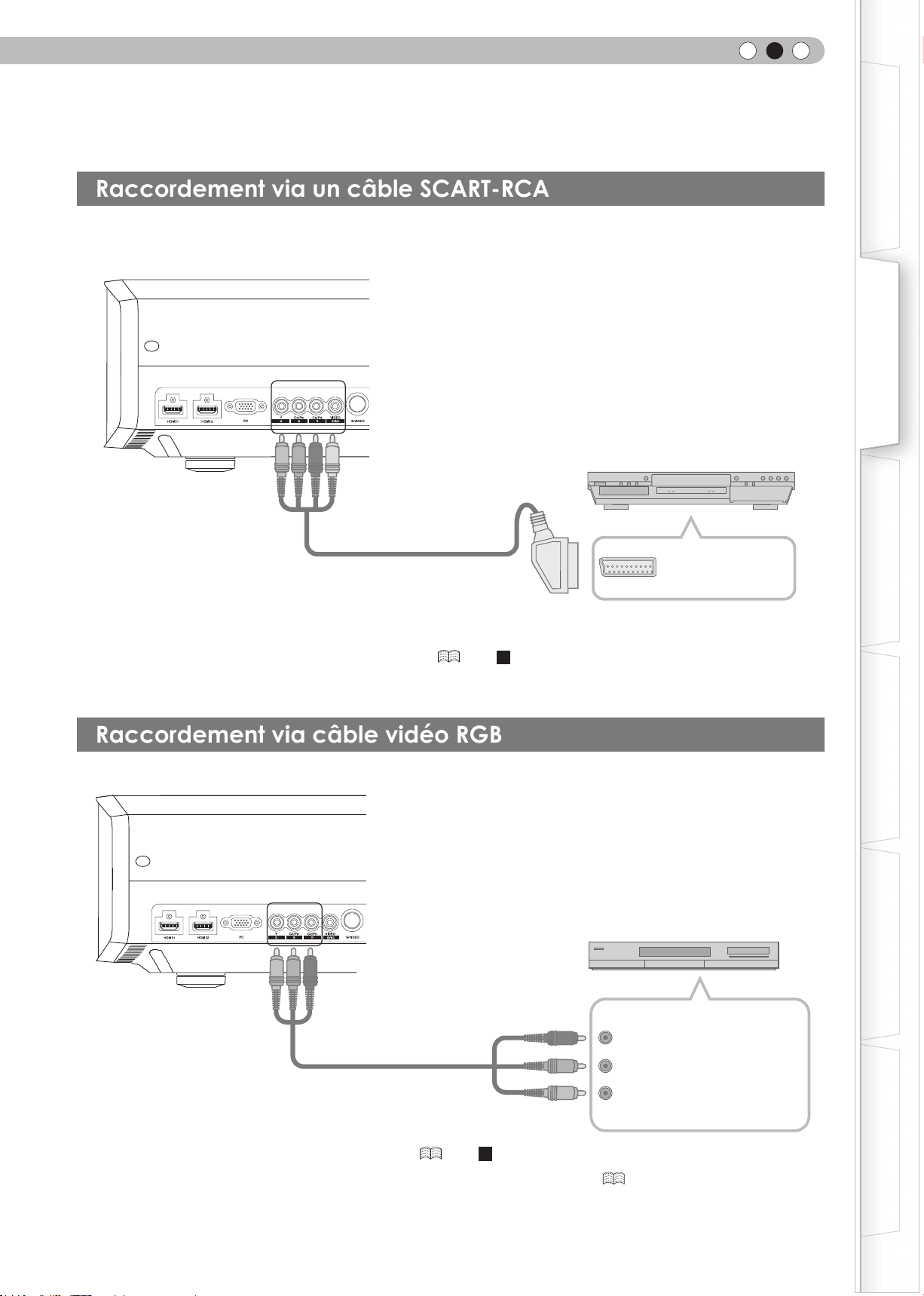
Cet appareil
Raccordement via câble vidéo RGB
Raccordement via un câble SCART-RCA
vers une vidéo RVB et
sync les bornes d'entrée
signal
RS-232C
Câble SCART-RCA
(vendu séparément)
FRANÇAIS
Pour commencer
Préparation
Lecteur BD/DVD pour le marché européen
Fonctionnement
Borne SCART
● Réglez “COMP.” dans le menu conguration à “SCART”. ( P35 -
Cet appareil
RS-232C
à des bornes d’entrée vidéo RVB
câble vidéo RVB
(vendu séparément)
12
)
Réglages
Dépannage
Appareil équipé d'une sortie RVB
Bornes de sortie vidéo RVB
R (Rouge)
B (Bleu)
● Réglez “COMP.” dans le menu conguration à “RVB”. ( P35 -
● Pour plus de renseignements sur les signaux d’entrée, consultez “Caractéristiques”. ( P58)
12
V (vert) :
(Inclut des signaux de synchronisation)
)
Autres
19
Page 82

2
Raccordement par un câble Trigger
Raccordement par
un câble PC
Préparation
Raccordements (Suite)
Cet appareil
PC portable
Vers la borne d'entrée PC
Câble PC (vendu séparément)
Pour plus d’information sur les signaux d’entrée pris en chargé, veuillez consulter les “Caractéristiques”. (
●
Cet appareil
SYNC
Pour commander la borne de sortie
Borne de sortie VGA
Écran
P58
)
N’alimentez pas les autres appareils.
●
Ne connectez pas les câbles audio d'autres appareils tels que
●
Les écouteurs, etc. Sinon, cela peut entraîner un dysfonctionnement
des autres appareils ou des blessures.
Utiliser plus que la valeur indiquée entraînera un dysfonctionnement.
●
Faites très attention à éviter tout court-circuit avec à l’esprit que les
●
sorties des bornes produisent du 12 V.
AVERTISSEMENT
20
Câble Trigger
(Vendu séparément)
Entrée borne Trigger
(Φ3,5)
Page 83

FRANÇAIS
Décalage
Régler l'angle
Installation le projecteur et l’écran
Lors de l'installation, veuillez placer cet appareil et l'écran perpendiculairement l'un par rapport à l'autre.
À défaut, vous risquez d'augmenter la distorsion trapézoïdale. Veuillez vous référer à “Trapèze”. ( P38 -
● L'angle maximal pouvant être donné pour cet appareil est de ±10°.
10°
10°
25
)
Pour commencer
Préparation
10°
10°
● Des dysfonctionnements peuvent survenir si l'angle n'est pas réglé dans la plage de valeurs susmentionnées.
■
Position gauche / droite
* Centrage vertical (0 % de décalage sur l’axe vertical)
Approximativement 34 %
(au maximum) de l’image projetée
Approximativement 34 %
(au maximum) de l’image projetée
■
Position dans l’axe vertical
* Centrage horizontal (0 % de décalage sur l’axe horizontal)
■
Changer la portée de l’image projetée
80%
Fonctionnement
Réglages
Approximativement 80%
Tableau de corrélation de décalage d’objectif:
Décalage gauche-
droite(%)
Décalage haut-
bas(%)
0% 5% 10% 15% 20% 25% 30% 34%
80% 74% 66% 57% 47% 34% 18% 0%
(au maximum) de l’image projetée
Approximativement 80%
(au maximum) de l’image projetée
80%
Centre de
l'objectif.
● Le décalage maximum haut-bas varie avec l’importance du décalage gauche-droite. De même, le décalage
maximum gauche-droite varie avec l’importance du décalage haut-bas.
● Les valeurs du tableau sont conçues comme un guide. Utilisez-les pour référence durant l’installation.
34%34%
Dépannage
Autres
21
Page 84

2
Taille de l’écran et distance de projection
Préparation
Installation le projecteur et l’écran (Suite)
Déterminer la distance entre l’objectif et l’écran pour obtenir la taille d’écran que vous souhaitez.
Cet appareil utilise un objectif avec zoom de facteur x2,0 pour la projection.
■
Taille de l’écran projeté par rapport à la distance de projection
Taille de l'écran de pro-
jection
(Diagonale)
Format d'image 16:9
60"
(Approx. 1,52m)
70"
(Approx. 1,78m)
80"
(Approx. 2,03m)
90"
(Approx. 2,29m)
100"
(Approx. 2,54m)
110"
(Approx. 2,79m)
120"
(Approx. 3,05m)
130"
(Approx. 3,30m)
Distance approximative de projec-
tion W (Wide ou Grand angle) à
T (Téléobjectif)
D'environ 1,78m à
D'environ 2,09m à environ 4,28m
D'environ 2,40m à environ 4,89m
D'environ 2,70m à environ 5,51m
D'environ 3,01m à environ 6,13m
D'environ 3,31m à environ 6,75m
D'environ 3,62m à environ 7,36m
D'environ 3,92m à environ 7,98m
environ 3,66m
Taille de l'écran de pro-
jection
(Diagonale)
Format d'image 16:9
140"
(Approx. 3,56m)
150"
(Approx. 3,81m)
160"
(Approx. 4,06m)
170"
(Approx. 4,32m)
180"
(Approx. 4,57m)
190"
(Approx. 4,83m)
200"
(Approx. 5,08m)
Distance approximative de projec-
tion W (Wide ou Grand angle) à
T (Téléobjectif)
D'environ 4,23m à environ 8,60m
D'environ 4,53m à environ 9,22m
D'environ 4,84m à environ 9,84m
D'environ 5,14m à environ 10,45m
D'environ 5,45m à environ 11,07m
D'environ 5,75m à environ 11,68m
D'environ 6,06m à environ 12,30 m
● Les distances de projection du tableau ci-dessus sont fournies uniquement à titre indicatif. Veuillez en tenir compte lors de
l’installation du projecteur.
● Pour régler l’installation, utiliser une image projetée au format 16:9.
22
Page 85

Mémo
FRANÇAIS
Pour commencer
Préparation
Fonctionnement
Réglages
Dépannage
Autres
23
Page 86

3
BACK
TEST
LIGHT
ASPECT
HIDE
PC
HDMI 1
VIDEO
HDMI 2
S-VIDEO
COMP.
LENS
STAND BY
MENU
CINEMA
3
GAMMA
C.TEMP
USER2
THX
LENS.
AP.
PIC.
ADJ.
PICTURE MODE
INPUT
CINEMA
1
CINEMA
2
NATURAL
STAGE
DYNAMIC
USER1
ON
BACK
Exit
MENU
Zoom
Contrôle Objectif
Retour
Activation
Sélection
Fonctionnement
Projection d'images
Ce chapitre décrit les opérations de base pour projeter des images en entrée sur l’écran.
Préparation
1
Branchez la prise du câble d’alimenta-
tion dans la prise électrique
Raccordez le câble à cet
1
appareil
2
Raccordez à la prise
d’alimentation
1
Cordon d'alimentation
(Fourni)
2
STANDBY/ON
Témoin allumé
(rouge)
WARNING
LAMP
ST ANDBY/ON
2
Allumez l’appareil
ON
STANDBY/ON
Témoin allumé (vert)
● Vous pouvez aussi appuyer sur le bouton sur l'appareil pour
l'allumer. (
P13)
● L’objectif s’ouvrira.
3
Projete l’image
1
Sélectionnez le mode d'entrée
● Vous pouvez également sélectionner le mode d'entrée en appuyant
sur le bouton
HDMI 1 HDMI 2 COMP. Video S-Video PC
2
Afche les images du périphérique sélectionné
4
Règle la mise au point, la taille (zoom) et
sur l'appareil. ( P13)
INPUT
la position (décalage) de l’image.
1
Réglez la mise au point.
Contrôle Objectif
LENS
Ajuster la taille de l'image (le zoom)
2
Mise au point
Exit
MENU
Sélection
Activation
Retour
BACK
Ajustez en conséquence en appuyant
sur les boutons Haut / Bas
24
LENS
Ajustez en conséquence en
appuyant sur les boutons
Haut / Bas
Page 87

Règle la position de l’image (décalage).
3
Contrôle Objectif
LENS
●
Après réglage de la position de l’image, il peut être néces-
saire de sélectionner “Décalage pixels” à partir du menu
Paramètres “Installation”. (
● A chaque pression du bouton
sera de “Mise au point”, “Zoom” and “Décalage”.
LENS
Pour terminer
4
BACK
Décalage
Sélection
Activation
P38 -
Mise au point
Retour
BACK
Ajustez en conséquence en
appuyant sur les boutons
Haut / Bas
)
23
LENS
, l'élément à régler pas-
Zoom
Décalage
FRANÇAIS
CONSEILS
Vous pouvez masquer
temporairement l’image.
Vous pouvez masquer temporairement
l’image.
HIDE
Le témoin vert clignote
lorsque l’image est
masquée
● Appuyez sur le bouton
pour afcher l' image.
HIDE
à nouveau
● L’appareil ne peut pas être éteint lorsque
l’ image est temporairement masquée.
Pour commencer
Préparation
Fonctionnement
Eteingnez l’appareil
5
STAND BY
Lorsqu'’un écran de
confirmation s'affiche
STAND BY
STAND BY/ON
Mode de refroidissement
STAND BY/ON
Clignotement (témoin rouge)
Témoin allumé (rouge)
● Lorsque vous éteignez l’appareil, l’objectif se ferme.
● L'appareil ne peut pas être éteint pendant les 90 secondes
suivant l'allumage de l'appareil. Commez l'utilisation après 90
secondes.
● Vous pouvez aussi appuyer sur le bouton sur l'appareil
pour l'éteindre. (
P13)
● Débranchez le câble d’alimentation lorsque vous n’utilisez pas
l’appareil pour une longue période.
NOTE
À propos du mode de
refroidissement
● Le mode de refroidissement est une
fonction permettant le refroidissement de
la lampe pendant les 60 secondes suivant
la n de la projection. Cette fonction
empêche la déformation ou l’endomma-
gement des pièces internes de l’appareil
du fait de la surchauffe de la lampe. Elle
empêche également un éclatement ou un
raccourcissement prématuré de la durée
de vie de la lampe.
● Pendant la phase de refroidissement, le
témoin [STANDBY/ON] clignote en rouge.
● Suivant la phase de refroidissement,
l’appareil retourne automatiquement en
mode veille.
● Ne débranchez pas la prise d'alimentation
pendant la phase de refroidissement.
Cela pourrait réduire la durée de vie de la
lampe et causer un dysfonctionnement.
Réglages
Dépannage
Autres
25
Page 88

3
Régler de la taille de l’écran
Masquage de la zone périphérique d’une
image
Fonctionnement
Fonctions utiles pendant la projection
Vous pouvez modier la taille de l’écran de l’image projetée ou masquer la zone entourant une image dont
la qualité de la zone périphérique s’est détériorée.
L’image projetée peut être réglée pour correspondre à la taille d’écran
la plus appropriée. (Format d'image).
STAND BY
HDMI 1
VIDEO
LENS
TEST
INPUT
HDMI 2
S-VIDEO
ASPECT
ON
COMP.
PC
HIDE
LIGHT
ASPECT
4:3 16:9 zoom
● La taille de l'écran peut aussi être réglée à partir d'Aspect du menu de con-
guration. (
P36 -
16
)
● Lorsque des signaux PC sont en entrée, le réglage “Aspect(PC)” sera disponible
à la place. (
■
Image source et image projetée par différents paramètres de taille
d’écran
P37 -
Image source
17
)
4:3
Taille de l’écran
16:9
Zoom
MENU
PICTURE MODE
CINEMA
1
NATURAL
USER1
GAMMA
C.TEMP
CINEMA
2
STAGE
USER2
LENS.
AP.
BACK
CINEMA
3
DYNAMIC
THX
PIC.
ADJ.
SDTV (4:3)
Format d’image:
Identique
Taille d’écran la
plus appropriée
Format d’image:
Paysage
L’image est étirée
horizontalement
Format d’image:
Identique
Le haut et le bas
de l’image sont
manquants
SDTV(4:3)
L’image a été
enregistrée au
format paysage
(bandes noires en
haut et en bas)
Format d’image:
Identique
Une petite
image est
projetée
Format d’image:
Paysage
L’image
est étirée
horizontalement
Format d’image:
Identique
Taille d’écran la
plus appropriée
avec le logiciel de
DVD
● Suivant l'image d'entrée, sélectionner 4:3 peut causer un étirement vertical de
l'image, alors que 16:9 vous offre la taille d'écran la plus appropriée.
Les images dont la qualité de la bordure externe est détériorée peuvent être
projetées en masquant (cachant) le pourtour de l’image projetée.
1
Projete l’image
26
Image dont la qualité
de la bordure externe
est détériorée.
Page 89
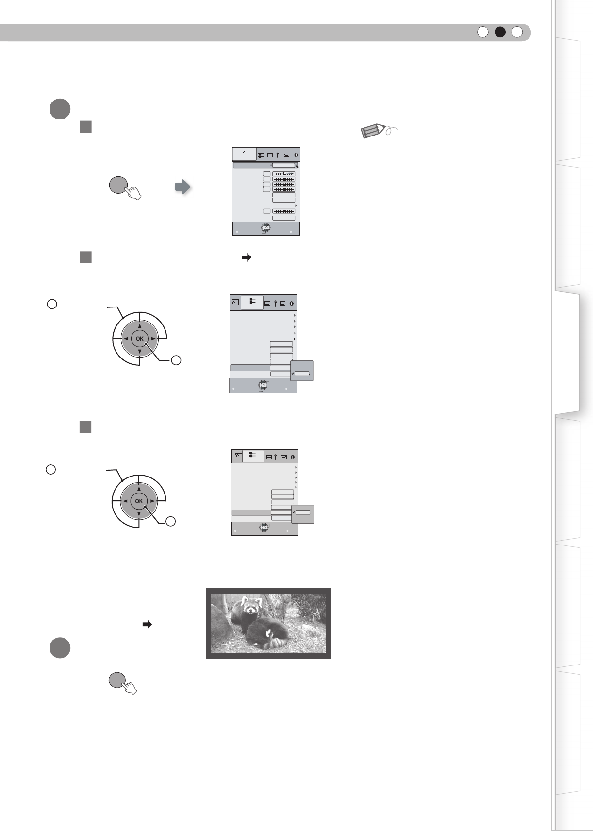
Video/S-Video
COMP.
MENU
BACK
HDMI
Aspect (Vidéo)
Aspect (PC)
Etirement V
16:9
Auto
Arrêt
Surbalayage
Film
Auto
Arrêt
Masque
Arrêt
5%
Arrêt
2.5%
Signal d'entrée
Retour
Activation
Sélection
Sortie
Position image
PC
Masquer l’image
2
1
Afchez le menu de conguration
FRANÇAIS
Pour commencer
NOTE
1
Sélectionner
MENU
2
Choisissez “Signal d'entrée
Confirmer
2
3
Régler une valeur de masque
Qualité image
Modes
Contraste
Luminosité
Couleur
Teinte
Temp. Couleur
Gamma
Avancé
Ouverture
Sortie
MENU BACK
Sélection
Naturel
0
0
0
0
6500K
Normal
0
R.A.Z.
Activation
Retour
” “Masque”
● Le masquage n'est disponible que lorsque
des images haute dénition sont en
entrée.
Préparation
Fonctionnement
1
Sélectionner
Exemple:
Lorsque la valeur “Masque” est
changée de “Off”
Pour terminer
3
MENU
“5%”
2
Confirmer
Signal d'entrée
HDMI
COMP.
Video/S-Video
PC
Position image
Aspect (Vidéo)
Aspect (PC)
Etirement V
Surbalayage
Masque
Film
Sortie
MENU
Sélection
自动
Activation
16:9
Auto
Arrêt
Arrêt
Auto
Réglages
2.5%
5%
5%
Arrêt
Retour
BACK
Dépannage
Autres
27
Page 90

4
Réglages
La structure du menu Paramètres
Le menu pour ce périphérique est structuré de la façon suivante :
AVERTISSEMENT
Certains objets ne peuvent être modiés
●
sans entrée.
Qualité image
01
Modes
02
Contraste
03
Luminosité
04
Couleur
05
Teinte
06
Temp. Couleur.
07
Gamma
08
Avancé
09
Ouverture
10
R.A.Z.
Règle le modèle de l’image projetée.
Paramètre: Cinema 1, Cinema 2, Cinema 3, Naturzl, Scène, Dynamique, Util. 1, Util. 2, THX
Règle le contraste de l’image projetée.
Paramètre: (Noir) -50 à 50 (Blanc)
Règle la luminosité de l’image projetée.
Paramètre: (Plus sombre) –50 à 50 (plus clair)
Règle la densité de la couleur de l’image projetée.
Paramètre: (Plus sombre) –50 à 50 (plus clair)
Règle la teinte de l’image projetée.
Paramètre: (Rouge) –50 à 50 (Vert)
Règle la température de la couleur de l’image projetée.
Paramètre: 5800K, 6500K, 7500K, 9300K, Haute luminosité, Perso 1, Perso 2, Perso 3
Règle les caractéristiques de la gradation de l’image projetée.
Paramètre: Normal, A, B, C, D, Perso 1, Perso 2, Perso 3
Règle les contours de l’image et sa composition détaillée.
Paramètre: Netteté, NR, CTI, R
Réglage de l’ouverture de l’objectif.
Paramètre: –15 à 0
Réinitialiser le réglage.
églage couleur
, Clear Motion Drive
Signal d’entrée
11
HDMI
12
COMP.
13
Vidéo / S-Vidéo
14
PC
15
Position image
16
Aspect (Vidéo)
17
Aspect (PC)
18
Etirement V
19
Surbalayage
20
Masque
21
Film
Congure le signal d’entrée HDMI.
Paramètre: Entrée, Espace color., Contrôle avéc HDMI
Congure le signal d’entrée pour les terminaux d’entrée de la vidéo en composantes.
Paramètre: Y Pb/Cb Pr/Cr, RVB, SCART
Règle les signaux d’entrée Vidéo / S-Vidéo.
Paramètre: Niveau NTSC, Système Couleur
Congure l'entrée PC.
Paramètre: Alignment Auto, Tracking, Phase, Position image
Ajuste la position horizontale / verticale de l’image projetée.
Congure la taille de l’écran de l’image projetée.
Paramètre: 4:3, 16:9, Zoom
Congure la taille de l’écran de l’image projetée.
Paramètre: Auto, 1:1, Plein écran
Lorsque réglé à “Marche”, l’image 2,35:1 projetée sera étirée verticalement à la résolution de
l’écran.
Paramètre: Marche, Arrêt
Choisit s’il faut utiliser le surbalayge ou non pour le signal vidéo SD.
Paramètre: Marche, Arrêt
Masque (cache) la zone externe de l’image projetée.
Paramètre: 2,5%, 5%, Arrêt
Selects this to view movies shot on lm.
Paramètre: Auto, Film, Arrêt
28
Page 91

Installation
22
Contrôle Objectif
23
Décalage pixels
24
Type d’installation
25
Trapèze
26
Type Ecran
FRANÇAIS
Contrôle le déplacement motorisé de l’objectif lors du réglage du projecteur.
Paramètre: Mise au point, Zoom, Décalage, Mire de test, Verrouillage
Effectuez des réglages ns d’un pixel pour chaque décalage de couleur mineur dans le sens ho-
rizontal / vertical de l’image.
Paramètre: Rouge Horiz. , Vert Horiz. , Bleu Horiz. , Rouge Vert. , Vert Vert. , Bleu Vert.
Inverse l’image suivant l’axe vertical (haut ou bas), horizontal (droite ou gauche), suivant l’état de
projection du projecteur.
Paramètre: Proj. Avant, Mont. Plafond AV, Rétro proj. , Mont. Plafond AR
Compense la distorsion trapézoïdale causée par l’installation.
Corrige l’équilibre des blancs biaisé dérivé des caractéristiques réectives de l’écran.
Paramètre: Arrêt, A, B, C
Pour commencer
Préparation
Afchage
27
Couleur fond
28
Position menus
29
Afchage menus
30
Aff. ligne
31
Aff. source
32
Logo
33
Langue
Fonction
34
Puissance lampe
35
Trigger
36
Mire de test
37
Arrêt Auto
38
Haute Altitude
Congure la couleur de l’écran afchée en l’absence de signaux entrants.
Paramètre: Bleu, Noir
Règle la position de l’afchage du menu. Les positions possibles pour l’afchage du menu sont
les quatre coins ou le centre de l’écran.
Dénit la durée de l’afchage du menu.
Paramètre: 15 sec, Marche
Afche ou non le réglage d’entrée lors du changement de source.
Paramètre: 5 sec, Arrêt
Afche ou non l’entrée source lors du changement d’entrée.
Paramètre: Marche, Arrêt
Détermine si “Logo” doit être afché lors du démarrage.
Paramètre: Marche, Arrêt
Détermine la langue d’afchage du menu (12 langues).
Congure la puissance de la lampe source de lumière.
Paramètre: Normal, Haut
Congure la sortie de la borne Trigger.
Paramètre: Arrêt, Marche(Power), Marche(Etir. V.)
Afche 6 types de mires de test.
Eteint automatiquement l’appareil lorsqu’il n’est pas utilisé pendant un certain temps.
Paramètre: 1 heure, 2 heures, 3 heures, 4 heures
Sélectionnez ceci lorsque le projecteur est utilisé dans un endroit à faible pression atmosphé-
rique (supérieure à 900 mètres au dessus du niveau de la mer).
Paramètre: Marche, Arrêt
Fonctionnement
Réglages
Dépannage
Informations
Sont afchés le connecteur d’image, le nom de la source d’entrée, la résolution PC, la fréquence H du PC, la fréquence V
du PC, la profondeur de couleur ainsi que l’utilisation de la lampe.
Autres
29
Page 92

4
Procédures d’utilisation du menu
Réglages
Menu de conguration
Les images projetées peuvent être réglées pour correspondre au format souhaité en changeant les
paramètres par défaut.
Exemple:
Changer l' “Aspect (Vidéo)” de “4:3” à “16:9”
STAND BY
HDMI 1
VIDEO
LENS
TEST
MENU
CINEMA
1
NATURAL
USER1
GAMMA
INPUT
HDMI 2
S-VIDEO
ASPECT
PICTURE MODE
CINEMA
2
STAGE
USER2
LENS.
C.TEMP
AP.
ON
COMP.
PC
HIDE
LIGHT
BACK
CINEMA
3
DYNAMIC
THX
PIC.
ADJ.
Afchez le menu de conguration
1
Qualité image
Modes
Contraste
0
Luminosité
0
0
MENU
2
Choisissez “Signal d'entrée”
Couleur
0
Teinte
Temp. Couleur
Gamma
Avancé
Ouverture
0
Sortie
MENU BACK
Sélection
“Aspect (Vidéo)”
Sélectionner
1
Confirmer
2
Signal d'entrée
HDMI
COMP.
Video/S-Video
PC
Position image
Aspect (Vidéo)
Aspect (PC)
Etirement V
Surbalayage
Masque
Film
Sortie
MENU
Sélection
Naturel
6500K
Normal
R.A.Z.
Activation
4:3
Auto
Arrêt
Arrêt
5%
Auto
Activation
Retour
Retour
4:3
16:9
Zoom
BACK
3
Sélectionner
1
4
30
Régler sur “16:9”
2
Confirmer
Pour terminer
MENU
Signal d'entrée
HDMI
COMP.
Video/S-Video
PC
Position image
Aspect (Vidéo)
Aspect (PC)
Etirement V
Surbalayage
Masque
Film
Sortie
MENU
Sélection
16:9
Auto
Arrêt
Arrêt
5%
Auto
Activation
Retour
BACK
16:9
Zoom
4:3
Page 93

FRANÇAIS
Menu de conguration
Les valeurs des éléments présentés en sont les réglages d'usine prédénis.
● Les éléments pouvant être congurés varient selon les signaux entrants.
AVERTISSEMENT
Certains objets ne peuvent être modiés
●
sans entrée.
Qualité image
01
Modes
Sélectionne le mode Image(Cinéma1, Cinéma2, Cinéma3, Naturel, Scène, Dynamique, Util. 1, Util. 2, et THX).
Cinéma1 Il s’agit du paramètre d’image le plus proche du lm. .Il est adapté au visionnage de lm en général.
Cinéma2
Cinéma3 Il s’agit du paramètre d’image le plus adapté pour visionner des lms d’animation.
Naturel
Scène
Dynamique
THX Il s’agit du paramètre d’image certié par THX Ltd.
02
Contraste
Règle le contraste de l’image projetée.
(Noir) -50 à 50 (Blanc)
03
Luminosité
Règle la luminosité de l’image projetée.
(Plus sombre) –50 à 50 (plus clair)
04
Couleur
Règle la densité de la couleur de l’image projetée.
(Plus sombre) –50 à 50 (plus clair)
05
Teinte
Règle la teinte de l’image projetée.
(Rouge) –50 à 50 (Vert)
Il s’agit du paramètre d’image pour des teintes vives basées sur les normes HDTV. Il est adapté au
visionnage de lms d’action et de lms avec des couleurs vives.
Il s’agit du paramètre d’image pour des teintes et des tons naturels. Il est adapté au visionnage de
drames et de vidéo.
Il s’agit du paramètre d’image le plu adapté pour visionner des concerts en direct et des spectacles
sur scène.
Il s’agit du paramètre d’image le plus adapté pour visionner l’image dans une pièce ne pouvant pas
être rendue totalement sombre.
Pour commencer
Préparation
Fonctionnement
Réglages
Dépannage
Autres
31
Page 94

4
Réglages
Menu de conguration (suite)
Qualité image > Temp. Couleur
06
Temp. Couleur
Règle la température de la couleur de l’image projetée. (Ne peut pas être choisi lorsque les “Modes” sont en “THX”.)
5 800K
6 500K
7 500K
9 300K
Haute luminosité Sélectionnez ceci pour obtenir l’image la plus claire.
Perso 1
Perso 2
Perso 3
Sélectionnez ceci pour donner un ton
rouge à l'image.
Sélectionnez ceci pour avoir une image
balancée.
Sélectionnez ceci pour donner un ton bleu
à l'image.
Choisissez cette option pour donner une
teinte bleue supérieure à 7500K.
Réglage de
Base
Gain (Partie
lumineuse)
Décalage
(Partie som-
bre)
Réglage de
Base
Gain (Partie
lumineuse)
Décalage
(Partie som-
bre)
Réglage de
Base
Gain (Partie
lumineuse)
Décalage
(Partie som-
bre)
Basé sur cette sélection de valeur de correction (5800K, 6500K,
7500K, 9300K, H.B.), règle les gains et décalages suivants.
Rouge (Moins rouge) -50 à 50 (Plus rouge)
Vert (Moins vert) -50 à 50 (Plus vert)
Bleu (Moins bleu) -50 à 50 (Plus bleu)
Rouge (Moins rouge) -50 à 50 (Plus rouge)
Vert (Moins vert) -50 à 50 (Plus vert)
Bleu (Moins bleu) -50 à 50 (Plus bleu)
Seul le décalage peut être réglé.
32
●
Les couleurs rouge, verte et bleur peuvent être respectivement réglées et enregistrées.
●
Ce réglage peut aussi être conguré à partir de la télécommande. ( P14)
Page 95

Qualité image > Gamma
07
Gamma
Règle les caractéristiques de la gradation de l’image projetée.
Normal
A Régle le gamma à sur “A”.
B Régle le gamma à sur “B”.
C Régle le gamma à sur “C”.
D Régle le gamma à sur “D”.
Perso 1
Perso 2
Perso 3
(Réglage gamma)
Dans les cas habituels, choisissez ce
paramétrage.
Trois différents types de gamma peuvent être réglés suivant suivant vos préférences.
Réglage de
Base
Vous pouvez choisir le coefcient (1,8 à 2,6) de la courbe gamma.
Vous pouvez ajuster séparément la courbe gamma des couleurs
Réglage
gamma*
(Rouge, Vert, Bleu).
Régler “Blanc” affectera les valeurs “Rouge, Vert, Bleu”. La courbe
gamma trace les valeurs pour le “Vert”.
Copier Copie la donnée gamma ajustée.
Coller Colle la donnée gamma collée.
R.A.Z.
Remet les coefcients gamma aux valeurs 2,2 réglées dans “Réglage de
Base”.
FRANÇAIS
Il s’agit du paramètres pour des tons standards.
Il s’agit du paramètres pour de riches tons
sombres.
Il s’agit du paramètre pour les qualités de
ton caractéristiques du lm.
Ce paramètre apporte des tons plus riches
et plus sombres que le paramètre B.
Ce paramètre apporte des tons moyens
plus lumineux.
Pour commencer
Préparation
Fonctionnement
● “Normal” convient aux cas habituels, mais d’autres réglages peuvent être sélectionnés selon vos préférences.
● Ce réglage peut aussi être conguré à partir de la télécommande. ( P14)
* “Réglage gamma”
Sélectionne le coefcient de courbe gamma de référence (1,8 ~ 2,6) fznd “Réglage de Base” .
1
Sélectionnez la couleur que vous désirez ajuster dans l’écran d’ajustement gamma.
2
Qualité image
Gamma
Normal
Réglage de Base
1023
A
Blanc
Rouge
B
Vert
C
Bleu
D
Perso 1
Perso 2
Perso 3
Sortie
MENU
Ajustez la courbe gamma dans l’écran d’ajustement courbe gamma.
3
Qualité image
Gamma
Normal
A
B
C
D
Perso 1
Perso 2
Perso 3
Sortie
MENU
Sélectionnez le point où la gradation (luminosité)
sera ajustée au moyen des boutons
Sélection
Sélection
Copier
Coller
R.A.Z.
Activation
Réglage de Base
1023
Blanc
Rouge
Vert
Bleu
Copier
Coller
R.A.Z.
Input: 10%
Output:100
Retour
Activation
512
0
50
100(%)
Contrôle
Retour
Avant
TEST
BACK
Qualité image
Sortie
Gamma
Normal
A
B
C
D
Perso 1
Perso 2
Perso 3
MENU
Sélection
Réglage de Base
1023
Blanc
Rouge
Vert
Bleu
Copier
Coller
R.A.Z.
Input: 50%
Output: 580
Retour
Activation
2.2
512
0
50
100(%)
Contrôle
Retour
Après
TEST
BACK
2.2
512
0
50
100(%)
Contrôle
Retour
Avant
TEST
BACK
Ajustez la gradation (luminosité) au
/ .
moyen des boutons
/ .
● Vous pouvez passer d' “Avant” à “Après” en utilisant le bouton [TEST] de la télécommande.
4
Pour terminer
Réglages
Dépannage
BACKBACK
Voulez vous enregistrer les réglages Gamma ?
Non
Oui
OK
● Si la courbe gamma est ajustée plusieurs fois, des erreurs de calcul seront accumulés et la courbe gamma peut ne pas
être capable de revenir à sa valeur initiale. Dans ce cas, sélectionnez “R.A.Z.”.
Autres
33
Page 96

4
1023
512
50
100(%)
MENU
BACK
0
1.8
Normal
Gamma
Réglage de Base
Blanc
Rouge
Vert
Bleu
Copier
Coller
R.A.Z.
Qualité image
Retour
Retour
Activation
Sélection
Sortie
Input: 50%
Output: 595
A
B
C
D
Perso 1
Perso 2
Perso 3
1023
512
50
100(%)
MENU
BACK
0
2.2
Normal
Gamma
Réglage de Base
Blanc
Rouge
Vert
Bleu
Copier
Coller
R.A.Z.
A
B
C
D
Perso 1
Perso 2
Perso 3
Qualité image
Retour
Activation
Sélection
Sortie
1023
512
50
100(%)
MENU
BACK
0
1.8
Normal
Gamma
Réglage de Base
Blanc
Rouge
Vert
Bleu
Copier
Coller
R.A.Z.
A
B
C
D
Perso 1
Perso 2
Perso 3
Qualité image
Retour
Activation
Sélection
Sortie
Yes
No
Paste gamma data?
Réglages
Menu de conguration (suite)
* Concernant “Copier” et “Coller”.
Copie des données de réglage Gamma.
1
Sélectionner Copier en utilisant les boutons / .
Collage des données copiées.
2
OK
●
Perso 1, Perso 2 et Perso 3.
Qualité image > Avancé
08
Règle les contours de l’image, sa composition détaillée et sa couleur. (Ne peut pas être choisi lorsque les “Modes”
sont en “THX”.)
09
10
Réinitialiser le réglage.
34
Sélectionner Coller en utilisant les boutons
Les données de réglage gamma peuvent être copiées dans tous les modes, mais il est seulement possible de coller dans la
/ et / .
Avancé
Netteté (Doux) de 0 à 100 (Net) Ajuste le contour de l'image
Netteté
NR*
Amélior. Détail (Doux) de –50 à 50 (Fort)
RNR (Doux) de 0 à 16 (Fort)
MNR (Doux) de 0 à 16 (Fort)
Souligne les détails de
l'image
Règle l'intensité de la
réduction du bruit de l'image
Règle l’intensité de la
réduction de l’Effet Gibb.
Marche Réduit le bruit Block Noise
BNR
Arrêt
Le signal d’entrée reste
inchangé.
Arrêt Le signal d’entrée reste inchangé.
CTI*
Bas
Moyen
Haut
Réduit la tache de couleur
(Correction du contour de couleur.).
* Dans le cas de signaux HD ou PC, l'NR et le CTI ne peuvent pas être réglés.
●
Abréviations
NR: Noise Reduction (Réduction du bruit) RNR: Random Noise Reduction (Réduction aléatoire du bruit)
MNR: Mosquito Noise Reduction (Réduction du bruit ‘moustique)
BNR: Block Noise Reduction (Réduction du bruit de bloc)
CTI: Color Transient Improvement (Amélioration des transitoires de couleurs)
églage couleur*
R
Clear Motion Drive*
Arrêt
Perso 1
Perso 2
Perso 3
Arrêt
Bas
Haut
La couleur d'image ne peut pas être ajustée.
Pause
Ajustement
du réglage
couleur*
R.A.Z.
Arrêt
Marche
Les valeurs de chaque couleur peuvent
être réglées (“Rouge, Jaune, Vert, Cyan,
Bleu et Magenta”).
Retourner aux réglages d'usine.
Mode vidéo
Mode image xe
Améliore les images les images à déplacements rapides
en une image claire avec peu d’image résiduelle.
* Avec “Clear Motion Drive”, il n’est pas possible de régler le signal PC. Par ailleurs, selon la scène, l’image peut
être distordue. Dans ce cas, veuillez sélectionner arrêt.
Ouverture
(Sombre) -15 à 0 (Clair)
R.A.Z.
Page 97

* Concernant le “Ajustement du réglage couleur”
7
Teinte
TEST
Contrôle
Après
>
0
0
0
Qualité image
Réglage couleur
Arrêt
Arrêt
Perso 1
Perso 2
Perso 3
Pause
Rouge
Jaune
Vert
Cyan
Bleu
Magenta
R.A.Z.
Teinte
Saturation
Luminosité
Retour
Activation
Sélection
MENU
Sortie
BACK
TEST
Contrôle
Avant
>
0
0
Qualité image
Réglage couleur
Arrêt
Arrêt
Perso 1
Perso 2
Perso 3
Pause
Rouge
Jaune
Vert
Cyan
Bleu
Magenta
R.A.Z.
Saturation
Luminosité
Retour
Activation
Sélection
MENU
Sortie
BACK
TEST
Contrôle
Avant
0
Teinte
1
Choisissez le mode image du réglage couleur.
Choisissez la couleur à régler avec le réglage couleur.
2
4
Sélectionnez “Teinte”, “Saturation” ou “Luminosité” à l'aide du bouton
FRANÇAIS
Pour commencer
3 Choisissez le réglage couleur.
Préparation
/ .
5
Utilisez le boutons
/ pour effectuer le réglage.
● Vous pouvez passer d' “Avant” à “Après” en utilisant le bouton [TEST] de la télécommande.
6
Pour terminer
BACK BACK BACK
Voulez vous enregistrer les réglages de couleur ?
Oui
Non
OK
● Après avoir sélectionné “Cinéma 1”, “Cinéma 2” ou “Cinéma 3” depuis “Mode d’image”, et après un réglage “Avancé”, un
réglage de la luminosité de chaque mode de la “Gestion des couleurs” n’est pas possible.
Signal d'entrée > HDMI
11
HDMI
Congure le signal d'entrée HDMI.
Auto Règle automatiquement les signaux d'entrée.
Entrée
Espace color.
Contrôle avéc HDMI
Standard
Amélioré
Auto Règle automatiquement les signaux d’entrée.
Y Cb Cr (4:4:4)
Y Cb Cr (4:2:2)
RVB
Marche Active les communications CEC.
Arrêt Désactive les communications CEC.
Sélectionnez ceci lorsque la plage dynamique des images
d'entrée est 16 - 235.
Sélectionnez ceci lorsque la plage dynamique des images
d'entrée est 0 - 255.
Sélectionnez ceci lorsque les signaux vidéos YCbCr(4:4:4)
sont en entrée.
Sélectionnez ceci lorsque les signaux vidéos YCbCr(4:2:2)
sont en entrée.
Sélectionnez ceci lorsque les signaux vidéo RVB sont en
entrée.
● Le réglage est disponible uniquement si le terminal HDMI est choisi.
● L’“(Entrée)Auto” ne fonctionne pas correctement pour certains périphériques sources. Dans ce cas, veuillez utiliser le Mode
standard ou le Mode optimisé.
●
Abréviations
CEC: Consumer Electronics Control (Commande des composants électroniques grand public)
Fonctionnement
Réglages
Dépannage
Signal d'entrée > COMP.
12
COMP.
Congure le signal d'entrée pour les terminaux d'entrée de la vidéo en composantes.
Y Pb/Cb Pr/Cr
Espace color.
RVB
SCART
● Le réglage est disponible uniquement si les bornes vidéo à composantes sont choisies.
Sélectionnez ceci lorsque les signaux de composantes
vidéo sont en entrée.
Sélectionnez ceci lorsque les signaux vidéo RVB sont en
entrée.
Sélectionnez ceci lorsque des signaux vidéo RGB et des
signaux de synchronisation sont entrés via l'interface
SCART sur les marchés européens.
Autres
35
Page 98

4
Réglages
Menu de conguration (suite)
Signal d'entrée > Vidéo / S-Vidéo
13
Vidéo / S-Vidéo
Règle les signaux d'entrée Vidéo / S-Vidéo.
Niveau NTSC
Réglez ceci seulement lorsque les signaux NTSC sont en entrée via la borne vidéo ou S-Vidéo.
●
Système Couleur
0IRE Règle la gradation des signaux sans le réglage 7.5 IRE.
7,5IRE Règle la gradation des signaux avec le réglage 7.5 IRE.
Auto Congure le système de couleurs automatiquement.
NTSC Sélectionnez ceci lorsque le système couleur est NTSC.
NTSC4,43
PAL Sélectionnez ceci lorsque le système couleur est PAL.
PAL-M Sélectionnez ceci lorsque le système couleur est PAL-M.
PAL-N Sélectionnez ceci lorsque le système couleur est PAL-N.
SECAM Sélectionnez ceci lorsque le système couleur est SECAM.
Sélectionnez ceci lorsque le système couleur est
NTSC4,43.
● Le réglage n'est disponible que lorsque l'image d'entrée vidéo ou S-vidéo est projetée.
Signal d'entrée > PC
14
PC
Congure l'entrée PC.
Alignment Auto Règle automatiquement l' “Tracking”, “Phase” and “Position image”.
Tracking
Phase
Position image Règle la position d'afchage de l'image.
Règle la taille horizontale et la zone d'afchage de l'image. (Cela peut varier suivant le
signal, mais ne nécessite normalement pas de réglage.)
Règle les images scintillantes et les images oues. (Cela peut varier suivant le signal,
mais ne nécessite pas normalement de réglage.)
● Cela ne peut être réglé que lorsque l'entrée PC est sélectionnée.
Signal d'entrée > Position image
15
Position image
Ajuste la position horizontale / verticale de l'image projetée.
La position de l’image varie suivant les signaux d’entrée. L’image provenant de même signaux peut ne pas être
●
complètement afchée. Règle la position de l’image à l’aide de ce menu pour afcher l’image correctement.
Signal d'entrée > Aspect (Vidéo)
16
Aspect (Vidéo)
Congure la taille de l'écran de l'image projetée.
4:3 Dénit la taille de l'écran à 4:3 pour l'image projetée.
16:9 Dénit la taille de l'écran à 16:9 pour l'image projetée.
Zoom Zoom les images. (ne peut pas être sélectionné dans le cas de signaux HD.)
● Ce réglage peut aussi être conguré à partir de la télécommande. ( P14)
● Les éléments ne peuvent pas être dénis dans le cas de signaux de PC.
36
Page 99
FRANÇAIS
Signal d'entrée > Aspect (PC)
17
Aspect (PC)
Congure la taille de l'écran de l'image projetée.
Auto
1:1
Plein écran Agrandi le signal PC horizontalement / verticalement.
Ce réglage peut aussi être conguré à partir de la télécommande. (
●
Agrandi le signal PC horizontalement et verticalement jusqu’à ce qu’il prenne la
hauteur de l’écran, en afchant le signal dans son format original.
Afche le signal PC correspondant à l’écran avec un rapport 1 point par pixel. L’écran
de PC peut être afché dans sa taille originale.
)
P14
● Ce réglage ne peut pas être déni dans le cas de signaux SD ou HD.
Signal d'entrée > Etirement V (lorsque des signaux HD ou SD sont en entrée)
18
Etirement V
Lorsque réglé à “Marche”, l'image 2,35:1 projetée sera étirée verticalement à la résolution de l'écran.
Marche L'image 2,35:1 projetée sera étirée verticalement à la résolution de l'écran.
Arrêt
Projette l'image 2,35:1 telle quelle.
(Des bandes noires apparaîtront en haut et en bas.)
● Ce réglage ne peut pas être déni dans le cas de signaux PC.
“Arrêt” “Marche”
Pour commencer
Préparation
Fonctionnement
Signal d'entrée > Surbalayage
19
Surbalayage
Choisit s'il faut utiliser le surbalayge ou non pour le signal vidéo SD.
Marche Surbalayage le haut, la gauche, le bas et la droite, chacun à 2,5%.
Arrêt Ne pas surbalayer.
Ce réglage n'est pas disponible lorsque un signal PC ou HD est en entrée.
●
Signal d'entrée > Masque
20
Masque
Masque (cache) la zone externe de l’image projetée.
2,5% Masque 2,5% de l'écran.
5% Masque 5 % de l'écran.
Arrêt Aucun masque.
● Le masquage est disponible uniquement pour des images haute dénition.
Signal d'entrée > Film
21
Film
Sélectionnez ceci pour visionner des lms tournées sur pellicule.
Auto
Film
Arrêt Règle la conversion progressive appropriée pour la vidéo.
Seulement 480i/576i/1080i sont sélectionnables.
●
Sélectionner “Auto” ou “Arrêt” si le fonctionnement devient inadéquat. Ceci ne fonctionne pas correctement en particulier
●
avec la vidéo.
Une fois déterminé s’il s’agit d’un lm à 24 images ou d’une vidéo à 60 images (50
images), change le paramètre pour la conversion progressive optimale.
Corrige le mouvement non naturel du traitement de l’ajustement matériel de 24 à 60
images (50 images) retourné en 24 images.
Réglages
Dépannage
Autres
37
Page 100

4
Réglages
Menu de conguration (suite)
Installation > Contrôle Objectif
22
Contrôle Objectif
Contrôle le déplacement motorisé de l’objectif lors du réglage du projecteur.
Mise au point Fonction pour régler la mise au point de l’objectif.
Zoom Fonction pour régler le zoom de l’objectif.
Décalage
Mire de test
Marche
Fonction pour régler le décalage de l’objectif.
(Appuyez sur les boutons haut / bas / gauche / droite pour faire décaler l’écran).
Afche la mire de test avec les réglages ci-dessus.
Afchage pour
le “Zoom” et
le “Décalage”:
Afchage
pour la
“Mise au
point”:
(Image de grandes grilles vertes)
Arrêt Sans afcher l’image de charge, afche le signal d’entrée externe.
Verrouillage
Marche
Arrêt Permet le réglage de l’objectif.
Désactive le réglage de l’objectif. Un message d’alarme apparaît lorsque le bouton
[LENS] de la télécommande est pressé.
(Image de petites grilles vertes)
Installation > Décalage pixels
23
Décalage pixels
Effectuez des réglages ns d'un pixel pour chaque décalage de couleur mineur dans le sens horizontal / vertical de l'image.
Rouge Horiz. (Déplacer le rouge vers la gauche) 1 à 7 (déplacer le rouge vers la droite)
Vert Horiz. (Déplacer le vert vers la gauche) 1 à 7 (déplacer le vert vers la droite)
Bleu Horiz. (Déplacer le bleu vers la gauche) 1 à 7 (déplacer le bleu vers la droite)
Rouge Vert. (Déplacer le rouge vers le bas) 1 à 5 (déplacer le rouge vers le haut)
Vert Vert. (Déplacer le vert vers le bas) 1 à 5 (déplacer le vert vers le haut)
Bleu Vert. (Déplacer le bleu vers le bas) 1 à 5 (déplacer le bleu vers le haut)
● Les axes horizontaux et verticaux sont inversés lorsque l'image est renversée vers la gauche, la droite, vers le haut ou vers
le bas.
● Lors de l'ajustement, utilisez des images xes avec des contours forts.
● Comme les ajustements sont mineurs, leur effet pourrait être difcile à voir avec certaines images.
Installation > Type d'installation
24
Type d'installation
Inverse l’image suivant l’axe vertical (haut ou bas), horizontal (droite ou gauche), suivant l’état de projection du projecteur.
Proj. Avant Sélectionnez ceci pour une projection avant depuis une table.
Mont. Plafond AV Sélectionnez ceci pour une projection avant depuis le plafond.
Rétro proj. Sélectionnez ceci pour une projection arrière depuis une table.
Mont. Plafond AR Sélectionnez ceci pour une projection arrière depuis le plafond.
Installation > Trapèze
25
Trapèze
Compense la distorsion trapézoïdale causée par l'installation.
● Si le “Réglage du décalage” est autre que 0%, l’image peut être projetée à l’écran de façon incorrecte lorsque la distorsion
trapézoïdale est compensée. (
P21)
38
 Loading...