

Page 1

SERVICE MANUAL
HOME THEATER PROJECTOR
PA01920051
DLA-HD2KU, DLA-HD2KE
¨
ON
OFF
OPERATE
FOCUS
TEST
LIGHT
MENU EXIT
ENTER
PRESET
HIDE
TABLE OF CONTENTS
1 PRECAUTION. . . . . . . . . . . . . . . . . . . . . . . . . . . . . . . . . . . . . . . . . . . . . . . . . . . . . . . . . . . . . . . . . . . . . . . . . 1-3
2 SPECIFIC SERVICE INSTRUCTIONS . . . . . . . . . . . . . . . . . . . . . . . . . . . . . . . . . . . . . . . . . . . . . . . . . . . . . . 1-7
3 DISASSEMBLY . . . . . . . . . . . . . . . . . . . . . . . . . . . . . . . . . . . . . . . . . . . . . . . . . . . . . . . . . . . . . . . . . . . . . . 1-13
4 ADJUSTMENT . . . . . . . . . . . . . . . . . . . . . . . . . . . . . . . . . . . . . . . . . . . . . . . . . . . . . . . . . . . . . . . . . . . . . . . 1-18
5 TROUBLESHOOTING . . . . . . . . . . . . . . . . . . . . . . . . . . . . . . . . . . . . . . . . . . . . . . . . . . . . . . . . . . . . . . . . . 1-29
COPYRIGHT © 2005 Victor Company of Japan, Limited
No.PA019
2005/1
Page 2
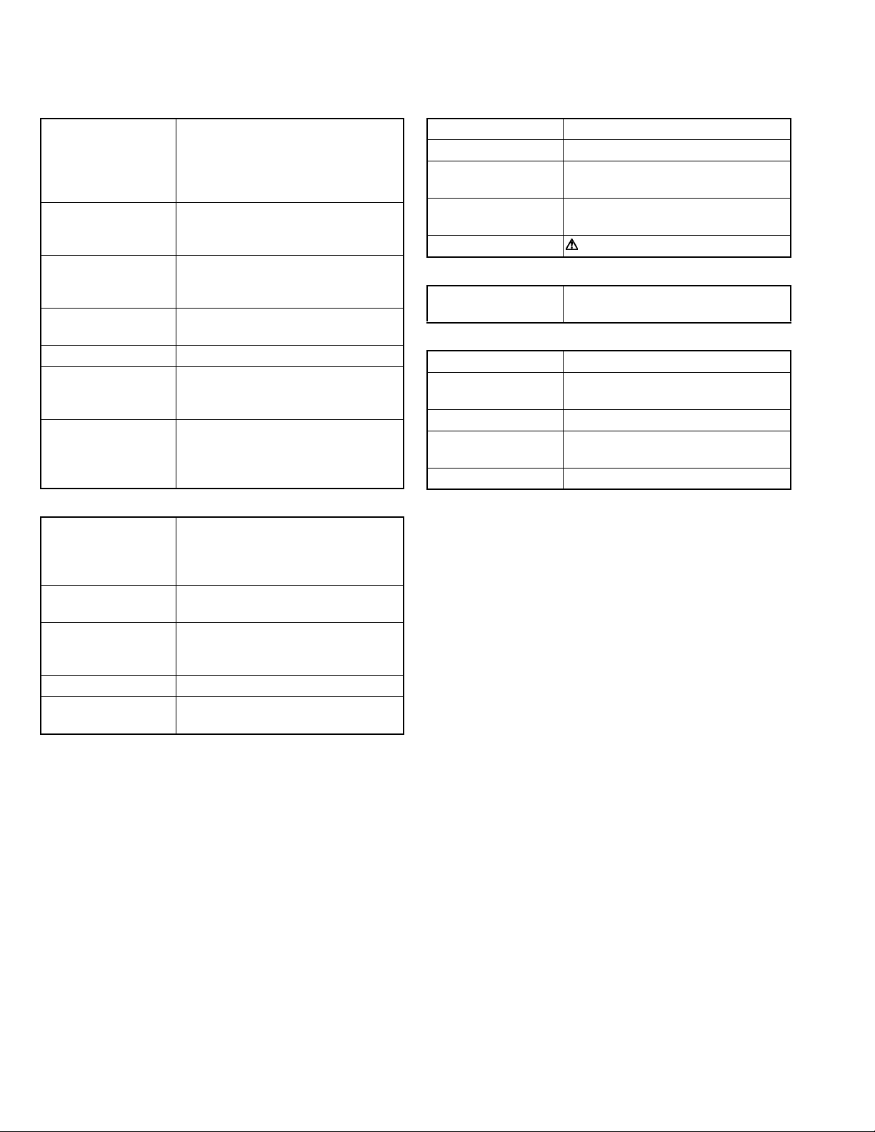
SPECIFICATION
GENERAL
Type
Dimensions
(W × H ×D)
Mass
Power requirements
Power Consumption
Operating temperature
Operating humidity
Storage temperature
Projection angle
(Adjustable Foot)
Remote control unit RM-MH2KG
operation
Accessories Remote control unit (RM-MH2K) × 1
OPTIC
Projection system
D-ILA device
Projection lens 1.3times (1.8 : 1-2.35 : 1) manual ZOOM
Screen size 40" (101.6cm) [tele : min]-200" (508cm)
Projection distance approx 1.5m (4.92ft)-12m(39.36ft)
Light lamp BHL5006-S
D-ILA HOME THEATER PROJECTOR
Approx. 298 mm × 134 mm × 360 mm
(Approx. 11-7/8" × 5-3/10" × 14-1/5")
(Excluding handle, lens and protrusions)
Approx. 6.2kg (Approx.13.7lbs)
AC 100-240V 50Hz/60Hz
3.5A (100VAC)~1.4A (240VAC)
+5°~+35°[41°F~95°F]
20%~80% (no-condensation)
-10°C~+60°C[14°F~140°F]
Vertical : max. +6° upper
Horizontal : max. 3° (±1.5°)
Distance : 7m
Angle: Horizontal =±30° Vertical =±20°
Mass
100g (includes dry cell battery)
Dry cell battery (size : UM-4/AAA/R02) × 2
DVI Cable (5m) × 1
Power code (2.5m) × 1
D-ILA(reflective activematrix principle)system
0.82-inch(2.1cm) measured diagonally
[H:1920 pixels × V:1080 pixels] × 3
< Total : 6,220,000 pixels >
lens [50% fix shift]
< recommended >
*measured diagonally with aspect 16:9
UHP(Ultra High-Pressue mercury) lamp
ELECTRIC
Input signal 1080 / 60p signal, 1080 / 50p signal
Resolution 1920 × 1080 dots
Scanning frequency Horizontal : 56.25kHz,67.43kHz,67.5kHz
Vertical : 50Hz,59.94Hz,60Hz
Keystone distortion
correction
Fuse QMF51D2-6R3-J1(6.3A)
OUTPUT TERMINAL
CONTROL SYNC OUT × 1
INPUT CONNECTORS
VIDEO IN
CONTROL Using external computer control
RS-232C RS-232C protocol
SERVICE stereo mini-jack × 1 (For Service)
Top-bottom tilt:
Horizontal=about 25°, Vertical=about 5°
stereo mini-jack (For Service)
DVI DVI-D (single-24pin) terminal
HDCP-compatible
D-sub 9-pin × 1
1-2 (No.PA019)
Page 3
SECTION 1
r
PRECAUTION
1.1 SAFTY PRECAUTIONS
Prior to shipment from the factory, JVC products are strictly inspected to conform with the recognized product safety and electrical codes of the countries in which they are to be
sold.However,in order to maintain such compliance, it is equally
important to implement the following precautions when a set is
being serviced.
1.1.1 Precautions during Servicing
(1) Locations requiring special caution are denoted by labels
and inscriptions on the cabinet, chassis and certain parts of
the product.When performing service, be sure to read and
comply with these and other cautionary notices appearing
in the operation and service manuals.
(2) Parts identified by the symbol and shaded ( ) parts
are critical for safety.
Replace only with specified part numbers.
NOTE :
Parts in this category also include those specified to
comply with X-ray emission standards for products
using cathode ray tubes and those specified for
compliance with various regulations regarding spurious radiation emission.
(3) Fuse replacement caution notice.
Caution for continued protection against fire hazard.
Replace only with same type and rated fuse(s) as specified.
(4) Use specified internal wiring. Note especially:
• Wires covered with PVC tubing
• Double insulated wires
• High voltage leads
(5) Use specified insulating materials for hazardous live parts.
Note especially:
• Insulation Tape
• PVC tubing
•Spacers
• Insulation sheets for transistors
•Barrier
(6) When replacing AC primary side components (transformers,
power cords, noise blocking capacitors, etc.) wrap ends of
wires securely about the terminals before soldering.
Consequently, when servicing these products, replace the
cathode ray tubes and other parts with only the specified
parts. Under no circumstances attempt to modify these circuits.Unauthorized modification can increase the high voltage value and cause X-ray emission from the cathode ray
tube.
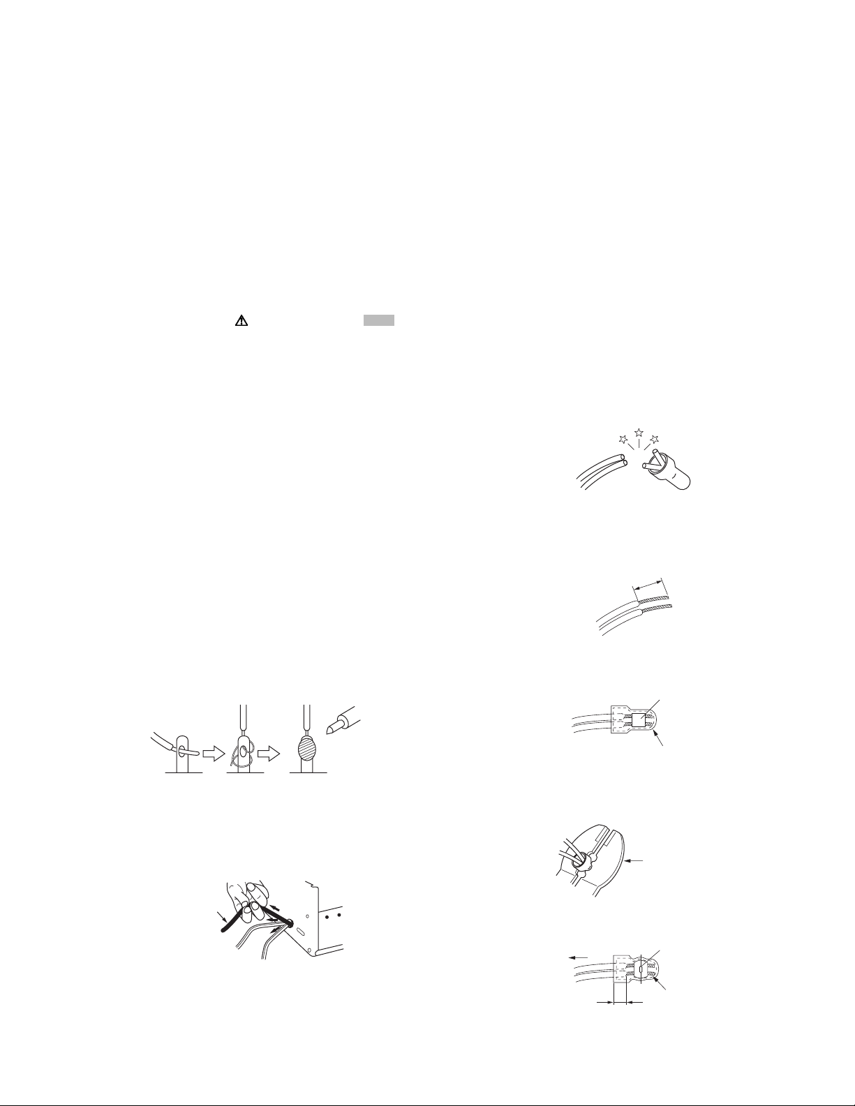
(12) Crimp type wire connectorIn such cases as when replacing
the power transformer in sets where the connections between the power cord and power trans former primary lead
wires are performed using crimp type connectors, if replacing the connectors is unavoidable, in order to prevent safety hazards, perform carefully and precisely according to the
following steps.
• Connector part number :E03830-001
• Required tool : Connector crimping tool of the proper
type which will not damage insulated parts.
• Replacement procedure
a) Remove the old connector by cutting the wires at a
point close to the connector.Important : Do not reuse a connector (discard it).
cut close to connector
Fig.1-1-3
b) Strip about 15 mm of the insulation from the ends
of the wires. If the wires are stranded, twist the
strands to avoid frayed conductors.
15 mm
Fig.1-1-4
c) Align the lengths of the wires to be connected. In-
sert the wires fully into the connector.
Metal sleeve
Fig.1-1-1
(7) Observe that wires do not contact heat producing parts
(heatsinks, oxide metal film resistors, fusible resistors, etc.)
(8) Check that replaced wires do not contact sharp edged or
pointed parts.
(9) When a power cord has been replaced, check that 10-15
kg of force in any direction will not loosen it.
Power cord
Fig.1-1-2
(10) Also check areas surrounding repaired locations.
(11) Products using cathode ray tubes (CRTs)In regard to such
products, the cathode ray tubes themselves, the high voltage circuits, and related circuits are specified for compliance with recognized codes pertaining to X-ray emission.
Connector
Fig.1-1-5
d) As shown in Fig.1-1-6, use the crimping tool to crimp
the metal sleeve at the center position. Be sure to
crimp fully to the complete closure of the tool.
1.2
5
2.0
5.5
Crimping tool
Fig.1-1-6
e) Check the four points noted in Fig.1-1-7.
Not easily pulled free
Wire insulation recessed
more than 4 mm
Crimped at approx. cente
of metal sleeve
Conductors extended
Fig.1-1-7
(No.PA019)1-3
Page 4
1.1.2 Safety Check after Servicing
Examine the area surrounding the repaired location for damage
or deterioration. Observe that screws, parts and wires have been
returned to original positions, Afterwards, perform the following
tests and confirm the specified values in order to verify compliance with safety standards.
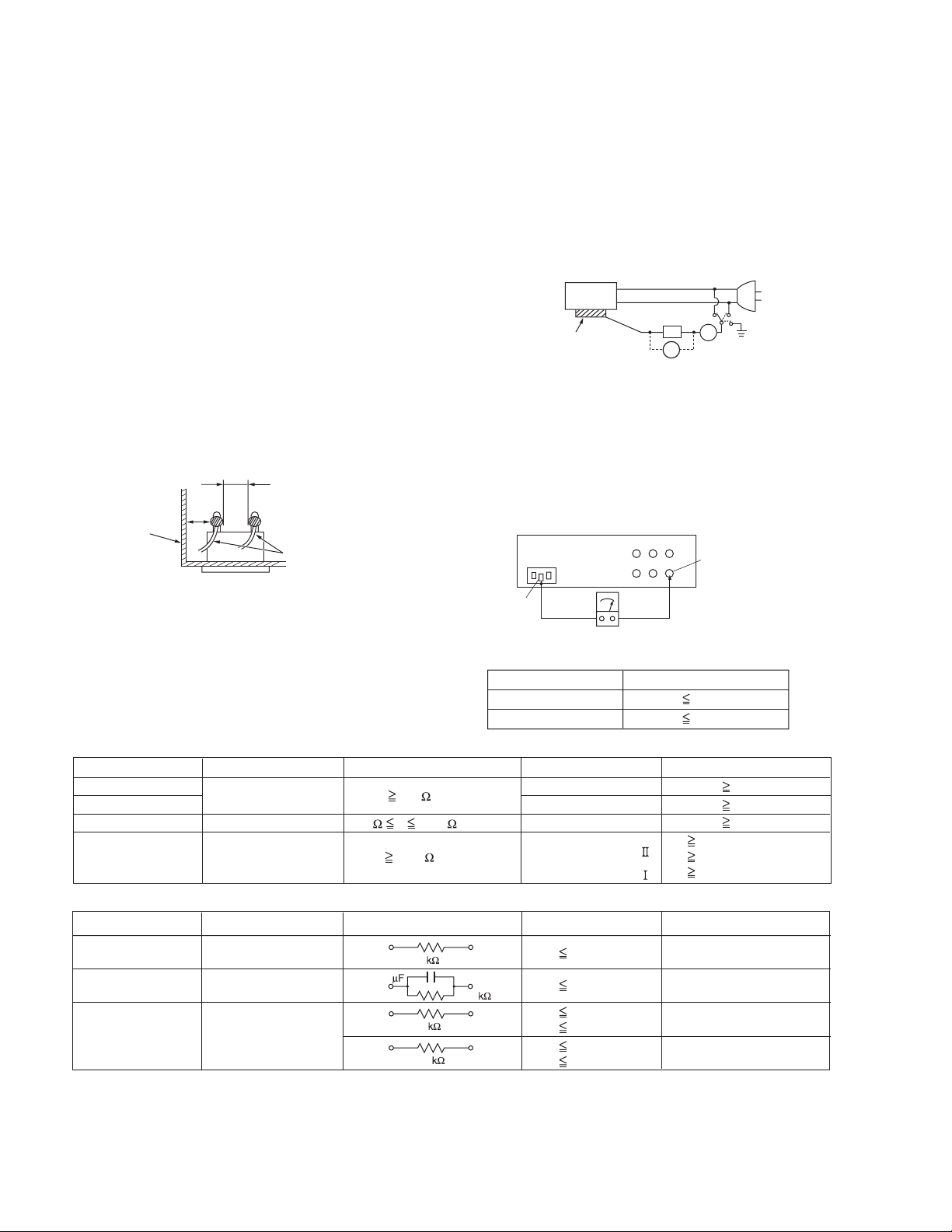
(1) Insulation resistance test
Confirm the specified insulation resistance or greater between power cord plug prongs and externally exposed
parts of the set (RF terminals, antenna terminals, video and
audio input and output terminals, microphone jacks, earphone jacks, etc.).See table 1 below.
(2) Dielectric strength test
Confirm specified dielectric strength or greater between
power cord plug prongs and exposed accessible parts of
the set (RF terminals, antenna terminals, video and audio
input and output terminals, microphone jacks, earphone
jacks, etc.). See Fig.1-1-11 below.
(3) Clearance distance
When replacing primary circuit components, confirm specified clearance distance (d), (d') between soldered terminals, and between terminals and surrounding metallic
parts. See Fig.1-1-11 below.
d
Chassis
d'
Power cord
primary wire
Fig.1-1-8
(4) Leakage current test
Confirm specified or lower leakage current between earth
ground/power cord plug prongs and externally exposed accessible parts (RF terminals, antenna terminals, video and
audio input and output terminals, microphone jacks, earphone jacks, etc.).
Measuring Method : (Power ON)Insert load Z between
earth ground/power cord plug prongs and externally exposed accessible parts. Use an AC voltmeter to measure
across both terminals of load Z. See Fig.1-1-9 and following Fig.1-1-12.
ab
Externally
exposed
accessible part
Z
V
c
A
Fig.1-1-9
(5) Grounding (Class 1 model only)
Confirm specified or lower grounding impedance between
earth pin in AC inlet and externally exposed accessible
parts (Video in, Video out, Audio in, Audio out or Fixing
screw etc.).Measuring Method:
Connect milli ohm meter between earth pin in AC inlet and
exposed accessible parts. See Fig.1-1-10 and grounding
specifications.
AC inlet
Earth pin
Exposed accessible part
MIlli ohm meter
Grounding Specifications
Region
USA & Canada
Europe & Australia
Grounding Impedance (Z
Z 0.1 ohm
Z 0.5 ohm
)
Fig.1-1-10
AC Line Voltage
100 V
100 to 240 V
110 to 130 V
110 to 130 V
200 to 240 V
Region
Japan
USA & Canada
Europe & Australia
Insulation Resistance (R
R 1 M /500 V DC
1 M R 12 M /500 V DC
R 10 M /500 V DC
)
Dielectric Strength
AC 1 kV 1 minute
AC 1.5 kV 1 minute
AC 1 kV 1 minute
AC 3 kV 1 minute
AC 1.5 kV 1 minute
(
Class
(
Class
Clearance Distance (d), (d'
d, d' 3 mm
d, d' 4 mm
d, d' 3.2 mm
d 4 m m
)
d' 8 m m (Power cord
d' 6 m m (Primary wire
)
Fig.1-1-11
AC Line Voltage
100 V
110 to 130 V
110 to 130 V
220 to 240 V
Region
Japan
USA & Canada
Europe & Australia
Load Z
1
0.15
1.5
2
50
Leakage Current (i)
i 1 mA rms
i 0.5 mA rms
i 0.7 mA peak
i 2 mA dc
i 0.7 mA peak
i 2 mA dc
a, b, c
Exposed accessible parts
Exposed accessible parts
Antenna earth terminals
Other terminals
Fig.1-1-12
NOTE :
These tables are unofficial and for reference only. Be sure to confirm the precise values for your particular country and locality.
)
)
)
1-4 (No.PA019)
Page 5
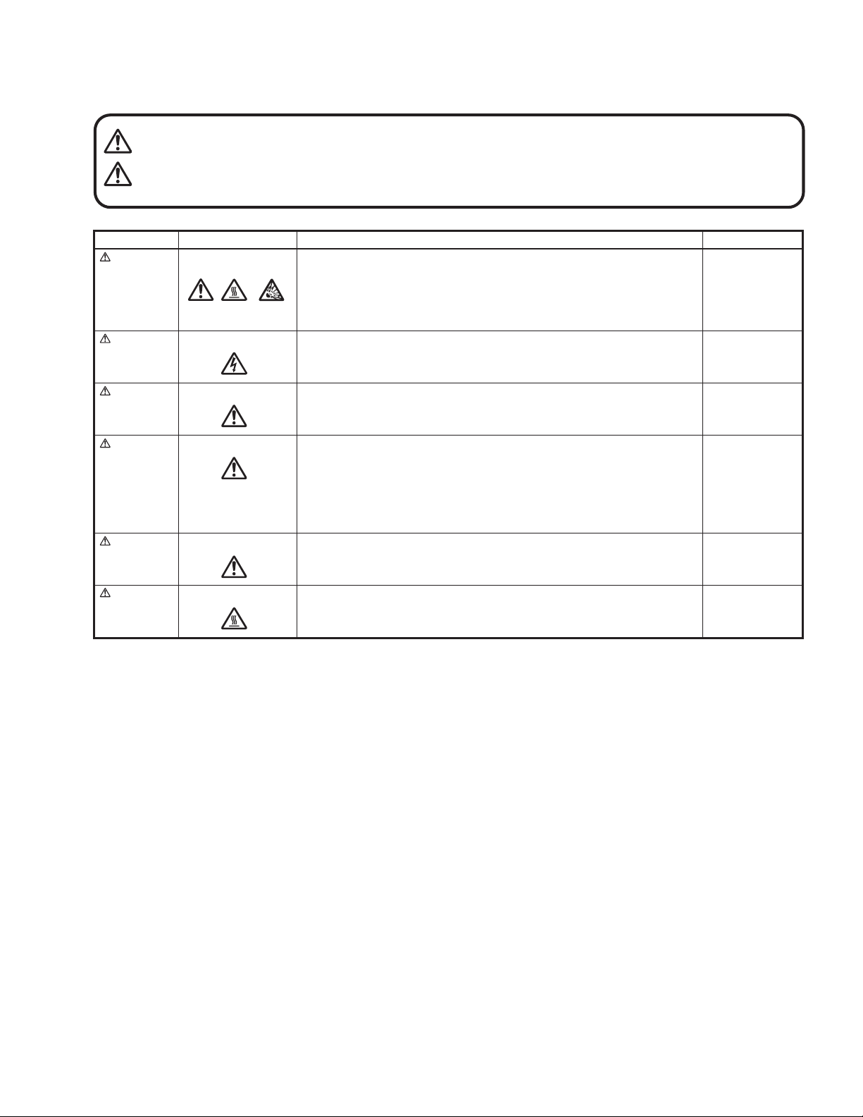
1.1.3 Warning and caution labels
• Labels advising of warning and caution are affixed on and in various locations of the product.
• Take careful notice of these during service and inspection.
WARNING Risk of lethal or otherwise serious personal injury.
CAUTION Risk of personal injury and damage to the product.
Class Pictorial Label advisory Location
WARNING
WARNING
Hot, breakable This projector lamp emits high heat and contains high-pressure during use.
If touched, the lamp (bulb) may rupture and burns may result. Before
attempting to replace the lamp, remove the power cord plug from the outlet and
wait for the lamp (bulb) to cool (at least one hour). Then proceed to replace the
lamp.
High voltage Never open any cover on the projector except the lamp and filter covers.
Dangerous electrical voltage inside the projector.
Bottom chassis
Bottom chassis
WARNING
CAUTION
CAUTION
CAUTION
High brightness Never look into the lens while the projector is on.
There is danger of eye damage.
Hot, shock hazard
High voltage
Hot Caution, high temperature Lamp unit
Do not insert foreign objects into the ventilation holes as this can result in fire or
electrical hazards.
Do not block the ventilation holes as this may cause the internal temperature to
rise and possibly result fire.
When the inside of the unit requires cleaning, consult your nearest JVC dealer
or service center.
Turn off before opening this lamp cover. See user's manual for replacing the
lamp. Replace with the same type (BHL5006-S) lamp rated 250W.
Top cover
Bottom chassis
Bottom chassis
1.1.4 Additional cautionary items
• High voltage is applied for lighting the lamp. During adjustments and other work with the cover removed, extreme care is needed to
avoid electric shock.
• Use care to avoid touching the fan or safety switch terminals during work with the cover removed.
• Select a stable, horizontal work site to prevent dropping the product and components.
• Use the power cord and interface cable supplied with the product.
Before starting work, be sure to also check the safety notices contained in the instruction manual.
(No.PA019)1-5
Page 6

1.2 INSTALLATIONS
1.2.1 Installation method
The D-ILA system (reflecting type active matrix liquid crystal system) does not require convergence adjustment. Note the following
when placed on a floor (refer to OPERATING INSTRUCTIONS for actual operating method).
(1) Place the projector at the position needed for the required image size observe the projector is not tilted horizontally.
[The image size is 40 to 200(wide side) inches diagonal (16:9), requiring a projection distance of 1.58m to 8.03m (wide side).]
(2) Adjust the placement site and screen tilt so that the projection angle is perpendicular to the screen.
(3) Adjust the placement site and screen position (height) so that the projection lens center is at the lower edge of the screen.
(4) Project an image on the screen. (Connect video equipment and power source, switch power on and select the input.)
(5) Fine adjust the projected image position and angle. If adjusting the placement site and screen cannot correct the projected po-
sition (too low) or angle (lower part of image widened), adjust the front foot.
(6) Turn the lens ZOOM ring by hand and adjust for suitable image size.
(7) Turn the lens FOCUS ring by hand and adjust to correct image blur.
1.2.2 Installation site and status
• The projector contains a fan for cooling. Obstruction of the ventilation openings can lead to internal overheating, abnormal operation
and failure. Also observe there is plenty of free space between the projector and adjacent walls, ceiling and other equipment.
Note that excess heat can cause failure and damage to both the projector and nearby equipment.
Required spacing :
Front = 15cm / left and right sides = 30cm / rear = 50cm (When the unit is enclosed with block according to the required spacing
on the left side, provide the unit with adequate ventilation so that the temperature inside of the enclosed area is kept at the same
temperature in the open space in the room.)
• Avoid locations that are wobbly or inclined. If the setting site floor has protrusions or horizontal cannot be maintained, there is risk
the projector may drop, fall over, etc. If located in a site where left to right tilt is greater than ±5° and front to rear tilt greater than
±20°, particularly the optical system components can be severely affected and there is risk basic performance and quality of the
projector cannot be maintained.
• Observe the site can stably bear the weight (approx. 6.2kg) of the projector over a long period of time.
• If mounted on a stand with casters, observe the casters are securely braked to prevent movement.
• Avoid suspending in a location subject to vibration. Both the projector and mounting fixture can be damaged.
• Do not place in the following types of locations.
Especially, Avoid locations subject to dust, grit, smoke or other airborne contaminants. Use adequate caution when providing external ventilation, filters and dust protection.
Near water or in humid sites Near heaters or heat generating equipment
Dust or grit Direct sunlight
Oily or tobacco smokes Very high or very low temperature
1-6 (No.PA019)
Page 7
SPECIFIC SERVICE INSTRUCTIONS
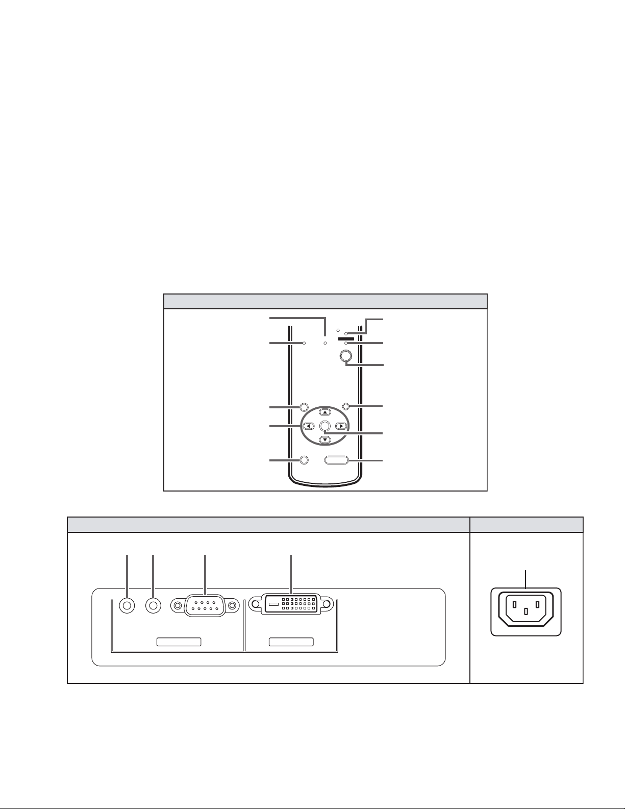
TOP VIEW (Operation Panel)
2.1 FUNCTIONS
2.1.1 LED indications
The LED operations are as follows.
OPERATE LED
Lighted : Power on mode in progress.
Extinguished : Mode other than above.
STAND-BY LED
Lighted : Stand-by mode in progress.
Flashing : Cool down mode in progress.
Extinguished : Mode other than above.
TEMP LED
Flashing : Internal temperature abnormally high
(shift to emergency mode) .
Extinguished : Internal temperature normal.
2.1.2 Operation button & LED location
TOP VIEW (Operation Panel)
TEMP LED
LAMP LED
SECTION 2
LAMP LED
Lighted : Lamp replacement time near (used approx.1900
Flashing : Lamp end of life (approx. 2000 hours), power
Extinguished : Mode other than above
NOTE :
Please refer to troubleshooting about the warning display by
LED.
LAMP TEMP
STAND BY
OPERA TE
hours) At power on, message appears by the onscreen display for advising to "LAMP REPLACE".
on inhibited.
(lamp abnormally absent) .
STAND BY LED
OPERATE LED
MENU BUTTON
CURSOR BUTTON
PRESET BUTTON
2.1.3 Input / output terminal location
SYNC OUT RS-232CSERVICE DVI INPUT
SYNC
OUT
SERVICE
RS-232C
CONTROL
RIGHT SIDE
MENU
PRESET
DVI
VIDEO IN
OPERATE BUTTON
EXIT
ENTER
HIDE
EXIT BUTTON
ENTER BUTTON
HIDE BUTTON
LEFT SIDE
POWER INPUT
(No.PA019)1-7
Page 8
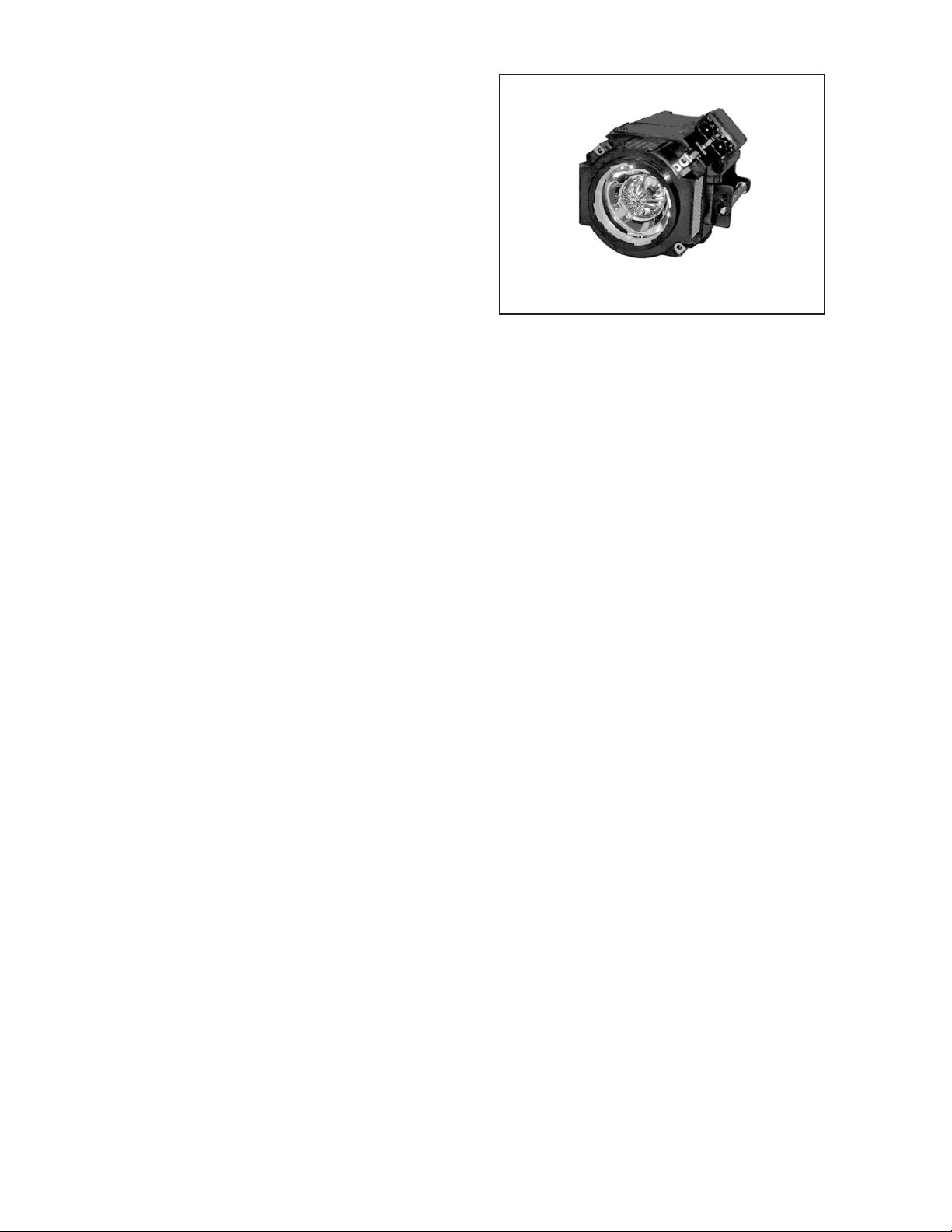
2.2 LAMP UNIT INSTRUCTIONS
Refer to the OPERATING INSTRUCTIONS for a detailed operating description.
2.2.1 Lamp life
Life of the projector lamp (time to reach 1/2 average brightness)
is about 2000 hours.
∗ Lamp use time can be checked at the menu < Information > -
[Lamp time].
LAMP UNIT : BHL5006-S
2.2.2 Operation when lamp use time exceeds 1900 hours
z 1900 to 2000 HOURS
• Power on : LAMP LED lights.
• Operation : "Lamp replacement" message appears on
screen (∗press any button to extinguish).
z 2000 to 2010 HOURS
• Power on : LAMP LED flashes.
• Operation : "Warning" and "Lamp replacement" messages
appear on screen, and "Warning" flashes.
∗Press [EXIT] button to extinguish the display. But after 1
hour, "Warning" and "Lamp replacement" again appear.
NOTE:
At power off, the stand-by mode is produced and further operation is prevented.
∗To again use the projector, replace the lamp unit and reset
the lamp use time indication.
z AFTER 2010 HOURS
• Power on : Power is cut and cool-down mode entered,
LAMP and OPERATE LEDs flash.
2.2.3 Handling cautions
• Use a cross-head screwdriver to take out and reinstall the lamp
cover (2 screws) and lamp unit (2 screws). Refer to the OPERATING INSTRUCTIONS.
• Observe the following cautions.
- Be sure to disconnect the power cord from the AC power
source.
- The lamp remains quite hot after power off. Be sure to allow
plenty of time (30 minutes to 1 hour) to cool before proceeding.
- The lamp can break if dropped or subjected to physical
shock.
- Use care not to directly touch or soil the lamp projecting
(glass) face.
• When installing the lamp unit, observe the interior projections
of the lamp cover are securely inserted into the holes of the
projector. Since the lamp cover projections engage the interlock switch part of the protector circuit (normal operating state),
be sure the cover is properly positioned and secure with
screws.
• The replaced old lamp (depleted lamp unit) can be discarded
in the same manner as a fluorescent lamp. Check local ordinances and dispose of the used lamp as prescribed.
2.2.4 Lamp use time reset
• Be sure to reset the Lamp use time after replacing the lamp
unit. Unless reset, the projector will cease operation (lamp will
not light) when 2000 hours are reached.
∗Conversely, reset the use time only after replacing the lamp.
• RESETTING
(1) Set for stand-by mode.
(2) In sequence, press the [EXIT], [HIDE] and [PRESET]
buttons.
(3) Press the [] button for more than 2 seconds.
∗The STAND-BY and OPERATE LEDs alternately flash
for about 3 seconds, then only the STAND-BY LED
lights steadily.
• RESET AFTER REPLACING MAIN PWB ASS'Y
The lamp use time data are stored in memory on the MAIN
PWB ASS'Y and need to be reentered after replacing the
MAIN PWB ASS'Y. Use the special software and a personal
computer to reenter the data. Afterwards, confirm the mode
has been returned to that prior to board replacement.
1-8 (No.PA019)
Page 9
2.3 PROJECTION SPECIFICATIONS AND NOTES
2.3.1 Projection distance
• The usable projection distance (focus obtainable) is tele side :
approx. 2.07m to 10.45m / wide side : approx. 1.58m to 8.03m.
The picture size (16:9) is 40 to 200 inches.
• Use the wide side for sizes bigger than 200 inches.
• If picture edge distortion occurs at the minimum distance
(1.6m), increase the distance slightly.
• The guaranteed projection distance range is from 2m to 10m.
2.3.2 Projection image and image size
• The projection distances and image size relationship given in
the operation manual is approximate for general reference.
The actual values may vary due to lens tolerance and other
factors.
2.5 SERVICE POLICY
The following service policy is being utilized.
Item Parts number Service method
MAIN PWB ASS'Y LCA90233-01B Replace PWB (Some parts are excluded)
DD SUB1 PWB ASS'Y LCA90234-01B Replace PWB (Some parts are excluded)
DD SUB2 PWB ASS'Y LCA90235-01B Replace PWB (Some parts are excluded)
POWER PWB ASS'Y LCA10383-01A Replace parts
IR1 PWB ASS'Y LCA90271-01B Replace parts
IR2 PWB ASS'Y LCA90236-01B Replace parts
CONT. & 3.3V PWB ASS'Y SXG-0P002A Replace parts
OPERATION PWB ASS'Y LCA90272-01B Replace parts
OPTICAL BLOCK ASS'Y HD2KOP-S Replace (module)
LAMP BALLAST UNIT QAL0435-002 Replace (module)
LAMP UNIT BHL5006-S Replace (module)
2.3.3 Other cautions
• Use care not to directly touch the lens. Clear soiling from the
lens with optical lens paper or a photographer's blower.
• Check the lens cap is removed before projecting. If left installed the projector can overheat and the lens cap can be deformed.
• Sunlight or other illumination can render the image difficult to
see. Use a curtain or other means to shield the screen from
stray light.
2.4 CONNECTION AND OPERATION CAUTIONS
• The projector can function with fH 56.25kHz, 67.43kHz,
67.5kHz, fV 50Hz, 59.94Hz, 60Hz signal input, but even within
this range, partial picture loss, fold-over at the top and bottom
picture edges and other effects can occur according to signal
type and conditions to prevent a normal projected image (see
"Input Sync Frequency" of the OPERATING INSTRUCTION).
2.6 MAIN DIFFERENCE LIST
Part name DLA-HD2KU DLA-HD2KE Remark
PACKING CASE LC21468-005A LC21468-008A
POLY BAG QPA01503005 -------- For Warranty card
WARRANTY CARD BT-51030-3 -------- Accessory
POWER CORD QMPE240-250-R
QMPL280-200-R (for EU)
QMPP220-200-R (for UK)
Accessory
(No.PA019)1-9
Page 10
2.7 SERVICE MENU
options
software version
software version
options
The service menu contains items not ordinarily needed by the user. Use these as necessary during service.
2.7.1 Enter
(1) No menu shown.
(2) Press the [] button.
(3) Within press the [] button.
(4) Within press the [] button.
(5) Within press the [] button.
(6) Within press the [ENTER] button to display the service
menu.
NOTE:
When the Service Menu Screen is not displayed, go back to
the beginning. It is recommended that you press the buttons a
little earlier and steadily.
2.7.2 Release
Press the [MENU] button to exit the menu indication.
2.7.3 Basic operation
Use the following buttons to operate the service menu.
(1) Choose the SETTING MENU with the [/] button.
(2) When the [] button is pressed after choosing the SET-
TING MENU, the cursor will shift to the SETTING / ADJUSTMENT ITEMS of each SETTING MENU.
(3) When the cursor is shifted, choose the SETTING / AD-
JUSTMENT ITEMS with the [/] button.
(4) Using the [/] button, change the setup values and ad-
justment values, respectively.
(5) When the [EXIT] button is pressed, the cursor will return to
the SETTING MENU.
(6) When the [MENU] button is pressed, the SERVICE MENU
will go out of the screen.
NOTE:
The SERVICE MENU will go out of the screen automatically
after 10 seconds if you do not press the [MENU] button.
SERVICE MENU
SETTING NENU SETTING / ADJUSTMENT ITEM
software version
࠰ࡈ࠰ࡈ࠻ࡃ࠻ࡃ࡚ࠫࠫࡦ
options
software version
options
PRG : 014
OSD : 011
DLA-HD2K
Software version SCREEN
Back Color Black
Auto shut off Off
Color temp.
RED
GREEN
BLUE
Factory reset
Adjust pattern
Option SCREEN
Blue
On
USER1 D65 USER2
0
0
0
ENTER
ENTER
1-10 (No.PA019)
Page 11

2.7.4 Setting items
software version
options
Item Initial value
Adjustment
range
Description
Setting
object
Software version
Software version ------ ------ Information of PROGRAM ------
Option
Back color Blue [Select 2 items] "Sets no signal background color to blue or black.
Common
[Blue] : Blue color [Black] :Black color"
Auto shutdown ON [Select 2 items] If POWER OFF is selected, no warning will be displayed on and
Common
after 1900 hours of the lamp operating time. However, POWER
ON is also available after 2000 hours of the lamp operating time.
Color temp D65 Select 3 items Setting of [D65]:6500K, USER1, USER2 Common
R 0 -255~0 Setting color temp of red Common
G 0 -255~0 Setting color temp of green Common
B 0 -255~0 Setting color temp of blue Common
Factory reset ------ ------ Press [ENTER] then all reset. Common
Adjust pattern ------ [Select 3 items] Press [ENTER] then Test pattern appear. (Refer to following Fig.1) Common
Test pattern Screen
convergence
software version
options
SERVICE MENU Screen
Back Color Black
Auto shut off Off
Color temp.
RED
GREEN
BLUE
Factory reset
Adjust pattern
Blue
On
USER1 D65 USER2
0
0
0
ENTER
ENTER
checkercross-hatch
(When the key is pressed, the screen is changed one after the other as shown in the above.)
(No.PA019)1-11
Page 12

2.8 FACTORY SHIPPING SETTING
SET (PROJECTOR) / REMOTE CONTROL UNIT
Switch / Item
MAIN POWER
VIDEO
HIDE
MENU
Item
Image adjust
Gamma
Color temp.
Color temp.
RED
GREEN
BLUE
Test pattern
Set up
Menu Position
Mask
Source
Position
OFF
VIDEO
OFF (display)
Position
2.2
ENTER
D65
0
This adjustment is only
available when the USER is
0
selected for color temperature.
0
ENTER
CENTER
Off
60p
Item Position
Options
Menu display
Flip H
Flip V
Picture Shift
Sleep time
RS232C (bps)
15sec
Off
Off
0
Off
19200
Information
Lamp time < Lamp usage time >
1-12 (No.PA019)
Page 13

SECTION 3
DISASSEMBLY
Notes:
• Confirm that the power cord is unplugged from the AC outlet before proceeding.
• The lamp remains quite hot after turning the power off. Allow sufficient time to cool before starting work.
3.1 LENS COVER
(1) Rotate the LENS COVER on the front of the main frame
counterclockwise and release the lock. Then pull out the
LENS COVER toward you. (Fig.1)
3.2 LAMP UNIT COVER
(1) Loosen the 2 screws marked A on the right side of the main
frame and pull out the LAMP UNIT COVER toward you.
(Fig.2)
These 2 screws are not removed from the LAMP UNIT
COVER.
3.3 TOP COVER
• Remove the LENS COVER.
• Remove the LAMP UNIT COVER.
(1) Remove the 1 screw marked B and the 2 screws marked C
on the right side of the main frame. (Fig.2)
(2) Remove the 3 screws marked D on the left side of the main
frame. (Fig.2)
(3) Remove the 1 screw marked E on the rear side of the main
frame. (Fig.2)
(4) Remove the harness from the connector CN701
CONTROL UNIT which is secured to the back of the TOP
COVER.
(5) Lift up the TOP COVER to remove it.
3.4 PROTECT COVER
• Remove the LENS COVER.
• Remove the LAMP UNIT COVER.
• Remove the TOP COVER.
(1) Remove the 1 screw marked E' fixing the PROTECT COV-
ER, and lift up the PROTECT COVER to remove it. (Fig.2)
3.5 CONTROL UNIT
• Remove the LENS COVER.
• Remove the LAMP UNIT COVER.
• Remove the TOP COVER.
(1) Remove the 5 screws marked F fixing the CONTROL UNIT
from the back of the TOP COVER. (Fig.2)
(2) Remove the CONTROL UNIT. (Fig.2)
of the
LENS COVER
Fig. 1
D
(x3)
(x1)
CN710
TOP COVER
E'
F
(x5)
CONTROL UNIT
C
(x1)
E
(x1)
A
(x2)
LAMP UNIT COVER
BOTTOM CHASSIS
Fig.2
C
(x2)
B
(x1)
(No.PA019)1-13
Page 14

3.6 TERMINAL PWB ASS'Y AND MAIN PWB ASS'Y
• Remove the LENS COVER.
• Remove the LAMP UNIT COVER.
• Remove the TOP COVER.
(1) Remove the 6 screws marked J fixing the MAIN PWB
ASS'Y. (Fig.3)
(2) Remove the harness from the connectors CN710
.
CN711
(3) Remove the cord wire from the connector CN504 and
.
CN505
(4) Remove the harness from the connectors CN501
, CN502,
CN503, CN714, CN707, CN706, CN705, CN713, CN704
and CN708.
3.7 TERMINAL BOARD AND SHIELD SHEET
• Remove the LENS COVER.
• Remove the LAMP UNIT COVER.
• Remove the TOP COVER.
• Remove the MAIN PWB ASS'Y. *1
and
(1) Remove the 4 screws marked G fixing the TERMINAL
BOARD. (Fig.3)
(2) Remove the TERMINAL BOARD.
(3) Using a nut driver and the like, remove the 4 screws
marked H fixing the D-SUB connector and DVI connector.
(Fig.3)
(4) Pull out the SHIELD SHEET toward you to remove it.
*1
After (2) in the procedure above, the TERMINAL BOARD and
the SHIELD SHEET can be replaced. However, be careful
about the cord wire and the harness that are not replaced.
3.8 MAIN PWB ASS'Y
• Remove the LENS COVER.
• Remove the LAMP UNIT.
• Remove the TOP COVER.
• Remove the MAIN PWB ASS'Y.
• Remove the TERMINAL BOARD and the SHIELD SHEET.
(1) Remove the 1 screw market K and the 6 screws marked J
fixing the MAIN PWB ASS'Y.
CN714
CN707
CN706
CN705
CN713
CN704
CN708
CN701
CN505
CN503
CN504
K
CN502
CN501
(x1)
CN711
CN710
J
(x6)
MAIN PWB ASS'Y
SHIELD SHEET
H
(x4)
TERMINAL BOARD
G
(x4)
1-14 (No.PA019)
Fig.3
Page 15

3.9 LAMP UNIT UPPER BRACKET
• Remove the LENS COVER.
• Remove the LAMP UNIT.
• Remove the TOP COVER.
• Remove the MAIN PWB ASS'Y.
(1) Remove the 2 screws marked M fixing the LAMP UNIT UP-
PER BRACKET. (Fig.4)
(2) Pull out the LAMP UNIT UPPER BRACKET in the direction
of the arrow.
3. 10 POWER SUPPLY SHIELD CASE(1) and LAMP BALLAST UNIT
• Remove the LENS COVER.
• Remove the LAMP UNIT.
• Remove the TOP COVER.
• Remove the MAIN PWB ASS'Y.
• Remove the LAMP UNIT UPPER BRACKET.
(1) Remove the 5 screws marked N fixing the POWER SUP-
PLY SHIELD CASE(1). (Fig.4)
(2) Disconnect the connectors CN1
and CN2.
(3) Remove the 1 screw marked O fixing the LAMP POWER
SUPPLY CORD SUPPRESSION BRACKET. (Fig.4)
(4) Lift up the LAMP POWER SUPPLY CORD SUPPRES-
SION BRACKET to remove it, and remove the LAMP
POWER SUPPLY CORD.
(5) After setting up the POWER SUPPLY SHIELD CASE(1),
remove the 4 claws marked a which secure the LAMP BALLAST UNIT to the back of the POWER SUPPLY SHIELD
CASE. (Fig.4)
N
(x5)
LAMP BALLAST UNIT
POWER SUPPLY SHIELD CASE(1)
CN2
CN1
M
(x2)
a
LAMP UNIT UPPER BRACKET
O
(x1)
LAMP POWER SUPPLY CORD
SUPPRESSION BRACKET
LAMP POWER SUPPLY CORD
Fig.4
(No.PA019)1-15
Page 16

3.11 POWER SUPPLY PWB ASS'Y
• Remove the LENS COVER.
• Remove the LAMP UNIT.
• Remove the TOP COVER.
• Remove the MAIN PWB ASS'Y.
• Remove the LAMP UNIT UPPER BRACKET.
• Remove the POWER SUPPLY SHIELD CASE(1).
(1) Remove the 4 screws marked P fixing the POWER SUP-
PLY PWB ASS'Y. (Fig.5)
(2) Disconnect the POWER SUPPLY CORD from the connec-
tor CN001
.
(3) Pull out the harness from the THERMOSTAT PROTEC-
TOR.
(4) Pull out the POWER SUPPLY CONTROL MODULE PWB
ASS'Y from CN005. (Fig.5)
3.12 POWER SUPPLY CONTROL MODULE PWB ASS'Y
• Remove the LENS COVER.
• Remove the LAMP UNIT.
• Remove the TOP COVER.
• Remove the MAIN PWB ASS'Y.
• Remove the LAMP UNIT UPPER BRACKET.
• Remove the POWER SUPPLY SHIELD CASE(1).
(1) Pull out the POWER SUPPLY CONTROL MODULE PWB
ASS'Y from the connector CN005
of the POWER SUPPLY
PWB ASS'Y. (Fig.5)
3.13 POWER SUPPLY SHIELD CASE(2), RADIATION FAN, INTERLOCK SWITCH, COOLING FAN1, DUCT1
• Remove the LENS COVER.
• Remove the LAMP UNIT.
• Remove the TOP COVER.
• Remove the MAIN PWB ASS'Y.
• Remove the POWER SUPPLY SHIELD CASE(1).
• Remove the POWER SUPPLY PWB ASS'Y.
(1) Remove the 4 screws marked Q fixing the POWER SUP-
PLY SHIELD CASE(2). (Fig.5)
(2) Lift up the POWER SUPPLY SHIELD CASE(2) to remove
it.
(3) Remove the 2 screws marked R fixing the RADIATION
FAN to the POWER SUPPLY SHIELD CASE(2). (Fig.5)
(4) Remove the 1 screw marked S fixing the INTERLOCK
SWITCH to the POWER SUPPLY SHIELD CASE(2), and
remove the INTERLOCK SWITCH. (Fig.5)
(5) Remove the 2 screws marked b fixing the DUCT1. (Fig.5)
(6) Remove the 2 screws marked c fixing the COOLING
FAN1. (Fig.5)
b
(x2)
c
(x2)
COOLING FAN1
POWER SUPPLY CONTROL MODULE PWB ASS'Y
CN005
DUCT1
POWER SUPPLY SHIELD CASE(2)
CN001
P
(x4)
R
(x2)
Q
(x4)
RADIATION FAN
S
(x1)
INTERLOCK SWITCH
THERMOSTAT PROTECTOR
1-16 (No.PA019)
Fig.5
Page 17

3.14 IR2 PWB ASS'Y
• Remove the LENS COVER.
• Remove the LAMP UNIT.
• Remove the TOP COVER.
• Remove the MAIN PWB ASS'Y.
(1) Remove the 1 screw marked T fixing the IR2 PWB ASS'Y.
(Fig.6)
(2) Lift up the IR2 PWB ASS'Y to remove it.
3.15 OPTICAL BLOCK, INTAKE FAN
• Remove the LENS COVER.
• Remove the LAMP UNIT COVER.
• Remove the TOP COVER.
• Remove the MAIN PWB ASS'Y.
(1) Remove the 1 screw marked o fixing the LAMP POWER
SUPPLY CORD SUPPRESSION BRACKET. (Fig.4)
(2) Pull out the LAMP POWER SUPPLY CORD
(3) Remove the 2 screws marked j fixing the THERMOSTAT
PROTECTOR. (Fig.6)
(4) Remove the 2 screws U and 3 screws v fixing the OPTICAL
BLOCK. (Fig.6)
(5) Remove the 1 screw k fixing the EARTH BRACKET that
connects the OPTICAL BLOCK and the CHASSIS. (Fig.6)
(6) Lift up the OPTICAL BLOCK to remove it. (Fig.6)
(7) Remove the 2 screws d fixing the INTAKE FAN. (Fig.6)
3.16 DD SUB1 PWB ASS'Y (Incl. DD SUB2 PWB ASS'Y)
• Remove the LENS COVER.
• Remove the LAMP UNIT.
• Remove the TOP COVER.
• Remove the MAIN PWB ASS'Y.
• Remove the PROTECT COVER.
• Remove the OPTICAL BLOCK (for easier operation).
(1) Remove the 3 screws w fixing the DD SUB1 PWB ASS'Y.
(Fig.6)
(2) Remove the cord wire from the connectors CN007
and CN009
.
, CN008,
3.17 COOLING FAN2, DUCT2, COOLING FAN3, DUCT3,
DUCT4
• Remove the LENS COVER.
• Remove the LAMP UNIT COVER.
• Remove the TOP COVER.
• Remove the MAIN PWB ASS'Y.
• Remove the PROTECT COVER.
• Remove the OPTICAl BLOCK.
(1) Remove the 2 screws marked e fixing the DUCT2. (Fig.6) *2
(2) Remove the 2 screws marked f fixing the COOLING FAN2.
(Fig.6) *2
(3) Remove the 3 screw marked i fixing the DUCT4. (Fig.6) *2
(4) Remove the 1 screw marked g fixing the DUCT3. (Fig.6)
(5) Remove the 1 screw marked h fixing the COOLING FAN3.
(Fig.6)
*2
This operation is easier if OPTICAL BLOCK is removed.
CN009
CN007
CN008
INTAKE FAN
DD SUB1 PWB ASS'Y
w
(x3)
d
(x2)
OPTICAL BLOCK
DUCT4
(x3)
i
(x3)
COOLING FAN2
f
(x2)
v
DUCT2
COOLING FAN3
(x2)
(x1)
g
h
U
(x2)
k
(x1)
DUCT3
(x1)
T
(x1)
IR2 PWB ASS'Y
j
(x2)
THERMOSTAT PROTECTOR
LAMP UNIT
FIXING SCREWS (x2)
e
Fig.6
BOTTOM CHASSIS
(No.PA019)1-17
Page 18

SECTION 4
ADJUSTMENT
4.1 BEFORE STARTING ADJUSTMENT
(1) Adjustment items utilize a personal computer.
This instruction is for HD2K PSA CONTROL PROGRAM
Program. Use the latest version program.
(2) Data back up is required before adjustments.
(3) Allow the equipment and test instruments adequate time
(at least 30 minutes) to warm-up.
(4) Confirm the set is properly connected to the specified AC
power source.
(5) Use care not to disturb internal controls and parts not spe-
cifically mentioned.
(6) Unless specifically mentioned in the "ADJUSTMENT PRO-
CEDURE" steps, do not change any data.
4.2 INSTRUMENTS AND TOOLS
• Oscilloscope
• Light meter [for example: Minolta T-10]
• Color-meter [CL-200]
• Remote control unit [RM-MH2K]
• Personal computer
Operating system Windows 98 ME 2000 XP
Memory More than 16 Mbytes
Hard disk free space More than 5 Mbytes
RS-232C interface At least 1 port
Display resolution Minimum : 800 × 600 pixels
Recommended : 1024 × 768 pixels or better
Display colors Minimum : 8 bits/pixel
Recommended : 16 bits/pixel or better
Input devices Keyboard and mouse
• Adjustment software : HD2K PSA CONTROL PROGRAM
• RS-232C 9pin NULL-MODEM (cross) cable
• Photoelectric conversion device (one of these)
Light meter [Minolta T-10] A-out (Analog output)
Photoelectric conversion device (for example: HAMAMAT-
SU PHOTONICS S1226-8BK)
Phototransistor or CdS photoconductor with amplifier
• Color filters
G color filter (ex. MELLES GRIOT 03 FIV 044)
R color filter (ex. MELLES GRIOT 03 FIB 014)
B color filter (ex. MELLES GRIOT 03 FIV 028)
• Screen
• Darkroom (illumination less than 0.03 lx)
< Use these instruments and tools if necessary >
• NTSC / PAL signal generator : composite output, Y/C output
Gray scale : 0IRE-100IRE
Color bar : include 75% white peak
• NTSC signal generator : composite output [Y / CB / CR]
Flat (raster) pattern : 10%
• HDTV signal generator : composite output [Y / PB / PR]
Flat (raster) pattern : 10%
• PC signal generator
Signal : VGA / SXGA
Gray scale : 0.7V (p-p) [include 100% White / 0% Black]
∗Show at least 2 images on 1 screen (Upper scale and Lower
scale must be reversed)
Cross-hatch
Flat (raster) pattern : 100%, 93%, 13%, 0%
1-18 (No.PA019)
Page 19

4.3 REQUIRED ADJUSTMENTS BY REPLACING COMPONENTS
The following adjustment procedure is required after replacing PWB ASS'Ys, LAMP BALLAST UNIT and OPTICAL BLOCK.
Items noted as "Check" means check the condition, then adjust if required.
4.3.1 Component required adjustment at replacing
Adjustment items MAIN DD SUB1.2 POWER
1. D-ILA COMMON DC Check Required Check Check Required
2. GAMMA (GRADATION / WHITE BALANCE) Check Required Check Check Required
3. SHADING (UNIFORMITY) Check Check Check Required
4. 16 - PHASE VERTICAL BARS Check Required
5. GHOST Check Required
6. FRAME Check Required
4.3.2 List of required instruments and tools (except those related to the personal computer)
Adjustment items
1. D-ILA COMMON DC (Required)
2. GAMMA (GRADATION / WHITE BALANCE) Required Required Required
3. SHADING (UNIFORMITY) Required Required
4. 16 - PHASE VERTICAL BARS Required Required
5. GHOST
6. FRAME
Oscilloscope
Light meter Color filter Color meter
LAMP
BALLAST
OPTICAL
BLOCK
Phase deviation
measurement circuit
Phase deviation
measurement Excel file
4.3.3 Data backup
Before replacing major components such as PWB ASS'Ys, UNIT or BLOCK, be sure to backup the data contained in the set.
In absence of data backup, complete adjustment becomes necessary.
z PREPARATION
(1) Remove all signal cables except for the interface cable to the PC from the main body.
z DATA SAVE
(1) Enter Stand-by mode and open the PSA controller on the PC.
(2) Click [System] in the main menu. When the pull down menu is displayed, click [Backup ROM Data] and open ROM Data Up
Load/Down
Load.
(3) Tick [Main EEPROM] and [Sub EEPROM] in [Target EEPROM].
(4) When [Down Load] is selected, data will be downloaded in the order of EEPROM → SUB EEPROM.
(5) When the download has completed, Save Data with File Name dialog box will be displayed. Then save the data with a file
name.
z DATA ENTRY
(1) Enter Stand-by mode and open the PSA controller on the PC.
(2) Click [System] in the main menu. When the pull down menu is displayed, click [Backup ROM Data] and open ROM Data Up
Load/Down Load.
(3) Tick [Main EEPROM] in [Target EEPROM].
(4) When [Down Load] is selected, Open dialog box will be displayed. Then select a file which you want to upload.
(5) The data will be downloaded in the order of EEPROM → EEPROM2 → SUB EEPROM.
(No.PA019)1-19
Page 20

4.4 ADJUSTMENT PROCEDURE
4.4.1 D-ILA COMMON DC adjustment
Instruments PSA Software for HD2K
Oscilloscope
Photo sensor
Test point
Adjustment menu < DDIC >
Preparation Running the unit enough before adjustment
Note :
Large deviation of this adjustment can cause image flicker.
Residual image or element burn can occur when out of adjustment.
PREPARATION
(1) Connect the PC and the Projector with an RS 232C cable and turn the projector ON.
(2) Boot the SPA software.
(3) Click [Connect] in the Menu Bar and select [Auto Connect] in the pull down menu. Refer to Fig.1.
REPLACING COMPONENTS
z DD SUB1.2 PWB ASS'Y
z OPTICAL BLOCK
Fig.1
(4) Press the [DDIC] button in the SPA screen. The DDIC Control screen will be displayed accordingly.
(5) Press [Receive All] at the top right of the screen.
(6) Press [R] at the top left of the screen. Set the following buttons located in the furthest right of the screen as follows: Set
[GINDAT],[SUPDAT],[DCSDAT] to ON, and the rest to OFF. Refer to Fig.2.
(6)Set these
button to ON.
(7)Set to 90.
Fig.2
(7) In the [DDIC] [Control EVR tag] screen, set the value for DC_R, DC_G and DC_B to 90, respectively. Refer to Fig.2.
(8) Put the photo-sensor at 40 cm away from the surface of the Projector lens (Screen center) and connect the sensor to the
oscilloscope.
1-20 (No.PA019)
Page 21

ADJUSTMENT
A
(9) On the [DDIC Control][Flat Field] tag, set the Flat Field Level value for a color to be adjusted to 512 and the rest to 0,
respectively. Refer to Fig.3.
(9)Enter 512.
Fig.3
(10) In the [DDIC Control][EVR] tag, find the point by sliding a CC slider (CC_R for red, CC_G for green and CC_B for blue) where
the photo-sensor waveform becomes minimum .
Refer to Fig.4.
djust here
Fig.4
(11) Perform the above procedures (9) and (10) for all colors, R, G, and B.
(No.PA019)1-21
Page 22

4.4.2 GAMMA adjustment
Instruments PSA Software for HD2K
Color-meter (CL-200)
Test point
Adjustment menu < DDIC > < Gamma >
Preparation Completed D-ILA COMMON DC adjustment
PREPARATION
(1) Set the Color Light-meter (termed "Light-meter" hereafter) to full wide-angle mode (zoomed out completely).
(2) Set the Light-meter at approximately 30 cm away from the screen center, measured from its lens end.
(3) Confirm that the COM voltage (CC) is being set properly.
(4) Confirm that the Gamma data is defaulted to respective R/G/B values.
(5) Set the LUM shading to OFF.
(6) Set R/G/B to be muted, respectively.
(7) Run the Light-meter for 5 minutes or more.
(8) Put the top cover on and carry out the adjustment procedures described below.
G [0 IRE] AND [100 IRE] ADJUSTMENTS
(1) Set the Light-meter in the screen center with the G filter put on.
(2) Set [EVR-DC] to "90" for R, G, and B, respectively.
(3) Set [DDIC] [R,G,B FLAT FIELD] to "0" and record the illumination intensity. (Non-driven illumination intensity.)
(4) Set [DDIC] [G FLAT FIELD] to 1023.
(5) Set the illumination intensity maximum by adjusting the EVR-DC_G voltage. Record the illumination intensity level that has
been set. (Saturated illumination intensity.)
(6) Set [G FLAT] to "0." Adjust DC_G to allow the illumination intensity to become a target value (*) for "0 IRE" (0 IRE.).
(*) The target value for [0 IRE] must be set 1.05 times the non-driven illumination intensity value.
(7) Set the [GAMMA] Control Point to "32."
(8) Set [G FLAT FIELD] to "1023" and adjust "G Control point 32" to allow the illumination intensity level to become 0.95 times
the saturated illumination intensity. The adjustment must be made in the rage between a non-driven point and a saturated
point.
(9) In the same manner, adjust "0 IRE" and "100 IRE2 for R and B, respectively.
(10) Set [R,G,B FLAT FIELD] to "1023". Lower "RGB Control point 32" with least or no G reduction being introduced in order to
obtain the chromaticity to "X - 0.3127 +/- 0.001 Y = 0.329 +/- 0.001 (The illumination intensity is set to "100IRE" that must be
measured using the CL-200 Light-meter)
REPLACING COMPONENTS
z DD SUB1.2 PWB ASS'Y
z OPTICAL BLOCK
INTERIM G GAMMA ADJUSTMENT
(1) Set the Control Point of [GAMMA] to "32."
(2) Set the Change Gamma Data to “NORMAL”
(3) Set the color-meter in the screen center and put the G color-filter onto the Light-meter lens. Set [DDIC][R,B FLAT FIELD] to "0."
(4) Set [DDIC][G FLAT FIELD] to "1024" and measure the illumination intensity for G "100 IRE."
(5) Calculate the target illumination intensity for control points of 31 through to 1 using the Gamma Calculating Table and the mea-
surement results obtained in step (3).
(6) Set the Flat Field level of each control point and adjust the Gamma curve to make the illumination intensity equal to the target
value. If the Gamma curves for the control points 1 and 2 become irregular in form, or the target illumination intensity cannot
be set, adjust the curve appropriately to be a visually smoothed one.
1-22 (No.PA019)
Page 23

INTERIM R, B GAMMA ADJUSTMENT
(1) Set [DDIC][R,G,B FLAT FIELD] to the values for "Control point 31" shown in the Gamma calculating table. Adjust the Gamma
"Control point 31" for R and B to make their chromaticity to become "X = 0.3127 +/- 0.001 and Y = 0.329 +/- 0.001."
(2) In the same manner, perform the adjustments for "Control point 1 to 30." Repeat these procedures until each control point
fulfills the requirement at the same time. Further, if the Gamma curve for "Control points 1 and/or 2" becomes irregular in form,
or cannot be set to the target illumination intensity, adjust the curve appropriately until a visually smoothed curve is obtained.
Target illumination intensity to be adjusted = (100 IRE illumination intensity - 0 IRE illumination intensity) X Control target coefficient
+ 0 IRE illumination intensity.
GAMMA CALCULATING TABLE
Control Point Flat Field Control target coefficient Signal level [%]
32 1023 1 100.00
31 992 0.93253636 96.88
30 960 0.867634491 93.75
29 928 0.805277645 90.63
28 896 0.745448623 87.50
27 864 0.688129742 84.38
26 832 0.633302807 81.25
25 800 0.580949078 78.13
24 768 0.531049225 75.00
23 736 0.483583291 71.88
22 704 0.438530643 68.75
21 672 0.395869913 65.63
20 640 0.355578946 62.50
19 608 0.317634721 59.38
18 576 0.282013279 56.25
17 544 0.248689629 53.13
16 512 0.217637641 50.00
15 480 0.188829924 46.88
14 448 0.16223768 43.75
13 416 0.137830529 40.63
12 384 0.115576301 37.50
11 352 0.095440775 34.38
10 320 0.077387363 31.25
9 288 0.061376705 28.13
8 256 0.047366143 25.00
7 224 0.035309026 21.88
6 192 0.025153753 18.75
5 160 0.016842403 15.63
4 128 0.010308656 12.50
3 96 0.005474404 9.38
2 64 0.002243551 6.25
1 32 0.000488281 3.13
00 0 0.00
(No.PA019)1-23
Page 24

4.4.3 SHADING adjustment
Instruments SVGA signal generator
Light-meter
Test point
Adjustment menu < DDIC > < Area Shading >
Preparation Completed GAMMA adjustment
REPLACING COMPONENTS
z DD SUB1.2 PWB ASS'Y
z OPTICAL BLOCK
PREPARATION
(1) When the reverse shading function is used, open Menu
[DDIC] [FPGA], and set [Left side Right] and [Up Side
Down] to [Off].
(2) Open Menu [Area Shading] and, after clicking [LUM]. Set
each [R], [G] and [B] to [Default] respectively, then click
[Transmit].
(3) Click [DYN] or [STC] and set [R], [G] and [B] to [Default]
respectively in the same way, then click [Transmit].
SHADING ADJUSTMENT
(1) Open Menu [DDIC] [FPGA], and set [R Mute], [G Mute]
and [B Mute] to [On].
(2) Set [R], [G] and [B] Flat Field level to 204, respectively.
(3) Open Menu [Area Shading] and click [STC]. Then adjust
the screen with the slide bar for adjustment level setting
so that the screen is evenly colored.
(4) Open Menu [DDIC] [Flat Field] and set [R], [G] and [B]
Flat Field level to 614, respectively.
(5) Open Menu [Area Shading] and click [DYN]. Then adjust
the screen with the slide bar for adjustment level setting
so that the screen is evenly colored.
(6) Open Menu [DDIC], and set [DYNDAT] [STCDAT] to
[Off].
(7) Open Menu [Flat Field] and set [R] Flat Field level to 204,
[G] and [B] Flat Field level to 0, respectively. Record the
brightness of the screen at this time
(8) Set [R] Flat Field to 614 and record the brightness of the
screen at this time.
(9) Return [DYNDAT] and [STCDAT] to [On].
(10) Open Menu [EVR] and adjust [DC R] so that the bright-
ness of the screen become the same value as those of
the recorded value.
(11) Open Menu [DDIC] [Gain/Setup] and click [Gain]. Adjust
[DDIC] [GAIN] so that the brightness of the screen at the
[R] Flat Field level of 614 become the same value re-
corded in 8) above.
(12) In the same manner as for the above steps, also adjust
[G] and [B] Flat Field level.
(13) Adjust [LUM], if necessary. Keep the Flat Field level at
1023 at the center of the screen as much as you can.
(14) After adjustment, transfer the data to the reverse shad-
ing adjustment memory by clicking [Copy Shading Data
to Reverse Shading Data] on the bottom of the Area
Shading screen. At this time, open [Shading] on [Config-
uration] tool bar and set the values according to the table
on the right side so as to compensate the vertical reverse
shading gradient.
∗If necessary, adjust Up Side Down position. When adjusting
the Up Side Down position, hang the unit from the ceiling.
Open Menu [DDIC] [FPGA] and set [Left Side Right] and [Up
Side Down] to [On]. For the adjustment, follow the same manner as for the steps (1)~(14) above.
LUM DYN STC Vcom
R G B
button
button
Default
button
<Area Shading> Menu
[Offset] : Presetting
[Copy Shading Data to Reverse Shading Data] :
Revers shading adjustment memory setting
[Cursor size] : Adjustment area setting
[Slide bar] : Adjustment level setting
STC Shading DYN Shading
Red 63 0
Green 63 0
Blue 63 0
< Compensate the vertical reverse shading gradient >
1-24 (No.PA019)
Page 25

4.4.4 16-PHASE VERTICAL BARS adjustment
Instruments PSA Software for HD2K
Phase deviation measurement circuit
Phase deviation measurement Excel file
Test point
Adjustment menu < DDIC >
Preparation Completed GAMMA adjustment
PREPARATION
(1) Connect the Phase Deviation Measurement circuit at CN005 with the Projector turned off.Connect the FPC to a desired color.
(2) Connect the PC and Projector with a RS232C cable. Turn the projector ON and boot the SPA software.
(3) Click [Connect] on the menu bar and select [Auto Connect] in the pull-down menu. Refer to Fig.1. (If [Connection failed] is
shown, the connection is FAILED. If no message appears, the connection is completed and the result is PASSED)
REPLACING COMPONENTS
z DD SUB1.2 PWB ASS'Y
z MAIN PWB ASS'Y
(10)ON (7)ON
Fig.1
(4) When the connection is made, press [DDIC]. The DDIC Control screen will appear.
(5) Click [Receive All] at the top right of the screen.
(6) Press [R] at the top left of the screen.
(7) Of all buttons located at the furthest right of the screen, set [RVSDAT] to [ON] and the rest to [OFF]. Refer to Fig.2.
(8) Repeat the procedure in step (7) for the [G] and [B] buttons.
(9) Click the [EVR] tag in the DDIC Control screen.
(10) Set the values for [DC_R], [DC_G], [DC_B] to 90.
Refer to Fig.3.
Fig.2
(10)Set these parameters to 90
Fig.3
(11) Press the [Load File] button in the [Register] tag in the DDIC Control screen.
(12) Select [PHS_RGBch_Inter-Phase Deviation_Clear.txt] and press [OK] in the [CONFIRM] message box.
(13) Set [R_MUTE], [G_MUTE], [B_MUTE] to ON in the [DDIC Control][FPGA] tag.
(14) Copy the entire contents of the [HD2K_16 Phase Adjustment_XX . Xls] file and modify the xxx to a serial number.
(No.PA019)1-25
Page 26

MEASUREMENT
(1) Open the previously renamed Excel file and select the [PHS_Rch] sheet.
(2) Set the values of the [R[, [G] and [B] scroll bars to [0] in the [DDIC Control][Flat Field] tag in the [DDIC Control] screen.
(3) Set the slide switch to [A] on the Phase Deviation Measurement circuit.
(4) Connect the Phase Deviation Measurement circuit probe to the 1st Phase pin, a header pin on the PCB to which the FPC is
connected. Enter the value measured on the Digital Voltmeter without a minus sign to [FORWARD ROTATION] [Black] [1], or
the [B3] cell in the Excel file. Refer to Fig.4.
(4)Enter from here
(7)Enter from here
(11)Enter from here
(14)Enter from here
(17)Enter here
(18)Click
Fig.4
(5) Connect the probe to the 2nd Phase pin and enter the measured value to [B4]. Perform the procedure stated in step (4)
through to the 16th phase.
(6) Set the slide switch on the Phase Deviation Measurement circuit to [B].
(7) Connect the probe of the Phase Deviation Measurement circuit to the 1st Phase pin, a header pin to which the FPCis
connected. Enter the value measured on the Digital Voltmeter without minus sign to [B_Line], or the [B23] cell in the Excel file.
Refer to Fig.4.
(8) Connect the probe to the 2nd phase and enter the measure value to [B24]. Repeat the procedure from step (7) through to the
16th phase.
(9) Of the [R], [G] and [B] in the [Flat Field]tag, set the scroll bar value of the color to be measured to [1023].
(10) Set the slide switch on the Phase Deviation Measurement circuit to [A].
(11) Connect the Phase Deviation Measurement circuit probe to the 1st phase pin, a header pin on the PCB to which the FP1C is
connected. Enter the value measured on the Digital Voltmeter without a minus sign to [A_Line], or the [C3] cell in the Excel
file. Refer to Fig.4.
(12) Connect the probe to the 2nd Phase pin and enter the measured value to [C4]. Repeat the procedure through to the 16th
phase.
(13) Set the slide switch on the Phase Measurement circuit to [B].
(14) Connect the Phase Deviation Measurement circuit probe to the 1st phase pin, a header pin on the PCB to which the FPC is
connected. Enter the value measured on the Digital Voltmeter without a minus sign to [REVERSE ROTATION] [White] [1], or
the [C23] cell in the Excel file. Refer to Fig.4.
(15) Connect the probe to the 2nd Phase pin and enter the measured value to [C24]. Repeat the procedure through to the 16th
phase.
(16) In the [Flat Field][DDIC Control] screen, set all the [R], [G] and [B] scroll bar values to [0].
(17) Set [DCSDAT] of the color under measurement to [ON]. Set the probe to 1st phase (A_Line). Enter the value measured on
the Digital Voltmeter without a minus sign to the cell [B40] in the Excel file. Refer to Fig.4.
(18) Press the [CREATE FILE] button located in [C42] in the Excel file.
Refer to Fig.4.
(19) Press the [Load File] button in the [DDIC Control][Register] tag. If the Rch measurement is performed, select the
[C:\FHD\~~~.txt] file and press [OK] in the [CONFIRM] message box. Be sure to modify the xxx in the file name to a serial
number.
(20) Set [GINDAT], [SUPDAT], [DCSDAT] and [RVSDAT] to [ON]. Refer to Fig.4.
If the measured voltage differences on Phase 1 through to Phase 16 in the Phase Deviation Measurement circuit are within
+/-10 mV, the result is determined to be PASSED.
If the result is outside this range, the result is determined to be FAILED.
(21) Turn the Projector OFF.
(22) Perform the procedures from step (9) for Gch and Bch.
1-26 (No.PA019)
Page 27

4.4.5 GHOST adjustment
Instruments PSA Software for HD2K REPLACING COMPONENTS
Test point
Adjustment menu < DDIC >
Preparation Completed GAMMA adjustment , SHADING adjustment ,
PREPARATION
(1) Connect the PC and Projector with a RS-232C cable and turn the Projector ON.
(2) Boot the PSA software.
(3) Click [Connect] on the menu bar and select [Auto Connect] in the pull-down menu.
Refer to Fig.1.
z OPTICAL BLOCK
Fig.1
(4) When the connection is completed, press [DDIC]. The [DDIC Control] screen will appear.
(5) Press the [Receive All] button located at the top right of the screen.
(6) Click the [EVR] tab and then click [60P] as shown in Fig.2.
MEASUREMENT
(7) Press the [TEST] button on the remote control unit to display the grey scale of [R] (Color to be adjusted).
(8) Using the [DDIC Control][EVR] tab, adjust [R_DELAY_CTL] (Refer to Fig.2) to allow the reflection to be minimum.
(9) Perform the procedures in steps (7) and (8) for [G] and [B].
(10) When the procedure in step (9) is completed, click [50P] in the [EVR] tab and then click [Receive All].
(11) Perform the procedures in items (7), (8) and (9).
Fig.2
(6)Select 60p
(8)Adjust these parameters. (10)Select 50p
Fig.3
Adjust to minimize the reflection by monitoring
Enlarged
the left and right portions of the boundary.
Fig.4
(No.PA019)1-27
Page 28

4.4.6 FRAME adjustment
A
Instruments Signal generator REPLACING COMPONENTS
Test point
Adjustment menu < DDIC >
Preparation Completed GAMMA adjustment , SHADING adjustment ,
PREPARATION
(1) Connect the PC and Projector with an RS-232C cable. Turn the Projector ON and boot the PSA software.
(2) Click [Connect] on the Menu Bar and select [Auto Connect] in the pull-down menu.
Refer to Fig.1. (If [Connection failed] is shown, the connection is FAILED. If no message appears, the connection is
successfully done.
z OPTICAL BLOCK
Fig.1
(3) When the system is connected, press the [DDIC] button. This causes the [DDIC Control] screen to be displayed. Subsequent
works are to be performed on this screen.
(4) Press the [Receive All] button at the top right of the screen.
(5) Set [R_MUTE], [G_MUTE} and [B_MUTE] to ON with the [FPGA] tab.
(6) Set Flat Field Level of R, G, and B to all [0]. (All black)
ADJUSTMENT
(1) Move the slider of [GK_R], [GK_G] and [GK_B] with the [EVR] tab to allow the picture frame to be darkened most. Refer to
Fig.2.
djust here
1-28 (No.PA019)
Fig.2
Page 29

SECTION 5
TROUBLESHOOTING
5.1 PROTECTIVE SENSOR AND PROTECTIVE SWITCH
In event of abnormal operation due to circuit or component failure, setting error or other reason, in order to prevent serious damage
to the set and preserve the integrity of peripheral equipment, sensors and switches are provided for protective functions. Cooling is
conducted at the same time a corresponding LED flashes (about 90 seconds). The LED indication with respect to the protective function is described below.
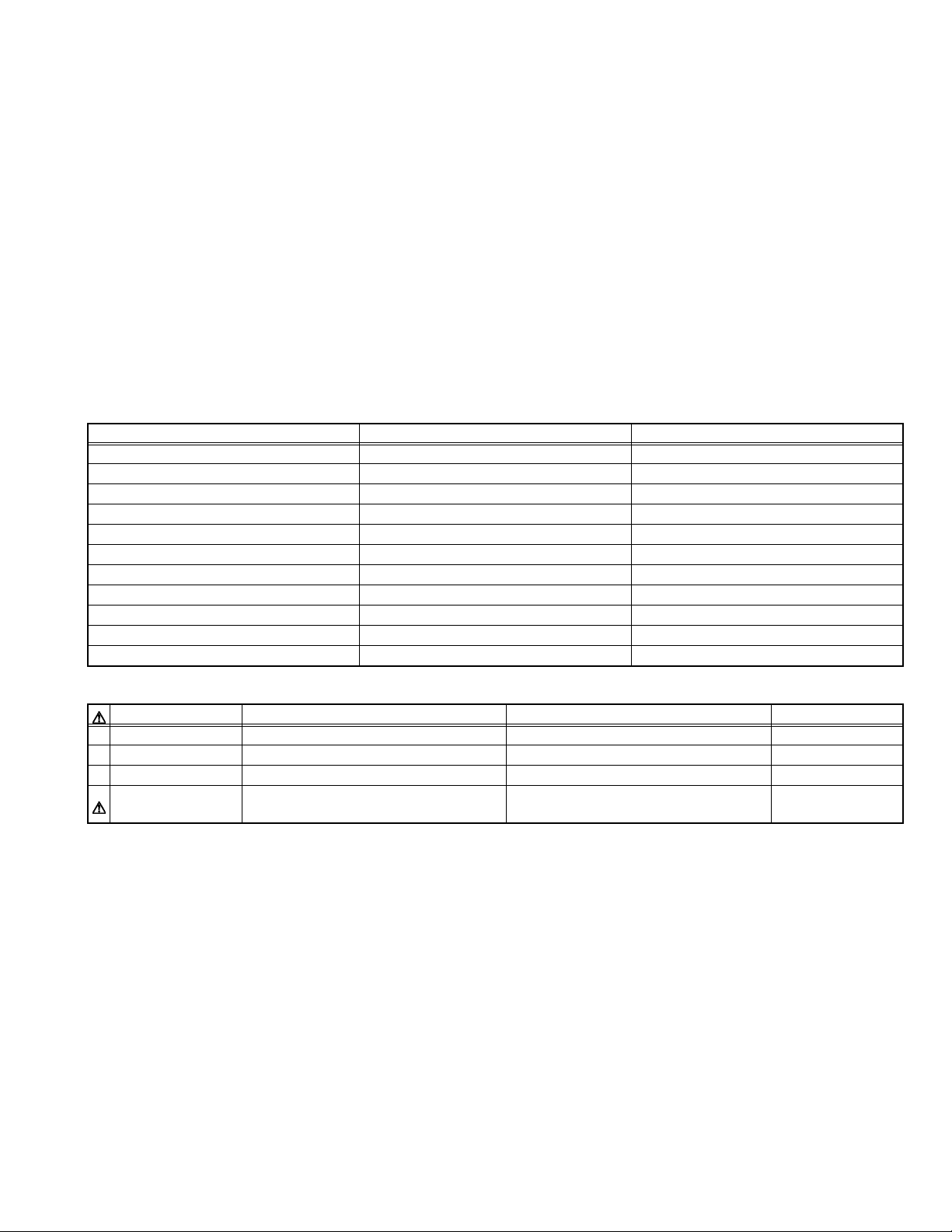
5.1.1 Protective sensor
Type Monitor objective Location Operating point Function
Thermal sensor
(Thermostat)
Thermal sensor (IC) Set interior
Thermal sensor (IC) Set exterior
Motor operation
detection circuit
5.1.2 Protective switch
Type Monitor objective Location Operating point Function
Interlock switch Lamp cover Optical block (Lamp section) Switch open Control by CPU
Photo sensor Top cover MAIN PWB ASS’Y Switch open Control by CPU
Lamp unit Optical block (Lamp section) 140°C AC line (one side) open
MAIN PWB ASS'Y IC728 70°C Power off by main CPU (emergency mode)
(Lamp area)
MAIN PWB ASS'Y IC727 62°C Power off by main CPU (emergency mode)
(Filter area)
Cooling fan Cooling fan interior Fan stop Power off by main CPU (emergency mode)
5.2 LED (INDICATOR) WARNING INDICATIONS
5.2.1 Led indication contents
If an abnormality occurs during operation (projection), the content of the problem can be determined from flashing LED indicators.
When an LED indicates, operation (projection) automatically stops and the cool-down mode (about 90 seconds) is entered (except for
No.1, No.3, No.4, No.5 and No.6), then the stand-by mode.
No. Flashing LED Flash time Warning cause (projector mode)
LAMP TEMP STAND BY OPERATE
1 zz0.5sec. Lamp not lighted cannot project
2 zz0.5sec.
3 ××0.5sec. Lamp terminal not contact
4 zz 0.5sec. Sub CPU circuit error
5 zz 0.25sec. Device drive circuit error
6 z 0.5sec. Set interior abnormally hot
7 zz 0.5sec.
8 zzzz0.5sec. Set internal cooling fan stopped (fan locked)
9 z 0.5sec. Lamp use time exceeds 2000 hours
z : Flashing together × : Flashing alternately
Lamp extinguishes during projection Lamp use time exceeds 2010 hours
Air intake temperature too high (exterior temperature
abnormal)
(No.PA019)1-29
Page 30

5.2.2 Mearsures during abnormality
In event of the following be sure to disconnect the power cord from the AC outlet, and reset the projector mode.
No. Abnormality Mode Measure Mode Cause
1 Lamp dose not light → Again supply power (press OPERATE button) OK Lamp lighting failure
NG Check lamp use dose not exceed 2000 hours YES Lamp use inhibited
NG Replace lamp unit OK Lamp defective
NG Replace LAMP BALLAST unit OK Igniter circuit faulty
2 Lamp extinguishes during
projection
Lamp use time exceeded → Replace lamp and reset the lamp use time OK Lamp use inhibited
3 Sub CPU operation faulty → Again supply power (press MAIN POWER
4 DD circuit operating faulty → Again supply power (press OPERATE button) OK Circuit operating error
6 Internal temperature
abnormally high
7 Out side temperature
abnormally high
8 Cooling fan stopped → Reinstall 713 connector OK Connector installation defective
9 Confirmation of DVI
activation
→ Revise installation mode (protect from shock,
vibration, etc)
NG Replace lamp unit OK Lamp defective
button)
NG Replace MAIN PWB ASS'Y OK Sub CPU failure
NG Replace MAIN PWB ASS'Y OK Device drive circuit failure
→ Avoid obstructing ventilation openings (intake
and exhaust)
NG Replace MAIN PWB ASS'Y OK Defective sensor and detection circuit
→ Ambient temperature of the unit should be
mode into specification within the limits
NG Replace MAIN PWB ASS'Y OK Defective sensor and detection circuit
NG Reinstall 705 connector OK Connector installation defective
NG Reinstall 706 connector OK Connector installation defective
NG Reinstall 707 connector OK Connector installation defective
NG Reinstall 714 connector OK Connector installation defective
NG Replace cooling fan OK Cooling fan defective
→ Temporarily disconnect power from projector
and PC. After making sure that DVI cable has
been properly connected, turn on power of
projector and PC, in turn.
NG Confirm that output of DVI terminal at graphic
board of PC has been set properly.
OK Installation mode (environment)
unfavorable
OK Circuit operating error
OK Circuit error or other fault
OK Circuit error or other fault
OK Improper connection of DVI cable
Wrong order of power on (Correct
order : 1. Projector 2. PC )
OK Improper setting of PC (DIV output)
1-30 (No.PA019)
Page 31

5.3 ERROR LOG (SELF-DIAGONOSIS RECORD AND INDICATION)
5.3.1 Outline
By using the special setting and adjustment software, data related to abnormal operation (history) stored in the projector can be load.
On the basis of contents "LED (INDICATOR) WARNING INDICATONS" set and lamp use time, internal and external temperature, and
other data prior to the previous usage time can be viewed as a table.
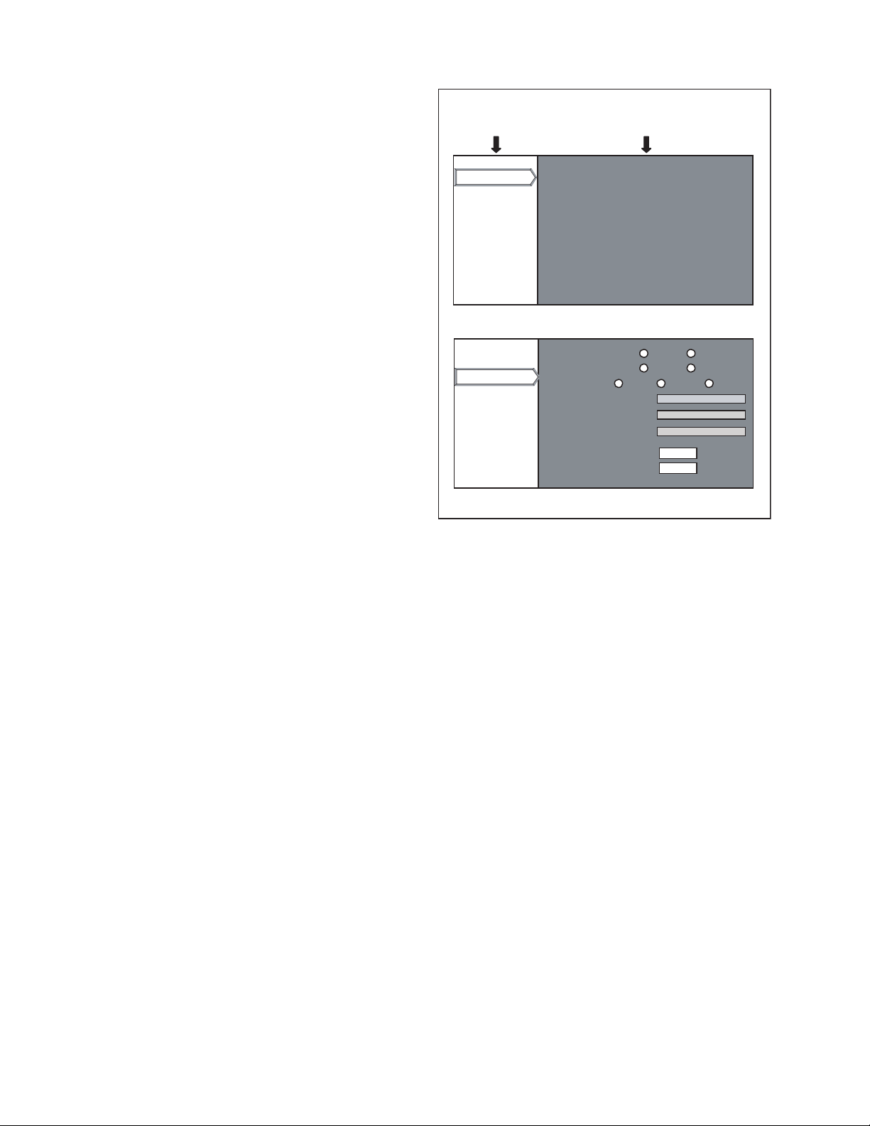
z HOW TO LOAD THE DATA FROM UNIT
(1) Install the software in a personal computer and connect
by RS-232C IN terminal (use cross cable).
(2) Set the projector to stand-by mode.
(3) Start the setting and adjustment software. The main
menu shown in Fig.1 appears.
(4) Click the [Error Log] button to show the screen indicated
in Fig.2.
(5) Click the [Receive Log Data] button to display the history.
z ERROR LOG SCREEN ITEMS
Item Displayed contents
Error Detection Error event code (10 types)
Wakeup Count Number of times operation mode reached
System Time Total time in operation mode until present
Lamp Time Total lamp lighted time until present
Slave Deg (Out) External temperature detected by sensor dur-
ing error event
Sub Deg (In) Internal temperature detected by sensor dur-
ing error event
Click
Fig.1 Start screen (main menu)
5.3.2 Error code
Error cord Detected condition Indicated LED
E01 Lamp can not light during shift from stand-by to operation mode STAND BY + LAMP (Blinking)
E02 Lamp use time exceeds 2000h LAMP (Blinking)
E03 Inter IC bus communication error (ACK receive error) Absent
E06 Lamp extinguishes during projection OPERATE + LAMP (Blinking)
E07 Cooling fan stops (fan lock) All (4 LEDs Blinking)
E08 Set internal temperature (lamp area) abnormally high (Exceeds 70°C) TEMP (Blinking)
E09 Set internal temperature (ventilation intake openings) abnormally high (Exceeds 62°C) STAND BY + TEMP (Blinking)
E10 Lamp use time exceeds 1900h LAMP(Light on)
E11 Error in device drive circuit operation LAMP + TEMP (Blinking)
E15 Come off lamp cover OPERATE + LAMP
E20 When the sleep time function operated and the lamp goes out Absent
5.3.3 Function
Button (item) Function Data process
Receive Receive data stored in projector and display < Error log > screen Projector to PC
Reset Delete all data stored in projector (reset) Projector internal
Clear Display Delete record (history) shown on < Error log > screen (delete computer side) PC internal
Save Save record (history) shown on < Error log > screen to file PC internal
Load Read record (history) stored in PC and display in < Error log > screen PC internal
Fig.2 <Error log> screen
(Alternately blinking)
(No.PA019)1-31
Page 32

VICTOR COMPANY OF JAPAN, LIMITED
ILA CENTER 12, 3-chome, Moriya-cho, kanagawa-ku, Yokohama, kanagawa-prefecture, 221-8528, Japan
(No.PA019)
Printed in Japan
VPT
 Loading...