

Page 1
ENGLISH FRANÇAIS ESPAÑOL
D-ILA PROJECTOR
PROJECTEUR D-ILA
PROYECTOR D-ILA
DLA-HD1
INSTRUCTIONS
MANUEL D’INSTRUCTIONS
MANUAL DE INSTRUCCIONES
Getting Started Preparation Basic Operation Settings Troubleshooting Others
For Customer use :
Enter below the serial No. which is
located on the bottom side of the
cabinet. Retain this information for
future reference.
Model No. DLA-HD1
Serial No.
Pour utilisation par le client :
Entrer ci-dessous le N° de série qui
est situé sous le boîtier. Garder
cette information comme référence
pour le futur.
N° de modèle DLA-HD1
N° de série
Instrucción para el cliente :
Introduzca a continuación el nº de
serie que aparece en la parte
inferior lateral de la caja. Conserve
esta información como referencia
para uso ulterior.
Modelo Nº DLA-HD1
Nº de serie
LCT2215-001C
Page 2
1
Getting Started
Safety Precautions
IMPORTANT INFORMATION
This product has a High Intensity
Discharge (HID) lamp that contains
mercury.
Disposal of these materials may be
regulated in your community due to
environmental considerations. For
disposal or recycling information please
contact your local authorities or for USA,
the Electronic Industries Alliance:
http://www.eiae.org.
WARNING:
TO PREVENT FIRE OR SHOCK HAZARDS, DO NOT
EXPOSE THIS APPLIANCE TO RAIN OR MOISTURE.
WARNING:
THIS APPARATUS MUST BE EARTHED.
CAUTION:
To reduce the risk of electric shock, do not remove
cover. Refer servicing to qualified service personnel.
This projector is equipped with a 3-blade grounding
type plug to satisfy FCC rule. If you are unable to insert
the plug into the outlet, contact your electrician.
FCC INFORMATION (U.S.A. only)
CAUTION:
Changes or modification not approved by JVC could
void the user’s authority to operate the equipment.
NOTE:
This equipment has been tested and found to comply
with the limits for Class B digital devices, pursuant to
Part 15 of the FCC Rules. These limits are designed to
provide reasonable protection against harmful
interference in a residential installation. This equipment
generates, uses, and can radiate radio frequency
energy and, if not installed and used in accordance with
the instructions, may cause harmful interference to
radio communications. However, there is no guarantee
that interference will not occur in a particular
installation. If this equipment does cause harmful
interference to radio or television reception, which can
be determined by turning the equipment off and on, the
user is encourage to try to correct the interference by
one or more of the following measures:
● Reorient or relocate the receiving antenna.
● Increase the separation between the equipment and
receiver.
● Connect the equipment into an outlet on a circuit
different from that to which the receiver is connected.
● Consult the dealer or an experienced radio/TV
technician for help.
MACHINE NOISE INFORMATION (Germany only)
Changes Machine Noise Information Ordinance 3.
GSGV, January 18, 1991: The sound pressure level at
the operator position is equal or less than 70 dB (A)
according to ISO 7779.
About the installation place
Do not install the projector in a place that cannot support
its weight securely.
If the installation place is not sturdy enough, the projector
could fall or overturn, possibly causing personal injury.
IMPORTANT SAFEGUARDS
Electrical energy can perform many useful functions. This
unit has been engineered and manufactured to assure
your personal safety. But IMPROPER USE CAN RESULT
IN POTENTIAL ELECTRICAL SHOCK OR FIRE
HAZARD. In order not to defeat the safeguards
incorporated into this product, observe the following basic
rules for its installation, use and service. Please read
these Important Safeguards carefully before use.
- All the safety and operating instructions should be read
before the product is operated.
- The safety and operating instructions should be retained
for future reference.
- All warnings on the product and in the operating
instructions should be adhered to.
- All operating instructions should be followed.
- Place the projector near a wall outlet where the plug can
be easily unplugged.
- Unplug this product from the wall outlet before cleaning.
Do not use liquid cleaners or aerosol cleaners. Use a
damp cloth for cleaning.
- Do not use attachments not recommended by the product
manufacturer as they may be hazardous.
- Do not use this product near water. Do not use
immediately after moving from a low temperature to high
temperature, as this causes condensation, which may
result in fire, electric shock, or other hazards.
- Do not place this product on an unstable cart, stand, or
table. The product may fall, causing serious injury to a
child or adult, and serious damage to the product. The
product should be mounted according to the
manufacturer’s instructions, and should use a mount
recommended by the manufacturer.
- When the product is used on a cart,
care should be taken to avoid quick
stops, excessive force, and uneven
surfaces which may cause the product
and cart to overturn, damaging
equipment or causing possible injury to
the operator.
2
Page 3
ENGLISH
Getting Started Preparation Basic Operation Settings Troubleshooting Others
- Slots and openings in the cabinet are provided for
ventilation. These ensure reliable operation of the product
and protect it from overheating. These openings must not
be blocked or covered. (The openings should never be
blocked by placing the product on bed, sofa, rug, or similar
surface. It should not be placed in a built-in installation
such as a bookcase or rack unless proper ventilation is
provided and the manufacturer’s instructions have been
adhered to.)
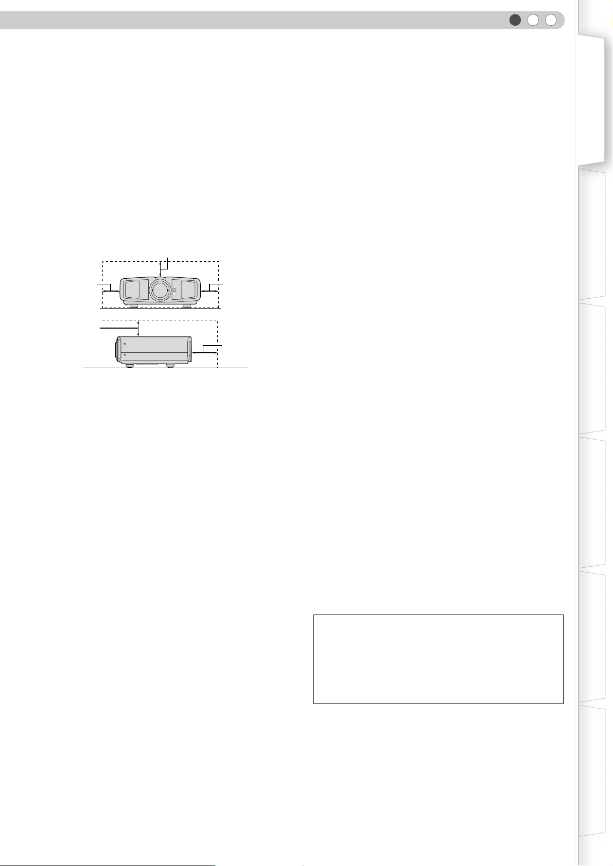
- To allow better heat dissipation, keep a clearance between
this unit and its surrounding as shown below. When this
unit is enclosed in a space of dimensions as shown below,
use an air-conditioner so that the internal and external
temperatures are the same.
150 mm and above
300 mm
and above
300 mm
and above
150 mm
and above
200 mm
and above
- This product should be operated only with the type of
power source indicated on the label. If you are not sure of
the type of power supply to your home, consult your
product dealer or local power company.
- This product is equipped with a three-wire plug. This plug
will fit only into a grounded power outlet. If you are unable
to insert the plug into the outlet, contact your electrician to
install the proper outlet. Do not defeat the safety purpose
of the grounded plug.
- Power-supply cords should be routed so that they are not
likely to be walked on or pinched by items placed upon or
against them. Pay particular attention to cords at doors,
plugs, receptacles, and the point where they exit from the
product.
- For added protection of this product during a lightning
storm, or when it is left unattended and unused for long
periods of time, unplug it from the wall outlet and
disconnect the cable system. This will prevent damage to
the product due to lightning and power line surges.
- Do not overload wall outlets, extension cords, or
convenience receptacles on other equipment as this can
result in a risk of fire or electric shock.
- Never push objects of any kind into this product through
openings as they may touch dangerous voltage points or
short out parts that could result in a fire or electric shock.
Never spill liquid of any kind on the product.
- Do not attempt to service this product yourself as opening
or removing covers may expose you to dangerous
voltages and other hazards. Refer all service to qualified
service personnel.
-
Unplug this product from the wall outlet and refer service to
qualified service personnel under the following conditions:
a) When the power supply cord or plug is damaged.
b) If liquid has been spilled, or objects have fallen on the product.
c) If the product has been exposed to rain or water.
d) If the product does not operate normally by following the
operating instructions. Adjust only those controls that are
covered by the Operation Manual, as an improper adjustment
of controls may result in damage and will often require
extensive work by a qualified technician to restore the product
to normal operation.
e) If the product has been dropped or damaged in any way.
f) When the product exhibits a distinct change in performance -
this indicates a need for service.
- When replacement parts are required, be sure the service
technician has used replacement parts specified by the
manufacturer or with same characteristics as the original
part. Unauthorized substitutions may result in fire, electric
shock, or other hazards.
-
Upon completion of any service or repairs to this product,
ask the service technician to perform safety checks to
determine that the product is in proper operating condition.
- The product should be placed more than one foot away
from heat sources such as radiators, heat registers,
stoves, and other products (including amplifiers) that
produce heat.
- When connecting other products such as VCR’s, and DVD
players, you should turn off the power of this product for
protection against electric shock.
- Do not place combustibles behind the cooling fan. For
example, cloth, paper, matches, aerosol cans or gas
lighters that present special hazards when over heated.
- Do not look into the projection lens while the illumination
lamp is turned on. Exposure of your eyes to the strong
light can result in impaired eyesight.
- Do not look into the inside of this unit through vents
(ventilation holes), etc. Do not look at the illumination lamp
directly by opening the cabinet while the illumination lamp
is turned on. The illumination lamp also contains ultraviolet
rays and the light is so powerful that your eyesight can be
impaired.
- Do not drop, hit, or damage the light-source lamp (lamp
unit) in any way. It may cause the light-source lamp to
break and lead to injuries. Do not use a damaged light
source lamp. If the light-source lamp is broken, ask your
dealer to repair it. Fragments from a broken light-source
lamp may cause injuries.
- The light-source lamp used in this projector is a high
pressure mercury lamp. Be careful when disposing of the
lightsource lamp. If anything is unclear, please consult
your dealer.
- Do not ceiling-mount the projector to a place which tends
to vibrate; otherwise, the attaching fixture of the projector
could be broken by the vibration, possibly causing it to fall
or overturn, which could lead to personal injury.
- Use only the accessory cord designed for this product to
prevent shock.
*DO NOT allow any unqualified person to install the
unit.
Be sure to ask your dealer to install the unit (e.g.
attaching it to the ceiling) since special technical
knowledge and skills are required for installation. If
installation is performed by an unqualified person, it
may cause personal injury or electrical shock.
3
Page 4
1
Getting Started
Safety Precautions (Continued)
POWER CONNECTION POWER CONNECTION
The power supply voltage rating of this product is
AC120 V, AC110 V – AC240 V, the power cord attached
conforms to the following power supply voltage. Use
only the power cord designated by our dealer to ensure
Safety and EMC.
When it is used by other power supply voltage, power
cable must be changed.
Ensure that the power cable used for the projector is the
correct type for the AC outlet in your country. Consult
your product dealer.
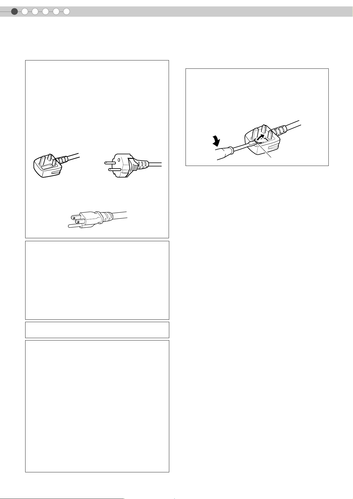
Power cord
(United Kingdom only)
HOW TO REPLACE THE FUSE:
When replacing the fuse, be sure to use only a correctly
rated approved type, re-fit the fuse cover.
IF IN DOUBT —— CONSULT A COMPETENT ELECTRICIAN.
Open the fuse compartment with the blade screwdriver,
and replace the fuse.
(* An example is shown in the illustration below.)
Fuse
For United Kingdom For European continent
Power supply voltage: AC 120 V
WARNING:
Do not cut off the main plug from this equipment.
If the plug fitted is not suitable for the power points in
your home or the cable is too short to reach a power
point, then obtain an appropriate safety approved
extension lead or adapter or consult your dealer.
If nonetheless the mains plug is cut off, dispose of the
plug immediately, to avoid a possible shock hazard by
inadvertent connection to the main supply. If a new main
plug has to be fitted, then follow the instruction given
below.
WARNING:
THIS APPARATUS MUST BE EARTHED.
IMPORTANT:
The wires in the mains lead on this product are colored
in accordance with the following cord:
Green-and-yellow : Earth
Blue : Neutral
Brown : Live
As these colors may not correspond with the colored
making identifying the terminals in your plug, proceed
as follows:
The wire which is colored green-and-yellow must be
connected to the terminal which is marked M with the
letter E or the safety earth or colored green or greenand-yellow.
The wire which is colored blue must be connected to the
terminal which is marked with the letter N or colored
black.
The wire which is colored brown must be connected to
the terminal which is marked with the letter L or colored
red.
countries
Power cord
4
Page 5
ENGLISH
Dear Customer,
This apparatus is in conformance with the valid European directives and standards regarding electromagnetic
compatibility and electrical safety.
European representative of Victor Company of Japan, Limited is:
JVC Technology Centre Europe GmbH
Postfach 10 05 52
61145 Friedberg
Germany
Getting Started Preparation Basic Operation Settings Troubleshooting Others
5
Page 6
1
Getting Started
Safety Precautions (Continued)
ENGLISH
Information for Users on Disposal of Old
Equipment
Attention:
This symbol is only
valid in the European
Union.
[European Union]
This symbol indicates that the electrical and electronic equipment
should not be disposed as general household waste at its end-oflife. Instead, the product should be handed over to the applicable
collection point for the recycling of electrical and electronic
equipment for proper treatment, recovery and recycling in
accordance with your national legislation.
By disposing of this product correctly, you will help to conserve
natural resources and will help prevent potential negative effects
on the environment and human health which could otherwise be
caused by inappropriate waste handling of this product. For more
information about collection point and recycling of this product,
please contact your local municipal office, your household waste
disposal service or the shop where you purchased the product.
Penalties may be applicable for incorrect disposal of this waste, in
accordance with national legislation.
(Business users)
If you wish to dispose of this product, please visit our web page
www.jvc-europe.com
the product.
to obtain information about the take-back of
[Other Countries outside the European Union]
If you wish to dispose of this product, please do so in accordance
with applicable national legislation or other rules in your country
for the treatment of old electrical and electronic equipment.
DEUTSCH
FRANÇAIS
Informations relatives à l’élimination des
appareils usagés, à l’intention des utilisateurs
Attention:
Ce symbole n’est
reconnu que dans
l’Union européenne.
[Union européenne]
Lorsque ce symbole figure sur un appareil électrique et
électronique, cela signifie qu’il ne doit pas être éliminé en tant que
déchet ménager à la fin de son cycle de vie. Le produit doit être
porté au point de pré-collecte approprié au recyclage des
appareils électriques et électroniques pour y subir un traitement,
une récupération et un recyclage, conformément à la législation
nationale.
En éliminant correctement ce produit, vous contriburez à la
conservation des ressources naturelles et à la prévention des
éventuels effets négatifs sur l’environnement et la santé humaine,
pouvant être dus à la manipulation inappropriée des déchets de ce
produit. Pour plus d’informations sur le point de pré-collecte et le
recyclage de ce produit, contactez votre mairie, le service
d’évacuation des ordures ménagères ou le magasin dans lequel
vous avez acheté le produit.
Des amendes peuvent être infligées en cas d’élimination
incorrecte de ce produit, conformément à la législation nationale.
(Utilisateurs professionnels)
Si vous souhaitez éliminer ce produit, visitez notre page Web
www.jvc-europe.com
récupération.
afin d’obtenir des informations sur sa
[Pays ne faisant pas partie de l’Union européenne]
Si vous souhaitez éliminer ce produit, faites-le conformément à la
législation nationale ou autres règles en vigueur dans votre pays
pour le traitement des appareils électriques et électroniques
usagés.
Benutzerinformationen zur Entsorgung alter
Geräte
Hinweis:
Dieses Symbol ist nur
in der Europäischen
Uniongültig.
[Europäische Union]
Dieses Symbol zeigt an, dass das elektrische bzw. elektronische
Gerät nicht als normaler Haushaltsabfall entsorgt werden soll.
Stattdessen sollte das Produkt zur fachgerechten Entsorgung,
Weiterverwendung und Wiederverwertung in Übereinstimmung mit
der Landesgesetzgebung einer entsprechenden Sammelstelle für
das Recycling elektrischer und elektronischer Geräte zugeführt
werden.
Die korrekte Entsorgung dieses Produkts dient dem Umweltschutz
und verhindert mögliche Schäden für die Umwelt und die
menschliche Gesundheit, welche durch unsachgemäße Behandlung
des Produkts auftreten können. Weitere Informationen zu
Sammelstellen und dem Recycling dieses Produkts erhalten Sie bei
Ihrer Gemeindeverwaltung, Ihrem örtlichen
Entsorgungsunternehmen oder in dem Geschäft, in dem Sie das
Produkt gekauft haben.
Für die nicht fachgerechte Entsorgung dieses Abfalls können
gemäß der Landesgesetzgebung Strafen ausgesprochen werden.
(Geschäftskunden)
Wenn Sie dieses Produkt entsorgen möchten, besuchen Sie bitte
unsere Webseite www.jvc-europe.com
Rücknahme des Produkts zu erhalten.
, um Informationen zur
[Andere Länder außerhalb der Europäischen Union]
Wenn Sie dieses Produkt entsorgen möchten, halten Sie sich
dabei bitte an die entsprechenden Landesgesetze und andere
Regelungen in Ihrem Land zur Behandlung elektrischer und
elektronischer Geräte.
NEDERLANDS
Informatie voor gebruikers over het weggooien
van oude apparatuur
Let op:
Dit symbool is alleen
geldig in de
Europese Unie.
[Europese Unie]
Deze markering geeft aan dat de elektrische en elektronische
apparatuur bij het einde van de gebruiksduur niet bij het
huishoudelijk afval mag worden gegooid. Het product moet in
plaats daarvan worden ingeleverd bij het relevante
inzamelingspunt voor hergebruik van elektrische en
elektronische apparatuur, voor juiste verwerking, terugwinning en
hergebruik in overeenstemming met uw nationale wetgeving.
Door dit product naar het inzamelingspunt te brengen, werkt u
mee aan het behoud van natuurlijke hulpbronnen en met het
voorkomen van potentiële negatieve effecten op het milieu en de
volksgezondheid, die anders veroorzaakt zouden kunnen worden
door onjuiste afvalverwerking van dit product. Neem voor meer
informatie over inzamelingspunten en hergebruik van dit product
contact op met de gemeente in uw woonplaats, het
afvalverwerkingsbedrijf of de winkel waar u het product hebt
aangeschaft.
Er kunnen boetes gelden voor een onjuiste verwijdering van dit
afval, in overeenstemming met de nationale wetgeving.
(Zakelijke gebruikers)
Bezoek als u dit product wilt weggooien onze website
www.jvc-europe.com
product.
voor informatie over het terugnemen van het
[Landen buiten de Europese Unie]
Wanneer u dit product wilt verwijderen, houdt u dan aan de
geldende nationale wetgeving of andere regels in uw land voor
de verwerking van oude elektrische en elektronische apparatuur.
6
Page 7
ENGLISH
Getting Started Preparation Basic Operation Settings Troubleshooting Others
ESPAÑOL
Información para los usuarios sobre la
eliminación de equipos usados
Atención:
Este símbolo sólo es
válido en la Unión
Europea.
[Unión Europea]
Este símbolo indica que los aparatos eléctricos y electrónicos no
deben desecharse junto con la basura doméstica al final de su vida
útil. El producto deberá llevarse al punto de recogida
correspondiente para el reciclaje y el tratamiento adecuado de
equipos eléctricos y electrónicos de conformidad con la legislación
nacional.
Si desecha el producto correctamente, estará contribuyendo a
conservar los recursos naturales y a prevenir los posibles efectos
negativos en el medio ambiente y en la salud de las personas
que podría causar el tratamiento inadecuado del producto
desechado. Para obtener más información sobre el punto de
recogida y el reciclaje de este producto, póngase en contacto
con su oficina municipal, su servicio de recogida de basura
doméstica o la tienda en la que haya adquirido el producto.
De acuerdo con la legislación nacional, podrían aplicarse multas
por la eliminación incorrecta de estos desechos.
(Empresas)
Si desea desechar este producto, visite nuestra página Web
www.jvc-europe.com
retirada del producto.
para obtener información acerca de la
[Otros países no pertenecientes a la Unión
Europea]
Si desea desechar este producto, hágalo de conformidad con la
legislación nacional vigente u otras normativas de su país para el
tratamiento de equipos eléctricos y electrónicos usados.
PORTUGUÊS
Informações para os Utilizadores sobre a
Eliminação de Equipamento Antigo
Atenção:
Este símbolo apenas é
válido na União
Europeia.
[União Europeia]
Este símbolo indica que o equipamento eléctrico e electrónico
não deve ser eliminado como um resíduo doméstico geral, no fim
da respectiva vida útil. Pelo contrário, o produto deve ser
entregue num ponto de recolha apropriado, para efectuar a
reciclagem de equipamento eléctrico e electrónico e aplicar o
tratamento, recuperação e reciclagem adequados, de acordo
com a respectiva legislação nacional.
Ao eliminar este produto da forma correcta, ajudará a conservar
recursos naturais e ajudará a evitar potenciais efeitos negativos
no ambiente e saúde humana, que poderiam ser causados pelo
tratamento residual inadequado deste produto. Para mais
informações sobre o ponto de recolha e reciclagem deste
produto, contacte a respectiva entidade local, o serviço de
eliminação de resíduos ou a loja onde adquiriu o produto.
Caso estes resíduos não sejam correctamente eliminados,
poderão ser aplicadas penalizações, em conformidade com a
respectiva legislação nacional.
(utilizadores profissionais)
Se pretender eliminar este produto, visite a nossa página da web
em www.jvc-europe.com
devolução do produto.
para obter informações sobre a
[Outros países fora da União Europeia]
Se pretender eliminar este produto, faça-o de acordo com a
legislação nacional aplicável ou outras regras no seu país para o
tratamento de equipamento eléctrico e electrónico velho.
ITALIANO
Informazioni per gli utenti sullo smaltimento
delle apparecchiature obsolete
Attenzione:
Questo simbolo è
valido solo nell’Unione
Europea.
[Unione Europea]
Questo simbolo indica che l’apparecchiatura elettrica ed elettronica
a cui è relativo non deve essere smaltita tra i rifiuti domestici generici
alla fine della sua vita utile. Il prodotto, invece, va consegnato a un
punto di raccolta appropriato per il riciclaggio di apparecchiature
elettriche ed elettroniche, per il trattamento, il recupero e il riciclaggio
corretti, in conformità alle proprie normative nazionali.
Mediante lo smaltimento corretto di questo prodotto, si contribuirà a
preservare le risorse naturali e a prevenire potenziali effetti negativi
sull’ambiente e sulla salute umana che potrebbero essere provocati,
altrimenti, da uno smaltimento inappropriato del prodotto. Per
ulteriori informazioni sul punto di raccolta e il riciclaggio di questo
prodotto, contattare la sede comunale locale, il servizio di
smaltimento rifiuti domestici o il negozio in cui si è acquistato il
prodotto.
L’utente è responsabile del conferimento dell’apparecchio a fina
vita alle appropriate strutture di raccolta, pena le sanzioni
previste dalla vigente legislazione sui rifiuti.
(Per gli utenti aziendali)
Qualora si desideri smaltire questo prodotto, visitare la nostra
pagina web www.jvc-europe.com
ritiro del prodotto.
per ottenere informazioni sul
[Per altre nazioni al di fuori dell’Unione Europea]
Qualora si desideri smaltire questo prodotto, effettuare lo
smaltimento in conformità alla normativa nazionale applicabile o
alle altre leggi della propria nazione relative al trattamento delle
apparecchiature elettriche ed elettroniche obsolete.
ΕΛΛΗΝΙΚΑ
Πληροφορίες σχετικά µε την απόρριψη
εξοπλισµού
Προσοχή:
Αυτή η σήµανση ισχύει
µόνο για την
Ευρωπαϊκή Ένωση.
[Ευρωπαϊκή Ένωση]
Αυτή η σήµανση υποδηλώνει ότι ο ηλεκτρικός και ηλεκτρονικός
εξοπλισµός δεν πρέπει να απορριφθεί ως κοινό οικιακό
απόρριµµα. Αντ' αυτού, το προϊόν πρέπει να παραδοθεί στο
ανάλογο σηµείο περισυλλογής για την ανακύκλωση των
ηλεκτρικών και ηλεκτρονικών µερών και την κατάλληλη
επεξεργασία, σύµφωνα µε τη νοµοθεσία της χώρας σας.
Η σωστή απόρριψη αυτού το προϊόντος βοηθάει στη διαφύλαξη
των φυσικών πόρων και στην αποφυγή αρνητικών επιπτώσεων
στο περιβάλλον και στην ανθρώπινη υγεία, κάτι που ενδέχεται να
προκληθεί από την ακατάλληλη διαχείριση αυτού του προϊόντος
ως απόρριµµα. Για περισσότερες πληροφορίες σχετικά µε τα
σηµεία περισυλλογής και ανακύκλωσης αυτού του προϊόντος,
επικοινωνήστε µε τα γραφεία της τοπικής αυτοδιοίκησης, την
υπηρεσία περισυλλογής απορριµµάτων ή το κατάστηµα από το
οποίο αγοράσατε το προϊόν.
Ανάλογα µε τη νοµοθεσία της χώρας σας, ενδέχεται να
επιβληθούν κυρώσεις σε περίπτωση λανθασµένης απόρριψης
αυτού του προϊόντος.
(Επιχειρήσεις)
Αν επιθυµείτε να απορρίψετε αυτό το προϊόν, επισκεφτείτε το
διαδικτυακό µας τόπο www.jvc-europe.com
πληροφορίες σχετικά µε την επιστροφή του προϊόντος.
για περισσότερες
[Άλλες χώρες εκτός Ευρωπαϊκής Ένωσης]
Αν επιθυµείτε να απορρίψετε αυτό το προϊόν, πρέπει να
τηρήσετε την ισχύουσα εθνική νοµοθεσία ή όποιους άλλους
κανονισµούς για τη χώρα σας για την απόρριψη ηλεκτρικού και
ηλεκτρονικού εξοπλισµού.
7
Page 8
1
Getting Started
Safety Precautions (Continued)
DANSK
Brugerinformation om bortskaffelse af gammelt
udstyr
Bemærk:
Dette symbol er kun
gyldigt i EU.
[EU]
Elektriske produkter og elektroniske apparater med dette symbol
må ikke afhændes på samme måde som almindeligt
husholdningsaffald, når det skal smides ud. I stedet skal
produktet indleveres på det relevante indsamlingssted for
elektriske apparater og elektronisk udstyr, hvor det vil blive
håndteret korrekt og efterfølgende genanvendt og recirkuleret i
henhold til de love, der gælder i dit land.
Ved at bortskaffe dette produkt korrekt, medvirker du til at bevare
naturens ressourcer samt forhindre eventuelle negative
påvirkninger af miljøet og folkesundheden, der ellers kunne
forårsages ved forkert affaldshåndtering af dette produkt. Mere
information om indsamlingssteder og genanvendelse af dette
produkt kan du få ved at kontakte din lokale kommune, dit
renovationsselskab eller den forretning, hvor du har købt
produktet.
Ukorrekt bortskaffelse af dette affald kan være strafbar ifølge
lovgivningen i nogle lande.
(Professionelle brugere)
Hvis du ønsker at bortskaffe dette produkt, kan du på vores
webside www.jvc-europe.com
produktet.
få information om tilbagetagning af
[Lande uden for EU]
Hvis du ønsker at bortskaffe dette produkt, bedes du gøre det i
overensstemmelse med gældende lovgivning eller andre regler i
dit land for behandling af gammelt elektrisk og elektronisk udstyr.
SVENSKA
Information till användare gällande kassering av
gammal utrustning
Tänk på:
Att denna symbol
endast gäller inom den
Europeiska
gemenskapen.
[Europeiska gemenskapen]
Denna symbol anger att elektrisk och elektronisk utrustning inte
ska kasseras som vanligt hushållsavfall, när de inte ska
användas mer. Istället ska produkten lämnas in på lämplig
återvinningsstation för elektrisk eller elektronisk utrustning, så att
den kan tas om hand och återvinnas i enlighet med ert lands
lagstiftning.
Genom att avyttra denna profukt på rätt sätt, bidrar du till att
bevara naturen och förhindrar potentiellt negativa effekter på
miljön och den mänskiliga hälsan, som annars kan bli resultatet
vid felaktig hantering av denna produkt. Kontakta ditt
kommunkontor, det företag som hanterar dina hushållssopor eller
butiken där du köpt produkten, för mer information om
återvinningscentraler.
Det kan hända att du bötfälls i enlighet med ert lands lagstiftning
om detta avfall kasseras på fel sätt.
(Företagsanvändare)
Om ni vill kassera denna produkt, besök vår webbsida
www.jvc-europe.com
produkten.
för att få information om returnering av
[Övriga länder utanför den Europeiska
gemenskapen]
Om du vill kassera denna produkt, ska detta göras i enlighet med
gällande lagstiftning i landet, eller enligt andra bestämmelser i
ditt land, för behandling av gammal elektrisk eller elektronisk
utrustning.
SUOMI
Tietoja käyttäjille vanhojen laitteiden
hävittämisestä
Huomio:
Tämä symboli on
voimassa vain
Euroopan unionissa.
[Euroopan unioni]
Tämä symboli tarkoittaa, että sähkö- ja elektroniikkalaitteita ei
tule laittaa talousjätteisiin, kun ne poistetaan käytöstä. Sen sijaan
tuotteet tulee toimittaa asianmukaiseen sähkö- ja
elektroniikkalaitteiden kierrätyspisteeseen, jossa ne käsitellään
uusiokäyttöä ja kierrätystä varten paikallisen lainsäädännön
mukaan.
Kun hävität tuotteen asianmukaisella tavalla, autat säästämään
luonnonvaroja ja estämään mahdollisia ympäristö- ja
terveyshaittoja, joita voisi aiheutua tämän tuotteen
vääränlaisesta hävittämisestä. Lisätietoja keräyspisteistä ja
tämän tuotteen kierrätyksestä saat paikkakuntasi viranomaisilta,
kotitalousjätteiden keräyksestä huolehtivasta yrityksestä tai
liikkeestä, josta ostit tuotteen.
Tuotteen vääränlaisesta hävittämisestä voi seurata paikallisen
lainsäädännön mukaisia rangaistuksia.
(Yrityskäyttäjät)
Jos haluat hävittää tämän tuotteen, web-sivustoltamme
osoitteessa www.jvc-europe.com
palautuksesta.
löydät tietoja käytetyn tuotteen
[Muut maat Euroopan unionin ulkopuolella]
Jos haluat hävittää tämän tuotteen, tee se kansallisen
lainsäädännön tai muiden maassasi voimassa olevien
määräysten mukaan, jotka koskevat vanhojen sähkö- ja
elektroniikkalaitteiden käsittelyä.
NORSK
Informasjon til brukerne om kassering av
gammelt utstyr
OBS!
Dette symbolet er kun
gyldig i den Europeiske
Union og i EFTA-landene
Norge, Island og Sveits.
[Europeiske Union]
Dette symbolet betyr at det elektriske eller elektroniske utstyret
ikke skal kasseres som vanlig husholdningsavfall når det har
nådd slutten av sin levetid. I stedet skal produktet leveres til en
passende mottaksstasjon for kasserte elektriske og elektroniske
produkter, slik at disse kan behandles, gjenvinnes og resirkuleres
i samsvar med nasjonal lovgivning.
Hvis du kasserer dette produktet på riktig måte, bidrar til du til å
bevare naturlige ressurser og til å motvirke de negative
virkningene på miljøet og den menneskelige helse som kan
oppstå hvis produktet kasseres på feil måte. Hvis du vil ha mer
informasjon om mottaksstasjoner og gjennvinning av dette
produktet, kan du ta kontakt med kommunen din,
renovasjosselskapet ditt eller den forhandleren du kjøpte
produktet av.
Feilaktig kassering av dette utstyret kan kanskje bøtelegges,
avhengig av nasjonale lover og regler.
(Bedriftsbrukere)
Hvis du ønsker å kassere dette produktet, kan du gå til
hjemmesiden vår på www.jvc-europe.com
for å få informasjon om retur av dette produktet.
eller www.elretur.no
[Andre land utenfor EU]
Hvis du ønsker å kassere dette produktet, må du gjøre det i
samsvar med gjeldende nasjonal lovgivning eller andre regler
som gjelder i landet ditt når det gjelder behandling av gammelt
elektrisk og elektronisk utstyr.
8
Page 9

ENGLISH
Getting Started Preparation Basic Operation Settings Troubleshooting Others
РУССКИЙ
Информация для пользователей,
выбрасывающих старое оборудование
Внимание:
Действие этого символа
распространяется
только на Европейский
Союз.
[Европейский Союз]
Это символ указывает, что после окончания срока службы
соответствующего электрического или электронного
оборудования, нельзя выбрасывать его вместе с обычным
бытовым мусором. Вместо этого, оно подлежит сдаче на
утилизацию в соответствующий пункт приема
электрического и электронного оборудования для
последующей переработки и утилизации в соответствии с
национальным законодательством.
Обеспечивая правильную утилизацию данного продукта, Вы
помогаете сберечь природные ресурсы и предотвращаете
ущерб для окружающей среды и здоровья людей, который
возможен в случае ненадлежащего обращения. Более
подробную информацию о пунктах приема и утилизации
данного продукта можно получить в местных
муниципальных органах, на предприятии по вывозу
бытового мусора или по месту приобретения продукта.
Нарушение правил утилизации данного типа отходов в
соответствии с национальным законодательством является
административным правонарушением.
(Организации-пользователи)
Прежде чем выбрасывать данный продукт, ознакомьтесь с
информацией о приемке отработавших продуктов,
приведенной на веб-узле www.jvc-europe.com
.
[Страны, не входящие в Европейский Союз]
Если Вы собираетесь выбросить данный продукт,
руководствуйтесь национальным законодательством или
другими правилами, действующими в Вашей стране по
отношению к переработке старого электрического и
электронного оборудования.
ČESKY
Informace pro uživatele k likvidaci starého
zařízení
Upozornění:
Te n to s ym b ol j e p la t ný
jen v Evropské unii.
[Evropská unie]
Tento symbol udává, že elektrické a elektronické vybavení nesmí
být po skončení životnosti likvidován jako běžný komunální
odpad. Produkt musí být předán na příslušném sběrném místě k
správnému zpracování, regeneraci a recyklaci elektrického a
elektronického vybavení. Musí být zlikvidován správně v souladu
s národními předpisy vaší země.
Správnou likvidací tohoto produktu pomůžete zachovat přírodní
zdroje a napomáháte prevenci potenciálních negativních dopadů
na životní prostředí a lidské zdraví, což by mohly být důsledky
nesprávné likvidace tohoto produktu. Podrobnější informace o
sběrném místě a recyklaci tohoto produktu si vyžádejte od
místních úřadů, podniku zabývajícího se likvidací komunálních
odpadů ve vašem místě nebo obchodu, kde jste produkt
zakoupili.
Nesprávná likvidace tohoto odpadu může mít za následek postih
podle národní legislativy.
(Firemní uživatelé)
Přejete-li si tento produkt zlikvidovat, navštivte prosím naši
webovou stránku www.jvc-europe.com
možnosti vrácení produktu.
, kde získáte informace o
[Ostatní země mimo Evropskou unii]
Přejete-li si zlikvidovat tento produkt, proveďte to prosím v
souladu s příslušnými národními zákony nebo jinými předpisy
platnými ve vaší zemi, které se vztahují k likvidaci starého
elektrického a elektronického vybavení.
MAGYAR
POLSKI
Informacja dla użytkowników, dotycząca
utylizacji niesprawnych urządzeń
Uwaga:
Taki symbol jest ważny
tylko w Unii Europejskej.
[Kraje Unii Europejskiej]
Symbol przedstawiony obok oznacza, że urządzeń
elektrycznych i elektronicznych po zakończeniu okresu ich
eksploatacji nie należy wyrzucać razem z odpadami
gospodarczymi. Należy je natomiast przekazać do punktu
odbioru urządzeń elektrycznych i elektronicznych w celu ich
odpowiedniego przerobu, odzysku i utylizacji zgodnie z
krajowym ustawodawstwem.
Dbając o prawidłową utylizację produktu, przyczyniasz się do
ochrony zasobów naturalnych i zmniejszasz negatywny wpływ
oddziaływania na środowisko i zdrowie ludzi, zagrożone
niewłaściwym traktowaniem odpadów elektronicznych.
Szczegółowe informacje dotyczące punktów zbiórki i
powtórnego przerobu odpadów można uzyskać u władz
lokalnych, w firmach zajmujących się zagospodarowaniem
odpadów lub w sklepie z artykułami elektronicznymi.
Zgodnie z krajowym ustawodawstwem w przypadku nieprawidłowego
usuwania wspomnianych odpadów mogą być nakładane kary.
(Użytkownicy biznesowi)
Jeśli zaszła potrzeba pozbycia się niniejszego produktu, prosimy
zajrzeć na strony www.jvc-europe.com
o możliwości jego odbioru.
, aby uzyskać informacje
[Kraje poza Unią Europejską]
W razie konieczności pozbycia się niniejszego produktu prosimy
postępować zgodnie z lokalnymi przepisami lub innymi zasadami
postępowania ze zużytym sprzętem elektrycznymi i elektronicznymi.
Felhasználói tájékoztató az elhasznált
berendezések ártalmatlanításáról
Figyelem!
Ez a szimbólum csak az
Európai Unióban
érvényes.
[Európai Unió]
Ez a szimbólum azt jelzi, hogy az elektromos és elektronikus
berendezést a hasznos élettartama végén nem szabad
háztartási szemétként kezelni. Ehelyett a terméket a megfelelő,
elektromos és elektronikus berendezések hulladékainak
hasznosítására szakosodott gyűjtőhelyre kell vinni, hogy a
nemzeti törvényeknek megfelelően történjék kezelése,
visszanyerése és újrahasznosítása.
A termék megfelelő ártalmatlanításával segít megőrizni a
természetes erőforrásokat és megelőzheti azokat a környezetre
és az egészségre gyakorolt ártalmas hatásokat, amelyeket a
termék hulladékának helytelen kezelése egyébként okozhat,
továbbá csökkenti az elektromos berendezésekből származó
hulladékok mennyiségét és segíti az újrahasznosítást és
újrafeldolgozást.
A nemzeti törvények értelmében az ilyen hulladék helytelen
ártalmatlanítása esetén büntetést szabhatnak ki.
(Üzleti felhasználók)
Amennyiben ártalmatlanítani kívánja ezt a terméket, kérjük,
látogasson el weboldalunkra: www.jvc-europe.com
tájékoztatást kaphat a termék visszavételével kapcsolatban.
, ahol
[Az Európai Unión kívüli országok]
Amennyiben ártalmatlanítani kívánja ezt a terméket, kérjük, a
megfelelő nemzeti jogszabályok, illetve az Ön országának az
elektromos és elektronikus berendezések hulladékának
kezelésére vonatkozó, egyéb szabályai szerint végezze.
9
Page 10
Main Features
Supports Multiple Digital
Devices
z
Comes with a dual HDMI terminal that
allows digital transmission of high
definition signals. (pP18)
10
Page 11

Beautiful Images on Big Screen
z Enjoy smooth and high resolution video images with no
visible grid, brought about by full high definition resolution
of 1920 c 1080 pixels. (pP24)
Getting Started Preparation Basic Operation Settings Troubleshooting Others
Perfect for Any Location
z Comes with an 80 % vertical and 34 % horizontal
lens shift function. (pP22)
11
Page 12

1
Getting Started
Contents
Getting Started
Safety Precautions................................................2
Main Features ...................................................10
Contents............................................................12
How to Read this Manual/
Accessories/Optional Accessories.....................13
About this Manual.........................................................13
Check the Accessories....................................................13
Optional Accessories .....................................................13
Controls and Features ........................................14
How to Use the Remote Control...........................17
Loading Batteries...........................................................17
Effective Range of Remote Control Unit............................17
Preparation
Selecting Connecting Devices..............................18
Connecting........................................................19
Connecting via Video Cable...........................................19
Connecting via S-video Cable ........................................19
Connecting via HDMI Cable Or
HDMI-DVI Conversion Cable........................................20
Connecting via Component Video Cable .........................20
Connecting via SCART-RCA Cable..................................21
Connecting via RGB Video Cable ...................................21
Troubleshooting
Troubleshooting.................................................38
What to Do When These Messages
Are Displayed .................................................40
About Warning Indicators..................................41
Actions to Be Taken for Warning Mode .......................... 41
Replacing the Lamp ...........................................42
Procedure for Lamp Replacement ................................... 42
Resetting Lamp Time...................................................... 44
Cleaning and Replacing the Filter........................45
Others
RS-232C Interface .............................................46
RS-232C Specifications ................................................. 46
Command Format ......................................................... 46
RS-232C Communication Examples................................ 49
Copyright and Caution.......................................50
About Trademarks and Copyright .................................. 50
Caution........................................................................ 50
Mounting this Unit......................................................... 51
Specifications ....................................................52
Dimensions................................................................... 53
Installing the Projector and Screen.......................22
Screen Size and Projection Distance................................23
Basic Operation
Projecting Image................................................24
Convenient Features during Projection .................26
Setting the Screen Size...................................................26
Masking the Surrounding Area of an Image ....................26
Settings
Setting Menu .....................................................28
Procedures for Menu Operation .....................................28
Setting Menu.................................................................29
Customizing Projected Images.............................36
Changing the Default Image Profile Values......................36
Registering User-defined Image Profiles...........................37
12
Page 13
ENGLISH
How to Read this Manual/ Accessories/Optional Accessories
About this Manual
This manual mainly describes the operating method using the remote
control.
Buttons on the remote control are described as [Button Name].
z
z Selection items on the menu are described as ASelection ItemB.
Conventions in this manual
Describes the limitations of the functions or usage.
Indicates good-to-know information.
Getting Started Preparation Basic Operation Settings Troubleshooting Others
Buttons to be used are colored in a
darker shade.
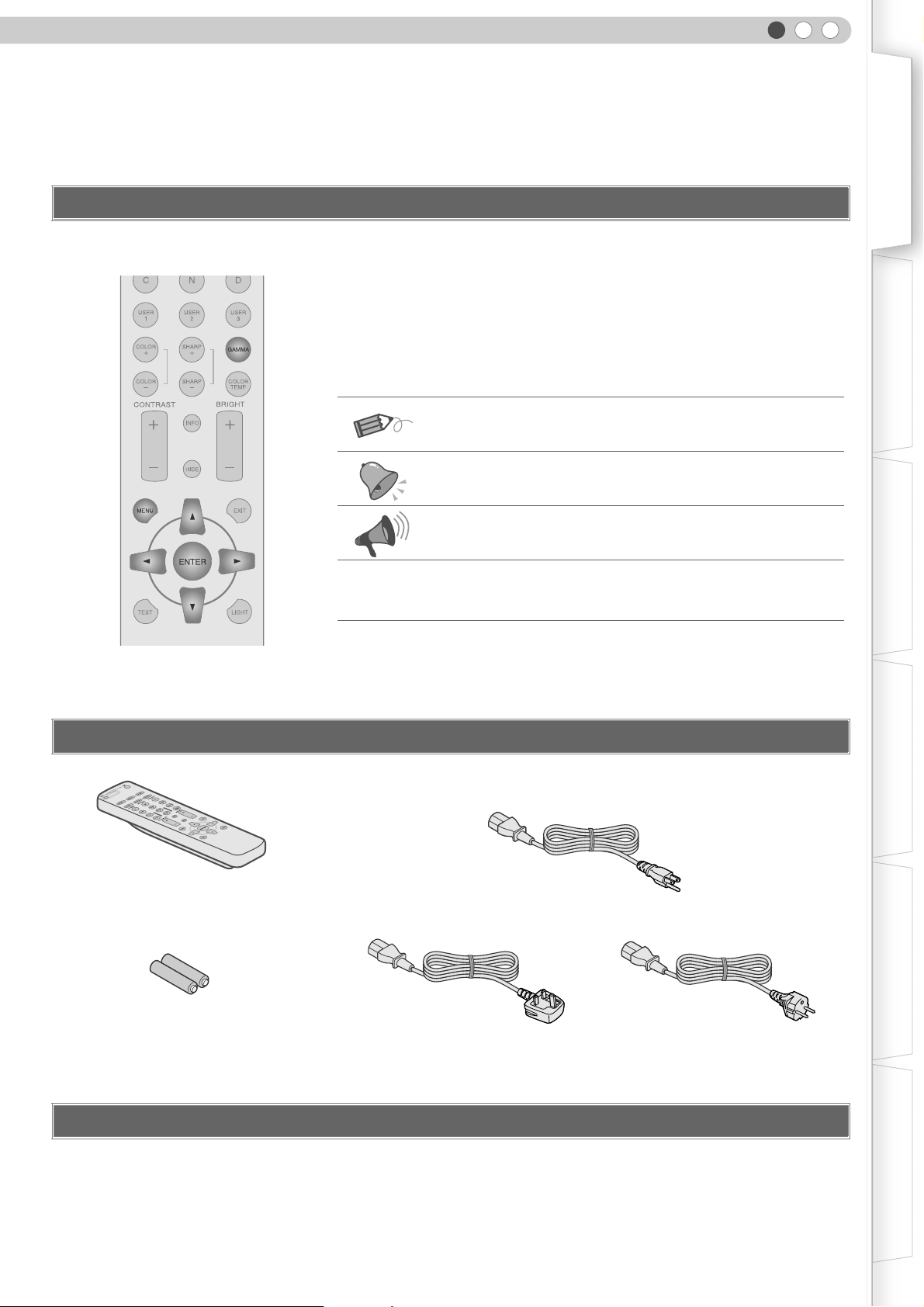
Check the Accessories
Remote Control
Describes operational precautions.
pP13
The power cord supplied varies depending on the destination.
For the US market (x 1):
For the EU market (x 2):
Indicates related pages.
Power Cord
For USA (2.4m)
AAA size Batteries
(for operation confirmation)
z Instruction manual, warranty card and other printed material are also included.
Power Cord
For UK (2m)
Optional Accessories
Please check with your authorized dealer for details.
Replacement Lamp: BHL5009-S (Lamp Unit)
z
z Replacement Filter: LC32058-002A (Inner Filter)
Power Cord
For European continent countries (2m)
13
Page 14
1
Getting Started
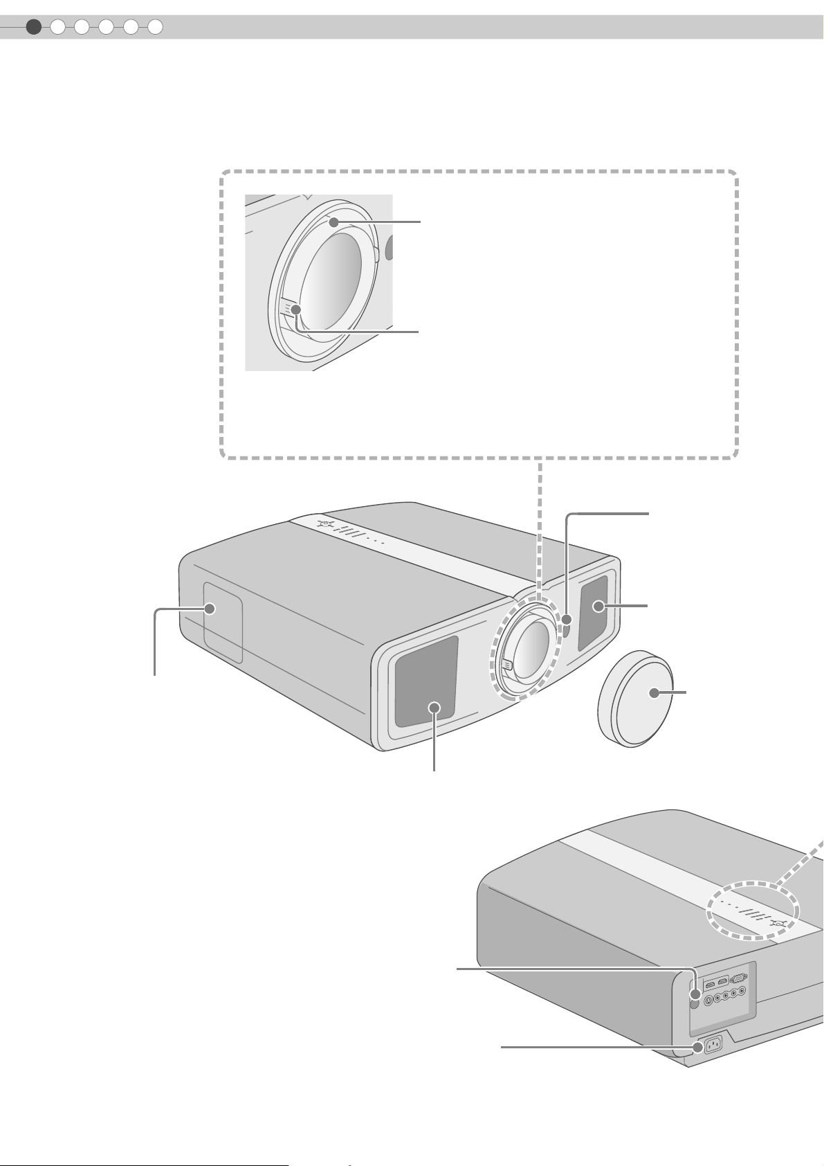
Controls and Features
z This unit comes with buffer material that cushions the lens. Remove the buffer
material before use.
z Do not throw away the buffer material, retain for future use. (pP50)
To adjust the focus
(pP25)
To adjust the size of the image
(pP25)
Front Side/Left Side
Lamp Cover (pP42)
Remote Sensor
(pP17)
Air inlets
Lens Cap
Exhaust Vent
Rear Side/Top Surface
14
Remote Sensor (pP17)
To connect the power cord (pP24)
Page 15
ENGLISH
Getting Started Preparation Basic Operation Settings Troubleshooting Others
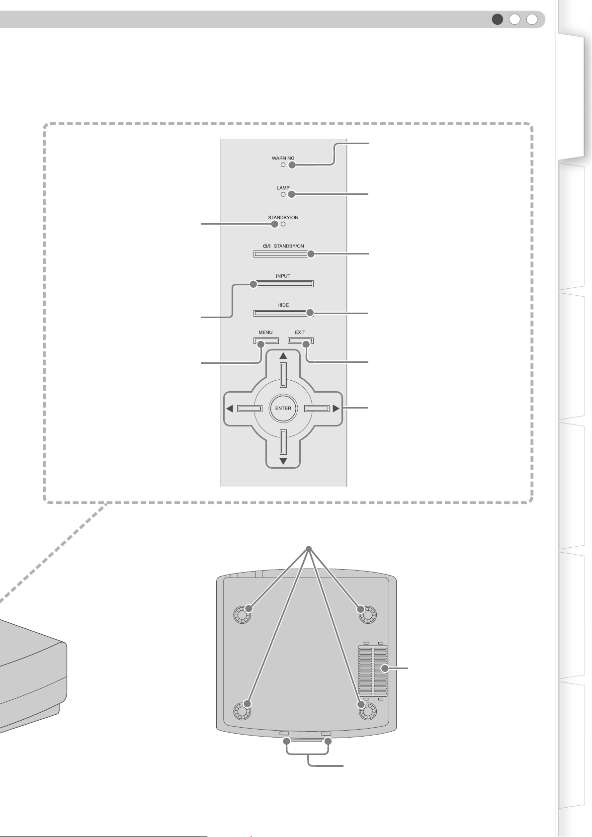
Light on (Red):
Standby mode
Light on (Green):
During projection
Blinking (Green):
Image is temporarily hidden
(pP25)
Blinking (Red):
Cool Down mode (pP25)
To switch input
(pP24)
To display the menu
(pP28)
Light on (Red):
Warning mode (pP41)
Light on/Blinking (Orange):
Lamp warning (pP41)
To turn on/off the power
To hide the image temporarily (pP25)
To return to the previous menu
To select or confirm
Bottom Surface
Feet:
The height (0 - 5 mm) can be adjusted by turning the foot.
Air Inlets/Filter (pP45)
To adjust the position of the image (pP23)
15
Page 16
1
Getting Started
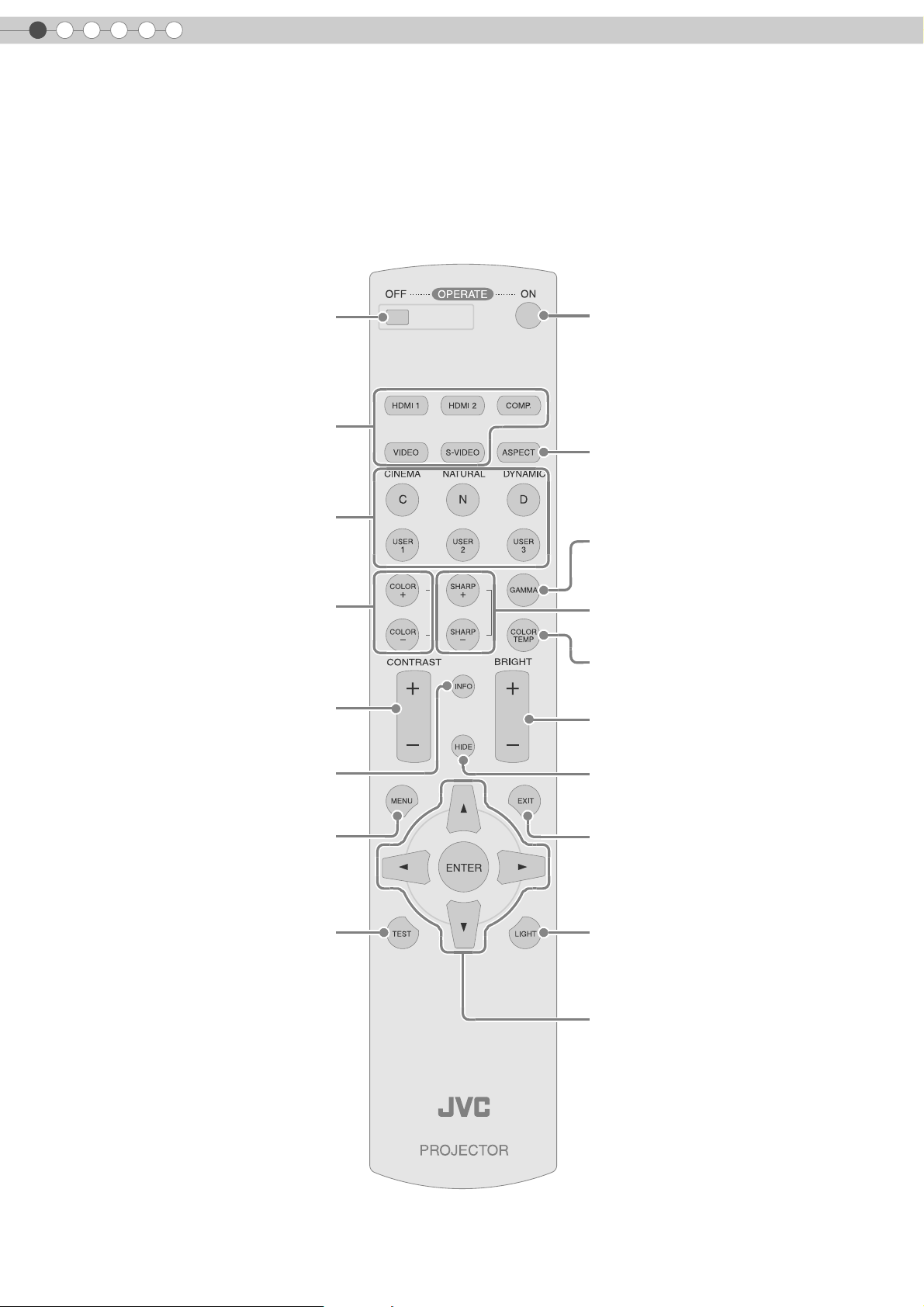
Controls and Features (Continued)
Remote Control
To turn off the power
Select input mode (pP24)
To switch image profile
(pP36)
To adjust color density
(pP36)
To adjust contrast
(pP36)
To turn on the power
To set screen size
(pP26)
To set gamma
(pP36)
To adjust the outline of the image
(pP36)
To set color temperature
(pP36)
To adjust brightness
(pP36)
To display information
To display the menu
(pP28)
To display test patterns
To hide the image temporarily
(pP25)
To return to the previous menu
To illuminate buttons on the remote control
To select or confirm
16
Page 17

ENGLISH
How to Use the Remote Control
Loading Batteries
z If the remote control has to be brought closer to the projector to operate, it means that the batteries are wearing out. When this
happens, replace the batteries. Insert the batteries according to the +- marks.
z Be sure to insert the - end first.
z If an error occurs when using the remote control, remove the batteries and wait for 5 minutes. Load the batteries again and
operate the remote control.
The following instruction applies only to the use in Holland.
Getting Started Preparation Basic Operation Settings Troubleshooting Others
Effective Range of Remote Control Unit
When directing the remote control
toward this unit
When aiming the remote control towards the
z
remote sensor on this unit, ensure that the
distance to the sensor in front or at the rear of
this unit is within 7 m.
z If the remote control fails to work properly,
move closer to this unit.
When reflecting off a screen
Ensure that total of distance A between this
z
unit and screen and distance B between
remote control and screen is within 7 m.
z As the efficiency of signals reflected from the
remote control unit differ with the type of
screen used, operable distance may
decrease.
This unit
Remote Control
This unit
Screen
Remote Control
17
Page 18

2
Preparation
Selecting Connecting Devices
z Do not turn on the power until connection is complete.
z The connection procedures differ according to the device used. For details, refer to the instruction manual of the device to be
connected.
z For audio output, connect the device to an amplifier.
z The images may not be displayed depending on the devices and cables to be connected.
z It may not be possible to connect to this unit depending on the dimension of the connector cover of the cables to be
connected.
DVD Recorder DVD Player
To connect via HDMI terminal (pP20)
To connect RS-232C terminal (for servicing)
To connect via component video terminals (pP20)
To connect via video terminal (pP19)
To connect via S-video terminal (pP19)
18
Camcorder VCR
Page 19

Connecting
Connecting via Video Cable
This unit
ENGLISH
Getting Started Preparation Basic Operation Settings Troubleshooting Others
VCR and camcorder
Video cable (sold separately)
To video input terminal
Connecting via S-video Cable
This unit
Video output
VCR and camcorder
To S-video input terminal
S-video cable (sold separately)
S-video output
19
Page 20

2
Preparation
Connecting (Continued)
Connecting via HDMI Cable Or HDMI-DVI Conversion Cable
PC
This unit
HDMI-DVI conversion cable (sold separately)
DVI output terminal
DVD recorder
HDMI output terminal
HDMI cable (sold separately)
To HDMI 1 or HDMI 2 input terminal
z
The HDMI terminals accept PC format of 1920 c 1080 at 60 Hz, 640 c 480 at 60 Hz and 640 c 480 at 59.94 Hz.
Connecting via Component Video Cable
This unit
DVD player
Component video output terminals
20
Component video cable
(sold separately)
To component video input terminals
z Set ACOMPB in the setting menu to AY Pb/Cb Pr/CrB. (pP31 - P)
C
(Red)
R/PR
CB/PB(Blue)
Y (Green)
Page 21

Connecting via SCART-RCA Cable
This unit
SCART-RCA cable
(sold separately)
ENGLISH
Getting Started Preparation Basic Operation Settings Troubleshooting Others
DVD player for European market
To RGB video and sync signal input terminals
z Set ACOMPB in the setting menu to ASCARTB. (pP31 - P)
Connecting via RGB Video Cable
This unit
SCART terminal
Device equipped with RGB output
RGB video cable
(sold separately)
To RGB video input terminals
z Set ACOMPB in the setting menu to ARGBB. (pP31 - P)
z For information on compatible input signals, see ASpecificationsB. (pP52)
RGB video output terminals
R (Red)
B (Blue)
G (Green) (Includes sync signal)
21
Page 22

2
Preparation
Installing the Projector and Screen
Install this unit and the screen. Place this unit and the screen perpendicular to each other.
Failing to do so may give rise to trapezoidal distortion of the projected image.
A Install the projector and screen
Left/Right position
*0 % up/down position (center)
Approximately 34 % (maximum) of the projected image
(Turn the dial to the right for maximum)
Approximately 34 % (maximum) of the projected image
(Turn the dial to the left for maximum)
Up/Down position
*0 % left/right position (center)
Approximately 80 % (maximum) of the projected image
(Turn the dial to the left for maximum)
Approximately 80 % (maximum) of the projected image
(Turn the dial to the right for maximum)
22
Shifting range of projected image
Page 23

ENGLISH
B Adjust such that the projected image is in the center of the screen
Getting Started Preparation Basic Operation Settings Troubleshooting Others
Moves the image to the
left or right
Moves the image up or
down
z It may be necessary to set APixel AdjustB in the setting menu after adjusting the image position. (pP30 - J)
Screen Size and Projection Distance
Determine the distance from the lens to the screen to achieve your desired screen size.
This unit uses a 2.0x manual zoom lens for projection.
Relationship Between Projection Screen Size and Projection Distance
Projection Screen
Size
(Diagonal Length)
Aspect Ratio 16:9
60"
(Approx. 152.4 cm)
Approximate Projection Distance
W (Wide) f T (Tele)
Approx.
1.78 m
f
Approx.
3.63 m
Projection Screen
Size
(Diagonal Length)
Aspect Ratio 16:9
140"
(Approx. 355.6 cm)
Approximate Projection Distance
W (Wide) f T (Tele)
Approx.
4.24 m
f
Approx.
8.54 m
70"
(Approx. 177.8 cm)
80"
(Approx. 203.2 cm)
90"
(Approx. 228.6 cm)
100"
(Approx. 254.0 cm)
110"
(Approx. 279.4 cm)
120"
(Approx. 304.8 cm)
130"
(Approx. 330.2 cm)
z
The projection distances in the table are provided only as a guide. Use them as a reference during installation.
Approx.
2.09 m
Approx.
2.40 m
Approx.
2.71 m
Approx.
3.01 m
Approx.
3.32 m
Approx.
3.63 m
Approx.
3.93 m
f
f
f
f
f
f
f
Approx.
4.24 m
Approx.
4.86 m
Approx.
5.47 m
Approx.
6.08 m
Approx.
6.70 m
Approx.
7.31 m
Approx.
7.93 m
150"
(Approx. 381.0 cm)
160"
(Approx. 406.4 cm)
170"
(Approx. 431.8 cm)
180"
(Approx. 457.2 cm)
190"
(Approx. 482.6 cm)
200"
(Approx. 508.0 cm)
Approx.
4.55 m
Approx.
4.86 m
Approx.
5.16 m
Approx.
5.47 m
Approx.
5.78 m
Approx.
6.08 m
z To adjust the installation, use a projected image of aspect ratio 16:9.
f
f
f
f
f
f
Approx.
9.16 m
Approx.
9.77 m
Approx.
10.38 m
Approx.
11.00 m
Approx.
11.61 m
Approx.
12.23 m
23
Page 24

3
Basic Operation
Projecting Image
This section describes the basic operations to project input images on the screen.
Preparation
z Remove the lens cap.
A Insert the power plug to the power outlet
A Connect to this unit
B Connect to the power outlet
Power Cord
(Supplied)
B Turn on the power
z You can also press the [STANDBY/ON] button on the unit to turn on the
power. (pP15)
C Project the image
a Select input mode
Light on (Red)
Light on (Green)
24
z You can also select the input mode by pressing the [INPUT] button on
the unit. (pP15)
b Play back the selected device
D Adjust the position of the projection screen
z See AInstalling the Projector and ScreenB for procedures on adjusting the
position. (pP22)
Page 25

E Adjust the image size (zoom)
ENGLISH
Getting Started
TIPS
Bigger
Hold and rotate the tab
F Adjust the focus
Turn the ring and adjust
G Turn off the power
While a confirmation screen is displayed
Smaller
You can hide the image
temporarily
You can hide the image temporarily.
Preparation Basic Operation Settings Troubleshooting Others
Green light blinks when
the image is hidden
z Press the [HIDE] button again to
display image.
z The power cannot be turned off
when the image is temporarily
hidden.
MEMO
About Cool Down mode
Blinking (Red)
Cool Down mode
Light on (Red)
z The power cannot be turned off within approximately 90 seconds after it
has been turned on. Start operation only after 90 seconds time.
z You can also press the [STANDBY/ON] button on the unit to turn off the
power. (pP15)
z Put back the lens cap after use to prevent the lens from dirt.
z Pull out the power plug when the unit will not be used for a prolonged time.
z
The Cool Down mode is a function
to cool down the lamp for
approximately 60 seconds after
projection is complete.
This function prevents the internal
parts of the unit from deformation
or damage due to overheating of
the lamp. It also prevents lamp
blowout and premature shortening
of lamp life.
z During Cool Down mode, the
[STANDBY/ON] indicator blinks in
red.
z After the Cool Down mode is
complete, the unit automatically
returns to standby mode.
z Do not pull out the power plug
during Cool Down mode. This may
shorten the lamp life and cause a
malfunction.
25
Page 26

3
Basic Operation
Convenient Features during Projection
You can change the screen size of the projected image or hide the surrounding area of an image for which
quality at the outer area has deteriorated.
Setting the Screen Size
The projected image can be set to a most appropriate screen size (aspect
ratio).
z
The screen size can also be set from AAspectB of the setting menu. (pP32 - R)
z When high definition images are input, the screen size is fixed at A16:9B.
Input Image and Projected Image by Different Screen Size Settings
Input Image
SDTV(4:3)
SDTV(4:3)
Image recorded in
landscape (black
bands on top and
bottom) of DVD
software
Depending on the input image, selecting A4:3B may result in a vertically stretched
z
image while selecting A16:9B provides you with the most appropriate screen size.
Aspect Ratio: Same
Most appropriate
screen size
Aspect Ratio: Same
Small image is
projected
4:3 16:9 Zoom
Screen Size
Aspect Ratio:
Landscape
Image is stretched
horizontally
Aspect Ratio:
Landscape
Image is stretched
horizontally
Aspect Ratio: Same
Top and bottom of the
image are missing
Aspect Ratio: Same
Most appropriate
screen size
26
Masking the Surrounding Area of an Image
Images for which quality at the outer area has deteriorated can be projected
by masking (hiding) the surrounding area of the projected image.
A Project the image
iImage for which quality at the outer
area has deteriorated.
Page 27

B Mask the image
ENGLISH
Getting Started
a Display the setting menu
b Select ASetupB g AMaskB
ASELECT
BCONFIRM
c Set a mask value
ASELECT
BCONFIRM
Setup
Image
Image Adjust
Color Temp.
Gamma
Offset
Pixel Adjust
Image Profile
Profile Memory
Picture Position
HDMI Input Level
Mask
Image Profile
Profile Memory
Picture Position
HDMI Input Level
Mask
Video Install. Func. Info.
SetupImage Video Install. Func. Info.
2.5%
5%
Off
SetupImage Video Install. Func. Info.
2.5%
5%
Off
MEMO
z Masking is available only when high
definition images are input.
Preparation Basic Operation Settings Troubleshooting Others
Example:
When the AMaskB value is changed
from AOffB g A5%B
C To end
27
Page 28

4
Settings
Setting Menu
Projected images can be adjusted to a desired view by changing the default settings.
Procedures for Menu Operation
Example:
When AAspectB is changed from A4:3B to A16:9B
A Display the setting menu
Image
Image Adjust
Color Temp.
Gamma
Offset
Pixel Adjust
Setup
Video Install. Func. Info.
B Select “Video” g “Aspect”
ASELECT
BCONFIRM
Image
COMP
HDMI
Aspect
Film Mode
Color System
Black Level
C Set to “16:9”
ASELECT
BCONFIRM
Image
COMP
HDMI
Aspect
Film Mode
Color System
Black Level
D To end
Setup
Video Install. Func. Info.
4:3
16:9
Zoom
Setup
Video Install. Func. Info.
4:3
16:9
Zoom
28
Page 29

Setting Menu
Item values shown in are factory settings.
z Items that can be configured differ according to the input signals.
Image>Image Adjust
A Contrast
Adjusts the contrast of the projected image.
(Black) b30 f 30 (White)
B Brightness
Adjusts the brightness of the projected image.
(Darken) b30 f 30 (Brighten)
C Color
Adjusts the color density of the projected image.
(Lighten) b30 f 30 (Darken)
D Tint
Adjusts the hue of the projected image.
(Red) b30 f 30 (Green)
E Sharpness
Adjusts the outline of the projected image.
(Soft) b30 f 30 (Sharp)
F DNR
Adjusts the strength of noise removal of the projected image.
(Weak) 0 f 30 (Strong)
ENGLISH
Getting Started
Preparation Basic Operation Settings Troubleshooting Others
z AContrastB, ABrightnessB, AColorB and ASharpnessB can also be configured from the remote control. (pP16)
z ATintB can only be adjusted when NTSC signals are input to the video or S-video input terminal.
Image>Color Temp.
G Color Temp.
Sets the color temperature of the projected image.
Low Select this to give a reddish tinge to the image.
Middle Select this to have a balanced image.
High Select this to give a bluish tinge to the image.
Red (Less red) b255 f 0 (More red)
User10
User20
* The red, green and blue colors can be adjusted and registered respectively.
Green (Less green) b255 f 0 (More green)
Blue (Less blue) b255 f 0 (More blue)
Red (Less red) b255 f 0 (More red)
Green (Less green) b255 f 0 (More green)
Blue (Less blue) b255 f 0 (More blue)
z This setting can also be configured from the remote control. (pP16)
29
Page 30

4
Settings
Setting Menu (Continued)
Image>Gamma
H Gamma
Sets the gradation characteristics of the projected image.
Normal For normal circumstances, select this setting.
A Sets gamma to AAB.
B Sets gamma to ABB.
C Sets gamma to ACB.
ANormalB is suitable for normal circumstances but AAB, ABB or ACB can be selected according to your preference.
z
z This setting can also be configured from the remote control. (pP16)
Image>Offset
I Offset
Adjusts the respective brightness of the red, green and blue colors. (Offset level)
Red (Less red) b30 f 30 (More red)
Green (Less green) b30 f 30 (More green)
Blue (Less blue) b30 f 30 (More blue)
Image>Pixel Adjust
J Pixel Adjust
Makes fine adjustments of 1 pixel unit to the red, green and blue colors respectively in the horizontal/vertical direction of the
image.
Horiz. Red (Moves red to left) 1 f 7 (Moves red to right)
Horiz. Green (Moves green to left) 1 f 7 (Moves green to right)
Horiz. Blue (Moves blue to left) 1 f 7 (Moves blue to right)
Vert. Red (Moves red down) 1 f 5 (Moves red up)
Vert. Green (Moves green down) 1 f 5 (Moves green up)
Vert. Blue (Moves blue down) 1 f 5 (Moves blue up)
z The horizontal and vertical directions are reversed when the image is flipped to the left or right, or flipped up or down.
z To adjust, use still images with distinct outlines.
z As the adjustments are minor, the effect may be difficult to see for some images.
Setup>Image Profile
K Image Profile
Configures the image profile. (pP36)
Cinema Select this to view images with movie quality in a dark room.
Natural Select this to view projected images with quality as-is in a dark room.
Dynamic Select this to view images with clear quality in a bright room.
User1 Selects image profile registered in AUser1B.
User2 Selects image profile registered in AUser2B.
User3 Selects image profile registered in AUser3B.
30
z This setting can also be configured from the remote control. (pP16)
Page 31

ENGLISH
Setup>Profile Memory
L Profile Memory
Registers or deletes image profiles.
Save User1 Registers image profile in AUser1B.
Save User2 Registers image profile in AUser2B.
Save User3 Registers image profile in AUser3B.
Clear User1 Returns image profile in AUser1B to factory setting (natural).
Clear User2 Returns image profile in AUser2B to factory setting (natural).
Clear User3 Returns image profile in AUser3B to factory setting (natural).
Reset Cinema Returns image profile in ACinemaB to factory setting.
Reset Natural Returns image profile in ANaturalB to factory setting.
Reset Dynamic Returns image profile in ADynamicB to factory setting.
z AContrastB, ABrightnessB, AColorB, ASharpnessB, ADNRB, AColor Temp.B, AGammaB and AOffsetB are registered in AImage
ProfileB.
Getting Started
Preparation Basic Operation Settings Troubleshooting Others
Setup>Picture Position
M Picture Position
Adjusts the horizontal/vertical position of the projected image.
z The display position value varies with the input signal.
z This adjustment is available only for analog input signals.
Setup>HDMI Input Level
N HDMI Input Level
Configures the input level setting of the HDMI input terminal.
Standard For normal circumstances, select this setting.
Enhanced
Select this setting when the black-and-white of the projected image is unclear when
RGB video signals are input from DVI devices.
z This setting is available only when projecting the HDMI input.
Setup>Mask
O Mask
Masks (Hides) the outer area of the projected image.
2.5% Masks 2.5 % of the screen.
5% Masks 5 % of the screen.
Off No masking.
z Masking is available only when high definition images are input.
Video>COMP
P COMP
Configures the input signals of the component video input terminals.
Y Pb/Cb Pr/Cr Select this when component video signals are input.
RGB Select this when RGB video signals are input.
SCART
Select this when RGB video signals and sync signals are input from SCART plug for
European market.
z This setting is available only when projecting the component video input.
31
Page 32

4
Settings
Setting Menu (Continued)
Video>HDMI
Q HDMI
Configures the input signals of the HDMI input terminal.
Auto Automatically configures input signals.
YCbCr(4:4:4) Select this when Y Cb Cr (4:4:4) video signals are input.
YCbCr(4:2:2) Select this when Y Cb Cr (4:2:2) video signals are input.
RGB Select this when RGB video signals are input.
This setting is available only when projecting the HDMI input.
z
Video>Aspect
R Aspect
Configures the screen size (aspect ratio) of the projected image.
4:3 Sets screen size of the projected image to 4:3.
16:9 Sets screen size of the projected image to 16:9.
Zoom Zooms the image.
z When high definition images are input, the screen size is fixed at A16:9B.
z This setting can also be configured from the remote control. (pP16, 26)
Video>Film Mode
S Film Mode
Select this to view movies shot on film.
Auto For normal circumstances, select this setting.
Off Select this when you are not watching movies shot on film.
Video>Color System
T Color System
Configures the color system.
Auto Configures the color system automatically.
NTSC Select this when the color system is NTSC.
NTSC4.43 Select this when the color system is NTSC4.43.
PAL Select this when the color system is PAL.
PAL-M Select this when the color system is PAL-M.
PAL-N Select this when the color system is PAL-N.
SECAM Select this when the color system is SECAM.
32
z This setting is available only when projecting the video or S-video input.
Video>Black Level
U Black Level
Configures the black level.
0 %
7.5 % Select this when the dark portions of an image appears washed out with the 0 % setting.
Select this when the gradation of the dark portions of an image is indistinct with the
7.5 % setting.
z This setting can only be adjusted when NTSC signals are input to the video or S-video input terminal.
Page 33

Install.>Menu Position
V Menu Position
Sets the display position of the menu.
Upper left Displays menu on the upper left of the screen.
Upper center Displays menu on the upper center of the screen.
Upper right Displays menu on the upper right of the screen.
Left center Displays menu on the left center of the screen.
Center Displays menu on the center of the screen.
Right center Displays menu on the right center of the screen.
Lower left Displays menu on the lower left of the screen.
Lower center Displays menu on the lower center of the screen.
Lower right Displays menu on the lower right of the screen.
ENGLISH
Getting Started
Preparation Basic Operation Settings Troubleshooting Others
Install.>Menu Display
W Menu Display
Sets the duration for displaying the menu.
15 sec Displays for 15 seconds.
On Always display.
Install.>Line Display
X Line Display
Sets whether to display the input when switching input.
5 sec Displays for 5 seconds.
Off Do not display.
Install.>Flip H
Y Flip H
Select this when the image is projected from the back of the screen or when the projector is hung from the ceiling.
On Flips image to the left or right.
Off Do not flip image to the left or right.
Install.>Flip V
Z Flip V
Select this when the projector is hung from the ceiling.
On Flips image up or down.
Off Do not flip image up or down.
33
Page 34

4
Settings
Setting Menu (Continued)
Install.>High Altitude Mode
a High Altitude Mode
Select this when using the projector in a location of low atmospheric pressure (higher than 900 meters above sea level).
On Activate.
Off Do not activate.
Func.>Back Color
b Back Color
Configures the screen color displayed when there is no input signal.
Blue Sets screen color to ABlueB.
Black Sets screen color to ABlackB.
Func.>Sleep Timer
c Sleep Timer
Sets the lapse time before automatically switching to the standby mode when there is no input signal.
15 Switch to standby mode after 15 minutes.
30 Switch to standby mode after 30 minutes.
60 Switch to standby mode after 60 minutes.
Off Do not switch to standby mode.
Func.>D-ILA Logo
d D-ILA Logo
Sets whether to display AD-ILA LogoB during startup.
On Displays for 5 seconds.
Off Do not display.
Func.>Lamp Power
e Lamp Power
Configures the output of the light-source lamp.
Normal For normal circumstances, select this setting. (170 W)
High Select this when it is difficult to see the image in a bright room. (200 W)
Changing the lamp power will not change the lamp time (lamp life).
z
z The setting cannot be changed within approximately 90 seconds after this unit has been turned on.
z Settings cannot be changed within approximately 60 seconds after they are made.
Func.>Test Pattern
f Test Pattern
Displays 6 types of test patterns.
34
z This can also be displayed from the remote control. (pP16)
Page 35

Func.>Language
g Language
Sets the language of the menu display.
日本語 Japanese
English English
Deutsch German
Español Spanish
Italiano Italian
Français French
Português Portuguese
Nederlands Dutch
Svenska Swedish
Norsk Norwegian
中文 Chinese (Simplified)
ENGLISH
Getting Started
Preparation Basic Operation Settings Troubleshooting Others
Info.
h Input
Displays the currently selected video input.
i Source
Displays the types of the current input video signals.
j Lamp Time
Displays the accumulated hours of usage of the light-source lamp.
z This can also be displayed from the remote control. (pP16)
35
Page 36

4
Settings
Customizing Projected Images
You can adjust the projected image to a desired image quality and register the adjusted value. (Image profile)
Besides the default ACinemaB, ANaturalB and ADynamicB settings, there are 3 more types of user-defined
settings for image profile.
Changing the Default Image Profile Values
AContrastB, ABrightnessB, AColorB, ASharpnessB, ADNRB, AColor Temp.B, AGammaB
and AOffsetB are registered in the image profile.
A Select the image profile
B Adjust image quality
Example: To adjust AContrastB
a Select AImageB g AImage AdjustB
ASELECT
BCONFIRM
b Adjust the setting
ASELECT
BCONFIRM
Image
Image Adjust
Color Temp.
Gamma
Offset
Pixel Adjust
Image
Image Adjust
Color Temp.
Gamma
Offset
Pixel Adjust
Setup
Video Install. Func. Info.
Contrast
Brightness
Color
Tint
Sharpness
DNR
Setup
Video Install. Func. Info.
Contrast
Brightness
Color
Tint
Sharpness
DNR
36
Contrast
z AContrastB, ABrightnessB, AColorB, ASharpnessB, AColor Temp.B and
AGammaB can also be adjusted from the remote control. (pP16)
C Other items can also be adjusted
D To end
z To return to the default values, reset the registered settings with AProfile
MemoryB in the setting menu. (pP31 - L)
Page 37

Registering User-defined Image Profiles
ENGLISH
Getting Started
A Select the image profile
B Adjust image quality
z See AChanging the Default Image Profile ValuesB for procedures on
adjusting the image quality. (pP36)
C Register the image profile
a Select ASetupB g AProfile MemoryB
ASELECT
BCONFIRM
Image Profile
Profile Memory
Picture Position
HDMI Input Level
Mask
Image
Setup
Video Install. Func. Info.
Save User1
Save User2
Save User3
Clear User1
Clear User2
Clear User3
Reset Cinema
Reset Natural
Reset Dynamic
CAUTION
z Adjustment settings of image
quality will not be registered if other
image profiles are selected before
registering these settings.
Preparation Basic Operation Settings Troubleshooting Others
b Register the setting
ASELECT
D To end
z To return to the default values, reset the registered settings with AProfile
MemoryB in the setting menu. (pP31 - L)
BCONFIRM
Image
Image Profile
Profile Memory
Picture Position
HDMI Input Level
Mask
Setup
Video Install. Func. Info.
Save User1
Save User2
Save User3
Clear User1
Clear User2
Clear User3
Reset Cinema
Reset Natural
Reset Dynamic
37
Page 38

5
Troubleshooting
Troubleshooting
Before sending the unit to your authorized dealer for repair, check the following points.
The following situations are not malfunctions.
You do not need to worry under the following situations if there is no abnormality on the screen.
z Part of the top surface or front of the unit is hot.
z A creaking sound is heard from the unit.
z An operating sound is heard from the internal of the unit.
Perform the following operations when the unit is unable to operate normally due to external static or noises.
A When the unit is in standby mode, pull out the power plug, then insert again.
B Press the power button on the unit to turn on the power again.
A sound may be heard when the lamp is off but there is no danger.
D-ILA device is manufactured using high-precision technology but there may be some missing pixels or pixels that remain
permanently lit up.
Power is not supplied
Is the power cord disconnected? Insert the power cord (plug) firmly. pP24
Remove the power plug when the unit is in standby mode and
Is the lamp cover properly shut?
Is the lamp in Cool Down mode?
close the lamp cover properly. After that, insert the plug
again.
After the Cool Down mode is complete, turn on the power
again.
pP43
pP25
Projected image is dark
Check the lamp time on the information menu. Prepare a new
Is the lamp near exhaustion?
lamp unit or replace as soon as possible when the lamp is near
exhaustion.
pP42f44
The unit works when power is turned on but stops abruptly after a few minutes
Are the air inlets and exhaust vent
blocked?
Is the filter dirty? Clean the filter. pP45
Remove the power plug when the unit is in standby mode and
remove any blocking object. After that, insert the plug again.
pP3, 14
Video image does not appear
Is the lens cap removed? Remove the lens cap. pP24
Is the correct external input selected? Select the correct external input. pP24
Is the AV device properly connected? Connect the AV device properly. pP18f20
38
Is the power of the AV device turned on? Turn on the power of the AV device and play the video. pP24
Are the correct signals being output from
the AV device?
Is the setting of the input terminal correct?
Is the video image temporarily hidden? Press the [HIDE] button to display the video image again. pP25
Set the AV device properly. pP18f20
Set ACOMPB and AHDMIB in the setting menu according to the
input signal.
pP31 - P
pP32 - Q
Color does not appear or looks strange
Is the image correctly adjusted? Adjust AColorB and ATintB in the setting menu. pP29 - CD
Page 39

ENGLISH
Video image is fuzzy
Is the focus correctly adjusted? Adjust accordingly using the focus adjustment ring. pP25
Getting Started Preparation Basic Operation Settings Troubleshooting Others
Is the unit placed too near or too far away
from the screen?
Set the unit at a correct distance from the screen. pP22, 23
Video images are missing
Has setting been performed for screen
mask?
Is the display out of position?
Set the AMaskB in the setting menu to AOffB. pP27, 31 - O
Alter the APicture PositionB value in the setting menu to ensure
that images are not missing.
pP31 - M
Remote control does not work
Are batteries installed correctly?
Are batteries exhausted? Replace with new batteries. pP17
Is there an obstructive object between the
remote control and remote sensor?
Is the remote control held too far away
from the unit?
Match the polarities (+ or -) correctly when inserting the
batteries.
Remove any obstructive objects. pP17
Hold the remote control closer to the sensor when using. pP17
pP17
Power is cut off suddenly
Has setting been performed for sleep
time?
Set the ASleep TimerB in the setting menu to AOffB. pP34 - c
39
Page 40

5
Troubleshooting
What to Do When These Messages Are Displayed
Message Cause (Details)
COMP
No input
HDMI-2
Frequency of input signal is out of range.
Lamp replacement
Lamp replacement
Warning
EXIT
EXIT
No device is connected to the input terminal.
The input terminal is connected but there is no signal.
gInput the video signals.
A video signal that cannot be used in this unit has been input.
gInput video signals that can be used.
The message is displayed when the accumulated lamp time has exceeded
1900 hours.
To clear the message, press the [EXIT] button.
gGet ready a new lamp unit and replace as soon as possible.
The message is displayed when the accumulated lamp time has exceeded
2000 hours.
The message is displayed each time during projection.
To clear the message, press the [EXIT] button.
gReplace with a new lamp unit and reset the lamp time. (pP42f44)
40
Page 41

ENGLISH
About Warning Indicators
The accumulated lamp time or warning mode of this unit is displayed by the indicators.
For information on indicator display during normal operation, see AControls and FeaturesB (pP14).
Getting Started Preparation Basic Operation Settings Troubleshooting Others
No.
STANDBY/ON LAMP WARNING
1
b Light on b
2
3
4 Lamp is turned off during projection
5 Lamp cover is removed
6
7
8
9
10
b Blinking Light on
bbLight on
Indicator
Content
Lamp replacement is near (pP42 f 44)
(When accumulated lamp time has exceeded 1900 hours)
Lamp has reached end of life (pP42 f 44)
(When accumulated lamp time has exceeded 2000 hours)
Lamp does not light up and unit is unable to project
There is an error in the circuit operation
(Operation error in microcomputer circuit)
There is an error in the circuit operation
(Operation error in drive circuit)
Internal temperature is abnormally high
(Internal temperature error)
External temperature is high
(External temperature error)
Cooling fan has stopped
(Fan locked)
Actions to Be Taken for Warning Mode
When the unit enters into warning mode (No. 3 to 10), it will automatically stop projection and run the cooling fan for
about 60 seconds.
After the cooling fan has stopped, pull out the power plug from the power outlet.
Then, follow the procedures below.
No. Check Action
3
4
5
6
7
8
9
10
If the warning indication is displayed again, wait for the cooling fan to stop. Then pull out the power plug from the power outlet.
Call your authorized dealer for repair.
z Check that an impact shock has not occurred during
operation.
z Check that the lamp unit and lamp cover are correctly
installed.
z Check that nothing is blocking the air inlets.
z Check that the external temperature is normal.
Turn on the power again.
Leave the unit until it cools down.
After that, turn on the power again.
41
Page 42

5
Troubleshooting
Replacing the Lamp
The lamp is a consumable item. If the image is dark or the lamp is turned off, replace the lamp unit.
When the lamp replacement time approaches, a message is displayed on the screen and the condition is indicated by the
z
indicator. (pP40, 41)
Procedure for Lamp Replacement
CAUTION
z Pull the power plug from the power
outlet. Failure to do so may cause
injuries or electric shocks.
z Do not replace the lamp
immediately after the unit has been
used. Allow a cooling period of 1
hour or more before replacement.
The temperature of the lamp is still
high and this may cause a burn.
z Do not apply shock to the lamp
unit. It may cause lamp blowout.
z Do not use flammable air duster to
clean the internal parts of the unit.
This may cause fire.
MEMO
Usable Lamp Life
z
The usable lamp life for this unit is
approximately 2000 hours. The
usable lamp life of 2000 hours is
merely the average usable life of
lamps and we do not provide any
guarantee for this figure.
z The lamp life may not reach 2000
hours depending on the operating
conditions.
z When the lamp has reached the
end of its usable life, deterioration
progresses rapidly.
z If the image is dark or the color
tone is abnormal, replace the lamp
unit as soon as possible.
Purchasing the Lamp Unit
A Remove the lamp cover
z Remove the screws with a + screwdriver.
B Loosen the screws on the lamp unit
z Loosen the screws with a + screwdriver.
C Pull out the lamp unit
z Grasp the handle and pull out the lamp unit.
42
Please consult your authorized
dealer.
Lamp Unit
Part No. : BHL5009-S
Handle
Page 43

D Install the new lamp unit
E Tighten the screws of the lamp unit
z Fasten the screws with a + screwdriver.
ENGLISH
CAUTION
z Use only genuine replacement
parts for the lamp unit. Also, never
attempt to re-use an old lamp unit.
This may cause a malfunction.
z Do not touch the surface of a new
lamp. This may shorten the lamp
life and cause lamp blowout.
MEMO
After Replacing the Lamp
z
Do not place the removed lamp
unit at locations reachable by
children or near combustible items.
z Dispose used lamp units in the
same way as fluorescent lamps.
Follow your local community rules
for disposal.
Getting Started Preparation Basic Operation Settings Troubleshooting Others
F Attach the lamp cover
z Insert the top part (with 2 claws) of the lamp cover into the unit.
z Fasten the screws with a + screwdriver.
Claws
43
Page 44

5
Troubleshooting
Replacing the Lamp (Continued)
Resetting Lamp Time
After installing a new lamp unit, reset the lamp time.
A Insert the power plug to the power outlet
Light on (Red)
B Reset lamp time
z Press in the order as shown.
Press for 2 seconds or more
z The [LAMP] indicator and [STANDBY/ON] indicator blink alternately for 3
seconds. After that, the unit switches to standby mode.
44
CAUTION
z Reset the lamp time only when you
have replaced the lamp.
z Never reset it when the lamp is still
in use. Otherwise, the approximate
standard for gauging replacement
time may be inaccurate and lamp
blowout may occur.
Page 45

ENGLISH
Cleaning and Replacing the Filter
Clean the filter regularly or air intake efficiency may deteriorate and malfunction may occur.
A Remove the inner filter
CAUTION
Getting Started Preparation Basic Operation Settings Troubleshooting Others
B Clean the filter
Lift up while pushing the claw
z Pull the power plug from the power
outlet.
MEMO
If the filter is damaged or too
dirty to be cleaned
z
Replace with a new filter. A dirty
filter will dirty the internal parts of
the unit and cause shadows on the
video image.
z To purchase a new filter or when
there is dirt in the internal parts,
consult your authorized dealer.
Inner Filter
Part No. : LC32058-002A
z Wash the filter with water and dry it in a shaded area.
z In extremely soiled cases, use of a neutral detergent is recommended.
Put on rubber gloves when using a neutral detergent.
z After washing the filter with water, make sure that it is completely dry before
reinstalling. Otherwise, electric shocks or malfunctions may occur.
z Do not clean the filter with a vacuum cleaner or air duster. The filter is soft
and may be damaged.
C Reinstall the inner filter
Check that the left and right
claws are locked onto the unit
45
Page 46

Others
6
RS-232C Interface
Control of this unit via a computer is possible by connecting the computer to this unit with a RS-232C cross
cable (D-Sub 9 pin).
RS-232C Specifications
This unit
Pin No. Signal Operation Signal Direction
2 RxD Receive data This unit PC
3 TxD Transmit data This unit PC
5 GND Signal ground b
1, 4, 6 b 9N/C bb
z PC refers to the controller such as a personal computer.
Mode Non-synchronous
Character Length 8 bit
Parity None
Start Bit 1
Stop Bit 1
Data Rate 19200 bps
Data Format Binary
Command Format
Start Bit Stop Bit
The command between this unit and the computer consists of AHeaderB, AUnit IDB, ACommandB, ADataB and AEndB.
z
Header (1 byte), Unit ID (2 bytes), Command (2 bytes), Data (n bytes), End (1 byte)
Header
This binary code indicates the start of communication.
Binary code Type Description
21 Operating command PC This unit
3F Reference command PC This unit
40 Response command This unit PC
06 ACK
Unit ID
This code specifies the unit. The binary code is fixed at A8901B.
This unit PC
(When the command is accepted without error, it returns to PC)
46
Page 47

Command and data
Operating command and data (Binary code)
Command Type Data description
0000 Connection check
5057 Power supply
4950 Input
5243 Remote Control
ENGLISH
Getting Started Preparation Basic Operation Settings Troubleshooting Others
Checks whether communication is available between this unit and
the PC during standby.
During standby
31: Turns on the power.
During power on
30: Turns off the power. (Standby mode)
During power on
30: S-VIDEO
31: VIDEO
32: COMP.
36: HDMI 1
37: HDMI 2
Sends the same code as the supplied remote control.
z ARemote control codeB (pP48)
Reference command and data (Binary code)
Command Type Data description
During standby or power on
30: Standby mode
5057 Power supply
4950 Input
31: Power-on mode
32: During Cool Down mode
34: Warning mode
During power on
30: S-VIDEO
31: VIDEO
32: COMP.
36: HDMI 1
37: HDMI 2
End
This code indicates the end of communication. The binary code is fixed at A0AB.
47
Page 48

Others
6
RS-232C Interface (Continued)
Remote control code
z Binary code is sent during communication.
Remote control button
name
J 37 33 30 31 USER1 37 33 36 43
K 37 33 30 32 USER2 37 33 36 44
EXIT 37 33 30 33 USER3 37 33 36 45
OPERATE ON 37 33 30 35 HDMI 1 37 33 37 30
OPERATE OFF 37333036 HDMI 2 37333731
HIDE 37 33 31 44 INFO 37 33 37 34
MENU 37 33 32 45 GAMMA 37 33 37 35
ENTER 37 33 32 46 COLOR TEMP 37 33 37 36
I 37 33 33 34 ASPECT 37 33 37 37
H 37 33 33 36 CONTRAST (a) 37333738
VIDEO 37333442 CONTRAST (b) 37333739
S-VIDEO 37333443 BRIGHT (a) 37333741
COMP. 37333444 BRIGHT (b) 37333742
TEST 37 33 35 39 COLOR (a) 37333743
Binary code
Remote control button
name
Binary code
CINEMA 37 33 36 39 COLOR (b) 37333744
NATURAL 37 33 36 41 SHARP (a) 37333745
DYNAMIC 37333642 SHARP (b) 37333746
48
Page 49

RS-232C Communication Examples
This section shows the communication examples of RS-232C.
Operating command
Type Command Description
Connection check
Power (On)
Power (Off)
Input (COMP.)
Remote Control
(MENU)
PC This unit: 21 89 01 00 00 0A
This unit PC: 06 89 01 00 00 0A
PC This unit: 21 89 01 50 57 31 0A
This unit PC: 06 89 01 50 57 0A
PC This unit: 21 89 01 50 57 30 0A
This unit PC:06890150570A
PC This unit: 21 89 01 49 50 32 0A
This unit PC: 06 89 01 49 50 0A
PC This unit: 21 89 01 52 43 37 33 32 45 0A
This unit PC:06890152430A
ENGLISH
Getting Started Preparation Basic Operation Settings Troubleshooting Others
Checks connection
When power is turned on from standby mode
When power is turned off (standby mode)
from power-on mode
When video input is set to component
When the same operation as pressing the
[MENU] button on the remote control is made
Reference command
Type Command Description
Power (On)
Input (S-VIDEO)
PC This unit: 3F 89 01 50 57 0A
This unit PC:06890150 570A
This unit PC:4089015057310A
PC This unit: 3F 89 01 49 50 0A
This unit PC:06890149500A
This unit PC:4089014950300A
When information on power-on mode is
acquired
When information on S-VIDEO input is
acquired
49
Page 50

Others
6
Copyright and Caution
About Trademarks and Copyright
z HDMI, HDMI logo and high definition multimedia interface
are trademarks or registered trademarks of HDMI
Licensing LCC.
Caution
D-ILA Device Characteristics
Do not project still pictures or pictures that have still
segments for a long period of time. The still parts of the
picture may remain on the screen. This is a characteristic of
D-ILA devices and not a malfunction. The picture will
disappear over time.
When Unit is Unused for a Long Time
Prolonged disuse of the unit may effect an error on the
functions. Turn on the power occasionally and operate the
unit.
Viewing Advice
Looking at the screen continually for a prolonged time will
cause your eyes to get tired. Allow your eyes to rest at
intervals.
Usage Environment
z This product uses Ricoh TrueType fonts manufactured
and sold by Ricoh Co., Ltd.
Maintenance Procedures
Dirt on the cabinet
z Gently clean dirt on the cabinet with a soft cloth. In the
case of heavy soiling, soak a cloth in water, wring dry and
wipe, followed by wiping again with a dry cloth.
Pay attention to the following as the cabinet may
deteriorate in condition or paint may come off.
• Do not wipe with thinner or benzene
• Do not spray volatile chemicals like insecticide
• Do not allow prolonged contact with rubber or plastic
products
Dirt in the air inlets
z Use a vacuum cleaner to suck up the dirt. Otherwise, use
a cloth to wipe off the dirt. If dirt is allowed to accumulate
in the air inlets, the internal temperature cannot be
adjusted and this may cause a malfunction.
Dirt on the lens
z Clean the dirt using commercial blowers or lens cleaning
papers for cleaning glasses and cameras.
Do not use fluid-type cleaning agents. This may lead to
peeling of the surface coating film.
z Avoid direct exposure of screen to direct sunlight and
illumination. Block light using a curtain. Images can be
well projected by darkening the brightness of the room.
z Do not use this unit in rooms with cigarette smoke or oily
smoke. This may cause the unit to malfunction.
Parts Replacement
This unit contains parts (optical part, cooling fan, etc.) that
require replacement to maintain its functioning. The
estimated time for parts replacement varies greatly
depending on the usage and environment. Please consult
your authorized dealer for replacement.
Transporting this Unit
When transporting this unit for repair or during house
moving, attach the buffer material on the top and bottom of
the lens for protection. Failure to do so may subject the lens
to shock causing damage.
Attach the buffer material after adjusting the lens to the
center position.
50
Page 51

ENGLISH
Mounting this Unit
Measures to prevent the unit from toppling or dropping should be taken for safety reasons and accident prevention
during emergencies including earthquakes.
When mounting this unit on a pedestal or ceiling, remove the 4 feet on the bottom surface and use all the 4 screw
holes (M5 screws) to mount.
Ceiling
Bottom Surface
4 locations
Getting Started Preparation Basic Operation Settings Troubleshooting Others
Precautions for Mounting
z Special expertise and techniques are required for
mounting this unit. Be sure to ask your dealer or a
specialist to perform mounting.
z Depth of the screw holes (screw length) is 30 mm. Use
screws shorter than 30 mm but longer than 19 mm.
z When mounting to a pedestal, ensure sufficient space
(foot height of 21.5 mm or higher) around the unit so that
the air inlets are not blocked.
Air inlets
z Regardless whether the unit is still under guarantee, JVC
is not liable for any product damage caused by mounting
the unit with non-JVC ceiling fittings or when the
environment is not suitable for ceiling-mount.
z When using the unit hanging from a ceiling, pay attention
to the surrounding temperature. When a heater is in use,
temperature around the ceiling is higher than expected.
51
Page 52

Others
6
Specifications
Product Name D-ILA Projector
Model Name DLA-HD1
Display Panel/Size
Projection Lens 2.0x manual zoom lens (1.4: 1 f 2.8: 1) (Zoom/Focus: Manual)
Light-source Lamp 200 W Ultra-high pressure mercury lamp [Part No.: BHL5009-S]
Screen Size Approx. 60" f 200" (Aspect ratio: 16:9)
Projection Distance Approx. 1.8 m f 12.2 m
Color System NTSC, NTSC4.43, PAL, PAL-M, PAL-N, SECAM (Auto/Manual switch)
Analog Video Input Format 480i, 480p, 576i, 576p, 720p/50 Hz, 720p/60 Hz, 1080i/50 Hz, 1080i/60 Hz
Digital Video Input Format
Resolution 1920 dots c 1080 dots
Input Terminals
D-ILA device 1 2 /
0.7" (1920 pixels c1080 pixels) c 3 (Total no. of pixels: Approx. 6.22 million)
480i, 480p, 576i, 576p, 720p/50 Hz, 720p/60 Hz, 1080i/50 Hz, 1080i/60 Hz,
1080p/24 Hz, 1080p/50 Hz, 1080p/60 Hz, VGA 60Hz
Video Input
(VIDEO)
S-video Input
(S-VIDEO)
Component Video Input
(COMPONENT)
HDMI Input
(HDMI 1, HDMI 2)
Power Requirements AC 110 V - 240 V 50/60 Hz
Power Consumption 280 W (Standby mode: 2.7 W)
Operation Environment
Installation Height Below 5000 ft (Approx. 1524 m)
Dimensions (Width c Height c Depth)
Mass 11.6 kg (25.5 lbs)
Accessories (See Page 13)
1-line, RCA pin jack c 1
1.0 V(p-p), 75 &, synchronous
1-line, mini DIN 4 pin c 1
Y: 1.0 V(p-p), 75 &
C: 0.286 V(p-p), 75 & (NTSC); 0.3 V(p-p), 75 & (PAL)
1-line, RCA pin jack c 3
Y: 1.0 V(p-p), 75 &
, CR/PR: 0.7 V(p-p), 75 &
C
B/PB
2-line, HDMI 19 pin c 2 (HDCP compliant) 3
Temperature: 5 %f35 %
Humidity: 20 % f 80 % (No condensation)
(Storage Temperature: b10 %f60 %)
455 mm c 172.5 mm c 418.5 mm
(17 7/8" c 6 7/8" c 16 1/2")
(Excluding lens and protrusion portion)
52
1 D-ILA is the abbreviation for Direct drive Image Light Amplifer.
2 D-ILA devices are manufactured using extremely high-precision technology. Pixel effectiveness is 99.99 %. Only 0.01 % or less of the pixels
are either missing or would remain permanently lit up.
3 HDCP is the abbreviation for High-bandwidth Digital Content Protection system.
The image of HDMI input terminal may not be displayed due to HDCP specification change.
• Design and specifications are subject to change without prior notice.
• Please note that some of the pictures and illustrations may have been abridged, enlarged or contextualized in order to aid comprehension.
Images may differ from the actual product.
Page 53

Dimensions
Top Surface Bottom Surface
ENGLISH
Getting Started Preparation Basic Operation Settings Troubleshooting Others
(Unit: mm)
Front Left Side
Center of Lens
53
Page 54

6
Memo
Others
54
Page 55

FOR SERVICING (Only in U.S.A.)
DLA-HD1
D-ILA PROJECTOR
PROJECTEUR D-ILA
PROYECTOR D-ILA
Printed in Japan
0107TTH-SW-VP© 2007 Victor Company of Japan, Limited
 Loading...