

LCT1123-001C_Cover.fm Page 1 Wednesday, May 15, 2002 10:15 AM
®
DLA-G150CLU/ LCT1123-001C
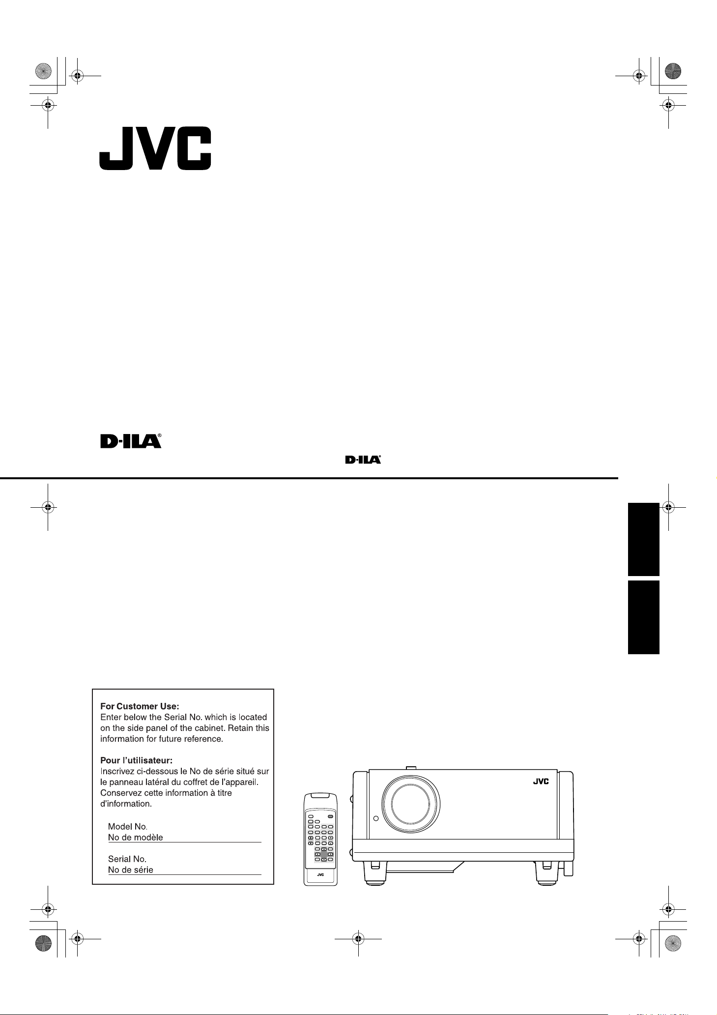
PROJECTOR
MANUEL D’INSTRUCTIONS : PROJECTEUR
DLA-G150CLU
INSTRUCTIONS
ENGLISHFRANÇAIS
DLA-G150CLU
QUICK
ALIGN.
W
W
SCREEN
SCREEN
S
S
PC1 PC2
KEYSTONE
RM-M160 REMOTE CONTROL UNIT
OPERATE
HIDE
FREEZE
COMP
VIDEO
DVI
Y/C
Y/C
T
T
DIGITAL
ZOOM FOCUS
ZOOM
W
W
PRESET
MENU
ENTEREXIT
(Lenses are optional)
LCT1123-001C
LCT1123-001B_Cover.fm Page 2 Thursday, February 21, 2002 2:50 PM
DLA-G150CLU/ LCT1123-001B
DLA-G150CLU&CLE_Eng.book Page 1 Thursday, February 21, 2002 2:39 PM
DLA-G150CLU / LCT1123-001B / ENGLISH
INSTRUCTIONS
PROJECTOR
DLA-G150CLU
Thank you for purchasing this projector. Before using it, read and follow all instructions
carefully to take full advantage of the projector’s capabilities.
ENGLISHFRANÇAIS
1
DLA-G150CLU&CLE_Eng.book Page 2 Thursday, February 21, 2002 2:39 PM
SAFETY PRECAUTIONS
DLA-G150CLU / LCT1123-001B / ENGLISH
IMPORTANT INFORMATION
WARNING :
TO PREVENT FIRE OR SHOCK HAZARDS, DO
NOT EXPOSE THIS APPLIANCE TO RAIN OR
MOISTURE.
CAUTION :
To reduce the risk of electric shock, do not remove
cover.
Refer servicing to qualified service personnel.
This projector is equipped with a 3-blade grounding-type
plug to satisfy FCC rule. If you are unable to insert the
plug into the outlet, contact your electrician.
FCC INFORMATION (U.S.A. ONLY)
CAUTION :
Changes or modification not approved by JVC could void
the user’s authority to operate the equipment.
NOTE :
This equipment has been tested and found to comply
with the limits for a Class B digital devices, pursuant to
Part 15 of the FCC Rules. These limits are designed to
provide reasonable protection against harmful
interference in a residential installation. This equipment
generates, uses, and can radiate radio frequency energy
and, if not installed and used in accordance with the
instructions, may cause harmful interference to radio
communications. However, there is no guarantee that
interference will not occur in a particular installation. If
this equipment does cause harmful interference to radio
or television reception, which can be determined by
turning the equipment off and on, the user is encourage
to try to correct the interference by one or more of the
following measures:
– Reorient or relocate the receiving antenna.
– Increase the separation between the equipment and
receiver.
– Connect the equipment into an outlet on a circuit
different from that to which the receiver is connected.
– Consult the dealer or an experienced radio/TV
technician for help.
About burning-in of the D-ILA device
Do not allow the same still picture to be projected for a long
time or an abnormally bright video picture to be projected.
Do not project video images with high-intensity or highcontrast on a screen. The video image could be burned in to
the D-ILA device.
Use special care when projecting video games or computer
program images. There is no problem with ordinary
video-cassette playback images.
IMPORTANT SAFEGUARDS
Electrical energy can perform many useful functions. This
unit has been engineered and manufactured to assure your
personal safety. But IMPROPER USE CAN RESULT IN
POTENTIAL ELECTRICAL SHOCK OR FIRE HAZARD. In
order not to defeat the safeguards incorporated into this
product, observe the following basic rules for its installation,
use and service. Please read these “Important Safeguards”
carefully before use.
– All the safety and operating instructions should be read
before the product is operated.
– The safety and operating instructions should be retained
for future reference.
– All warnings on the product and in the operating
instructions should be adhered to.
– All operating instructions should be followed.
– Place the projector near a wall outlet where the plug can
be easily unplugged.
– Unplug this product from the wall outlet before cleaning.
Do not use liquid cleaners or aerosol cleaners. Use a
damp cloth for cleaning.
– Do not use attachments not recommended by the
product manufacturer as they may be hazardous.
– Do not use this product near water. Do not use
immediately after moving from a low temperature to high
temperature, as this causes condensation, which may
result in fire, electric shock, or other hazards.
– Do not place this product on an unstable cart, stand, or
table. The product may fall, causing serious injury to a
child or adult, and serious damage to the product. The
product should be mounted according to the
manufacturer’s instructions, and should use a mount
recommended by the manufacturer.
– When the product is used on a cart, care
should be taken to avoid quick stops,
excessive force, and uneven surfaces
which may cause the product and cart to
overturn, damaging equipment or
causing possible injury to the operator.
– Slots and openings in the cabinet are provided for
ventilation. These ensure reliable operation of the
product and protect it from overheating. These openings
must not be blocked or covered. (The openings should
never be blocked by placing the product on bed, sofa,
rug, or similar surface. It should not be placed in a built-in
installation such as a bookcase or rack unless proper
ventilation is provided and the manufacturer’s
instructions have been adhered to.)
For proper ventilation, separate the product from other
equipment, which may prevent ventilation and keep /
distance more than 23-
5
/8" (60 cm).
About the installation place
Do not install the projector in a place that cannot support its
weight securely.
If the installation place is not sturdy enough, the projector
could fall or overturn, possibly causing personal injury.
2
DLA-G150CLU&CLE_Eng.book Page 3 Thursday, February 21, 2002 2:39 PM
DLA-G150CLU / LCT1123-001B / ENGLISH
– This product should be operated only with the type of
power source indicated on the label. If you are not sure
of the type of power supply to your home, consult your
product dealer or local power company.
– This product is equipped with a three-wire plug. This
plug will fit only into a grounded power outlet. If you are
unable to insert the plug into the outlet, contact your
electrician to install the proper outlet. Do not defeat the
safety purpose of the grounded plug.
– Power-supply cords should be routed so that they are not
likely to be walked on or pinched by items placed upon or
against them. Pay particular attention to cords at doors,
plugs, receptacles, and the point where they exit from the
product.
– For added protection of this product during a lightning
storm, or when it is left unattended and unused for long
periods of time, unplug it from the wall outlet and
disconnect the cable system. This will prevent damage
to the product due to lightning and power line surges.
– Do not overload wall outlets, extension cords, or
convenience receptacles on other equipment as this can
result in a risk of fire or electric shock.
– Never push objects of any kind into this product through
openings as they may touch dangerous voltage points or
short out parts that could result in a fire or electric shock.
Never spill liquid of any kind on the product.
– Do not attempt to service this product yourself as
opening or removing covers may expose you to
dangerous voltages and other hazards. Refer all service
to qualified service personnel.
– Unplug this product from the wall outlet and refer service
to qualified service personnel under the following
conditions:
a) When the power supply cord or plug is damaged.
b) If liquid has been spilled, or objects have fallen on the
product.
c) If the product has been exposed to rain or water.
d) If the product does not operate normally by following
the operating instructions. Adjust only those controls
that are covered by the Operation Manual, as an
improper adjustment of controls may result in damage
and will often require extensive work by a qualified
technician to restore the product to normal operation.
e) If the product has been dropped or damaged in any
way.
f ) When the product exhibits a distinct change in
performance – this indicates a need for service.
– When replacement parts are required, be sure the
service technician has used replacement parts specified
by the manufacturer or with same characteristics as the
original part. Unauthorized substitutions may result in
fire, electric shock, or other hazards.
– Upon completion of any service or repairs to this product,
ask the service technician to perform safety checks to
determine that the product is in proper operating
condition.
– The product should be placed more than one foot away
from heat sources such as radiators, heat registers,
stoves, and other products (including amplifiers) that
produce heat.
– When connecting other products such as VCR’s, and
personal computers, you should turn off the power of this
product for protection against electric shock.
– Do not place combustibles behind the cooling fan. For
example, cloth, paper, matches, aerosol cans or gas
lighters that present special hazards when over heated.
– Do not look into the projection lens while the illumination
lamp is turned on. Exposure of your eyes to the strong
light can result in impaired eyesight.
– Do not look into the inside of this unit through vents
(ventilation holes), etc. Do not look at the illumination
lamp directly by opening the cabinet while the
illumination lamp is turned on. The illumination lamp also
contains ultraviolet rays and the light is so powerful that
your eyesight can be impaired.
– Do not drop, hit, or damage the light-source lamp (lamp
unit) in any way. It may cause the light-source lamp to
break and lead to injuries. Do not use a damaged lightsource lamp. If the light-source lamp is broken, ask your
dealer to repair it. Fragments from a broken light-source
lamp may cause injures.
– Xenon gas is enclosed with high pressure inside the light-
source lamp (lamp unit) of this projector. If you drop or
impart a shock to the lamp, or discard it as is, there is the
possibility of explosion, leading to personal injury. Use
special care when handling the lamp. For any unclear
points, consult your product dealer.
– Do not “ceiling-mount” the projector to a place which
tends to vibrate; otherwise, the attaching fixture of the
projector could be broken by the vibration, possibly
causing it to fall or overturn, which could lead to personal
injury.
– Use only the accessory cord designed for this product to
prevent shock.
The power supply voltage rating of this product is
AC 120 V, the power cord attached conforms to the
following power supply voltage. Use only the power cord
designated by our dealer to ensure Safety and EMC.
When it is used by other power supply voltage, power
cable must be changed.
Ensure that the power cable used for the projector is the
correct type for the AC outlet in your country.
Consult your product dealer.
Power cord
Power supply voltage: AC 120 V
* DO NOT allow any unqualified person to
install the unit.
Be sure to ask your dealer to install the unit (eg.
attaching it to the ceilling) since special technical
knowledge and skills are required for installation.
If installation is performed by an unqualified person, it
may cause personal injury or electrical shock.
ENGLISHFRANÇAIS
3
DLA-G150CLU&CLE_Eng.book Page 4 Thursday, February 21, 2002 2:39 PM
Contents
DLA-G150CLU / LCT1123-001B / ENGLISH
SAFETY PRECAUTIONS ................. 2
Contents........................................... 4
Accessories ..................................... 5
Controls and Features .................... 6
Front Side / Top Surface / Right Side .....................6
Left-hand Side / Rear Side......................................7
Bottom Surface .......................................................8
Control Panel on the Projector ................................9
Connector Panel ...................................................11
Remote Control Unit..............................................12
Installing Batteries.................................................14
Precautions for using batteries..............................14
Installing the Projector.................. 15
Precautions for Installation....................................15
Adjusting the Inclination of the Projector...............16
Installing the Projector against the Screen............17
Projection Distance and Screen Size....................18
Setting the Amount of Lens Shifting......................19
Effective Range and Distance of the
Remote Control Unit..............................................20
Setting the Position Selecting Screw for Ceiling
Mounting ...............................................................21
When installing (adjusting/setting) the unit............21
Connecting to Various Devices.... 22
Signals that Can Be Input to the Projector ............22
Connecting to Video Devices ................................24
Connecting to Hi-Vision Devices/DVD Players .....25
Connecting to Other Devices ................................26
Connecting to Devices which Control the
Projector................................................................27
Connecting to Computer Devices .........................28
Connecting to DVI .................................................29
How to attach the ferrite core ................................29
Connecting the Power Cord ..................................30
Removing the Lens Cap........................................30
Basic Operations........................... 31
1. Turning on the Power........................................32
2. Select the Input source to be Projected ............33
3. Adjust the Screen Size (Zooming) ....................34
4. Adjust Focus .....................................................34
5. Setting the Screen Aspect Ratio .......................34
Turning off Image (HIDE) ......................................35
Removing the Trapezoidal Distortion of the
Image ....................................................................35
Quick Alignment Function (QUICK ALIGN.)..........36
Displaying a Still Picture (FREEZE) ......................37
Zooming a Part of the Image
(DIGITAL ZOOM T/W) ..........................................37
Menu Operations ........................... 38
Basic Menu Operation...........................................43
Changing the Color System
(Video Menu Mode Only) ......................................45
Changing the Language Display ...........................46
Changing the Screen aspect ratio/HDTV format
(Video Menu Mode Only) ......................................46
Adjusting Tracking/Phase .....................................47
Setting for Watching Image Software
(Video Menu Mode Only) ..................................... 48
Adjusting Picture Quality ...................................... 49
Adjusting Color temperature................................. 50
Adjusting the Video Screen/Menu Position .......... 51
Changing the Image Gamma/Aspect Ratio
(Video Menu Mode Only) ..................................... 52
Changing the Image Size - Resize Function
(PC Menu Mode Only).......................................... 53
Changing the Clamp pulse position
(PC Menu Mode Only).......................................... 53
Setting and Adjusting Other Functions
(OPTIONS)........................................................... 54
Getting Information............................................... 56
Replacing the Fuse........................ 57
Replacing the Light-Source
Lamp ...............................................58
Cleaning and Replacing the
Filter Cover..................................... 63
Troubleshooting............................. 64
Warning Indication......................... 66
Warning Messages ........................67
Specifications................................. 70
Outside dimensions.............................................. 72
Pin assignment (Specifications for terminals) ...... 73
RS-232C external control ..............74
Appendix......................................... 76
4
DLA-G150CLU&CLE_Eng.book Page 5 Thursday, February 21, 2002 2:39 PM
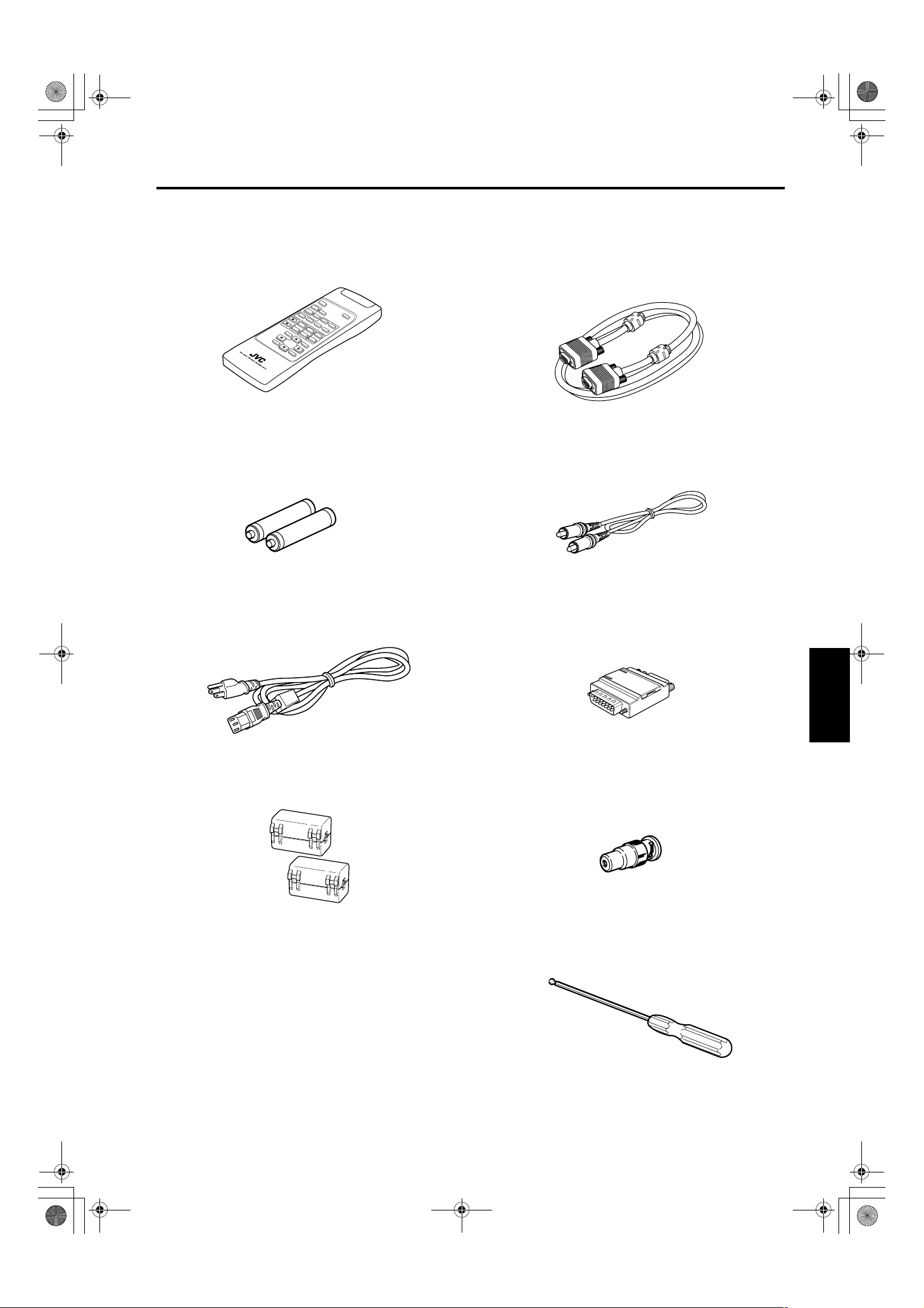
Accessories
The following accessories are included with this projector. Check for them; if any item is missing, please
contact your dealer.
DLA-G150CLU / LCT1123-001B / ENGLISH
■■■■ Remote control unit (RM-M160G)
■■■■ AA/R6-size dry cell battery (××××2)
(for checking operation)
■■■■ Power cord
[approx. 8.2 ft (approx. 2.5 m)]
■■■■ Personal computer connection cable
[approx. 6.56 ft (approx. 2 m)]
(D-sub, 3-row 15 pin)
■■■■ Video cable
[approx. 6.56 ft (approx. 2 m)]
■■■■ Conversion adapter for Mac
(for Macintosh)
■■■■ Ferrite core (××××2)
ENGLISHDEUTSHFRANÇAISITALIANOESPAÑOL
■■■■ BNC-RCA Conversion plug
■■■■ Hex. wrench
5
DLA-G150CLU&CLE_Eng.book Page 6 Thursday, February 21, 2002 2:39 PM
Controls and Features
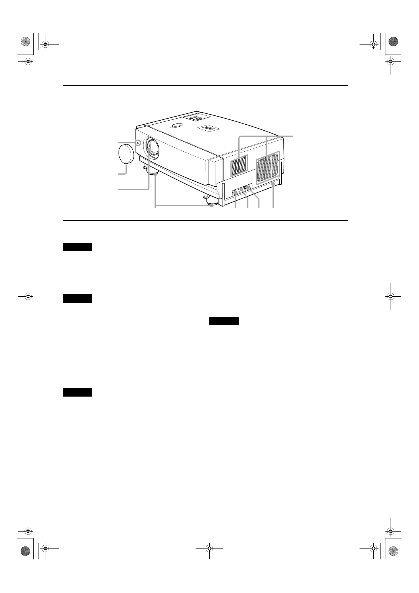
Front Side / Top Surface / Right Side
R
TE
N
E
U
N
E
M
EO
D
I
V
PC
E
AT
R
E
P
O
ET
S
E
E
R
N
P
O
T
E
S
Y
P
E
HID
K
EM
T
P
M
A
L
P
U
9
8
7
N
W
O
D
DLA-G150CLU / LCT1123-001B / ENGLISH
IT
X
E
1
6
Exhaust vents
1
Vents for cooling fans through which warm air comes out.
CAUTION
• Do not block the exhaust vents, or heat will build up inside,
possibly causing a fire. Also, do not touch the vents, or this
could give you a low-temperature burn.
Carrying handle
2
Raise this handle when carrying the projector.
CAUTIONS
• When carrying the projector, do not transmit shocks to it.
Also be careful to keep it balanced.
• Do not carry it while the light-source lamp is on or the
cooling fan is operating. This could cause personal injury.
AC IN (power input) terminal
3
This is the power input terminal where the supplied
power cord is connected. For details, refer to page 30.
Fuse holder
4
A fuse rated 12A/250V is installed. (Power source
protection)
To replace the fuse, refer to page 57.
CAUTION
• When replacing the fuse, use the same rating and type.
Otherwise, a fire may occur and/or the projector may be
damaged.
MAIN POWER switch
5
This is the main power switch. When it is turned on, the
projector goes into stand-by state, and the STAND BY
indicator on the control panel comes on. (Refer to
page 32.)
ON [ | ]: The main power turns on.
OFF [‡‡‡‡]: The main power turns off.
4
5
Adjustable feet (for adjusting the height and
6
3
2
angle)
By extending the feet, the projector angle can be
adjusted up to +7°.
For details, refer to “Adjusting the Inclination of the
Projector” on page 16.
Lens
7
One of the optional lens units should be installed before
using the projector.
A lens-hole blind cover (black one) is installed when the
projector is shipped from the factory.
For details on the types of optional lenses available, refer
to page 18.
CAUTION
• Please consult your authorized dealer or service center for
information about attaching an optional lens.
Lens cap
8
This is the lens cap provided for the optional lens.
When you are not using the projector, attach the lens cap
to protect the lens from dirt or being damaged. (Refer to
page 30.)
Remote sensor
9
When operating with the remote control, aim it toward
this sensor. (Refer to page 20.)
6
L
A
M
P
T
E
M
P
S
T
A
N
D
B
Y
M
E
N
U
K
E
Y
S
T
O
N
E
P
R
E
S
E
T
E
X
I
T
E
N
T
E
R
O
P
E
R
A
T
E
DLA-G150CLU&CLE_Eng.book Page 7 Thursday, February 21, 2002 2:39 PM
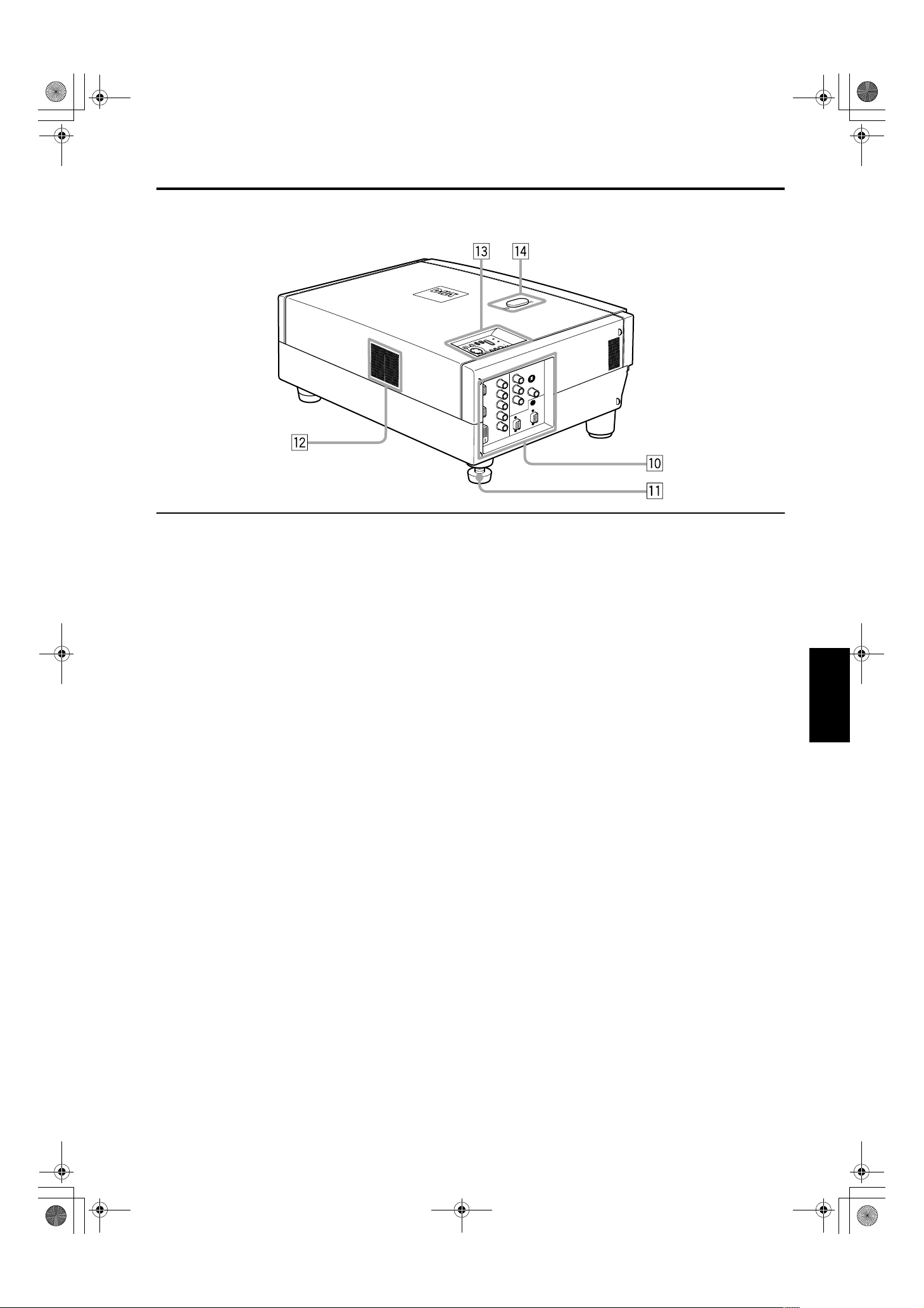
Left-hand Side / Rear Side
DLA-G150CLU / LCT1123-001B / ENGLISH
Controls and Features
U
P
D
O
W
N
H
I
D
E
P
C
V
I
D
E
O
p Connector panel
For details, refer to “Connector Panel” on page 11.
Rear adjustable foot (for leveling the projector)
q
It is set at the shortest position when shipped from the
factory. Turn the foot to make the projector level.
Adjustment can be made in the range of +1.5° and –1.5°
from the horizontal position. For details, refer to
“Adjusting the Inclination of the Projector” on page 16.
w Air inlet
This is the air inlet. Do not cover or obstruct this slot.
Control panel
e
For details, refer to “Control Panel on the Projector” on
page 9.
r Lens shift knob cap
When you have mounted a lens that uses the lens shift
function, open this cap and rotate the lens shift knob to
move the lens position. For more information, refer to
“Setting the Amount of Lens Shifting” on page 19.
ENGLISHDEUTSHFRANÇAISITALIANOESPAÑOL
7
DLA-G150CLU&CLE_Eng.book Page 8 Thursday, February 21, 2002 2:39 PM
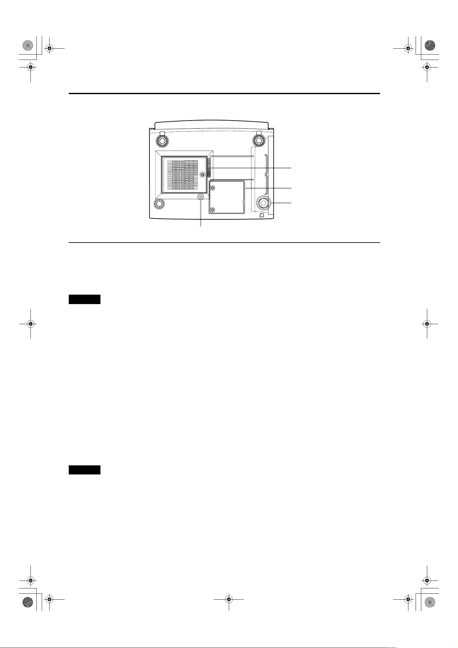
Controls and Features
Bottom Surface
DLA-G150CLU / LCT1123-001B / ENGLISH
t
y
u
i
t Air inlet (filter)
Air is taken in through the filter to cool the light-source
lamp. If the filter is blocked or if something that obstructs
the flow of air is placed around the projector, heat may
build up inside and could cause a fire. For required
space, refer to “Precautions for Installation” on page 15.
CAUTIONS
• Be careful as paper, cloth or soft cushion could be drawn in
if placed nearby. Do not block the filter, or heat may build
up and could cause a fire.
• Clean the filter periodically. For details, refer to “Cleaning
and Replacing the Filter Cover” on page 63. Deposition of
dirt on the filter reduces the cooling effect, causing heat to
build up inside, which could cause a fire or malfunction.
Opening for replacing the light-source lamp
y
For replacing the light-source lamp, refer to “Replacing
the Light-Source Lamp” on page 58.
u Fixing foot
i Position selecting screw for ceiling mounting
When using the projector in an upside-down, ceilingmounted position (inverted top-to-bottom and right-toleft), the “position selecting screw for ceiling mounting”
must be turned to switch to ceiling mounting.
This will correct variance in color images (shading),
which otherwise would occur in ceiling mounting.
For more information, refer to “Setting the Position
Selecting Screw for Ceiling Mounting” on page 21.
CAUTION
• To ceiling-mount and adjust the projector, special expertise
and technique are necessary. Be sure to ask your dealer or
specialist to perform this work.
8
LA
M
P
T
E
M
P
ST
A
N
D
B
Y
M
E
NU
KE
YS
T
O
NE
PR
E
S
ET
EX
IT
E
NT
E
R
O
P
ER
A
T
E
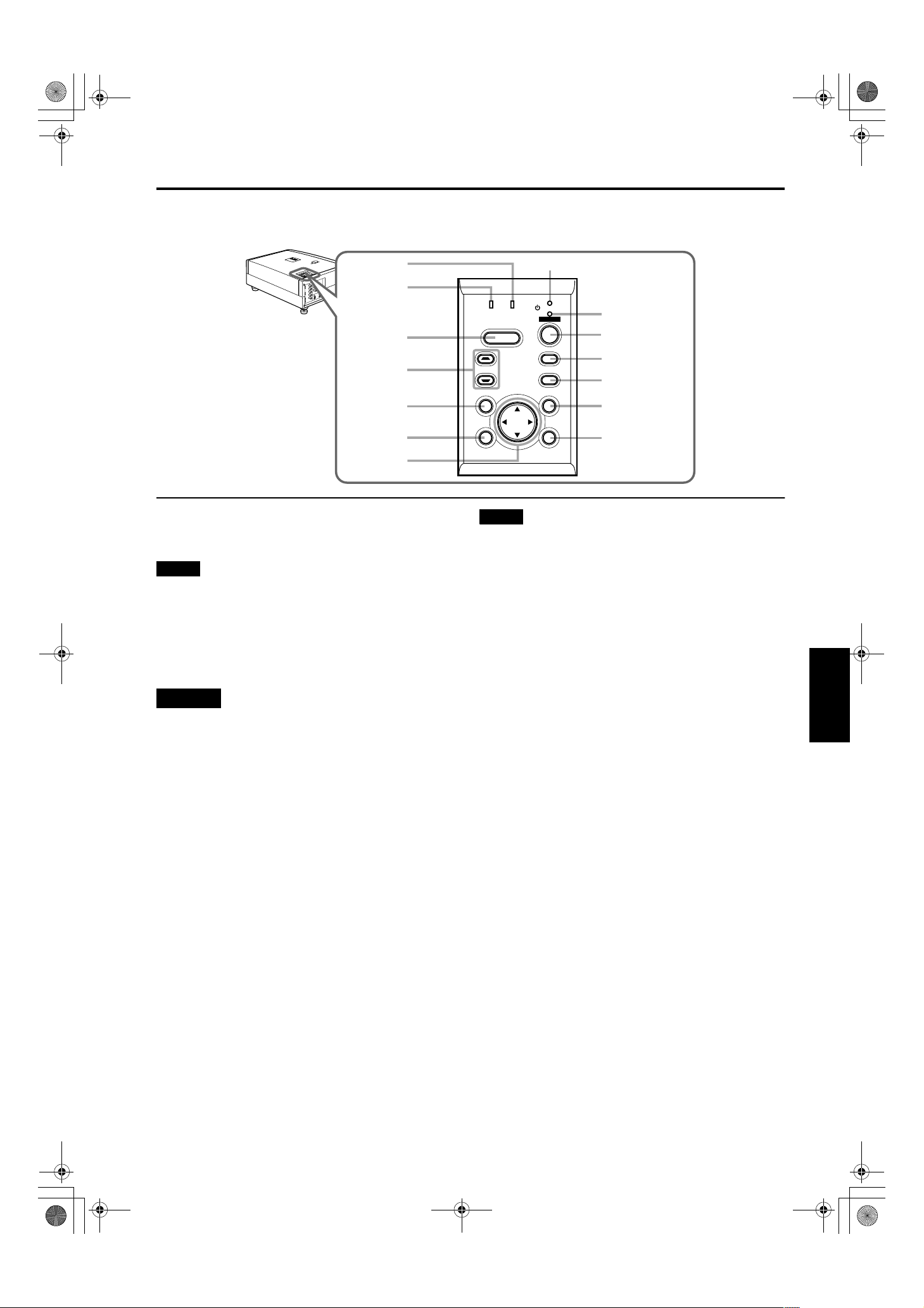
DLA-G150CLU&CLE_Eng.book Page 9 Thursday, February 21, 2002 2:39 PM
Control Panel on the Projector
U
P
D
O
W
N
H
ID
E
P
C
V
ID
E
O
r
e
w
q
p
LAMP TEMP
KEYSTONE
PRESET
HIDE
1
STAND BY
OPERATE
PC
VIDEO
MENU
DLA-G150CLU / LCT1123-001B / ENGLISH
Controls and Features
2
3
4
5
6
9
8
STAND BY Indicator
1
ON : When in stand-by mode.
Blinking :When in cool-down mode.
Memo
About the cool-down mode:
This projector has a function to cool down the heated lamp for a
fixed period of time (approx. 120 seconds) after projection is
finished. This feature is referred to as the cool-down mode.
The purpose of the cool-down mode is to prevent inner parts
from being deformed or broken by heat from the heated lamp
as well as to prolong the life of the lamp.
CAUTIONS
• Do not turn off the MAIN POWER switch while in the cooldown mode.
• Do not place the projector on its side or stand it upright
while in the cool-down mode; this may block the vents.
2 OPERATE indicator
ON : When the projector is in operation (projecting).
OFF : When the projector is not in operation (not
projecting).
OPERATE button
3
When the projector is in the stand-by mode, press this
button one second or more, and the projector is turned
on, causing the OPERATE indicator to light.
Press it one second or more again, and the projector
goes into the cool-down mode, then stand-by mode.
(Refer to page 32.)
* You cannot use the OPERATE button for about one
minute after the lamp blinks. Press the button after a
minute or longer has elapsed.
EXIT ENTER
7
Memo
While in the cool-down mode (STAND BY indicator is blinking):
Even if you press the OPERATE button, the projector is not
turned on. Wait until the projector enters stand-by mode
(STAND BY indicator stays lit).
4 PC button
Use this button to select a device connected to the PC 1,
PC 2 or DVI terminals. Each time you press the button,
the selection alternates among PC 1, PC 2 and DVI.
* “PC1” , “PC2” or “DVI” will be displayed on the top right of
the projected image. (This function can be disabled by
the menu.)
5 VIDEO button
Use this button to select a device such as a video deck
connected to the AV IN (Y/C, VIDEO or COMP) terminal
of the projector. Each time you press the button, the
selection alternates among Y/C, VIDEO and COMP.
* “Y/C”, “VIDEO” or “COMP” will be displayed on the top right of
the projected image. (This function can be disabled by the
menu.)
MENU button
6
Use this button to enter or exit the menu mode. The main
menu appears or disappears at the screen. For details,
refer to “Basic Menu Operation” on page 43.
ENTER button
7
This button will be used in the menu mode. Use to
display the hierarchical menus. Also use when “ENTER”
is displayed against the item on the menu screen or
when the “All reset” selection is confirmed. For details,
refer to “Basic Menu Operation” on page 43.
Cursor buttons 5/∞/2/
8
These buttons will be used in the menu mode to select an
item, or to set or adjust the value. For details, refer to
“Basic Menu Operation” on page 43.
3
ENGLISHDEUTSHFRANÇAISITALIANOESPAÑOL
9
DLA-G150CLU&CLE_Eng.book Page 10 Thursday, February 21, 2002 2:39 PM
Controls and Features
9 EXIT button
This button will be used in the menu mode to return to the
previous menu. When the main menu is displayed, this
button will cause the menu to disappear. For details, refer
to “Basic Menu Operation” on page 43.
p PRESET button
This PRESET button only works as a reset button for the
direct button adjustment of the KEYSTONE button of the
control panel and the DIGITAL ZOOM button of the
remote control. When adjusting the keystone or digital
zoom (when the setting is displayed on the screen) the
adjusted value is reset to that which was set when the
projector was shipped from the factory. Of the menu
items, this button only works for the keystone setting
screen.
q KEYSTONE / buttons
Use these buttons to correct a trapezoidal distortion of
the projected image. (Refer to page 35.)
HIDE button
w
Use this button to turn off the image on the screen
temporarily. Pressing it again restores the image to
resume. (Refer to page 35.)
LAMP indicator
e
ON : After the light-source lamp has been used for
more than approx. 900 hours. (NORMAL only)
Blinking
: After the light-source lamp has been used for
more than approx. 1000 hours (1900 hours in the
LPC or LOC mode). Replace the light-source
lamp. Refer to “Replacing the Light-Source
Lamp” on page 58 or page 59.
r TEMP indicator
Blinking : The temperature inside the projector has risen
abnormally.
DLA-G150CLU / LCT1123-001B / ENGLISH
Note
• While the TEMP indicator is blinking (during abnormal
temperature), the power is automatically cut off.
10
L
A
M
P
T
E
M
P
S
T
A
N
D
B
Y
M
E
N
U
K
E
Y
S
T
O
N
E
P
R
E
S
E
T
E
X
I
T
E
N
T
E
R
O
P
E
R
A
T
E
DLA-G150CLU&CLE_Eng.book Page 11 Thursday, February 21, 2002 2:39 PM
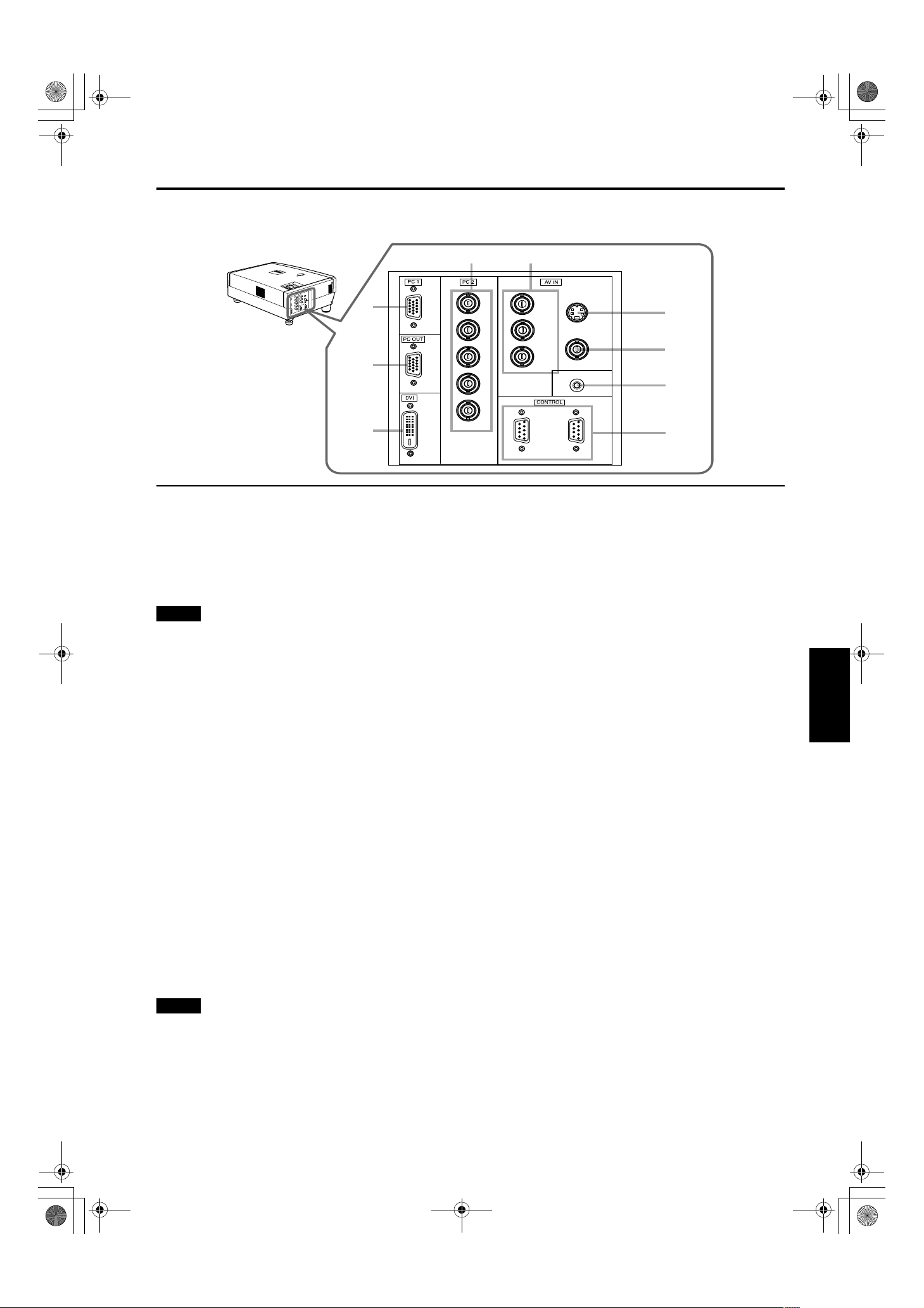
Connector Panel
DLA-G150CLU / LCT1123-001B / ENGLISH
Controls and Features
U
P
D
O
W
N
H
I
D
E
P
C
V
I
D
E
O
1
2
3
1 PC (computer) 1 input terminal (D-sub 3-row 15
pin)
This is an input terminal dedicated to computer signals
(RGB video signals and sync signals).
Connect the display output terminal of the computer to
this terminal. When a Macintosh computer is to be
connected, use the supplied conversion adapter for Mac.
Note
• When computer-related signals are input, the uppermost
edge of the image may appear to bow if the sync signal
input is composite sync (Cs) or G on sync signal. In this
case, use separate sync signals for vertical sync (V) and
horizontal sync (H).
2 PC (computer) OUT terminal (D-sub 3-row 15 pin)
This is the terminal for video output from the monitor of
the computer connected to PC1 or PC2.
The computer input signal projected on the screen is
output. A display monitor can be used by connecting it to
this terminal.
3 DVI terminal [DVI-D 24 pin]
This is the digital RGBHV input terminal.
• The Mac ADC is not supported.
4 PC (computer) 2 input terminals (BNC ×
These are multipurpose video input terminals that allow
input of the following signals.
• Analog RGB signals, vertical sync (V) signals, and
horizontal sync (H) signals / composite signals (Cs).
(Devices which have analog RGB signal output
terminals can be connected.)
* Input of external sync signals is automatically detected.
Detection of H/V signals or Cs signals causes automatic
switching to external sync. The priority order is H/V > Cs.
IN
5)
×××
54
R
G
B
H
V
Y
B
/B-Y
P
R
/R-Y
P
REMOTE
Y/C
VIDEO
6
7
8
9
IN OUT
5 Component terminal
Component signals (Y, B-Y, R-Y) or DTV-format (Y, PB,
) signals. (Devices which have component output
R
P
terminals can be connected.)
* For details about DTV-format signals (480i, 480p, 720p,
1080i) compatible with this unit, refer to page 22.
6 Y/C (S-video) input terminal (Mini DIN 4 pin)
Connect this terminal to the S-video output terminal of a
video deck, etc.
Attach the ferrite core (accessory) to the cable which is
connected to the Y/C input terminal. (Refer to page 29.)
7
VIDEO (composite video) input terminal (BNC)
Connect this terminal to the composite video output
terminal of a video deck, etc.
REMOTE terminal (stereo mini jack)
8
Connect an infrared remote control extension unit, etc. to
this jack.
Attach the ferrite core (accessory) to the cable which is
connected to the REMOTE terminal. (Refer to page 29.)
* For details, consult your dealer.
RS-232C CONTROL terminal IN/OUT (D-sub 9 pin)
9
This is the RS-232C interface-specified terminal. The
projector can be controlled by a computer connected
externally.
* For details, refer to page 27 and 74.
ENGLISHDEUTSHFRANÇAISITALIANOESPAÑOL
Note
• When computer-related signals are input, the uppermost
edge of the image may appear to bow if the sync signal
input is composite sync (Cs) or G on sync signal. In this
case, use separate sync signals for vertical sync (V) and
horizontal sync (H).
11
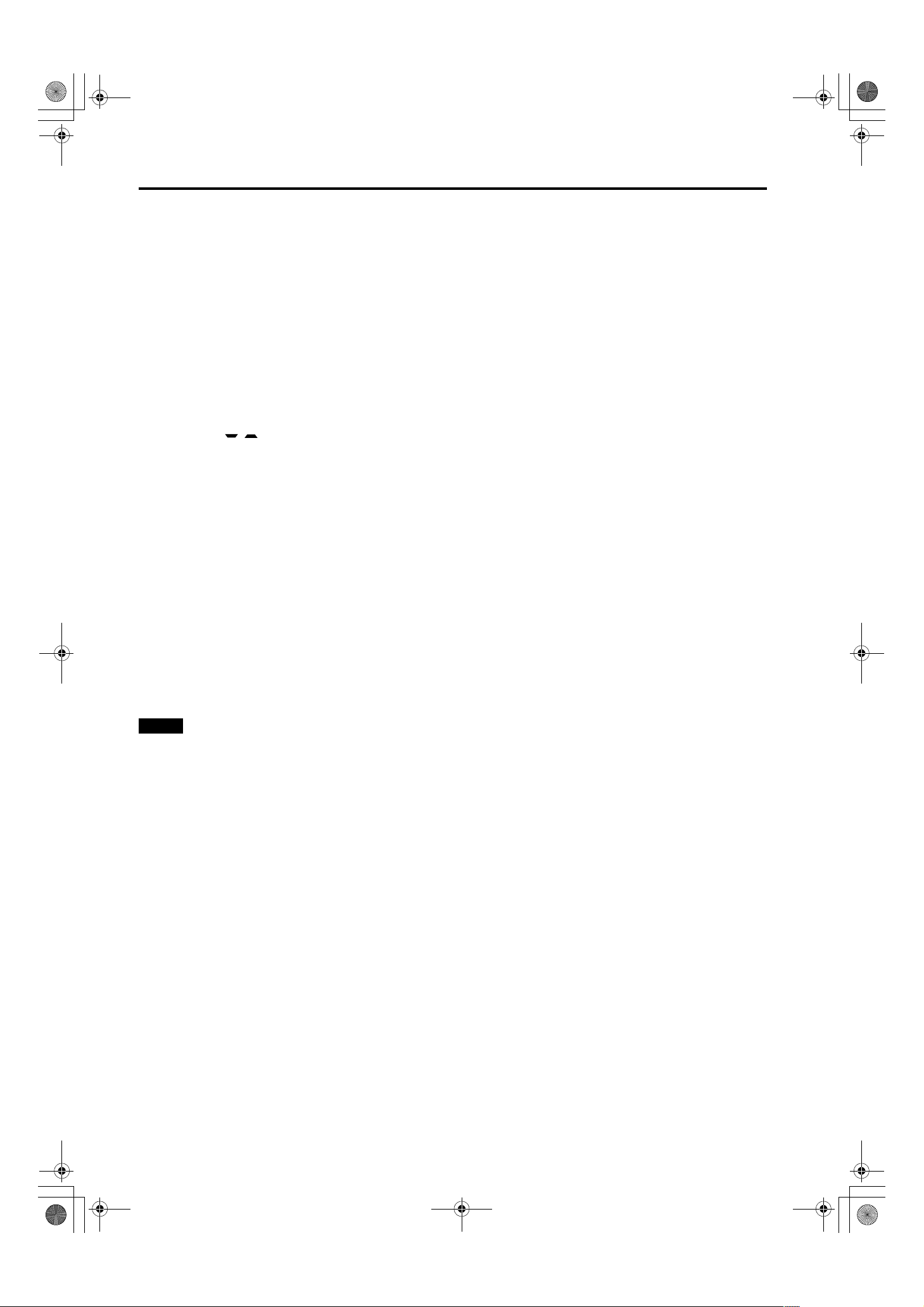
Eng_Body.fm Page 12 Wednesday, May 15, 2002 10:17 AM
Controls and Features
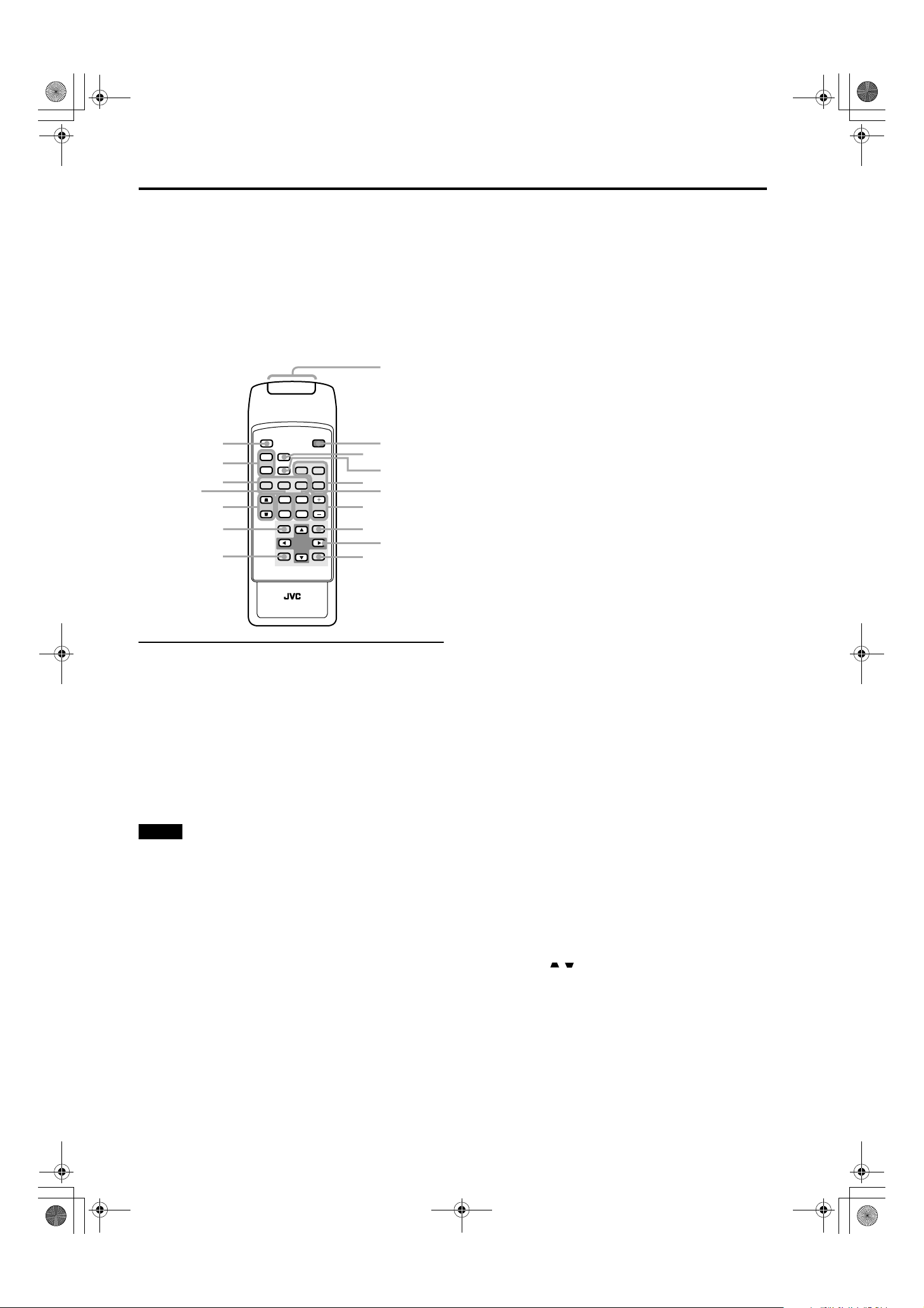
Remote Control Unit
DLA-G150CLU / LCT1123-001C / ENGLISH
On the remote control, the same buttons as on the control
panel of the projector are provided except for the following
buttons. For the same buttons, operation is the same in
principle.
For remote control only:
DIGITAL ZOOM T/W, QUICK ALIGN., FREEZE, ZOOM T/
W, FOCUS +/–, SCREEN W/S, PC 1, PC 2, VIDEO, Y/C,
DVI, COMP.
1
r
u
y
t
e
w
QUICK
ALIGN.
W
W
SCREEN
SCREEN
S
S
PC1 PC2
KEYSTONE
HIDE
FREEZE
DIGITAL
ZOOM
PRESET
T
W
OPERATE
COMP
VIDEO
DVI
T
ZOOM FOCUS
W
MENU
2
3
Y/C
5
4
6
7
8
9
q
RM-M160 REMOTE CONTROL UNIT
ENTEREXIT
1 Remote control’s signal transmitter
2 OPERATE button
When the projector is in the stand-by mode, press this
button one second or more, and the projector is turned
on, causing the OPERATE indicator to light.
Press it one second or more again, and the projector
goes into the cool-down mode, then stand-by mode.
(Refer to page 32.)
* The OPERATE button will not work for approximately 1
minute from when the light-source lamp is turned on. Use
the button after approximately 1 minute.
Memo
While in the cool-down mode (STAND BY indicator is
blinking):
Even if you press the OPERATE button, the projector is not
turned on. Wait until the projector enters stand-by mode
(STAND BY indicator stays lit).
HIDE button
3
Use this button to turn off the image on the screen
temporarily. Pressing it again makes the image to
resume. (Refer to page 35.)
FREEZE button
4
During projection of an image on the screen, press this
button to obtain a still picture.
To restore normal projection, press it again. (Refer to
page 37.)
* Depending on the video signal source (UXGA 60Hz,
SXGA 60Hz), this button does not work.
p
5 VIDEO button
Use this button to select a device such as a video deck
connected to the AV IN terminal (VIDEO, Y/C or COMP
input terminal) of the projector. Each time you press the
button, the selection alternates among Y/C, VIDEO and
DVI. (Refer to page 33.)
* “Y/C”, “VIDEO” or “DVI” will be displayed on the top right
of the projected image. (This function can be disabled by
the menu.)
6 ZOOM T/W buttons
Use these buttons to adjust the projected screen size.
T (Tele): The projected screen size decreases.
W (Wide):The projected screen size increases.
7 FOCUS +/– buttons
Use these buttons to adjust the focus of the projected
video image.
+ : The focus point becomes more distant.
– : The focus point becomes nearer.
MENU button
8
Use this button to enter or exit the menu mode. The main
menu appears or disappears at the screen. For details,
refer to “Basic Menu Operation” on page 43.
Cursor buttons 5/∞/2/
9
These buttons are used in the menu mode to select an
item or to set or adjust the value. For details, refer to
“Basic Menu Operation” on page 43.
ENTER button
p
This button is used in the menu mode. Use to display the
hierarchical menus. Also use when “ENTER” is displayed
against the item on the menu screen or when the “All
reset” selection is confirmed. For details, refer to “Basic
Menu Operation” on page 43.
EXIT button
q
This button is used in the menu mode to return to the
previous menu. When the main menu is displayed, this
button will cause the menu to disappear. For details, refer
to “Basic Menu Operation” on page 43.
PRESET button
w
This PRESET button only works as a reset button for the
direct button adjustment of the KEYSTONE button of the
control panel and the DIGITAL ZOOM button of the
remote control. When adjusting the keystone or digital
zoom (when the setting is displayed on the screen) the
adjusted value is reset to that which was set when the
projector was shipped from the factory. Of the menu
items, this button only works for the keystone setting
screen.
KEYSTONE / buttons
e
Use these buttons to correct a trapezoidal distortion of
the projected image. (Refer to page 35.)
3
12
Eng_Body.fm Page 13 Wednesday, May 15, 2002 10:16 AM
r DIGITAL ZOOM T/W buttons
A part of image can be magnified up to four times on the
screen.
Each time the T or W button is pressed, the image is
enlarged or the enlarged image is reduced by a certain
degree. (Refer to page 37.)
* Images which are enlarged with the digital zoom become
less clear.
* Depending on the video signal source (UXGA 60Hz,
SXGA 60Hz), this button does not work.
t PC buttons
Use these buttons to select a device connected to the PC
1, PC 2 or DVI terminals. (Refer to page 33.)
* “PC 1”, “PC 2” or “DVI” will be displayed on the top right
of the projected image. (This function can be disabled
using the menu.)
y SCREEN W/S buttons
Changes the projection screen size to [4:3] or [16:9].
u QUICK ALIGN. (Quick Alignment) button
Use this button to automatically align “Horizontal and
vertical position”, “Tracking” and “Phase” for the
projected image.
During the automatic alignment, “Quick Alignment”
appears on the screen, and disappears after alignment is
finished. (Refer to page 36.)
* The “Quick Alignment” function only works when the
signal is input from the input terminal of PC 1, PC 2 or
DVI. It does not work when the signal is input from the
VIDEO IN terminal (VIDEO, Y/C and COMP. input
terminal).
DLA-G150CLU / LCT1123-001C / ENGLISH
Controls and Features
CAUTION
• Automatic alignment with the quick alignment function
should be carried out on a bright still-picture. This function
may not work correctly on a dark picture or motion-picture.
If adjustment with this function is not satisfactory, adjust
“Horizontal and vertical position”, “Tracking” and “Phase” in
the menu mode.
ENGLISHDEUTSHFRANÇAISITALIANOESPAÑOL
13
DLA-G150CLU / LCT1123-001B / ENGLISH
DLA-G150CLU&CLE_Eng.book Page 14 Thursday, February 21, 2002 2:39 PM
Controls and Features
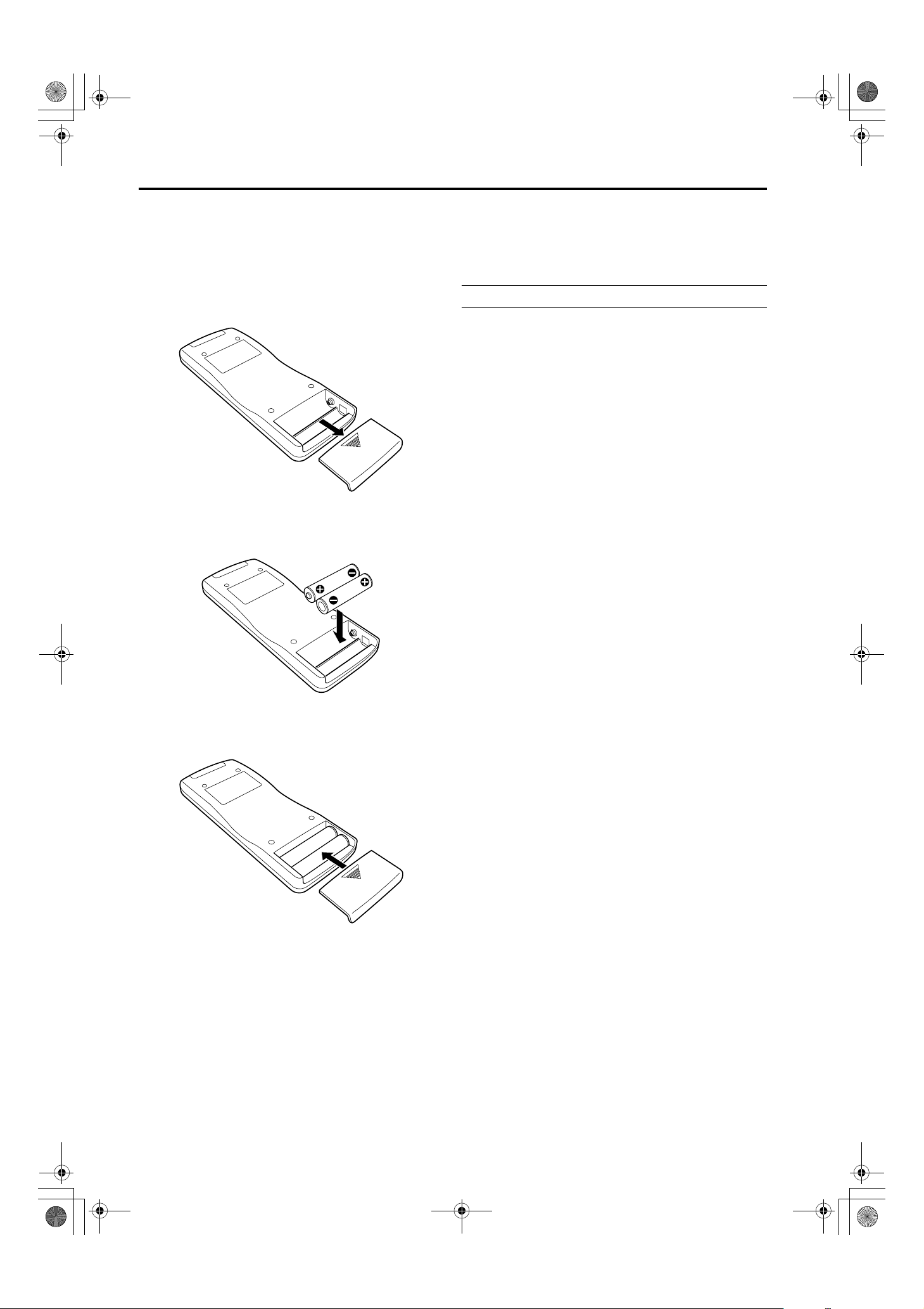
Installing Batteries
Install batteries in the remote control. If the remote control has started to work erratically, replace the
batteries.
Open the back cover.
1
Open the back cover in the direction of the arrow.
Install the batteries.
2
Place the two supplied batteries (AA/R6-size) in the
remote control as illustrated below.
Precautions for using batteries
If batteries are used incorrectly, they may crack or
leak liquid. This could cause a fire, burn, malfunction,
or staining or damaging of the surroundings.
Beware of the following:
• Do not mix new and old batteries.
• Do not mix different types of batteries as they differ in
characteristics.
• Place batteries so they match the polarities indicated:
(+) to (+) and (–) to (–).
• Be sure to put the minus (–) end in first to avoid
short-circulating.
• Use only designated batteries.
• Remove the batteries if the remote is not to be used for a
prolonged period.
• When the batteries are exhausted, replace them
immediately. Otherwise, liquid could leak, or malfunction
could occur due to leaking liquid. If the leaked liquid
contacts the skin, wipe it off with a cloth, otherwise the skin
could become rough.
• Do not put batteries into a fire or try to recharge them.
• Batteries run for six months to one year in normal use.
However, the batteries supplied are for confirming
operation and may not run that long. When the remote
control starts failing to work properly, replace the batteries
with new ones.
Close the back cover.
3
First fit the claws on the back cover in the case, then
close the back cover in the direction of the arrow.
14
DLA-G150CLU&CLE_Eng.book Page 15 Thursday, February 21, 2002 2:39 PM
Installing the Projector
Precautions for Installation
CAUTIONS
1. Before installation, do not connect the projector’s power cord.
2. Do not install the projector in the following places:
• Where there is water, humidity or dust.
• Where the projector may be subjected to oil, smoke or cigarette smoke.
• On a soft surface such as a carpet or cushion.
• Where the projector may be subjected to direct sunlight.
• Where temperature is high or humidity is low.
Allowable operation temperature range: 41°F to 95°F (+5°C to +35°C)
Allowable relative humidity range: 20% to 80% (no condensation)
Allowable storage temperature range: 14°F to 140°F (–10°C to +60°C)
■
When installing the projector, observe the following:
• Do not use the projector placed on its side.
Avoid using the projector placed on its side. This could cause a malfunction.
• Use the projector within the specified angle.
Do not use the projector inclined ±30° horizontally (left/right). This could cause color variation or shorten the lamp life.
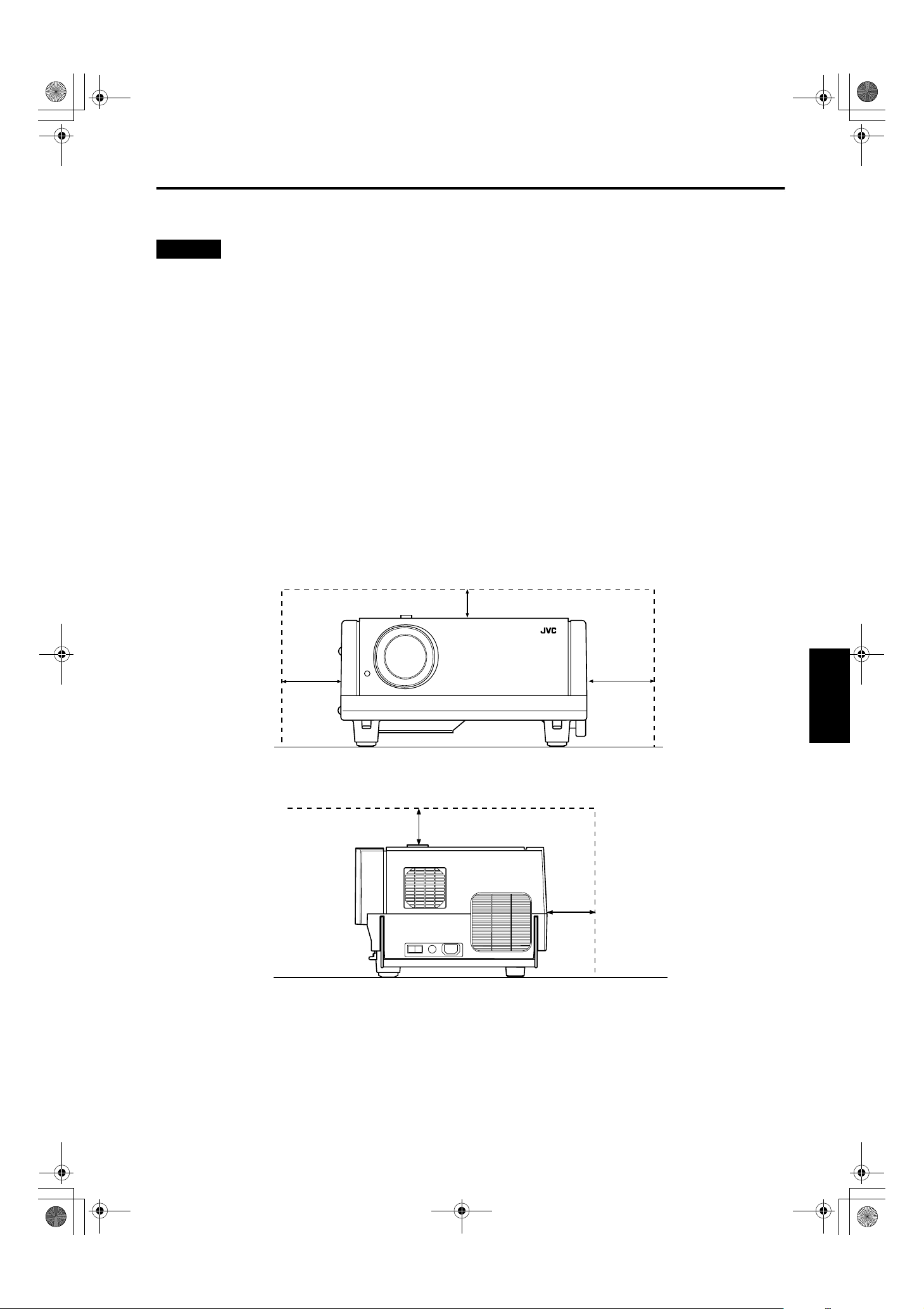
• Do not block the exhaust vents.
Do not use a cover which encloses the projector air-tight or blocks the exhaust vents. Allow sufficient space around the
projector. When the projector is enclosed in a space of the following dimensions, use an air conditioner so the temperature
inside becomes equal to the outside temperature.
DLA-G150CLU / LCT1123-001B / ENGLISH
Allowable minimum space required
200mm
300mm
600mm
ENGLISHDEUTSHFRANÇAISITALIANOESPAÑOL
300mm
200mm
15
DLA-G150CLU / LCT1123-001B / ENGLISH
DLA-G150CLU&CLE_Eng.book Page 16 Thursday, February 21, 2002 2:39 PM
Installing the Projector
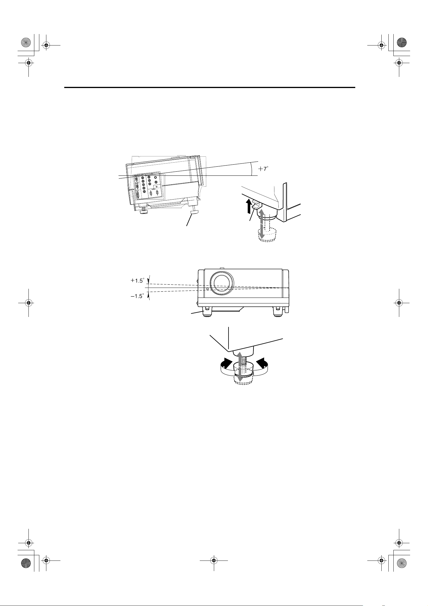
Adjusting the Inclination of the Projector
The vertical angle and the leveling of the projector can be adjusted with the adjustable feet at the bottom of the projector.
Adjusting the vertical angle of the projector
■
While pushing the levers on both sides upward, raise the projector. The adjustable feet automatically extend.
To retract the feet, push the levers and lower the projector slowly; the projector is fixed at the position
where you release the levers.
Y
Y/C
R
-Y
/B
B
P
G
VIDEO
-Y
/R
R
P
B
REMOTE
H
DVI
V
IN
OUT
IN
Adjustable feet (at the front)
lever
Leveling the projector
■
Lift the projector, rotate the rear adjustable foot, and adjust the horizontal angle until the projector is level.
Adjustable foot (at the rear)
Fixing foot (at the rear)
ShortenExtend
16
DLA-G150CLU&CLE_Eng.book Page 17 Thursday, February 21, 2002 2:39 PM
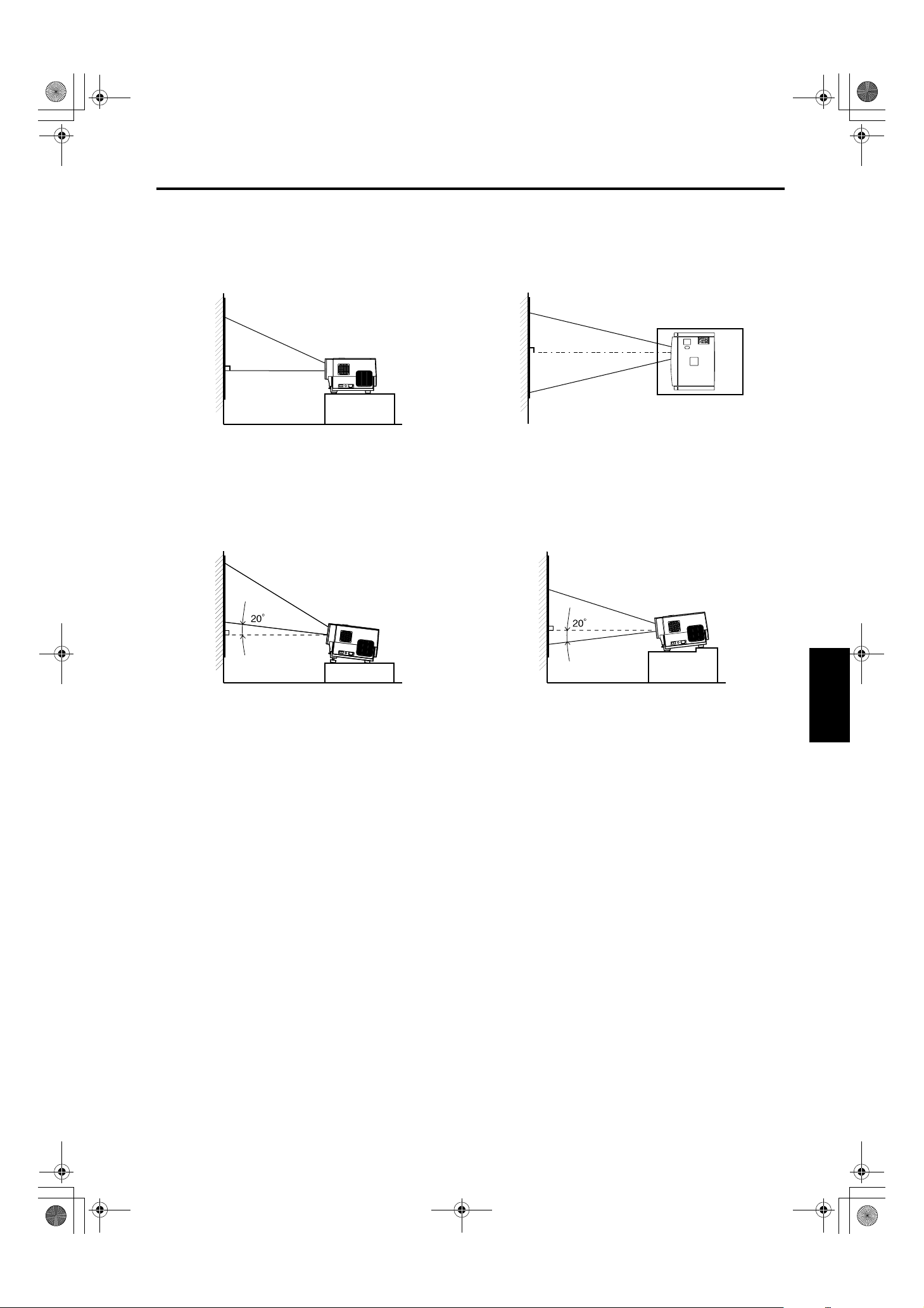
Installing the Projector against the Screen
The projector should be placed so that the center line of the lens is at a right angle to the screen as shown in the following
figures.
Side view
■
Top view
■
DLA-G150CLU / LCT1123-001B / ENGLISH
Installing the Projector
PC
MENU
VIDEO
STAND BY
OPERATE
HIDE
LAMPTEMP
PRESET
ESCAPE ENTER
KEYSTONEVOLUME
Trapezoidal-distortion correctable maximum angle
■
The projector has a function to correct the trapezoidal distortion of the projected image on the screen.
To correct this distortion, use the KEYSTONE buttons on the projector. (Refer to “Removing the Trapezoidal Distortion of the
Image” on page 35.) Also, correction is possible by using the “Keystone” menu. (Refer to “Setting and Adjusting Other
Functions (OPTIONS)” on page 54.)
Correctable angle:
Up to approx. 20° upward from the horizontal line
Correctable angle:
Up to approx. 20° downward from the horizontal line
ENGLISHDEUTSHFRANÇAISITALIANOESPAÑOL
17
DLA-G150CLU / LCT1123-001B / ENGLISH
DLA-G150CLU&CLE_Eng.book Page 18 Thursday, February 21, 2002 2:39 PM
Installing the Projector
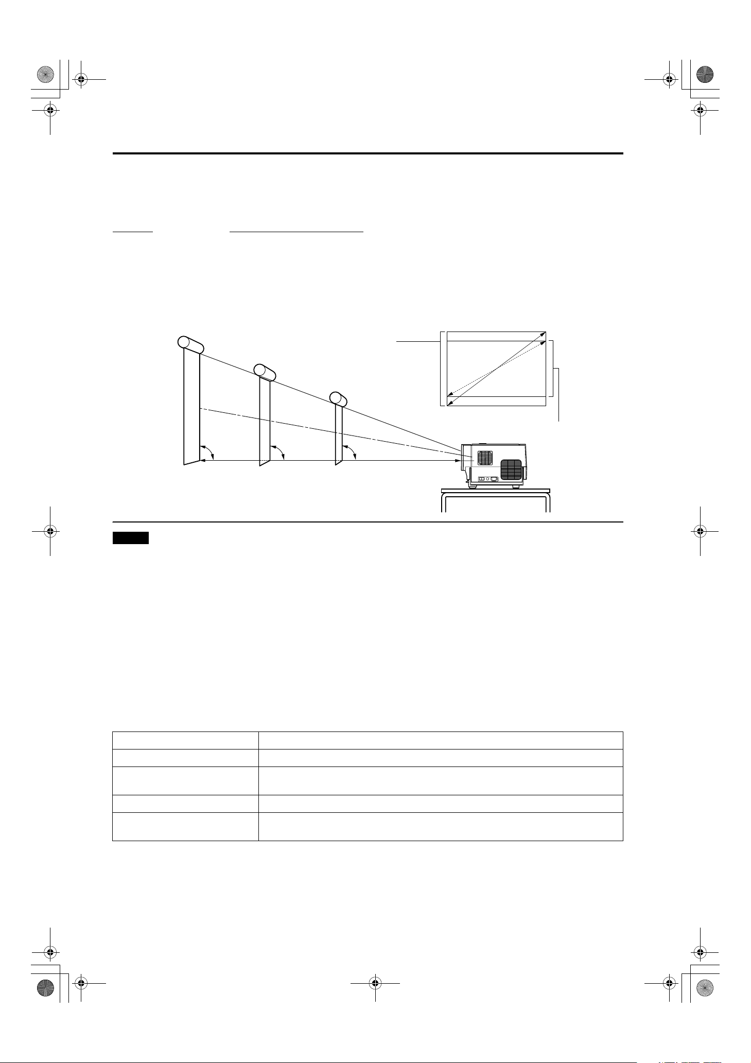
Projection Distance and Screen Size
• The range of projection distances that can be focused depends on the lens unit (optional) to be used. When the aspect ratio
of the screen is 4:3, the range is as follows and you need to install the projector within this range.
Lens type
GL-M2910G 0.77 m to 4.03 m
GL-M2915SG 1.76 m to 4.50 m
GL-M2920ZG 2.77 m to 19.71 m
GL-M2930SZG 4.74 m to 29.87 m
*: The value for projection distance is a guide (reference) one. The projected image size may vary depending on the
manufacturing tolerance of the projection lens.
Screen
To move the Shift position by 50%, set the bottom edge of the projection screen so that it is at the same height as the center of the lens.
Approximate projection distance
Change of projection screen
according to aspect ratio
Screen with 4:3 aspect ratio
Screen with 16:9 aspect ratio
90˚ 90˚ 90˚
Center line of the lens
Notes
• For detailed relationship between projection distances and projection screen sizes, refer to Appendix A. The relationships for
both 4:3 and 16:9 ratios are listed there.
• When installing a screen, use a 4:3 aspect-ratio picture.
• (A 16 : 9 aspect-ratio picture is projected based on the width of the range in which a 4:3 aspect-ratio picture is projected.)
• The diagonal length of a 16:9 aspect-ratio screen is about 91.8% that of a 4:3 aspect-ratio screen. This value is only a guide
(reference).
• If sunlight or lamp light strikes the projection screen directly, the picture tends to become pale and dim. Use a curtain or
other means to shield the light.
• Set the projector horizontally on a surface that is within the range of adjustable angles (up/down adjustment angle: +7° ;
horizontal adjustment angle: ±1.5°).
• If the keystone is adjusted, the projected screen becomes smaller.
• When hanging from the ceiling, use a dedicated hanging fixture (not supplied).
■ Optional Lenses
This projector does not include a lens. You can select one of the optional lenses to adjust the projection distance. Please ask
your authorized dealer or service center to install the lens.
Lens model Function
GL-M2910G Powered focus for rear projection, short focal length (subject ratio 1:1), 0% influence.
GL-M2915SG
GL-M2920ZG Powered zoom/powered focus lens (subject ratio 2:1-3:1), 50% influence.
GL-M2930SZG
Powered focus, short focal length (subject ratio 1.5:1), powered image adjustment (2%
zoom), includes manual vertical shift function, 30%-55% influence
Powered zoom/powered focus long focal length lens (subject ratio 2.9:1-5.5:1), includes
manual vertical shift function, 30%-55% influence.
18
DLA-G150CLU&CLE_Eng.book Page 19 Thursday, February 21, 2002 2:39 PM
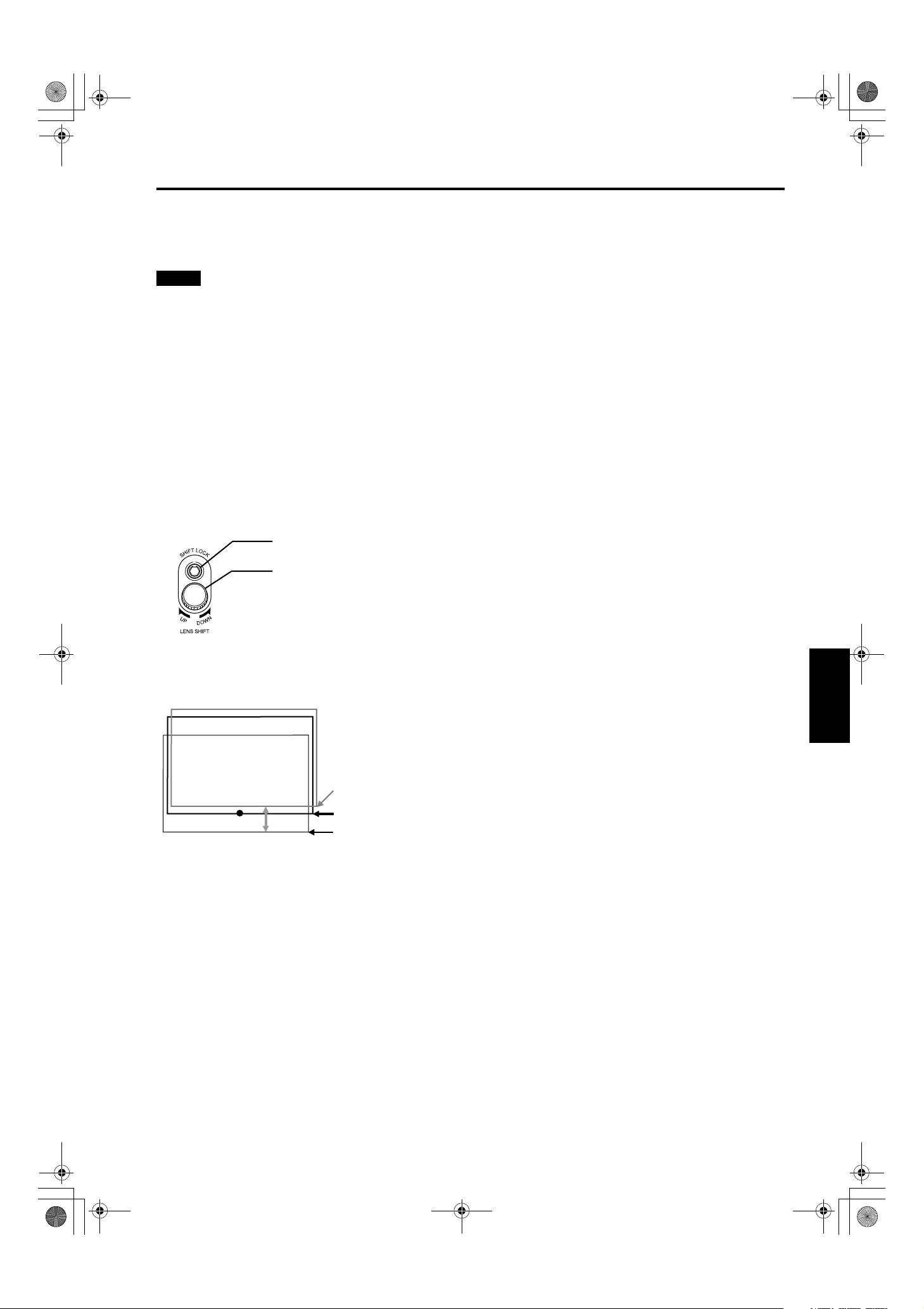
Setting the Amount of Lens Shifting
When the lens unit (optional) with the lens shifting function is used, the projected screen can be shifted up and down in
position.
Notes
• The amount of shifting is within the range of approx. 30% to 55%.
• After finishing the lens shift setting, tighten the SHIFT LOCK fixing bolt firmly so that the lens will not move.
Turn the cap on the top of the projector to open it.
1
Loosen the SHIFT LOCK fixing bolt.
2
Use the hex. wrench supplied.
Rotate the LENS SHIFT knob to adjust the position (shift amount) of the projected
3
screen.
Rotate it to the right: The lens shifts upward.
Rotate it to the left: The lens shifts downward.
DLA-G150CLU / LCT1123-001B / ENGLISH
Installing the Projector
Tighten the SHIFT LOCK fixing bolt firmly.
4
Use the hex. wrench supplied.
Turn the cap to close it.
5
SHIFT LOCK fixing bolt
LENS SHIFT knob
■ Projected screen position image by amount of shift
* The projected screen position can only shift in an up-and-down direction.
The illustration shows the screen shifted sidewise for the purpose of explanation.
Approx. 55%
Approx. 50%
Approx. 30%
ENGLISHDEUTSHFRANÇAISITALIANOESPAÑOL
19
DLA-G150CLU / LCT1123-001B / ENGLISH
DLA-G150CLU&CLE_Eng.book Page 20 Thursday, February 21, 2002 2:39 PM
Installing the Projector
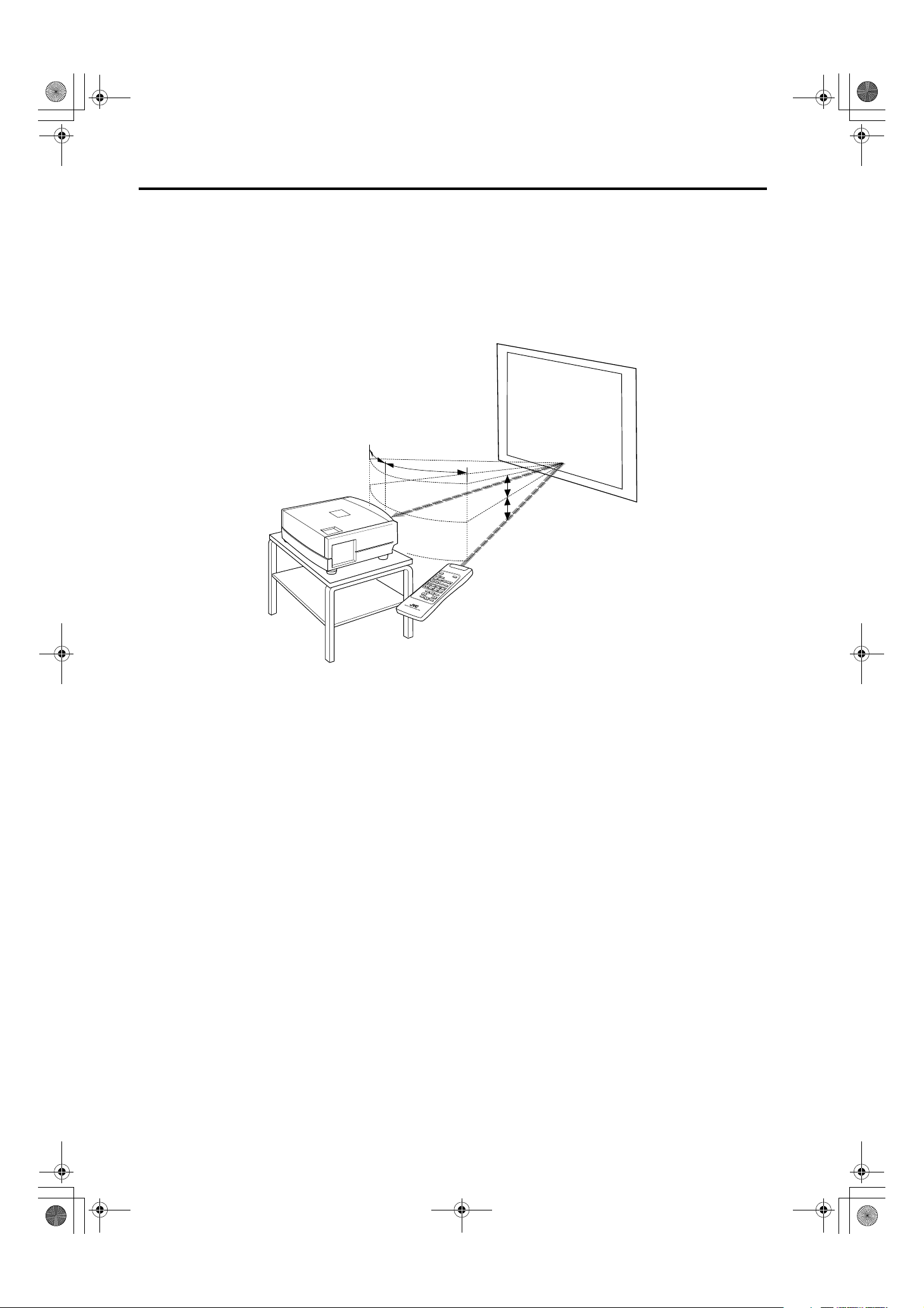
Effective Range and Distance of the Remote Control Unit
The remote control unit can be used as either a wireless remote control unit or a wired one.
Using as a wireless remote control unit
■
Aim the remote control unit toward the remote sensor on the front or the rear of the projector.
The operable distance of the remote control unit is about 10 m for direct reception. The remote control unit can be used by
having it reflected on the screen. In this case, the total distance of “A+B” should be about 10 m or less. The operable angles
of the remote control unit are 15° right and left, and 15° up and down.
Screen
Projector
15˚
15˚
A
15˚
15˚
B
Remote control unit
20
DLA-G150CLU&CLE_Eng.book Page 21 Thursday, February 21, 2002 2:39 PM
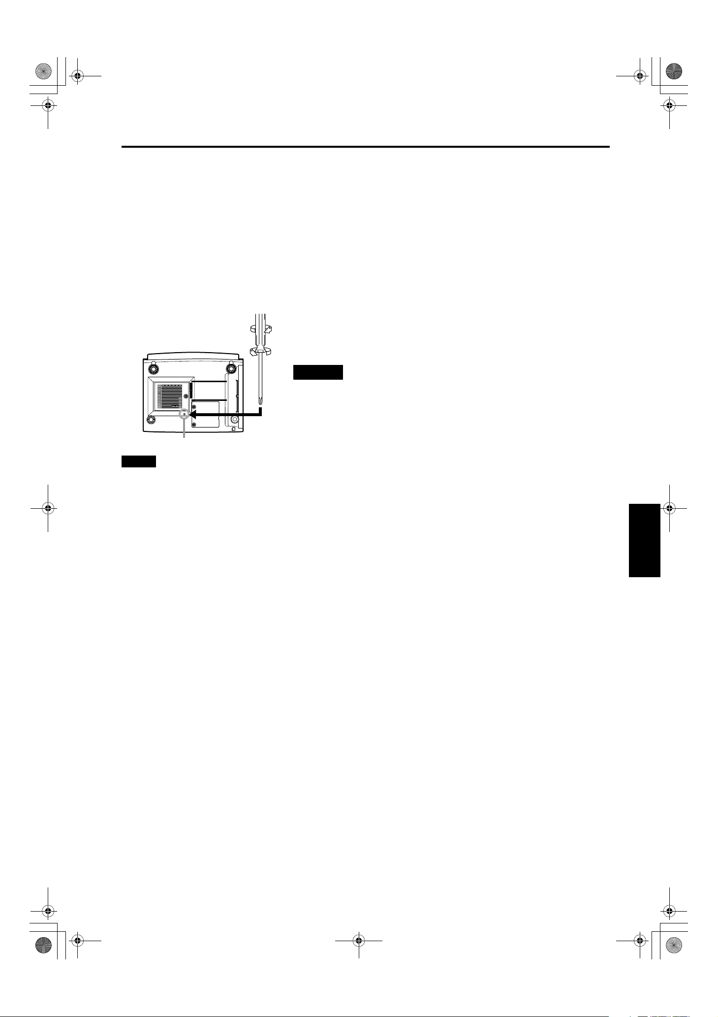
Setting the Position Selecting Screw for Ceiling Mounting
When using the projector in an upside-down, ceiling-mounted position (inverted top-to-bottom and right-to-left), the “position
selecting screw for ceiling mounting” must be turned to switch to ceiling mounting.
This will correct variance in color images (shading), which otherwise would occur in ceiling mounting.
To revert to normal desktop setting, turn the “position selecting screw for ceiling mounting” back to the initial position (factoryshipped).
When using the projector in an upside-down, ceiling-mounted position:
Turn the “position selecting screw for ceiling mounting” fully counterclockwise (until it is turning idly).
To again use the projector in a normal desktop setting:
Turn the “position selecting screw for ceiling mounting” fully clockwise (until it firmly tightens).
For normal desktop mounting:
Turn the screw clockwise.
For upside-down, ceiling-mounting:
Turn the screw counterclockwise.
DLA-G150CLU / LCT1123-001B / ENGLISH
Installing the Projector
CAUTIONS
•To ceiling-mount and adjust the projector, special expertise and technique are
necessary. Be sure to ask your dealer or a specialist to perform this work.
•To turn the “position selecting screw for ceiling mounting”, use a Phillips
screwdriver with a 30-mm or longer shank.
The screw is located in the hole shown in the illustration.
Position selecting screw for ceiling mounting
Note
• When using the projector in a ceiling-mounted position, you should reverse the projected image by changing the settings of
Right Left rev. and Top Bottom inv. menus. For details, refer to page 54. You can also change these settings without
receiving a video signal. In this case, refer to “Menu Transition Diagram in No signal Menu Mode” on page 38.
When installing (adjusting/setting) the unit
• When using “Top Bott o m inv. ” on the “Options” menu, reset the unit by following the procedure below.
• This reset procedure must be performed before operating the unit.
1. Change the “Top Bottom inv.” Setting on the “Options” menu.
2. Press the OPERATE button to enter the unit into the stand-by mode.
3. Press the OPERATE button again to turn on the unit.
• Adjust the focus after projecting a picture for 30 minutes or longer.
ENGLISHDEUTSHFRANÇAISITALIANOESPAÑOL
21
DLA-G150CLU&CLE_Eng.book Page 22 Thursday, February 21, 2002 2:39 PM
Connecting to Various Devices
Before connection, be sure to turn off the projector and connected devices.
Read the manual which comes with each device thoroughly.
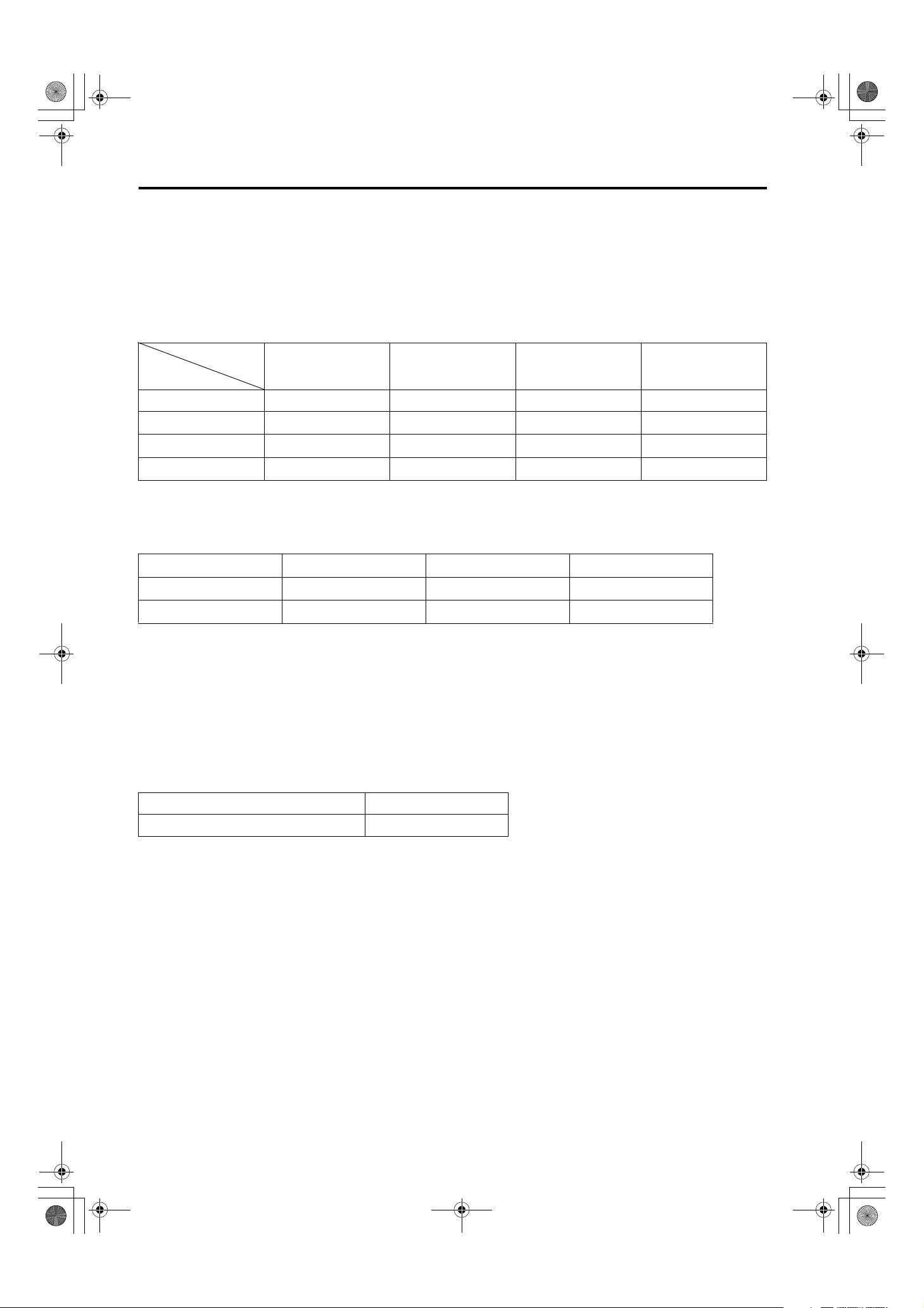
Signals that Can Be Input to the Projector
The following signals can be input to the projector:
■ Video signals
(1) Response to color systems
DLA-G150CLU / LCT1123-001B / ENGLISH
Color systems
NTSC NTSC4.43 PAL SECAM
Input terminal
VIDEO ‡‡‡‡
Y/C ‡
/B-Y, PR/R-Y ‡*
B
Y, P
G, B, R, H/CS, V ‡*
2
2
‡*
‡*
‡*
1
2
2
‡ - - - - -
2
‡*
‡*
2
‡*
‡*
2
2
*1:Responds if Y/C output is available.
, PR” / “Y, B-Y, R-Y” / “G, B, R, H/CS, V”) conform to the signal timing
*2:Signifies that component signals (“Y, P
B
(synchronization and video period) of each color system. The color systems are used for convenience only.
(2)
Response to double density (*3), high-vision signals
Input terminal
Y, P
/B-Y, PR/R-Y
B
G, B, R, H/CS, V
4
NTSC*
‡‡‡
‡‡‡
NTSC*
5
High-vision signal
*3:Signals whose density of scanning lines/field is twice as high.
*4:Responds to signals whose horizontal scanning frequency is 31.5 kHz. NTSC can be made twice as dense by a line
doubler (separately available: recommended article). Also, possible to respond to fully-specified, decoded
wide-clear-vision signal and decoded 525P progressive signal.
*5:Responds to signals whose horizontal scanning frequency is 33.5 kHz. PAL can be made twice as dense by a line doubler
(separately available: recommended article).
(3) Response to DTV-format signals
/B-Y, PR/R-Y, G, B, R, H/CS, V input terminal.
DTV-format signals (480i, 480p, 720p, 1080i) can be input to the Y, P
B
■ Computer signals
Signals with the following scanning frequencies can be input to the PC 1 or PC 2 (G, B, R, H/CS, V) and DVI terminals.
Horizontal scanning frequency 15kHz - 105kHz
Vertical scanning frequency 50Hz - 100Hz
Be sure that the computer to be used suffices the following conditions:
• The computer has the video signal output port.
Be sure that the computer has the video signal output port by reading the instruction book of the computer.
The video signal output port is generally called as “RGB port”, “monitor port”, or “video port”. If the computer-monitor hybrid
type or note type is used, it may need to prepare for an external output port. Also, there will be the type to which an external
output port cannot be installed.
• DVI input
During DVI input, depending on the computer settings, there may be no signal input or an error may occur (blue screen).
If this happens, turn off the power to both the projector and the computer, and then turn the projector back on before turning
the computer on again. Then correctly set the computer's graphic board.
• The resolution and the scanning frequencies are within the range specified in the table on page 23.
Be sure that the resolution and the scanning frequencies of the video signal are within the range. A video signal out of range
cannot be used. (Even signals out of the range could be projected. However, it may not sharp enough. On the other hand,
even some of the signals within the range may require adjustment depending on the video board used.)
When a signal other than listed in the table on page 23 is input, the image could be partially erased or an unneeded fold-over
image could appear.
Even signals in the frequency range that can be input may not be displayed normally depending on the type of the signal.
) and G on Sync signals cannot be handled depending on the devices connected.
Composite sync (C
S
22
DLA-G150CLU&CLE_Eng.book Page 23 Thursday, February 21, 2002 2:39 PM
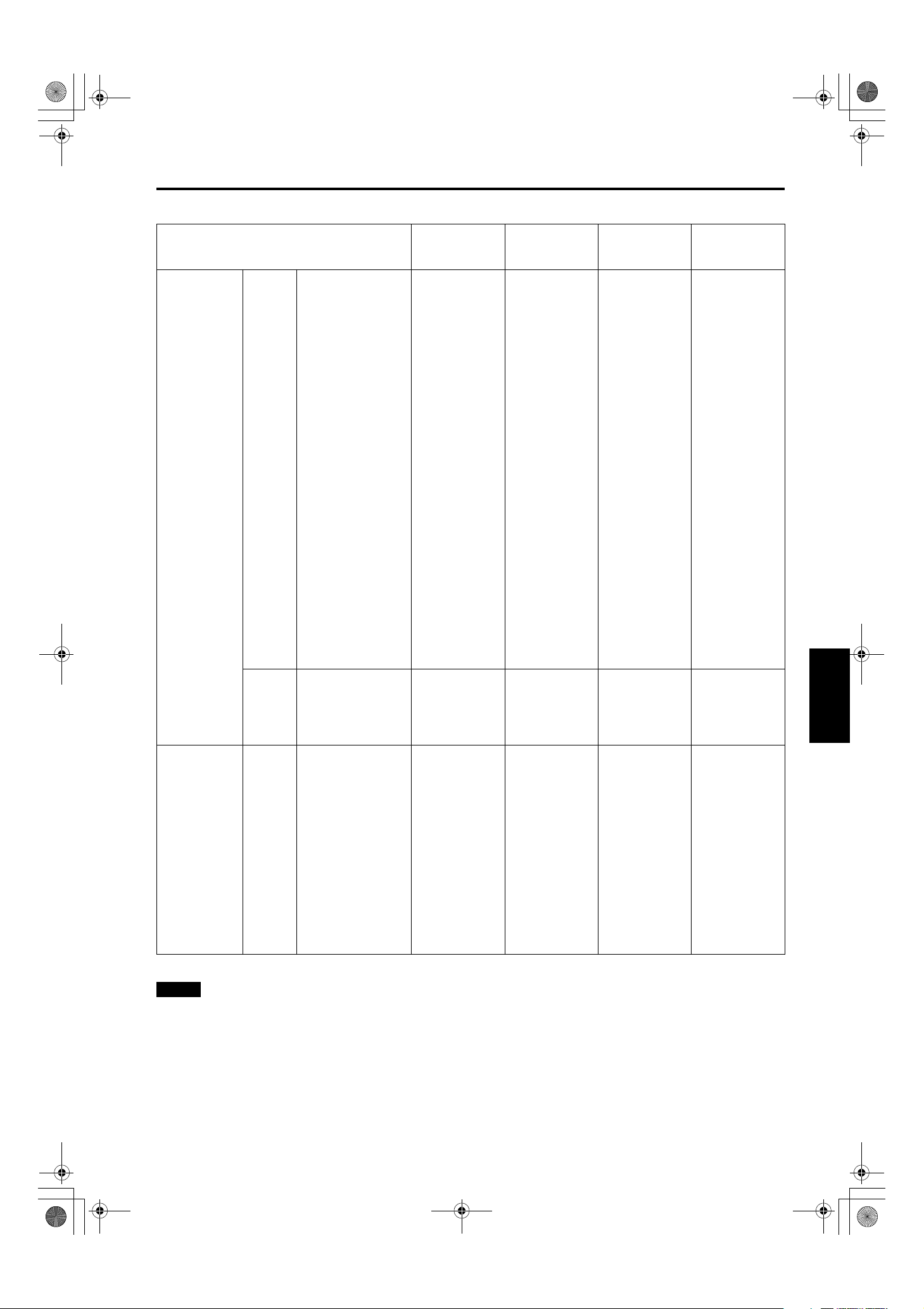
■ Allowable input signals
DLA-G150CLU / LCT1123-001B / ENGLISH
Connecting to Various Devices
Horizontal res-
Signal
PC system PC98 VESA350 640 350 37.86 84.13
PC/AT PC98 640 400 24.83 56.42
DOS/V VGA 60Hz* 640 480 31.47 59.94
DVI* VGA 72Hz* 640 480 37.86 72.81
VGA 75Hz* 640 480 37.50 75.00
VGA 85Hz* 640 480 43.27 85.01
SVGA 56Hz* 800 600 35.16 56.25
SVGA 60Hz* 800 600 37.88 60.32
SVGA 72Hz* 800 600 48.08 72.19
SVGA 75Hz* 800 600 46.88 75.00
SVGA 85Hz* 800 600 53.67 85.06
XGA 43Hz* 1024 768/2 35.52 43.48
XGA 60Hz* 1024 768 48.36 60.00
XGA 70Hz* 1024 768 56.48 70.07
XGA 75Hz* 1024 768 60.02 75.03
XGA 85Hz* 1024 768 68.68 85.00
SXGA 43Hz* 1280 1024/2 46.43 43.44
SXGA 60Hz* 1280 1024 63.98 60.02
SXGA 75Hz* 1280 1024 79.98 75.03
SXGA 85Hz* 1280 1024 91.15 85.02
UXGA 60Hz 1600 1200 75.00 60.00
Mac MAC13 640 480 35.00 66.67
MAC16 832 624 49.73 74.55
MAC19 1024 768 60.24 74.93
MAC21 1152 870 68.68 75.06
Video system Video HDTV (1035i) 60Hz 33.75 60.00
HDTV (1035i) 59Hz 33.72 59.94
480p 720 483 31.47 59.94
720p 60Hz 1280 720 45.00 60.00
720p 59Hz 1280 720 44.96 59.94
1080i 60Hz 1920 1080/2 33.75 60.00
1080i 59Hz 1920 1080/2 33.72 59.94
1080 24sF 1920 1080 27.00 24.00
NTSC 15.734 60
PAL 15.625 50
SECAM 15.625 50
olution
Hor [Pixels]
Vertical resolu-
tion
Ver [Lines]
Horizontal fre-
quency
H [kHz]
Vertical fre-
quency
V [Hz]
ENGLISHDEUTSHFRANÇAISITALIANOESPAÑOL
* A signal that can be input by DVI (V-sync 85Hz is not supported.)
Notes
• The resolution for the input signals is listed in the above table.
• Even signals in the frequency range that can be input may not be displayed normally depending on the type of the signal.
• When a signal other than listed above is input, the image could be partially erased or an unneeded fold-over image could
appear.
• Some signals other than listed above can be displayed. But they may require adjustment.
• Even some of the signals listed above may require adjustment depending on the video board used.
) and G on Sync signals cannot be handled depending on the devices connected.
• Composite sync (C
• The VGA signal of the PC system could be displayed in 480p mode of the VIDEO system. (In this case, the projector enters
video menu mode when the MENU button is pressed.)
S
23
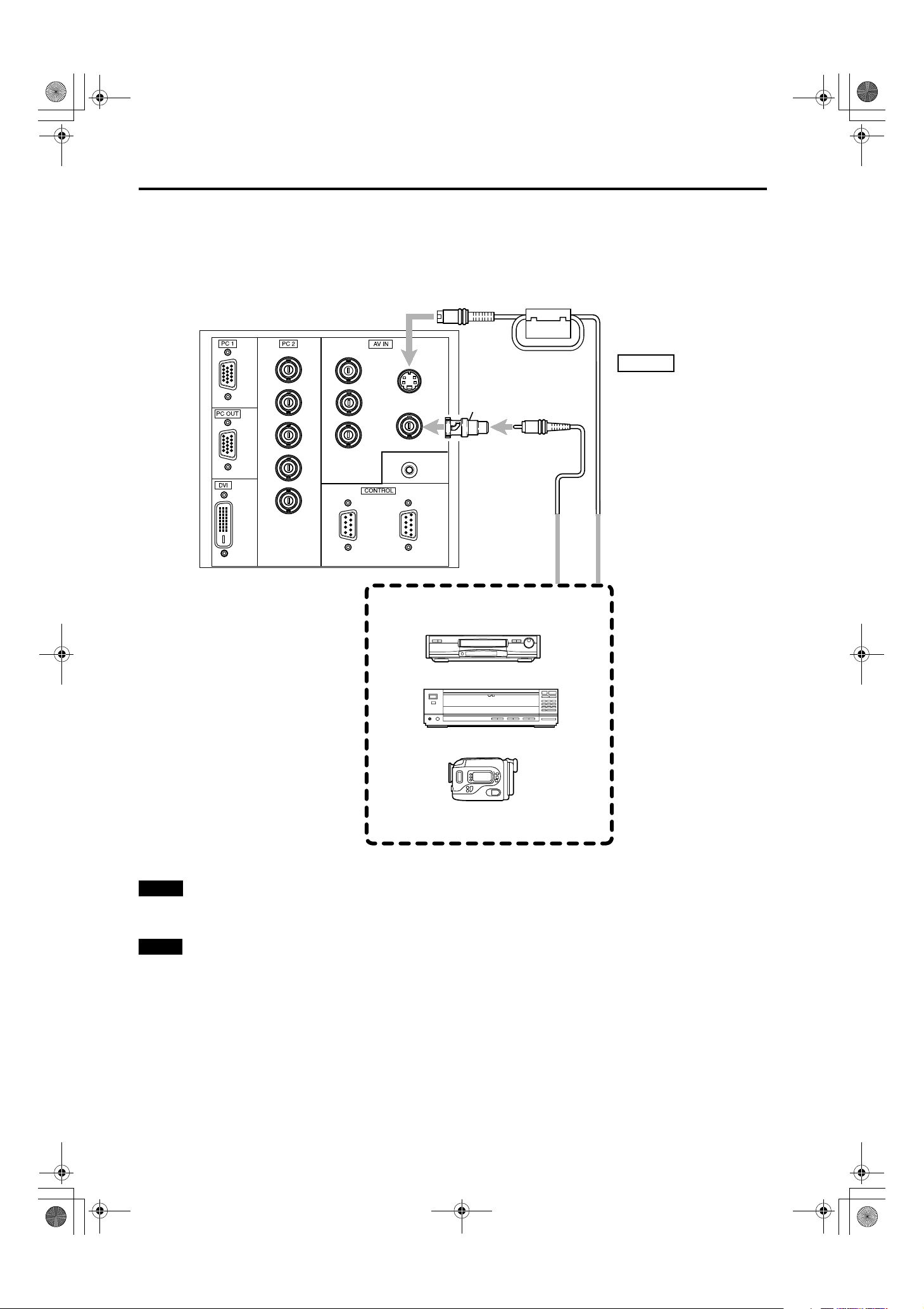
DLA-G150CLU&CLE_Eng.book Page 24 Thursday, February 21, 2002 2:39 PM
Connecting to Various Devices
Connecting to Video Devices
Before connection, be sure to turn off both the projector and video device.
• Read thoroughly the manual that comes with each video device.
• Use the supplied video cable. An video cable with an S-video (Y/C) terminal is not supplied.
DLA-G150CLU / LCT1123-001B / ENGLISH
R
G
B
H
V
IN
Y
P
B/B-Y
P
R/R-Y
REMOTE
IN OUT
Y/C
VIDEO
BNC-RCA conversion
plug (accessory)
To VIDEO
Video cable
To AV IN
To Y/C
S-video cable
(separately available)
(accessory)
Video devices
• VCR (Video cassette recorder)
• Laser videodisc player
• Camcorder
Notes
• Connect a composite image signal output device or Y/C (S-video) image output device.
• When connecting the S-video cable, refer to “How to attach the ferrite core” on page 29.
Memo
• When connecting a video device, use a TBC along with it, or one which has a built-in TBC.
• Use of an extension cable to connect a video device and the projector could cause video degradation.
• When a signal with much jitter is reproduced on a VCR, or special-effect playback is performed, the upper part of the image
or the image itself may be erased or distorted.
24
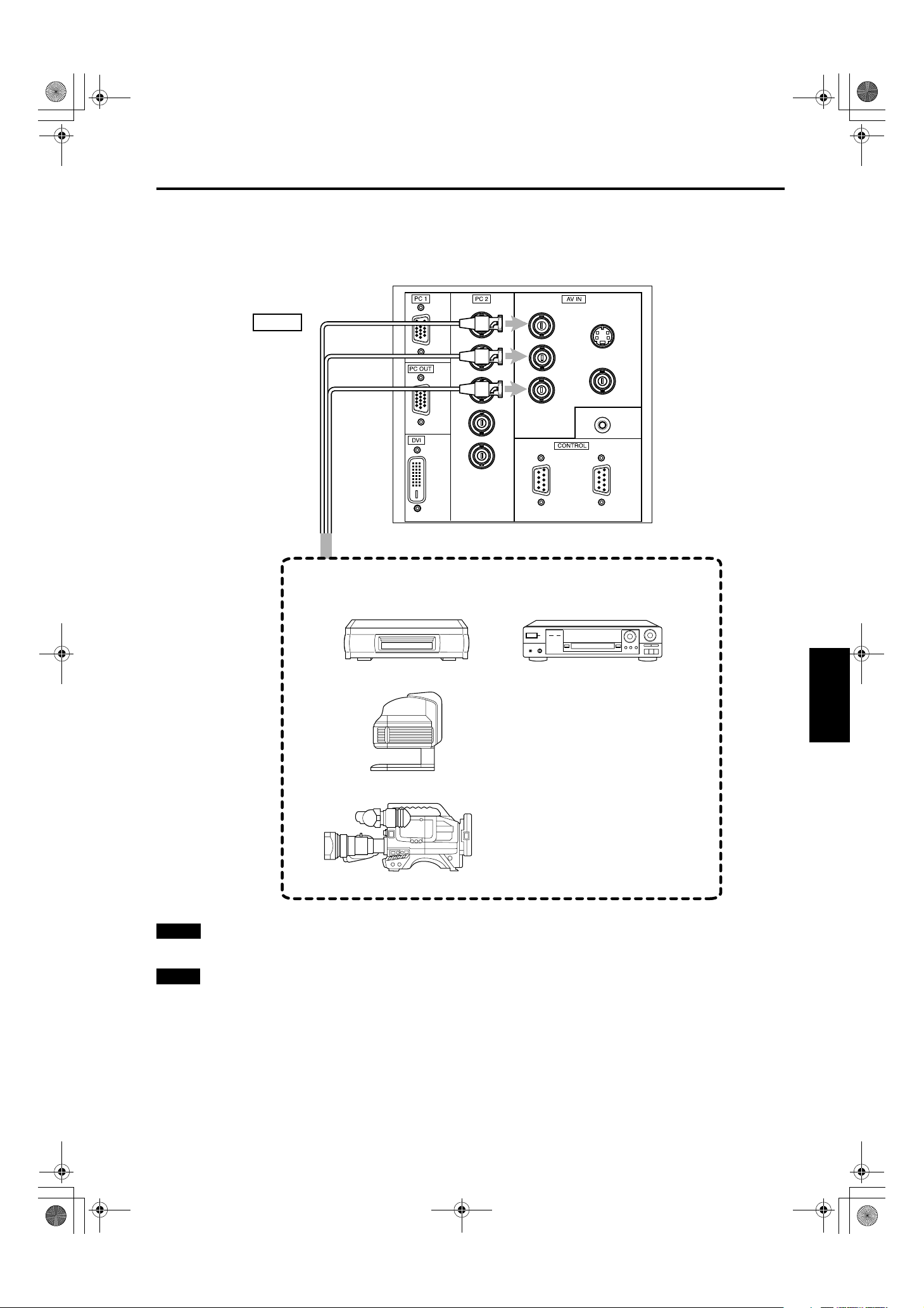
DLA-G150CLU&CLE_Eng.book Page 25 Thursday, February 21, 2002 2:39 PM
Connecting to Hi-Vision Devices/DVD Players
Before connecting, be sure to turn off both the projector and Hi-Vision devices/DVD players.
• Thoroughly read the manual that comes with each Hi-Vision device or DVD player.
• Use separately available BNC cables to connect Hi-Vision devices and DVD players.
To Y
To PC 2
To PB/B-Y
To P
R/R-Y
DLA-G150CLU / LCT1123-001B / ENGLISH
Connecting to Various Devices
R
G
B
Y
P
P
B/B-Y
R/R-Y
Y/C
VIDEO
BNC cable
(separately available)
Hi-Vision devices
• W-VHS VCR
• Text/video camera
H
REMOTE
V
IN
IN OUT
DVD player
ENGLISHDEUTSHFRANÇAISITALIANOESPAÑOL
• Hi-Vision video camera
Note
• Connect a component signal output device or DTV-format signal output device.
Memo
• Other devices with component signal output terminals (DVD player (NTSC), etc.) can be connected.
(*DVD: Digital Video Disc)
• DTV-format signals (480i, 480p, 720p, 1080i) can be input. For DTV-format signals which can be handled, refer to “Video
signals” on page 22.
25
DLA-G150CLU / LCT1123-001B / ENGLISH
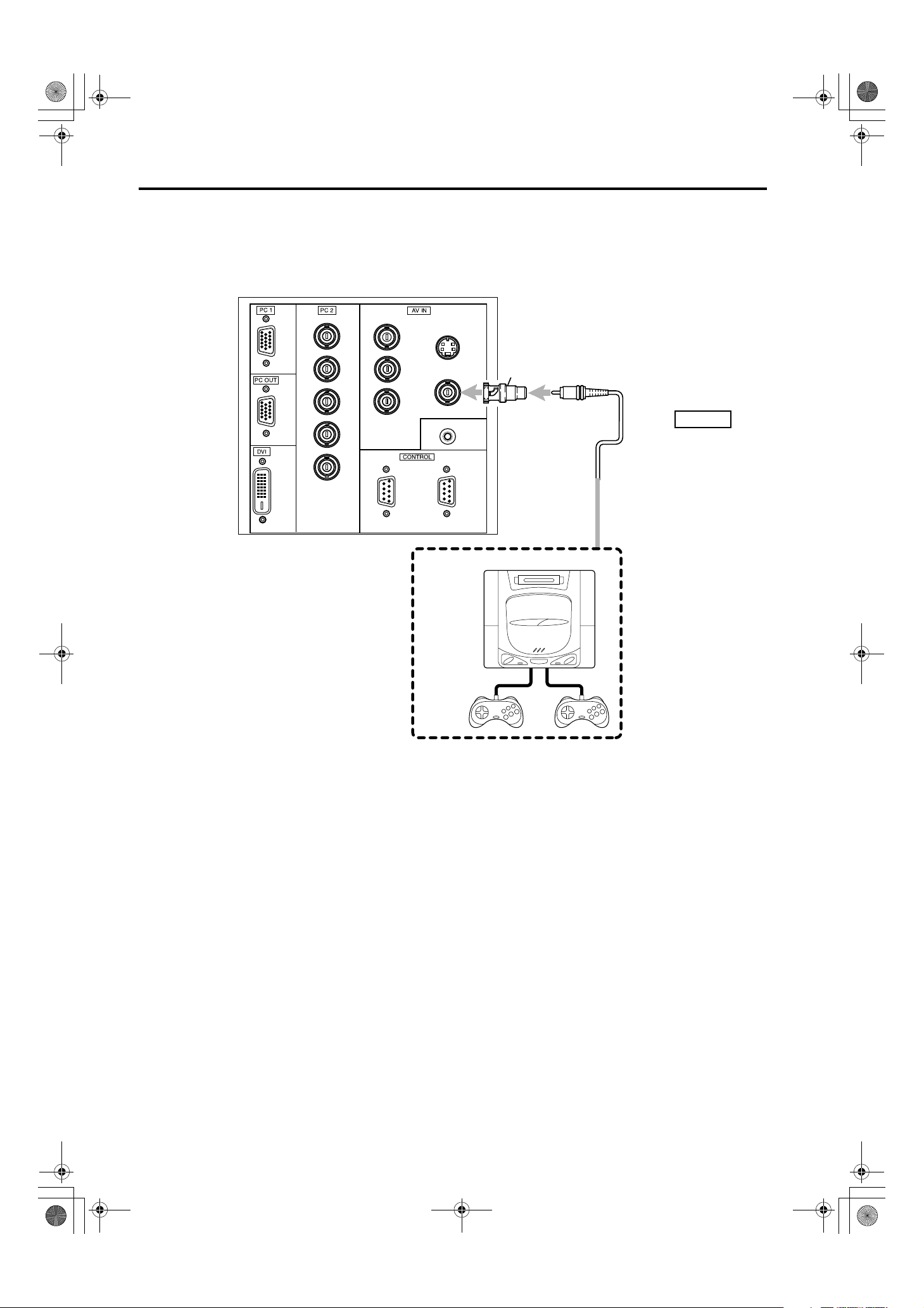
DLA-G150CLU&CLE_Eng.book Page 26 Thursday, February 21, 2002 2:39 PM
Connecting to Various Devices
Connecting to Other Devices
Before connection, be sure to turn off both the projector and other devices to be connected.
• Read thoroughly the manual that comes with the device to be connected.
• Use the supplied video cable or the cable supplied with the game device.
R
G
B
H
V
IN
Y
P
P
B/B-Y
R/R-Y
REMOTE
Y/C
BNC-RCA conversion
plug (accessory)
VIDEO
To VIDEO
To AV IN
Cable supplied with the
IN OUT
game device, or supplied
video cable
Game device, etc.
26
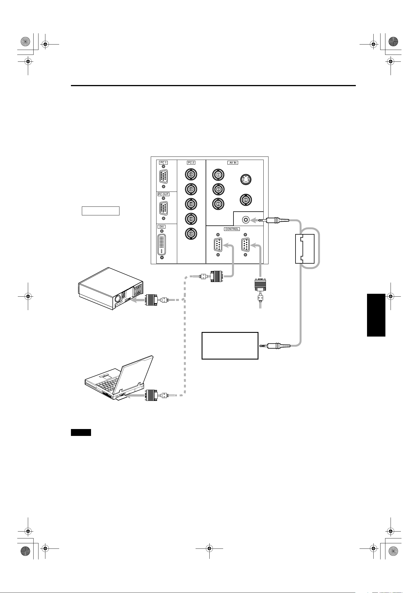
DLA-G150CLU&CLE_Eng.book Page 27 Thursday, February 21, 2002 2:39 PM
Connecting to Devices which Control the Projector
Before connection, be sure to turn off both the projector and devices to be connected.
• Read thoroughly the manual that comes with each device to be connected.
• By connecting a computer to the RS-232C terminal, you can control the projector. Also, you can make an infrared remote
sensor extension unit and connect it to the REMOTE terminal of the projector.
* Obtain connection cables as required. Use a reverse connection cable.
* For details, refer to “RS-232C external control” on page 74.
* For further details, consult your dealer or an authorized service center.
DLA-G150CLU / LCT1123-001B / ENGLISH
Connecting to Various Devices
TO CONTROL
• Desktop type
IN
To RS-232C connector
R
G
B
H
V
Y
B/B-Y
P
P
R/R-Y
IN OUT
To RS-232C connector
Y/C
VIDEO
REMOTE
*
To REMOTE terminal
ENGLISHDEUTSHFRANÇAISITALIANOESPAÑOL
Infrared remote sensor
• Note type
extension unit
(Needs to be made)
RS-232C reverse
connection cable
(separately available)
* By directly connecting the OUT terminal
to the second DLA-G150CLU IN
To RS-232C connector
terminal, a number of DLA-G150CLU
units can be controlled by a single
computer.
Note
• When connecting the cable to the REMOTE terminal, refer to “How to attach the ferrite core” on page 29.
27
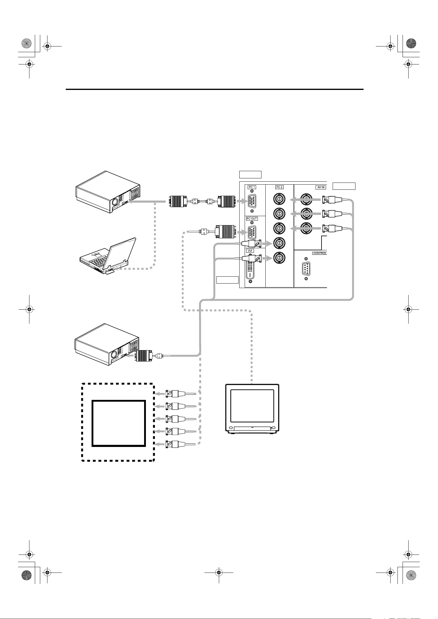
DLA-G150CLU&CLE_Eng.book Page 28 Thursday, February 21, 2002 2:39 PM
Connecting to Various Devices
Connecting to Computer Devices
Before connection, be sure to turn off both the projector and computer devices.
• Read thoroughly the manual that comes with each device.
■ Connection to an IBM PC or IBM-compatible computer
• Use the supplied personal computer connection cable. Also, prepare cables required for connecting the devices
connected.
• Desktop type
To PC 1
To monitor
connector
• Notebook type
* There are some notebook types which
do not allow the computer’s LCD to work
if an external display is connected. With
such a notebook computer, the LCD
display and external display output
need to be switched.
Personal Computer
connection cable (supplied)
To PC 1
To PC OUT
Cable
supplied
with the
To H/Cs
display (or
separately
available)
To V
(D-sub 3row 15-pin)
To PC 2
To PC 2
Separate cable (separately available)
DLA-G150CLU / LCT1123-001B / ENGLISH
To P C 2
R
G
B
H
V
IN
Y
P
B/B-Y
P
R/R-Y
IN
To R
To G
To B
• Desktop type
• RGB output devices
Laser video disc
player, etc.
To monitor connector
To R
To G
To B
POWER
To H/Cs
Display monitor
To V
* When a display monitor is connected to
the PC OUT terminal, you can view the
video from the computer on the monitor.
28

Y
P
P
DLA-G150CLU&CLE_Eng.book Page 29 Thursday, February 21, 2002 2:39 PM
Connecting to DVI
Before connection, be sure to turn off both the projector and computer devices.
• Read thoroughly the manual that comes with each device.
DLA-G150CLU / LCT1123-001B / ENGLISH
Connecting to Various Devices
R
G
B
H
DOS/V
(DVI VIDEO BOARD)
Note
• Other connections are the same as in the connection example for IBM PC or IBM compatible PCs.
DVI (DVI-D 24pin Cable)
(Available separately)
IN
V
IN
How to attach the ferrite core
Attach the ferrite core when using the S-video cable or infrared remote sensor extension unit which are sold separately.
However, use a cable that can be wound once.
Release the stopper at each end and
1
open the ferrite core.
Stoppers
Wind the cord around the ferrite core.
2
Attach the ferrite core about 3 cm from the end of the
cord.
Wind the cable once.
ENGLISHDEUTSHFRANÇAISITALIANOESPAÑOL
Close the ferrite core with the cord
3
inside until you hear it click shut.
Note
• When connecting, connect the terminal which is at the
ferrite core end of the cord to the projector.
Click!
29

DLA-G150CLU / LCT1123-001B / ENGLISH
DLA-G150CLU&CLE_Eng.book Page 30 Thursday, February 21, 2002 2:39 PM
Connecting to Various Devices
Connecting the Power Cord
After all devices have been finished being connected, connect the supplied power cord. At this time, do not yet turn on the
MAIN POWER switch.
Insert the supplied power cord into the
R
E
T
N
E
U
N
E
O
M
E
D
I
V
C
P
T
I
X
E
E
T
A
R
E
P
O
T
E
S
E
E
R
P
N
O
T
E
S
ID
Y
P
E
H
M
K
E
PT
M
A
L
N
W
O
D
P
U
Power cord (supplied)
1
power input terminal of the projector.
Insert the main plug of the supplied
2
power cord into a suitable wall outlet.
Ferrite core
CAUTIONS
To prevent fire and electric shock, observe the
following:
• When you do not use devices, pull out their power cords
from wall outlets.
• Do not connect the devices with power cords other than
those supplied.
• Do not use mains voltage other than the power voltage
indicated.
• Do not scar, damage, or work on the power cords. Also, do
not put a heavy object on, heat, or stretch the power cords,
otherwise they may be damaged.
• Do not insert or pull out the plugs with a wet hand.
Removing the Lens Cap
Remove the lens cap before using the projector.
Notes
• The lens cap is supplied with the lens unit (optional). It
should be attached to the lens when the projector is not
used.
• Do not operate the projector with the lens cap attached.
Doing so can deform the lens cap because of the heat. A
metallic lens cap can get hot and cause injury.
CAUTIONS
• Since the power requirement of the projector is high, insert
for European
for United Kingdom
continent countries
the power plug directly into a wall outlet.
• Use the supplied power cord with the ferrite core only.
• Do not remove the ferrite core from the supplied power
cord; Otherwise, there may be a possibility that a harmful
interference occurs.
30

DLA-G150CLU&CLE_Eng.book Page 31 Thursday, February 21, 2002 2:39 PM
Basic Operations
■ Lamp control settings
After turning the power on, first perform the lamp control settings on the setting menu referring to “Setting and Adjusting Other
Functions (OPTIONS)” on page 54.
There are 3 modes in the lamp control settings.
1: NORMAL MODE (Normal)
Used as a normal lamp.
The projector is set to “Normal” mode at the time of purchase.
* “Lamp replacement” appears on the screen when the lamp use time exceeds 1000 hours.
2: LIGHT POWER CONTROL MODE (LPC)
Automatically controls the power used by the lamp and increases it in steps. When this mode is used, the brightness
starts at approximately 70%. The decrease in brightness is slower than in “Normal” mode and this mode is best suited
when using the projector continuously for long periods of time.
* “Lamp replacement” appears on the screen when the lamp use time exceeds 2000 hours.
3: LIGHT OUTPUT CONTROL MODE (LOC)
The brightness can be set in seven levels (-6 to 0). Since the brightness can be set in steps, this is the mode best suited
for adjusting multiple screens. This setting can also be changed while the projector is being used. To change the setting,
choose LOC with the 5/∞ cursors and choose the level with the 2/3 cursors.
* “Lamp replacement” appears on the screen when the lamp use time exceeds 2000 hours.
DLA-G150CLU / LCT1123-001B / ENGLISH
The lamp replacement time is different for the 3 modes.
1: NORMAL MODE (Normal) ... 1000 hours
2: LIGHT POWER CONTROL MODE (LPC) ... 2000 hours
3: LIGHT OUTPUT CONTROL MODE (LOC) ... 2000 hours
* These lamp replacement times are only a rough guide as to how long the lamp will last if these modes are used from the
beginning. These are not guaranteed service lives.
Notes
• Although the LIGHT OUTPUT CONTROL MODE (LOC) and LIGHT POWER CONTROL MODE (LPC) electrically control
the brightness of the lamp and extend the replacement time longer than that for the NORMAL MODE, the service life of the
lamp is approximately 1000 hours.
• The lamp will gradually become less bright in each mode.
Since the lamp may become less bright quickly in some usage environments, replace the lamp if you notice that it is no
longer bright even if the lamp has not yet reached the end of its life.
• Mode settings
* If the projector is not put in stand-by mode or turned off after the lamp has been used continuously in the normal mode for
more than 1000 hours (but less than 2010 hours), it can be used for “up to 2010 hours”.
However, if the projector is put in stand-by mode or turned off, it can not be turned back on again.
* If the projector is put in stand-by mode or turned off after the lamp has been used in the light output control mode or light
power control mode for more than 2000 hours (but less than 2010 hours), it can not be turned back on again.
However, if the projector is not put in stand-by mode or turned off, it can be used for “up to 2010 hours”.
* If the projector is used in the light output control mode or light power control mode for more than 1000 hours, and then
switched to the normal mode, put in stand-by mode or turned off, it can not be turned back on again.
After performing the above settings, perform the necessary settings.
ENGLISHDEUTSHFRANÇAISITALIANOESPAÑOL
31

DLA-G150CLU&CLE_Eng.book Page 32 Thursday, February 21, 2002 2:39 PM
Basic Operations
DLA-G150CLU / LCT1123-001B / ENGLISH
■ Projector’s buttons
LAMP TEMP
HIDE
KEYSTONE
PRESET
EXIT ENTER
N
W
O
D
STAND BY
OPERATE
PC
VIDEO
MENU
R
TE
N
E
U
O
MEN
E
ID
V
C
P
T
XI
E
E
AT
ER
OP
T
SE
E
RE
P
N
O
T
E
ID
YS
P
H
KE
EM
T
P
AM
L
P
U
STAND BY indicator
OPERATE indicator
OPERATE button
The following describes the basic procedure for normal use
of the projector.
1. Turning on the Power
Turn on the MAIN POWER switch.
1
ON [ ❙❙❙❙ ]:The main power turns on and the STAND BY
indicator comes on.
Projector’s indicator
STAND BY
OPERATE
Press the OPERATE button for one
2
second or more.
• The OPERATE indicator lights and the projected
screen slowly appears.
Remote control unit
OPERATE
or
Projector
STAND BY
OPERATE
Notes
• After the power is turned on, the image may be jumbled for
a few seconds, but this is not a malfunction.
• After the indicator comes on, it can take a minute or so for
the lamp to warm up and operate consistently.
■ Turning off the Power
■ Remote control unit
QUICK
ALIGN.
W
W
SCREEN
SCREEN
S
S
PC1 PC2
KEYSTONE
HIDE
FREEZE
COMP
DVI
T
T
DIGITAL
ZOOM FOCUS
ZOOM
W
W
PRESET
RM-M160 REMOTE CONTROL UNIT
OPERATE
VIDEO
Y/C
MENU
ENTEREXIT
OPERATE button
Press the OPERATE button for one
1
second or more.
• The STAND BY indicator changes to blinking, and the
projector goes into cool-down mode. The cool-down
mode will continue for approximately 120 seconds.
Remote control unit
OPERATE
Projector
STAND BY
OPERATE
(Blinking)
Note
• The OPERATE button will not work for approximately 1
minute from when the light-source lamp is turned on. Use
the button after approximately 1 minute.
Turn off the MAIN POWER switch after
2
the STAND BY indicator changes to
steady on.
OFF [‡‡‡‡]:The MAIN POWER switch turns off and the
STAND BY indicator goes off.
Projector
STAND BY
OPERATE
32
CAUTION
• Do not turn off the MAIN POWER switch during cool-down
mode (the STAND BY indicator blinking). Turn it off after
the STAND BY indicator becomes on (stand-by mode).

DLA-G150CLU&CLE_Eng.book Page 33 Thursday, February 21, 2002 2:39 PM
DLA-G150CLU / LCT1123-001B / ENGLISH
Basic Operations
■ Projector’s buttons
LAMP TEMP
HIDE
KEYSTONE
PRESET
EXIT ENTER
STAND BY
OPERATE
PC
VIDEO
MENU
PC button
VIDEO button
■ Remote control unit
QUICK
ALIGN.
W
W
SCREEN
SCREEN
S
S
PC1 PC2
KEYSTONE
HIDE
FREEZE
COMP
DVI
T
T
DIGITAL
ZOOM FOCUS
ZOOM
W
W
PRESET
RM-M160 REMOTE CONTROL UNIT
OPERATE
VIDEO
MENU
ENTEREXIT
Y/C
PC button
VIDEO button
ZOOM button
■ Language display
The display languages of the menus, direct buttons
(DIGITAL ZOOM, KEYSTONE, etc) and messages is set to
“ENGLISH” when the projector is bought. The display
language can be selected from the following 6 languages:
“ (Japanese)”, “English (English)”, “Deutsch
(German)”, “Español (Spanish)”, “Italiano (Italian)” and
“Français (French)”. (Refer to page 46.) However, some
words (VIDEO, NTSC, Quick Alignment, etc) are only
displayed in English.
2. Select the Input source to be Projected
Press the VIDEO button or the PC button to switch the input.
• Each time you press either button, the selected input
changes as follows. The selected name appears on the top
right of the image on the screen for five seconds. (Called
line display.)
When selecting an image device connected to the
AV IN (VIDEO, Y/C or COMP) terminal:
Projector
Press VIDEO.
The input mode changes as follows every time the button is
pressed.
VIDEO ↔ Y/C ↔ COMP
Remote control unit
Press the “VIDEO”, “Y/C” or “COMP” button.
VIDEO: The image from the VIDEO input terminal on the
side of the unit is projected.
Y/C: The image from the Y/C input terminal on the side of
the unit is projected.
/B-Y, PR/R-Y)
COMP: The image from the COMP (Y, R
input terminal on the side of the unit is projected.
* When there is no signal from the selected input terminal
(No signal), “No Input” is displayed.
When selecting a device such as a computer
which is connected to the PC1, PC2 or DVI
terminal:
Projector
Press PC.
The input mode changes as follows every time the button is
pressed.
PC1 ↔ PC2 ↔ DVI
Remote control unit
Press the “PC1”, “PC2” or “DVI” button.
PC1: The image from the PC1 input terminal on the side of
the unit is projected.
PC2: The image from the PC2 input terminal on the side of
the unit is projected.
DVI: The image from the DVI input terminal on the side of
the unit is projected.
* When there is no signal from the selected input terminal
(No signal), “No Input” is displayed.
Remote control unit Projector
SCREENSSCREEN
FREEZE
COMP
S
PC1 PC2
VIDEO
DVI
Y/C
B
PC
VIDEO
ENGLISHDEUTSHFRANÇAISITALIANOESPAÑOL
[Screen display]
VIDEO
QUICK ALIGNMENT
Line Display
PC 1
PC 2
Y/C
VIDEO
COMP
DVI
* To show the line display (Y/C, VIDEO, COMP, PC1, PC2 or
DVI) or not is selectable by the menu. Refer to “Setting and
Adjusting Other Functions (OPTIONS)” on page 54.
Note
• When no image signal is input to the selected input
terminal, the message “No Input” is displayed on the
screen. (Refer to page 67.)
33

DLA-G150CLU&CLE_Eng.book Page 34 Thursday, February 21, 2002 2:39 PM
Basic Operations
DLA-G150CLU / LCT1123-001B / ENGLISH
■ Projector’s buttons
LAMP TEMP
KEYSTONE
PRESET
PRESET button
EXIT button
EXIT ENTER
■ Remote control unit
QUICK
ALIGN.
W
SCREEN W/S button
FOCUS +/– button
ZOOM T/W button
PRESET button
EXIT button
W
SCREEN
SCREEN
S
S
PC1 PC2
KEYSTONE
HIDE
HIDE
FREEZE
COMP
DVI
T
T
DIGITAL
ZOOM FOCUS
ZOOM
W
W
PRESET
RM-M160 REMOTE CONTROL UNIT
OPERATE
VIDEO
MENU
ENTEREXIT
STAND BY
OPERATE
VIDEO
MENU
Y/C
3. Adjust the Screen Size (Zooming)
How to adjust the projected screen size differs depending on
the lens unit (optional) you are using.
GL-M2910G (without zooming function):
PC
The projected screen size cannot be changed.
GL-M2915SG/GL-M2920ZG/GL-M2930SZG (with
zooming function):
Adjust the projected screen size with the following buttons on
the remote control unit.
Note
• The function of GL-M2915SG is to adjust the view angle
zooming by 2%. (For fine view angle adjustment)
To enlarge the projected screen size
Press the ZOOM W (Wide) button.
To reduce the screen size
Press the ZOOM T (Tele) button.
Remote control unit
T
DIGITAL
ZOOM
W
4. Adjust Focus
Adjust focus with the following buttons on the remote control unit.
To focus on farther points:
Press the FOCUS + button.
To focus on nearer points:
Press the FOCUS – button.
Remote control unit
FOCUS
5. Setting the Screen Aspect Ratio
Set in accordance with the screen aspect ratio that will be
used. When a screen aspect ratio of 16:9 is used, a 4:3
image can be projected within the screen without using the
zoom function.
When using a 16:9 screen:
Press the “W” button.
When using a 4:3 screen:
Press the “S” button.
Remote control unit
* There is no button on the unit.
* This setting can also be performed from the menu. (Refer
to page 46.)
• When using a screen with a 16:9 aspect ratio
When set to “S” (4:3)
* If a 4:3 image is projected, some
parts of the top and bottom of the
image may not be displayed.
When set to “W” (16:9)
* A 4:3 image will be displayed in full
in the middle of the screen.
W
W
SCREEN
SCREEN
S
S
34

DLA-G150CLU&CLE_Eng.book Page 35 Thursday, February 21, 2002 2:39 PM
DLA-G150CLU / LCT1123-001B / ENGLISH
Basic Operations
■ Projector’s buttons
LAMP TEMP
HIDE
HIDE
button
KEYSTONE
/ buttons
KEYSTONE
PRESET
PRESET
button
EXIT
button
EXIT ENTER
■ Remote control unit
HIDE button
KEYSTONE
/ buttons
PRESET button
EXIT button
QUICK
ALIGN.
W
W
SCREEN
SCREEN
S
S
PC1 PC2
KEYSTONE
HIDE
FREEZE
COMP
DVI
T
T
DIGITAL
ZOOM FOCUS
ZOOM
W
W
PRESET
RM-M160 REMOTE CONTROL UNIT
STAND BY
OPERATE
PC
VIDEO
MENU
OPERATE
VIDEO
Y/C
MENU
ENTEREXIT
Turning off Image (HIDE)
Video image can be temporarily turned off.
Press the HIDE button once:
Video image instantly turn off.
Press the HIDE button again:
Video image come on again.
Remote control unit
HIDE
Note
• When the projected image input is changed, the HIDE
function is canceled and the image return.
Projector
HIDE
Removing the Trapezoidal Distortion of
the Image
If the image projected on the screen is distorted in trapezoid
form, correct it with the KEYSTONE buttons on the projector.
When the KEYSTONE button is pressed, “Keystone”
appears on the screen together with the level bar and set
value (–80 to 128). When “15 sec.” is displayed in the menu,
“Keystone” will appear in approximately 15 seconds.
Keystone 123
When you press the KEYSTONE button:
The trapezoid form is corrected as shown in the figure.
When you press the KEYSTONE button:
The top bottom inverted trapezoid form is corrected as
shown in the figure.
* To cancel correction and restore the original screen, press
the PRESET button.
* Press the EXIT button to immediately remove the keystone
display.
Remote control unit Projector
(Adjusted value:0)
ENGLISHDEUTSHFRANÇAISITALIANOESPAÑOL
KEYSTONE
KEYSTONE
Projected image with trapezoidal distortion
KEYSTONE
KEYSTONE
Notes
• The trapezoidal distortion (keystone) can be adjusted from
the option menu. (Refer to page 54.)
• The range of the trapezoidal distortion adjustment is
approximately 20° in the vertical direction.
• Interference patterns may appear on the screen when
adjusting the keystone. This is not a malfunction.
• Depending on the type of signal, some noise may appear in
the picture when the keystone is adjusted.
This is not a malfunction.
35

DLA-G150CLU&CLE_Eng.book Page 36 Thursday, February 21, 2002 2:39 PM
Basic Operations
DLA-G150CLU / LCT1123-001B / ENGLISH
■ Remote control unit
QUICK
QUICK ALIGN.
button
ALIGN.
W
W
SCREEN
SCREEN
S
S
PC1 PC2
KEYSTONE
RM-M160 REMOTE CONTROL UNIT
HIDE
FREEZE
DIGITAL
ZOOM
PRESET
T
W
OPERATE
COMP
DVI
T
ZOOM FOCUS
W
ENTEREXIT
VIDEO
MENU
Quick Alignment Function
(QUICK ALIGN.)
The Quick Alignment function automatically adjusts (sets)
the screen settings of the image input from the PC1, PC2 or
DVI input terminals. This can only be performed from the
remote control.
Y/C
While projecting an image on the screen, press the QUICK
ALIGN. button on the remote control.
Quick alignment is conducted to obtain best image.
* During the automatic alignment, “Quick Alignment” appears
on the screen, and then disappears when the alignment is
completed.
Remote control unit
QUICK
ALIGN.
[Screen display]
Quick Alignment
Notes
• This only works for the signals input from the PC1, PC2 or
DVI input terminals. It does not work for the signals input
from the AV IN terminal (VIDEO, Y/C or COMP input
terminal).
• The quick alignment function is used to automatically adjust
the “Horizontal and vertical position”, “Phase” and
“Tracking” of the projected image.
• When using the quick alignment function to automatically
adjust the image, use a bright, still-picture. It may not
function correctly on a dark or motion picture. If the results
obtained with the quick alignment function are not
satisfactory, manually adjust the “Horizontal and vertical
position”, “Phase” and “Tracking” of the projected image.
36

Eng_Body.fm Page 37 Wednesday, May 15, 2002 10:17 AM
DLA-G150CLU / LCT1123-001C / ENGLISH
Basic Operations
■ Remote control unit
QUICK
ALIGN.
HIDE
W
W
SCREEN
SCREEN
FREEZE
S
S
DIGITAL ZOOM
T/W button
PRESET button
EXIT button
FREEZE message
PC1 PC2
DIGITAL
KEYSTONE
PRESET
RM-M160 REMOTE CONTROL UNIT
FREEZE
T
ZOOM
W
OPERATE
COMP
DVI
T
ZOOM FOCUS
W
ENTEREXIT
VIDEO
Displaying a Still Picture (FREEZE)
While projecting an image, a still picture is obtained at any
time by using the FREEZE button on the remote control.
When you press the FREEZE button:
“FREEZE” appears on the screen for a few seconds and
then the still picture is shown on the screen. Refer to the
Y/C
MENU
FREEZE button
Cursor buttons
5/∞ / 2/3
FREEZE message shown on the left of this page.
* To forcibly clear “FREEZE”, press the EXIT button.
When you press the FREEZE button again.
The original image resumes.
Remote control unit
Notes
• During freezing, the picture sent from the signal source is
lost.
• If any of the inoperative buttons (“MENU”, “QUICK ALIGN.”,
“KEYSTONE”) are pressed while displaying a still picture,
“FREEZE” is displayed on the screen.
• This function will not work with some signal sources
(UXGA 60Hz, SXGA 60Hz). In this case, the FREEZE
inhibit message appears for a few seconds, as shown on
the left. To forcibly clear this message, press the EXIT
button.
FREEZE
FREEZE inhibit message
FREEZE
DIGITAL ZOOM inhibit message
D.ZOOM
Zooming a Part of the Image
(DIGITAL ZOOM T/W)
A part of the image being projected can be digitally magnified up
to four times. When the DIGITAL ZOOM T or W button is
pressed, “Digital zoom” appears on the screen together with the
level bar and magnifying power (
2.5, ×3.2, ×4.0).
×
When “15 sec.” is displayed in the menu,
“Digital zoom” will appear in approximately 15 seconds.
Digital zoom 1.2
• To zoom up or zoom down, press the DIGITAL ZOOM T or
W button on the remote control.
Remote control unit
DIGITAL
Moving the zoomed image:
While “Digital zoom” appears on the screen, you can move
the zoomed image with the cursor (5/∞/2/3) button on the
remote control.
Notes
• This function will not work with some signal sources
(UXGA 60Hz, SXGA 60Hz). In this case, the DIGITAL
ZOOM inhibit message appears for a few seconds, as
shown on the left. To forcibly clear this message, press the
EXIT button.
• The quality of the zoomed image reduces in comparison
with the original one.
• To return to the original size (
press the PRESET button while “Digital zoom” is displayed
on the screen.
1.0, ×1.2, ×1.4, ×1.6, ×2.0,
×
T
ZOOM
W
5: Upper part of the image will be
displayed.
∞: Lower part of the image will be
displayed.
2: Left side part of the image will
be displayed.
3: Right side part of the image
will be displayed.
1.0) and original position,
×
ENGLISHDEUTSHFRANÇAISITALIANOESPAÑOL
37

DLA-G150CLU / LCT1123-001B / ENGLISH
DLA-G150CLU&CLE_Eng.book Page 38 Thursday, February 21, 2002 2:39 PM
Menu Operations
You can adjust picture quality, set functions, get information on the input video signal, etc. using the menus. From the
following menu transition diagrams, you can see the overall menus and basic button operation in menu mode. Note that there
are three menu modes, No signal menu mode, video menu mode and PC menu mode. When the MENU button is pressed,
the projector enters one of these modes by judging the input signal being received.
■ Menu Transition Diagram in No signal Menu Mode
This is displayed if there is no signal from the selected input terminal.
Main menu in No signal Menu Mode Submenus in No signal Menu Mode
Press 5/∞ to select an item.
Menu
Set up
Options
Language
Information
Sync level
Sync timing
5
Menu
Set up
Options
Language
Information
∞
Menu
Set up
Input
Switcher
5
English
Deutsch
Español
Italiano
Fran çais
5
PC1
CH.0
∞
∞
3 or ENTER
EXIT
3 or
ENTER
EXIT
Press 5/∞ to select an item.
Press 2/3 to set the value.
Set up
Sync level
Sync timing
Press 5/∞ to select an item.
Language
English
Deutsch
Español
Italiano
Fran çais
StdLow High
Options
Language
Information
Lamp time
123 h
■ Quick Reference Guide for No signal Menu Mode
Main Menu in No signal Menu Mode
Set up
Sync level: Low. Std*. High.
Sync timing: 3-5
Options
Flip H: OFF* / ON (Select for upside-down hanging on the ceiling.)
Flip V: OFF* / ON (Select for upside-down hanging on the ceiling.)
RS-232C [bps]: Selectable baud rate (transmission speed). 9600 / 19200*
Sleep time [min]: Selectable sleep times. If no-signal condition continues for the period of selected time
Language Language for on-screen display.
Japanese / English* / German / Spanish / Italian / French
Information
Input: Shows the terminal name selected by the VIDEO or PC button. (Y/C, VIDEO, COMP,
Switcher: Has no meaning. This display currently has no meaning. (“CH.0” is usually displayed to
Lamp time: Accumulated used hours of the light-source lamp.
(Unit: Minutes), the projector enters the stand-by mode. 15 / 30 / 60 / OFF*
PC1, PC2 or DVI)
indicate that it is not being used.)
38

DLA-G150CLU&CLE_Eng.book Page 39 Thursday, February 21, 2002 2:39 PM
■ Menu Transition Diagram in Video Menu Mode
Main menu in Video Menu Mode
DLA-G150CLU / LCT1123-001B / ENGLISH
Menu Operations
Submenus in Video Menu Mode
Press 5/∞ to select an item.
Menu
Menu
Image adj.
Image adj.
Set up
Set up
Color temp.
Color temp.
Options
Options
Language
Language
Information
Information
5
Image adj.
Image adj.
Set up
Set up
Color temp.
Color temp.
Options
Options
Language
Language
Information
Information
Menu
Menu
Contrast
Contrast
Brightness
Brightness
Color
Color
Tint
Tint
Sharpness
Sharpness
All reset
All reset
5
Position
Position
Gamma
Gamma
Aspect ratio
Aspect ratio
Decoder
Decoder
Tracking
Tracking
Deinterlace
Deinterlace
Phase
Phase
Screen
Screen
HDTV
HDTV
5
Menu
Menu
Image adj.
Image adj.
Set up
Set up
Color temp.
Color temp.
Options
Options
Language
Language
Information
Information
Color temp.
Color temp.
RED
RED
GREEN
GREEN
BLUE
BLUE
Call reset
Call reset
5
Menu
∞
Menu
Image adj.
Image adj.
Set up
Set up
Color temp.
Color temp.
Options
Options
Language
Language
Information
Information
Menu display
Menu display
Line display
Line display
Lamp time display
Lamp time display
Keystone
Keystone
Lamp control
Lamp control
5
Menu
Menu
Image adj.
Image adj.
Set up
Set up
Color temp.
Color temp.
Options
Options
Language
Language
Information
Information
English
English
Deutsch
Deutsch
Español
Español
Italiano
Italiano
Français
Français
Press 5/∞ to select an item.
Press 2/3 to set or adjust the value.
3 or
ENTER
EXIT
∞
or
3
ENTER
EXIT
∞
or
3
ENTER
EXIT
∞
∞
Press 5/∞ to select an item.
Press 2/3 to set or adjust the value.
or
3
ENTER
EXIT
You can see the information.
Press 5/∞ to select an item.
or
3
ENTER
EXIT
Image adj.
Image adj.
Contrast
Contrast
Brightness
Brightness
Color
Color
Tint
Tint
Sharpness
Sharpness
All reset
All reset
12
12
12
12
12
12
12
12
1
1
ENTER
ENTER
EXIT
ENTER
Press 5/∞ to select an item.
Press 2/3 to set or adjust the value.
Set up 1
Set up 1
Position
Position
Gamma
Gamma
Aspect ratio
Aspect ratio
Decoder
Decoder
Page 2
Page 2
Press 5/∞ to select an item.
Press 2/3 to set or adjust the value.
Set up 1
Set up 1
Position
Position
Gamma
Gamma
Aspect ratio
Aspect ratio
Page 2
Page 2
Set up 2
Set up 2
Tracking
Tracking
Phase
Phase
Screen
Screen
HDTV
HDTV
Page 1
Page 1
Press 5/∞ to select an item.
Press 2/3 to set or adjust the value.
Color temp.
Color temp.
Color temp.
Color temp.
RED
RED
GREEN
GREEN
BLUE
BLUE
All reset
All reset
Options
Options
Menu display
Menu display
Line display
Line display
Lamp time display
Lamp time display
Keystone
Keystone
Lamp control
Lamp control
Page 2
Page 2
ENTER
ENTER
Cinema
Down Up
Cinema
Down Up
4:3
4:3
ENTER
ENTER
ENTER
ENTER
ENTER
ENTER
Cinema
Down Up
Cinema
Down Up
4:3
4:3
ENTER
ENTER
123
123
12
12
4:3
4:3
1080i
1080i
ENTER
ENTER
Middle HighLow
Middle HighLow
123
123
123
123
123
123
ENTER
ENTER
15sec
15sec
5sec
5sec
ON
ON
ENTER
ENTER
ENTER
ENTER
ENTER
ENTER
ENTER
Language
Language
English
English
Deutsch
Deutsch
Español
Español
Italiano
Italiano
Français
Français
16:9
16:9
16:9
16:9
16:9
16:9
1035i
1035i
ON
ON
OFF
OFF
OFF
OFF
ENTER
EXIT
ENTER
EXIT
ENTER
E
N
E
N
ENTER
EXIT
Keystone 123
Keystone 123
ENTER
ENTER
T
E
T
E
R
Lamp control
Lamp control
Press 2/3 to select Yes or No.
Then, press ENTER to execute.
Image adj.
Image adj.
All reset?
All reset?
Yes
Yes
Press ENTER to select an item.
Press 5/∞ / 2/3 to move the video screen/menu position.
Position
Position
Disp.Posi. Menu
Disp.Posi. Menu
12,12
12,12
ENTER
ENTER
No
No
ENTER
Press 5/∞ to select an item.
AUTO [ NTSC ]
AUTO [ NTSC ]
NTSC
NTSC
NTSC4.43
NTSC4.43
PAL
PAL
SECAM
SECAM
Press 5/∞ to select an item.
Film AUTOVideo
Film AUTOVideo
12
12
4:3
16:9
4:3
16:9
1080i
1035i
1080i
1035i
ENTER
ENTER
* The film function is
displayed when the
input signal is
equivalent to NTSC
or PAL. The tracking
function is displayed
for other signals.
ENTER
Decoder
Decoder
Set up 2
Set up 2
Deinterlace
Deinterlace
Phase
Phase
Screen
Screen
HDTV
HDTV
Page 1
Page 1
EXIT
R
Color temp.
Color temp.
Normal
Normal
LPC
LPC
LOC
LOC
Press 5/∞ to select an item.
Press 2/3 to set or adjust the value.
All reset?
All reset?
Yes
Yes
No
No
ENGLISHDEUTSHFRANÇAISITALIANOESPAÑOL
Menu
Menu
Image adj.
Image adj.
Set up
Set up
Color temp.
Color temp.
Options
Options
Language
Language
Information
Information
Input
Input
Switcher
Switcher
Source
Source
Lamp time
Lamp time
5
∞
Page 2
PC1
PC1
CH.0
CH.0
NTSC
NTSC
123 h
123 h
Page 2
Flip H
Flip H
Flip V
Flip V
RS-232C [bps]
RS-232C [bps]
Sleep time [min]
Sleep time [min]
Page 1
Page 1
OFF
OFF
OFF
OFF
9600
9600
15 30 60 OFF
15 30 60 OFF
ENTER
ENTER
ON
ON
ON
ON
19200
19200
Press 5/∞ to select an item.
Note
Press 2/3 to set or adjust the value.
• The display languages of the menus are set to “English” when the projector is
bought. The display language can be selected from the following 6 languages:
“ (Japanese)”, “English (English)”, “Deutsch (German)”, “Español (Spanish)”,
“Italiano (Italian)” and “Français (French)”. (Refer to page 46.)
The language settings in the section are explained in “English”.
39

DLA-G150CLU&CLE_Eng.book Page 40 Thursday, February 21, 2002 2:39 PM
Menu Operations
.
Quick Reference Guide for Video Menu Mode
■
Main Menu in Video Menu Mode (While receiving video-device-related signals)
Image adj.
Set up 1
Color temp.
Options
Options 1
Language
Information
* : Factory set value.
(Refer to page 49)
→
Contrast: Contrast of the video image being projected can be adjusted. (–30 to +30, 0*)
Brightness: Brightness of the video image being projected can be adjusted. (–30 to +30, 0*)
Color: Color density of the video image being projected can be adjusted. (–30 to +30, 0*)
Tint: Tint of the video image being projected can be adjusted. (–30 to +30, 0*)
Sharpness: Sharpness of the video image being projected can be adjusted. (–5 to +5, 0*)
All reset: Resets above items to the factory set values.
Yes / No
Position:
Disp. Posi. / Menu
Gamma:
Aspect ratio
Decoder:
AUTO*/NTSC/NTSC4.43/PAL/SECAM
Page 2 Press ENTER to enter the “Set up 2” submenu
Tracking: Normally, no adjustment is required. The lateral size and display area of video image can be
Deinterlace:
Phase: Flickering or dim picture image can be adjusted. (0 to 31) → (Refer to page 47)
Screen:
HDTV:
Page 1: Press ENTER to return to “Page 1” submenu.
Color temp.: Adjustable color temperature, Low/Middle*/High.
RED:
GREEN:
BLUE:
All-reset:
Yes/No
(Refer to page 54)
→
Menu display:
Line display: 5sec* (Line display such as “VIDEO”, “Y/C”, “PC1”, or “PC2” appears on top right of the screen for
Lamp time display:
ON*: Displays when the lamp use time reaches 1000 hours when set in the LPC or LOC mode.
OFF: Does not display when the lamp use time reaches 1000 hours when set in the LPC or LOC mode.
Keystone: Press ENTER to enter the Keystone submenu.
Keystone: Adjust to correct the trapezoidal distortion of the projected image.
Lamp control:
Normal*:
LPC: Lamp brightness is automatically controlled with time.
LOC:
Page 2: Press ENTER to enter the “Page 2” submenu.
Flip H.: OFF* / ON (Select for upside-down hanging on the ceiling.)
Flip V: OFF* / ON (Select for upside-down hanging on the ceiling.)
RS-232C [bps]: Selectable baud rate (transmission speed). 9600 / 19200*
Sleep time [min]: Selectable sleep times. If no-signal condition continues for the period of
Page 1: Press ENTER to return to the “Page 1” submenu.
Japanese / English* / German / Spanish / Italian / French
(Refer to page 56)
→
Input:
Switcher: Has no meaning. This display currently has no meaning, (“CH.0” is usually displayed to indicate
Source: Shows the projected image’s type of video signal.
Lamp time: Accumulated used hours of the light-source lamp.
Video screen position and menu position can be adjusted.
Image tone can be changed. Down/Cinema*/Up (Suitable for the cinema programes)
page 52)
Selectable aspect ratio, 4:3*/16:9.
Selectable color systems, Normally, set to AUTO.
(This item is displayed only when inputting VIDEO or Y/C.)
adjusted. (–128 to + 127)
Set when watching movies which were recorded on film.
Selectable screen’s aspect ratio. 4:3*/16:9
Selectable HDTV format. Normally, set to 1080i, 1080i*/1035i
Will be adjusted to correct reddish or blueish image.
Adjusts the red level. (0 to 255, the adjustable range varies depending on signals)
Adjusts the green level. (0 to 255, the adjustable range varies depending on signals)
Adjusts the blue level. (0 to 255, the adjustable range varies depending on signals)
Reset above items to the factory set values.
15sec* (Menu disappears in 15 seconds.) / ON (Menu stays on.)
5 seconds when the VIDEO or PC button is pressed.) / OFF (Line display does not appear.)
(–80 to +120, 0*)
Used as a normal lamp.
Lamp brightness is controlled in 7 levels (-6 to 0) irrespective of the time. This is set within the menu.
selected time (Unite: Minutes), the projector enters the stand-by mode. 15 / 30
/ 60 / OFF*
Language for on-screen display.
Shows the terminal name selected by the VIDEO or PC button. (Y/C, VIDEO, COMP, PC1, PC2 or DVI)
that it is not being used.)
(Refer to page 52)
→
(Refer to page 47)
→
(Refer to page 46)
→
DLA-G150CLU / LCT1123-001B / ENGLISH
(Refer to page 45)
(Refer to page 46)
→
(Refer to page 51)
→
(Refer to page 46)
→
(Refer to
→
40

DLA-G150CLU&CLE_Eng.book Page 41 Thursday, February 21, 2002 2:39 PM
■ Menu Transition Diagram in PC Menu Mode
DLA-G150CLU / LCT1123-001B / ENGLISH
Menu Operations
Main menu in PC Menu Mode
Press 5/∞ to select an item.
Menu
Image adj.
Set up
Color temp.
Options
Language
Information
Contrast
Brightness
Sharpness
All reset
5
5
∞
Menu
Image adj.
Set up
Color temp.
Options
Language
Information
Menu
Image adj.
Set up
Color temp.
Options
Language
Information
Menu
Image adj.
Set up
Color temp.
Options
Language
Information
Menu
Image adj.
∞
Set up
Color temp.
Options
Language
Information
Tracking
Phase
Position
Resize
Clamp
5
Color temp.
RED
GREEN
BLUE
All reset
5
Menu display
Line display
Lamp time display
Keystone
Lamp control
5
English
Deutsch
Español
Italiano
Français
∞
∞
∞
Press 5/∞ to select an item.
Press 2/3 to set or adjust the value.
3 or
ENTER
EXIT
Image adj.
Contrast
Brightness
Sharpness
All reset
12
12
1 2 3 4 5
ENTER
Press 5/∞ to select an item.
Press 2/3 to set or adjust the value.
Tracking
Phase
Position
Resize
Clamp
Position
Resize
Set up 1
123
12
ENTER
1:1 Panel Aspect
ST BP
Set up 1
ENTER
1:1 Panel Aspect
3 or
ENTER
EXIT
Press 5/∞ to select an item.
Press 2/3 to set or adjust the value.
3 or
ENTER
EXIT
Color temp.
Color temp.
RED
GREEN
BLUE
All reset
Middle HighLow
123
123
123
ENTER
Press 5/∞ to select an item.
Press 2/3 to set or adjust the value.
Options
Menu display
3 or
Line display
ENTER
Lamp time display
Keystone
EXIT
Lamp control
Page 2
Press 5/∞ to
select an item.
Language
English
Deutsch
Español
Italiano
Français
15sec
ON
ENTER
ENTER
ENTER
ENTER
Submenus in PC Menu Mode
Press 2/3 to select Yes or No.
Then, press ENTER to execute.
Image adj.
EXIT
ENTER
All reset?
Yes
Press ENTER to select an item.
Press 5/∞ / 2/3 to move the
video screen/menu position.
Position
ENTER
EXIT
Disp.Posi. Menu
12,12
Press 2/3 to select Yes or No.
Then, press ENTER to execute.
Color temp.
5sec
ON
OFF
OFF
EXIT
ENTER
Keystone 0
ENTER
EXIT
ENTER
Lamp control
All reset?
Yes
Normal
LPC
LOC
No
ENTER
No
ENGLISHDEUTSHFRANÇAISITALIANOESPAÑOL
∞
5
Menu
Image adj.
Set up
Color temp.
Options
Language
Information
Input
Switcher
Resolution
Frequency H
Frequency V
Lamp time
79.9
123
PC 1
NTSC
75
CH.0
kHz
Hz
h
You can see the information.
Page 2
Flip H
Flip V
RS-232C [bps]
Sleep time [min]
Page 1
OFF
OFF
9600
15 30 60 OFF
ENTER
ON
ON
19200
Press 5/∞ to select an item.
Press 2/3 to set or adjust the value.
Note
• The display languages of the menus are set to “English” when the projector is
bought. The display language can be selected from the following 6 languages:
“ (Japanese)”, “English (English)”, “Deutsch (German)”, “Español
(Spanish)”, “Italiano (Italian)” and “Français (French)”. (Refer to page 46.)
The language settings in the section are explained in “English”.
41

DLA-G150CLU&CLE_Eng.book Page 42 Thursday, February 21, 2002 2:39 PM
Menu Operations
Quick Reference Guide for PC Menu Mode
■
Main Menu in PC Menu Mode (While receiving computer-related signals)
Image adj. → (Refer to page 49)
Contrast: Contrast of the picture image being projected can be adjusted. (–30 to +30, 0*)
Brightness: Brightness of the picture image being projected can be adjusted. (–30 to +30, 0*)
Sharpness: Adjust the outline of letters etc. (1 / 2 / 3 / 4 / 5, 3*)
All reset: Resets above items to the factory set values.
Yes / No
Set up
Tracking: The lateral size and display area of picture image can be adjusted. (–128 to +127)
→ (Refer to page 47)
Phase: Flickering or dim picture image can be adjusted. (0 to 31) → (Refer to page 47)
Position: Video screen position and menu position can be adjusted. → (Refer to page 51)
Disp. Posi. / Menu
Resize: The relationship between the number of pixels (resolution) and the screen can be
selected. → (Refer to page 53)
“1:1”: Picture image is projected with its original size.
Panel: Picture image is enlarged to the full size.
Aspect*: Picture image is enlarged while maintaining the original aspect ratio.
Clamp: Selectable clamp position. Normally, set to “BP”. ST / BP*
Color temp.
Color temp.:
RED:
GREEN:
BLUE:
All-reset:
Yes/No
Options → (Refer to page 54)
Options 1
Menu display: 15sec* (Menu disappears in 15 seconds.) / ON (Menu stays on.)
Line display: 5sec* (Line display such as “PC1” or “PC2” appears on top right of the screen for 5
Lamp time display:
ON*:
OFF:
Keystone: Press ENTER to enter the Keystone submenu.
Keystone: Adjust to correct the trapezoidal distortion of the projected image.
Lamp control:
Normal*:
LPC: Lamp brightness is aLutomatically controlled with time.
LOC:
Page 2: Press ENTER to enter the “Page 2” submenu.
Flip H: OFF* / ON (Select for upside-down hanging on the ceiling.)
Flip V: OFF* / ON (Select for upside-down hanging on the ceiling.)
RS-232C [bps]: Selectable baud rate (transmission speed). 9600 / 19200*
Sleep time [min]: Selectable sleep times. If no-signal condition continues for the
Page 1: Press ENTER to return to the “Page 1” submenu.
Language Language for on-screen display. → (Refer to page 46)
Japanese / English* / German / Spanish / Italian / French
Information → (Refer to page 56)
Input: Shows the terminal name selected by the PC button. (PC1 or PC2)
Switcher:
Resolution: Shows the resolution of the input signal being received. (Horizontal × Vertical)
Frequency H: Shows the horizontal frequency of the input signal being received. ( kHz)
Frequency V: Shows the vertical frequency of the input signal being received. ( Hz)
Lamp time: Accumulated used hours of the light-source lamp.
* : Factory set value.
Adjustable color temperature, Low/Middle* /High.
Will be adjusted to correct reddish or blueish image.
Adjusts the red level. (o to 255, the adjustable range varies depending on signals)
Adjusts the green level. (o to 255, the adjustable range varies depending on signals)
Adjusts the blue level. (o to 255, the adjustable range varies depending on signals)
Reset above items to the factory set values.
seconds when the VIDEO or PC button is pressed.) / OFF (Line display does not
appear.)
Displays when the lamp use time reaches 1000 hours when set in the LPC or LOC mode.
Does not display when the lamp use time reaches 1000 hours when set in the LPC or LOC
mode.
(–80 to +128, 0*)
Used as a normal lamp.
Lamp brightness is controlled in 7 levels (-6 to 0) irrespective of the time. This is set within
the menu.
period of selected time (Unite: Minutes), the projector enters the
stand-by mode. 15 / 30 / 60 / OFF*
This display currently has no meaning. (“CH.0” is usually displayed to indicate that it is not being used.)
It may not be displayed correctly with some input signals.
DLA-G150CLU / LCT1123-001B / ENGLISH
42

DLA-G150CLU&CLE_Eng.book Page 43 Thursday, February 21, 2002 2:39 PM
Basic Menu Operation
When the MENU button is pressed, the projector enters Video or PC menu mode by responding to the input signal being
received.
DLA-G150CLU / LCT1123-001B / ENGLISH
Menu Operations
Video menu mode:
Enters this mode when video-device-related signals are
input from the following devices.
• Video devices connected to the VIDEO IN (Y/C, VIDEO
and COMP) terminals.
PC menu mode:
Enters this mode when computer-related signals are input
from the following devices.
• A computer connected to the PC 1 terminal.
• A computer connected to the PC 2 terminal, which outputs
analog RGB, V, H/Cs signals.
• A computer connected to the DVI terminal.
Press the MENU button.
1
The main menu is displayed on the screen.
Remote control unit
MENU
Press the cursor button 5 or ∞∞∞∞ to
2
Projector
MENU
select an item in the main menu.
Remote control unit Projector
Press the cursor button 3333 or the
3
ENTER button to enter the submenu.
The submenu corresponding to the item selected in step
2 is displayed on the screen.
* When you selected “Information” in step 2, no
submenu is available.
Remote control unit Projector
Press the cursor button 5 or ∞∞∞∞ to
4
select an item in the submenu.
When a “Language” has been selected in step 2, press
to set the language.
Remote control unit
Press the cursor button 2222 or 3333 to set
5
Projector
or adjust the value.
Remote control unit Projector
When an item which has the “ENTER” message has been
selected in step 4, press the ENTER button to move to the
next submenu.
• All reset → (Refer to page 49)
• Position → (Refer to page 51)
• Decoder → (Refer to page 45)
• Keystone → (Refer to page 54)
• Page 1 → (Refer to page 54)
• Page 2 → (Refer to page 54)
To exit the main menu:
• While the main menu is displayed, press the MENU button.
The main menu disappears and the original picture image
resumes.
To exit the submenu:
• While the submenu is displayed, press the EXIT button.
The menu returns to the previous menu.
• To exit the menu mode directly, press the MENU button.
The submenu disappears and the original video image is
restored.
ENGLISHDEUTSHFRANÇAISITALIANOESPAÑOL
43

DLA-G150CLU / LCT1123-001B / ENGLISH
DLA-G150CLU&CLE_Eng.book Page 44 Thursday, February 21, 2002 2:39 PM
Menu Operations
Basic Menu Operation (Cont.)
Basic Button Functions in the Menu Mode
■
Button Function
MENU Enters the main menu or exits the menu mode.
Cursor button 5/∞ Selects an item in the menu. Pressing ∞ or 5 will scroll the item in the menu.
Cursor button 2/3 Sets or adjusts the value.
PRESET If pressed while the keystone setting submenu is displayed, the value is set to “0”.
EXIT Returns to the previous menu.
ENTER Used to enter the submenu from the main menu.
Used to enter the next submenu if “ENTER” is displayed in the selected item.
■ Remote control unit ■ Projector
QUICK
ALIGN.
W
W
SCREEN
SCREEN
FREEZE
S
S
PC1 PC2
KEYSTONE
PRESET button
EXIT button
RM-M160 REMOTE CONTROL UNIT
■ Video menu mode
Press 5/∞ to select an item.
OPERATE
HIDE
COMP
VIDEO
DVI
Y/C
T
T
DIGITAL
ZOOM FOCUS
ZOOM
W
W
PRESET
MENU
ENTEREXIT
MENU button
ENTER button
Cursor buttons
5/∞ / 2/3
Video main menu
Menu
Image adj.
Set up
Color temp.
Options
Language
Information
Contrast
Brightness
Color
Tint
Sharpness
All reset
3 or
ENTER
EXIT
LAMP TEMP
HIDE
KEYSTONE
PRESET
STAND BY
OPERATE
PC
VIDEO
MENU
PRESET
button
EXIT
button
EXIT ENTER
Cursor buttons
5/∞ / 2/3
Video submenu
Image adj.
Contrast
Brightness
Color
Tint
Sharpness
All reset
12
12
12
12
1
ENTER
Press 5/∞ to select an item.
Press 2/3 to set or adjust the value.
MENU
button
ENTER
button
■ PC menu mode
44
PC main menu
Menu
Image adj.
Set up
Color temp.
Options
Language
Information
Contrast
Brightness
Sharpness
All reset
Press 5/∞ to select an item.
3 or
ENTER
EXIT
PC submenu
Image adj.
Contrast
Brightness
Sharpness
All reset
12
12
1 2 3 4 5
ENTER
Press 5/∞ to select an item.
Press 2/3 to set or adjust the value.

DLA-G150CLU&CLE_Eng.book Page 45 Thursday, February 21, 2002 2:39 PM
Changing the Color System (Video Menu Mode Only)
This function is available only in Video menu mode.
The menu is only displayed when there is a signal for the AV IN (Y/C, VIDEO and COMP) terminal.
Normally, use the color system in AUTO. If operation in AUTO is unstable, such as color not being shown, set to a dedicated
color system in accordance with the color system of the video signal being input.
Press the MENU button.
1
The main menu appears on the screen.
Select “Set up” with the cursor button 5 or ∞∞∞∞, and press 3333 or the ENTER button.
2
The “Set up 1” submenu appears on the screen.
Select “Decoder” with the cursor button 5 or ∞∞∞∞, and press the ENTER button.
3
The “Decoder” submenu appears on the screen.
DLA-G150CLU / LCT1123-001B / ENGLISH
Menu Operations
Video submenus
Decoder
Set up 1
Position
Gamma
Aspect ratio
Decoder
Page 2
Set the color system with the cursor button 5 or ∞∞∞∞.
4
AUTO: Normally, set to “AUTO”. (Factory set value)
The color system of a video signal being input is automatically identified and displayed in [ ].
In [ ], B/W (Black & White), NTSC, NTSC4.43, PAL or SECAM will be displayed. (It is not always displayed.)
For example, AUTO [ NTSC ] shows that the NTSC signal is being received.
NTSC: Dedicated to NTSC.
NTSC4.43:Dedicated to NTSC4.43.
PAL: Dedicated to PAL.
SECAM: Dedicated to SECAM.
Press the EXIT button to return to the previous menu or press the MENU button to
5
ENTER
Cinema
Down Up
4:3
ENTER
ENTER
16:9
ENTER
EXIT
AUTO [ NTSC ]
NTSC
NTSC4.43
PA L
SECAM
exit the menu mode.
ENGLISHDEUTSHFRANÇAISITALIANOESPAÑOL
45

DLA-G150CLU / LCT1123-001B / ENGLISH
DLA-G150CLU&CLE_Eng.book Page 46 Thursday, February 21, 2002 2:39 PM
Menu Operations
Changing the Language Display
The on-screen language is set to “English” when shipped from the factory. When you want to change to another language, set
it as follows.
Press the MENU button.
1
The main menu appears on the screen.
Select “Language” with the cursor button 5 or ∞∞∞∞, and press 3333 or the ENTER button.
2
The “Language” submenu appears on the screen.
Language
: Japanese
English
Deutsch
Español
Italiano
Fran çais
English : English
Deutsch : German
Español : Spanish
Italiano : Italian
Français : French
Set the language with the cursor button 5 or ∞∞∞∞.
3
Press the EXIT button to return to the previous menu or press the MENU button to
4
exit the menu mode.
Memo
About language display
Some words in the menu and messages such as “Quick Alignment”, “Keystone”, “VIDEO” and “NTSC” are shown only in
English.
Changing the Screen aspect ratio/HDTV format (Video Menu
Mode Only)
Press the MENU button.
1
The main menu appears on the screen.
Select “Set up” with the cursor button 5 or ∞∞∞∞, and press 3333 or the ENTER button.
2
The “Set up 1” submenu appears on the screen.
Select “Set up 2” with the cursor button 5 or ∞∞∞∞, and press 3333 or the ENTER button.
3
The “Set up 2” submenu appears on the screen.
Select “Screen” or “HDTV” with the cursor button 5 or ∞∞∞∞.
4
Adjust the Screen aspect ratio or HDTV format with the cursor button 2222 or 3333.
5
To adjust multiple items, repeat 4 and 5.
Adjustment item Button Adjustment content
Screen 2 or 3
HDTV 2 or 3
Press the EXIT button to return to the previous menu or press the MENU button to
6
Select according to the aspect ratio of the screen used.
4:3 16:9
Set the number of effective scanning lines. Normally, select 1080i.
1080i: 1035i:
exit the menu mode.
46

DLA-G150CLU&CLE_Eng.book Page 47 Thursday, February 21, 2002 2:39 PM
Adjusting Tracking/Phase
Normally, tracking and phase adjustments are automatically carried out when a video signal is input to the projector for the
first time, or when the QUICK ALIGN. button on the remote control is pressed.
However, you can manually adjust the tracking and phase on the menu.
If a wide stripe appears on the screen, adjust the lateral size of the picture image and the display area (tracking adjustment)
so the stripe disappears.
Also, if text projected on the screen appears flickers or appears dim, adjust phase adjustment so it becomes clear.
Press the MENU button.
1
The main menu appears on the screen.
Select “Set up” with the cursor button 5 or ∞∞∞∞, and press 3333 or the ENTER button.
2
The “Set up 1” (video mode) or “Set up” submenu appears on the screen.
In video mode: Select set up 2 with the cursor ∞ or 5, and press ENTER button.
The “Set up 2” submenu appears on the screen.
Video submenu PC submenu
DLA-G150CLU / LCT1123-001B / ENGLISH
Menu Operations
Tracking
Phase
Screen
HDTV
Page 1
Set up 2
123
12
ENTER
4:3
1030i
16:9
1035i
Tracking
Phase
Position
Resize
Clamp
Set up
123
12
ENTER
1:1 Panel Aspect
ST BP
Set up 1
Position
Gamma
Aspect ratio
Decoder
Page 2
ENTER
Cinema
Down Up
4:3
ENTER
ENTER
16:9
Decoder is only displayed when there is a signal for the AV
IN terminal.
Select “Tracking” or “Phase” with the cursor button 5 or ∞∞∞∞.
3
Adjust the tracking or phase with the cursor 2222 or 3333.
4
Adjust the tracking and phase of the picture image being projected. To adjust the phase, first check for correct tracking
adjustment.
*To adjust multiple items, repeat 3 and 4.
Adjustment item Button Adjustment content
Tracking 2 or 3
The picture image shrinks laterally (right-to-left) or extends laterally (left-toright). (–128 ↔ +127)
Phase 2 or 3 Set to a position where text appears clear. (0 ↔ 31)
Press the EXIT button to return to the previous menu or press the MENU button to
5
exit the menu mode.
ENGLISHDEUTSHFRANÇAISITALIANOESPAÑOL
Note
• A dim image could be caused by insufficient adjustment of brightness and contrast. Before adjusting phase, make sure that
brightness and contrast are correctly adjusted. To adjust them, refer to “Adjusting Picture Quality” on page 49.
47

DLA-G150CLU / LCT1123-001B / ENGLISH
DLA-G150CLU&CLE_Eng.book Page 48 Thursday, February 21, 2002 2:39 PM
Menu Operations
Set up for Watching Image Software (Video Menu Mode Only)
This unit has a function which allows you to project movies, which were recorded on film, in the best possible conditions.
(Function to convert 2-3 pull-down interlace scans to progressive scans)
Normally use set to AUTO.
Press the MENU button.
1
The main menu appears on the screen.
Select “Set up” with the cursor button 5 or ∞, and press 3 or the ENTER button.
2
The “Set up 1” submenu appears on the screen.
Select “Set up 2” with the cursor button 5 or ∞, and press 3 or the ENTER button.
3
The “Set up 2” submenu appears on the screen.
Select “Deinterlace” with the cursor button 5 or ∞.
4
Select the Deinterlace function mode with the cursor button 2 or 3.
5
Video: When watching images recorded with a video camera
Film: When watching images recorded on film
AUTO: The setting is changed automatically
Press the EXIT button to return to the previous menu or press the MENU button to
6
exit the menu mode.
Note
• Operates when the signal is an NTSC or PAL interlace signal. Does not operate for other signals. (The menu is not
displayed when other signals are inputted.)
48

DLA-G150CLU&CLE_Eng.book Page 49 Thursday, February 21, 2002 2:39 PM
Adjusting Picture Quality
In the “Image adj.” submenu, adjust brightness, contrast, sharpness, etc. to obtain the desired picture quality. Note that the
adjustment items differ in Video menu mode and PC menu mode.
Press the MENU button.
1
The main menu appears on the screen.
Select “Image adj.” with the cursor button 5555 or ∞∞∞∞, and press 3333 or the ENTER button.
2
The “Image adj.” submenu appears on the screen.
Video submenu PC submenu
DLA-G150CLU / LCT1123-001B / ENGLISH
Menu Operations
Image adj.
Contrast
Brightness
Color
Tint
Sharpness
All reset
Select the item to be adjusted with the cursor button 5555 or ∞∞∞∞.
3
12
12
12
12
1
ENTER
Image adj.
Contrast
Brightness
Sharpness
All reset
*“Color” and “Tint” are shown in Video submenu only.
Make adjustment with the cursor 2222 or 3333.
4
*To adjust multiple items, repeat 3 and 4.
Adjustment item Button Adjustment content
Contrast 2 or 3 Gets lower/higher. (–30 ↔ 0* ↔ +30)
Brightness 2 or 3 Gets darker/brighter. (–30 ↔ 0* ↔ +30)
Color 2 or 3
Tint 2 or 3
Gets softer/deeper. (–30 ↔ 0* ↔ +30)
(Video menu mode only)
Gets reddish/greenish. (–30 ↔ 0* ↔ +30)
(Video menu mode only)
12
12
1 2 3 4 5
ENTER
ENGLISHDEUTSHFRANÇAISITALIANOESPAÑOL
Gets softer/sharper.
• Video menu mode: (–5 ↔ 0* ↔ +5)
• PC menu mode: (1 ↔ 3* ↔ 5)
Sharpness 2 or 3
All reset ENTER
Note
• When in the PC menu mode, if the resize function in the PC submenu is set to
“1:1”, the image quality will not change even if the value is changed.
Resets above items to the factory set values. How to operate is mentioned below
(next page).
* : Factory set value
■ To perform All Reset
• In the Image adj. submenu, select “All reset” with the cursor button 5 or ∞, and press the ENTER button. Then, the “All
reset” submenu appears on the screen.
• Press the cursor button 2 to select “Yes”, and then press the ENTER button.
• All items in the “Image adj.” submenu are reset to the factory set values and the menu returns to the previous one.
To exit the “All reset” submenu without performing All reset, select “No” with the cursor button 3 and, press the ENTER
button.
(To be continued on the next page)
49

DLA-G150CLU&CLE_Eng.book Page 50 Thursday, February 21, 2002 2:39 PM
Menu Operations
.
Image adj.
All reset?
DLA-G150CLU / LCT1123-001B / ENGLISH
Ye s
Press the EXIT button to return to the previous menu or press the MENU button to
5
No
exit the menu mode.
Memo
In some adjustments, the level bar changes according to the set value. (The setting value is also displayed at the left of the
level bar.)
Adjusting Color temperature
Press the MENU button.
1
The main menu appears on the screen.
Select “Color temp.” with the cursor button 5555 or ∞∞∞∞, and press 3333 or the ENTER
2
button.
The “Color temp.” submenu appears on the screen.
Select “Color temp.” with the cursor button 5555 or ∞∞∞∞.
3
Adjust the color temperature with the cursor button 2222 or 3333.
4
Low: Color temperature decreases (image becoming reddish).
Middle: Results in middle color temperature. (Factory set position).
High: Color temperature increases (image becoming blueish).
Select “RED” or “GREEN” or “BLUE” with the cursor button 5 or ∞∞∞∞.
5
Fine adjust the color temperature with the cursor button 2222 or 3333.
6
To adjust multiple items, repeat 5 and 6.
Adjustment item Button Adjustment content
RED 2 or 3 Adjusts the red level. (0 to 255)
GREEN 2 or 3 Adjusts the green level. (0 to 255)
BLUE 2 or 3 Adjusts the blue level. (0 to 255)
■ To perform All Reset
• In the Color temp. submenu, select “All reset” with the cursor button 5 or ∞, and press the ENTER button. Then, the “All
reset” submenu appears on the screen.
• Press the cursor button 2 to select “Yes”, and then press the ENTER button.
• All items in the Color temp. submenu are reset to the factory set values and the menu returns to the previous one.
To exit the “All reset” submenu without performing All reset, select “No” with the cursor button 3 and, press the ENTER
button
Press the EXIT button to return to the previous menu or press the MENU button to
7
exit the menu mode.
50

DLA-G150CLU&CLE_Eng.book Page 51 Thursday, February 21, 2002 2:39 PM
Adjusting the Video Screen/Menu Position
The position of the video screen and the menu on the video screen can be adjusted. You can finely adjust the video screen
position. The menu will move widely on the video screen.
Press the MENU button.
1
The main menu appears on the screen.
Select “Set up” with the cursor button 5555 or ∞∞∞∞, and press 3333 or the ENTER button.
2
The “Set up 1” or “Set up” submenu appears on the screen.
Video submenu (“Set up 1” submenu) PC submenu (Set up submenu)
DLA-G150CLU / LCT1123-001B / ENGLISH
Menu Operations
Tracking
Phase
Position
Resize
Clamp
Set up
123
12
ENTER
1:1 Panel Aspect
ST BP
Set up 1
Position
Gamma
Aspect ratio
Decoder
Page 2
Decoder is only displayed when there is a
signal for the AV IN terminal.
Select “Position” with the cursor button 5555 or ∞∞∞∞, and press the ENTER button.
3
The “Position” submenu appears on the screen.
ENTER
Cinema
Down Up
4:3
ENTER
ENTER
Horizontal position
16:9
Position
Disp.Posi. Menu
12,12
ENTER
Vertical position
ENGLISHDEUTSHFRANÇAISITALIANOESPAÑOL
Press the ENTER button to select “Disp.Posi.” or “Menu”.
4
Disp.Posi. (Display Position):The video screen position (display position) can be adjusted.
Menu:The menu position can be adjusted.
Press the cursor button 5555, ∞∞∞∞, 2222 or 3333 to move the video screen (display) or the
5
menu.
*Repeat 4 and 5 to move both video screen (display) and menu positions.
Adjustment item Button Adjustment content
Disp.Posi. - H 2 or 3 The video screen moves to the left or right. (–30 ↔ +30)
Disp.Posi. - V 5 or ∞ The video screen moves up or down. (–30 ↔ +30)
Menu - H 2 or 3 The menu moves to the left or right. (Left, center*, right)
Menu - V 5 or ∞ The menu moves up or down. (Top, center*, bottom)
* : Factory set value
Press the EXIT button to return to the previous menu or press the MENU button to
6
exit the menu mode.
51

DLA-G150CLU / LCT1123-001B / ENGLISH
DLA-G150CLU&CLE_Eng.book Page 52 Thursday, February 21, 2002 2:39 PM
Menu Operations
Changing the Image Gamma/Aspect Ratio (Video Menu Mode Only)
The image Gamma (Down, Cinema or Up) and the aspect ratio (4:3 or 16:9) are selectable in Video menu mode.
Press the MENU button.
1
The main menu appears on the screen.
Select “Set up” with the cursor button 5555 or ∞∞∞∞, and press 3333 or the ENTER button.
2
The “Set up 1” submenu appears on the screen.
Video submenu
Set up 1
Position
Gamma
Aspect ratio
Decoder
Page 2
ENTER
Cinema
Down Up
4:3
ENTER
ENTER
16:9
Decoder is only displayed when there is a signal for the Video IN terminal.
Select “Gamma” or “Aspect ratio” with the cursor button 5555 or ∞∞∞∞.
3
Adjust the image tone or aspect ratio with the cursor 2222 or 3333.
4
*To adjust multiple items, repeat 3 and 4.
Adjustment item Button Adjustment content
The image Gamma projected on the screen can be changed.
Gamma 2 or 3
Aspect ratio 2 or 3
* : Factory set value
Press the EXIT button to return to the previous menu or press the MENU button to
5
Down : Suitable for projecting the video programs.
Cinema* : Normally use in this mode.
Up : Suitable for projecting the cinema programs.
Sets the vertical-to-horizontal ratio (4:3 or 16:9) of the video image projected.
“4:3*” : The aspect ratio of the projected image becomes 4:3. Set it to 4:3 for video
of NTSC, NTSC4.43, PAL, SECAM.
“16:9” : The aspect ratio of projected image becomes 16:9. Set it to 16:9 for Hi-
Vision devices (W-VHS VCR, etc.).
exit the menu mode.
52

DLA-G150CLU&CLE_Eng.book Page 53 Thursday, February 21, 2002 2:39 PM
Changing the Image Size - Resize Function (PC Menu Mode Only)
DLA-G150CLU / LCT1123-001B / ENGLISH
Menu Operations
The picture image projected can be selectable with the
Resize function which is available only in PC menu mode.
You can choose the video image size projected from the
following: (Factory setting is “Aspect”.)
“1:1”: The image is displayed at the input resolution. The
picture image projected is not enlarged even if its
number of pixels (resolution) is smaller than that of
the projector’s D-ILA element (1365 pixels × 1024
pixels).
Resize: 1:1
Full size (1365 × 1024)
Image not enlarged
Panel: The picture image projected is virtually enlarged to
the full size (1365 pixels × 1024 pixels). The
horizontal and vertical enlargement ratio will differ
depending on the original image and the image will
be deformed.
Resize: Panel
Image enlarged
to the full size
(1365 × 1024)
Press the MENU button.
1
The main menu appears on the screen.
Select “Set up” with the cursor button
2
5
5 or ∞∞∞∞, and press 3333 or the ENTER
55
button.
The “Set up” submenu appears on the screen.
PC submenu
Set up
Tracking
Phase
Position
Resize
Clamp
Select “Resize” with the cursor button
3
5
5 or ∞∞∞∞.
55
Choose “1:1”, “Panel”, or “Aspect”
4
123
12
ENTER
1:1 Panel Aspect
ST BP
with the cursor button 2222 or 3333.
Press the EXIT button to return to the
5
previous menu or press the MENU
button to exit the menu mode.
Changing the Clamp pulse position
Image not enlarged
(Original image)
Aspect:While maintaining the original aspect ratio, the video
image projected is virtually enlarged until either the
horizontal or vertical side reaches the full size (1365
pixels × 1024 pixels).
Resize: Aspect
Image enlarged to the aspect size.
(Example: aspect ratio is 16:9)
Full size (1365 × 1024)
Image not enlarged (original image)
(Example: aspect ratio is 16:9)
Image enlarged to the aspect size.
(Example: aspect ratio is 5:4)
Full size (1365 × 1024)
Image not enlarged
(original image)
(Example: aspect ratio is 5:4)
(PC Menu Mode Only)
When the image is too dark or bright, or when the image is
unstable, switching the position may improve the image
quality. Normally, set to “BP”.
Press the MENU button.
1
The main menu appears on the screen.
Select “Set up” with the cursor button
2
5
5 or ∞∞∞∞, and press 3333 or the ENTER
55
button.
The “Set up” submenu appears on the screen.
Select “Clamp” with the cursor button
3
5
5 or ∞∞∞∞.
55
Choose “ST” or “BP” with the cursor
4
button 2222 or 3333.
Press the EXIT button to return to the
5
previous menu or press the MENU
button to exit the menu mode.
ST: Sync Tip BP: Back Porch
ENGLISHDEUTSHFRANÇAISITALIANOESPAÑOL
53

DLA-G150CLU / LCT1123-001B / ENGLISH
DLA-G150CLU&CLE_Eng.book Page 54 Thursday, February 21, 2002 2:39 PM
Menu Operations
Setting and Adjusting Other Functions (OPTIONS)
Various functions are provided as shown in the “Options 1” and “Options 2” submenus.
You can set or adjust each function, as required.
Press the MENU button.
1
The main menu appears on the screen.
Select “Options” with the cursor button 5555 or ∞∞∞∞, and press 3333 or the ENTER button.
2
The “Options 1” submenu appears on the screen.
Options 1
Menu display
Line display
Lamp time display
Keystone
Lamp control
Page 2
ENTER
ENTER
ENTER
15sec
5sec
ON
ON
OFF
OFF
Select the item to be adjusted with the cursor button 5555 or ∞∞∞∞.
3
Make adjustment with the cursor 2222 or 3333.
4
• While the keystone item is selected, press the ENTER button to display the “Keystone” submenu.
• To enter the “Page 2” submenu, select “Page 2” with the cursor button 5 or ∞, and press the ENTER button.
• To return to the “Page 1” submenu from the “Page 2” submenu, select “Page 1” with the cursor button 5 or ∞, and press
the ENTER button.
Keystone 123
Options
Menu display
Line display
Lamp time display
Keystone
Lamp control
Page 2
ENTER
ENTER
ENTER
15sec
5sec
ON
ON
OFF
OFF
ENTER
ENTER
ENTER
Lamp control
Normal
LPC
LOC
ENTER
ENTER
Page 2
Flip H
Flip V
RS-232C [bps]
Sleep time [min]
Page 1
OFF
OFF
9600
15 30 60 OFF
ENTER
ON
ON
19200
*To adjust multiple items, repeat 3 to 4.
*To reset the keystone (trapezoidal distortion of the picture image) to the original setting, press the PRESET button when
the “Keystone” submenu appears on the screen.
54

DLA-G150CLU&CLE_Eng.book Page 55 Thursday, February 21, 2002 2:39 PM
Adjustment item Button Adjustment content
Sets whether to clear the menu display automatically or not.
Menu display 2 or 3
Line display 2 or 3
Lamp time display 2 or 3
Keystone ENTER
Lamp control ENTER
Flip H 2 or 3
Flip V 2 or 3
RS-232C [bps] 2 or 3
15sec* : Clears the display automatically in about 15 seconds.
ON : Does not automatically clear the menu display.
Sets whether to show the line display (Y/C, VIDEO, COMP, PC1, PC2 or DVI) on top
right of the screen or not when the VIDEO or PC button is pressed.
5sec* : Shows the line display for about 5 seconds.
OFF : Does not show the line display.
Displays the lamp use time.
ON* : Displays when the lamp use time reaches 1000 hours when set in the LPC or
LOC mode.
OFF : Does not display when the lamp use time reaches 1000 hours when set in the
LPC or LOC mode.3
Press the ENTER button to enter the keystone submenu.
In the keystone submenu, press 2 or 3 to correct trapezoidal distortion of the
projected image. (–80 ↔ 0* ↔ +128)
To reset the keystone (trapezoidal distortion of the picture image) to the original
setting (factory set value: 0), press the PRESET button when the “Keystone”
submenu appears on the screen.
To exit the keystone submenu, press the EXIT button.
Press ENTER to enter the lamp control submenu.
Normal*
LPC : Automatically controls the power used by the lamp and increases it in
LOC : The brightness can be set in seven levels (-6 to 0). Since the brightness
Reverses image right-to-left.
OFF* : For the front method.
ON : For upside-down hanging from the ceiling.
Inverses image upside-down.
OFF* : For normal setup.
ON : For upside-down hanging from the ceiling.
Sets the baud rate for transmission.
9600 : 9600 bps
19200* : 19200 bps
DLA-G150CLU / LCT1123-001B / ENGLISH
Menu Operations
: Used as a normal lamp.
steps. When this mode is used, the brightness starts at approximately
70%. The decrease in brightness is slower than in “Normal” mode and this
mode is best suited when using the projector continuously for long periods
of time.
* “Lamp replacement” appears on the screen when the lamp use time
exceeds 2000 hours.
can be set in steps, this is the mode best suited for adjusting multiple
screens. This setting can also be changed while the projector is being
used. To change the setting, choose LOC with the 5/∞ cursors and
choose the level with the 2/3 cursors.
ENGLISHDEUTSHFRANÇAISITALIANOESPAÑOL
Sleep time [min] 2 or 3
* Factory set value
Press the EXIT button to return to the previous menu or press the MENU button to
5
Sets the length of sleep time which automatically brings the projector into stand-by
state. You can select one of the sleep times: 15, 30, 60 and 0 (OFF*) minutes.
exit the menu mode.
Note
• Refer to “Removing the Trapezoidal Distortion of the Image” on page 35 for more details about adjusting the keystone.
55

DLA-G150CLU&CLE_Eng.book Page 56 Thursday, February 21, 2002 2:39 PM
Menu Operations
Getting Information
You can get information on the input signal, accumulated used hours of light-source lamp, etc.
Press the MENU button.
1
The main menu appears on the screen.
Select “Information” with the cursor button 5555 or ∞∞∞∞.
2
The “Information” will be displayed in the main menu.
*No submenu can be selected.
Video main menu PC main menu
DLA-G150CLU / LCT1123-001B / ENGLISH
Menu
Image adj.
Setting
Color temp.
Options
Language
Information
Input
Switcher
Source
Lamp time
VIDEO
CH.0
NTSC
123 h
Menu
Image adj.
Setting
Color temp.
Options
Language
Information
Input
Switcher
Resolution
Frequency H
Frequency V
Lamp time
PC 1
CH.0
1280 1024
kHz
79.9
Hz
75
h
123
Input: Shows the terminal name selected by the VIDEO or PC button. (Y/C, VIDEO or COMP, or PC1, PC2 or DVI)
Switcher: This display currently has no meaning. This is reserved for future use. (“CH.0” is usually displayed to
indicate that it is not being used.)
Source: Shows the projected image’s type of video signal. (Video menu mode)
Resolution: Shows the resolution of the video signal being received. (PC menu mode)
It may not be displayed correctly with some input signals.
Frequency H: Shows the horizontal frequency of the video signal being received. (PC menu mode)
Frequency V: Shows the vertical frequency of the video signal being received. (PC menu mode)
Lamp time: Accumulated used hours of the light-source lamp.
Press the MENU button to exit the menu mode.
3
56

DLA-G150CLU&CLE_Eng.book Page 57 Thursday, February 21, 2002 2:39 PM
Replacing the Fuse
A fuse is used to protect the power source of the projector. If the fuse is blown, replace it. When the power switch is turned on
but no power is supplied to the projector, check the fuse. If there are any unclear points, contact the dealer where you
purchased your projector, or consult the Service center.
CAUTION
• When replacing the fuse, use the same rating and type (12 A 250 V). Otherwise, a fire may occur and/or the projector may
be damaged.
Turn off the main power switch and
1
disconnect the power cord from both
the projector and the wall outlet.
In stand-by state (the STAND BY indicator lights on),
place the MAIN POWER switch of OFF [ ] position.
Loosen the fuse holder to remove it.
2
To loosen the fuse holder, use a Phillips screwdriver.
DLA-G150CLU / LCT1123-001B / ENGLISH
Remove the fuse from the fuse holder
3
you just removed.
Install the new fuse (not supplied) into
4
the fuse holder.
Reinstall the fuse holder into the
5
projector.
To reinstall the fuse holder, use a Phillips screwdriver.
Fuse holder
Phillips screwdriver
Fuse (12 A, 250 V)
Fuse holder
ENGLISHDEUTSHFRANÇAISITALIANOESPAÑOL
Fuse (12 A, 250 V)
Fuse holder
57

DLA-G150CLU / LCT1123-001B / ENGLISH
DLA-G150CLU&CLE_Eng.book Page 58 Thursday, February 21, 2002 2:39 PM
Replacing the Light-Source Lamp
■ Light-source lamp and lamp use time
The light-source lamp has a service life of approximately 1000 hours.
[Average lamp life: 1000 hours (brightness half-life)]
When the light-source lamp approaches the end of its service life, degradation progresses rapidly. In NORMAL MODE,
arrange for a new lamp (lamp unit) or replace the lamp after 900 hours. Depending on the usage conditions, the replacement
time may be shorter.
(In LOC and LPC modes, the brightness of the lamp is electrically controlled and the replacement time is extended. Arrange
for a new lamp (lamp unit) or replace the lamp after 1900 hours. Depending on the usage conditions, the replacement time
may be shorter.)
If, even after adjusting the brightness or color, the video image is dark or the color is not correct, replace the lamp early.
The lamp use time can be checked. Look at the “Lamp time” which is displayed with the “Information” option in the menu.
(Refer to page 40, 42.)
Contact the store from where you purchased the projector or the JVC service center for details about purchasing
replacement lamps.
Replacement lamp (lamp unit) part number: BHL 5001-SU
The LAMP indicator and the message on the screen warn you that replacement of the lamp is required, as follows:
■ Projecting after the lamp has been used for more than 900 hours (NORMAL MODE)
Accumulated used hours
of the light-source lamp
When the lamp use time reaches 900 hours:
900 hours
1000 hours
1010 hours
The LAMP indicator lights on the projector.
When starting to project after 900 hours has been exceeded:
“Lamp replacement” appears on the screen.
* The message will disappear when any button is pressed.
When the lamp use time exceeds 1000 hours:
The LAMP indicator blinks on the projector.
“Lamp replacement” appears on the screen and the word “Warning”
blinks.
* To cancel this message, press the EXIT button.
However, the same message will appear every hour.
* If the projector is put in stand-by mode or turned off after the lamp has
been used for more than 1000 hours (but less than 2010 hours), it can
not be turned back on again unless the light-source lamp is replaced
with a new one.
Replace with a new lamp (lamp unit) and reset the lamp time. (Refer
to page 62.)
When the lamp use time reaches 1010 hours:
The projector is forcibly turned off.
The LAMP and OPERATE indicators blinks on the projector.
* The projector can not be turned on unless the lamp (lamp unit) is
replaced with a new one and the lamp time is reset. (Refer to
page 62.)
Lamp replacement
EXIT
Warning
Lamp replacement
EXIT
Note
• If the projector is not put in stand-by mode or turned off, it can be used until 2010 hours is reached.
58

DLA-G150CLU&CLE_Eng.book Page 59 Thursday, February 21, 2002 2:39 PM
■ Projecting after the lamp has been used for more than 1000 hours (LIGHT OUTPUT
CONTROL MODE) (LAMP POWER CONTROL MODE)
Accumulated used hours
of the light-source lamp
When the lamp use time reaches 1000 hours:
1000 hours
1900 hours
2000 hours
2010 hours
“1000h” and “Lamp replacement” appear on the screen.
* The messages will disappear when any button is pressed.
* The time after which the display appears can be set with the OSD
menu.
When the lamp use time exceeds 1900 hours:
The LAMP indicator blinks on the projector.
“Lamp replacement” appears on the screen.
* To cancel this message, press the EXIT button or display another
menu.
Every time the projector is turned on, the message appears.
When the lamp use time exceeds 2000 hours:
The LAMP indicator blinks on the projector.
“Lamp replacement” appears on the screen and the word “Warning”
blinks.
* To cancel this message, press the EXIT button.
However, the same message will appear every hour.
* If the projector is put in stand-by mode or turned off after the lamp has
been used for more than 2000 hours, it can not be turned back on
again unless the light-source lamp is replaced with a new one.
(If the projector is not put in stand-by mode or turned off, it can be
used until 2010 hours is reached.)
Replace with a new lamp (lamp unit) and reset the lamp time. (Refer
to page 62.)
When the lamp use time reaches 2010 hours:
The projector is forcibly turned off.
The LAMP and OPERATE indicators blinks on the projector.
* The projector can not be turned on unless the lamp (lamp unit) is
replaced with a new one and the lamp time is reset. (Refer to
page 62.)
DLA-G150CLU / LCT1123-001B / ENGLISH
Replacing the Light-Source Lamp
1000 h
Lamp replacement
EXIT
Lamp replacement
EXIT
Warning
Lamp replacement
EXIT
CAUTIONS
• If the projector is set up in a constricted place which is unsuitable for work, and if you perform replacement work there, this
could cause injury. Move the projector to a place large enough for work, and then replace the light-source lamp.
• Use a genuine product for the light-source lamp. If you use other than a genuine product, this could cause a malfunction.
Also, never use an old light-source lamp. This could cause marked degradation in performance or explode, possibly causing
the projector to malfunction or broken pieces to injure you.
• Do not replace the light-source lamp immediately after the projector has been used. The temperature of the light-source
lamp is still high and could cause a burn. Allow a cooling period of one hour or more before performing replacement.
• Before starting light-source lamp replacement work, turn off the MAIN POWER switch, and disconnect the power cord from
the wall outlet. If you perform the replacement work with the power cord connected, this could cause injury or electric shock.
• The light-source lamp used in this projector is a high pressure mercury lamp. Be careful when disposing of the light-source
lamp. If anything is unclear, please consult your dealer.
ENGLISHDEUTSHFRANÇAISITALIANOESPAÑOL
59

t
DLA-G150CLU&CLE_Eng.book Page 60 Thursday, February 21, 2002 2:39 PM
Replacing the Light-Source Lamp
■ Be sure that the power cord is unplugged from the wall outlet.
Remove the lamp-replacement opening
1
cover by loosening screws.
Loosen the two screws with a flat-end screwdriver.
Note
• The screws are fitted so that they do not come off the lamp-
replacement opening cover.
DLA-G150CLU / LCT1123-001B / ENGLISH
Screw
Lamp-replacemen
opening cover
Loosen the screws, raise the handle,
2
and pull out the light-source lamp.
Loosen the two screws with a flat-end screwdriver.
Note
• The screws are fitted so that they do not come off the light-
source lamp.
Be careful not to damage
the claw.
Screw
Light-source lamp
60
Handle
(To be continued on the next page)

DLA-G150CLU&CLE_Eng.book Page 61 Thursday, February 21, 2002 2:39 PM
Insert the new light-source lamp fully
3
inside and fasten the screws.
Fasten the two screws with a flat-end screwdriver.
CAUTION
• Do not touch the glass surface of the light-source lamp
directly with your hand as well as staining it. If you touch
with a bare hand, oils and other substances on your hand
may adhere to the lamp, possibly preventing it from
performing as specified and therefore giving a shortened
lamp life, a darkened screen, etc. To handle a new lightsource lamp, hold it by the plastic part. Never touch the
metal part or the front glass surface.
DLA-G150CLU / LCT1123-001B / ENGLISH
Replacing the Light-Source Lamp
Light-source lamp
Handle
Screw
Replace the lamp-replacement opening
4
cover and fasten the screws.
Fasten the two screws with a flat-end screwdriver.
CAUTIONS
• Install the light-source lamp and close the lampreplacement opening cover correctly; otherwise, a safety
switch is activated to prevent the projector from operating.
• If the claw on the lamp-replacement opening cover is
damaged, the projector may not possibly operate. Then,
replace with a new lamp-replacement opening cover.
Reset the lamp use time.
5
Perform “Resetting the Lamp Use Time” on page 62.
Lamp-replacement
opening cover
Be careful not to
damage the claw.
ENGLISHDEUTSHFRANÇAISITALIANOESPAÑOL
61

DLA-G150CLU / LCT1123-001B / ENGLISH
DLA-G150CLU&CLE_Eng.book Page 62 Thursday, February 21, 2002 2:39 PM
Replacing the Light-Source Lamp
■ Resetting the Lamp Use Time
After replacing with a new light-source lamp, reset the lamp-time counter inside the projector to clear the accumulated lamp
time to zero (0). After resetting, a new count will start for the new light-source lamp.
Turn on the MAIN POWER switch to go
■ Projector’s button
1
into stand-by mode.
In stand-by mode, the STAND BY indicator on the
projector lights up.
Press the following buttons on the
2
projector, sequentially.
1 Momentary press the PC button.
2 Momentary press the ENTER button.
3 Momentary press the EXIT button.
4 Press and hold the HIDE button for two seconds
or more.
* During this sequence, the STAND BY and OPERATE
indicators alternately blink about every approx. 3 seconds.
After completion of the sequence, the STAND BY indicator
alone stays on.
* Buttons must be pressed within 2 seconds of the previous
button.
* When you make a mistake in button operations, return to
the beginning of the sequence.
* To check the lamp time on the menu, press the MENU button
and select “Information” with the cursor button 5 or ∞.
The lamp use time is indicated in the item “Lamp time”.
4
HIDE
button
3
EXIT
button
LAMP TEMP
HIDE
KEYSTONE
PRESET
EXIT ENTER
STAND BY
OPERATE
PC
VIDEO
MENU
Cursor buttons 5/∞
STAND BY
indicator
OPERATE
indicator
1
PC
button
MENU
button
2
ENTER
button
Video main menu
Menu
Image adj.
Setting
Color temp.
Options
Language
Information
Input
Switcher
Source
Lamp time
VIDEO
CH.0
NTSC
123 h
Lamp time (0 h)
PC main menu
Menu
Image adj.
Setting
Color temp.
Options
Language
Information
Input
Switcher
Resolution
Frequency H
Frequency V
Lamp time
PC 1
CH.0
1280 1024
kHz
79.9
Hz
75
h
123
Lamp time (0 h)
CAUTION
• Reset the lamp use time only when you have replaced with
a new light-source lamp. Never reset it during lamp life,
otherwise the replacement time may become unclear, and
lead to degraded performance or lamp explosion.
62

DLA-G150CLU&CLE_Eng.book Page 63 Thursday, February 21, 2002 2:39 PM
Cleaning and Replacing the Filter Cover
Clean the filter regularly. If the filter is heavily stained and does not clean, or if it is damaged, replace the filter with a new filter.
Otherwise, dirt may get inside and appear on the screen, preventing you from fully enjoying the video image. If dirt gets inside
or if you need information about the filter, consult authorized dealer where you purchased the projector or the nearest Service
Center.
Turn off the MAIN POWER switch.
1
After the projector goes into stand-by state with the STAND BY indicator on, turn off the MAIN POWER switch and pull
out the power cord from the projector and the wall outlet.
Remove the filter.
2
Loosen the screw with a flat-end screwdriver.
Screw
DLA-G150CLU / LCT1123-001B / ENGLISH
Filter
Be careful not to
damage the claws.
Notes
• The screw is fitted so that it does not come off the filter.
• If the filter is clogged with dirt, etc., the projector goes into an warning state (the OPERATE and STAND BY indicator blink.
etc.). Therefore regularly, clean the filter. For the warning indication, refer to page 67.
Clean the filter.
3
Clean the filter with a neutral detergent, wash it in water, and then dry it in the shade.
ENGLISHDEUTSHFRANÇAISITALIANOESPAÑOL
CAUTIONS
• Put on rubber gloves when using neutral detergent.
• After you have washed the filter in water, make sure the filter is completely dry before reinstalling it, otherwise an electric
shock or malfunction could occur.
• Do not clean the filter using a vacuum cleaner. Since the filter is soft, it may be sucked into the vacuum cleaner or damaged.
Reinstall the filter.
4
Fasten the screw with a flat-end screwdriver.
Notes
• Install the filter correctly. Otherwise, the projector does not operate. (Goes into an warning state (For the warning indication,
Refer to page 66).)
• If the filter’s claws (in particular the claw which is hidden behind the filter cover knob) are damaged, the projector may not
operate. Then, replace with a new filter.
63

DLA-G150CLU / LCT1123-001B / ENGLISH
DLA-G150CLU&CLE_Eng.book Page 64 Thursday, February 21, 2002 2:39 PM
Troubleshooting
Solutions to common problems related to your projector are described here. If none of the solutions presented here solves the
problem, unplug the projector and consult an authorized dealer or Service Center.
Symptom Probable cause Corrective action Page
Power is not
supplied.
Light is not emitted,
or light level is low.
With power on,
operation starts but
stops in a few
minutes.
Video image does not
appear.
Video image dims. • Is focus adjusted correctly? • Adjust focus. 12, 34
Video image is
abnormally dark or
bright.
Video image freezes. • Was the FREEZE button on the
• Is the power cord disconnected? • Insert the power cord (plug) firmly. 30
• Is the MAIN POWER switch turned
on?
• Is the fuse blown? • Turn off the MAIN POWER switch and
• Is the lamp-replacement opening cover
closed correctly?
• Is the filter closed correctly? • Turn off the MAIN POWER switch, fit the
• Has the lamp life expired? (Has the
lamp use time reached 1000 hours in
the normal mode?)
(Has the lamp use time reached 2000
hours in the LPC or LOC mode?)
• Is the lens cap removed? • Remove the lens cap. 30
• Is the lamp life near its end? • Check the lamp use time on the menu, and
• Is the air intake or exhaust area
blocked?
• Is the correct input selected? • Select the correct input with the VIDEO and
• Are devices connected correctly? • Connect devices correctly. 11, 22
• Are signals being supplied from the
connected devices?
• Are input signals (scanning frequency,
etc.) appropriate?
• Is the correct color system selected? • Set the color system to AUTO or to the
• Is brightness adjusted correctly? • Adjust brightness on the menu. 49
• Is video turned off by pressing the
HIDE button?
• During DVI input, are image signals
output from the computer graphic
board (DVI output terminal)?
(During DVI input, depending on the
computer settings, there may be no
signal input or an error may occur (blue
screen).)
• Is distance too short or too long? • Set the projector at the correct distance. 18, 76,
• Are Tracking and Phase adjusted
correctly?
• Is picture quality (Brightness, etc.)
adjusted correctly?
remote control pressed?
• Turn on the MAIN POWER switch. 32
check the fuse.
If it is blown, replace it
• Turn off the MAIN POWER switch, close
the lamp-replacement opening cover
correctly, and turn on the MAIN POWER
switch again.
filter correctly, and turn on the MAIN
POWER switch again.
• Turn off the MAIN POWER switch, replace
with a new light-source lamp, and turn on
the MAIN POWER switch.
Reset the lamp use time after replacing with
a new lamp.
if the lamp life is near its end, arrange for a
replacement lamp, or replace a little earlier.
• Turn off the MAIN POWER switch, remove
any blocking objects, and turn on the MAIN
POWER switch again.
PC buttons.
• Set connected devices correctly. –
• Check if the signal is appropriate (scanning
frequency, etc.) and input the appropriate
signal.
correct dedicated color system.
• Press the HIDE button to turn video on. 10, 12,
• If this happens, turn off the power to both
the projector and the computer, and then
turn the projector back on before turning the
computer on again. Then correctly set the
computer’s graphic board.
• If satisfactory results are not obtained by
pressing the QUICK ALIGN. button to
conduct quick alignment, adjust Tracking
and Phase on the menu.
• Adjust picture quality on the menu. 49
• Press the FREEZE button to release
freezing.
57
7, 32, 60
7, 32, 63
32, 58,
59, 62
56, 58,
59
6, 7, 32
9, 13
22, 23
45
35
22
77
13, 36,
47
12, 37
64

DLA-G150CLU&CLE_Eng.book Page 65 Thursday, February 21, 2002 2:39 PM
Symptom Probable cause Corrective action Page
A part of image is
magnified.
Color is poor or
unstable.
The upper part of the
video image bows or
distorts.
Video image
suddenly go out.
Remote control unit
does not work.
• Was the DIGITAL ZOOM T button on
the remote control pressed?
• Is picture quality (color density, etc.)
adjusted correctly?
• Is the correct color system selected? • Set the color system to AUTO or to the
• Are signals (scanning frequency, etc.)
of the connected devices appropriate?
• While computer system signal is input,
isn’t a sync signal for composite sync
(Cs) or G on sync being input?
• Isn’t signal with much jitter or skew
distortion being input from a video
deck?
• Is video picture turned off by pressing
the HIDE button?
• Are batteries installed correctly? • Match the polarities of batteries correctly (+
• Are batteries exhausted? • Replace with new batteries. 14
• Is there a shielding object between the
remote control unit and the remote
sensor?
• Is the distance too long? • Use the remote control unit at a nearer
• Is either side of remote cable
disconnected?
* This device uses a computer. External noise may cause it to malfunction. If this happens, turn the power off, remove the
electric plug from the wall outlet. Then insert the electric plug back into the wall outlet, turn the power back on and check the
operation.
DLA-G150CLU / LCT1123-001B / ENGLISH
Troubleshooting
• Press the PRESET button to restore the
original video screen.
• Adjust picture quality on the menu. 49
correct dedicated color system.
• Check if the signal is appropriate (scanning
frequency, etc.), and input the appropriate
signal.
• Input separate sync signals for vertical sync
(V) and horizontal sync (H) signals.
• Input signals with little jitter or distortion.
Use a TBC or a device with a built-in TBC.
• Turn on video picture by pressing the HIDE
button.
to + and – to –).
• Remove any shielding objects. 20
point.
• Firmly insert the remote cable when using
the remote control unit as the wired one.
12, 37
45
22
11, 28
10, 12,
35
14
20
21
–
■ When warning indication is shown by the blinking indicators:
The warning status will be notified by the combination lighting of the projector’s indicators.
For the warning contents and the action to be taken, refer to “Warning Indication” on page 66.
Maintenance
■
• Stains on the cabinet
These should be wiped off with a soft cloth. If the cabinet is heavily stained, wipe it with a cloth soaked in water-diluted
neutral detergent and wring well, then wipe clean with a dry cloth.
• Since the cabinet may deteriorate in quality, become damaged, or show paint peeled, note the following:
– Do not wipe with rough cloth.
– Do not wipe vigorously.
– Do not wipe with thinner or benzene.
– Do not apply any volatile substance such as insecticides.
– Do not allow any rubber or vinyl article to remain in contact with the cabinet for a long time.
• Stains on the lens
These should be cleaned off with commercially available lens blowers or lens cleaning paper (for cleaning glasses and
cameras).
Do not use liquid cleaning agents. This could cause the surface coating to be removed.
Do not rub, scratch or hit the lens as its surface is prone to damage.
ENGLISHDEUTSHFRANÇAISITALIANOESPAÑOL
65

DLA-G150CLU / LCT1123-001B / ENGLISH
DLA-G150CLU&CLE_Eng.book Page 66 Thursday, February 21, 2002 2:39 PM
Warning Indication
If something abnormal has occurred with the projector, the warning status will be indicated by the combination of lighting the
indicators on the control panel as shown in the following table. Then, the projector automatically stops projection and runs the
cooling fan for about 120 seconds.
Warning indication table:
No.
1 Blink Blink The light-source lamp does not light and projection
2 Blink Blink The light-source lamp has suddenly gone off during
3 Blink Blink Circuit operation is abnormal.
4 Blink Blink The filter is displaced.
5 Blink The internal temperature is too high. (Sensor 1)
6 Blink Blink The internal temperature is too high. (Sensor 2)
7 Blink Blink Blink Blink The cooling fan has stopped (locked).
* For individual indicator lighting, refer to page 58.
Action to be taken for warning indication
■
LAMP TEMP STAND BY OPERATE
Indicator
Warning content
is not made.
projecting an image.
Stopping the projector:
After the cooling fan has stopped, take the following action.
No. 1 : Check that the cover for replacing the light-source lamp and the front panel are securely attached, and then, press
the OPERATE button for one second or more to turn on the projector for retrying.
No. 2 : Check that the cover for replacing the light-source lamp and the front panel are securely attached, and then, press
the OPERATE button for one second or more to turn on the projector for retrying.
No. 3 : Press the OPERATE button for one second or more to turn on the projector for retrying.
Nos. 4-7 : Follow the next steps.
1. Turn off the MAIN POWER switch and unplug the power cord from the wall outlet.
2. Take an action according to the number.
No. 4 : Set the filter in place.Then, leave the projector until it cools down.
No. 5 : Check that nothing is blocking the air inlet nor outlet, and wait until the inside cools down.
No. 6 : Check that nothing is blocking the air inlet nor outlet, and wait until the inside cools down.
No. 7 : Leave the projector until it cools down.
3. Plug in the power cord again, turn on the MAIN POWER switch, and press the OPERATE button for one second or
more to turn on the projector for retrying.
Retrying operation:
Plug in the power cord again and operate the projector.
If the same warning indication is observed again, after the cooling fan has stopped, turn off the MAIN POWER switch, unplug
the power cord, and call your dealer for repair.
66

DLA-G150CLU&CLE_Eng.book Page 67 Thursday, February 21, 2002 2:39 PM
Warning Messages
The following shows the warning messages that can be displayed on the screen. When a warning message is displayed, take
the corrective action described here.
Message Cause Corrective action Page
• No device is connected to the
input terminal.
• The terminal is connected but no
signal is output from the
PC 1
No Input
connected device.
* The selected input mode (input
terminal) name is shown in the
first line of the massage.
DLA-G150CLU / LCT1123-001B / ENGLISH
• Connect a device to the selected
terminal.
• Operate the connected device
and output a signal.
9, 11,
24 ~ 29,
33
PC 1
Frequency of input signal is out of range.
PC 1
Signal is not supported.
FREEZE
• The frequency of the input video
signal is out of range.
• The selected input mode (input
terminal) name is shown in the
first line of the message.
• Though the frequency of the input
video signal is within the
acceptable range, other items
such as resolution are out of the
projector’s specifications.
• The selected input mode (input
terminal) name is shown in the
first line of the message.
• When the FREEZE button is
pressed, this message appears
for a few seconds.
• When a button not acceptable is
pressed during freezing, this
message appears for a few
seconds to notify that the image is
being frozen.
• Input the video signals whose
frequency is within the projector’s
specifications.
• Input the video signals that
satisfies the projector’s
specifications.
• To release freezing, press the
FREEZE button on the remote
control.
22, 23,
70
22, 23,
70
12, 37
ENGLISHDEUTSHFRANÇAISITALIANOESPAÑOL
FREEZE
• When the FREEZE button is
pressed for the video signals that
cannot be frozen (UXGA 60Hz,
SXGA 60Hz.), this message
appears for a few seconds to
notify that the image cannot be
frozen.
* To forcibly clear the message,
press the EXIT button.
• Freeze function does not work for
the inputted video signals.
To use this function, input the
video signals that can be frozen.
12, 37
67

DLA-G150CLU&CLE_Eng.book Page 68 Thursday, February 21, 2002 2:39 PM
Warning Messages
Message Cause Corrective action Page
• When the DIGITAL ZOOM button
is pressed for the video signals
that cannot be zoomed (UXGA
60Hz, SXGA 60Hz.), this
message appears for a few
D.ZOOM
seconds to notify that the image
cannot be digitally zoomed.
* To forcibly clear the message,
press the EXIT button.
DLA-G150CLU / LCT1123-001B / ENGLISH
• Digital-zoom function does not
work for the inputted video
signals.
To use the this function, input the
video signals that can be digitally
zoomed.
13, 37
Lamp replacement
EXIT
Warning
Lamp replacement
EXIT
Displayed when the lamp control
setting is set to NORMAL MODE
• Appears every time the projector
is turned on after the lamp use
time has exceeded 900 hours and
until it reaches 1000 hours.
* The message is cleared by
pressing any button.
Displayed when the lamp control
setting is set to NORMAL MODE
• When the lamp use time reaches
1000 hours, the word “Warning”
blinks on the screen.
* To cancel this message, press
the EXIT button.
However, the same message will
appear every hour.
* If the power is turned off after the
lamp use time has exceeded
1000 hours, the power can not be
turned on again.
* When the lamp use time reaches
1010 hours, the projector is
forcibly turned off and can not be
turned back on again.
• Arrange for a new lamp (lamp
unit) or replace the lamp early.
• Replace with a new lamp (lamp
unit) and reset the lamp time.
44, 46
44, 46
68

DLA-G150CLU&CLE_Eng.book Page 69 Thursday, February 21, 2002 2:39 PM
Message Cause Corrective action Page
Displayed when the lamp control
setting is set to LIGHT OUTPUT
CONTROL MODE (LOC) or LIGHT
POWER CONTROL MODE (LPC)
1000 h
Lamp replacement
EXIT
and the lamp use time display is
turned [ON] with the OSD menu
• Displayed when the lamp use
time exceeds 1000 hours.
* The message does not appear if
the lamp use time display is
turned [OFF] with the OSD menu.
Displayed when the lamp control
setting is set to LIGHT OUTPUT
CONTROL MODE (LOC) or LIGHT
POWER CONTROL MODE (LPC)
• Appears every time the projector
Lamp replacement
EXIT
is turned on after the lamp use
time has exceeded 1900 hours
and until it reaches 2000 hours.
* The message is cleared by
pressing any button.
DLA-G150CLU / LCT1123-001B / ENGLISH
Warning Messages
• Arrange for a new lamp (lamp
unit) or replace the lamp early.
• Arrange for a new lamp (lamp
unit) or replace the lamp early.
44, 46
44, 46
Displayed when the lamp control
setting is set to LIGHT OUTPUT
• Replace with a new lamp (lamp
unit) and reset the lamp use time.
44, 46
CONTROL MODE (LOC) or LIGHT
POWER CONTROL MODE (LPC)
Warning
Lamp replacement
EXIT
• When the lamp use time reaches
2000 hours, the word “Warning”
blinks on the screen.
* To cancel this message, press
the EXIT button.
However, the same message will
appear every hour.
* If the power is turned off after the
lamp use time has exceeded
2000 hours, the power can not be
turned on again.
* When the lamp use time reaches
2010 hours, the projector is
forcibly turned off and can not be
turned back on again.
Memo
The message display language corresponds to the menu display language setting. This is set to “English (English)” when the
projector is bought. The display language can be selected from 6 languages. (Refer to page 46.) However, the input mode
(PC1, PC2, DVI, Y/C, VIDEO, COMP) and button indications (FREEZE, D.ZOOM, EXIT) are only displayed in English
irrespective of the display language setting.
The language settings in the section are explained in “English”.
ENGLISHDEUTSHFRANÇAISITALIANOESPAÑOL
69

Eng_Body.fm Page 70 Wednesday, May 15, 2002 10:17 AM
Specifications
Optical mechanism system
■
• Projection method D-ILA® (Direct Drive Image Light Amplifier) method
®
•D-ILA
• Projecting lens GL-M2910G: 1:1
• Screen size GL-M2910G: Refer to page 76.
• Projection distance GL-M2910G: Refer to page 76.
• Light-source lamp 420 W xenon lamp
device
(Reflective-type active-matrix method)
0.9" (2.3 cm) measured diagonally (1365 pixels × 1024 pixels) × 3
(Total number of pixels : 4,193,280)
GL-M2915SG: 1.5:1 (with ±2% zooming/shift function)
GL-M2920ZG: × 1.5 zoom lens (2:1 to 3:1) (zooming function)
GL-M2930SZG: × 1.9 zoom lens (2.9 to 5.5:1) (zooming/shift function)
GL-M2915SG: Refer to page 76.
GL-M2920ZG: Refer to page 77.
GL-M2930SZG: Refer to page 77.
GL-M2915SG: Refer to page 76.
GL-M2920ZG: Refer to page 77.
GL-M2930SZG: Refer to page 77.
DLA-G150CLU / LCT1123-001C / ENGLISH
Electrical system
■
• Color system NTSC, NTSC4.43, PAL, SECAM (Automatic switching / manual switching)
• Resolution 1365 dots × 1024 dots (SXGA full resolution, during RGB input)
• Scanning frequency Horizontal frequency : 15 kHz ~ 105 kHz
• Audio power output 1 W (monaural), 1-
Input terminals
■
[AV IN]
• Y/C 1-line, mini-DIN 4 pin × 1 (for S-video)
• VIDEO 1-line, BNC × 1 (for composite video)
• Y, B-Y, R-Y Component (Y, B-Y, R-Y) signal
, P
B
•Y, P
[PC 1]
• R, G, B, H, V 1-line, D-sub 3-row 15 pin × 1 (for computer)
[PC 2]
• R, B, G Analog RGB signal
•H/C
R
, V Horizontal (H) sync/composite (CS) sync, Vertical (V) sync signal
s
1000 TV lines (Horizontal resolution, aspect ratio 4 : 3, during video input)
Vertical frequency : 50 Hz ~ 100 Hz
5
/8" (4 cm) round type micro-speaker × 1
1-line, BNC × 3 (for computer, DTV or video)
DTV-format (Y, PB, PR) signal
1-line, BNC × 5 (for computer, DTV or video)
[DVI] 1-line, DVI-D 24-pin × 1
[CONTROL]
• RS-232C 1-line, D-sub 9-pin × 1
• REMOTE 1-line, stereo mini-jack × 1
Output terminal
■
• PC OUT 1-line, D-sub 3-row 15-pin × 1 (output for display monitor)
• CONTROL OUT 1-line, D-sub 9-pin × 1
* RS-232C-interface specified control terminal for controlling this projector with a personal
computer.
* Remote terminal for connecting with the remote control unit.
* RS-232C-interface specified control terminal for controlling this projector with a personal
computer.
70

DLA-G150CLU&CLE_Eng.book Page 71 Thursday, February 21, 2002 2:39 PM
General
■
• Power requirements 120 V AC, 50/60 Hz
• Power consumption 7 A
• Allowable operation
temperature
• Allowable relative
humidity
• Allowable storage
temperature
• Dimensions
• Weight Approx. 32.12 lbs. (Approx. 14.6 kg)
• Accessories (Refer to page 5.)
41°F to 95°F (+ 5°C to + 35°C)
20% to 80% (no condensation)
14°F to 140°F (– 10°C to + 60°C)
Approx. 20" × 10[Carrying band, Excluding protrusions]
(Width × Height × Depth)
1
/2" × 15-1/2" (Approx. 505 mm × 265 mm × 393 mm)
DLA-G150CLU / LCT1123-001B / ENGLISH
Specifications
* Design and specifications are subject to change without notice.
* D-ILA devices are manufactured with a very high-precision technology, allowing 99.99% of the pixels to be effective. Only
0.01% or less of the pixels are missing or always on.
* For easy understanding, pictures and illustrations maybe emphasized, composed or have omissions and may be more or
less different from actual products.
* TRADEMARKS
D-ILA is a trademark of Victor Company of Japan, Limited.
IBM and IBM PC are registered trademarks of International Business Machines Corporation. Macintosh is a registered
trademarks of Apple Computer, Inc.
VESA is a trademark of the non-profit organization Video Electronics Standards Association.
All other product names mentioned herein are used for identification purposes only, and may be the trademarks or
registered trademarks of their respective companies.
ENGLISHDEUTSHFRANÇAISITALIANOESPAÑOL
71

DLA-G150CLU&CLE_Eng.book Page 72 Thursday, February 21, 2002 2:39 PM
Specifications
Outside dimensions
■ Top
DLA-G150CLU / LCT1123-001B / ENGLISH
*1
20 (505)
EXIT ENTER
MENU
PRESET
VIDEO
KEYSTONE
PC
HIDE
OPERATE
LAMP TEMP
STAND BY
/8 (369 )
5
14-
*2
/2 (393)
1
15-
5-1/4 (133)
■ Front ■ Side
20 (505)
*1
15-1/2 (
393)
Unit: inch (mm)
*1: Protrusion excluded
*2: Lens excluded
*2
2-1/8
(
52)
15-1/2 (392)
1
/8 (212)
3
8-
8
/
53)
2-
(
/2 (265)
1
10-
2-7/
(
70)
(265)
2
/
1
10-
8
10-1/8 (
256)
72

DLA-G150CLU&CLE_Eng.book Page 73 Thursday, February 21, 2002 2:39 PM
Pin assignment (Specifications for terminals)
■ Y/C terminal
34
DLA-G150CLU / LCT1123-001B / ENGLISH
Specifications
Pin number Signal name
1GND (Y)
2GND (C)
2
1
■ RS-232C terminal
6
7189
5
2
3
4
■ PC1 terminal/PC OUT terminal
11
121314
15
3Y
4C
Pin number Signal name Pin number Signal name
1N/C6N/C
2RD7N/C
3 TD8N/C
4N/C9N/C
5GND
Pin number Signal name Pin number Signal name
1Red9N/C
2 Green 10 GND (SYNC)
7
6
3
1
8910
2
■ DVI terminal
9111315
10 12 14 16
12345678
17
18192021222324
3 Blue 11 GND
4N/C12N/C
5N/C13H.SYNC
5
4
Pin
number
1 T.M.D.S.Data2- 9 T.M.D.S.Data1- 17 T.M.D.S.Data0-
2 T.M.D.S.Data2+ 10 T.M.D.S.Data1+ 18 T.M.D.S.Data0+
3
4 No Connect 12 No Connect 20 No Connect
5 No Connect 13 No Connect 21 No Connect
6 DDC Clock 14 +5V Power 22 T.M.D.S. Clock
7 DDC Data 15 Ground (for +5 V) 23 T.M.D.S. Clock +
8 No Connect 16 Hot Plug Detect 24 T.M.D.S. Clock -
T.M.D.S.Data2
Shield
6 GND (Red) 14 V.SYNC
7 GND (Green) 15 N/C
8 GND (Blue)
Signal name
Pin
number
11
Signal name
T.M.D.S.Data1
Shield
Pin
number
19 T.M.D.S.Data0
Signal name
Shield
Shield
ENGLISHDEUTSHFRANÇAISITALIANOESPAÑOL
73

DLA-G150CLU / LCT1123-001B / ENGLISH
DLA-G150CLU&CLE_Eng.book Page 74 Thursday, February 21, 2002 2:39 PM
RS-232C external control
By connecting a computer to the RS-232C terminal, you can control the projector. Use a reverse connection cable as the RS232C connection cable.
The commands to control the projector and the response data against the received commands are explained here.
For further information, please consult the dealer where you purchased your projector or consult the Service Center.
1. Communication Specifications
The communication specifications are as follows:
Baud rate 9600bps / 19200bps*
Data length 8 bits
Parity None
Stop bit 1 bit
Flow control None
* Factory set value. To change the value, refer to “Setting and Adjusting Other Functions (OPTIONS)” on page 54.
2. Command Format
2-1. Command data format (from the computer to the projector)
When sending a control command, use the following data format.
Header ID SP Command SP Parameter CR
Header: Designates the head of data and the kind of data.
“!” (21h): Control command to the projector
“?” (3Fh): Query to the projector (Asking command)
ID: “1” (fixed)
SP: Designates the delimiter for ID, Command, and Parameter. (20h)
CR: Designates the terminal of the data. (0Dh)
* [ ] is not necessary when Asking command.
2-2. Response data format (from the projector to the computer)
Upon executing the received control command, the projector sends back the following response data to the computer.
Header ID SP Normal Termination Status SP Parameter CR
Header: Designates the head of data.
“@” (40h): Fetches data from the projector.
ID: “1” (fixed)
SP: Designates the delimiter for ID, Command, and Parameter (20h)
Normal Termination Status: “0” (30h)
CR: Designates the terminal of the data (0Dh)
74

DLA-G150CLU&CLE_Eng.book Page 75 Thursday, February 21, 2002 2:39 PM
2-3 Parameters used for the data format
The following three kinds of parameters are prepared for the control command and response data.
(1) Numeric value
Designates the 2-byte hexadecimal value with the sign as the 4-digit (byte) characters.
Designation allowable range: “8000” to “7FFF”
(2) ON/OFF
Designates the status (ON/OFF) of the projector, such as POWER and HIDE.
Character Hex. Meaning
“0” 30 OFF
“1” 31 ON
(3) Special parameters
Input switching parameters:
DLA-G150CLU / LCT1123-001B / ENGLISH
RS-232C external control
Character Hex. Meaning
“0” 30 Y/C
“1” 31 VIDEO
“2” 32 COMP
“3” 33 PC1
“4” 34 PC2
“5” 35 DVI
Operation mode parameters:
Character Hex. Meaning
“0000” 30h, 30h, 30h, 30h Stand-by mode
“0001” 30h, 30h, 30h, 31h Power-on mode
“0002” 30h, 30h, 30h, 32h Cool-down mode
“0004” 30h, 30h, 30h, 34h Warning mode
3. Control command table
The control commands that can be sent from the computer are as follows:
Asking Kind of data
Function Command
Power ON ELSE Numeric Value ON/OFF Special Data
ENGLISHDEUTSHFRANÇAISITALIANOESPAÑOL
OPERATE U0F –– – ✓ –
HIDE U00 ✓ –– ✓ –
Right Left rev. U17 ✓ –– ✓ –
Top Bottom inv. U18 ✓ –– ✓ –
Keystone U40 ✓ – ✓ ––
Input U1A
Operation mode Z03
* Keystone: Numeric value can range from “FF80” to “0080”
* Operation mode: Only Asking command is possible
✓ –– –
✓✓ ––
Y/C, VIDEO, PC1, PC2,
COMP, DVI
Stand-by, Power-on,
Cool-down, Warning
75

DLA-G150CLU / LCT1123-001B / ENGLISH
DLA-G150CLU&CLE_Eng.book Page 76 Thursday, February 21, 2002 2:39 PM
Appendix
■ Relationship between Projection Distances and Projection Screen Sizes
Notes
• The relationship between the projection distances and projection screen sizes differs depending on the lens unit (optional)
you are using.
• The projection distance and projection screen sizes listed here are only for a guide. Use them as reference when setting the
projector.
For lens unit GL-M2910G (1:1):
Projection screen size
(Diagonal length)
36.7" (approx. 93.2 cm) --- 2.53 (0.77)
40" (approx. 101.6 cm) 2.53 (0.77) 2.76 (0.84)
50" (approx. 127.0 cm) 3.18 (0.97) 3.48 (1.06)
60" (approx. 152.4 cm) 3.84 (1.17) 4.20 (1.28)
70" (approx. 177.8 cm) 4.53 (1.38) 4.95 (1.51)
80" (approx. 203.2 cm) 5.18 (1.58) 5.68 (1.73)
90" (approx. 228.6 cm) 5.87 (1.79) 6.40 (1.95)
100" (approx. 254.0 cm) 6.53 (1.99) 7.12 (2.17)
110" (approx. 279.4 cm) 7.22 (2.20) 7.87 (2.40)
120" (approx. 304.8 cm) 7.87 (2.40) 8.60 (2.62)
130" (approx. 330.2 cm) 8.53 (2.60) 9.32 (2.84)
140" (approx. 355.6 cm) 9.22 (2.81) 10.04 (3.06)
150" (approx. 381.0 cm) 9.88 (3.01) 10.79 (3.29)
160" (approx. 406.4 cm) 10.56 (3.22) 11.52 (3.51)
170" (approx. 431.8 cm) 11.22 (3.42) 12.24 (3.73)
180" (approx. 457.2 cm) 11.88 (3.62) 12.96 (3.95)
190" (approx. 482.6 cm) 12.57 (3.83) 13.68 (4.17)
200" (approx. 508.0 cm) 13.22 (4.03) ---
For lens unit GL-M2915SG (1.5:1):
Projection screen size
(Diagonal length)
55" (approx. 139.7 cm) --- 6.00 (1.83)
60" (approx. 152.4 cm) 5.77 (1.76) 6.30 (1.92)
65" (approx. 165.1 cm) 6.27 (1.91) 6.82 (2.08)
70" (approx. 177.8 cm) 6.76 (2.06) 7.38 (2.25)
75" (approx. 190.5 cm) 7.28 (2.22) 7.91 (2.41)
80" (approx. 203.2 cm) 7.78 (2.37) 8.46 (2.58)
85" (approx. 215.9 cm) 8.27 (2.52) 9.02 (2.75)
90" (approx. 228.6 cm) 8.76 (2.67) 9.55 (2.91)
95" (approx. 241.3 cm) 9.28 (2.83) 10.10 (3.08)
100" (approx. 254.0 cm) 9.78 (2.98) 10.63 (3.24)
105" (approx. 266.7 cm) 10.27 (3.13) 11.19 (3.41)
110" (approx. 279.4 cm) 10.76 (3.28) 11.75 (3.58)
115" (approx. 292.1 cm) 11.25 (3.43) 12.27 (3.74)
120" (approx. 304.8 cm) 11.78 (3.59) 12.83 (3.91)
125" (approx. 317.5 cm) 12.27 (3.74) 13.35 (4.07)
130" (approx. 330.2 cm) 12.76 (3.89) 13.91 (4.24)
135" (approx. 342.9 cm) 13.25 (4.04) 14.44 (4.40)
140" (approx. 355.6 cm) 13.75 (4.19) --145" (approx. 368.3 cm) 14.27 (4.35) --150" (approx. 381.0 cm) 14.76 (4.50) ---
Approximate projection distance unit: ft (m)
For 4:3 aspect-ratio screens For 16:9 aspect-ration screens
Approximate projection distance unit: ft (m)
For 4:3 aspect-ratio screens For 16:9 aspect-ration screens
76

DLA-G150CLU&CLE_Eng.book Page 77 Thursday, February 21, 2002 2:39 PM
For lens unit GL-M2920ZG (2 to 3:1):
Projection screen size
(Diagonal length)
40" (approx. 101.6 cm) --------- --------- --------- 8.53 (2.60)
42" (approx. 106.7 cm) --------- 8.23 (2.51) --------- 9.96 (2.73)
50" (approx. 127.0 cm) --------- 9.74 (2.97) --------- 10.60 (3.23)
60" (approx. 152.4 cm) --------- 11.65 (3.55) 8.50 (2.59) 12.66 (3.86)
70" (approx. 177.8 cm) 9.09 (2.77) 13.55 (4.13) 9.84 (3.00) 14.73 (4.49)
80" (approx. 203.2 cm) 10.33 (3.15) 15.42 (4.70) 11.22 (3.42) 16.80 (5.12)
100" (approx. 254.0 cm) 12.83 (3.91) 19.23 (5.86) 13.94 (4.25) 20.90 (6.37)
150" (approx. 381.0 cm) 19.09 (5.82) 28.71 (8.75) 20.77 (6.33) 31.23 (9.52)
200" (approx. 508.0 cm) 25.33 (7.72) 38.16 (11.63) 27.59 (8.41) 41.54 (12.66)
240" (approx. 609.6 cm) 30.35 (9.25) 45.73 (13.94) 33.04 (10.07) 49.80 (15.18)
250" (approx. 635.0 cm) 31.59 (9.63) 47.64 (14.52) 34.38 (10.48) 51.87 (15.81)
300" (approx. 762.0 cm) 37.86 (11.54) 57.09 (17.40) 41.21 (12.56) 62.17 (18.95)
310" (approx. 787.4 cm) 39.11 (11.92) 58.99 (17.98) 42.59 (12.98) 64.24 (19.58)
320" (approx. 812.8 cm) 40.35 (12.30) 60.89 (18.56) 43.93 (13.39) --------330" (approx. 838.2 cm) 41.60 (12.68) 62.76 (19.13) 45.31 (13.81) --------340" (approx. 863.6 cm) 42.85 (13.06) 64.67 (19.71) 46.65 (14.22) --------350" (approx. 889.0 cm) 44.09 (13.44) --------- 48.03 (14.64) ---------
400" (approx. 1016.0 cm) 50.36 (15.35) --------- 54.86 (16.72) --------450" (approx. 1143.0 cm) 56.63 (17.26) --------- 61.65 (18.79) --------470" (approx. 1193.8 cm) 59.12 (18.02) --------- 64.37 (19.62) --------480" (approx. 1219.2 cm) 60.37 (18.40) --------- --------- --------500" (approx. 1270.0 cm) 62.89 (19.17) --------- --------- --------521" (approx. 1323.3 cm) 65.52 (19.97) --------- --------- ---------
For 4:3 aspect-ratio screens For 16:9 aspect-ration screens
Wide end Tele end Wide end Tele end
DLA-G150CLU / LCT1123-001B / ENGLISH
Appendix
Approximate projection distance unit: ft (m)
For lens unit GL-M2930SZG (2.9 to 5.5:1):
Projection screen size
(Diagonal length)
Wide end Tele end Wide end Tele end
40" (approx. 101.6 cm) --------- 14.83 (4.52) --------- 16.11 (4.91)
50" (approx. 127.0 cm) --------- 18.44 (5.62) --------- 20.05 (6.11)
60" (approx. 152.4 cm) --------- 22.05 (6.72) --------- 23.98 (7.31)
70" (approx. 177.8 cm) --------- 25.66 (7.82) 14.83 (4.52) 27.92 (8.51)
80" (approx. 203.2 cm) 15.55 (4.74) 29.30 (8.93) 16.93 (5.16) 31.86 (9.71)
100" (approx. 254.0 cm) 19.36 (5.90) 36.52 (11.13) 21.06 (6.42) 39.76 (12.12)
150" (approx. 381.0 cm) 28.87 (8.80) 54.59 (16.64) 31.43 (9.58) 59.45 (18.12)
200" (approx. 508.0 cm) 38.39 (11.70) 72.67 (22.15) 41.77 (12.73) 79.17 (24.13)
240" (approx. 609.6 cm) 45.96 (14.01) 87.14 (26.56) 50.07 (15.26) 94.91 (28.93)
250" (approx. 635.0 cm) 47.86 (14.59) 90.78 (27.67) 52.13 (15.89) --------260" (approx. 660.4 cm) 49.77 (15.17) 94.39 (28.77) 54.20 (16.52) --------270" (approx. 685.8 cm) 51.67 (15.75) 97.99 (29.87) 56.27 (17.15) --------280" (approx. 711.2 cm) 53.58 (16.33) --------- 58.33 (17.78) --------300" (approx. 762.0 cm) 57.38 (17.49) --------- 62.50 (19.05) --------350" (approx. 889.0 cm) 66.90 (20.39) --------- 72.83 (22.20) ---------
400" (approx. 1016.0 cm) 76.41 (23.29) --------- 83.20 (25.36) --------470" (approx. 1193.8 cm) 89.70 (27.34) --------- 97.70 (29.78) --------480" (approx. 1219.2 cm) 91.60 (27.92) --------- --------- --------500" (approx. 1270.0 cm) 95.41 (29.08) --------- --------- --------510" (approx. 1295.4 cm) 97.31 (29.66) --------- --------- ---------
Approximate projection distance unit: ft(m)
For 4:3 aspect-ratio screens For 16:9 aspect-ration screens
ENGLISHDEUTSHFRANÇAISITALIANOESPAÑOL
77

DLA-G150CLU&CLE_Eng.book Page 78 Thursday, February 21, 2002 2:39 PM
DLA-G150CLU / LCT1123-001B / ENGLISH
78

DLA-G150CLU&CLE_Fra.book Page 1 Thursday, February 21, 2002 2:44 PM
DLA-G150CLU / LCT1123-001B / FRANÇAIS
MANUEL D’INSTRUCTIONS
PROJECTEUR
DLA-G150CLU
Merci d’avoir acheté ce projecteur. Avant de l’utiliser, lisez et respectez attentivement
toutes les instructions pour profiter au maximum des capacités du projecteur.
ENGLISHFRANÇAIS
1

DLA-G150CLU / LCT1123-001B / FRANÇAIS
DLA-G150CLU&CLE_Fra.book Page 2 Thursday, February 21, 2002 2:44 PM
IMPORTANTES MESURES DE SÉCURITÉ
INFORMATIONS IMPORTANTES
IMPORTANTES MESURES
DE SÉCURITÉ
AVERTISSEMENT :
POUR ÉVITER TOUT RISQUE D’INCENDIE OU
D’ÉLÉCTROCUTION, N’EXPOSEZ PAS CET
APPAREIL À LA PLUIE OU À L’HUMIDITÉ.
ATTENTION :
Pour réduire les risques d’électrocution, ne retirez pas
le couvercle de l’appareil.
Référez-vous à un technicien qualifié.
Ce projecteur est équipé d’une fiche avec mise à la
terre à trois broches qui respecte le règlement FCC. Si
vous ne pouvez pas insérer la fiche dans la prise
secteur, contactez votre électricien.
INFORMATION FCC (Etats-Unis
uniquement)
ATTENTION :
Des changements ou modifications non approuvés par
JVC peuvent empêcher l’utilisation de l’appareil.
REMARQUE :
Cet appareil a été testé et est en accord avec la
limitation pour les appareils numériques de Classe B,
suivant le règlement FCC, Partie 15. Ces limites sont
destinées à donner une protection raisonnable contre
les interférences dangereuses à l’intérieur d’une
installation résidentielle. Cet appareil génère, utilise et
peut envoyer des fréquences radio qui, si l’installation
n’a pas été correctement réalisée, peuvent être la
cause d’interférences dangereuses aux
communications radio. Toutefois, il n’y a pas de
garantie que des interférences ne se produiront pas
dans une installation particulière. Si cet appareil est la
cause d’interférences dangereuses pour la réception
radio ou télévision, interférences pouvant être
déterminées en éteignant et allumant l’appareil,
l’utilisateur est encouragé à essayer de corriger les
interférences avec une ou plus des mesures
suivantes:
– Réorienter ou repositionner ailleurs l’antenne de
réception.
– Accroître la séparation entre l’appareil et le
récepteur.
– Raccorder l’appareil sur une prise ou un circuit
différent de celui sur lequel le récepteur est
raccordé.
– Consulter le revendeur ou un technicien radio/TV
expérimenté pour obtenir de l’aide.
À propos de la brûlure du dispositif D-ILA
Ne projetez pas la même image fixe pendant longtemps non
plus qu’une image vidéo anormalement brillante.
Ne projetez pas d’images vidéo avec une intensité ou un
contraste élevé sur un écran. L’image vidéo pourrait brûler le
dispositif D-ILA.
Faites particulièrement attention lors de la projection d’images
de jeux vidéo de programmes informatiques. Il n’y a pas de
problème avec les images de lecture de cassettes vidéo.
L’énergie électrique peut remplir beaucoup de fonctions
utiles. Cet appareil a été conçu et fabriqué pour assurer
votre propre sécurité. Mais UNE UTILISATION
INCORRECTE PEUT ENTRAÎNER UN RISQUE
POTENTIEL D’ÉLECTROCUTION OU D’INCENDIE. Afin
de ne pas annuler les dispositifs de sécurité incorporés dans
cet appareil, observez les règles fondamentales suivantes
pour son installation, son utilisation et sa réparation. Veuillez
lire attentivement ces “Importantes mesures de sécurité”
avant d’utiliser l’appareil.
– Toutes les instructions de sécurité et de fonctionnement
– Les instructions de sécurité et de fonctionnement doivent
– Tous les avertissements sur l’appareil et dans le mode
– Toutes les instructions de fonctionnement doivent être
– Mettre le projecteur près d’une prise de courant, de façon
– Débranchez cet appareil de la prise murale avant de le
– N’utilisez pas d’accessoires non recommandés par le
– N'utilisez pas ce produit près de l’eau. Ne pas l’utiliser
– Ne placez pas cet appareil sur un chariot, une table ou
– Quand vous utilisez l’appareil sur un
– Les fentes et les ouvertures du coffret sont nécessaires
doivent être lues avant l’utilisation de l’appareil.
être conservées à titre d’information.
d’emploi doivent être compris et acceptés.
suivies.
à pouvoir le brancher et débrancher facilement.
nettoyer. Ne pas utiliser de nettoyant ou en aérosol.
Utilisez un chiffon humide pour le nettoyage.
fabricant de l’appareil car ils pourraient être dangereux.
non plus après l’avoir déplacé d’une basse température à
une température élévée. Cela produit une condensation
d’humidité qui peut entraîner un incendie, une
électrocution ou d’autres dangers.
tout autre support instable. L’appareil pourraît tomber, et
ainsi blesser gravement un enfant ou un adulte, ainsi
qu’être lui même sérieusement endommagé. L’appareil
doit être monté conformément aux instructions du
fabricant et doit utiliser un support recommandé par le
fabricant.
chariot, faites attention aux arrêts
brusques, aux forces excessives et aux
surfaces accidentées qui pourraient causer
un renversement de l’appareil, risquant de
l’endommager ou de blesser l’opérateur.
pour la ventilation. Elles assurent un fonctionnement sûr
de l’appareil et le protège d’une surchauffe. Ces
ouvertures ne doivent pas être bloquées ou recouvertes.
(Les ouvertures ne doivent jamais être bloquées en
plaçant l’appareil sur un lit, un divan, un tapis ou une
surface similaire. Il ne doit pas être encastré dans un
emplacement comme une bibliothèque ou un bâti sauf si
une ventilation correcte existe et si les instructions du
fabricant ont été respectées.)
Pour une ventilation correcte, séparez cet appareil de tout
autre appareil pouvant empêcher cette ventilation.
Conservez un espacement entre appareil de plus de 23pouces (60 cm).
5
/8
À propos du choix de l’emplacement
N’installez pas le projecteur dans un endroit qui ne peut pas
soutenir son poids en toute sécurité.
Si l’emplacement de l’installation n’est pas suffisamment
solide, le projecteur risque de tomber ou de se renverser et
de blesser quelqu’un.
2

DLA-G150CLU&CLE_Fra.book Page 3 Thursday, February 21, 2002 2:44 PM
DLA-G150CLU / LCT1123-001B / FRANÇAIS
– Cet appareil doit être alimenté uniquement avec le type
d’alimentation indiquée sur l’étiquette. Si vous n’êtes pas
sûr du type d’alimentation secteur de votre maison,
consultez le revendeur de l’appareil ou votre compagnie
d’électricité.
– Cet appareil est équipé d’une fiche à trois broches. Elle
ne peut être branchée que dans une prise secteur avec
mise à la terre. Si vous ne pouvez pas insérer la fiche
dans la prise, contactez votre électricien afin qu’il installe
une prise correcte. N’essayez pas de défaire le principe
de sécurité de la fiche avec mise à la terre.
– Les cordons d’alimentation doient être positionnés de
façon à ce qu’ils ne soient pas écrasés ou coincés par
des objets placés sous ou contre eux. Faites
particulièrement attention aux cordons au niveau des
portes, des fiches et prises ainsi qu'au niveau de la sortie
de l’appareil.
– Pour une meilleure protection pendant un orage ou
quand il est laissé sans surveillance ou n’est pas utilisé
pendant une longue période de temps, débranchez-le de
la prise secteur murale et déconnectez le système de
câbles. Cela évitera qu’il soit endommagé du fait d’un
éclair ou d’une surtension.
– Ne surchargez pas les prises murales, les cordons
prolongateurs ou les prises de courant sur les autres
appareils car cela pourrait entraîner un risque d’incendie
ou d’électrocution.
– Ne jamais insérer d’objet d’aucune sorte à l’intérier de cet
appareil à travers les ouvertures car ils pourraient
toucher des points de tension dangeureuse ou créer un
court circuit qui pourrait entraîner un incendie ou une
éléctrocution. Ne jamais verser de liquide d’aucune sorte
sur l’appareil.
– N’essayez pas de réparer cet appareil vous-même car
l’ouvrir ou retirer les couvercles peut vous exposer à des
tensions dangeureuses ou à d’autres dangers. Référez-
vous à un personnel qualifié pour toute réparation.
– Débranchez l’appareil de la prise secteur murale et
contactez un réparateur qualifié dans les conditions
suivantes :
a) Quand le cordon ou la fiche d’alimentation secteur est
endommagé.
b) Si un liquide a coulé ou si un objet est tombé à
l’intérieur de l’appareil.
c) Si l’appareil a été exposé à la pluie ou à l’eau.
d) Si l’appareil ne fonctionne pas normalement en
suivant les instructions de fonctionnement. Ajustez
uniquement les commandes couvertes par le mode
d’emploi, car un ajustement incorrect des
commandes peut endommager l’appareil et
demandera souvent beaucoup de temps à un
technicien qualifié pour ramener l’appareil en état de
fonctionnement normal.
e) Si le produit est tombé ou a été endommagé de
n’importe quelle autre façon.
f ) Quand l’appareil montre un changement évident dans
ses performances, cela indique qu’il doit être réparé.
– Quand le remplacement des pièces est nécessaire,
assurez-vous que le réparateur a utilisé les pièces de
rechange spécifiées par le fabricant ou possédant les
mêmes caractéristiques que la pièce originale. Un
remplacement non autorisé peut entraîner un incendie,
une électrocution ou autres dangers.
– Après que cet appareil a subit une réparation ou un
entretien, demandez au réparateur de réaliser les
vérifications de sécurité pour déterminer si l’appareil est
en état de fonctionnement correct.
– L’appareil doit être placé à plus de trente centimètres de
sources de chaleur, comme un radiateur, un
accumulateur de chaleur, un fourneau ou tout autre
appareil (amplificateurs inclus) produisant de la chaleur.
– Lors d’un raccordement avec un magnétoscope ou un
ordinateur personnel, vous devez mettre cet appareil
hors tension pour éviter tout choc électrique.
– Ne placez pas de produits combustibles derrière le
ventilateur de refroidissement. Par exemple, du tissu, du
papier, des allumettes, une bombe aérosol ou un briquet
à gaz qui présentent des dangers particuliers s’ils sont
chauffés.
– Ne regardez pas dans l’objectif de projection quand la
lampe du projecteur est allumée. Une exposition des
yeux à une forte lumière peut affaiblir votre vue.
– Ne regardez pas à l’intérieur de l’appareil au travers de
évents (orifices de ventilation), etc. Ne regardez pas
directement la lampe de projection en ouvrant le coffret
pendant que celle-ci est allumée. La lampe de projection
émet aussi des rayons ultraviolets et la lumière est si
forte que votre vue pourrait être affaiblie.
– Ne pas laisser tomber, frapper ou autrement
endommager la source de lumière (module lampe). La
source de lumière peut se briser et entraîner des
blessures. Ne jamais utiliser de lampe endommagée. Si
la source de lumière est cassée, demandez à votre
revendeur d’effectuer la réparation. Des fragments
provenants d’une lampes brisée pourraient causer des
blessures.
– Du gaz xénon est contenu sous haute pression à
l’intérieur de la lampe source de lumière (module lampe)
de ce projecteur. Si vous la laissez tomber, la frappez ou
la jetez, il y a un risque d’explosion pouvant entraîner des
blessures personnelles. Faites très attention lors de la
manipulation de la lampe. S’il y a quelque chose que
vous ne comprenez pas, contactez votre revendeur.
– N’effectuez pas de “montage au plafond” du projecteur
dans endroit soumis à beaucoup de vibrations. Les
fixations pourraient se défaire du fait des vibrations
causant ainsi la chute de l’appareil et une éventuelle
blessure physique.
– Utilisez uniquement le cordon fourni conçu pour cet
appareil afin d’éviter tout choc électrique.
La tension d’alimentation secteur de cet appareil est de
120 V CA. Le cordon d’alimentation fourni est conforme à
ces tensions. N’utilisez que le cordon d’alimentation
désigné par nos revendeurs pour la sécurité et la
compatibilité électromagnétique (EMC).
Si l’appareil est utilisé avec une tension d’alimentation
secteur différente, le cordon d’alimentation doit être
changé.
Assurez-vous que le cordon d’alimentation utilisé pour le
projecteur correspond bien au type de prise de votre
pays.
Consultez votre revendeur.
Cordon d’alimentation
Tension d’alimentation secteur : 120 V CA
* NE LAISSEZ PAS une personne non
qualifiée installer l’appareil.
Demandez au revendeur d’installer l’appareil (par
exemple, la fixation au plafond) car cela demande des
connaissances et des techniques spéciales.
Si l’installation est réalisée par une personne non
qualifiée, cela pourrait entraîner des blessures
personnelles ou une électrocution.
ENGLISHFRANÇAIS
3

DLA-G150CLU&CLE_Fra.book Page 4 Thursday, February 21, 2002 2:44 PM
Table des matières
DLA-G150CLU / LCT1123-001B / FRANÇAIS
IMPORTANTES MESURES DE
SÉCURITÉ ........................................ 2
Table des matières .......................... 4
Accessoires ..................................... 5
Commandes et fonctions................ 6
Face avant / Dessus / Côté droit.............................6
Face arrière / Côté gauche .....................................7
Dessous ..................................................................8
Panneau de commande du projecteur....................9
Panneau du connecteur ........................................11
Télécommande .....................................................12
Mise en place des piles.........................................14
Précautions pour l’utilisation des piles ..................14
Installation du projecteur.............. 15
Précautions pour l’inclinaison................................15
Réglage de l’inclination du projecteur ...................16
Installation du projecteur par rapport à l’écran......17
Distance de projection et taille de l’écran..............18
Réglage du décalage de l’objectif .........................19
Distance de fonctionnement effectif de la
télécomande..........................................................20
Réglage de la vis de sélection de position pour un
montage au plafond ..............................................21
Lors de l’installation (ajustements/réglages) de
l’appareil................................................................21
Raccordement avec différents
appareils......................................... 22
Signaux pouvant être entrés dans le projecteur....22
Raccordement à des appareils vidéo....................24
Raccordement à des appareils Hi-Vision/
lecteurs DVD .........................................................25
Raccordement à d’autres appareils ......................26
Raccordement à des appareils qui contrôlent le
projecteur ..............................................................27
Raccordement aux ordinateurs.............................28
Raccordement au DVI (DV-I) ................................29
Procédure de fixation du noyau en ferrite .............29
Branchement du cordon d’alimentation.................30
Dépose du capuchon d’objectif.............................30
Fonctionnement de base .............. 31
1. Mise sous tension .............................................32
2. Sélection de la source d’entrée à projeter.........33
3. Réglage du format d’écran (zoom)....................34
4. Ajustement de la mise au point .........................34
5. Réglage du format de l’écran............................34
Coupure de l’image (HIDE)...................................35
Suppression de la distorsion trapézoïdale de
l’image...................................................................35
Fonction d’alignement rapide
(QUICK ALIGN.)....................................................36
Affichage d’une image fixe (FREEZE) ..................37
Zoom sur une partie de l’image
(DIGITAL ZOOM T/W) ..........................................37
Fonctionnement du Menu .............38
Fonctionnement du menu de base....................... 43
Changement du système de couleur
(mode menu vidéo uniquement)........................... 45
Changement de l’affichage de la langue.............. 46
Changement du format d’écran /HDTV
(mode menu vidéo uniquement)........................... 46
Ajustement de l’alignement/Phase....................... 47
Réglage pour la visualisation de logiciel vidéo
(Mode de Menu Vidéo uniquement)..................... 48
Ajustement de la qualité de l’image...................... 49
Réglage de la température de couleur................. 50
Ajustement de la position du menu/écran vidéo... 51
Changement de la tonalité de l’image/format
d’image (mode menu vidéo uniquement)............. 52
Changement du format d’image - fonction de
Redimension (mode menu PC uniquement)........ 53
Changement de la position de l’attache d’impulsion
(mode menu PC uniquement) .............................. 53
Réglage et ajustement d’autres fonctions
(OPTIONS)........................................................... 54
Pour obtenir des informations .............................. 56
Remplacement du fusible .............57
Remplacement de la lampe de
projection........................................ 58
Nettoyage et remplacement du
filtre du couvercle.......................... 63
Dépannage...................................... 64
Indication d’avertissement............ 66
Messages d’avertissement ...........67
Spécifications................................. 70
Dimensions extérieures........................................ 72
Affectation des broches
(Spécifications pour les prises) ............................ 73
Commande externe RS-232C........ 74
Annexe............................................ 76
4

Fra_Body.fm Page 5 Thursday, February 21, 2002 3:18 PM
Accessoires
Les accessoires suivants sont fournis avec le projecteur. Vérifiez s’ils sont bien tous présents. Si l’un de ces
accessoires manquait, veuillez contacter votre revendeur.
DLA-G150CLU / LCT1123-001B / FRANÇAIS
■■■■ Télécommande (RM-M160G)
■■■■ Piles sèches AA/R6 ( ×
(pour vérifier le fonctionnement)
■■■■ Cordon d’alimentation
[environ 8,2 pieds (environ 2,5 m)]
( ×2)
( ×( ×
■■■■ Cordon de raccordement à l’ordinateur
personnel
[environ 6,56 pieds (
(D-sub, 15 broches sur 3 rangées)
Câble vidéo
■■■■
[environ 6,56 pieds (environ 2 m)]
■■■■ Adaptateur
(pour Macintosh)
environ
2 m)]
■■■■ Noyau en ferrite ( ×
×2)
× ×
ENGLISHFRANÇAIS
■■■■ Prise de conversion BNC - RCA
■■■■ Tournevis à bout hexagonal
5

Fra_Body.fm Page 6 Thursday, February 21, 2002 3:18 PM
Commandes et fonctions
Face avant / Dessus / Côté droit
R
TE
N
E
NU
E
M
EO
D
VI
C
P
TE
RA
PE
O
ET
S
E
E
R
N
P
O
T
E
S
ID
Y
P
E
H
M
K
E
T
P
AM
L
P
U
9
8
7
N
W
O
D
DLA-G150CLU / LCT1123-001B / FRANÇAIS
IT
EX
1
6
Évents de ventilation
1
Évents par lesquels l’air chaud venant du ventilateur est
extrait.
PRECAUTION
• Ne pas obstruer les orifices de ventilation. Sinon, le chaleur
risque de trop augmenter à l’intérieur de l’appareil et un
risque d’incendie est alors possible. Ne pas toucher les
orifices de ventilation car un risque de petite brûlure est
possible.
Poignée de transport
2
Soulevez cette poignée pour transporter le projecteur.
PRECAUTIONS
• Lors du transport de l’appareil, faire attention à ne pas le
cogner. Faire attention à bien le tenir.
• Ne le déplacez pas quand la lampe est allumée ou quand
le ventilateur fonctionne. Cela pourrait blesser quelqu’un.
Prise d’entrée d’alimentation (AC IN)
3
C’est la prise d’entrée d’alimentation où le cordon
d’alimentation est connecté. Pour plus de détails, référezvous à la page 30.
Porte fusible
4
Un fusible de 12 A/250 V est présent (protection du
circuit d’alimentation électrique).
Pour remplacer le fusible, reportez-vous en page 57.
PRECAUTION
• Lors du remplacement du fusible, utiliser un fusible de
même ampérage et type. Dans le cas contraire, un feu
pourrait se produire et/ou le projecteur pourrait être
endommagé.
Interrupteur MAIN POWER
5
C’est l’interrupteur d’alimentation principal. Lorsque le
projecteur est mis sous tension, il se met en mode
d’attente et le témoin STAND BY sur le panneau de
commande s’allume. (Voir page 32.)
ON [ ] : L’interrupteur d’alimentation principal est
enclenché.
OFF [ ] : L’interrupteur d’alimentation principal est
désenclenché.
4
5
Pieds réglables (pour le réglage de la hauteur et
6
3
2
de l’angle)
En rallongeant les pieds, l’angle de projection peut être
ajusté de +7°.
Pour plus de détails, reportez-vous à “Réglage de
l’inclination du projecteur” à la page 16.
Objectif
7
Un des objectifs en option doit être installé avant d’utiliser
le projecteur.
Un couvercle (noir) couvre l’ouverture de l’orifice porte
objectif en sortie d’usine.
Pour plus de détails, référez-vous aux types d’objectifs
en option disponibles en page 18.
PRECAUTION
• Consultez un revendeur autorisé ou un centre de service
pour obtenir plus d’informations sur la mise ne place d’un
objectif en option.
Capuchon d’objectif
8
Ce capuchon d’objectif est fourni avec l’objectif en
option.
Lorsque le projecteur n’est pas utilisé, mettre le
capuchon sur l’objectif pour le protéger de toute
poussière ou dommage (voir en page 30).
Capteur de la télécommande
9
Pour utiliser la télécommande, la diriger vers le capteur.
(Voir page 20.)
6

L
A
M
P
T
E
M
P
S
T
A
N
D
B
Y
M
E
N
U
K
E
Y
S
T
O
N
E
P
R
E
S
E
T
E
X
I
T
E
N
T
E
R
O
P
E
R
A
T
E
Fra_Body.fm Page 7 Thursday, February 21, 2002 3:18 PM
Face arrière / Côté gauche
DLA-G150CLU / LCT1123-001B / FRANÇAIS
Commandes et fonctions
U
P
D
O
W
N
H
ID
E
P
C
V
I
D
E
O
Panneau du connecteur
p
Pour plus de détails, référez-vous à “Panneau du
connecteur” à la page 11.
q
Pied arrière réglable (Pour la mise à niveau du
projecteur)
Il est réglé sur la position la plus basse en sortie d’usine.
Tourner le pied pour mettre le projecteur de niveau. Le
réglage peut être effectué sur une plage de +1,5° et
–1,5° à partir de la position horizontale. Pour plus de
détail, référez-vous à “Réglage de l’inclination du
projecteur” à la page 16.
Entrée d’air
w
Orifice d’entrée d’air. Ne pas le couvrir ou l’obstruer.
Panneau de commande
e
Pour plus de détails, se référez-vous à “Panneau de
commande du projecteur” à la page 9.
Volet de protection du bouton de décalage de
r
l’objectif
Lorsqu’un objectif utilisant la fonction de décalage est
monté, ouvrir ce volet et tourner le bouton de décalage
de l’objectif pour déplacer la position de l’objectif. Pour
plus d’informations, référez-vous à “Réglage du décalage
de l’objectif” à la page 19.
ENGLISHFRANÇAIS
7

Fra_Body.fm Page 8 Thursday, February 21, 2002 3:18 PM
Commandes et fonctions
Dessous
DLA-G150CLU / LCT1123-001B / FRANÇAIS
t
y
u
i
t Arrivée d’air (filtre)
L’air passe au travers du filtre pour refroidir la lampe. Si le
couvercle du filtre est bloqué ou si quelque chose
empêche le passage de l’air, une surchauffe interne peut
se produire avec un risque d’incendie. Pour l’espace
minimum requis, référez-vous à “Précautions pour
l’inclinaison” à la page 15.
PRECAUTIONS
• Faire attention car tout papier, tissu ou coussin léger se
trouvant près de l’appareil peut être aspiré. Ne pas bloquer
le couvercle du filtre. Une surchauffe pourrait se produire
avec un risque d’incendie.
• Nettoyer le filtre périodiquement. Pour plus de détails,
référez-vous à “Nettoyage et remplacement du filtre du
couvercle” à la page 63. Une couche de poussière sur le
filtre peut être la cause d’une surchauffe interne, avec un
risque d’incendie ou de mauvais fonctionnement de
l’appareil.
y Ouverture pour remplacer la lampe source de
lumiére
Pour le remplacement de la source de lumière, se référer
à “Remplacement de la lampe de projection” à la
page 58.
Pied de fixation
u
PRECAUTION
• Un montage au plafond et un réglage du projecteur
demande une connaissance spécifique et une technique
particulière. Demandez à votre revendeur ou à un
spécialiste d’effectuer ce travail.
Vis de sélection de position pour un montage au
i
plafond
Lorsque le projecteur est utilisé en position inversée avec
un montage au plafond (inversion haut-bas et droitegauche), la “vis de sélection de position pour un montage
au plafond” doit être tournée pour passer au montage au
plafond.
Ceci va corriger les discordances dans la couleur des
images (ombres), qui sinon se produisent dans le cas
d’un montage au plafond. Pour plus d’informations,
référez-vous à “Réglage de la vis de sélection de position
pour un montage au plafond” à la page 21.
8

L
A
M
P
T
E
M
P
S
T
A
N
D
B
Y
M
E
N
U
K
E
Y
S
T
O
N
E
P
R
E
S
E
T
E
X
I
T
E
N
T
E
R
O
P
E
R
A
T
E
Fra_Body.fm Page 9 Thursday, February 21, 2002 3:18 PM
Panneau de commande du projecteur
U
P
D
O
W
N
H
I
D
E
P
C
V
ID
E
O
r
e
w
q
p
LAMP TEMP
KEYSTONE
PRESET
HIDE
DLA-G150CLU / LCT1123-001B / FRANÇAIS
Commandes et fonctions
1
STAND BY
OPERATE
2
3
PC
VIDEO
MENU
4
5
6
9
8
Indicateur STAND BY
1
Allumé : Quand l’appareil est en mode d’attente.
Cligotant : Quand l’appareil est en mode de
refroidissement.
Mémo
À propos du mode de refroidissement:
Ce projecteur a une fonction pour refroidir la lampe qui a
chauffé pendant une période fixe de temps (environ 120
secondes) après que la projection est finie. Cette fonction
est appelée le mode de refroidissement.
Le but du mode de refroidissement est d’éviter aux pièces
intérieures d’être déformées ou cassées par la chaleur de la
lampe, de même que de prolonger la vie de la lampe.
PRECAUTIONS
• Ne mettez pas le commutateur MAIN POWER hors tension
pendant le mode de refroidissement.
• De plus, ne placez pas le projecteur sur le côté ni debout;
cela bloquerait les évents de sortie d’air.
Indicateur OPERATE
2
Allumé : Quand le projecteur fonctionne (pendant la
projection).
Eteint : Quand le projecteur ne fonctionne pas (pas de
projection en cours).
Touche OPERATE
3
Quand le projecteur est en mode d’attente, appuyez sur
cette touche une seconde fois ou plus pour mettre
l’appareil sous tension, l’indicateur OPERATE s’allume.
Appuyez une seconde fois ou plus pour mettre le
projecteur en mode de refroidissement, puis en mode
d’attente. (Voir page 32.)
* La touche OPERATE ne fonctionne pas pendant environ
une minute après que le témoin clignote. Appuyez sur
cette touche après qu'une minute ou plus se soit écoulée.
EXIT ENTER
7
Mémo
Pendant le mode de refroidissement
(l’indicateur STAND BY clignote):
Même si vous appuyez sur la touche OPERATE, le
projecteur n’est pas mis sous tension. Attendre jusqu’à ce
que le projecteur passe en mode d’attente (l’indicateur
STAND BY reste allumé).
Touche PC
4
Utilisez cette touche pour sélectionner un appareil
raccordé à la borne PC1, PC2 ou DVI (DV-I). Chaque fois
que vous appuyez sur cette touche, la sélection alterne
entre PC1, PC2 et DVI.
* “PC1”, “PC2” ou “DVI” est affiché en haut, sur la droite,
de l’image projetée. (Cette fonction peut être désactivée
avec le menu.)
Touche VIDEO
5
Utilisez cette touche pour sélectionner un appareil,
comme un magnétoscope, raccordé à la prise AV IN (Y/
C, VIDEO ou COMP) du projecteur. Chaque fois que
vous appuyez sur cette touche, la sélection alterne entre
Y/C, VIDEO et COMP.
* “Y/C”, “VIDEO ” ou “COMP” est affiché en haut, sur la droite,
de l’image projetée. (Cette fonction peut être désactivée avec
le menu.)
Touche MENU
6
Utilisez cette touche pour entrer ou sortir du menu. Le
menu principal apparaît sur l’écran. Pour plus de détail,
référez-vous à “Fonctionnement du menu de base” à la
page 43.
Touche ENTER
7
Cette touche est utilisée avec le mode menu. Pour
afficher les menus hiérarchiques. Également utilisée
lorsque “ENTER” est affiché contre cet élément sur le
menu écran ou lorsque la sélection “Raz” est confirmée.
Pour plus de détails référez-vous à “Fonctionnement du
menu de base” à la page 43.
Touches de curseur 5/∞/2/
8
Ces touches sont utilisées avec le mode menu pour
sélectionner un élément, pour un réglage ou l’ajustement
d’une valeur. Pour plus de détails référez-vous à
“Fonctionnement du menu de base” à la page 43.
3
ENGLISHFRANÇAIS
9

Fra_Body.fm Page 10 Thursday, February 21, 2002 3:18 PM
Commandes et fonctions
9 Touche EXIT
Cette touche est utilisée avec le mode menu pour revenir
au menu précédent. Lorsque le menu principal est
affiché, cette touche permet de le faire disparaître. Pour
plus de détails référez-vous à “Fonctionnement du menu
de base” à la page 43.
p Touche PRESET
Cette touche PRESET ne fonctionne que comme touche
de remise à zéro pour la touche de réglage direct
KEYSTONE du panneau de commande ainsi que la
touche DIGITAL ZOOM de la télécommande. Lors du
réglage de la distorsion ou du zoom numérique (lorsque
le réglage est affiché à l’écran), la valeur ajustée est
remise au niveau de la valeur fixée en sortie d’usine. Sur
les éléments du menu, cette touche ne fonctionne que
pour l’écran de réglage de la distorsion.
q Touches KEYSTONE /
Utilisez ces touches pour corriger une distorsion
trapézoïdale de l’image projetée. (Voir page 35.)
Touche HIDE
w
Utilisez cette touche pour couper temporairement
l’image. Une nouvelle pression sur cette touche fait
revenir l’image. (Voir page 35.)
Indicateur LAMP
e
Allumé :Après que la lampe soit de lumière ait été
utilisée plus de 900 heures. (en mode
NORMAL uniquement)
Clignotant
Indicateur TEMP
r
Clignotant : La température intérieure du projecteur s’est
: Quand la lampe de projection a été utilisée
pendant plus de 1000 heures environ (plus de
1900 heures en mode LPC ou en mode LOC).
Remplacer la lampe source de lumière.
Référez-vous à “Remplacement de la lampe
de projection” à la page 58 ou 59.
anormalement élevée.
DLA-G150CLU / LCT1123-001B / FRANÇAIS
Remarque
• Lorsque l’indicateur TEMP clignote (pendant une élévation
anormale de la température), l’alimentation est
automatiquement coupée.
10

L
A
M
P
T
E
M
P
S
T
A
N
D
B
Y
M
E
N
U
K
E
Y
S
T
O
N
E
P
R
E
S
E
T
E
X
I
T
E
N
T
E
R
O
P
E
R
A
T
E
Fra_Body.fm Page 11 Thursday, February 21, 2002 3:18 PM
Panneau du connecteur
DLA-G150CLU / LCT1123-001B / FRANÇAIS
Commandes et fonctions
U
P
D
O
W
N
H
I
D
E
P
C
V
I
D
E
O
1
2
× 5)
× ×
IN
3
1 Prise d’entrée PC (ordinateur) 1 (D-sub 3-rangées
15 broches)
C’est une prise d’entrée destinée aux signaux venant de
l’ordinateur (signaux vidéo RGB et de synchronisation).
Raccordez la borne de sortie du moniteur de l’ordinateur
à cette prise. Lorsqu’un ordinateur Macintosh doit être
raccordé, utilisez l’adaptateur de conversion pour Mac
fourni.
Remarque
• Lorsque les signaux venant de l’ordinateur sont entrés, le
bord supérieur de l’image peut être arrondi si l’entrée du
signal de synchronisation est de type composite (Cs) ou G.
Dans ce cas, utilisez des signaux de synchronisation
séparés pour la verticale (V) et l’horizontale (H).
Prise de sortie ordinateur (PC OUT) (D-sub 3
2
rangées 15 broches)
Cette prise correspond à la sortie vidéo du moniteur pour
l’ordinateur raccordé sur PC1 ou sur PC2.
Le signal d’entrée de l’ordinateur projeté sur l'écran est
sorti ici. Un moniteur de contrôle peut être utilisé en le
raccordant sur cette prise.
3 Prise DVI (DV-I) [DVI-D 24 broches]
Cette prise est la prise d'entrée numérique RGBHV.
• Le ADC pour Macintosh n'est pas toléré.
Prises d’entrée PC (ordinateur) 2 (BNC ×
4
Ces prises sont des prises vidéo multiusage permettant
l’entrée des signaux suivants.
• Signaux analogiques RGB, signaux de synchronisation
verticale (V) et horizontale (H) / signaux composites
(Cs). (Les appareils possédant des bornes de sortie de
signal analogique RGB peuvent être raccordés.)
*L’entrée des signaux de synchronisation externe est
automatiquement détectée. La détection des signaux H/V
ou Cs enclenche la bascule automatique sur la
synchronisation externe. L’ordre de priorité est H/V > Cs.
54
R
G
B
H
V
Y
B
/B-Y
P
R
/R-Y
P
REMOTE
Y/C
VIDEO
6
7
8
9
IN OUT
5 Prise composants
Composants avec des signaux (Y, B-Y, R-Y) ou signaux
, PR). (Les appareils qui ont des
de format DTV (Y, P
bornes de sortie de composants.)
* Pour plus de détails sur les signaux de format DTV (480i,
480p, 720p, 1080i) compatibles avec cet appareil,
référez-vous à page 22.
6 Prise d’entrée Y/C (S-vidéo) (Mini DIN 4 broches)
Raccordez cette prise à la prise de sortie S-Vidéo d’un
magnétoscope, etc.
Attachez le noyau en ferrite (accessoire) au câble relié à
la prise d’entrée Y/C. (Voir page 29.)
7 Prise d’entrée VIDEO (vidéo composite) (BNC)
Raccordez cette prise à la prise de sortie vidéo d’un
magnétoscope, etc.
Prise d’entrée REMOTE (prise stéréo mini)
8
Connectez un module d’extension de commande à
distance infrarouge, etc. à cette prise.
Attachez le noyau en ferrite (accessoire) au câble relié à
la prise REMOTE. (Voir page 29.)
* Pour plus de détails, consultez votre revendeur.
Prise IN/OUT (entrée/sortie) CONTROL (contrôle)
9
RS-232C (D-sub 9 broches)
C’est un terminal d’interface RS-232C spécifique. Le
projecteur peut être contrôlé par un ordinateur raccordé
en externe.
* Pour plus de détails référez-vous aux pages 27 et 74.
B
ENGLISHFRANÇAIS
Remarque
• Lorsque les signaux venant de l’ordinateur relié sont
entrés, le bord supérieur de l’image peut apparaître courbé
si les signaux de synchronisation entrés sont composite
(Cs) ou sur G. Dans ce cas, utilisez des signaux de
synchronisation séparés pour les synchronisations
horizontale (H) et verticale (V).
11

Fra_Body.fm Page 12 Wednesday, May 15, 2002 10:24 AM
Commandes et fonctions
Télécommande
DLA-G150CLU / LCT1123-001C / FRANÇAIS
Sur la télécommande, on trouve les même touches que sur le
panneau de commande, excepté les touches suivantes. Pour
les même touches, le fonctionnement est en principe
identique.
Pour la commande à distance uniquement:
DIGITAL ZOOM T/W, QUICK ALIGN., FREEZE, ZOOM T/
W, FOCUS +/–, SCREEN, W/S, PC1, PC2, VIDEO, Y/C,
DVI, COMP.
1
r
u
y
t
e
w
QUICK
ALIGN.
W
W
SCREEN
SCREEN
S
S
PC1 PC2
KEYSTONE
HIDE
FREEZE
DIGITAL
ZOOM
PRESET
T
W
OPERATE
COMP
VIDEO
DVI
T
ZOOM FOCUS
W
MENU
2
3
Y/C
5
4
6
7
8
9
q
RM-M160 REMOTE CONTROL UNIT
ENTEREXIT
1 Emetteur de signal pour la télécommande
2 Touche OPERATE
Lorsque le projecteur est en mode d’attente, appuyez sur
cette touche pendant une seconde ou plus. Le projecteur
est mis sous tension et l’indicateur OPERATE s’allume.
Appuyez sur cette touche une deuxième fois ou plus et le
projecteur se met en mode de refroidissement puis en
mode d’attente. (Voir page 32.)
* La touche OPERATE ne fonctionnera pas pendant
environ 1 minute après la mise sous tension de la lampe.
Utilisez cette touche après environ 1 minute.
Mémo
Pendant le mode de refroidissement (l’indicateur STAND
BY clignote) :
Même si la touche OPERATE est actionnée, le projecteur
n’est pas mis sous tension. Attendre jusqu’à ce que le
projecteur entre en mode d’attente (l’indicateur STAND BY
reste allumé).
Touche HIDE
3
Utilisez cette touche pour couper temporairement
l’image. Une nouvelle pression sur cette touche fait
revenir l’image. (Voir page 35.)
Touche FREEZE
4
Pendant la projection d’une image sur l’écran, appuyez
sur cette touche pour effectuer un arrêt sur image.
Pour revenir à la projection normale, appuyez de
nouveau sur cette touche. (Voir page 37.)
* Suivant la source du signal vidéo (UXGA 60Hz,
SXGA 60Hz), cette touche ne fonctionne pas.
p
5 Touche VIDEO
Utilisez cette touche pour sélectionner un appareil,
comme un magnétoscope, raccordé à la prise AV IN
(VIDEO, Y/C ou COMP) du projecteur. Chaque fois que
vous appuyez sur cette touche, la sélection alterne entre
Y/C, VIDEO et DVI. (Voir page 33.)
* “Y/C”, “VIDEO” ou “DVI” est affiché en haut, sur la droite,
de l’image projetée. (Cette fonction peut être désactivée
avec le menu.)
6 Touches ZOOM T/W
Utilisez ces touches pour régler la taille de l’écran projeté
(ces touches ne fonctionnent que si un objectif avec
fonction zoom est utilisé).
T (télé) : La taille de l’écran projeté diminue.
W (large) : La taille de l’écran projeté augmente.
7 Touches FOCUS +/–
Utilisez ces touches pour effectuer la mise au point de
l’image vidéo projetée.
+ : La mise au point est se fait plus loin.
– : La mise au point se fait plus près.
8 Touche MENU
Utilisez cette touche pour entrer ou sortir du mode menu.
Le menu principal apparaît ou disparaît de l’écran. Pour
plus de détail, référez-vous à “Fonctionnement du menu
de base” à la page 43.
9 Touches de curseur
Ces touches sont utilisées dans le mode menu pour
sélectionner un élément ou pour régler ou ajuster la
valeur. Pour plus de détail, référez-vous à
“Fonctionnement du menu de base” à la page 43.
Touche ENTER
p
Cette touche est utilisée dans le mode menu. Utilisée
pour afficher les menus hierarchiques. Egalement utilisée
lorsque “ENTER” est affiché contre l’élément sur le menu
écran ou lorsque la sélection “Raz” est confirmée. Pour
plus de détail, référez-vous à “Fonctionnement du menu
de base” à la page 43.
Touche EXIT
q
Cette touche est utilisée dans le mode menu pour revenir
au menu précédent. Lorsque le menu principal est
affiché, cette touche permet de faire disparaître le menu.
Pour plus de détail, référez-vous à “Fonctionnement du
menu de base” à la page 43.
Touche PRESET
w
Cette touche PRESET ne fonctionne que comme touche
de remise à zéro pour la touche de réglage direct
KEYSTONE du panneau de commande ainsi que la
touche DIGITAL ZOOM de la télécommande. Lors du
réglage de la distorsion ou du zoom numérique (lorsque
le réglage est affiché à l’écran), la valeur ajustée est
remise au niveau de la valeur fixée en sortie d’usine. Sur
les éléments du menu, cette touche ne fonctionne que
pour l’écran de réglage de la distorsion.
Touches KEYSTONE /
e
Utilisez ces touches pour corriger une distorsion
trapézoïdale de l’image projetée (voir en page 35).
5/∞/2/3
12

Fra_Body.fm Page 13 Wednesday, May 15, 2002 10:24 AM
r Touches DIGITAL ZOOM T/W
Une partie de l’image peut être agrandie jusqu’a quatre
fois à l’écran.
A chaque action sur la touche T ou W, l’image est
agrandie ou l’image agrandie est de nouveau agrandie
ou réduite d’un certain degré. (Voir page 37.)
* Les images agrandies avec le zoom numérique
deviennent moins lumineuses.
* En fonction de la source vidéo (UXGA 60Hz,
SXGA 60Hz), cette touche ne fonctionne pas.
t Touches PC
Utilisez ces touches pour sélectionner un appareil
raccordé à la borne PC1, PC2 ou DVI. (Voir page 33.)
* “PC1”, “PC2” ou “DVI” est affiché en haut, sur la droite,
de l’image projetée. (Cette fonction peut être désactivée
avec le menu.)
y Touches SCREEN W/S
Fait passer la taille de projection de [4:3] à [16:9].
u Touche QUICK ALIGN. (alignement rapide)
Utilisez cette touche pour régler automatiquement les
positions “Horizontale et Verticale”, “Track” et la “Phase”
de l’image projetée.
Pendant l’alignement automatique, “Quick Alignment”
apparaît sur l’écran puis disparaît une fois l’alignement
terminé. (Voir page 36.)
* La fonction “Quick Alignement” (alignement rapide) ne
peut être utilisée que lorsque le signal est entré par la
borne d’entrée PC1, PC2 ou DVI. Elle n’est pas utilisable
lorsque le signal est entré par la prise VIDEO IN (prise
d’entrée VIDEO, Y/C et COMP.).
DLA-G150CLU / LCT1123-001C / FRANÇAIS
Commandes et fonctions
PRECAUTION
• L’alignement automatique avec la fonction d’alignement
rapide doit être effectué sur une image fixe et brillante.
Cette fonction risque de ne pas fonctionner correctement
sur une image sombre ou en mouvement. Si le réglage
avec cette fonction n’est pas satisfaisant, réglez les
positions “Horizontale et Verticale”, “Track” et la “Phase”
dans le mode menu.
ENGLISHFRANÇAIS
13

DLA-G150CLU / LCT1123-001B / FRANÇAIS
Fra_Body.fm Page 14 Thursday, February 21, 2002 3:18 PM
Commandes et fonctions
Mise en place des piles
Mettez les piles dans la télécommande. Si la télécommande à tendance à fonctionner de façon irrégulière,
remplacez les piles.
Ouvrir le couvercle arrière.
1
Ouvrir le couvercle arrière en le déplaçant dans la
direction de la flèche.
Mettez les piles en place.
2
Mettez les deux piles fournies dans la télécommande
(format AA/R6), comme illustré ci-après.
Précautions pour l’utilisation des piles
Si les piles sont incorrectement utilisées, elles
peuvent se fissurer ou fuir. Ceci peut être la cause
d’un feu, d’une brûlure, un mauvais fonctionnement,
une salissure ou un endommagement de
l’environement.
Faites attention à ce qui suit:
• N’utilisez pas en même temps une pile neuve et une vieille
pile.
• N’utilisez pas en même temps différents types de piles car
elles ont des caractéristiques diférentes.
• Placez les piles de façon qu’elles respectent les polarités
indiquées: (+) à (+) et (–) à (–).
• Assurez-vous de mettre la borne moins (–) en premier pour
éviter les court-circuits.
• Utilisez uniquement les piles indiquées.
• Retirez les piles si elles ne sont pas utilisées pendant une
longue période de temps.
• Quand les piles sont usées, remplacez-les immédiatement.
Sinon, elles pourraient fuir, ou un mauvais fonctionnement
pourrait se produire à cause de la fuite d’électrolyte.
• Si le liquide qui fuit des piles entre en contact avec la peau,
essuyez-le avec un chiffon, sinon la peau pourrait devenir
rêche.
• Les piles ont une durée de vie de six mois à un an lors
d’une utilisation normale.
Les piles fournies servent á vérifier le fonctionnement et
risquent de ne pas durer si longtemps. Quand la
télécommande commence à ne pas fonctionnement
correctement, remplacez les piles par des neuves.
Refermez le couvercle arrière.
3
Enclencher tout d’abord les griffes du couvercle arrière
dans le coffret puis refermer en déplaçant le couvercle
dans la direction de la flèche.
14

Fra_Body.fm Page 15 Thursday, February 21, 2002 3:18 PM
Installation du projecteur
Précautions pour l’inclinaison
PRECAUTIONS
1. Avant l’installation, ne pas brancher le cordon d'alimentation du projecteur.
2. N’installez pas le projecteur dans les endroits suivants:
• Où il y a beaucoup d’eau, d’humidité ou de poussière.
• Où le projecteur peut être sujet à de la fumée grasse ou à de la fumée de cigarette.
• Sur une surface molle telle qu’un tapis ou un coussin.
• Où le projecteur peut être sujet à la lumière directe du soleil.
• Où la température est élevée ou l’humidité faible.
Plage de température de fonctionnement admissible: 41°F à 95°F (+5°C à +35°C)
Plage d’humidité relative admissible: 20% à 80% (sans condensation)
Plage de température de stockage admissible: 14°F à 140°F (–10°C à +60°C)
■
Lors de l’installation du projecteur, respectez les points suivants:
• N’utilisez pas le projecteur couché sur le côté. Cela entraînerait un mauvais fonctionnement.
• Utilisez le projecteur à l’intérieur de l’angle d’installation spécifié.
Ne pas utiliser le projecteur incliné horizontalement de ±30° (à gauche ou à droite). Cela causerait une variation de couleur
et réduirait la durée de vie de la lampe.
• Ne bloquez pas les évents de sortie d’air.
N’utilisez rien qui puisse enfermer le projecteur en bloquant les évents de sortie d’air. Laissez suffisamment d’espace autour
du projecteur. Si le projecteur est enfermé dans un espace aux dimensions indiquées ci-après, utilisez une climatisation
pour que la température à l’intérieur de l’espace soit égale à la température extérieure.
DLA-G150CLU / LCT1123-001B / FRANÇAIS
Espace minimum requis
200mm
300mm
600mm
ENGLISHFRANÇAIS
300mm
200mm
15

DLA-G150CLU / LCT1123-001B / FRANÇAIS
Fra_Body.fm Page 16 Thursday, February 21, 2002 3:18 PM
Installation du projecteur
Réglage de l’inclination du projecteur
L’angle vertical ainsi que le niveau du projecteur peuvent être réglés à l’aide des pieds réglables du projecteur.
Réglage de l’angle vertical du projecteur
■
Tout en poussant le levier vers le haut, soulevez le projecteur. Les pieds réglables avant sourtent automatiquement.
Pour rentrer les pieds, poussez sur les leviers et abaissez lentement le projecteur. Le projecteur est maintenu à la hauteur à
laquelle vous relâchez les pieds. Là où le levier à été relâché.
Y
Y/C
R
-Y
/B
B
P
G
VIDEO
-Y
/R
R
P
B
REMOTE
H
DVI
V
IN
OUT
IN
Levier
Pieds réglables (à l’avant)
Mise à niveau du projecteur
■
Soulevez le projecteur, tournez le pied réglable arrière et ajustez l’angle horizontal jusqu’à ce que le projecteur soit de niveau.
Pied réglable (l’arrière)
Pied de fixation (à l’arrière)
RaccourcirAugmenter
16

Fra_Body.fm Page 17 Thursday, February 21, 2002 3:18 PM
Installation du projecteur par rapport à l’écran
Le projecteur doit être placé de façon à ce que la ligne centrale de l’objectif soit à angle droit avec l’écran, comme montré sur
les figures suivantes.
Vue de côté
■
Vue du dessus
■
DLA-G150CLU / LCT1123-001B / FRANÇAIS
Installation du projecteur
PC
MENU
VIDEO
STAND BY
OPERATE
HIDE
LAMPTEMP
PRESET
ESCAPE ENTER
KEYSTONEVOLUME
■ Angle maximum de correction de distorsion tarpézoïdale
Le projecteur à la fonction de corriger la distorsion trapézoïdale de l’image projetée sur l’écran.
Pour corriger cette distorsion, utilisez les touches KEYSTONE sur le projecteur. (Référez-vous à “Suppression de la
distorsion trapézoïdale de l’image” à la page 35.) Il est également possible d’effectuer la correction à l’aide du menu
“Keystone”. (Référez-vous à “Réglage et ajustement d’autres fonctions (OPTIONS)” à la page 54.)
Angle corrigeable:
Jusqu’à environ 20° vers le haut à partir de la ligne horizontale
Angle corrigeable:
Jusqu’à environ 20° vers le bas à partir de la ligne horizontale
ENGLISHFRANÇAIS
17

DLA-G150CLU / LCT1123-001B / FRANÇAIS
Fra_Body.fm Page 18 Thursday, February 21, 2002 3:18 PM
Installation du projecteur
Distance de projection et taille de l’écran
• La distance de projection sur laquelle la mise au point est possible dépend de l’objectif utilisé (en option). Lorsque le format
de l’image est de 4:3, la distance est comme montré ci-après et il est nécessaire d’installer le projecteur à l’intérieur de ces
limites.
Type d'objectif
GL-M2910G 0,77 m à 4,09 m
GL-M2915SG 1,76 m à 4,50 m
GL-M2920ZG 2,77 m à 19,71 m
GL-M2930SZG 4,74 m à 29,87 m
* : La valeur de la distance de projection est indicative (une référence). La taille de l’image projetée peut varier suivant la
tolérance de fabrication de l’objectif de projection.
Ecran
Pour déplacer la position de décalage de 50%, régler le bord inférieur de
l'écran de projection de façon à ce qu'il soit à la même hauteur que le
centre de l'objectif.
Distance approximative de projection
Modification de l’écran de projection
en fonction du format de l’image
Écran au format 4:3
Écran au format 16:9
90˚ 90˚ 90˚
Ligne centrale de l’objectif
Remarques
• Pour plus de détails en ce qui concerne la relation entre les distances de projection et les formats de l’écran, référez-vous à
l’annexe A. Les relations pour les formats 4:3 et 16:9 sont décrits là.
• Lors de l’installation d’un écran, utilisez un format d’image 4:3.
• (Un format d’image 16:9 est projeté sur la base de la largeur projetée d’un format d’image de 4:3.)
• La diagonale d’un écran au format 16:9 est d’environ 91.8% par rapport à celle d’un format d’écran 4:3. Cette valeur n’est
qu’un guide (une référence).
• Si la lumière du soleil ou d’une lampe frappe directement l’écran, l’image aura tendance à être pâle et atténuée. Utilisez un
rideau, etc. pour bloquer la lumière.
• Placez le projecteur horizontalement sur une surface comprise à l’intérieur de la plage des angles d’ajustement (angle
d’ajustement vertical: +7°; angle d’ajustement horizontal: ±1,5°).
• Si la distorsion est ajustée, l’écran devient plus petit.
• Lors d’un montage au plafond, utilisez un système de fixation adapté (non fourni).
■ Objectifs en option
Ce projecteur n’est pas livré avec un objectif. Vous pouvez sélectionner l’un des objectifs en option pour régler la distance
de projection. Demandez à votre revendeur autorisé ou à un centre de service de vous installer un objectif.
Modèle d’objectif Fonction
GL-M2915SG Mise au point électrique pour projection arrière, longueur focale courte (rapport 1:1),
influence 0%.
GL-M2910G Mise au point électrique, longueur focale courte (rapport 1,5:1), réglage de l’image élec-
trique (zoom 2%), fonction de décalage vertical manuel inclue, influence 30-55%.
GL-M2920ZG Zoom électrique/mise au point électrique (rapport 2:1-3/1), influence 50%.
GL-M2930SZG Zoom électrique/mise au point électrique, longueur focale longue (rapport 2,9:1-5,5/1),
fonction de décalage vertical manuel inclue, influence 30%-55%.
18

Fra_Body.fm Page 19 Thursday, February 21, 2002 3:18 PM
Réglage du décalage de l’objectif
Lorsqu'un objectif (en option) avec la fonction de décalage de l’objectif est utilisé, l’écran projeté peut être décalé vers le haut
ou le bas.
Remarques
• Le décalage se fait dans une fourchette de 30% à 55%.
• Après en avoir terminé avec le décalage, bien serrer le boulon de fixation SHIFT LOCK de façon à ce que l’objectif ne bouge
plus.
Tourner le couvercle sur le dessus du projecteur pour l’ouvrir.
1
Desserrer le boulon de fixation SHIFT LOCK.
2
Utiliser le tournevis à bout hexagonal fourni.
Tourner le bouton LENS SHIFT pour régler la position (le montant du décalage) de
3
l’écran projeté.
Vers la droite : Décalage de l’objectif vers le haut
Vers la gauche : Décalage de l’objectif vers le bas
DLA-G150CLU / LCT1123-001B / FRANÇAIS
Installation du projecteur
Bien resserrer le boulon de fixation SHIFT LOCK.
4
Utiliser le tournevis à bout hexagonal fourni.
Tourner le couvercle pour le refermer.
5
Boulon de fixation SHIFT LOCK
Bouton LENS SHIFT
■ Position de l’image de l’écran projeté par montant de décalage
* La position de l’écran projeté ne peut être décalée que vers le haut ou le bas.
L’illustration montre l’écran décalé vers le bas pour les besoins de l’explication.
Environ 55%
Environ 50%
Environ 30%
ENGLISHFRANÇAIS
19

DLA-G150CLU / LCT1123-001B / FRANÇAIS
Fra_Body.fm Page 20 Thursday, February 21, 2002 3:18 PM
Installation du projecteur
Distance de fonctionnement effectif de la télécomande
La télécommande peut être utilisée sans ou avec fil.
Utilisation en tant que télécommande sans fil
■
Dirigez la télécomande vers un des capteurs avant ou arrière de télécommande sur le projecteur.
La distance de fonctionnement de la télécommande est d’environ 10 m en réception directe. La télécommande peut être
utilisée en reflexion sur l’écran. Dans ce cas, la distance totale de “A+B” doit être d’environ 10 m ou moins. La télécommande
peut fonctionner dans un angle de 15° vers la droite ou la gauche et de 15° vers le haut ou le bas.
Ecran
Projecteur
15˚
15˚
A
15˚
15˚
B
Télécommande
20
 Loading...