

Page 1
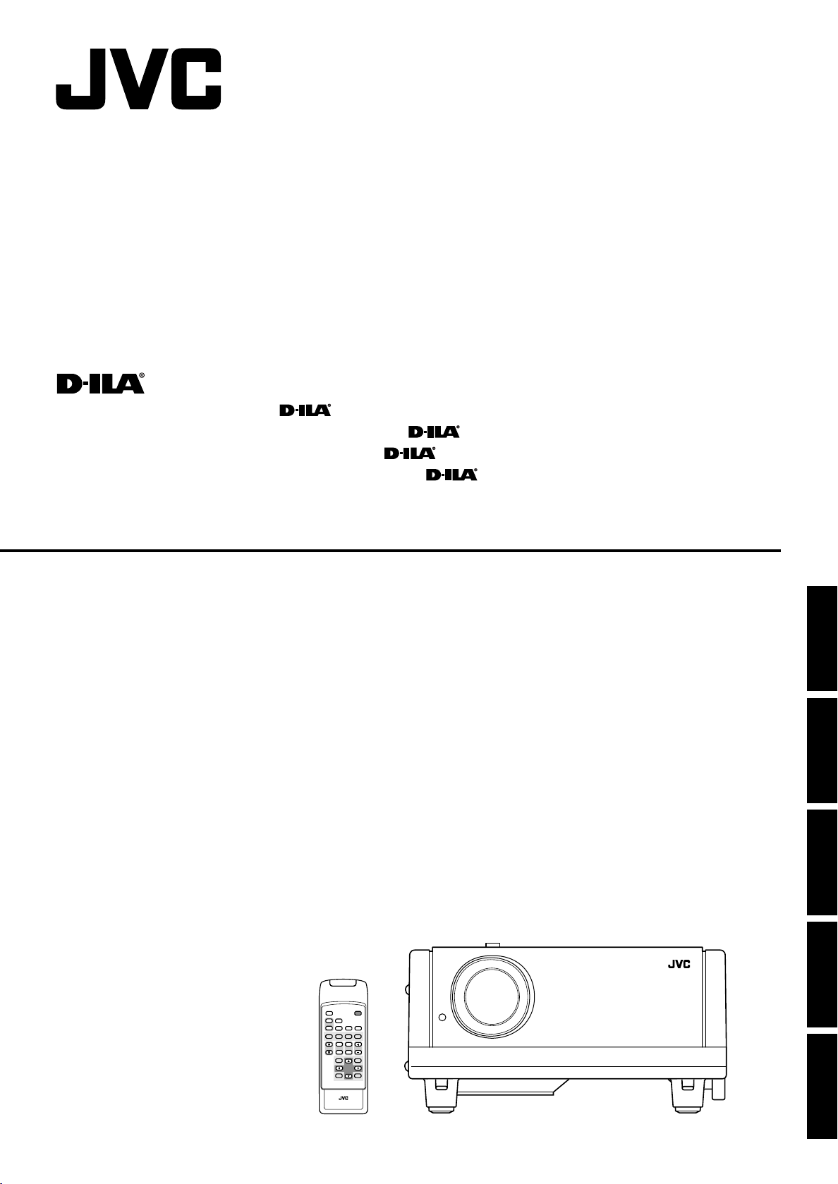
PROJECTOR
BEDIENUNGSANLEITUNG : PROJEKTOR
MANUEL D’INSTRUCTIONS : PROJECTEUR
MANUALE D’ISTRUZIONI : PROIETTORE
MANUAL DE INSTRUCCIONES : PROYECTOR
DLA-G150CLE
INSTRUCTIONS
ENGLISHDEUTSHFRANÇAISITALIANOESPAÑOL
QUICK
ALIGN.
W
W
SCREEN
SCREEN
S
S
PC1 PC2
KEYSTONE
RM-M150 REMOTE CONTROL UNIT
OPERATE
HIDE
FREEZE
VIDEO
Y/C
T
T
DIGITAL
ZOOM FOCUS
ZOOM
W
W
PRESET
MENU
ENTEREXIT
(Lenses are optional)
LCT1124-001A
Page 2

Page 3
Thank you for purchasing this projector. Before using it, read and follow all instructions carefully to take full
advantage of the projector’s capabilities.
SAFETY PRECAUTIONS
IMPORTANT INFORMATION
WARNING :
TO PREVENT FIRE OR SHOCK HAZARDS, DO
NOT EXPOSE THIS APPLIANCE TO RAIN OR
MOISTURE.
WARNING :
THIS APPARATUS MUST BE EARTHED.
CAUTION :
To reduce the risk of electric shock, do not remove cover.
Refer servicing to qualified service personnel.
MACHINE NOISE INFORMATION
(Germany only)
Changes Machine Noise Information Ordinance 3.
GSGV, January 18, 1991: The sound pressure
level at the operator position is equal or less than
70 dB(A) according to ISO 7779.
About burning-in of the D-ILA device
Do not allow the same still picture to be projected for a long
time or an abnormally bright video picture to be projected.
Do not project video images with high-intensity or highcontrast on a screen. The video image could be burned in to
the D-ILA device.
Use special care when projecting video games or computer
program images. There is no problem with ordinary
video-cassette playback images.
About the installation place
Do not install the projector in a place that cannot support its
weight securely.
If the installation place is not sturdy enough, the projector
could fall or overturn, possibly causing personal injury.
IMPORTANT SAFEGUARDS
Electrical energy can perform many useful functions. This
unit has been engineered and manufactured to assure your
personal safety. But IMPROPER USE CAN RESULT IN
POTENTIAL ELECTRICAL SHOCK OR FIRE HAZARD. In
order not to defeat the safeguards incorporated into this
product, observe the following basic rules for its installation,
use and service. Please read these “Important Safeguards”
carefully before use.
– All the safety and operating instructions should be read
before the product is operated.
– The safety and operating instructions should be retained
for future reference.
– All warnings on the product and in the operating
instructions should be adhered to.
– All operating instructions should be followed.
– Place the projector near a wall outlet where the plug can
be easily unplugged.
– Unplug this product from the wall outlet before cleaning.
Do not use liquid cleaners or aerosol cleaners. Use a
damp cloth for cleaning.
– Do not use attachments not recommended by the
product manufacturer as they may be hazardous.
– Do not use this product near water. Do not use
immediately after moving from a low temperature to high
temperature, as this causes condensation, which may
result in fire, electric shock, or other hazards.
– Do not place this product on an unstable
cart, stand, or table. The product may
fall, causing serious injury to a child or
adult, and serious damage to the
product. The product should be mounted
according to the manufacturer’s
instructions, and should use a mount recommended by
the manufacturer.
– When the product is used on a cart, care should be taken
to avoid quick stops, excessive force, and uneven
surfaces which may cause the product and cart to
overturn, damaging equipment or causing possible injury
to the operator.
– Slots and openings in the cabinet are provided for
ventilation. These ensure reliable operation of the
product and protect it from overheating. These openings
must not be blocked or covered. (The openings should
never be blocked by placing the product on bed, sofa,
rug, or similar surface. It should not be placed in a built-in
installation such as a bookcase or rack unless proper
ventilation is provided and the manufacturer’s
instructions have been adhered to.)
For proper ventilation, separate the product from other
equipment, which may prevent ventilation and keep /
distance more than 60 cm.
ENGLISHFRANÇAIS
1
Page 4
– This product should be operated only with the type of
power source indicated on the label. If you are not sure
of the type of power supply to your home, consult your
product dealer or local power company.
– This product is equipped with a three-wire plug. This
plug will fit only into a grounded power outlet. If you are
unable to insert the plug into the outlet, contact your
electrician to install the proper outlet. Do not defeat the
safety purpose of the grounded plug.
– Power-supply cords should be routed so that they are not
likely to be walked on or pinched by items placed upon or
against them. Pay particular attention to cords at doors,
plugs, receptacles, and the point where they exit from the
product.
– For added protection of this product during a lightning
storm, or when it is left unattended and unused for long
periods of time, unplug it from the wall outlet and
disconnect the cable system. This will prevent damage
to the product due to lightning and power line surges.
– Do not overload wall outlets, extension cords, or
convenience receptacles on other equipment as this can
result in a risk of fire or electric shock.
– Never push objects of any kind into this product through
openings as they may touch dangerous voltage points or
short out parts that could result in a fire or electric shock.
Never spill liquid of any kind on the product.
– Do not attempt to service this product yourself as
opening or removing covers may expose you to
dangerous voltages and other hazards. Refer all service
to qualified service personnel.
– Unplug this product from the wall outlet and refer service
to qualified service personnel under the following
conditions:
a) When the power supply cord or plug is damaged.
b) If liquid has been spilled, or objects have fallen on the
product.
c) If the product has been exposed to rain or water.
d) If the product does not operate normally by following
the operating instructions. Adjust only those controls
that are covered by the Operation Manual, as an
improper adjustment of controls may result in damage
and will often require extensive work by a qualified
technician to restore the product to normal operation.
e) If the product has been dropped or damaged in any
way.
f ) When the product exhibits a distinct change in
performance – this indicates a need for service.
– When replacement parts are required, be sure the
service technician has used replacement parts specified
by the manufacturer or with same characteristics as the
original part. Unauthorized substitutions may result in
fire, electric shock, or other hazards.
– Upon completion of any service or repairs to this product,
ask the service technician to perform safety checks to
determine that the product is in proper operating
condition.
– The product should be placed more than one foot away
from heat sources such as radiators, heat registers,
stoves, and other products (including amplifiers) that
produce heat.
– When connecting other products such as VCR’s, and
personal computers, you should turn off the power of this
product for protection against electric shock.
– Do not place combustibles behind the cooling fan. For
example, cloth, paper, matches, aerosol cans or gas
lighters that present special hazards when over heated.
– Do not look into the projection lens while the illumination
lamp is turned on. Exposure of your eyes to the strong
light can result in impaired eyesight.
– Do not look into the inside of this unit through vents
(ventilation holes), etc. Do not look at the illumination
lamp directly by opening the cabinet while the
illumination lamp is turned on. The illumination lamp also
contains ultraviolet rays and the light is so powerful that
your eyesight can be impaired.
– Do not drop, hit, or damage the light-source lamp (lamp
unit) in any way. It may cause the light-source lamp to
break and lead to injuries. Do not use a damaged lightsource lamp. If the light-source lamp is broken, ask your
dealer to repair it. Fragments from a broken light-source
lamp may cause injures.
– Xenon gas is enclosed with high pressure inside the light-
source lamp (lamp unit) of this projector. If you drop or
impart a shock to the lamp, or discard it as is, there is the
possibility of explosion, leading to personal injury. Use
special care when handling the lamp. For any unclear
points, consult your product dealer.
– Do not “ceiling-mount” the projector to a place which
tends to vibrate; otherwise, the attaching fixture of the
projector could be broken by the vibration, possibly
causing it to fall or overturn, which could lead to personal
injury.
– Use only the accessory cord designed for this product to
prevent shock.
The power supply voltage rating of this product is
AC 200 V - AC 240 V, the power cord attached conforms
to the following power supply voltage. Use only the
power cord designated by our dealer to ensure Safety
and EMC.
When it is used by other power supply voltage, power
cable must be changed.
Ensure that the power cable used for the projector is the
correct type for the AC outlet in your country.
Consult your product dealer.
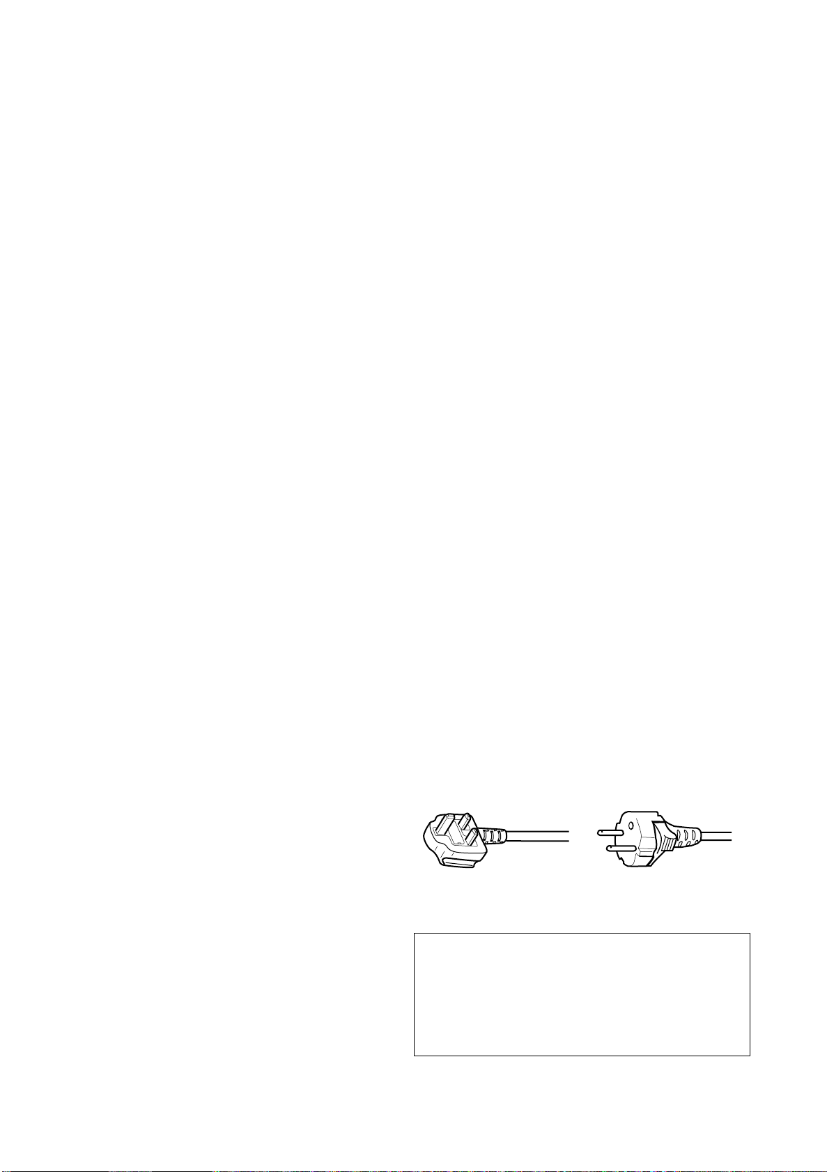
Power cord
For United Kingdom
For European
continent countries
* DO NOT allow any unqualified person to
install the unit.
Be sure to ask your dealer to install the unit (eg.
attaching it to the ceilling) since special technical
knowledge and skills are required for installation.
If installation is performed by an unqualified person, it
may cause personal injury or electrical shock.
2
Page 5
POWER CONNECTION
(United Kingdom only)
WARNING
Do not cut off the main plug from this equipment.
If the plug fitted is not suitable for the power points in your
home or the cable is too short to reach a power point, then
obtain an appropriate safety approved extension lead or
adapter or consult your dealer.
If nonetheless the mains plug is cut off, remove the fuse and
dispose of the plug immediately, to avoid a possible shock
hazard by inadvertent connection to the main supply.
If a new main plug has to be fitted, then follow the instruction
given below:
WARNING:
THIS APPARATUS MUST BE EARTHED.
IMPORTANT:
The wires in the mains lead on this product are coloured in
accordance with the following cord:
Green-and-yellow: Earth
Blue: Neutral
Brown: Live
As these colours may not correspond with the coloured
making identifying the terminals in your plug, proceed as
follows:
The wire which is coloured green-and-yellow must be
connected to the terminal which is marked with the letter
E or the safety earth or coloured green or green-and-yellow.
The wire which is coloured blue must be connected to the
terminal which is marked with the letter N or coloured black.
The wire which is coloured brown must be connected to the
terminal which is marked with the letter L or coloured red.
When replacing the fuse, be sure to use only a correctly
rated approved type, re-fit the fuse cover.
IF IN DOUBT —— CONSULT A COMPETENT
ELECTRICIAN.
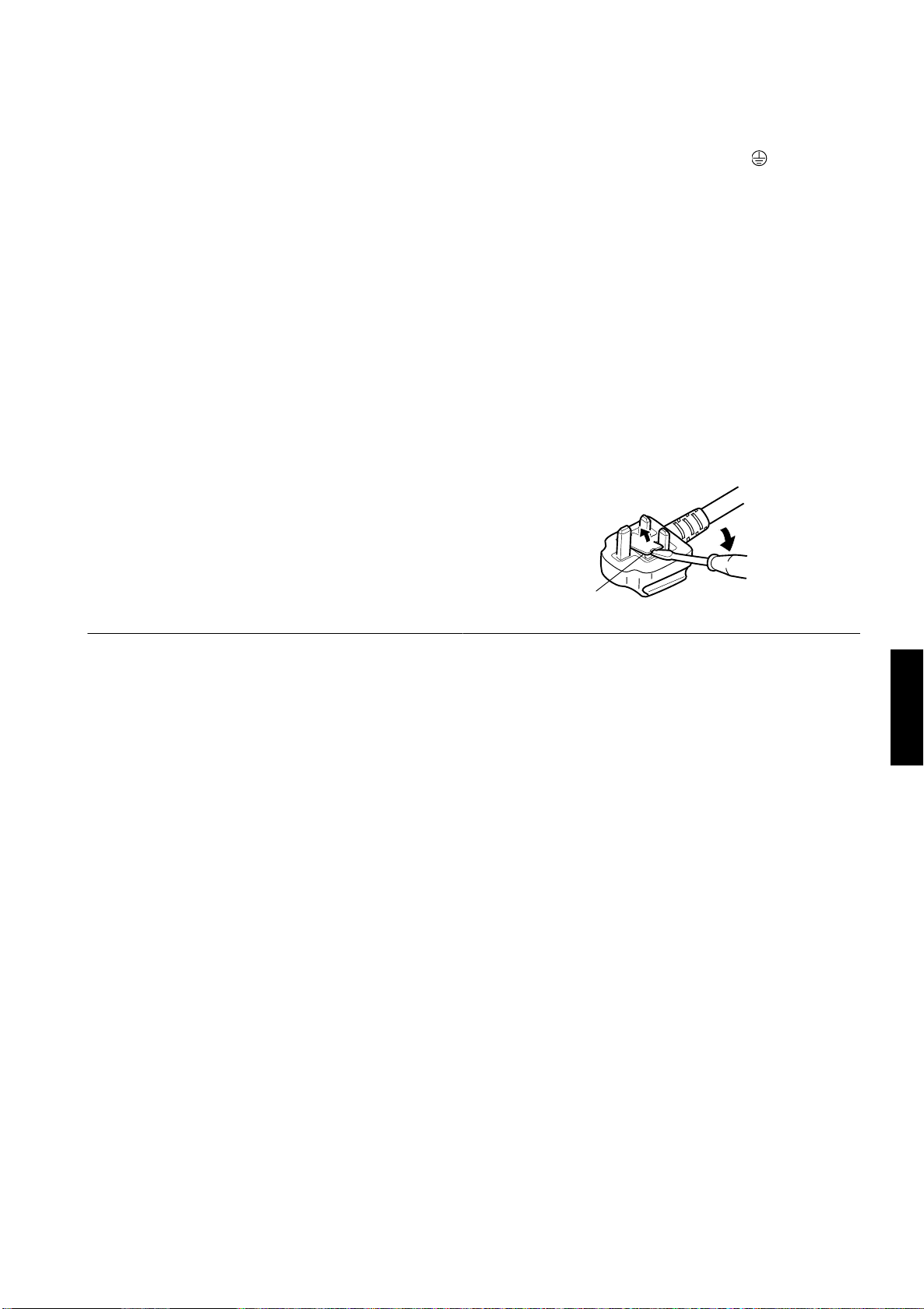
How To Replace The Fuse
Open the fuse compartment with the blade screwdriver, and
replace the fuse.
(* An example is shown in the illustration below.)
Fuse
ENGLISHFRANÇAIS
3
Page 6

Contents
SAFETY PRECAUTIONS ................. 1
Contents........................................... 4
Accessories ..................................... 5
Controls and Features .................... 6
Front Side / Top Surface / Right Side .....................6
Left-hand Side / Rear Side......................................7
Bottom Surface .......................................................8
Control Panel on the Projector ................................9
Connector Panel ...................................................11
Remote Control Unit..............................................12
Installing Batteries.................................................14
Precautions for using batteries..............................14
Installing the Projector.................. 15
Precautions for Installation....................................15
Adjusting the Inclination of the Projector...............16
Installing the Projector against the Screen............17
Projection Distance and Screen Size....................18
Setting the Amount of Lens Shifting......................19
Effective Range and Distance of the
Remote Control Unit..............................................20
Setting the Position Selecting Screw for Ceiling
Mounting ...............................................................21
When installing (adjusting/setting) the unit............21
Connecting to Various Devices.... 22
Signals that Can Be Input to the Projector ............22
Connecting to Video Devices ................................24
Connecting to Hi-Vision Devices/DVD Players .....25
Connecting to Other Devices ................................26
Connecting to Devices which Control the
Projector................................................................27
Connecting to Computer Devices .........................28
Connecting to DVI .................................................29
How to attach the ferrite core................................29
Connecting the Power Cord ..................................30
Removing the Lens Cap........................................30
Basic Operations........................... 31
1. Turning on the Power........................................32
2. Select the Input source to be Projected ............33
3. Adjust the Screen Size (Zooming) ....................34
4. Adjust Focus .....................................................34
5. Setting the Screen Aspect Ratio .......................34
Turning off Image (HIDE) ......................................35
Removing the Trapezoidal Distortion of the
Image ....................................................................35
Quick Alignment Function (QUICK ALIGN.)..........36
Displaying a Still Picture (FREEZE) ......................37
Zooming a Part of the Image
(DIGITAL ZOOM T/W) ..........................................37
Menu Operations ........................... 38
Basic Menu Operation...........................................43
Changing the Color System
(Video Menu Mode Only) ......................................45
Changing the Language Display ...........................46
Changing the Screen aspect ratio/HDTV format
(Video Menu Mode Only) ......................................46
Adjusting Tracking/Phase .....................................47
Setting for Watching Image Software
(Video Menu Mode Only) ..................................... 48
Adjusting Picture Quality ...................................... 49
Adjusting Color temperature................................. 50
Adjusting the Video Screen/Menu Position .......... 51
Changing the Image Gamma/Aspect Ratio
(Video Menu Mode Only) ..................................... 52
Changing the Image Size - Resize Function
(PC Menu Mode Only).......................................... 53
Changing the Clamp pulse position
(PC Menu Mode Only).......................................... 53
Setting and Adjusting Other Functions
(OPTIONS)........................................................... 54
Getting Information............................................... 56
Replacing the Fuse........................ 57
Replacing the Light-Source
Lamp ...............................................58
Cleaning and Replacing the
Filter Cover..................................... 63
Troubleshooting............................. 64
Warning Indication......................... 66
Warning Messages ........................67
Specifications................................. 70
Outside dimensions.............................................. 72
Pin assignment (Specifications for terminals) ...... 73
RS-232C external control ..............74
Appendix......................................... 76
4
Page 7
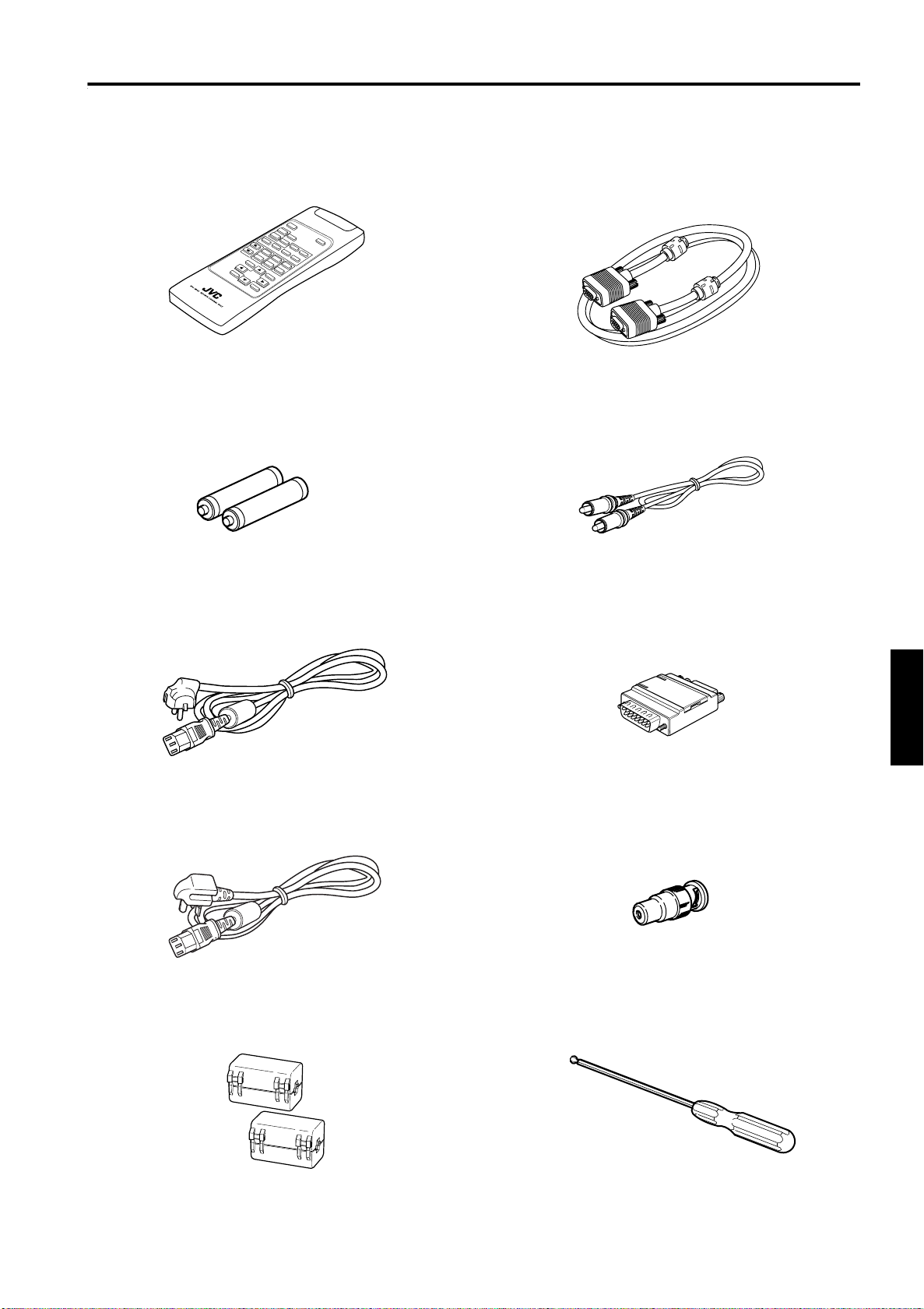
Accessories
The following accessories are included with this projector. Check for them; if any item is missing, please
contact your dealer.
■■■■ Remote control unit (RM-M160G)
■■■■ AA/R6-size dry cell battery (××××2)
(for checking operation)
■■■■ Power cord
[approx. 2.5 m]
(for European continental countries)
■■■■ Personal computer connection cable
[approx. 2 m]
(D-sub, 3-row 15 pin)
■■■■ Video cable
[approx. 2 m]
■■■■ Conversion adapter for Mac
(for Macintosh)
(for United Kingdom)
■■■■ Ferrite core (××××2)
ENGLISHDEUTSHFRANÇAISITALIANOESPAÑOL
■■■■ BNC-RCA Conversion plug
■■■■ Hex. wrench
5
Page 8

Controls and Features
Front Side / Top Surface / Right Side
R
TE
N
E
U
N
E
M
EO
D
I
V
PC
IT
X
E
E
AT
R
E
P
O
ET
S
E
E
R
N
P
O
T
E
S
Y
P
E
HID
K
EM
T
P
M
A
L
P
U
9
8
7
6
N
W
O
D
5
4
3
1
2
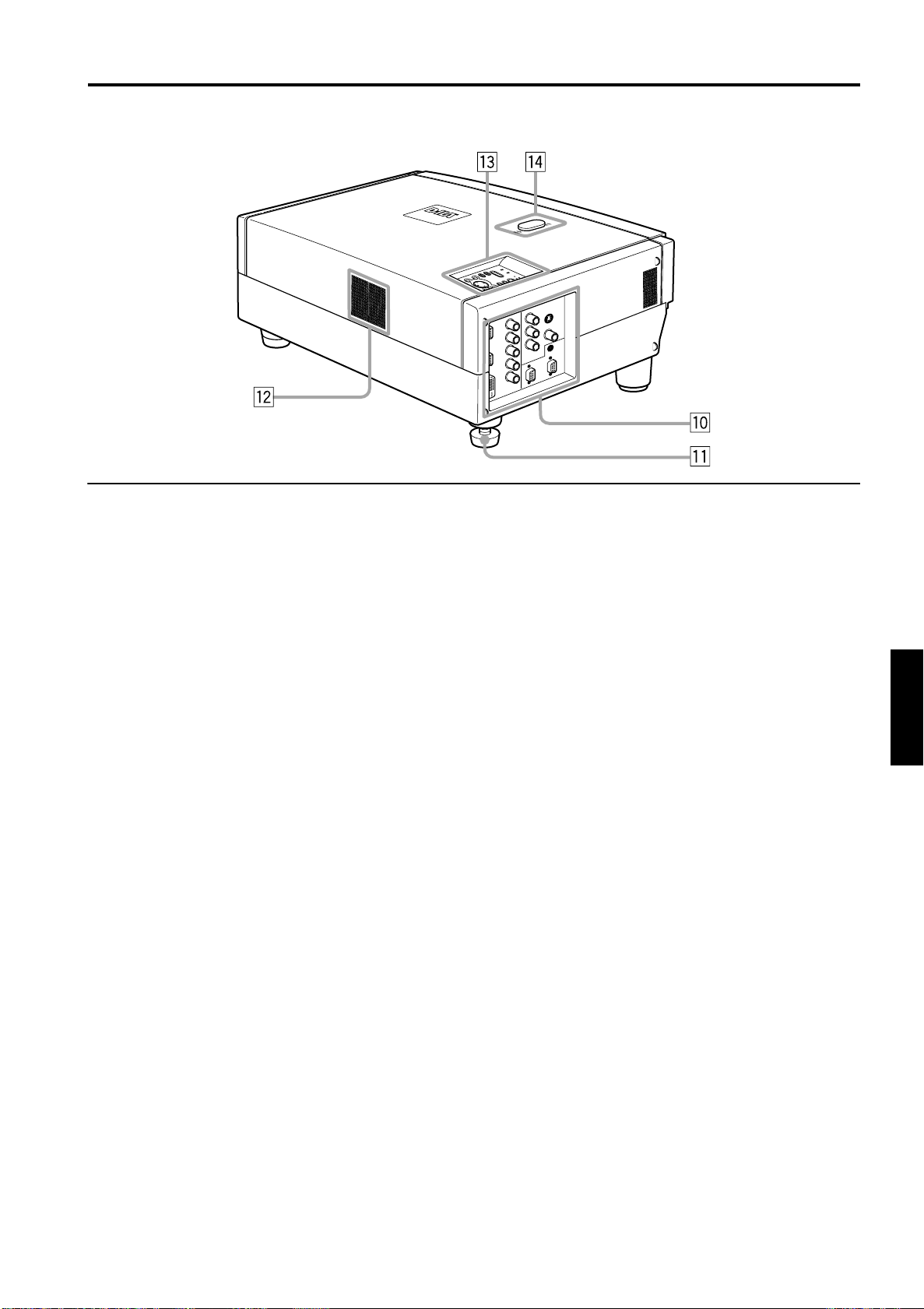
Exhaust vents
1
Vents for cooling fans through which warm air comes out.
CAUTION
• Do not block the exhaust vents, or heat will build up inside,
possibly causing a fire. Also, do not touch the vents, or this
could give you a low-temperature burn.
Carrying handle
2
Raise this handle when carrying the projector.
CAUTIONS
• When carrying the projector, do not transmit shocks to it.
Also be careful to keep it balanced.
• Do not carry it while the light-source lamp is on or the
cooling fan is operating. This could cause personal injury.
AC IN (power input) terminal
3
This is the power input terminal where the supplied
power cord is connected. For details, refer to page 30.
Fuse holder
4
A fuse rated T6.3A H 250 V is installed. (Power source
protection)
To replace the fuse, refer to page 57.
CAUTION
• When replacing the fuse, use the same rating and type.
Otherwise, a fire may occur and/or the projector may be
damaged.
MAIN POWER switch
5
This is the main power switch. When it is turned on, the
projector goes into stand-by state, and the STAND BY
indicator on the control panel comes on. (Refer to
page 32.)
ON [ | ]: The main power turns on.
OFF [‡‡‡‡]: The main power turns off.
Adjustable feet (for adjusting the height and
6
angle)
By extending the feet, the projector angle can be
adjusted up to +7°.
For details, refer to “Adjusting the Inclination of the
Projector” on page 16.
Lens
7
One of the optional lens units should be installed before
using the projector.
A lens-hole blind cover (black one) is installed when the
projector is shipped from the factory.
For details on the types of optional lenses available, refer
to page 18.
CAUTION
• Please consult your authorized dealer or service center for
information about attaching an optional lens.
Lens cap
8
This is the lens cap provided for the optional lens.
When you are not using the projector, attach the lens cap
to protect the lens from dirt or being damaged. (Refer to
page 30.)
Remote sensor
9
When operating with the remote control, aim it toward
this sensor. (Refer to page 20.)
6
Page 9
Left-hand Side / Rear Side
L
A
M
P
T
E
M
P
S
T
A
N
D
B
Y
M
E
N
U
K
E
Y
S
T
O
N
E
P
R
E
S
E
T
E
X
I
T
E
N
T
E
R
O
P
E
R
A
T
E
p Connector panel
For details, refer to “Connector Panel” on page 11.
Rear adjustable foot (for leveling the projector)
q
It is set at the shortest position when shipped from the
factory. Turn the foot to make the projector level.
Adjustment can be made in the range of +1.5° and –1.5°
from the horizontal position. For details, refer to
“Adjusting the Inclination of the Projector” on page 16.
w Air inlet
This is the air inlet. Do not cover or obstruct this slot.
Control panel
e
For details, refer to “Control Panel on the Projector” on
page 9.
r Lens shift knob cap
When you have mounted a lens that uses the lens shift
function, open this cap and rotate the lens shift knob to
move the lens position. For more information, refer to
“Setting the Amount of Lens Shifting” on page 19.
Controls and Features
U
P
D
O
W
N
H
I
D
E
P
C
V
I
D
E
O
ENGLISHDEUTSHFRANÇAISITALIANOESPAÑOL
7
Page 10
Controls and Features
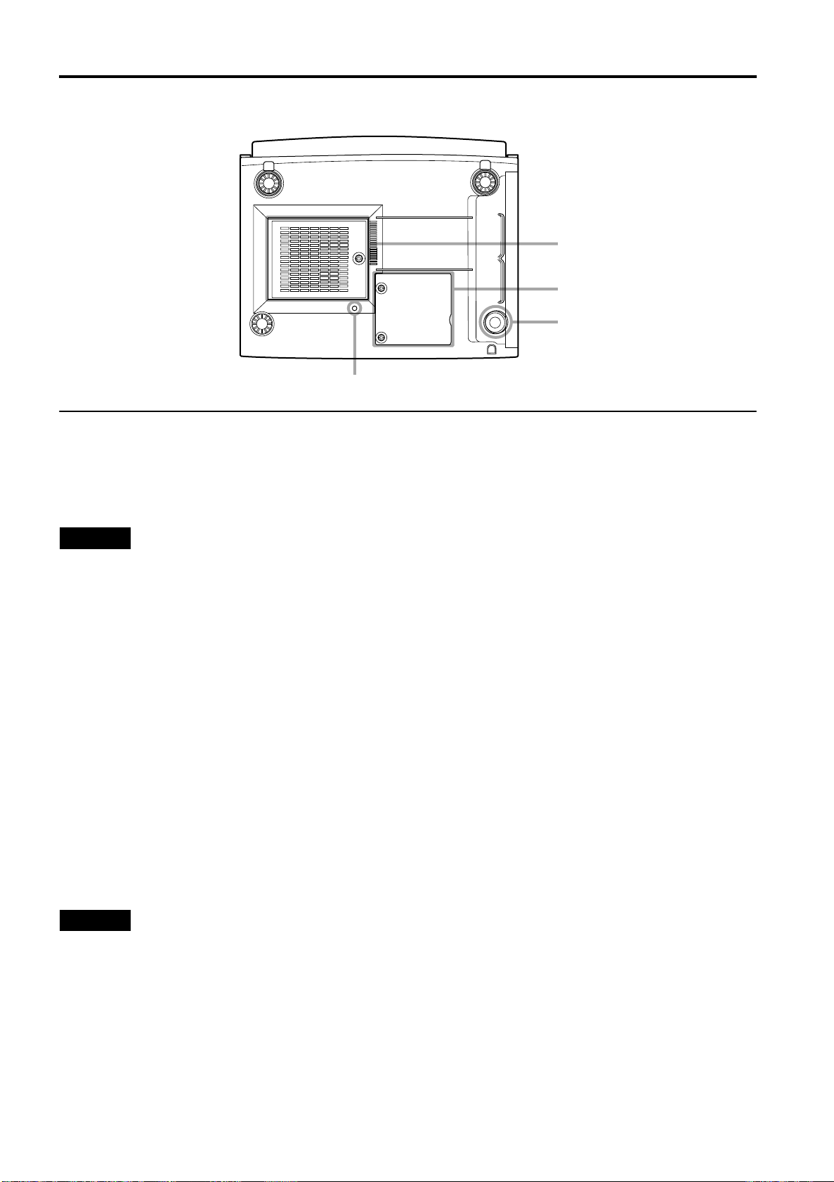
Bottom Surface
i
t Air inlet (filter)
Air is taken in through the filter to cool the light-source
lamp. If the filter is blocked or if something that obstructs
the flow of air is placed around the projector, heat may
build up inside and could cause a fire. For required
space, refer to “Precautions for Installation” on page 15.
t
y
u
CAUTIONS
• Be careful as paper, cloth or soft cushion could be drawn in
if placed nearby. Do not block the filter, or heat may build
up and could cause a fire.
• Clean the filter periodically. For details, refer to “Cleaning
and Replacing the Filter Cover” on page 63. Deposition of
dirt on the filter reduces the cooling effect, causing heat to
build up inside, which could cause a fire or malfunction.
Opening for replacing the light-source lamp
y
For replacing the light-source lamp, refer to “Replacing
the Light-Source Lamp” on page 58.
u Fixing foot
i Position selecting screw for ceiling mounting
When using the projector in an upside-down, ceilingmounted position (inverted top-to-bottom and right-toleft), the “position selecting screw for ceiling mounting”
must be turned to switch to ceiling mounting.
This will correct variance in color images (shading),
which otherwise would occur in ceiling mounting.
For more information, refer to “Setting the Position
Selecting Screw for Ceiling Mounting” on page 21.
CAUTION
• To ceiling-mount and adjust the projector, special expertise
and technique are necessary. Be sure to ask your dealer or
specialist to perform this work.
8
Page 11
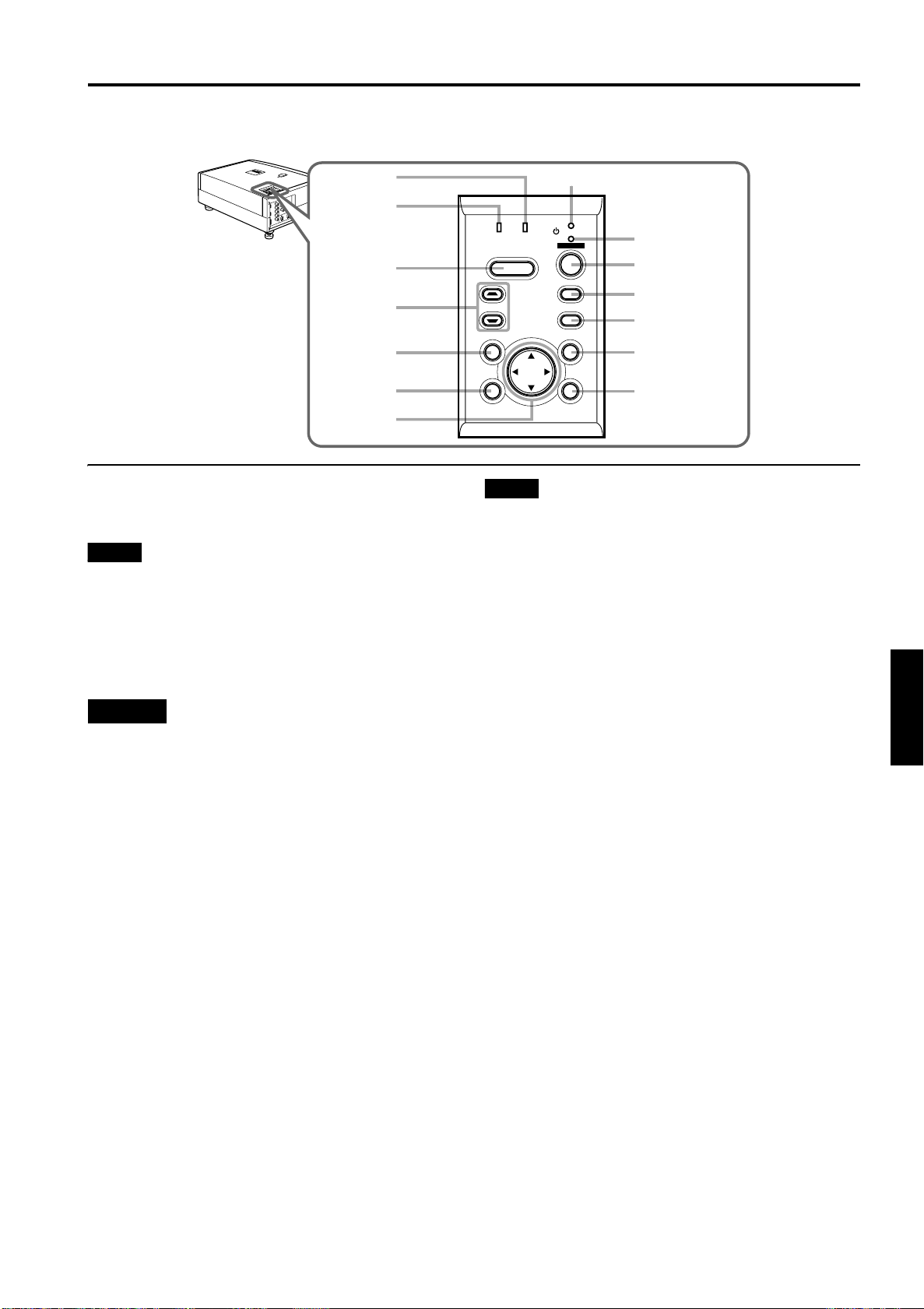
Control Panel on the Projector
LA
M
P
T
E
M
P
ST
A
N
D
B
Y
M
E
NU
KE
YS
T
O
NE
PR
E
S
ET
EX
IT
E
NT
E
R
O
P
ER
A
T
E
U
P
D
O
W
N
H
ID
E
P
C
V
ID
E
O
r
e
w
q
p
LAMP TEMP
KEYSTONE
PRESET
HIDE
1
STAND BY
OPERATE
PC
VIDEO
MENU
Controls and Features
2
3
4
5
6
9
8
STAND BY Indicator
1
ON : When in stand-by mode.
Blinking :When in cool-down mode.
Memo
About the cool-down mode:
This projector has a function to cool down the heated lamp for a
fixed period of time (approx. 120 seconds) after projection is
finished. This feature is referred to as the cool-down mode.
The purpose of the cool-down mode is to prevent inner parts
from being deformed or broken by heat from the heated lamp
as well as to prolong the life of the lamp.
CAUTIONS
• Do not turn off the MAIN POWER switch while in the cooldown mode.
• Do not place the projector on its side or stand it upright
while in the cool-down mode; this may block the vents.
2 OPERATE indicator
ON : When the projector is in operation (projecting).
OFF : When the projector is not in operation (not
projecting).
OPERATE button
3
When the projector is in the stand-by mode, press this
button one second or more, and the projector is turned
on, causing the OPERATE indicator to light.
Press it one second or more again, and the projector
goes into the cool-down mode, then stand-by mode.
(Refer to page 32.)
* You cannot use the OPERATE button for about one
minute after the lamp blinks. Press the button after a
minute or longer has elapsed.
EXIT ENTER
7
Memo
While in the cool-down mode (STAND BY indicator is blinking):
Even if you press the OPERATE button, the projector is not
turned on. Wait until the projector enters stand-by mode
(STAND BY indicator stays lit).
4 PC button
Use this button to select a device connected to the PC 1,
PC 2 or DVI terminals. Each time you press the button,
the selection alternates among PC 1, PC 2 and DVI.
* “PC1” , “PC2” or “DVI” will be displayed on the top right of
the projected image. (This function can be disabled by
the menu.)
5 VIDEO button
Use this button to select a device such as a video deck
connected to the AV IN (Y/C, VIDEO or COMP) terminal
of the projector. Each time you press the button, the
selection alternates among Y/C, VIDEO and COMP.
* “Y/C”, “VIDEO” or “COMP” will be displayed on the top right of
the projected image. (This function can be disabled by the
menu.)
MENU button
6
Use this button to enter or exit the menu mode. The main
menu appears or disappears at the screen. For details,
refer to “Basic Menu Operation” on page 43.
ENTER button
7
This button will be used in the menu mode. Use to
display the hierarchical menus. Also use when “ENTER”
is displayed against the item on the menu screen or
when the “All reset” selection is confirmed. For details,
refer to “Basic Menu Operation” on page 43.
Cursor buttons 5/∞/2/
8
These buttons will be used in the menu mode to select an
item, or to set or adjust the value. For details, refer to
“Basic Menu Operation” on page 43.
3
ENGLISHDEUTSHFRANÇAISITALIANOESPAÑOL
9
Page 12

Controls and Features
9 EXIT button
This button will be used in the menu mode to return to the
previous menu. When the main menu is displayed, this
button will cause the menu to disappear. For details, refer
to “Basic Menu Operation” on page 43.
p PRESET button
This PRESET button only works as a reset button for the
direct button adjustment of the KEYSTONE button of the
control panel and the DIGITAL ZOOM button of the
remote control. When adjusting the keystone or digital
zoom (when the setting is displayed on the screen) the
adjusted value is reset to that which was set when the
projector was shipped from the factory. Of the menu
items, this button only works for the keystone setting
screen.
q KEYSTONE / buttons
Use these buttons to correct a trapezoidal distortion of
the projected image. (Refer to page 35.)
HIDE button
w
Use this button to turn off the image on the screen
temporarily. Pressing it again restores the image to
resume. (Refer to page 35.)
LAMP indicator
e
ON : After the light-source lamp has been used for
more than approx. 900 hours. (NORMAL only)
Blinking
: After the light-source lamp has been used for
more than approx. 1000 hours (1900 hours in the
LPC or LOC mode). Replace the light-source
lamp. Refer to “Replacing the Light-Source
Lamp” on page 58 or page 59.
r TEMP indicator
Blinking : The temperature inside the projector has risen
abnormally.
Note
• While the TEMP indicator is blinking (during abnormal
temperature), the power is automatically cut off.
10
Page 13
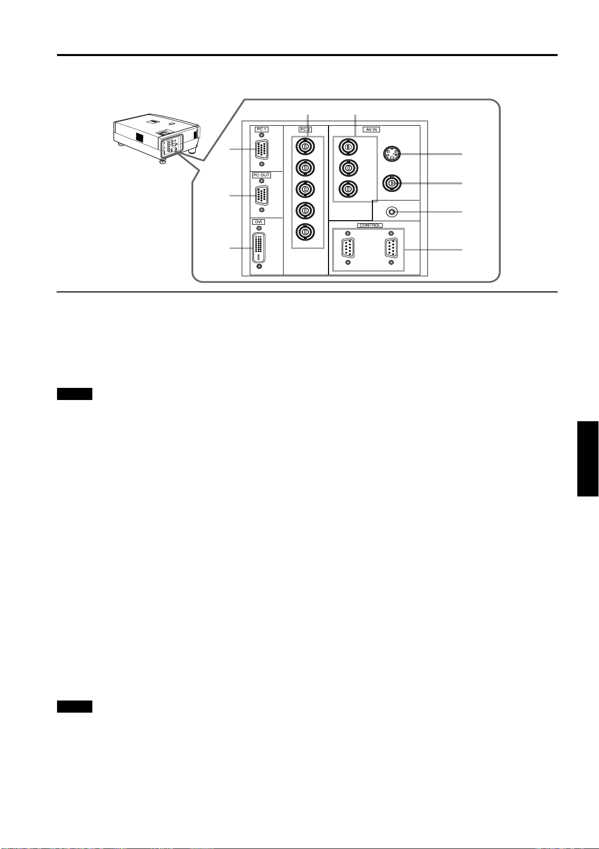
Connector Panel
L
A
M
P
T
E
M
P
S
T
A
N
D
B
Y
M
E
N
U
K
E
Y
S
T
O
N
E
P
R
E
S
E
T
E
X
I
T
E
N
T
E
R
O
P
E
R
A
T
E
Controls and Features
U
P
D
O
W
N
H
I
D
E
P
C
V
I
D
E
O
1
2
3
1 PC (computer) 1 input terminal (D-sub 3-row 15
pin)
This is an input terminal dedicated to computer signals
(RGB video signals and sync signals).
Connect the display output terminal of the computer to
this terminal. When a Macintosh computer is to be
connected, use the supplied conversion adapter for Mac.
Note
• When computer-related signals are input, the uppermost
edge of the image may appear to bow if the sync signal
input is composite sync (Cs) or G on sync signal. In this
case, use separate sync signals for vertical sync (V) and
horizontal sync (H).
2 PC (computer) OUT terminal (D-sub 3-row 15 pin)
This is the terminal for video output from the monitor of
the computer connected to PC1 or PC2.
The computer input signal projected on the screen is
output. A display monitor can be used by connecting it to
this terminal.
3 DVI terminal [DVI-D 24 pin]
This is the digital RGBHV input terminal.
• The Mac ADC is not supported.
4 PC (computer) 2 input terminals (BNC ×
These are multipurpose video input terminals that allow
input of the following signals.
• Analog RGB signals, vertical sync (V) signals, and
horizontal sync (H) signals / composite signals (Cs).
(Devices which have analog RGB signal output
terminals can be connected.)
* Input of external sync signals is automatically detected.
Detection of H/V signals or Cs signals causes automatic
switching to external sync. The priority order is H/V > Cs.
IN
5)
×××
54
R
G
B
H
V
Y
B
/B-Y
P
R
/R-Y
P
REMOTE
Y/C
VIDEO
6
7
8
9
IN OUT
5 Component terminal
Component signals (Y, B-Y, R-Y) or DTV-format (Y, PB,
) signals. (Devices which have component output
R
P
terminals can be connected.)
* For details about DTV-format signals (480i, 480p, 720p,
1080i) compatible with this unit, refer to page 22.
6 Y/C (S-video) input terminal (Mini DIN 4 pin)
Connect this terminal to the S-video output terminal of a
video deck, etc.
Attach the ferrite core (accessory) to the cable which is
connected to the Y/C input terminal. (Refer to page 29.)
7
VIDEO (composite video) input terminal (BNC)
Connect this terminal to the composite video output
terminal of a video deck, etc.
REMOTE terminal (stereo mini jack)
8
Connect an infrared remote control extension unit, etc. to
this jack.
Attach the ferrite core (accessory) to the cable which is
connected to the REMOTE terminal. (Refer to page 29.)
* For details, consult your dealer.
RS-232C CONTROL terminal IN/OUT (D-sub 9 pin)
9
This is the RS-232C interface-specified terminal. The
projector can be controlled by a computer connected
externally.
* For details, refer to page 27 and 74.
ENGLISHDEUTSHFRANÇAISITALIANOESPAÑOL
Note
• When computer-related signals are input, the uppermost
edge of the image may appear to bow if the sync signal
input is composite sync (Cs) or G on sync signal. In this
case, use separate sync signals for vertical sync (V) and
horizontal sync (H).
11
Page 14
Controls and Features
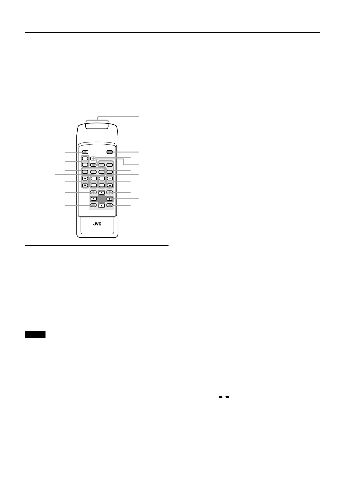
Remote Control Unit
On the remote control, the same buttons as on the control
panel of the projector are provided except for the following
buttons. For the same buttons, operation is the same in
principle.
For remote control only:
DIGITAL ZOOM T/W, QUICK ALIGN., FREEZE, ZOOM T/
W, FOCUS +/–, SCREEN W/S, PC 1, PC 2, VIDEO, Y/C,
DVI, COMP.
1
r
u
y
t
e
w
QUICK
ALIGN.
W
W
SCREEN
SCREEN
S
S
PC1 PC2
KEYSTONE
HIDE
FREEZE
DIGITAL
ZOOM
PRESET
T
W
OPERATE
COMP
VIDEO
DVI
T
ZOOM FOCUS
W
MENU
2
3
Y/C
5
4
6
7
8
9
q
RM-M160 REMOTE CONTROL UNIT
ENTEREXIT
1 Remote control’s signal transmitter
2 OPERATE button
When the projector is in the stand-by mode, press this
button one second or more, and the projector is turned
on, causing the OPERATE indicator to light.
Press it one second or more again, and the projector
goes into the cool-down mode, then stand-by mode.
(Refer to page 32.)
* The OPERATE button will not work for approximately 1
minute from when the light-source lamp is turned on. Use
the button after approximately 1 minute.
Memo
While in the cool-down mode (STAND BY indicator is
blinking):
Even if you press the OPERATE button, the projector is not
turned on. Wait until the projector enters stand-by mode
(STAND BY indicator stays lit).
HIDE button
3
Use this button to turn off the image on the screen
temporarily. Pressing it again makes the image to
resume. (Refer to page 35.)
FREEZE button
4
During projection of an image on the screen, press this
button to obtain a still picture.
To restore normal projection, press it again. (Refer to
page 37.)
* Depending on the video signal source (UXGA, etc.), this
button does not work.
p
5 VIDEO button
Use this button to select a device such as a video deck
connected to the AV IN terminal (VIDEO, Y/C or COMP
input terminal) of the projector. Each time you press the
button, the selection alternates among Y/C, VIDEO and
DVI. (Refer to page 33.)
* “Y/C”, “VIDEO” or “DVI” will be displayed on the top right
of the projected image. (This function can be disabled by
the menu.)
6 ZOOM T/W buttons
Use these buttons to adjust the projected screen size.
T (Tele): The projected screen size decreases.
W (Wide):The projected screen size increases.
7 FOCUS +/– buttons
Use these buttons to adjust the focus of the projected
video image.
+ : The focus point becomes more distant.
– : The focus point becomes nearer.
MENU button
8
Use this button to enter or exit the menu mode. The main
menu appears or disappears at the screen. For details,
refer to “Basic Menu Operation” on page 43.
Cursor buttons 5/∞/2/
9
These buttons are used in the menu mode to select an
item or to set or adjust the value. For details, refer to
“Basic Menu Operation” on page 43.
ENTER button
p
This button is used in the menu mode. Use to display the
hierarchical menus. Also use when “ENTER” is displayed
against the item on the menu screen or when the “All
reset” selection is confirmed. For details, refer to “Basic
Menu Operation” on page 43.
EXIT button
q
This button is used in the menu mode to return to the
previous menu. When the main menu is displayed, this
button will cause the menu to disappear. For details, refer
to “Basic Menu Operation” on page 43.
PRESET button
w
This PRESET button only works as a reset button for the
direct button adjustment of the KEYSTONE button of the
control panel and the DIGITAL ZOOM button of the
remote control. When adjusting the keystone or digital
zoom (when the setting is displayed on the screen) the
adjusted value is reset to that which was set when the
projector was shipped from the factory. Of the menu
items, this button only works for the keystone setting
screen.
KEYSTONE / buttons
e
Use these buttons to correct a trapezoidal distortion of
the projected image. (Refer to page 35.)
3
12
Page 15

r DIGITAL ZOOM T/W buttons
A part of image can be magnified up to four times on the
screen.
Each time the T or W button is pressed, the image is
enlarged or the enlarged image is reduced by a certain
degree. (Refer to page 37.)
* Images which are enlarged with the digital zoom become
less clear.
* Depending on the video signal source (UXGA, etc.), this
button does not work.
t PC buttons
Use these buttons to select a device connected to the PC
1, PC 2 or DVI terminals. (Refer to page 33.)
* “PC 1”, “PC 2” or “DVI” will be displayed on the top right
of the projected image. (This function can be disabled
using the menu.)
y SCREEN W/S buttons
Changes the projection screen size to [4:3] or [16:9].
u QUICK ALIGN. (Quick Alignment) button
Use this button to automatically align “Horizontal and
vertical position”, “Tracking” and “Phase” for the
projected image.
During the automatic alignment, “Quick Alignment”
appears on the screen, and disappears after alignment is
finished. (Refer to page 36.)
* The “Quick Alignment” function only works when the
signal is input from the input terminal of PC 1, PC 2 or
DVI. It does not work when the signal is input from the
VIDEO IN terminal (VIDEO, Y/C and COMP. input
terminal).
Controls and Features
CAUTION
• Automatic alignment with the quick alignment function
should be carried out on a bright still-picture. This function
may not work correctly on a dark picture or motion-picture.
If adjustment with this function is not satisfactory, adjust
“Horizontal and vertical position”, “Tracking” and “Phase” in
the menu mode.
ENGLISHDEUTSHFRANÇAISITALIANOESPAÑOL
13
Page 16
Controls and Features
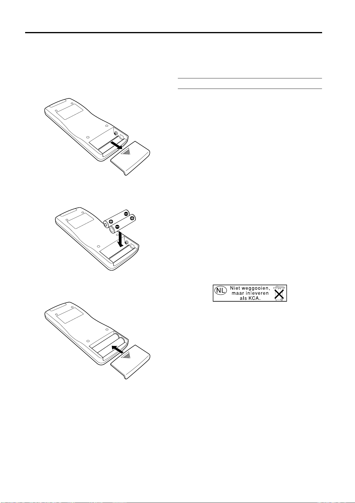
Installing Batteries
Install batteries in the remote control. If the remote control has started to work erratically, replace the
batteries.
Open the back cover.
1
Open the back cover in the direction of the arrow.
Install the batteries.
2
Place the two supplied batteries (AA/R6-size) in the
remote control as illustrated below.
Precautions for using batteries
If batteries are used incorrectly, they may crack or
leak liquid. This could cause a fire, burn, malfunction,
or staining or damaging of the surroundings.
Beware of the following:
• Do not mix new and old batteries.
• Do not mix different types of batteries as they differ in
characteristics.
• Place batteries so they match the polarities indicated:
(+) to (+) and (–) to (–).
• Be sure to put the minus (–) end in first to avoid
short-circulating.
• Use only designated batteries.
• Remove the batteries if the remote is not to be used for a
prolonged period.
• When the batteries are exhausted, replace them
immediately. Otherwise, liquid could leak, or malfunction
could occur due to leaking liquid. If the leaked liquid
contacts the skin, wipe it off with a cloth, otherwise the skin
could become rough.
• Do not put batteries into a fire or try to recharge them.
• Batteries run for six months to one year in normal use.
However, the batteries supplied are for confirming
operation and may not run that long. When the remote
control starts failing to work properly, replace the batteries
with new ones.
Close the back cover.
3
First fit the claws on the back cover in the case, then
close the back cover in the direction of the arrow.
This instruction below applies only to the use in Holland.
Gebruike batterijen:
14
Page 17
Installing the Projector
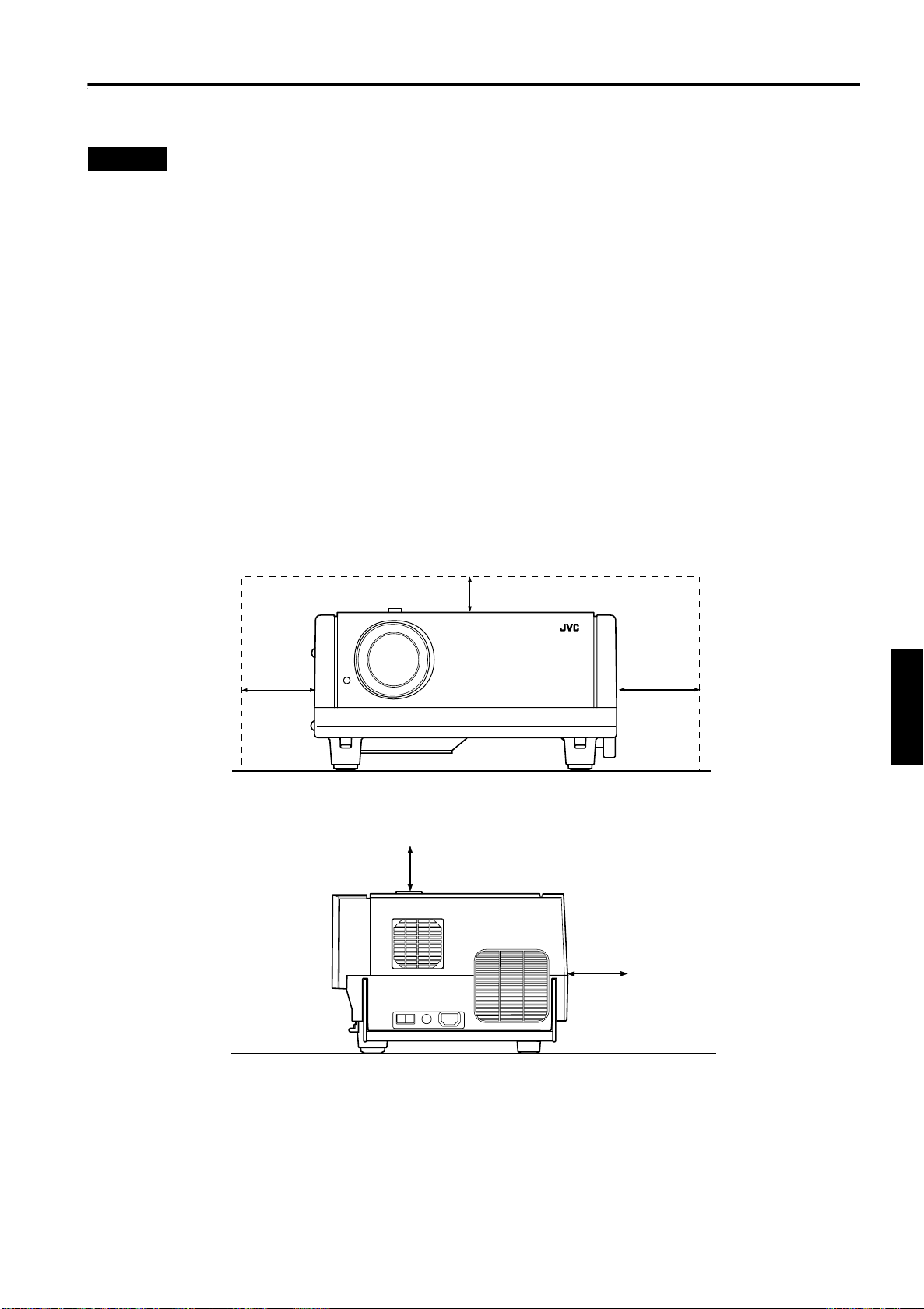
Precautions for Installation
CAUTIONS
1. Before installation, do not connect the projector’s power cord.
2. Do not install the projector in the following places:
• Where there is water, humidity or dust.
• Where the projector may be subjected to oil, smoke or cigarette smoke.
• On a soft surface such as a carpet or cushion.
• Where the projector may be subjected to direct sunlight.
• Where temperature is high or humidity is low.
Allowable operation temperature range: +5°C to +35°C
Allowable relative humidity range: 20% to 80% (no condensation)
Allowable storage temperature range: –10°C to +60°C
■
When installing the projector, observe the following:
• Do not use the projector placed on its side.
Avoid using the projector placed on its side. This could cause a malfunction.
• Use the projector within the specified angle.
Do not use the projector inclined ±30° horizontally (left/right). This could cause color variation or shorten the lamp life.
• Do not block the exhaust vents.
Do not use a cover which encloses the projector air-tight or blocks the exhaust vents. Allow sufficient space around the
projector. When the projector is enclosed in a space of the following dimensions, use an air conditioner so the temperature
inside becomes equal to the outside temperature.
Allowable minimum space required
200mm
300mm
600mm
ENGLISHDEUTSHFRANÇAISITALIANOESPAÑOL
300mm
200mm
15
Page 18
Installing the Projector
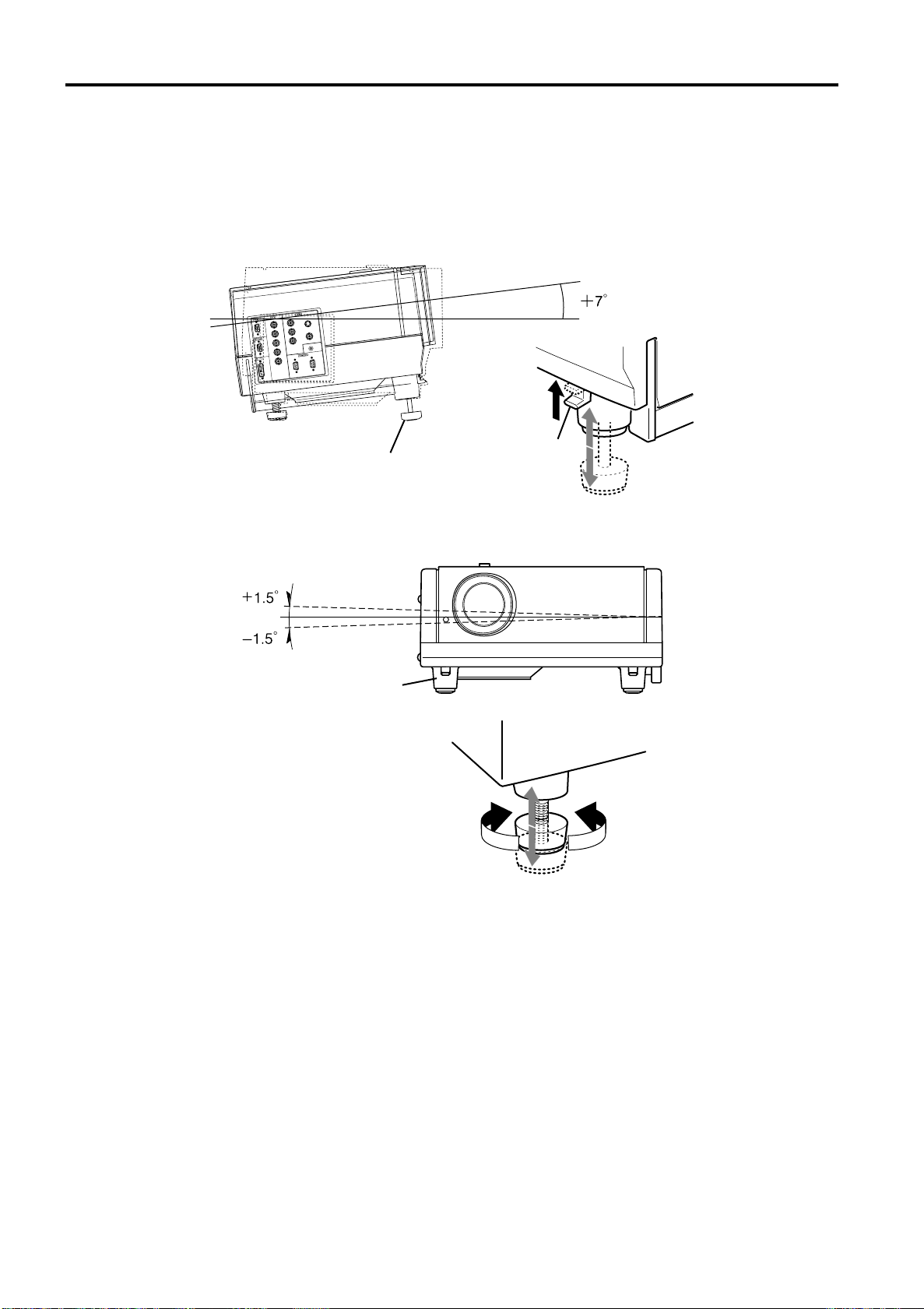
Adjusting the Inclination of the Projector
The vertical angle and the leveling of the projector can be adjusted with the adjustable feet at the bottom of the projector.
Adjusting the vertical angle of the projector
■
While pushing the levers on both sides upward, raise the projector. The adjustable feet automatically extend.
To retract the feet, push the levers and lower the projector slowly; the projector is fixed at the position
where you release the levers.
Y
Y/C
R
-Y
/B
B
P
G
VIDEO
-Y
/R
R
P
B
REMOTE
H
DVI
V
IN
OUT
IN
Adjustable feet (at the front)
lever
Leveling the projector
■
Lift the projector, rotate the rear adjustable foot, and adjust the horizontal angle until the projector is level.
Adjustable foot (at the rear)
Fixing foot (at the rear)
ShortenExtend
16
Page 19
Installing the Projector
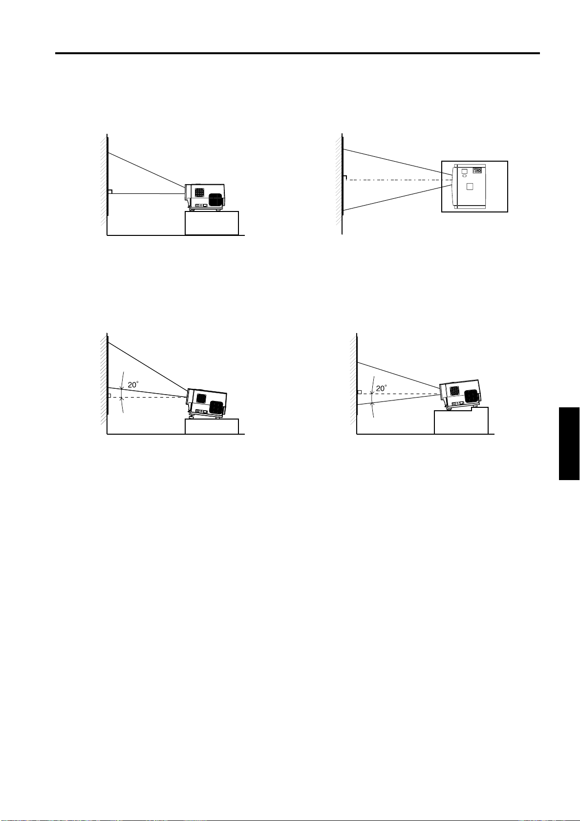
Installing the Projector against the Screen
The projector should be placed so that the center line of the lens is at a right angle to the screen as shown in the following
figures.
Side view
■
Trapezoidal-distortion correctable maximum angle
■
The projector has a function to correct the trapezoidal distortion of the projected image on the screen.
To correct this distortion, use the KEYSTONE buttons on the projector. (Refer to “Removing the Trapezoidal Distortion of the
Image” on page 35.) Also, correction is possible by using the “Keystone” menu. (Refer to “Setting and Adjusting Other
Functions (OPTIONS)” on page 54.)
Correctable angle:
Top view
■
Correctable angle:
PC
MENU
VIDEO
STAND BY
OPERATE
HIDE
LAMPTEMP
PRESET
ESCAPE ENTER
KEYSTONEVOLUME
Up to approx. 20° upward from the horizontal line
Up to approx. 20° downward from the horizontal line
ENGLISHDEUTSHFRANÇAISITALIANOESPAÑOL
17
Page 20
Installing the Projector
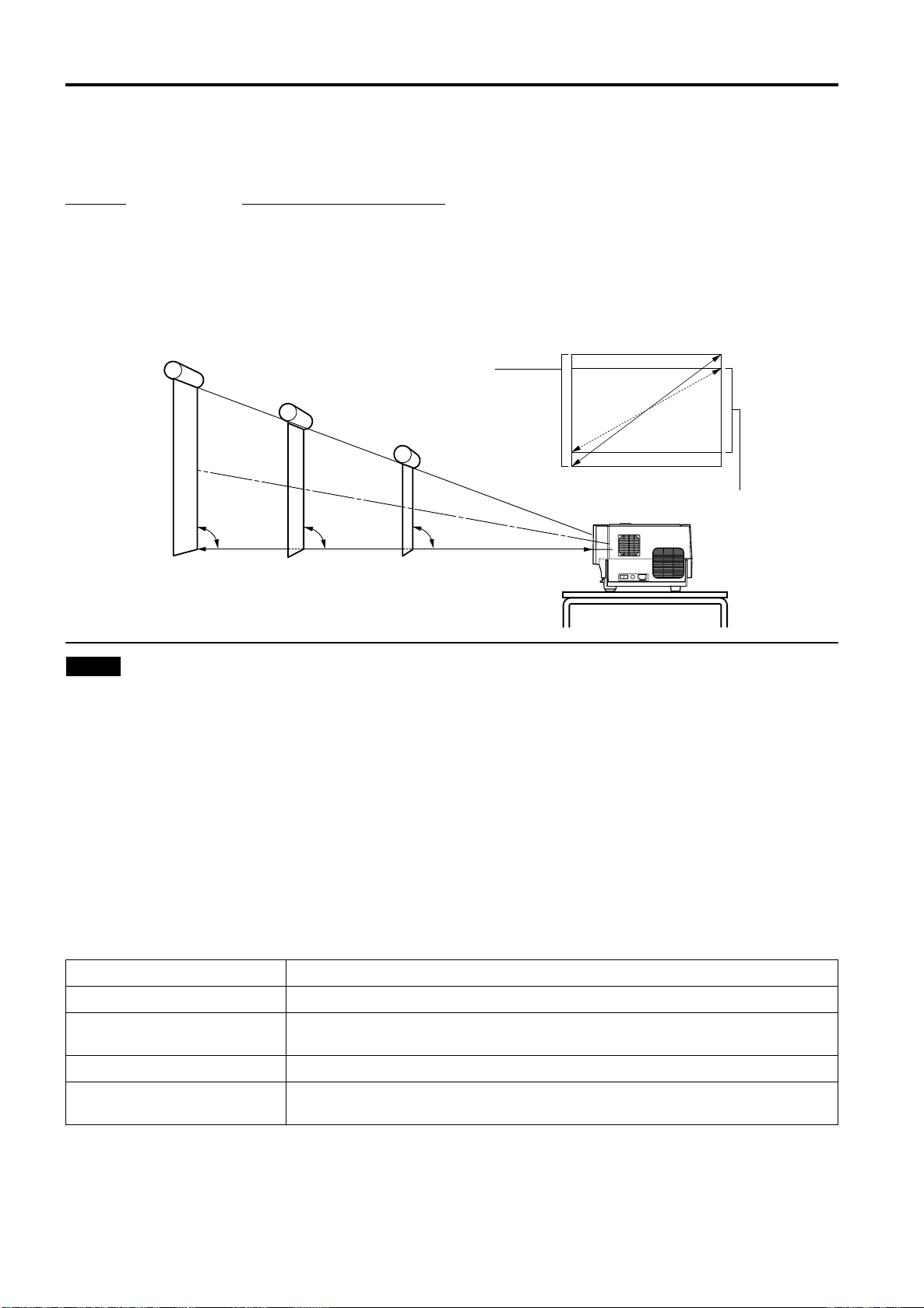
Projection Distance and Screen Size
• The range of projection distances that can be focused depends on the lens unit (optional) to be used. When the aspect ratio
of the screen is 4:3, the range is as follows and you need to install the projector within this range.
Lens type
GL-M2910G 0.77 m to 4.03 m
GL-M2915SG 1.76 m to 4.50 m
GL-M2920ZG 2.77 m to 19.71 m
GL-M2930SZG 4.74 m to 29.87 m
*: The value for projection distance is a guide (reference) one. The projected image size may vary depending on the
manufacturing tolerance of the projection lens.
Screen
To move the Shift position by 50%, set the bottom edge of the projection screen so that it is at the same height as the center of the lens.
Approximate projection distance
Change of projection screen
according to aspect ratio
Screen with 4:3 aspect ratio
Screen with 16:9 aspect ratio
90˚ 90˚ 90˚
Center line of the lens
Notes
• For detailed relationship between projection distances and projection screen sizes, refer to Appendix A. The relationships for
both 4:3 and 16:9 ratios are listed there.
• When installing a screen, use a 4:3 aspect-ratio picture.
• (A 16 : 9 aspect-ratio picture is projected based on the width of the range in which a 4:3 aspect-ratio picture is projected.)
• The diagonal length of a 16:9 aspect-ratio screen is about 91.8% that of a 4:3 aspect-ratio screen. This value is only a guide
(reference).
• If sunlight or lamp light strikes the projection screen directly, the picture tends to become pale and dim. Use a curtain or
other means to shield the light.
• Set the projector horizontally on a surface that is within the range of adjustable angles (up/down adjustment angle: +7° ;
horizontal adjustment angle: ±1.5°).
• If the keystone is adjusted, the projected screen becomes smaller.
• When hanging from the ceiling, use a dedicated hanging fixture (not supplied).
■ Optional Lenses
This projector does not include a lens. You can select one of the optional lenses to adjust the projection distance. Please ask
your authorized dealer or service center to install the lens.
Lens model Function
GL-M2910G Powered focus for rear projection, short focal length (subject ratio 1:1), 0% influence.
GL-M2915SG
GL-M2920ZG Powered zoom/powered focus lens (subject ratio 2:1-3:1), 50% influence.
GL-M2930SZG
Powered focus, short focal length (subject ratio 1.5:1), powered image adjustment (2%
zoom), includes manual vertical shift function, 30%-55% influence
Powered zoom/powered focus long focal length lens (subject ratio 2.9:1-5.5:1), includes
manual vertical shift function, 30%-55% influence.
18
Page 21
Installing the Projector
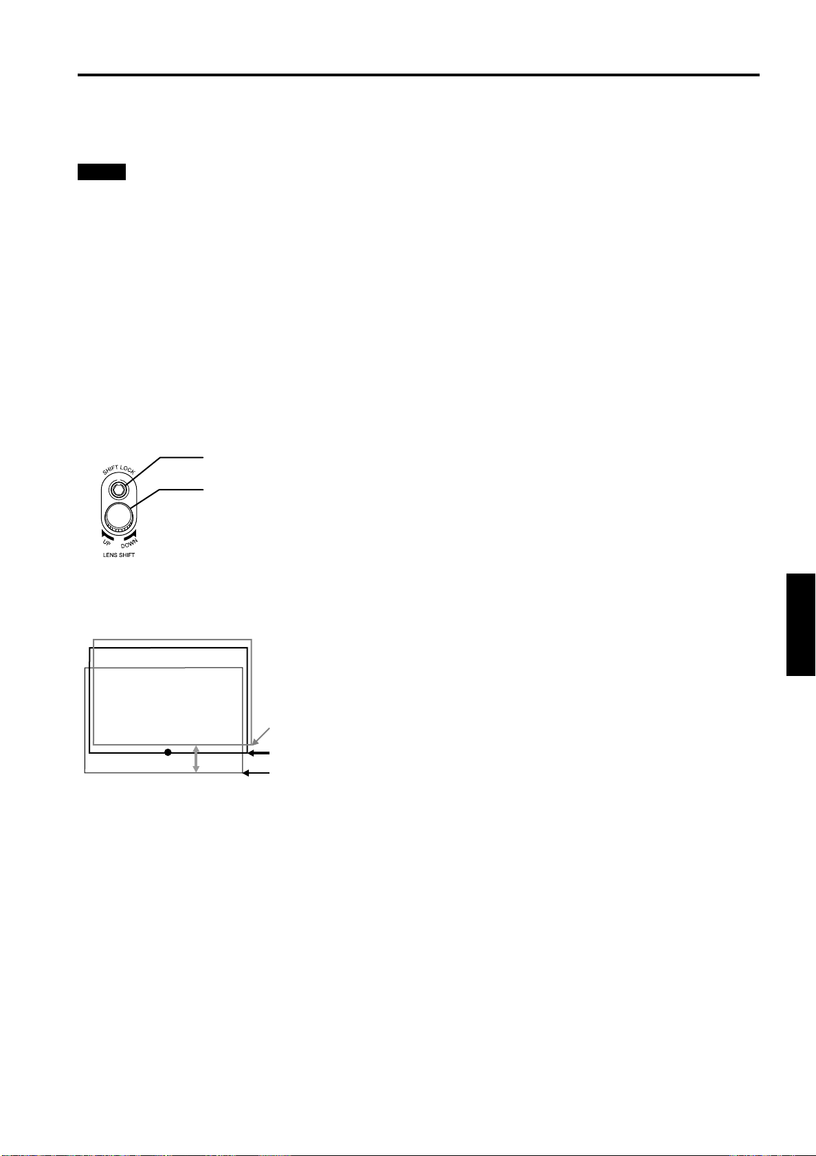
Setting the Amount of Lens Shifting
When the lens unit (optional) with the lens shifting function is used, the projected screen can be shifted up and down in
position.
Notes
• The amount of shifting is within the range of approx. 30% to 55%.
• After finishing the lens shift setting, tighten the SHIFT LOCK fixing bolt firmly so that the lens will not move.
Turn the cap on the top of the projector to open it.
1
Loosen the SHIFT LOCK fixing bolt.
2
Use the hex. wrench supplied.
Rotate the LENS SHIFT knob to adjust the position (shift amount) of the projected
3
screen.
Rotate it to the right: The lens shifts upward.
Rotate it to the left: The lens shifts downward.
Tighten the SHIFT LOCK fixing bolt firmly.
4
Use the hex. wrench supplied.
Turn the cap to close it.
5
SHIFT LOCK fixing bolt
LENS SHIFT knob
■ Projected screen position image by amount of shift
* The projected screen position can only shift in an up-and-down direction.
The illustration shows the screen shifted sidewise for the purpose of explanation.
Approx. 55%
Approx. 50%
Approx. 30%
ENGLISHDEUTSHFRANÇAISITALIANOESPAÑOL
19
Page 22
Installing the Projector
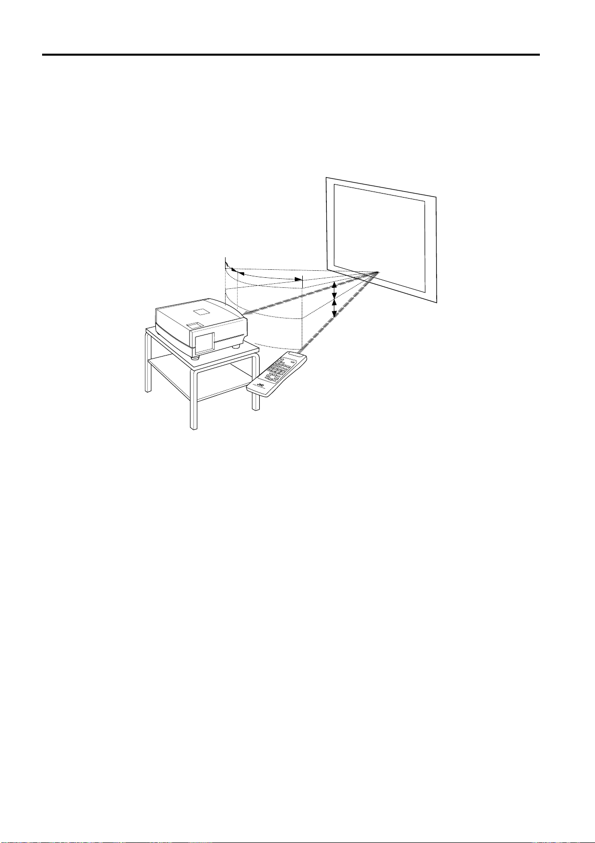
Effective Range and Distance of the Remote Control Unit
The remote control unit can be used as either a wireless remote control unit or a wired one.
Using as a wireless remote control unit
■
Aim the remote control unit toward the remote sensor on the front or the rear of the projector.
The operable distance of the remote control unit is about 10 m for direct reception. The remote control unit can be used by
having it reflected on the screen. In this case, the total distance of “A+B” should be about 10 m or less. The operable angles
of the remote control unit are 15° right and left, and 15° up and down.
Screen
15˚
15˚
Projector
A
15˚
15˚
B
Remote control unit
20
Page 23
Installing the Projector
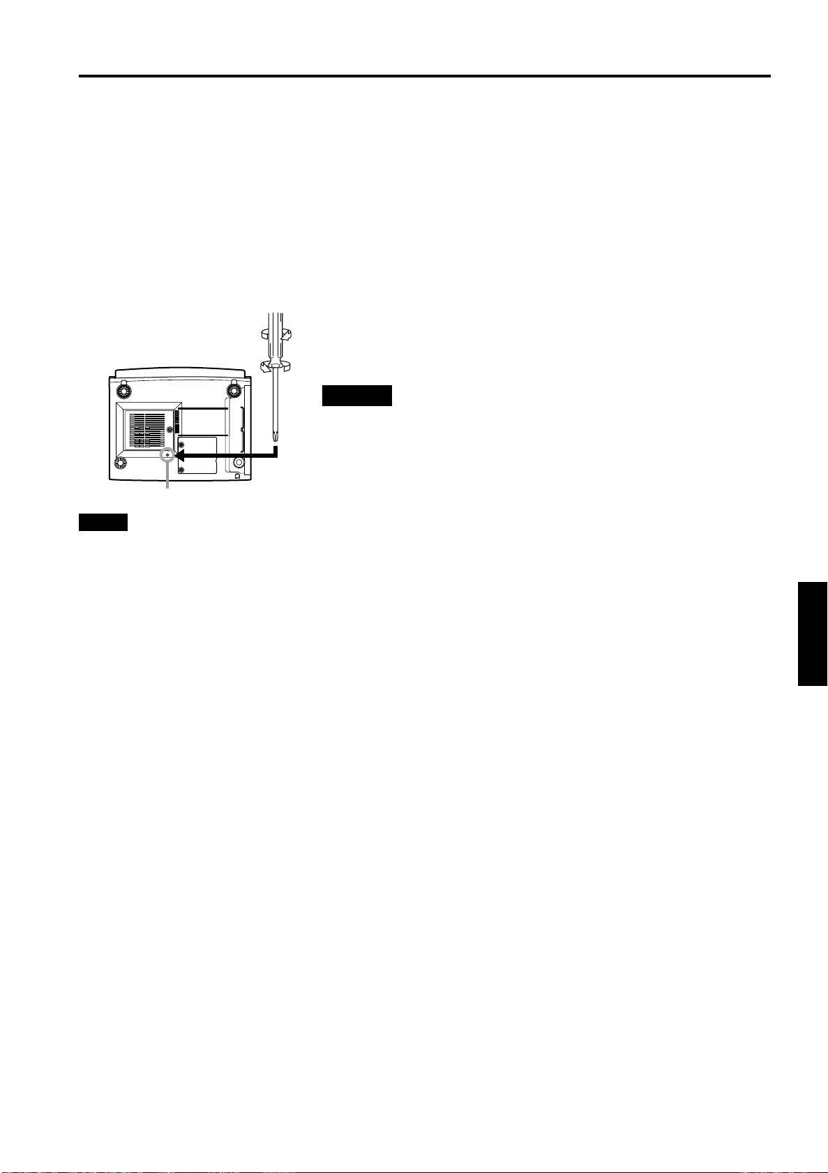
Setting the Position Selecting Screw for Ceiling Mounting
When using the projector in an upside-down, ceiling-mounted position (inverted top-to-bottom and right-to-left), the “position
selecting screw for ceiling mounting” must be turned to switch to ceiling mounting.
This will correct variance in color images (shading), which otherwise would occur in ceiling mounting.
To revert to normal desktop setting, turn the “position selecting screw for ceiling mounting” back to the initial position (factoryshipped).
When using the projector in an upside-down, ceiling-mounted position:
Turn the “position selecting screw for ceiling mounting” fully counterclockwise (until it is turning idly).
To again use the projector in a normal desktop setting:
Turn the “position selecting screw for ceiling mounting” fully clockwise (until it firmly tightens).
For normal desktop mounting:
Turn the screw clockwise.
For upside-down, ceiling-mounting:
Turn the screw counterclockwise.
CAUTIONS
•To ceiling-mount and adjust the projector, special expertise and technique are
necessary. Be sure to ask your dealer or a specialist to perform this work.
•To turn the “position selecting screw for ceiling mounting”, use a Phillips
screwdriver with a 30-mm or longer shank.
The screw is located in the hole shown in the illustration.
Position selecting screw for ceiling mounting
Note
• When using the projector in a ceiling-mounted position, you should reverse the projected image by changing the settings of
Right Left rev. and Top Bottom inv. menus. For details, refer to page 54. You can also change these settings without
receiving a video signal. In this case, refer to “Menu Transition Diagram in No signal Menu Mode” on page 38.
When installing (adjusting/setting) the unit
• When using “Top Bottom inv.” on the “Options” menu, reset the unit by following the procedure below.
• This reset procedure must be performed before operating the unit.
1. Change the “Top Bottom inv.” Setting on the “Options” menu.
2. Press the OPERATE button to enter the unit into the stand-by mode.
3. Press the OPERATE button again to turn on the unit.
• Adjust the focus after projecting a picture for 30 minutes or longer.
ENGLISHDEUTSHFRANÇAISITALIANOESPAÑOL
21
Page 24
Connecting to Various Devices
Before connection, be sure to turn off the projector and connected devices.
Read the manual which comes with each device thoroughly.
Signals that Can Be Input to the Projector
The following signals can be input to the projector:
■ Video signals
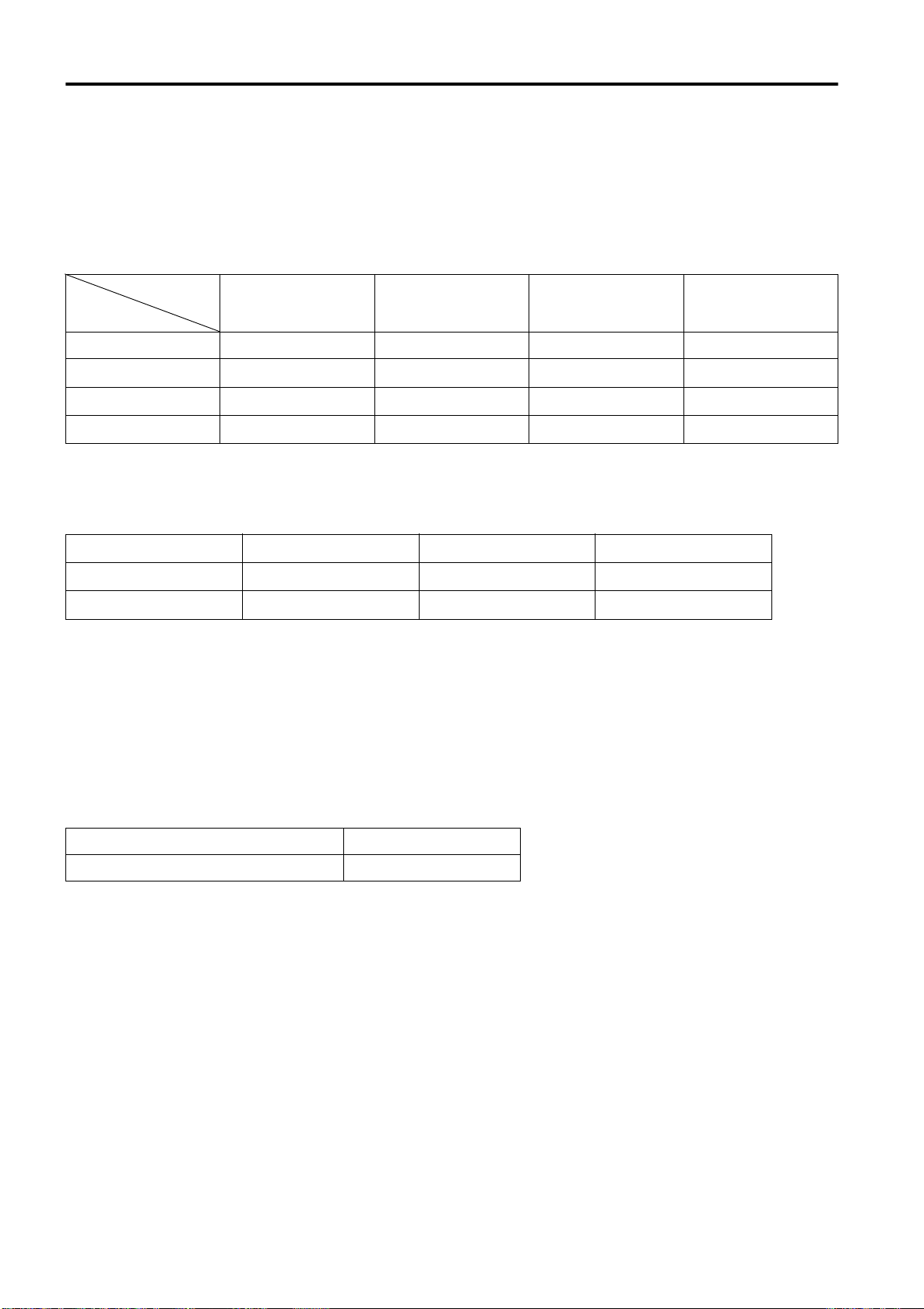
(1) Response to color systems
Color systems
NTSC NTSC4.43 PAL SECAM
Input terminal
VIDEO ‡‡‡‡
Y/C ‡
/B-Y, PR/R-Y ‡*
B
Y, P
G, B, R, H/CS, V ‡*
2
2
‡*
‡*
‡*
1
2
2
‡ - - - - -
2
‡*
‡*
2
‡*
‡*
2
2
*1:Responds if Y/C output is available.
, PR” / “Y, B-Y, R-Y” / “G, B, R, H/CS, V”) conform to the signal timing
*2:Signifies that component signals (“Y, P
B
(synchronization and video period) of each color system. The color systems are used for convenience only.
(2)
Response to double density (*3), high-vision signals
Input terminal
Y, P
/B-Y, PR/R-Y
B
G, B, R, H/CS, V
4
NTSC*
‡‡‡
‡‡‡
NTSC*
5
High-vision signal
*3:Signals whose density of scanning lines/field is twice as high.
*4:Responds to signals whose horizontal scanning frequency is 31.5 kHz. NTSC can be made twice as dense by a line
doubler (separately available: recommended article). Also, possible to respond to fully-specified, decoded
wide-clear-vision signal and decoded 525P progressive signal.
*5:Responds to signals whose horizontal scanning frequency is 33.5 kHz. PAL can be made twice as dense by a line doubler
(separately available: recommended article).
(3) Response to DTV-format signals
/B-Y, PR/R-Y, G, B, R, H/CS, V input terminal.
DTV-format signals (480i, 480p, 720p, 1080i) can be input to the Y, P
B
■ Computer signals
Signals with the following scanning frequencies can be input to the PC 1 or PC 2 (G, B, R, H/CS, V) and DVI terminals.
Horizontal scanning frequency 15kHz - 105kHz
Vertical scanning frequency 50Hz - 100Hz
Be sure that the computer to be used suffices the following conditions:
• The computer has the video signal output port.
Be sure that the computer has the video signal output port by reading the instruction book of the computer.
The video signal output port is generally called as “RGB port”, “monitor port”, or “video port”. If the computer-monitor hybrid
type or note type is used, it may need to prepare for an external output port. Also, there will be the type to which an external
output port cannot be installed.
• DVI input
During DVI input, depending on the computer settings, there may be no signal input or an error may occur (blue screen).
If this happens, turn off the power to both the projector and the computer, and then turn the projector back on before turning
the computer on again. Then correctly set the computer's graphic board.
• The resolution and the scanning frequencies are within the range specified in the table on page 23.
Be sure that the resolution and the scanning frequencies of the video signal are within the range. A video signal out of range
cannot be used. (Even signals out of the range could be projected. However, it may not sharp enough. On the other hand,
even some of the signals within the range may require adjustment depending on the video board used.)
When a signal other than listed in the table on page 23 is input, the image could be partially erased or an unneeded fold-over
image could appear.
Even signals in the frequency range that can be input may not be displayed normally depending on the type of the signal.
) and G on Sync signals cannot be handled depending on the devices connected.
Composite sync (C
S
22
Page 25
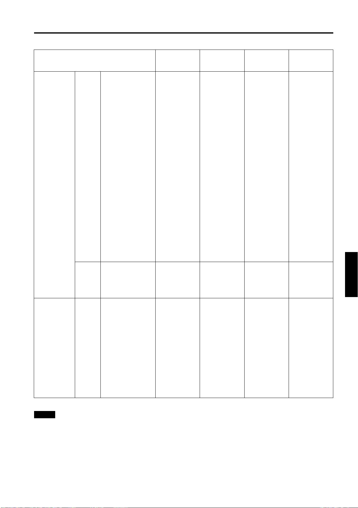
■ Allowable input signals
Connecting to Various Devices
Horizontal res-
Signal
PC system PC98 VESA350 640 350 37.86 84.13
PC/AT PC98 640 400 24.83 56.42
DOS/V VGA 60Hz* 640 480 31.47 59.94
DVI* VGA 72Hz* 640 480 37.86 72.81
VGA 75Hz* 640 480 37.50 75.00
VGA 85Hz* 640 480 43.27 85.01
SVGA 56Hz* 800 600 35.16 56.25
SVGA 60Hz* 800 600 37.88 60.32
SVGA 72Hz* 800 600 48.08 72.19
SVGA 75Hz* 800 600 46.88 75.00
SVGA 85Hz* 800 600 53.67 85.06
XGA 43Hz* 1024 768/2 35.52 43.48
XGA 60Hz* 1024 768 48.36 60.00
XGA 70Hz* 1024 768 56.48 70.07
XGA 75Hz* 1024 768 60.02 75.03
XGA 85Hz* 1024 768 68.68 85.00
SXGA 43Hz* 1280 1024/2 46.43 43.44
SXGA 60Hz* 1280 1024 63.98 60.02
SXGA 75Hz* 1280 1024 79.98 75.03
SXGA 85Hz* 1280 1024 91.15 85.02
UXGA 60Hz 1600 1200 75.00 60.00
Mac MAC13 640 480 35.00 66.67
MAC16 832 624 49.73 74.55
MAC19 1024 768 60.24 74.93
MAC21 1152 870 68.68 75.06
Video system Video HDTV (1035i) 60Hz 33.75 60.00
HDTV (1035i) 59Hz 33.72 59.94
480p 720 483 31.47 59.94
720p 60Hz 1280 720 45.00 60.00
720p 59Hz 1280 720 44.96 59.94
1080i 60Hz 1920 1080/2 33.75 60.00
1080i 59Hz 1920 1080/2 33.72 59.94
1080 24sF 1920 1080 27.00 24.00
NTSC 15.734 60
PAL 15.625 50
SECAM 15.625 50
olution
Hor [Pixels]
Vertical resolu-
tion
Ver [Lines]
Horizontal fre-
quency
H [kHz]
Vertical fre-
quency
V [Hz]
ENGLISHDEUTSHFRANÇAISITALIANOESPAÑOL
* A signal that can be input by DVI (V-sync 85Hz is not supported.)
Notes
• The resolution for the input signals is listed in the above table.
• Even signals in the frequency range that can be input may not be displayed normally depending on the type of the signal.
• When a signal other than listed above is input, the image could be partially erased or an unneeded fold-over image could
appear.
• Some signals other than listed above can be displayed. But they may require adjustment.
• Even some of the signals listed above may require adjustment depending on the video board used.
) and G on Sync signals cannot be handled depending on the devices connected.
• Composite sync (C
• The VGA signal of the PC system could be displayed in 480p mode of the VIDEO system. (In this case, the projector enters
video menu mode when the MENU button is pressed.)
S
23
Page 26
Connecting to Various Devices
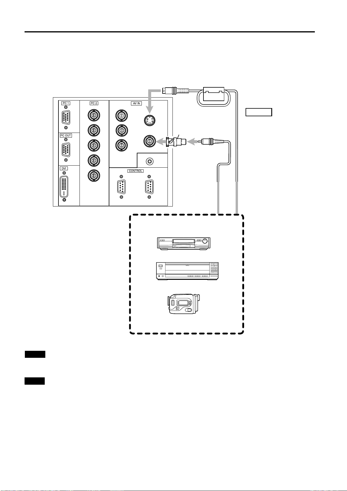
Connecting to Video Devices
Before connection, be sure to turn off both the projector and video device.
• Read thoroughly the manual that comes with each video device.
• Use the supplied video cable. An video cable with an S-video (Y/C) terminal is not supplied.
R
G
B
H
V
IN
Y
P
B/B-Y
P
R/R-Y
REMOTE
IN OUT
Y/C
VIDEO
BNC-RCA conversion
plug (accessory)
To VIDEO
Video cable
To AV IN
To Y/C
S-video cable
(separately available)
(accessory)
Video devices
• VCR (Video cassette recorder)
• Laser videodisc player
• Camcorder
Notes
• Connect a composite image signal output device or Y/C (S-video) image output device.
• When connecting the S-video cable, refer to “How to attach the ferrite core” on page 29.
Memo
• When connecting a video device, use a TBC along with it, or one which has a built-in TBC.
• Use of an extension cable to connect a video device and the projector could cause video degradation.
• When a signal with much jitter is reproduced on a VCR, or special-effect playback is performed, the upper part of the image
or the image itself may be erased or distorted.
24
Page 27
Connecting to Various Devices
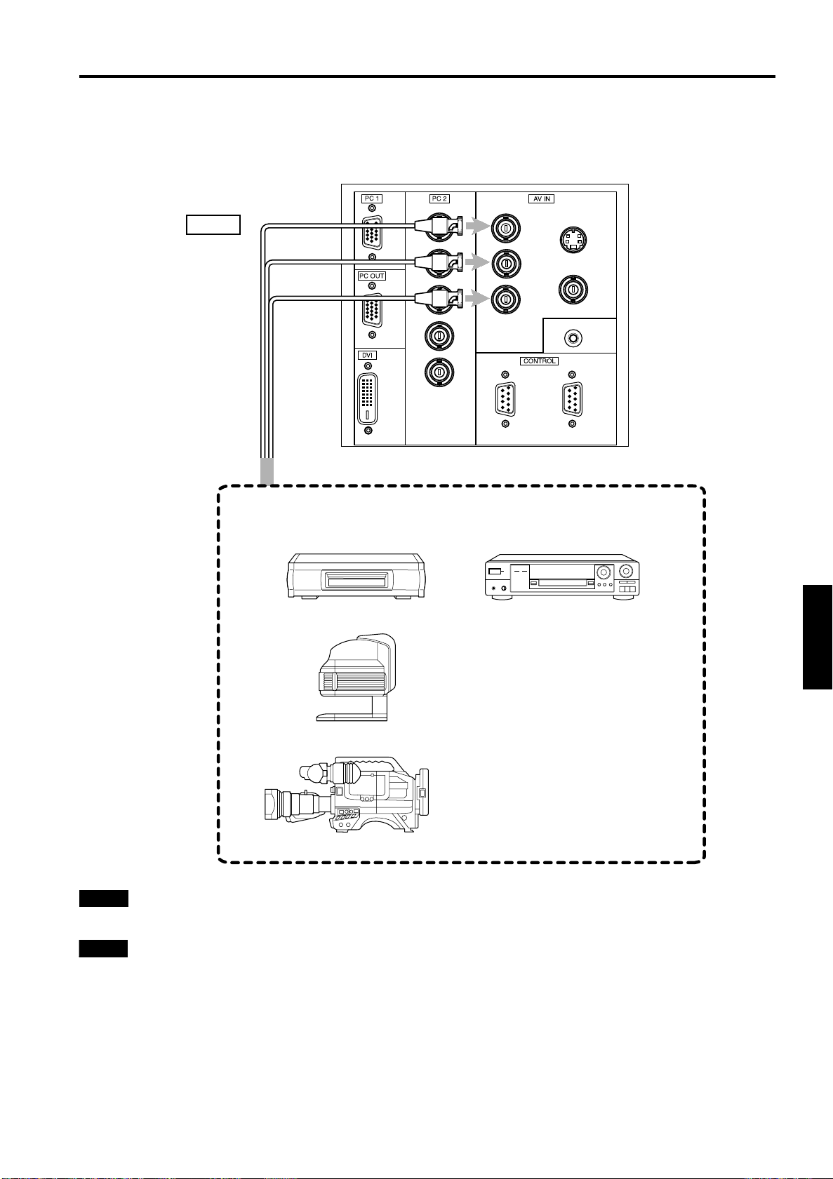
Connecting to Hi-Vision Devices/DVD Players
Before connecting, be sure to turn off both the projector and Hi-Vision devices/DVD players.
• Thoroughly read the manual that comes with each Hi-Vision device or DVD player.
• Use separately available BNC cables to connect Hi-Vision devices and DVD players.
To Y
To PC 2
To PB/B-Y
To P
R/R-Y
R
G
B
Y
P
P
B/B-Y
R/R-Y
Y/C
VIDEO
BNC cable
(separately available)
Hi-Vision devices
• W-VHS VCR
• Text/video camera
H
REMOTE
V
IN
IN OUT
DVD player
ENGLISHDEUTSHFRANÇAISITALIANOESPAÑOL
• Hi-Vision video camera
Note
• Connect a component signal output device or DTV-format signal output device.
Memo
• Other devices with component signal output terminals (DVD player (NTSC), etc.) can be connected.
(*DVD: Digital Video Disc)
• DTV-format signals (480i, 480p, 720p, 1080i) can be input. For DTV-format signals which can be handled, refer to “Video
signals” on page 22.
25
Page 28
Connecting to Various Devices
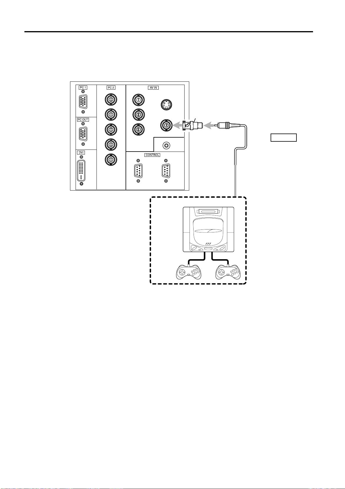
Connecting to Other Devices
Before connection, be sure to turn off both the projector and other devices to be connected.
• Read thoroughly the manual that comes with the device to be connected.
• Use the supplied video cable or the cable supplied with the game device.
R
G
B
H
V
IN
Y
P
P
B/B-Y
R/R-Y
REMOTE
Y/C
BNC-RCA conversion
plug (accessory)
VIDEO
To VIDEO
To AV IN
Cable supplied with the
IN OUT
game device, or supplied
video cable
Game device, etc.
26
Page 29
Connecting to Various Devices
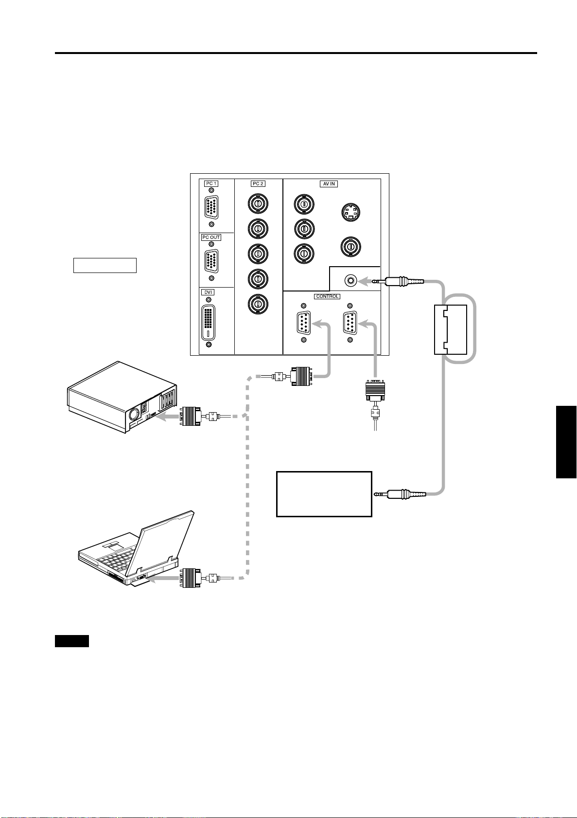
Connecting to Devices which Control the Projector
Before connection, be sure to turn off both the projector and devices to be connected.
• Read thoroughly the manual that comes with each device to be connected.
• By connecting a computer to the RS-232C terminal, you can control the projector. Also, you can make an infrared remote
sensor extension unit and connect it to the REMOTE terminal of the projector.
* Obtain connection cables as required. Use a reverse connection cable.
* For details, refer to “RS-232C external control” on page 74.
* For further details, consult your dealer or an authorized service center.
TO CONTROL
• Desktop type
IN
To RS-232C connector
R
G
B
H
V
Y
B/B-Y
P
P
R/R-Y
IN OUT
To RS-232C connector
Y/C
VIDEO
REMOTE
*
To REMOTE terminal
ENGLISHDEUTSHFRANÇAISITALIANOESPAÑOL
Infrared remote sensor
• Note type
extension unit
(Needs to be made)
RS-232C reverse
connection cable
(separately available)
* By directly connecting the OUT terminal
to the second DLA-G150CLE IN
To RS-232C connector
terminal, a number of DLA-G150CLE
units can be controlled by a single
computer.
Note
• When connecting the cable to the REMOTE terminal, refer to “How to attach the ferrite core” on page 29.
27
Page 30
Connecting to Various Devices
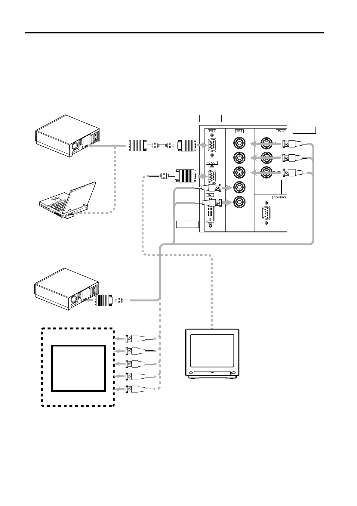
Connecting to Computer Devices
Before connection, be sure to turn off both the projector and computer devices.
• Read thoroughly the manual that comes with each device.
■ Connection to an IBM PC or IBM-compatible computer
• Use the supplied personal computer connection cable. Also, prepare cables required for connecting the devices
connected.
• Desktop type
To PC 1
To monitor
connector
• Notebook type
* There are some notebook types which
do not allow the computer’s LCD to work
if an external display is connected. With
such a notebook computer, the LCD
display and external display output
need to be switched.
Personal Computer
connection cable (supplied)
To PC 1
To PC OUT
Cable
supplied
with the
To H/Cs
display (or
separately
available)
To V
(D-sub 3row 15-pin)
To PC 2
To PC 2
Separate cable (separately available)
R
G
B
H
V
IN
Y
P
B/B-Y
P
R/R-Y
IN
To P C 2
To R
To G
To B
• Desktop type
• RGB output devices
Laser video disc
player, etc.
To monitor connector
To R
To G
To B
POWER
To H/Cs
Display monitor
To V
* When a display monitor is connected to
the PC OUT terminal, you can view the
video from the computer on the monitor.
28
Page 31

Connecting to DVI
Y
P
P
Before connection, be sure to turn off both the projector and computer devices.
• Read thoroughly the manual that comes with each device.
Connecting to Various Devices
R
G
B
H
DOS/V
(DVI VIDEO BOARD)
Note
• Other connections are the same as in the connection example for IBM PC or IBM compatible PCs.
DVI (DVI-D 24pin Cable)
(Available separately)
IN
V
IN
How to attach the ferrite core
Attach the ferrite core when using the S-video cable or infrared remote sensor extension unit which are sold separately.
However, use a cable that can be wound once.
Release the stopper at each end and
1
open the ferrite core.
Stoppers
Wind the cord around the ferrite core.
2
Attach the ferrite core about 3 cm from the end of the
cord.
Wind the cable once.
ENGLISHDEUTSHFRANÇAISITALIANOESPAÑOL
Close the ferrite core with the cord
3
inside until you hear it click shut.
Note
• When connecting, connect the terminal which is at the
ferrite core end of the cord to the projector.
Click!
29
Page 32

Connecting to Various Devices
Connecting the Power Cord
After all devices have been finished being connected, connect the supplied power cord. At this time, do not yet turn on the
MAIN POWER switch.
Insert the supplied power cord into the
R
E
T
N
E
U
N
E
O
M
E
D
I
V
C
P
T
I
X
E
E
T
A
R
E
P
O
T
E
S
E
E
R
P
N
O
T
E
S
ID
Y
P
E
H
M
K
E
PT
M
A
L
N
W
O
D
P
U
Power cord (supplied)
for European continent countries
1
power input terminal of the projector.
Insert the main plug of the supplied
2
power cord into a suitable wall outlet.
Ferrite core
for United Kingdom
CAUTIONS
To prevent fire and electric shock, observe the
following:
• When you do not use devices, pull out their power cords
from wall outlets.
• Do not connect the devices with power cords other than
those supplied.
• Do not use mains voltage other than the power voltage
indicated.
• Do not scar, damage, or work on the power cords. Also, do
not put a heavy object on, heat, or stretch the power cords,
otherwise they may be damaged.
• Do not insert or pull out the plugs with a wet hand.
Removing the Lens Cap
for European
for United Kingdom
continent countries
Note
• The power cord for the United Kingdom is only included as
a special accessory when shipped to the
United Kingdom
. It
is not included when shipped to European continent
countries.
CAUTIONS
• Since the power requirement of the projector is high, insert
the power plug directly into a wall outlet.
• Use the supplied power cord with the ferrite core only.
• Do not remove the ferrite core from the supplied power
cord; Otherwise, there may be a possibility that a harmful
interference occurs.
Remove the lens cap before using the projector.
Notes
• The lens cap is supplied with the lens unit (optional). It
should be attached to the lens when the projector is not
used.
• Do not operate the projector with the lens cap attached.
Doing so can deform the lens cap because of the heat. A
metallic lens cap can get hot and cause injury.
30
Page 33

Basic Operations
■ Lamp control settings
After turning the power on, first perform the lamp control settings on the setting menu referring to “Setting and Adjusting Other
Functions (OPTIONS)” on page 54.
There are 3 modes in the lamp control settings.
1: NORMAL MODE (Normal)
Used as a normal lamp.
The projector is set to “Normal” mode at the time of purchase.
* “Lamp replacement” appears on the screen when the lamp use time exceeds 1000 hours.
2: LIGHT POWER CONTROL MODE (LPC)
Automatically controls the power used by the lamp and increases it in steps. When this mode is used, the brightness
starts at approximately 70%. The decrease in brightness is slower than in “Normal” mode and this mode is best suited
when using the projector continuously for long periods of time.
* “Lamp replacement” appears on the screen when the lamp use time exceeds 2000 hours.
3: LIGHT OUTPUT CONTROL MODE (LOC)
The brightness can be set in seven levels (-6 to 0). Since the brightness can be set in steps, this is the mode best suited
for adjusting multiple screens. This setting can also be changed while the projector is being used. To change the setting,
choose LOC with the 5/∞ cursors and choose the level with the 2/3 cursors.
* “Lamp replacement” appears on the screen when the lamp use time exceeds 2000 hours.
The lamp replacement time is different for the 3 modes.
1: NORMAL MODE (Normal) ... 1000 hours
2: LIGHT POWER CONTROL MODE (LPC) ... 2000 hours
3: LIGHT OUTPUT CONTROL MODE (LOC) ... 2000 hours
* These lamp replacement times are only a rough guide as to how long the lamp will last if these modes are used from the
beginning. These are not guaranteed service lives.
Notes
• Although the LIGHT OUTPUT CONTROL MODE (LOC) and LIGHT POWER CONTROL MODE (LPC) electrically control
the brightness of the lamp and extend the replacement time longer than that for the NORMAL MODE, the service life of the
lamp is approximately 1000 hours.
• The lamp will gradually become less bright in each mode.
Since the lamp may become less bright quickly in some usage environments, replace the lamp if you notice that it is no
longer bright even if the lamp has not yet reached the end of its life.
• Mode settings
* If the projector is not put in stand-by mode or turned off after the lamp has been used continuously in the normal mode for
more than 1000 hours (but less than 2010 hours), it can be used for “up to 2010 hours”.
However, if the projector is put in stand-by mode or turned off, it can not be turned back on again.
* If the projector is put in stand-by mode or turned off after the lamp has been used in the light output control mode or light
power control mode for more than 2000 hours (but less than 2010 hours), it can not be turned back on again.
However, if the projector is not put in stand-by mode or turned off, it can be used for “up to 2010 hours”.
* If the projector is used in the light output control mode or light power control mode for more than 1000 hours, and then
switched to the normal mode, put in stand-by mode or turned off, it can not be turned back on again.
After performing the above settings, perform the necessary settings.
ENGLISHDEUTSHFRANÇAISITALIANOESPAÑOL
31
Page 34

Basic Operations
■ Projector’s buttons
LAMP TEMP
HIDE
KEYSTONE
PRESET
EXIT ENTER
N
W
O
D
STAND BY
OPERATE
PC
VIDEO
MENU
R
TE
N
E
U
O
MEN
E
ID
V
C
P
T
XI
E
E
AT
ER
OP
T
SE
E
RE
P
N
O
T
E
ID
YS
P
H
KE
EM
T
P
AM
L
P
U
STAND BY indicator
OPERATE indicator
OPERATE button
The following describes the basic procedure for normal use
of the projector.
1. Turning on the Power
Turn on the MAIN POWER switch.
1
ON [ ❙❙❙❙ ]:The main power turns on and the STAND BY
indicator comes on.
Projector’s indicator
STAND BY
OPERATE
Press the OPERATE button for one
2
second or more.
• The OPERATE indicator lights and the projected
screen slowly appears.
Remote control unit
OPERATE
or
Projector
STAND BY
OPERATE
Notes
• After the power is turned on, the image may be jumbled for
a few seconds, but this is not a malfunction.
• After the indicator comes on, it can take a minute or so for
the lamp to warm up and operate consistently.
■ Turning off the Power
■ Remote control unit
QUICK
ALIGN.
W
W
SCREEN
SCREEN
S
S
PC1 PC2
KEYSTONE
HIDE
FREEZE
COMP
DVI
T
T
DIGITAL
ZOOM FOCUS
ZOOM
W
W
PRESET
RM-M160 REMOTE CONTROL UNIT
OPERATE
VIDEO
Y/C
MENU
ENTEREXIT
OPERATE button
Press the OPERATE button for one
1
second or more.
• The STAND BY indicator changes to blinking, and the
projector goes into cool-down mode. The cool-down
mode will continue for approximately 120 seconds.
Remote control unit
OPERATE
Projector
STAND BY
OPERATE
(Blinking)
Note
• The OPERATE button will not work for approximately 1
minute from when the light-source lamp is turned on. Use
the button after approximately 1 minute.
Turn off the MAIN POWER switch after
2
the STAND BY indicator changes to
steady on.
OFF [‡‡‡‡]:The MAIN POWER switch turns off and the
STAND BY indicator goes off.
Projector
STAND BY
OPERATE
32
CAUTION
• Do not turn off the MAIN POWER switch during cool-down
mode (the STAND BY indicator blinking). Turn it off after
the STAND BY indicator becomes on (stand-by mode).
Page 35

Basic Operations
■ Projector’s buttons
LAMP TEMP
HIDE
KEYSTONE
PRESET
EXIT ENTER
STAND BY
OPERATE
PC
VIDEO
MENU
PC button
VIDEO button
■ Remote control unit
QUICK
ALIGN.
W
W
SCREEN
SCREEN
S
S
PC1 PC2
KEYSTONE
HIDE
FREEZE
COMP
DVI
T
T
DIGITAL
ZOOM FOCUS
ZOOM
W
W
PRESET
RM-M160 REMOTE CONTROL UNIT
OPERATE
VIDEO
MENU
ENTEREXIT
Y/C
PC button
VIDEO button
ZOOM button
■ Language display
The display languages of the menus, direct buttons
(DIGITAL ZOOM, KEYSTONE, etc) and messages is set to
“ENGLISH” when the projector is bought. The display
language can be selected from the following 6 languages:
“ (Japanese)”, “English (English)”, “Deutsch
(German)”, “Español (Spanish)”, “Italiano (Italian)” and
“Français (French)”. (Refer to page 46.) However, some
words (VIDEO, NTSC, Quick Alignment, etc) are only
displayed in English.
2. Select the Input source to be Projected
Press the VIDEO button or the PC button to switch the input.
• Each time you press either button, the selected input
changes as follows. The selected name appears on the top
right of the image on the screen for five seconds. (Called
line display.)
When selecting an image device connected to the
AV IN (VIDEO, Y/C or COMP) terminal:
Projector
Press VIDEO.
The input mode changes as follows every time the button is
pressed.
VIDEO ↔ Y/C ↔ COMP
Remote control unit
Press the “VIDEO”, “Y/C” or “COMP” button.
VIDEO: The image from the VIDEO input terminal on the
side of the unit is projected.
Y/C: The image from the Y/C input terminal on the side of
the unit is projected.
/B-Y, PR/R-Y)
COMP: The image from the COMP (Y, R
input terminal on the side of the unit is projected.
* When there is no signal from the selected input terminal
(No signal), “No Input” is displayed.
When selecting a device such as a computer
which is connected to the PC1, PC2 or DVI
terminal:
Projector
Press PC.
The input mode changes as follows every time the button is
pressed.
PC1 ↔ PC2 ↔ DVI
Remote control unit
Press the “PC1”, “PC2” or “DVI” button.
PC1: The image from the PC1 input terminal on the side of
the unit is projected.
PC2: The image from the PC2 input terminal on the side of
the unit is projected.
DVI: The image from the DVI input terminal on the side of
the unit is projected.
* When there is no signal from the selected input terminal
(No signal), “No Input” is displayed.
Remote control unit Projector
SCREENSSCREEN
FREEZE
COMP
S
PC1 PC2
VIDEO
DVI
Y/C
B
PC
VIDEO
ENGLISHDEUTSHFRANÇAISITALIANOESPAÑOL
[Screen display]
VIDEO
QUICK ALIGNMENT
Line Display
PC 1
PC 2
Y/C
VIDEO
COMP
DVI
* To show the line display (Y/C, VIDEO, COMP, PC1, PC2 or
DVI) or not is selectable by the menu. Refer to “Setting and
Adjusting Other Functions (OPTIONS)” on page 54.
Note
• When no image signal is input to the selected input
terminal, the message “No Input” is displayed on the
screen. (Refer to page 67.)
33
Page 36

Basic Operations
■ Projector’s buttons
LAMP TEMP
KEYSTONE
PRESET
PRESET button
EXIT button
EXIT ENTER
■ Remote control unit
QUICK
ALIGN.
W
SCREEN W/S button
FOCUS +/– button
ZOOM T/W button
PRESET button
EXIT button
W
SCREEN
SCREEN
S
S
PC1 PC2
KEYSTONE
HIDE
HIDE
FREEZE
COMP
DVI
T
T
DIGITAL
ZOOM FOCUS
ZOOM
W
W
PRESET
RM-M160 REMOTE CONTROL UNIT
OPERATE
VIDEO
MENU
ENTEREXIT
STAND BY
OPERATE
VIDEO
MENU
Y/C
3. Adjust the Screen Size (Zooming)
How to adjust the projected screen size differs depending on
the lens unit (optional) you are using.
GL-M2910G (without zooming function):
PC
The projected screen size cannot be changed.
GL-M2915SG/GL-M2920ZG/GL-M2930SZG (with
zooming function):
Adjust the projected screen size with the following buttons on
the remote control unit.
Note
• The function of GL-M2915SG is to adjust the view angle
zooming by 2%. (For fine view angle adjustment)
To enlarge the projected screen size
Press the ZOOM W (Wide) button.
To reduce the screen size
Press the ZOOM T (Tele) button.
Remote control unit
T
DIGITAL
ZOOM
W
4. Adjust Focus
Adjust focus with the following buttons on the remote control unit.
To focus on farther points:
Press the FOCUS + button.
To focus on nearer points:
Press the FOCUS – button.
Remote control unit
FOCUS
5. Setting the Screen Aspect Ratio
Set in accordance with the screen aspect ratio that will be
used. When a screen aspect ratio of 16:9 is used, a 4:3
image can be projected within the screen without using the
zoom function.
When using a 16:9 screen:
Press the “W” button.
When using a 4:3 screen:
Press the “S” button.
Remote control unit
* There is no button on the unit.
* This setting can also be performed from the menu. (Refer
to page 46.)
• When using a screen with a 16:9 aspect ratio
When set to “S” (4:3)
* If a 4:3 image is projected, some
parts of the top and bottom of the
image may not be displayed.
When set to “W” (16:9)
* A 4:3 image will be displayed in full
in the middle of the screen.
W
W
SCREEN
SCREEN
S
S
34
Page 37
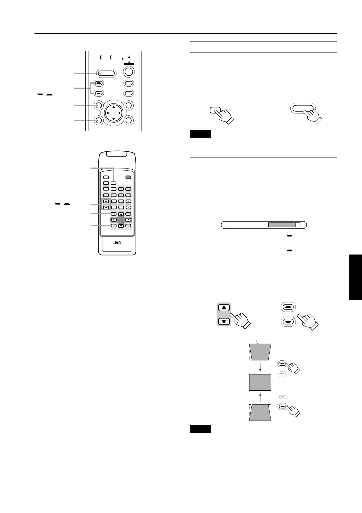
Basic Operations
■ Projector’s buttons
LAMP TEMP
HIDE
HIDE
button
KEYSTONE
/ buttons
KEYSTONE
PRESET
PRESET
button
EXIT
button
EXIT ENTER
■ Remote control unit
HIDE button
KEYSTONE
/ buttons
PRESET button
EXIT button
QUICK
ALIGN.
W
W
SCREEN
SCREEN
S
S
PC1 PC2
KEYSTONE
HIDE
FREEZE
COMP
DVI
T
T
DIGITAL
ZOOM FOCUS
ZOOM
W
W
PRESET
RM-M160 REMOTE CONTROL UNIT
STAND BY
OPERATE
PC
VIDEO
MENU
OPERATE
VIDEO
Y/C
MENU
ENTEREXIT
Turning off Image (HIDE)
Video image can be temporarily turned off.
Press the HIDE button once:
Video image instantly turn off.
Press the HIDE button again:
Video image come on again.
Remote control unit
HIDE
Note
• When the projected image input is changed, the HIDE
function is canceled and the image return.
Projector
HIDE
Removing the Trapezoidal Distortion of
the Image
If the image projected on the screen is distorted in trapezoid
form, correct it with the KEYSTONE buttons on the projector.
When the KEYSTONE button is pressed, “Keystone”
appears on the screen together with the level bar and set
value (–80 to 128). When “15 sec.” is displayed in the menu,
“Keystone” will appear in approximately 15 seconds.
Keystone 123
When you press the KEYSTONE button:
The trapezoid form is corrected as shown in the figure.
When you press the KEYSTONE button:
The top bottom inverted trapezoid form is corrected as
shown in the figure.
* To cancel correction and restore the original screen, press
the PRESET button.
* Press the EXIT button to immediately remove the keystone
display.
Remote control unit Projector
(Adjusted value:0)
ENGLISHDEUTSHFRANÇAISITALIANOESPAÑOL
KEYSTONE
KEYSTONE
Projected image with trapezoidal distortion
KEYSTONE
KEYSTONE
Notes
• The trapezoidal distortion (keystone) can be adjusted from
the option menu. (Refer to page 54.)
• The range of the trapezoidal distortion adjustment is
approximately 20° in the vertical direction.
• Interference patterns may appear on the screen when
adjusting the keystone. This is not a malfunction.
• Depending on the type of signal, some noise may appear in
the picture when the keystone is adjusted.
This is not a malfunction.
35
Page 38

Basic Operations
■ Remote control unit
QUICK
QUICK ALIGN.
button
ALIGN.
W
W
SCREEN
SCREEN
S
S
PC1 PC2
KEYSTONE
RM-M160 REMOTE CONTROL UNIT
HIDE
FREEZE
DIGITAL
ZOOM
PRESET
T
W
OPERATE
COMP
DVI
T
ZOOM FOCUS
W
ENTEREXIT
VIDEO
MENU
Quick Alignment Function
(QUICK ALIGN.)
The Quick Alignment function automatically adjusts (sets)
the screen settings of the image input from the PC1, PC2 or
DVI input terminals. This can only be performed from the
remote control.
Y/C
While projecting an image on the screen, press the QUICK
ALIGN. button on the remote control.
Quick alignment is conducted to obtain best image.
* During the automatic alignment, “Quick Alignment” appears
on the screen, and then disappears when the alignment is
completed.
Remote control unit
QUICK
ALIGN.
[Screen display]
Quick Alignment
Notes
• This only works for the signals input from the PC1, PC2 or
DVI input terminals. It does not work for the signals input
from the AV IN terminal (VIDEO, Y/C or COMP input
terminal).
• The quick alignment function is used to automatically adjust
the “Horizontal and vertical position”, “Phase” and
“Tracking” of the projected image.
• When using the quick alignment function to automatically
adjust the image, use a bright, still-picture. It may not
function correctly on a dark or motion picture. If the results
obtained with the quick alignment function are not
satisfactory, manually adjust the “Horizontal and vertical
position”, “Phase” and “Tracking” of the projected image.
36
Page 39

Basic Operations
■ Remote control unit
QUICK
ALIGN.
HIDE
W
W
SCREEN
SCREEN
FREEZE
S
S
DIGITAL ZOOM
T/W button
PRESET button
EXIT button
FREEZE message
FREEZE inhibit message
PC1 PC2
DIGITAL
KEYSTONE
PRESET
RM-M160 REMOTE CONTROL UNIT
FREEZE
FREEZE
T
ZOOM
W
OPERATE
COMP
DVI
T
ZOOM FOCUS
W
ENTEREXIT
VIDEO
Displaying a Still Picture (FREEZE)
While projecting an image, a still picture is obtained at any
time by using the FREEZE button on the remote control.
When you press the FREEZE button:
“FREEZE” appears on the screen for a few seconds and
then the still picture is shown on the screen. Refer to the
Y/C
FREEZE button
FREEZE message shown on the left of this page.
* To forcibly clear “FREEZE”, press the EXIT button.
When you press the FREEZE button again.
MENU
Cursor buttons
5/∞ / 2/3
The original image resumes.
Remote control unit
FREEZE
Notes
• During freezing, the picture sent from the signal source is
lost.
• If any of the inoperative buttons (“MENU”, “QUICK ALIGN.”,
“KEYSTONE”) are pressed while displaying a still picture,
“FREEZE” is displayed on the screen.
• This function will not work with some signal sources
(UXGA, etc). In this case, the FREEZE inhibit message
appears for a few seconds, as shown on the left. To forcibly
clear this message, press the EXIT button.
Zooming a Part of the Image
(DIGITAL ZOOM T/W)
A part of the image being projected can be digitally magnified up
to four times. When the DIGITAL ZOOM T or W button is
pressed, “Digital zoom” appears on the screen together with the
level bar and magnifying power (
2.5, ×3.2, ×4.0).
×
When “15 sec.” is displayed in the menu,
“Digital zoom” will appear in approximately 15 seconds.
Digital zoom 1.2
• To zoom up or zoom down, press the DIGITAL ZOOM T or
W button on the remote control.
Remote control unit
1.0, ×1.2, ×1.4, ×1.6, ×2.0,
×
T
DIGITAL
ZOOM
W
ENGLISHDEUTSHFRANÇAISITALIANOESPAÑOL
DIGITAL ZOOM inhibit message
D.ZOOM
Moving the zoomed image:
While “Digital zoom” appears on the screen, you can move
the zoomed image with the cursor (5/∞/2/3) button on the
remote control.
5: Upper part of the image will be
displayed.
∞: Lower part of the image will be
displayed.
2: Left side part of the image will
be displayed.
3: Right side part of the image
will be displayed.
Notes
• This function will not work with some signal sources
(UXGA, etc). In this case, the DIGITAL ZOOM inhibit
message appears for a few seconds, as shown on the left.
To forcibly clear this message, press the EXIT button.
• The quality of the zoomed image reduces in comparison
with the original one.
• To return to the original size (
1.0) and original position,
×
press the PRESET button while “Digital zoom” is displayed
on the screen.
37
Page 40

Menu Operations
You can adjust picture quality, set functions, get information on the input video signal, etc. using the menus. From the
following menu transition diagrams, you can see the overall menus and basic button operation in menu mode. Note that there
are three menu modes, No signal menu mode, video menu mode and PC menu mode. When the MENU button is pressed,
the projector enters one of these modes by judging the input signal being received.
■ Menu Transition Diagram in No signal Menu Mode
This is displayed if there is no signal from the selected input terminal.
Main menu in No signal Menu Mode Submenus in No signal Menu Mode
Press 5/∞ to select an item.
Menu
Set up
Options
Language
Information
Sync level
Sync timing
5
Menu
Set up
Options
Language
Information
∞
Menu
Set up
Input
Switcher
5
English
Deutsch
Español
Italiano
Fran çais
5
PC1
CH.0
∞
∞
3 or ENTER
EXIT
3 or
ENTER
EXIT
Press 5/∞ to select an item.
Press 2/3 to set the value.
Set up
Sync level
Sync timing
StdLow High
Press 5/∞ to select an item.
Language
English
Deutsch
Español
Italiano
Fran çais
Options
Language
Information
Lamp time
123 h
■ Quick Reference Guide for No signal Menu Mode
Main Menu in No signal Menu Mode
Set up
Sync level: Low. Std*. High.
Sync timing: 3-5
Options
Flip H: OFF* / ON (Select for upside-down hanging on the ceiling.)
Flip V: OFF* / ON (Select for upside-down hanging on the ceiling.)
RS-232C [bps]: Selectable baud rate (transmission speed). 9600 / 19200*
Sleep time [min]: Selectable sleep times. If no-signal condition continues for the period of selected time
Language Language for on-screen display.
Japanese / English* / German / Spanish / Italian / French
Information
Input: Shows the terminal name selected by the VIDEO or PC button. (Y/C, VIDEO, COMP,
Switcher: Has no meaning. This display currently has no meaning. (“CH.0” is usually displayed to
Lamp time: Accumulated used hours of the light-source lamp.
(Unit: Minutes), the projector enters the stand-by mode. 15 / 30 / 60 / OFF*
PC1, PC2 or DVI)
indicate that it is not being used.)
38
Page 41

■ Menu Transition Diagram in Video Menu Mode
Main menu in Video Menu Mode
Submenus in Video Menu Mode
Menu Operations
Press 5/∞ to select an item.
Menu
Menu
Image adj.
Image adj.
Set up
Set up
Color temp.
Color temp.
Options
Options
Language
Language
Information
Information
5
Image adj.
Image adj.
Set up
Set up
Color temp.
Color temp.
Options
Options
Language
Language
Information
Information
Menu
Menu
Contrast
Contrast
Brightness
Brightness
Color
Color
Tint
Tint
Sharpness
Sharpness
All reset
All reset
5
Position
Position
Gamma
Gamma
Aspect ratio
Aspect ratio
Decoder
Decoder
Tracking
Tracking
Deinterlace
Deinterlace
Phase
Phase
Screen
Screen
HDTV
HDTV
5
Menu
Menu
Image adj.
Image adj.
Set up
Set up
Color temp.
Color temp.
Options
Options
Language
Language
Information
Information
Color temp.
Color temp.
RED
RED
GREEN
GREEN
BLUE
BLUE
Call reset
Call reset
5
Menu
∞
Menu
Image adj.
Image adj.
Set up
Set up
Color temp.
Color temp.
Options
Options
Language
Language
Information
Information
Menu display
Menu display
Line display
Line display
Lamp time display
Lamp time display
Keystone
Keystone
Lamp control
Lamp control
5
Menu
Menu
Image adj.
Image adj.
Set up
Set up
Color temp.
Color temp.
Options
Options
Language
Language
Information
Information
English
English
Deutsch
Deutsch
Español
Español
Italiano
Italiano
Français
Français
Press 5/∞ to select an item.
Press 2/3 to set or adjust the value.
3 or
ENTER
EXIT
∞
or
3
ENTER
EXIT
∞
or
3
ENTER
EXIT
∞
∞
Press 5/∞ to select an item.
Press 2/3 to set or adjust the value.
or
3
ENTER
EXIT
You can see the information.
Press 5/∞ to select an item.
or
3
ENTER
EXIT
Image adj.
Image adj.
Contrast
Contrast
Brightness
Brightness
Color
Color
Tint
Tint
Sharpness
Sharpness
All reset
All reset
12
12
12
12
12
12
12
12
1
1
ENTER
ENTER
EXIT
ENTER
Press 5/∞ to select an item.
Press 2/3 to set or adjust the value.
Set up 1
Set up 1
Position
Position
Gamma
Gamma
Aspect ratio
Aspect ratio
Decoder
Decoder
Page 2
Page 2
Press 5/∞ to select an item.
Press 2/3 to set or adjust the value.
Set up 1
Set up 1
Position
Position
Gamma
Gamma
Aspect ratio
Aspect ratio
Page 2
Page 2
Set up 2
Set up 2
Tracking
Tracking
Phase
Phase
Screen
Screen
HDTV
HDTV
Page 1
Page 1
Press 5/∞ to select an item.
Press 2/3 to set or adjust the value.
Color temp.
Color temp.
Color temp.
Color temp.
RED
RED
GREEN
GREEN
BLUE
BLUE
All reset
All reset
Options
Options
Menu display
Menu display
Line display
Line display
Lamp time display
Lamp time display
Keystone
Keystone
Lamp control
Lamp control
Page 2
Page 2
ENTER
ENTER
Cinema
Down Up
Cinema
Down Up
4:3
4:3
ENTER
ENTER
ENTER
ENTER
ENTER
ENTER
Cinema
Down Up
Cinema
Down Up
4:3
4:3
ENTER
ENTER
123
123
12
12
4:3
4:3
1080i
1080i
ENTER
ENTER
123
123
123
123
123
123
ENTER
ENTER
15sec
15sec
ENTER
ENTER
ENTER
ENTER
ENTER
ENTER
Middle HighLow
Middle HighLow
5sec
5sec
ON
ON
ENTER
Language
Language
English
English
Deutsch
Deutsch
Español
Español
Italiano
Italiano
Français
Français
16:9
16:9
16:9
16:9
16:9
16:9
1035i
1035i
ON
ON
OFF
OFF
OFF
OFF
ENTER
EXIT
ENTER
EXIT
ENTER
E
N
E
N
ENTER
EXIT
Keystone 123
Keystone 123
ENTER
ENTER
T
E
T
E
R
Lamp control
Lamp control
Press 2/3 to select Yes or No.
Then, press ENTER to execute.
Image adj.
Image adj.
All reset?
All reset?
Yes
Yes
Press ENTER to select an item.
Press 5/∞ / 2/3 to move the video screen/menu position.
Position
Position
Disp.Posi. Menu
Disp.Posi. Menu
12,12
12,12
ENTER
ENTER
No
No
ENTER
Press 5/∞ to select an item.
AUTO [ NTSC ]
AUTO [ NTSC ]
NTSC
NTSC
NTSC4.43
NTSC4.43
PAL
PAL
SECAM
SECAM
Press 5/∞ to select an item.
Film AUTOVideo
Film AUTOVideo
12
12
4:3
16:9
4:3
16:9
1080i
1035i
1080i
1035i
ENTER
ENTER
* The film function is
displayed when the
input signal is
equivalent to NTSC
or PAL. The tracking
function is displayed
for other signals.
ENTER
Decoder
Decoder
Set up 2
Set up 2
Deinterlace
Deinterlace
Phase
Phase
Screen
Screen
HDTV
HDTV
Page 1
Page 1
EXIT
R
Color temp.
Color temp.
Normal
Normal
LPC
LPC
LOC
LOC
Press 5/∞ to select an item.
Press 2/3 to set or adjust the value.
All reset?
All reset?
Yes
Yes
No
No
ENGLISHDEUTSHFRANÇAISITALIANOESPAÑOL
Menu
Menu
Image adj.
Image adj.
Set up
Set up
Color temp.
Color temp.
Options
Options
Language
Language
Information
Information
Input
Input
Switcher
Switcher
Source
Source
Lamp time
Lamp time
5
∞
Page 2
PC1
PC1
CH.0
CH.0
NTSC
NTSC
123 h
123 h
Page 2
Flip H
Flip H
Flip V
Flip V
RS-232C [bps]
RS-232C [bps]
Sleep time [min]
Sleep time [min]
Page 1
Page 1
OFF
OFF
OFF
OFF
9600
9600
15 30 60 OFF
15 30 60 OFF
ENTER
ENTER
ON
ON
ON
ON
19200
19200
Press 5/∞ to select an item.
Note
Press 2/3 to set or adjust the value.
• The display languages of the menus are set to “English” when the projector is
bought. The display language can be selected from the following 6 languages:
“ (Japanese)”, “English (English)”, “Deutsch (German)”, “Español (Spanish)”,
“Italiano (Italian)” and “Français (French)”. (Refer to page 46.)
The language settings in the section are explained in “English”.
39
Page 42

Menu Operations
.
Quick Reference Guide for Video Menu Mode
■
Main Menu in Video Menu Mode (While receiving video-device-related signals)
Image adj.
Set up 1
Color temp.
Options
Options 1
Language
Information
* : Factory set value.
(Refer to page 49)
→
Contrast: Contrast of the video image being projected can be adjusted. (–30 to +30, 0*)
Brightness: Brightness of the video image being projected can be adjusted. (–30 to +30, 0*)
Color: Color density of the video image being projected can be adjusted. (–30 to +30, 0*)
Tint: Tint of the video image being projected can be adjusted. (–30 to +30, 0*)
Sharpness: Sharpness of the video image being projected can be adjusted. (–5 to +5, 0*)
All reset: Resets above items to the factory set values.
Yes / No
Position:
Disp. Posi. / Menu
Gamma:
Aspect ratio
Decoder:
AUTO*/NTSC/NTSC4.43/PAL/SECAM
Page 2 Press ENTER to enter the “Set up 2” submenu
Tracking: Normally, no adjustment is required. The lateral size and display area of video image can be
Deinterlace:
Phase: Flickering or dim picture image can be adjusted. (0 to 31) → (Refer to page 47)
Screen:
HDTV:
Page 1: Press ENTER to return to “Page 1” submenu.
Color temp.: Adjustable color temperature, Low/Middle*/High.
RED:
GREEN:
BLUE:
All-reset:
Yes/No
(Refer to page 54)
→
Menu display:
Line display: 5sec* (Line display such as “VIDEO”, “Y/C”, “PC1”, or “PC2” appears on top right of the screen for
Lamp time display:
ON*: Displays when the lamp use time reaches 1000 hours when set in the LPC or LOC mode.
OFF: Does not display when the lamp use time reaches 1000 hours when set in the LPC or LOC mode.
Keystone: Press ENTER to enter the Keystone submenu.
Keystone: Adjust to correct the trapezoidal distortion of the projected image.
Lamp control:
Normal*:
LPC: Lamp brightness is automatically controlled with time.
LOC:
Page 2: Press ENTER to enter the “Page 2” submenu.
Flip H.: OFF* / ON (Select for upside-down hanging on the ceiling.)
Flip V: OFF* / ON (Select for upside-down hanging on the ceiling.)
RS-232C [bps]: Selectable baud rate (transmission speed). 9600 / 19200*
Sleep time [min]: Selectable sleep times. If no-signal condition continues for the period of
Page 1: Press ENTER to return to the “Page 1” submenu.
Japanese / English* / German / Spanish / Italian / French
(Refer to page 56)
→
Input:
Switcher: Has no meaning. This display currently has no meaning, (“CH.0” is usually displayed to indicate
Source: Shows the projected image’s type of video signal.
Lamp time: Accumulated used hours of the light-source lamp.
Video screen position and menu position can be adjusted.
Image tone can be changed. Down/Cinema*/Up (Suitable for the cinema programes)
page 52)
Selectable aspect ratio, 4:3*/16:9.
Selectable color systems, Normally, set to AUTO.
(This item is displayed only when inputting VIDEO or Y/C.)
adjusted. (–128 to + 127)
Set when watching movies which were recorded on film.
Selectable screen’s aspect ratio. 4:3*/16:9
Selectable HDTV format. Normally, set to 1080i, 1080i*/1035i
Will be adjusted to correct reddish or blueish image.
Adjusts the red level. (0 to 255, the adjustable range varies depending on signals)
Adjusts the green level. (0 to 255, the adjustable range varies depending on signals)
Adjusts the blue level. (0 to 255, the adjustable range varies depending on signals)
Reset above items to the factory set values.
15sec* (Menu disappears in 15 seconds.) / ON (Menu stays on.)
5 seconds when the VIDEO or PC button is pressed.) / OFF (Line display does not appear.)
(–80 to +120, 0*)
Used as a normal lamp.
Lamp brightness is controlled in 7 levels (-6 to 0) irrespective of the time. This is set within the menu.
selected time (Unite: Minutes), the projector enters the stand-by mode. 15 / 30
/ 60 / OFF*
Language for on-screen display.
Shows the terminal name selected by the VIDEO or PC button. (Y/C, VIDEO, COMP, PC1, PC2 or DVI)
that it is not being used.)
(Refer to page 47)
→
→
(Refer to page 52)
→
(Refer to page 46)
→
(Refer to page 46)
(Refer to page 51)
→
(Refer to page 45)
(Refer to page 46)
→
(Refer to
→
40
Page 43

■ Menu Transition Diagram in PC Menu Mode
Menu Operations
Main menu in PC Menu Mode
Press 5/∞ to select an item.
Menu
Image adj.
Set up
Color temp.
Options
Language
Information
Contrast
Brightness
Sharpness
All reset
5
5
∞
Menu
Image adj.
Set up
Color temp.
Options
Language
Information
Menu
Image adj.
Set up
Color temp.
Options
Language
Information
Menu
Image adj.
Set up
Color temp.
Options
Language
Information
Menu
Image adj.
∞
Set up
Color temp.
Options
Language
Information
Tracking
Phase
Position
Resize
Clamp
5
Color temp.
RED
GREEN
BLUE
All reset
5
Menu display
Line display
Lamp time display
Keystone
Lamp control
5
English
Deutsch
Español
Italiano
Français
∞
∞
∞
Press 5/∞ to select an item.
Press 2/3 to set or adjust the value.
3 or
ENTER
EXIT
Image adj.
Contrast
Brightness
Sharpness
All reset
12
12
1 2 3 4 5
ENTER
Press 5/∞ to select an item.
Press 2/3 to set or adjust the value.
Tracking
Phase
Position
Resize
Clamp
Position
Resize
Set up 1
123
12
ENTER
1:1 Panel Aspect
ST BP
Set up 1
ENTER
1:1 Panel Aspect
3 or
ENTER
EXIT
Press 5/∞ to select an item.
Press 2/3 to set or adjust the value.
3 or
ENTER
EXIT
Color temp.
Color temp.
RED
GREEN
BLUE
All reset
123
123
123
ENTER
Press 5/∞ to select an item.
Press 2/3 to set or adjust the value.
Options
Menu display
3 or
Line display
ENTER
Lamp time display
Keystone
EXIT
Lamp control
Page 2
Press 5/∞ to
select an item.
Language
ENTER
ENTER
ENTER
ENTER
English
Deutsch
Español
Italiano
Français
Submenus in PC Menu Mode
Press 2/3 to select Yes or No.
Then, press ENTER to execute.
Image adj.
EXIT
ENTER
All reset?
Yes
Press ENTER to select an item.
Press 5/∞ / 2/3 to move the
video screen/menu position.
Position
ENTER
EXIT
Disp.Posi. Menu
12,12
Press 2/3 to select Yes or No.
Then, press ENTER to execute.
Color temp.
ON
OFF
OFF
EXIT
ENTER
Keystone 0
ENTER
ENTER
Lamp control
All reset?
Yes
EXIT
Normal
LPC
LOC
Middle HighLow
15sec
5sec
ON
No
ENTER
No
ENGLISHDEUTSHFRANÇAISITALIANOESPAÑOL
∞
5
Menu
Image adj.
Set up
Color temp.
Options
Language
Information
Input
Switcher
Resolution
Frequency H
Frequency V
Lamp time
79.9
123
PC 1
NTSC
75
CH.0
kHz
Hz
h
You can see the information.
Page 2
Flip H
Flip V
RS-232C [bps]
Sleep time [min]
Page 1
OFF
OFF
9600
15 30 60 OFF
ENTER
ON
ON
19200
Press 5/∞ to select an item.
Press 2/3 to set or adjust the value.
Note
• The display languages of the menus are set to “English” when the projector is
bought. The display language can be selected from the following 6 languages:
“ (Japanese)”, “English (English)”, “Deutsch (German)”, “Español
(Spanish)”, “Italiano (Italian)” and “Français (French)”. (Refer to page 46.)
The language settings in the section are explained in “English”.
41
Page 44

Menu Operations
Quick Reference Guide for PC Menu Mode
■
Main Menu in PC Menu Mode (While receiving computer-related signals)
Image adj. → (Refer to page 49)
Contrast: Contrast of the picture image being projected can be adjusted. (–30 to +30, 0*)
Brightness: Brightness of the picture image being projected can be adjusted. (–30 to +30, 0*)
Sharpness: Adjust the outline of letters etc. (1 / 2 / 3 / 4 / 5, 3*)
All reset: Resets above items to the factory set values.
Yes / No
Set up
Tracking: The lateral size and display area of picture image can be adjusted. (–128 to +127)
→ (Refer to page 47)
Phase: Flickering or dim picture image can be adjusted. (0 to 31) → (Refer to page 47)
Position: Video screen position and menu position can be adjusted. → (Refer to page 51)
Disp. Posi. / Menu
Resize: The relationship between the number of pixels (resolution) and the screen can be
selected. → (Refer to page 53)
“1:1”: Picture image is projected with its original size.
Panel: Picture image is enlarged to the full size.
Aspect*: Picture image is enlarged while maintaining the original aspect ratio.
Clamp: Selectable clamp position. Normally, set to “BP”. ST / BP*
Color temp.
Color temp.:
RED:
GREEN:
BLUE:
All-reset:
Yes/No
Options → (Refer to page 54)
Options 1
Menu display: 15sec* (Menu disappears in 15 seconds.) / ON (Menu stays on.)
Line display: 5sec* (Line display such as “PC1” or “PC2” appears on top right of the screen for 5
Lamp time display:
ON*:
OFF:
Keystone: Press ENTER to enter the Keystone submenu.
Keystone: Adjust to correct the trapezoidal distortion of the projected image.
Lamp control:
Normal*:
LPC: Lamp brightness is aLutomatically controlled with time.
LOC:
Page 2: Press ENTER to enter the “Page 2” submenu.
Flip H: OFF* / ON (Select for upside-down hanging on the ceiling.)
Flip V: OFF* / ON (Select for upside-down hanging on the ceiling.)
RS-232C [bps]: Selectable baud rate (transmission speed). 9600 / 19200*
Sleep time [min]: Selectable sleep times. If no-signal condition continues for the
Page 1: Press ENTER to return to the “Page 1” submenu.
Language Language for on-screen display. → (Refer to page 46)
Japanese / English* / German / Spanish / Italian / French
Information → (Refer to page 56)
Input: Shows the terminal name selected by the PC button. (PC1 or PC2)
Switcher:
Resolution: Shows the resolution of the input signal being received. (Horizontal × Vertical)
Frequency H: Shows the horizontal frequency of the input signal being received. ( kHz)
Frequency V: Shows the vertical frequency of the input signal being received. ( Hz)
Lamp time: Accumulated used hours of the light-source lamp.
* : Factory set value.
Adjustable color temperature, Low/Middle* /High.
Will be adjusted to correct reddish or blueish image.
Adjusts the red level. (o to 255, the adjustable range varies depending on signals)
Adjusts the green level. (o to 255, the adjustable range varies depending on signals)
Adjusts the blue level. (o to 255, the adjustable range varies depending on signals)
Reset above items to the factory set values.
seconds when the VIDEO or PC button is pressed.) / OFF (Line display does not
appear.)
Displays when the lamp use time reaches 1000 hours when set in the LPC or LOC mode.
Does not display when the lamp use time reaches 1000 hours when set in the LPC or LOC
mode.
(–80 to +128, 0*)
Used as a normal lamp.
Lamp brightness is controlled in 7 levels (-6 to 0) irrespective of the time. This is set within
the menu.
period of selected time (Unite: Minutes), the projector enters the
stand-by mode. 15 / 30 / 60 / OFF*
This display currently has no meaning. (“CH.0” is usually displayed to indicate that it is not being used.)
It may not be displayed correctly with some input signals.
42
Page 45

Menu Operations
Basic Menu Operation
When the MENU button is pressed, the projector enters Video or PC menu mode by responding to the input signal being
received.
Video menu mode:
Enters this mode when video-device-related signals are
input from the following devices.
• Video devices connected to the VIDEO IN (Y/C, VIDEO
and COMP) terminals.
PC menu mode:
Enters this mode when computer-related signals are input
from the following devices.
• A computer connected to the PC 1 terminal.
• A computer connected to the PC 2 terminal, which outputs
analog RGB, V, H/Cs signals.
• A computer connected to the DVI terminal.
Press the MENU button.
1
The main menu is displayed on the screen.
Remote control unit
MENU
Press the cursor button 5 or ∞∞∞∞ to
2
Projector
MENU
select an item in the main menu.
Remote control unit Projector
Press the cursor button 3333 or the
3
ENTER button to enter the submenu.
The submenu corresponding to the item selected in step
2 is displayed on the screen.
* When you selected “Information” in step 2, no
submenu is available.
Remote control unit Projector
Press the cursor button 5 or ∞∞∞∞ to
4
select an item in the submenu.
When a “Language” has been selected in step 2, press
to set the language.
Remote control unit
Press the cursor button 2222 or 3333 to set
5
Projector
or adjust the value.
Remote control unit Projector
When an item which has the “ENTER” message has been
selected in step 4, press the ENTER button to move to the
next submenu.
• All reset → (Refer to page 49)
• Position → (Refer to page 51)
• Decoder → (Refer to page 45)
• Keystone → (Refer to page 54)
• Page 1 → (Refer to page 54)
• Page 2 → (Refer to page 54)
To exit the main menu:
• While the main menu is displayed, press the MENU button.
The main menu disappears and the original picture image
resumes.
To exit the submenu:
• While the submenu is displayed, press the EXIT button.
The menu returns to the previous menu.
• To exit the menu mode directly, press the MENU button.
The submenu disappears and the original video image is
restored.
ENGLISHDEUTSHFRANÇAISITALIANOESPAÑOL
43
Page 46
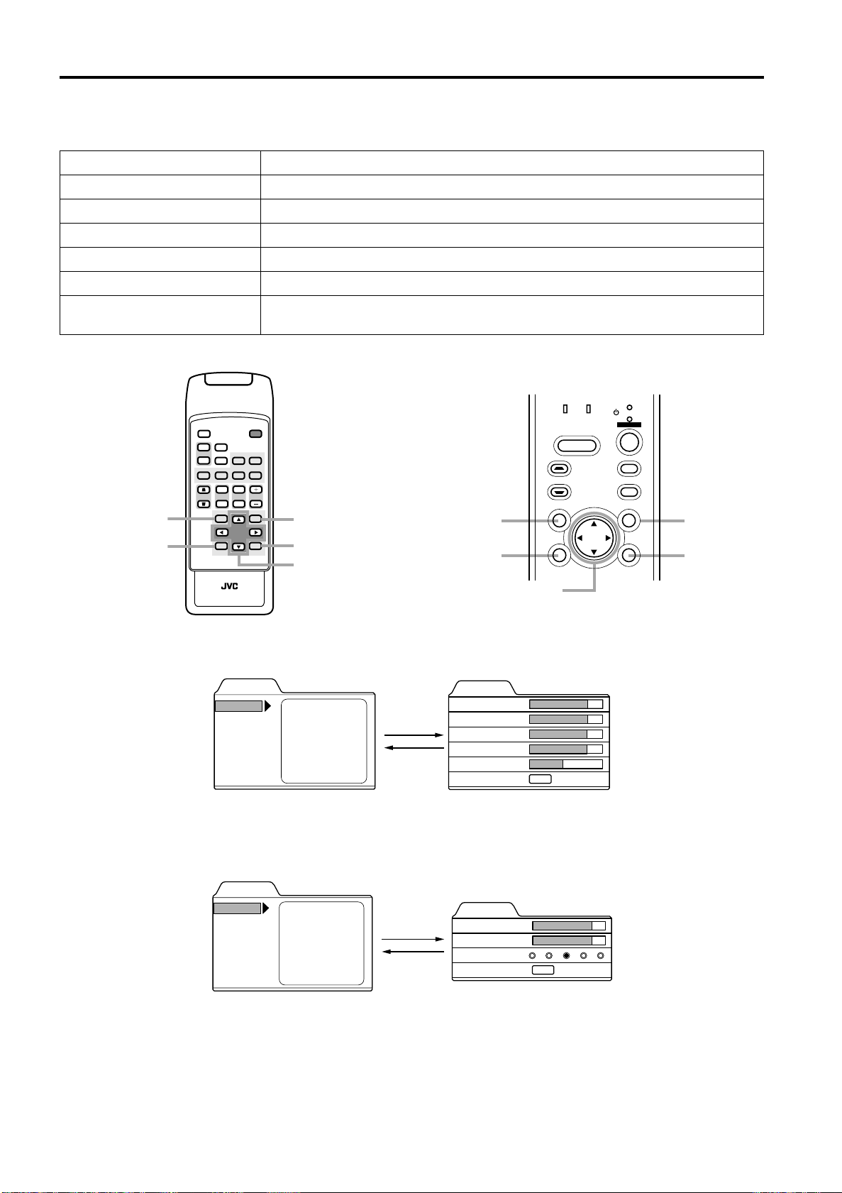
Menu Operations
Basic Menu Operation (Cont.)
Basic Button Functions in the Menu Mode
■
Button Function
MENU Enters the main menu or exits the menu mode.
Cursor button 5/∞ Selects an item in the menu. Pressing ∞ or 5 will scroll the item in the menu.
Cursor button 2/3 Sets or adjusts the value.
PRESET If pressed while the keystone setting submenu is displayed, the value is set to “0”.
EXIT Returns to the previous menu.
ENTER Used to enter the submenu from the main menu.
Used to enter the next submenu if “ENTER” is displayed in the selected item.
■ Remote control unit ■ Projector
QUICK
ALIGN.
W
W
SCREEN
SCREEN
FREEZE
S
S
PC1 PC2
KEYSTONE
PRESET button
PRESET
EXIT button
RM-M160 REMOTE CONTROL UNIT
■ Video menu mode
Press 5/∞ to select an item.
OPERATE
HIDE
COMP
VIDEO
DVI
Y/C
T
T
DIGITAL
ZOOM FOCUS
ZOOM
W
W
MENU
ENTEREXIT
MENU button
ENTER button
Cursor buttons
5/∞ / 2/3
Video main menu
Menu
Image adj.
Set up
Color temp.
Options
Language
Information
Contrast
Brightness
Color
Tint
Sharpness
All reset
3 or
ENTER
EXIT
LAMP TEMP
HIDE
KEYSTONE
PRESET
STAND BY
OPERATE
PC
VIDEO
MENU
PRESET
button
EXIT
button
EXIT ENTER
Cursor buttons
5/∞ / 2/3
Video submenu
Image adj.
Contrast
Brightness
Color
Tint
Sharpness
All reset
12
12
12
12
1
ENTER
Press 5/∞ to select an item.
Press 2/3 to set or adjust the value.
MENU
button
ENTER
button
■ PC menu mode
44
PC main menu
Menu
Image adj.
Set up
Color temp.
Options
Language
Information
Contrast
Brightness
Sharpness
All reset
Press 5/∞ to select an item.
3 or
ENTER
EXIT
PC submenu
Image adj.
Contrast
Brightness
Sharpness
All reset
12
12
1 2 3 4 5
ENTER
Press 5/∞ to select an item.
Press 2/3 to set or adjust the value.
Page 47

Menu Operations
Changing the Color System (Video Menu Mode Only)
This function is available only in Video menu mode.
The menu is only displayed when there is a signal for the AV IN (Y/C, VIDEO and COMP) terminal.
Normally, use the color system in AUTO. If operation in AUTO is unstable, such as color not being shown, set to a dedicated
color system in accordance with the color system of the video signal being input.
Press the MENU button.
1
The main menu appears on the screen.
Select “Set up” with the cursor button 5 or ∞∞∞∞, and press 3333 or the ENTER button.
2
The “Set up 1” submenu appears on the screen.
Select “Decoder” with the cursor button 5 or ∞∞∞∞, and press the ENTER button.
3
The “Decoder” submenu appears on the screen.
Video submenus
Decoder
Set up 1
Position
Gamma
Aspect ratio
Decoder
Page 2
ENTER
Cinema
Down Up
4:3
ENTER
ENTER
16:9
ENTER
EXIT
AUTO [ NTSC ]
NTSC
NTSC4.43
PA L
SECAM
Set the color system with the cursor button 5 or ∞∞∞∞.
4
AUTO: Normally, set to “AUTO”. (Factory set value)
The color system of a video signal being input is automatically identified and displayed in [ ].
In [ ], B/W (Black & White), NTSC, NTSC4.43, PAL or SECAM will be displayed. (It is not always displayed.)
For example, AUTO [ NTSC ] shows that the NTSC signal is being received.
NTSC: Dedicated to NTSC.
NTSC4.43:Dedicated to NTSC4.43.
PAL: Dedicated to PAL.
SECAM: Dedicated to SECAM.
Press the EXIT button to return to the previous menu or press the MENU button to
5
exit the menu mode.
ENGLISHDEUTSHFRANÇAISITALIANOESPAÑOL
45
Page 48

Menu Operations
Changing the Language Display
The on-screen language is set to “English” when shipped from the factory. When you want to change to another language, set
it as follows.
Press the MENU button.
1
The main menu appears on the screen.
Select “Language” with the cursor button 5 or ∞∞∞∞, and press 3333 or the ENTER button.
2
The “Language” submenu appears on the screen.
Language
: Japanese
English
Deutsch
Español
Italiano
Fran çais
Set the language with the cursor button 5 or ∞∞∞∞.
3
English : English
Deutsch : German
Español : Spanish
Italiano : Italian
Français : French
Press the EXIT button to return to the previous menu or press the MENU button to
4
exit the menu mode.
Memo
About language display
Some words in the menu and messages such as “Quick Alignment”, “Keystone”, “VIDEO” and “NTSC” are shown only in
English.
Changing the Screen aspect ratio/HDTV format (Video Menu
Mode Only)
Press the MENU button.
1
The main menu appears on the screen.
Select “Set up” with the cursor button 5 or ∞∞∞∞, and press 3333 or the ENTER button.
2
The “Set up 1” submenu appears on the screen.
Select “Set up 2” with the cursor button 5 or ∞∞∞∞, and press 3333 or the ENTER button.
3
The “Set up 2” submenu appears on the screen.
Select “Screen” or “HDTV” with the cursor button 5 or ∞∞∞∞.
4
Adjust the Screen aspect ratio or HDTV format with the cursor button 2222 or 3333.
5
To adjust multiple items, repeat 4 and 5.
Adjustment item Button Adjustment content
Screen 2 or 3
HDTV 2 or 3
Press the EXIT button to return to the previous menu or press the MENU button to
6
Select according to the aspect ratio of the screen used.
4:3 16:9
Set the number of effective scanning lines. Normally, select 1080i.
1080i: 1035i:
exit the menu mode.
46
Page 49

Menu Operations
Adjusting Tracking/Phase
Normally, tracking and phase adjustments are automatically carried out when a video signal is input to the projector for the
first time, or when the QUICK ALIGN. button on the remote control is pressed.
However, you can manually adjust the tracking and phase on the menu.
If a wide stripe appears on the screen, adjust the lateral size of the picture image and the display area (tracking adjustment)
so the stripe disappears.
Also, if text projected on the screen appears flickers or appears dim, adjust phase adjustment so it becomes clear.
Press the MENU button.
1
The main menu appears on the screen.
Select “Set up” with the cursor button 5 or ∞∞∞∞, and press 3333 or the ENTER button.
2
The “Set up 1” (video mode) or “Set up” submenu appears on the screen.
In video mode: Select set up 2 with the cursor ∞ or 5, and press ENTER button.
The “Set up 2” submenu appears on the screen.
Video submenu PC submenu
Tracking
Phase
Screen
HDTV
Page 1
Set up 2
123
12
ENTER
4:3
1030i
16:9
1035i
Tracking
Phase
Position
Resize
Clamp
Set up
123
12
ENTER
1:1 Panel Aspect
ST BP
Set up 1
Position
Gamma
Aspect ratio
Decoder
Page 2
ENTER
Cinema
Down Up
4:3
ENTER
ENTER
16:9
Decoder is only displayed when there is a signal for the AV
IN terminal.
Select “Tracking” or “Phase” with the cursor button 5 or ∞∞∞∞.
3
Adjust the tracking or phase with the cursor 2222 or 3333.
4
Adjust the tracking and phase of the picture image being projected. To adjust the phase, first check for correct tracking
adjustment.
*To adjust multiple items, repeat 3 and 4.
Adjustment item Button Adjustment content
Tracking 2 or 3
The picture image shrinks laterally (right-to-left) or extends laterally (left-toright). (–128 ↔ +127)
Phase 2 or 3 Set to a position where text appears clear. (0 ↔ 31)
Press the EXIT button to return to the previous menu or press the MENU button to
5
exit the menu mode.
ENGLISHDEUTSHFRANÇAISITALIANOESPAÑOL
Note
• A dim image could be caused by insufficient adjustment of brightness and contrast. Before adjusting phase, make sure that
brightness and contrast are correctly adjusted. To adjust them, refer to “Adjusting Picture Quality” on page 49.
47
Page 50

Menu Operations
Set up for Watching Image Software (Video Menu Mode Only)
This unit has a function which allows you to project movies, which were recorded on film, in the best possible conditions.
(Function to convert 2-3 pull-down interlace scans to progressive scans)
Normally use set to AUTO.
Press the MENU button.
1
The main menu appears on the screen.
Select “Set up” with the cursor button 5 or ∞, and press 3 or the ENTER button.
2
The “Set up 1” submenu appears on the screen.
Select “Set up 2” with the cursor button 5 or ∞, and press 3 or the ENTER button.
3
The “Set up 2” submenu appears on the screen.
Select “Deinterlace” with the cursor button 5 or ∞.
4
Select the Deinterlace function mode with the cursor button 2 or 3.
5
Video: When watching images recorded with a video camera
Film: When watching images recorded on film
AUTO: The setting is changed automatically
Press the EXIT button to return to the previous menu or press the MENU button to
6
exit the menu mode.
Note
• Operates when the signal is an NTSC or PAL interlace signal. Does not operate for other signals. (The menu is not
displayed when other signals are inputted.)
48
Page 51

Menu Operations
Adjusting Picture Quality
In the “Image adj.” submenu, adjust brightness, contrast, sharpness, etc. to obtain the desired picture quality. Note that the
adjustment items differ in Video menu mode and PC menu mode.
Press the MENU button.
1
The main menu appears on the screen.
Select “Image adj.” with the cursor button 5555 or ∞∞∞∞, and press 3333 or the ENTER button.
2
The “Image adj.” submenu appears on the screen.
Video submenu PC submenu
Image adj.
Contrast
Brightness
Color
Tint
Sharpness
All reset
Select the item to be adjusted with the cursor button 5555 or ∞∞∞∞.
3
12
12
12
12
1
ENTER
Image adj.
Contrast
Brightness
Sharpness
All reset
*“Color” and “Tint” are shown in Video submenu only.
Make adjustment with the cursor 2222 or 3333.
4
*To adjust multiple items, repeat 3 and 4.
Adjustment item Button Adjustment content
Contrast 2 or 3 Gets lower/higher. (–30 ↔ 0* ↔ +30)
Brightness 2 or 3 Gets darker/brighter. (–30 ↔ 0* ↔ +30)
Color 2 or 3
Tint 2 or 3
Gets softer/deeper. (–30 ↔ 0* ↔ +30)
(Video menu mode only)
Gets reddish/greenish. (–30 ↔ 0* ↔ +30)
(Video menu mode only)
12
12
1 2 3 4 5
ENTER
ENGLISHDEUTSHFRANÇAISITALIANOESPAÑOL
Gets softer/sharper.
• Video menu mode: (–5 ↔ 0* ↔ +5)
• PC menu mode: (1 ↔ 3* ↔ 5)
Sharpness 2 or 3
All reset ENTER
Note
• When in the PC menu mode, if the resize function in the PC submenu is set to
“1:1”, the image quality will not change even if the value is changed.
Resets above items to the factory set values. How to operate is mentioned below
(next page).
* : Factory set value
■ To perform All Reset
• In the Image adj. submenu, select “All reset” with the cursor button 5 or ∞, and press the ENTER button. Then, the “All
reset” submenu appears on the screen.
• Press the cursor button 2 to select “Yes”, and then press the ENTER button.
• All items in the “Image adj.” submenu are reset to the factory set values and the menu returns to the previous one.
To exit the “All reset” submenu without performing All reset, select “No” with the cursor button 3 and, press the ENTER
button.
(To be continued on the next page)
49
Page 52

Menu Operations
.
Image adj.
All reset?
Ye s
Press the EXIT button to return to the previous menu or press the MENU button to
5
No
exit the menu mode.
Memo
In some adjustments, the level bar changes according to the set value. (The setting value is also displayed at the left of the
level bar.)
Adjusting Color temperature
Press the MENU button.
1
The main menu appears on the screen.
Select “Color temp.” with the cursor button 5555 or ∞∞∞∞, and press 3333 or the ENTER
2
button.
The “Color temp.” submenu appears on the screen.
Select “Color temp.” with the cursor button 5555 or ∞∞∞∞.
3
Adjust the color temperature with the cursor button 2222 or 3333.
4
Low: Color temperature decreases (image becoming reddish).
Middle: Results in middle color temperature. (Factory set position).
High: Color temperature increases (image becoming blueish).
Select “RED” or “GREEN” or “BLUE” with the cursor button 5 or ∞∞∞∞.
5
Fine adjust the color temperature with the cursor button 2222 or 3333.
6
To adjust multiple items, repeat 5 and 6.
Adjustment item Button Adjustment content
RED 2 or 3 Adjusts the red level. (0 to 255)
GREEN 2 or 3 Adjusts the green level. (0 to 255)
BLUE 2 or 3 Adjusts the blue level. (0 to 255)
■ To perform All Reset
• In the Color temp. submenu, select “All reset” with the cursor button 5 or ∞, and press the ENTER button. Then, the “All
reset” submenu appears on the screen.
• Press the cursor button 2 to select “Yes”, and then press the ENTER button.
• All items in the Color temp. submenu are reset to the factory set values and the menu returns to the previous one.
To exit the “All reset” submenu without performing All reset, select “No” with the cursor button 3 and, press the ENTER
button
Press the EXIT button to return to the previous menu or press the MENU button to
7
exit the menu mode.
50
Page 53

Menu Operations
Adjusting the Video Screen/Menu Position
The position of the video screen and the menu on the video screen can be adjusted. You can finely adjust the video screen
position. The menu will move widely on the video screen.
Press the MENU button.
1
The main menu appears on the screen.
Select “Set up” with the cursor button 5555 or ∞∞∞∞, and press 3333 or the ENTER button.
2
The “Set up 1” or “Set up” submenu appears on the screen.
Video submenu (“Set up 1” submenu) PC submenu (Set up submenu)
Tracking
Phase
Position
Resize
Clamp
Set up
123
12
ENTER
1:1 Panel Aspect
ST BP
Set up 1
Position
Gamma
Aspect ratio
Decoder
Page 2
Decoder is only displayed when there is a
signal for the AV IN terminal.
Select “Position” with the cursor button 5555 or ∞∞∞∞, and press the ENTER button.
3
The “Position” submenu appears on the screen.
ENTER
Cinema
Down Up
4:3
ENTER
ENTER
Horizontal position
16:9
Position
Disp.Posi. Menu
12,12
ENTER
Vertical position
ENGLISHDEUTSHFRANÇAISITALIANOESPAÑOL
Press the ENTER button to select “Disp.Posi.” or “Menu”.
4
Disp.Posi. (Display Position):The video screen position (display position) can be adjusted.
Menu:The menu position can be adjusted.
Press the cursor button 5555, ∞∞∞∞, 2222 or 3333 to move the video screen (display) or the
5
menu.
*Repeat 4 and 5 to move both video screen (display) and menu positions.
Adjustment item Button Adjustment content
Disp.Posi. - H 2 or 3 The video screen moves to the left or right. (–30 ↔ +30)
Disp.Posi. - V 5 or ∞ The video screen moves up or down. (–30 ↔ +30)
Menu - H 2 or 3 The menu moves to the left or right. (Left, center*, right)
Menu - V 5 or ∞ The menu moves up or down. (Top, center*, bottom)
* : Factory set value
Press the EXIT button to return to the previous menu or press the MENU button to
6
exit the menu mode.
51
Page 54

Menu Operations
Changing the Image Gamma/Aspect Ratio (Video Menu Mode Only)
The image Gamma (Down, Cinema or Up) and the aspect ratio (4:3 or 16:9) are selectable in Video menu mode.
Press the MENU button.
1
The main menu appears on the screen.
Select “Set up” with the cursor button 5555 or ∞∞∞∞, and press 3333 or the ENTER button.
2
The “Set up 1” submenu appears on the screen.
Video submenu
Set up 1
Position
Gamma
Aspect ratio
Decoder
Page 2
Decoder is only displayed when there is a signal for the Video IN terminal.
ENTER
Cinema
Down Up
4:3
ENTER
ENTER
16:9
Select “Gamma” or “Aspect ratio” with the cursor button 5555 or ∞∞∞∞.
3
Adjust the image tone or aspect ratio with the cursor 2222 or 3333.
4
*To adjust multiple items, repeat 3 and 4.
Adjustment item Button Adjustment content
The image Gamma projected on the screen can be changed.
Gamma 2 or 3
Aspect ratio 2 or 3
* : Factory set value
Press the EXIT button to return to the previous menu or press the MENU button to
5
Down : Suitable for projecting the video programs.
Cinema* : Normally use in this mode.
Up : Suitable for projecting the cinema programs.
Sets the vertical-to-horizontal ratio (4:3 or 16:9) of the video image projected.
“4:3*” : The aspect ratio of the projected image becomes 4:3. Set it to 4:3 for video
of NTSC, NTSC4.43, PAL, SECAM.
“16:9” : The aspect ratio of projected image becomes 16:9. Set it to 16:9 for Hi-
Vision devices (W-VHS VCR, etc.).
exit the menu mode.
52
Page 55

Menu Operations
Changing the Image Size - Resize Function (PC Menu Mode Only)
The picture image projected can be selectable with the
Resize function which is available only in PC menu mode.
You can choose the video image size projected from the
following: (Factory setting is “Aspect”.)
“1:1”: The image is displayed at the input resolution. The
picture image projected is not enlarged even if its
number of pixels (resolution) is smaller than that of
the projector’s D-ILA element (1365 pixels × 1024
pixels).
Resize: 1:1
Full size (1365 × 1024)
Image not enlarged
Panel: The picture image projected is virtually enlarged to
the full size (1365 pixels × 1024 pixels). The
horizontal and vertical enlargement ratio will differ
depending on the original image and the image will
be deformed.
Resize: Panel
Image enlarged
to the full size
(1365 × 1024)
Press the MENU button.
1
The main menu appears on the screen.
Select “Set up” with the cursor button
2
5
5 or ∞∞∞∞, and press 3333 or the ENTER
55
button.
The “Set up” submenu appears on the screen.
PC submenu
Set up
Tracking
Phase
Position
Resize
Clamp
Select “Resize” with the cursor button
3
5
5 or ∞∞∞∞.
55
Choose “1:1”, “Panel”, or “Aspect”
4
123
12
ENTER
1:1 Panel Aspect
ST BP
with the cursor button 2222 or 3333.
Press the EXIT button to return to the
5
previous menu or press the MENU
button to exit the menu mode.
Changing the Clamp pulse position
Image not enlarged
(Original image)
Aspect:While maintaining the original aspect ratio, the video
image projected is virtually enlarged until either the
horizontal or vertical side reaches the full size (1365
pixels × 1024 pixels).
Resize: Aspect
Image enlarged to the aspect size.
(Example: aspect ratio is 16:9)
Full size (1365 × 1024)
Image not enlarged (original image)
(Example: aspect ratio is 16:9)
Image enlarged to the aspect size.
(Example: aspect ratio is 5:4)
Full size (1365 × 1024)
Image not enlarged
(original image)
(Example: aspect ratio is 5:4)
(PC Menu Mode Only)
When the image is too dark or bright, or when the image is
unstable, switching the position may improve the image
quality. Normally, set to “BP”.
Press the MENU button.
1
The main menu appears on the screen.
Select “Set up” with the cursor button
2
5
5 or ∞∞∞∞, and press 3333 or the ENTER
55
button.
The “Set up” submenu appears on the screen.
Select “Clamp” with the cursor button
3
5
5 or ∞∞∞∞.
55
Choose “ST” or “BP” with the cursor
4
button 2222 or 3333.
Press the EXIT button to return to the
5
previous menu or press the MENU
button to exit the menu mode.
ST: Sync Tip BP: Back Porch
ENGLISHDEUTSHFRANÇAISITALIANOESPAÑOL
53
Page 56

Menu Operations
Setting and Adjusting Other Functions (OPTIONS)
Various functions are provided as shown in the “Options 1” and “Options 2” submenus.
You can set or adjust each function, as required.
Press the MENU button.
1
The main menu appears on the screen.
Select “Options” with the cursor button 5555 or ∞∞∞∞, and press 3333 or the ENTER button.
2
The “Options 1” submenu appears on the screen.
Options 1
Menu display
Line display
Lamp time display
Keystone
Lamp control
Page 2
Select the item to be adjusted with the cursor button 5555 or ∞∞∞∞.
3
ENTER
ENTER
ENTER
15sec
5sec
ON
ON
OFF
OFF
Make adjustment with the cursor 2222 or 3333.
4
• While the keystone item is selected, press the ENTER button to display the “Keystone” submenu.
• To enter the “Page 2” submenu, select “Page 2” with the cursor button 5 or ∞, and press the ENTER button.
• To return to the “Page 1” submenu from the “Page 2” submenu, select “Page 1” with the cursor button 5 or ∞, and press
the ENTER button.
Keystone 123
Options
Menu display
Line display
Lamp time display
Keystone
Lamp control
Page 2
ENTER
ENTER
ENTER
15sec
5sec
ON
ON
OFF
OFF
ENTER
ENTER
ENTER
Lamp control
Normal
LPC
LOC
ENTER
ENTER
Page 2
Flip H
Flip V
RS-232C [bps]
Sleep time [min]
Page 1
OFF
OFF
9600
15 30 60 OFF
ENTER
ON
ON
19200
*To adjust multiple items, repeat 3 to 4.
*To reset the keystone (trapezoidal distortion of the picture image) to the original setting, press the PRESET button when
the “Keystone” submenu appears on the screen.
54
Page 57

Adjustment item Button Adjustment content
Sets whether to clear the menu display automatically or not.
Menu display 2 or 3
Line display 2 or 3
Lamp time display 2 or 3
Keystone ENTER
Lamp control ENTER
Flip H 2 or 3
Flip V 2 or 3
RS-232C [bps] 2 or 3
15sec* : Clears the display automatically in about 15 seconds.
ON : Does not automatically clear the menu display.
Sets whether to show the line display (Y/C, VIDEO, COMP, PC1, PC2 or DVI) on top
right of the screen or not when the VIDEO or PC button is pressed.
5sec* : Shows the line display for about 5 seconds.
OFF : Does not show the line display.
Displays the lamp use time.
ON* : Displays when the lamp use time reaches 1000 hours when set in the LPC or
LOC mode.
OFF : Does not display when the lamp use time reaches 1000 hours when set in the
LPC or LOC mode.3
Press the ENTER button to enter the keystone submenu.
In the keystone submenu, press 2 or 3 to correct trapezoidal distortion of the
projected image. (–80 ↔ 0* ↔ +128)
To reset the keystone (trapezoidal distortion of the picture image) to the original
setting (factory set value: 0), press the PRESET button when the “Keystone”
submenu appears on the screen.
To exit the keystone submenu, press the EXIT button.
Press ENTER to enter the lamp control submenu.
Normal*
LPC : Automatically controls the power used by the lamp and increases it in
LOC : The brightness can be set in seven levels (-6 to 0). Since the brightness
Reverses image right-to-left.
OFF* : For the front method.
ON : For upside-down hanging from the ceiling.
Inverses image upside-down.
OFF* : For normal setup.
ON : For upside-down hanging from the ceiling.
Sets the baud rate for transmission.
9600 : 9600 bps
19200* : 19200 bps
: Used as a normal lamp.
steps. When this mode is used, the brightness starts at approximately
70%. The decrease in brightness is slower than in “Normal” mode and this
mode is best suited when using the projector continuously for long periods
of time.
* “Lamp replacement” appears on the screen when the lamp use time
exceeds 2000 hours.
can be set in steps, this is the mode best suited for adjusting multiple
screens. This setting can also be changed while the projector is being
used. To change the setting, choose LOC with the 5/∞ cursors and
choose the level with the 2/3 cursors.
Menu Operations
ENGLISHDEUTSHFRANÇAISITALIANOESPAÑOL
Sleep time [min] 2 or 3
* Factory set value
Press the EXIT button to return to the previous menu or press the MENU button to
5
Sets the length of sleep time which automatically brings the projector into stand-by
state. You can select one of the sleep times: 15, 30, 60 and 0 (OFF*) minutes.
exit the menu mode.
Note
• Refer to “Removing the Trapezoidal Distortion of the Image” on page 35 for more details about adjusting the keystone.
55
Page 58

Menu Operations
Getting Information
You can get information on the input signal, accumulated used hours of light-source lamp, etc.
Press the MENU button.
1
The main menu appears on the screen.
Select “Information” with the cursor button 5555 or ∞∞∞∞.
2
The “Information” will be displayed in the main menu.
*No submenu can be selected.
Video main menu PC main menu
Menu
Image adj.
Setting
Color temp.
Options
Language
Information
Input
Switcher
Source
Lamp time
VIDEO
CH.0
NTSC
123 h
Menu
Image adj.
Setting
Color temp.
Options
Language
Information
Input
Switcher
Resolution
Frequency H
Frequency V
Lamp time
PC 1
CH.0
1280 1024
kHz
79.9
Hz
75
h
123
Input: Shows the terminal name selected by the VIDEO or PC button. (Y/C, VIDEO or COMP, or PC1, PC2 or DVI)
Switcher: This display currently has no meaning. This is reserved for future use. (“CH.0” is usually displayed to
indicate that it is not being used.)
Source: Shows the projected image’s type of video signal. (Video menu mode)
Resolution: Shows the resolution of the video signal being received. (PC menu mode)
It may not be displayed correctly with some input signals.
Frequency H: Shows the horizontal frequency of the video signal being received. (PC menu mode)
Frequency V: Shows the vertical frequency of the video signal being received. (PC menu mode)
Lamp time: Accumulated used hours of the light-source lamp.
Press the MENU button to exit the menu mode.
3
56
Page 59

Replacing the Fuse
A fuse is used to protect the power source of the projector. If the fuse is blown, replace it. When the power switch is turned on
but no power is supplied to the projector, check the fuse. If there are any unclear points, contact the dealer where you
purchased your projector, or consult the Service center.
CAUTION
• When replacing the fuse, use the same rating and type (T6.3A H 250 V). Otherwise, a fire may occur and/or the projector
may be damaged.
Turn off the main power switch and
1
R
E
T
N
E
U
N
E
O
M
E
D
I
V
C
E
P
P
A
C
S
E
E
T
A
R
E
P
O
T
E
S
E
E
R
P
N
O
T
E
S
D
I
Y
P
E
H
M
K
E
T
P
M
A
disconnect the power cord from both
the projector and the wall outlet.
In stand-by state (the STAND BY indicator lights on),
place the MAIN POWER switch of OFF [ ] position.
Loosen the fuse holder to remove it.
2
To loosen the fuse holder, use a Flat-end screwdriver.
L
N
W
DO
P
U
Remove the fuse from the fuse holder
3
you just removed.
Install the new fuse (not supplied) into
4
the fuse holder.
Reinstall the fuse holder into the
5
projector.
To reinstall the fuse holder, use a Flat-end screwdriver.
Fuse holder
Flat-end screwdriver
Fuse (T6.3A H 250 V)
Fuse holder
ENGLISHDEUTSHFRANÇAISITALIANOESPAÑOL
Fuse (T6.3A H 250 V)
Fuse holder
57
Page 60

Replacing the Light-Source Lamp
■ Light-source lamp and lamp use time
The light-source lamp has a service life of approximately 1000 hours.
[Average lamp life: 1000 hours (brightness half-life)]
When the light-source lamp approaches the end of its service life, degradation progresses rapidly. In NORMAL MODE,
arrange for a new lamp (lamp unit) or replace the lamp after 900 hours. Depending on the usage conditions, the replacement
time may be shorter.
(In LOC and LPC modes, the brightness of the lamp is electrically controlled and the replacement time is extended. Arrange
for a new lamp (lamp unit) or replace the lamp after 1900 hours. Depending on the usage conditions, the replacement time
may be shorter.)
If, even after adjusting the brightness or color, the video image is dark or the color is not correct, replace the lamp early.
The lamp use time can be checked. Look at the “Lamp time” which is displayed with the “Information” option in the menu.
(Refer to page 40, 42.)
Contact the store from where you purchased the projector or the JVC service center for details about purchasing
replacement lamps.
Replacement lamp (lamp unit) part number: BHL 5001-SU
The LAMP indicator and the message on the screen warn you that replacement of the lamp is required, as follows:
■ Projecting after the lamp has been used for more than 900 hours (NORMAL MODE)
Accumulated used hours
of the light-source lamp
When the lamp use time reaches 900 hours:
900 hours
1000 hours
1010 hours
The LAMP indicator lights on the projector.
When starting to project after 900 hours has been exceeded:
“Lamp replacement” appears on the screen.
* The message will disappear when any button is pressed.
When the lamp use time exceeds 1000 hours:
The LAMP indicator blinks on the projector.
“Lamp replacement” appears on the screen and the word “Warning”
blinks.
* To cancel this message, press the EXIT button.
However, the same message will appear every hour.
* If the projector is put in stand-by mode or turned off after the lamp has
been used for more than 1000 hours (but less than 2010 hours), it can
not be turned back on again unless the light-source lamp is replaced
with a new one.
Replace with a new lamp (lamp unit) and reset the lamp time. (Refer
to page 62.)
When the lamp use time reaches 1010 hours:
The projector is forcibly turned off.
The LAMP and OPERATE indicators blinks on the projector.
* The projector can not be turned on unless the lamp (lamp unit) is
replaced with a new one and the lamp time is reset. (Refer to
page 62.)
Lamp replacement
EXIT
Warning
Lamp replacement
EXIT
Note
• If the projector is not put in stand-by mode or turned off, it can be used until 2010 hours is reached.
58
Page 61

Replacing the Light-Source Lamp
■ Projecting after the lamp has been used for more than 1000 hours (LIGHT OUTPUT
CONTROL MODE) (LAMP POWER CONTROL MODE)
Accumulated used hours
of the light-source lamp
When the lamp use time reaches 1000 hours:
1000 hours
1900 hours
2000 hours
2010 hours
“1000h” and “Lamp replacement” appear on the screen.
* The messages will disappear when any button is pressed.
* The time after which the display appears can be set with the OSD
menu.
When the lamp use time exceeds 1900 hours:
The LAMP indicator blinks on the projector.
“Lamp replacement” appears on the screen.
* To cancel this message, press the EXIT button or display another
menu.
Every time the projector is turned on, the message appears.
When the lamp use time exceeds 2000 hours:
The LAMP indicator blinks on the projector.
“Lamp replacement” appears on the screen and the word “Warning”
blinks.
* To cancel this message, press the EXIT button.
However, the same message will appear every hour.
* If the projector is put in stand-by mode or turned off after the lamp has
been used for more than 2000 hours, it can not be turned back on
again unless the light-source lamp is replaced with a new one.
(If the projector is not put in stand-by mode or turned off, it can be
used until 2010 hours is reached.)
Replace with a new lamp (lamp unit) and reset the lamp time. (Refer
to page 62.)
When the lamp use time reaches 2010 hours:
The projector is forcibly turned off.
The LAMP and OPERATE indicators blinks on the projector.
* The projector can not be turned on unless the lamp (lamp unit) is
replaced with a new one and the lamp time is reset. (Refer to
page 62.)
1000 h
Lamp replacement
EXIT
Lamp replacement
EXIT
Warning
Lamp replacement
EXIT
CAUTIONS
• If the projector is set up in a constricted place which is unsuitable for work, and if you perform replacement work there, this
could cause injury. Move the projector to a place large enough for work, and then replace the light-source lamp.
• Use a genuine product for the light-source lamp. If you use other than a genuine product, this could cause a malfunction.
Also, never use an old light-source lamp. This could cause marked degradation in performance or explode, possibly causing
the projector to malfunction or broken pieces to injure you.
• Do not replace the light-source lamp immediately after the projector has been used. The temperature of the light-source
lamp is still high and could cause a burn. Allow a cooling period of one hour or more before performing replacement.
• Before starting light-source lamp replacement work, turn off the MAIN POWER switch, and disconnect the power cord from
the wall outlet. If you perform the replacement work with the power cord connected, this could cause injury or electric shock.
• The light-source lamp used in this projector is a high pressure mercury lamp. Be careful when disposing of the light-source
lamp. If anything is unclear, please consult your dealer.
ENGLISHDEUTSHFRANÇAISITALIANOESPAÑOL
59
Page 62

Replacing the Light-Source Lamp
t
■ Be sure that the power cord is unplugged from the wall outlet.
Remove the lamp-replacement opening
1
cover by loosening screws.
Loosen the two screws with a flat-end screwdriver.
Note
• The screws are fitted so that they do not come off the lamp-
replacement opening cover.
Screw
Lamp-replacemen
opening cover
Loosen the screws, raise the handle,
2
and pull out the light-source lamp.
Loosen the two screws with a flat-end screwdriver.
Note
• The screws are fitted so that they do not come off the light-
source lamp.
Be careful not to damage
the claw.
Screw
Light-source lamp
60
Handle
(To be continued on the next page)
Page 63
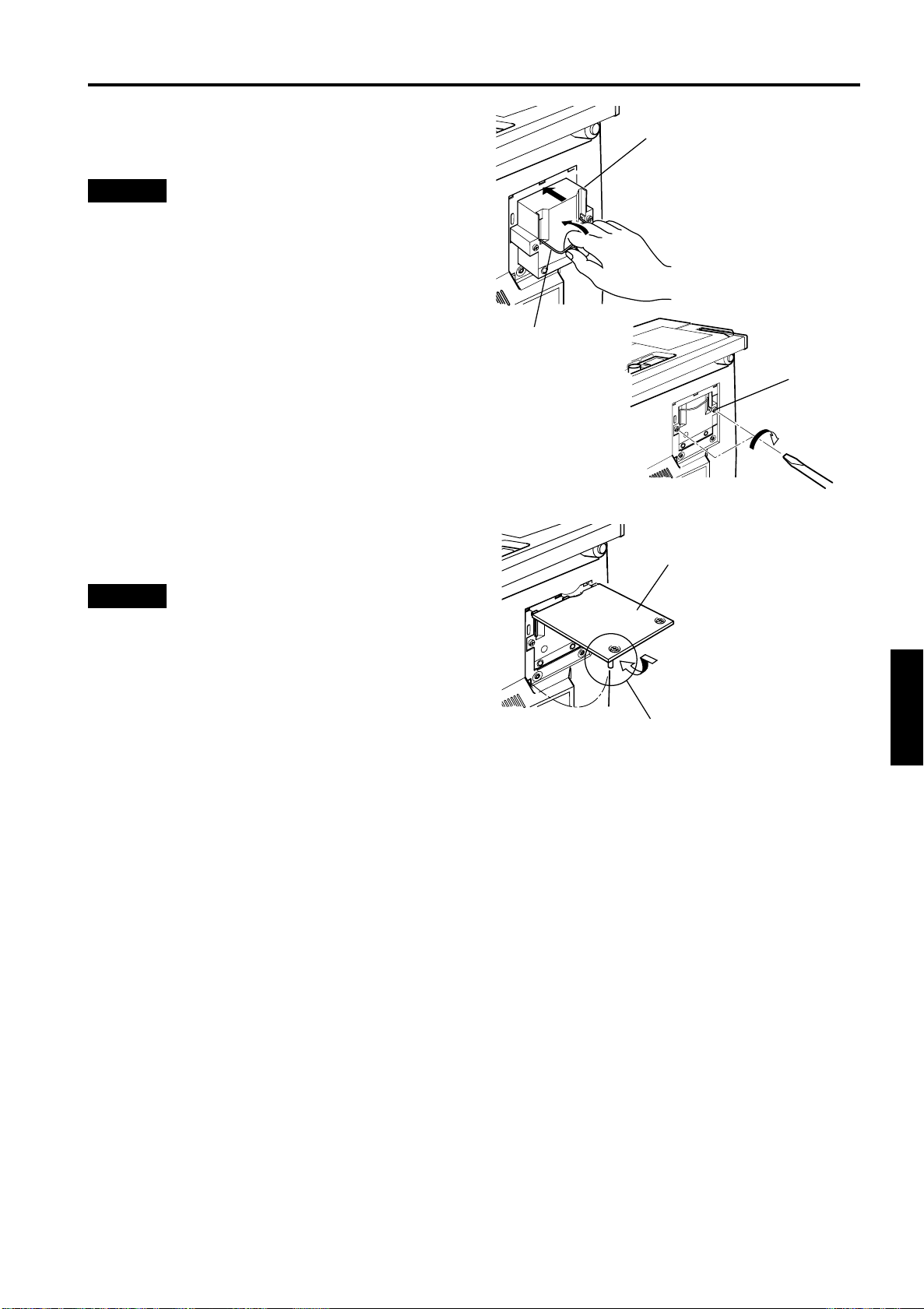
Insert the new light-source lamp fully
3
inside and fasten the screws.
Fasten the two screws with a flat-end screwdriver.
CAUTION
• Do not touch the glass surface of the light-source lamp
directly with your hand as well as staining it. If you touch
with a bare hand, oils and other substances on your hand
may adhere to the lamp, possibly preventing it from
performing as specified and therefore giving a shortened
lamp life, a darkened screen, etc. To handle a new lightsource lamp, hold it by the plastic part. Never touch the
metal part or the front glass surface.
Replacing the Light-Source Lamp
Light-source lamp
Handle
Screw
Replace the lamp-replacement opening
4
cover and fasten the screws.
Fasten the two screws with a flat-end screwdriver.
CAUTIONS
• Install the light-source lamp and close the lampreplacement opening cover correctly; otherwise, a safety
switch is activated to prevent the projector from operating.
• If the claw on the lamp-replacement opening cover is
damaged, the projector may not possibly operate. Then,
replace with a new lamp-replacement opening cover.
Reset the lamp use time.
5
Perform “Resetting the Lamp Use Time” on page 62.
Lamp-replacement
opening cover
Be careful not to
damage the claw.
ENGLISHDEUTSHFRANÇAISITALIANOESPAÑOL
61
Page 64

Replacing the Light-Source Lamp
■ Resetting the Lamp Use Time
After replacing with a new light-source lamp, reset the lamp-time counter inside the projector to clear the accumulated lamp
time to zero (0). After resetting, a new count will start for the new light-source lamp.
Turn on the MAIN POWER switch to go
■ Projector’s button
1
into stand-by mode.
In stand-by mode, the STAND BY indicator on the
projector lights up.
Press the following buttons on the
2
projector, sequentially.
1 Momentary press the PC button.
2 Momentary press the ENTER button.
3 Momentary press the EXIT button.
4 Press and hold the HIDE button for two seconds
or more.
* During this sequence, the STAND BY and OPERATE
indicators alternately blink about every approx. 3 seconds.
After completion of the sequence, the STAND BY indicator
alone stays on.
* Buttons must be pressed within 2 seconds of the previous
button.
* When you make a mistake in button operations, return to
the beginning of the sequence.
* To check the lamp time on the menu, press the MENU button
and select “Information” with the cursor button 5 or ∞.
The lamp use time is indicated in the item “Lamp time”.
4
HIDE
button
3
EXIT
button
LAMP TEMP
HIDE
KEYSTONE
PRESET
EXIT ENTER
STAND BY
OPERATE
PC
VIDEO
MENU
Cursor buttons 5/∞
STAND BY
indicator
OPERATE
indicator
1
PC
button
MENU
button
2
ENTER
button
Video main menu
Menu
Image adj.
Setting
Color temp.
Options
Language
Information
Input
Switcher
Source
Lamp time
VIDEO
CH.0
NTSC
123 h
Lamp time (0 h)
PC main menu
Menu
Image adj.
Setting
Color temp.
Options
Language
Information
Input
Switcher
Resolution
Frequency H
Frequency V
Lamp time
PC 1
CH.0
1280 1024
kHz
79.9
Hz
75
h
123
Lamp time (0 h)
CAUTION
• Reset the lamp use time only when you have replaced with
a new light-source lamp. Never reset it during lamp life,
otherwise the replacement time may become unclear, and
lead to degraded performance or lamp explosion.
62
Page 65

Cleaning and Replacing the Filter Cover
Clean the filter regularly. If the filter is heavily stained and does not clean, or if it is damaged, replace the filter with a new filter.
Otherwise, dirt may get inside and appear on the screen, preventing you from fully enjoying the video image. If dirt gets inside
or if you need information about the filter, consult authorized dealer where you purchased the projector or the nearest Service
Center.
Turn off the MAIN POWER switch.
1
After the projector goes into stand-by state with the STAND BY indicator on, turn off the MAIN POWER switch and pull
out the power cord from the projector and the wall outlet.
Remove the filter.
2
Loosen the screw with a flat-end screwdriver.
Screw
Filter
Be careful not to
damage the claws.
Notes
• The screw is fitted so that it does not come off the filter.
• If the filter is clogged with dirt, etc., the projector goes into an warning state (the OPERATE and STAND BY indicator blink.
etc.). Therefore regularly, clean the filter. For the warning indication, refer to page 67.
Clean the filter.
3
Clean the filter with a neutral detergent, wash it in water, and then dry it in the shade.
CAUTIONS
• Put on rubber gloves when using neutral detergent.
• After you have washed the filter in water, make sure the filter is completely dry before reinstalling it, otherwise an electric
shock or malfunction could occur.
• Do not clean the filter using a vacuum cleaner. Since the filter is soft, it may be sucked into the vacuum cleaner or damaged.
ENGLISHDEUTSHFRANÇAISITALIANOESPAÑOL
Reinstall the filter.
4
Fasten the screw with a flat-end screwdriver.
Notes
• Install the filter correctly. Otherwise, the projector does not operate. (Goes into an warning state (For the warning indication,
Refer to page 66).)
• If the filter’s claws (in particular the claw which is hidden behind the filter cover knob) are damaged, the projector may not
operate. Then, replace with a new filter.
63
Page 66

Troubleshooting
Solutions to common problems related to your projector are described here. If none of the solutions presented here solves the
problem, unplug the projector and consult an authorized dealer or Service Center.
Symptom Probable cause Corrective action Page
Power is not
supplied.
Light is not emitted,
or light level is low.
With power on,
operation starts but
stops in a few
minutes.
Video image does not
appear.
Video image dims. • Is focus adjusted correctly? • Adjust focus. 12, 34
Video image is
abnormally dark or
bright.
Video image freezes. • Was the FREEZE button on the
• Is the power cord disconnected? • Insert the power cord (plug) firmly. 30
• Is the MAIN POWER switch turned
on?
• Is the fuse blown? • Turn off the MAIN POWER switch and
• Is the lamp-replacement opening cover
closed correctly?
• Is the filter closed correctly? • Turn off the MAIN POWER switch, fit the
• Has the lamp life expired? (Has the
lamp use time reached 1000 hours in
the normal mode?)
(Has the lamp use time reached 2000
hours in the LPC or LOC mode?)
• Is the lens cap removed? • Remove the lens cap. 30
• Is the lamp life near its end? • Check the lamp use time on the menu, and
• Is the air intake or exhaust area
blocked?
• Is the correct input selected? • Select the correct input with the VIDEO and
• Are devices connected correctly? • Connect devices correctly. 11, 22
• Are signals being supplied from the
connected devices?
• Are input signals (scanning frequency,
etc.) appropriate?
• Is the correct color system selected? • Set the color system to AUTO or to the
• Is brightness adjusted correctly? • Adjust brightness on the menu. 49
• Is video turned off by pressing the
HIDE button?
• During DVI input, are image signals
output from the computer graphic
board (DVI output terminal)?
(During DVI input, depending on the
computer settings, there may be no
signal input or an error may occur (blue
screen).)
• Is distance too short or too long? • Set the projector at the correct distance. 18, 76,
• Are Tracking and Phase adjusted
correctly?
• Is picture quality (Brightness, etc.)
adjusted correctly?
remote control pressed?
• Turn on the MAIN POWER switch. 32
57
check the fuse.
If it is blown, replace it
• Turn off the MAIN POWER switch, close
the lamp-replacement opening cover
correctly, and turn on the MAIN POWER
switch again.
filter correctly, and turn on the MAIN
POWER switch again.
• Turn off the MAIN POWER switch, replace
with a new light-source lamp, and turn on
the MAIN POWER switch.
Reset the lamp use time after replacing with
a new lamp.
if the lamp life is near its end, arrange for a
replacement lamp, or replace a little earlier.
• Turn off the MAIN POWER switch, remove
any blocking objects, and turn on the MAIN
POWER switch again.
PC buttons.
• Set connected devices correctly. –
• Check if the signal is appropriate (scanning
frequency, etc.) and input the appropriate
signal.
correct dedicated color system.
• Press the HIDE button to turn video on. 10, 12,
• If this happens, turn off the power to both
the projector and the computer, and then
turn the projector back on before turning the
computer on again. Then correctly set the
computer’s graphic board.
• If satisfactory results are not obtained by
pressing the QUICK ALIGN. button to
conduct quick alignment, adjust Tracking
and Phase on the menu.
• Adjust picture quality on the menu. 49
• Press the FREEZE button to release
freezing.
7, 32, 60
7, 32, 63
32, 58,
59, 62
56, 58,
59
6, 7, 32
9, 13
22, 23
45
35
22
77
13, 36,
47
12, 37
64
Page 67

Troubleshooting
Symptom Probable cause Corrective action Page
A part of image is
magnified.
Color is poor or
unstable.
The upper part of the
video image bows or
distorts.
Video image
suddenly go out.
Remote control unit
does not work.
* This device uses a computer. External noise may cause it to malfunction. If this happens, turn the power off, remove the
electric plug from the wall outlet. Then insert the electric plug back into the wall outlet, turn the power back on and check the
operation.
• Was the DIGITAL ZOOM T button on
the remote control pressed?
• Is picture quality (color density, etc.)
adjusted correctly?
• Is the correct color system selected? • Set the color system to AUTO or to the
• Are signals (scanning frequency, etc.)
of the connected devices appropriate?
• While computer system signal is input,
isn’t a sync signal for composite sync
(Cs) or G on sync being input?
• Isn’t signal with much jitter or skew
distortion being input from a video
deck?
• Is video picture turned off by pressing
the HIDE button?
• Are batteries installed correctly? • Match the polarities of batteries correctly (+
• Are batteries exhausted? • Replace with new batteries. 14
• Is there a shielding object between the
remote control unit and the remote
sensor?
• Is the distance too long? • Use the remote control unit at a nearer
• Is either side of remote cable
disconnected?
• Press the PRESET button to restore the
original video screen.
• Adjust picture quality on the menu. 49
correct dedicated color system.
• Check if the signal is appropriate (scanning
frequency, etc.), and input the appropriate
signal.
• Input separate sync signals for vertical sync
(V) and horizontal sync (H) signals.
• Input signals with little jitter or distortion.
Use a TBC or a device with a built-in TBC.
• Turn on video picture by pressing the HIDE
button.
to + and – to –).
• Remove any shielding objects. 20
point.
• Firmly insert the remote cable when using
the remote control unit as the wired one.
12, 37
45
22
11, 28
10, 12,
35
14
20
21
–
■ When warning indication is shown by the blinking indicators:
The warning status will be notified by the combination lighting of the projector’s indicators.
For the warning contents and the action to be taken, refer to “Warning Indication” on page 66.
Maintenance
■
• Stains on the cabinet
These should be wiped off with a soft cloth. If the cabinet is heavily stained, wipe it with a cloth soaked in water-diluted
neutral detergent and wring well, then wipe clean with a dry cloth.
• Since the cabinet may deteriorate in quality, become damaged, or show paint peeled, note the following:
– Do not wipe with rough cloth.
– Do not wipe vigorously.
– Do not wipe with thinner or benzene.
– Do not apply any volatile substance such as insecticides.
– Do not allow any rubber or vinyl article to remain in contact with the cabinet for a long time.
• Stains on the lens
These should be cleaned off with commercially available lens blowers or lens cleaning paper (for cleaning glasses and
cameras).
Do not use liquid cleaning agents. This could cause the surface coating to be removed.
Do not rub, scratch or hit the lens as its surface is prone to damage.
ENGLISHDEUTSHFRANÇAISITALIANOESPAÑOL
65
Page 68

Warning Indication
If something abnormal has occurred with the projector, the warning status will be indicated by the combination of lighting the
indicators on the control panel as shown in the following table. Then, the projector automatically stops projection and runs the
cooling fan for about 120 seconds.
Warning indication table:
No.
1 Blink Blink The light-source lamp does not light and projection
2 Blink Blink The light-source lamp has suddenly gone off during
3 Blink Blink Circuit operation is abnormal.
4 Blink Blink The filter is displaced.
5 Blink The internal temperature is too high. (Sensor 1)
6 Blink Blink The internal temperature is too high. (Sensor 2)
7 Blink Blink Blink Blink The cooling fan has stopped (locked).
* For individual indicator lighting, refer to page 58.
Action to be taken for warning indication
■
LAMP TEMP STAND BY OPERATE
Indicator
Warning content
is not made.
projecting an image.
Stopping the projector:
After the cooling fan has stopped, take the following action.
No. 1 : Check that the cover for replacing the light-source lamp and the front panel are securely attached, and then, press
the OPERATE button for one second or more to turn on the projector for retrying.
No. 2 : Check that the cover for replacing the light-source lamp and the front panel are securely attached, and then, press
the OPERATE button for one second or more to turn on the projector for retrying.
No. 3 : Press the OPERATE button for one second or more to turn on the projector for retrying.
Nos. 4-7 : Follow the next steps.
1. Turn off the MAIN POWER switch and unplug the power cord from the wall outlet.
2. Take an action according to the number.
No. 4 : Set the filter in place.Then, leave the projector until it cools down.
No. 5 : Check that nothing is blocking the air inlet nor outlet, and wait until the inside cools down.
No. 6 : Check that nothing is blocking the air inlet nor outlet, and wait until the inside cools down.
No. 7 : Leave the projector until it cools down.
3. Plug in the power cord again, turn on the MAIN POWER switch, and press the OPERATE button for one second or
more to turn on the projector for retrying.
Retrying operation:
Plug in the power cord again and operate the projector.
If the same warning indication is observed again, after the cooling fan has stopped, turn off the MAIN POWER switch, unplug
the power cord, and call your dealer for repair.
66
Page 69

Warning Messages
The following shows the warning messages that can be displayed on the screen. When a warning message is displayed, take
the corrective action described here.
Message Cause Corrective action Page
PC 1
No Input
• No device is connected to the
input terminal.
• The terminal is connected but no
signal is output from the
connected device.
* The selected input mode (input
terminal) name is shown in the
first line of the massage.
• Connect a device to the selected
terminal.
• Operate the connected device
and output a signal.
9, 11,
24 ~ 29,
33
PC 1
Frequency of input signal is out of range.
PC 1
Signal is not supported.
FREEZE
• The frequency of the input video
signal is out of range.
• The selected input mode (input
terminal) name is shown in the
first line of the message.
• Though the frequency of the input
video signal is within the
acceptable range, other items
such as resolution are out of the
projector’s specifications.
• The selected input mode (input
terminal) name is shown in the
first line of the message.
• When the FREEZE button is
pressed, this message appears
for a few seconds.
• When a button not acceptable is
pressed during freezing, this
message appears for a few
seconds to notify that the image is
being frozen.
• Input the video signals whose
frequency is within the projector’s
specifications.
• Input the video signals that
satisfies the projector’s
specifications.
• To release freezing, press the
FREEZE button on the remote
control.
22, 23,
70
22, 23,
70
12, 37
ENGLISHDEUTSHFRANÇAISITALIANOESPAÑOL
FREEZE
• When the FREEZE button is
pressed for the video signals that
cannot be frozen (UXGA 60Hz,
SXGA 60Hz.), this message
appears for a few seconds to
notify that the image cannot be
frozen.
* To forcibly clear the message,
press the EXIT button.
• Freeze function does not work for
the inputted video signals.
To use this function, input the
video signals that can be frozen.
12, 37
67
Page 70

Warning Messages
Message Cause Corrective action Page
D.ZOOM
• When the DIGITAL ZOOM button
is pressed for the video signals
that cannot be zoomed (UXGA
60Hz, SXGA 60Hz.), this
message appears for a few
seconds to notify that the image
cannot be digitally zoomed.
* To forcibly clear the message,
press the EXIT button.
• Digital-zoom function does not
work for the inputted video
signals.
To use the this function, input the
video signals that can be digitally
zoomed.
13, 37
Lamp replacement
EXIT
Warning
Lamp replacement
EXIT
Displayed when the lamp control
setting is set to NORMAL MODE
• Appears every time the projector
is turned on after the lamp use
time has exceeded 900 hours and
until it reaches 1000 hours.
* The message is cleared by
pressing any button.
Displayed when the lamp control
setting is set to NORMAL MODE
• When the lamp use time reaches
1000 hours, the word “Warning”
blinks on the screen.
* To cancel this message, press
the EXIT button.
However, the same message will
appear every hour.
* If the power is turned off after the
lamp use time has exceeded
1000 hours, the power can not be
turned on again.
* When the lamp use time reaches
1010 hours, the projector is
forcibly turned off and can not be
turned back on again.
• Arrange for a new lamp (lamp
unit) or replace the lamp early.
• Replace with a new lamp (lamp
unit) and reset the lamp time.
44, 46
44, 46
68
Page 71

Warning Messages
Message Cause Corrective action Page
• Arrange for a new lamp (lamp
unit) or replace the lamp early.
• Arrange for a new lamp (lamp
unit) or replace the lamp early.
1000 h
Lamp replacement
EXIT
Lamp replacement
EXIT
Displayed when the lamp control
setting is set to LIGHT OUTPUT
CONTROL MODE (LOC) or LIGHT
POWER CONTROL MODE (LPC)
and the lamp use time display is
turned [ON] with the OSD menu
• Displayed when the lamp use
time exceeds 1000 hours.
* The message does not appear if
the lamp use time display is
turned [OFF] with the OSD menu.
Displayed when the lamp control
setting is set to LIGHT OUTPUT
CONTROL MODE (LOC) or LIGHT
POWER CONTROL MODE (LPC)
• Appears every time the projector
is turned on after the lamp use
time has exceeded 1900 hours
and until it reaches 2000 hours.
* The message is cleared by
pressing any button.
44, 46
44, 46
Displayed when the lamp control
setting is set to LIGHT OUTPUT
• Replace with a new lamp (lamp
unit) and reset the lamp use time.
44, 46
CONTROL MODE (LOC) or LIGHT
POWER CONTROL MODE (LPC)
Warning
Lamp replacement
EXIT
• When the lamp use time reaches
2000 hours, the word “Warning”
blinks on the screen.
* To cancel this message, press
the EXIT button.
However, the same message will
appear every hour.
* If the power is turned off after the
lamp use time has exceeded
2000 hours, the power can not be
turned on again.
* When the lamp use time reaches
2010 hours, the projector is
forcibly turned off and can not be
turned back on again.
Memo
The message display language corresponds to the menu display language setting. This is set to “English (English)” when the
projector is bought. The display language can be selected from 6 languages. (Refer to page 46.) However, the input mode
(PC1, PC2, DVI, Y/C, VIDEO, COMP) and button indications (FREEZE, D.ZOOM, EXIT) are only displayed in English
irrespective of the display language setting.
The language settings in the section are explained in “English”.
ENGLISHDEUTSHFRANÇAISITALIANOESPAÑOL
69
Page 72

Specifications
Optical mechanism system
■
• Projection method D-ILA® (Direct Drive Image Light Amplifier) method
®
• D-ILA
• Projecting lens GL-M2910G: 1:1
• Screen size GL-M2910G: Refer to page 76.
• Projection distance GL-M2910G: Refer to page 76.
• Light-source lamp 420 W xenon lamp
■
• Color system NTSC, NTSC4.43, PAL, SECAM (Automatic switching / manual switching)
• Resolution 1365 dots × 1024 dots (S-XGA full resolution, during RGB input)
• Scanning frequency Horizontal frequency : 15 kHz ~ 105 kHz
• Audio power output 1 W (monaural), 4 cm round type micro-speaker × 1
device
Electrical system
(Reflective-type active-matrix method)
2.3 cm measured diagonally (1365 pixels × 1024 pixels) × 3
(Total number of pixels : 4,193,280)
GL-M2915SG: 1.5:1 (with ±2% zooming/shift function)
GL-M2920ZG: × 1.5 zoom lens (2:1 to 3:1) (zooming function)
GL-M2930SZG: × 1.9 zoom lens (2.9 to 5.5:1) (zooming/shift function)
GL-M2915SG: Refer to page 76.
GL-M2920ZG: Refer to page 77.
GL-M2930SZG: Refer to page 77.
GL-M2915SG: Refer to page 76.
GL-M2920ZG: Refer to page 77.
GL-M2930SZG: Refer to page 77.
1000 TV lines (Horizontal resolution, aspect ratio 4 : 3, during video input)
Vertical frequency : 50 Hz ~ 100 Hz
Input terminals
■
[AV IN]
• Y/C 1-line, mini-DIN 4 pin × 1 (for S-video)
• VIDEO 1-line, BNC × 1 (for composite video)
1-line, BNC × 3 (for computer, DTV or video)
• Y, B-Y, R-Y Component (Y, B-Y, R-Y) signal
, P
B
• Y, P
[PC 1]
• R, G, B, H, V 1-line, D-sub 3-row 15 pin × 1 (for computer)
[PC 2]
• R, B, G Analog RGB signal
• H/C
[DVI] 1-line, DVI-D 24-pin × 1
[CONTROL]
• RS-232C 1-line, D-sub 9-pin × 1
• REMOTE 1-line, stereo mini-jack × 1
R
, V Horizontal (H) sync/composite (CS) sync, Vertical (V) sync signal
s
DTV-format (Y, PB, PR) signal
1-line, BNC × 5 (for computer, DTV or video)
* RS-232C-interface specified control terminal for controlling this projector with a personal
computer.
* Remote terminal for connecting with the remote control unit.
Output terminal
■
• PC OUT 1-line, D-sub 3-row 15-pin × 1 (output for display monitor)
• CONTROL OUT 1-line, D-sub 9-pin × 1
* RS-232C-interface specified control terminal for controlling this projector with a personal
computer.
70
Page 73

Specifications
General
■
• Power requirements 200 V - 240 V AC, 50/60 Hz
• Power consumption 4 A
• Allowable operation
temperature
• Allowable relative
humidity
• Allowable storage
temperature
• Dimensions Approx. 505 mm × 265 mm × 393 mm
• Weight Approx. 14.6 kg
• Accessories (Refer to page 5.)
* Design and specifications are subject to change without notice.
* D-ILA devices are manufactured with a very high-precision technology, allowing 99.99% of the pixels to be effective. Only
0.01% or less of the pixels are missing or always on.
* For easy understanding, pictures and illustrations maybe emphasized, composed or have omissions and may be more or
less different from actual products.
* TRADEMARKS
D-ILA is a trademark of Victor Company of Japan, Limited.
IBM and IBM PC are registered trademarks of International Business Machines Corporation. Macintosh is a registered
trademarks of Apple Computer, Inc.
VESA is a trademark of the non-profit organization Video Electronics Standards Association.
All other product names mentioned herein are used for identification purposes only, and may be the trademarks or
registered trademarks of their respective companies.
+ 5°C to + 35°C
20% to 80% (no condensation)
– 10°C to + 60°C
[Carrying band, Excluding protrusions]
(Width × Height × Depth)
ENGLISHDEUTSHFRANÇAISITALIANOESPAÑOL
71
Page 74

Specifications
Outside dimensions
■ Top
*1
505
EXIT ENTER
MENU
PRESET
VIDEO
KEYSTONE
PC
HIDE
OPERATE
LAMP TEMP
STAND BY
*2
369
393
133
■ Front ■ Side
*1
505
393
Unit: mm
*1: Protrusion excluded
*2: Lens excluded
*2
52
392
212
53
265
70
265
256
72
Page 75

Pin assignment (Specifications for terminals)
■ Y/C terminal
Pin number Signal name
34
1GND (Y)
2GND (C)
Specifications
2
1
■ RS-232C terminal
6
7189
5
2
3
4
■ PC1 terminal/PC OUT terminal
11
121314
15
3Y
4C
Pin number Signal name Pin number Signal name
1N/C6N/C
2RD7N/C
3 TD8N/C
4N/C9N/C
5GND
Pin number Signal name Pin number Signal name
1Red9N/C
2 Green 10 GND (SYNC)
7
6
3
1
8910
2
■ DVI terminal
9111315
10 12 14 16
12345678
17
18192021222324
3 Blue 11 GND
4N/C12N/C
5N/C13H.SYNC
5
4
Pin
number
1 T.M.D.S.Data2- 9 T.M.D.S.Data1- 17 T.M.D.S.Data0-
2 T.M.D.S.Data2+ 10 T.M.D.S.Data1+ 18 T.M.D.S.Data0+
3
4 No Connect 12 No Connect 20 No Connect
5 No Connect 13 No Connect 21 No Connect
6 DDC Clock 14 +5V Power 22 T.M.D.S. Clock
7 DDC Data 15 Ground (for +5 V) 23 T.M.D.S. Clock +
8 No Connect 16 Hot Plug Detect 24 T.M.D.S. Clock -
T.M.D.S.Data2
Shield
6 GND (Red) 14 V.SYNC
7 GND (Green) 15 N/C
8 GND (Blue)
Signal name
Pin
number
11
Signal name
T.M.D.S.Data1
Shield
Pin
number
19 T.M.D.S.Data0
Signal name
Shield
Shield
ENGLISHDEUTSHFRANÇAISITALIANOESPAÑOL
73
Page 76

RS-232C external control
By connecting a computer to the RS-232C terminal, you can control the projector. Use a reverse connection cable as the RS232C connection cable.
The commands to control the projector and the response data against the received commands are explained here.
For further information, please consult the dealer where you purchased your projector or consult the Service Center.
1. Communication Specifications
The communication specifications are as follows:
Baud rate 9600bps / 19200bps*
Data length 8 bits
Parity None
Stop bit 1 bit
Flow control None
* Factory set value. To change the value, refer to “Setting and Adjusting Other Functions (OPTIONS)” on page 54.
2. Command Format
2-1. Command data format (from the computer to the projector)
When sending a control command, use the following data format.
Header ID SP Command SP Parameter CR
Header: Designates the head of data and the kind of data.
“!” (21h): Control command to the projector
“?” (3Fh): Query to the projector (Asking command)
ID: “1” (fixed)
SP: Designates the delimiter for ID, Command, and Parameter. (20h)
CR: Designates the terminal of the data. (0Dh)
* [ ] is not necessary when Asking command.
2-2. Response data format (from the projector to the computer)
Upon executing the received control command, the projector sends back the following response data to the computer.
Header ID SP Normal Termination Status SP Parameter CR
Header: Designates the head of data.
“@” (40h): Fetches data from the projector.
ID: “1” (fixed)
SP: Designates the delimiter for ID, Command, and Parameter (20h)
Normal Termination Status: “0” (30h)
CR: Designates the terminal of the data (0Dh)
74
Page 77

2-3 Parameters used for the data format
The following three kinds of parameters are prepared for the control command and response data.
(1) Numeric value
Designates the 2-byte hexadecimal value with the sign as the 4-digit (byte) characters.
Designation allowable range: “8000” to “7FFF”
(2) ON/OFF
Designates the status (ON/OFF) of the projector, such as POWER and HIDE.
Character Hex. Meaning
“0” 30 OFF
“1” 31 ON
(3) Special parameters
Input switching parameters:
Character Hex. Meaning
“0” 30 Y/C
“1” 31 VIDEO
“2” 32 COMP
“3” 33 PC1
RS-232C external control
“4” 34 PC2
“5” 35 DVI
Operation mode parameters:
Character Hex. Meaning
“0000” 30h, 30h, 30h, 30h Stand-by mode
“0001” 30h, 30h, 30h, 31h Power-on mode
“0002” 30h, 30h, 30h, 32h Cool-down mode
“0004” 30h, 30h, 30h, 34h Warning mode
3. Control command table
The control commands that can be sent from the computer are as follows:
Function Command
OPERATE U0F –– – ✓ –
HIDE U00 ✓ –– ✓ –
Right Left rev. U17 ✓ –– ✓ –
Top Bottom inv. U18 ✓ –– ✓ –
Keystone U40 ✓ – ✓ ––
Input U1A
Asking Kind of data
Power ON ELSE Numeric Value ON/OFF Special Data
✓ –– –
Y/C, VIDEO, PC1, PC2,
COMP, DVI
ENGLISHDEUTSHFRANÇAISITALIANOESPAÑOL
Operation mode Z03
* Keystone: Numeric value can range from “FF80” to “0080”
* Operation mode: Only Asking command is possible
✓✓ ––
Stand-by, Power-on,
Cool-down, Warning
75
Page 78

Appendix
■ Relationship between Projection Distances and Projection Screen Sizes
Notes
• The relationship between the projection distances and projection screen sizes differs depending on the lens unit (optional)
you are using.
• The projection distance and projection screen sizes listed here are only for a guide. Use them as reference when setting the
projector.
For lens unit GL-M2910G (1:1):
Projection screen size
(Diagonal length)
36.7" (approx. 93.2 cm) --- 2.53 (0.77)
40" (approx. 101.6 cm) 2.53 (0.77) 2.76 (0.84)
50" (approx. 127.0 cm) 3.18 (0.97) 3.48 (1.06)
60" (approx. 152.4 cm) 3.84 (1.17) 4.20 (1.28)
70" (approx. 177.8 cm) 4.53 (1.38) 4.95 (1.51)
80" (approx. 203.2 cm) 5.18 (1.58) 5.68 (1.73)
90" (approx. 228.6 cm) 5.87 (1.79) 6.40 (1.95)
100" (approx. 254.0 cm) 6.53 (1.99) 7.12 (2.17)
110" (approx. 279.4 cm) 7.22 (2.20) 7.87 (2.40)
120" (approx. 304.8 cm) 7.87 (2.40) 8.60 (2.62)
130" (approx. 330.2 cm) 8.53 (2.60) 9.32 (2.84)
140" (approx. 355.6 cm) 9.22 (2.81) 10.04 (3.06)
150" (approx. 381.0 cm) 9.88 (3.01) 10.79 (3.29)
160" (approx. 406.4 cm) 10.56 (3.22) 11.52 (3.51)
170" (approx. 431.8 cm) 11.22 (3.42) 12.24 (3.73)
180" (approx. 457.2 cm) 11.88 (3.62) 12.96 (3.95)
190" (approx. 482.6 cm) 12.57 (3.83) 13.68 (4.17)
200" (approx. 508.0 cm) 13.22 (4.03) ---
For lens unit GL-M2915SG (1.5:1):
Projection screen size
(Diagonal length)
55" (approx. 139.7 cm) --- 6.00 (1.83)
60" (approx. 152.4 cm) 5.77 (1.76) 6.30 (1.92)
65" (approx. 165.1 cm) 6.27 (1.91) 6.82 (2.08)
70" (approx. 177.8 cm) 6.76 (2.06) 7.38 (2.25)
75" (approx. 190.5 cm) 7.28 (2.22) 7.91 (2.41)
80" (approx. 203.2 cm) 7.78 (2.37) 8.46 (2.58)
85" (approx. 215.9 cm) 8.27 (2.52) 9.02 (2.75)
90" (approx. 228.6 cm) 8.76 (2.67) 9.55 (2.91)
95" (approx. 241.3 cm) 9.28 (2.83) 10.10 (3.08)
100" (approx. 254.0 cm) 9.78 (2.98) 10.63 (3.24)
105" (approx. 266.7 cm) 10.27 (3.13) 11.19 (3.41)
110" (approx. 279.4 cm) 10.76 (3.28) 11.75 (3.58)
115" (approx. 292.1 cm) 11.25 (3.43) 12.27 (3.74)
120" (approx. 304.8 cm) 11.78 (3.59) 12.83 (3.91)
125" (approx. 317.5 cm) 12.27 (3.74) 13.35 (4.07)
130" (approx. 330.2 cm) 12.76 (3.89) 13.91 (4.24)
135" (approx. 342.9 cm) 13.25 (4.04) 14.44 (4.40)
140" (approx. 355.6 cm) 13.75 (4.19) --145" (approx. 368.3 cm) 14.27 (4.35) --150" (approx. 381.0 cm) 14.76 (4.50) ---
Approximate projection distance unit: ft (m)
For 4:3 aspect-ratio screens For 16:9 aspect-ration screens
Approximate projection distance unit: ft (m)
For 4:3 aspect-ratio screens For 16:9 aspect-ration screens
76
Page 79

For lens unit GL-M2920ZG (2 to 3:1):
Projection screen size
(Diagonal length)
40" (approx. 101.6 cm) --------- --------- --------- 8.53 (2.60)
42" (approx. 106.7 cm) --------- 8.23 (2.51) --------- 9.96 (2.73)
50" (approx. 127.0 cm) --------- 9.74 (2.97) --------- 10.60 (3.23)
60" (approx. 152.4 cm) --------- 11.65 (3.55) 8.50 (2.59) 12.66 (3.86)
70" (approx. 177.8 cm) 9.09 (2.77) 13.55 (4.13) 9.84 (3.00) 14.73 (4.49)
80" (approx. 203.2 cm) 10.33 (3.15) 15.42 (4.70) 11.22 (3.42) 16.80 (5.12)
100" (approx. 254.0 cm) 12.83 (3.91) 19.23 (5.86) 13.94 (4.25) 20.90 (6.37)
150" (approx. 381.0 cm) 19.09 (5.82) 28.71 (8.75) 20.77 (6.33) 31.23 (9.52)
200" (approx. 508.0 cm) 25.33 (7.72) 38.16 (11.63) 27.59 (8.41) 41.54 (12.66)
240" (approx. 609.6 cm) 30.35 (9.25) 45.73 (13.94) 33.04 (10.07) 49.80 (15.18)
250" (approx. 635.0 cm) 31.59 (9.63) 47.64 (14.52) 34.38 (10.48) 51.87 (15.81)
300" (approx. 762.0 cm) 37.86 (11.54) 57.09 (17.40) 41.21 (12.56) 62.17 (18.95)
310" (approx. 787.4 cm) 39.11 (11.92) 58.99 (17.98) 42.59 (12.98) 64.24 (19.58)
320" (approx. 812.8 cm) 40.35 (12.30) 60.89 (18.56) 43.93 (13.39) --------330" (approx. 838.2 cm) 41.60 (12.68) 62.76 (19.13) 45.31 (13.81) --------340" (approx. 863.6 cm) 42.85 (13.06) 64.67 (19.71) 46.65 (14.22) --------350" (approx. 889.0 cm) 44.09 (13.44) --------- 48.03 (14.64) ---------
400" (approx. 1016.0 cm) 50.36 (15.35) --------- 54.86 (16.72) --------450" (approx. 1143.0 cm) 56.63 (17.26) --------- 61.65 (18.79) --------470" (approx. 1193.8 cm) 59.12 (18.02) --------- 64.37 (19.62) --------480" (approx. 1219.2 cm) 60.37 (18.40) --------- --------- --------500" (approx. 1270.0 cm) 62.89 (19.17) --------- --------- --------521" (approx. 1323.3 cm) 65.52 (19.97) --------- --------- ---------
Appendix
Approximate projection distance unit: ft (m)
For 4:3 aspect-ratio screens For 16:9 aspect-ration screens
Wide end Tele end Wide end Tele end
For lens unit GL-M2930SZG (2.9 to 5.5:1):
Projection screen size
(Diagonal length)
Wide end Tele end Wide end Tele end
40" (approx. 101.6 cm) --------- 14.83 (4.52) --------- 16.11 (4.91)
50" (approx. 127.0 cm) --------- 18.44 (5.62) --------- 20.05 (6.11)
60" (approx. 152.4 cm) --------- 22.05 (6.72) --------- 23.98 (7.31)
70" (approx. 177.8 cm) --------- 25.66 (7.82) 14.83 (4.52) 27.92 (8.51)
80" (approx. 203.2 cm) 15.55 (4.74) 29.30 (8.93) 16.93 (5.16) 31.86 (9.71)
100" (approx. 254.0 cm) 19.36 (5.90) 36.52 (11.13) 21.06 (6.42) 39.76 (12.12)
150" (approx. 381.0 cm) 28.87 (8.80) 54.59 (16.64) 31.43 (9.58) 59.45 (18.12)
200" (approx. 508.0 cm) 38.39 (11.70) 72.67 (22.15) 41.77 (12.73) 79.17 (24.13)
240" (approx. 609.6 cm) 45.96 (14.01) 87.14 (26.56) 50.07 (15.26) 94.91 (28.93)
250" (approx. 635.0 cm) 47.86 (14.59) 90.78 (27.67) 52.13 (15.89) --------260" (approx. 660.4 cm) 49.77 (15.17) 94.39 (28.77) 54.20 (16.52) --------270" (approx. 685.8 cm) 51.67 (15.75) 97.99 (29.87) 56.27 (17.15) --------280" (approx. 711.2 cm) 53.58 (16.33) --------- 58.33 (17.78) --------300" (approx. 762.0 cm) 57.38 (17.49) --------- 62.50 (19.05) --------350" (approx. 889.0 cm) 66.90 (20.39) --------- 72.83 (22.20) ---------
400" (approx. 1016.0 cm) 76.41 (23.29) --------- 83.20 (25.36) --------470" (approx. 1193.8 cm) 89.70 (27.34) --------- 97.70 (29.78) --------480" (approx. 1219.2 cm) 91.60 (27.92) --------- --------- --------500" (approx. 1270.0 cm) 95.41 (29.08) --------- --------- --------510" (approx. 1295.4 cm) 97.31 (29.66) --------- --------- ---------
Approximate projection distance unit: ft(m)
For 4:3 aspect-ratio screens For 16:9 aspect-ration screens
ENGLISHDEUTSHFRANÇAISITALIANOESPAÑOL
77
Page 80

78
Page 81

Wir danken Ihnen für den Kauf dieses Projektors. Bevor Sie ihn benutzen alle Anweisungen lesen und ihnen
sorgfältig folgen, um die Möglichkeiten dieses Projektors voll auszunutzen.
SICHERHEITSMASSNAHMEN
WICHTIGE INFORMATIONEN
WARNUNG :
UM FEUER ODER STROMSSCHLAGGEFAHREN
ZU VERHINDERN, DAS GERÄT WEDER REGEN
NOCH EINER ANDEREN FLÜSSIGKEIT
AUSSETZEN.
WARNUNG :
DIESES GERÄT MUSS GEERDET SEIN.
VORSICHT :
Um das Stromschlagrisiko zu senken, die
Abdeckung nicht entfernen.
Kundendienstarbeiten durch qualifiziertes
Wartungspersonal durchführen lassen.
MASCHINENLÄRMINFORMATION
(Nur Deutschland)
Änderungen zur 3. GSGV.
Maschinenlärminformationsverordnung, 18.
Januar 1991: Der Schalldruck.pegel an der
Bedienerstellung beträgt 70 dB(A) oder weniger
gemäß ISO 7779.
Einbrenngefahr bei D-ILA-Gerät
Nicht zulassen, daß ein bestimmtes Standbild für längere
Zeit oder ein fehlerbedingt helles Bild projiziert wird.
Videobilder mit hoher Lichtstärke oder hohem Kontrast nicht
auf eine Projektionswand werfen. Das Videobild könnte in
das D-ILA-Gerät eingebrannt werden.
Besondere Sorgfalt walten lassen, wenn Videospiele oder
Computerprogramm-Bilder projiziert werden. Es sind keine
Probleme beim Abspielen von herkömmlichen
Videokassetten-Bildern bekannt.
Über den Aufstellungsort
Stellen Sie den Projektor nicht an Orten auf, die das Gewicht
des Projektors nicht tragen können.
Wenn der Aufstellungsort keine ausreichende Tragfähigkeit
aufweist, könnte der Projektor herunterfallen oder umkippen
und auf diese Weise Personen verletzen.
WICHTIGE
SICHERHEITSMASSNAHMEN
Elektrische Energie kann zu vielen nützlichen Zwecken
eingesetzt werden. Dieses Gerät ist im Hinblick auf Ihre
persönliche Sicherheit konstruiert und hergestellt worden. Aber
EINE UNSACHGEMÄSSE VERWENDUNG DES GERÄTS
LAMM EOMEM BRAMD ODER STROMSCHLAG
AUSLÖSEN. Um die in diesem Gerät eingebauten
Schutzvorrichtungen nicht zu umgehen, müssen die folgenden
Grundregeln für Installation, Gebrauch und Wartung
eingehalten werden. Bitte lesen Sie die folgenden “Wichtige
Sicherheitsmaßnahmen” vor Gebrauch sorgfältig durch.
– Alle Sicherheits- und Bedienanweisungen müssen vor
der Inbetriebnahme des Produkts gelesen werden.
– Die Sicherheits- und Bedienungsanleitung zur späteren
Bezugnahme aufbewahren.
– Alle Warnungen auf dem Gerät und in der
Bedienungsanleitung beachten.
– Alle Bedienungsanweisungen unbedingt befolgen.
– Den Projektor in der Nähe einer Steckdose aufstellen, wo
der Netzstecker leicht abgezogen werden kann.
– Vor der Reinigung immer das Gerät vom Netz trennen.
Keine Flüssigkeit- oder Aerosolreinigungsmittel
verwenden. Zur Reinigung ein feuchtes Tuch verwenden.
– Keine Geräteerweiterungen benutzen, die nicht vom
Gerätehersteller empfohlen werden, da sie gefährlich
sein können.
– Das Gerät nicht in der Nähe von Wasser benutzen. Das
Gerät nicht sofort benutzen, wenn es von einem kalten in
einen warmen Raum gebracht wird, da dies
Kondensation verursacht, die wiederum zu Brand,
Stromschlag und anderen Gefahren führen kann.
– Das Gerät nicht auf einen instabilen Rollwagen, Ständer
oder Tisch stellen. Es kann um- bzw. Herunterfallen,
wobei Kinder oder auch Erwachsene schwer verletzt
werden können oder das Gerät schwer beschädigt
werden kann. Das Gerät nach den Anweisungen des
Herstellers aufstellen und eine Halterung benutzen, die
vom Hersteller empfohlen wird.
– Wenn das Gerät auf einem Rollwagen benutzt wird,
müssen abrupte Stopps, übermäßige
Kraftanwendung und Unebenheiten, die das
Gerät und den Rollwagen zum Umkippen
bringen können, vermieden werden,
wodurch das Gerät beschädigt oder der
Bediener verletzt werden kann.
– Schlitze und Öffnungen im Gehäuse sind für die Lüftung
vorhanden. Sie sichern den zuverlässigen Betrieb des
Geräts und schützen es vor Überhitzung. Diese
Öffnungen dürfen nicht blockiert oder abgedeckt werden.
(Die Öffnungen dürfen nie blockiert werden, indem das
Gerät auf ein Bett, Sofa, einen Teppich oder eine ähnlich
geartete Fläche gestellt wird. Es darf nicht in eine
eingebaute Konstruktion wie ein Bücherregal oder einen
Rahmen gestellt werden,sofern nicht für die richtige
Lüftung gesorgt wird und die Anweisungen des
Herstellers eingehalten werden.)
Für die richtige Lüftung das Gerät von anderen Geräten
getrennt halten, die die Lüftung beeinträchtigen können
und einen Abstand von mehr als 60 cm beibehalten.
ENGLISHDEUTSCHFRANÇAISITALIANOESPAÑOL
1
Page 82

– Dieses Gerät darf nur mit der Art von Stromquelle
betrieben werden, die auf dem Typenschild angegeben
ist. Wenn Sie sich nicht über die Art der Stromversorgung
in Ihrem Hause sicher sind, fragen Sie Ihren Fachhändler
oder Ihr örtliches Stromversorgungsunternehmen.
– Dieses Gerät ist mit einem dreipoligen Stecker
ausgerüstet. Dieser Stecker paßt nur in eine geerdete
Netzsteckdose. Wenn Sie nicht in der Lage sind, den
Stecker in die Steckdose einzustecken, setzen Sie sich
mit Ihrem Elektriker in Verbindung, um die richtige
Steckdose zu installieren. Nicht die Sicherheitsfunktion
des geerdeten Steckers umgehen.
– Netzkabel müssen so verlegt werden, daß niemand auf
sie treten oder sie durch darauf liegende oder dagegen
gelehnte Gegenstände anderweitig beschädigt werden
können. An Türen, Steckern, Steckdosen und an der
Stelle, an der die Kabel das Gerät verlassen, besonders
acht geben.
– Den Netzstecker von der Wandsteckdose zum
zusätzlichen Schutz dieses Geräts während eines
Gewitters, oder wenn es für längere Zeit nicht benutzt
oder unbeaufsichtigt stehen gelassen wird, abziehen und
das Kabelsystem abtrennen. Dadurch wird ein möglicher
Schaden am Gerät durch Blitzschlag oder NetzleitungsSpannungsstöße verhindert.
– Wandsteckdosen, Verlängerungskabel oder Zusatz-
Steckdosen an anderen Geräten nicht überlasten, da
dies eine Brand- und Stromschlaggefahr darstellen kann.
– Nie Gegenstände welcher Art auch immer durch die
Öffnungen in dieses Gerät stecken, da sie gefährliche
Spannungspunkte berühren können, was einen Brand
oder elektrischen Schlag auslösen kann. Keine
Flüssigkeiten auf dem Gerät verschütten.
– Nicht versuchen, dieses Gerät selbst zu warten, da Sie
durch Öffnen oder Entfernen der Abdeckungen
gefährlichen Spannungen und anderen Gefahren
ausgesetzt werden können. Alle Kundendienstarbeiten
qualifiziertem Wartungspersonal überlassen.
– Unter den folgenden Umständen den Stecker aus der
Wandsteckdose herausziehen und
Kundendienstarbeiten von qualifiziertem
Wartungspersonal ausführen lassen:
a) Wenn das Netzkabel oder der Netzstecker
beschädigt ist.
b) Wenn Flüssigkeit auf dem Gerät verschüttet wurde
oder Gegenstände in das Gerät geraten sind.
c) Wenn das Gerät Regen oder Wasser ausgesetzt
worden ist.
d) Wenn das Gerät bei Befolgung der
Bedienungsanleitung nicht normal funktioniert. Nur
die Bedienelemente einstellen, die von der
Bedienungsanleitung behandelt werden, da eine
falsche Einstellung von Bedienelementen zu
Schäden führen kann und oft umfassende
Korrekturarbeiten von einem qualifizierten Techniker
erforderlich machen, um das Gerät wieder in
Normalbetrieb zurückzuführen.
e) Wenn das Gerät fallengelassen oder auf andere
Weise beschädigt worden ist.
f ) Wenn das Gerät eine deutliche Veränderung in seiner
Leistung zeigt, zeigt das einen Wartungsbedarf an.
– Wenn Ersatzteile erforderlich sind, sicherstellen, daß der
Servicetechniker Ersatzteile benutzt, die durch den
Hersteller empfohlen werden oder die gleichen
Eigenschaften wie die ursprünglichen Teile haben. Nicht
vom Hersteller zugelassene Ersatzteile können einen
Brand, Stromschlag oder andere Gefahren auslösen.
– Nach Beendigung aller Kundendienstarbeiten oder
Reparaturen an diesem Gerät den Servicetechniker
bitten, die Sicherheitsüberprüfungen auszuführen, um
den einwandfreien Betriebszustand des Gerätes
sicherzustellen.
– Das Gerät mehr als 35 cm von Wärmequellen wie
Heizkörpern, Wärmespeichern, Öfen und anderen
Geräten (einschließlich Verstärkern) aufstellen, die
Wärme erzeugen können.
– Wenn Sie andere Geräte wie Videorekorder oder
Personalcomputer einschalten, müssen Sie die
Stromversorgung dieses Geräts zum Schutz gegen
elektrischen Schlag ausschalten.
– Brennbares Material nicht hinter den Kühlungslüfter
aufbewahren. Zum Beispiel Tücher, Papier,
Streichhölzer, Aerosoldosen oder Gasanzünder, die bei
Überhitzung besondere Gefahrenherde darstellen.
– Nicht in die Projektionslinse blicken, während die
Projektionslampe eingeschaltet ist. Ein direkter Blick in
das extrem grelle Licht kann die Sehkraft dauerhaft
beeinträchtigen.
– Nicht durch die Öffnungen (Lüftungsöffnungen) usw. in
das Innere des Geräts blicken. Nicht durch Öffnen des
Schranks direkt in die Projektionslampe blicken, wenn
die Projektionslampe eingeschaltet ist. Die
Projektionslampe produziert auch UV-Strahlen, und die
Leuchtkraft ist so stark, daß Augenschäden
hervorgerufen werden können.
– Die Projektionslampe (Lampeneinheit) nicht fallenlassen,
gegen Gegenstände anschlagen oder auf irgendeine
Weise beschädigen. Dabei kann die Lampe bersten, was
zu Verletzungen führen kann. Keine beschädigte
Projektionslampe verwenden. Falls die Projektionslampe
beschädigt ist, lassen Sie das Gerät beim Fachhändler
reparieren. Fragmente von einer geborstenen
Projektionslampe können Verletzungen verursachen.
– Xenongas ist mit Hochdruck in der Projektionslampe
(Lampeneinheit) dieses Projektors eingeschlossen. Wenn
Sie die Lampe fallen lassen, einem Stoß aussetzen oder
einfach so entsorgen, kann sie explodieren, was zu
Personenschäden führen kann. Daher die Lampe mit
größter Vorsicht handhaben. Wenn Sie weitere
Unterstützung benötigen, wenden Sie sich an Ihren
Fachhändler.
– Montieren Sie den Projektor nicht an einem Ort an der
Decke, der Schwingungen ausgesetzt ist. Andernfalls
kann die Halterung des Projektors durch die
Schwingungen beschädigt werden, so daß der Projektor
herunterfallen oder umkippen und auf diese Weise zu
Verletzungen führen kann.
– Nur Zubehörkabel benutzen, die für dieses Gerät
ausgelegt sind, um Stromschlag zu vermeiden.
Die Netzspannung dieses Geräts ist 200 - 240 V
Wechselstrom, das angeschlossene Netzkabel entspricht
der folgenden Speisespannung. Nur das Netzkabel
benutzen, das von unserem Händler zur Sicherstellung
von Sicherheit und EMV vorgesehen ist.
Wenn das Gerät mit einer anderen Speisespannung
benutzt wird, muß das Netzkabel gewechselt werden.
Stellen Sie sicher, daß das für den Projektor verwendete
Netzkabel das für die an Ihrem Wohnort vorhandenen
Steckdosen geeignete ist.
Lassen Sie sich von Ihrem Fachhändler beraten.
Netzkabel
Für Vereinigtes Königreich
Für kontinentaleuropäische
Länder
* Lassen Sie das Gerät NICHT von
unqualifiziertem Personal installieren.
Bitten Sie unbedingt Ihren Fachhändler, das Gerät zu
installieren (d.h. an der Decke anzubringen), da zur
Installation spezielle technische Kenntnisse und
Fähigkeiten erforderlich sind.
Wenn die Installation von unqualifiziertem Personal
vorgenommen wird, besteht die Gefahr von
Verletzungen oder elektrischen Schlägen.
2
Page 83

NETZANSCHLUSS
(Nur Vereinigtes Königreich)
WARNUNG
Nicht den Netzstecker von diesem Gerät abtrennen.
Wenn der mitgelieferte Stecker nicht für die vorhandene
Steckdose geeignet ist, besorgen Sie ein geeignetes,
sicherheitsgeprüftes Verlängerunskabel oder einen Adapter
oder lassen Sie sich von Ihrem Fachhändler beraten.
Wenn trotzdem der Netzstecker abgetrennt wird, die
Sicherung entfernen und den Stecker sofort entsorgen, um
eine mögliche Stromschlaggefahr durch ungewollte
Verbindung zur Netzversorgung zu vermeiden.
Wird ein neuer Netzstecker angebracht, der Anleitung unten
folgen.
WARNUNG:
DIESES GERÄT MUSS GEERDET SEIN.
WICHTIG:
Die Drähte im Netzkabel an diesem Gerät sind wie folgt
farbkodiert:
Grün-und-Gelb: Erde
Blau: Neutral
Braun: Stromführend
Der grün/gelbe Draht muß mit der Klemme verbunden
werden, die mit dem Buchstaben E oder dem
Erdungssymbol gekennzeichnet oder verbunden ist.
Der blaue Draht muß mit der Klemme verbunden werden,
die mit dem Buchstaben N gekennzeichnet oder schwarz ist.
Der braune Draht muß mit der Klemme verbunden werden,
die mit dem Buchstaben L gekennzeichnet oder rot ist.
Beim Ersetzen einer Sicherung sicherstellen, daß nur eine
zugelassene Sicherung der richtigen Stärke verwendet wird,
und den Sicherungsdeckel wieder einsetzen.
WENN ZWEIFEL ——WENDEN SIE SICH AN EINEN
BESTEHEN QUALIFIZIERTEN ELEKTRIKER.
Wie die Sicherung ersetzt wird
Das Fach für die Sicherung mit einem
Schlitzschaubendreher öffnen und die Sicherung ersetzen.
(* Siehe hierzu die nachfolgende Abbildung)
Da diese Farben nicht unbedingt der Farbcodierung Ihrer
Steckdose entpsrechen, folgendermaßen verfahren:
Sicherung
ENGLISHDEUTSCHFRANÇAISITALIANOESPAÑOL
3
Page 84

Inhalt
SICHERHEITSMASSNAHMEN ........ 1
Inhalt................................................. 4
Zubehörteile..................................... 5
Bedienungselemente und
Merkmale.......................................... 6
Vorderseite / Oberseite / Rechte Seite....................6
Linke Seite / Rückseite............................................7
Unterseite................................................................8
Bedienfeld am Projektor..........................................9
Anschlußfeld .........................................................11
Fernbedienungsteil................................................12
Einsetzen der Batterien.........................................14
Vorsichtsmaßnahmen für die Verwendung von
Batterien................................................................14
Installieren des Projektors............ 15
Vorsichtsmaßnahmen für die Installation ..............15
Einstellung der Neigung des Projektors................16
Installieren des Projektors gegen die
Projektionswand....................................................17
Projektionsabstand und Projektionswandgröße
Einstellung des Grades der
Objektivverschiebung............................................19
Wirkungswinkel und Bereich der Fernbedienung
Einstellung der Positionswahlschraube für
Deckenanbringung ................................................21
Bei Installation (Justierung / Einstellung) des
Geräts ...................................................................21
......18
.....20
Verbindung mit verschiedenen
Geräten........................................... 22
Mögliche Eingabesignale für den Projektor...........22
Anschluß an Videogeräte......................................24
Verbindung mit Hi-Vision-Geräten/DVD-Spielern
Verbindung mit verschiedenen Geräten................26
Anschluß an Geräte, die den Projektor steuern....27
Verbindung mit Computergeräten.........................28
Verbindung mit DVI ...............................................29
Anbringen des Ferritkerns.....................................29
Anschluß des Netzkabels......................................30
Objektivdeckel abnehmen.....................................30
.....25
Grundfunktionen ........................... 31
1. Strom einschalten .............................................32
2. Eingabequelle für die Projektion wählen...........33
3. Einstellung der Bildgröße (Zoomen) .................34
4. Anpassen der Bildschärfe (Scharfstellring).......34
5. Einstellen des Bildseitenverhältnisses ..............34
Abschalten des Bildsignals (HIDE) .......................35
Bereinigen einer Trapezverzerrung des Bildes .....35
Schnellanpassung (QUICK ALIGN.) .....................36
Anzeige eines Standbildes (FREEZE) ..................37
Zoomen eines Teils des Bildes
(DIGITAL ZOOM T/W) ..........................................37
Menüfunktionen............................. 38
Grundfunktionen des Menüs.................................43
Wechsel des Farbsystems
(nur im Video-Menü-Modus) .................................45
Ändern der Sprache für die Anzeige.....................46
Einstellung des Bildseitenverhältnisses/HDTV-
Formats (Nur Video-Menü-Modus)....................... 46
Anpassung der Spurlage / Phase......................... 47
Einstellung für die Betrachtung von Filmmaterial
(nur im Video-Menümodus).................................. 48
Anpassen der Bildqualität..................................... 49
Einstellung der Farbtemperatur............................ 50
Anpassung der Videoprojektion/ Menüposition.... 51
Wechsel des Bildfarbtons/Seitenverhältnisses
(nur im Video-Menü-Modus)................................. 52
Wechsel der Bildgröße - Größenanpassungsfunktion
(nur im PC-Menü-Modus)..........................................53
Ändern der Tastimpulsposition
(nur PC-Menü-Modus).......................................... 53
Einstellung und Anpassung sonstiger Funktionen
(OPTIONEN) ........................................................ 54
Abfrage von Informationen ................................... 56
Austausch der Sicherung .............57
Ersetzen der Projektionslampe ....58
Reinigung und Austausch des
Filterdeckels................................... 63
Fehlersuche.................................... 64
Warnanzeige................................... 66
Warnmeldungen............................. 67
Spezifikationen............................... 70
Äußere Abmessungen.......................................... 72
Pin-Belegung
(Spezifikationen für Anschlußbuchsen)................ 73
RS-232C externe Steuerung.......... 74
Anhang............................................ 76
4
Page 85

Zubehörteile
Die folgenden Zubehörteile sind mit diesem Projektor mitgeliefert. Prüfen Sie den Lieferumfang; wenn
Gegenstände fehlen, wenden Sie sich bitte an Ihren Fachhändler.
■■■■ Fernbedienung (RM-M160G)
■■■■ AA/R6-Format Trockenbatterie ( ××××2)
(zum Prüfen des Betriebs)
■■■■ Netzkabel [ca 2,5 m]
(für kontinentaleuropäische Länder)
■■■■ PC-Verbindungskabel
[ca. 2 m]
(D-sub, 3-reihig 15polig)
■■■■ Videokabel [ca. 2 m]
■■■■ Wandleradapter für Mac
(für Macintosh)
(für Großbritannien)
■■■■ Ferritkern ( ××××2)
ENGLISHDEUTSHFRANÇAISITALIANOESPAÑOL
■■■■ BNC-RCA-Wandlerstecker
■■■■ Sechskantschlüsse
5
Page 86

Bedienungselemente und Merkmale
Vorderseite / Oberseite / Rechte Seite
ER
T
N
E
U
N
E
O
M
E
ID
V
C
P
T
XI
E
E
T
A
ER
P
O
T
SE
E
RE
N
P
O
T
E
S
ID
Y
P
E
H
M
K
E
T
P
M
LA
P
U
1
4
5
3
2
9
8
7
6
N
W
O
D
Abluftschlitze
1
Lüftungsschlitze für Kühlgebläse, durch die Warmluft
ausgeblasen wird.
VORSICHT
• Nicht die Lüftungsöffnungen verdecken, da sonst Hitzestau
im Inneren auftreten und möglicherweise zu Bränden
führen kann. Nicht die Lüftungsöffnungen berühren; Gefahr
von Niedertemperaturverbrennungen.
Griff
2
Heben Sie den Griff zum Tragen des Projektors an.
VORSICHT
• Beim Tragen des Projektors diesen nicht anstoßen. Auch
immer darauf achten, ihn eben zu halten.
• Nicht tragen, während die Projektorlampe oder das
Kühlgebläse eingeschaltet ist. Dabei besteht
Verletzungsgefahr.
Netzeingang (AC IN)
3
Dies ist die Netzeingangsbuchse, wo das mitgelieferte
Netzkabel angeschlossen wird. Einzelheiten siehe
Seite 30.
Sicherungshalter
4
Eine Sicherung mit einer Stärke von T6.3A H 250 V ist
eingesetzt. (Betriebsstromquellen-Schutz)
Zum Ersetzen der Sicherung siehe Seite 57.
Einstellbare Füße (zur Einstellung der Höhe und
6
des Winkels)
Durch Ausschieben der Füße kann der Projektorwinkel
um bis zu +7° justiert werden.
Einzelheiten siehe “Einstellung der Neigung des
Projektors” auf Seite 16.
Objektiv
7
Eine der optionalen Objektiveinheiten soll vor der
Verwendung des Projektors installiert werden.
Eine Objektivblindabdeckung (schwarz) werkseitig bei
der Auslieferung des Projektors installiert.
Einzelheiten zu den Typen der optionalen Objektive
siehe Seite 18.
VORSICHT
• Fragen Sie Ihren Fachhändler oder der
Kundendienstvertretung bezüglich der Anbringung
optionaler Objektive nach.
Fernbedienungssensor (vorne)
8
Beim Betrieb mit Fernbedienung diese auf diesen Sensor
richten. Ein Fernbedienungssensor ist auch hinten am
Projektor vorhanden. (Siehe Seite 30.)
Objektivdeckel
9
Wenn Sie den Projektor nicht verwenden, setzen Sie den
Objektivdeckel auf, um das Objektiv vor Staub oder
Schäden zu schützen. (Siehe Seite 20.)
VORSICHT
• Beim Ersetzen einer Sicherung sicherstellen, daß nur eine
zugelassene Sicherung der richtigen Stärke verwendet
wird. Andernfalls besteht die Gefahr von Bränden und/oder
Schäden am Projektor.
MAIN POWER-Schalter
5
Dies ist der Hauptnetzschalter. Wenn er in Ein-Stellung
gestellt wird, schaltet der Projektor auf
Bereitschaftsbetrieb, und die Anzeige STAND BY am
Bedienfeld leuchtet auf. (Siehe Seite 32.)
ON (EIN) [ ] : Die Netzversorgung wird eingeschaltet.
OFF (AUS) [ ]
: Die Netzversorgung wird ausgeschaltet .
6
Page 87

Linke Seite / Rückseite
L
A
M
P
T
E
M
P
S
T
A
N
D
B
Y
M
E
N
U
K
E
Y
S
T
O
N
E
P
R
E
S
E
T
E
X
I
T
E
N
T
E
R
O
P
E
R
A
T
E
p Anschlußfeld
Einzelheiten siehe “Anschlußfeld” auf Seite 11.
q
Hinterer einstellbarer Fuß (zum Nivellieren des
Projektors)
Er ist ab Werk auf die kürzeste Stellung eingestellt. Den
Fuß drehen, um den Projektor eben zu stellen.
Einstellung ist im Bereich von +1,5° und –1,5° aus der
horizontalen Position möglich. Einzelheiten siehe
“Einstellung der Neigung des Projektors” auf Seite 16.
Bedienungselemente und Merkmale
U
P
D
O
W
N
H
I
D
E
P
C
V
I
D
E
O
w Lufteinlaß
Dies ist der Lufteinlaß. Nicht diesen Schlitz abdecken
oder behindern.
e Bedienfeld
Einzelheiten siehe “Bedienfeld am Projektor” auf Seite 9.
r Objektivverschiebeknopf
Wenn Sie ein Objektiv angebracht haben, das die
Objektivverschiebefunktion verwenden, öffnen Sie diese
Kappe und drehen Sie den Objektivverschiebeknopf zum
Bewegen der Objektivfunktion. Weitere Information siehe
“Einstellung des Grades der Objektivverschiebung” auf
Seite 19.
ENGLISHDEUTSHFRANÇAISITALIANOESPAÑOL
7
Page 88

Bedienungselemente und Merkmale
Unterseite
t Lufteinlaß (Filter)
Luft wird durch den Filter angesaugt, um die
Projektionslampe zu kühlen. Wenn der Filterdeckel
blockiert ist oder der Luftstrom um den Projektor
behindert wird, kann Hitzestau auftreten und
möglicherweise zu Bränden führen. Platzbedarf siehe
“Vorsichtsmaßnahmen für die Installation” auf Seite 15.
t
y
u
i
VORSICHT
• Darauf achten, daß Papier, Stoffe oder weiche Kissen in
der Nähe angesaugt werden könnten. Wenn der
Filterdeckel blockiert ist, kann Hitzestau auftreten und
möglicherweise zu Bränden führen.
• Den Filter regelmäßig reinigen. Einzelheiten siehe
“Reinigung und Austausch des Filterdeckels” auf Seite 63.
Ablagerung von Schmutz auf dem Filter verringert den
Kühleffekt und führt zu Hitzestau, was möglicherweise zu
Bränden oder Fehlfunktionen führen kann.
y Öffnug zum Austauschen der Projektionslampe
Zum Austauschen der Projektionslampe siehe “Ersetzen
der Projektionslampe” auf Seite 58.
u Fixierfuß
i Positionswahlschraube für Deckenanbringung
Bei Verwendung dieses Projektors in hängender
Deckenposition (kopfüber und seitenverkehrte
Darstellung), muß die “Positionswahlschraube für
Deckenanbringung” gedreht sein, um auf
Deckenanbringung umzuschalten. Dadurch wird die
Abweichung in Farbbildern (Schattierung) korrigiert, die
andernfalls bei Deckenanbringung auftritt. Weitere
Informationen siehe “Einstellung der
Positionswahlschraube für Deckenanbringung” auf
Seite 21.
VORSICHT
• Für Deckenanbringung und Einstellung des Projektors sind
spezielle Kenntnisse und Techniken erforderlich. Lassen
Sie in diesem Fall die Arbeit von Ihrem Fachhändler oder
einem anderen Fachmann ausführen.
8
Page 89

Bedienfeld am Projektor
L
A
M
P
T
E
M
P
S
T
A
N
D
B
Y
M
E
N
U
K
E
Y
S
T
O
N
E
P
R
E
S
E
T
E
X
I
T
E
N
T
E
R
O
P
E
R
A
T
E
U
P
D
O
W
N
H
I
D
E
P
C
V
ID
E
O
r
e
w
q
p
LAMP TEMP
KEYSTONE
PRESET
HIDE
1
STAND BY
OPERATE
PC
VIDEO
MENU
Bedienungselemente und Merkmale
2
3
4
5
6
9
8
1 STAND-BY-Anzeige
EIN: Wenn im Bereitschaftsbetrieb.
Blinkt: Wenn im Abkühlen-Betrieb.
Notizen
Über den Abkühl-Betrieb:
Dieser Projektor hat eine Funktion zum Abkühlen der heißen
Projektionslampe über einen festgelegten Zeitraum (ca. 120
Sekunden) nach dem Projektionseinsatz. Diese Funktion wird
als Abkühlen-Betrieb bezeichnet. Der Abkühlen-Betrieb soll
dazu dienen, Verformung oder Beschädigung von Innenteilen
durch Hitze von der Lampe zu verhindern und die Lebensdauer
der Lampe zu verlängern.
VORSICHT
• Nicht den Hauptnetzschalter (MAIN POWER) in AusStellung stellen, während das Gerät noch im Abkühlen-
Betrieb ist.
• Nicht den Projektor auf die Seite legen oder senkrecht
hochstellen, während er noch im Abkühlen-Betrieb ist;
dadurch können die Lüftungsöffnngen blockiert werden.
2 OPERATE-Anzeige
EIN: Wenn der Projektor in Betrieb ist (Projektion).
AUS: Wenn der Projektor nicht in Betrieb ist (keine
Projektion).
3 OPERATE-Taste
Wenn der Projector im Bereitschaftsbetrieb ist, diese
Taste eine Sekunde oder länger drücken, und der
Projektor schaltet ein, wobei die OPERATE-Anzeige
aufleuchtet.
Erneut eine Sekunde oder länger drücken, und der
Projektor schaltet auf Abkühlen-Betrieb und
anschließend auf Bereitschaftsbetrieb. (Siehe Seite 32.)
*Sie können die OPERATE-Taste etwa eine Minute
nach dem Blinken des Lämpchens nicht betätigen.
Warten Sie mindestens eine Minute, bevor Sie die
Taste betätigen.
EXIT ENTER
7
Notizen
Während des Abkühlen-Betriebs (STAND-BY-Anzeige blinkt):
Auch wenn Sie die OPERATE-Taste drücken, schaltet der
Projektor nicht ein. Warten Sie, bis der Projektor auf
Bereitschaftsbetrieb schaltet (die STAND-BY-Anzeige leuchtet
kontinuierlich).
4 PC-Taste
Wählen Sie mit dieser Taste ein Gerät, das an die
Buchsen PC 1, PC 2 oder DVI angeschlossen ist. Bei
jedem Drücken der Taste schaltet die Einstellung
zwischen PC 1, PC 2 und DVI um.
* “PC 1” , “PC 2” oder “DVI” erscheint oben rechts im
projizierten Bild. (Diese Funktion kann über das Menü
deaktiviert werden.)
5 VIDEO-Taste
Wählen Sie mit dieser Taste ein Gerät, das an den
Buchsen AV IN (Y/C, VIDEO oder COMP) des Projektors
angeschlossen ist, z. B. ein Videorekorder. Bei jedem
Drücken der Taste schaltet die Einstellung zwischen Y/C,
VIDEO und COMP um.
* “Y/C” , “VIDEO” oder “COMP” erscheint oben rechts
im projizierten Bild. (Diese Funktion kann über das
Menü deaktiviert werden.)
6 MENU-Taste
Verwenden Sie diese Taste zum Aufrufen oder Verlassen
des Menü-Modus. Das Hauptmenü erscheint oder
verschwindet im Bild. Einzelheiten siehe
“Grundfunktionen des Menüs” auf Seite 43.
7 ENTER-Taste
Diese Taste wird im Menü-Modus verwendet. Verwenden
Sie diese zum Anzeigen der hierarchischen Menüs.
Verwenden Sie sie auch, wenn “ENTER” gegen den
Gegenstand im Menübild erscheint, oder wenn die
Auswahl “Grundstellung” bestätigt wird. Einzelheiten
siehe “Grundfunktionen des Menüs” auf Seite 43.
8 Cursortasten
Diese Tasten werden im Menümodus verwenden, um
einen Gegenstand zu wählen oder zum Eingeben oder
Einstellen des Wertes. Einzelheiten siehe
“Grundfunktionen des Menüs” auf Seite 43.
5/∞/2/3
ENGLISHDEUTSHFRANÇAISITALIANOESPAÑOL
9
Page 90

Bedienungselemente und Merkmale
9 EXIT-Taste
Diese Taste wird im Menü-Modus verwendet, um zum
vorherigen Menü zurückzukehren. Wenn das Hauptmenü
erscheint, bewirkt diese Taste, daß das Menü
verschwwindet. Einzelheiten siehe “Grundfunktionen des
Menüs” auf Seite 43.
p PRESET-Taste
Diese PRESET-Taste arbeitet nur als Reset-Taste für
direkte Tasteneinstellung für die KEYSTONE-Taste am
Bedienfeld und die DIGITAL-ZOOM-Taste auf der
Fernbedienung. Wenn Sie die Trapezentzerrung oder
den digitalen Zoom-Faktor verändert haben, wird
(während die Einstellung angezeigt wird) der veränderte
Wert auf den Wert zurückgestellt, der bei der
Auslieferung voreingestellt war. Von den Menüeinträgen
funktioniert diese Taste nur für den KeystoneEinstellbildschirm.
q KEYSTONE / Tasten
Verwenden Sie diese Tasten zur Korrektur eines
trapezartig verzerrten Projektionsbildes. (Siehe
Seite 35.)
w HIDE-Taste
Verwenden Sie diese Taste zum kurzzeitigen
Ausschalten des Bildes. Durch erneutes Drücken werden
Bild und Ton wieder eingeschaltet. (Siehe Seite 35.)
e LAMP-Anzeige
EIN: Wenn die Projektionslampe länger als ca. 900
Stunden in Betrieb war (nur NORMAL).
:
Blinkt
Wenn die Projektionslampe länger als ca. 1000
Stunden in Betrieb war (1900 Stunden im LPCoder LOC-Modus).
Projektionslampe” auf Seite 58.
Siehe auch “Ersetzen der
r TEMP-Anzeige
Blinkt: Die Temperatur im Inneren des Projektors ist
anormal angestiegen.
Hinweis
• Während die TEMP-Anzeige blinkt (bei anormaler
Temperatur) wird die Betriebsstromversorgung
automatisch unterbrochen.
10
Page 91

Anschlußfeld
L
A
M
P
T
E
M
P
S
T
A
N
D
B
Y
M
E
N
U
K
E
Y
S
T
O
N
E
P
R
E
S
E
T
E
X
I
T
E
N
T
E
R
O
P
E
R
A
T
E
Bedienungselemente und Merkmale
UP
D
O
W
N
H
I
D
E
P
C
V
I
D
E
O
1
2
× 5)
× ×
IN
3
1 PC (Computer) 1 Eingangsbuchse (D-sub 3-reihig
15-polig)
Dies ist eine Eingangsbuchse für spezielle
Computersignale (RGB-Videosignale und Sync-Signale).
Die Display-Ausgangsbuchse des Computers mit dieser
Buchse verbinden. Wenn ein Macintosh-Computer
angeschlossen werden soll, den mitgelieferten
Wandleradapter für Mac verwenden.
Hinweise
• Wenn computer-bezogene Signale angelegt werden, kann der
obere Bildrand verzerrt sein, wenn der Sync-Signaleingang
aus zusammengesetzten Sync-Signalen (Cs) oder G-aufSync-Signalen besteht. In diesem Fall verwenden Sie
separate Sync-Signale für vertikale Sync (V) und horizontale
Sync (H).
2
PC (Computer) OUT Buchse (D-sub 3reihig, 15polig)
Dies ist die Buchse für Videoausgang vom Monitor des
an PC1 oder PC2 angeschlossenen Computers.
Das auf dem Bildschirm projizierte ComputerEingangssignal wird ausgegeben. Ein Displaymonitor
kann verwendet werden, indem er an diese Buchse
angeschlossen wird.
3 DVI-Buchse [DVI-D 24-pol.]
Digitale RGBHV-Eingangsbuchse.
• Mac ADC wird nicht unterstützt.
4 PC (Computer) 2 Eingangsbuchsen (BNC ×
Dies sind Mehrfunktions-Videoeingangsbuchsen, die das
Anlegen der folgenden Signale erlauben.
• Analoge RGB-Signale, Vertikal-Sync-Signale (V) und
Horizontal-Sync-Signale (H) / zusammengesetzte
Signal (Cs). (Geräte mit Analog-RGB-SignalAusgängen können angeschlossen werden)
* Eingabe von externen Sync-Signalen wird
automatisch gelöscht. Erkennung von H/V-Signalen
oder Cs-Signalen bewirkt autommatisches
Umschalten auf externe Synchronisation. Die
Prioritätsreihenfolge ist H/V > Cs.
54
R
G
B
H
V
Y
B
/B-Y
P
R
/R-Y
P
REMOTE
Y/C
VIDEO
6
7
8
9
IN OUT
5 Component-Anschlußbuchse
Komponenten-Signale (Y, B-Y, R-Y) oder DTV-FormatSignale (Y, P
Ausgängen können hier angeschlossen werden.)
* Ein/;zelheiten über mit diesem Gerät kompatible DTV-
Format-Signale (480i, 480p, 720p, 1080i) siehe
Seite 22.
6 Y/C (S-Video) Eingangsbuchse (Mini DIN 4-polig)
Verbinden Sie diese Buchse mit der S-VideoAusgangsbuchse eines Videorecorders usw.
Bringen Sie den Ferritkern (Zubehörteil) an dem Kabel
an, das an der Y/C-Buchse angeschlossen ist. (Lesen
Sie auf Seite 29.)
7 VIDEO (zusammengesetztes Video)
Eingangsbuchse (BNC)
Verbinden Sie diese Buchse mit dem zusammengesetzten
Videoausgang eines Videorecorders usw.
8 REMOTE-Buchse (Stereo-Minibuchse)
Eine Infrarot-Fernbedienung usw. an dieser Buchse
anschließen.
Bringen Sie den Ferritkern (Zubehörteil) an dem Kabel
an, das an der REMOTE angeschlossen ist. (Lesen Sie
auf Seite 29.)
*Für Einzelheiten wenden Sie sich an Ihren
Fachhändler.
9
RS-232C CONTROL-Buchse IN/OUT (D-Sub 9-polig)
Dies ist die Buchse für die RS-232C-Schnittstelle. Der
Projektor kann über einen extern angeschlossenen
Computer gesteuert werden.
* Einzelheiten siehe Seite 27 und 74.
, PR). (Geräte mit Komponenten-Signal-
B
ENGLISHDEUTSHFRANÇAISITALIANOESPAÑOL
Hinweis
• Wenn computerbezogene Signale angelegt werden,
scheint sich der obere Bildrand zu biegen, wenn der SyncSignaleingang zusammengesetztes Sync (Cs) oder G-aufSync ist. In diesem Fall verwenden Sie separate SyncSignale für vertikale Sync (V) und horizontale Sync (H).
11
Page 92

Bedienungselemente und Merkmale
Fernbedienungsteil
An der Fernbedienung sind die gleichen Tasten wie am
Bedienfeld vorhanden, mit Ausnahme der folgenden Tasten.
Die gleichen Tasten haben im Prinzip die gleiche
Bedienfunktion.
Nur für Fernbedienung:
DIGITAL ZOOM T/W, QUICK ALIGN., FREEZE, ZOOM T/
W, FOCUS +/–, SCREEN W/S, PC1, PC2, VIDEO, Y/C, DVI,
COMP.
1
r
u
y
t
e
w
QUICK
ALIGN.
W
W
SCREEN
SCREEN
S
S
PC1 PC2
KEYSTONE
HIDE
FREEZE
DIGITAL
ZOOM
PRESET
T
W
OPERATE
COMP
VIDEO
DVI
T
ZOOM FOCUS
W
MENU
2
3
Y/C
5
4
6
7
8
9
q
RM-M160 REMOTE CONTROL UNIT
ENTEREXIT
1 Signalgeber der Fernbedienung
2 OPERATE-Taste
Wenn der Projektor im Bereitschaftsbetrieb ist, drücken
Sie diese Taste eine Sekunde lang oder länger, und der
Projektor wird eingeschaltet, wodurch die OPERATEAnzeige aufleuchtet.
Drücken Sie sie erneut eine Sekunde oder länger, und
der Projektor schaltet auf Abkühlbetrieb. Anschließend
schaltet er auf Bereitschaftsbetrieb. (Siehe Seite 32.)
* Die OPERATE-Taste ist erst etwa 1 Minute nach dem
Einschalten der Projektionslampe wirksam.
Verwenden Sie die Taste erst nach Ablauf von etwa 1
Minute.
Notizen
Während des Abkühlen-Betriebs (STAND-BY-Anzeige
blinkt:
Auch wenn Sie die OPERATE-Taste drücken, schaltet der
Projektor nicht ein. Warten Sie, bis der Projektor auf
Bereitschaftsbetrieb schaltet (die STAND-BY-Anzeige leuchtet
kontinuierlich).
3 HIDE-Taste
Verwenden Sie diese Taste zum kurzzeitigen
Ausschalten des Bildes. Durch erneutes Drücken werden
Bild und Ton wieder eingeschaltet. (Siehe Seite 35.)
4 FREEZE-Taste
Während der Projektion eines Bildes auf der
Projektionsfläche drücken Sie diese Taste, um ein
Standbild zu erhalten.
Zum Zurückstellen auf normale Projektion drücken Sie
erneut. (Siehe Seite 37.)
* Je nach der Videosignalquelle (UXGA usw.), arbeitet
diese Taste nicht.
p
5 VIDEO-Taste
Wählen Sie mit dieser Taste ein Gerät, das an den
Buchsen AV IN (VIDEO, Y/C oder COMPEingangsbuchse) des Projektors angeschlossen ist, z. B.
ein Videorekorder. Bei jedem Drücken der Taste schaltet
die Einstellung zwischen Y/C, VIDEO und DVI um. (siehe
Seite 33.)
* “Y/C”, “VIDEO” oder “DVI” erscheint oben rechts im
projizierten Bild. (Diese Funktion kann über das Menü
deaktiviert werden.)
6 ZOOM T/W Tasten
Verwenden Sie diese Tasten zum Einstellen der Größe
des projizierten Bildes. (Sie arbeiten nur, wenn ein
Objektiv mit Zoomfunktion verwendet wird.)
T (Tele): Die Projektionsbildgröße nimmt ab.
W (Weitwinkel): Die Projektionsbildgröße nimmt zu.
7 FOCUS +/– Tasten
Verwenden Sie diese Tasten zum manuellen
Scharfstellen des projizierten Bildes auf der Leinwand.
+: Die Scharfstellebene wird weiter entfernt eingestellt.
–: Die Scharfstellebene wird näher eingestellt.
8 MENU-Taste
Verwenden Sie diese Taste, um den Menü-Modus
abzurufen oder zu verlassen. Das Hauptmenü erscheint
oder verschwindet im Bild. Einzelheiten siehe
“Grundfunktionen des Menüs” auf Seite 43.
9 Cursortasten
5/∞/2/3
Diese Tasten werden im Menü-Modus verwendet, um
einen Gegenstand zu wählen oder den Wert einzustellen.
Einzelheiten siehe “Grundfunktionen des Menüs” auf
Seite 43.
p ENTER-Taste
Diese Taste wird im Menü-Modus verwendet. Zum
Anzeigen der hierarchischen Menüs verwenden. Auch
verwenden, wenn “ENTER” gegen den Gegenstand im
Menübild erscheint oder wenn die Wahl “Grundstellung”
bestätigt wird. Einzelheiten siehe “Grundfunktionen des
Menüs” auf Seite 43.
q EXIT-Taste
Diese Taste wird im Menü-Modus verwendet, um zum
vorherigen Menü zurückzuschalten. Wenn das
Hauptmenü erscheint, bewirkt diese Taste, daß das
Menü verschwindet. Einzelheiten siehe “Grundfunktionen
des Menüs” auf Seite 43.
w PRESET-Taste
Diese PRESET-Taste arbeitet nur als Reset-Taste für
direkte Tasteneinstellung für die KEYSTONE-Taste am
Bedienfeld und die DIGITAL-ZOOM-Taste auf der
Fernbedienung. Wenn Sie die Trapezentzerrung oder
den digitalen Zoom-Faktor verändert haben, wird
(während die Einstellung angezeigt wird) der veränderte
Wert auf den Wert zurückgestellt, der bei der
Auslieferung voreingestellt war. Von den Menüeinträgen
funktioniert diese Taste nur für den KeystoneEinstellbildschirm.
e KEYSTONE / Tasten
Verwenden Sie diese Tasten zur Korrektur eines
trapezartig verzerrten Projektionsbildes. (Siehe Seite 35)
12
Page 93

r DIGITAL ZOOM T/W Tasten
Ein Teil des Bildes kann bis zu vierfach auf dem
Projektionsbild vergrößert werden.
Bei jedem Drücken der Taste T oder W wird das Bild um
einen bestimmten Grad vergrößert oder verkleinert.
(Siehe Seite 37.)
* Mit Digital Zoom vergrößerte Bilder verlieren an
Schärfe.
* Je nach der Videosignalquelle (UXGA usw.), arbeitet
diese Taste nicht.
t PC-Tasten
Wählen Sie mit diesen Tasten ein Gerät, das an den
Buchsen PC 1, PC 2 oder DVI angeschlossen ist. (siehe
Seite 33.)
* “PC 1”, “PC 2” oder “DVI ” erscheint oben rechts im
projizierten Bild. (Diese Funktion kann über das Menü
deaktiviert werden.)
y Tasten SCREEN W/S
Schaltet das projizierte Bildseitenformat zwischen [4:3]
und [16:9] um.
u QUICK ALIGN. (Schnelle Anpassung)-Taste
Verwenden Sie diese Taste zum automatischen
Anpassen von “Horizontal- und Vertikalposition”,
“Tracking” und “Phase” für das projizierte Bild.
Während der automatischen Anpassung erscheint die
Meldung “Quick Alignment” im Bild und verschwindet
nachdem die Anpassung ausgeführt ist. (Siehe Seite 36.)
* Die Funktion “Quick Alignment” arbeitet nur, wenn das
Signal von den Eingangsbuchsen PC 1, PC 2 oder
DVI angelegt wird. Sie arbeitet nicht, wenn das Signal
von den Buchsen VIDEO IN (VIDEO, Y/C und COMPEingangsbuchsen) anliegt.
Bedienungselemente und Merkmale
VORSICHT
• Automatische Anpassung mit der SchnellanpassungFunktion sollte bei einem hellen Standbild ausgeführt
werden. Bei bewegenden oder dunklen Bildern kann diese
Funktion nicht richtig arbeiten. Wenn Einstellung mit dieser
Funktion nicht zufriedenstellend ist, stellen Sie “Horizontal-
und Vertikalposition”, “Tracking” und “Phase” im Menü-
Modus ein.
ENGLISHDEUTSHFRANÇAISITALIANOESPAÑOL
13
Page 94

Bedienungselemente und Merkmale
Einsetzen der Batterien
Einsetzen der Batterien in die Fernbedienung . Sobald die Fernbedienung unzuverlässig arbeitet, die Batterien
ersetzen.
Die hintere Abdeckung öffnen.
1
Die hintere Abdeckung in Pfeilrichtung öffnen.
Die Batterien einsetzen.
2
Die beiden mitgelieferten Batterien (Größe AA/R6) wie
unten gezeigt in die Fernbedienung einsetzen.
Die hintere Abdeckung schließen.
3
Zuerst die beiden Befestigungsklauen am Rückdeckel in
das Gehäuse einsetzen, und dann den Rückdeckel in
Pfeilrichtung schließen.
Vorsichtsmaßnahmen für die
Verwendung von Batterien
Wenn Batterien falsch verwendet werden, können sie
platzen oder auslaufen. Das kann zu Bränden,
Verbrennungen, Fehlfunktionen, Flecken oder
Schäden an umgebenden Teilen führen.
Auf das Folgende achten:
• Neue und alte Batterien nicht gemischt einlegen.
• Verschiedene Arten von Batterien nicht gemischt einlegen,
da sie sich in ihren Eigenschaften unterscheiden.
• Batterien mit richtiger Polung einlegen, entsprechend den
Markierungen im Batteriefach: (+) an (+) und (–) an (–).
• Immer den negativen Pol (–) zuerst einlegen, um
Kurzschlüsse zu vermeiden.
• Nur die angegebenen Batteriesorten verwenden.
• Batterien rem, wenn die Fernbedienung längere Zeit nicht
verwendet werden soll.
• Leere Batterien sofort ersetzen. Andernfalls könnten sie leck
werden oder es kann zu Fehlfunktionen aufgrund leck
gewordener Batterien kommen. Kommt ausgelaufene
Batterieflüssigkeit mit der Haut in Berührung, die Flüssigkeit
mit einem Tuch abwischen, da die Haut sonst verätzt werden
kann.
• Batterien nicht in Feuer werfen oder versuchen, sie
aufzuladen.
• Bei normalem Gebrauch halten Batterien etwa sechs Monate
bis ein Jahr.
Die mitgelieferten Batterien dienen jedoch nur dem
Funktionsnachweis und halten eventuell nicht so lange.
Sobald die Fernbedienung nicht mehr richtig funktioniert, die
Batterien durch neue ersetzen.
Die folgende Anweisung gilt nur für den Gebrauch in Holland.
Gebruike batterijen:
14
Page 95

Installieren des Projektors
Vorsichtsmaßnahmen für die Installation
VORSICHT
1. Vor der Installation sicherstellen, daß das Netzkabel des Projektors nicht angeschlossen ist.
2. Den Projektor nicht an den folgenden Orten einsetzen:
• Wo viel Wasser, Feuchtigkeit oder Staub ist.
• Wo der Projektor Ölrauch oder Zigarettenrauch ausgesetzt ist.
• Auf einer weichen Fläche wie zum Beispiel einem Teppich oder Kissen.
• Wo der Projektor direktem Sonnenlicht ausgesetzt ist.
• Wo die Temperatur hoch oder die Luftfeuchtigkeit niedrig ist.
Zulässiger Betriebstemperaturbereich: +5°C bis +35°C
Zulässiger Luftfeuchtigkeitsbereich: 20% bis 80% (keine Kondensation)
Zulässiger Lagerungstemperaturbereich: –10°C bis +60°C
■
Beim Installieren des Projektors folgendes beachten:
• Den Projektor nicht hochkant auf der Seite aufgestellt betreiben.
Den Projektor nicht hochkant auf der Seite aufgestellt betreiben. Dies kann zu einer Fehlfunktion führen.
• Den Projektor innerhalb des vorgeschriebenen Winkels benutzen.
Den Projektor nicht benutzen, wenn er mehr als ±30° horizontal (links/rechts) geneigt ist.
Dies könnte zu Verfärbungen führen oder die Lebensdauer der Projektionslampe verkürzen.
• Nicht die Lüftungsöffnungen blockieren.
Nicht eine Abdeckung verwenden, die den Projektor luftdicht umschließt oder die Lüftungsöffnungen blockiert. Ausreichend
Platz um den Projektor herum freilassen. Wenn der Projektor in einem Raum mit den unten gezeigten Abmessungen
eingesetzt wird, eine Klimaanlage verwenden, um sicherzustellen, daß die Temperatur innerhalb des Projektors die gleiche
ist wie außerhalb.
Minimaler erforderlicher Raumbedarf
200mm
300mm
600mm
ENGLISHDEUTSHFRANÇAISITALIANOESPAÑOL
300mm
200mm
15
Page 96

Installieren des Projektors
Einstellung der Neigung des Projektors
Der vertikale Winkel und die Nivellierung des Projektors kann mit den einstellbaren Füßen unten am Projektor eingestellt
werden.
Einstellung des vertikalen Winkels des Projektors
■
Während der Hebel nach oben gedrückt wird, den Projektor anheben. Die einstellbare Füße an der Vorderseite werden
automatisch ausgezogen.
Zum Zurückziehen der Füßen die Hebelen drücken und den Projektor langsam absenken; der Projektor ist in der Stellung
arretiert, wo der Hebel losgelassen wird.
Y
Y/C
R
/B-Y
B
P
G
VIDEO
-Y
/R
R
P
B
REMOTE
H
DVI
V
IN
UT
O
IN
Einstellbarere Fuße (vorne)
Hebel
Nivellieren des Projektors
■
Den Projektor anheben, den hinteren drehbaren Fuß drehen und den horizontalen Winkel einstellen, bis der Projektor eben
ausgerichtet ist.
Einstellbarer Fuß (hinten)
Befestigungsfuß (hinten)
Ausgezogen
Verkürzen
16
Page 97

Installieren des Projektors
Installieren des Projektors gegen die Projektionswand
Der Projektor soll so aufgestellt werden, daß die Mittenlinie des Objektivs in einem rechten Winkel zur Projektionswand ist,
wie in der folgenden Abbildung gezeigt.
Seitenansicht
■
■ Trapezverzerrung korrigierbarer Maximalwinkel
Der Projektor hat eine Funktion zur Korrektur der Trapezverzerrung des projizierten Bildes auf der Projektionswand.
Zur Korrektur dieser Verzerrung die KEYSTONE-Tasten am Projektor verwenden. (Siehe auch “Bereinigen einer
Trapezverzerrung des Bildes” auf Seite 35.) Korrektur ist auch mit dem “Keystone”-Menü möglich. (Siehe auch “Einstellung
und Anpassung sonstiger Funktionen (OPTIONEN)” auf Seite 54.)
Korrigierbarer Winkel:
Draufsicht
■
Korrigierbarer Winkel:
PC
MENU
VIDEO
STAND BY
OPERATE
HIDE
LAMPTEMP
PRESET
ESCAPE ENTER
KEYSTONEVOLUME
Bis zu ca. 20° nach oben aus der horizontalen Linie
Bis zu ca. 20° nach unten aus der horizontalen Linie
ENGLISHDEUTSHFRANÇAISITALIANOESPAÑOL
17
Page 98

Installieren des Projektors
Projektionsabstand und Projektionswandgröße
• Der scharfstellbare Projektionsabstand hängt vom verwendeten Objektiv (optional) ab. Wenn ein Seitenverhältnis des Bildes
von 4:3 vorhanden ist, ist der Abstandsbereich wie folgt, und der Projektor muß innerhalb dieses Bereichs aufgestellt
werden.
Objektivtyp
GL-M2910G 0,77 m bis 4,03 m
GL-M2915SG 1,76 m bis 4,50 m
GL-M2920ZG 2,77 m bis 19,71 m
GL-M2930SZG 4,74 m bis 29,87 m
*: Der Wert für den Projektionsabstand ist ein Richtwert (Bezugswert). Im Einzelfall kann sich die Projektionsbildgröße je nach
Herstellungstoleranz des Projektionsobjektivs unterscheiden.
Projektionswand
Zum Bewegen der Verschiebungsposition um 50% stellen Sie die Unterkante
der Projektionswand so ein, daß sie die gleiche Höhe hat wie die Objektivmitte.
Ungefährer Projektionsabstand
Änderung der Projektionswand
entsprechend Seitenverhältnis
Projektionswand mit 4:3 Seitenverhältnis
Projektionswand mit 16:9 Seitenverhältnis
90˚ 90˚ 90˚
Mittenlinie des Objektivs
Hinweise
• Eine detaillierte Beschreibung der Beziehung zwischen Projektionsabstand und Projektionsbildgröße siehe Anhang A.
Sowohl die Beziehungen für Seitenverhältnis 4:3 als auch 16:9 sind dort aufgeführt.
• Beim Installieren einer Projektionswand, ein Bild mit Seitenverhältnis 4:3 verwenden.
• (Ein projiziertes Bild mit Seitenverhältnis 16 : 9 basiert auf der Breite des Bereichs, in dem ein Bild mit Seitenverhältnis 4:3
projiziert wird.)
• Die Diagonale eines Bildes mit Seitenverhältnis 16:9 beträgt etwa 91,8% der Diagonalen eines Bildes mit Seitenverhältnis
4:3. Dieser Wert dient nur als Faustregel (Referenz).
• Falls Sonnenlicht oder starkes Kunstlicht direkt auf die Projektionswand fällt, wird das projizierte Bild schwach und bleich. In
diesem Fall einen Vorhang o.ä. verwenden, um das Licht abzuschirmen.
• Den Projektor horizontal auf eine Oberfläche aufstellen, die innerhalb des Bereichs der einstellbaren Winkel (auf/ab
Einstellwinkel): +7° ; horizontaler Einstellwinkel: ±1,5 ist.°).
• Bei Einstellung der Trapezverzerrung wird die Projektionsfläche kleiner.
• Beim Abhängen des Projektors von der Decke wird eine spezielle Abhängungshalterung (nicht mitgeliefert) benötigt.
■ Optionale Objektive
Dieser Projektor wird nicht mit einem Objektiv ausgeliefert. Sie können eines der optionalen Objektive zur Einstellung des
Projektionsabstandes wählen. Bitte wenden Sie sich zum Anbringen des Objektivs an Ihren Fachhändler oder die
Kundendienstvertretung.
Objektivmodell Funktion
GL-M2910G
GL-M2915SG
GL-M2920ZG Motorzoom/Motorfokussierung (Motivverhältnis 2:1 - 3:1), 50% Einfluß.
Motorfokussierung für Rückprojektion, kurze Brennweite (Motivverhältnis 1:1), 0%
Einfluß.
Motorfokussierung, kurze Brennweite (Motivverhältnis 1,5:1), Motorbildjustierung (2%
Zoom), mit manueller Verschiebungsfunktion, 30% - 55% Einfluß.
GL-M2930SZG
18
Motorzoom/Motorfokussierung lange Brennweite (Motivverhältnis 2,9:1 - 5,5:1), mit
manueller Verschiebungsfunktion, 30% - 55% Einfluß.
Page 99

Installieren des Projektors
Einstellung des Grades der Objektivverschiebung
Wenn ein Objektiv (optional) mit Objektivverschiebungsfunktion verwendet wird, kann das Projektionsbild aufwärts und
abwärts verschoben werden.
Hinweise
• Der Verschiebungsgrad liegt innerhalb eines Bereichs von ca. 30% bis 55%.
• Nach der Verschiebungseinstellung die Halteschraube SHIFT LOCK fest anziehen, so daß sich das Objektiv nicht weiter
bewegt.
Die Kappe oben auf dem Projektor zum Öffnen drehen.
1
Die Halteschraube SHIFT LOCK lösen.
2
Den mitgelieferten Sechskantschlüssel zum Lösen verwenden.
Den LENS-SHIFT-Knopf drehen, um die Position (Verschiebungsgrad) des
3
Projektionsbildeseinzustellen.
Nach rechts drehen: Das Objektiv wird nach oben verschoben.
Nach links drehen: Das Objektiv wird nach unten verschoben.
Die Halteschraube SHIFT LOCK fest anziehen.
4
Den mitgelieferten Sechskantschlüssel zum Lösen verwenden.
Die Kappe zum Schließen drehen.
5
Halteschraube SHIFT LOCK
LENS-SHIFT-Knopf
■ Projektionsbildposition nach Verschiebungsgrad
* Die Projektionsbildposition kann nur nach oben und unten verschoben werden. Die Abbildung oben zeigt eine seitliche
Verschiebung nur zur leichteren Darstellung.
Ca
. 55%
Ca
. 50%
Ca
. 30%
ENGLISHDEUTSHFRANÇAISITALIANOESPAÑOL
19
Page 100

Installieren des Projektors
Wirkungswinkel und Bereich der Fernbedienung
Die Fernbedienung kann entweder als drahtlose oder als verdrahtete Fernbedienung verwendet werden.
Verwendung als drahtlose Fernbedienung
■
Die Fernbedienung auf den Fernbedienungssensor vorne oder hinten am Projektor richten.
Die Reichweite der Fernbedienung beträgt etwa 10 m für direkten Empfang. Die Fernbedienung kann auch über Reflexion
von der Projektionswand verwendet werden. In diesem Fall beträgt der Gesamtabstand “A+B” nicht mehr als ca. 10 m. Der
Betriebswinkel der Fernbedienung beträgt 15° nach rechts und links und° nach oben und unten.
Projektionswand
15˚
15˚
Projektor
A
15˚
15˚
B
Fernbedienung
20
 Loading...