

Page 1
Operation
Others
Preparation
Getting Started
Maintenance
0710TTH-AO-AO
© 2010 Victor Company of Japan, Limited
DLA-F110
D-ILA PROJECTOR
PROYECTOR D-ILA
PROJECTEUR D-ILA
For Customer use :
Enter below the serial No. which is
located on the side of the cabinet.
Retain this information for future
reference.
Model No. DLA-F110
Serial No.
Instrucción para el cliente :
Introduzca a continuación el nº de
serie que aparece en la parte
inferior lateral de la caja. Conserve
esta información como referencia
para uso ulterior.
Modelo Nº DLA-F110
Nº de serie
Pour utilisation par le client :
Entrer ci-dessous le N° de série qui
est situé sous le boîtier. Garder
cette information comme référence
pour le futur.
N° de modèle DLA-F110
N° de série
DLA-F110
ENGLISH FRANÇAIS ESPAÑOL/CASTELLANO
INSTRUCTIONS
MANUEL D’INSTRUCTIONS
MANUAL DE INSTRUCCIONES
D-ILA PROJECTOR
PROJECTEUR D-ILA
PROYECTOR D-ILA
DLA-F110
ON
STAND BY
COMPONENT
COMP
.
HDMI 2
HDMI 1
ASPECT
PC
ANAMO
LENS.
AUTO
C.M.D
ALIGNMENT
CONTROL
HIDE
LIGHT
OK
BACK
MENU
PICTURE MODE
3D
DYNAMIC
NATURAL
USER1
USER3
USER2
USER5 USER6
USER4
PIC.
COLOR
LENS.
GAMMA
TEMP
ADJ.
AP
PC010685698-0
Page 2
1
Getting started
Safety Precautions
IMPORTANT INFORMATION
This product has a High Intensity Discharge (HID) lamp that contains
mercury.
Disposal of these materials may be
regulated in your community due to
environmental considerations. For
disposal or recycling information,
please contact your local authorities or
for USA, the Electronic Industries
Alliance: http://www.eiae.org.
WARNING:
TO PREVENT FIRE OR SHOCK HAZARDS, DO
NOT EXPOSE THIS APPLIANCE TO RAIN OR
MOISTURE.
WARNING:
THIS APPARATUS MUST BE EARTHED.
CAUTION:
To reduce the risk of electric shock, do not remove
cover. Refer servicing to qualied service personnel.
This projector is equipped with a 3-blade grounding
type plug to satisfy FCC rule. If you are unable to
insert the plug into the outlet, contact your
electrician.
MACHINE NOISE INFORMATION
(Germany only)
Changes Machine Noise Information Ordinance 3.
GSGV, January 18, 1991: The sound pressure level
at the operator position is equal or less than 20 dB
(A) according to ISO 7779.
FCC INFORMATION (U.S.A. only)
CAUTION:
Changes or modication not approved by JVC
could void the user’s authority to operate the
equipment.
NOTE:
This equipment has been tested and found to
comply with the limits for Class B digital devices,
pursuant to Part 15 of the FCC Rules. These
limits are designed to provide reasonable protec
tion against harmful interference in a residential
installation. This equipment generates, uses, and
can radiate radio frequency energy and, if not
installed and used in accordance with the instruc
tions, may cause harmful interference to radio
communications. However, there is no guarantee
that interference will not occur in a particular
installation. If this equipment does cause harmful
interference to radio or television reception, which
can be determined by turning the equipment off
and on, the user is encourage to try to correct the
interference by one or more of the following
measures:
● Reorient or relocate the receiving antenna.
● Increase the separation between the
equipment and receiver.
● Connect the equipment into an outlet on a
circuit different from that to which the receiver
is connected.
● Consult the dealer or an experienced radio/
TV technician for help.
About the installation place
Do not install the projector in a place that cannot
support its weight securely.
If the installation place is not sturdy enough, the
projector could fall or overturn, possibly causing
personal injury.
2
IMPORTANT SAFEGUARDS
Electrical energy can perform many useful
functions. This unit has been engineered and
manufactured to assure your personal safety. But
IMPROPER USE CAN RESULT IN POTENTIAL
ELECTRICAL SHOCK OR FIRE HAZ ARD.
In order not to defeat the safeguards incorporated
into this product, observe the following basic rules
for its installation, use and service. Please read
these Important Safeguards carefully before use.
- All the safety and operating instructions should
be read before the product is operated.
- The safety and operating instructions should be
retained for future reference.
Page 3
Getting Started
ENGLISH
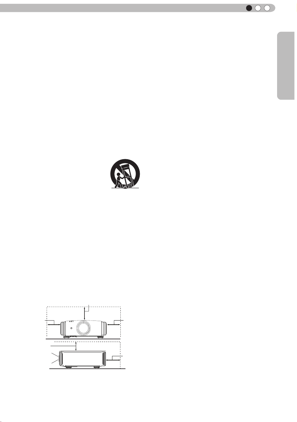
150 mm and above
300 mm
and above
200 mm
and above
300 mm
and above
150 mm
and above
PORTABLE CART WARNING
(symbol provided by RETAC)
S3126A
- All warnings on the product and in the operating
instructions should be adhered to.
- All operating instructions should be followed.
- Place the projector near a wall outlet where the
plug can be easily unplugged.
- Unplug this product from the wall outlet before
cleaning. Do not use liquid cleaners or aerosol
cleaners. Use a damp cloth for cleaning.
- Do not use attachments not recommended by the
product manufacturer as they may be hazardous.
- Do not use this product near water. Do not use
immediately after moving from a low temperature
to high temperature, as this causes condensation,
which may result in re, electric shock, or other
hazards.
- Do not place this product on an unstable cart,
stand, or table. The product may fall, causing
serious injury to a child or adult, and serious
damage to the product. The product should be
mounted according to the manufacturer’s
instructions, and should use a mount recommend
ed by the manufacturer.
- When the product is used on a
cart, care should be taken to avoid
quick stops, excessive force,
and uneven surfaces which may
cause the product and cart to
overturn, damaging equipment or
causing possible injury to the
operator.
- Slots and openings in the cabinet are provided for
ventilation. These ensure reliable operation of the
product and protect it from overheating. These
openings must not be blocked or covered. (The
openings should never be blocked by placing the
product on bed, sofa, rug, or similar surface. It
should not be placed in a built-in installation such
as a bookcase or rack unless proper ventilation is
provided and the manufacturer’s instructions have
been adhered to.)
- To allow better heat dissipation, keep a clearance
between this unit and its surrounding as shown
below. When this unit is enclosed in a space of
dimensions as shown below, use an air-conditioner
so that the internal and external temperatures are
the same. Overheating can cause damage.
Front
- power source indicated on the label. If you are
not sure of the type of power supply to your
home, consult your product dealer or local
power company.
- This product is equipped with a three-wire plug.
This plug will t only into a grounded power
outlet. If you are unable to insert the plug into
the outlet, contact your electrician to install the
proper outlet. Do not defeat the safety purpose
of the grounded plug.
- Power-supply cords should be routed so that
they are not likely to be walked on or pinched
by items placed upon or against them. Pay
particular attention to cords at doors, plugs,
receptacles, and the point where they exit from
the product.
- For added protection of this product during a
lightning storm, or when it is left unattended and
unused for long periods of time, unplug it from
the wall outlet and disconnect the cable system.
This will prevent damage to the product due to
lightning and power line surges.
- Do not overload wall outlets, extension cords, or
convenience receptacles on other equipment as
this can result in a risk of re or electric shock.
- Never push objects of any kind into this product
through openings as they may touch dangerous
voltage points or short out parts that could result
in a re or electric shock. Never spill liquid of
any kind on the product.
- Do not attempt to service this product yourself
as opening or removing covers may expose you
to dangerous voltages and other hazards. Refer
all service to qualied service personnel.
- Unplug this product from the wall outlet and
refer service to qualied service personnel
under the following conditions:
a)When the power supply cord or plug is damaged.
b)If liquid has been spilled, or objects have fallen on
the product.
c)If the product has been exposed to rain or water.
d)If the product does not operate normally by
following the operating instructions. Adjust only
those controls that are covered by the Operation
Manual, as an improper adjustment of controls may
result in damage and will often require extensive
work by a qualied technician to restore the product
to normal operation.
e)If the product has been dropped or damaged in any
way.
f) When the product exhibits a distinct change in
performance, this indicates a need for service.
- When replacement parts are required, be sure
the service technician has used replacement
parts specied by the manufacturer or with
same characteristics as the original part.
Unauthorized substitutions may result in re,
electric shock, or other hazards.
- Upon completion of any service or repairs to
this product, ask the service technician to
perform safety checks to determine that the
product is in proper operating condition.
3
Page 4

1
Getting started
- The product should be placed more than one foot
away from heat sources such as radiators, heat
registers, stoves, and other products (including
ampliers) that produce heat.
- When connecting other products such as VCR’s,
and DVD players, you should turn off the power of
this product for protection against electric shock.
- Do not place combustibles behind the cooling fan.
For example, cloth, paper, matches, aerosol cans
or gas lighters that present special hazards when
over heated.
- Do not look into the projection lens while the
illumination lamp is turned on. Exposure of your
eyes to the strong light can result in impaired
eyesight.
- Do not look into the inside of this unit through
vents (ventilation holes), etc. Do not look at the
illumination lamp directly by opening the cabinet
while the illumination lamp is turned on. The
illumination lamp also contains ultraviolet rays and
the light is so powerful that your eyesight can be
impaired.
- Do not drop, hit, or damage the light-source lamp
(lamp unit) in any way. It may cause the light source lamp to break and lead to injuries. Do not
use a damaged light source lamp. If the light source lamp is broken, ask your dealer to repair it.
Fragments from a broken light-source lamp may
cause injuries.
- The light-source lamp used in this projector is a
high pressure mercury lamp. Be careful when
disposing of the light-source lamp. If anything is
unclear, please consult your dealer.
- Do not ceiling-mount the projector to a place which
tends to vibrate; otherwise, the attaching xture of
the projector could be broken by the vibration,
possibly causing it to fall or overturn, which could
lead to personal injury.
- Use only the accessory cord designed for this
product to prevent shock.
- For health reasons, please take a break of about
5-15 minutes every 30-60 minutes and let your
eyes rest. Please refrain from watching any 3D images when you feel tired, unwell or if you feel
any other discomfort. Moreover, in case you see a
double image, please adjust the equipment and
software for proper display. Please stop using the
unit if the double image is still visible after
adjustment.
- Once every three years, please perform an internal
test. This unit is provided with replacement parts
needed to maintain its function (such as cooling
fans). Estimated replacement time of parts can
vary greatly depending on frequency of use and
the respective environment. For replacement,
please consult your dealer, or the nearest
authorized JVC service center.
- When xing the unit to the ceiling, Please note that
we do not take any responsibility, even during the
warranty period, if the product is damaged due to
use of metal xtures used for xation to the ceiling
other than our own or if the installation
environment of said metal xtures is not
appropriate. If the unit is suspended from the
ceiling during use, please be careful in regard to
the ambient temperature of the unit. If you use
a central heating, the temperature close to the
ceiling will be higher than normally expected.
- Video images can burn into the electronic com
ponent parts. Please do not display screens with
still images of high brightness or high contrast,
such as found in video games and computer
programs. Over a long period of time it might
stick to the picture element. There is no problem
with the playback of moving images, e.g. normal
video footage.
- Not using the unit for a long time can lead to
malfunction. Please power it on and let it run
occasionally. Please avoid using the unit in a
room where cigarettes are smoked. It is impos
sible to clean optical component parts if they are
contaminated by nicotine or tar. This might lead
to performance degradation.
- Please watch from a distance three times the
height of the projected image size. Persons with
photosensitivity, any kind of heart disease, or
weak health should not use 3D glasses.
- Watching 3D-images might be cause of illness.
If you feel any change in your physical condition,
please stop watching immediately and consult a
physician if necessary.
- When watching 3D images, it is recommended
to take regular breaks. As the length and
frequency of the required breaks differ for every
person, please judge according to your own
condition.
- If your child watches while wearing 3D glasses,
it should be accompanied by its parents or an
adult guardian. The adult guardian should be
careful to avoid situations where the child’s eyes
might become tired, as responses to tiredness
and discomfort, etc., are hard to detect, and it is
possible for the physical condition to deteriorate
very quickly. As the visual sense is not yet fully
developed in children under the age of 6, please
consult a physician in regard to any problem
concerning 3D-images if necessary.
- Note that when using the 3D feature, the video
output may appear different from the original
video image due to image conversion on the
device.
DO NOT allow any unqualied person
*
to install the unit.
Be sure to ask your dealer to install the unit
(e.g.attaching it to the ceiling) since special
technical knowledge and skills are required
for installation. If installation is performed by
an unqualied person, it may cause personal
injury or electrical shock.
4
Page 5
Getting Started
Safety Precautions (Continued)
POWER CONNECTION
ENGLISH
For USA and Canada only
Use only the following power cord.
The power supply voltage rating of this product is
AC110V – AC240V. Use only the power cord
designated by our dealer to ensure Safety and EMC.
Ensure that the power cable used for the projector is
the correct type for the AC outlet in your country.
Consult your product dealer.
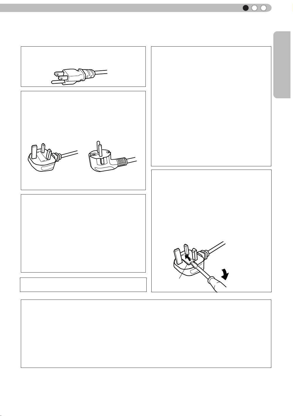
For United Kingdom For European continent
countries
Power cord
Power cord
WARNING:
Do not cut off the main plug from this
equipment.
If the plug tted is not suitable for the power points
in your home or the cable is too short to reach a
power point, then obtain an appropriate safety
approved extension lead or adapter or consult your
dealer. If nonetheless the mains plug is cut off,
dispose of the plug immediately, to avoid a possible
shock hazard by inadvertent connection to the main
supply. If a new main plug has to be tted, then
follow the instruction given below.
WARNING:
THIS APPARATUS MUST BE EARTHED.
IMPORTANT (Europe only):
The wires in the mains lead on this product are
colored Vert et jaune in accordance with the
following cord:
Green-and-yellow
Blue
Brown
As these colors may not correspond with the
colored making identifying the terminals in your
plug, proceed as follows:
The wire which is colored green-and-yellow must
be connected to the terminal which is marked M
with the letter E or the safety earth or colored
green or green-and-yellow. The wire which is
colored blue must be connected to the terminal
which is marked with the letter N or colored black.
The wire which is colored brown must be
connected to the terminal which is marked with the
letter L or colored red.
:Earth
:Neutral
:Live
POWER CONNECTION
(United Kingdom only)
HOW TO REPLACE THE FUSE:
When replacing the fuse, be sure to use only a
correctly rated approved type, re-t the fuse cover.
IF IN DOUBT —— CONSULT A COMPETENT
ELECTRICIAN.
Open the fuse compartment with the blade
screwdriver, and replace the fuse.
(* An example is shown in the illustration below.)
Fuse
Dear Customer,
This apparatus is in conformance with the valid European directives and standards regarding
electromagnetic compatibility and electrical safety.
European representative of Victor Company of Japan, Limited is:
JVC Technical Services Europe GmbH
Postfach 10 05 04
61145 Friedberg
Germany
5
Page 6
1
Getting started
ENGLISH
Information for Users on Disposal of Old Equipment and Batteries
[European Union only]
These symbols indicate that equipment with these symbols
should not be disposed of as general household waste. If you
want to dispose of the product o r battery, please consider the
collection systems or fa cilities for appr opriate recycling.
Notice: The sign Pb below the symbol for batteries indicates that
this battery contains lead.
Products
Battery
DEUTSCH
Benutzerinformationen zur Entsorgung alter Geräte und Batterien
[Nur Europäische Union]
Diese Symbole zeigen an, dass derartig gekennzeichnete Geräte
nicht als normaler Haushaltsabfall entsorgt werden dürfen. We
nden Sie sich zur Entsorgung des Produkts oder der Batterie an
die hierfür vorgesehenen Sammelstellen oder Einrichtungen,
damit eine fachgerechte Wiederverwertung möglich ist.
Produkte
dass diese Batterie Blei enthält.
Batterie
Hinweis: Das Zeichen Pb unterhalb des Batteriesymbols gibt an,
FRANÇAIS
Informations relatives à l’élimination des appareils et des piles usagés, à
l’intention des utilisateurs
[Union européenne seulement]
Si ces symboles gurent sur les produits, cela signie qu’ils ne
doivent pas être jetés comme déchets ménagers. Si vous voulez
jeter ce produit ou cette pile, veuillez considérer le système de
collection de déc hets ou les centres de recyclage appropriés.
Notication: La marque Pb en dessous du symbole des piles
Produits
Pile
indique que cette pile contient du plomb.
Informatie voor gebruikers over het verwijderen van oude apparatuur en
batterijen
[Alleen Europese Unie]
Deze symbolen geven aan dat appara tuur met dit symbool niet
mag worden weggegooid als algemeen huishoudelijk afval. Als u
het product of de batterij wilt weggooien, kun t u inzamelsystemen
of faciliteiten voor een geschikte recycling gebruiken.
Opmerking: Het teken Pb onder het batterijsymboo l geeft aan
dat deze batterij lood bevat.
Batterij
Producten
6
NEDERLANDS
Page 7
Getting Started
ENGLISH
ESPAÑOL / CASTELLANO
Información para los usuarios sobre la eliminación de baterías/pilas usadas
Estos símbolos indican que el equipo con estos símbolos no debe
desecharse con la basura doméstica. Si desea desechar el pro
ducto o batería/pila, acuda a los sistemas o centros de recogida
para que los reciclen debidamente.
Atención: La indicación Pb debajo del símbolo de batería/pila
indica que ésta contiene plomo.
Productos
Baterías/pilas
[Sólo Unión Europea]
ITALIANO
Informazioni per gli utenti sullo smaltimento delle apparecchiature e batterie
obsolete
[Solo per l’Unione Europea]
Questi simboli indicano che le apparecchiature a cui sono relativi
non devono essere smaltite tra i riuti domestici generici. Se si
desidera smaltire questo prodotto o questa batteria, prendere in
considerazione i sistem i o le strutture di raccolta appropriati per
il riciclaggio corretto.
Nota: Il simbolo Pb sotto il simbolo delle batter ie indica che
Prodotti
questa batteria contiene piombo.
Batteria
PORTUGUÊS
Informação para os utilizadores acerca da eliminação de equipamento usado e
pilhas
[Apenas União Europeia]
Estes símbolos indicam que o equipamento com estes símbolos
não deve ser eliminado juntamente com o restante lixo doméstico.
Se p retende eliminar o produto ou a pilha, utilize os sistemas de
recolha ou instalações para uma reciclagem apropriada.
Aviso: O sinal Pb abaixo do símbolo para pilhas indica que esta
pilha contém chumbo.
Produtos
Πληροφορίες για την απόρριψη παλαιού εξοπλισμού και μπαταριών
[ Ευρωπαϊκή Ένωση μόνο ]
Αυτά τα σύμβολα υποδηλώνουν ότι ο εξοπλισμός που τα φέρει
δεν θα πρέπει να απορριφθεί ως κοινό οικιακό απόρριμμα . Εάν
επιθυμείτε την απόρριψη αυτού του προϊόντος ή αυτής της
μπαταρίας , χρησιμοποιήστε το σύστημα περισυλλογής ή
εγκαταστάσεις για ανάλογη ανακύκλωση .
Σημείωση : Το σύμβολο Pb κάτω από το σύμβολο μπαταρίας
Προϊόντα
υποδηλώνει ότι η μπαταρία περιέχει μόλυβδο .
Pilha
ΕΛΛΗΝΙΚΑ
Μπαταρία
7
Page 8
1
Getting started
Brugerinformation om bortskaffelse af gammelt udstyr og batterier
DANSK
Disse symboler angiver, at udstyr med disse symboler ikke må
bortskaffes som almindeligt husholdningsaffald. Hvis du ønsker at
smide dette produkt eller batteri ud, bedes du overveje at bruge
indsamlingssystem et eller steder, hvor der kan ske korrekt gen
brug.
Bemærk: Tegnet Pb under symbolet for batterierne angiver, at
Produkter
dette batteri indeholder bly.
Batteri
[Kun EU]
SUOMI
Tietoja vanhojen laitteiden ja akkujen hävittämisestä
[Vain Euroopan unioni]
Nämä symbolit ilmaisevat, että symboleilla merk ittyä laitetta ei
tulisi hävittää tavallisen kotitalousjätteen mukana. Jos haluat hävit
tää tuotteen tai sen akun, tee se hyödyntämällä akkujen
keräyspisteitä tai muita kier rätyspaikkoja .
Huomautus: Akkusymbolin alapuolella oleva Pb-merk intä tarkoit
taa, että akku sisältää lyijyä.
Tuotteet
Akku
SVENSKA
Information för användare gällande bortskaffning av gammal utrustning och
batterier
[Endast den Europeiska unionen]
Dessa symboler indikerar att utrustning med dessa symboler inte
ska hanteras som vanligt hushållsavfall. Om du vill bortsk affa
produkten eller batteriet ska du använda uppsamlingssystem eller
inrättningar för lämplig återvinning.
Observera! Märkningen Pb under symbolen för batterier indikerar
att detta batteri innehåller bly.
Batteri
Produkter
NORSK
Opplysninger til brukere om kassering av gammelt utstyr og batterier
[Bare EU]
Disse symbolene viser at utstyr med dette symbolet, ikke skal
kastes sammen med vanlig husholdningsavfall. Hvis du vil kass
ere dette produkte t eller batteriet, skal du vurdere å bruke innsam
lingssystemene eller andre muligheter for riktig gjenbruk.
Merk: Tegnet Pb under symbolet for batterie r, viser at batteriet
Produkter
inneholder bly.
Batteri
8
Page 9
Getting Started
ENGLISH
Сведения для пользователей по утилизации старого оборудования и
батарей
[только для Европейского союза]
Данные символы указывают на то, что оборудование, на
которое они нанесены, не должны утилизироваться, как
обычные бытовые отходы. При необходимости утилизировать
такое изделие или батарею обратитесь в специальный пункт
сбора для их надлежащей переработки.
Уведомление: Надпись Pb под символом батар ей указывает
Изделия
на то, что данная батарея содержит свинец.
Батарея
Informace pro uživatele k likvid aci starého zařízení a baterií
[Pouze Evropská unie]
Tyto symboly označují, že produkty s těmito symboly se nesmí
likvidovat jako běžný odpad. Pokud chcete produkt nebo baterii
zlikvidovat, využijte sběrný systém nebo jiné zařízení, které zaji stí
řádnou recyklaci.
Upozornění: Značka Pb pod symbolem pro ba te rie znamená, že
Produkty
tato baterie obsahuje olovo.
Baterie
Informacje dla użytkowników dotyczące poz bywania się zużytego sprzętu i
baterii
[Tylko kraje Unii Europejskiej]
Te symbole oznaczają, że sprzę tu nie należy wyr zucać razem z
odpadami gospodarczymi. Jeśli trzeba po zbyć się tego produktu
lub ba terii, proszę skorzystać z systemu odbioru lub urządzeń do
zbió rki odpadów elektronicznych, w celu odpowiedniego ponowne
go ich przetworzenia.
Uwaga: Oznaczenie Pb, znajdujące się pod symbole m baterii
Produkty
wskazuje, że ta bateria zawiera ołów.
Felhasználói információ az elhasznált be rendezések és akkumulátorok
elhelyezéséről
[Csak az Európai Unióban]
Ez a szimbólum azt jelzi, hogy a berendezés nem helyezhető az
általános háztartási hulladék közé. Ha meg szeretne szabadulni a
terméktől vagy az akkumulátortól, akkor legyen tekintettel az
gyűjtő rendszerre vagy intézményekre a megfelelő hasznosítás
érdekében.
Megjegyzés: Az alábbi Pb szimbólum - ha az akkum ulátoron
Termékek
megtalálható - azt jelzi, hogy az akkumulátor ólmot
tartalmaz.
POLSKI
Bateria
MAGYAR
Akkumulátor
9
Page 10

1
Getting started
Contents
Getting started
Safety Precautions ...........................2
Contents .........................................10
Accessories/Optional
Accessories ....................................11
Check the Accessories .............................. 11
Optional Accessories ................................. 11
Controls and features ....................12
Main body - Front ......................................12
Main body - Bottom ...................................12
Main body - Rear ....................................... 13
Main body - About the indicator display .....14
Main body - Warning display and
conrmation/response ...............................15
Main body - Input terminal ......................... 16
How to insert batteries into the remote
control ........................................................ 17
Preparation
About installation ...........................18
IImportant points concerning the
installation .................................................18
Installing the Projector and Screen ...........19
Set Angle ................................................19
Shift .......................................................19
Fixation of the projector ............................. 20
Screen Size and Projection Distance ........ 21
Effective Range of Remote Control Unit....21
About the connection .....................22
Types of possible input signals
(PC compatible) ......................................... 22
Connection to the unit ...............................23
Connection of the power cord (provided) ..29
Operation
Basic Operation ..............................30
Basic operation procedures ....................... 30
Frequently used useful functions ............... 32
Setting the Screen Size ............................. 32
Masking the Surrounding Area of
an Image ...................................................33
Temporary turning-off of the video ..........34
Adjustment of the keystone correction ...34
Adjustments and settings
in the menu .....................................35
Structure of the menu hierarchy
(summary) .................................................35
Menu operation button ..............................41
Menu operation procedure ........................42
Menu item description ...............................43
Operation guide (glossary) ............53
Maintenance
Explanation of the installation/
removal of the lamp attachment ..58
Lamp attachment replacement
procedures ................................................ 58
Lamp attachment removal procedure ....... 60
Attachment of the installation
verication seal .......................................... 61
Replacing the Lamp .......................62
Lamp replacement procedure ...................62
Resetting lamp Time ..................................64
Method for cleaning and
replacing lters ...............................66
Others
Troubleshooting .............................68
In case this message is
displayed .........................................70
RS-232C Interface ...........................71
RS-232C Specications ............................71
TCP/IP-connection ....................................71
Command Format .....................................72
RS-232C Communication Examples ......... 74
Copyright and Caution ...................75
About Trademarks and Copyright ..............75
Caution ......................................................75
Specications .................................76
Dimensions ................................................ 78
Index ................................................79
10
Page 11

Getting Started
ENGLISH
Accessories/Optional Accessories
Check the Accessories
Remote Control ..........................................................................1 piece
AAA size Batteries (for operation conrm)..................................2 pieces
Power Cord For the US market (2 m) .........................................1 piece
Power Cord For the EU market (2 m) .........................................1 piece
Power Cord For the UK market (2 m) .........................................1 piece
Lamp Attachment .......................................................................1 piece
Installation Verication Seal........................................................1 piece
●
Instruction manual, warranty card and other printed material are also included.
Optional Accessories
Please check with your authorized dealer for details.
●
Replacement Lamp: PK-L2210U
●
Replacement Filter: PC010661199
●
Replacement lamp attachment: PC010685599
●
3D-Glasses: PK-AG1
●
3D Synchro Emitter: PK-EM1
11
Page 12
1
Getting started
Controls and features
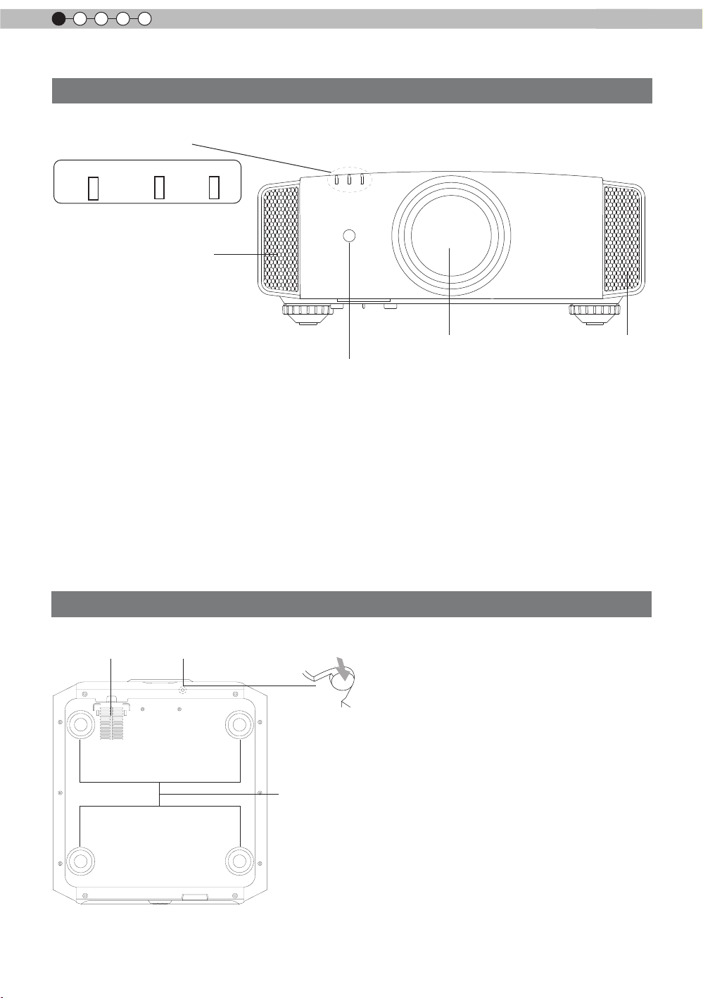
Main body - Front
③ Indicator
STANDBY/ON LAMP WARNING
④ Exhaust Vent
① Lens
This is a projection lens. Please do not look
inside during projection.
② Remote receiver (front)
Please aim the remote control at this area when
using it.
* There is also a remote receiver at the rear.
Main body - Bottom
⑤ Inlets
⑥ Manual button for
lens cover
① Lens
④ Exhaust
② Remote receiver (front)
③ Indicator
Please see “About the indicator display” for
details. (Reference page: 14)
④ Exhaust Vent
Warm air ows out in order to cool the interior of
the set. Please do not block the vents.
⑤ Inlets (at 3 points on the rear/
bottom)
In order to cool the inside of the unit, air is let
inside. Do not block or prevent the outow of
hot air. Doing so could lead to failure of the unit.
* There are inlets at two points on the right and
left sides of the rear side. (Reference page: 13)
Vent
12
⑦ Feet
⑥ Manual operation button of the
lens cover
The lens cover can be opened when pressed
down.It is used for maintenance and not used
during normal use.
⑦ Feet
The height (0 to 5 mm) can be adjusted by
turning the foot.
Page 13
Getting Started
ENGLISH
Controls and features (continued)
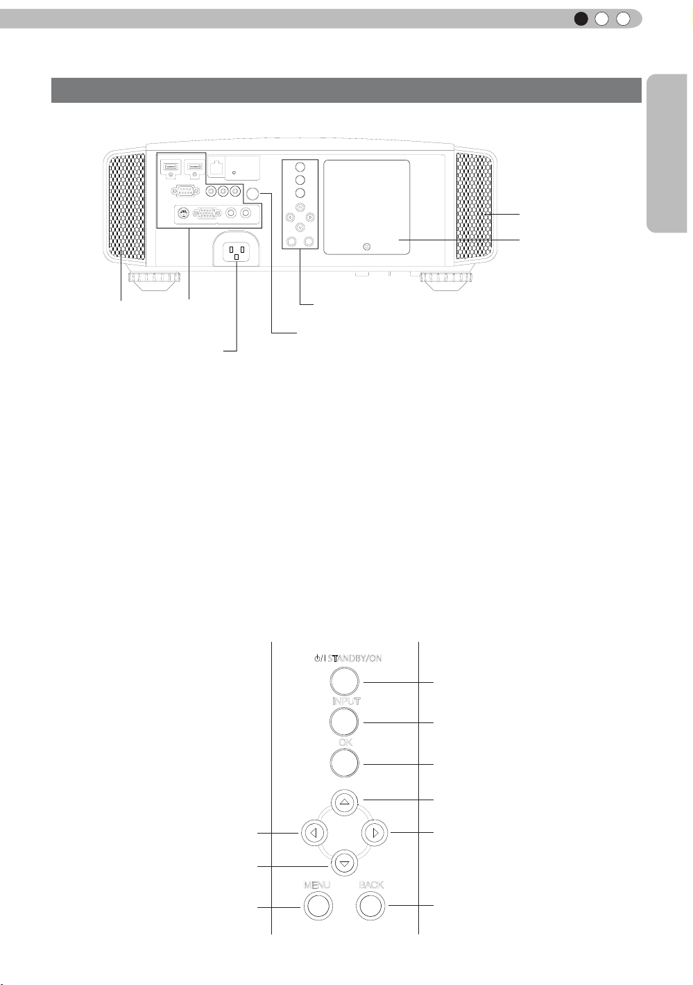
Main body - Rear
⑤ Inlets
⑨ Lamp Cover
⑤ Inlets
⑧ Input
terminal
⑫ Power input
terminal
⑧ Input terminal
There is also a terminal other than the input
terminal for video images, such as those used
for controlling or optional equipment. Please see
“
About input terminals” for detailed information
about terminals. (Reference page: 16)
⑨ Lamp Cover
When replacing the light source lamp, remove
this cover. (Reference page: 62)
⑩ Operation panel
See the following illustration “Control panel” for
more details.
Operation panel
■
⑩ Operation panel
⑪ Light receiving section
of the remote control (rear)
⑪ Light receiving section of the
remote control (rear)
Please aim the remote control at this section
when using.
* There is also a light receiving section at the
rear.
⑫ Power input terminal
This is the power input terminal. It is
connected via the supplied power cord.
(Reference page: 29)
STANDBY/ON
To turn on/off the power
INPUT
To switch input
OK
To select or conrm
To display the menu
Left button
Down button
MENU
BACK
Up button
Right button
eturn to the previous menu
To r
13
Page 14
1
Getting started
Controls and features (continued)
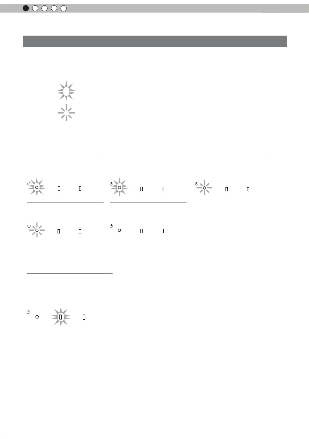
Main body - About the indicator display
Warnings and indications used during normal operation mode of this unit are displayed with the indicators
for [STAND BY / ON], [LAMP], [WARNING] at the front of this unit.
Meaning of the lighting gures:
The display the indicator lights.
They display ashing of the indicator.
Operation mode display
Displays the color and lighting/ashing of the [STAND BY / ON] indicator.
STAND BY
Duringstandby
STANDBY/ON
STAND BY
When"Hide"issettoON
STANDBY/ON
Light on(Red)
LAMP WARNING
Blinking(Green)
LAMP WARNING
STAND BY
Whileactivatingthelamp
(about1minute)
STANDBY/ON
All Off
Duringimageprojection
STANDBY/ON
Light on(Green)
LAMP WARNING
LAMP WARNING
STAND BY
Duringcooldown
STANDBY/ON
Blinking(Red)
LAMP WARNING
Criterion indication of the lamp replacement
Displays lighting/ashing of the [LAMP] indicator. Moreover, the [STAND BY / ON] indicator, which shows
the operation mode of this unit, is displayed as described above. (Reference page: 76)
LAMP Light on(orange)
Lamp replacement is
near(When accumulated lamp
time has exceeded 2900 hours)
STANDBY/ON
LAMP WARNING
14
Page 15
Getting Started
ENGLISH
Controls and features (continued)
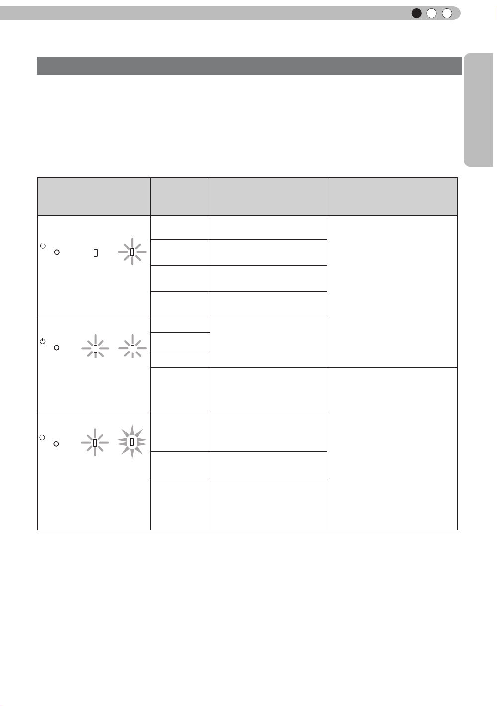
Main body - Warning display and conrmation/response
Warning display
You are informed of the contents of warning notices by the (repeated) displays of the [WARNING] and
[LAMP] indicators. Moreover, the [STAND BY / ON] indicator, which shows the operating mode of the unit,
is displayed simultaneously as described above.
Upon activation of the warning mode, the projection is interrupted at the same time for about 60 seconds
and the cooling fan is turne
ooling fan has stopped. Subsequently, please perform the following checks and take appropriate
c
countermeasures.
d on. Please disconnect the power plug from the electric socket after the
Lighting/flashing lights
status diagram
STANDBY/ON
LAMP WARNING
red
(
) (
red
red
)
)
Mode
display
STANDBY/ON
Mode
display
STANDBY/ON
Mode
display
(*)
LAMP WARNING
orange
(
Simultaneous
ashing
LAMP WARNING
orange
(
) (
Blinking
Frequency
1 time
2 times Cooling fan stops
3 times
4 times
1 time
2 times
3 times
)
4 times
1 time
2 times
Abnormalities in the power
supply
Internal temperature is too
high
External temperature is
too high
Abnormal electrical circuit
If something is wrong with
the automatic lens cover
Lamp does not light up
and unit is unable to
project
Lamp is turned off during
projection
Content
Conrmation and
countermeasures
●
Check that nothing is
blocking the air inlets.
●
Check that the external
temperature is normal.
Action
Leave the unit until it cools
down.
After that, turn on the power
again.
●
Check that an impact shock
has not occurred during
operation.
●
Check that the lamp
unit and lamp cover are
correctly installed.
●
Check that nothing is
blocking the auto lens
cover.
If the warning indication is displayed again, please wait for the cooling fan stopped, then pull out the power
plug from the power outlet. Then call your authorized dealer for repair.
(*)If the scheduled time for the replacement of the lamp is exceeded, the light might light up.
3 times
Lamp cover is removed
Action
Turn on the power again.
15
Page 16
1
Getting started
Controls and features (continued)
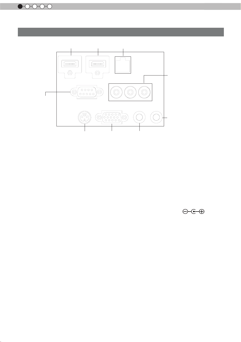
Main body - Input terminal
① HDMI 1 ② HDMI 2 ③ LAN
⑤ COMPONENT
④ RS-232C
⑨ REMOTE
⑥ 3D SYNCHRO
⑦ PC
① HDMI 1 Terminal
You can connect a device equipped with HDMI
output, etc. It is tted to the M3 lock hole.
Screw hole depth 3mm. (Reference page: 24)
② HDMI 2 Terminal
You can connect a device equipped with HDMI
output, etc. It is tted to the M3 lock hole.
Screw hole depth 3mm. (Reference page: 24)
③ LAN terminal “RJ-45”
This is a LAN-terminal. If one connects an
external PC, it is possible to control this unit by
sending control commands.
(Reference page: 28)
④ RS-232C terminal (male D-Sub 9
pin)
This is a RS-232C interface standard terminal.
If one connects an external PC, it is possible to
control this unit. (Reference page: 27)
⑤ COMPONENT terminal “RCAx3”
It is also used as input terminal for analog
RGB (G on Sync) signals, component (Y, Cb,
Cr) signals, DTV format (Y, Pb, Pr) signals. It
can also be connected with devices, which are
equipped with signal output, etc. (Reference
page: 25)
⑧ TRIGGER
⑥ 3D SYNCHRO terminal
3D synchro emitter: it is connected to the PKEM1 (sold separately) when enjoying 3D video
contents. (Reference page: 26)
⑦ PC terminal “D-Sub 15 pin”
This is an input term used for Personal Computer
(PC) signals only (RGB video signals and sync
signals). Use to connect a computer display
output terminal, etc. (Reference page: 26)
⑧ TRIGGER terminal( )
DC power supply output terminal with DC12V,
100mA. It is used for output signals which control
the vacillating screen responding to the SCREEN
TRIGGER. Please note it can cause damage
to your equipment if the connection is done
incorrectly. (Tip = DC +12 V, Sleeve = GND)
(Reference Page: 27, 51)
⑨ REMOTE terminal to “Stereo mini
jack”
In case it is impossible to use the remote control
due to the installation of this unit’s dedicated
BOX or rear projection, one can set up an
external light receiving section. It is used to
connect this external receiver and this unit. There
is no such product as an external light receptor.
Therefore, please consult your authorized JVC
service center. (Reference page: 28)
16
Page 17
Getting Started
ENGLISH
BACK
HIDE
LIGHT
C.M.D
PC
HDMI 1
STAND BY
ASPECT
HDMI 2
ANAMO
COMP
.
LENS.
CONTROL
MENU
GAMMA
AP
LENS.
ADJ.
PIC.
ON
NATURAL
3D
USER4
USER5 USER6
PICTURE MODE
COMPONENT
TEMP
COLOR
AUTO
ALIGNMENT
DYNAMIC
USER1
USER2
USER3
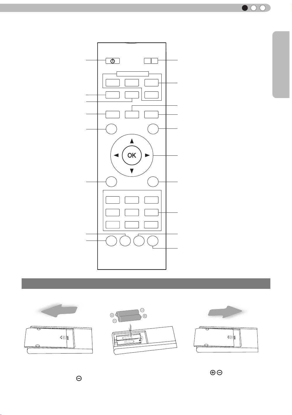
Controls and features (continued)
■
Remote Control
To turn off the power
To set the screen size
(Reference page: 32)
Anamorphic
To control lens
(Reference page: 30)
To hide the image
temporarily(Reference
page: 34)
To display/close the menu
(Reference page: 41)
To adjust color temperature
To set gamma
To turn on the power
To select input mode
(Reference page: 30)
Clear Motion Drive
Auto Alignment
(Reference page: 49)
To illuminate buttons on the remote
control for 7 second
To select or conrm
To return to the previous menu
(Reference page: 41)
To switch picture mode
Lens Aperture
Sequentially switched picture
adjust items, such as contrast and
brightness.The switching items are
not the same for different models, or
different picture modes.
How to insert batteries into the remote control
①
●
●
●
If the remote control has to be brought closer to the projector to operate, it means that the batteries are
wearing out.
When this happens, replace the batteries. Insert the batteries according to the
Be sure to insert the end rst.
If an error occurs when using the remote control, remove the batteries and wait for 5 minutes. Load the
batteries again and operate the remote control.
②
③
marks.
17
Page 18
2
CAUTION
CAUTION
CAUTION
Preparation
About installation
Important points concerning the installation
Please read the following carefully before the installation of this unit.
Installation environment
This unit is a precision device. Therefore, please refrain
from installation or use in the following locations.
Otherwise, it may cause re or malfunction.
• Dust, wet and humid locations.
• Sooty or cigarette smoke lled locations.
• On top of a carpet or bedding, or other soft surfaces.
• Locations with high temperatures - as located in direct
sunlight.
• Locations with high or low temperatures.
Permissible operating temperature range: +5 º to +35º .
Relative humidity range permissible for operating: 20%
~ 80% (non-condensing) .
Storage temperature tolerance: -10º to +60º.
• If the installation of the unit is done in a room with soot
and/or smoke over a longer period, even small amounts
of these substances will affect the device.This unit
cools its optical components, which produce a great
amount of heat, by sucking in air. If the optical circuits
get dirty, this might lead to malfunctions, like the video
images becoming darker or a deterioration of the color
development. Dirt sticking to the optical components
cannot be removed.
Please be careful to perform
the installation at a certain
distance from walls and
other devices
For better heat dissipation, please keep a minimum
distance between this unit and its surroundings as shown
in the following illustration.
oreover, please open the front of the unit. If there are
M
any objects in front of the exhaust port, the hot air will
ow back to the unit and heat it. The hot air owing out of
the unit might cause shadows on the screen (heat haze
phenomenon).
Moreover, when it is enclosed in a space as shown in the
following illustration, please make sure that the enclosed
interior has the same temperature as the outside. High
temperatures might lead to failure of the unit.
Please be careful when using
This unit uses a projection lamp, which will get hot when
in use. Please refrain from projecting in the following
circumstances.
Otherwise, it might cause re or malfunction.
• Projection while lying on its side.
Please avoid projection if the installation of the unit is
done at an excessive angle of more than ±
cause harm to the life of the lamp and color shading.
• Please avoid projection at a location where the air vents
or exhaust ports might get blocked.
Please choose a non-uniform cloth material for the screen.
If you choose something uniform, like something with a
checkered pattern, there might be interference with the
pixel array of the D-ILA components. One way to reduce
the interference pattern is to change the size of the screen,
so that it will not be so noticeable.
90 °. It may
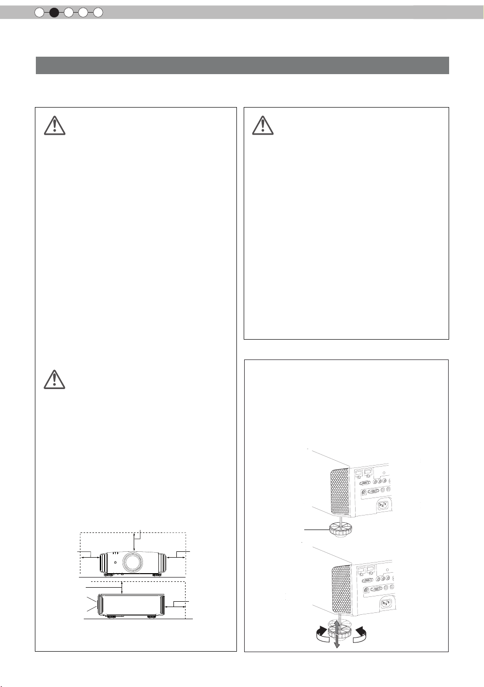
Inclination adjustment
for this unit
How to adjust the vertical angle
Height and inclination of the unit (0 ~ 5mm) can be
adjusted by rotating its feet. Lift the unit and adjust
the four feet.
150 mm and above
300 mm
and above
150 mm
and above
Front
18
300 mm
and above
200 mm
and above
Stand
Extend Contract
Page 19
ENGLISH
Horizontal lens shift
About installation (Continued)
Installing the Projector and Screen
While installing, please place this unit and the screen perpendicular to each other. Failing
to do so may increase trapezoidal distortion. (Reference page: 34, 49)
Set Angle
As shown in the illustration, this unit can be installed
with a tilted angle, but for some areas there might be
other conditions. Moreover, depending on the angle of
installation, it may be necessary to have a hanging metal
mount and secure installation base depending on the angle
of the installation.
Area A: The range where installation is possible.
Area B: The necessary range for the installation of the
lamp attachment. Please make sure to use the
supplied lamp attachment. (Reference page: 58)
Failure to attach it might cause equipment failure.
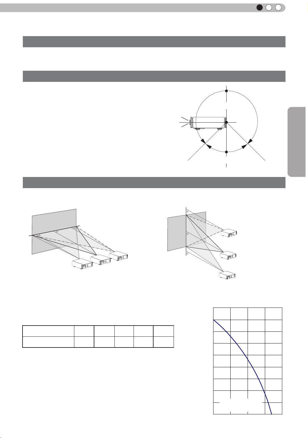
Shift
■
■
Left/Right position
0% up/down position (center)
*
Up/Down position
*
Downward slope
of 45 °
0% left/right position (center)
Area A
Area B
Downward slope
of 45 °
Preparation
Approximately 34%
(maximum) of the
projected image
Approximately 34%
(maximum) of the
projected image
Lens shift correlation chart:
Left-Right Shift(%)
Up-Down Shift(%)
●
Maximum Up-Down shift varies with the amount of Left-Right shift.
Likewise, maximum Left-Right shift varies with the amount of UpDown shift.
●
The values on the chart are intended to act as a guide. Use them
for reference during installation.
0% 10% 20% 30% 34%
80% 66% 47% 18% 0%
Approximately 80%
(maximum) of the
projected image
Approximately 80%
(maximum) of the
projected image
■
Lens shift movement
range
90
80
70
60
Vertical lens shift(%)
50
40
30
20
Lens movability
10
range
0 10 20
30 40
(%)
19
Page 20
2
Preparation
About installation (Continued)
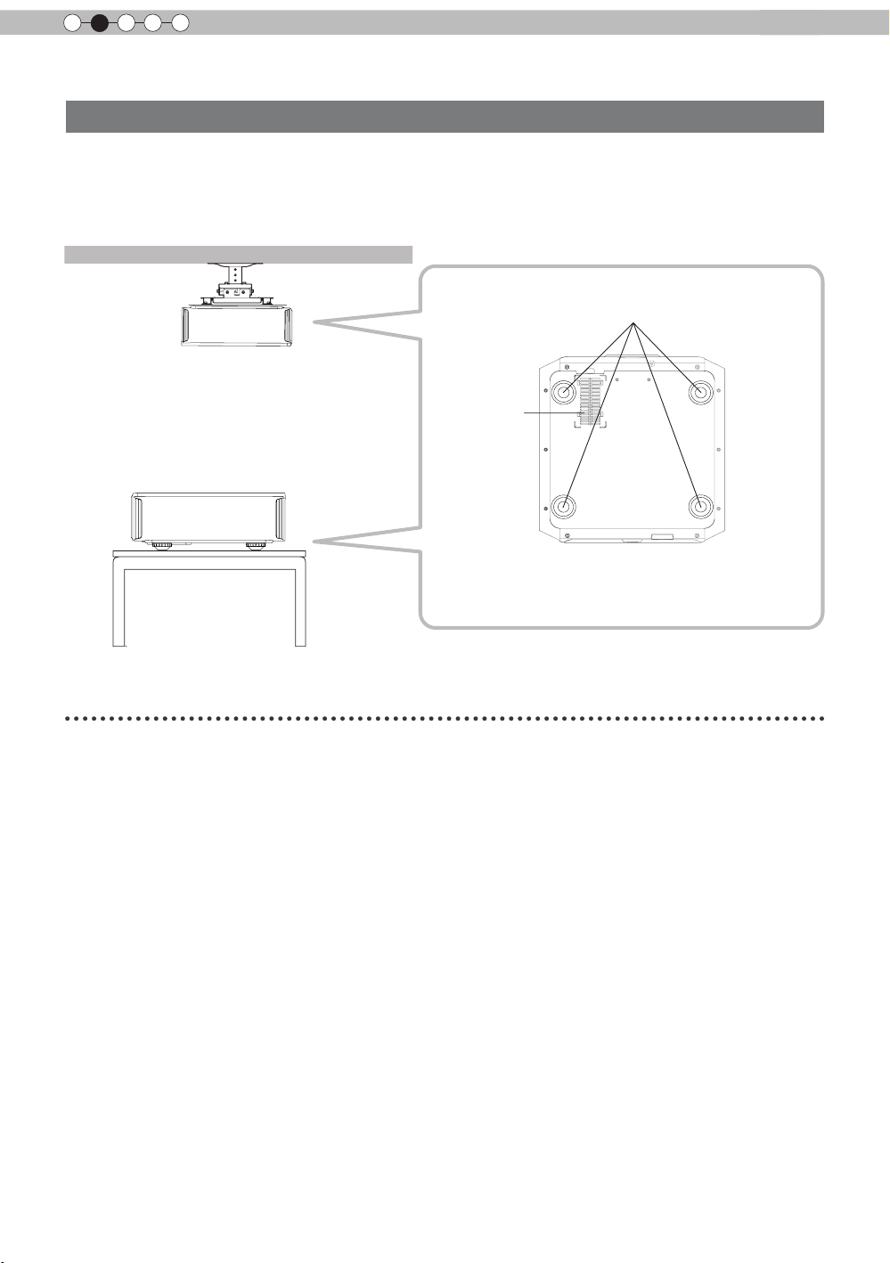
Fixation of the projector
Measures to prevent the unit from toppling or dropping should be taken for safety reasons and
accident prevention during emergencies including earthquakes.
When mounting this unit on a pedestal or ceiling, remove the 4 feet on the bottom surface and
use all the 4 screw holes (M5 screws) to mount.
Ceiling
Precautions for Mounting
●
Special expertise and techniques are required for
mounting this unit. Be sure to ask your dealer or a
specialist to perform mounting.
●
Depth of the screw holes (screw length) is 23
mm. Use screws shorter than 23 mm but longer
than 13 mm.
Using other screws will result in
malfunctioning or cause the unit to drop.
●
When mounting to a pedestal, ensure
sufcient space (foot height of 10 mm or
higher) around the unit so that the air inlets
are not blocked.
●
Do not tilt this unit more than ±5 degrees
from side to side when using.
■
Bottom Surface
4 locations
Air inlets
●
Regardless whether the unit is still under
guarantee, JVC is not liable for any product
damage caused by mounting the unit with non-
JVC ceiling ttings or when the environment is
not suitable for ceiling-mount.
●
When using the unit hanging from a ceiling,
pay attention to the surrounding temperature.
When a heater is in use, temperature around
the ceiling is higher than expected.
20
Page 21
ENGLISH
30°
30°
20°
20°
About installation (Continued)
Screen Size and Projection Distance
Determine the distance from the lens to the screen to achieve your desired screen size.
This unit uses a 2.0x power zoom lens for projection.
■
Relationship Between Projection Screen Size and Projection Distance
Pr o je c ti o n Sc re e n
Size
(Height, Width)
Aspect Ratio 16:9
"
60
Approx.
(
(Approx.0.9, 1.5m)
(Approx.1.0, 1.8m)
(Approx.1.1, 2.0m)
(Approx.1.2, 2.2m)
(Approx.1.4, 2.4m)
(Approx.1.5, 2.7m)
(Approx.1.6, 2.9m)
0.7, 1.3m)
70"
80"
90"
100"
110"
120"
130"
A p pr o x im a t e P r oj e c ti o n
Approx.2.09m to Approx.4.28m
Approx.2.40m to Approx.4.89m
Approx.2.70m to Approx.5.51m
Approx.3.01m to Approx.6.13m
Approx.3.31m to Approx.6.75m
pprox.3.62m to Approx.7.36m
A
Approx.3.92m to Approx.7.98m
Distance
W(Wide) to T(Tele)
Approx.1.78m to
Approx.3.66m
Projection Screen Size
(Height, Width)
Aspect Ratio 16:9
140"
(Approx.1.7, 3.1m)
150"
(Approx.1.9, 3.3m)
160"
(Approx.2.0, 3.5m)
170"
(Approx.2.1, 3.8m)
180"
(Approx.2.2, 4.0m)
190"
(Approx.2.4, 4.2m)
200"
(Approx.2.5, 4.4m)
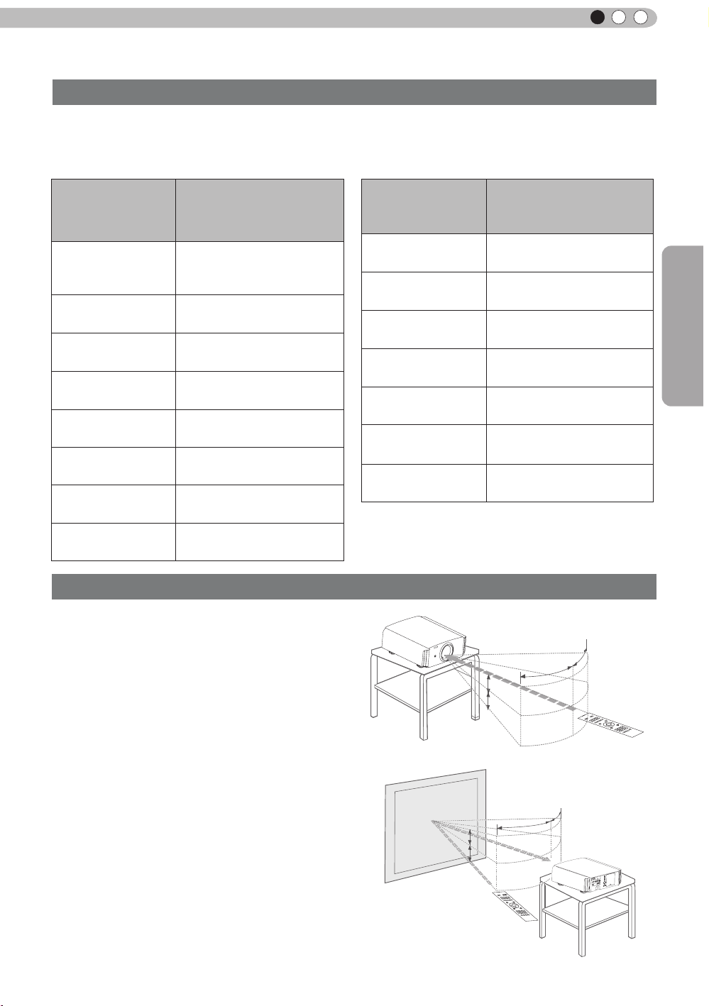
Effective Range of Remote Control Unit
A p pr ox im at e P ro je ct io n
Distance
W(Wide) to T(Tele)
Approx.4.23 m to
Approx.8.60m
Approx.4.53m to
Approx.9.22m
Approx.4.84m to
Approx.9.84m
Approx.5.14m to
Approx.10.45m
Approx.5.45m to
Approx.11.07m
Approx.5.75m to
Approx.11
Approx.6.06m to
Approx.12.30m
.68m
Preparation
When directing the remote control toward this
■
unit.
●
When aiming the remote control towards the
remote sensor on this unit, ensure that the
distance to the sensor in front or at the rear of
this unit is within 7 m.
●
If the remote control fails to work properly, move
closer to this unit.
When reecting off a screen
■
●
Ensure that the total of distance A between this
unit and screen and distance B between remote
control and screen is within 7 m.
●
As the efciency of signals reected from the
remote control unit differ with the type of screen
used, operable distance may decrease.
Screen
This unit
20°
A
20°
B
Remote control
30°
Remote control
30°
This unit
21
Page 22
2
Preparation
About the connection
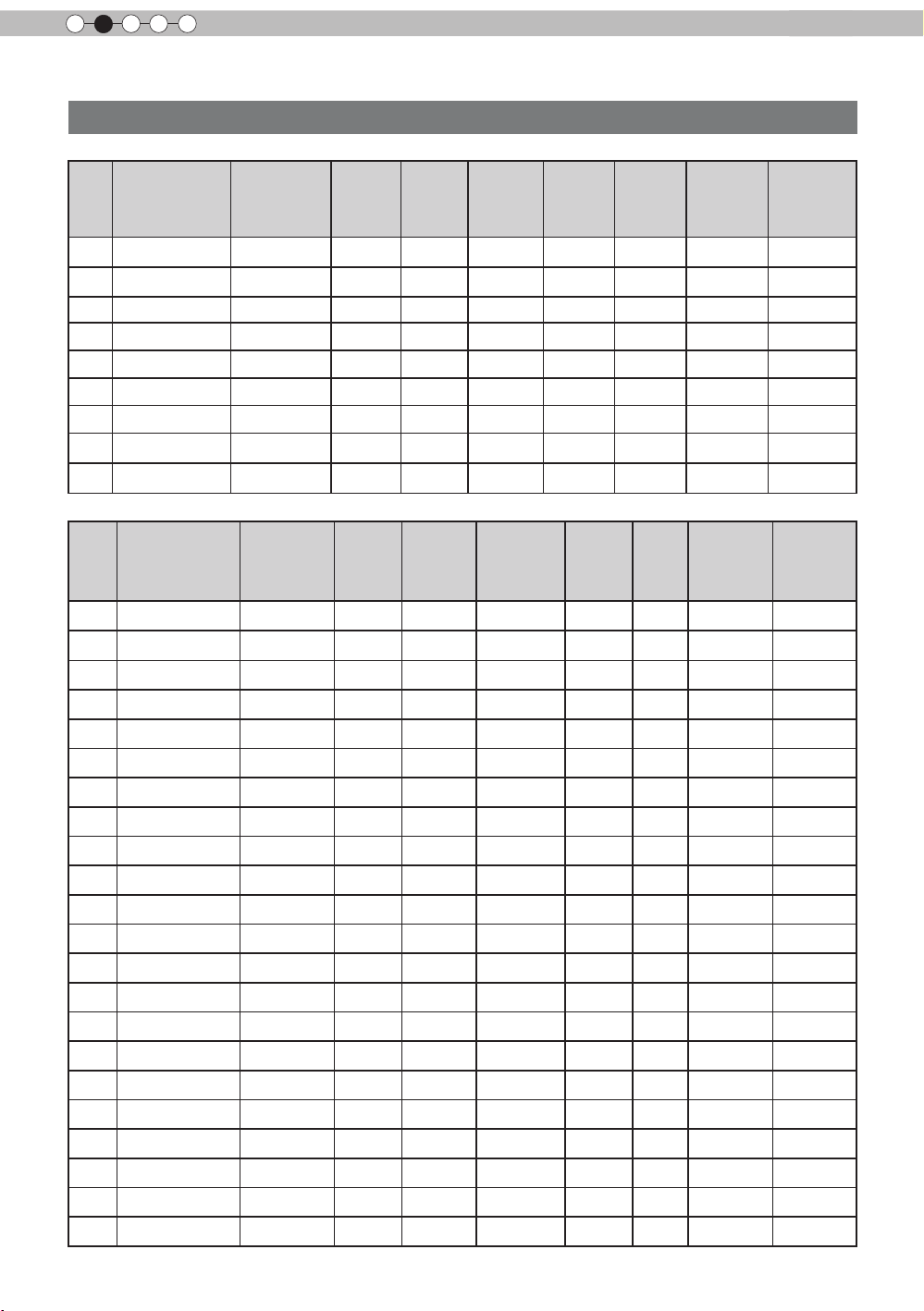
Types of possible input signals (PC compatible)
●
HDMI
No.
Designation
1
2
3
4
5
6
7
8
WSXGA
9
●
PC (D-sub 3-lines 15 pins)
No.
1
2
3
4
5
6
7
8
9
10
11
12
13
14
15
16
17
18
19 1920x1080 60 1
20
21
22
60 640 X 480 31.500 60.000 25.200 800 525 640 480
VGA
59.94 640 X 480 31.469 59.940 25.175 800 525 640 480
VGA
60 800 X 600 37.879 60.317 40.000 1,056 628 800 600
SVGA
60 1024 X 768 48.363 60.004 65.000 1,344 806 1,024 768
XGA
60 1280 X 768 47.760 60.000 79.998 1,675 796 1,280 768
WXGA
+60 1440 X 900 55.919 59.999 106.470 1,904 932 1,440 900
WXGA
60 1280 X 1024 63.981 60.020 108.000 1,688 1,066 1,280 1,024
SXGA
+60 1680 X 1050 65.222 60.002 147.140 2,256 1,087 1,680 1,050
WUXGA
60 1920 X 1200 74.038 59.95 154.000 2,080 1,235 1,920 1,200
Designation
60 640 X 480 31.500 60.000 25.175 800 525 640 480
VGA
72 640 X 480 37.900 72.000 31.500 832 520 640 480
VGA
75 640 X 480 37.500 75.000 31.500 840 500 640 480
VGA
85 640 X 480 43.300 85.000 36.000 832 509 640 480
VGA
56 800 X 600 35.200 56.000 36.000 1024 625 800 600
SVGA
60 800 X 600 37.900 60.000 40.000 1056 628 800 600
SVGA
72 800 X 600 48.100 72.000 50.000 1040 666 800 600
SVGA
75 800 X 600 46.900 75.000 49.500 1056 625 800 600
SVGA
85 800 X 600 53.700 85.000 56.250 1048 631 800 600
SVGA
60 1024 X 768 48.400 60.000 65.000 1344 806 1024 768
XGA
70 1024 X 768 56.500 70.000 75.000 1328 806 1024 768
XGA
75 1024 X 768 60.000 75.000 75.750 1312 800 1024 768
XGA
85 1024 X 768 68.700 85.000 94.500 1376 808 1024 768
XGA
60 1280 X 768 47.760 60.000 79.998 1675 796 1280 768
WXGA
WXGA+
SXGA
SXGA+
WSXGA+
60 1440 X 900 55.919 59.999 106.470 1904 932 1440 900
60 1280 X 1024 64.000 60.000 108.000 1688 1066 1280 1024
60 1400 X 1050 63.981 60.020 108.000 1688 1066 1400 1050
60 1680 X 1050 65.222
13" 640 X 480 35.000 66.667 30.240 864 525 640 480
MAC
16" 832 X 624 49.107 75.087 55.000 1120 654 832 624
MAC
19" 1024 X 768 60.241 74.927 80.000 1328 804 1024 768
MAC
Resolution
Resolution
920 X 1080 67.500 60.00 148.500 2200 1125 1920 1080
fh
[kHz]fv[Hz]
fh
[kHz]
60.002 147.140 2256 1087 1680 1050
dot CLK
[MHz]
fv
[Hz]
Total No.
of dots
[dot]
dot CLK
[MHz]
Total No.
of lines
[line]
Total No.
of dots
[dot]
Total
No. of
lines
[line]
No. of
effective
dots
[dot]
No. of
effective
dots
[dot]
No. of
effective
lines [line]
No. of
effective
lines [line]
22
Page 23

ENGLISH
About the connection (Continued)
Connection to the unit
●
Do not turn on the power until connection is complete.
●
The connection procedures differ according to the device used. For details, refer to the instruction
manual of the device to be connected.
●
This device is used for image projection. Connect to an audio output device such as amplier and
speaker for audio output from the connected device.
●
The images may not be displayed depending on the devices and cables to be connected.
For HDMI cable (sold separately), only use one that is HDMI-approved.
●
It may not be possible to connect to this unit depending on the dimension of the connector cover of the
cables to be connected.
BD/DVD Recorder BD/DVD Player
Preparation
To connect via HDMI
terminal
(Reference page: 24)
To connect RS232C terminal
(Reference
page: 27)
Connection by 3D SYNCHRO
terminal (Reference page: 26)
Connection by LAN terminal (Reference page: 28)
To connect via video terminal
STANDBY/ON
1 HDMI 2
RS-232-C
3D
SYNCHRO
C
R/PR CB/PB Y
PC
TRIGGER
REMOTE
CONTROL
INPUT
OK
MENU
BACK
Connection by REMOTE terminal (Reference page: 28)
To connect via Trigger terminal
To connect via PC terminal
(Reference page: 26)
(Reference page: 27)
(Reference page: 25)
PC
VCR and
camcorder
23
Page 24
2
1 HDMI 2
RS-232-C
3D
C
R/PRCB/PB
Y
SYNCHRO
PC
TRIGGER
REMOTE
CONTROL
STANDBY/ON
MENU
BACK
INPUT
OK
1 HDMI 2
RS-232-C
3D
C
R/PRCB/PB
Y
SYNCHRO
PC
TRIGGER
REMOTE
CONTROL
STANDBY/ON
MENU
BACK
INPUT
OK
Preparation
About the connection (Continued)
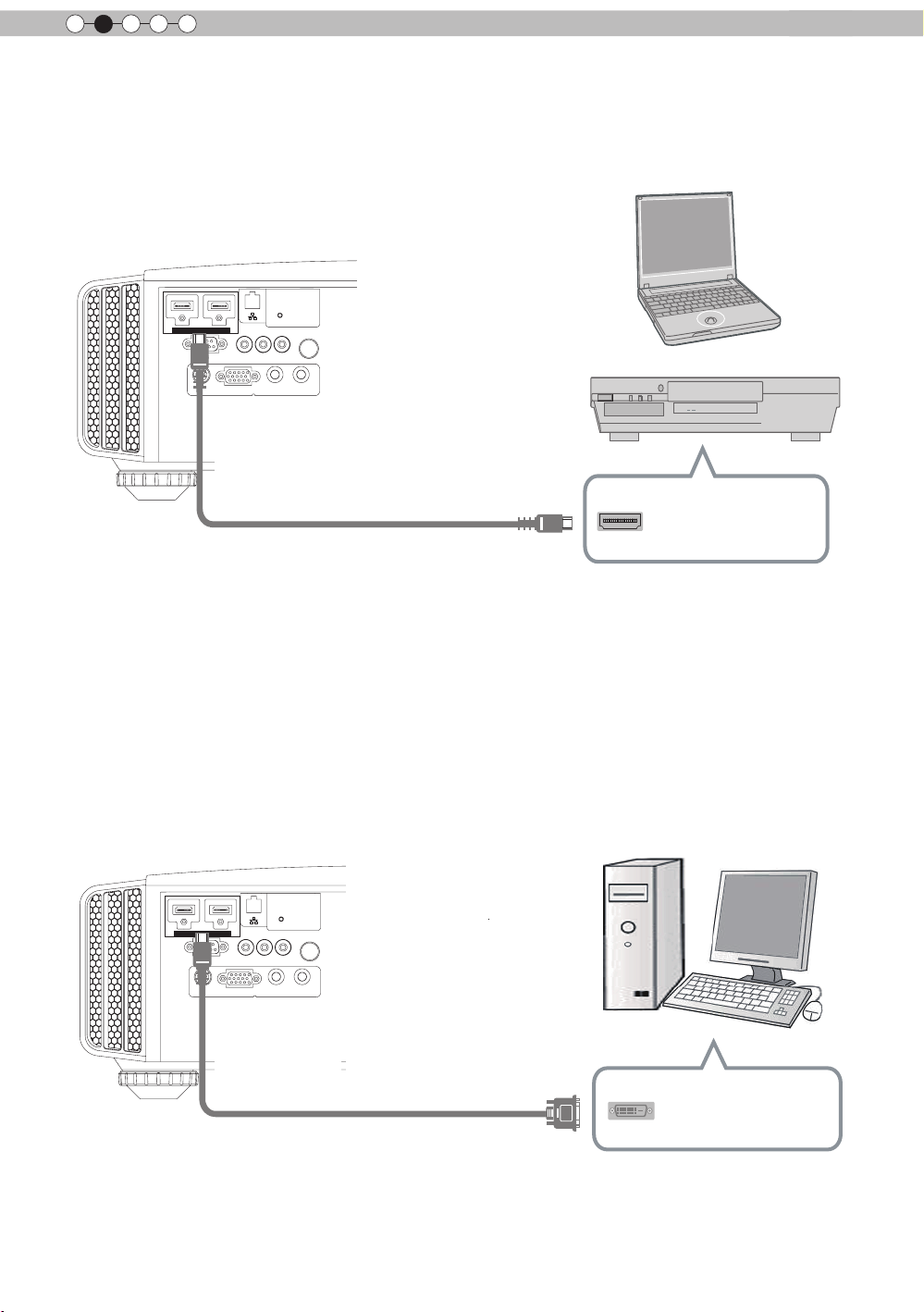
■
Connecting via HDMI Cable
This unit
Notebook PC
BD/DVD recorder
HDMI 1 input terminal
HDMI 2 input terminal
HDMI output terminal
HDMI cable (sold separately)
●
If noise is produced, take PCs (Notebook PC) away from this unit.
●
For a transmission bandwidth in compliance with the HDMI standard, a 340MHz cable is recommended
In case a cable is used for transmission bandwidth of 75MHz, it is recommended to choose 1080i or less
for the transmitting equipment.
●
If the video is not displayed, try to reduce the length of the cable or lowering the resolution of the video
transmitting equipment.
■
Connecting via HDMI-DVI Conversion Cable
This unit
HDMI 1 input terminal
HDMI 2 input terminal
●
If noise is produced, take PCs (desktop computer) away from this unit.
●
If the video is not displayed, try to reduce the length of the cable or lowering the resolution of the video
HDMI-DVI conversion cable
transmitting equipment.
24
(sold separately)
Desktop computer
DVI output terminal
Page 25
ENGLISH
C
About the connection (Continued)
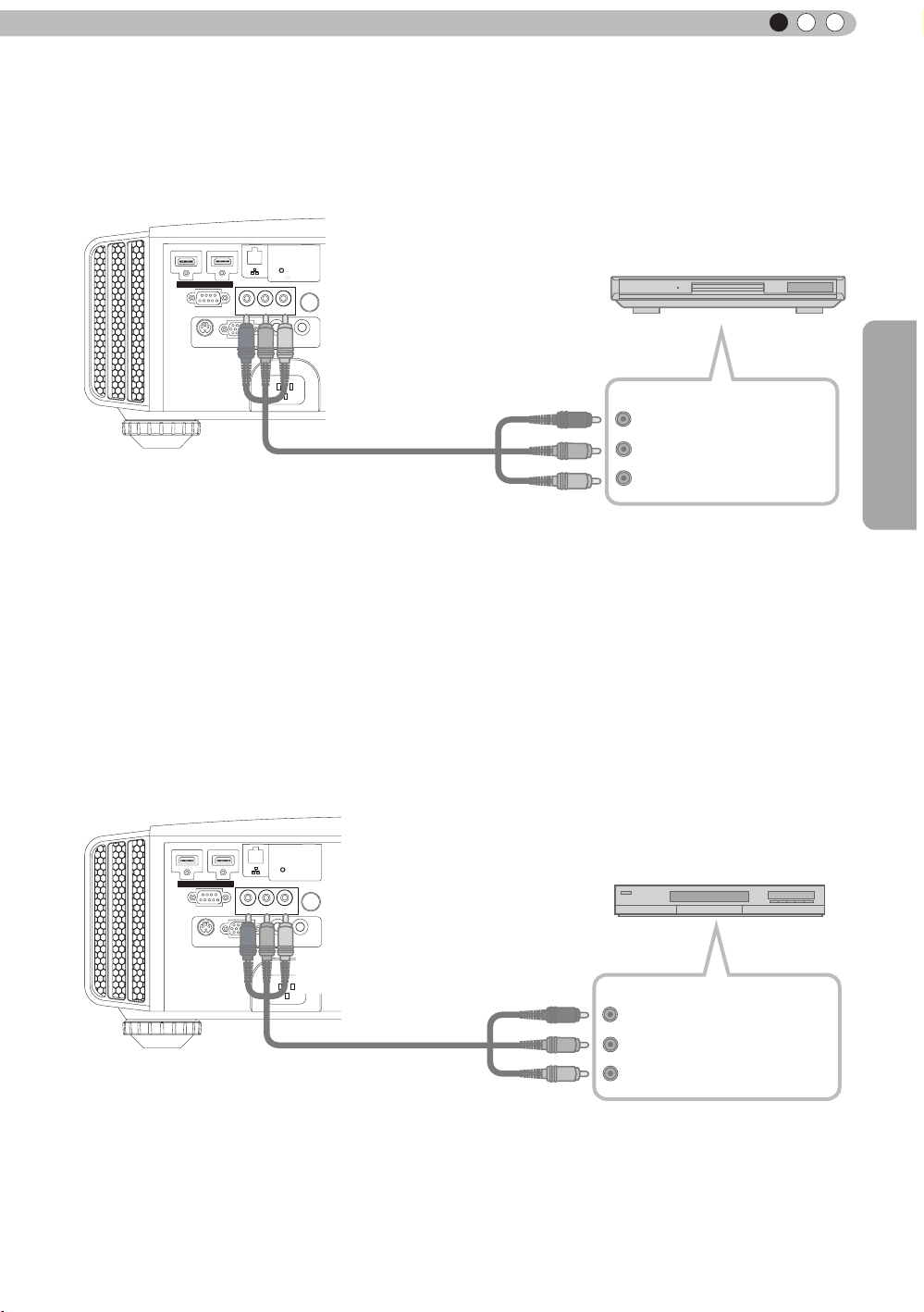
Connecting via Component Video Cable
■
This unit
STANDBY/ON
INPUT
OK
BD/DVD player
Component video output terminals
C
R/PR
C
B/PB
Y (green)
1 HDMI 2
RS-232-C
3D
SYNCHRO
C
R/PR CB/PB Y
PC
MENU BACK
REMOTE
TRIGGER
CONTROL
To component video input terminals
Component video cable
(sold separately)
Preparation
(red)
(blue)
●
Set “COMP.” in the setting menu to “Y Pb/Cb Pr/Cr”.
■
Connecting via RGB Video Cable
(Reference page: 49)
This unit
STANDBY/ON
1 HDMI 2
RS-232-C
3D
SYNCHRO
C
R/PR CB/PB Y
PC
REMOTE
TRIGGER
CONTROL
To RGB video input terminals
INPUT
OK
MENU
BACK
RGB video cable
(sold separately)
●
Set “COMP.” in the setting menu to “RGB”. (Reference page: 49)
●
For information on compatible input signals, see “Specications”.(Reference page: 76)
Device equipped with
RGB video output terminals
R(Red)
B(Blue)
G(Green)
signals)
RGB output
(Includes sync
25
Page 26
2
1 HDMI 2
RS-232-C
3D
C
R/PRCB/PB
Y
SYNCHRO
PC
TRIGGER
REMOTE
CONTROL
STANDBY/ON
MENU
BACK
INPUT
OK
1 HDMI 2
RS-232-C
3D
C
R/PRCB/PB
Y
SYNCHRO
PC
TRIGGER
REMOTE
CONTROL
STANDBY/ON
MENU
BACK
INPUT
OK
Preparation
About the connection (Continued)
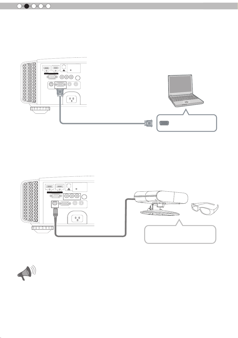
■
Connecting via PC Cable
This unit
Notebook PC
To PC input terminal
PC cable(sold separately
●
For information on supported input signals, please refer to “Specications
)
VGA output terminal
(Reference page: 76)
”.
■
Connected by a 3D SYNCHRO terminal
This unit
3D-glasses
3D synchro emitter
●
3D synchro emitter: This is a dedicated terminal for PK-EM1 (sold separately).
●
3D glasses (PK-AG1) is an optional device, and is not included in the 3D synchro emitter.
Note that converting 2D images to 3D ones using the 3D feature of this product, and playing them for
●
commercial purposes or for broadcasting in public places may infringe the rights of authors protected
under the copyright laws.
3D images may appear different depending on the ambient temperature and lamp usage. Stop using the
●
CAUTION
projector if images cannot be projected correctly.
Before you watch 3D video images, make sure to read "3D description of the system"
●
(Reference page 54 to 56).
26
Page 27
ENGLISH
1 HDMI 2
RS-232-C
3D
C
R/PRCB/PB
Y
SYNCHRO
PC
TRIGGER
REMOTE
CONTROL
STANDBY/ON
MENU
BACK
INPUT
OK
1 HDMI 2
3D
C
R/PRCB/PB
Y
SYNCHRO
PC
TRIGGER
REMOTE
CONTROL
STANDBY/ON
MENU
BACK
INPUT
OK
About the connection (Continued)
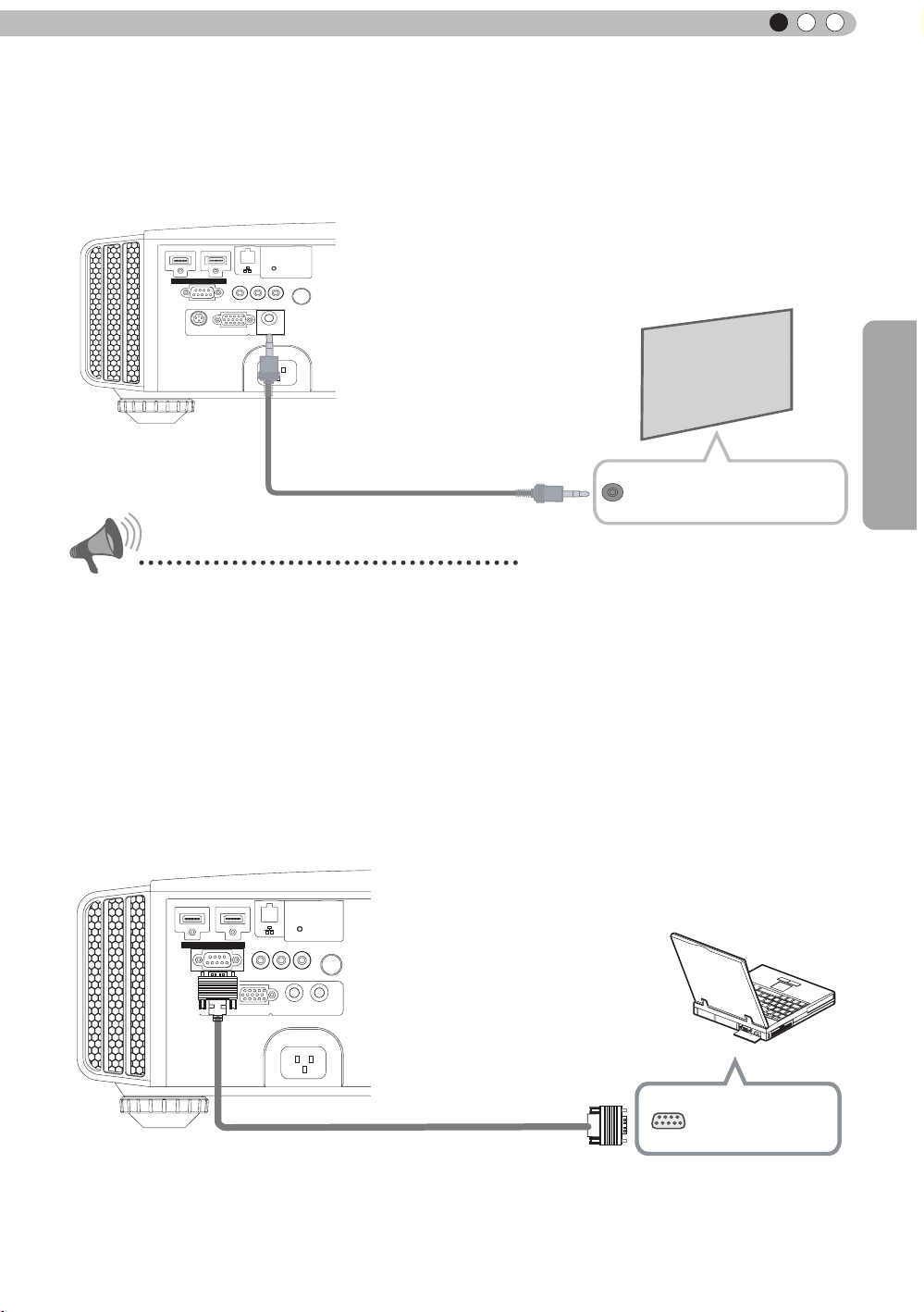
■
Connecting via Trigger Cable
This unit
Screen
To Trigger output terminal
Trigger cable
(sold separately)
CAUTION
Trigger input terminal
(Φ3.5)
Preparation
●
Do not supply the power to the other devices.
●
Do not connect audio terminals of the other devices such as headphones etc. Otherwise, this may
cause a malfunction of the other devices or injury.
●
Using beyond the rated value will cause malfunction.
● Exercise adequate caution to prevent short circuit as the trigger terminal outputs a voltage of 12V.
●
The default is set to "No output". Please set it under the item "Trigger" of menu [5] "Function" (Reference
page: 51).
■
Connected by RS-232C connection cable
This unit
RS-232C connection cable (sold separately)
RS-232C
terminal
27
Page 28
2
1 HDMI 2
RS-232-C
3D
C
R/PR CB/PB Y
SYNCHRO
PC
TRIGGER
REMOTE
CONTROL
STANDBY/ON
MENU
BACK
INPUT
OK
Preparation
About the connection (Continued)
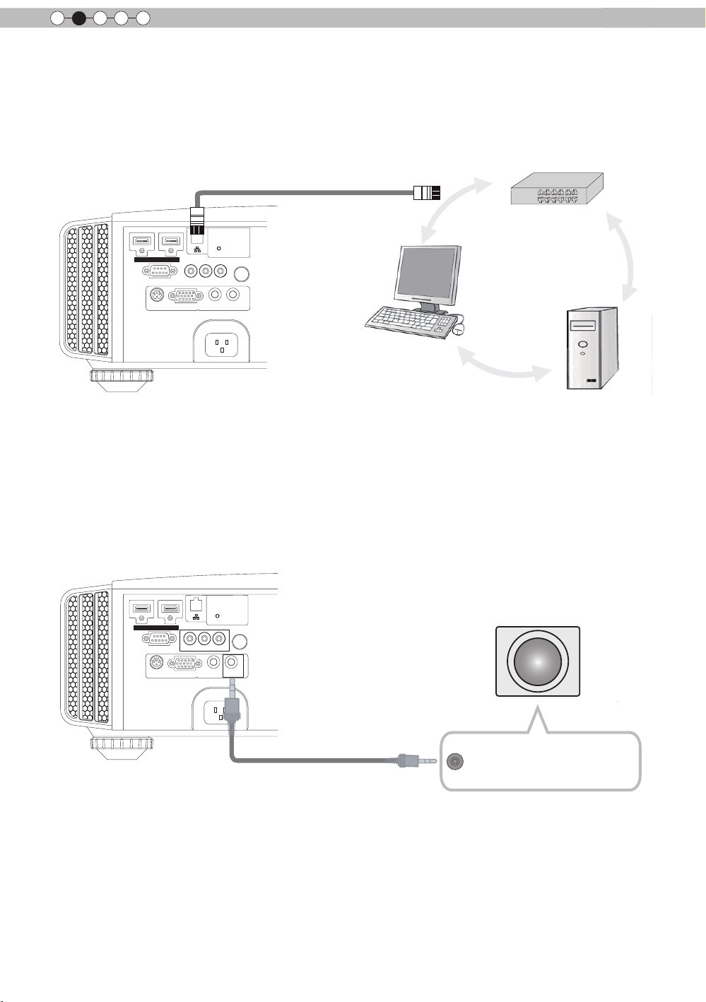
■
Connected by LAN terminal
This unit
HUB
connection cable
(sold separately)
STANDBY/ON
1 HDMI 2
C
R/PR CB/PB Y
RS-232-C
3D
PC
SYNCHRO
●
The network is used to control the unit. It is not used for transmission of the video signal.
●
Please contact your network administrator for questions concerning the network connection.
TRIGGER
REMOTE
CONTROL
INPUT
OK
MENU
BACK
Network
Server
■
Connected by a REMOTE terminal
This unit
External infrared sensor
connection cable(sold separately)
●
For an external infrared sensor and connecting cable, please contact your dealer or a JVC service
center.
(sold separately)
28
Page 29
ENGLISH
1 HDMI 2
RS-232-C
3D
C
R/PRCB/PB
Y
SYNCHRO
PC
TRIGGER
REMOTE
CONTROL
STANDBY/ON
MENU
BACK
INPUT
OK
Power Cord
(Supplied)
About the connection (Continued)
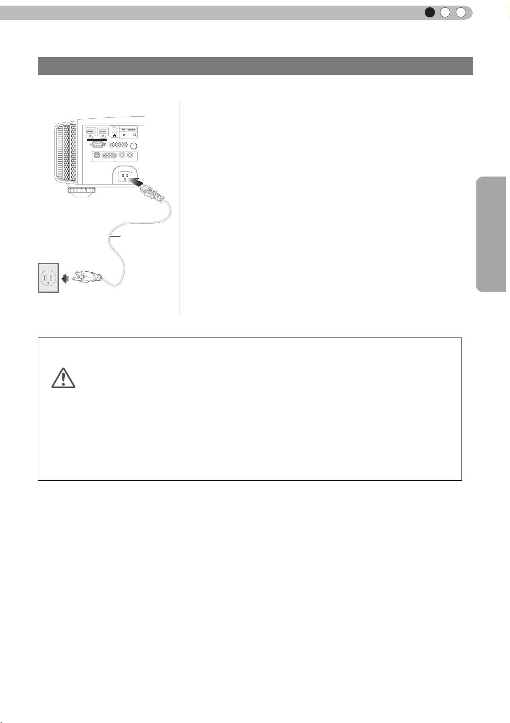
Connection of the power cord (provided)
Once you have connected the equipment, connect the projector power cord.
1 Connect the power cord supplied with the
unit power input terminal
2 Connect to the power outlet
1
2
Be carful to avoid re and electric shocks
● As the amount of electrical energy for this unit is large, please connect it directly into
the wall outlet.
CAUTION
● When you are not using the equipment, please unplug the power cord.
● Connect it only with the provided power cord.
● Do not use voltage other than the indicated power voltage.
● Do not damage, break or modify the power cord. Moreover, the power cord will be
damaged if you place it under heavy objects, heat or pull it.
● Do not unplug with wet hands.
Preparation
29
Page 30
3
INPUT
LENS
LENS
BACK
HIDE
LIGHT
C.M.D
PC
HDMI 1
STAND BY
ASPECT
HDMI 2
ANAMO
COMP
.
LENS.
CONTROL
MENU
GAMMA
AP
LENS.
ADJ.
PIC.
ON
NATURAL
3D
USER4
USER5 USER6
PICTURE MODE
COMPONENT
TEMP
COLOR
AUTO
ALIGNMENT
DYNAMIC
USER1
USER2
USER3
Operation
Basic Operation
Basic operation procedures
6
1
2
3
4
5
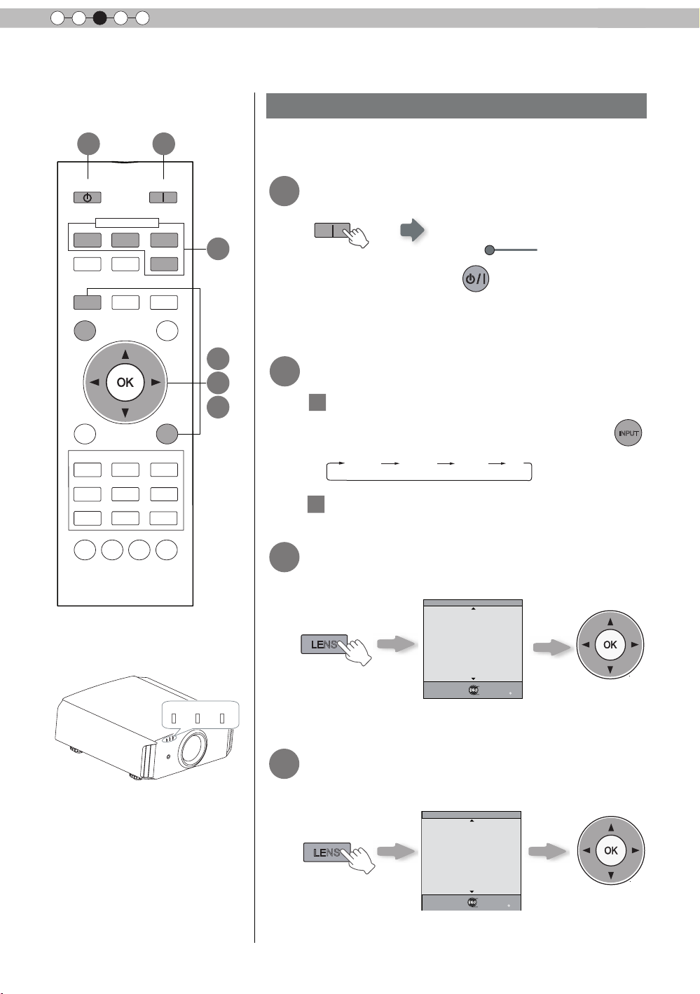
Once you have nished the basic setup, the unit can normally be
used just with the following operations.
Turn on power source
1
ON
STANDBY/ON
Light on (Green)
●
You can also press the
on the power
●
The lens cover will be opened.
Choose the projected image
2
1
Select input mode
●
You can also select the input mode by pressing the
. (Reference page: 13)
button on the unit to turn
button on the unit. (Reference page: 13)
HDMI 1
Play back the selected device
2
HDMI 2 COMP. PC
STANDBY/ON
LAMP
WARNING
30
Adjust the zoom (screen size)
3
Lens Control
Zoom
Select
Back
Exit
MENU
Operate
Adjust the focus (focal point)
4
Lens Control
Focus
Select
Back
Exit
MENU
Operate
Adjust accordingly
BACK
by pressing the up/
down buttons
Adjust accordingly
BACK
by pressing the up/
down buttons
Page 31

Adjust the shift (image position)
OK
)RFXV =RRP
6KLIW
LENS
LENS
5
Lens Control
ENGLISH
Shift
●
After adjusting the image position, it may be necessary to
select “Pixel Adjust” from the Settings menu “Installation”.
(Reference page:50)
●
Every time the
LENS
button is pressed, the adjustment
item will be switched among “Focus”, “Zoom” and “Shift”.
Turn off power source
6
It can also be switched with the button.
STAND BY
While a confirmation screen is displayed
STAND BY
Select
Operate
Back
Adjust accordingly
BACK
by pressing the
up/down/left/right
buttons
MEMO
About Cool Down
mode
●
The Cool Down mode is a
function to cool down the lamp
for approximately 60 seconds
after projection is complete.
This function prevents the
internal parts of the unit from
deformation or damage due to
overheating of the lamp. It also
prevents lamp blowout and
premature shortening of lamp
life.
●
During Cool Down mode, the
[STANDBY/ON] indicator blinks
in red.
●
After the Cool Down mode is
complete, the unit automatically
returns to standby mode.
●
Do not pull out the power plug
during Cool Down mode. This
may shorten the lamp life and
cause a malfunction.
Operation
STAND BY/ON
Blinking (Red Lamp)
Cool Down mode
STAND BY/ON
Light on (Red Lamp)
●
When power off, the lens cover will be closed.
●
The power cannot be turned off within approximately 90
seconds after it has been turned on. Start operation only
after 90 seconds time.
●
You can also press the
the power. (
●
Pull out the power plug when the unit will not be used for a
Reference page: 13
prolonged time.
button on the unit to turn off
)
31
Page 32

3
4:3 16:9 Zoom
Operation
Basic Operation (continued)
Frequently used useful functions
You can change the screen size of the projected image or
hide the surrounding area of an image for which quality at the
outer area has deteriorated.
A
Setting the Screen Size
B
Masking the Surrounding Area of an Image
C
Temporary turning-off of the video
Adjustment of the keystone correction
D
A
Setting the Screen Size
The projected image can be set to a most appropriate screen
size (aspect ratio).
ASPECT
COMPONENT
HDMI 2
ANAMO
C.M.D
ON
COMP.
PC
AUTO
ALIGNMENT
LIGHT
STAND BY
HDMI 1
A
ASPECT
LENS.
CONTROL
HIDE
MENU
NATURAL
USER1
USER4
GAMMA
PICTURE MODE
DYNAMIC
USER2
USER5 USER6
COLOR
LENS.
TEMP
AP
BACK
3D
USER3
PIC.
ADJ.
● The screen size can also be set from
“
Aspect(Video)” of the
setting menu. (Reference page: 47)
● When PC signals are input, the
“
Aspect(Computer)” setting will be
available instead. (Reference page: 47)
■
Input Image and Projected Image by Different Screen
Size
Input Image
SDTV(4:3)
SDTV(4:3)
Image recorded in
landscape (black
bands on top and
bottom) of DVD
software
● Depending on the input image, selecting
4:3
Aspect Ratio:Same
Most appropriate
screen size
Aspect Ratio:Same
Small image is
projected
vertically stretched image, while selecting “16:9” provides you
with the most appropriate screen size.
● When there is 3D signal input, the ratio is xed to
Screen Size
16:9
Aspect Ratio:
Landscape
Image is stretched
horizontally
Aspect Ratio:
Landscape
Image is stretched
horizontally
“
4:3” may result in a
Zoom
Aspect Ratio:Same
Top and bottom of
the image are
missing
Aspect Ratio:Same
Most appropriate
screen size
“
16:9”.
32
Page 33
MEMO
Exit
MENU
BACK
Back
Select
Operate
Aspect (Video)
Progressive
HDMI
COMP.
Auto
PC
Picture Position
16:9
Off
Mask
2.5%
5%
Off
Custom
Input Signal
Exit
MENU
BACK
Back
Select
Operate
Aspect (Video)
Progressive
HDMI
COMP.
Auto
PC
Picture Position
16:9
5%
5%
Mask
2.5%
5%
Off
Custom
Input Signal
MENU
●
Mask ing is av aila b le onl y
when high definition images
are input.
COMPONENT
HDMI 2
ANAMO
C.M.D
ON
COMP.
PC
AUTO
ALIGNMENT
LIGHT
STAND BY
HDMI 1
ASPECT
LENS.
CONTROL
HIDE
B
ENGLISH
B
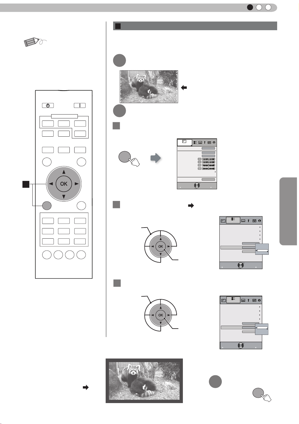
Masking the Surrounding Area of an Image
Images for which quality at the outer area has deteriorated
can be projected by masking (hiding) the surrounding area of
the projected image.
Project the image
1
Image for which quality at the outer
area has deteriorated.
Mask the image
2
1
Display the setting menu
Picture Adjust
MENU
Picture Mode
Color Temp.
Gamma
Contrast
Brightness
Color
Tint
Advanced
Exit
MENU
Select
0
0
0
0
Operate
Natural
6500K
Normal
Reset
Back
BACK
Operation
MENU
PICTURE MODE
DYNAMIC
NATURAL
USER1
USER4
COLOR
GAMMA
TEMP
Example:
When the “Mask” value is
changed from “Off”
BACK
3D
USER3
USER2
USER5 USER6
PIC.
LENS.
ADJ.
AP
“5%”
2
Select “Input Signal” “Mask
① Select
② Confirm
3
Set a mask value
① Select
② Confirm
”
3
To end
33
Page 34

3
MENU
Operation
Basic Operation (continued)
C
Temporary turning-off of the video
You can hide the image temporarily.
STAND BY
ON
HIDE
Green light blinks
when the image is
hidden.
HDMI 1
ASPECT
COMPONENT
HDMI 2
ANAMO
COMP.
PC
●
Press the
●
The power cannot be turned off when the image is temporarily
HIDE
button again to display image.
hidden.
LENS.
CONTROL
C
HIDE
D
MENU
PICTURE MODE
NATURAL
USER1
USER4
COLOR
GAMMA
TEMP
AUTO
C.M.D
ALIGNMENT
BACK
DYNAMIC
USER3
USER2
USER5 USER6
LENS.
AP
LIGHT
3D
PIC.
ADJ.
D
Adjustment of the keystone correction
In regards to the projection plane, any occurring keystone distortion
is adjusted in case the installation location is inclined.
1
Display the setting menu
Picture Adjust
Picture Mode
Color Temp.
MENU
2
Select “Installation” “Keystone
Gamma
Contrast
Brightness
Color
Tint
Advanced
Exit
MENU
Select
① Selec
0
0
0
0
Operate
Natural
6500K
Normal
Reset
Back
BACK
Lens Control
Pixel Adjust
Installation Style
Keystone
Anamorphic
Black Level
”
Installation
Front
Off
●
When there is a 3D input
signal, adjustment is not
possible. Moreover, even if
the keystone correction is
adjusted, keystone correction
is removed when there is a 3D
input signal.
34
② Confirm
3
Adjusts keystone correction
Exit
MENU
Select
Operate
Back
BACK
If one presses the cursor (vertical and horizontal arrows) in the
keystone correction mode, the keystone distortion can be adjusted.
Adjust horizontal distortion with the
cursors for left and right.
Adjust vertical
distortion with
the cursors for
up and down.
Exit
4
Page 35

ENGLISH
Picture Adjust
Reset
Exit
MENU
BACK
Back
Select
Operate
Picture Mode
Natural
Color Temp.
Gamma
Contrast
Brightness
Color
Tint
Advanced
0
0
0
0
6500K
Normal
Exit
MENU
BACK
Back
Select
Operate
Aspect(Video)
Progressive
HDMI
COMP.
Mask
Auto
PC
Picture Position
16:9
Off
Input Signal
Adjustments and settings in the menu
Structure of the menu hierarchy (summary)
The Menu of this unit is organized as follows. As this is only a brief guideline, items, which might not be
displayed due to certain settings, are still displayed in the illustration. See “Description of menu items”
(Reference: Since 43 and following) for details. It can be moved to subscreens used for adjustment, even
for items that do not feature submenus.
[1] Picture Adjust
[2] Input Signal
(*)
Operation
(*) When there is a PC
signal input, “Aspect
(PC)” is displayed.
Continue to
the next
To “[1] Layers and
organization of the picture
quality submenu
To “[2] Layers and
organization of the input
”
signal submenu”
35
Page 36

3
Exit
MENU
BACK
Back
Select
Operate
Pixel Adjust
Installation
Lens Control
Keystone
Anamorphic
Black Level
Installation Style
Front
Off
Exit
MENU
BACK
Back
Select
Operate
Display Setup
Back Color
Menu Display
On
Line Display
5sec
Source Display
On
Lamp Replacement Display
Off
Logo
On
Language
English
Black
Menu Position
Operation
Adjustments and settings in the menu (continued)
[4] Display Setup[3] Installation
Continued from
the previous page
Continue
to the next
To “[3] Layers and
organization of the
installation submenu”
36
Page 37

ENGLISH
Exit
MENU
BACK
Back
Select
Operate
Trigger
Off Timer
Communication Terminal
Network
Lamp Reset
High Altitude Mode
LAN
Off
Off
Off
Function
Exit
MENU
BACK
Back
Select
Operate
160H
HDMI-2
1080p60
10bit
Input
Source
Deep Color
Lamp Time
Information
:
:
:
:
Exit
MENU
BACK
Back
Select
Operate
Lamp Time
Deep Color
160H
PC
1920X1080
Information
Resolution
67.50kHz
H Frequency
60.0Hz
V Frequency
Input
:
:
:
:
:
:
8bit
Adjustments and settings in the menu (continued)
[6] Information[5] Function
Continued
from the
previous
page
Operation
To “[5] Layers and
organization of the function
submenu”
For PC signal input
37
Page 38

3
Color Management
Color Selection
Axis Position
Hue
Saturation
Brightness
Off
Custom1
Custom2
Custom3
Picture Adjust
Exit
MENU
BACK
Back
Select
Operate
0
0
0
0
Pause
Off
Reset
Red
>
>
Exit
MENU
BACK
Back
Select
Operate
0
>
>
25
Detail Enhance
Sharpness
Picture Adjust
Sharpness
Custom Gamma
Correction Value
White
Red
Green
Blue
Reset
1023
512
50
100(%)
Custom1
Custom2
Custom3
0
Picture Adjust
Exit
MENU
BACK
Back
Select
Operate
Normal
>
>
Picture Adjust
Reset
Exit
MENU
BACK
Back
Select
Operate
Picture Mode
Natural
Color Temp.
Gamma
Contrast
Brightness
Color
Tint
Advanced
0
0
0
0
6500K
Normal
>
Color Temp.
Gain Red
Gain Green
Gain Blue
Offset Red
Offset Green
Offset Blue
5500K
6500K
9500K
High Bright
Custom1
Custom2
Custom3
Picture Adjust
Exit
MENU
BACK
Back
Select
Operate
Reset
0
0
0
0
0
0
Picture Adjust
Exit
MENU
BACK
Back
Select
Operate
>
Advanced
0
Lens Aperture
CMD Demo
Clear Motion Drive
Color Management
Custom Gamma
NR
Lamp Power
Sharpness
Off
Off
Normal
Operation
Adjustments and settings in the menu (continued)
[1] Layers and organization of the picture adjust submenu
[1] Picture Adjust
[1-1]
[1-2]
[1-2-1]
[1-2-2]
[1-2-3]
[1-1] Color temp.
[1-2-1] Sharpness
[1-2] Advanced
[1-2-2] Custom Gamma
38
[1-2-3] Color Management
Page 39

ENGLISH
Exit
MENU
BACK
Back
Select
Operate
Input Signal
COMP.
Y Pb/Cb Pr/Cr
Color Space
Exit
MENU
BACK
Back
Select
Operate
Level Check
Input Signal
HDMI
Off
Control with HDMI
Auto
Color Space
Auto
3D Format
Enhanced
Input
Exit
MENU
BACK
Back
Select
Operate
Input Signal
PC
16
Phase
2200
Tracking
Picture Position
Auto Alignment
Exit
MENU
BACK
Back
Select
Operate
Aspect(Video)
Progressive
HDMI
COMP.
Mask
Auto
PC
Picture Position
16:9
Off
Input Signal
Adjustments and settings in the menu (continued)
[2] Layers and organization of the input signal submenu
[2-1] HDMI
[2] Input Signal
[2-1]
[2-2]
[2-3]
[2-2] COMP.
Operation
[2-3] PC
39
Page 40

3
Exit
MENU
BACK
Back
Select
Operate
Trigger
Off Timer
Communication Terminal
Network
Lamp Reset
High Altitude Mode
LAN
Off
Off
Off
Function
Exit
MENU
BACK
Back
Select
Operate
IP Address
Subnet Mask
Default Gateway
Network
DHCP Client
Off
Function
Set
MAC Address :
AA-BB-CC-DD-EE-FF
192. 168. 0.254
255. 255. 255. 0
192. 168. 0. 2
Exit
MENU
BACK
Back
Select
Operate
Pixel Adjust
Installation
Lens Control
Keystone
Anamorphic
Black Level
Installation Style
Front
Off
Exit
MENU
BACK
Back
Select
Operate
Lock
Off
Zoom
Shift
On
Image Pattern
Auto
Lens Cover
Installation
Lens Control
Focus
Exit
MENU
BACK
Back
Select
Operate
Horiz. Green
Horiz. Blue
Installation
Pixel Adjust
Vert. Red
Vert. Green
Vert. Blue
3
3
3
3
3
Horiz. Red
3
Operation
Adjustments and settings in the menu (continued)
Layers and organization of the submenus [3] installation and [5] function
[3-1] Lens Control
[3] Installation
[3-1]
[3-2]
[3-2] Pixel Adjust
[5] Function
[5-1]
40
[5-1] Network
(*)
(*) MAC address is different
depending on the
respective equipment
Page 41

ENGLISH
STANDBY/ON
MENU
BACK
INPUT
OK
Adjustments and settings in the menu (continued)
Menu operation button
Operate the menu by use of the buttons on the main body or the
remote control.
Button
This unit Remote Control
MENU
OK OK
BACK
This unit
Remote Control
MENU
BACK
Function
Menu is displayed.
While t he menu is displa yed,
the men u screen is turne d off.
While showing "Main menu" (Layer 1)
selected items are confirmed, and
"Submenu" (Layer 2) will be displayed.
When the submenu is displayed, press
OK, and the displayed items in the
selection are moved to the
"Setting screen" (Layer 3).
Return to the previous menu screen.
The menu screen is turned off when
the main menu screen is shown.
Displaying the main menu and the
submenu
Select an adjustment item in the
:/
menu. Set the setting value of the
selected adjustment item. The
adjusted setting value is immediately
reflected in the image.
:
/
Selection of a displayed sub-menu
item. Selection of an item in the
menu.
STAND BY
HDMI 1
ASPECT
LENS.
CONTROL
HIDE
MENU
NATURAL
USER1
USER4
GAMMA
COMPONENT
HDMI 2
ANAMO
C.M.D
PICTURE MODE
DYNAMIC
USER2
USER5 USER6
COLOR
LENS.
TEMP
AP
ON
COMP.
PC
AUTO
ALIGNMENT
USER3
LIGHT
BACK
3D
PIC.
ADJ.
Menu
operation
buttons
Menu
operation
buttons
Operation
41
Page 42

3
STANDBY/ON
MENU
BACK
INPUT
OK
Exit
MENU
BACK
Back
Select
Operate
160H
HDMI-2
1080p60
10bit
Input
Source
Deep Color
Lamp Time
Information
:
:
:
:
Exit
MENU
BACK
Back
Select
Operate
Lamp Time
Deep Color
160H
PC
1920X1080
Information
Resolution
67.50kHz
H Frequency
60.0Hz
V Frequency
Input
:
:
:
:
:
:
8bit
Operation
Adjustments and settings in the menu (continued)
Menu operation procedure
1 Press MENU.
The main menu is displayed on the screen.
The submenu items, which are currently
selected, are shown. Currently selected menu
Natural
items are highlighted and the icon is colored
6500K
Normal
in orange.
The submenu items, which are currently
selected, are displayed.
Reset
Back
BACK
1
STAND BY
ON
3
3,4
2,5
6
Picture Adjust
Picture Mode
Color Temp.
Gamma
Contrast
Brightness
Color
Tint
Advanced
Exit
0
0
0
0
Select
Operate
MENU
Example: Picture Adjust
2 Press cursor ( / ) to select a submenu.
● A submenu (picture adjust, input signal, installation, display
setup, function, information) is selected:
● If one selects "Information", information about the currently
selected video input and PC input are displayed at the bottom
of the menu.
3 Press OK or cursor ( / ).
● Sub-menu item is displayed.
● Sub-menu items vary depending on the input signal and the
picture mode. See "Content menu" on the next page for more
details.
1
HDMI 1
ASPECT
LENS.
CONTROL
HIDE
MENU
NATURAL
USER1
USER4
GAMMA
COMPONENT
HDMI 2
ANAMO
C.M.D
PICTURE MODE
DYNAMIC
USER2
USER5 USER6
COLOR
LENS.
TEMP
AP
COMP.
PC
AUTO
ALIGNMENT
LIGHT
BACK
3D
USER3
PIC.
ADJ.
3,4
2,5
3
6
Example: Input of signals
other than PC signals
Example: When inputting
PC signals
4 Press the cursor ( / ) to select the items to
adjust.
If the name of a submenu item is displayed in a dimmed manner,
it cannot be selected.
5 Press cursor ( / ) to change settings.
6 After adjusting, press BACK.
Every time it is pressed, you will return to the respective previous
menu screen.
7 Repeat steps 6-2 to adjust other items.
After all adjustments are done, press MENU, and the menu
disappears from the screen.
42
Page 43

ENGLISH
Adjustments and settings in the menu (continued)
Menu item description
All numbers for the items within [ ]are default settings.
● It is possible to operate all items displayed in the menu display by pressing OK/BACK or the cursor (up,
down, left, right arrows).
● Displayed items vary depending on the selected item in the menu and type of input signal or absence of
any signal.
[1] Picture Adjust
Picture Mode
Natural It is an image quality setting with natural color/tone. Suitable for viewing video material,
Dynamic This is the picture setting best suited for viewing the picture in a room that cannot be
3D This is an image quality setting for watching 3D movies.
User 1
User 2
User 3
User 4
User 5
User 6
Color Temp.
Gamma
Normal Typically we recommend this setting.
A (3D)
B (3D)
A
B
C
D
Custom 1
Custom 2
Custom 3
Contrast
Brightness
Color
Tint
Advanced
Reset
Please refer to the description of each mode, and then use the mode to best suited for
you. Moreover, it is possible to adjust the image quality by using a user 1, 2, 3, 4, 5and 6.
Settings: Natural, Dynamic, 3D, User 1, User 2, User 3, User 4, User 5, User 6.
[Natural]
such as dramas/serials.
made completely dark.
The users 1, 2, 3, 4, 5, and 6 should adjust the image quality as desired in each case.
Data of the last adjustment is saved.
It is possible to set the color temp.
To "[1-1] Color Temp." of the submenu
It is possible to set the gamma curve. Please set to your preference.
Settings: Normal, A (3D), B (3D), A, B, C, D, Custom 1, Custom 2, Custom 3
[Normal]
(*) It is not possible to set it when the "Picture Mode" is set to "3D".
A (3D), B (3D) can only be set, if the "Picture Mode" is "3D".
This is the normal gamma curve for 3D.
A (3D) will be brighter.
A, B, C, D cannot be set if the "Picture Mode" is "3D".
In regard to normal gamma, this is a gamma curve focused on tone.
This is a gamma curve for the lm's unique S curve.
This is a gamma curve that – in regard to the gamma of B – emphasized even more the
feeling of contrast.
For normal, this is a gamma curve where the intermediate gradations look very bright.
Custom 1, 2, 3 cannot be set if the "Picture Mode" is "3D".
Under submenu "[1-2-2] Custom Gamma", it is possible to change the gamma curve and
save it.
The initial value of Custom 1, 2, and 3 is the same as for "Normal".
Adjusts the contrast of the video images.
Settings: (blackish) -50 to 50 (whitish)
You can adjust the brightness of the video image.
Settings: (dark) -50 to 50 (bright)
Adjust the color intensity of the video images.
Settings: (dim), -50 to 50 (saturated)
Adjusts the image tint of the video images.
Settings: (reddish) -50 to 50 (greenish)
Functions such as contour correction, custom gamma and color management can be set
to sub-menu "[1-2] Advanced".
Sets settings to default factory settings.
Operation
43
Page 44

3
Operation
Adjustments and settings in the menu (continued)
[1-1] Color Temp.
Set the color temp. of the video images.
Please adjust to your preference.
(*) For this setting, the setting items can differ in accordance with the "Picture Mode".
Settings: (Preset value), High Bright, Custom 1, Custom 2, Custom 3
[Preset value]
(Preset value) You can set the Color Temp. to 5500K, 6500K or 9500K.
High Bright Select this to get the brightest image.
Custom 1
Custom 2
Custom 3
Gain It is possible to adjust the bright part of the video images for each color.
Red Settings: (Weak red) -255 to 0 (strong red) [0]
Green Setting: (Weak green) -255 to 0 (strong green) [0]
Blue Setting: (Weak blue) -255 to 0 (strong blue) [0]
Offset
Red
Green
Blue
It is said that a value of 6500K produces a well balanced video image.
Settings: (reddish) 5500, 6500, 9500 (bluish) [6500]
(*) It is not possible to set it when the "Picture Mode" is set to "3D" or "Natural".
You can adjust the color temp. and save each Custom 1, 2, and 3.Please save your
preferred adjustment values and enjoy it.
For each color, the dark areas of the video images can be adjusted.
Settings: (Weak red) -50 to 50 (strong red) [0]
Setting: (Weak green) -50 to 50 (strong green) [0]
Setting: (Weak blue) -50 to 50 (strong blue) [0]
[1-2] Advanced
Sharpness
NR
RNR Adjusts the intensity of random noise elimination of the image.
MNR Adjusts the intensity of mosquito noise elimination of the video images.
BNR Reduces the block noise of the video images.
Custom Gamma
You can set the sharpness and detail enhance to "[1-2-1] Sharpness" of the submenu
Reduces the noise of the video images. Please adjust to your preference.
Values: (Low) 0 to16 (strong) [0]
(*) It is not possible to set it when the "Picture Mode" is set to "3D".
Moreover, it is not possible to set it when there is an input of HD input signals.
Values: (Low) 0 to16 (strong) [0]
(*) ) It is not possible to set it when the "Picture Mode" is set to "3D"
Moreover, it is not possible to set it when there is an input of HD input signals.
Settings: On, Off [Off]
It is possible to set the gamma curve and save it. Please adjust to your preference.
To "[1-2-2] Custom Gamma" of the submenu
44
Page 45

ENGLISH
Adjustments and settings in the menu (continued)
Color Management
Clear Motion Drive
Off Off
Mode 1 Black insertion weak
Mode 2 Black interpolation strong
Mode 3 Interpolation weak
Mode 4 Interpolation strong
Inverse Telecine With 60i/60p signals, e.g of TV-broadcast and DVDs, original 24 frame video image
CMD Demo
Left The left screen displays a demonstration of the Clear motion drive.
Right The right screen displays a demonstration of the Clear motion drive.
Top The upper screen displays a demo of the Clear motion drive.
Bottom The screen below displays a demo of the Clear motion drive.
Off The Demo of the Clear motion drive is turned off.
Lens Aperture
Lamp Power
Normal Normally this setting is chosen.(160W drive)
High In a bright room, when the video is hard to see, this setting is chosen.(220W drive)
It is possible to set the color of the screen to the preferred color and save it.
To "[1-2-3] Color Management" of the submenu.
It improves video images with fast movements to produce clear video images with little
residual image retention.
For PC and 3D signals, the "Clear motion Drive” cannot be set.
Moreover, it may happen that the image is distorted in some scenes, or light and dark
ashes occur. In this case, please choose "Off", etc., and then a setting of your choice.
Settings: Off, Mode 1, Mode 2, Mode 3, Mode 4, Inverse Telecine [Off]
footage is changed to a 24 frame display.
(*) 24p will not function.
It is possible to conrm the effect of the setting of Mode 3 and Mode 4 of the Clear motion
drive. Upon pressing the button "OK", it will be displayed on all sides of a screen in the
center split into two parts. Finally, it will turn to "Off”. It cannot be set for PC and 3D
signals.
Settings: Left -> right -> top -> Bottom -> Off (changed with "OK" button) [Off]
Adjusts the amount with which the optical iris is squeezed. A setting of 0 means fully
opened.
Settings: (Dark) -15 to 0 (bright) [0]
It is possible to change the brightness of the lamp.
(*) If continually used with "High", the lamp will become dark earlier.
(*) The more one lets the interior temperature of the device rise due to generation of heat,
the less the level of tolerance against high temperatures.
(*) For about 60 seconds after the lamp is lit, the lamp cannot be switched off.
Settings: Normal, High [Normal]
Operation
[1-2-1] Sharpness
Sharpness
Detail Enhance
Emphasizes the outlines of video images. Please adjust to your preference.
Values: 0 to 50 (clear)
It makes minute details of the video images stand out. Please adjust to your preference.
Values: 0 to 50 (strong)
45
Page 46

3
Custom Gamma
Correction Value
White
Red
Green
Blue
Reset
1023
512
50
100(%)
Custom1
Custom2
Custom3
0
Picture Adjust
Exit
MENU
BACK
Back
Select
Operate
Normal
>
>
Operation
Adjustments and settings in the menu (continued)
[1-2-2] Custom Gamma
Custom 1~3
Correction Value You can choose to add the underlying gamma curve adjustment.
Gamma Adjustment The gamma curve for "green" is being displayed as being representative. If "white", "red,"
White Red, green and blue can be adjusted at the same time.
Red It is possible to adjust the gamma curve of red.
Green It is possible to adjust the gamma curve for green.
Blue It is possible to adjust the gamma curve for blue.
Reset The same data as for the "Normal" mode are used.
(*)
[1] It is possible to select a gamma curve adjustment for Custom 1, 2, and 3 under the
"Gamma" of the picture adjust and then save it.
Please adjust to your preference.
(*) Initial values of Custom 1, 2, and 3 are the same as for "Normal".
(*) Please refer to the gure at the bottom of the menu in two frames for adjustment.
(*) It is recommended that you read "Gamma Curve" (page reference: 53) for hints about
adjustment.
(*) Can choose any setting, as the default gamma curve will always appear linear.
Settings: Normal, A, B, C, D
(brightens in particular dark to intermediate parts) 1.8 to 2.6 (darkens in particular dark to
intermediate parts) in the range of values with increments of 0.1 [Normal]
"green" or "blue" are selected, the corresponding color curves are displayed.
Place the cursor on a gamma curve with 12 points with the buttons for left and right, and
then use the buttons for up and down buttons to move those points up or down.
(*) When you exit the adjustment menu of Custom Gamma, please save the adjustment
values.
You can return to the original data, which should be saved.
Gradation at the
selected point.
46
Gamma curve
Gradation diagram
corresponding
to the gamma
curve.
Page 47

ENGLISH
Adjustments and settings in the menu (continued)
[1-2-3] Color Management
Custom 1~3
Pause It is possible to display the input video image of the background being adjusted as a still
On
Off
Color Selection It is possible with the 7 colors of red, orange, yellow, green, cyan, blue and magenta to
Axis Position Fine-tune the position of the central axis of the selected color further.
Hue Adjust the hue.
Saturation Adjust the color saturation.
Brightness Adjust the brightness.
Set the 7 color axis (red / orange / yellow / green / cyan / blue / magenta) color as you
like and save it then. For example you may want to change only the red color of roses.
Please adjust to your preference. According to your adjustments, the input image in the
background changes. It is possible to conrm the video image before adjustment by
pressing the "HIDE" button of the remote control.
picture.
Settings: On, Off [Off]
Freezes the input video image.
Unfreezes the input video image.
precisely adjust the hue, color saturation and brightness, and then save it. Please adjust
to your preference.
Settings: -30 to 30 [0]
Settings: -30 to 30 [0]
Settings: (dim color), -30 to 30 (vivid colors) [0]
Settings: (dark) -30 to 30 (bright colors) [0]
[2] Input Signal
HDMI It is possible to set this if one selects the HDMI terminal to the submenu "[2-1] HDMI".
COMP. This can be set if one selects the COMP. terminal to the submenu "[2-2] COMP."
PC This can be set if one selects the PC terminal to the submenu "[2-3] PC".
Picture Position
Horiz.
Vert.
Aspect (Video)
4:3 Sets the screen size of the image to 4:3. For HD signals, left and right sides are reduced.
16:9 Sets the screen size of the video image screen to 16:9. For SD signals left and right sides
Zoom Zooms the video images. (*) For HD signals, this cannot be selected.
Aspect (PC)
Auto Positions the video image screen in the center of the display range, to ll the screen.
Just The video image screen size is displayed with the size of the input image.
Full It does not keep the aspect ratio of the video image screen and lls the entire screen.
Please adjust if the edges of the picture are partially missing due to the timing of
horizontal and vertical synchronization signals. The value of the picture position depends
on the input signal.
(*) Depending on the input signal, it may be the case that not everything of the video
image is displayed.
(*) When there is a 3D input signal, adjustment is not possible.
This aligns the horizontal direction of the image position.
This aligns the vertical positions of the image.
(*) It is displayed when there is a video signal input.
(*) If set to3D, ratio is xed to 16:9.
Settings: 4:3, 16:9, Zoom [16:9]
are expanded.
Sets the video image screen size when there is a PC video signal input.
(*) Is displayed when there is a PC signal input.
Settings: Auto, Just, Full [Auto]
Depending on the size of the video screen, left and right black borders will be drawn.
Depending on the input video image, the screen will become smaller or part of the input
image off the screen is cut off.
Operation
47
Page 48

3
Operation
Adjustments and settings in the menu (continued)
Mask
Off Not masked.
2.5% Compared to the original video images, around 2.5% around the video images are
5% Compared to the original video images, around 5% around the video images are masked.
Custom
Left Compared to the original video images, around 5% of the video images are masked on
Right Compared to the original video images, around 5% of the video images is masked on the
Top Compared to the original video images, around 5% of the video images are masked at the
Bottom Compared to the original video images, around 5% of the video images are masked at the
Progressive
Auto It is automatically detected if the 24p video images, which can be seen in the lm screens,
Off The interpolation of video images as interlaced video signals, e.g. video material is done.
It hides the upper, lower, left and right borders of the screen with a black mask. Can be
individually adjusted vertically and horizontally. Please adjust to your preference.
Setting: Off, 2.5%, 5%, Custom [Off]
masked.
the left side.
Settings: 0 ~ 48 [0]
right side.
Settings: 0 ~ 48 [0]
upper side.
Settings: 0 ~ 28 [0]
bottom side.
Settings: 0 ~ 28 [0]
Interlaced signals (480i/576i/1080i) are converted to progressive signals. Interpolates
interlaced signal video images with video images from the surrounding. Please set to your
preference.
Settings: Auto, Off [Auto]
interlaced signals from the original video material or if they are the product of signal
conversion and are interpolated accordingly.
[2-1] HDMI
Input
Standard It gets set if the dynamic image range of the gradation level of the input image is set to
Enhanced It is set if the dynamic range of the input video scale level is 0-255.If these are PC signals,
Super White It is set if the dynamic range of the input video scale level is 16-255.Please set the output
Level Check
0 235
255 16
Color Space
Auto YCbCr(4:4:4), YCbCr(4:2:2), RGB signals are automatically detected and congured.
YCbCr (4:4:4) Sets it if the input of the YCbCr(4:4:4) input video image signal is performed.
YCbCr (4:2:2) Sets it if the input of the YCbCr(4:2:2) input video image signal is performed.
RGB It is set when the RGB video signals input is performed.
Control with HDMI
(*) It can be set when the HDMI terminal is selected.
Sets the dynamic range of the input video images (scale). Dark and bright areas, which
are not matched to the range, might get brighter or darker. If you are unsure of the input
signal dynamic range, please check under "Level Check".
Settings: Standard, Enhanced, Super White [Enhanced]
16-235. In case of a video signal, please set it up here.
please set them here.
to video equipment compatible with Super White for Super White-enabled DVD / BD etc.
You can conrm the dynamic range of the input signal.A pattern as shown in the
illustration is displayed in the four corners and center of the screen. Please compare the
dynamic range of input signal with this pattern illustration and conrm.
(*) The number in the illustration is the scale level. This number is not displayed. The
illustration of the gradation in the gure is accentuated for explanatory purposes It is
different from the actual scale level.
It sets the color space of the input signal.
Settings: Auto, YCbCr(4:4:4), YCbCr(4:2:2), RGB [Auto]
Congured communication of the HDMI equipment control
Settings: On, Off [Off]
48
Page 49

ENGLISH
Adjustments and settings in the menu (continued)
3D Format
Auto Is set automatically.
Frame Packing Select this if the 3D input signal is the frame pack method.
Side by Side Select this if the 3D input signal is the side by side method.
Top and Bottom Select this if the 3D input signal is the top and down method.
2D Projected as a 2D signal.
Sets the format of the 3D input signal.
Some signals may not be appended with 3D information themselves, and projection may
fail if they are recognized as normal 2D signals.
When this occurs, congure the settings manually.
(*) It is recommended to read "On 3D" (reference page: 54) before watching 3D video
images.
Settings: Auto, Frame Packing, Side by Side, Top and Bottom, 2D [Auto]
[2-2] COMP.
(*) It can be set when the COMP. terminal is selected.
Color Space
Y Pb/Cb Pr/Cr It is set for the component video image input signal.
RGB It is set for the RGB video image input signal.
It congures the input signal method of the component input terminal.
Settings: Y Pb/Cb Pr/Cr, RGB [Y Pb/Cb Pr/Cr]
[2-3] PC
(*) Setting can be done when selecting a PC terminal.
Auto Alignment
Tracking
Phase
Picture Position
Horiz. Adjusts the horiz. of the video image.
Vert. Adjusts the vertical position of the image.
The picture position of Tracking and Phase are automatically adjusted.
Adjusts the size and display of the horizontal direction and display area of the video
images.
(Depending on the signal, there is normally no need to be adjusted.)
Adjusts the ickering and blur of the video images.
(Depending on the signal, there is normally no need to adjustment.)
Adjust the display of the picture position.
Operation
[3] Installation
Lens Control To Sub-menu "[3-1] Lens Control"
Pixel Adjust To submenu "[3-2] Pixel Adjust"
Installation Style
Front Front upright projection mode.
Ceiling Mount (F) Ceiling/front projection mode.
Rear Rear upright projection mode.
Ceiling Mount (R) Ceiling/ rear projection mode.
Keystone
Horizontal Adjusts the horizontal keystone.
Vertical Adjusts the vertical keystone.
Matching the state of the projector’s projection, one can switch horizontal and vertical ip
/ forward switch.
Settings: Front, Ceiling Mount (Front), Rear, Ceiling Mount (RE) [Front]
In regards to the projection plane, any occurring keystone distortion is adjusted in case
the installation location is inclined.
(*) There may be instances, when the video image - after having corrected keystone
distortion - will not match the screen. The position with a shift correction of 0% position is
an exception.
(*) When there is a 3D input signal, adjustment is not possible.
Settings: -40 to 40 [0]
Settings: -30 to 30 [0]
49
Page 50

3
Operation
Adjustments and settings in the menu (continued)
Anamorphic
A Video with an aspect ratio of 2.35:1 is enlarged in the vertical direction of the panel
B Video with an aspect ratio of 16:9 are displayed by reducing them in the horizontal
Off Used when watching video images other than those with a 2.35:1 aspect ratio while using
Black Level
The video images are projected after being enlarged in the vertical direction of the panel
resolution. This setting is used when one uses the anamorphic lens to enlarge them in the
horizontal direction.
(*) Anamorphic mode cannot be set when there is a 3D signal input.
If a 3D signal is fed in when Anamorphic mode is set to A or B, Anamorphic mode is
automatically turned Off.
Settings: A, B, Off [Off]
resolution and then projected.
direction, without changing their size in the vertical direction.
an anamorphic lens. 2.35:1 video images are projected without any changes. (Black
bands appear on all sides)
Sets the black level when used indoors.
Settings: 0 to 10 [0]
[3-1] Lens Control
It controls each motorized functions of the lens during the projector-installation.
Focus
Zoom
Shift
Lens Cover
Auto This opens/closes the lens cover when it is linked to on/off of a power supply.
Open Regardless if the power supply is on/off, the lens cover is always open.
Image Pattern
On During the adjustment, the image pattern is displayed.
Off The external input signal is displayed without displaying the image pattern.
Lock
On It is not possible to adjust the above setting items. If the remote control button "LENS"
Off This functions as lens control function.
This function is used to adjust the focus.
This function is used to adjust the zoom.
This function is used to adjust the shift.
This function is used to set if the lens cover should be linked with a power supply for
opening/closing, or if it should be left open.
Settings: Auto, Open [Auto]
It is possible to adjust the projection screen during adjustment of the focus zoom shift.
Settings: On, Off [On]
The image pattern is displayed in conjunction with the above setting items.
This sets the lens control to on/off.
Settings: On, Off [Off]
button is pressed, a warning message is issued.
[3-2] Pixel Adjust
This ne tunes each slight color errors in the horizontal/vertical directions of the video
images in units of 1 pixel.
(*) It is impossible to match all image pixels on the screen. Due to the equipment, there
will always be some gaps.
(*) In case the image is reversed, or upside-down, the horizontal and vertical directions
are reversed.
(*) Please perform adjustments on a clear still picture.
(*) For ne tuning, the effects of adjustments may be difcult to understand for some
video images.
Horiz. Red
Horiz. Green
Horiz. Blue
Vert. Red
Vert. Green
Vert. Blue
(Move red to the left) 1 to 5 (Move red to the right) [3]
(Move green to the left), 1 to 5 (Move red to the right) [3]
(Move blue to the left) 1 to 5 (Move red to the right) [3]
(Move red down) 1 to 5 (Move red up) [3]
(Move green down) 1 to 5 (Move green up) [3]
(Move blue down) 1 to 5 (Move blue up) [3]
50
Page 51

ENGLISH
Adjustments and settings in the menu (continued)
[4] Display Setup
Back Color
Blue Sets the background color to blue.
Black Sets the background color to black.
Menu Position
Menu Display
15 sec If there is no menu operation for 15 seconds, the menu display vanishes.
On Display always.
Line Display
5 sec Displays for 5 seconds.
Off Not displayed.
Source Display
On Display.
Off Not displayed.
Lamp Replacement
Display
On Display.
Off Not displayed.
Logo
On Displayed for 5 seconds.
Off Not displayed.
Sets the color of the background, which is displayed without an input signal.
Settings: Blue, Black [Blue]
Sets the picture position of the menu. Please set to your preferred position Navigate the
menu by pressing the left or right keys when you have selected an item. Moreover, if
one presses the button [OK], an image illustration appears at the position of the menu.
The highlighted position in the illustration moves by use of the left and right keys. If one
presses [OK], the menu moves to the highlighted position.
If you press the key to the right, the menu will move starting from the higher left -> the
higher right -> the center -> the lower left -> the lower right and then back to the higher
left. By pressing of the left key, the menu moves in the opposite direction.
[the higher left]
Sets the time for the menu to be displayed.
Settings: 15 sec, On [On]
Congures if input is displayed or not when input is switched.
value: 5 sec, Off [5 sec]
Congures whether or not to display the signal, when the input is switched.
Settings: On, Off [On]
Congures whether an indicator is displayed when it is time to replace the
lamp.
Settings: On, Off [Off]
Congures whether or not to display the "D-ILA" logo upon activation.
Settings: On, Off [On]
Operation
[5] Function
Trigger
Off No output.
On (Power) When turned on, control signals (12V) from the trigger terminal are emitted.
On (Anamo) Control signals (12V) are emitted when the Anamorphic mode is set from "Off” to “A” or
Off Timer
Congures 12V output to an external screen equipped with a trigger function.
Settings: Off, On(Power), On(Anamo) [Off]
If you turn off the power, the output of the control signal stops.
During standby mode, an output will occur if the OPERATE button is pressed.
After cooling, the output stops when you go back to standby.
“B”. If the Anamorphic mode is set to "A" or "B", the operation in this state equals "On
(Power)".
Sets Off Timer function and its time.
* If there are no operations, the unit powers off automatically.
* It powers off automatically even while projecting an image.
Settings: Off, 1 hour, 2 hours, 3 hours, 4 hours [Off]
51
Page 52

3
Operation
Adjustments and settings in the menu (continued)
Off Power is not turned off.
1 Hour Power is turned off automatically after 1 hour.
2 Hours Power is turned off automatically after 2 hours.
3 Hours Power is turned off automatically after 3 hours.
4 Hours Power is turned off automatically after 4 hours.
High Altitude Mode
On Set.
Off Do not set.
Communication
Terminal
RS-232C Sets the RS-232C terminal.
LAN Sets the LAN terminal.
Network It is displayed, if the setting of the "Communication terminal” to the submenu "[5-1]
Lamp Reset
[5-1] Network
DHCP Client
On Obtains automatically an IP address from within the connected network's DHCP server.
Off The network settings are being done manually.
IP Address
Subnet Mask
Default Gateway
MAC Address
Set
Set to use at low pressure locations (900m above sea level).
Settings: On, Off [Off]
Sets the used control terminal. It is not possible to use it at the same time.
Settings: RS-232C, LAN [RS-232C]
Network" is set to "LAN".
Reset of the lamp use time to "0".
Sets the DHCP client.
Settings: On, Off [Off]
* The automatic retrieval starts with the "Set" within the menu.
Sets the IP address. [192.168.0.2]
Sets the subnet mask. [255.255.255.0]
Sets the default gateway. [192.168.0.254]
Displays the MAC address of the unit.
[5-1] Reects the network setting.
[6] Information
Displays upon HDMI/COMP. input
Input Displays video image input terminal.
Source Displays the name of the input source.
Deep Color Displays the color bit depth concerning an input video image signal.
Lamp Time Displays the lamp use time.
Displays upon PC input
Input Displays video image input terminal.
Resolution Displays image resolution.
H Frequency Displays the H Frequency.
V Frequency Displays V Frequency.
Deep Color Displays the color bit depth concerning an input video image signal.
Lamp Time Displays the lamp use time.
* When you input YCbCr (4:2:2), it is not displayed.
* When there is information about DeepColor from the source device, it is displayed.
* When you input YCbCr (4:2:2), it is not displayed.
* When there is information about DeepColor from the source device, it is displayed.
52
Page 53

ENGLISH
Operation guide (glossary)
Gamma Curve
The description of the gamma curve that assumes a gamma curve unit. Please read the relevant detailed description
and professional books.
The gamma curve of the projector to the input video signal determines for each color the relative value of its light output.
The value of the input video image signal is displayed as a percentage - with
both being displayed in % as units - of the maximum light input signal for brightness and the brightness output value as a percentage of the maximum output
value of each color or the projector. In relation to the signal value of 50% of the
input, it projects with brightness output value of 50%. However, a light output
value of 0% is not completely black and neither no projection. As the possibility of the projector to reproduce blackness is limited, it will be actually slightly
brighter.
The input video image signal value becomes a continuous curve of 0% to 100%
for the gamma curve, which can be set with the projector. Moreover, it is impossible to get only one light output value for the input video image signal value.
The gamma curve can be set for each color, i.e. red, green and blue. By selecting the white color, the 3 colors can be adjusted at the same time.
A larger angle of inclination of the gamma curve leads to a greater gap of the
light output value of that area and makes it easier to distinguish the video images. A low angle of inclination leads, on the
contrary, to the difference in that area becoming smaller, so that the video images are harder to distinguish. If it is impossible to get an inclination angle, so that it is chosen to become horizontal, the gap in that area vanished and it might
be impossible to distinguish the video images.
100%
A
A
100%
50%
The light output
0%
0%
Input signal value
B C
50%
100%
B
The light output
C
0%
Input signal
0%
value
Suppose you knew the inclination of the input video image signal values of the watched video images, and would
increase the slope of the portion of this area and attenuate the slope of other areas. It would then be easier to determine
the video images. Also, if you did not know the inclination of the input video image signal value of the watched video
images, adjustment would be difcult.However, there are some trends of the distribution of the input video image signal
value depending on the type of video content. As some typical examples are prepared in the [Gamma] (Reference Page:
43), it is recommended to perform similar settings before watching.
Some methods about how to adjust the gamma curve are presented here, but in reality one can think of various adjust-
ment methods, for example where red, green and blue are individually adjusted. In your own image creation, please
e
njoy the process of trial and error.
100%
The light output
0%
Input signal
0%
value
100%
100%
100%
0%
The light output
Input signal
0%
value
100%
Operation
The distribution of the input signal
The distribution of the input signal
53
Page 54

3
Operation
Description of the 3D method
This is a description for the 3D-method using this unit, 3D-glasses (sold separately: PK-AG1) and an 3D
synchro emitter (sold separately: PK-EM1). Set the 3D TV and 3D compatibility software to an appropriate
viewing standard. For viewing, a separate unit compatible with
3D playback is needed. For detailed description of other 3D
methods, please read specialized books on this topic. (For the
sake of explanation, a simplied and exaggerated picture is
used.)
The 3D scheme of this unit utilizes the principle of binocular
parallax. It projects with the frame sequential method, where
separately alternating images are produced for the left and
right eye. Opening and closing of 3D glasses tted with liquid
crystal shutters are controlled in such a way, that video images
corresponding to the right/left eye and are only visible for the
espective eye. As a result, one can watch three-dimensional
r
images.
Binocular parallax:
Difference of the view
on a single object
when seen from the
left and right eyes,
respectively.
Original
• Please stop watching at once if
you do not feel well and consult a
physician if necessary.
• People who already have a kind of
photosensitivity, sufferers from heart
disease, and people in poor physical
condition should not watch 3D video
images of this device, which makes
use of 3D glasses.
• It is recommended that you take
a break periodically. Length and
frequency of the required break
differ due to individual differences.
Please judge for yourself.
CAUTION
Video images
seen with the left
Due to the difference of the video images both eyes see, the
brain perceives them in a stereoscopic way. The video images
that can be seen by the respective eyes are articially produced. Due to the exposure of the eyes to the respective video
images, the brain is induced to create a stereoscopic image,
hich is not present as a real object. In other words, it is a use
w
of virtual images.
eye
Eye
Stereoscopic
立体映像
video image
Video images
seen with the
right eye
CAUTION
• The comprehensive brain function
to judge stereoscopic vision and
which include a feeling for real
distances, develops while growing
up by touching and seeing real
objects, but in early childhood, it
is still in an underdeveloped state.
Even though there are individual
differences, children under 5 are
still developing. Letting them
frequently watch virtual 3D video
images can be an obstacle for the
development of a comprehensive
three-dimensional feel.
• For younger children may suddenly
become sick, because they continue
watching without realizing symptoms
like 3D sickness or deterioration
of health until after watching 3D
images. Please accompany your
while it watches. And please be
careful when it comes to your child’s
bodily condition and state.
54
Page 55

ENGLISH
Separate images which can be seen by the right eye and left eye, respectively, are taken and produced
separately. Therefore, the image for the left eye is only visible to the left eye, and the images for the right
eye only or the right eye. The Human brain perceives stereoscopic images based on image information on
both sides.
Left-eye image Right-eye image
CAUTION
In most cases, 3D images taken
or produced are horizontally
arranged respectively. If these
images were not horizontally
arranged for left and right eye
movement when watching,
the brain could not perceive a
stereoscopic image, but would
still recognize a double image. As
such video images can cause 3D
Stereoscopic
video image
sickness, please do not hold the
3D glasses slanted relative to the
video images.
Operation
The closer one looks at stereoscopic images, the greater the binocular disparity,
perception of outward projection. At the same time, the focus has to t the screen, but the projecting image
and the focus cause a great contradiction. This causes visual fatigue and discomfort.
Please watch from a distance three times the height of the screen. For example, for a
projection size of 120, it should be approximately 4.5m, and for an 80-type, it should
be around of 3 m. Please refer to page 21, where one can nd a table with the screen
seizes and at the same height. Choosing a distance closer than recommended may
cause eyestrain.
which means greater
CAUTION
55
Page 56

3
The frame sequential method is a way of displaying video images left and right sequentially. The projector
projects the video images used for the left- and right eyes onto the screen. The video images for the left
and right side are only visible with the respective eye, as the left and right side of the 3D glasses are
opened and shut by a liquid crystal shutter. As a result, the left and right images are seen by the eye and
show a 3D image.
Operation
CAUTION
Left-
eye
image
Right-eye
image
• As the video images for the left
and right side ash alternatively
when displayed, we urge you to
refrain from looking at the screen
with naked eyes. When viewed
with several people, please
prepare glasses for them.
• These 3D glasses are only for the
3D video images of this device.
Please do not use it for watching
other objects or 2D video images.
Close
Open
3D-glasses
Eye
Stereoscopic
video image
Video image projection
with the projector frame
sequential method
In order to match the timing of the display of video images and the timing of the opening/closing of the 3D
glasses liquid crystal shutters and it is necessary to show to the eyes only those video images, for the left
or right eye, respectively, the projector of this unit sends these timing data from the 3D synchro emitter to
the 3D glasses with infrared rays.
• In regard to the 3D emitter, please direct the 3D glasses in such a way towards it, that
the infrared rays can directly reach the 3D glasses.
• In the following cases, it may not work correctly.
• If you are near infrared communication equipment or lighting equipment.
• If the 3D-glasses do not face to the 3D synchro emitter.
• Depending on the use of 3D emitters, it may be possible that its operation might
inuence the operation of other devices with infrared communication.
56
CAUTION
Page 57

MEMO
ENGLISH
Operation
57
Page 58

4
Maintenance
Explanation of the installation/
removal of the lamp attachment
● For cases where you want to use it and the installation situation of the projector main unit shows a
downward slope above 45 °, it is necessary to use the lamp attachment included in the set, or a
separately sold lamp attachment (PC010685599). For cases with less than 45 °, please do not attach
the lamp attachment.
Lamp attachment replacement procedures
Insert the "a" section of the lamp attachment into the "A"
1
section of the lamp unit. Hang the lamp attachment into
the clasp-shaped part of the of the lamp unit
lamp attachment
"
b
"
lamp unit
"
a
"
"
a
Figure 1-1
"
Figure 1-2
"A"
Figure 2
CAUTION
In case the lamp attachment is bent in any other
direction than stated in the written instructions, or if it
is modied, or remodeled, the lamp attachment will be
damaged or break off. This may lead to failure of the
main unit of the projector.
Moreover, in case it is repeatedly installed and re-
"
a
"
Figure 3
Fit the "b" section of the lamp attachment (see Figure 1-2)
2
into the clasp-shaped part of the lamp unit by pressing the
former into the latter
moved, it may be possible that the "a” section of the
clasp section breaks off. In this case, please purchase
and use a new replacement lamp attachment.
As the folding section of the "b" section is fragile when
bending it in the direction of the arrow, please be
careful.
58
pushing into
Figure 4
Page 59
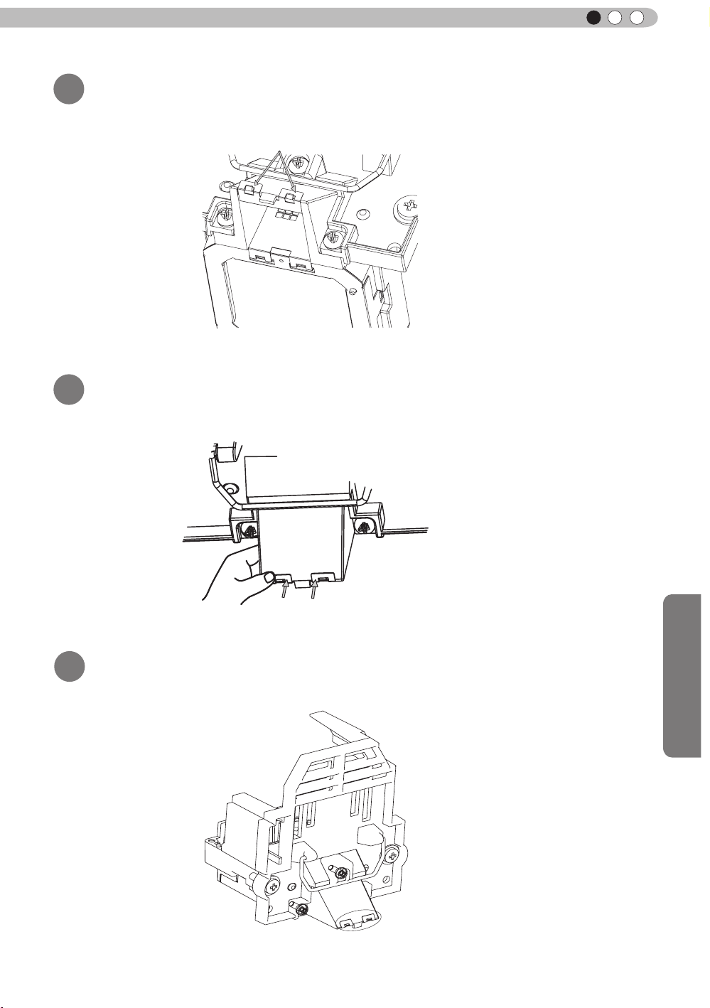
Maintenance
ENGLISH
As shown in Figure 5, make sure that the lamp attachment
3
is coupled with the clasp of the lamp unit
"c"
Figure 5
Bend the "c" section of the lamp attachment (see Figure 5)
4
by pressing it in the direction of the lamp unit
As shown in Figure 7, make sure that the lamp attachment
5
is coupled with the clasp of the lamp unit
bending by pressing
Figure 6
Figure 7
59
Page 60

4
Maintenance
Explanation of the installation/removal of
the lamp attachment
● When replacing the lamp, please do not forget to remove the lamp attachment.
(continued)
Lamp attachment removal procedure
Bend the clasp coupling of the lamp attachment vertically
1
(see Figure 2)
● If you remove it without bending it vertically, it will be difcult to install the next time.
bending
Figure 1
Remove the clasp coupling of the lamp unit and the lamp
2
Figure 2
attachment in the direction of the arrow
Make sure that the clasp is removed from the
3
lamp attachment
60
Figure3
Figure 4
Page 61

Maintenance
ENGLISH
Remove the clasp coupling of lamp attachment on the
4
reverse side and the lamp unit
Figure 5
Attachment of the installation verication seal
After replacing the lamp, attach the "installation
1
verication seal" on the lamp cover
● Attach the installation verication seal at the bottom right of the lamp cover.
installation verication seal
● The installation verication seal states "DOWN45 ° ~ 90 °".
● When the lamp attachment is removed, peel off the attached verication seal and keep it for
further use.
61
Page 62

4
Maintenance
Replacing the Lamp
The lamp is a consumable item. If the image is dark or the lamp is turned off, replace the lamp
unit.
● When the lamp replacement time approaches, a message is displayed on the screen and the condition
is indicated by the indicator. (Reference page: 14 to 15, 70)
CAUTION
●
Do not insert your hands into
the opening of the lamp!
This could cause obvious
deterioration of the
equipment’s function, wounds
and electric shocks.
●
Do not replace the lamp
immediately after the unit has
been used, and allow a cooling
period of 1 hour or more before
replacement. The temperature
of the lamp is still high and this
may cause a burn.
●
Do not apply shock to the
lamp unit. It may cause lamp
blowout.
●
Do not use ammable air duster
to clean the internal parts of the
unit. This may cause re.
MEMO
Usable Lamp Life
●
When using the “Lamp Power”
set at “Normal", the lifetime of
the lamp will be approximately
3000 hours.
This is an average lifetime and
cannot be guaranteed.
●
The lamp life may not reach
3000 hours depending on the
operating conditions.
●
When the lamp has reached
the end of its usable life,
deterioration progresses
rapidly.
●
If the picture becomes dark,
the tint becomes strange, or
the image ickers, promptly the
lamp unit for a new one.
Lamp replacement procedure
Remove the power plug from the
1
outlet
Remove the lamp cover
2
●
Remove the screws with a
Loosen the screws on the lamp unit
3
●
Loosen the screws with a screwdriver.
Pull out the lamp unit
4
●
Grasp the handle and pull out the lamp unit.
screwdriver.
Purchasing the Lamp Unit
Please consult your authorized
dealer.
Lamp Unit
■
Part No.: PK-L2210U
62
Handle
Page 63

Maintenance
ENGLISH
Install the new lamp unit
5
Handle
Tighten the screws of the new lamp
6
unit
●
Tighten the screws with a screwdriver.
CAUTION
●
Use only genuine replacement
parts for the lamp unit. Also,
never attempt to reuse an old
lamp unit. This may cause a
malfunction.
●
Do not touch the surface of a
new lamp. This may shorten
the lamp life and cause lamp
blowout.
MEMO
After Replacing the Lamp
●
Do not place the removed
lamp unit at locations that is
reachable by children or near
combustible items
●
Dispose used lamp units in
the same way as uorescent
lamps. Follow your local
community rules for disposal.
.
Attach the lamp cover
7
●
Insert the top part (with 2 claws) of the lamp cover into
the unit.
●
Fasten the screws with a screwdriver.
63
Page 64

4
Exit
MENU
BACK
Back
Select
Operate
Trigger
Off Timer
Communication Terminal
Network
High Altitude Mode
LAN
Off
Off
Off
Function
Lamp Reset
Reset Lamp Time?
YES
NO
Maintenance
Replacing the Lamp (Continued)
Resetting lamp Time
STAND BY
HDMI 1
ASPECT
LENS.
CONTROL
HIDE
MENU
NATURAL
USER1
USER4
GAMMA
COMPONENT
HDMI 2
ANAMO
C.M.D
PICTURE MODE
DYNAMIC
USER2
USER5 USER6
COLOR
LENS.
TEMP
AP
ON
COMP.
PC
AUTO
ALIGNMENT
USER3
LIGHT
BACK
3D
PIC.
ADJ.
After replacing a new lamp unit, please reset the lamp time.
Description of two methods.
Reset the lamp time from the menu screen.
Display the setting menu
1
Picture Adjust
Picture Mode
Color Temp.
MENU
Select“Function” “Lamp Reset”
2
Gamma
Contrast
Brightness
Color
Tint
Advanced
Exit
MENU
Select
① Select
0
0
0
0
Operate
Natural
6500K
Normal
Reset
Back
BACK
64
Re-conrm
3
● Select
one returns to the previous menu.
② Confirm
“
Yes” and the lamp time is set to zero. Moreover,
Page 65

Maintenance
ENGLISH
Reset the lamp time by remote control.
Insert the power plug to the power
1
outlet
Red Lights
Must operate with the remote
2
control in the standby mode (the
projector is powered, but is not
turned on).
●
Press in the order as shown.
●
Press each button within 2-second intervals and press
the last button for 2 seconds or more.
BACK
OK
HIDE
Press for 2 seconds or more
STAND BY
HDMI 1
ASPECT
LENS.
CONTROL
HIDE
MENU
NATURAL
USER1
USER4
GAMMA
COMPONENT
HDMI 2
ANAMO
C.M.D
PICTURE MODE
DYNAMIC
USER2
USER5 USER6
COLOR
LENS.
TEMP
AP
ON
COMP.
PC
AUTO
ALIGNMENT
BACK
USER3
LIGHT
3D
PIC.
ADJ.
●
[STANDBY/ON] indicator and [LAMP] indicator blink
alternately for 3 seconds. After that, the unit switches to
standby mode.
STANDBY/ON
LAMP
WARNING
CAUTION
●
Reset the lamp time only when
you have replaced the lamp.
●
Never reset the service time when
the lamp is still in use. Otherwise,
the approximate standard for
gauging replacement time may be
inaccurate and lamp blowout may
occur.
65
Page 66

4
Maintenance
Method for cleaning and
replacing lters
Clean the filter regularly or air intake efficiency may deteriorate and malfunction may
occur.
Remove the inner lter.
1
Clean the lter.
2
Lift up while pushing the claw
●
Pull the power plug from the
power outlet.
●
Please turn this unit and if
you put in on a bed or a table,
rst place something soft
like a piece of cloth below.
Then you can put it on top of
it. Otherwise, it may cause
scratches on this unit.
CAUTION
●
Wash the lter with water and dry it in a shaded area.
●
In extremely soiled cases, using a neutral detergent
is recommended. Put on rubber gloves when using a
neutral detergent.
●
After washing the lter with water, make sure that it is
completely dry before reinstalling. Otherwise electric
shock or malfunctions may occur.
●
Do not clean the lter with a vacuum cleaner or air
duster. The lter is soft and may be damaged.
Reinstall the inner lter.
3
Check that the left and
right claws are locked onto
the unit
MEMO
If the lter is damaged or
too dirty to be cleaned.
●
Replace with a new lter. A
dirty lter will dirty the internal
parts of the unit and cause
shadows on the video image.
●
To purchase a new lter or
when it is dirty in the internal
parts, consult your authorized
dealer.
Inner Filter
■
Part No.:
●
Replacement Filter:
PC010661199
66
Page 67

Maintenance
MEMO
ENGLISH
67
Page 68

5
Others
Troubleshooting
Before sending the unit to your authorized dealer for repair, please check
the following points.
The following situations are not malfunctions.
■
You do not need to worry about the following situations if there is no abnormality on the
screen.
●
Part of the top surface or front of the unit is hot.
●
A creaking sound is heard from the unit.
●
An operating sound is heard from the inside of the unit.
●
Color smear occurs on some screens.
■
Perform the following operations when the unit is unable to operate normally due to external
static or noise.
① When the unit is in standby mode, please pull out the power plug, then insert again.
② Press the power button on the unit to turn on the power again.
■
A sound may be heard when the lamp is off but there is no danger.
■
D-ILA device is manufactured using high-precision technology but there may be some missing
pixels or pixels that remain permanently lit up.
Power is not supplied
Is the power cord disconnected? Insert the power cord (plug) rmly.
Is the lamp cover properly shut?
Is the lamp in Cool Down
mode?
Remove the power plug when the unit is
in standby mode and close the lamp cover
properly. After that, insert the plug again.
After the Cool Down mode is complete, turn
on the power again.
Reference page:
29
Reference page:
63
Reference page:
31
Video image does not appear
Is the correct external input
selected?
Is the AV device properly
connected?
Is the power of the AV device
turned on?
Are the correct signals being
output from the AV device?
Is the setting of the input
terminal correct?
Is the video image temporarily
hidden?
Select the correct external input.
Connect the AV device properly.
Turn on the power of the AV device and play
the video.
Set the AV device prope
Set “COMP.” and “HDMI” in the setting menu
according to the input signal.
Press the [HIDE] button to display the video
image again.
rly.
Remote control does not work
Are batteries installed
correctly?
Are batteries exhausted? Replace with new batteries.
Is there an obstructive object
between the remote control
and remote sensor?
Is the remote control held too
far away from the unit?
Match the polarities (
inserting the batteries.
Remove any obstructive objects.
Hold the remote control closer to the sensor
when using.
or ) correctly when
Reference page:
30
Reference page:
23 to 28
Reference page:
30
R
eference page:
23 to 28
Reference page:
48 to 49
Reference page:
34
Reference page:
17
Reference page:
17
Reference page:
21
Reference page:
21
68
Page 69

ENGLISH
The picture cannot be projected
Will the picture icker and
become invisible with HDMI
input?
Please use a short HDMI cable.
Reference page:
24
The image cannot output by HDMI terminal
Is the setup of “Control with
HDMI” function “Off”?
● Even if the “Control with HDMI” function is “On”, there are still some devices cannot reveal image
normally.
Set up the “Control with HDMI” function to “Off”.
Reference page:
48
Color does not appear or looks strange
Is the image correctly adjusted?
Adjust “Color” and “Tint” in the setting menu.
Reference page:
43
Video image is fuzzy
Is the focus correctly adjusted? Adjust the focus.
Is the unit placed too near or too
far away from the screen?
Set the unit at a correct distance from the
screen.
Reference page:
30
Reference page:
19, 21
Video images are missing
Has setting been performed for
screen mask?
Is the display out of position?
Set “Mask” in the setting menu to “Off”.
Alter the “Picture Position” value in the setting
menu to ensure that images are not missing.
Reference page:
33, 48
Reference page:
47
Projected image is dark
Is the lamp near exhaustion?
Check the lamp time on the information menu.
Prepare a new lamp unit or replace as soon
as possible when the lamp is near exhaustion.
Reference page:
62 to 65
The unit works when power is turned on but stops abruptly after a few minutes
Are the air inlets and exhaust
vent blocked?
Is the lter dirty? Clean the lter.
Remove the power plug when the unit is in
standby mode and remove any blocking object.
After that, insert the plug again.
Reference page:
3, 12
Reference page:
66
Power is cut off suddenly
Has setting been performed for
off timer?
Set “Off Timer” in the setting menu to “Off”.
Reference page:
51 to 52
Others
69
Page 70

5
COMP.
Others
In case this message is
displayed
Message Cause (Details)
COMP㧚
䇭NO Input
Lamp replacement
Back
BACK
No device is connected to the input terminal.
The input terminal is connected but there is no signal.
Input the video signals.
A video signal that cannot be used in this unit has been input.
Input video signals that can be used.
* The names of input terminals such as COMP. will be displayed in yellow
This message is displayed when the accumulated lamp time has
exceeded 2900 hours.
To clear the message, press the [Back] button.
Get ready a new lamp unit and replace as soon as possible. Reset
the lamp time after replacing the lamp. (Reference page: 62 to 65)
70
Page 71

ENGLISH
RS-232C Interface
It is possible to control this machine, if it is connected by an RS-232C cross cable (D-Sub9 pin) to a
PC. Otherwise, this machine can be controlled via a computer network by connecting it with a LAN
cable and sending of control commands. Please use it after you have understood this by reading
professional books, or by discussing it with a system administrator.
RS-232C Specications
This unit
Pin No. Signal Function Signal Direction
2 RxD
Receive data PC→This unit
Mode
Character Length
Parity
Start Bit
Stop Bit
Data rate
Data format
●
3 TxD
5 GND
1,4,6 - 9 N/C - -
PC refers to the controller such as a personal computer.
Non-synchronous
8 bit
None
1
1
19200 bps
Binary
Transmit data This unit→PC
Signal ground
Start Bit
-
D6 D7D4 D5D2 D3D0 D1
Stop Bit
TCP/IP-connection
Before you can co
necessary for a connection authentication to send from the projector "PJ_OK" and - within 5 seconds after
sending a "PJREQ" – to receive "PJACK". Please perform this operation – after conrming the operating
status of the projector - again after establishment of a TCP connection, if you cannot send within 5 seconds
"PJ_NG" or could not receive "PJNAK".
ntrol it via LAN, you have to establish a T
Within 5 seconds
Projector
PJ_OK
CP-connection via a "3-way-handshake". It is
PJACK
TCP-layer connection establishment
TCP port number 20554
Three-way handshake
Control PC
Others
Projector Control
PJREQ
Connection authentication procedure
71
Page 72

5
Others
RS-232C Interface (Continued)
Command Format
The command between this unit and the computer consists of “Header”, “Unit ID”, “Command”, “Data”
and “End”.
●
Header (1 byte), Unit ID (2 bytes), Command (2 bytes), Data (n bytes), End (1 byte)
Header
■
This binary code indicates the start of communication.
Binary code
21 Operating command PC → This unit
3F Response command PC → This unit
40 Reference command This unit → PC
06 ACK
Unit ID
■
This code species the unit. The binary code is xed at “8901”.
Command and data
■
Operating command and data (Binary code)
Command Type Description
0000
5057
Connection check
Power supply
Type Description
This unit → PC
(When the command is accepted without error, it
returns to PC)
Check whether communication is available between this
unit and the PC during standby.
During standby
31: Turn on the power.
During power on
30: Turn off the power. (Standby mode)
4950
5243
Input
Remote Control
72
During power on
32: COMP.
33: PC
36: HDMI 1
37: HDMI 2
Sends the same code as the supplied remote control.
●
“Remote control code” (Reference page:73)
Page 73

Reference command and data (Binary code)
Command Type Data description
During standby or power on
30: Standby mode
5057 Power supply
4950 Input
■
End
31: Power-on mode
32: During Cool Down mode
34: Warning mode
During power on
32: COMP.
32: PC
36: HDMI 1
37: HDMI 2
ENGLISH
This code indicates the end of communication. The binary code is xed at
■
Remote control code
●
Binary code is sent during communication.
Remote control button
name
BACK 37 33 30 33 USER 2 37 33 36 44
ON 37 33 30 35 USER 3 37 33 36 45
STAND BY 37 33 30 36 HDMI 1 37 33 37 30
AUTO ALIGNMENT 37 33 31 33 HDMI 2 37 33 37 31
HIDE 37 33 31 44 PIC.ADJ. 37 33 37 32
LENS.AP. 37 33 32 30 GAMMA 37 33 37 35
MENU 37 33 32 45 C.TEMP 37 33 37 36
OK 37 33 32 46 ASPECT 37 33 37 37
LENS CONTROL 37 33 33 30 3D 37 33 38 37
Binary code
37 33 30 31 DYNAMIC 37 33 36 42
37 33 30 32 USER 1 37 33 36 43
37 33 33 34 C.M.D 37 33 38 41
37 33 33 36 ANAMO 37 33 43 35
Remote control button
name
“0A”.
Binary code
PC 37 33 34 36 USER 4 37 33 43 41
COMP. 37 33 34 44 USER 5 37 33 43 42
NATURAL 37 33 36 41 USER 6 37 33 43 43
Others
73
Page 74

5
Others
RS-232C Interface (Continued)
RS-232C Communication Examples
This section shows the communication examples of RS-232C.
Operating command
■
Type Command Description
Connection
check
Power (On)
Power (Off)
Input
(COMP.)
Remote
Control
(MENU)
■
Reference command
PC→This unit: 21 89 01 00 00 0A
This unit→PC: 06 89 01 00 00 0A
PC→This unit: 21 89 01 50 57 31 0A
This unit→PC:
PC→This unit: 21 89 01 50 57 30 0A
This unit→PC: 06 89 01 50 57 0A
PC→This unit: 21 89 01 49 50 32 0A
This unit→PC: 06 89 01 49 50 0A
PC→This unit: 21 89 01 52 43 37 33 32 45 0A
This unit→PC:
06 89 01 50 57 0A
06 89 01 52 43 0A
Connection check.
When power is turned on from
standby mode.
When power is turned off
(standby mode) from power-on
mode.
When video input is set to
component.
When the same operation as
pressing the [MENU] button
on the remote control is made
Type Command Description
Power (On)
Input
(HDMI 1)
PC→This unit: 3F 89 01 50 57 0A
This unit→PC: 06 89 01 50 57 0A
This unit→PC: 40 89 01 50 57 31 0A
PC→This unit: 3F 89 01 49 50 0A
This unit→PC: 06 89 01 49 50 0A
This unit→PC: 40 89 01 49 50 36 0A
When information of poweron mode is acquired.
When information of HDMI 1
input is acquired.
74
Page 75

Copyright and Caution
About Trademarks and Copyright
●
HDMI, HDMI logo and high denition multimedia interface
are trademarks or registered trademarks of HDMI Licensing
LCC.
Caution
ENGLISH
D-ILA Device Characteristics
Do not project still pictures or pictures that have still
segments for a long period of time. The still parts of
the picture may remain on the screen.
Take special notice of images on the screens of
video games and computer programs. There is no
problem when playing normal video images such as
movies.
When Unit is Unused for a Long Time
Prolonged disuse of the unit may effect an error on the
functions. Turn on the power occasionally and operate
the unit.
Usage Environment
●
Avoid direct exposure of screen to direct sunlight
and illumination. Block light using a curtain.
Images can be well projected by darkening the
brightness of the room.
●
Do not use this unit in rooms with cigarette
smoke or oily smoke. This may cause the unit
to malfunction.
Parts Replacement
Maintenance Procedures
Dirt on the cabinet
●
Gently clean dirt on the cabinet with a soft cloth.
In the case of heavy soiling, soak a cloth in water,
wring dry and wipe, followed by wiping again with
a dry cloth. Pay attention to the following as the
cabinet may deteriorate in condition or paint may
come off.
● Do not wipe with thinner or benzene.
● Do not spray with volatile chemicals like
insecticide.
● Do not allow prolonged contact with rubber or
plastic products.
Dirt in the air inlets
●
Use a vacuum cleaner to suck up the dirt.
Otherwise, use a cloth to wipe off the dirt. If dirt
is allowed to accumulate in the air inlets, the
internal temperature cannot be adjusted and this
may cause a malfunction.
Dirt on the lens
●
Clean the dirt using commercial blowers or
lens cleaning papers for cleaning glasses and
cameras. Do not use uid-type cleaning agents.
This may lead to peeling of the surface coating
lm.
( Reference page: 12)
This unit contains parts (optical part, cooling
fan, etc.) that require replacement to maintain
its functioning. The estimated time for parts
replacement varies greatly depending on the
usage and environment. Please consult your
authorized dealer for replacement.
Others
75
Page 76
5
Others
Specications
Product Name
Model Name
Display Panel/Size
Projection Lens
Light-source Lamp
Screen Size
Projection Distance Approx.
Analog Video Input
Format
Digital Video Input
Format
Resolution 1920 dots x 1080 dots
Input terminal
Video Input
Input
HDMI
Projector
D-ILA
DLA-F110-W *1
device
D-ILA
" (1920pixels x 1080pixels) x 3 (Total no. of pixels: Approx. 6.22million)
0.7
2.0 x power zoom lens (1.4:1 to 2.8:1)
(Zoom/Focus: Power)
220 W Ultra-high pressure mercury lamp [Part No. :
Average lifespan:
Approx. 60" to 200" (Aspect ratio: 16:9)
480i, 480p, 576i, 576p, 720p/50 Hz, 720p/60 Hz, 1080i/50
1080i/60
480i, 480p, 576i, 576p, 720p/50 Hz, 720p/60 Hz, 1080i/50
1080i/60 Hz, 1080p/24 Hz, 1080p/50 Hz, 1080p/60 Hz
PC compatible signals
1 system, RCA
Y:1.0Vp-p, 75Ω
Pb/Cb, Pr/Cr:0.7Vp-p,
Also supports R / G / B Sync on G
*
2 system, HDMI 19
Compatible with the HDMIv1.4a standard
* 2 *3
3000
1.8m to 12m
Hz
pin jack
pin
hours (normal mode)
(Reference page: P22)
3
×
75Ω
2(HDCP
×
compliant
PK-L2210U]
Hz
Hz
) * 4
* 5
Input
PC
Output terminal
Trigger terminal
3D synchro
Control terminal
RS-232C terminal 1 system , D-sub 9-pin (male) x1 (External control)
Remote terminal 1 system, stereo mini jack x1 (Remote Control)
LAN terminal 1 system, RJ-45 plug x1
Power Requirements
Power Consumption
Operation Environment
Installation Height
Dimensions
(Width x Height x Depth)
Mass
Accessories
1 system, D-Sub 15 pin VGA
1 system, Φ3.5mmDC Power Jack (
DC OUT 12V, 0.1A
3D synchro emitter dedicated terminal (1 system, mini DIN 3pin)
AC 110V-240V 50/60Hz
350W(3.4A) (
Temperature:
Humidity: 20% to 80%(No condensation)
(Storage Temperature:
Below
About 45
(
Excluding foot, lens, and other protruding parts)
15.1kg
(Please see page 11)
Standby mode:
5ºC to 35ºC
-10℃ to 60℃ )
5000ft (1524 m)
5mmx179mmx472mm
0.9W)
)
76
Page 77

ENGLISH
Regarding -W the color of the main body is some kind of white color. Regarding –B, the color of the
* 1
main body is some kind of black.
D-ILA is the abbreviation for Direct drive Image Light Amplier.
* 2
* 3 D-ILA devices are manufactured using extremely high-precision technology. Pixel effectiveness is
99.99%. Only 0.01% or less of the pixels are either missing or would remain permanently lit up.
* 4 HDCP is the abbreviation for High-bandwidth Digital Content Protection system.
T
he image of HDMI input terminal may not be displayed due to HDCP specication change.
* 5 Ethermet is not supported.
●
Design and specications are subject to change without prior notice.
●
Please note that some of the pictures and illustrations may have been abridged, enlarged or
contextualized in order to aid comprehension. Images may differ from the actual product.
Others
77
Page 78

5
Dimensions
Others
(Unit: mm)
■
Top Surface
Front
Lens center
■
Bottom Surface
472
5
455
Lens
227.5
178.5
103.5
Φ60
24
290
91
59
■■
Back Surface
110
32
Lamp cover
337
Lens
110
92
78
Page 79

Index
ENGLISH
3D
Shorthand for "Three-dimensional"
Operation Guide (Glossary) ............... Page 54
Connection by 3D SYNCHRO
terminal ............................................. Page 26
3D format of [2-1] HDMI ..................... Page 49
Picture Mode of [1] Picture Adjust ...... Page 43
Points of note ................................ Page 4, 54
HDMI
Shorthand for "High-Denition Multimedia
Interface"
Specications
Connection method ............................ Page 24
[2-1] HDMI .......................................... Page 48
(Note on length) ................................. Page 24
Anamorphic Lens
Anamorphic of [3] Installation ............. Page 50
Color
Color temp. of [1] Picture Adjust......... Page 43
Color of [1] Picture Adjust .................. Page 43
Tint of [1
[1-1] Color temp. ............................... Page 44
[1-2-2] Custom Gamma..................... Page 46
[1-2-3] Color Management ................ Page 47
Screen Size
Distance Chart ................................... Page 21
Aspect (Video) and aspect
PC of [2] Input Signal ......................... Page 47
Zoom of [3-1] Lens Control ............... Page 50
Ma
sk
Mask of [2] Input Signal ...................... Page48
Screen Menu
Table Menu Structure ......................... Page 35
[1] Picture Adjust .......................... Page 35, 38
[2] Input Signal ............................. Page 35, 39
[3] Installation ............................... Page 36, 40
[4] Display Setup ...............................
[5] Function ................................. Page
[6] Information .................................... Page 37
Operating procedure .........................
......................................Page 76
] Picture Adjust ....................
Page 43
Page 36
37, 40
Page 42
Batteries
Types .................................................Page 11
How to insert batteries ...................... Page 17
Gamma
Glossary .......................................... Page 53
Gamma of [1] Picture Adjust ............ Page 43
[1-2-2] Custom Gamma ................... P
Spare parts
See "Filters" section
See "Lamp" section
Shift
Shift Amount ....................................... Page 19
Adjustment ......................................... Page 31
Zoom
Magnication ...................................... Page 76
Adjustment ......................................... Page 30
Installation
Angle .................................................. Page 19
Settings ................
Ceiling Mount .................................
Caution .............................................. Page 18
Settings Menu
Structure ............................................ Page 43
Menu operating method ..................... Page 42
Projection Distance
Distance Chart ................................... Page 21
Input Signal
PC signal support table ........
[6] Information .................................... Page 52
Noise
NR. of [1-2] Advanced ........................ Page 44
Filter
Inlet lter location ............................... Page 12
Replacement Filter Number ............... Page 66
Cleaning and Replacement ................ Page 66
Message
Meaning ............................................. Page 70
.............................. Page 47
Page 4,20
.............. Page 22
age 46
Others
79
Page 80

5
Others
Index (continued)
Lamp
Replacement Lamp Number .............. Page 62
Recommended use time .................... Page 62
Lamp time of [6] Information .............. Page 52
Replacement ...................................... Page 62
Lamp power of [1-2] Advanced .......... Page 45
Lamp reset of [5] Function ................. Page 52
How to reset the lamp time .......... Page 64, 65
Notes of Caution ..................................
Remote control
Button placement .............................. Page 17
Instructions ......................................... Page 21
See "Dry battery" section
Lens
[3-1] Lens Control ............................. Page 50
Focus of [3-1] Lens Control ............... Page 50
Zoom of [3-1] Lens Control ............... Page 50
Shift of [3-1] Lens Control .................. Page 50
(Cleaning the lens) .....
........................ Page 75
Page 4
80
Page 81

Mise en oeuvre
Autres
Préparation
Pour commencer
Maintenance
PROJECTEUR D-ILA
DLA-F110
FRANÇAIS
MANUEL D’INSTRUCTIONS
Page 82

1
Pour commencer
Importantes Mesures De Sécurité
IMPORTANT INFORMATIONS
Ce produit conmprend une lampe à
décharge à haute intensité (HID)
contenant du mercure.
Éliminer ces déchets est sujet à la
réglementation de votre communauté
pour des raisons environnementales.
Pour de plus amples informations
concernant leur élimination ou leur
recyclage, veuillez contacter vos
autorités locales ou, pour les É-U,
l’Electronic Industries Allianceo:
http://www.eiae.org.
AVERTISSEMENT:
POUR ÉVITER TOUT RISQUE D’INCENDIE OU
D’ÉLÉCTROCUTION, N’EXPOSEZ PAS CET
APPAREIL À LA PLUIE OU À L’HUMIDITÉ.
AVERTISSEMENT:
CET APPAREIL DOIT ETRE MIS A LA TERRE.
ATTENTION:
Pour réduire les risques d’électrocution, ne retirez
pas le couvercle de l’appareil. Référez-vous à un
technicien qualié.
Ce projecteur est équipé d’une prise comprenant
une che de terre an de respecter les règles du
FCC. Si vous êtes dans l’impossibilité d’insérer la
prise dans la prise murale, contactez votre
électricien.
INFORMATIONS CONCERNANT LES
NUISANCES SONORES DES MACHINES
(seulement en Allemagne)
Modie l’ordonnance 3. GSGV concernant les
nuisances sonores des machines du 18 janvier
1991 : Le niveau de pression sonore à la position de
l’utilisateur est inférieur ou égal à 20 dB (A)
conformément à l’ISO 7779.
INFORMATIONS DU FCC (seulement
aux É-U)
AVERTISSEMENT :
Les transformations ou les modications n’étant pas
approuvées par JVC pourraient annuler le droit de
l’utilisateur d’utiliser l’équipement.
NOTE:
Cet équipement a été testé et a été reconnu comme
respectant les limites des appareils numériques de
classe B, conformément à la partie 15 des règles du
FCC. Ces limites sont conçues pour fournir une protection raisonnable contre les interférences nuisibles.
Cet équipement génère, utilise et peut émettre de
l’énergie sous forme de fréquence radio et, s’il n’est
pas installé et utilisé en accord avec les instructions,
il pourrait causer des interferences nuisibles aux
communications radio. Néanmois, il n’y a aucune
garantie que l’interférence n’apparaitra pas dans une
installation particulière. Si cet équipement cause en
effet des interférences nuisibles à la réception radio ou
TV, ce qui peut être vérié en éteignant et rallumant
l’équipement, l’utilisateur est encouragé à essayer
de corriger l’interférence avec l’une ou plusieurs des
mesures suivanteso:
● Réorientez ou déplacez l’antenne de reception.
● Augmentez la distance entre l’équipement et le
récepteur.
● Connectez l’équipement à une prise ou à un circuit
électrique différent de celui sur lequel le récepteur
est branché.
● Consultez votre revendeur ou un technician
expérimenté en radio / TV pour de l’aide.
À propos du choix de l’emplacement
N’installez pas le projecteur dans un endroit qui ne
peut pas soutenir son poids en toute sécurité.
Si l’emplacement de l’installation n’est pas sufsamment solide, le projecteur risque de tomber ou de se
renverser et de blesser quelqu’un.
.
IMPORTANTES MESURES
DE SÉCURITÉ
L’énergie électrique peut remplir beaucoup de fonctions utiles. Cet appareil a été conçu et fabriqué pour
assurer votre propre sécurité. Mais UNE UTILISATION
INCORRECTE PEUT ENTRAÎNER UN RISQUE POTENTIEL D’ÉLECTROCUTION OU D’INCENDIE. An
de ne pas annuler les dispositifs de sécurité incorporés
dans cet appareil, observez les règles fondamentales
suivantes pour son installation, son utilisation et sa
réparation. Veuillez lire attentivement ces Importantes
mesures de sécurité avant d’utiliser l’appareil.
- Toutes les instructions de sécurité et de fonctionne
ment doivent être lues avant l’utilisation de l’appareil.
- Les instructions de sécurité et de fonctionnement
doivent être conservées à titre d’information.
2
Page 83

Pour commencer
FRANÇAIS
- Tous les avertissements sur l’appareil et dans le mode
d’emploi doivent être compris et acceptés.
- Toutes les instructions de fonctionnement doivent être
suivies.
- Mettre le projecteur près d’une prise de courant, de façon
à pouvoir le brancher et débrancher facilement.
- Débranchez cet appareil de la prise murale avant de le
nettoyer. Ne pas utiliser de netoyyant ou en aérosol.
Utilisez un chiffon humide pour le nettoyage.
- N’utilisez pas d’accessoires non recommandés par le
fabricant de l’appareil car ils pourraient être dangereux.
- N’utilisez pas ce produit près de l’eau. Ne pas l’utiliser
non plus après l’avoir déplacé d’une basse température
à une température élévée. Cela produit une condensation d’humidité qui peut entraîner un incendie, une
électrocution ou d’autres dangers.
- Ne placez pas cet appareil sur un chariot, une table ou
tout autre support instable. L’appareil pourraît tomber,
et ainsi blesser gravement un enfant ou un adulte, ainsi
qu’être ui même sérieusement endommagé. L’appareil
doit être monté conformément aux instructions du
fabricant et doit utiliser un support recommandé par le
fabricant.
- Quand vous utilisez l’appareil sur un chariot, faites attention aux arrêts brusques, aux forces excessives et aux
surfaces accidentées qui pourraient causer un renversement de l’appareil, risquant de l’endommager ou de
blesser l’opérateur.
- Les fentes et les ouvertures du coffret
sont nécessaires pour la ventilation. Elles
assurent un fonctionnement sûr de
l’appareil et le protège d’une surchauffe.
Ces ouvertures ne doivent pas être
bloquées ou recouvertes. (Les ouvertures
ne doivent jamais être bloquées en plaçant
l’appareil sur un lit, un divan, un tapis
ou une surface similaire. Il ne doit pas être
encastré dans un emplacement comme une bibliothèque
ou un bâti sauf si une ventilation correcte existe et si les
instructions du fabricant ont été respectées.)
- An de permettre une meilleure dissipation de la
chaleur,laissez un espace libre tout autour de cet appareil, tel qu’illustré ci-dessous. Lorsque cet appareil se
trouve dans un espace dont les dimensions correspondent à celles indiquées ci-dessous, utilisez un climatiseur
pour que la température soit la même à l’intérieur et à
l’extérieur de cet espace. La surchauffe peut causer des
dommages.
Au moins 150 mm
Au moins
300 mm
Au moins
150 mm
Proj.Avant
Au moins
300 mm
Au moins
200 mm
- Alimentation électrique indiquée sur l'étiquette. Si vous
n’êtes pas sûr du type d’alimentation électrique domestique, consultez un revendeur ou votre entreprise locale
de distribution d’énergie.
- Cet appareil est équipé d’une che à trois broches.
Elle ne peut être branchée que dans une prise secteur
avec mise à la terre. Si vous ne pouvez pas insérer la
che dans la prise, contactez votre électricien an qu’il
installe une prise correcte. N’essayez pas de défaire le
principe de sécurité de la che avec mise à la terre.
- Les cordons d’alimentation doient être positionnés de
façon à ce qu’ils ne soient pas écrasés ou coincés
par des objets placés sous ou contre eux. Faites
particulièrement attention aux cordons au niveau des
portes, des ches et prises ainsi qu’au niveau de la
sortie de l’appareil.
- Pour une meilleure protection pendant un orage ou
quand il est laissé sans surveillance ou n’est pas utilisé
pendant une longue période de temps, débranchez-le
de la prise secteur murale et déconnectez le système de
câbles. Cela évitera qu’il soit endommagé du fait d’un
éclair ou d’une surtension.
- Ne surchargez pas les prises murales, les cordons
prolonga-teurs ou les prises de courant sur les autres
appareils car cela pourrait entraîner un risaue d’incendie
ou d’électrocution.
- Ne jamais insérer d’objet d’aucune sorte à l’intérier de
cet appareil à travers les ouvertures car ils pourraient
toucher des points de tension dangeureuse ou créer
un court circuit qui pourrait entraîner un incendie ou
une éléctrocution. Ne jamais verser de liquide d’aucune
sorte sur l’appareil.
- N’essayez pas de réparer cet appareil vous-même car
l’ouvrir ou retirez les couvercles peut vous exposer à
des tensions dangeureuses ou à d’autres dangers.
Référezvous à un personnel qualié pour toute réparation.
- Débranchez l’appareil de la prise secteur murale et
contactez un réparateur qualié dans les conditions
suivantes:
a) Quand le cordon ou la che d’alimentation secteur
est endomagé.
b) Si un liquide à coulé ou si un objet est tombé
l’intérieurde l’appareil.
c) Si l’appareil a été exposé à la pluie ou à l’eau.
d) Si l’appareil ne fonctionne pas normalement en
suivant les instructions de fonctionnement. Ajustez
uniquement les commandes couvertes par le mode
d’emploi, car un ajustement incorrect des com-
mandes peut endommager l’appareil et demandera
souvent beaucoup de temps à un technicien qualié
pour ramener l’appareil en état de fonctionnement
normal.
e) Si le produit est tombé ou a été endommagé de
n’importe quelle autre façon.
f) Quand l’appareil montre un changement évident
dans ses performances, cela indique qu’il doit être
réparé.
- Quand le remplacement des pièces est
nécessaire,assurezvous que le réparateur a utilisé
les pièces de rechange spéciées par le fabricant ou
possédant les mêmes caractéristiques que la pièce
originale. Un remplacement non autorisé peut entraîner
in incendie,une éléctrocution ou autres dangers.
- Après que cet appareil a subi une réparation ou un
entretien, demandez au réparateur de réaliser les vérications de sécurité pour déterminer si l’appareil est en
état de fonctionnement correct.
3
Page 84

1
Pour commencer
- L’appareil doit être placé à plus de trente centimètres de
sources de chaleur, comme un radiateur, un accumula teur
de chaleur, un fourneau ou tout autre appareil (amplicateurs
inclus) produisant de la chaleur.
- Lors d’un raccordement avec un magnétoscope ou un lecteur
de DVD, vous devez mettre cet appareil hors tension pour
éviter tout choc électrique.
- Ne placez pas de produits combustibles derrière le ventilateur de refroidissement. Par exemple, du tissu, du papier,
des allumettes, une bombe aérosol ou un briquet à gaz qui
présentent des dangers particuliers s’ils sont chauffés.
- Ne regardez pas dans l’objectif de projection quand la lampe
du projecteur est allumée. Une exposition des yeux à une
forte lumière peut affaiblir votre vue.
- Ne regardez pas à l’intérieur de l’appareil au travers de
évents (orices de ventilation), etc. Ner regardez pas directement la lampe de projection en ouvrant le coffret pendant que
celle-ci est allumée. La lampe de projection émet aussi des
rayons ultrviolets et la lumière est si forte que votre vue pourrait être affaiblie.
- Ne pas laisser tomber, frapper ou autrement endommager
la source de lumière (module lampe). La source de lumière
peut se briser et entraîner des blessures. Ne jamais utiliser
de lampe endommagée. Si la source de lumière est cassée,
demandez à votre revendeur d’eefectuer la réparation. Des
fragments provenants d’une lampes brisée pourraient causer
des blessures.
- La lampe utiliser dans ce projecteur est une lampe au mercure sous haute pression. Faire attention lorsque cette lampe
doit être jetée. S’il y a quelque chose que vous ne comprenez
pas, contactez votre revendeur.
- N’effectuez pas de “montage au plafond” du projecteur dans
endroit soumis à beaucoup de vibrations. Les xations pourraient se défaire du fait des vibrations causant ainsi la chute
de l’appareil et une éventuelle blessure physique.
- Utilisez uniquement le cordon fourni conçu pour cet appareil
an d’éviter tout choc éléctrique.
- Pour des raisons de santé, faites une pause de 5 à 15 minutes
toutes les 30 à 60 minutes, an de laisser vos yeux se reposer.
Veuillez éviter de regarder des images en 3D lorsque vous
vous sentez fatigué, lorsque vous ne vous sentez pas bien,
ou en cas d’inconfort. De plus, si vous voyez les images en
double, veuillez ajuster l’équipement et le logiciel de façon à
avoir un afchage correct. Veuillez arrêter d’utiliser l’unité si
vous voyez toujours les images en double après ajustement.
- Tous les trois ans, veuillez procéder à un test interne.
Cette unité est fournie avec les pièces de rechange
nécessaires pour la maintenir en état de marche (par exemple
des ventilateurs de refroidissement). Le délai estimé de
remplacement des pièces varie considérablement en fonction
de l’utilisation et de l’environnement. Pour les remplacements,
veuillez consulter votre détaillant ou le centre de réparation
JVC agréé le plus proche de chez vous.
- Lorsque l’unité est xée au plafond Veuillez noter que nous
n’assumons aucune responsabilité, même pendant la période
de garantie, si le produit est endommagé en raison de
l’utilisation d’éléments métalliques pour la xation au plafond
par vos propres moyens ou si l’environnement d’installation
de ces éléments métalliques n’est pas adapté.Si l’unité est
accrochée au plafond pendant l’utilisation, veuillez faire
attention à la température ambiante de l’unité. Si vous utilisez
un chauffage central, il est possible que la température
au niveau du plafond soit supérieure à la température
normale.
- Les images vidéo peuvent s’incruster dans les
composants électroniques.Veuillez ne pas afcher des
écrans avec des images xes à forte luminosité ou à
fort contraste, comme par exemple les images des jeux
vidéo ou des programmes informatiques. Sur un période
de temps prolongée, ces images peuvent s’inscruster
aux pixels. Il n’y a aucun problème pour la lecture des
images animées, p.ex. d’un métrage vidéo normal.
- Le fait de laisser l'unité inutilisée pendant de longues
périodes risque de causer un dysfonctionnement.
Veuillez allumer l'unité et la laisser fonctionner de
temps en temps.Veuillez éviter d’utiliser l’unité dans
une pièce où l’on fume. Il est impossible de nettoyer les
composants optiques qui seraient contaminés par la
nicotine ou le goudron. Cela risque de provoquer une
dégradation des performances.
- Veuillez regarder les images à une distance égale à
au moins trois fois la hauteur de l’image projetée. Les
personnes photosensibles, atteintes d’une maladie
cardiaque quelconque ou en mauvaise santé ne doivent
pas utiliser les lunettes 3D.
- Le visionnage d'images en 3D peut être à l'origine
de maladies. Si vous ressentez un changement dans
votre condition physique, arrêtez immédiatement le
visionnage et, si nécessaire, consultez un médecin.
- Lorsque vous regardez des images en 3D, il est
recommandé de faire régulièrement des pauses. Étant
donné que la durée et la fréquence des pauses requises
varient d’une personne à l’autre, faites les pauses
nécessaires en fonction de votre propre situation.
- Si votre enfant regarde les images en portant des
lunettes 3D, il doit être accompagné par ses parents ou
par un adulte responsable. L’adulte responsable doit
veiller à éviter les situations dans lesquelles les yeux
de l’enfant se fatiguent, car les réactions à la fatigue
et à l’inconfort, etc., sont difciles à détecter, et il est
possible que la condition physique se détériore très
rapidement. Étant donné que le sens de la vision n’est
pas entièrement développé chez les enfants de moins
de six ans, si nécessaire, veuillez consulter un médecin
pour tout problème en relation avec les images en 3D.
- Pendant l’utilisation de la fonction 3D, le rendu vidéo
peut être différent de l’image vidéo d’origine, en raison
de la conversion de l’image dans le dispositif.
*NE LAISSEZ PAS une personne non
qualiée installer l’appareil.
Demandez au revendeur d’installer l’appareil (par
exemple, la xation au plafond) car cela demande
des connaissances et des techniques spéciales.
Si l’installation est réalisée par une personne non
qualiée,cela pourrait entraîner des blessures
personnelles ou une éléctrocution.
4
Page 85

Pour commencer
Importantes Mesures De Sécurité (Suite)
CONNEXION ELECTRIQUE
AVERTISSEMENT:
Ne débranchez pas la fiche principale de cet appareil.
AVERTISSEMENT:
CET APPAREIL DOIT ETRE MIS A LA TERRE.
Aux É-U et au Canada seulement.
N’utilisez que le cordon d’alimentation suivant.
Cord. d‘alimentation
Cord. d‘alimentation
Pour le Royaume-Uni
Pour les pays du continent
européen
La tension d’alimentation secteur de cet appareil est de
110V – 240V CA. N’utilisez que le cordon d’alimentation
désigné par nos revendeurs pour la sécurité et la compatibilité électromagnétique (EMC).
Assurez- vous que le cordon d’alimentation utilisé pour le
projecteur correspond bien au type de prise de votre pays.
Consultez votre revendeur.
Si la fiche existante ne convient pas aux prises de courant
de votre maison ou si le cordon est trop court pour atteindre
une prise de courant, procurez-vous un cordon prolongateur
ou un adapteur de sécurité approuvé ou consultez votre
revendeur.
Si la fiche secteur etait coupée, jetez la prise immédiatement, pour éviter tout danger d’électrocution par une
connexion accidentelle à l’alimentation secteur. Si la
nouvelle fiche secteur doit être adapté, suivez les instructions données ci-dessous.
CONNEXION ELECTRIQUE
(Royaume-Uni seulement)
REMPLACEMENT DU FUSIBLE:
Fusibles
Lors du remplacement du fusible, assurez-vous d’utiliser
seulement un fusible de valeur correcte et de type
approuvé. Remettez en place le couvercle du fusible.
EN CAS DE DOUTE —— CONSULTEZ UN ELECTRICIEN QUALIFIE.
Ouvrez le compartiment à fusible avec la lame d’un
tournevis et remplacer le fusible.
(* Voir l’illustration ci-dessous.)
IMPORTANT
(Eureope seulement)
:
Vert et jaune
Bleu
Marron
Les codes couleurs des fils du cordon d’alimentation de cet
appareil sont les suivants:
Terre
Neutre
Sous tension
Comme ces couleurs ne correspondent peut être
pas avec les couleurs identifiant les bornes de votre
fiche. Procédez comme suit:
Le fil coloré en vert et jaune doit être connecté à la
borne marquée M par la lettre E ou le symbole de
terre ou de couleur vert et jaune.
Le fil qui est coloré en bleu doit être connecté à la
borne qui est marqué par la lettre N ou de couleur
noire.
Le fil qui est coloré en marron doit être connecté à
la borne qui est m
arquée de la lettre L ou de couleur
rouge.
Cher(e) client(e),
Représentant européen de la société Victor Company of Japan, Limited:
JVC Te
chnical
Services Europe GmbH
Postfach 10 05 04
61145 Friedberg
Allemagne
Cet appareil est conforme aux directives et normes européennes en vigueur concernant la compatibilité électromagnétique
et à la sécurité électrique.
FRANÇAIS
5
Page 86

1
Pour commencer
ENGLISH
ENGLISH
Information for Users on Disposal of Old Equipment and Batteries
[European Union only]
These symbols indicate that equipment with these symbols
should not be disposed of as general household waste. If you
want to dispose of the product o r battery, please consider the
collection systems or fa cilities for appr opriate recycling.
Notice: The sign Pb below the symbol for batteries indicates that
this battery contains lead.
Products
Battery
DEUTSCH
Benutzerinformationen zur Entsorgung alter Geräte und Batterien
[Nur Europäische Union]
Diese Symbole zeigen an, dass derartig gekennzeichnete Geräte
nicht als normaler Haushaltsabfall entsorgt werden dürfen. We
nden Sie sich zur Entsorgung des Produkts oder der Batterie an
die hierfür vorgesehenen Sammelstellen oder Einrichtungen,
damit eine fachgerechte Wiederverwertung möglich ist.
Produkte
dass diese Batterie Blei enthält.
Batterie
Hinweis: Das Zeichen Pb unterhalb des Batteriesymbols gibt an,
FRANÇAIS
Informations relatives à l’élimination des appareils et des piles usagés, à
l’intention des utilisateurs
[Union européenne seulement]
Si ces symboles gurent sur les produits, cela signie qu’ils ne
doivent pas être jetés comme déchets ménagers. Si vous voulez
jeter ce produit ou cette pile, veuillez considérer le système de
collection de déc hets ou les centres de recyclage appropriés.
Notication: La marque Pb en dessous du symbole des piles
Produits
Pile
indique que cette pile contient du plomb.
Informatie voor gebruikers over het verwijderen van oude apparatuur en
batterijen
[Alleen Europese Unie]
Deze symbolen geven aan dat appara tuur met dit symbool niet
mag worden weggegooid als algemeen huishoudelijk afval. Als u
het product of de batterij wilt weggooien, kun t u inzamelsystemen
of faciliteiten voor een geschikte recycling gebruiken.
Opmerking: Het teken Pb onder het batterijsymboo l geeft aan
dat deze batterij lood bevat.
Batterij
Producten
6
NEDERLANDS
Page 87

Pour commencer
FRANÇAIS
ESPAÑOL / CASTELLANO
Información para los usuarios sobre la eliminación de baterías/pilas usadas
Estos símbolos indican que el equipo con estos símbolos no debe
desecharse con la basura doméstica. Si desea desechar el pro
ducto o batería/pila, acuda a los sistemas o centros de recogida
para que los reciclen debidamente.
Atención: La indicación Pb debajo del símbolo de batería/pila
indica que ésta contiene plomo.
Productos
Baterías/pilas
[Sólo Unión Europea]
ITALIANO
Informazioni per gli utenti sullo smaltimento delle apparecchiature e batterie
obsolete
[Solo per l’Unione Europea]
Questi simboli indicano che le apparecchiature a cui sono relativi
non devono essere smaltite tra i riuti domestici generici. Se si
desidera smaltire questo prodotto o questa batteria, prendere in
considerazione i sistem i o le strutture di raccolta appropriati per
il riciclaggio corretto.
Nota: Il simbolo Pb sotto il simbolo delle batter ie indica che
Prodotti
questa batteria contiene piombo.
Batteria
PORTUGUÊS
Informação para os utilizadores acerca da eliminação de equipamento usado e
pilhas
[Apenas União Europeia]
Estes símbolos indicam que o equipamento com estes símbolos
não deve ser eliminado juntamente com o restante lixo doméstico.
Se p retende eliminar o produto ou a pilha, utilize os sistemas de
recolha ou instalações para uma reciclagem apropriada.
Aviso: O sinal Pb abaixo do símbolo para pilhas indica que esta
pilha contém chumbo.
Pilha
Produtos
ΕΛΛΗΝΙΚΑ
Πληροφορίες για την απόρριψη παλαιού εξοπλισμού και μπαταριών
[ Ευρωπαϊκή Ένωση μόνο ]
Αυτά τα σύμβολα υποδηλώνουν ότι ο εξοπλισμός που τα φέρει
δεν θα πρέπει να απορριφθεί ως κοινό οικιακό απόρριμμα . Εάν
επιθυμείτε την απόρριψη αυτού του προϊόντος ή αυτής της
μπαταρίας , χρησιμοποιήστε το σύστημα περισυλλογής ή
εγκαταστάσεις για ανάλογη ανακύκλωση .
Σημείωση : Το σύμβολο Pb κάτω από το σύμβολο μπαταρίας
Προϊόντα
υποδηλώνει ότι η μπαταρία περιέχει μόλυβδο .
Μπαταρία
7
Page 88

1
Pour commencer
Brugerinformation om bortskaffelse af gammelt udstyr og batterier
DANSK
Disse symboler angiver, at udstyr med disse symboler ikke må
bortskaffes som almindeligt husholdningsaffald. Hvis du ønsker at
smide dette produkt eller batteri ud, bedes du overveje at bruge
indsamlingssystem et eller steder, hvor der kan ske korrekt gen
brug.
Bemærk: Tegnet Pb under symbolet for batterierne angiver, at
Produkter
dette batteri indeholder bly.
Batteri
[Kun EU]
SUOMI
Tietoja vanhojen laitteiden ja akkujen hävittämisestä
[Vain Euroopan unioni]
Nämä symbolit ilmaisevat, että symboleilla merk ittyä laitetta ei
tulisi hävittää tavallisen kotitalousjätteen mukana. Jos haluat hävit
tää tuotteen tai sen akun, tee se hyödyntämällä akkujen
keräyspisteitä tai muita kier rätyspaikkoja .
Huomautus: Akkusymbolin alapuolella oleva Pb-merk intä tarkoit
taa, että akku sisältää lyijyä.
Tuotteet
Akku
SVENSKA
Information för användare gällande bortskaffning av gammal utrustning och
batterier
[Endast den Europeiska unionen]
Dessa symboler indikerar att utrustning med dessa symboler inte
ska hanteras som vanligt hushållsavfall. Om du vill bortsk affa
produkten eller batteriet ska du använda uppsamlingssystem eller
inrättningar för lämplig återvinning.
Observera! Märkningen Pb under symbolen för batterier indikerar
att detta batteri innehåller bly.
Batteri
Produkter
NORSK
Opplysninger til brukere om kassering av gammelt utstyr og batterier
[Bare EU]
Disse symbolene viser at utstyr med dette symbolet, ikke skal
kastes sammen med vanlig husholdningsavfall. Hvis du vil kass
ere dette produkte t eller batteriet, skal du vurdere å bruke innsam
lingssystemene eller andre muligheter for riktig gjenbruk.
Merk: Tegnet Pb under symbolet for batterie r, viser at batteriet
Produkter
inneholder bly.
Batteri
8
Page 89

Pour commencer
FRANÇAIS
Сведения для пользователей по утилизации старого оборудования и
батарей
[только для Европейского союза]
Данные символы указывают на то, что оборудование, на
которое они нанесены, не должны утилизироваться, как
обычные бытовые отходы. При необходимости утилизировать
такое изделие или батарею обратитесь в специальный пункт
сбора для их надлежащей переработки.
Уведомление: Надпись Pb под символом батар ей указывает
Изделия
на то, что данная батарея содержит свинец.
Батарея
Informace pro uživatele k likvid aci starého zařízení a baterií
[Pouze Evropská unie]
Tyto symboly označují, že produkty s těmito symboly se nesmí
likvidovat jako běžný odpad. Pokud chcete produkt nebo baterii
zlikvidovat, využijte sběrný systém nebo jiné zařízení, které zaji stí
řádnou recyklaci.
Upozornění: Značka Pb pod symbolem pro ba te rie znamená, že
Produkty
tato baterie obsahuje olovo.
Baterie
Informacje dla użytkowników dotyczące poz bywania się zużytego sprzętu i
baterii
[Tylko kraje Unii Europejskiej]
Te symbole oznaczają, że sprzę tu nie należy wyr zucać razem z
odpadami gospodarczymi. Jeśli trzeba po zbyć się tego produktu
lub ba terii, proszę skorzystać z systemu odbioru lub urządzeń do
zbió rki odpadów elektronicznych, w celu odpowiedniego ponowne
go ich przetworzenia.
Uwaga: Oznaczenie Pb, znajdujące się pod symbole m baterii
Produkty
wskazuje, że ta bateria zawiera ołów.
Bateria
MAGYAR
Felhasználói információ az elhasznált be rendezések és akkumulátorok
elhelyezéséről
[Csak az Európai Unióban]
Ez a szimbólum azt jelzi, hogy a berendezés nem helyezhető az
általános háztartási hulladék közé. Ha meg szeretne szabadulni a
terméktől vagy az akkumulátortól, akkor legyen tekintettel az
gyűjtő rendszerre vagy intézményekre a megfelelő hasznosítás
érdekében.
Megjegyzés: Az alábbi Pb szimbólum - ha az akkum ulátoron
Termékek
megtalálható - azt jelzi, hogy az akkumulátor ólmot
tartalmaz.
Akkumulátor
POLSKI
9
Page 90

1
Pour commencer
Contenu
Pour commencer
Importantes Mesures De Sécurité...2
Contenu ...........................................10
Accessoires/Accessories
facultatifs.........................................11
Vérier les accessoires ............................. 11
Accessoires facultatifs ............................... 11
Commandes et fonctionnalités .....12
Boîtier - Proj. Avant....................................12
Boîtier - Bas .
Boîtier - Arrière ..........................................13
Boîtier - À propos de l'afchage des
indicateurs .................................................14
Boîtier - Afchage de mise en garde et
conrmation/réaction .................................15
Boîtier - Terminaux d'entrée ......................16
Comment insérer les piles dans la
télécommande control ...............................17
..............................................12
Préparation
À propos de l’installation ...............18
Points importants concernant
l'installation ................................................ 18
Installation le projecteur et l’écran ............. 19
Régler l’angle .........................................19
Décalage ................................................19
Fixation du projecteur ................................ 20
Taille de l’écran et distance de projection .. 21
Portée efcace de la télécommande ......... 21
À propos des connexions ..............22
Types of possible input signals (PC
compatible) ................................................22
Connexions à l'unité ..................................23
Connexion du cordon d'alimentation
(fourni) .......................................................29
Mise en oeuvre
Opérations de base ........................30
Procédures des opérations de base .............30
Opérations utiles fréquemment utilisées ...32
Régler de la taille de l’écran ................... 32
Masquage de la zone périphérique d’une
image ...................................................... 33
Désactiver temporairement la vidéo .......34
Réglage de la correction du trapèze ......34
Réglages et paramètres dans le
menu ................................................35
Structure de la hiérarchie des menus
(résumé) ....................................................35
Boutons pour les opérations dans les
menus ........................................................ 41
Procédures pour les opérations dans
les menus ..................................................42
Description des éléments de menu ........... 43
Guide des opérations (glossaire)..53
Maintenance
Explication concernant
l'installation/le démontage de
l'accessoire de lampe ...................58
Procédure de remplacement de
l'accessoire de lampe ...............................58
Procédure de démontage de
l'accessoire de lampe ...............................60
Mise en place du joint de vérication
de l'installation ...........................................61
Remplacement de la lampe .......62
Procédure pour le remplacement
de la lampe ................................................62
Remettre à zéro le temps lampe ...............64
Nettoyage et remplacement
du ltre ............................................66
Autres
Dépannage ......................................68
Au cas où ce message s’afche ...70
Interface RS-232C ...........................71
Caractéristiques RS-232C ......................... 71
Connextion TCP/IP .................................... 71
Format des commandes ............................ 72
Exemples de communication RS-232C ..... 74
Droits d’auteurs et mise en
garde ................................................75
À propos des marque de commerce
et droits d’auteurs ......................................75
Mises en garde ..........................................75
Caractéristiques .............................76
Dimensions ................................................ 78
Sommaire ........................................79
10
Page 91

Pour commencer
FRANÇAIS
Accessoires/Accessories facultatifs
Vérier les accessoires
Télécommande ...........................................................................1 pièce
Piles AAA (pour conrmation du fonctionnement) ......................2 pièce
Cordon d’alimentation Pour le marché américain (2 m) .............1 pièce
Cordon d’alimentation Pour le marché européen (2 m)..............1 pièce
Cordon d’alimentation pour le R.U. (2 m) ...................................1 pièce
Accessoire de lampe ..................................................................1 pièce
Joint de vérication de l'installation ............................................1 pièce
●
Le manuel d’instructions, la carte de garantie ainsi que les autres documents imprimés sont également
inclus.
Accessoires facultatifs
Veuillez vérier auprès de votre revendeur agréé pour de plus amples détails.
●
Lampe de rechange: PK-L2210U
●
Filtre de rechange: ltre noir: PC010661199
●
Remplacement de l'accessoirs de lampe: PC010685599
●
3Lunettes 3D : PK-AG
●
Émetteur de synchronisation 3D : PK-EM
11
Page 92

1
Pour commencer
Commandes et fonctionnalités
Boîtier - Proj. Avant
③ Indicateur
STANDBY/ON LAMP WARNING
④ Sorties d’air
① Objectif
Il s’agit d’un objectif de projection. Veuillez ne
pas regarder dedans en cours de projection.
② Récepteur de la télécommande
(avant)
Lorsque vous utilisez la télécommande, veuillez
la pointer vers cette zone.
* Il y a aussi un récepteur de télécommande à
l’arrière.
Boîtier - Bas
⑥
Bouton de fonctionnement
⑤ Entrées
manuel du capot
coulissant
① Objectif
② Récepteur de la
télécommande (avant)
③ Indicateur
Pour les détails, veuillez vous reporter à “À
propos de l’afchage des indicateurs”.
(Page de référence: 14)
④ Sorties d’air
L’air chaud est évacué an de refroidir l’intérieur
de l’appareil.
Veuillez ne pas obstruer les orices de
ventilation.
⑤ Entrées (sur trois points à
l’arrière et sur la base)
Pour refroidir l’intérieur de l’unité, l’air est
aspiré. Ne bloquez pas les orices, n’empêchez
pas la sortie de l’air chaud. Vous risquez sinon
de provoquer une panne de l’appareil.
* Il y a des entrées sur deux points à droite et à
gauche de la face arrière.
(Page de référence: 13)
④ Sorties
d’air
12
⑦ Pieds
⑥ Bouton de fonctionnement
manuel du cache-lentille
Pour ouvrir le cache-lentille,, appuyez dessus.
Il est utilisé pour la maintenance et ne sert pas
dans le cadre de l’utilisation normale.
⑦ Pieds
Vous pouvez ajuster la hauteur (0 à 5 mm) en
tournant les pieds.
Page 93

Pour commencer
FRANÇAIS
Commandes et fonctionnalités (Suite)
Boîtier - Arrière
⑤ Entrées
⑨ Couvercle de
la lampe
⑤ Entrées
⑧ Terminal
d’entrée
⑫ Terminal d’entrée
de l’alimentation
⑧ Terminal d’entrée
Il y a aussi des terminaux autres que le terminal
d’entrée pour les images vidéo, comme ceux
utilisés pour le contrôle ou pour les équipements
optionnels. Voir "Terminaux d'entrée" pour
de plus amples informations concernant les
terminaux. (Page de référence: 16)
⑨ Couvercle de la lampe
Lors du remplacement de la lampe de source
lumineuse, enlevez ce capot.
(Page de référence: 62)
⑩ Panneau de mise en oeuvre
Pour plus de détails, voir l’illustration “Panneau
de contrôle”.
Panneau de mise en oeuvre
■
⑩ Panneau de mise en oeuvre
⑪ Section réceptrice de lumière de la
télécommande (arrière)
⑪ Section réceptrice de lumière
de la télécommande (arrière)
Lorsque vous utilisez la télécommande,
veuillez la pointer vers cette zone.
* Il y a aussi une section réceptrice de lumière
à l’arrière.
⑫ Terminal d’entrée de
l’alimentation
Il s’agit du terminal utilisé pour l’arrivée de
l’alimentation électrique. La connexion se fait
avec le cordon d’alimentation fourni. (Page de
référence: 29)
STANDBY/ON
Pour allumer/éteindre l’a
INPUT
Pour changer d’entrée
OK
Pour sélectionner ou conrmer
ppareil
Bouton gauche
Bouton bas
Pour afcher le menu
MENU
Bouton Haut
Bouton droit
BACK
Pour retourner au menu précédent
13
Page 94
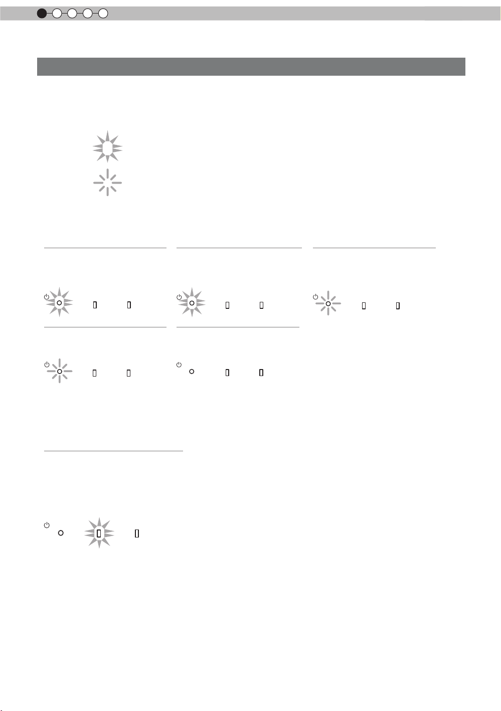
1
Pour commencer
Commandes et fonctionnalités (Suite)
Boîtier - À propos de l'afchage des indicateurs
Les mises en garde et les indications utilisées en mode de fonctionnement normal de cette unité sont
afchées avec les indicateurs [VEILLE / MARCHE], [LAMPE], [MISE EN GARDE] sur l’avant de l’unité.
Signication des icônes afchées :
Afchage des indicateurs lumineux.
Les indicateurs s’afchent en clignotant.
Afchage du mode d’opération
Afchage de la couleur et xe/clignotant de l’indicateur [VEILLE / MARCHE].
STAND BY
Pendantlamiseenveille
STANDBY/ON
STAND BY
Lorsque"Cacher"estréglésurMARCHE
STANDBY/ON
Allumé (Rouge)
LAMP WARNING
Eteint (vert)
LAMP WARNING
STAND BY
Pendantl'activationdelalampe
(environ1minute)
STANDBY/ON
Allumé (vert)
LAMP WARNING
Tout arrêt
Pendantlaprojectiond'images
STANDBY/ON
LAMP WARNING
STAND BY
Pendantlapériodederefroidissement
STANDBY/ON
Eteint (Rouge)
LAMP WARNING
Indication du délai de remplacement de la lampe
Afchage xe/clignotant de l’indicateur [LAMPE]. De plus, l’indicateur [VEILLE / MARCHE], qui indique le
mode de fonctionnement de l’unité, s’afche ainsi que décrit ci-dessus. (Page de référence: 76)
LAMP Allumé (orange)
Le moment de remplacer la
lampe est proche (Lorsque le
temps cumulé d’utilisation de la
lampe a dépassé 2900 heures)
STANDBY/ON
LAMP WARNING
14
Page 95

Pour commencer
FRANÇAIS
Commandes et fonctionnalités (Suite)
Boîtier - Afchage de mise en garde et conrmation/réaction
Afchage de mise en garde
Les mises en garde vous sont adressées par le biais de l’afchage (répété) des indicateurs [MISE EN
GARDE] et [LAMPE]. De plus, l’indicateur [VEILLE / MARCHE], qui indique le mode de fonctionnement de
l’unité, s’afche en même temps ainsi que décrit ci-dessus.
Sur activation du mode de mise en garde, la projection est interrompue pendant environ 60 secondes et
le ventilate
ur de refroidissement est déclenché. Ve
électrique une fois que le ventilateur s’est arrêté. Ensuite, veuillez procéder aux vérications suivantes et
prendre les mesures correctives appropriées.
Diagramme d'état de
l'allumage xe/clignotant
des indicateurs lumineux
Fréquence de
clignotement
1 fois
STANDBY/ON
Afchage
LAMP WARNING
(*)
Rouge
(
2 fois
)
3 fois
du mode
4 fois
1 fois
STANDBY/ON
Afchage
du mode
STANDBY/ON
LAMP WARNING
orange
(
Clignotement
simultané
LAMP WARNING
orange
(
Rouge
) (
(Rouge)
)
2 fois
3 fois
)
4 fois
1 fois
2 fois
Afchage
du mode
3 fois
uillez débrancher le cordon d’alimentation de la prise
Signication
Dysfonctionnements de l
alimentation d’énergie
e ventilateur de
L
refroidissement est arrêté
Température interne trop
élevée
Température externe trop
élevée
Conrmation et mesures
correctives
’
●
Assurez-vous que rien
ne bloque les entrées d
air.
●
Assurez-vous que la
température externe est
normale.
Action
Laissez l'appareil refroidir
le temps qu''il faut.
Circuit électrique anormal
S’il y a un problème avec le
cache-lentille
Allumez l’appareil à
nouveau.
●
Assurez-vous que l
appareil n’a pas subit de
choc d’impact pendant
La lampe ne s’allume pas et
l’appareil est incapable de
projeter les images
qu’il fonctionnait.
●
Assurez-vous que la
lampe et le couvercle
de lampe sont installés
La lampe s’éteint pendant la
projection
correctement.
●
Vériez que rien ne
bloque la fermeture
automatique de
l'objectif.
Le couvercle de la lampe
est démonté
Action
Allumer l’appareil à
nouveau.
’
’
Si l’indicateur d’avertissement s’allume à nouveau, attendez que le ventilateur de refroidissement s’arrête.
Débranchez ensuite le câble d’alimentation de la prise électrique.
Appelez votre détaillant agréé pour faire réparer l’appareil.
(*)Si le délai prévu de remplacement de la lampe est dépassé, il se peut que l'indicateur s'allume.
15
Page 96

1
Pour commencer
Commandes et fonctionnalités (Suite)
Boîtier - Terminaux d'entrée
① HDMI 1 ② HDMI 2 ③ LAN
⑤ COMPOSANTE
④ RS-232C
⑨ TÉLÉCOMMANDE
⑥ SYNCHRO 3D
⑦ PC
① Terminal HDMI 1
Vous pouvez connecter un équipement muni
d’une sortie HDMI, etc. Le branchement se fait
sur l’orice à verrouillage M3. Profondeur de
vissage de l’orice 3 mm.
(Page de référence: 24)
② Terminal HDMI 2
Vous pouvez connecter un équipement muni
d’une sortie HDMI, etc. Le branchement se fait
sur l’o
rice à verrouillage M3. Profondeur de
vissage de l’orice 3 mm.
(Page de référence: 24)
③ Terminal LAN “RJ-45”
Il s’agit d’un terminal LAN. Si vous connectez
un PC externe, il est possible de contrôler cette
unité en envoyant des commandes de contrôle.
(Page de référence: 28)
④ Terminal RS-232C
(D-Sub mâle 9 broches)
Il s’agit d’un terminal standard d’interface RS232C. Si vous connectez un PC externe, il est
possible de contrôler cette unité.
(Page de référence: 27)
⑤ Terminal COMPOSANTE “RCAx3”
Il est aussi utilisé comme terminal d’entrée
pour les signaux RVB (V sur Sync), les signaux
composante (Y, Cb, Cr), les signaux au format
DTV (Y, Pb, Pr). Il peut aussi se voir connecter
des périphériques équipés avec une sortie de
s
ignaux, etc. (Page de référence: 25)
⑧ DÉCLENCHEMENT
⑥ Terminal SYNCHRO 3D
Émetteur de synchronisation 3D : on peut y
connecter le PK-EM1 (vendu séparément) pour
pouvoir proter de contenu vidéo en 3D. (Page
de référence: 26)
⑦
Terminal PC “D-Sub 15 broches”
Ce terminal d’entrée est utilisé pour les
signaux des ordinateurs individuels (PC)
uniquement (signaux vidéo RVB et signaux
d
e synchronisation). Utilisez ce terminal pour
connecter le terminal de sortie d’afchage d’un
ordinateur, etc. (Page de référence: 26)
⑧ Terminal de DÉCLENCHEMENT
(
Terminal de sortie d’alimentation CC avec 12
V CC, 100 mA. Ce terminal est utilisé pour
les signaux de sortie qui contrôlent les écrans
motorisés commandés par la commande de
DÉCLENCHEMENT D’ÉCRAN. Veuillez noter que
toute connexion incorrecte risque d’endommager
votre équipement. (Pointe = +12 V CC, Manchon
= GND) (Page de référence: 27, 51)
)
⑨ Terminal TÉLÉCOMMANDE pour
“
mini-prise stéréo”
Au cas où il se révèlerait impossible d’utiliser
la télécommande en raison de l’installation du
BOÎTIER dédié de cette unité ou d’une projection
arrière, vous pouvez installer une section de
réception externe. Ce terminal est utilisé pour
établir la connexion entre le récepteur externe
et cette unité. Mais il n’existe pas de récepteur
externe. Dès lors, veuillez prendre contact avec
votre centre de rép
(Page de référence: 28)
aration JVC agréé.
16
Page 97

Pour commencer
FRANÇAIS
BACK
HIDE
LIGHT
C.M.D
PC
HDMI 1
STAND BY
ASPECT
HDMI 2
ANAMO
COMP
.
LENS.
CONTROL
MENU
GAMMA
AP
LENS.
ADJ.
PIC.
ON
NATURAL
3D
USER4
USER5 USER6
PICTURE MODE
COMPONENT
TEMP
COLOR
AUTO
ALIGNMENT
DYNAMIC
USER1
USER2
USER3
Commandes et fonctionnalités (Suite)
■
Télécommande
Pour éteindre l’appareil
Pour régler la taille de
l'écran
(Page de référence:32)
Anamorphique
Pour contrôler l’objectif
(Page de référence:30)
Pour masquer
temporairement l’image
(Page de référence: 34)
Afcher / Masque le menu
(Page de référence:41)
Pour régler la température
de couleur
Pour régler le gamma
Pour éteindre l’appareil
Pour changer d'entrée
(Page de référence: 30)
Clear Motion Drive
Alignement Auto
(Page de référence: 49)
Pour allumer les boutons de la télécommande pour 7 secondes
Pour sélectionner ou conrmer
Pour retourner au menu précédent
(Page de référence: 41)
Pour changer de mode
Ouverture
Réglages de Qualité image
sélectionnés de façon séquentielle, par
exemple contraste et luminosité. Les
éléments disponibles diffèrent selon les
modèles ou les modes de qualité.
Comment insérer les piles dans la télécommande control
①
●
●
●
S’il est nécessaire de rapprocher la télécommande du projecteur pour qu’elle fonctionne, cela signie
que les piles sont faibles. Quand cela survient, remplacer les piles. Insérer les piles selon les marques
.
Assurez-vous d’insérer le côté en premier.
Si une erreur survient lors de l’utilisation de la télécommande, retirez les piles et attendez 5 minutes.
Remettez en place les piles et utilisez la télécommande.
②
③
17
Page 98
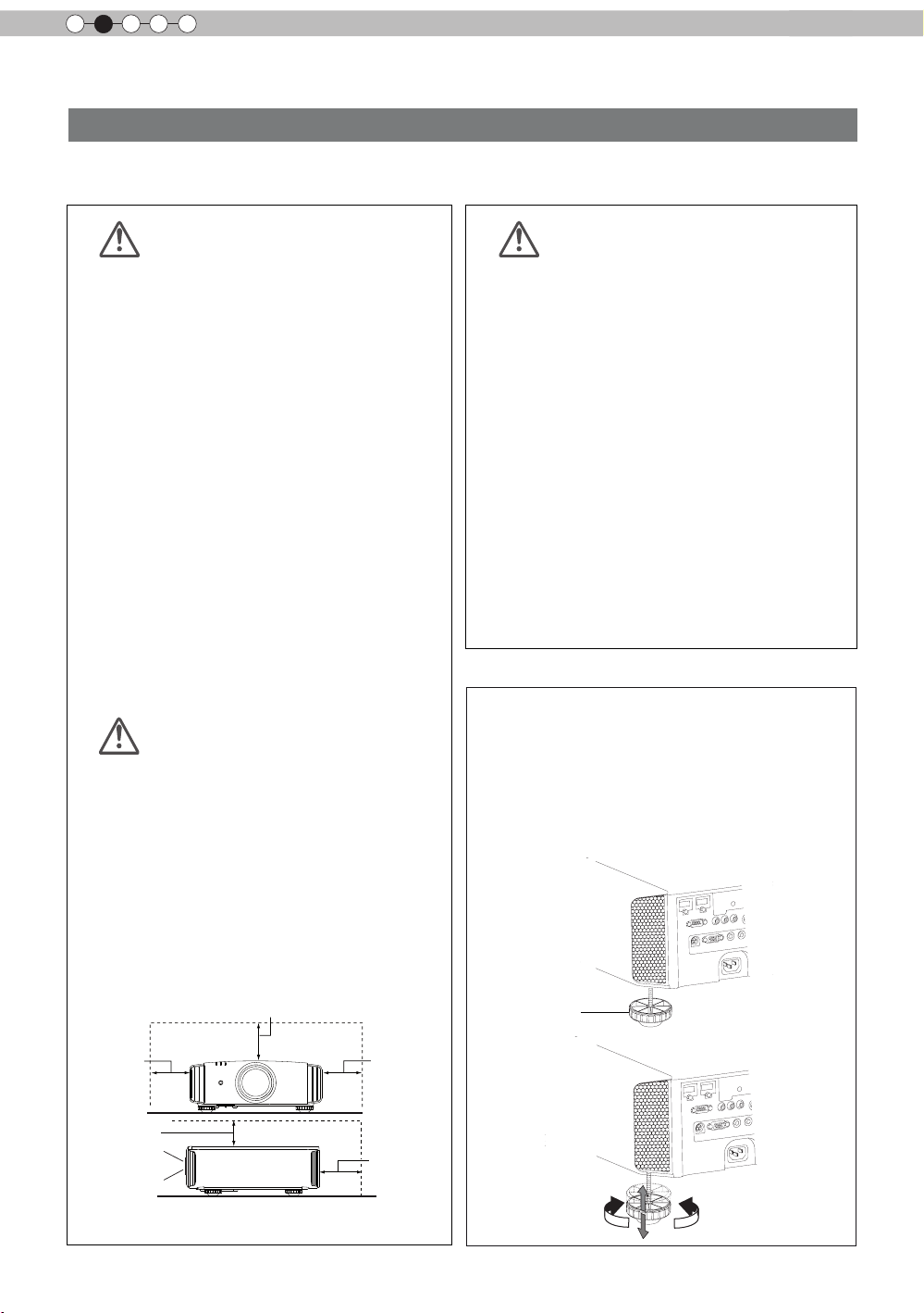
2
Au moins 150 mm
AVERTISSEMENT
AVERTISSEMENT
AVERTISSEMENT
Préparation
À propos de l’installation
Points importants avant l'installation
Veuillez lire attentivement ce qui suit avant d’installer cette unité.
Environnement d’installation
Cette unité est un appareil de précision. Dès lors, veuillez
éviter de l’installer ou de l’utiliser dans les endroits
suivants. Vous vous exposeriez sinon à un risque
d’incendie ou de dysfonctionnement.
• Endroits poussiéreux, mouillés et humides
• Endroits avec présence de suie ou enfumés
• Sur la surface d
douce
• Les endroits soumis à des températures élevées -
comme ceux directement exposés au soleil
• Les endroits soumis à des températures trop élevées ou
trop basses
Plage de température admissible en fonctionnement :
+5 ºC à +35ºC
Plage d’humidité admissible en fonctionnement : 20% ~
80% (sans condensation)
Plage de température admissible en stockage : -10ºC à
+60ºC
’
• Si l
unité est installée pendant une période prolongée
dans une pièce exposée à la suie et/ou enfumée, de
petites quantités de ces substances risquent d’affecter
l’appareil. Cette unité refroidit ses composants optiques,
qui produisent beaucoup de chaleur, en aspirant de
l’air. Si les circuits optiques sont sales, cela risque
de provoquer des dysfonctionnements, comme par
exemple des images vidéo devenant plus sombres ou
une détérioration de la reproduction des couleurs. La
saleté qui a adhéré aux composants optiques ne peut
pas être éliminée.
’
un tapis ou d’un lit, ou tout autre surface
Veillez bien à installer
l’appareil à une distance
sufsante des murs et des
autres appareils
Pour une meilleure dissipation de la chaleur, veuillez
conserver autour de l’unité un espace minimum ainsi
qu’indiqué dans l’illustration suivante.
Par ailleurs, ne placez rien devant l’appareil. Si des objets
se trouvent dans les orices d’évacuation de l’air, l’air
chaud rentre dans l’uni
est possible que l’air chaud qui est évacué de l’unité cause
des ombres sur l’écran (il s’agit du phénomène de brume
de chaleur).
De plus, si l’unité est placée dans un endroit fermé
comme dans l’illustration ci-dessus, assurez-vous que la
température à l’intérieur est la même qu’à l’extérieur. Les
températures élevées risquent de provoquer une panne de
eil.
l’appar
té et provoque son réchauff
ement. Il
Faites attention en cours
d’utilisation
C
et appareil utilise une lampe de projection qui chauffe
en cours d’utilisation. Veuillez ne pas projeter dans les
circonstances décrites ci-dessous.
Vous vous exposeriez sinon à un risque d’incendie ou de
dysfonctionnement.
• Projection lorsque l
Veuillez éviter d’utiliser l’appareil s’il est installé à un
angle supérieur à ± 90°. Cela risque de provoquer
un raccourcissement de la durée de la lampe et une
détérioration des couleurs.
• Veuillez éviter d
orices de ventilation risquent d’être bloqués.
Pour l’écran, veuillez choisir un matériau non uniforme. Si
vous choisissez quelque chose d’uniforme, comme quelque
chose qui a un motif quadrillé, cela risque de provoquer
des interférences avec la matrice de pixels des composants
D-ILA. L’une des façons d’éviter l’interférence des motifs
est des choisir un écran d’une autre taille, an que les
interférences se remarquent moins.
’
appareil est couché sur le côté
’
utiliser l’appareil dans un endroit où les
Réglage de l’inclinaison pour
cet appareil
Comment ajuster l'angle vertical
La hauteur et l'inclinaison de l'unité (0 ~ 5mm)
peuvent être ajustées en faisant tourner les pieds.
Soulevez l'unité et ajustez les quatre pieds.
Stand
Au moins
300 mm
Au moins
150 mm
Proj.Avant
18
Au moins
300 mm
Au moins
200 mm
Extension Rétraction
Page 99

Préparation
FRANÇAIS
90
80
70
60
50
40
30
20
10
0 10 20
30
40
Décalage horizontal de
l'objectif(%)
Décalage vertical de
l'objectif(%)
À propos de l’installation (Suite)
Installation le projecteur et l’écran
Lors de l'installation, veuillez placer cet appareil et l'écran perpendiculairement l'un par
rapport à l'autre. À défaut, vous risquez d'augmenter la distorsion trapézoïdale. Veuillez
vous référer à “Trapèze”. (Page de référence: 34, 49)
Régler l’angle
Ainsi qu'illustré sur la gure, cette unité peut être installée
selon un angle d'inclinaison, mais il se peut que les
conditions soient différen tes dans certaines zones.
En outre, selon l'angle d'installation, se peut qu'il soit
nécessaire d'avoir un support de suspension en métal
et de fixer la base d'installation en fonction de l'angle
d'installation.
Zone A : Le domaine où l'installation est possible.
Zone B : Domaine nécessaire pour installation de
l'accessoire de lampe. Veillez bien à utiliser
l'accessoire de lampe fourni.
(Page de référence : 58)
Si vous ne le xez pas, l'équipement risque de
dysfonctionner.
Décalage
■
Position gauche / droite
Centrage vertical
*
(0 % de décalage sur l’axe vertical)
Angle vers le
bas de 45º
■
Position dans l’axe vertical
Centrage horizontal
*
(0 % de décalage sur l’axe horizontal)
ZoneA
ZoneB
Angle vers le
bas de 45º
Approximativement
34 % (au maximum)
de l’image projetée
Approximativement
34 % (au maximum)
de l’image projetée
Tableau de corrélation de décalage d’objectif:
Décalage gauche-droite(%)
Décalage haut-bas(%)
●
Le décalage maximum haut-bas varie avec l’importance du
décalage gauche-droite. De même, le décalage maximum
gauche-droite varie avec l’importance du décalage haut-bas.
●
Les valeurs du tableau sont conçues comme un guide. Utilisez-les
pour référence durant l’installation.
0% 10% 20% 30% 34%
80% 66% 47% 18% 0%
Approximativement
80% (au maximum)
de l’image projetée
Approximativement
80% (au maximum)
de l’image projetée
■
Plage des mouvements
de décalage de l'objectif
Plage de
déplacement de
l'objectif
19
Page 100

2
Préparation
À propos de l’installation (Suite)
Fixation du projecteur
Pour des raisons de sécurité et an de prévenir les accidents, des mesures préventives doivent
être prises pour empêcher l’appareil de glisser ou de tomber lors d’une urgence telle qu'un
tremblement de terre.
Lors de la xation de l’appareil sur un socle ou au plafond, retirez les quatre pattes de dessous
l’appareil et utilisez les quatre trous de vis (vis M5) pour le montage.
Plafond
■
Face inférieure
Entrées
d’air
Précautions à prendre lors de l’installation
●
Une expertise et des techniques particulières sont
nécessaires pour installer cet appareil. Assurezvous de demander à votre détaillant ou à un
spécialiste d’effectuer l’installation.
●
La profondeur des trous de vis (la longueur des vis)
est de 23 mm. Utilisez des vis plus courtes que 23
mm mais plus longues que 13 mm.
Utiliser d'autres vis résultera en des
dysfonctionnements ou en la chute de l'appareil.
●
Si vous montez l'appareil sur un socle, assurez
vous qu'il y ait un espace sufsant (des pieds d'une
hauteur de 10 mm ou supérieur) tout autour de
l'appareil an que les entrées d'air ne soient pas
bloquées.
●
N'inclinez pas l'appareil de plus de ± 5 degrés d'un
côté ou de l'autre lorsque vous l'utilisez.
●
JVC n’est pas responsable des dommages
provoqués par l’installation de l’appareil avec
des xations de plafond non-JVC ou lorsque
l’environnement n’est pas compatible avec un
montage au plafond, que l’appareil soit encore
sous garantie ou non.
●
Si vous utilisez l’appareil xé au plafond,
faites attention à la température environnante.
Lorsqu’un chauffage est en service, la
température au niveau du plafond est plus
importante que prévue.
4 emplacements
20
 Loading...