

Page 1
Important
This operation manual contains important information on how to use the product.
Please make sure to read the safety precautions rst and keep this manual in a safe and
easily accessible place for future reference.
B5A-2228-00
21.3-inch (54 cm) Color LCD Monitor
CL-S200
Operation Manual
Model: CL-S200Bx0xA
Page 2

- 2 -
Copyright (C) 1991-2, RSA Data Security, Inc. Created 1991. All rights reserved.
License to copy and use this software is granted provided that it is identied as the "RSA Data
Security, Inc. MD5 Message-Digest Algorithm" in all material mentioning or referencing this
software or this function.
License is also granted to make and use derivative works provided that such works are identied
as "derived from the RSA Data Security, Inc. MD5 Message-Digest Algorithm" in all material
mentioning or referencing the derived work.
RSA Data Security, Inc. makes no representations concerning either the merchantability of this
software or the suitability of this software for any particular purpose. It is provided "as is" without
express or implied warranty of any kind.
These notices must be retained in any copies of any part of this documentation and/or software.
* Windows is a registered trademark of Microsoft Corporation in the United States and/or other
countries.
* VESA is a trademark of the Video Electronics Standard Association.
* All other products and company names are trademarks of their respective owners.
Attention!
The monitor orientation can be changed by rotating the LCD panel 90 degrees and the
screen orientation (display mode) can be changed by switching the Extended Display
Identication Data (EDIDs.)
Page 3

- 3 -
Contents
Before use .........................................................................................................4
Power Cord Important Information ..................................................................6
EMC precaution ...............................................................................................7
Label ..............................................................................................................10
Explanation of symbols ..................................................................................11
Safety precautions ...........................................................................................12
Features ..........................................................................................................16
Names and functions of parts ..........................................................................17
Reference ........................................................................................................19
Operating Principle ..........................................................................................19
Cleaning the monitor .......................................................................................20
Connector pin assignment ...............................................................................21
Technical specication .....................................................................................22
External dimensions ......................................................................................23
After-sales service ...........................................................................................24
Disposal of Electrical and Electronic Equipment .............................................25
Page 4

- 4 -
Before use
Thank you for purchasing our color LCD CL-S200. Please read this manual carefully for
proper use.
For your safety
This manual contains important information on how to use the product. Please make
sure to read the safety precautions rst and keep this manual in a safe and easily
accessible place for future reference.
Indication for use
CL-S200 is intended to be used in displaying and viewing medical images for diagnosis
by trained medical practitioners or Certied personnel. It is not meant to be used in digital
mammography.
Caution:
Federal law restricts this device to sale by or on the order of a physician.
Limitation of liability
We are not liable for damages
● arising from re, earthquakes, actions taken by any third party, any other accidents,
intentionally or negligently, improper use of the product by the user, or any use under
other abnormal circumstances,
● (including, but not limited to, loss of business prots, disruption of business, change or
loss of saved data) arising from the use of or inability to use this product,
● disassemble or modify, the Company does not take any responsibility.
● arising from the use not described in the instruction manual,
● arising from malfunctions caused by the combination of connecting devices, or
● (related to the time limit, business, decrease in prots, any delay, any information, and
other nancial disadvantages) arising from the use of software provided by us for this
product, even if we have been advised of the possibility of such damages.
Uninterruptible power supply
Instantaneous voltage drop due to, for instance, lightning, could cause a power failure.
We recommend that an uninterruptible power supply system be used to avoid the failure.
FCC information
FCC (U.S. Federal Communications Commission)
This equipment has been tested and found to comply with the limits for a Class B digital
device, pursuant to part 15 of the FCC Rules. These limits are designed to provide
reasonable protection against harmful interference in a residential installation. This
equipment generates, uses, and can radiate radio frequency energy, and if not installed
and used in accordance with the instructions, may cause harmful interference to radio
communications. However, there is no guarantee that interference will not occur in a
particular installation. If this equipment does cause harmful interference to radio or
television reception, which can be determined by turning the equipment off and on, the
user is encouraged to try to correct the interference by one or more of the following
measures:
● Reorient or relocate the receiving antenna.
● Increase the separation between the equipment and receiver.
● Connect the equipment to an outlet on a circuit different from that to which the receiver
Page 5
- 5 -
is connected.
● Consult your dealer or an experienced radio/TV technician for help.
Responsible party located within the United States
JVCKENWOOD USA Corporation
1700 Valley Road Wayne, N. J. 07470
TEL: 973-317-5000
FCC Warning
To assure continued FCC compliance, the user must use a grounded power supply cord
and the provided shielded video interface cable with bonded ferrite cores. Also, any
unauthorized changes or modications to this monitor would void the user's authority to
operate this device.
CE certication
This device complies with the requirements of Medical Devices Directive
93/42/EEC.
Manufacturer
JVC KENWOOD Corporation
3-12, Moriya-cho, Kanagawa-ku,
Yokohama-shi, Kanagawa
221-0022, JAPAN
Authorized representative
JVCKENWOOD Deutschland GmbH
Konrad-Adenauer-Allee 1-11, 61118 Vilbel, GERMANY
TEL: +49 6101 4988 228 (German, English)
e-mail: product-compliance@de.jvckenwood.com
Warning
● This apparatus must be earthed because of Class I equipment.
● This apparatus is not a patient contact equipment.
● When using at 240 V in the United States, supply must be from center-tapped, 240 V,
single phase circuit.
● Consult your dealer about waste disposal.
● This apparatus shall not to be used in the vicinity of the patient, which is the space with
surfaces likely to be contacted by the patient or an attendant who can touch the patient.
This encloses a space within the room 1.83 m (6 feet) beyond the perimeter of the bed
in its intended location, and extending vertically 2.29 m (7-1/ 2 feet) above the oor.
Equipment classication
● Type of protection against electric shock: Class I equipment
● Protection against harmful ingress of water: Ordinary Equipment (IPX0)-No protection.
● Not suitable for use in the presence of ammable anesthetics or oxygen.
● Mode of operation: Continuous operation
Page 6

- 6 -
Power Cord Important Information
CAUTION: Please use the power cord provided with this monitor in accordance with the
table below. If a power cord is not supplied with this equipment, please contact your supplier. For all other cases, please use a power cord that matches the AC voltage of the
power outlet and has been approved by and complies with the safety standards of your
particular country. When you use this Monitor for medical in North America, you should
use a North America Hospital Grade power cord.
Country U.S.A. / Canada EU Japan
Plug Shape
or
Standard UL / CSA
VDE, Demko,
Nemko, BSI. etc.
PSE
Voltage 120 230 100
NOTE: This product can only be serviced in the country where it was purchased.
Page 7
- 7 -
EMC precaution
• This product requires special EMC precautions and needs to be installed and used
according to the following information.
• Use the specied cable. Using other cables could increase emission or decrease
immunity.
• Do not place any RF communication equipment in the vicinity of this product. It could
affect the performance of the product.
• Any additional equipment connected to this product needs to comply with the
requirements of IEC/EN60601-1-2.
Guidance and manufacturer’s declaration – electromagnetic emissions
The model CL-S200 is intended for use in the electromagnetic environment specied below. The
customer or the user of the model CL-S200 should assure that it is used in such an
environment.
Emissions test Compliance Electromagnetic environment
– guidance
RF emissions CISPR 11 Group 1 The model CL-S200 uses RF energy
only for its internal function. Therefore,
its RF emissions are very low and are
not likely to cause any interference in
nearby electronic equipment.
RF emissions CISPR 11 Class B The model CL-S200 is suitable for use in
all establishments, including domestic
establishments and those directly
connected to the public low-voltage
power supply network that supplies
buildings used for domestic purposes.
Harmonic emissions
IEC 61000-3-2
Class D
Voltage uctuations/icker
emissions
IEC 61000-3-3
Complies
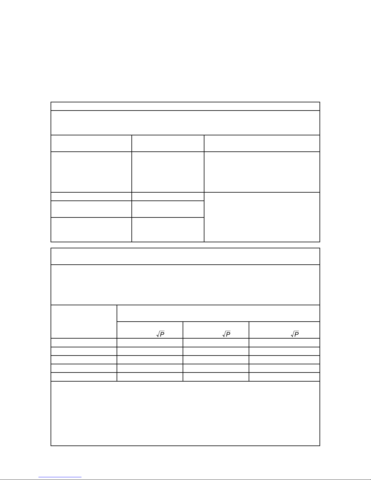
Recommended separation distances between
portable and mobile RF communications equipment and the model CL-S200
The model CL-S200 is intended for use in an electromagnetic environment in which radiated RF
disturbances are controlled. The customer or the user of the model CL-S200 can help prevent
electromagnetic interference by maintaining a minimum distance between portable and mobile
RF communications equipment (transmitters) and the model CL-S200 as recommended below,
according to the maximum output power of the communications equipment.
Rated maximum
output power of
transmitter
W
Separation distance according to frequency of transmitter
m
150 kHz to 80 MHz
d
= 1.2
80 MHz to 800 MHz
d
= 1.2
800 MHz to 2.7 GHz
d
= 2.3
0.01 0.12 0.12 0.23
0.1 0.38 0.38 0.73
1 1.2 1.2 2.3
10 3.8 3.8 7.3
100 12 12 23
For transmitters rated at a maximum output power not listed above, the recommended
separation distance
d
in meters (m) can be estimated using the equation applicable to the
frequency of the transmitter, where
P
is the maximum output power rating of the transmitter in
watts (W) according to the transmitter manufacturer.
NOTE 1 At 80 MHz and 800 MHz, the separation distance for the higher frequency range
applies.
NOTE 2 These guidelines may not apply in all situations. Electromagnetic propagation is
affected by absorption and reection from structures, objects and people.
Page 8
- 8 -
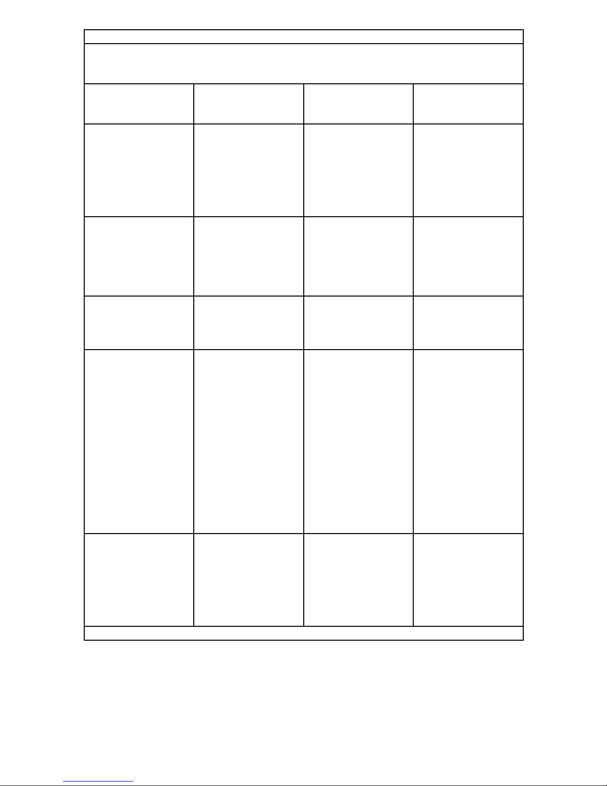
Guidance and manufacturer’s declaration – electromagnetic immunity
The model CL-S200 is intended for use in the electromagnetic environment specied below.
The customer or the user of the model CL-S200 should assure that it is used in such an
environment.
Immunity test IEC 60601 test level Compliance level Electromagnetic
environment
–guidance
Electrostatic
discharge (ESD)
IEC 61000-4-2
±8 kV contact
±15 kV air
±8 kV contact
±15 kV air
Floors should be wood,
concrete or ceramic
tile. If oors are
covered with synthetic
material, the relative
humidity should be at
least 30 %.
Electrical fast
transient/burst
IEC 61000-4-4
±2 kV for power
supply lines
±1 kV for input/output
lines at 100 kHz rate
±2 kV for power
supply lines
±1 kV for input/output
lines at 100 kHz rate
Mains power quality
should be that of a
typical commercial or
hospital environment.
Surge
IEC 61000-4-5
±1 kV line(s) to line(s)
±2 kV line(s) to earth
±1 kV line(s) to line(s)
±2 kV line(s) to earth
Mains power quality
should be that of a
typical commercial or
hospital environment.
Voltage dips, short
interruptions and
voltage variations on
power supply input
lines
IEC 61000-4-11
0 %
U
T
; 0,5 cycle
At 0, 45, 90, 135, 180,
225, 270, 315
°
0 %
U
T ;
1 cycle and 70
%
U
T
: 25/30 cycles
At 0
°
0 %
U
T
; 250/300 cycles
0 %
U
T
; 0,5 cycle
At 0, 45, 90, 135, 180,
225, 270, 315
°
0 %
U
T ;
1 cycle and 70
%
U
T
: 25/30 cycles
At 0
°
0 %
U
T
; 250/300 cycles
Mains power quality
should be that of a
typical commercial or
hospital environment. If
the user of the model
CL-S200 requires
continued operation
during power mains
interruptions, it is
recommended that the
model CL-S200 be
powered from an
uninterruptible power
supply or a battery.
Power
frequency (50/60 Hz)
magnetic eld
IEC 61000-4-8
30 A/m 30 A/m Power frequency
magnetic elds should
be at levels
characteristic of a
typical location in a
typical commercial or
hospital environment.
NOTE
U
T
is the a.c. mains voltage prior to application of the test level.
Page 9

- 9 -
Guidance and manufacturer’s declaration – electromagnetic immunity
The model CL-S200 is intended for use in the electromagnetic environment specied below.
The customer or the user of the model CL-S200 should assure that it is used in such an
environment.
Immunity IEC 60601 test level Compliance
level
Electromagnetic environment
– guidance
Portable and mobile RF
communications equipment should
be used no closer to any part of
the model CL-S200, including
cables, than the recommended
separation distance calculated
from the equation applicable to the
frequency of the transmitter.
Conducted RF
IEC 61000-4-6
3 V/m
0.15 MHz to 80 MHz
6 V/m At ISM
Frequency
3 V/m
6 V/m
Recommended separation
distance
d = 1.2
Radiated RF
IEC 61000-4-3
3 V/m
80 MHz to 2.7 GHz
3 V/m
d = 1.2
80 MHz to 800 MHz
d = 2.3
800 MHz to 2.7 GHz
where P is the maximum output
power rating of the transmitter in
watts (W) according to the
transmitter manufacturer and d is
the recommended separation
distance in meters (m).
Field strengths from xed RF
transmitters, as determined by an
electromagnetic site survey,
a
should be less than the
compliance level in each frequency
range.
b
Interference may occur in the
vicinity of equipment
marked with the
following symbol:
NOTE 1 At 80 MHz and 800 MHz, the higher frequency range applies.
NOTE 2 These guidelines may not apply in all situations. Electromagnetic propagation is
affected by absorption and reection from structures, objects and people.
a
Field strengths from xed transmitters, such as base stations for radio (cellular/cordless)
telephones and land mobile radios, amateur radio, AM and FM radio broadcast and TV
broadcast cannot be predicted theoretically with accuracy. To assess the electromagnetic
environment due to xed RF transmitters, an electromagnetic site survey should be
considered. If the measured eld strength in the location in which the model CL-S200 is used
exceeds the applicable RF compliance level above, the model CL-S200 should be observed
to verify normal operation. If abnormal performance is observed, additional measures may be
necessary, such as reorienting or relocating the model CL-S200.
b
Over the frequency range 150 kHz to 80 MHz, eld strengths should be less than 3 V/m.
Page 10

- 10 -
Label
Important
Please read the label containing warnings and cautions carefully before use.
Page 11

- 11 -
Explanation of symbols
These following symbols and labels indicate meanings as below.
Caution Mark
Indicates the monitor is approved according to
the UL & c-UL regulations
Indicates compliance to the essential
requirements of the Directive 93/42/EEC
Indicates compliance with Part 15 of the FCC
rules (Class B)
VCCI Notice (Japan Only)
Indicates the compliance to the Class B
product based on the standard of the Voluntary
Control Council for Interference (VCCI)
Indicates this apparatus must be recycled,
according to the European WEEE directive
Symbol for "MANUFACTURER"
Symbol for “AUTHORISED REPRESENTATIVE
IN THE EUROPEAN COMMUNITY“
Consult the operating instructions
AC Input
Stand-by ON/OFF
Main Power On
Main Power Off
ndicates compliance with EMC standards of
Oceania
Page 12

- 12 -
Safety precautions
This manual contains important warnings and information to prevent potential personal
injury and property damage. The symbols and signs used in this manual and their
meanings are as follows.
Symbols
Warning
Indicates a hazard which, if not avoided, could result in death or
serious injury.
Caution
Indicates a hazard which, if not avoided, could result in minor or
moderate personal injury or property damage.
Meanings
Calls your attention to warnings or cautions. This sign may contain a
picture of a specic situation. E.g.)
risk of electric shock
Indicates a banned action. This sign may contain a picture of a specic
situation. E.g.)
no disassembly
Indicates you must follow the instructions. This sign may contain a
picture of a specic situation. E.g.)
Unplug from the wall outlet
Other signs
Important
Contains very important information. Make sure to read it before use.
Note
Contains do's and don'ts.
Provides helpful information.
Indicates reference.
Page 13

- 13 -
Warning
Do not disassemble, repair, or alter the monitor. It could cause re, electric
shock, or injury. Servicing of such a monitor may be refused. Or a fee may
be charged even within the warranty period. Ask your dealer for repairs.
Do not continue using the monitor when failure or abnormality is found. It
could cause re or electric shock.
Do not touch or swallow the liquid crystal that may leak from the damaged
panel. It could cause skin irritation. If it gets into the eye, ush the eye with
water and call your doctor. If it adheres to skin or clothes, wash it off
immediately with water. It contains a stimulating substance.
Do not put anything on top of or over the monitor. It could cause the monitor
to fail or cause re.
Do not put anything over the cables. It could cause the monitor to fail or
cause re.
Do not handle the monitor with wet hands. It could cause the monitor to fail
or cause electric shock.
If smoke or odor is observed, turn off and unplug the monitor immediately.
Continual use could cause re or electric shock. Consult your dealer.
If by accident you drop the monitor or give it a jolt, turn off and unplug the
monitor immediately. Continual use could cause re or electric shock.
Consult your dealer.
If liquid or any foreign object enters inside, turn off and unplug the monitor
immediately. Continual use could cause re or electric shock. Consult your
dealer.
To avoid a lighting strike, stop using the monitor during thunder. It could
result in electric shock.
Make sure to use the supplied power cable. The use of a cable other than
supplied could cause the monitor to fail.
The input voltage for this monitor is limited to AC 100 V to AC 240 V. Do not
use it at any other voltage. Failure to do so could cause the monitor to fail or
cause re.
The monitor must be grounded. Failure to do so could cause electric shock.
When using a 2P plug, ground the monitor before plugging into a wall outlet.
To remove the grounding cable, unplug the monitor rst.
Page 14

- 14 -
Follow the instructions below in handling the power plug.
• Hold the plug when unplugging. Pulling the cord could cause damage and
result in re or electric shock.
• Do not plug/unplug with wet hands. It could cause electric re.
• Dust the plug periodically and keep it dust-free to avoid re or electric
shock.
• Do not overload wall outlets. It could cause re or electric shock.
• Do not put things around the monitor. Keep enough space around for easy
access to the plug.
Turn off and unplug the monitor and its peripheral devices when installing,
uninstalling, and/or moving the monitor.
This monitor and its components come in plastic bags. Keep out of reach of
children. Playing with plastic bags could cause suffocation.
Caution
Install the monitor indoors. It is not designed for the use outdoors or aboard
vehicles.
Do not put the monitor in a stuffy, dusty, humid place. Do not expose it to oily
smoke or steam. It could cause the monitor to fail and cause re or electric
shock.
Do not put the monitor on an unstable surface. It could cause the monitor to
fall and result in injury.
Do not expose the monitor to direct sunlight. It could damage the cabinet or
other parts and result in overheat or re.
Avoid a place subject to
• Magnetic elds • Vibrations
• Corrosive gases • Electrostatic charge
It could cause the monitor to fail.
Do not use the monitor with condensation on the surface. It could cause the
monitor to fail. Condensation forms when the monitor is moved into a warm
room from a cold place. Let it sit until it goes away.
Do not place the monitor on its back or use in a place with little ventilation.
Heat could build up and damage the cabinet and/or the inner parts. It could
result in shortening of life, overheat, and/or re.
Rest your eyes for 10 to 15 minutes per hour. Failure to do so could cause
eyestrain.
Page 15

- 15 -
Disconnect the power cord if abnormalities such as smoke and re, etc. are
observed. Do not position the monitor so that it is difcult to operate the
disconnection.
LCD
Even if it is used properly, the monitor may cause harmful interference to
radio or television reception. Try the following measures to correct it.
• Increase the distance between the monitor and the radio/TV.
• Connect the monitor into a different outlet from the one to which the radio/
TV is connected.
Do not press, scratch, or put objects on the LCD panel surface. It could
cause monitor noise and/or cause the panel to fail.
Do not monitor a static image for too long. It could cause "ghosting," a
phenomenon where the previous image displayed on the screen is seen for
moments after the image has changed.
Turn on a screensaver or enable the standby mode to avoid "burning in," the
burning of an image onto the LCD panel after hours of the same image
being displayed.
Please be advised that the following symptoms may occur due to the nature
of LCDs. They are not failures.
• During use in cold environments, "streaking" may occur or images may
appear dark.
• Depending on use conditions such as temperature, spots or unevenness in
luminance or color may be observed.
• Due to the manufacturing technology used, there may be pixel or dot
failures even though its rate of effective pixels is 99.999301 %.
Do not set maximum luminance or closer to it when using the monitor in a
dim room below 100 lx. It could cause eyestrain. We recommend the factory
default. Setting it too low could makes it hard to see the image.
Do not push or give a shock to the LCD luminance sensor. It could cause the
set luminance level to change and/or the LCD to fail.
LCD luminance sensor
Clean inside of the monitor once a year. The dust could cause re.
Ask your dealer for maintenance.
Page 16

- 16 -
Features
● 21.3" UXGA high-denition Color LCD panel
A 21.3" (diagonal 54 cm) LCD panel provides clear display of images high resolution of
UXGA (1600 x 1200).
● Daisy-chain via DisplayPort
Implemented DisplayPort with 10 bit depth color in addition to DVI input and achieved
1billion 73 million simultaneous color with 10 bit input. By connecting monitors through
DisplayPort in daisy-chain, it gets much easier to organize wires.
● High luminance, high contrast and LED backlight
The LCD panel has a maximum luminance of 1000 cd/m
2
typ., a contrast ratio of 1800:1
typ., and a super-wide viewing angle of 178° typ. (contrast ratio ≥ 10:1) horizontal and
vertical. Realized the power saving by the LED backlight.
● Luminance Uniformity correction feature
CL-S200 has Uniformity correction function to provide uniformity of color/luminance.
Corrects luminance unevenness or color unevenness, which arising from the LCD panel.
This function enables monitors to be used in pairs without peculiarity among any
monitors.
● Luminance stabilizer λ-Sentinel
Our unique built-in luminance stabilizing circuit λ-Sentinel provides stable luminance for
a long period of time.
● Pivoting capability
The LCD panel can also be used in portrait orientation. Hardware-based pivoting is, unlike
graphics card- or software-dependent pivoting, much faster with less noise.
● Interchangeable stand
The tilt stand is interchangeable with an arm stand with a mount that has a 4-hole pattern
at 100 mm x 100 mm according to your needs and preferences.
● Automatic detection of the monitor orientation with gravitation sensor
With the implementation of the gravitation sensor, automatic EDID setting, OSD direction
change and screen rotation less than XGA (1024 x 768 resolution) have been achieved.
● Dynamic gamma function
Automatically distinguishes the images on the screen between monochrome and color,
and displays the respective images with the most suitable grayscale.
● Auto text mode function
Automatically decreases luminance of the text window (white) when it is shown to help
reduce eyestrain.
● Human presence sensor
Activates “Human presence sensor” function, when leaving your seat, states of the
monitor automatically switches into “Standby.” It leads to reduce power consumption.
Page 17

- 17 -
Names and functions of parts
1
432 5 6
①
Human presence sensor
When leaving your seat, the status of the monitor automatically switches into
“Standby” due to “Human presence sensor.”
②
Operation button
Displaying Menu on OSD or conguration can be available by these four buttons.
③
Stand-by button
_
When the main power ⑬ is “ON”, this button is available.
Note
Wait at least 5 seconds between on/off actions.
④
LED Indicator
No. LED Power Mode
1 Off Off Power off
2 Off On Normal (Luminance stabilized)
3 Green On Luminance stabilizer on
4 Blinking green On Calibrating
5 Orange On Power management on
6
Blinking orange
at intervals of 1
seconds
On Advanced power management on
7
Blinking orange
at intervals of 0.5
seconds
On
With luminance uctuation (If you
have a blinking orange LED, please
consult your dealer.)
8 Blinking red On Error (Please consult your dealer.)
Page 18

- 18 -
13121110
987
⑤
LCD Luminance Sensor
Do not push or give a shock to the LCD luminance sensor. It may cause the set
luminance level to change and/or the LCD to fail.
Caution
⑥
Ambient Light Sensor
⑦
DVI-D: Digital video signal input port. Connect the supplied DVI cable.
⑧
DisplayPort OUT: Digital video signal output port. Use DisplayPort cables when
connecting monitors in daisy- chain.
⑨
DisplayPort IN: Digital video signal input port. Connect a DisplayPort cable.
⑩
UP: USB upstream port. When connecting a USB device to DOWN (above), connect
one end of the supplied USB cable to the monitor's UP and the other end to the
computer's USB port.
⑪
DOWN: USB downstream ports (x2). A USB device with a maximum current
consumption of 500 mA per port can be connected to each port. Multiple CL-S200
monitors, connected in a daisy chain, can be calibrated in succession by connecting
the supplied USB cable between here and the next monitor’s UP.
⑫
AC Inlet: Connect the supplied Power cord.
⑬
Main power switch: Main power supply switch.
Page 19

- 19 -
Reference
Power save function
The monitor enters into power save mode after idling for a certain period of time to reduce
power consumption. Refer to the computer instruction manual on how to set it.
Digital input
This monitor supports only DVI digital signal. It is normal for noise to occur during
startup, shutdown, and/or at switching resolutions. This is caused by the graphics card in
the system as it switches resolution. Also, when switching resolutions, a 5 sq. mm white
area may appear under the front sensor. In both cases, they are not failures.
Note
Turn off the system when connecting and disconnecting the DVI cable. It could
damage the graphics card.
Operating Principle
Image signals from acquisition devices or picture-archiving communication system (PC)
shall be transmitted to the monitor via DVI or DisplayPort terminals.
By transmitting image signals of the system to the input unit of the monitor, the monitor
can provide images on its screen (LCD panel) via its signal processing circuit. It is
possible for users to congure the monitor freely for suitable observation by OSD
because of the input unit and the signal processing circuit which correspond to various
input signals.
Input unit
Signal
processing
circuit
Power unit
Operation unit
LCD Module
Page 20

- 20 -
Cleaning kit
Cleaning the monitor
● When cleaning the monitor, remove the Power cord from the monitor and the wall
outlet for your safety.
● Wipe off dust on the cabinet with a soft cloth. Dampen it lightly in mild soap solution to
wipe off grease. When using a disposable cloth, follow the instructions.
● The cabinet is made of plastic and coated metal plate. Do not apply thinner, benzene,
or alcohol. It could damage the plastic and/or the coating could come off.
● Do not spray insecticides and other volatile solutions on the cabinet. Do not keep
rubber or vinyl in contact with the cabinet for a long time. It could damage the cabinet
and/or the coating could come off.
● An optional cleaning kit* is recommended to clean the panel surface.
Dampen the cleaning cloth with the agent and remove the dust
gently. Finish up by wiping with the dry cloth.
Commercially available cleaners or mildly alkaline detergents could
damage the AR coating.
*: Optionally, we will be preparing cleaning kit. Ask your dealer
for more information.
● Be careful when handling the LCD panel. Do not rub or hit with sharp or hard objects.
Do not press on the panel. It could cause unevenness in luminance or damage the
panel.
Page 21

- 21 -
Connector pin assignment
DVI 24-pin (female) connector for DVI signals
Pin # Signal Pin # Signal
1 TMDS Data 2- 13
2 TMDS Data 2+ 14 +5V Power
3 TMDS Data 2 Shield 15 GND
4 16 Hot Plug Detect
5 17 TMDS Data 06 DDC Clock 18 TMDS Data 0+
7 DDC Data 19 TMDS Data 0 Shield
8 20
9 TMDS Data 1- 21
10 TMDS Data 1+ 22 TMDS Clock Shield
11 TMDS Data 1 Shield 23 TMDS Clock+
12 24 TMDS Clock-
DisplayPort receptacle connector
Pin # Signal Pin # Signal
1 ML_Lane 3(n) 2 GND
3 ML_Lane 3(p) 4 ML_Lane 2(n)
5 GND 6 ML_Lane 2(p)
7 ML_Lane 1(n) 8 GND
9 ML_Lane 1(p) 10 ML_Lane 0(n)
11 GND 12 ML_Lane 0(p)
13 CONFIG1 14 CONFIG2
15 AUX CH(p) 16 GND
17 AUX CH(n) 18 Hot Plug Detect
19 Return 20 DP_PWR
USB B type receptacle connector (UP)
Pin # Signal
1 VCC
2 -DATA
3 +DATA
4 GND
USB A type receptacle connector (DOWN)
Pin # Signal
1 VCC
2 -DATA
3 +DATA
4 GND
1
8
24
17
2
1
4
3
14
19
1
2
20
DVI-D
DisplayPort IN
/ DisplayPort OUT
Page 22

- 22 -
Use CL-S200 in the room that its ambient light is less than TBD lx.
Specications are subject to change without notice.
Technical specication
Item CL-S200
LCD 21.3-inch (54 cm), color, TFT, Anti-glare, IPS
Pixel pitch (H x V) 0.270 x 0.270 mm
Display area (H x V) 324.0 x 432.0 mm (Portrait)
Pixel (H x V) 1200 x 1600 (Portrait)
Display colors
8 bit:16.77 million out of 281 trillion*
10 bit: 1.073 billion out of 281 trillion* *1 trillion = 10
12
Backlight LED backlight
LCD Optical
characteristics (typ.)
Viewing angle: 178° horizontal and vertical (Contrast ratio ≥ 10:1)
Contrast ratio: 1800:1 (Viewing angle of 0° horizontal and vertical)
Maximum luminance 1000 cd/m
2
Luminance
DICOM calibrated
(Gamma setting to DICOM, Chromaticity: x0.308, y0.309)
Factory default 500 cd/m
2
Input sync signal DVI 1.0 compliant, DisplayPort 1.2a compliant
Available resolution
US Text, 640 x 480*, 800 x 600*, 1024 x 768*, 1280 x 1024*,
1200 x 1600*, 1600 x 1200* (*: at Fv=60 Hz only)
Input terminal DVI 24-pin connector, DisplayPort IN connector
Output terminal DisplayPort OUT connector
USB Hub
USB Rev. 2.0 compliant, Self-powered
USB upstream port (x1), USB downstream ports (x2)
Environmental
Conditions
Operating Transport/Storage
Temperature : 5 to 35 °C* -20 to 60 °C
(41 to 95 °F* -4 to 140 °F)
Humidity (no condensation) : 30 to 80 % 10 to 85 %**
Air pressure : 700 to 1060 hPa 266 to 1060 hPa
* Operating temperature range that ensures optimal performance
of the monitor is 20 to 30 °C (68 to 86 °F.)
** Wet-bulb temperature Max. 38 °C (100.4 °F)
[Ta> 40 °C (104° F)]
Power 100-240 V
2.2 - 1.1 A 50/60 Hz
Dimensions
(W x H x D)
Net: 361.5 × 517/612 × 196.5 mm (Portrait)
493 × 451.3/546.3 × 196.5 mm (Landscape)
Packed: 585 × 580 × 285 mm
weight (approx.) Net: 9.2 kg (Without stand 6.2 kg), Packed: 12 kg
Calibration kit
(Optional)
Calibration sensor and software
Conformities
ANSI/AAMI ES60601-1 (2005)+A1 (2012),
CAN/CSA-C22.2 No.60601-1 (2014), FCC-B, ICES-003-B,
FDA510(k), CE, VCCI-B, RoHS, J-Moss
Page 23

- 23 -
External dimensions
Portrait (vertical orientation)
196.5
ᨺ
34.5
80.5
4.3
166.5
+20°
-5°
95
361.5
493
240
11.5
ᨺ
326.5
434.5
ᨺ
493
361.5
434.5
326.5
ᨺ
Landscape (horizontal orientation)
Unit: mm
Page 24

- 24 -
After-sales service
Warranty
Consult your dealer about the warranty.
Requesting repair
• Read "When a failure is suspected... " carefully and check if the problem solves.
• If the problem remains, stop using the monitor, unplug it, and consult your dealer. Do
not try to repair yourself.
• In-warranty repair:
Depending on the problem and usage, it will be repaired free of charge.
• Out-of-warranty repair:
Consult your dealer. Depending on the problem, repair service may be available for a
fee upon request.
• Use the original box and packing material to pack the product for shipping. Make sure
that the LCD panel does not come in contact with the packing material when packed. It
could damage the panel. We are not liable for such damage.
Please provide the following information when contacting your dealer:
• Model name
• Serial number
• Date of purchase
• Detailed description of the problem
Technical support
Contact your dealer for technical support.
Recycling the monitor
Do not dispose of LCD monitors as solid waste (along with domestic waste). The related
national/local laws and regulations may apply. Consult your dealer for more information.
Page 25

- 25 -
Disposal of Electrical and Electronic
Equipment
Information on Disposal of Old Electrical and Electronic Equipment and
Batteries (applicable for countries that have adopted separate waste
collection systems)
Products and batteries with the symbol (crossed-out wheeled bin) cannot be
disposed as household waste.
Old electrical and electronic equipment and batteries should be recycled at a
facility capable of handling these items and their waste byproducts.
Contact your local authority for details in locating a recycle facility nearest to
you.
Proper recycling and waste disposal will help conserve resources whilst
preventing detrimental effects on our health and the environment.
Notice: The sign “Pb” below the symbol for batteries indicates that this
battery contains lead.
Page 26

- 26 -
This page is intentionally left blank.
Page 27

- 27 -
Notes for the Instruction Manual
• No part of this manual, whether partly or wholly, may be reproduced or copied without authorization.
• The content of this manual is subject to change without notice.
• Although this manual has been prepared carefully, please let us know if you nd any errors,
omissions, or ambiguous explanations.
CL-S200 Operation Manual
October 2017 Edition PZZ11-2499
Page 28

Printed in Japan
© 2017 JVCKENWOOD Corporation
B5A-2228-00
3-12, Moriya-cho, Kanagawa-ku, Yokohama-shi, Kanagawa 221-0022, JAPAN
171012
 Loading...