

Page 1
Page 2
Removal of Main Parts
Disassembling Procedures
Perform operations according to the items to be disassembled.
Replacement of the Pickup
1. After removing the exterior (top and bottom)...
2. Proceed to the "Pickup Replacement" section.
3. When applying grease, refer to the Exploded View.
Use new grease.
Mechanism Section
1. Remove the exterior (required section only).
2. The mechanism section is designed so that each unit can be
removed separately.
3. When re-assembling, refer to the assembling precautions.
(Use new grease when applying grease.)
*Exterior Section
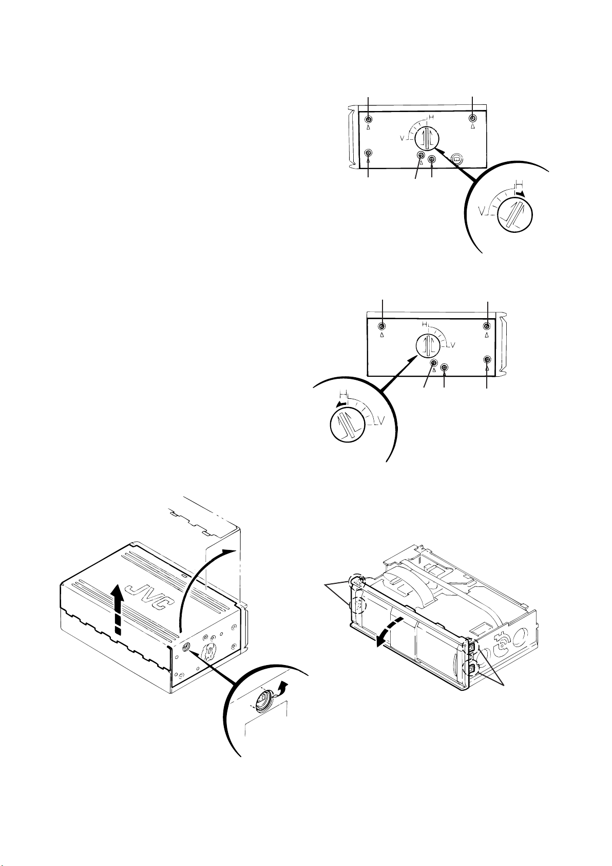
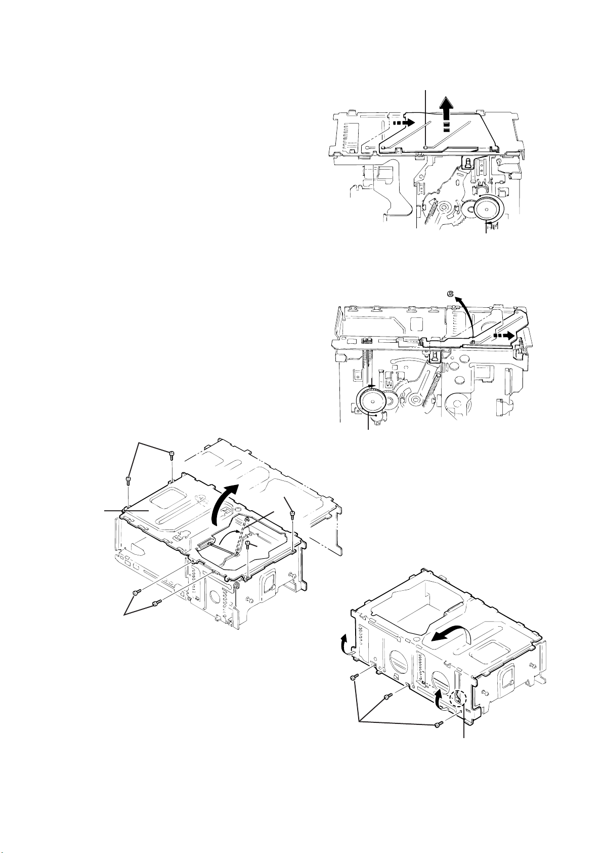
Removing the Bottom Cover and Front Panel
Assembly
1. Remove the screw (1-a) to unlock the mounting direction
knob located on the side of the main unit.
2. Turn the mounting direction knob in the direction of the arrow
using a coin, etc. to remove it. (The knob can be removed
only when it is set to this position.)
3. Remove the four top cover fixing screws (1) at the triangle
(A) marks on the side of the main unit. (Perform the same
operation on both sides.)
4. Turn the unit upside down so the bottom surface is facing
upward.
5. Lift the rear edge of the bottom cover slightly and lift the side
by grasping the DIN jack section on the side panel, then
turn it toward the front (raise upward) to remove the bottom
cover.
6. Unhook the four catches located on both sides of the front
panel, and turn the front panel toward the top cover (lower
down) to remove the front panel.
1 1
1
Remove 1-a and
turn in the
direction of the
arrow
1
1-a
Fig. 1
1 1
Fig. 2
Remove 1-a and
turn in the direction
of the arrow.
111-a
The front panel can be
separated by raising the
cover.
Fig. 3
Unhook catches
Unhook catches
Fig. 4
Slightly lift the
jack section to
remove.
Page 3
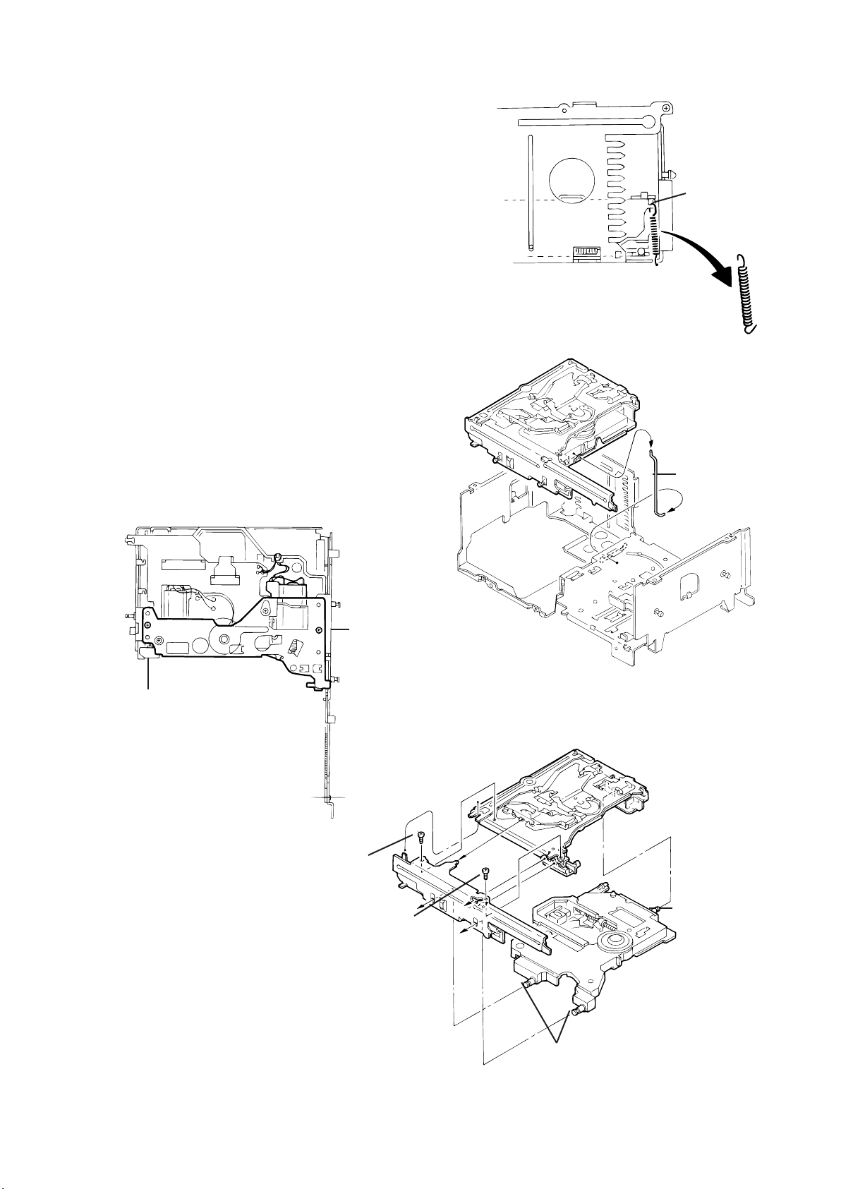
Removing the Top Cover
1. Remove the four damper bracket fixing screws (2) to remove
the damper brackets.
2. Pull out the dampers, being careful not to damage them.
When re-attaching a damper, insert your finger to push out the
center of the damper to mount it on the damper shaft, as
shown in Fig. 6-1.
3. Turn the damper spring bracket toward the top at a right angle
as shown in Fig. 7, then push down the lower side of the
damper spring bracket to lift it off.
4. Remove the three fixing screws (3) and (4) on the DIN jack
PCB assembly.
5. Lift the changer unit upward.
6. Remove the damper springs from the mechanism chassis if
required. To reassemble, refer to the diagram below.
Apply alcohol to the shaft then
immediately attach the damper. (After
attaching, check that the shaft is
correctly inserted.)
Fig. 5
2
2
Fig. 6-1
Lift the changer unit upward
Fig. 8
Push out with your
finger before
attaching
2
2
Turn to the top position (at a right angle),
Remove the flexible ribbon
wire if required
Fig 6
then push down to lift off.
Fig. 7
4
4
Mechanism
Chassis
Silver
(mechanism side)
How to Attach the Damper Springs
Fig. 8-1
Black
(magazine side)
3
Fig. 9
Page 4

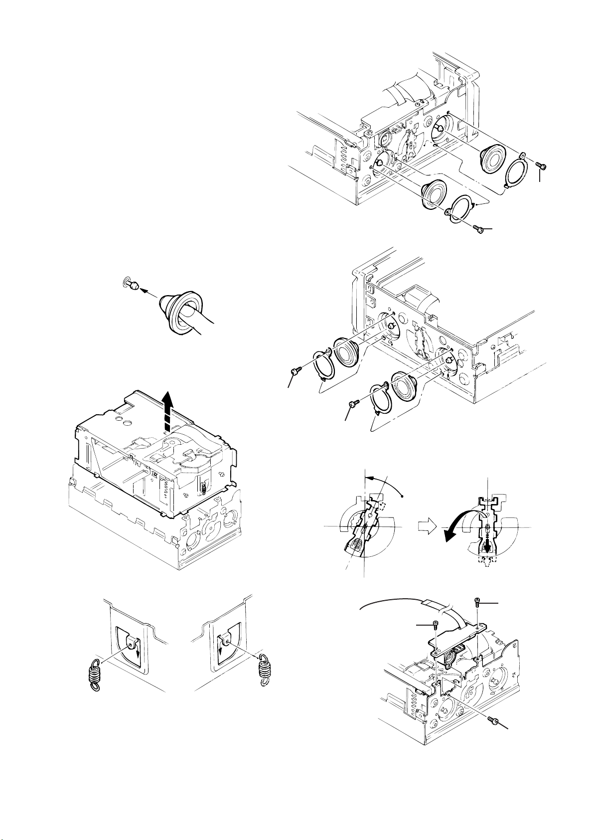
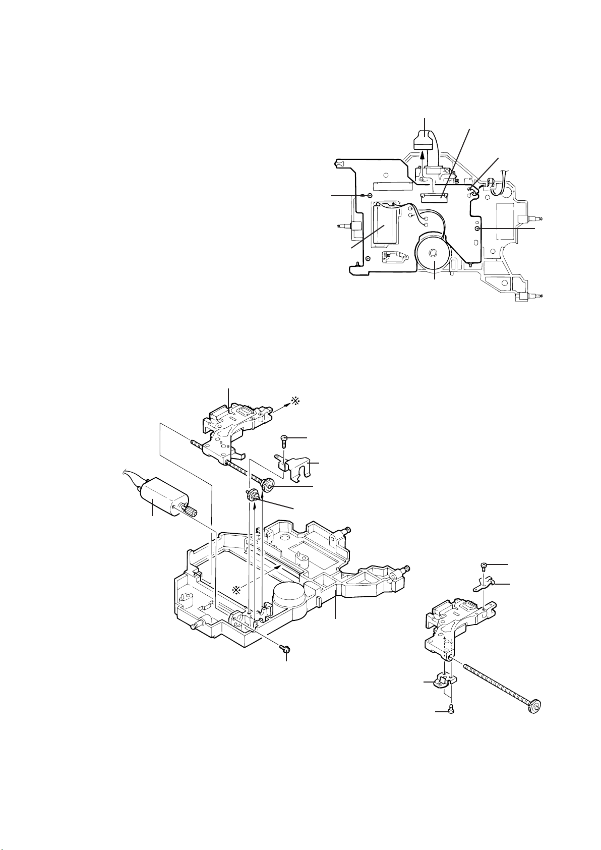
Removing the Fittings
1. Remove the fixing screw (5).
2. Unhook the two catches (a) on the top edge of the fitting,
then unhook the catches (b) at the left/right bottom edges.
Catches (a)
Catches (b)
Fitting
Removing the Main PCB Assembly
1. Remove the power IC fixing screw (6).
2. Remove the four screws (7) securing the main PCB
assembly.
3. Disconnect position motor wire connector CN504 from the
main PCB assembly.
4. Disconnect sensor PCB assembly wire connector CN601
from the main PCB assembly.
5. Remove the flexible ribbon wire from CN502 on the traverse
mechanism PCB assembly.
When re-installing the PC boards, refer to the reassembling
procedures for protecting switches, etc.
CN502
7 CN601
5
Fig. 10
7
7
Fig. 11
CN504
6
Page 5
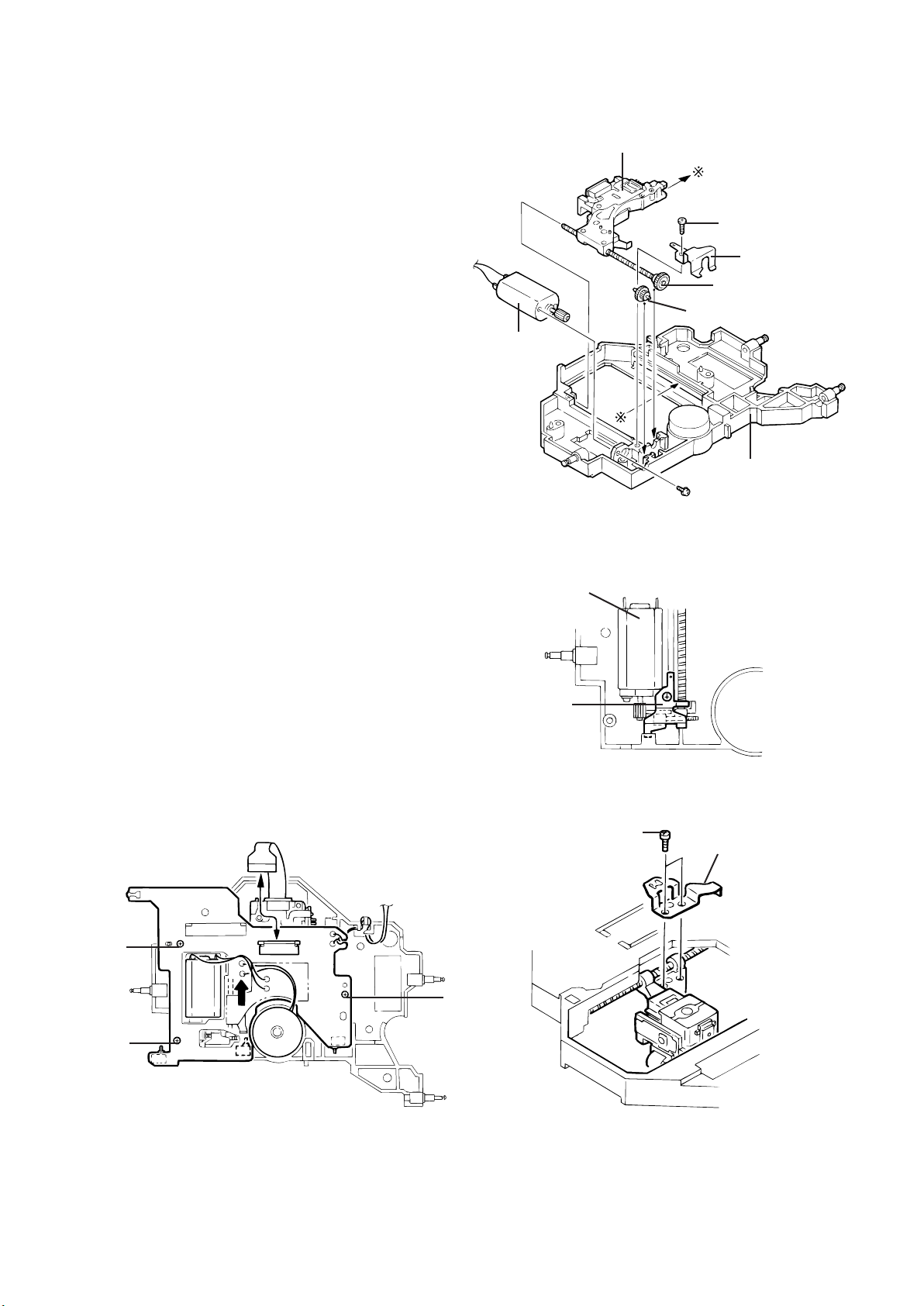
*Changer Mechanism Section
Sensor Assembly Unit
1. Remove the two screws (1) securing the sensor assembly
unit.
2. Unhook the springs on the back of the sensor assembly unit
from the holes on the chassis.
1
Sensor
Assembly
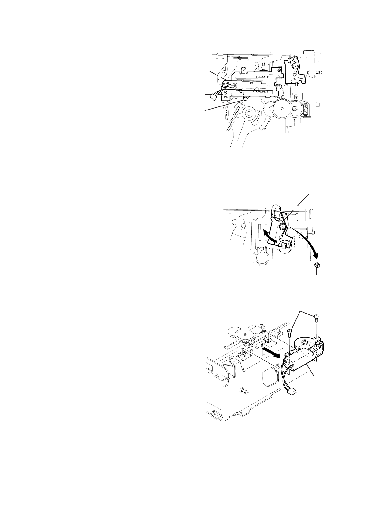
Magazine Lock Arm
1. Remove the magazine lock spring from the front side of the
chassis.
2. Remove the poly-washer (b) securing the magazine lock arm.
3. Turn the magazine lock arm in the direction of the arrow until
the notch is at the "C" position to remove it from the chassis.
Positioning Motor Assembly
1. Remove the two screws (2) securing the positioning motor.
2. Slightly lift the positioning motor assembly to remove it from
the two burrs on the chassis.
1
a
Fig. 14
Magazine Lock Spring
Rear
c
Fig. 15
Poly-Washer (b)
Fig. 16
2
Positioning
Motor Assembly
Page 6
Rear Slider
1. Position the unit with the front section facing down. Rotate
the third gear located on the back of the main unit in the
direction of the arrow (clockwise).
2. Shift the rear slider in the direction of the arrow and remove it
at the rear slider mounting position (at the widest hole).
Front Slider
1. Position the unit with the rear section facing down. Rotate the
third gear located on the bottom of the unit in the direction of
the arrow (clockwise) until the front slider is shifted to the
outermost position.
2. Remove the E-washer securing the front slider to remove the
front slider from the chassis.
Can be removed at the stud position
(at the widest hole)
Shift
Fig. 17
Remove
Third Gear
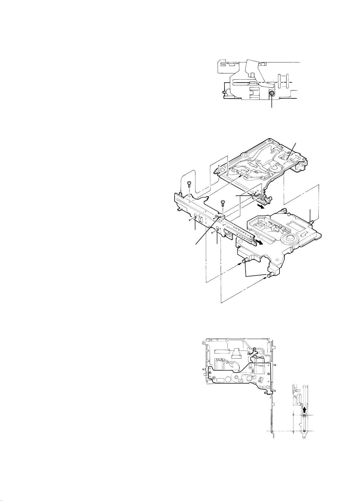
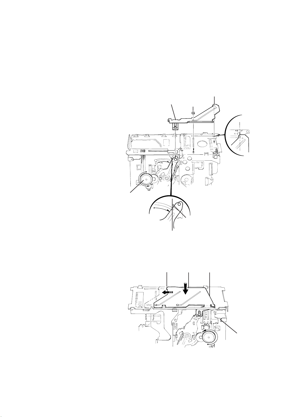
Top Plate
1. Remove the nine screws (3) securing the top plate.
2. Disconnect the section (e) attached to the rear of the unit,
then lift the top plate slightly.
3. Slide the top plate toward the rear of the unit to remove the
upper rod from the top plate.
3
Slide
3
Top Plate
Rod
3
Remove the E-washer
Third gear
Slide and remove the rod inside
Fig. 18
3
Remove
Fig. 19
After Lifting
3
e
Fig. 20
Page 7
Lifter Unit
1. Unhook the elevator spring located on the front side of the
unit.
(Be sure to first unhook the spring from the lifter side as
shown in the upper part of the diagram.)
2. Lift the lifter unit upward, then remove the lower rod to
remove the lifter unit from the chassis.
Lifter Bracket
1. Remove the two lifter bracket fixing screws (4) located on the
back of the lifter unit.
2. Remove the lower rod.
Side Bracket and Traverse Mechanism
1. Remove the two side bracket unit fixing screws (5) to
disconnect the side bracket unit from the lifter unit.
2. Remove the three shafts on the traverse mechanism
assembly from the lifter unit.
For reassembling, refer to the reassembling
procedures.
Fig. 21
Unhook this
part first
Proper
orientation
Lift up the lifter unit
Lower Rod
4
Fig. 22
4
Fig. 23
5
Remove from the
5
lifter unit
Fig. 24
Remove from the
lifter unit
Page 8
Pickup Assembly
1. Remove the three mechanism PCB fixing screws (6) located
on the back of the traverse mechanism.
2. Disconnect the two feed motor wires (blue and white), two
spindle motor wires (red and black) and two tray motor
wires (brown and black) that are soldered to the mechanism
PCB assembly.
3. Short-circuit the grounding point on the mechanism PCB
assembly, and lift it with the flexible PCB attached to
connector CN501.
Next, short-circuit the grounding point on the pickup unit
and disconnect CN501.
4. Remove the screw (7) to remove the feed motor assembly.
5. Remove the screw (8) to remove the shaft holder retaining
the feed slide shaft assembly and the middle gear.
6. Remove the middle gear.
7. Move the pickup assembly upward from the gear section
and remove it from the traverse chassis assembly.
8. Remove the two screws (9) to remove the rack arm.
9. Pull out the feed slide shaft assembly.
10. Remove the screw (10) to remove the spring.
Note: Before replacing the pickup, be sure to short-circuit the
grounding points. First short-circuit the PCB section and
then immediately short-circuit the pickup section.
Pickup: Remove
after shorting
6
Feed Motor
Pickup Flexible PCB
CN501
Tray Motor Wire
6
Spindle Motor
Grounding Point
Fig. 25
Grounding Point
Feed Motor
Remove gears and
motors only when
required.
Fig. 26
Pickup Assembly
Middle Gear
7
8
Shaft Holder
Feed Slide Shaft Assembly
10
Chassis
Pull out
Rack Arm
9
Fig. 27
Page 9
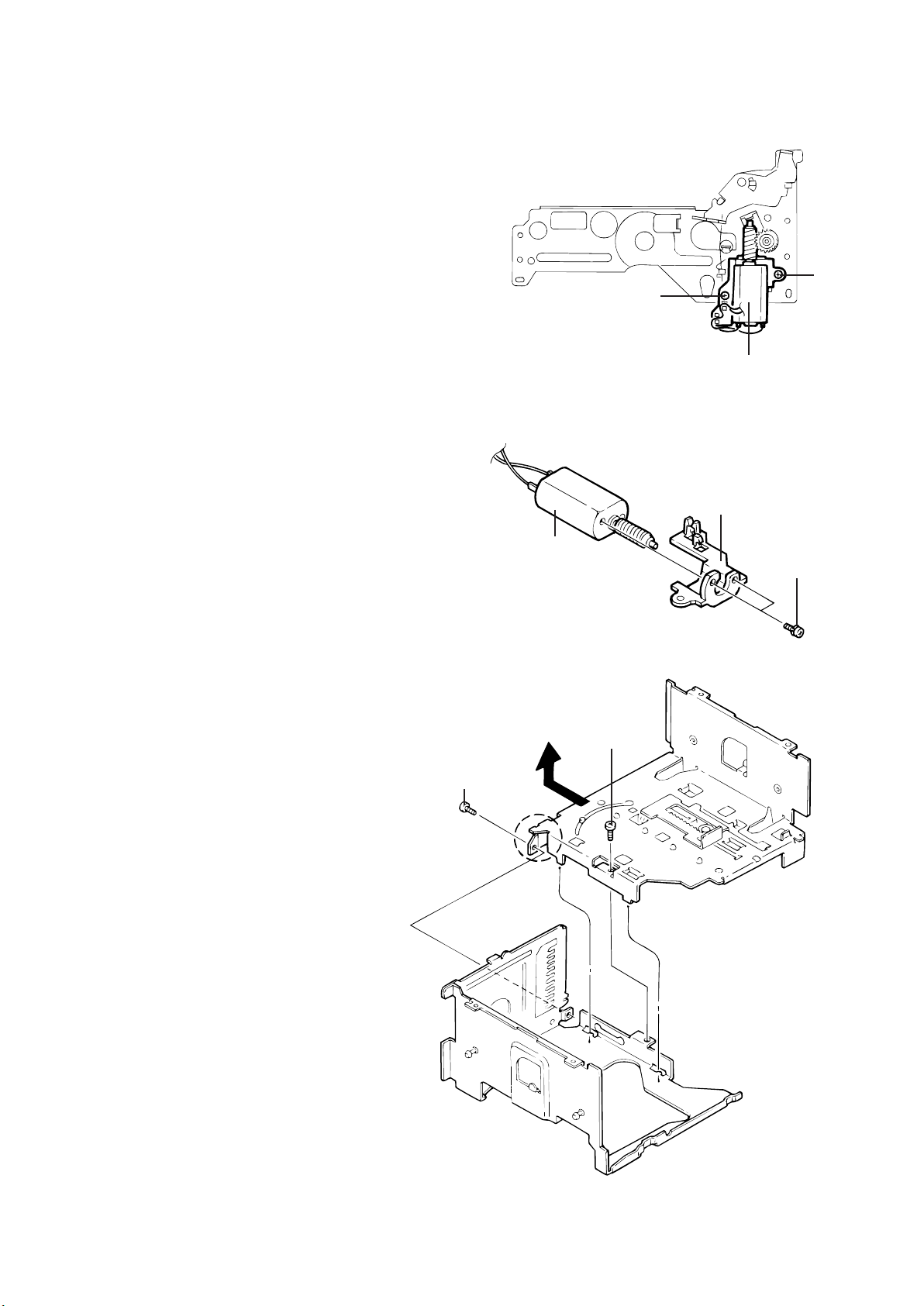
Tray Motor
1. Remove the two screws (11) securing the tray motor.
2. Remove the two screws (12) to remove the tray motor
assembly from the tray motor holder.
Separation of the Chassis L Assembly and
Chassis R Assembly
1. Remove the two screws (13) retaining the chassis "L" and
"R" assemblies.
2. Slide the chassis L assembly toward the front and detach it,
then remove the chassis "L" upward.
11
11
Fig. 28
Tray Motor
Slide and remove upward as
shown by the arrow
13
Tray Motor Assembly
Tray Motor Holder
12
Fig. 29
13
Front side
Fig. 30.
Page 10
Precautions On Reassembling
When reassembling, also refer to the
disassembling procedures.
Pickup Assembly
Mounting the Traverse Mechanism
1. When mounting the pickup assembly, attach the feed slide
shaft assembly to the traverse chassis.
Apply E-JC-525 grease to the shaft.
2. Mount the middle gear and the feed slide shaft to the traverse
chassis and secure them with the screw (14) through the
shaft holder.
3. Before mounting the mechanism PCB assembly, move the
pickup to the outer edge position, then secure the PCB
assembly using the screw (15).
At this time, check that the rest switch is correctly placed.
4. To mount the rack arm, first move the pickup to the middle
position and secure it with the screws (16).
Motor
Feed Motor
Fig. 31
Attached to chassis
14
Shaft Holder
Feed Slide Shaft (half
coated with grease)
Middle Gear
Chassis
Mounting the
Feed Motor Assembly
Mechanism PCB Assembly
15
15
Fig. 33
15
Shaft Holder
Spindle Motor
Fig. 32
16
Rack Arm
Move the pickup to the
middle position
Fig. 34
Page 11
Mounting the Lifter unit
1. Insert the shafts (B) of the traverse mechanism assembly into
the slide grooves (F) on the lifter unit.
2. Shift the hook of the lifter unit to the edge, and shift the
sliding lever inside the side bracket unit to the edge as well.
3. With each hole and lever shifted to the edge, mount the lifter
unit and side bracket unit from the side.
(Check each attached section, and check that the two shafts
(C) of the lifter unit are correctly inserted into the holes (g) of
the side bracket unit. After mounting, check that the levers
move together. )
4. Turn the lifter unit upside down.
As shown in Fig. 37, slide the lever 30 mm away from the
edge, then mount the lifter bracket L assembly.
Attach
(C)
Fig. 35
(B)
(F)
(B)
(F)
(g)
(F)
(B)
Fig. 36
Fig. 37
Shift inside by approx. 30 mm
Expanded View
Page 12
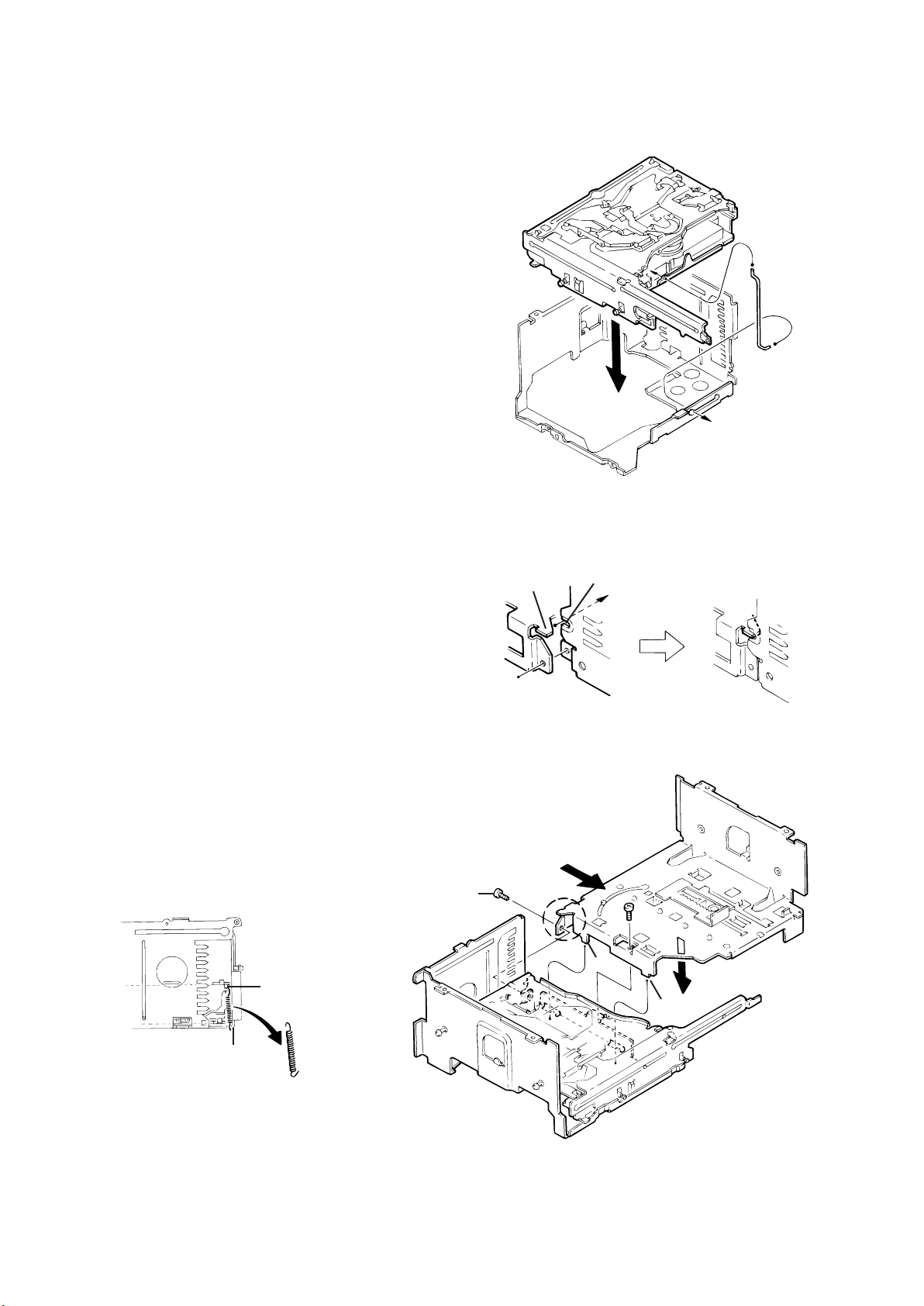
Connection of the Chassis "L" Assembly
and Chassis "R" Assembly
1. Attach the lower rod to the chassis "R" assembly. While
shifting the rod toward the front side, mount the rod on the
lifter unit.
With the rod mounted, place the lifter unit on the chassis "R"
assembly.
2. Combine the chassis "L" and "R" assemblies so that the hook
section (h) of the chassis "L" assembly is inserted into the
notch of the chassis "R" assembly by sliding it from the front
side.
3. After engaging, secure with the two screws (18).
4. Attach the tension spring between the lifter unit and the
chassis.
Lower Rod
Fig. 38
Set last (lifter side)
18
h
Slide to engage
Notch
Attached
Fig. 39
i
Combine with R chassis
i
Set first
(chassis side)
Tension Spring
Proper
orientation
Fig. 40
Page 13
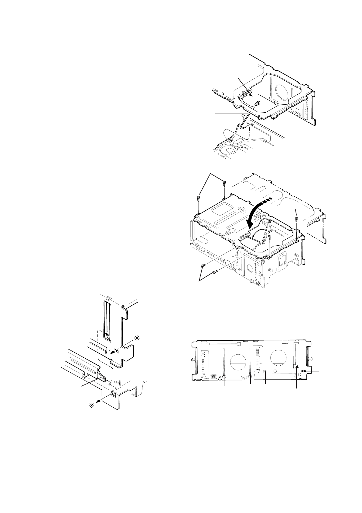
Mounting the Top Plate
1. Mount the upper rod on the lifter side (j) and set it on the rear
of the top plate, then mount the other end of the upper rod to
(k).
2. Check that the five points (l, m, n, o and p) are correctly
positioned.
When mounting section (q), set it so that section (D) of the
lifter unit is pinched by the bending section of the top plate.
3. Secure the top plate with six fixing screws (19).
k
Upper Rod
Fig. 41
19
19
Expanded view of mounting "q"
(D)
Lifter Unit
Section "p"
Fig. 43
19
Fig. 42
p
l
m n
q
Fig. 44
Page 14
Mounting the Front Slider and Rear Slider
1. Position the unit with the rear side facing down, then rotate
the third gear in the direction of the arrow (clockwise) until the
lift arm comes to the position at which the holes are exposed,
as shown in Fig. 45-1.
2. Mount the front slider from the top.
Rotate the third gear counterclockwise until the hole of the
slider is lined up with the right hole of the stud, as shown in
Fig. 45-2.
3. Mount the E-washer on the shaft.
4. Position the unit with the front side facing down, then mount
the rear slider. Check that the (r), (s) and (t) positions are
correctly mounted as shown in Fig. 46.
5. Rotate the third gear in the direction of the arrow
(counterclockwise) until the lifter unit is at the top position.
Check after mounting
Front Slider
E-Washer
Stud
Position so that the
stud and right hole
are lined up
Fig. 45-2
Rotate the third gear to
move the slider
Fig. 45-1
Fig. 45
Set so the holes
are exposed
Rotate until the
holes are lined up
r s t
Fig. 46
Rotate the third
gear to move the
slider
Page 15

Mounting the Sensor PCB Assembly
1. Attach the longer spring to the white resin, and attach the
shorter spring temporarily to the sensor assembly bracket.
2. Mount the sensor assembly so that the shaft of the lift arm is
inserted into the longer hole on the white resin located on the
back of the sensor PCB assembly.
3. Attach the shorter spring to the hook of the lift arm.
Sensor assembly fixing screws
Attach
temporarily
Mounting the Main PC Board Assembly
1. Rotate the third gear clockwise until section (E) of the front
slider and the third hole from the right are lined up.
(Be sure to set properly. If incorrectly set, the switches on the
PCB assembly may be damaged.)
2. After they are correctly positioned, mount the main PCB
assembly.
Shorter
spring
Shorter
spring
Longer
spring
Fig. 47
Position so that the slider hole and third hole
from the right are lined up
(E)
Fig. 48
Page 16

Pickup Replacement Procedure
1. Remove the bottom cover, front panel and top cover
from the exterior section.
2. Unplug the flexible ribbon wire from connector CN502
on the traverse mechanism PC board assembly.
3. Turn the rear slider and third gear in the lifter section
counterclockwise until the traverse mechanism
assembly is in the lowermost (bottom) position.
4. Unsolder the two wires (black and brown) connected
to the tray motor.
5. Remove the two screws (1) from the round holes on
the chassis R assembly to remove the lifter bracket
(L).
6. Remove the lower rod.
7. Short-circuit the grounding point on the traverse
mechanism PCB assembly of the lifter unit. Unsolder
the wires connected to the spindle motor (red, black)
and to the feed motor (blue, white) to lift the PCB
assembly.
Next, short-circuit the grounding point on the pickup
main unit and unplug the pickup flexible PCB from
CN501.
8. Remove the three fixing screws (2) from the round
holes on the chassis R assembly to remove the
traverse mechanism PCB assembly.
9. Remove the pickup shaft holder fixing screw (3) to
remove the pickup assembly.
Lifter Bracket (L)
Main PCB
Assembly
1
Unsolder
Grounding Point
Third Gear
Feed Motor
Assembly
1
CN502
Fig. 49
Unsolder
Note: When replacing the pickup, be sure to
apply countermeasures against static
electricity (grounding the operation table,
wrist band and soldering iron). To remove
it, first short-circuit the grounding point on
the mechanism PCB, then lift the
mechanism PCB assembly with CN501
connected. Next, short-circuit the
grounding point on the pickup main unit,
then unplug the pickup flexible PCB from
connector CN501.
When reassembling, perform in the reverse order.
2
Traverse
Mechanism
PCB Assembly
Tray Motor
Assembly
2
2
CN501
Fig. 50
Spindle Motor
Shaft Holder
3
Pickup Assembly
Fig. 51
Page 17

10. Remove the two rack arm fixing screws (4).
Pull out the feed slide shaft.
Remove the shaft holder fixing screw (5).
11. When mounting the lifter bracket after replacing the pickup,
shift the lifter unit lever approx. 30 mm towards the inside,
then mount the lifter bracket.
5
Grounding Point
Pickup
Feed Slide Shaft
Rack Arm
4
Fig. 52
3
Shaft Holder
Middle Gear
Shift approx. 30 mm
Shift approx. 30 mm
Enlarged
Diagram
Fig. 54
Fig. 53
Lifter Unit Lever
Page 18

JC12 Forced Eject Procedures
Magazine eject does not function.
RESET (Press EJECT for 3 sec.)
YES
Completed
Check that the trays remain no more
than 10 mm inside the magazine.
Improperly positioned
Remove the dampers and the top
cover to take out the mechanism.
Remove the item(s) causing the
disc-jam through the clearance at
the top of the lifter.
Are trays stored in
the magazine?
Check visually.
Remove the bottom cover
NO
Is the disc set in the playing
position?
Rotate the third gear clockwise and
unchuck the disc.
Disconnect the tray from the hook.
NO
NO
YES
YES
Peel off the sticker on the left side
of the unit. Insert a screwdriver
and press the internal lever to
forcibly eject the magazine.
Completed
Remove the lifter bracket (L) and
return the tray to the magazine.
Place the unit with its left side
facing down and apply a slight
shock, then return the tray to the
magazine.
Rotate the third gear clockwise
until the lifter level is below the 9th
tray position.
Press the magazine lock lever to
eject the magazine.
Completed
Page 19

Page 20

CH-X1200 Error Code
The following error codes can be displayed and stored in up to 3 memorieswhen the KD-MX3000 is used with
the controller. Refer to the KD-MX3000service manual regarding error code indication.
The error code indication when using the earlier controller is the same asthe CH-X99,KD-MK88 and other
12CD changer models.
CH-1 error code table
Generating condition Description Error code
Tray extension
error
Tray retraction
error
Lifter raise error
Lifter lower error
Chuck error
Unchuck error
Eject error
Initialize error
Tray-in switch time out
(Tray-in switch Low, Tray-out switch High)
Tray-out switch High)
Tray-out switch Low)
MAG-in switch Low to High
Tray-out switch Low)
Tray-out switch High)
Tray-out switch Low)
Wait position time out
Wait position time out
Wait position time out
Play position time out
Play position time out
Wait position time out
Eject position time out
MAG in switch time out
Mechanism switch time out
Tray stops part way E1 03 00 11
Tray stops part way E1 03 00 12Tray-out switch time out (Tray-in switch High,
Tray-in switch faulty or other defect E1 03 00 13Tray-in switch time out (Tray-in switch Low,
E1 03 00 14 Magazine removed when tray partly extende
Tray motor inoperative E1 03 00 16Tray-in switch time out (Tray-in switch Low,
Tray retraction stops part way E1 03 00 17Tray-out switch time out (Tray-in switch High,
Tray-in switch faulty or other defect E1 03 00 18Tray-in switch time out (Tray-in switch Low,
Magazine removed when tray partly retracted E1 03 00 19MAG-in switch Low to High
E1 02 00 21Position motor inoperativeWait position time out
E1 02 00 22Position not stable in fine adjust mode
E1 02 00 23Other faultWait position time out
E1 02 00 26Position motor inoperative
E1 02 00 27Position not stable in fine adjust mode
E1 02 00 28Other faultWait position time out
E1 02 00 31Position motor inoperative
E1 02 00 32Position not stable in fine adjust modePlay position time out
E1 02 00 33Other fault
E1 02 00 36Position motor inoperativeWait position time out
E1 02 00 37Position not stable in fine adjust modeWait position time out
E1 02 00 38Other fault
E1 02 00 41Position motor inoperativeEject position time out
E1 02 00 42Eject position not attained
E1 02 00 43Magazine not ejected
E1 03 00 46Both Tray-in and Tray-out Low
E1 03 00 47Not stable at absolute positionAbsolute position time out
Note: The 1st error code is indicated by E1, while the 2nd and 3rd errorcodes are respectively indicated by E2 and E3.
Page 21

Page 22

Page 23

Page 24

Page 25

Page 26

Page 27

Page 28

1.Block Diagram
SBAD
FEO
FEN
VRO
RFRP
RFIS
RFGO
RFGC
AGCI
RFO
GND
RFN
+
13
14
-
+
15
16
17
+
18
19
-
+
+
-
PEAK
BOTTOM
-
+
+
-
SW1 LDC
-
+
SW2
3 STATE
DET
+
-
+
TEO
-
12
TEN
11
2VRO
10
TEB
9
8
SEL
7
LDO
6
MDI
-
20
21
-
+
+
-
I-I
I-I
TNI
5
4
TPI
+
22
-
23
-
+
+
+
+
24
FPI
3
FNI
2
LDC
SEL
SW1
SW2
1
Vcc
L
Hiz
H
ON
OFF
OFF
OFF
ON
ON
SW3
OFF
ON
ON
2.Function
Page 29

Page 30

Page 31

Page 32

Page 33

Printed Circuit Board
Main board
Volume board
8Pin connector board
Mechanism board
Main board
Volume board
8Pin connector board
Page 34

PARTS LIST
[ CH-X200 ]
* All printed circuit boards and its assemblies are not available as service parts.
Areas Suffix
E ----------- Continental Europe
J -------------- Northern America
U --------------------- Other Areas
No marks indicates all areas.
- Contents -
Exploded View of General Assembly and Parts List -------------------------------------CD Changer Mechanism Ass'y and Parts List ---------------------------------------------Electrical Parts List --------------------------------------------------------------------------------Packing Materials and Accessories Parts List ---------------------------------------------
3-2
3-4
3-7
3-10
Page 35

Exploded View of General Assembly and Parts List
4
20
34
To Changer
Mecha 'd'
d
Block No. M1MM
32
36
b
8
35
b
33
9
31
30
Page 36

Page 37

CD Changer Mechanism Ass'y and Parts List
E-CFD-931
E-LEN-320M
E-CFD-931
BOTOM SIDE
BOTOM SIDE
BOTOM SIDE
71
E-CFD-931
BOTOM SIDE
E-CFD-931
E-LEN-320M
Block No. M2MM
Grease No.: E-JC-525
BACK SIDE
BOTH SIDE
67
68
30
FRONT SIDE
To General
d
Assembly 'd'
70
69
E-LEN-320M
Page 38

Page 39

Page 40

Page 41

Page 42

Page 43

Packing Materials and Accessories Parts List
Block No. M3MM
Block No. M4MM
Page 44

Page 45

 Loading...