

Page 1

COMPACT COMPONENT SYSTEM
NX-T10
—Consists of CA-NXT10, SP-NXT10F, and SP-NXT10W
INSTRUCTIONS
LVT2022-010A
[UG]
Page 2
Warnings, Cautions and Others
CAUTION
The button in any position does not disconnect the mains
line.
Disconnect the mains plug of SP-NXT10W (subwoofer) to shut
the power off completely (the
lamp on CA-NXT10 and
POWER ON/STANDBY lamp on SP-NXT10W go off).
The MAINS plug or an appliance coupler is used as the
disconnect device, the disconnect device shall remain readily
operable.
• When the System is on standby, the and POWER ON/
STANDBY lamps light red.
• When the System is turned on, the and POWER ON/
STANDBY lamps light blue.
The power can be remote controlled.
CAUTION
To reduce the risk of electrical shocks, fire, etc.:
1. Do not remove screws, covers or cabinet.
2. Do not expose this appliance to rain or moisture.
IMPORTANT FOR LASER PRODUCTS
1. CLASS 1 LASER PRODUCT
2. CAUTION: Do not open the top cover or cabinet. There are
no user serviceable parts inside the unit; leave all servicing to
qualified service personnel.
3. CAUTION: Visible and/or invisible class 1M laser radiation
when open. Do not view directly with optical instruments.
4. REPRODUCTION OF LABEL: CAUTION LABEL, PLACED INSIDE
THE UNIT.
CAUTION
• Do not block the ventilation openings or holes.
(If the ventilation openings or holes are blocked by a
newspaper or cloth, etc., the heat may not be able to get
out.)
• Do not place any naked flame sources, such as lighted
candles, on the apparatus.
• When discarding batteries, environmental problems must
be considered and local rules or laws governing the disposal
of these batteries must be followed strictly.
• Do not expose this apparatus to rain, moisture, dripping
or splashing and that no objects filled with liquids, such as
vases, shall be placed on the apparatus.
CAUTION
Excessive sound pressure from earphones or headphones can
cause hearing loss.
CAUTION:
Battery shall not be exposed to excessive heat such as
sunshine, fire, or the like.
G-1
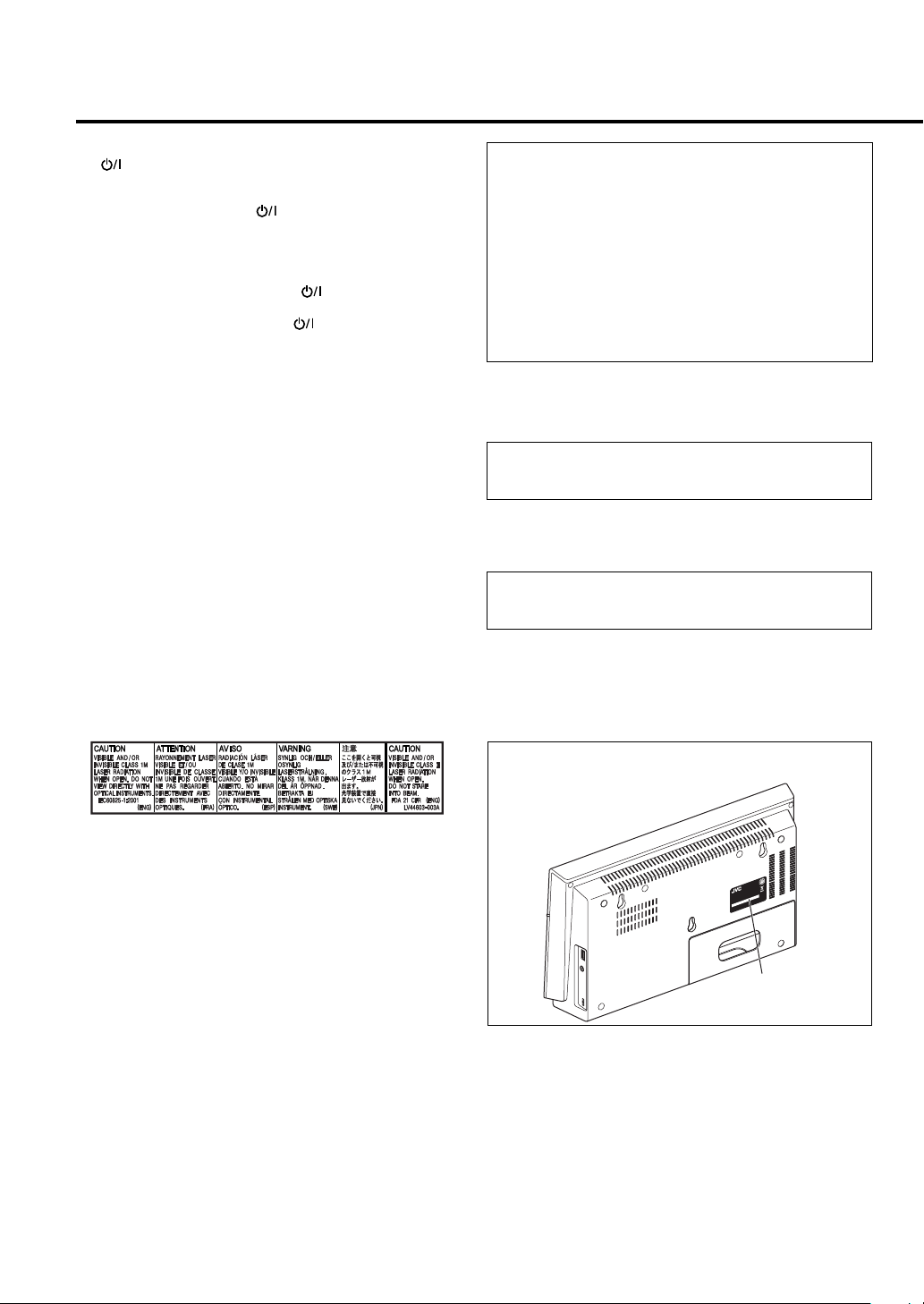
Rating label is placed on the exterior of CA-NXT10 as
illustrated below.
M
E
T
S
Y
S
NT
ONE
P
OM
C
XT10
T
N
-
C
A
CA
P
.
OM
NO
C
L
DE
O
M
ted
NA
HI
mi
C
:
N
.
I
E
n, Li
NO
D
a
L
A
A
I
M
R
E
S
of Jap
y
0
0
an
01
p
150
08
-
Com
1
1
r
1
o
7
ct
i
V
V
E
/
EN
/
E
/
B
Rating label
Page 3

Caution: Proper Ventilation
To avoid risk of electric shock and fire, and to prevent damage, locate the apparatus as follows:
1. Front: No obstructions and open spacing.
2. Sides/Top/ Back: No obstructions should be placed in the areas shown by the dimensions below.
3. Bottom: Place on the level surface. Maintain an adequate air path for ventilation by placing on a stand with a height of
10 cm or more.
Front view Side view
CA-NXT10SP-NXT10F SP-NXT10F SP-NXT10W
SP-NXT10W
[European Union only]
G-2
Page 4

Introduction
Thank you for purchasing a JVC product. Please read all instructions carefully before operation, to ensure your complete
understanding and to obtain the best possible performance from the System.
Precautions
Installation
• Install the System in a location with adequate ventilation
to prevent internal heat build-up in the System.
DO NOT install the System in a location near
heat sources, or in a place subject to direct
sunlight, excessive dust or vibration.
• Install in a place which is level, dry and neither too hot
nor too cold—between 5°C and 35°C.
• Leave sufficient distance between the System and the TV.
• Keep the speakers away from the TV to avoid
interference with the TV.
Power sources
• When unplugging the System from the wall outlet, always
pull on the plug, not the power cord.
DO NOT handle the power cord with wet
hands.
Moisture condensation
Moisture may condense on the lens inside the System in the
following cases:
• After starting to heat the room
• In a damp room
• If the System is brought directly from a cold to a warm
place.
Should this occur, the System may malfunction. In this
case, leave the System turned on for a few hours until the
moisture evaporates, unplug the power cord, then plug it
in again.
Internal heat
• Make sure there is good ventilation around the System.
Poor ventilation could overheat and damage the System.
DO NOT block the ventilation openings or
holes. If they are blocked by a newspaper or
cloth, etc., the heat may not be able to get out.
Others
Should any metallic object or liquid fall into the System,
unplug the power cord and consult your dealer before
operating any further.
DO NOT disassemble the System since there
are no user serviceable parts inside.
How to Read This Manual
• Button and control operations are explained in the table
below.
• Some related tips and notes are explained later in
the sections “Learning More about This System”
and “Troubleshooting,” but not in the same section
explaining the operations (
content has some information).
• English indications are used for the explanation of the
on-screen indications on the TV. You can select the
indication language from the Setup menu. See page 40.
Indicates that you press the button briefly.
Indicates that you press the button briefly
and repeatedly until the option you want
is selected.
Indicates that you press one of the buttons.
2
Remote
ONLY
Main Unit
ONLY
sec.
Indicates that you press and hold the
button for a specified period.
Indicates that you turn the control in the
specified direction(s).
Indicates that this operation is only
possible using the remote control.
Indicates that this operation is only
possible using the main unit.
Supplied accessories
Check to be sure that you have all the following items.
• FM antenna (×1)
• Composite video cord (×1)
• System cable (×1)
• Remote control (×1)
• Batteries (×2)
• Stand (×1)
• Core filter (×1)
If any items are missing, consult your dealer
immediately.
INFO
indicates that the
• If you are not going to operate the System for an
extended period of time, unplug the power cord from the
wall outlet.
If anything goes wrong, unplug the power cord and consult
your dealer.
1
Page 5

Contents
Introduction ............................................................ 1
Precautions ........................................................................... 1
How to Read This Manual ................................................. 1
Playable Disc/File Types ..................................................... 3
Preparations ........................................................... 4
Placing the Main Unit Vertically or Horizontally .......... 4
Connections ......................................................................... 5
When Installing the Main Unit on a Wall ....................... 11
Preparing the Remote Control .......................................... 13
Changing the Scanning Mode ........................................... 14
Display Indicators .................................................... 16
Daily Operations—Playback .................................... 17
Listening to the FM Radio .................................................. 18
Playing Back a Disc/USB Mass Storage Class Device ..... 19
Playing Back Other Equipment ......................................... 21
Daily Operations—Sound & Other Adjustments ......... 22
Turning Off the Sound in a Moment................................ 22
Adjusting the Sound............................................................ 22
Changing the Display Brightness ...................................... 23
Changing the Display Information ................................... 23
Turning Off the Power Automatically.............................. 23
Unique Video Disc/File Operations............................. 24
Selecting the Audio Track .................................................. 24
Selecting the Subtitle Language ......................................... 25
Selecting the View Angle .................................................... 25
Special Effect Playback ........................................................ 26
Advanced Disc/File Playback Operations .................... 27
Programming the Playing Order—Program Play ........... 27
Playing at Random—Random Play .................................. 28
Playing Repeatedly .............................................................. 28
Prohibiting Disc Ejection—Child Lock ............................ 29
Recording Operations .............................................. 30
Recording from a Disc ........................................................ 31
On-Screen Operations .............................................. 32
On-Screen Bar Operations ................................................. 32
Control Screen Operations ................................................ 34
Karaoke Operations ................................................. 37
Basic Procedure for Karaoke .............................................. 37
Setup Menu Operations ............................................ 39
Setting Up Playback of Discs/USB Devices/HDMI
Devices .............................................................................. 39
Setting Up the Sound and HDMI Functions ................... 41
Additional Information ............................................ 43
Learning More about This System ................................... 43
Maintenance ......................................................................... 45
Troubleshooting .................................................................. 46
Display Messages for Recording Operations ................... 48
Specifications........................................................................ 49
Parts Index ............................................................. 52
2
Page 6

Playable Disc/File Types
COMPACT
DIGITAL VIDEO
• CD-R/-RW: Recorded in the Audio CD, Video CD,
and SVCD formats. MP3, WMA, JPEG, MPEG-1,
MPEG-2, and DivX files written in accordance with the
“ISO 9660” format can also be played.
• DVD-R/-RW: Recorded in the DVD Video format and
DVD Video Recording (VR) format.
MP3, WMA, JPEG, MPEG-1, MPEG-2, and DivX files
written in the UDF-Bridge format can also be played.
• +R/+RW: Recorded in the DVD Video format. MP3,
WMA, JPEG, MPEG-1, MPEG-2, and DivX files
written in the UDF-Bridge format can also be played.
• USB mass storage class device: MP3, WMA, JPEG,
MPEG-1, MPEG-2, and DivX* files.
In addition to the above discs/files, this System can play
back audio data recorded on CD-Extra.
• The following discs cannot be played back:
– DVD-RAM, CD-I (CD-I Ready), CD-ROM, and Photo
CD
Playing back these discs will generate noise and damage
the speakers.
– 8 cm disc
An 8 cm disc cannot be played back with this System.
• CD Text and DVD Text can be played, but Text
information will not be shown on the display.
• In this manual, “file” and “track” are used
interchangeably.
• It is possible to play back finalized +R/+RW (DVD Video
format only) discs. DVD indicator lights on the TV
screen when a +R/+RW disc is loaded.
• “DVD Logo” is a trademark of DVD Format/Logo
Licensing Corporation.
• This System can play back Everio files (see page 44)
recorded on DVD, CD*, and USB mass storage class
device*.
* Only when the maximum bit rate is less than 2 Mbps.
SUPER VIDEO
DIGITAL AUDIO
Note on Region Code
DVD players and DVDs have their own Region Code
numbers. This System can play back only DVDs with an
appropriate Region Code number.
• “WRONG REGION” appears on the TV if DVD with
another Region Code is loaded.
Examples:
Caution for DualDisc playback
The Non-DVD side of a “DualDisc” does not comply with
the “Compact Disc Digital Audio” standard. Therefore,
the use of the Non-DVD side of a DualDisc in this product
may not be recommended.
IMPORTANT: Before playing a disc/file, make sure of the
following...
• Turn on the TV and select an appropriate input mode
on the TV to view the pictures or on-screen displays.
• For disc/file playback, you can change the initial setting
to your preference. See “Setup Menu Operations” on
page 39.
If “INVALID KEY” appears on the TV screen when
you press a button, the disc/file cannot perform the
operation you have tried to do.
About color system
This System can play back discs recorded in both PAL and
NTSC video format.
3
Page 7

Preparations
Placing the Main Unit Vertically or Horizontally
You can place the main unit either vertically or horizontally. Set the DISPLAY MODE switch according to the way the
main unit is placed.
• The position of the remote sensor also changes according to the setting of the DISPLAY MODE switch (see page 14).
This manual explains operations using
the illustrations of the main unit placed
vertically as examples.
Buttons and operations when the main
unit is placed horizontally are the same
as when it is placed vertically.
When placing the main unit vertically
Set the DISPLAY MODE switch to “V” (vertical) and
attach the supplied stand to the main unit (see page 10).
• When installing the main unit on a wall (see page 11),
also set the DISPLAY MODE switch to “V.”
Buttons and display indications with the DISPLAY
MODE switch set to “V”
• When placing the main unit vertically, attach the
supplied stand firmly to the back of the main unit after
connections have been completed (see page 10).
When placing the main unit horizontally
Set the DISPLAY MODE switch to “H” (horizontal).
Buttons and display indications with the DISPLAY
MODE switch set to “H”
4
Page 8
Connections
Do not connect the power cord until all other connections have been made.
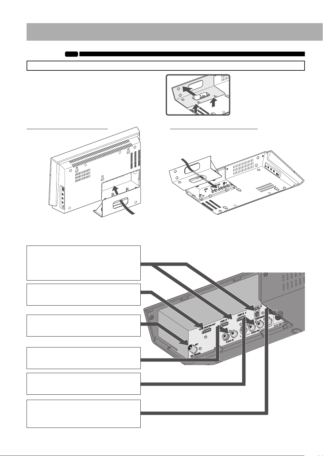
Detach the connector cover from the main unit and
connect the cords by passing them through the hole of
the connector cover.
INFO
How to detach the connector
cover
When placing the main unit vertically
Cords
• Attach the connector cover again to the main unit after connections has been completed.
When placing the main unit horizontally
Also use the same hole as illustrated below when installing
the main unit on a wall (see page 11).
Cords
Rear panel of the main unit
~ HDMI IN 1/HDMI IN 2/DIGITAL IN
(OPTICAL)
From the output of a Blu-ray device or a
Digital Set Top Box
See page 6.
Ÿ HDMI MONITOR OUT
From the input of a TV/monitor
See page 6.
! FM. ANT
From the FM antenna
See page 7.
⁄ AUDIO IN
From the output of an analog audio device
See page 7.
Ÿ VIDEO OUT
From the input of a TV/monitor
See page 6.
@ TO SP-NXT10W
From the subwoofer (with the supplied
system cable)
See page 7.
5
Page 9

~ Blu-ray device or Digital Set Top Box
HDMI cable
(not supplied)
• Connect the HDMI cable straight
not to cause damage to the
HDMI terminal.
* Connect the digital audio output to the DIGITAL IN
(OPTICAL) terminal when the device does not emit audio
signals from its HDMI output.
Optical digital cord*
(not supplied)
Protective
cap
Ÿ TV/monitor
Connect an HDMI cable, a component video cord, or a
composite video cord.
• After connecting a TV, select the appropriate video signal
output according to the TV. See pages 14 and 15.
• To select progressive scanning mode (see page 14), use
the HDMI MONITOR OUT terminal or COMPONENT
jacks.
When connecting your TV
Connect your TV directly to the System. Connecting the
System to a TV via other device, such as a VCR or an
HDD/DVD recorder, may interfere with your viewing.
Connecting an integrated TV/VCR system to the System
may also interfere with your viewing.
HDMI cable (not supplied)
Use an HDMI cable of less than
2 m.
• Connect the HDMI cable
straight not to cause damage
to the HDMI terminal.
When connecting a Blu-ray device or a Digital Set Top Box
• When connecting with an HDMI cable, use the HDMI
cable of less than 2 m.
• Scanning mode setting of the System (see page 14) does
not affect the video signals of the HDMI MONITOR
OUT terminal coming from the HDMI IN 1 and 2
terminals.
• When connecting the digital audio output of the device
to the DIGITAL IN (OPTICAL) terminal, make sure of
the following:
– Set the digital audio output setting of the device
properly. For details, refer to the manual of the device.
Following signals can be reproduced on the System:
Dolby Digital, DTS Digital Surround, Linear PCM
• For the audio signals coming from the HDMI IN 1 and 2
terminals, you can choose whether to emit the signals to
the TV through the HDMI MONITOR OUT terminal or
reproduce the sound on the System. For details, see page
41.
Component video cord
(not supplied)
Blue
Red
Green
Composite video cord
(supplied)
• When you use an HDMI cable, make appropriate settings
in the Setup menu (see pages 39 – 42).
• This System is compatible with some basic functions of
HDMI CEC. For details, see page 42.
• Playback sound may be interrupted when operating the
TV connected with the HDMI cable.
6
Page 10
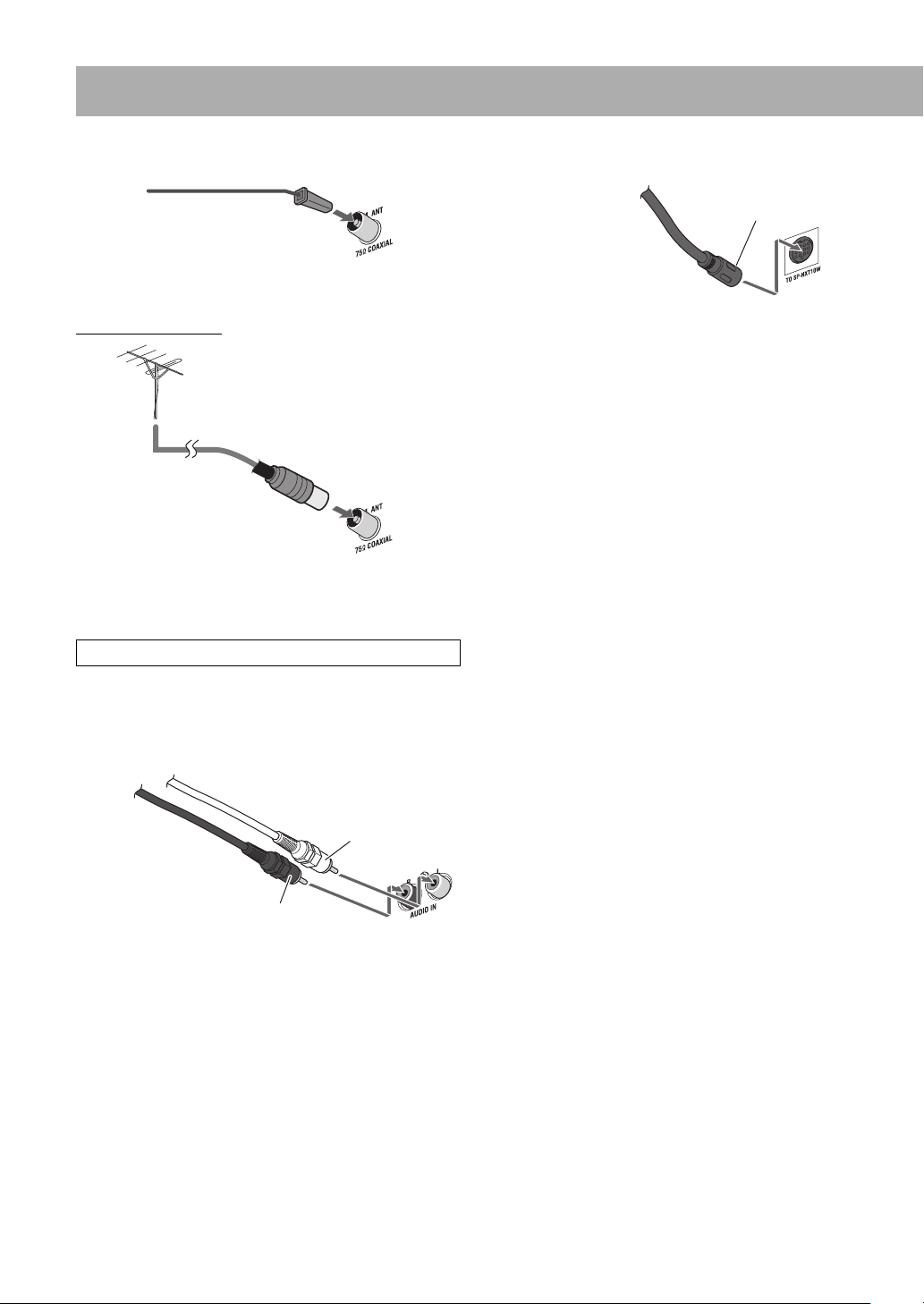
! FM antenna
FM antenna (supplied)
@ System cable
From the subwoofer
Arrow
Extend it so that you can obtain the best reception.
For better FM reception
FM outdoor antenna
(not supplied)
Disconnect the supplied FM antenna, and connect to an
outdoor FM antenna using a 75 Ω wire with coaxial type
connector.
This System cannot receive the AM band.
⁄ Analog audio device
Audio cord (not supplied)
System cable (supplied)
Connect the system cable with the arrow side facing up.
After connections on the rear of the main unit have been
completed, connect speakers and the system cable to the
subwoofer. See pages 8 and 9.
White
Red
7
Page 11
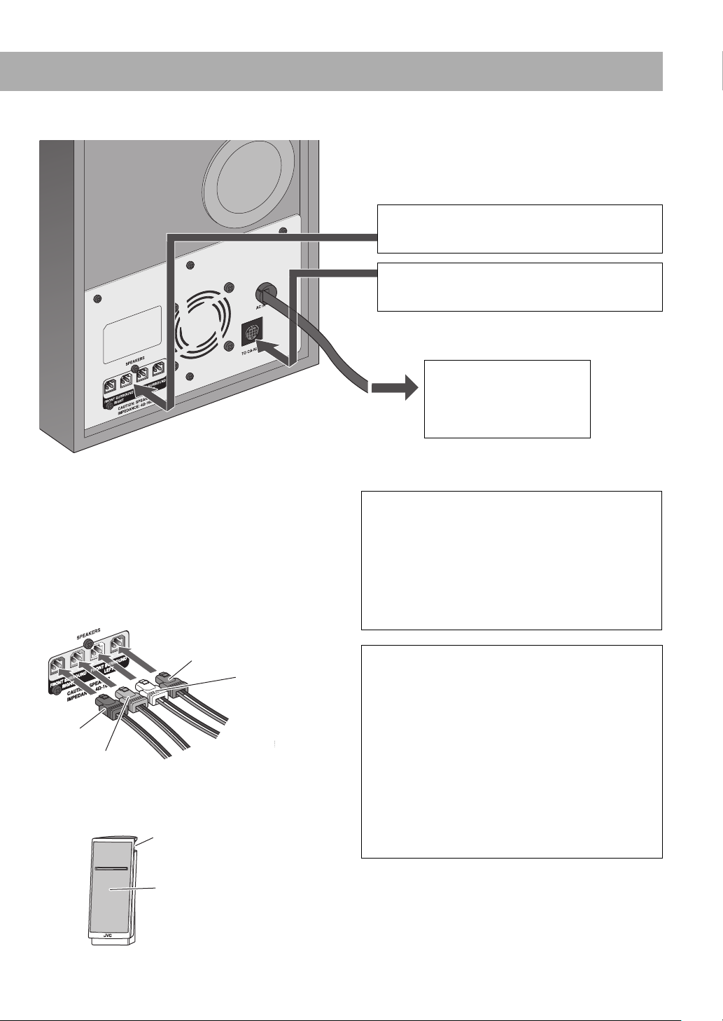
Rear panel of the subwoofer
¤ SPEAKERS
From the speakers
See below.
# TO CA-NXT10
From the main unit
See page 9.
‹ To a wall outlet
Plug in the power cord
only after all connections
have been completed.
See page 9.
¤ Speakers
Connect the speakers to the subwoofer by connecting the
colored connectors to the same color terminals on the rear
of the subwoofer.
Blue
White
Red
Gray
From the right
speaker
Speaker unit for the surround channel
(on the top)
Speaker unit for the front channel (on
the front)
From the left
speaker
CAUTION:
• The supplied speakers are manufactured exclusively
for use with the NX-T10 System. Do not connect
the supplied speakers to any devices other than the
subwoofer of the System (SP-NXT10W). Doing so may
damage the speakers.
• Do not connect external speakers together with the
supplied speakers. The change in impedance may
damage the System.
IMPORTANT
• Improper speaker cable connection reduces the stereo
effect and sound quality.
• The supplied left/right speakers are magnetically
shielded, but color irregularity may occur on the TV.
To prevent color irregularity, set up the speakers
following the instructions below. (The subwoofer is not
magnetically shielded.)
1 Turn off the main power of the TV before setting up
the speakers.
2 Place the speakers enough distance from the TV so
that they do not cause color irregularity on the TV.
3 Wait for approximately 30 minutes before turning on
the main power of the TV again.
Continued on the next page
8
Page 12
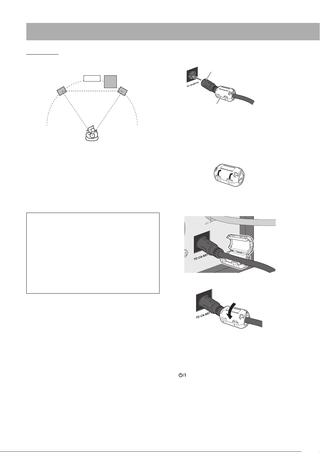
Speaker layout
# System cable
Main unit
Subwoofer
Right speakerLeft speaker
This System is designed to provide virtual surround sound
by positioning the 3 speakers in front.
Omni-Directional Speakers provides a wide sound field
and realistic acoustic ambience.
• When it is difficult to place the speakers as illustrated
above, you can adjust the output level of the speakers to
have a better sound effect. See page 42.
CAUTION:
When installing the left and right speakers on a wall:
• When installing the speakers on a wall, be sure to have
the speakers installed by qualified personnel.
• DO NOT install the speakers on the wall by yourself
to avoid unexpected damage from them falling off the
wall due to incorrect installation or weakness in wall
structure.
• Care must be taken in selecting a location for speaker
installation on a wall. Injury to personnel or damage
to devices may result if the installed speakers interfere
with daily activities.
Arrow
System cable (supplied)
Core filter (supplied)
Connect the system cable with the arrow side facing up.
From the main unit
How to attach the core filter
Attach the provided core filter to the system cable, then the
core filter reduces interference.
1 Release the stopper of the core filter.
2 Run the system cable through the core filter, and place
the core filter at the root of the connector connected
to the subwoofer.
3 Close the core filter until it clicks shut.
‹ Power cord
Connect the power cord of the subwoofer after other
connections have been completed.
lamp on the main unit and the POWER ON/
The
STANDBY lamp on the subwoofer light red.
9
Page 13
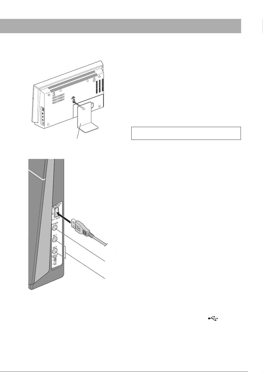
To attach the supplied stand to the main unit
When placing the main unit vertically, make sure to attach the supplied stand to the main unit. Attach the supplied stand
firmly to the back of the main unit after connections have been completed.
CAUTION:
Stand (supplied)
Detach the stand before carrying the main unit.
Side panel of the main unit
From a USB mass storage class device
See page 18.
See page 37.
When connecting a USB mass storage class device
• When connecting with a USB cable, use the USB 2.0 cable whose length is less than 1 m.
• You can connect a USB mass storage class device such as a USB flash memory device, hard disk drive, multimedia card
reader, etc. to this System.
• You cannot connect a computer or JVC Everio camcorder to the USB MEMORY REC/PLAY terminal (
System.
• Electrostatic shock at connecting a USB device may cause abnormal playback of the device. In this case, disconnect the
USB device then reset this System and the USB device.
) of the
10
Page 14
When Installing the Main Unit on a Wall
You can install the main unit on a wall.
CAUTION:
• Be sure to have the main unit installed by qualified
personnel.
• DO NOT install the main unit on the wall by yourself
to avoid unexpected damage from them falling off the
wall due to incorrect installation or weakness in wall
structure.
• Care must be taken in selecting a location for
installation on a wall. Injury to personnel or damage to
devices may result if the main unit installed on a wall
interfere with daily activities.
• The main unit weighs approximately 2.3 kg. Sufficient
care must be required when installing the main unit
on a wall to prevent any accidents caused by the main
unit’s falling off.
• Before installing the main unit on a wall, check the wall
(or other related aspects) to install, and verify whether
the strength of the wall will be sufficient to support the
weight of the main unit.
• Do not install the main unit to a plywood or
plasterboard wall. The main unit will fall and sustain
damage as a result.
• The screws needed for attachment are not supplied.
Use screws which are compatible with the strength and
material of the pillar or wall.
• When installing the main unit, the screws must
be secured tightly in all three locations. Failure in
installing the main unit to the wall using all three holes
on the back of the main unit makes for an unstable
installation and it constitutes a safety hazard as the
main unit may fall down.
Example of attachment
The procedure below is an example of how to attach the
main unit to a wall.
It does not make any guarantee for safety while using the
main unit on the wall. Take into account such factors as the
material, strength, and the status of the wall as well as the
reinforcing material, and the possible changes that will take
place over time.
• You need to connect the cords to the main unit before
attaching it to the wall.
• DO NOT plug the power cord into an AC outlet before
installing the main unit on the wall.
1 Select the place (wooden wall) where the main unit is
to be attached.
Avoid a plywood or plasterboard wall.
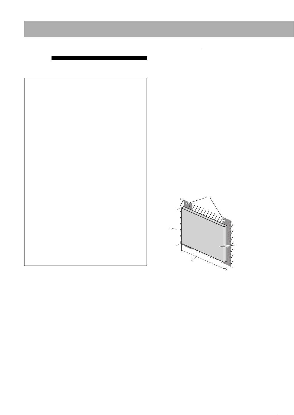
2 For reinforcement purposes, prepare the wooden
board which will be used to install the main unit on
the wall.
Before proceeding, check the position of the supports
inside the wall.
Use a sturdy board sized as below:
Supports inside the wall
A
Board
B
11
C
A (Height): Higher than the main unit
B (Width): Wider than the distance between the two
supports inside the wall
C (Thickness): 9 mm to 15 mm
Page 15
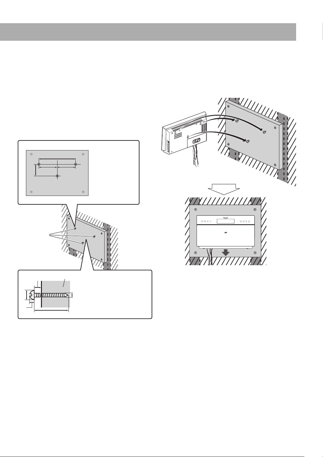
3 Attach the board to the wall.
Anchor the board securely in at least four places to the
supports inside the wall.
The diameter of the screws must be more than 4 mm
and their length must be 3 times the thickness of the
board mounted on the wall (also take the thickness of
the wall into account).
4 Mount three screws (not supplied) to the board which
has been attached on the wall.
Attach the screws to the board as illustrated below.
D
D: 240 mm
E
FF
E: 78 mm
F: 120 mm
5 Hook the main unit onto the mounted screws and
slide the main unit down.
Make sure that the main unit is installed securely.
• Adjust the screws if the main unit is not installed
securely.
Screws (not
supplied)
G
H
I
Slide down.
Board
J
G: Keep the space of 6 to 7 mm.
H: 10.5 to 12 mm
I: Within 3.5 mm
K
J: 12 to 19 mm (According to
the thickness of the board)
K: 5 mm
Continued on the next page
12
Page 16

• Do not place anything on top of the main unit. Doing so
may cause the main unit to fall down, and cause injury to
the persons around.
• Do not climb onto the main unit or hang from it. Doing
so may damage the main unit and/or cause injury to the
person.
Take care specially when there are small children at the
home.
• Avoid sandwiching the cords between the main unit and
wall. This may upset the balance of the main unit and
cause the main unit to fall down.
• Make sure that the connected cords will not interfere
with daily activities and that the users will not be caught
in the cords.
• Do not pull the connected cords with excessive force.
• Check regularly that none of the screws are loose.
• In the event that the main unit has fallen, turn off the
power, disconnect the power cord from the AC outlet.
Then, contact your dealer for an inspection and repairs.
Using the main unit in this state may cause a fire or
electrical shock.
• Do not place valuables (breakables) underneath the
location where the main unit is installed. They will be
damaged if the main unit should fall.
• JVC bears no responsibility for any accidents or damage
resulting from inadequate assembly or mounting,
insufficient strength of attachment, misuse or abuse, or
natural disasters.
Preparing the Remote Control
Insert the battery into the remote control by matching the
polarity (+ and –) correctly.
R03/LR03/AAA
• If the range or effectiveness of the remote control
decreases, replace both batteries.
13
Page 17

When using the remote control
Point the top of the remote control towards the remote
sensor as directly as possible. If you operate it from a
diagonal position, the operating range (approx. 5 m) may
be shorter.
When placing the main unit vertically (with the DISPLAY MODE
switch set to “V”)
Remote sensor
When placing the main unit horizontally (with the DISPLAY
MODE switch set to “H”)
Remote sensor
Changing the Scanning Mode
Select the video signal output according to
the type of your TV after connecting the main
unit to the TV.
• Turn on the System before setting the scanning mode.
See page 17.
• There is no need to make this setting when you connect
the TV with a composite video cord.
INFO
Remote
ONLY
1 Select DVD/CD as the source.
2 Enter the scanning mode setting.
Ex.: When the TV is connected to the HDMI
MONITOR OUT terminal
• Finish the following process while the setting item is
flashing.
Continued on the next page
14
Page 18

3 Select the scanning mode.
When connecting the TV to the HDMI MONITOR OUT
terminal
For NTSC video
format
AUTO AUTO
NT 480P
NT 720P
NT1080I
NT1080P
AUTO
NT 480P/PAL 576P
NT 720P/PAL720P
NT1080I/PAL1080I
NT1080P/PAL1080I
When connecting the TV to the COMPONENT jacks or VIDEO
jack
Normally select this.
Select a scanning mode when
it is needed.
• Available settings vary
according to the available
resolutions of the
connected TV.
For NTSC video
format
N 480P
For PAL video
format
PAL 576P
PAL 720P
PAL1080I
PAL1080P
For PAL video
format
P 576P
• This setting works only for the video signals played with
the built-in disc player on the main unit. Signals coming
through the HDMI IN 1/2 terminal are not affected.
• “480,”“576,” “720,” and “1080” refer to the number of
the scanning lines. Generally, the larger the number, the
better picture can be obtained.
• “I” refers to the interlaced scanning. “P” refers to the
progressive scanning. A better picture can be obtained in
the progressive scanning than in the interlaced scanning.
• When an HDMI video signal is output through the
HDMI MONITOR OUT terminal, the HDMI indicator
lights on the display.
• When an HD (High Definition) video signal is output
through the HDMI MONITOR OUT terminal, the HD
indicator lights on the display.
• When “480P,” “576P,” “720P,” or “1080P” is selected, the
PROGRESSIVE indicator lights on the display.
• The scanning mode setting is stored if the main unit is
turned off (standby).
N 480P/P 576P
N 480I/P 576I
4 Store the setting.
15
N 480I
Select this when connecting the TV
compatible with the progressive
scanning to the COMPONENT
jacks.
Progressive scanning delivers a high
quality picture.
Select this in the following cases:
• When connecting the TV with the
composite video cord.
• When connecting the TV that
does not support the progressive
scanning.
P 576I
Page 19

Display Indicators
The indications on the display tell you a lot of things while you are operating the System.
Before operating the System, be familiar with when and how the indicators light on the display.
1 FM reception indicators
• ST (stereo): lights while an FM stereo station with
sufficient signal strength is tuned in.
• MONO (monaural): lights while receiving an FM
station in monaural.
2 Digital audio signal format indicators
3 HDMI indicator
• Lights when an HDMI video signal is output.
4 FM indicator
• Lights when FM is selected as the source.
5 CHAP. (chapter) indicator
• Lights to indicate the chapter number.
6 TRK (track) indicator
• Lights to indicate the track number.
7 PG (program) indicator
• Lights when an Original Program on DVD-VR is
played.
8 PL (Play List) indicator
• Lights when a Play List on DVD-VR is played.
9 Playback mode indicators
• PRG: lights when Program Play is activated.
• RND: lights when Random Play is activated.
• Repeat Mode indicators:
–
–
–
–
: lights when One Track/File/Chapter Repeat is
activated.
: lights when One Group/Title/Original
Program/Play List Repeat is activated.
: lights when All Track/File/Title/Original
Program Repeat is activated.
: lights when A-B Repeat is activated.
p Microphone indicator
• Lights when “DVD/CD,” “HDMI 1,” “HDMI 2,”
“USB,” or “DGTL (DIGITAL) IN” is selected as the
source and (a) microphone(s) is/are connected.
q REC (recording) indicator
• Flashes when recording starts and remains lit while
recording.
w USB indicator
• Lights in the following cases:
– When “USB” is selected as the source and a USB
mass storage class device is connected.
– When recording to a USB mass storage class device.
e PROGRESSIVE (progressive) indicator
• Lights when the progressive scanning mode is
selected.
r HD (High Definition) indicator
• Lights when a High Definition (720p/1080i/1080p)
video signal is emitted from the HDMI MONITOR
OUT terminal.
t Main display
• While listening to FM: band (or preset number) and
station frequency appear.
• While “HDMI 1,” “HDMI 2,” “DGTL (DIGITAL) IN,”
or “AUDIO IN” is selected as the source: the current
source name appears.
• While playing a disc or file: current status appears.
16
Page 20

Daily Operations—Playback
Remote control
Number
buttons
Main unit
In this manual, operations using the remote control
are mainly explained; however, you can use the buttons
and controls on the main unit if they have the same (or
similar) name and marks.
1 Turn on the power.
The lamp on the main unit lights blue.
• The POWER ON/STANDBY lamp on the
subwoofer also lights blue.
• Instead of pressing
pressing one of the following buttons:
– DVD/CD, HDMI 1/2, INPUT, FM, SOURCE, 3,
0
, the System is turned on by
2 Select the source.
From the Remote control
• For disc: Press DVD/CD. See page 19.
• For FM: Press FM. See page 18.
• For HDMI 1/2: Press HDMI 1/2 repeatedly to select
“HDMI 1” or “HDMI 2.” See page 21.
• For USB/DIGITAL IN/AUDIO IN:
Press INPUT repeatedly to select “USB,” “DGTL
IN,” or “AUDIO IN.” See pages 19 and 21.
On the Main unit
Pressing SOURCE repeatedly changes the source as
follows:
17
• You can change the display information by pressing
DISPLAY. For details, see page 23.
3 Adjust the volume.
You can adjust the volume level from “VOL MIN”
(level 0) to “VOL MAX” (level 60).
To turn off (standby) the System
The lamp on the main unit lights red.
• The POWER ON/STANDBY lamp on
the subwoofer also lights red.
• A small amount of power is always
or
or
consumed even while on standby.
DO NOT turn off (standby) the System
with the volume set at an extremely high
level; otherwise, the sudden blast of sound
may damage your hearing, speakers and/or
headphones when you turn on the System or
start playback.
Page 21

For private listening
Connect a pair of headphones to the PHONES jack
on the main unit (see page 10). The sound will no
longer come out of the speakers. Be sure to turn down
the volume before connecting or putting on the
headphones.
• Disconnecting the headphones will activate the
speakers again.
• The surround effect is automatically deactivated while
connecting a pair of headphones.
How to select a number
Press the number buttons to enter the number, then
press ENTER.
Some items are automatically selected without pressing
ENTER.
Examples:
To select number 7, press 7, then ENTER.
To select number 14, press 1, 4, then ENTER.
To select number 78, press 7, 8, then ENTER.
To select number 104, press 1, 0, 4, then ENTER.
Remote
ONLY
INFO
Listening to the FM Radio
• This System cannot receive the AM band.
To tune in to a station
While FM is selected...
Remote
If the FM reception is poor
The MONO (monaural) indicator lights on the display.
Reception will improve though stereo effect is lost—
Monaural reception.
To restore the stereo effect, press the button again. The ST
(stereo) indicator lights on the display when an FM stereo
broadcast with sufficient signal strength is received.
To preset the stations
You can preset 30 FM stations.
ONLY
Remote
ONLY
1 Tune in to a station you want to preset.
2 Activate the preset number entry mode.
• Finish the following process while the preset number
is flashing.
3 Select a preset number for the station you store.
or
• To select a number with the number buttons, see
“How to select a number” on the left column.
4 Store the station.
Frequency starts changing on the display.
When a station (frequency) with sufficient signal strength
is tuned in, the frequency stops changing.
• When you repeatedly press the button, the frequency
changes step by step.
To manually stop the search, press either button.
Remote
To tune in to a preset station
While FM is selected...
Select the preset number for the station you stored.
or
• To select a number with the number buttons, see
“How to select a number” on the left column.
ONLY
18
Page 22

Playing Back a Disc/USB Mass Storage Class Device
To insert a disc
The disc player panel is automatically closed and the
System starts reading the disc.
To close the disc player panel manually, press 0.
• For some discs, playback automatically starts after the
To connect a USB mass storage class device
• For connecting a USB mass storage class device, see page
• Always set the volume level to the minimum when
• To disconnect a USB mass storage class device safely,
While DVD/CD or USB is selected...
To start:
To pause: To stop:
INFO
Label side
System finishes reading the disc.
10.
connecting or disconnecting a USB mass storage class
device.
turn off the System before disconnecting the device.
To play back a disc/USB mass storage class device
If different types of playable files (audio/still
Remote
ONLY
picture/moving picture) are recorded
Select a file type on the control screen (on the TV).
• For still/moving picture files, it appears while playback is
stopped. For details, see page 35.
1
Control screen appears on the TV.
1 Audio
2 Still picture
3 Moving picture
123
Current file type to play
2 Select a file type.
When the sound of DVD Video or DVD-VR is not loud enough
DVD sound is sometimes recorded at a lower level than
other discs and sources. You can set the increase level for
the currently loaded DVD (without changing the volume
level). To set the increase level, see page 41.
Resume play
The System can store the stop point of playback. When you
start playback again by pressing 3, playback starts from the
position where you have stopped.
To stop completely, press 7 twice.
• The following operations also erase the memory of the
stop point:
– Pressing 0 to open the disc player panel
– Pressing
turned off (standby).
to turn on the System when the System is
To release, press 3.
19
Page 23

Remote
To select a folder/group
ONLY
You can select a folder/group by using the control screen.
For details, see page 35.
Remote
To select a chapter/track/file
ONLY
• For VCD/SVCD, cancel PBC (see page 21).
While playing...
• When you press 4 for the
first time, you will go back to the
beginning of the current chapter/
track/file.
• You can also select the position to play by using the onscreen bar. For details, see page 33.
Remote
To locate a particular portion
ONLY
• This does not function for JPEG files.
While playing...
Remote
To locate an item directly
ONLY
You can select a title/chapter/track/file directly and start
playback.
• For DVD Video, you can select a title before starting
playback, while you can select a chapter after starting
playback.
• To select a number, see
“How to select a number” on
page 18.
• You can also select the position to play by using the onscreen bar. For details, see page 33.
Remote
To play back using the disc menu
ONLY
For DVD Video
1 Show the disc menu.
2 Select an item on the disc menu.
Returns to
normal playback
Returns to
normal playback
• For MP3/WMA/MPEG-1/MPEG-2/DivX files, the search
speed and indications on the TV are different from those
above.
• No sound comes out if searching is carried out while
showing the moving picture.
To return to normal playback, press 3.
• You can also select the position to play by using the onscreen bar. For details, see page 33.
• For some discs, you can also select items by entering
the number using the number buttons.
Continued on the next page
20
Page 24

For SVCD/VCD with PBC
When a disc menu appears on the TV, select an item on the
menu. Playback of the selected item starts.
• While playing a disc with PBC, “PBC” appears on the onscreen bar (see page 32).
• To select a number, see “How
to select a number” on page 18.
Playing Back Other Equipment
You can listen to other equipment connected to the System.
• Make sure to turn down the volume on the System to
minimum level before starting playback.
• For connecting other equipment, see pages 5 – 7.
From the Remote control
For a device connected to HDMI IN 1/HDMI IN 2
To move to the next or previous page of the current
menu:
Moves to the next page.
Moves to the previous page.
To show the menu during playback:
To cancel PBC, select a track to play by using the on-screen
bar. For details about the on-screen bar operation, see page
33.
To activate PBC again, press MENU to show the menu.
To rotate a JPEG file
To rotate the file by 90 degree:
For a device connected to AUDIO IN/DIGITAL IN
On the Main unit
• With the HDMI CEC function, you can operate other
devices through the HDMI connection. For details about
the HDMI CEC function, see page 42.
To reflect the file
vertically:
21
To reflect the file
horizontally:
Page 25

Remote control
Daily Operations—Sound & Other Adjustments
For other audio signals than 5.1 channels
NATURAL
PL MOVIE
PL MUSIC
Turning Off the Sound in a Moment
To restore the volume, press again, or
adjust the volume level.
Adjusting the Sound
INFO
Remote
ONLY
Remote
ONLY
To activate the surround mode
SURR OFF
For FM/AUDIO IN
NATURAL
For Disc/USB/HDMI 1/HDMI 2/DGTL IN
The System reproduces the sound as follows:
• Left channel sound: From the speaker
• Right channel sound: From the speaker
Dolby Pro Logic II is deactivated when this
mode is selected.
Dolby Pro Logic II Movie (PL MOVIE) or
Dolby Pro Logic II Music (PL MUSIC) is
activated.
• When “PL MOVIE” or “PL MUSIC” is
Stereo sound is reproduced from the speaker
units on the front of the speakers.
The System reproduces the sound as follows:
• Left channel sound: From the speaker
For a 5.1 channel digital audio signal (Dolby Digital or DTS
Digital Surround)
The surround mode appropriate for the audio signal is
automatically activated.
or indicator lights on the display.
When the System reproduces a 5.1 channel digital audio
signal, each channel is reproduced as follows:
• Front channels: Reproduced from the speaker units on
the front of the speakers.
• Center channel: Reproduced from the speaker units
on the front of the speakers, half from the left speaker
and half from the right speaker.
• Surround channels: Reproduced from the speaker
units on the top of the speakers.
SURR OFF
Subwoofer is always activated to reproduce the bass sound.
• Right channel sound: From the speaker
Dolby Pro Logic II is deactivated when this
mode is selected.
Stereo sound is reproduced from the speaker
units on the front of the speakers.
units on the top and front of the left
speaker
units on the top and front of the right
speaker
selected,
display.
units on the top and front of the left
speaker
units on the top and front of the right
speaker
indicator lights on the
If you press SURROUND to set the surround mode to
“SURR OFF,” the audio signal is down-mixed into 2
channels and reproduced only from the speaker units on
the front of the speakers.
22
Page 26

To adjust the tone
You can adjust the bass and treble level from –10 to +10 (by
2 step).
To adjust the bass
Changing the Display Information
You can change the display information of Disc/File
playback.
Remote
ONLY
Elapsed playing time*1*2
Source
Disc/file type
To adjust the treble
*1 Current picture (file) number for JPEG files
2
*
Each time you press and hold DISPLAY for more than 3
seconds, you can change the time indication on the display
and on-screen bar. For details, see page 32.
3
For CD/SVCD/VCD: Track number
*
For MP3/WMA/JPEG/MPEG-1/MPEG-2/DivX files:
Changing the Display Brightness
You can dim the display.
Remote
ONLY
Group and file number
For DVD Video/DVD-VR: Title and chapter number
Turning Off the Power
While the System is turned on...
(Canceled)
DIMMER 1
DIMMER 2
DIMM OFF
The display and illumination dim.
The display and illumination are dimmer
than “DIMMER 1.”
• When playing a DVD Video/DVD-VR, all
illuminations except the display and
lamp are turned off.
Cancels the dimmer function.
Automatically
Sleep Timer
You can set the shut-off time so that you can go to bed
without turning off the System yourself.
1 Specify the time (in minutes).
Title and chapter
number*
(Canceled)
3
Remote
ONLY
23
2 Wait until the set time disappears.
To check the time remaining until the shut-off time,
press SLEEP once.
• If you press the button repeatedly, you can change the
shut-off time.
Auto Standby
While DVD/CD or USB is selected...
The System turns off (standby) automatically if no
operation is done for about 30 minutes after playback is
stopped.
Page 27

Remote control
123
Unique Video Disc/File Operations
Selecting the Audio Track
For DVD Video: While playing back a chapter/file
containing several audio languages, you can select the
language to listen to.
For DVD-VR/SVCD/VCD: While playing back a track,
you can select the audio channel to listen to.
While playing a DVD Video...
Ex.:
:
1 Language
2 Audio format
3 Channel
[ 1 ENGLISH ] D 5.1CH
INFO
Remote
ONLY
[ [ [
[
1 ENGLISH
: :
D 5.1CH
]
[
2 FRENCH] D 5.1CH
3 JAPANESE
[
3 JAPANESE] D 5.1CH
:
While playing a DVD-VR or SVCD/VCD...
:[1]:[
CHANNEL
CHANNEL
CHANNEL
CHANNEL
STEREO
To listen to normal stereo
(2-channel) playback.
MONO L
MONO R
MIX MONO
To listen to the left audio channel.
To listen to the right audio channel.
To listen to monaural sound the left
and right sounds are mixed.
• SVCD can have 4 audio channels. SVCD usually uses
these 4 channels to record two 2-channel recordings
(STEREO).
]:[
2
:[MONO L
:[MONO R
]
]
:[MIX MONO
:[STEREO
]
]
3
]
24
Page 28

Remote
Selecting the Subtitle Language
ONLY
For DVD Video: While playing back a chapter/file
containing subtitles in different languages, you can select
the subtitle language to display on the TV.
For DVD-VR: While playing, you can turn the subtitles on
or off.
For SVCD: While playing, you can select the subtitles even
if no subtitles are recorded on the disc.
While playing a DVD Video...
Remote
Selecting the View Angle
ONLY
For DVD Video only: While playing back a chapter
containing multi-view angles, you can view the same scene
from different angles.
While playing a DVD Video...
[
] [
1/3
2/3
]
[
3/3
]
Ex.:
[
[ 1 ENGLISH
:
]
]
While playing a DVD-VR...
While playing an SVCD...
:
[
]
OFF
[ 1/3 ]:
[
:
[ 2 FRENCH
]
[ 3 JAPANESE ]
]
:
[ 3 JAPANESE
]
[ 2/3 ]:
[ 3/3 ]:
25
:
:
:
:
[
]
1
[
]
2
[
]
3
[
]
4
Page 29

Special Effect Playback
INFO
Still picture playback
To display the still picture:
While playing...
To resume normal playback, press 3.
Remote
Slow-motion playback
• This function is used only while playing DVD Video/
DVD-VR/SVCD/VCD.
While pausing....
ONLY
To replay the previous scenes
Remote
ONLY
(One-Touch Replay)
• This function is only used while playing DVD Video/
DVD-VR.
While playing....
The playback position moves back about
10 seconds before the current position
(only within the same title for DVD
Video).
Reverse slow
motion
*
starts.
SB 1/2
SB 1/3
SB 1/4
SB 1/5
SB 1/6
SB 1/7
SB 1/8
Returns to
normal playback
* Only available for DVD Video.
To resume normal playback, press 3.
Forward
slow motion
starts.
SF 1/2
SF 1/3
SF 1/4
SF 1/5
SF 1/6
SF 1/7
Returns to
normal playback
26
Page 30

Advanced Disc/File Playback Operations
Remote control
Number
buttons
Main unit
Programming the Playing Order— Program Play
INFO
Remote
ONLY
You can arrange the playing order of the chapters/tracks/
files (up to 32) before you start playback.
• Program Play cannot be used for DVD-VR and JPEG/
MPEG-1/MPEG-2/DivX files.
1 Before starting playback, activate Program Play.
RANDOM:[ON]
RANDOM:[OFF]
(Canceled)
TC
TC
TC
1
9
2
10
3
11
4
12
5
13
6
14
7
15
8
16
PROGRAM PLAY CLEAR
On the TV (Ex. DVD)
• To exit from the program menu screen and quit
Program Play, press 7.
TC
17
25
18
26
19
27
20
28
21
29
22
30
23
31
24
32
2 Select chapters/tracks/files you want for Program
Play.
27
Select a chapter or track/file number.
• To select a number, input a number directly with the
number buttons (see page 18).
• To erase the entire program, select “CLEAR” on the
program menu screen, then press ENTER.
3 Repeat step 2 until you complete your program.
4 Start playback.
Playback starts in the order you have
programmed.
• You can also start playback by
selecting “PLAY” on the program
menu screen and then pressing
ENTER.
To skip: To pause: To stop:
To release, press
3.
Pressing 7
deactivates
Program Play.
Page 31

Playing at Random— Random Play
You can play all chapters or tracks at random.
• Random Play cannot be used for DVD-VR and JPEG/
MPEG-1/MPEG-2/DivX files.
Remote
ONLY
1 Before starting playback, activate Random Play.
RANDOM:[ON]
Playing Repeatedly
For DVD Video
While playing...
(Canceled)
INFO
Remote
ONLY
RANDOM:[OFF]
(Canceled)
2 Start playback.
Playback starts in random order.
• For some discs/files, playback automatically starts
without pressing 3.
To skip a chapter/
track:
To exit Random Play
Before or after playback...
To pause: To stop:
To release, press
3.
For CD/SVCD/VCD
While playing (without PBC for SVCD/VCD)...
(Canceled)
For DVD-VR
While playing an Original Program...
(Canceled)
While playing a Play List...
(Canceled)
For MP3/WMA/JPEG/MPEG-1/MPEG-2/DivX files
While playing...
(Canceled)
RANDOM:[ON]
RANDOM:[OFF]
(Canceled)
• Pressing TIME SEARCH also cancels Random Play.
CHAPTER
TITLE
REP 1
REP GROUP
REP PG
REP PL
REP ALL
• Repeat Play will be canceled when you stop playback.
Repeats the current chapter.
Repeats the current title.
Repeats the current track/file.
Repeats the current folder/group.
Repeats the current Original Program.
Repeats the current Play List.
Repeats all the contents or programmed
tracks/files.
28
Page 32

Remote
A-B Repeat
You can repeat playback of a desired portion by specifying
the beginning (point A) and the ending (point B).
• A-B Repeat cannot be used for JPEG files and some
DVDs.
ONLY
1 While playing, select the start point (A).
2 Select the end point (B).
Press REPEAT A-B again.
• You can search for the end point using the ¡
button.
Prohibiting Disc Ejection—
Main Unit
ONLY
Child Lock
You can lock the disc ejection so that no one can eject the
loaded disc.
While the System is turned on and the disc player panel
is closed...
To cancel A-B Repeat, press REPEAT A-B again.
• A-B Repeat will also be canceled when you stop playback
or skip the chapter or track.
To cancel the prohibition, repeat the same procedure.
“UNLOCKED” appears on the display.
29
Page 33

Remote control
Recording Operations
Before You Start Recording
• It may be unlawful to record or play back copyrighted
material without the consent of the copyright owner.
• The recording level is not affected by the volume.
• Surround mode effect, tone adjustment, and the speaker
level settings (see pages 22, 23, and 42) do not affect
recordings.
• Random Play and Repeat Mode are canceled during
recording mode.
• You can record up to 99 tracks per group to the USB
device.
• Tracks which are recorded to the USB device will be
converted into MP3 format.
• You cannot start recording into a USB device while
“READING” is shown on the display.
• You cannot record tracks in the root group as much as
into other groups. This is not a malfunction. It depends
on the USB device used.
• Do not disconnect a USB device while playing/recording.
It may cause malfunction.
About SCMS (Serial Copy Management System)
The System uses the Serial Copy Management System
which allows only first-generation digital copies to be made
of premastered software such as regular CDs.
If you try to record from a duplicated CD-R or CD-RW
into the USB device, “SCMS VLT (violation)” appears on
the display.
INFO
1st generation
2nd generation
30
Page 34

Remote
Recording from a Disc
You can record tracks in digital recording from a CD onto
the USB device.
• Do not vibrate the System while recording tracks. It may
damage the recorded tracks.
Before recording....
• Connect a recordable USB device to the USB MEMORY
REC/PLAY (
• Turn on the TV and change the input of the TV to the
one the System is connected.
) terminal. (See also page 10.)
ONLY
1 Select DVD/CD as the source.
2 Start recording.
• The System will automatically create the new group as
“JVC_A01.” If “JVC_A01” already exists or the number
of tracks recorded for one group is more than 99 tracks,
“JVC_A02,” “JVC_A03,” and so on will be created.
• You cannot change the source while recording.
• The tracks are recorded in the normal order even if
Program Play is activated.
• Some messages may appear on the display when
recording. For details about the messages on the display
for recording operations, see page 48.
• Playback sound may be interrupted when operating the
TV connected with the HDMI cable. However, recording
is not affected by the interruption.
To stop recording
manually:
To record the playing
track (1 track):
During play or pause...
31
Page 35

Remote control
On-Screen Operations
To change the indication of the on-screen bar
Each time you press and hold DISPLAY for more than 3
seconds, the on-screen bar changes as follows:
Ex.: For DVD Video
Number
buttons
Remote
On-Screen Bar Operations
ONLY
You can check the source information (disc/USB mass
storage class device) and playback status in the on-screen
bar.
DVD
DVD
DVD
DVD
On-screen bar disappears.
TT
1 / 3 ENG 1 / 3 ENG OFF5.1CH
When a DVD Video/DVD-VR is played back, the
current chapter information appears on the onscreen bar. The information differs depending
on the disc.
TT
TT
TT
CH 3/61/7 0 0:00:41
Elapsed playing time of the
current chapter/track/file
CH 3/61/7 0– 0:04:14
Remaining playing time
of the current chapter/
track/file
CH 3/61/7 0 1:14:41
Total playing time of
the title/disc*
CH 3/61/7 0– 0:44:14
Total remaining playing
time of the title/disc*
* It does not appear when an MP3/WMA/JPEG/MPEG-1/
MPEG-2/DivX file is played back.
To display the on-screen bar
Ex.: For DVD Video
DVD
TT
CH 3/61/7 0 0:00:41
12 3 4
1 Disc/source
2 Current title number/Total title number
3 Current chapter number/Total chapter number of the
current title
4 Time indication
• For Audio CD, the on-screen bar automatically appears
on the TV when playback is started.
• The time indication on the display of the main unit also
changes according to the time indication on the onscreen bar.
• The indication on the on-screen bar differs depending on
the type of disc/file.
The following information is displayed on the on-screen
bar. Items displayed depend on the types of disc or file.
TT
Title
CH
Chapter
TRK
Track
Time indication
Audio language
Subtitle language
Angle
D
DTS/LPCM
/
Repeat mode
PBC
Playing back a disc with PBC
Audio format
32
Page 36

Remote
To select the position to play
Using the on-screen bar, you can select the title/chapter/
track to play. You can also select a particular point by
specifying the elapsed playback time from the beginning
using the on-screen bar.
• This function is not available during Program Play and
Random Play.
ONLY
1 While playing, display the on-screen bar.
• You can also select the position to play before starting
playback.
Ex.: When a DVD Video is played
Highlighted
3 Enter the number.
When entering the elapsed playback time
You can specify the time in hours/minutes/seconds.
SecondsMinutesHours
DVD
TT
CH 001/006 00:00:410 1/07
2 Move the highlight to the position you want to specify.
DVD
TT
CH 001/006 01/070 0:00:41
DVD
TT
4 Confirm your entry.
The System starts playing from the
selected position.
CH 001/00601/07 0 0:00:41
33
Page 37

Remote
NO CH TIME TITLE
1 2009/12/03 12:15:00L
L
L
L
L
2 2009/12/09 23:05:00
3 2009/12/18 08:17:00
4 2009/12/20 07:47:00
5 2009/12/25 19:38:00
DATE
NO Chap Length TITLE
1 2009/12/03 2 00:23:24
2 2009/12/15 4 01:04:39
3 2009/12/24 13 00:41:26
4 2009/12/27 17 00:09:08
PLAY LIST
DATE
Control Screen Operations
ONLY
You can search for and play the desired items through the
control screen for DVD-VR and MP3/WMA/JPEG/MPEG1/MPEG-2/DivX files.
Control screen for DVD-VR
The control screen is superimposed onto the TV screen
when you call up Original Program (PG) or Play List (PL).
To select playback type
To display the Original
Programs:
To remove the list, press the same button again.
Ex.: When Original Program is selected.
ORIGINAL PROGRAM
To display the Play Lists:
To select an item in the list and start playback
• If you move the highlight bar, the selected item starts
playback automatically.
12 3 4 56
Ex.: When Play List is selected.
1 Listed number
2 Recording/creating date
3 Recording channels
4 Start time of recording
5 Title
6 Highlight bar (current selection)
7 Chapters included
8 Playback time
5
67812
34
Page 38

Control screen for MP3/WMA/JPEG/MPEG-1/
MPEG-2/DivX files
The control screen appears on the TV when the System
detects MP3/WMA/JPEG/MPEG-1/MPEG-2/DivX files on
the loaded disc or connected USB mass storage class device.
• For JPEG/MPEG-1/MPEG-2/DivX, it appears when
playback is stopped.
• Items displayed on the screen depend on the type of the
file.
133
22
[
Summer
01.Summer
02.Spring
03.Fall
04.Winter
__________
05.
__________
06.
ALBUM :
SONG :
ARTIST : ------
Summer
Rain
]
Rain. mp3
01.Cloudy
02.Rain
03.Fair
04.Fog
05.Hail
06.indian summer
07.Shower
08.Snow
09.Thunder
4
56
1 Folder/group list
2 Current folder/group
3 Current file/track
4 File/track list
5 File/track information
6 File type
• If different types of playable files (audio/still picture/
moving picture) are recorded on a disc or USB mass
storage class device, select a file type to play (see also
page 19).
35
Page 39

To move the highlight bar between group list and file list
Moves the bar to the file list.
Moves the bar to the group list.
To select an item in the list
Move the highlight bar to the desired
item.
To start playback
For JPEG:
The selected file (still picture) is
displayed until you change it.
Slide-show playback starts. Each
file (still picture) is shown on the
screen for about 3 seconds, then
changes one after another.
• To display the current still
picture, press 8.
For the other files:
Playback starts with the selected
track.
• Pressing 3 also starts playback.
36
Page 40

Remote control
Karaoke Operations
Basic Procedure for Karaoke
• Always set “MIC VOL” to “00” when connecting or
disconnecting the microphone.
• Do not keep the microphones connected while they are
not in use.
• Set “MIC SETUP” in the Setup menu to “AUTO” before
starting Karaoke operations. For details, see page 40.
1 Connect the microphone(s) to the MIC 1 or/and MIC
2 jack(s) on the main unit.
INFO
Remote
ONLY
ECHO LEVEL
+, –
MIC VOLUME
+, –
2 Select DVD/CD as the source.
3 Start playing a disc.
• You can select the audio channel for a disc. See
“Selecting the Audio Channel” on page 38.
• You can apply the echo effect to your voice (see page
38).
4 Sing into the microphone.
5 Adjust the microphone’s volume and System’s
volume.
On the TV
• You can adjust the microphone volume level from
“00” to “08.”
• For the adjustment of the System’s volume, see page
17.
37
• You can also enjoy Karaoke when “HDMI 1,” “HDMI
2,” “USB,” or “DGTL (DIGITAL) IN” is selected as the
source.
Page 41

Remote
Selecting the Audio Channel
The audio channel can be selected with most of the
Karaoke discs.
Each time you press AUDIO, the audio channel changes
(see also page 24).
ONLY
Applying an Echo to Your Voice—Echo
You can apply the echo effect to your voice and adjust the
effect level.
On the TV
• You can adjust the effect level from “00” to “08.” As the
number increases, the effect is emphasized.
38
Page 42

Setup Menu Operations
INFO
Remote control
Setting Up Playback of Discs/ USB Devices/HDMI Devices
You can change the settings of playback of discs/USB mass
storage class device/HDMI devices connected to HDMI IN
Number
buttons
Menu Item Contents
SCREEN SAVER You can set the SCREEN SAVER function (ON or OFF). If no operation is done
for about 3 minutes, the TV screen becomes dark.
TV TYPE
16:9 4:3 LB
4:3 PS
You can select the monitor type to match your TV when you play back pictures
recorded for wide-screen televisions.
4:3 PS (Pan Scan conversion): For a conventional (4:3) TV. The picture is zoomed
in to fill the screen vertically and the left and right sides of the picture are cut off.
4:3 LB (Letter Box conversion): For a conventional (4:3) TV. Displays a widescreen picture to fit the width of the TV screen keeping the aspect ratio.
16:9 (Wide-screen television): Select this when the aspect ratio of your widescreen TV is 16:9.
1 or 2 with the Setup menu on the TV.
• The Setup menu can be used only when “DVD/CD,”
“USB,” “HDMI 1,” or “HDMI 2” is selected as the source.
1 Press SET UP.
The Setup menu appears on the TV and playback is
paused.
SCREEN SAVER
TV TYPE
PA SSWORD
RATING
EXIT SETUP
2 Press 3 (or 2) to select the menu.
3 Press ∞ (or 5) to move to select the item.
4 Press ENTER.
5 Press ∞ (or 5) to select the options, then press
ENTER.
To exit from the Setup menu
Press SET UP.
Remote
ONLY
39
PASSWORD You can prohibit operations used for changing the RATING setup. Enter a four-
digit password. We recommend that you write your password here for your
reminder.
RATING
EXIT SETUP
Password:
If you forget your password, you can release it by entering 0000.
You can set playable rating level with the System.
Exits from the Setup menu.
&&&&
Page 43

Menu Item Contents
OSD LANGUAGE
AUDIO LANG
SUBTITLE LANG
MENU LANG
DIVX [R] VOD
HDMI AUDIO
MIC SETUP
BRIGHTNESS
CONTRAST
HUE
SATURATION
SHARPNESS
DYNAMIC RANGE
DUAL MONO
You can select the on-screen language.
You can select the initial audio language
for DVD Video.
You can select the initial subtitle
language for DVD Video.
You can select the initial menu language
for DVD Video.
The System has its own Registration Code.
If necessary, you can confirm it.
Once you have played back a DivX file in which the Registration Code is recorded,
the System’s Registration Code is overwritten for copyright protection.
You can select the audio signal type emitted from the HDMI MONITOR OUT
terminal.
AUTO: Normally select this. The System automatically emits the appropriate
audio signal according to the TV connected to the HDMI MONITOR OUT
terminal.
PCM: Select this if no sound is reproduced on the TV with the “AUTO” setting.
The System converts the audio signal into PCM and emits the signal from the
HDMI MONITOR OUT terminal.
You can turn on or off the microphone.
AUTO: Normally select this. The System reproduce the sound of the microphone
when “DVD/CD,” “HDMI 1,” “HDMI 2,” “USB,” or “DGTL (DIGITAL) IN” is
selected as the source.
OFF: The System does not reproduce the sound of the microphone.
You can adjust the brightness. (0 to 12)
You can adjust the contrast. (0 to 12)
You can adjust the hue. (–6 to +6)
You can adjust the color depth. (0 to 12)
You can adjust the sharpness. (0 to 8)
You can select the Dynamic Range Compression (DRC) for night-time listening.
DRC reduces the difference between normal voices and the sound (such as the
sound of explosion).
The effect of DRC is as follows.
FULL 6/8 4/8 2/8 (High
When “OFF” is selected, the effect is not available.
You can select the playback sound (channel) you want to listen to while playing
digital software recorded (or broadcasted) in Dual Mono mode, which includes
two monaural channels separately.
“ENGLISH,” “CHINESE,” “SPANISH”
• For “SUBTITLE LANG,” you can
deactivate the subtitle by selecting
“OFF.”
Low)
40
Page 44

Setting Up the Sound and HDMI Functions
You can change the settings of sound and HDMI functions
with the menu on the display.
Remote
ONLY
1 Press and hold SET UP until the menu is shown on the
display.
2 Press ∞ (or 5) to select the item to set, then press
ENTER.
3 Press ∞ (or 5) to select the setting.
4 Press ENTER.
5 Repeat step 2 – 4 to set up other items.
Item Contents
AUDIOOUT
HDMI CEC
DVICOLOR
DVDLEVEL
You can select whether or not the audio signal from the HDMI MONITOR OUT terminal
is emitted.
TV: The audio signal is emitted from the HDMI MONITOR OUT terminal. The sound
from the System is muted.
• The System emits the audio signal according to the setting of “HDMI AUDIO” in the
Setup menu (see page 40).
AMP: The audio signal is not emitted from the HDMI MONITOR OUT terminal. The
System reproduces the sound.
You can select the usage for the HDMI CEC function. (Refer also to page 42.)
ON 1: Normally select this for using the HDMI CEC function.
ON 2: Select this if you do not want to have the System automatically turned on/off
by turning on/off the TV or external HDMI CEC compatible devices. All other available
HDMI CEC functions operate the same as when “ON 1” is selected.
OFF: Deactivates the HDMI CEC function.
You can select the settings for the picture appearance (image quality, color intensity and
black fading) on the TV connected to the HDMI MONITOR OUT terminal.
STANDARD: Normally select this.
ENHANCE: The System automatically adjusts the picture appearance.
DVD sound is sometimes recorded at a lower level than other discs and sources. You can
set the increase level for the currently loaded DVD, so you do not have to adjust the volume
when you change the source.
• This only functions for DVD Video and DVD-VR.
NORMAL: Original recording level.
MEDIUM: Output level is increased (less than “HIGH”).
HIGH: Output level is increased (more than “MEDIUM”).
To exit from the menu
Press CANCEL.
• The menu for settings of sound and HDMI functions
goes off if any operation is not performed for about 5
seconds.
41
Page 45

Item Contents
LIP SYNC
You can adjust the synchronization timing of video and audio signals if the timing of the
motions and the sound does not seem correctly synchronized.
20ms/40ms/60ms/80ms/100ms/120ms/140ms/160ms/180ms: As the number of the
setting increases, the synchronization timing of audio signals is delayed.
OFF: Deactivates this function.
SUBLEVEL
LS/RSLVL
LR LEVEL
You can adjust the output level of the subwoofer. (–6 dB to +6 dB)
You can adjust the output level of the surround channels. (–6 dB to +6 dB)
You can adjust the output level of the front channels. (–6 dB to +6 dB)
Basic operations of HDMI CEC
Consumer Electronics Control (CEC) is the controlling signals optionally employed for the High-Definition Multimedia
Interface (HDMI) standard. When devices equipped with CEC are connected, each device can control the others.
The System is compatible with some basic functions of HDMI CEC.
The System (Main unit)
TV compatible with HDMI CEC
HDMI cable (not
supplied)
HDMI cable (not
supplied)
Following operations are available:
• The TV automatically turns on and changes the input to the one the System is connected in the following cases:
– When you select “DVD/CD” or “USB” as the source on the System
– When you start playback on the HDMI device connected to the System
• When you select the System as the source of the TV, the System automatically turns on.
• When you select “HDMI 1” or “HDMI 2” on the System, the HDMI device connected to the System automatically turns
on and start playback.
• When you turn off the TV, the System automatically turns off. (This function works when “ON 1” is selected for “HDMI
CEC” setting. See page 41.)
• When you select the menu screen language of the TV, the same language is automatically selected on the System after the
System is turned off and turned on again. (The selectable languages are limited to those supported by the System.)
• As long as the connected TV is compatible, you can use the operations of the TV to start playback and operate other
functions on the System.
HDMI device
compatible with HDMI
CEC
Note:
• This function is available only when the source is set to “DVD/CD,” “HDMI 1,” “HDMI 2,” or “USB.”
• This function is available when “ON 1” or “ON 2” is selected for the “HDMI CEC” setting (see page 41).
• For details about the CEC function, refer to the operation manuals of the connected CEC devices.
• If the power cord is not connected to an AC outlet, the CEC function does not work, even when the System is connected
to CEC devices.
• Not all HDMI devices are compatible with CEC. If the System is connected to non-CEC compatible devices, these devices
cannot be controlled using the CEC function.
• The CEC function may not work with some CEC devices.
• The CEC function may not work depending on the settings or status of the System.
• When connecting the System to a TV with an HDMI cable for the first time after purchase, confirm that “JVC” (the
initial screen) appears.
• When you disconnect the HDMI cable and connect it again, confirm that “JVC” appears.
• If the CEC function does not work properly, select “OFF” for the “HDMI CEC” setting, and then select “ON 1” or “ON 2”
again (see page 41).
42
Page 46

Additional Information
Learning More about This System
Preparations (see pages 4 to 15)
Connections:
• Make sure the antenna conductors do not touch any
other terminals, connecting cords or the power cord.
Also, keep the antennas away from metallic parts of the
System, connecting cords, and the power cord. These
could cause poor reception.
• The speakers are magnetically shielded to avoid color
distortions on TVs. However, if not installed properly,
it may cause color distortions. So, pay attention to the
following when installing the speakers.
– When placing the speakers near a TV set, turn off the
TV’s main power switch or unplug it before installing
the speakers.
Then wait at least 30 minutes before turning on the
TV’s main power switch again.
– Some TVs may still be affected even though you have
followed the above instructions. If this happens, move
the speakers away from the TV.
Changing the Scanning Mode:
• Do not change the scanning mode to progressive in the
following cases:
– When your TV does not support the progressive video
input.
– When you have not connected your TV to the System
using an HDMI cable or a component video cord.
Daily Operations—Playback (see pages 17 to 21)
Listening to the FM Radio:
• If you store a new station into an occupied preset
number, the previously stored station in that number will
be erased.
• When you unplug the power cord or if a power failure
occurs, the preset stations will be erased in a few days. If
this happens, preset the stations again.
Playing Back a Disc/USB Mass Storage Class Device:
JVC bears no responsibility for any loss of data in the
USB mass storage class device while using this System.
• When you change the source to “DVD/CD” or “USB,” it
may take a while to activate the source.
• While the System is reading a disc, the source may not
change to “USB” properly. In this case, press 7, then
reselect “USB” as the source.
• On some discs, the actual operations may be different
from what are explained in this manual due to the
programming and disc structure; such differences are not
malfunctions of this System.
• The System recognizes up to 999 tracks (files) and 130
groups per disc/USB mass storage class device.
– If any unplayable files are included in a folder, those
files are also counted in the total file number.
– Playable files which do not belong to any groups are
handled as GROUP 1.
• For playback of files in the USB mass storage class
device...
– When connecting a USB mass storage class device, refer
also to its manual.
– Connect one USB mass storage class device to the
System at a time. Do not use a USB hub.
– You cannot charge any USB mass storage class device
through the USB MEMORY REC/PLAY (
terminal.
– While playing back a file in a USB mass storage class
device, do not disconnect the device. It may cause
malfunction on both the System and the device.
– This System is compatible with USB 2.0 Full Speed.
– You cannot play back a file larger than 2 Gigabytes.
– When playing a file of a large transfer rate, frames or
sounds may be dropped during playback.
– This System cannot recognize a USB mass storage class
device whose rating is other than 5 V and exceeds 500
mA.
– This System may not play back some USB mass storage
class devices and does not support DRM (Digital Rights
Management).
– It will take some time to start up a digital audio player
whose contents are larger than 1 Gigabyte.
– Electrostatic shock at connecting a USB device may
cause abnormal playback of the device. In this case,
disconnect the USB device, unplug the power cord and
plug it back in to reset the System, then connect the
USB device again.
• For DVD-VR playback...
– This System can play only a disc of UDF-Bridge format.
– For details about DVD-VR format and Play List, refer
to the manual of the recording equipment.
• For MP3/WMA playback...
– MP3/WMA discs require a longer readout time than
regular CDs. (It depends on the complexity of the
group/file configuration.)
– Some MP3/WMA files cannot be played back and will
be skipped. This results from their recording processes
and conditions.
– This System can play only a disc of ISO 9660 Level 1 or
Level 2.
– This System can play back MP3/WMA files with the
extension code <.mp3> or <.wma> (regardless of the
letter case—upper/lower).
– It is recommended that you make each MP3/WMA
files as following conditions:
– At a sample rate of 44.1 kHz and at a data transfer
rate of 128 kbps. This System cannot play back files
made at a bit rate of less than 64 kbps.
)
43
Page 47

• For JPEG files playback...
– It is recommended that you record a file at 640 x 480
resolution. (If a file has been recorded at a resolution
of more than 640 x 480, it will take a long time to be
shown.)
– This System can play back JPEG files with the extension
code <.jpg> or <.jpeg> (regardless of the letter case—
upper/lower).
– This System may not play back JPEG files properly if
they are recorded from a device other than a digital
camera.
• For MPEG-1/MPEG-2 playback...
– This System can play back MPEG-1/MPEG-2 files with
the extension code <.mpg>, <.mpeg>, or <.mod>*.
* <.mod> is an extension code used for the MPEG-2 files
recorded by JVC Everio camcorders. The MPEG-2 files
with the <.mod> extension code cannot be played back
if HD format is used or its maximum bit rate is more
than 2 Mbps.
– The stream format should conform to MPEG system/
program stream.
– 720 x 576 pixels (25 fps) / 720 x 480 pixels (30 fps) is
recommended for the highest resolution.
– This System also supports the resolutions of 352 x 576 /
480 x 576 / 352 x 288 pixels (25 fps) and 352 x 480 / 480
x 480 / 352 x 240 pixels (30 fps).
– The file format should be MP@ML (Main Profile at
Main Level)/SP@ML (Simple Profile at Main Level)/
MP@LL (Main Profile at Low Level).
– Audio streams should conform to MPEG-1 Audio
Layer-2 or MPEG-2 Audio Layer-2.
• For DivX playback...
– This System can play only a disc of UDF-Bridge format.
“Multi-border” is not supported.
– The System supports all versions of DivX
(including DivX
– The System supports DivX files whose resolution is 720
x 480 pixels or less (30 fps), and 720 x 576 pixels or less
(25 fps).
6).
®
video
®
– Audio stream should conform to Dolby Digital,
MPEG-1 Audio Layer-2 or MPEG Audio Layer-3
(MP3).
– This System can play back DivX files with the extension
code <.divx> <.div> <.avi> (regardless of the letter
case—upper/lower).
– The System does not support GMC (Global Motion
Compression).
– The file encoded in the interlaced scanning mode may
not be played back correctly.
Daily Operations—Sound & Other Adjustments
(see pages 22 and 23)
Adjusting the Sound:
• When using the headphones:
– The bass/treble adjustment affects the sound through
the headphones.
– The surround mode is deactivated.
Unique Video Disc/File Operations (see pages 24
to 26)
Selecting the Audio Track:
• On some discs/files, you cannot change audio language
during playback.
Special Effect Playback:
• During slow-motion playback, no sound will be emitted.
Advanced Disc/File Playback Operations (see
pages 27 to 29)
Programming the Playing Order—Program Play:
• While programming steps...
Your entry will be ignored if you have tried to program
an item number that does not exist (for example,
selecting track 14 on a disc that only has 12 tracks).
Playing Repeatedly:
• A-B Repeat is available only within the same title/original
program/track.
44
Page 48

Setup Menu Operations (see pages 39 to 42)
General:
• If the upper and lower parts of the menu are cut off,
adjust the picture size control of the TV.
Maintenance
To get the best performance of the System, keep your discs
and mechanism clean.
menu—TV TYPE:
• Even if “4:3 PS” is selected, the screen size may become
4:3 letter box while playing a disc/file. This depends on
how the discs are recorded.
• When you select “16:9” for a picture whose aspect ratio
is 4:3, the picture changes slightly due to the process of
converting the picture width.
menu:
• When the language you have selected for “MENU
LANG,” “AUDIO LANG,” or “SUBTITLE LANG” is
not recorded, the original language is used as the initial
language.
Handling Discs
• Remove the disc from its case by holding it at the edge
while pressing the center hole lightly.
• Do not touch the shiny surface of the disc, or bend the
disc.
• Put the disc back in its case after use to prevent warping.
• Be careful not to scratch the surface of the disc when
placing it back in its case.
• Avoid exposure to direct sunlight, extreme temperature,
and moisture.
To clean the disc:
Wipe the disc with a soft cloth in a straight line from center
to edge.
Cleaning the System
• Stains should be wiped off with a soft cloth. If the System
is heavily stained, wipe it with a cloth soaked in waterdiluted neutral detergent and wrung well, then wipe clean
with a dry cloth.
• Since the System may deteriorate in quality, become
damaged or get its paint peeled off, be careful about the
following:
– DO NOT wipe it with a hard cloth.
– DO NOT wipe it forcefully.
– DO NOT wipe it with thinner or benzine.
– DO NOT apply any volatile substance such as
insecticides to it.
– DO NOT allow any rubber or plastic to remain in
contact for a long time.
45
Page 49

Troubleshooting
General
Adjustments or settings are suddenly canceled before you
finish.
] There is a time limit. Repeat the procedure again.
Operations are disabled.
] The built-in microprocessor may malfunction due to
external electrical interference. Unplug the power cord
and then plug it back in.
Unable to operate the System from the remote control.
] The path between the remote control and the remote
sensor on the System is blocked.
] The batteries are exhausted.
No sound is heard.
] Speaker connections are incorrect or loose.
] Headphones are connected.
No picture is displayed on the TV screen, the picture is
blurred, or the picture is divided into two parts.
] The video cord connections are incorrect or loose.
] The System is connected to a TV which does not
support progressive video input.
] Incorrect scanning mode is selected (see pages 14 and
15).
] When you unplug the power cord and plug it back
again, the scanning mode may change back to the initial
setting (see pages 14 and 15).
The left and right edges of the picture are missing on the
screen.
] Select “4:3 LB” for “TV TYPE” (see page 39).
FM Radio Operations
Hard to hear broadcasts because of noise.
] Antenna connections are incorrect or loose.
] The FM antenna is not properly extended and
positioned.
Disc/USB Mass Storage Class Device Playback
Operations
The disc cannot be played back.
] You have inserted a disc whose Region Code is not
correct (see page 3). (“WRONG REGION” appears on
the TV.)
] The disc is placed upside down. Place the disc with the
label side facing front or facing up.
ID3 Tag on an MP3 file cannot be shown.
] There are two types of ID3 Tag—Version 1 and Version
2. This System can only show ID3 Tag Version 1.
Groups and tracks are not played back as you expect.
] The playing order is determined when the groups
and tracks were recorded. It depends on the writing
application.
MP3, WMA, JPEG, MPEG-1, MPEG-2, or DivX files are
not played back.
] The disc or the USB mass storage class device may
contain different types of files (ex. MP3/WMA/JPEG).
In this case, you can only play back the files selected on
the control screen (see page 19).
] You have changed the file type setting after the System
read the disc or the USB mass storage class device. In
this case, reload the disc or disconnect the USB mass
storage class device and connect it again.
The picture is distorted.
] A device, such as a VCR or an HDD/DVD recorder, is
connected between the main unit and the TV. Connect
the main unit directly to the TV (see page 6).
The screen size is improper.
] The monitor type setting is not appropriate. Select the
monitor type suitable for your TV (see page 39).
] The screen size setting of the TV is improper.
The TV screen is dark.
] The screen saver setting is activated. Press any button
(see page 39).
Continued on the next page
46
Page 50

The disc sound is discontinuous.
] The disc is scratched or dirty.
Audio language is different from the one you have
selected as the initial audio language.
] Some DVDs are programmed to always use the original
language initially. If this happens, press AUDIO after
starting playback (see page 24).
No subtitle appears on the display though you have
selected the initial subtitle language.
] Some DVDs are programmed not to display any subtitle
initially. If this happens, press SUBTITLE after starting
play back (see page 25).
The disc player panel does not open or close.
] The power cord is not plugged in.
] Child Lock is in use. “LOCKED” appears on the display
(see page 29).
Recording Operations
Unable to record into the USB device.
] The capacity of the USB device is full.
] You have recorded 99 tracks or 100 groups on the USB
mass storage class device.
] The USB device is write-protected.
] The USB device you connected is incompatible to this
System.
The HDMI CEC function does not work.
] The connected TV is not compatible with the HDMI
CEC function. Refer to the operation manual of the TV.
] “OFF” is selected for the “HDMI CEC” setting. Select
“ON 1” or “ON 2” for the “HDMI CEC” setting (see
page 41).
When you disconnect the HDMI cable and connect it
again, the HDMI CEC function does not work properly.
] The previous connection setting is stored on the System.
Select “OFF” for the “HDMI CEC” setting, and then
select “ON 1” or “ON 2” again (see page 41).
Karaoke Operations
The microphone does not work.
] Select “AUTO” for “MIC SETUP” (see page 40).
HDMI Operations
No picture/sound is produced via the HDMI MONITOR
OUT terminal.
] A disc/file recorded in a format incompatible with the
System/TV is played back. Confirm the playable disc/file
types (see page 3).
] The connected TV is not compatible with HDCP.
Connect a TV compatible with HDCP.
] The System fails to recognize the TV connected to the
HDMI MONITOR OUT terminal. Disconnect the
HDMI cable and connect it again.
] An HDMI cable longer than 2 m is used. Use an HDMI
cable of 2 m or shorter to assure stable operation and
picture quality.
The picture is distorted when the TV is connected to the
HDMI MONITOR OUT terminal.
] The proportion of the picture is not appropriate.
Connect the TV to the VIDEO OUT jacks and set the
scanning mode setting properly (see pages 14 and 15).
47
Page 51

Display Messages for Recording Operations
NO USB
• No USB device is connected or the connected USB device
is not compatible with this System.
SCMS VLT (violation)
• You have tried to copy from a duplicated disc to the USB
device.
FILEFULL
• The USB memory has exceeded the maximum number of
files it can support.
• The USB device is write-protected.
USBERROR
• A reading or a writing error occurred during playback or
recording.
48
Page 52

Specifications
Main unit—CA-NXT10
Input/output
HDMI input:
HDMI output:
USB terminal:
Analog audio
input:
Digital audio input:
Analog video
output:
Microphone input:
Tuner
FM tuning range:
HDMI IN 1, HDMI IN 2
HDMI MONITOR OUT
USB MEMORY REC/PLAY
AUDIO IN
500 mV/50 kΩ
DIGITAL IN (OPTICAL)
–21 dBm to –15 dBm
(660 nm ±30 nm)
VIDEO OUT:
Color system: NTSC/PAL
– VIDEO:
Composite video, 1 V(p-p)/75 Ω
– COMPONENT:
Component video (interlaced/
progressive)
(Y): 1 V(p-p)/75 Ω
(PB/PR): 0.7 V(p-p)/75 Ω
MIC 1, MIC 2
2.0 mV/10 kΩ
87.50 MHz – 108.00 MHz
HDMI
Output power:
(HDMI MONITOR OUT)
DC 5 V 55 mA
General
Mass (approx.):
Dimensions (approx.):
• Placed vertically
1: 240 mm 2: 420 mm 3: 64 mm 4: 70 mm
5: 134 mm
2.3 kg (without the stand)
2
1
Disc player
Playable disc:
Dynamic range:
Horizontal
resolution:
Wow and flutter:
USB
Playable files:
CD recording
format:
USB specification:
Compatible device:
Compatible
system:
Bus power supply:
• DVD Video/CD/VCD/SVCD
• CD-R/CD-RW (CD/SVCD/VCD/
MP3/WMA/JPEG/MPEG-1/
MPEG-2/DivX format)
• DVD-R/-RW (DVD Video/DVDVR/MP3/WMA/JPEG/MPEG-1/
MPEG-2/DivX format)
• +R/+RW (DVD Video/MP3/
WMA/JPEG/MPEG-1/MPEG-2/
DivX format)
80 dB
500 lines
Immeasurable
MP3/WMA/JPEG/MPEG-1/MPEG2/DivX format
MP3
Compatible with USB 2.0 Full Speed
Mass storage class
FAT16, FAT32
DC 5 V
500 mA
34
5
• Placed horizontally
6: 420 mm 7: 70 mm 8: 240 mm
6
7
8
49
Page 53

Subwoofer—SP-NXT10W
Output power
160 W (80 W + 80 W) at 4 Ω (10%
Front:
THD)
Surround:
Subwoofer:
Speaker:
Power handling
capacity:
Frequency range:
Sound pressure
level:
160 W (80 W + 80 W) at 4 Ω (10%
THD)
200 W at 6 Ω (10% THD)
Bass reflex type
16 cm cone x 1
200 W
42 Hz – 150 Hz
75 dB/W • m
Supplied Accessories
See page 1.
Design and specifications are subject to change without
notice.
Power
requirements:
Power
consumption:
Mass (approx.):
Dimensions
(approx.) :
AC 110 V – 240 V
95 W (at operation of the System)
0.85 W (at standby)
10 kg
231 mm × 393 mm × 370.5 mm
(W/H/D)
Speakers—SP-NXT10F
Speaker:
Impedance:
Power handling
capacity:
Frequency range:
Sound pressure
level:
Mass (approx.):
Dimensions
(approx.) :
1 way bass reflex type (magnetically
shielded)
Front: 8 cm cone x 1
Surround: 5.5 cm cone x 1
4 Ω
Front: 80 W
Surround: 80 W
Front: 80 Hz – 20 kHz
Surround: 125 Hz – 20 kHz
Front: 80 dB/W • m
Surround: 71 dB/W • m
1.3 kg each
100 mm × 240 mm × 128 mm
(W/H/D)
, 50 Hz/60 Hz
50
Page 54

• Manufactured under license from Dolby Laboratories.
“Dolby”, “Pro Logic”, and the double-D symbol are
trademarks of Dolby Laboratories.
• Manufactured under license under U.S. Patent numbers:
5,451,942; 5,956,674; 5,974,380; 5,978,762; 6,487,535 and
other U.S. and worldwide patents issued and pending.
DTS and DTS Digital Surround are registered trademarks
and the DTS logos and Symbol are trademarks of DTS,
Inc. © 1996-2008 DTS, Inc. All Rights Reserved.
• DivX® is a registered trademark of DivX, Inc., and is used
under license.
• ABOUT DIVX VIDEO: DivX® is a digital video format
created by DivX, Inc. This is an official DivX Certified or
DivX Ultra Certified device that plays DivX video.
• ABOUT DIVX VIDEO-ON-DEMAND: This DivX®
Certified device must be registered in order to play
DivX Video-on-Demand (VOD) content. First generate
the DivX VOD registration code for your device and
submit it during the registration process. [Important:
DivX VOD content is protected by a DivX DRM (Digital
Rights Management) system that restricts playback to
registered DivX Certified devices. If you try to play DivX
VOD content not authorized for your device, the message
“Authorization Error” will be displayed and your content
will not play.] Learn more at www.divx.com/vod.
• Plays DivX® video
• Microsoft and Windows Media are either registered
trademarks or trademarks of Microsoft Corporation in
the United States and/or other countries.
• This product incorporates copyright protection
technology that is protected by U.S. patents and other
intellectual property rights. Use of this copyright
protection technology must be authorized by
Macrovision, and is intended for home and other
limited viewing uses only unless otherwise authorized
by Macrovision. Reverse engineering or disassembly is
prohibited.
• “CONSUMERS SHOULD NOTE THAT NOT ALL
HIGH DEFINITION TELEVISION SETS ARE FULLY
COMPATIBLE WITH THIS PRODUCT AND MAY
CAUSE ARTIFACTS TO BE DISPLAYED IN THE
PICTURE. IN CASE OF 525 OR 625 PROGRESSIVE
SCAN PICTURE PROBLEMS, IT IS RECOMMENDED
THAT THE USER SWITCH THE CONNECTION
TO THE ‘STANDARD DEFINITION’ OUTPUT. IF
THERE ARE QUESTIONS REGARDING OUR TV
SET COMPATIBILITY WITH THIS MODEL 525p
AND 625p DVD PLAYER, PLEASE CONTACT OUR
CUSTOMER SERVICE CENTER.”
• HDMI, the HDMI logo and High-Definition Multimedia
Interface are trademarks or registered trademarks of
HDMI Licensing LLC.
• HDCP is the abbreviation of “High-bandwidth Digital
Content Protection,” and is the high-reliable copy control
technology licensed by Digital Content Protection, LLC.
51
Page 55

Remote control
Name Page
3
8
7
1, ¡
4, ¢
5, ∞, 2, 3
ENTER
(One Touch Replay)
0
ANGLE
AUDIO
BASS/TREBLE
CANCEL
DISPLAY
DVD/CD
DIMMER
ECHO LEVEL +, –
FM
FM MODE
HDMI 1/2
INPUT
MENU/PL
MIC VOLUME +, –
MUTING
Number buttons
PLAY MODE
PRESET +, –
REC
REPEAT
REPEAT A-B
SCAN MODE
SET UP
SLEEP
SLOW 9, (
SUBTITLE
SURROUND
TIME SEARCH
TOP MENU/PG
TUNING 9, (
VOLUME
,
1
q
l
w
k
p
8
9
z
s
o
/
m
e
;
3
7
a
f
l
2
d
g
,
h
4
x
6
r
i
u
t
c
b
k
n
y
v
5
8
j
Main unit
Name Page
3
8
7
0
Display
DISPLAY MODE switch
MIC 1/MIC 2 jack
PHONES jack
Remote sensor
SOURCE
USB MEMORY REC/PLAY terminal
VOLUME +, –
1
7
8
6
9
5
~
=
4
2
0
3
Parts Index
17
17, 19, 27, 28, 36
19, 26 – 28, 36
19, 27, 28, 31
20
20, 21, 27, 28
19 – 21, 23, 27, 33, 34, 36, 39, 41
18, 20, 27, 33, 36, 39, 41
26
17, 19
25
24
23
41
23, 32
17, 31
23
22
17
18
17, 21
17, 21
20, 21, 34
22
22
18, 20, 21, 33, 39
27, 28
18
31
28
29
14, 15
39, 41
23
26
25
22
32, 33
20, 34
18
17
17
17, 19
19, 26, 36
19, 29
17, 19, 29
16
4
10, 35
10, 18
14
17, 21
10
17
Remote control
Main unit
52
Page 56

NX-T10
COMPACT COMPONENT SYSTEM
EN
1209DUMMDWCDT© 2009 Victor Company of Japan, Limited
 Loading...