

Page 1
SERVICE MANUAL
HD MEMORY CAMERA
YF320<Rev.002>20102SERVICE MANUAL
GC-FM1AUS, GC-FM1BUS, GC-FM1VUS,
GC-FM1AEU, GC-FM1BEU, GC-FM1VEU,
GC-FM1BAA, GC-FM1BAC
MODEL
GC-FM1AUS
GC-FM1BUS
GC-FM1VUS
GC-FM1AEU
GC-FM1BEU
GC-FM1VEU
GC-FM1BAA
GC-FM1BAC
COPYRIGHT © 2010 Victor Company of Japan, Limited
Lead free solder used in the board (material : Sn-Ag-Cu, melting point : 219 Centigrade)
BODY COLOR
BLUE
BLACK
PURPLE
BLUE
BLACK
PURPLE
BLACK
BLACK
GC-FM1AUSG, GC-FM1BUSG, GC-FM1VUSG,
GC-FM1AEUG, GC-FM1BEUG, GC-FM1VEUG,
GC-FM1BAAG, GC-FM1BACG [C0X370]
TABLE OF CONTENTS
1 PRECAUTIONS . . . . . . . . . . . . . . . . . . . . . . . . . . . . . . . . . . . . . . . . . . . . . . . . . . . . . . . . . . . . . . . . . . . . . . . 1-3
2 SPECIFIC SERVICE INSTRUCTIONS . . . . . . . . . . . . . . . . . . . . . . . . . . . . . . . . . . . . . . . . . . . . . . . . . . . . . . 1-5
3 DISASSEMBLY . . . . . . . . . . . . . . . . . . . . . . . . . . . . . . . . . . . . . . . . . . . . . . . . . . . . . . . . . . . . . . . . . . . . . . . 1-9
4 ADJUSTMENT . . . . . . . . . . . . . . . . . . . . . . . . . . . . . . . . . . . . . . . . . . . . . . . . . . . . . . . . . . . . . . . . . . . . . . . 1-11
5 TROUBLE SHOOTING. . . . . . . . . . . . . . . . . . . . . . . . . . . . . . . . . . . . . . . . . . . . . . . . . . . . . . . . . . . . . . . . . 1-11
SERIES
C0X3
COPYRIGHT © 2010 Victor Company of Japan, Limited
No.YF320<Rev.002>
2010/2
Page 2
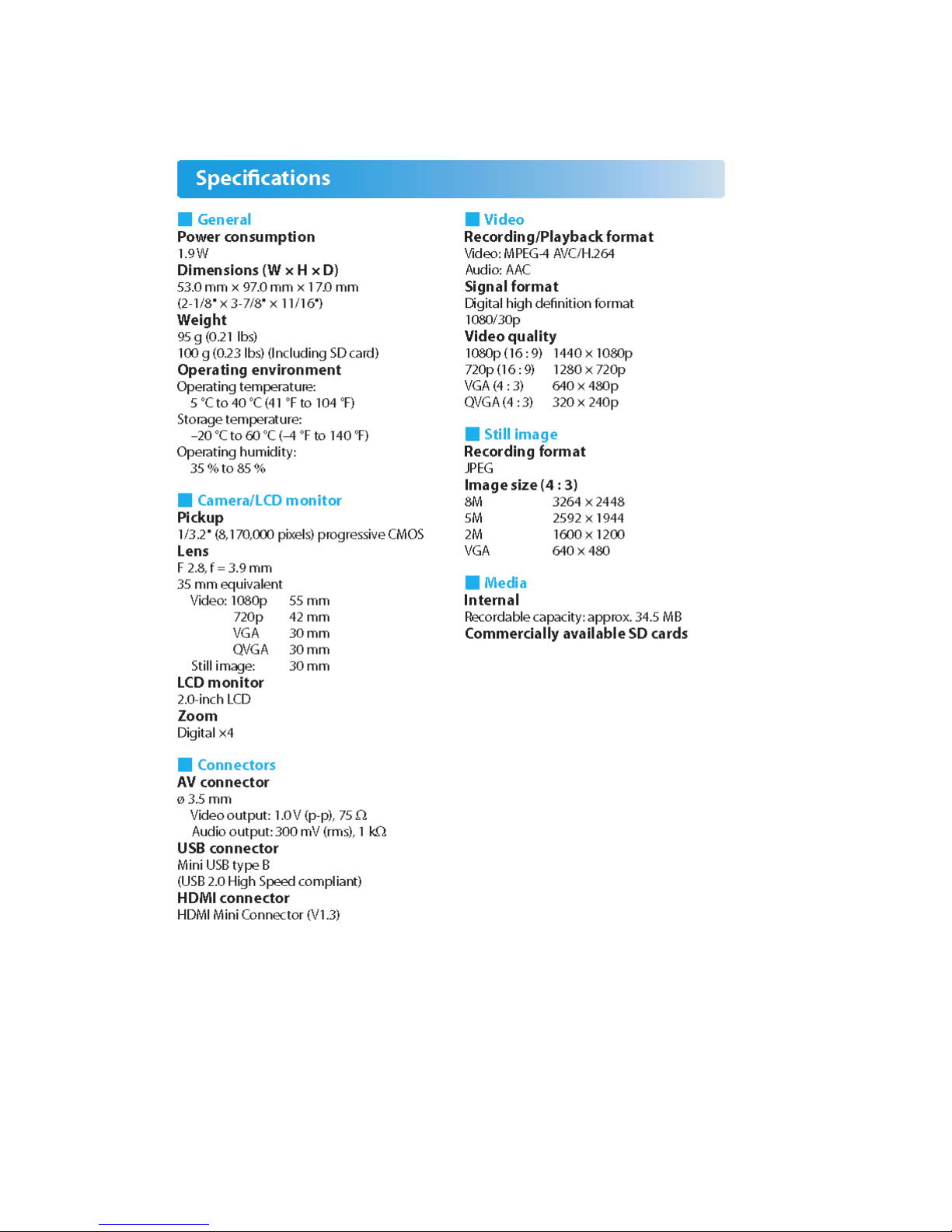
SPECIFICATION
1-2 (No.YF320<Rev.002>)
Page 3
SECTION 1
r
PRECAUTIONS
1.1 SAFETY PRECAUTIONS
Prior to shipment from the factory, JVC products are strictly
inspected to conform with the recognized product safety and
electrical codes of the countries in which they are to be
sold.However,in order to maintain such compliance, it is equally
important to implement the following precautions when a set is
being serviced.
1.1.1 Precautions during Servicing
(1) Locations requiring special caution are denoted by labels
and inscriptions on the cabinet, chassis and certain parts of
the product.When performing service, be sure to read and
comply with these and other cautionary notices appearing
in the operation and service manuals.
(2) Parts identified by the symbol and shaded ( ) parts
are critical for safety.
Replace only with specified part numbers.
NOTE :
Parts in this category also include those specified to
comply with X-ray emission standards for products
using cathode ray tubes and those specified for
compliance with various regulations regarding
spurious radiation emission.
(3) Fuse replacement caution notice.
Caution for continued protection against fire hazard.
Replace only with same type and rated fuse(s) as
specified.
(4) Use specified internal wiring. Note especially:
• Wires covered with PVC tubing
• Double insulated wires
• High voltage leads
(5) Use specified insulating materials for hazardous live parts.
Note especially:
• Insulation Tape
• PVC tubing
•Spacers
• Insulation sheets for transistors
• Barrier
(6) When replacing AC primary side components (transformers,
power cords, noise blocking capacitors, etc.) wrap ends of
wires securely about the terminals before soldering.
emission. Consequently, when servicing these products,
replace the cathode ray tubes and other parts with only the
specified parts. Under no circumstances attempt to modify
these circuits.Unauthorized modification can increase the
high voltage value and cause X-ray emission from the
cathode ray tube.
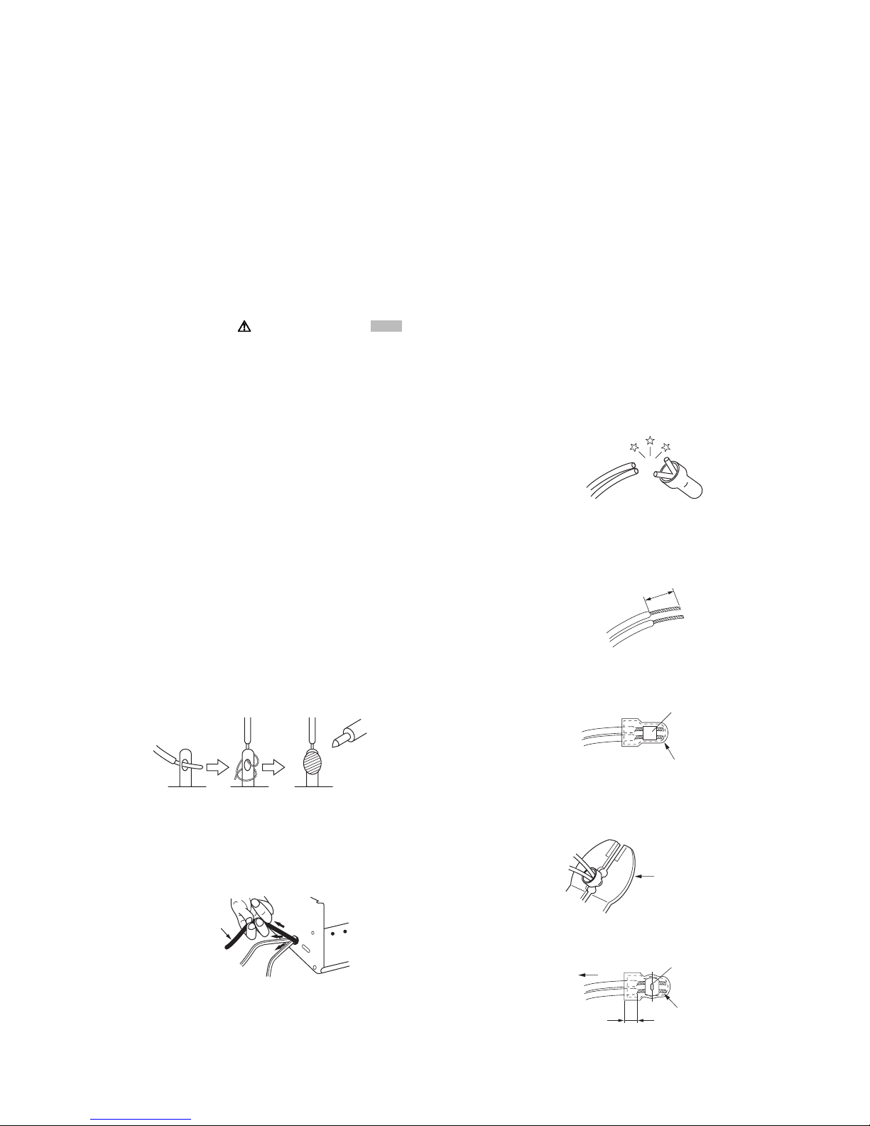
(12) Crimp type wire connectorIn such cases as when replacing
the power transformer in sets where the connections
between the power cord and power trans former primary
lead wires are performed using crimp type connectors, if
replacing the connectors is unavoidable, in order to prevent
safety hazards, perform carefully and precisely according
to the following steps.
• Connector part number :E03830-001
• Required tool : Connector crimping tool of the proper
type which will not damage insulated parts.
• Replacement procedure
a) Remove the old connector by cutting the wires at a
point close to the connector.Important : Do not
reuse a connector (discard it).
cut close to connector
Fig.1-1-3
b) Strip about 15 mm of the insulation from the ends
of the wires. If the wires are stranded, twist the
strands to avoid frayed conductors.
15 mm
Fig.1-1-4
c) Align the lengths of the wires to be connected.
Insert the wires fully into the connector.
Metal sleeve
Fig.1-1-1
(7) Observe that wires do not contact heat producing parts
(heatsinks, oxide metal film resistors, fusible resistors, etc.)
(8) Check that replaced wires do not contact sharp edged or
pointed parts.
(9) When a power cord has been replaced, check that 10-15
kg of force in any direction will not loosen it.
Power cord
Fig.1-1-2
(10) Also check areas surrounding repaired locations.
(11) Products using cathode ray tubes (CRTs)In regard to such
products, the cathode ray tubes themselves, the high
voltage circuits, and related circuits are specified for
compliance with recognized codes pertaining to X-ray
Connector
Fig.1-1-5
d) As shown in Fig.1-1-6, use the crimping tool to crimp
the metal sleeve at the center position. Be sure to
crimp fully to the complete closure of the tool.
1.2
5
2.0
5.5
Crimping tool
Fig.1-1-6
e) Check the four points noted in Fig.1-1-7.
Not easily pulled free
Wire insulation recessed
more than 4 mm
Crimped at approx. cente
of metal sleeve
Conductors extended
Fig.1-1-7
(No.YF320<Rev.002>)1-3
Page 4
1.1.2 Safety Check after Servicing
Examine the area surrounding the repaired location for damage
or deterioration. Observe that screws, parts and wires have been
returned to original positions, Afterwards, perform the following
tests and confirm the specified values in order to verify
compliance with safety standards.
(1) Insulation resistance test
Confirm the specified insulation resistance or greater
between power cord plug prongs and externally exposed
parts of the set (RF terminals, antenna terminals, video and
audio input and output terminals, microphone jacks,
earphone jacks, etc.).See table 1 below.
(2) Dielectric strength test
Confirm specified dielectric strength or greater between
power cord plug prongs and exposed accessible parts of
the set (RF terminals, antenna terminals, video and audio
input and output terminals, microphone jacks, earphone
jacks, etc.). See Fig.1-1-11 below.
(3) Clearance distance
When replacing primary circuit components, confirm
specified clearance distance (d), (d') between soldered
terminals, and between terminals and surrounding metallic
parts. See Fig.1-1-11 below.
d
Chassis
d'
Power cord
primary wire
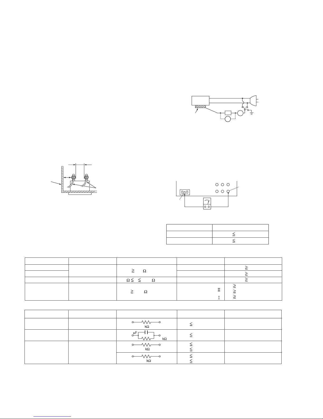
(4) Leakage current test
Confirm specified or lower leakage current between earth
ground/power cord plug prongs and externally exposed
accessible parts (RF terminals, antenna terminals, video
and audio input and output terminals, microphone jacks,
earphone jacks, etc.).
Measuring Method : (Power ON)Insert load Z between
earth ground/power cord plug prongs and externally
exposed accessible parts. Use an AC voltmeter to
measure across both terminals of load Z. See Fig.1-1-9
and following Fig.1-1-12.
ab
Externally
exposed
accessible part
Z
V
c
A
Fig.1-1-9
(5) Grounding (Class 1 model only)
Confirm specified or lower grounding impedance between
earth pin in AC inlet and externally exposed accessible
parts (Video in, Video out, Audio in, Audio out or Fixing
screw etc.).Measuring Method:
Connect milli ohm meter between earth pin in AC inlet and
exposed accessible parts. See Fig.1-1-10 and grounding
specifications.
AC inlet
Exposed accessible part
Fig.1-1-8
Earth pin
MIlli ohm meter
Grounding Specifications
Region
USA & Canada
Europe & Australia
Grounding Impedance (Z
Z 0.1 ohm
Z 0.5 ohm
)
Fig.1-1-10
AC Line Voltage
100 V
100 to 240 V
110 to 130 V
110 to 130 V
200 to 240 V
Region
Japan
USA & Canada
Europe & Australia
Insulation Resistance (R
R 1 M /500 V DC
1 M R 12 M /500 V DC
R 10 M /500 V DC
)
Dielectric Strength
AC 1 kV 1 minute
AC 1.5 kV 1 minute
AC 1 kV 1 minute
AC 3 kV 1 minute
AC 1.5 kV 1 minute
(
Class
(
Class
Clearance Distance (d), (d'
d, d' 3 mm
d, d' 4 mm
d, d' 3.2 mm
d 4 m m
)
d' 8 m m (Power cord
d' 6 m m (Primary wire
)
Fig.1-1-11
AC Line Voltage
100 V
110 to 130 V
110 to 130 V
220 to 240 V
Region
Japan
USA & Canada
Europe & Australia
Load Z
1
0.15
1.5
2
50
Leakage Current (i)
i 1 mA rms
i 0.5 mA rms
i 0.7 mA peak
i 2 mA dc
i 0.7 mA peak
i 2 mA dc
a, b, c
Exposed accessible parts
Exposed accessible parts
Antenna earth terminals
Other terminals
Fig.1-1-12
NOTE :
These tables are unofficial and for reference only. Be sure to confirm the precise values for your particular country and locality.
)
)
)
1-4 (No.YF320<Rev.002>)
Page 5
SECTION 2
SPECIFIC SERVICE INSTRUCTIONS
1.This camcorder has a built-in battery. The battery cannot be replaced by the user.
During disassembly/assembly, be careful not to get electrical
shock by touching and turning ON the power button, or not to
damage the circuits by short-circuiting.
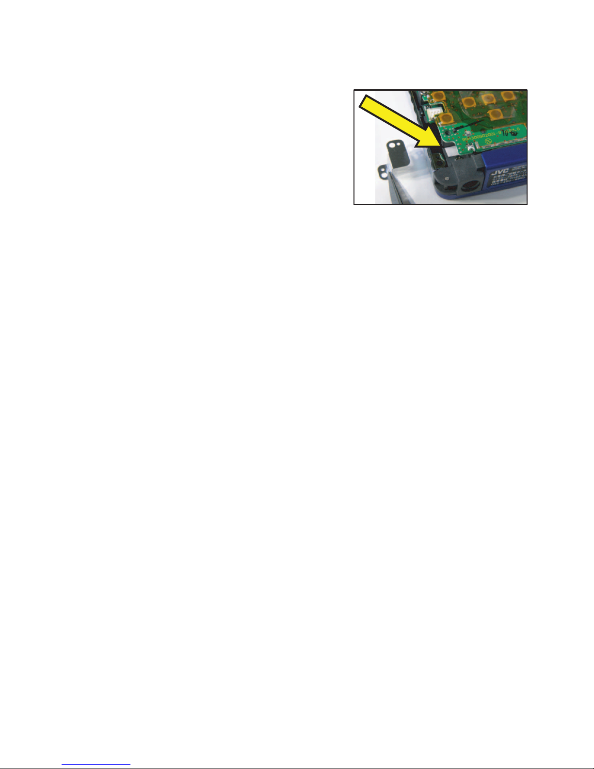
2.A water damage/submersion indicator (white) is affixed inside.(Refer to the picture in the right.)
When the battery is damaged by the water or submerged, the indicator turns to red.
3.When loading the battery to the main unit, be careful with the loading direction.
4.There is no adjustment needed after replacement of any parts.
5. Returning to the Factory Preset resets the following settings.
• File/ folder numbers
• Internal memory (image storage area) format
• Time setting
• Resolution setting
Procedure
(1) Download FN_Reset.dat from JS-NET.
Uploaded in "Special Tool" in "Service Support Software".
factory preset file for GC-FM1(31KB)
(2) Copy FN_Reset.dat to the SD card route.
(3) Insert the SD card into the slot on the main unit.
(4) Turn ON the power of the main unit.
(5) The power turns OFF automatically in about 1 second.
(6) Remove the SD card from the slot on the main unit.
NOTE
• If the remaining battery is less than half the capacity, a warning message appears and the reset cannot be performed.
• If a USB cable is connected for battery charging, the reset cannot be performed.
6. The firmware updated procedure is as follows.
(1) Download the relevant update file from JS-NET.
(2) Copy the update file to the SD card route.
(3) Insert the SD card into the slot on the main unit, then turn ON the power.
(4) An update screen appears.
(5) Selecting YES starts the update.
(6) When an update normal finish screen appears, turn OFF the power.
(7) Remove the SD card from the slot on the main unit.
7. The screw tightening torque is 0.108N*m (1.1kgf*cm) throughout the assembly procedure.
8. When the battery performance deteriorates, the following phenomena are observed.
• Abnormally long charging time
Normally, a completely empty battery finishes charging in about 3 hours. When the charging does not complete after about 6 hours
(twice the normal charging time), a battery trouble is considered.
If the charging does not complete after 12 hours, the charge LED blinks indicating an error.
• Abnormally short charging time
When a completely empty battery finishes charging in 10 to 20 minutes, battery abnormality is considered.
• Abnormally short discharge (usable) time
Although it varies according to environment, a fully charged new battery can record for about 70 minutes. If the battery becomes
empty (discharged) in several minutes, the battery capacity is considered to be extremely low.
9. Simple battery failure detection
When the voltage measures 2[V] or over between the (+) and (-) terminals, and the resistance measures 50[kΩ] to 150[kΩ] between
the (T) terminal and the GND, the battery is considered as a non defective battery.
(This does not indicate capacity decline. Use this measurement just as reference for detecting battery failure.)
(No.YF320<Rev.002>)1-5
Page 6

1-6 (No.YF320<Rev.002>)
Fig.2-1
Page 7

Fig.2-2
(No.YF320<Rev.002>)1-7
Page 8

1-8 (No.YF320<Rev.002>)
Fig.2-3
Page 9

SECTION 3
DISASSEMBLY
NOTE)The screw tightening torque is 0.108N·m (1.1kgf·cm) throughout the assembly procedure.
S1 : SCREW 1.7 x 4.0
S2 : SCREW 1.4 x 4.0
1
SCREW
(S1)
SCREW
(S1)
SCREW
(S1)
SCREW
(S1)
2 NOTE2
3 NOTE3
SCREW
(S1)
Unplug the battery power connector as shown
in the picture.
LCD
SCREW
(S1)
SCREW
(S2)4
PO
Pull the SPEAKER WIRES through the rib.
(No.YF320<Rev.002>)1-9
Page 10

4 NOTE4
Connector-Battery Wire
SCREW
(S1)
SCREW
(S1)
SCREW
(S1)
FPC Connector
B toB Connector
5 NOTE5
Place the SPEAKER WIRES as shown in the picture.
SCREW
(S1)
SCREW(S1)
SCREW
(S1)
Be careful with the FOCUS SWITCHING LEVER positioning.
Move both the LENS LEVER and the FOCUS SWITCHINGLEVER to the direction of the arrows before assembly.
SCREW
(S1)
SCREW
(S1)
Connector-Battery Wire
Connector-Battery Wire
6 NOTE6
SCREW
SCREW
SCREW
(S1)
(S1)
SCREW
(S1)
(S1)
SCREW
SCREW
(S1)
(S1)
1-10 (No.YF320<Rev.002>)
Place the battery wires within the guide as shown
in the picture.
Page 11

7 NOTE7
Push here to remove the battery.
This service manual does not describe ADJUSTMENT.
Be careful not to load the battery in a wrong direction.
SECTION 4
ADJUSTMENT
SECTION 5
TROUBLE SHOOTING
This service manual does not describe TROUBLE SHOOTING.
(No.YF320<Rev.002>)1-11
Page 12

Victor Company of Japan, Limited
Digital Imaging Products Business Division Imaging Products Operation 12, 3-chome, Moriya-cho, Kanagawa-ku, Yokohama-city, Kanagawa-prefecture, 221-8528, Japan
(No.YF320<Rev.002>)
Printed in Japan
VSE
Page 13

REVISION INFORMATION
HD MEMORY CAMERA
GC-FM1AUS, GC-FM1BUS, GC-FM1VUS,
GC-FM1AEU, GC-FM1BEU, GC-FM1VEU,
GC-FM1BAA, GC-FM1BAC
■ OVERVIEW
Parts have been added.
The additional parts are as follows:
Symbol Part No. Part Name
M1MM 25 1SM422700 GAP FILL TAPE
■ DETAILS
COVER SECTION
Title Line No.YF320<Rev.001> No.YF320<Rev.002> Description
Revision Rev.001 Rev.002
Issue Date 2009/10 2010/02
Copyright COPYRIGHT (C) 2009 Victor Company
of Japan, Limited
PARTS LIST
MODEL No. LIST
Model No. No.YF320<Rev.002>
GC-FM1AEU 04
GC-FM1AUS 01
GC-FM1BAA 07
GC-FM1BAC 08
GC-FM1BEU 05
GC-FM1BUS 02
GC-FM1VEU 06
GC-FM1VUS 03
FINAL ASSEMBLY [M1MM]
Symbol or
!
M1MM 25 ------------ 1SM422700 GAP FILL TAPE (Addition) 1 01,02,03,04,05,06,07,08
<Rev.001> <Rev.002>
Part No.
COPYRIGHT (C) 2010 Victor Company
of Japan, Limited
Part Name Description Qty Models
COPYRIGHT © 2010 Victor Company of Japan, Limited
YF320-R002
2010/02
Page 14

Victor Company of Japan, Limited
Digital Imaging Products Business Division Imaging Products Operation 12, 3-chome, Moriya-cho, Kanagawa-ku, Yokohama-city, Kanagawa-prefecture, 2218528, Japan
(YF320-R002)
Printed in Japan
No.YF320<Rev.001> VSE
Page 15

PARTS LIST
1.EXPLODED VIEW
1.1 FINAL ASSEMBLY <M1>
3-1
Page 16

2.PARTS LIST
2.1.FINAL ASSEMBLY<M1>
Symbol
No.
Part No. Part Name Q'ty
1 QA300-SVC001 FRONT COVER ASSY Including MIC 1
1 QA301-SVC001 FRONT COVER ASSY (BLUE) Including MIC 1
1 QA302-SVC001 FRONT COVER ASSY (PURPLE) Including MIC 1
2 QA300-SVC004 FRAME ASSY 1
3 QA300-SVC003 DOOR ASSY 1
3 QA301-SVC003 DOOR ASSY (BLUE) 1
3 QA302-SVC003 DOOR ASSY (PURPLE) 1
4 QA300-SVC005 SUB PCB ASSY 1
5 QA300-SVC002 REAR COVER ASSY 1
5 QA301-SVC002 REAR COVER ASSY (BLUE) 1
5 QA302-SVC002 REAR COVER ASSY (PURPLE) 1
6 QA300-SVC006 MAIN PCB ASSY 1
7 QA300-SVC007 MONITOR FRAME ASSY 1
8 XB00L00SN001 LITHIUM ION BATTERY 1
9 UDULCDTPD001 TFT LCD MODULE 1
10 1SM421928 STRAP PIN 1
11 1SM321303 OBI B 1
12 1SM422200 DATA PLATE (US) 1
12 1SM422292 DATA PLATE (US) BLUE 1
12 1SM422293 DATA PLATE (US) PURPLE 1
12 1SM422201 DATA PLATE (EU) 1
12 1SM422294 DATA PLATE (EU) BLUE 1
12 1SM422295 DATA PLATE (EU) PURPLE 1
12 1SM422203 DATA PLATE (AA) 1
12 1SM422204 DATA PLATE (AC) 1
12 1SM422202 DATA PLATE (JP) 1
12 1SM422296 DATA PLATE (JP) BLUE 1
12 1SM422297 DATA PLATE (JP) PURPLE 1
14 1SM421925 DOOR SHAFT 1
15 1SM421926 DOOR SP 1
16 1SM321363 EARTH PLATE 1
17 1SM321383 GND PLATE 1
18 1SM321448 GND PLATE B 1
19 1SM422341 THERMAL CONDITION SHEET A 1
20 1SM422360 THERMAL CONDITION SHEET C 1
23 1SM420609 SCREW.B-TIGHT 1.4*4.0 M3PAN+NI 4
24 1SM421116 SCREW.B-TIGHT 1.7*4.0 M3PAN+NI 14
2.2.ACCESSORY<M5>
Symbol
No.
Part No. Part Name Q'ty
-
WUU102SCP001 USB CABLE 1
- WPU122SCP001 AV CABLE 1
- 1SM422120 STRAP 1
- 1SM321404 BASIC USER GUIDE (US) * 1
- 1SM321423 BASIC USER GUIDE (EU) * 1
- 1SM321424 BASIC USER GUIDE (AA) * 1
- 1SM321425 BASIC USER GUIDE (AC) * 1
- 1SM321426 BASIC USER GUIDE (JP) * 1
* For more details on the operations, refer to the “Detailed User Guide” in the internal memory. (p. 4)
 Loading...