

Page 1
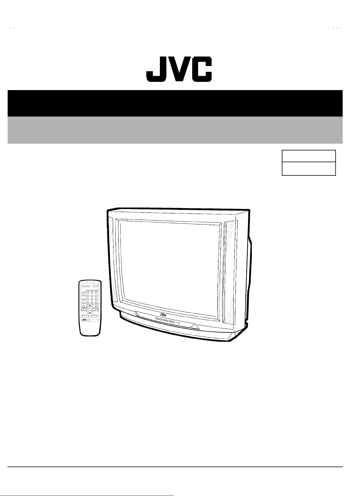
SERVICE MANUAL
COLOR TELEVISION
AV-T2922
BASIC CHASSIS
GA
AV-T2922
/AR
CONTENTS
! SPECIFICATIONS ・・・・・・・・・・・・・・・・・・・・・・・・・・・・・・・・
!
SAFETY PRECAUT IONS
!
FEATURES・・・・・・・・・・・・・・・・・・・・・・・・・・・・・・・・
! FUNCTIONS ・・・・・・・・・・・・・・・・・・・・・・・・・・・・・・・・
!
SPECIFIC SERVICE INSTRUCTIONS
! SERVICE ADJUSTMENTS ・・・・・・・・・・・・・・・・・・・・・・・・・・・・・・・・
★ STAND ARD CIRCUIT DIAGRAM (APPENDIX) ・・・・・・・・・・・・・・・・・・・・・・・・・・・・・・・・
! PARTS LIST ・・・・・・・・・・・・・・・・・・・・・・・・・・・・・・・・
1
・・・・・・・・・・・・・・・・・・・・・・・・・・・・・・・・・・・・・・・・・・・・・・・・・・・・・・・・・・・・・・・・
・・・・・・・・・・・・・・・・・・・・・・・・・・・・・・・・・・・・・・・・・・・・・・・・・・・・・・・・・・・・・・・・
・・・・・・・・・・・・・・・・・・・・・・・・・・・・・・・・・・・・・・・・・・・・・・・・・・・・・・・・・・・・・
・・・・・・・・・・・・・・・・・・・・・・・・・・・・・・・・・・・・・・・・・・・・・・・・・・・・・・・・・・・・・・・・
・・・・・・・・・・・・・・・・・・・・・・・・・・・・・・・・
・・・・・・・・・・・・・・・・・・・・・・・・・・・・・・・・・・・・・・・・・・・・・・・・・・・・・・・
・・・・・・・・・・・・・・・・・・・・・・・・・・・・・・・・・・・・・・・・・・・・・・・・・・・・・・・・・・・・・・・・
・・・・・・・・・・・・・・・・・・・・・・・・・・・・・・・・・・・
・・・・・・・・・・・・・・・・・・・・・・・・・・・・・・・・・・・・・・・・・・・・・・・・・・・・・・・・・・・・・・・・
・・・・・・・・・・・・・・・・・・・・・・・・・・・・・・・・・・・・・・・・・・・・・・・・・・・・・・・・・・・・・・・・
・・・・・・・・・・・・・・・・・・・・・・・・・・・・・・・・・・・・・・・・・・・・・・・・・・・・・・・・・・・・・・・・
・・・・・・・・・・・・・・・・・・・・・・・・・・・・・・・・
・・・・・・・・・・・・・・・・・・・・・・・・・・・・・・・・・・・・・・・・・・・・・
・・・・・・・・・・・・・・・・・・・・・・・・・・・・・・・・・・・・・・・・・・・・・・・・・・・・・・・・・・・・・・・・
・・・・・・・・・・・・・・・・・・・・・・・・・・・・・・・・・・・・・・・・・・・・・・・・・・・・・
・・・・・・・・・・・・・・・・・・・・・・・・・・・・・・・・・・・・・・・・・・・・・・・・・・・・・・・・・・・・・・・・
・・・・・・・・・・・・・・・・・・・・・・・・・・・・・・・・・・・・・
・・・・・・・・・・・・・・・・・・・・・・・・・・・・・・・・・・・・・・・・・・・・・・・・・・・・・・・・・・・・・・・・
・・・・・・・・・・・・・・・・・・・・・・・・・・・・・・・・・・・・・・・・・・・・・・・・・・・・・・・・・・・・・・・・
・・・・・・・・・・・・・・・・・・・・・・・・・・・・・・・・・・・・・・・・・・・・・・・・・・・・・・・・・・・・・・・・
COPYRIGHT © 2002 VICTOR COMPANY OF JAPAN, LTD.
・・・・・・・・・・・・・・・・・・・・・・・・・・・・・ 2
・・・・・・・・・・・・・・・・・・・・・・・・・・・・・・・・・・・・・・・・・・・・・・・・・・・・・・・・・・
・・・・・・・・・・・・・・・・・・・・・・・
・・・・・・・・・・・・・・・・・・・・・・・・・・・・・・・・・・・・・・・・・・・・・・
・・・・・・・・・・・・・・・・・・・・・・・・・・・・・・・・・・
・・・・・・・・・・・・・・・・・・・・・・・・・・・・・・・・・・・・・・・・・・・・・・・・・・・・・・・・・・・・・・・・
・・・・・・・・・・・・・
・・・・・・・・・・・・・・・・・・・・・・・・・・
・・・・・・・・・・・・・・・・・・・・・ 11
・・・・・・・・・・・・・・・・・・・・・・・・・・・・・・・・・・・・・・・・・・
・・・・・・・・・・・・・・・・・・・・・・・・・・・・・・・・・・・・ 31
・・・・・・・・・・・・・・・・・・・・・・・・・・・・・・・・・・・・・・・・・・・・・・・・・・・・・・・・・・・・・・・・
・・・ 4
・・・・・・
・・ 5
・・・・
・・・・・ 2- 1
・・・・・・・・・・
3
6
No.519 17
Mar. 2002
Page 2
A
V-T2922
)
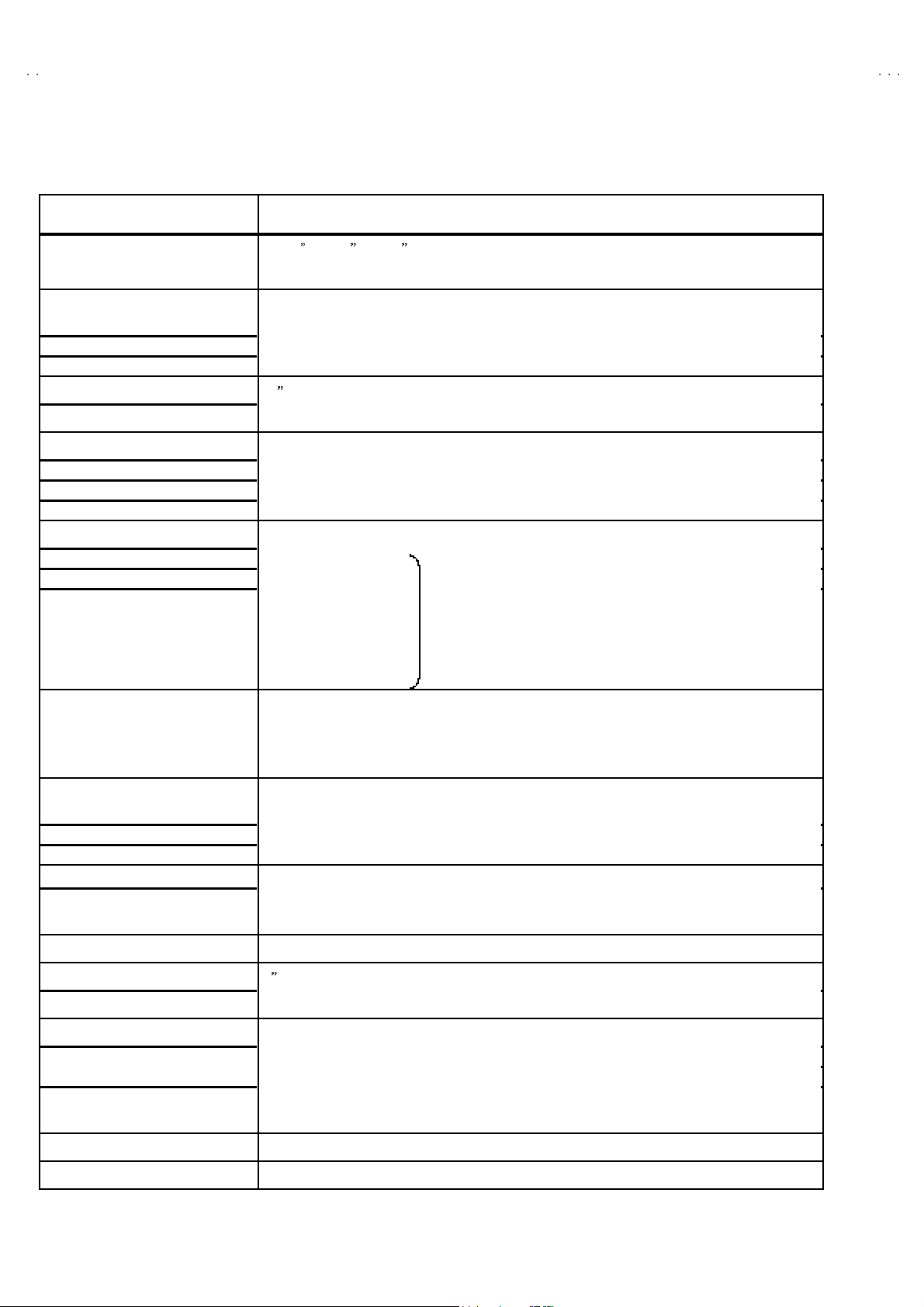
SPECIFICATIONS
Items Content
Dimensions (W××××H××××D) 29-5/8 ×23-1/4 ×20 -5/8 / 75.2cm×59.0 cm×52.2 cm
Mass 90.9Ibs / 41.3kg
TV System and Color system
TV RF System CCIR(M), CCT R(N)
Color System PA L-M / P AL- N / NTSC
Sound System BTSC (M ulti Channel S ound)
Picture Tube 29 (74 cm ) m easur ed di agonally, Full S quare
Hi gh V ol ta ge 29 kV±1.3 kV (at zer o beam cur rent)
TV Receiving Frequency
VL B and (02~06) 55 .25 MHz~83.25MHz
VH Ba nd (07~13) 1 75. 25MHz~21 1.25MHz
UH F Ba nd (14~69 ) 471. 25MHz~80 1.25MHz
CAT V Receiving Frequency
Low Band (02 ~06)
Hi gh B and (07 ~13)
Mid Band (14 ~22)
Super Band (23 ~36)
Hyper Band (37 ~64)
Ul tra Ba n d (65 ~94, 10 0~125)
Sub Mid Band (01, 96~99)
Intermediate Frequency
Video IF Carrier
Sound IF Carrier 41.25M H z (4.5MHz)
Color Sub Carrier
PAL-M 3.57561149MHz
PAL-N 3.5 8205625MHz
NT S C 3.579545MHz
Power Input
Opera ting Voltage 90V~260V A C, 50Hz/ 60Hz
Rated Voltage
Power Consumption 115W(max.) , 85W (avg.)
PICTURE : 45.75MHz
CHROMA : 42.17MHz
120V~24 0V AC , 50Hz/60Hz
(55.25MHz~79 9.25MHz)
Speaker 2×4-3/4” / 5×12cm Oval type×2
Audio Power Output 5W+5W
Input / Output terminals
Input 1, 2 (V, L/R
Variable Audio Output
Antenna terminal 75Ω(VHF/ UHF) Termi nal, F-Type Connecto r
Remote control unit RM-C363-1H (AA/R03/UM-4 dry cell battery×2)
Video : 1Vp -p , 75 Ω (RCA pin jack)
Au dio : 50 0mVrms ( -4dBs), Hi gh Imp edance (RCA p in jack)
More then 0~1550mVrms (+6dBs )
Low Impedance ( 400 Hz w hen modulated 100%) (RCA pin j ack)
Design & specifications are subject t o change wit hout notice.
2
No.51917
Page 3

A
2
SAFETY PRECAUTIONS
V-T292
1. The d esign of th is pr od uct con tains special hardware , ma ny
circuit s and components specially for saf ety purposes. For
con tinu ed pr ot ection, n o changes shou ld be made to the o riginal
desi gn un less a uth or i zed in w riting by the manu facturer.
Replacement p ar ts must b e id ent ic al to thos e u sed in the origi n al
ci rcu it s. S er vic e sho uld be performed by qu al if ied pers on nel
only.
2. Alterations of t he desig n or cir cuitry of t he prod ucts sh ould not be
made. Any design alterations or additions will void the
manufact urer 's warr a nt y and will f urth er relieve t he ma nu factu r er
of resp onsibility for perso na l injur y or property dam ag e r esult ing
th erefr om.
3. Man y electr ical an d m ech anica l parts i n the prod ucts ha ve
special safety-related characteristics. These characteristics are
oft en no t e viden t f rom visua l i nspection n or can t he pr o tect io n
aff or de d by th em necessari ly be ob tain ed by using rep lac ement
com po ne nts rated for hig he r vol tag e, watt ag e, etc. Rep l acement
parts wh ic h have these speci al s afety ch aract erist ics are
identified in the parts list of Service m anual. El ectric al
components having such features are identifi ed by shading
on t he sche matic s and b y (!!!! ) on the parts list in Service
manual. The us e of a sub stitute r ep lacem en t whi ch does n ot
have the sam e saf ety ch ar act erist ics as the reco mmen de d
replac em ent par t sh own in the parts li st of Ser vice manual may
cause shock, fire, or other hazards.
4. Don't shor t between the LIVE side ground and ISOL ATED
(NE UTRAL) side ground or EARTH side ground when
repairing.
Some model's power circuit is partly different in the GND. The
diff erenc e of th e G ND is shown b y th e LIVE : (") side GND, the
ISO LATE D(NEUTRAL) : (#) side G ND and EAR TH : ($) side
GND. Do n't short bet ween th e LIVE sid e GND an d
ISO LATE D(NEUTRAL) side GND or EARTH side GND an d
never m ea sure wit h a m ea suring apparatus (oscil loscop e etc.)
th e LI VE sid e GN D and IS OLATED(NEUTRAL ) side G ND or
EARTH side GND at th e s ame time.
If above note will not be kept, a fuse or any parts will be broken.
5. If any repair has been made to the chassis, it is recommended
th at t he B1 setting should b e ch ecke d or adjusted (See
ADJUSTMENT OF B 1 POWE R SUPPL Y).
6. The hi gh voltage applie d t o th e pi cture tu be must con form w it h
th at speci fi ed i n S er vice manual. Excessive h igh voltage ca n
cau se an incr e ase in X-R ay emission , ar cing an d possible
component damage, therefore operation under excessive high
voltage conditions should be kept to a minimum, or should be
preve nt ed. If s ever e arc ing occurs, r em ove t he AC power
immed iate l y and determine the ca use by visua l insp ection
(incorrect in stallat ion, cr acke d or melted high vo lt age harness,
poor so ld ering, et c.). To maint ain the p r ope r minimu m level of
sof t X- Ray em i ssion, c omponents in the high voltag e cir cuitry
including the pict ur e tube must be t he e xact r ep lacem e nts or
alternat ives approve d b y th e ma nuf act urer of th e c omplete
product.
7. Do not c heck hi gh volt age by dr awing an arc. U se a high voltag e
meter or a high v oltag e pr ob e wit h a V T VM . D ischarge th e
picture tube before attempting meter connection, by connecting
a cl ip lead to th e gr ou nd frame and conn ecting the oth er end of
the lead through a 10kΩ 2W resisto r to the an od e butt on .
8. When se r vice is requ ired, obser ve th e or igina l lea d dr ess. Extr a
prec aut ion sh ou ld b e g iven t o assure cor r ect lead dress in the
high voltag e cir cuit area. W her e a s hort ci r cuit has occu rred,
th ose co mp on ent s tha t indi cate evi de nce of overheating sho ul d
be replace d. Alwa ys use th e manuf act urer's r ep lacem en t
components.
9. Isolation Check
(Safety for Electrical Shock Hazard)
Af ter re-ass emb ling the p r odu ct, always perf orm an isolation
ch eck on the expo sed metal parts of t he cabin et (ante nn a
termina ls, video /audio inpu t and ou tput t ermin als, Control kn obs,
metal cab ine t, screw h eads , ear p ho ne j ac k, c ont rol shaft s, etc .)
to be sure th e p rodu ct is s af e t o o perate without d an ger of
elect rical shoc k.
(1) Dielectric Strength Test
The isolation between the AC prima ry circuit and all me tal p arts
exp osed t o th e user, p articul arly an y expos ed metal part havi ng a
return path to the chass is sho uld withs tan d a vol t age of 3 000 V
AC (r.m.s.) for a period of one second.
(. . . . W it hstand a vo lt ag e of 1 10 0V A C (r.m.s.) to an applianc e
rated up to 12 0V, an d 3 00 0V AC (r .m.s.) to an applian ce r at ed
200V or more, for a period of one second.)
This method of test requires a t est equipment n ot generally found
in the ser vice trad e.
(2) Leakage Current Check
Plug th e A C line c ord d irect ly in to the AC outlet (do not use a lin e
isolation transf ormer during this ch eck.). Using a " Lea kage
Curr ent Tester", measure th e leakag e curre nt f rom each exposed
metal part of the ca bi ne t, particu larly any e xpos ed metal part
havi ng a r e tur n path to t he ch ass is , to a kn ow n go od ea rt h
ground (wa ter pip e, etc.). An y l eakage cur r en t m ust n ot e xceed
0.5mA AC (r.m.s.).
However, in tropic al area, th is must no t exceed 0.2 mA AC
(r.m.s.).
"""" Alternate Ch e ck M ethod
Plug th e A C line c ord d irect ly in to the AC outlet (do not use a lin e
isolation tran sformer dur ing t hi s che ck.). Use an AC vo ltmeter
havi ng 1 00 0 oh ms per volt or more sens itivity in the fo llow ing
manner. Connec t a 1 500Ω 10W res istor paralle le d b y a 0.1 5µF
AC-type capacit or bet ween an expo sed met al part and a known
good earth gro un d (water pipe, etc.). Meas ur e the AC vo lt ag e
acr oss th e res ist or with th e AC voltmeter. Move the resistor
con nec ti on to e ach exp ose d me tal par t, p art icul ar ly any exp osed
metal part havi n g a r etu rn pat h to t he ch assis , an d m easure the
AC voltag e ac ross the res ist or . No w, rever se th e plug in th e AC
outlet and re pe at eac h mea surem en t. An y volt ag e me asured
must no t exceed 0.75V AC (r.m.s.). This c orre spo nds to 0.5mA
AC (r.m.s.).
Howeve r, in tropica l area, this must not exce ed 0.3V AC ( r .m.s.).
This corresponds to 0.2mA AC (r.m.s.).
AC VOLT METER
(HAVING 1000 Ω /V,
OR MOR E SENSIT IVITY)
0.15μF AC-TYPE
PLACE THIS PROBE
1500 Ω 10W
GOOD EARTH GROUND
ON E A C H EX PO SE D
ME T AL PA R T
No.51917
3
Page 4
A
V-T2922
FEATURES
" The stable image proces sing ci rcui t wh ic h is al ready acknowledged en ables p owerfu l image expression by t he 29 in ch big scr een.
"
Multifunct ion al remote con trol p ermits picture adjustment.
"
With AUDIO / VIDEO inpu t termina l.
" Variable aud io outpu t termina l.
" Ad opti on of the VIDEO STATUS f unc tion .
"
Ad option of the SLEEP TIMER f unction .
"
With 75ΩV/U i n c ommon (F-Type) antenna terminal.
"
Wide range voltage (120V~240V) AC power i npu t.
"
I2C bus control utilizes single chip ICs.
" Built-in HYPER SURROUND system.
"
CLOSED CAPTION broadcasts c an be viewed.
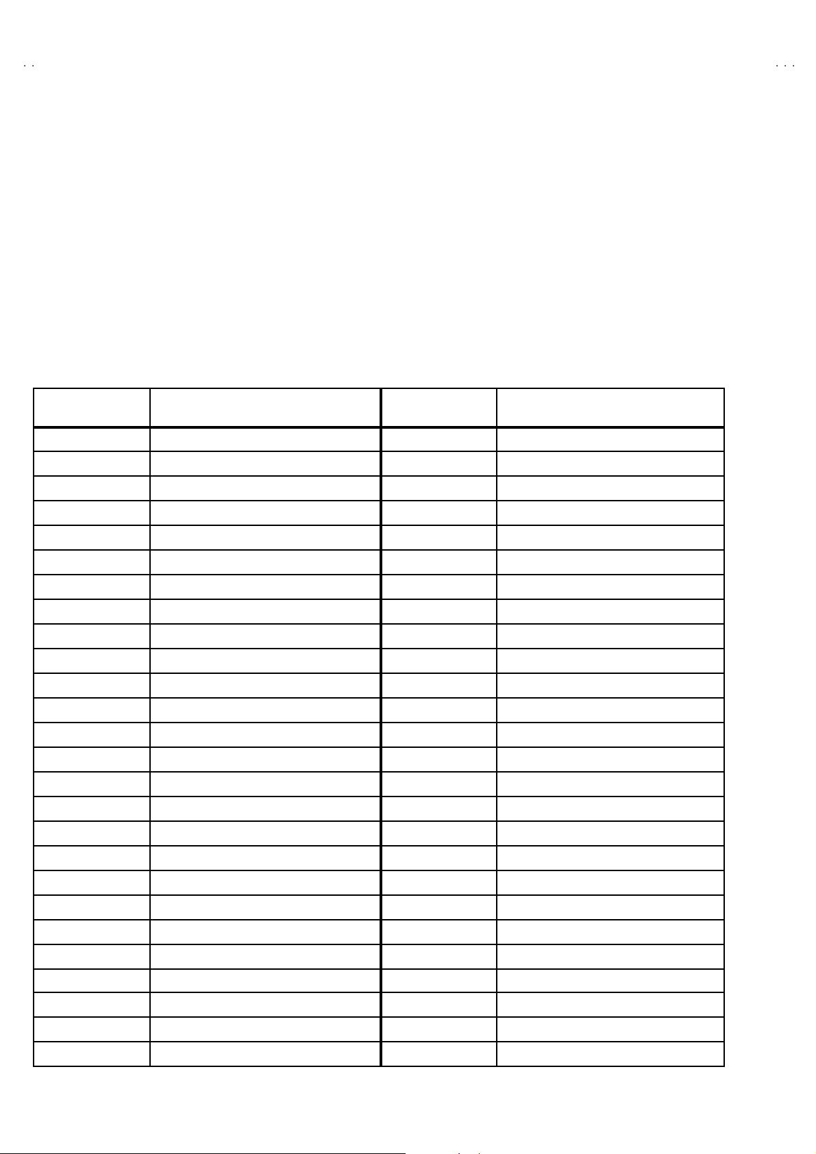
MICR O COMPUTER PORT ASSIGNMENT (IC701)
PORT NUMBER PORT FUNCTION PORT NUMBER PORT FUNCTION
1 H SYNC 27 Vcc
2 V S YNC 28 OSC1
3 RF AFC 29 OSC2
4 REMOCON 30 RESE T
5 NECK 31 POW ER ON/OFF
6 SD 32 ENAB LE
7 T ON/O FF 33 CLOCK
8 KE Y2 34 DATA
9 KE Y1 35 LO CK
10 SP ON/OFF 36 SDA2
11 NC 37 SDA1
12 NC 38 SCL2
13 NC 39 SCL1
14 AUDIO MUTE 40 Ym
15 I2C H/S 41 BUS FREE
16 NC 42 NC
17 NC 43 SELECT1
18 A Vcc 44 SELECT2
19 HLF 45 AGC MUTE
20 RVCO 46 AGC ADJUST
21 V HOLD 47 TV / EXT
22 Composite VIDEO IN 48 X-RA Y / OCP
23 CN Vss 49 Ys
24 X IN 50 B
25 X OUT 51 G
26 Vss 52 R
4
No.51917
Page 5
A
2
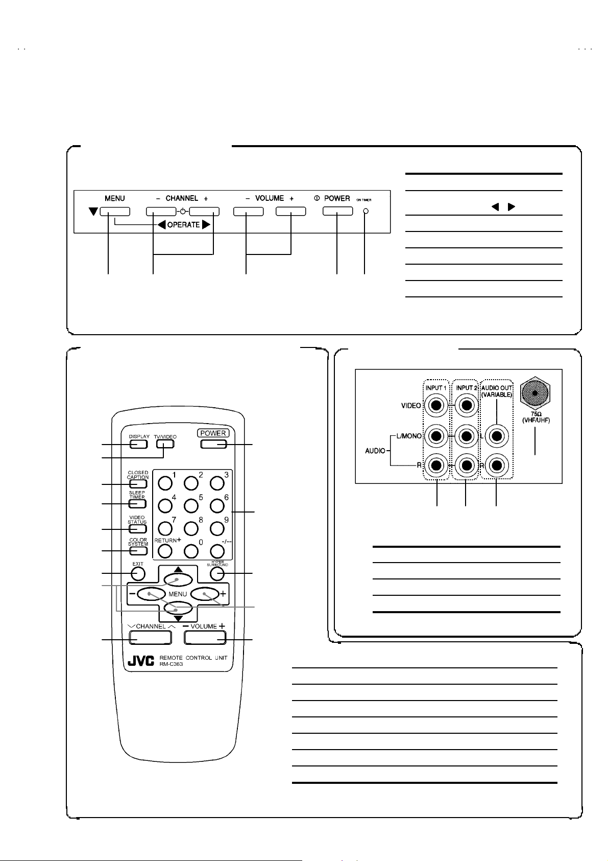
FUNCTIONS
FRONT CONTROL KEYS
①①①①②
②③
②②
① MENU / OPERATE ▼ key
②
③
④
⑤
③④
③③
④⑤
⑤
④④
⑤⑤
REAR TERMINALREMOTE CONT RO L UNIT (RM-C363)
CHANN EL ― /+ or
OPERATE / keys
VOLUME ― /+ keys
POWER button
LED (indicator)
・・・・
Red
Green・・On Timer indication
Power indication
V-T292
①①①①
②②②②
③③③③
④④④④
⑤⑤⑤⑤
⑥⑥⑥⑥
⑦⑦⑦⑦
⑫⑫⑫⑫
⑧⑧⑧⑧
⑨⑨⑨⑨
⑩⑩⑩⑩
⑪⑪⑪⑪
⑬⑬⑬⑬
⑭⑭⑭⑭
③③③③②②②②①①①①
①
INPUT 1 (V, L/R ) terminal
②
INPUT 2 (V, L/R ) terminal
③
VARIABLE AUDIO OUT (L/R) terminal
④
Aerial socket (F-type connector)
① DISPLAY key ⑧ CH ANNEL ▲/▼ key
②
TV / VIDEO key
③
CLOSED CAPTION key
④
SLEEP TIMER key
⑤
VIDEO STATUS key
⑥
COLOR SYSTEM key
⑦ EXIT key ⑭ VOLUME -/+ key
⑨
POWER button
⑩
CHANN EL NUMBER key
⑪
HYPER SURROUND key
⑫
ME NU ▲/▼ key
⑬
MENU - / + key
④④④④
No.51917
5
Page 6

A
V-T2922
SPECIFIC SERVICE INSTRUCTIONS
DISASSEMBLY PROCEDURE
REMOVING THE REAR COVER
1. Unplug the po wer plu g from AC ou tlet.
2. As shown in F ig. 1, remove t he 11 screws marked
screws marked "
Note:
When reinstalling the rear cover, carefully push it inward after
inserting the chassis into the rear c over groove.
".
""
!!!!
and 2
REMOVING THE CHASSIS
" After removing the rear cover.
1. Sli ght l y raise t he bot h si de s of th e chassis by hand and remove
th e 2 claw s under the b oth si d es of the chassis f rom the fr ont
cab inet .
2. Draw the c hassi s backwa rd al ong t he ch assi s rail in the ar row
direction marked #
(If necessary, remove t he wire clamp, connectors etc.)
Note:
When con ducting a c heck with p ower su pplied, be s ure t o conf irm
th at the CRT earth wire is certainly co nn ecte d.
# as s hown in the Fi g. 1.
##
CHECKING THE MAIN PW BOARD
To check the backside of t he MA IN PW Bo ard.
1) Pu ll out the chassis. ( Refer to REMOVING THE CHASSIS ).
2) Erect the chassis vertically so that you can easily check the
backside of the MAIN PW Board.
[CAUTION]
"
When erecting the chassis, be careful so that there will be no
con tact in g with ot her PW B .
" Before turning on power, make sure that the CRT earth wire
and oth er con nector s are prop erly conn ected.
WIRE CLAMPING AND CABLE T YING
1. Be sure to clamp the wire .
2. Never r emo ve the c able ti e used f or tying the wi re s togethe r.
Should it be inadvertently removed, be sure to tie the wires with a
new cable tie.
REMOVING THE SPEAKER
" After removing the rear cover and chassis.
1. As s hown in Fi g.1 , rem ove th e 4 screws marked $
2. Foll ow th e s ame st eps when rem oving the other hand spe aker.
$.
$$
6
No. 51917
Page 7

A
2
FRONT CABINET
V-T292
CRT
SP EAKE R
D
CRT SOCKET PWB
(Within MAIN PWB)
MAIN PWB
FRONT CONTROL PWB
CLAW
SP EAKE R
REAR COVER
D
CLAW
C
B
A
POWER CORD
Fig. 1
No. 51917
7
Page 8

A
V-T2922
SYS
S
O
G
S
CC
S
O
S
U
S
O
SOU
US
O
S
)
VIDEO
MEMORY IC REPLACEMENT
1. Memory IC
This model uses a memory IC.
The memory IC stores data for proper operation of video/chroma and deflection circuits.
When replacing, be sure to use the IC c ontai nin g initia l setting d ata .
2. Memory IC replacement procedure
PROCEDURE
(1) Power off
Switch off the p ower and disconnec t the power pl ug from t he out let.
(2) Replace the memory IC.
Be sur e to use th e m emory IC writt en with t he in itial set ting values.
(3) Power on
Connect the power plug t o the outlet and sw it ch on the po wer.
(4) System constant check and setting
It must not adjus t without signal.
1) Sim ul ta neo usly pr ess the DISPL AY key and VI DEO ST ATU S key
of th e rem ot e control unit.
2) The SERV ICE M EN U screen is d isp layed as sh own in Fig .1.
3) Whil e t he SERVICE MENU is disp layed , ag ain si multaneo usly
press the DISPLAY an d VI DE O ST ATU S keys to display t he
SY STEM CONSTAN T screen as shown i n Fig. 2.
4) Refer to th e S YSTEM C ON STANT t able and ch eck the s etting
items. W her e th ese diff er, select the sett in g ite m with t he MENU
▼▼▼▼
/
keys an d a dj ust the sett in g with t he MENU
(The le tters of t he s elect ed it em ar e displ a yed in ye llow.)
5) When adjust me nt has completed, pres s th e MENU ―――― / ++++ key to
store the setting value.
6) Press the EX IT key twic e to return to th e normal screen.
――――
/
++++
▲▲▲▲
keys.
ERVICE MEN
PICTURE
VID EO STA T
RF AFC CHK VCO (CW
I2C BUS CTRL
ELECT BY
PERATE BY
TEM CONSTANT
AM E : YE
D: YE
VID E
ELECT BY
PERATE BY
ND
THER
EX IT BY
Fig.1
: 2
EX IT BY
Fig.2
EXIT
EXIT
IT
IT
(5) Receiving channel setting
Refer to th e OPERATING INS TRUCTIONS (USER’S GUIDE) and
set the rece ive ch ann els ( Cha nn els Pr eset) as desc ribed.
(6) User setting s
Check th e user s etting items according to th e Table 2 given pag e
later.
Where thes e do n ot agree, refer t o the O PERATING
INSTRUCT IONS (USER’S GU ID E) an d s et t he it ems as desc rib ed.
(7) SERVIC E MENU s etti ng
Verif y what to s et in the SERVICE MENU, and set whatever is
necessary. (Fig.1) refer to the SERVICE ADJUSTMENT for setting.
8
DISPLAY
STATUS
EXIT
MENU
UP/DOWN
MENU
LEF T/RIGHT
No. 51917
Page 9

A
2
VALUES OF SYSTEM CONSTANT (TABLE1)
Setting item Setting content Setting value
V-T292
GAME YES
HYPE R S CAN YES
SURROUND YES
CCD YES
VIDEO 2
YES NO
YES NO
YES NO
YES NO
210
VALUES OF USER SETTING ITEMS (TABLE2)
Setting item Setting value
Settings of switches on front panel and remote control unit
MAIN POWE R OFF
SUB P OWER ON
CHA N NE L CH 02
CHA NNEL PRESET Refe r to O PERATING INSTR UCTIONS
VOLUME 10
TV/V IDEO TV
DISPLA Y OFF
SLEEP TIME R 0
VIDEO STATUS ES TANDAR
CLOSED CAPTIO N NO (CC1/T1)
HYPER SURROUND NO
Settings of MENU screen
TINTE ESTANDER
COLOR ESTANDER
CONTRASTE ESTANDER
BRILLO ESTANDER
DETALLE ESTANDER
GRAVES CENTER
AGUDOS CEN TER
BALANCE CENTER
MTS ESTEREO
ALTAVOCES SI
AJU STE DEL RELOJ Unn ecess ary to set
TEMPORIZADOR NO
LIS TA DE CANAL ES Unnecess ar y to set
ADJUSTECÓ DIGO DE ACCES O Unnecessary to set
PROGRAMACI ÓN AUTOMÁTICA Unnecessary to set
MO DE TV
PANTALLA AZUL N O
SUBT ÍTULOS OCUILTOS SUBTÍTULOS : CC1 TEXT0 : T1
IDIOMA ES P.
No. 51917
9
Page 10

A
V-T2922
REPLACEMENT OF CHIP COMPONENT
CAUTIONS
1. Avoid heating for more than 3 seconds.
2. D o n ot ru b the electrodes and t he resist p arts of th e patt ern.
3. W hen r em oving a chip part, melt th e solder ad equate ly.
4. D o n ot r euse a ch ip part after remo ving it .
SOLDERING IRON
1. U se a high ins ulatio n soldering iron with a thin pointed e nd of it .
2. A 30w s oldering iron is rec omm end ed for easil y removing parts.
REPLACEMENT STEPS
1. How to remove the Chip parts
Resi stors, ca pacitors , et c
(1) As shown in t he f ig ure, pu sh th e pa rt with tweezer s and
alternat ely melt th e solder at each end.
(2) Shift with tweeze rs and remove the ch ip part.
Trans isto rs, dio des, va riable r es ist or s, et c
(1) Apply e xtra so lder to ea ch le ad.
SOLDE R
SOLDE R
2. How to install Chip parts
Resi stors, ca pacitors , et c
(1) Apply sold er to th e pattern as indicated in the fig ure.
(2) Grasp the ch ip part with tweezer s and plac e it on the s ol d er.
The n hea t and melt the so ld er a t b oth ends of t he chip part.
Trans isto rs, dio des, va riable r es ist or s, et c
(1) Apply sold er to th e pattern as indicated in the fig ure.
(2) Grasp th e chip part wit h tweezers and p lace it on the so lder.
(3) First solder lead A as indicated in the figu re.
A
(2) As shown in t he f ig ure, pu sh th e pa rt with tweezer s and
alternat ely melt th e solder at each le ad. S hi ft and remove t he
chip part.
Note : A fter removing t he part, remove remain ing so lder fro m the
pattern.
10
C
(4) The n solder leads B and C.
A
C
No.51917
B
B
Page 11

A
2
SERVICE ADJUSTMENT
BEFORE STARTING SERVICE ADJUSTMENT
1. There ar e 2 w ay of ad ju s ti ng t hi s TV: One i s wi th t h e
REMOTE CONTROL UNI T and the other is the conventional
method using adjustment parts and components.
2. The adjustment with the REMOTE CONTROL UNIT is made
on the b asis of the init ia l sett ing values. The setting va lues
which adjust the screen to its optimum condition may differ
from t he init ial setting v al ues.
3. Make s ur e th at conn ect ion is c orrect l y made t o AC power
source.
4. Turn on t he p ow er of th e se t and equipmen t bef or e use, an d
start the ad justmen t proc edures af ter wai ti n g at least 30 min utes.
5. U nless ot her wis e spec if i ed, pr ep ar e th e mo st suitable r ec epti o n
or inp ut signal for adjust ment.
6. N ev er touch a ny adjustme nt p art s, whi ch ar e not sp e cif ied
in the li st f or thi s adjust me nt VR s , transf or ms, condenser s,
etc.
7. Prep arati o n for adjustment
Unless otherwise specified in the adjustment instructions, preset
the following functions with the REMOTE CONTROL UNIT.
User menu preset value
VIDEO STATUS ESTANDAR
TINTE, COLOR, CONTRASTE,
BRILLO, DETAL LE
GRAVES, AUGD OS , BALANCE
HYPE R SURR OUND
V-T292
MENU ITEM PR ES ET VALUE
ESTANDAR
CENTER
NO
MEASURING INSTRUMENT AND FIXTURES
1. DC voltmeter (or digital voltmeter)
2. Oscilloscope
3. Si gn al gen erat or (P att ern g ener at or) [ PAL- M / PA L-N / NTSC]
4. Remote control unit
5. TV aud io multipl e x sign al generator
6. F requ enc y cou nte r
ADJUSTMENT ITEMS
BASIC ADJUSTMENT
! Check of B1 pow er supp l y
!
IF VCO adjustment
! FOCUS adjustment
!
RF AGC ad ju stment
DEFLECTION CIRCUI T ADJUSTMENT
!
V. HE IGHT
! V. POSI TION
!
V. LINEARITY
! V S CORRECTION
!
H. POSITION
VIDEO / CHROMA CIRCUIT ADJUSTMENT
! WHITE BA LANCE ~LOW LIGHT~
! WHITE BA LANCE ~HIGH L IGHT~
! SUB BRI GHT
!
SUB CONTRAST
! SUB COL OR
!
SUB TI NT
MTS CIRCUIT ADJUSTMENT
!
INPUT LEVEL
! STEREO VCO
! SAP VCO
!
FILTER
! SEPARATIO N
No. 51917
11
Page 12

A
V-T2922
(
)
ADJUSTMENT LOCATIONS
FRONT
F 901
FRONT CONTROL PWB
TOP
CRT SOCKET PWB
(Wi thi n MAIN P WB)
++--
VO LU ME CH ANNEL
P
PW
POWER
SW
MAIN PWB
S
IC 702
MEMOR Y
P
T
MENU
TP-R
T
N
FRONT
N
IC 701
SOLDER SI DE
TP-E( )
U
E1
CR T EAR TH
(BRAIDED ASS'Y)
DEG
MPX
TUNER
T11 1
CW
1Pin : B1 (TP-91)
2Pin : NC
3Pin : T P-E ( )
HV
HVT
HVT
U
B1
13
HVTHVT
UPPER : FOCUS
LOWER : SCREEN
12
No. 51917
Page 13

A
2
BASIC OPERATION SERVICE MENU
C C
)
1. TOOL OF SERVICE MENU OPE RATION
Operate the SERVICE MENU with the REMOTE CONTROL UNIT.
2. SE RVICE MENU ITEMS
With the SERVICE MENU, various settings (adjustments) can be made, and they are broadly classified in the following items of
adjustments.
(1) PICTURE ・・・・・・・ ・・・・・・・・・ This mode adjusts the VIDEO / CHROMA and DEFLECTION circuits.
(2) SOUND ・・・・・・・ ・・・・・・・・・・・ This m od e adjust s th e AUDIO circuits.
(3) VI DEO STA TUS ・・・・・・・ ・・・・This mode adjust s th e THEATE R an d G AME m ode.
(4) OTHERS・・・・・・・ ・・・・・・・・・・ Thi s mod e adj ust s the OTHERS mode .
(5) LOW LIGHT・・・・・・・ ・・・・・・・ This mode adjust s th e whit e balan ce (low light) mode.
(6) HIGH LIGHT・・・・・・・ ・・・・・・・ This m od e adjust s th e whit e b alance ( high lig ht) m ode.
(7) RF AFC CHK
(8) VCO(C W) ・・・・・・・・・・・・・・・・ This mode adjusts the IF VCO mode.
(9) I2C BUS CTRL
・・・・・・・ ・・・・・・
・・・・・・・ ・・・・・
This mode adjusts the IF VCO mode. [Do not adjust]
This mode is u sed whe n necessary to ad just the on/off of the I2C bus control. [Do not adjust. Fixed on]
V-T292
3. BASIC OPERATION OF SERVICE MENU
(1) Ho w to enter SERVICE MENU
Press the DI SPLAY key and the VI DE O S TAT U S key of the
REMOTE C ON TROL UNIT simu lt an eou sly, an d the
SERVICE MENU screen will be displayed (Fig.1).
(2) Selection of SUB MENU SCREEN
In SERVICE MENU, pr ess th e MENU ▲▲▲▲ /▼▼▼▼ key to select
any of the fo llowin g item s. (The le tters of the select ed ite ms
are displayed in yell o w)
●PICTURE ●SOUND
●VIDEO STA TUS ●OTHERS
●LOW LIGHT ●HIGH LIGHT
●RF AFC CHK ●VCO(CW )
2
●I
C BUS CTRL
SE RVICE M ENU
SERVICE MENU
PIC TURE SOUN D
VID EO STATUS O THERS
LOW LIGHT HIGH LIGHT
HK VCO (CW
RF AF
I2C BUS CTRL
SELECT BY
O PERAT E BY
Fig.1
KEY ASSIGNMENT OF REMOTE CONTROL UNIT
DISPLAY
VIDEO
STATUS
EXIT
EXIT BY
EX IT
IT
MENU
UP/DOWN
MENU
LEF T/RIGHT
No. 51917
13
Page 14

A
V-T2922
A
CU
(3) Method of Setting
1) MENU ▲▲▲▲ / ▼▼▼▼ key
Se lect t he se tting ite m.
2) MENU ―――― / ++++ key
Se tti ng the set ting valu e of th e set ting item.
When ch ange the v a lues, automatic ally stored in the memory.
3) EX IT key
Return t o th e pr evious screen.
NOTE
In PICTURE MODE, hhile the color of letters displayed yellow, you can
adjust the values. If letters displayed red, you cannot adjust.
(4) Release of SERVICE MENU
After co mpleting t he adjustment, return to the main SERVI CE MENU by
pressin g the EXIT key. Th en ag ain p r ess the EXIT key, retur n to t he normal
screen.
Select it em
1. PI CT URE
**** ****
**** ****
**** ******** ****
SELECT BY
OPERAT E B Y
1. NOI SE
STANTUS
STANTUS
STANTUSSTANTUS
SELECT BY
OPERAT E B Y
djustment value
PICTURE MODE
***
***
******
****
****
********
EXIT BY
EX IT
***
***
******
****
****
********
EXIT BY
EX IT
IT
IT
The letter of the selected
Items are displayed in yellow.
TINT G DRI V E
COLO R B DRIVE
PIC TURE R CUT.
BRI GHT G CUT.
DETA IL B CUT.
SELECT BY
OPERAT E B Y
THEATER
***
***
******
***
***
******
***
***
******
***
***
******
***
***
******
***
***
******
***
***
******
***
***
******
***
***
******
***
***
******
EXIT BY
EX IT
IT
Press
VIDEO
STA TUS
VIDEO STA TUS MODE
Key
SOUND MODE
1. OSD POS.
**** ****
**** ******** ****
SELECT BY
OPERAT E B Y
OTHERS MODE
TINT G DRI V E
COLO R B DRIVE
PIC TURE R CUT.
BRI GHT G CUT.
DETA IL B
SELECT BY
OPERAT E B Y
***
***
******
***
***
******
***
***
******
***
***
******
***
***
******
GAME
T.
***
***
******
****
******** ****
********
EXIT BY
EX IT
***
***
******
***
***
******
***
***
******
***
***
******
***
***
******
EXIT BY
EX IT
IT
IT
14
No. 51917
Page 15

A
V-T292
2
SERVICE MENU (MAIN MENU)
SE RV ICE M EN U
PICTURE SOUND
VIDEO STATUS OTHERS
LOW L IGH T HIGH LI GHT
RF AFC CHK VCO (CW)
I2C BUS CTRL
SE LEC T BY
OPERATE BY
EX IT BY
EXIT
IT
HIG H LIGHT MOD E
HIGH LIGHT
** *
** *
** *** *
** *
** *
** *** *
EX IT BY
EXIT
IT
RF AFC CHK MODE [D O NOT ADJ UST]
SE LEC T BY
EX IT BY
EXIT
PICTURE MODE
1. PICTURE
** ** *** *
** ** *** *
** ** *** *** ** *** *
IT
SE LEC T BY
OPERATE BY
** **
** **
** **** **
EX IT BY
EXIT
** *
** *
** *** *
IT
OTHERS MODE
** *
1.OS D POS.
** ** *** *
** ** *** *
** ** *** *** ** *** *
SE LEC T BY
OPERATE BY
** **
** **
** **** **
EX IT BY
EXIT
** *
** *** *
IT
SOU ND MOD E
RF AFC
FINE
STATUS
SE LEC T BY
OPERATE BY
** *** ***
** *** ***
** *** ***** *** ***
** *** ***
** *** ***
** *** ***** *** ***
EX IT BY
VOC (CW) M ODE
V CO ( CW )
TOO HIGH
ABOVE REFERENCE
BELOW REFERENCE
TOO LOW
SY NC : YE S
EX IT BY
I2C BU S CTRL MO DE [FIXED ON ]
I 2C B US O N
OPERATE BY
EX IT BY
** *
** *
** *** *
EXIT
EXIT
EXIT
ON
1. NOISE
STATUS
IT
SE LEC T BY
OPERATE BY
** *
** *
** *** *
** *** ***
** *** ***
** *** ***** *** ***
EX IT BY
EXIT
IT
VID EO STATUS MODE
THEATER
** *
TINT G DRIVE
COLOR B DRIVE
PICTURE R CUT.
BRIGHT G CUT.
DETAIL B CUT.
IT
SE LEC T BY
OPERATE BY
** *
** *** *
** *
** *
** *** *
** *
** *
** *** *
** *
** *
** *** *
** *
** *
** *** *
** *
** *
** *** *
** *
** *
** *** *
** *
** *
** *** *
** *
** *
** *** *
** *
** *
** *** *
EX IT BY
EXIT
TINT G DRIVE
COLOR B DRIVE
PICTURE R CUT.
Press
VID EO
STATUS
IT
Ke y
BRIGHT G CUT.
DETAIL B CUT.
SE LEC T BY
OPERATE BY
** *
** *
** *** *
** *
** *
** *** *
** *
** *
** *** *
** *
** *
** *** *
** *
** *
** *** *
GAME
** *
** *
** *** *
** *
** *
** *** *
** *
** *
** *** *
** *
** *
** *** *
** *
** *
** *** *
EX IT BY
EXIT
IT
LOW LIGHT MODE
** *
BRIG H T
IT
BRIGHT
** *
** *** *
** * *** * **
** * *** * **
** * *** * **** * *** * **
EX IT BY
EXIT
IT
No. 51917
15
Page 16

A
V-T2922
INITIAL SETTING VALUE OF SERVICE MENU
1. Ad justment of the SE RVICE MENU is ma de on the ba sis of the initial setting v alue s. Howev er, t he new s ett ing values which set the
screen in its optimum condition may differ from the initial setting.
2. Do not change the in itial sett ing values of t he a djustment ite ms not list ed in “ADJU STM ENT” page s.
PICTURE MODE
The four s etting items in the video mode No.8 EX T PIC., No .9 EXT BRI., No.10 EXT COL., and No.11 EX IT TINT are linked to the items in t he
TV MODE No.1 PICTURE, No.2 BRIG HT, No.5 COL.NTSC and No.6 TINT, resp ectively. When the sett ing items in the TV mo de are adjusted,
th e values in th e setting items i n t he video mode are revis ed au tomat ic all y to th e same va lues in th e TV mode .( The initia l sett ing val ues given
in ( ) a re off -set valu es. )
When th e f our ite ms (No. 8, 9, 1 0 a nd 11) are ad juste d in t he video mode, the setting valu es in each item are revise d in dep en de ntly.
No . Setting (Adjustment) item Variable range Initial setting val ue
1. PICTURE 0~127 60
2. BRIGHT 0~127 64
3. COL. PALM 0~127 80
4. COL. PA LN 0~127 80
5. COL. N TSC 0~127 95
6. TINT 0~127 65
7. TV DTL 0~63 33
8. EXT PI C. ±25 (0)
9. EXT BRI. ±25 (0)
10. EXT CO L. ±25 (+4)
11. EXT T INT
12. EXT DTL 0~63 30
13. P/N K ILL 0 / 1 0
14. Y S CONT 0~31 31
15. TV Y- DL 0~41
16. EXT Y-DL 0~41
17. WPL SW 0 / 1 0
18. Y GAMMA 0 / 1 0
19. P/N G P. 0 / 1 0
20. COL. L SW 0 / 1 1
21. COL. LMT. 0~31
22. PN C. ATT 0~31
23. OFST. SW 0 / 1 0
24. OFST. B-Y 0~15 8
25. OFST. R-Y 0~15 8
26. C-TOF SW 0 / 1 1
27. TV T FO 0~31
28. TV T Q 0~30
29. EXT T FO 0~30
30. EXT T Q 0~30
31. C-TRAP 0 / 1 0
32. C-TR . FO 0~32
33. C-TRAP Q 0~31
34. FIX B/W 0 / 1 0
35. AP A P. FO 0~32
36. DC TRAN. 0~74
37. B. ST. SW 0 / 1 0
38. B. ST. PO. 0~70
39. AB L GA IN 0~74
40. AB L PO. 0~70
41. HALF T.
42. DRV G S W 0 / 1 0
43. NT. COMB 0 / 1 1
44. COIN DET 0~33
45. NOISE L.
46. VCD MODE 0 / 1 0
47. V AGC S P 0 / 1 0
48. H POS . 50 0~31 6
49. H BL K. 50
50. V POS. 50 0~72
±25
0~2
0~3
0~7
(+3)
1
3
0
16
No. 51917
Page 17

A
2
PICTURE MODE
G
No . Setting (Adjustment) item Variable range Initial setting val ue
51. V SIZE50 0~127 71
52. V S CR50 0~127 83
53. V LIN. 50 0~31 4
54. H POS. 60 0~31 10
55. H BL K. 60 0~70
56. V POS. 60 0~70
57. V SIZE60 0~127 72
58. V S CR60 0~127 99
59. V LIN. 60 0~31 3
60. RF AGC 0~255 160
SOUND MODE
No . Setting (Adjustment) item Variable range Initial setting val ue
1. NOISE 0 / 1 1
2. IN LE VEL 0~63 50
3. FH MON . 0 / 1 0
4. ST VCO 0~63 25
5. PILOT 0 / 1 0
6. FILTER 0~63 30
7. LOW SEP. 0~63 22
8. HI SEP. 0~63 23
9. 5FH M ON. 0 / 1 0
10. SA P VCO 0~63 26
11. IN GAIN 0 / 1 0
12. FIL. OFF. 0~10 0
V-T292
VI DEO STA TUS MODE
Setting (Adjustment) item Variable range
TINT ±20 0 0
COLOR
PICTURE -30~+20 -10 -10
BRIGHT
DETAIL ±15 0 -5
G DRIVE -99~+50 -22 0
B DR IVE -99~+50 -54 0
R CUT.
G CUT. ±10 0 0
B CUT.
Initial set ting v alue
THEATER
±
20 -3 -3
±
20 0 0
±
10 0 0
±
10 0 0
AME
No. 51917
17
Page 18

A
V-T2922
OTHERS MODE
No . Setting (Adjustment) item Variable range Initial setting val ue
1. OSD P OS. 0~31 7
2. LO CK DET 0 / 1 0
3. SD SE L. 0~20
4. H-CK SW 0 / 1 0
LOW LIGHT MODE
Setting ( Adj ustment) item Variabl e range Initial setting val ue
R CUTOFF 0~255 20
G CUTOFF 0~255 20
B CUTOFF 0~255 20
HIGH LIGHT MODE
Setting ( Adj ustment) item Variabl e range Initial setting val ue
G DRIVE 0~255 128
B DR IVE 0~255 128
RF AFC CHK MODE
Setting ( Adj ustment) item Variabl e range Initial setting val ue
RF AFC ON / OFF ON
FINE -77~+77 ±××
I2C BUS CTRL MODE
Setting ( Adj ustment) item Variabl e range Initial setting val ue
I2C BUS ON / OFF [Fi xed ON ]
DO N OT
AD JUST
18
No. 51917
Page 19

A
2
ADJUSTMENTS
)
)
BASIC ADJUSTMENT
Item
Check o f
B1 POWER
SUPP LY
Measuring
instrume nt
DC Voltmet er TP- 91
Test point Ad justment item Description
(B1 connector
1 p i n)
TP-E(#)
(B1 connector
3 pi n )
1. R eceive a black an d white si g nal (colo r off ). (NTSC)
2. C on nect the DC vo lt me ter to B 1 c onnector 1 pin ( TP-91) and
TP-E(#) (B 1 connect or 3 pin).
3. C onf ir m th at the vol ta ge is DC129.5 V V .
+2
-2.5
V-T292
IF VCO
adjus tment
Signal
generator
Remote
control unit
VCO (CW
TOO HIGH
TOO LOW
EX IT BY
EXIT
CW TRANSF. (T111
VCO (CW) mode
YE LLOW
IT
"
Under normal conditions, no adjustment is required. And it must
not a djust wit hout signal.
1. R eceive th e NTSC b roadc ast.
2. Select t he VCO(CW ) mode from the SER V IC E M EN U.
3. It c hecks that turn the CW TRANSF and the character of “TOO
HIGH” changes to yellow.
4. N ext, it chec ks th at tu rn the CW TRAN SF on th e cont rary and
“TOO LOW” ch anges to yellow.
5. At this time, it checks that “SYNC” is “YES” .
6. Turn the CW TR ANSF and it is made f or th e c h aract er of
“BELOW REFERENCE” to become yellow. Again, it checks
that “SYNC” is “YES”.
FOCUS
adjus tment
Signal
generator
FOCUS VR
[In HVT]
No. 51917
1. Receive a crosshatch signal.
2. W hile looking at th e sc re en, adj u st FOCUS VR so th at the
vertical and horizontal lines will be clear and fine in a detail.
3. M ake sur e t hat th e pict ur e is i n f ocus even w he n t he screen
gets darken ed.
19
Page 20

A
V-T2922
Item
RF AGC
Ad j ust men t
Measuring
instrume nt
Remote
control unit
Test point Adjustment part Description
No .60 R F AG C 1. R eceive an y bro adcast..
2. Select “No.60 RF AGC” of the PICTURE MODE in SERVICE
ME NU.
3. Pr ess the MUTING key an d tur n off t he colo r.
4. Wi th th e MENU ―――― key, g et noise in t he screen picture. (Zer o
si de of sett in g value)
5. Pr ess the MENU ++++ key and stop when noise d is app ea rs fr o m
th e scre en.
6. Change t o oth er chann els and ma ke sur e th at th ere is no
irregularity.
7. Pr ess the MUTING key and get color out.
Setting It e m Variabl e range Init ial set ting v alue
No .60 R F AG C
0~255
160
20
No. 51917
Page 21

A
2
DEFLECTION CIRCUIT ADJ USTMENT
The setting (adjustment) using the remote control unit is made on the basis of the initial setting v alues.
The setting values which adj ust the screen to the optimum condition can be different from the initial setting val ues.
V-T292
Item
60 Hz
PAL -M or
NT SC signal
adjus tment
V. HE IGHT
V. POSI TION
V. LIN
V. S CR
adjus tment
Screen
size
92%
Measuring
instrume nt
Signal
generator
Remote
control unit
Picture size 100%
Test point Ad justment part Description
No .56 V POS. 60
No .57 V S IZE 60
No .58 V S CR60
No.59 V. LIN. 60
Screen size
Picture
size
100%
1. Receive a crosshatch signal.(NTSC or PAL-M)
2. Conf irm t ha t the va lu e of PICTURE MODE “No. 56 V PO S. 60”
is 0.
3. Conf irm th e initia l sett ing value of the “No.57 V SI ZE 6 0”, No. 58
V S CR60” an d “No. 59 V L IN. 60” .
4. Ad ju st t he vertical screen s ize to 92 % with the PICTURE
MODE “No. 57 V SIZE60”.
5. Ad ju st t he PI CTURE MODE “No. 59 V LIN. 60” and “No.58 V S
CR60” to get the best vertical linearity.
NOTE :
"
The PICTURE MODE “No.56 V POS. 60” is fixed on value 0.
"
Bottom of scr een is t o be located within the 85%~95% range.
ADJU STM ENT ITEM INITIAL SETTING VALUE
No .56 V POS. 60 00(Fixed on)
No .57 V S IZE 60 72
No .58 V S C R 60 99
No.59 V. LIN . 60 03
50 Hz
PAL-N signal
adjus tment
V. HE IGHT
V. POSI TION
V. LIN
V. S CR
adjus tment
Signal
generator
Remote
control unit
No .50 V POS. 50
No .51 V S IZE 50
No .52 V S CR50
No .53 V LI N. 50
1. Recei ve a cr oss hat ch sig na l. (P AL -N)
2. Conf irm the ini ti al s ettin g valu e of the “No.5 0 V POS. 50”,
“No.51 V SI ZE 50 ” , “ No. 52 V S C R 50” and “No. 53 V LIN.50 ”.
3. Adjust the vertical screen size to 92% with the PICTURE
MODE “No. 51 V SIZE50”.
4. Ad ju st th e PICT URE MODE “No. 53 V LIN.50 ” and “No.52 V S
CR50” to get the best vertical linearity.
5. Ad ju st t he PICTURE MODE “No. 50 V POS .50 ” s o t ha t the
ver ti cal center c omes clos e to the CRT vertical ce nter as much
as possib le.
6. Readjust V SIZE, V LIN . and V S CR if ne cess ary.
NOTE :
"
Bottom of screen is t o be located within th e 85%~95% range.
ADJU STM ENT ITEM INITIAL SETTING VALUE
No .50 V POS. 50 02
No .51 V S IZE 50 71
No .52 V S C R 50 83
No.53 V. LIN . 50 04
No. 51917
21
Page 22

A
V-T2922
Item
60 Hz
PAL -M or
NT SC signal
adjus tment
H. P OS ITIO N
adjus tment
Measuring
instrume nt
Signal
generator
Remote
control unit
HH"
Test point Adjustment part Description
No .54 H POS .60 1. Receive a crosshatch sign al. ( NTSC or PAL- M)
2. Se lect the “No. 54 H P OS. 60” of th e PI CTURE mod e in
SERVICE MENU.
3. C onf ir m th e initial sett in g value of the "No. 54 H PO S. 6 0".
4. Ad ju st th e “No. 54 H P OS. 60” unt il the screen will be
horizont ally c entered.
ADJU STM ENT ITEM INITIAL SE TTING VALUE
No .54 H POS . 6 0 10
50 Hz
PAL-N signal
adjus tment
H. P OS ITIO N
adjus tment
Signal
generator
Remote
control unit
No .48 H POS .50 1. Receive a crosshatch signal. (PAL-N)
2. Se lect the “No. 48 H P OS. 50” of th e PI CTURE mod e in
SERVICE MENU.
3. C onf ir m th e initial sett in g value of the "No. 48 H PO S. 5 0".
4. Ad ju st th e “No. 48 H P OS. 50” unt il the screen will be
horizont ally c entered.
ADJU STM ENT ITEM INITIAL SE TTING VALUE
No .48 H POS . 5 0 06
22
No. 51917
Page 23

A
2
VIDEO / CHROMA CIR CUIT ADJUSTMENT
The adjustment usi ng the remote control unit is made on the basis of the initial setting values.
The setting values which adj ust the screen to the optimum condition can be different from the initial setting val ues.
Do no t c hang e the initial se tting values of t he setting it ems not listed in “A DJUSTMENT”.
V-T292
Item
WHITE
BALANCE
(Low Light)
adjus tment
R CUTOFF
Measuring
instrume nt
Signal
generator
Remote
control unit
LOW LIGHT MODE
BRIGHT
*** *** ***
*** *** ***
*** *** ****** *** ***
BRI GHT
Test point Ad justment item Description
BR IG HT
1. Receive a black-and-whi t e sign al.( Color off)
2. Select t he LOW LIGHT MODE from the SERVI CE ME NU.
R CUTOFF
G CUTOFF
B CUTOFF
3. Se t the ini ti a l se tting valu e of BRIG HT w it h th e MENU ―――― / ++++
key of the remote control unit.
4. Se t the init ial sett in g value of R CUTO FF, G CUT OFF an d B
SCREEN VR
CUT OFF with the ④④④④ to ⑨⑨⑨⑨ key of the remote control unit.
5. Disp lay a sing le horizont al line by p r essing th e ①①①① key of the
remote control unit.
6. Tur n t he scr een VR a ll the way t o the left.
7. Turn t he screen VR gradually to th e r ight f rom the left un ti l
either one of the r ed, bl u e or g reen co lors appea rs f aintly.
8. Use ke ys ④~⑨ of the remote control un it and adjus t the
oth er 2 colors whi ch except th e appeared c ol or to w h er e the
G CUT OF F
si ng le horiz ont al line appea rs white.
9. Turn the screen VR to where the sing le hor i zontal li ne gl o ws
BRIGHT
faintly.
10 . Press the ②②②② key t o r eleas e the single horizont al line.
***
***
******
EXIT BY
EX IT
B C U TO FF
IT
11. Ad just th e BRIGHT level to bec om e the black co mponent
shines white slightly.
12. Conf irm th at whet her the color ing redient of R , G or B is vi sibl e
to th e bl ack component which sh ines white slig htl y.
13. When th e c olor ingredien t can be seen, tw o color s oth er th an a
visible color are adjusted, and it is made to look white.
14 . Return th e value of BRIGHT to initial setting value.
15 . Press the EX IT key to exit th e WHITE BALANCE MODE.
KEY ASSIGNMENT OF REMOTE CONTROL UNIT
SIN GLE LINE ON
123
SIN GLE LINE OFF
9
G .CU TO FF ( )
B. CUT OFF( )
B. CUT OFF( )
B. DRI VE(
R. CU TOF F( )
R. DR IVE ( )
R. CU TOF F( )
R. DR IVE (
△
△△
4
7
△
△
)
R
56
8
GB
△
B. DRI VE( )
G .CU TO FF ( )
△
△
△
)
△
No. 51917
C UT O FF ADJ USTM E NT
R
G
B0
Variabl e
range
0 ~255
0 ~255
~
255 20
Initial set ting
value
20
20
23
Page 24

A
V-T2922
Item
WHITE
BALANCE
(High Light)
adjus tment
SUB BRI GHT
adjus tment
Measuring
instrume nt
Signal
Gene rator
Remote
control unit
HIGH LIGHT MODE
Remote
control unit
Test point Ad justment item Description
G DRIVE
B DR I VE
1. R eceive th e NTSC b lack a nd white s ig nal (c olor of f) .
2. Select t he HI GH LIG HT mode in the SER VI CE ME NU.
3. Confirm the initial setting value of “G DRIVE” and “B DRIVE”.
4. Ad ju st t he scr e en color to wh it e w it h t he ⑤⑤⑤⑤ , ⑥⑥⑥⑥, ⑧⑧⑧⑧ and ⑨⑨⑨⑨
keys of the remote control unit.
B DRIVEG DRIVE
HIGH LIGHT
***
*** ***
******
***
******
EXIT BY
EX IT
IT
DR I VE AD J USTM E NT
G
B
No.2 BRIG HT 1. Receive a N TSC broadca st.
2. Se le ct “No.2 BRIGHT” of th e PI CTURE mode in SERVICE
ME NU.
3. C onf ir m th e initial sett in g value of the “No.2 B RI GH T” .
4. If the brightness is no t th e best with the initial settin g value ,
make f in e adj us tment of the “No. 2 B RI GH T” until you g et the
optimum bri ght ness .
Variabl e
range
0 ~ 25 5
0 ~ 25 5
Initial set ting
value
128
128
SUB
CONT RAST
adjus tment
Remote
control unit
BR IG HT A DJ US T M ENT
No.2 BRIGHT
No .1 P I C T UR E 1. Receive a NTSC br oa dcast.
2. Se le ct “No. 1 PICTURE ” of the PICT URE m od e in S ER VICE
ME NU.
3. C onf ir m th e initial sett in g value of the “No.1 P IC TURE” .
4. If the contr ast is not the best with the initial sett ing value, make
fine adjustm ent of t he “No. 1 PICTURE” un ti l you ge t th e
optimum contrast.
PICTURE
ADJUSTMENT
No.1 PICTURE
Variabl e
range
0 ~ 12 7
Variabl e
range
0 ~ 12 7
Initial set ting
value
64
Initial set ting
value
60
24
No. 51917
Page 25

A
V-T292
2
Item
SUB COLOR
adjus tment
Measuring
instrume nt
Remote
control unit No .3 COL . PALM
Test point Ad justment item Description
No.4 COL . PALN
No .5 COL . NT SC
[PAL-M]
1. R eceive a PA L- M broa dcast.
2. Select “No. 3 COL . PALM” of th e P ICT URE mod e i n SER VICE
ME NU.
3. C onf ir m th e initial sett in g value of the “No.3 COL. PALM” .
4. If the color is not the best with the initial setting value, make
fine adjustment until you get the best color.
[PAL-N]
1. R eceive a PA L- N broadc ast.
2. Select “No. 4 CO L. PA LN” of th e PIC TURE mo de in SE RVIC E
ME NU.
3. C onf ir m th e initial sett in g value of the “No.4 COL. PA LN”.
4. If the color is not the best with the initial setting value, make
fine adjustment until you get the best color.
[NTSC]
1. R eceive a NTSC br oa dcast.
2. Select “No. 5 COL . N TSC” of th e P ICT URE mod e in SERVICE
ME NU.
3. C onf ir m th e initial sett in g value of the “No.5 COL. NTSC”.
4. If the color is not the best with the initial setting value, make
fine adjustment until you get the best color.
SUB TINT
adjus tment
Remote
control unit
COLOR ADJUSTMENT
No.3 COL. PAL-M
No.4 COL. PAL-N 0 ~ 127 80
No.5 COL. NTSC
No . 6 TINT 1. Receive a NTS C color bar sig nal.
2. Select “No. 6 TINT” of the PICTURE mode in SERVICE
ME NU.
3. C onf ir m th e initial sett in g value of the “No. 6 TI NT”.
4. If the tin t is not th e best with the initial se tting value, make fine
adjustment until you get the best tint.
TINT ADJUSTMENT
No.6 TINT
Variabl e
range
0 ~ 12 7
0 ~ 12 7
Variabl e
range
0 ~ 12 7
Initial set ting
value
80
95
Initial set ting
value
65
No. 51917
25
Page 26

A
V-T2922
[
]
[
]
[
]
[
]
cycle
MTS CIRCUIT ADJUSTMENT
Item
MTS INPUT
LEVE L
che ck
MTS
STEREO VCO
adjus tment
Measuring
instrume nt
Remote
control unit
Signal
generator
Frequency
counter
Remote
control unit
R OUT
Test point Ad justment part Description
No.2 IN LE VEL 1. Se le ct t he “ No.2 IN LEVEL” of th e SOUND mode in SERVICE
ME NU.
2. Verify that the “No.2 IN LEVEL” is set at its initial setting
value.
AUDIO OUT
No.3 FH MON
No.4 ST VCO
1. R eceive a NTSC R F sign al (non modula ted sou nd sign al) from
th e a nte nna t ermin al.
2. Select the “No.3 FH MON” of SOUND mode in SERVICE
MENU, cha nge the setting va lue from 0 to 1.
3. Connect th e fr eq uen cy connect or t o R O UT RCA pi n of the
AUDIO OUT.
4. Select t he “ No.4 ST VCO”.
5. C onf ir m th e initial sett in g value of the “No.4 S T VCO”.
6. Adjust t he “No.4 ST VCO ” so that t he freq uency co un ter wil l
display 15.73kHz±0.1 kHz.
7. Select t he “ No.3 FH MON” of the SOUND m od e, and reset the
set ting value from 1 to 0.
MTS SAP
VCO
adjus tment
MTS FILTER
che ck
MTS
SE PAR ATIO N
adjus tment
-
Signal
generator
Frequency
counter
Remote
control unit
Remote
control unit
TV audio
Multiplex
signal
generator
Oscillo scope
Remote
control unit
MPX
Connector
4 pi n SDA
3 pi n GN D
MAIN PW B
R OUT
AUDIO OUT
L OUT
R OUT
AUDIO OUT
No .9 5 F H M ON.
No .10 SAP VCO.
No .6 FILTER
No.7 LOW S EP.
No.8 HI S EP.
-
1. R eceive a NTSC R F sign al (non modula ted sou nd sign al) from
th e a nte nna t ermin al.
2. C on nect b et we en pi n 4 of MP X co nn ector and GND (pin 3 of
MPX co nnecto r) t hr ou gh 1M Ω resistor.
3. Select t he “ No.9 5 FH MON.” of the S OU ND mode in SERV ICE
MENU, and r eset t he s ett ing value from 0 to 1.
4. Connect th e fr eq uen cy connect or t o R O UT RCA pi n of the
AUDIO OUT.
5. Se lect t he “No.1 0 SAP VCO ”.
6. C onf ir m th e initial sett in g value of “N o. 10 SAP VCO”.
7. Adjust th e “No.10 SAP VC O” so that the frequenc y c onn ect or
will display 78.67kHz±0. 5kHz.
8. Select the “No.9 5FH MON.” of the SOUND mode, and reset
the setting value from 1 t o 0.
1. Select the “No.6 FLTER” of the SOUND mode in SERVICE
ME NU.
2. Verify that the “No.6 FLTER” is set at its initial setting value.
1. Input a stereo L signal (300Hz) from the TV Audio multiplex
si gn al gene rator t o the antenna ter minal. (N TSC)
2. Connect an oscillosc op e to L O UT R CA pin of th e A UDI O
OUT, and display one cycle portion of the 300Hz signal.
3. C ha nge t he con n ection of t he os cillosc ope t o R O UT RCA pin
of th e AUDIO O UT, and enlarge th e volt age axis.
4. Se lect t he “No.7 LOW SE P.” of th e SO UND mode in SERVICE
ME NU.
5. C onf ir m th e initial sett in g value of the “No.7 LOW SE P.”.
6. Adjust the “No. 7 LOW SEP .” so th at th e stroke el e me nt of t he
300Hz signal will become minimum.
7. C ha nge the sig nal t o 3 kHz, an d s imil arly ad just t he “ No.8 HI
SEP.”.
Mi nimum
1
26
No. 51917
Page 27

A
2
PURITY, CONVERGENCE
PURITY ADJUSTMENT
1. Demag netize CRT with t he dema gn eti zer.
V-T292
2. Loose n the re tain er screw of th e deflec tion yoke.
3. Remove th e wedges.
4. Input a g reen r ast er sign al fr om the signal ge ner at or, an d tur n
th e scre en t o gr een raster.
5. Move the deflection yoke backward.
6. Br i ng t he long lug of th e p ur ity magn ets on the short lug a nd
posit ion t he m hor izon tally. (Fig. 2)
7. Ad just t he gap be tween t wo lug s s o th at the G RE EN RAS TER
will come into the center of the screen. (Fig.3)
8. Move the deflect ion yoke for ward, a nd fi x th e pos itio n of th e
deflection yoke so that the whole screen will become green.
9. Ins ert the wedge t o th e top side of the deflect io n yoke so th at it
will not move.
CR T
WEDGE
#
P/ C MA GNETS
DEFLECTION
YOKE
P
46
P / C
MAGNET S
P : PURITY MAGNE T
4 : 4 P OLES (con vergence m agn ets)
6 : 6 P OLES (con vergence m agn ets)
Fig. 1
PURITY MAG NETS
10. Inp ut a cr oss hat ch sig nal.
11. Ve rif y that the scr e en is hor i zon tal.
12. Inp ut red and blue rast er sign al s, a nd make su re tha t pur i ty is
properly adjuste d.
Long lug
Short lug
(FRO NT VIEW )
Bring the long lug over the short lug
and position them horizontally.
Fig. 2
GREEN RASTER
CEN TER
Fig. 3
No.51917
27
Page 28

A
V-T2922
STAT IC CONVERGENCE ADJUST MENT
1. Inp ut a cross hatch signal.
2. U sing 4 - po le conver ge nce magnets , ove rla p t he red and blue
lines in the cen ter of th e screen ( Fig. 1) a nd tu rn the m to
magent a (red/ blue).
3. U sing 6- p ol e conver ge nce magnets, ove r lap th e m age nta
(red/blue) an d green li nes in t he cent er of the screen and tu rn
them to white.
4. Repeat 2 and 3 ab ove, an d ma ke best c onver ge nce.
DYNAMIC CONVERGENCE ADJU STMENT
1. M ove th e d ef lec ti on yok e u p an d d own and o ver l ap th e lines in
the peripher y. (Fig. 2 )
2. Move th e deflection yoke left to ri gh t a nd overlap t he lines in the
perip her y. (Fi g. 3)
3. Repeat 1 and 2 ab ove, an d ma ke best c onver ge nce.
(FRO NT VIEW )
(FRO NT VIEW )
BLUE
GREEN
RED
Fig.1
GREEN
BLUERED
RED
GREEN
BLUE
●
After adjustment, f ix the wedge at the original p osition.
Fast en t he r etain er screw of th e def lection yoke.
Fi x the 6 magn ets with glue.
[Adjustment for the models equipped with
di ff erential co il.]
If the lin es are n ot al igne d, as sh own in Fig . 4 , correct them with th e
diff erent ial co il attached t o the deflectio n yoke.
(FRO NT VIEW )
B(R)
G
R(B)
(FRO NT VIEW )
GREEN
RED
BLUE
GREEN REDBLUE
Fig.2
Fig.3
GREEN
BLUE RED
RED
GREEN
BLUE
BLUE
GREEN
RED
Fig.4
28
No.51917
Page 29

A
2
HOW TO CHECK THE HIGH VOLTAGE HOLD DOWN CIRCUIT
Q9
3
8
Q5
3
Q5
Q5
cc
C5613
1. HIGH VOLT AGE HOLD DOWN CIRCUIT
Af ter r ep airin g the high voltage h old down c ircuit as sh own in Fi g. 1 .
Thi s circuit shall be checked to op erat e correct ly.
2. CHECKING OF THE HIGH VOLTAGE HOLD DOWN CI RCUIT
(1) Turn the power switch on.
(2) As s hown in F ig.2 , s et the res is tor (b etween X connect or 1 & 3 ).
(3) M ake sur e t hat the screen pic tur e disap pear s.
(4) Temporarily unplug the power plug.
(5) R em ove th e resi stor (bet ween X con nec tor 1 & 3 ).
(6) Again plug th e pow er plug, ma ke su re th at the normal picture is display ed on the scree n.
B1
V-T292
42
IC701
1 4
H-V
4
21
2 1
R562
D562
11
Fig. 1
RE SIS TOR
RE SIS TOR
RE SIS TORRE SIS TOR
14 .2kΩ±1% 1/4 W
14 .2kΩ±1% 1/4 W
14 .2kΩ±1% 1/4 W14 .2kΩ±1% 1/4 W
T521
FR561
22
HEATER
2 1 X
FR561 D561
Fig. 2
No. 51917
29
Page 30

A
V-T2922
g
SELF CHECK FUNCTIONS
1. Outline
Thi s mod el has self ch eck fu nctio ns given below. When a malfunctio n h as b een d etec ted, t he SU B- POWER is turned off an d t he LED
flash es t o inf orm of the failu re. The malfunction is d etected by th e sign al input stat e of the con trol line c onn ect ed t o the microc om puter .
2. Se lf check i t ems
Check it em D et ec te d con tent s Detection met hod Ab norma lity stat e
Over- current prot ecto r Op eration of over-cu rrent
protection circuit
X-ray protect or Op eration o f X- r ay prot ectio n
circuit
CRT NECK prot ecto r When th e ver ti cal circuit S-
cor rection c apac it or C413 is
sh ort ed, d et ect the poten tial
drop of t he C4 13 , an d preven t
th e bu rn da ma ge t o th e CRT
NECK.
The micr ocomputer dete cts at 1
second intervals.
If NG is detected f or more th an 1
ms , a malf un ction is interpreted.
The micr ocomputer dete cts at 1
second intervals.
If NG is detected f or more th an 1
ms , a malf un ction is interpreted
The micr ocomputer dete cts at 1
second intervals.
If NG is detected f or more th an 1
ms , a malf un ction is interpreted
Duri ng an abnor mality th e subpower is cutoff. The remote
controller power key operation is
not reco gni zed and sub -power
off is maintained until the power
cor d is unpl ug ged and
reinsert ed.
Duri ng an abn or m ality the su bpower is cutoff. The remote
controller power key operation is
not re cognized a nd s ub-power
off is maintained until the power
cor d is un pl ug ge d an d
reinsert ed.
Duri ng an abn or m ality the su bpower is cutoff. The remote
controller power key operation is
not re cognized a nd s ub-power
off is maintained until the power
cor d is un pl ug ge d an d
reinsert ed.
3. Se lf chec k i n dicati ng fun ct ion
The self ch eck funct ion be gins de tect ion abo ut 5
seconds after power is supplied.
In the event a malfunction is detected, the sub-power is
cutoff immediately.
At this time, the POWER/ON TIMER LED flas hes to
inform of th e ma lf unc tion.
Item LED flashing intervals Pri ority of detection
OCP/ X-ra y At 0.5-second intervals 1
NECK At 0.5-second intervals 2
"
Becaus e OCP and X-ray protectors are inputted to the same pin in the microcomputer, the judgement will be logical sum (OR).
30
POW ER
supplied
No. 51917
About 5 second s
aft er
Detection
start
Malf uction is
det ect ed
SUB- POWER OFF
Flashin
POW ER /
ON TIMER LE D
 Loading...