

Page 1
R
DIGITAL PRESENTER
ENGLISH
MANUEL D’INSTRUCTIONS : PRESENTOIR NUMERIQUE
BEDIENUNGSANLEITUNG : DIGITALEN VORFÜHRERS
MANUALE DI ISTRUZIONI : DIGITAL PRESENTER DISPOSITIVO PER PRESENTAZIONI
INSTRUCTIONS
AV-P950E
FRANCAIS
DEUTSCH
ITALIANO
This instruction book is made from 100% recycled paper.
SS961589-001
Page 2

SAFETY PRECA UTIONS
Due to design modifications, data given in this instruction book
are subject to possible change without prior notice.
WARNING
TO PREVENT FIRE OR HAZARD , DO NO T
EXPOSE THIS APPLIANCE TO RAIN OR
MOISTURE.
Use only with the rated power supply. To ensure safe opera-
•
tion, the three-pin plug supplied must be inserted only into a
standard three-pin power point which is effectively grounded
through the normal household wiring.
Do not modify the unit or operate it with the cover removed.
•
Do not allow flammable objects, water or metallic objects to get
•
inside the unit as this could cause damage and malfunctions.
When the unit is not to be used for a long period of time, dis-
•
connect the power cord from the power outlet.
When there is any abnormality (noise, smoke, etc.), immedi-
•
ately switch off the unit, disconnect the power cord from the
power outlet, and contact your nearest JVC-authorized service agent.
WARNING
This is a Class A product. In a domestic en vironment this product may cause radio interf erence in which case the user may
be required to take adequate measures at his own expense .
2
Page 3

Thank you for purchasing the JVC AV-P950 Digital Presenter. To make the most of this unit’s many features, please read this booklet
carefully. After reading, keep it handy for future reference.
CONTENTS
Safety precautions ..............................................................................................................................................................................2
Contents...............................................................................................................................................................................................3
Features ............................................................................................................................................................................................... 3
Handling precautions .........................................................................................................................................................................3
Before use............................................................................................................................................................................................4
Part names ........................................................................................................................................................................................4
Setup .................................................................................................................................................................................................4
Operation ............................................................................................................................................................................................. 6
Control panel .....................................................................................................................................................................................6
Rear panel ......................................................................................................................................................................................... 8
Menu adjustment ............................................................................................................................................................................. 10
Remote control unit..........................................................................................................................................................................11
Presentation (basic).......................................................................................................................................................................... 12
Printed material and 3-dimensional objects..................................................................................................................................... 12
Slide presentation ............................................................................................................................................................................12
Transparent material such as OHP sheets ......................................................................................................................................13
Capturing images of surrounding objects ........................................................................................................................................ 13
Presentation (application) ................................................................................................................................................................14
Preview mode ..................................................................................................................................................................................14
Picture memory ............................................................................................................................................................................... 15
5-position camera angle function..................................................................................................................................................... 15
External control................................................................................................................................................................................. 16
Optional book holder ........................................................................................................................................................................16
Troubleshooting ................................................................................................................................................................................ 17
Specifications.................................................................................................................................................................................... 18
ENGLISH
FEATURES
● High-precision presentation system capable of projecting images of a wide range of physical objects including 3-dimensional objects,
OHP sheets, slides, and printed matter.
● XGA-equivalent high-resolution images ideal for input to a high-resolution projector. This unit can be connected to a projector or a
monitor with XGA, SVGA or VGA resolution.
● Pictures can be captured by a personal computer via the USB connector.
● x20 zoom (x5 optical zoom x x4 digital zoom) capability for presentation of a wide range of material, ranging from B4-size documents
to 35-mm slide film.
● Wireless remote control unit for trouble-free operation from a distance.
● Useful presentation functions including preview mode, picture memory , 5-position camer a angle , z oom preset and text mode, allow-
ing eye-catching presentations.
● Flat stage allows magnification of the four corners of an A4 portrait so that image-capturing capability can be optimised.
● This unit can be controlled via a personal computer.
HANDLING PRECAUTIONS
● Do not expose this unit to direct sunlight or leave it near a heater .
● Clean the unit by wiping off dirt with a cloth that has been moistened with detergent solution. Make sure the cloth is well wrung out.
Afterwards wipe dry with a dry cloth. Do not allow the unit to come into contact with volatile liquids such as thinner, benzene or
insecticide. Deformation, discoloration or malfunction may result. Also do not immerse the unit in water as it may be damaged.
3
Page 4
BEFORE USE
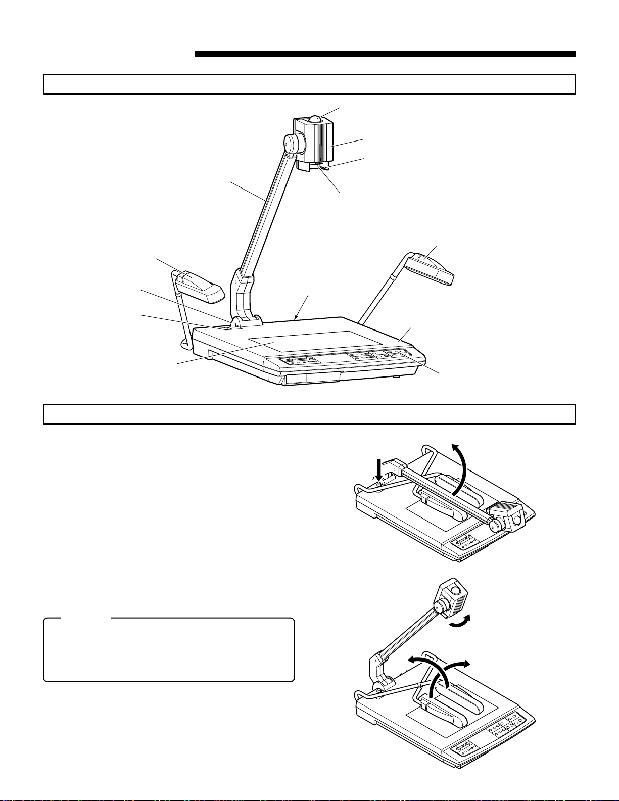
Part names
Side illumination
Remote control light reception section
Camera head
Slide film holder
Camera arm
Close-up lens
Side illumination
Lock release button
(UNLOCK)
POWER switch
Back illumination
Setup
1.
While pressing the UNLOCK button 1, raise the camera
arm so that it stands in the direction shown
2.
When the camera arm is raised all the way, release the
UNLOCK button.
3.
When the UNLOCK button returns to its original position
and the camera arm is locked, release the camera arm.
4.
T urn the camera head in the direction shown 3 until a click
is heard. The camera head should no w be facing the stage.
2
Rear panel
Stage
Control panel
2
.
1
5.
Move the side illumination arms in the directions shown,
and then 5.
first
4
CAUTION
• When using the UNLOCK button, do not release the
camera arm until it is locked. Do not apply excessive force on the side illuminations (arms and lights),
otherwise, a malfunction or injury may result.
4
4
3
5
Page 5
6.
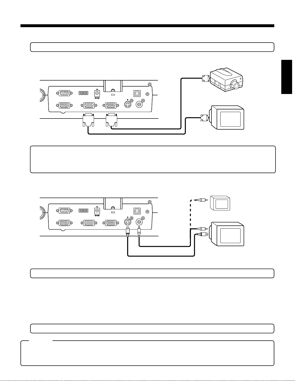
Perform the following connections to the input connector of a projector or display.
• To protect this unit and the connected equipment, be sure to turn the POWER switch to OFF before connecting cables.
● Connection with the equipment with the D-sub 15-pin input connector (for main picture presented using a projector, etc.
Projector
Rear panel
REMOTE INPUT (RS-232C)
EXT INPUT
1
0
ABCDEF
MODE
RGB OUTPUT 1
DC OUTPUT
DC12V 400mA
RGB OUTPUT 2
S-VIDEO
OUTPUT
USB
VIDEO
OUTPUT
Display
Commercially-available D-sub 15-pin cable
• It is recommended that you use the shortest possible cable (less than 3 m) when connecting equipment to the RGB output
terminal.
• Set the RGB output according to the specifications of the projector or display to be connected.
(For setting, refer to the rear panel "MODE" on page 8.)
● Connection with the equipment with the Video or S-Video/ input connector for monitor and preview piduters. D-sub 15-pin input
connector (for main screen)
Rear panel
REMOTE INPUT (RS-232C)
EXT INPUT
ABCDEF
1
0
RGB OUTPUT 1
DC OUTPUT
DC12V 400mA
RGB OUTPUT 2
S-VIDEO
OUTPUT
USB
VIDEO
OUTPUT
LCD monitor
TV monitor
ENGLISH
Provided video cable
Commercially-available S-video cab le
• For The USB cable connection, refer to the separate "Application software instructions".
7.
Connect the connector of the provided power cord into AC IN (refer to page 9) and the connect plug to an AC outlet, then turn the
POWER switch ON.
● To store this unit, perform the set-up procedure (see page 4) in reverse order:
Fold the side illumination arms first. Then press the UNLOCK button to fold the camera arm.
• Facing the unit, start with the right side illumination arm (the
side in the illustration at the bottom of page 4)
5
Keep the camera head parallel to the camera arm.
• Hold the plug when unplugging the power cord or video cables.
CAUTION
• When storing this unit, do not lean it against a wall, etc. If it falls over, a malfunction or injury may result.
• During transportation, do not hold the camera arm, side illumination (lamp or ar m), etc. Doing so could place
excessive force on the unit, resulting in a malfunction or injury.
5
Page 6
OPERATION
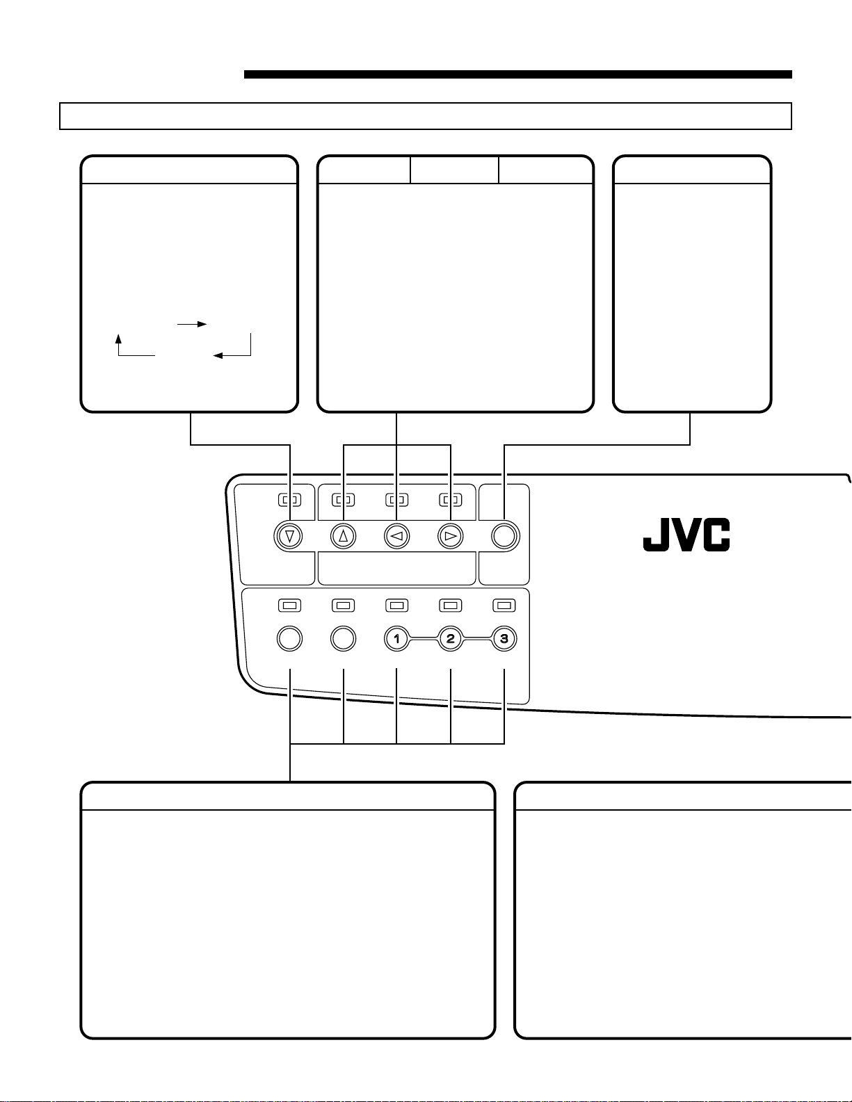
Control panel
LIGHTS
Use to turn on either the side illuminations or the back illumination.
With factory setting, when the
power is switched on, the side illuminations will come on.
Every time the button is pressed,
the lighting of the unit changes as
follows:
Side illuminations
ON
all lighting
OFF
side illuminations ON again, and
so on.
back illumination
ON
LIGHTS
NEGA/POSI BW/COLOR TEXT MODE
NEGA/POSI: Reverse the colors and bright-
ness of a picture.
Reverses negative film images
to enable normal color picture
output.
(In the NEGATIVE mode, settings are for the negative film.)
BW/COLOR: Changes a color picture into
B/W. If used when showing
B/W material, definition of the
picture will improve.
TEXT MODE: Makes characters clearer and
sharper. Use to show text material for effective presentation.
ONBWNEGA
NEGA/
POSI
BW/
COLOR
TEXT
MODE
MENU/
ENTER
DIGIT AL PRESENTER AV-P950
MENU/ENTER
Use to perform camera
adjustments and setting
on the on-screen display.
(Refer to "Menu adjustment" on page 10.)
PICTURE MEMORYEXT INCAMERA
SOURCE SELECT
SOURCE SELECT
Use to select the output picture. Choose from camera, EXT INPUT
connector, or picture memory.
CAMERA: Picture from the camera is selected.
EXT IN: The picture input to the EXT INPUT connector
(from a personal computer, for example) is
selected.
PICTURE MEMORY: When a picture is stored in memory, it can be
(1, 2, 3)
• The picture input from the EXT INPUT connector cannot be used for
the output to the VIDEO OUTPUT and S-VIDEO OUTPUT
connectors. (See the rear panel on pages 8 and 9)
selected as the output picture (refer to "Picture
memory" on page 15).
FOCUS
Use to adjust the focus of the camera picture.
AUTO: When this button is pressed for
automatic focusing of an image, the
indicator starts blinking. As soon as
focusing is achieved the indicator will
go out.
NEAR: Press this button to reduce the focal
length (to focus on a point closer to the
camera).
FAR: Press this button to increase the focal
length (to focus on a point further from
the camera).
• Press the AUTO button to exit the menu
display.
6
Page 7

● You can perform the same operations using a remote control unit (see the Remote control unit section on page 11).
BRIGHTNESS
Use to adjust the brightness of a
camera picture.
AUTO: Press this button to
automatically adjust
the brightness. The
indicator blinks.
When brightness
adjustment is
complete, this
indicator goes out.
DARKER: Press to make the
picture darker.
BRIGHTER
AUTO
: Press to make the
picture brighter.
BRIGHTNESS
BRIGHTERDARKER
AUT O WHITE SET
Use to adjust the white balance of
a camera picture automatically.
Shoot a white paper in full screen,
adjust the brightness and then
press the button. The indicator
blinks and the white balance is set
automatically. When adjustment is
complete, the indicator goes out.
• When lighting in the surroundings changes, adjust the white
balance again.
ZOOM PRESET
AUT O WHITE
SET
ZOOM PRESET
Use to set a camera picture size to
A4 or A5 at the touch of a button.
A4/LETTER: Press to show A4
landscape-oriented
material in full screen
view.
A5: Press to show A5
landscape-oriented
material or the upper
or lower half of A4
portrait-oriented material in full screen
view.
A5A4/LETTER
ENGLISH
FOCUS
AUTO
FARNEAR
䡵Note on focus operation
Under the following conditions, it may not be
possible to obtain proper focus with the
AUTO button. In this case, adjust the focus
with the FAR or NEAR button.
• Object with low contrast
• Shiny object
• Dark screen
• Horizontal stripes
• Lattice pattern
• Moving object
• Object not located at the center of the screen
• 3-dimensional object
OFF
FREEZE
ON
FREEZE
Use to switch the camera or
picture between live action still
images.
OFF: Press to show the camera
picture as a live action image.
ON: Press to show the camera
picture as a still image.
Use this function when
changing material for a
smoother presentation.
ZOOM
INOUT
ZOOM
Use to increase or decrease
the size of an object shot
output by the camera.
OUT:Press to show all of or
most of an object.
IN: Press to enlarge a specif-
ic part of an object.
• When the digital zoom is set
to x2 or x4, the picture may
shake a little while the magnification value is being
changed.
7
Page 8

Rear panel
MODE
ABCDEF
1
• All switches are
factory-set to “1”.
0
Mode setting for the RGB
output picture
AB
XGA (1024 X 768)
SVGA (800 X 600)
VGA (640 X 480)
........
........
........
11
01
00
• When using either SVGA or VGA mode,
the picture quality will be slightly inferior
to that of XGA mode.
REMOTE IN
Use to control the unit from a personal
computer via RS-232C(see page 16).
Use to set the RGB output picture mode or sync signal
mode. Set it according to the specifications of the
connected projector or display.
Preview mode setting 1
(see page 14) 0
Menu display setting 1
....
....
....
....
0
OFF
ON
Display
No display
• If No Display is selected for the MENU Display setting
while the PREVIEW mode setting is ON, this setting will be
applicable only with the RGB output pictures.
Setting of sync signal for 1
G signal from RGB OUTPUT 0
Mode setting for sync 1
signal from RGB OUTPUT 0
....
NO (not added)
....
YES (added)
....
Horizontal sync signal
....
Composite sync signal
EXT INPUT
Input RGB signals such as video signal from a personal
computer, or sync signal.
Use to input RGB signals such as video signals from a
personal computer, and sync signals. Select the picture
to be shown instead of the camera picture using the EXT
IN button of SOURCE SELECT on the control panel.
• Input signals will be transferred directly to RGB
OUTPUT 1 and RGB OUTPUT 2, regardless of the
picture mode settings of RGB OUTPUT on this unit.
• Set the signal of the equipment connected to the
EXT INPUT connector according to the
specifications of the connected projector or display.
REMOTE INPUT (RS-232C)
EXT INPUT
ABCDEF
1
0
MODE
RGB OUTPUT 1 RGB OUTPUT 2
DC OUTPUT
DC12V 400mA
RGB OUTPUT1, RGB OUTPUT2
RGB OUTPUT1, RGB OUTPUT2
Outputs camera pictures or signals from EXT
INPUT.
8
Page 9

DC OUTPUT
USB
Supplies the power exclusively for the
optional LCD monitor (TA-AV-Z7U).
CAUTION
Connect TA-AV-Z7U only. Connecting
other apparatus may cause
malfunctioning.
LCD monitor installation holder
Use to attach the optional LCD monitor (TAAV-Z7U) to this holder. For installation
procedure, refer to the LCD monitor's
instruction manual.
Use to transfer pictures to a personal computer.
Also, use to control this unit from a personal
computer.
* For instructions on installation of picture-transfer
software in your personal computer and data
transfer procedures, refer to the separate
"Application software instructions".
ENGLISH
USB
S-VIDEO
OUTPUT
VIDEO
OUTPUT
S-VIDEO OUTPUT, VIDEO OUTPUT
S-VIDEO OUTPUT
Outputs a camera picture with Y/C signals.
VIDEO OUTPUT
Outputs a camera picture with composite signals.
Outputs the same picture as the one output by SVIDEO OUTPUT.
• Input signals at EXT INPUT connector cannot be
used for the output at these connectors.
AC IN
Plug the connector of the provided power cord into
this inlet.
Use a 220 V to 240 V AC power supply.
CAUTION
• Only use the provided power cord. If a power
cord with insufficient electric current capacity is
used, the cord can overheat and cause a fire.
• Be sure to use a commercial AC220 V-240 V
power supply.
9
Page 10

Menu adjustment
䡵 Operation
The adjustment and setting of this unit can be performed
with the on-screen menu displayed by the projector or
monitor.
Press the MENU/ENTER button
Select the adjustment item with the 䊲 button
3
.
button
Set the data with the 䊴 button
to display the menu.
1
and the 䊱
2
and the 䊳 button 5 .
4
When the setting is complete, press the MENU/ENTER
button to exit the menu display.
23451
ONBWNEGA
TEXT
BW/
NEGA/
LIGHTS
POSI
SOURCE SELECT
COLOR
PICTURE MEMORYEXT INCAMERA
MODE
MENU/
ENTER
䡵 Functions
The functions and settings for each adjustment item are shown below.
Adjustment item Functions and settings Initial value
RED LEVEL 0
BLUE LEVEL 0
DIGITAL ZOOM x 2
Adjusts the red level of the camera picture.
-30 to +30 (in increments of 1 step)
Adjusts the blue level of the camera picture.
-30 to +30 (in increments of 1 step)
Sets the maximum magnification of the digital zoom.
OFF/x2/x4
• The altered setting will become effective only when the ZOOM button is pressed.
JPEG
Sets the compression rate of the JPEG picture captured to a personal computer via
FINE
the USB connector.
FINE : Highest picture quality, but large file size. Normally, use this mode.
NORMAL : The file size is between FINE and ECONOMY.
ECONOMY : Lower picture quality, but smaller file size.
FINE/NORMAL/ECONOMY
LOAD CANCEL
Selects the settings.
DEFAULT : Returns the current conditions to the initial values (factory-set values).
Select DEFAULT and exit the menu to start operation.
USER : Changes the current settings to those stored in memory with the SAVE
function shown below. Select USER and press the MENU/ENTER button
to start operation.
CANCEL/DEFAULT/USER
SAVE CANCEL
Stores current settings in memory.
Select OK and press the MENU/ENTER button to store the settings in memory.
The stored settings will be applied the next time the presenter is powered up.
CANCEL/OK
• When E on the rear panel MODE switch is set to 0, there will be no menu display. (refer to MODE on the rear panel on page 8).
• When the camera picture mode is SVGA or VGA, the definition of the menu display is reduced slightly.
• With the digital zoom magnification set to x4, the picture may be pixelated when the magnification is maximized. It is recom-
mended to normally use x2.
• The settings for SOURCE SELECT and FREEZE cannot be saved. When the pow er is supplied, SOURCE SELECT is set to
CAMERA and FREEZE is set to OFF.
• While the menu is displayed on the screen, settings for TEXT MODE, BW/COLOR, NEGA/POSI and LIGHTS cannot be
altered. To make alteration, first exit the menu display and then change the setting.
10
Page 11

Remote control unit
5
6
7
To use the remote control unit, point it toward the remote
control light receptor (at the top of the camera head).
The effective operating distance is up to 5 meters from the
receptor (with new batteries). The remote control unit requires two standard AA batteries. Open the cover of the
battery case on the rear of the remote control unit and set
the batteries in the correct direction, according to the +
and - marks.
䡵 Functions
Items Functions
FREEZE
OFF
1
PICTURE MEMORY
AUTO
AUTO
AUTO
WHITE
ON
2
BRIGHTNESS
FOCUS
OUT IN
ZOOM
EXT IN
3
SSV3932
4
3
ENGLISH
2
1
UNITCONTROLREMOTE
ZOOM [IN/OUT]
1
FOCUS
2
BRIGHTNESS
3
EXT IN
4
FREEZE [OFF/ON]
5
PICTURE MEMORY 1/2/3
6
AUT O WHITE
7
Use to change the output size of an object to shoot.
Use to adjust the focus of the camera picture.
Use to adjust the brightness of the camera picture.
Use to select and output the picture input to the EXT INPUT connector.
Use to switch the camera picture to a live action image or a still image.
Use to select and output the picture stored in memory.
Use to adjust the white balance of the camera picture.
• You cannot store a picture in memory with the PICTURE MEMORY button on the remote control unit. Use the button on the
main unit.
• The provided batteries (AA) should only be used to check operation. Install new batteries before use.
Notes on the remote control unit
● Light reception range of the remote control unit is within a
horizontal radius of 5 meters from the remote control light
receptor. Use the remote control unit within this range.
● If direct sunlight or powerful illumination (inverted fluorescent
light, flash light, etc.) or infrared light are shone on the remote
control light receptor, the remote control ma y not function properly. In that case, change the position of the unit or the direction of the illumination.
● If there is a person or an object between the remote control and the light receptor, signal reception may not be possible. When the
camera head is rotated to shoot surrounding objects, the light receptor may not receive the signal.
● If the remote control is dropped or a violent shock is applied to it, the internal mechanism and electronic parts may be damaged. Be
careful when handling it.
● When batteries are close to depletion, signal reception weakens. In this case, replace the batteries with new ones.
CAUTION
• When changing the batteries, always replace both batteries with new ones . Do not use a new battery together with
an old one. Otherwise, a fire or injury may result due to the explosion or leakage of the battery.
• When the remote control is not used for a long period (more than one month), remove the batteries. Otherwise , a fire
or injury may result due to the explosion or leakage of the battery.
• Do not charge, disassemble or heat a battery, nor throw it into a fire. Otherwise, a fire or injury may result due to the
explosion or leakage of the battery.
Remote control light receptor
approx. 20° approx. 20°
Horizontal direction of 360°
Vertical direction of approx. 20°
11
Page 12

PRESENTATION (BASIC)
Printed material and 3-dimensional objects
1.
Adjust the position 1 and direction 2 of the side illumination lamps so that the stage receives uniform lighting.
2.
Place an object on the white back illumination area of the
stage.
3.
Adjust the picture size with the ZOOM buttons 3 while
checking the screen.
4.
When the picture size is determined, adjust the focus with
the FOCUS buttons
• It is recommended to turn on the side illumination lamps.
• Set the picture mode for the RGB output according to the
specifications of the connected projector or display (see
page 8).
• It is recommended to use the preview mode when you do
not want to show changes of presentation objects or picture adjustments on the main screen (RGB output) (see
page 14).
1
.
1
2
1
2
5
Slide presentation
1.
Adjust the position 1 and direction 2 of the side illumination lamps so that the stage receives uniform lighting.
2.
Insert the film into the slide film holder in the direction shown
.
6
3.
Adjust the size of the picture with the ZOOM OUT button
.
3
4.
When the picture size is determined, adjust the focus with
the FOCUS buttons
5.
Adjust the screen brightness with the BRIGHTNESS but-
.
tons
5
• Magnifying the slide film (vertical) until the mount section
can no longer be seen makes focusing impossible . Press
the ZOOM OUT button for adjustment.
• Do not place any other materials on the stage because
they will block the reflected light from the side illumination
lamps.
• Use regular plastic slide mounts.
4
.
AUTO
AUTO
BRIGHTNESS
FOCUS
AUTO WHITE
OFF
SET
ON
BRIGHTERDARKER
FARNEAR
ZOOM PRESET
A5A4/LETTER
ZOOM
INOUT
43
6
Mount
12
Slide film holder
Slide film
Page 13

Transparent material such as OHP sheets
1.
Press the LIGHTS button 7 to turn on the back illumination.
2.
Put the transparent material on the stage.
3.
Adjust the screen brightness with the BRIGHTNESS but-
.
tons
5
4.
Adjust the picture size with the ZOOM buttons 3.
7
LIGHTS
NEGA
NEGA/
POSI
BW/
COLOR
ONBW
TEXT
MODE
MENU/
ENTER
ENGLISH
5.
When the picture size is determined, adjust the focus with
the FOCUS buttons
4
.
Capturing images of surrounding objects
To shoot the face of a person or nearby objects, proceed as
follows.
1.
Remove the close-up lens by turning it in the direction shown
.
8
2.
Direct the camera head in the direction shown 9 (towards
the back of the unit).
• To shoot the stage, attach the close-up lens.
• Be careful not to get fingerprints or dust on the close-up
lens. If the lens gets dirty, wipe it with a clean cloth or
commercially-available lens cleaner for camera.
• The camera head will not turn towards you (as you face
the unit). Do not attempt to turn it by force.
PICTURE MEMORYEXT INCAMERA
SOURCE SELECT
8
9
13
Page 14

PRESENTATION (APPLICATION)
Preview mode
By using the preview mode, y ou can adjust z oom and focus on the preview monitor bef ore outputting the picture to the main presentation screen. This makes it possible for you to make a smooth, prof essional presentation because material changes and screen adjustments are not shown. The following example describes how to transfer an image to the main projector.
䡵 Connection and setting
1.
Connect the RGB OUTPUT 1 or RGB OUTPUT 2 connector to the input connector of the projector.
2.
Connect the VIDEO OUTPUT or S-VIDEO OUTPUT connector to the input connector of the preview monitor.
3.
Turn the power on.
4.
Set the DIP switch F on the rear panel to 0 to engage the preview mode.
• For cable connection, refer to page 5.
• It is recommended to use the optional LCD monitor (TA-AV-Z7U) as a preview monitor. For connections, refer to the LCD
monitor's instruction manual.
䡵 Operating procedure
ZOOM PRESET
BRIGHTNESS
AUTO
AUTO
AUTO
AUTO
BRIGHTNESS
BRIGHTERDARKER
BRIGHTERDARKER
FOCUS
FOCUS
FARNEAR
FARNEAR
OFF
OFF
213
AUTO WHITE
AUTO WHITE
SET
SET
ON
ON
1.
Place an object on the stage.
2.
Perform the picture adjustments including the ZOOM but-
tons
and the FOCUS buttons 2 while referring to the
1
preview monitor .
3.
When the adjustments are complete, press the FREEZE-
ON button
4.
The camera picture displayed when the b utton is pressed is
transferred to the projector .
5.
Put the next presentation item on the stage.
6.
Adjust the picture while referring to the preview monitor (even if the main projector is showing a still image or memory picture, the
preview monitor displa ys a motion picture from the camera).
7.
When the adjustments are complete, press the FREEZE-ON button 3.
8.
The camera picture displayed when the b utton is pressed is transferred to the projector .
9.
Repeat steps 5 to 8.
3
.
ZOOM PRESET
ZOOM
ZOOM
A5A4/LETTER
A5A4/LETTER
INOUT
INOUT
14
Page 15

Picture memory
NEGA
NEGA/
POSI
COLOR
BW/
MODE
TEXT
ENTER
MENU/
PICTURE MEMORY
button 1
Up to three of the most frequently used images can be stored in memory for later recall. During a presentation, you can switch between
camera pictures and memory pictures as required. The stored memory pictures are useful for comparing various materials.
䡵 Operating procedure (Storing in PICTURE MEMORY 1)
1.
Shoot the object whose image you want to sav e .
2.
Adjust the picture using the ZOOM buttons 1 and the FOCUS buttons 2.
3.
When the adjustments are complete, press the PICTURE MEMORY 1 b uttons and hold
it for about three seconds.
4.
The indicator starts blinking but once the picture is stored it will remain continuously lit.
5.
When the indicator is continuously lit, release the button. The image is now stored in
memory.
Use the same procedure to store pictures to PICTURE MEMORY 2 and 3.
6.
Press the relevant PICTURE MEMORY button when selecting any of the stored pictures for output.
• Picture memory data is erased when the power is turned off.
• Picture adjustments (ZOOM, FOCUS, BRIGHTNESS, TEXT MODE, NEGA/POSI, BW/COLOR, RED LEVEL, BLUE LEVEL)
cannot be performed for the camera pictures with FREEZE ON or pictures stored in memory. Return them to the FREEZE-OFF
mode first and then adjust again.
• If a digital zoom picture that is stored in the memory is selected, the picture without digital zoom may be momentarily displayed.
LIGHTS
SOURCE SELECT
ONBW
PICTURE MEMORYEXT INCAMERA
5-position camera angle function
ENGLISH
When shooting a 3D object, use the 5-position camera angle
function to add presence and dimensionality to the picture.
䡵 Operating procedure
1.
While moving the camera arm in the direction shown 4,
press the UNLOCK button
2.
Fold the camera arm in the direction shown 6 and when
the required position is obtained, release the UNLOCK
button
3.
Rotate the camera in the direction shown 7 in order to
obtain a desirable angle in relation to the object.
4.
Adjust the picture using the ZOOM buttons 1 and the FOCUS buttons
CAUTION
• Do not release the camera arm when the UNLOCK
button is pressed. Otherwise, a malfunction or injury may result.
to lock the arm (there are 5 lockable positions).
5
.
2
5
.
7
4
6
5
15
Page 16

EXTERNAL CONTROL
1. When using the provided control software
Control panel and menu display/setting functions can be controlled from an external device such as a personal computer.
For connections, software installation and oper ation, refer to the separate "Application software instruction manual".
2. When using customized control software
The functions of this unit can be remote-controlled with an external device via the remote control input connector (RS-232C). If you
wish to create your own customized control software, you can obtain details on communication protocols and commands from your
nearest dealer.
OPTIONAL BOOK HOLDER
When capturing the image of a large object such as an encyclopedia page, it is recommended to use the book holder to
ensure the object remains stable and does not fall. Install the
book holder on the bottom of the unit as described below. Pull
it out for use when required.
1) Use a clean cloth moistened with detergent to wipe off dust,
oil, etc. in the catcher installation grooves (in four places)
on the base of the unit.
2) Remove the backing from the f our catchers and paste them
on the catcher installation grooves
3) Install the book holder in the book holder installation grooves
.
2
1
.
2
Book holder installation grooves
1
Book holder
Catchers
CAUTION
• Do not carry this unit by holding the book holder. If
the book holder comes off and the unit is dropped,
a malfunction or injury may result.
Catcher installation groove
16
Page 17

TROUBLESHOOTING
When you have a problem, check the following points first to see if a solution can be found. If the problem persists, stop using the unit
and consult your JVC dealer.
Symptoms Check these points Page
No picture appears.
Focusing is not possible.
The picture is blurred.
Dust is visible.
The picture is dark.
A stripe pattern appears on
pictures of printed material.
● Is the pow er plug connected to an AC outlet?
● Is the power switch turned on?
● Is this unit connected correctly to the projector or display?
● Is the brightness set to the optimum le vel?
● Are you sure that the pictures have been stored to memory? First store the pictures to
memory and then recall them
● Is EXT IN selected as a source? Select CAMERA.
● Are the picture mode and sync signals set appropriately? Set them according to the speci-
fications of the connected projector or display.
● Is the close-up lens attached?
● Is the object too close to the lens or is the top of the object at a height of more than 100
mm from the stage surface?
● Did you shoot the surrounding objects with a camer a with close-up lens attached? When
shooting surrounding objects, remove the close-up lens.
● Did you enlarge the picture size with the zoom after focusing was achieved? Perform
focusing after enlarging the picture size with zoom.
● With FOCUS A UT O, f ocusing may be difficult depending on the object. In this case , adjust
the focus with the FAR and NEAR buttons.
● If the unit is connected to the projector, make sure that the projector is focused correctly.
Refer to the projector's instruction manual for focusing procedure.
● Is the close-up lens or camera lens dirty? Clean it with a commercially available cleaner.
● Are the side illumination lamps on?
● Is the brightness set appropriately?
●
Dots in the printed matter may interfere with the pixels in the camera image device resulting in
producing color stripes. In this case, change the picture size slightly with the ZOOM buttons.
5
7
15
ENGLISH
6
8
13
7
6
7
The color tone doesn't seem
right.
Beats appear in the picture.
The picture flickers.
The picture cannot be
adjusted.
This unit does not operate even
when the button is pressed.
The remote control does not
work.
The camera picture has
white or black spots.
● Have you adjusted the tone with the AUTO WHITE SET?
● Hav e you set the optimum v alues for RED LEVEL and BLUE LEVEL on the menu display?
● Make sure that the negative mode is not engaged.
● When this unit is used near equipment generating a strong electric wa ve, beats ma y occur
in the picture. Keep this unit away from such equipment.
● In areas where the 50 Hz power frequency is used, flickering may occur on the screen
when a fluorescent light or mercury-vapor lamp is used. Use this unit by lighting the side
illumination lamps.
● When the FREEZE ON, PICTURE MEMORY or EXT IN is selected, the camera picture
cannot be adjusted. Set FREEZE OFF and adjust the picture.
● When brightness is insufficient, this unit may not work properly even if you adjust the
brightness. Press the LIGHTS b utton to light the side illumination lamps.
● When two or more b uttons are pressed at the same time, or a button is repeatedly pressed
without pauses, the unit may not operate correctly . When pressing buttons, do it gently and
slowly.
● Are batteries in the remote control unit?
● Are the batteries exhausted? The provided batteries are for operation check only. Install
commercially available batteries f or actual use .
● Is the remote control unit being operated outside the effective range?
● Black or white spots ma y occasionally appear due to the high-pixel CCD char acteristics of
a moving picture. If the picture is enlarged with the digital zoom function, spots may be
particularly noticeable. It is recommended to use the digital zoom at x2.
7
10
6
11
17
Page 18

SPECIFICATIONS
GENERAL
Power requirements : AC 220 V - 240 V `, 50 Hz/60 Hz
Power consumption : 0.36 A
Dimensions (WHD) : 775 mm x 700 mm x 670 mm (open) (30-9/16" x 27-9/16" x 26-7/16")
(Width: when the lights are moved to the outside maximum)
450 mm x 230 mm x 765 mm (closed) (17-3/4" x 9-1/16" x 30-1/8")
Mass : 9 k˝ ( 19.8 lbs.)
OPTICAL
Lens : F2.9 to F3.1, f = 6.4 mm to 32 mm (5 times)
Shooting area : Max.: 350 mm x 260 mm (13-13/16" x 10-1/4") (B4 size horizontal)
: Min.: 80 mm x 60 mm (2-3/16" x 2-3/8") (with digital zoom OFF)
Focal distance adjustable range
Zoom : Motorized x5 (optical), x4 (digital)
Focus : Auto/manual
Brightness : Auto/manual
LIGHTING
Side illumination : 2 x 6 W (inverter lighting)
Back illumination : 2 x 6 W (inverter lighting, area size is A4 horizontal)
CAMERA HEAD
Output operation mode : Progressive mode, 3-mode switching
Image pickup device : 1/3" CCD
Number of pixels (total) : 850,000 (H1077 x V788)
Frame rate : 15 fps
Synchronization system: Internal
White balance : Auto/manual
Input select : Camera/External input
INPUT/OUTPUT
Input connector : External input (D-sub 15-pin, female) x 1
Output connectors : RGB (D-sub 15-pin, 0.7 V(p-p), 75 Ω, female) x 2
Control connector : Remote input (D-sub 9-pin, RS-232C, male) x 1
ENVIRONMENTAL CONDITIONS
Operating temperature : 5°C to 40°C (41°F to 104°F)
Humidity : 30% to 85%
ACCESSORIES
Provided accessories : Instruction books (this booklet and Application software instructions) x 2, video cable (5 m) x 1, power
OPTIONS
LCD monitor (TA-AV-Z7U)
Book holder
Book holder (JVC Part No. SS22717-001) x 2
Catcher (JVC Part No. SS411744-003) x 4
: From the stage surface to a height of 100 mm (3-15/16") from the stage surface (the camera
directed downward, with close-up lens)
∞ to 0.8 m (2.6 ft) (the camera directed to the side, without close-up lens)
1024 dots x 768 dots H : 48.4 kHz/V: 60.0 Hz
800 dots x 600 dots H : 37.9 kHz/V: 60.3 Hz
640 dots x 480 dots H : 31.5 kHz/V: 59.9 Hz
Interlace mode
PAL H : 15.75 kHz/V:50 Hz
S-video (Mini DIN 4-pin, 1 V (p-p), 75 Ω) x 1
Video (RCA pin, 1 V (p-p), 75 Ω) x 1
USB (series B) x 1
DC 12 V (DC jack) x 1 (Used exclusively with the LCD monitor TA-AV-Z7U)
cord x 1, remote control unit x 1, battery (AA) x 2, floppy disk (application software) x 3
Design and specifications subject to change without notice.
● To save electricity, turn the power off when not in use.
18
Page 19

AV-P950E DIGITAL PRESENTER
R
is a registered Trademark owned by VICTOR COMPANY OF JAPAN, LTD.
R
is a registered Trademark in Japan, the U.S.A., the U.K. and many other countries.
© 2001 VICTOR COMPANY OF JAPAN, LIMITED
R
VICTOR COMPANY OF JAPAN, LIMITED
Printed in Japan
SS961589-001
 Loading...