

Page 1
SERVICE MANUAL
COLOR TELEVISION
C-N21310
C-N21103
AV-N21203
BASIC CHASSIS
C-N21310
C-N21103
AV-N21203
[C-N21310/S]
/S
/S
/S
[C-N21103/S]
[AV- N21203
FV5
/S
]
CONTENTS
!
SPECIFICATIONS ・・・・・・・・・・・・・・・・・・・・・・・・・・・・・・・・
! SAFE TY PRECAUTIONS ・・・・・・・・・・・・・・・・・・・・・・・・・・・・・・・・
!
FEATURES
!
MAIN DIFFERENCE LIST ・・・・・・・・・・・・・・・・・・・・・・・・・・・・・・・・
! SPECIFIC SERVICE ・・・・・・・・・・・・・・・・・・・・・・・・・・・・・・・・
!
SERVICE ADJUSTMENTS
★ STANDAR D CIRCUIT DIAGRAM (APPENDIX) ・・・・・・・・・・・・・・・・・・・・・・・・・・・・・・・・
! PARTS LIST ・・・・・・・・・・・・・・・・・・・・・・・・・・・・・・・・
1
・・・・・・・・・・・・・・・・・・・・・・・・・・・・・・・・
・・・・・・・・・・・・・・・・・・・・・・・・・・・・・・・・・・・・・・・・・・・・・・・・・・・・・・・・・・・・・・・・
・・・・・・・・・・・・・・・・・・・・・・・・・・・・・・・・・・・・・・・・・・・・・・・・・・・・・・・・・・・・・・・・
・・・・・・・・・・・・・・・・・・・・・・・・・・・・・・・・・・・・・・・・・・・・・・・・・・・・・・・・・・・・・
・・・・・・・・・・・・・・・・・・・・・・・・・・・・・・・・・・・・・・・・・・・・・・・・・・・・・・・・・・・・・・・・
・・・・・・・・・・・・・・・・・・・・・・・・・・・・・・・・・・・・・・・・・・・・・・・・・・・・・・・
・・・・・・・・・・・・・・・・・・・・・・・・・・・・・・・・・・・・・・・・・・・・・・・・・・・・・・・・・・・・・・・・
・・・・・・・・・・・・・・・・・・・・・・・・・・・・・・・・・・・
・・・・・・・・・・・・・・・・・・・・・・・・・・・・・・・・・・・・・・・・・・・・・・・・・・・・・・・・・・・・・・・・
・・・・・・・・・・・・・・・・・・・・・・・・・・・・・・・・・・・・・・・・・・・・・・・・・・・・・・・
・・・・・・・・・・・・・・・・・・・・・・・・・・・・・・・・・・・・・・・・・・・・・・・・・・・・・・・・・・・・・・・・
・・・・・・・・・・・・・・・・・・・・・・・・・・・・・・・・・・・・・・・・・・・・・・・・・・・・・・・・・・・
・・・・・・・・・・・・・・・・・・・・・・・・・・・・・・・・・・・・・・・・・・・・・・・・・・・・・・・・・・・・・・・・
・・・・・・・・・・・・・・・・・・・・・・・・・・・・・・・・
・・・・・・・・・・・・・・・・・・・・・・・・・・・・・・・・・・・・・・・・・・・・・・・・・・・・・
・・・・・・・・・・・・・・・・・・・・・・・・・・・・・・・・・・・・・・・・・・・・・・・・・・・・・・・・・・・・・・・・
・・・・・・・・・・・・・・・・・・・・・・・・・・・・・・・・・・・・・
・・・・・・・・・・・・・・・・・・・・・・・・・・・・・・・・・・・・・・・・・・・・・・・・・・・・・・・・・・・・・・・・
・・・・・・・・・・・・・・・・・・・・・・・・・・・・・・・・・・・・・・・・・・・・・・・・・・・・・・・・・・・・・・・・
・・・・・・・・・・・・・・・・・・・・・・・・・・・・・・・・・・・・・・・・・・・・・・・・・・・・・・・・・・・・・・・・
COPYRIGHT © 2002 VICTOR COMPANY OF JAPAN, LTD.
・・・・・・・・・・・・・・・・・・・・・・・・・・・・・ 2
・・・・・・・・・・・・・・・・・・・・・・・・・・・・・・・・・・・・・・・・・・・・・・・・・・・・・・・・・・
・・・・・・・・・・・・・・・・・・・・・・・ 3
・・・・・・・・・・・・・・・・・・・・・・・・・・・・・・・・・・・・・・・・・・・・・・
・・・・・・・・・・・・・・・・・・・・・・・ 5
・・・・・・・・・・・・・・・・・・・・・・・・・・・・・・・・・・・・・・・・・・・・・・
・・・・・・・・・・・・・・・・・・・・・・・・・・・ 6
・・・・・・・・・・・・・・・・・・・・・・・・・・・・・・・・・・・・・・・・・・・・・・・・・・・・・・
・・・・・・・・・・・・・・・・・・・・・
・・・・・・・・・・・・・・・・・・・・・・・・・・・・・・・・・・・・・・・・・・
・・・・・・・・・・・・・・・・・・・・・・・・・・・・・・・・・・・・ 27
・・・・・・・・・・・・・・・・・・・・・・・・・・・・・・・・・・・・・・・・・・・・・・・・・・・・・・・・・・・・・・・・
・・・
・・・・・・
11
・・・・・ 2- 1
・・・・・・・・・・
4
No.519 91
Mar. 2002
Mar. 2002
Page 2
C-N21310
A
)
C-N21103
V-N21203
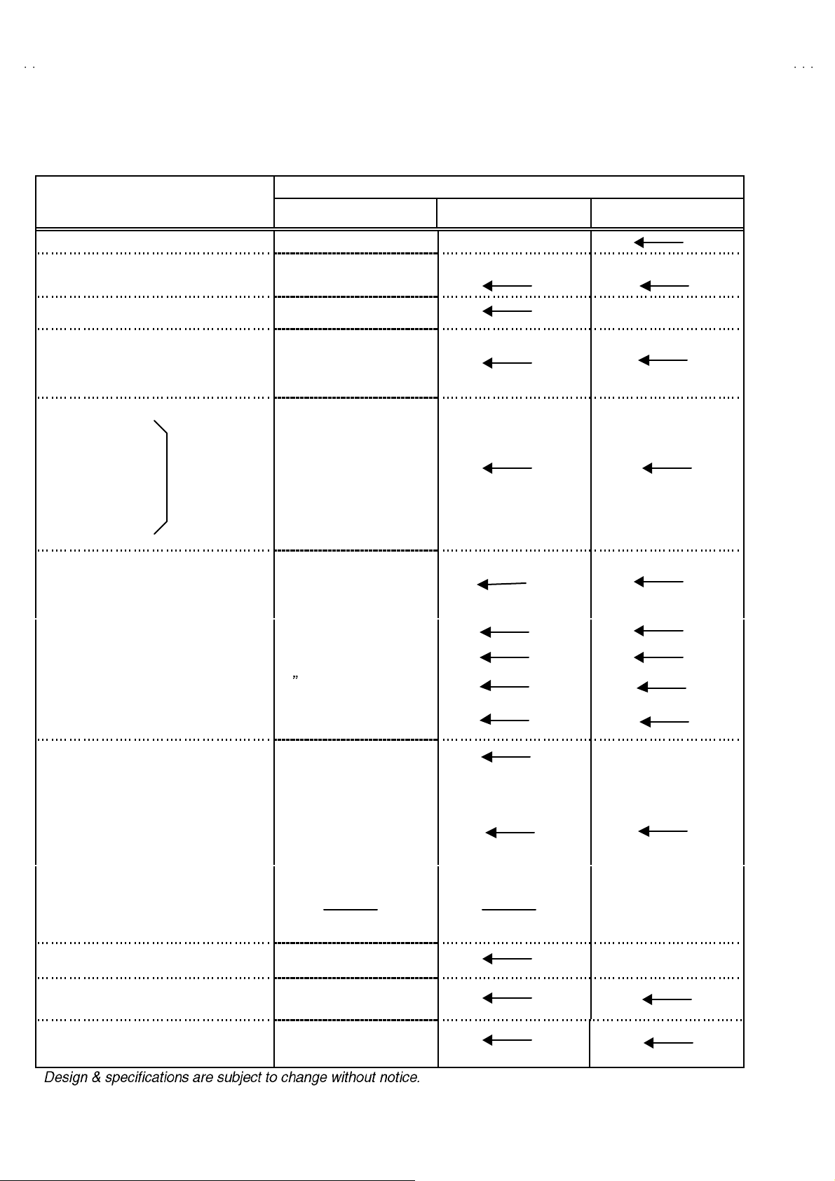
SPECIFICATIONS
Items
Contents
C-N21310/S C- N21103/S AV-N21203/S
Dimensions (W
Mass 19.6 kg 20.2 kg 20.4 kg
TV RF System CCIR(M)
Color Sound System NTSC-M
TV Receiving Channels and Frequency
CATV Receiving Channels and Frequency
TV/CATV Total Channel
Intermediate Fr equency
Color Sub Carrier
Power Input 12 0V AC , 60H z
××××H××××
D) 50 .3cm×45.2cm×49 .3c m 59 .2cm×45.6cm×48 .7c m
VL B a nd
VH B and
UHF Band
Low Band
High Band
Mid Band
Super Band
Hy p er Ban d
Ul tr a B and
Sub Mid Band
Vide o IF Car rier
Sound IF Carrier
(54MHz~80 4MH z)
NT SC-M / BTSC S yst em
(Multi Channel Sound)
(02~06) 54 MHz~88MHz
(07~13) 17 4M H z~ 21 6MH z
(14~69) 47 0M H z~ 80 6MH z
(02~06, A-8) by (02~06 &01)
(07~13) by (07~13)
(A~1) b y (14 ~22)
(J~W) by (23~36)
(W +1~W+ 28) b y (3 7~64 )
(W +29~W + 84) b y (65~1 25)
(A8, A4~A1) by (01, 96~99 )
18 0 Ch an nels
45 .75 MHz
41.25 MHz ( 4 .5MHz)
3.58MHz
Power Consumption 87W
Pictur e Tube
Hi gh Vo l t ag e
Speake r
Audio Powe r Output 1W 1W 1W+1W
Input
Video Input
Au dio Input
Au dio Output 1550mVrms(-4dBs)
Headphone Jack
An ten na Ter mi nal
Remote Control Unit RM-C205
21 (51cm) Measured
Diag onal ly
26 .5kV ±1k V ( at zero b eam
current)
5×9cm
Ova l type×1
1V p- p, 75Ω ( RCA pin jac k)
50 0m Vr ms ( -4dB s ) , Hi gh
Im pe da nce (RCA p in jack )
3.5 mm mi n i j ac k
(Sou nd is mon aural)
75(VHF/UHF) Terminal, F-
Ty pe C on nect or
(AA/R6/UM-3 b atte ry×2)
5×9cm
Ova l type×2
Low impedance (400Hz
when m od ul at ed 10 0%
(RCA pi n ja ck)
3.5 m m st er eo min i jack
(Sou nd is ste re o)
2
No. 51991
Page 3
A
3
SAFETY PRECAUTIONS
C-N21310
C-N21103
V-N2120
1. The d esign of t his p rodu ct c ont ains spec ial h ar dw ar e, man y
ci rcu its and c o mp on ent s s peci al l y for saf ety pur p oses. F or
continued protection, no changes should be made to the
origina l des ign u nless a uth or i zed in wri ting by t he man ufactu re r.
Replacem en t par ts m ust be id ent ic al t o t hos e used in th e
origina l circui t s. S er vic e s ho ul d be perf or me d b y qu ali fied
p ers onnel o nly.
2. Al te rati on s of th e des i g n o r circu itr y of the p rodu cts s hou ld n ot
b e m ad e. A ny de sign alte ra tions or ad di ti o ns will vo id th e
manufacturer's warranty and will further relieve the
manu fac t urer of resp ons ibi lit y f or pe rs ona l i n ju r y or p r ope rt y
d am age r esult ing t heref rom .
3. M an y e lectrical an d mec h an ic al pa rt s in th e produ cts h ave
sp ecial s af ety-r elat ed charact eris tic s. Th ese charac teri sti cs ar e
oft en not e vid en t fr om visu al in spe ction no r can t he prote cti on
aff orde d by th em n ecess ar ily be o bta ined b y usi ng
replac ement compon ent s rated for h ig her vo l tag e, wa ttage, etc.
Replacem en t pa rt s wh ic h h ave t hes e sp ec ial s afet y
ch aracter istics a re i d entifi e d in th e par ts l ist of S ervic e man ua l.
Electrical components having such features are identified
by shading on the schematics and by (!!!!) on the parts list
in S erv ice manual. Th e us e of a su bst itu te re plac emen t whic h
does not have the same saf ety characteristics as the
reco mmen ded replac emen t pa rt sho wn i n the pa rts lis t of
Se rvi c e ma nu al m ay c ause sh ock, f ire, or o th er haz ards.
4. U se isola tio n tr an sf orme r when hot c hass is .
The chassis and any sub-chassis con tained in s ome products
are c onnect ed to on e side of th e AC p ow er l i ne . An i sola ti on
tr ansf or m er of ad equ ate cap acity sh ould be inser t ed bet ween
th e p rodu ct and t he AC p ow er s u pp ly p oi nt while p er for m i ng
an y ser vice on so me pr oducts when th e H OT ch assis is
exp ose d.
5. Don't shor t between the LIVE side ground and I SOLATED
(NE UTRAL) side ground or EARTH side ground when
repairing.
So m e mod el 's p ow er c irc ui t is par t ly dif feren t in the GND. Th e
diff er enc e of t he GN D is s h ow n by th e LI VE : (") side GND,
th e ISO LAT ED(NEU TRAL) : (#) side GND an d EAR T H : ( $)
si de GND. Don 't sho rt be tw ee n t he LIVE s id e GN D a nd
ISO LATE D(N EU TR AL) si de GN D or EART H si de GN D and
never measure with a measuring apparatus (oscilloscope etc.)
th e LI VE s ide GND a nd ISO LATED( N EUTRA L) si d e G ND or
EARTH sid e GND at the s ame time.
If above note will not be kept, a fuse or any parts will be broken.
6. If any re pa ir h as b ee n mad e to th e c h assi s , i t i s re c om m end ed
th at t he B1 se tti n g s h ou ld b e chec ked or ad jus te d (S ee
ADJUSTM ENT OF B 1 POW E R SUPPLY).
7. The hi g h v olt age a pplied t o the pictu re tu be mu st co nform wi th
that specified in Service manual. Excessive high voltage can
cau se an incr ease i n X-R a y emission , arcin g and possi bl e
com po nent d am ag e, th eref or e op er atio n un der ex cess ive hi gh
vol ta ge c ond it i ons sh ou ld be ke pt to a min i mu m, or sh ou ld be
preve nt ed. I f seve re arc ing occu rs, r em ove th e AC p ower
immediately and determine the cause by visual inspection
(incor r ec t i nsta lla ti on , crac ked o r m el te d high vol tag e har ness,
p oor s olde rin g, etc. ). T o ma in ta in the pr op er mi ni m um l e v el of
soft X-Ra y emission, components in the high voltage circuitry
incl ud i ng the pi ctu r e tu be mu s t be the ex a c t r ep lac em en ts or
alte rn at ives a ppr o ved b y th e ma nuf actu r er of th e c o mp l ete
prod uct.
8. Do n ot c hec k high vol ta ge by d r awing a n ar c. U s e a hi gh
vol ta ge m ete r or a hi gh volt age p ro be wi th a VT VM . Disch arge
th e p ictu r e tu be bef ore a tte mp ti ng meter co nne cti on , b y
con nec ting a cl i p lead to th e gr ou nd frame a nd con n ec ti ng t he
oth er e nd of t he lead th roug h a 10 kΩ 2W resist or to t he ano de
bu tto n.
9. W hen s e rvice is r equ i r ed, ob s er ve th e orig inal l ea d dress .
Extra p r ecau ti on s h ou ld be giv en to assu r e cor re ct lea d dr es s
in the hi gh volta ge c ir cu it ar ea . W her e a sh ort ci r cuit ha s
occu rr e d, th ose c ompon en ts th at i nd ic ate ev i den c e of
overheating should be replaced. Always use the
manu fac t urer 's r epl ace m ent com p onents.
10 . Isolation Check
(Safety for Electrical Shock Hazard)
Af ter r e- a s sembling th e pr od uct , always pe rf or m an is o l ation
ch eck on th e expo sed m eta l p ar ts of th e c abi n et ( ant en na
ter m i na ls, vide o/a udio input and out put t er mi n al s, C on trol
knobs, metal cabinet, screwheads, earphone jack, control
sh afts, etc.) to be s ur e th e pr o duc t is saf e t o op er at e wi th out
d ang er of elect ri ca l shoc k.
(1) Di electric Strength Test
The is olat ion b etwe en the AC primary c ircu it and al l m eta l parts
exp osed t o the us er, par t icu l ar l y an y ex po sed metal p ar t h aving
a re tur n pat h to the ch as sis sh ou ld w i ths t and a volta ge of
11 00V AC ( r .m .s.) f or a p eri od of on e sec ond.
(. . . . Withstand a volta ge of 1100 V A C (r.m.s.) to an applian ce
rate d up to 1 20V , and 3 000V AC ( r .m. s.) t o an appl i anc e ra ted
200V or more, for a period of one second.)
Thi s m eth od of test r e qu ires a t es t eq uip ment n ot g en er ally
fou nd in t he servi c e t ra de.
(2) Leakage Current Check
Plug t he A C line cord direct ly i nt o th e AC ou tlet ( do not u s e a
line is olation transf ormer during t his che ck.) . Using a " L eakage
Current Test er", m ea s ur e t he leakag e cur r en t fr om each
exp ose d m eta l par t of th e c a bi ne t, p ar tic ul ar l y an y expo sed
metal part having a retu rn path to t he ch assis, to a kn own good
ea rt h gr o und ( water p ipe, etc.) . A ny l ea k ag e c ur r en t must not
exce ed 0.5m A AC ( r .m. s.) .
Howev e r, in t ro pical a rea, this m ust no t e xc eed 0 .2m A AC
(r.m.s.).
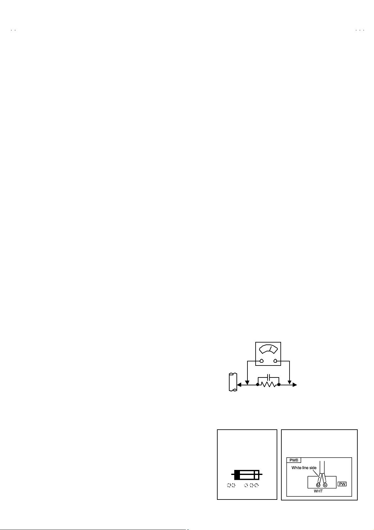
"""" Alte rn at e Che ck M et hod
Plug t he A C line cord direct ly i nt o th e AC ou tlet ( do not u s e a
line isolation transformer during this check.). Use an AC
vol tm et er h av i ng 100 0 ohm s per vol t or m ore s en s iti vity in the
follo win g ma nne r. Connec t a 1 50 0Ω 1 0W resi s tor pa ralle l ed
by a 0.15μ F AC - typ e cap acitor b etwe en an ex p ose d m eta l
p art and a k no wn go od earth gr ou nd (wate r pi p e, et c .).
Measu re th e A C vo ltag e acr os s th e r esist or wit h t he AC
voltmeter. Move the res istor connection to each exposed metal
part, particularly any exposed metal part having a return path to
th e ch assis , an d m ea sur e t he A C volta ge acr oss th e r esisto r.
Now, reve rs e the plu g i n t he A C out let a nd r ep e at e ach
measu rem ent. An y volta ge measu red m us t not exce ed 0.7 5V
AC (r.m. s.) . This corresponds t o 0 .5 mA AC ( r.m.s.).
Howev e r, in tr op ic al ar ea, this m ust n ot excee d 0.3V AC
(r.m.s.). This corr esp on ds t o 0 .2mA A C (r.m.s.).
AC VOLTMETER
(HAVING 1000 Ω/V,
GOOD
EARTH
GR OUND
11 . High voltage hold down circuit check.
Af ter rep ai r of th e high vol t age h ol d d own c i r cuit, th is ci rcu it
sh all be c hec ked to op er ate cor rectly.
See item "How to check the high voltage hold down
cir cuit".
This mark shows a fast
operating fuse, the
letters indicated below
show the r ati ng.
0.15μF AC-T YPE
1500Ω 10W
OR MOR E SENSIT IVITY)
PLACE THIS PROBE
ON E A C H EX PO SE D
ME T AL PA RT
POWE R CORD
REPLACEMENT WARNING.
Co nne c t ing t he w hite l ine s ide of pow er
cord t o “WHT” character side .
A V
No. 51991
3
Page 4
C-N21310
A
(
)
p
C-N21103
V-N21203
FEATURES
" N ew chas sis d esign enab les us e of a s ingle board wit h simpl i fi ed
circuit ry.
"
Provid ed w ith miniatu re tuner (TV/CATV ).
" Mult if unct ion al rem ote c on trol perm i ts pi ctu re a dj ustm ent.
" Ad option of the CHANNEL GUAR D fun cti on prevent s th e s pecifi c
chan nels from being selected, unl ess th e “ ID nu mbe r” is k ey in.
"
I2C bus control utilizes single chip ICs.
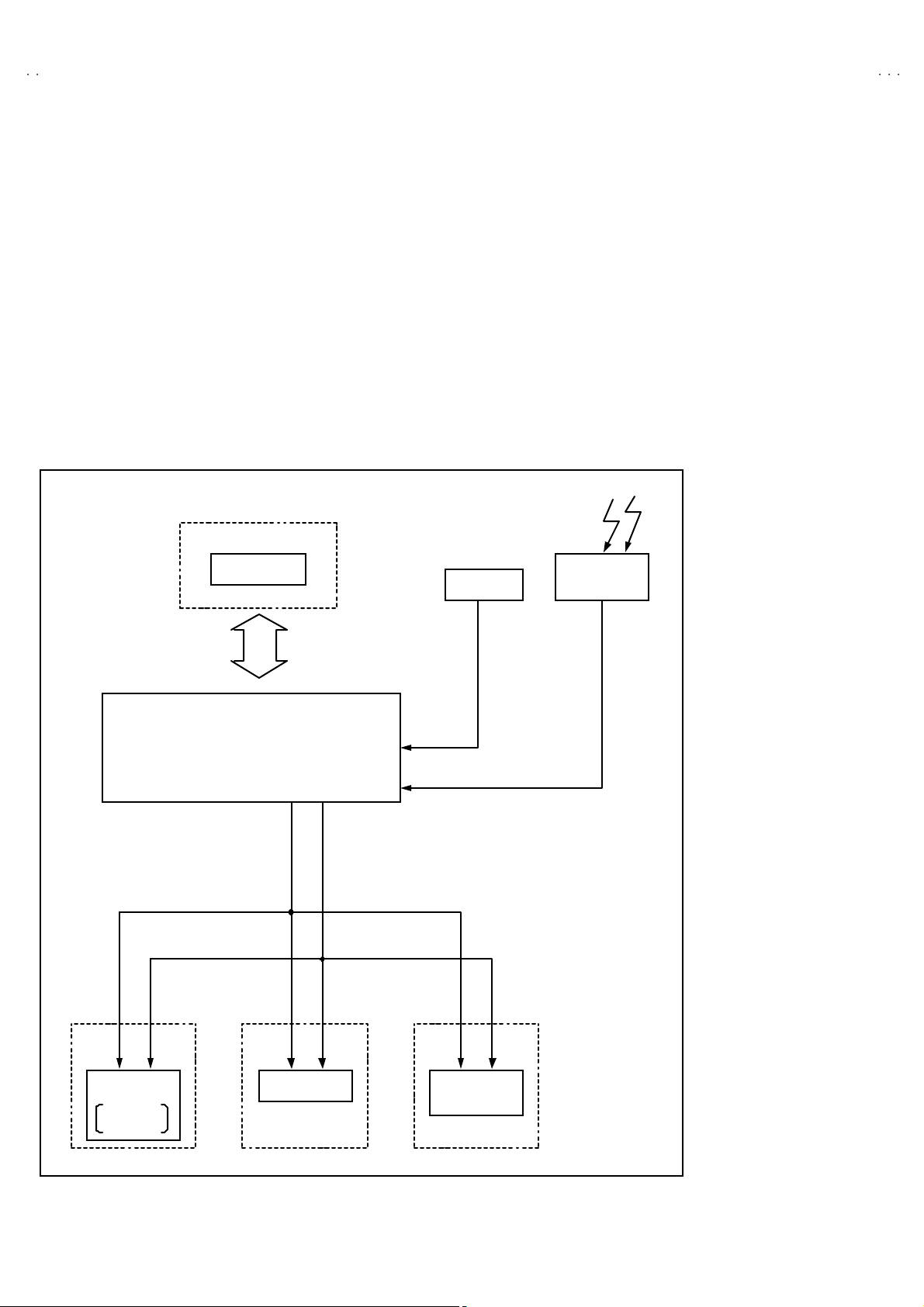
" SYSTEM BLOCK DIAGRAM
MEMORY IC
SCL
SDA
" Ad opti on of the VID EO ST AT US f unc tion .
"
Adoption of the ON/OFF TIMER function.
"
With 7 5ΩV/U in c ommon ( F-Type) AN T Ter minal.
"
SLEEP TIMER for s etting in re al t ime.
" Clos ed- capti on b roa dc asts can be view ed.
" Au di o Vi deo i np ut te rm in al.
"
Au di o outp ut te rminal.(On ly f or AV-N2120 3)
"
Built- in MTS sys tem.(On ly for AV-N21203)
REMOTE
IF1
CONTROL
TUNER
TU NER
CONTRO L
CPU
MAIN M ICON
SCL SDA
TONE
AFC
1Chi
DECO DER
4
No.51991
Page 5
A
MAIN DIFFERENCE LIST
Model
!!!!
Parts Name
MAIN PW B SFV-108 0A- M2 SFV-108 1A- M2 SFV- 108 5A-M2
!
FRO NT CA BIN ET LC10109- 02 1A- A GQ1 0020-004A -A GG1 0020-002B -A
!
POW E R KNOB LC30 376- 00 4A- A GQ3 002 6-002A -A
!
PUSH KN OB
(CO NTROL KNOB)
!
REAR COVE R LC10 108-00 2E- A GQ1 001 3-003B -A GQ1 001 3-002B -A
C-N21310/S AV-N21103/S AV-N21203/S
LC30271- 00 4A- A GQ3 0025-002A -A
C-N21310
C-N21103
V-N21203
Dimensions (W×H×D)
Mass 19. 6 k g 20. 2 k g 20. 4 k g
Color / Sound S yst em
Aud io Power O utpu t 1W 1W 1W+1W
Audio Output
Spea ker
Headphone jack
50. 3cm×45 .2c m×49 .3cm 59. 2cm×45 .6cm×48 .7cm
NTSC-M
5×9cm
Oval type×1
3.5 mm mini jac k
(Soun d i s monaural)
NT SC-M / B TSC System
(Mul ti Chann el Sound)
15 50m Vr ms(-4dBs)
Low imp edance (400Hz
when modu late d 10 0%)
(RCA pi n jack )
5×9cm
Oval type×2
3.5 mm ster eo mini jac k
(Soun d i s stereo)
No.51991
5
Page 6

C-N21310
A
C-N21103
V-N21203
SPECIFIC SERVICE INSTRUCTIONS
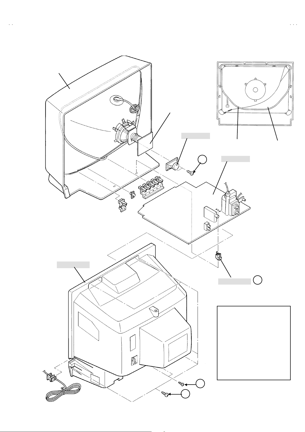
DISASSEMBLY PROCEDURE
REMOVING THE REAR COVER
1. Unp lu g t he po we r s upply cord .
[For C-N21310/S]
2. R em ove th e 5 scr e ws marked !
shown in Fig.1.
[For C-N21103/S ]
2. R em ove th e 9 scr e ws marked !
shown in Fig.1.
[For AV-N21203/S]
2. R em ov e the 9 scr ew s mar ked !
shown in Fig.1.
3. W i thdr a w t he REAR CO VE R t o wa rd you .
[CAUTION]
"
W hen reins t all in g the r e ar cove r, c arefu ll y pus h it i nw ar d af ter
inser ti n g the MA IN PWB i nt o the r ear c ove r gr oo ve .
!an d a scr ew ma rke d """"as
!!
!an d a scr ew ma rke d """"as
!!
!an d 2 s crews m ar ked """"as
!!
REMOVING THE MAIN PW BOARD
" After removing the rear cover.
1. Pic k t hi s side of t he MAIN PW B and rais e on e sligh tl y, tak e off
th e PW B s top per ma rke d #
2. Pu ll out the MAIN PW B as it is.
(If necessary, take off the wire clamp and connectors, etc.)
# from th e ca binet b ott om.
##
REMOVING THE SPEAKER
" Af ter r em oving th e MAI N PW boar d.
1. Rem ove the 2 scr ew s m ar ked
[For C-N21310/S and C-N21103/S]
SP EAKE R ( ×1)
[For AV-N21203/S]
SP EAKE R (×2)
$$$$
.
CHECKIN G THE MAIN PW BOARD
1. To ch eck the ba ck s ide of the MAIN PW Boa rd.
1) Pu ll out the MAIN PW B. ( R ef er to REM OVI NG T HE M AIN
PWB ) .
2) Erec t th e chass is verti ca lly so th at you ca n eas ily check the
backside of the MAIN PW Board.
[CAUTION]
"
When er ect in g t he M AIN PW B, be car ef ul so tha t th er e will be n o
con tact in g with ot her P W Board .
"
Befor e turning on p ower, make su re t hat the CRT e arth wir e and
oth er c o nn ecto rs are p rop er ly c onn ect ed.
WIRE CLAMPIN G AND CABLE T Y ING
1. Be sure c lamp th e wir e.
2. Never rem o ve th e cable ti e used f or tyi ng the w i re s to gethe r.
Sh oul d it be i n adv e rt ent l y rem ove d, be su r e to tie the wires with
a n ew c able tie.
6
No. 51991
Page 7
A
3
FRONT CABINET
CRT SOCKET PWB
(Within MAIN PWB)
SPE AKE R
BRAIDED ASS’Y
C-N21310
C-N21103
V-N2120
DEG. COIL
REAR COVER
D
MAIN PWB
PWB STOP PER
C
Thi s expl od ed view des crib es
ab out the C- N213 10 /S.
Alth ou gh th e C-N21 10 3/S a nd
AV -N 21 20 3/S is sl ig ht ly dif fer en t
fr om thi s f ig ur e, you can u se t his
figu re for d isasse mblin g th e C-
N21103 /S an d A V-N21 203 /S in
the same steps.
B
A
Fig.1
No. 51991
7
Page 8
C-N21310
A
C
S
[
]
C-N21103
V-N21203
MEMORY IC REPLACEMENT
1. Memory IC
This TV uses a memory I C.
Thi s m em or y IC st ores d ata f or pr oper o pera tion of the vide o and deflec ti o n cir cuits.
When replacing t he memory IC, b e su r e t o use an I C writte n with th e in itia l va lues of data.
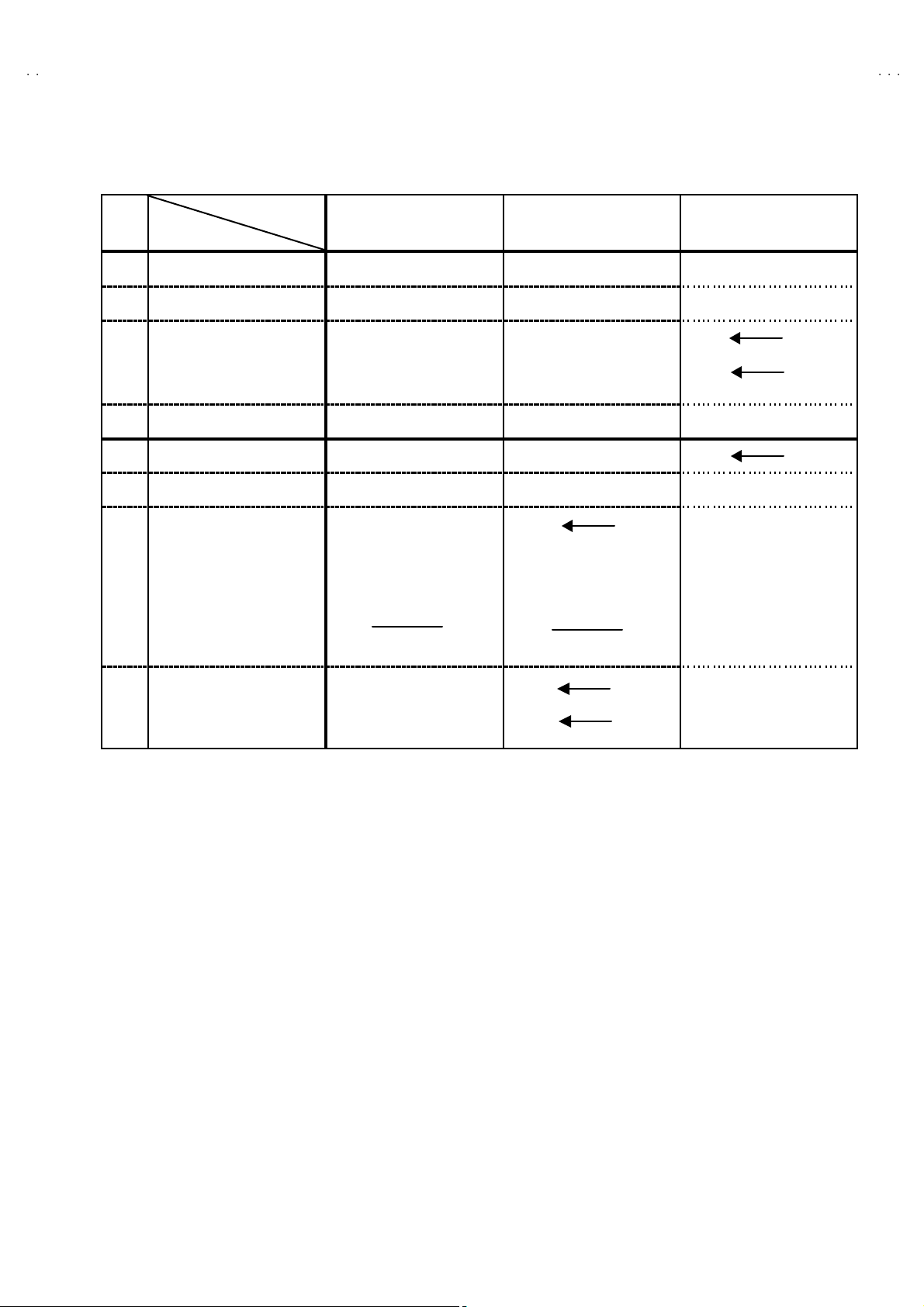
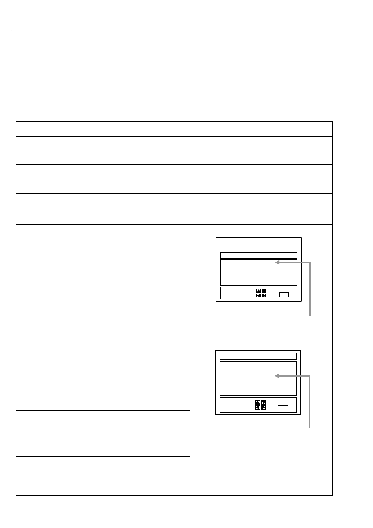
2. Memory IC replacement procedure
Procedure Screen display
(1) Power off
Switch off th e pow er an d di s con nec t th e p ow er c o rd fro m t he out let.
(2) Replace the memory IC
Be sure t o use a memory I C written with the initial settin g data.
(3) Power on
Con nect th e power cord to th e o utlet and switch on the power.
(4) System constant check and setting
" The adjustment should not be done without signal
1) Pr ess SLE EP TIMER key and, while the indication of “SLE EP 0 MIN.”
is being displayed, press DISPLA Y key and VIDEO STA TUS key on
th e r em ot e c ontro l u nit simu lt aneous ly .
2) The SERV ICE M ENU sc r ee n of Fi g.1 is d isp l ayed .
3) W hi l e th e SER VI CE M EN U is d is pl aye d, again simu ltan eou sly p ress
th e DISP LA Y and VIDEO STA TUS ke y s to di s play th e Fig.2 SYSTE M
CONSTANT screen.
4) Refe r to t he SYSTEM CONSTANT t abl e 1 and c hec k th e setti ng item s.
Wher e th ese di ffe r, s el ec t t he s etti n g i tem wit h th e M EN U UP /DOW N
key and adjust the s ettin g with th e MENU L EFT /RIGHT keys. ( Th e
letters of the selec ted item are displayed in yellow.)
5) Af ter ad justing, r el e ase t he ME NU L EF T /R IGHT k ey t o st ore th e set ti ng
value.
6) Press the EX IT key t wice to r eturn th e n ormal scr een.
(5) Rec eiv e channel setting
Refer to t he OPERATING INSTRUCTIONS(USER'S GUIDE) and s et the
receive channels (Channels Preset) as described.
(6) User settin gs
Check th e us er s ett ing it ems ac c ordi ng to Tabl e 2.
Wher e thes e d o not agree, r ef er to th e OP ERATIN G I NSTRUC TION S
(USER'S GU IDE) an d s et t he it ems as des crib ed.
SERVICE MENU
PIC TURE SOUN D
GAME
LOW LIGHT HIGH LIGHT
RF AF C CHK
VCO(CW)
SELECT BY EXIT BY
OPERATE B Y EXIT
Fig.1
SYST EM CO NST ANT
MODEL : *******
HI P : YE
VCAN V-CHIP : YES
********
********-*****
****************
SELECT BY EXIT BY
OPERATE B Y EXIT
*****
**********
*******
**************
Fig.2
Only for AV -N21 20 3/S
Indicated Model Na me
(7) SERVICE MENU setting
Ve rif y what to s et i n th e SER VI CE M EN U , and s et what ever is
necessary.(F ig.1 ) Refer to t he SERV ICE ADJUSTM ENT f or settin g.
8
No. 51991
Page 9

A
3
TABLE 1 (System Constant setting)
Setting value
Setting items Setting contents
C-N21310/S
C-N21103/S
MO DE L Disp l ay th e each a pp licat ion mo del Conf orm abl e m od el n am e
C-N21310
C-N21103
V-N2120
AV-N21203/S
V-CHI P YE S YE S
CAN V-CHIP YE S YE S
YE S NO
YE S NO
TABLE 2 (User setting value)
Setting items Setting value
1. Us e rem ot e c ontr oller keys
POWE R
CHANNEL
CHANNEL PRESET
VOL UME
INPUT (TV/V IDEO)
DISPLA Y
SLEEP TIMER
VIDEO STATU S
2. Set ting of M EN U
TINT
COLOR
PICTURE
BRIGHT
DETAIL
BA SS
TR EBL E
BALANCE
MTS
TV S PEAKER
NOISE M UT ING
SE T VIDEO STATU S
SE T CLOC K
ON/OFF TIMER
LA NG UA G E
CLOS ED CAPTIO N
BACKGROUND
AUTO TUNER SETUP
CHANNEL SUMMARY
V-CHI P
SET LOCK CODE
OFF
CH 02
See O PER ATING I NSTR UCT IO NS .
10
TV
OFF
0
STANDARD
CENTER
CENTER
CENTER
CENTER
CENTER
CENTER
CENTER
CENTER
STEREO
ON
ON
ALL CENTER
Unnecessary to set
NO
SP ANISH
OFF
BLACK
TUNER MODE : AIR
Unnecessary to set
OFF
(0000) : Unnecessary to set
[Only for A V -N21 20 3/S ]
No. 51991
9
Page 10

C-N21310
A
C-N21103
V-N21203
REPLACEMENT OF CHIP COMPONENT
! CAUTIONS
1. Avoid heating for more than 3 seconds.
2. D o n ot ru b t he el ect ro des an d the r esist p arts of the p att ern.
3. W hen rem oving a c hip part, mel t th e s older adequ ately .
4. D o n ot r euse a ch ip p ar t afte r re mo ving it .
! SOLDERING IRON
1. U se a hig h i ns ulatio n s ol der i ng i r on wi th a thi n poin ted e nd of it.
2. A 3 0w s older i ng i r on is rec omm end ed for easil y r em oving p ar ts.
! REPLACEMENT STEPS
1. How to remove Chip parts
#
Resi stors, ca pacitors , etc .
(1) As s h ow n in t he fi gu re, p us h th e p ar t wi th tw eez er s an d
alte rn at ely melt the s ol de r at eac h end.
2. How to install Chip parts
#
Resi stors, ca pacitors , etc .
(1) Apply solder to th e patt ern a s i ndicated in the fi g ure.
(2) Sh if t wi th tw eeze rs and r emo ve th e c h i p p art.
#
Trans isto rs, d io des , va ria bl e r esist or s, etc.
(1) Ap pl y e xt ra so ld er to eac h le ad .
SOLDE R
(2) As s h ow n in t he fi gu re, p us h th e p ar t wi th tw eez er s an d
alte rn at ely melt th e s olde r at eac h l e ad. Shift a nd r em ove th e
chip part.
SOLDE R
(2) Grasp the ch ip p art w i th twe ezers a nd p la ce it on the s older .
The n hea t and me lt th e so lder a t both ends of t he chi p part.
# Transist o rs, dio d es , va ria bl e r esist or s, etc.
(1) Ap ply sold er to the pattern as indic ate d in the figure.
(2) Grasp the ch ip p art wit h t we ezers and p lace it on th e solder.
(3) First s older lead A as indica ted in t he figure.
A
B
C
(4) T he n solder le ads B and C.
A
B
C
Note : A fte r rem oving th e part, re move remain ing solder from th e
pattern.
10
No. 51991
Page 11

A
3
SERVICE ADJUSTMENTS
)
)
ADJUSTMENT PREPARATION:
1. You c an ma ke the nec es sary adjustme nts for t his unit wi th
eit her the R emot e Co ntrol Unit or W ith the adjust m e n t
tool s and parts as given below.
2. Adjustment with the Re mote Control Unit is ma de on t he
bas is of t h e initial sett in g v al ues, howev er, t he ne w s etti ng
values which set the screen to its optimum condition may
differ f rom the init ia l s ettings.
3. M ake sure t hat AC p ower is tu r ned on c orrec tly.
4. T ur n on t he powe r for set and test equ ipm ent bef ore us e, an d
start th e adjus tme nt p r oced ur es aft er waitin g at l east 30
min ute s.
5. Unless oth er w is e spec if ied, pr epar e th e most s ui tab le rece ptio n
or inp ut sign al for adjust ment.
6. N ever t ouch an y ad ju stm en t p ar ts which a re n ot sp ecified i n th e
list for t hi s adjus tm ent - va r i abl e r es istors, tr a ns fo rmer s ,
condensers, etc.
7. Pr esetti ng before ad j ustm en t.
Unless oth erw is e spec if i ed i n th e adjustmen t i ns tr uc t ions,
pres et t he f ollowing function s wi th the rem ote co ntr ol u nit:
User mode position
MENU ITEMS PRESET VALUE
VIDEO STATU S STA NDARD
TINT / COLOUR
PICTURE / BRIGH T
DETAIL
CENTER
C-N21310
C-N21103
V-N2120
ADJUSTMENT EQUIPMENT
1. DC voltmeter (or digital voltmeter)
2. Oscilloscope
3. Si gn al g ener at or (P attern g en erat or) [NTSC]
4. Remote control unit
5. TV a ud io multi ple x si gn al ge ne rator .
6. Frequ enc y c ou nte r
ADJUSTMENT ITEMS
Ad just ment it ems Ad just ment item s
"
B1 POW E R SUPPL Y
" VIDEO / DEF. CIRCUIT Low Light
IF V CO
" WHITE BA LAN CE
Hig h Light MTS STEREO VC O
BA SS / TREBLE
BALANCE
MTS ST ERE O (Only for AV-N21203/S
Adjustment item s
(Only for A V -N21 20 3/S )
"
MTS CIRCUIT
MTS IN PUT L EVEL check
CENTER (Only for AV-N21203/S
RF. AGC
FOCUS SUB BRIGHT MTS FILTER check
V. SIZE SUB C ON TRAS T MTS SE PARATIO N
H. PO SIT IO N MTS COLOR
"
PICTURE MTS SA P VCO
SUB T I NT
No. 51991
11
Page 12

C-N21310
A
(
)
)
C-N21103
V-N21203
ADJUSTMENT LOCATIONS
FRO NT
TP-91
(B1)
R926
POWER
PW
DEG.
F902
F901
ON
TIME R
REM OCON
RECEIVER
TP-12B
CW
31
MP X
IC701
T131 CW
IC201
MENUCH-CH+VOL-VOL+
T
IC702
TUNER
AV-N21203/ S
STEREO
C-N21310/S
C-N21103/S
S
MAIN PWB
IC421
U
HV
HVT
TP-E
( )
IC921
CRT SOCKET PWB
Within MAIN PWB ASS'Y
TP-R
T
TP-E
(SOLDER S IDE
CR T EAR TH
(BRAIDED ASS' Y)
UPPE R : FOCUS
LOWER : SCREEN
U
E1
12
No. 51991
Page 13

A
3
BASIC OPERATION SERVICE MENU
1. TOOL OF SERVICE MENU OPERATION
Operate the SERVICE MENU with the REMOTE CONTROL UNIT.
2. SE RVICE M ENU ITEM S
In ge nera l, basic s ett ing( ad justmen ts ) i tem s o r v er if i cation s ar e pe rf orme d i n the S ERVICE MENU.
"
PICTURE ・・・・・・・・・・・・・・・・・・・・ Thi s se ts th e setti ng values ( adj ust me nt values ) of t he VIDEO /CHROM A and D EF L EC T ION ci rcu its.
" SOUND ・・・・・・・ ・・・・・・・・・・・・・ ・ This s e ts th e s etting va lues ( adj ust me nt values ) of t he AUD IO ci r cuit. [Only for AV-N21203/S]
"
GAME ・・・・・・・ ・・・・・・・・・・・・・ ・・・ This i s us ed w hen the GAM E MO DE is a djust ed.
" LOW LIGHT ・・・・・・・ ・・・・・・・・・・・ T hi s se ts th e s etti ng values ( a djust me nt val ues ) of t he W HIT E BALANC E ci r cuit.
"
HIGH LI GHT ・・・・・・・ ・・・・・・・・・・ T hi s se ts th e setti ng values ( a djust me nt values ) of t he W HIT E BALANCE ci r cuit.
" RF AFC CHK・・・・・・・ ・・・・・・・・・・ This i s us ed w hen the I F VC O i s a dj ust ed. [Do not adjust]
"
VCO (CW ) ・・・・・・・ ・・・・・・・・・・・・ T hi s is us ed when th e IF VC O is a djust ed.
3. Basi c Op era tions of th e SERVI CE M EN U
(1) Ho w to enter the SERVICE MENU.
Press SLE EP TIMER ke y a nd, wh ile th e in di cat i on of “SLE EP 0 MIN.” is being displayed, press DISPLAY key and VIDE O ST ATUS key
on t he re mo te con tr ol un it simultan eo usly t o ente r t he SE RV ICE M EN U sc r ee n .
(2) SE RVICE MENU screen selecti on
Press the UP / DOWN key of the MENU to select any of the following items.
(The l e tte rs of the s elect ed it ems are di sp layed in ye llo w. )
C-N21310
C-N21103
V-N2120
(3) Enter the any setting ( adjustment ) mode
" PICTURE and SOUND mode
1) If select any of PICTURE or SOUND items, and the LEFT / RIGHT key is pressed from SERVICE MENU ( MAIN MENU ), the screen
② will be dis played as shown in figure page later.
2) The n the UP / D OW N k ey is pr ess ed, t he PICTU R E m ode scr een ③ or t he SOUND mo de sc re en ④ i s disp layed , a nd the P IC T U RE
or SOUND setting can be performed.
" GAME, LOW LIGHT, HIGH LIGHT, RF AFC CHK and VCO (CW) mode
1) If select any of GA ME / LOW LIG HT / HIGH LIGHT / RF AFC CHK / VCO ( CW ) items, and t he LEFT / RIGHT ke y is presse d from
SERVICE MENU ( MAIN M ENU ), th e scr eens ⑤ ⑥ ⑦ ⑧ ⑨ will be dis played as shown in figure page later.
2) The n the sett in gs or verifi cation s ca n be p erfor med .
[Only for A V -N21 20 3/S ]
No. 51991
13
Page 14

C-N21310
A
C-N21103
V-N21203
SERV IC E MENU (MAI N ME NU)
①①①①
SE RV IC E M EN U
PICTURE
GAME
LOW L IGH T HIGH LI GHT
RF AFC CHK
VC O (CW )
SE LEC T BY
OPERATE BY
SOUND
EX IT BY
[Onl y for AV-N212 03/S]
HIGHLIGHT MODE
⑦⑦⑦⑦
HIGH LIGHT
** *
** *
** *** *
EX IT BY
RF AFC CHK M ODE [DO NOT AD JUST ]
⑧⑧⑧⑧
EXIT
** *
** *
** *** *
EXIT
SCREEN
②②②②
IT
SE LEC T BY
④④④④
SOU ND MO DE
EX IT BY
EXIT
IT
SE LEC T BY
OPERATE BY
1. BR IGHT
STATUS
PICTURE MODE
③③③③
** *
** *
** *** *
** *** ***
** *** ***
** *** ***** *** ***
EX IT BY
EXIT
IT
[Onl y for AV-N212 03/S]
** *
1 . IN L E VE L
STATUS
IT
SE LEC T BY
OPERATE BY
** *
** *** *
** *** ***
** *** ***
** *** ***** *** ***
EX IT BY
EXIT
IT
RF AFC
FINE
STATUS
SE LEC T BY
OPERATE BY
VCO (CW) MODE
⑨⑨⑨⑨
TOO HIGH
ABOVE REFERENCE
BELOW REFERENCE
TOO LOW
SY N C : YE S
** *
** *
** *** *
** *** ***
** *** ***
** *** ***** *** ***
EX IT BY
EXIT
EX IT BY
EXIT
ON
IT
GAME MODE
⑤⑤⑤⑤
** *
** *
TINT
COLOR
PICTURE
BRIGHT
DETAIL
IT
SE LEC T BY
OPERATE BY
BR IG H T
BRIGHT
** *** *
** *
** *
** *** *
** *
** *
** *** *
** *
** *
** *** *
** *
** *
** *** *
LOW LIGHT MODE
⑥⑥⑥⑥
** * ** * ***
** * ** * ***
** * ** * ***** * ** * ***
** *
** *
** *** *
EX IT BY
EXIT
EX IT BY
EXIT
IT
IT
14
No. 51991
Page 15

A
3
(4) Setting method
1) UP / DOW N key of the MENU
Se lect the SETTING ITEM .
2) LE FT / RIGH T key of the MENU
Setting ( adjus t) t he INITIA L SETTING VA LUE of th e SETT ING ITEM.
W hen th e key is r el ea s ed th e S ETT IN G V ALU E will b e s tor e d
(memorized).
3) EX IT key
Retu rn s to the p re vious scr een .
(5) Releasing SERVICE MENU
1) Af ter r etu rni ng t o th e S ERVIC E MENU u pon com pl e tion of t he sett ing
(adjus tment) wo rk, pr ess t he EXI T key ag ain.
★
★
1. BRI GHT
STAT US
SELECT BY
OPERAT E BY
PICTURE MODE
SETTING
ITEM
1. I N LEVEL
STAT US
SELECT BY
OPERAT E BY
SOUND MODE
[Only for AV -N 21 20 3/S ]
***
***
******
********
********
****************
EXIT BY
EXI T
***
***
******
********
********
****************
EXIT BY
EXI T
C-N21310
C-N21103
V-N2120
SETTING
VALUE
***
TINT
COLO R
PIC TURE
BRI GHT
DETA IL
SELECT BY
OPERAT E B Y
***
******
***
***
******
***
***
******
***
***
******
***
***
******
GAME M ODE
The lett er of th e selec ted
Items are displayed in yellow.
EXIT BY
EX IT
IT
No. 51991
15
Page 16

C-N21310
A
C-N21103
V-N21203
INITIAL SETTING VALUE OF SERVICE MENU
1. Ad ju stm en t of th e S ERVIC E MEN U i s mad e on the basis of the in i ti al se tting val u es; h ow e ve r , th e n ew se tting valu es w hi c h set the screen
in its optimu m c ondit ion ma y dif fer fr om th e in it ial sett in g.
2. Do not c hange th e in it ial set ting value s of the se tting (A dj u stment ) i t ems not l i sted i n “ADJU STMENT ”.
""""
PICTURE M ODE
$ The fo ur se tting ite ms in the vid eo mode No.7 EXT B RI., No.8 EXT P IC., No.11 EXT TINT and N o.12 EXT COL. a re l inked t o t he items in
the TV MODE No.1 BRIGHT, No.2 PICTURE, No.5 TI NT and No.6 COLOR, respectively. When the setting items in the TV mode are
ad juste d, the valu es i n t he sett ing item s in th e v ideo m od e ar e re vised autom ati ca lly to th e sam e v alues i n the TV mo de .(Th e i nitial setting
val u es given in ( ) ar e off -set v alu es.)
$ W hen th e f our ite ms (No. 7, 8, 11 a nd 12) ar e adju ste d in t he vide o mod e, the set ting valu es in each item are r evis e d in dep en dently.
No . Setting (Adjustment) items Variable range
1. BRIGHT 0 ~ 127 64 64
2. PICTURE 0 ~ 127 95 95
3. TV DTL(TV DETAIL) 0 ~ 63
4. TV BPF(TV B.P.FILTER) 0 / 1 0 0
5. T IN T
6. C OLOR 0 ~ 12 7
7. EXT B RI.(EXT.B RIGHT)
8. EXT PIC.(EXT.P ICTU RE ) ±25 (±0) (±0)
9. EXT DTL(EXT.DETAIL) 0 ~ 63 26 26
10. EXT BPF(EXT.B .P. FILTER) 0 / 1 0 0
11. EXT T INT ±25 (±0) (+1)
12. EXT C O L.(EXT. CO LOR) ±25 (±0) (+3)
13 . V S IZE 0 ~ 63 38 38
14. V CENT.(V.CENTER)
15. H POS .(H. POSI TION)
16. OSD HP (OSD H PO SITIO N )
17. OSD VP (OSD V POSITION)
18. H. AFC 0 / 1 0 0
19 . R F AGC 0 ~ 63 40 40
20 . OSC S EL 0 / 1 0 0
0 ~ 12 7 70 70
±
25
0 ~ 700
0 ~ 31 20 20
0 ~ 31 26 26
0 ~ 15 14 14
Initial setting value
C-N21310/S
C-N21103/S
26 26
48 48
(-1)
AV-N21203/S
(±0)
" SOUND MODE [Only for AV-N21203/S]
16
~
~
~
~
~
~
±
No. 51991
Page 17

A
3
"
GAME MODE
No . Setting (Adjustment) items Variable range Initial setting value
C-N21310
C-N21103
V-N2120
1. TINT
2. COLO R
3. PICTURE
4. BR IGHT
5. DETAIL
"
LOW LIGHT MODE
No .
1. R CUTOFF 0 ~ 25 5 20
2. G CU TOF F 0 ~ 25 5 20
3. B CUTOFF
"
HIGH LIGHT MODE
No .
1. G DRIVE
2. B DRIVE 0 ~ 25 5 128
Setting (Adj ustment) items
Setting (Adj ustment) items
±20 ±0
±20 ±0
±20 -10
±
20 -5
±
15 +5
Variabl e ra ng e Initial setting value
0 ~ 25 5
Variabl e ra ng e Initial setting value
0 ~ 25 5
20
12 8
"
RF AFC CHK MODE
No .
1. RF AFC ON / OFF
2. FIN E -77 ~ +77
Setting (Adj ustment) items
Variabl e ra ng e Initial setting value
ON
±***
DO NOT
ADJUST
No. 51991
17
Page 18

C-N21310
A
C-N21103
V-N21203
■■■■
ADJUSTMENTS
B1 POWER SUPPLY
Item
Check of
B1 POWER
SUPP LY
Measuring
instrume nt
DC Voltmeter TP-91 (B1)
Test point Ad justment part Description
""""
TP-E(
)
ADJUSTMENT OF VIDEO / DEF. CIRCUIT
Item
IF VCO
adjus tme nt
Measuring
instrume nt
Signal
generator
TOO HIGH
ABOV E REFERENCE
BELOW REF ERENCE
TOO LOW
Test point Ad justment part Description
CW TRANSF. (T131)
[VCO(CW)] MODE
YE LLOW
1. R eceive a bl a ck- a nd-whit e sign al .
2. Con nect th e DC Vo lt met er t o TP -91 (B 1) and TP- E(
p age of Ad jus tm ent L oc ati o ns) .
3. Confirm that the voltage is DC134V
" U nd er n orm a l c onditions, no ad just ment is r e quir ed .
1. Recei v e a N T SC br oa dc a s t. (u se ch annels w i tho ut off set
fr eq uenc y) .
2. Se le ct t he VCO( CW ) m ode from th e SERVI CE ME NU.
3. C onf ir m th e colo r chan ge ( yello w) fr om “TOO HIG H” to “TOO
LOW”by C W T RA NS F .T 131 an d “SY NC : YES” be ing sh own
on th e screen. Th en, adju st C W TR ANSF.T1 31 u ntil “BE LOW
REFERENCE” mark turns ye l low an d co nfi r m a gai n “ SYNC :
YE S” b ei ng shown o n th e s creen .
+2V
-2. 5V .
""""
).(See the
RF. AGC
adjus tme nt
FOCUS
adjus tme nt
SYNC : YES
Signal
generator
EXIT BY
EX IT
IT
No .19 RF AGC 1. R eceive a br oad cast .
2. Select “No.19 RF AGC” of the PICTURE MODE.
3. Press the MUTE key and turn off color.
4. Wi th t he M EN U LEF T key, ge t n oi se in t he scr ee n p ic tur e. (0
si de of s ett ing val ue)
5. Press t he ME NU RIG HT key a nd sto p w h en nois e di s a pp ears
fr om th e sc re en.
6. C ha nge t o oth er cha nn els and ma ke sur e th at th er e Is n o
irregularity.
7. Pr ess the MUTE key and ge t co l or ou t.
FOCUS VR
[In HVT]
1. R eceive a cross hat ch si g nal.
2. W hil e l oo k i ng at th e scre en, adjust FOC U S V R so t hat th e
vertical and horizontal lines will be clear and in fine detail.
3. M ak e s ur e t hat th e pi ct ur e is i n focu s eve n wh en the s cree n g ets
d ark ened.
18
No. 51991
Page 19

C-N21310
A
3
C-N21103
V-N2120
Item
V.S IZE
Ad j ust men t
Scr een
size
92 %
Measuring
instrume nts
Signal
generator
Test point Ad justment part Description
No .13 V.S IZ E 1. Recei v e a cr oss hat ch sig na l.
2. Select No.13 V SIZE in the PICTURE MODE.
3. Se t the initial set ting value of N o.13 V SI ZE with th e LE FT /
RIGHT key of the MENU.
4. Adjust No.13 V SIZE until the vert ic al scr een size is 9 2 %.
Scr een s ize
Picture
size
10 0%
Picture size 100%
H. PO S IT IO N
Ad j ust men t
Signal
generator
No .15 H POS . 1. Receiv e a cros s hat ch si g na l.
2. Sele c t t he No.15 H POS . of th e P ICTURE MO DE .
3. Set the initi al setting value of the No.15 H POS. with the LEFT /
RIGHT key of the MENU.
4. Ad jus t t he No. 15 H POS . u nti l the sc r een w ill b e ho ri zo nta lly
centered.
No. 51991
19
Page 20

C-N21310
A
C-N21103
V-N21203
ADJUS TMENT OF WHITE BALANC E
Item
Measuring
instrume nts
Test point Ad justment part Description
WHITE
BALANCE
(Low Light)
Ad j ust men t
Signal
generator
[LOW LIGHT] MODE
BRIGHT
R CUTOFF
***
***
BRI GHT
***
***
******
BRI GHT
REMO T E CO NTROL UN IT
H.LINE ON EXITH.LINE OFF
1 2 3
R CUTOFF B CUTOFFG CUTOFF
******
***
***
******
G CUT OF F
BR IG HT
R. CUTOFF
G. CUTOFF
B. CUTOFF
SCREEN VR
[In HVT]
B C U TO FF
***
***
******
EXIT BY
IT
EX IT
1. Receive a black-and-white signal.(Color off)
2. Select the【LOW L IGHT】MODE fr om the SERVICE M ENU .
3. Se t th e i n itial s e tti ng v alu e of B RI GHT wi th t he LE FT /
RIGHT key of t he rem ote control unit.
4. Set the initial s etting value of R CUTOFF, G CUTOFF and B
CUT OFF with the ④ to ⑨ key of the remote control unit.
5. Disp l ay a sing le h orizo ntal li ne by p r essi ng the ①key of the
remote control unit.
6. Tur n the sc r een VR a l l the way t o t he left.
7. Turn th e s creen VR gr adu all y to t he right fro m the left unti l
eith er o ne of the red, blu e o r g r een co l ors appea rs f aintl y.
8. Ad just th e t wo colors w hi ch di d n ot app ea r unt il th e sing l e
horizontal line that is displayed becomes white using the ④
to ⑨ keys of the remote control unit.
9. Tur n the sc reen VR to wher e th e sing le h or izo ntal lin e glo ws
fain tly.
10 . Press the ② key to return to t he regular scree n.
*
The ③ EXIT key is th e cancel key for the WHITE
BALANCE.
WHITE
BALANCE
(High Light)
Ad j ust men t
R CUTOFF B CUTOFFG CUTOFF
Signal
generator
[HIG H LI GHT] MO DE
G DRIVE B DR IVE
HIGH LIG HT
54
***
*** ***
******
***
******
EXIT BY
6
987
G. DRIVE
B. DRIVE
IT
EX IT
1. Recei v e a bla ck-a nd-whit e sign al. (C olor of f)
2. Select t he【HIGH LIGHT】MODE in the SERVICE MENU.
3. Set the initial setting value of G DRIVE and B DRIVE with the
⑤, ⑥, ⑧ a nd ⑨ ke ys of the remote co ntrol unit.
4. Ad ju st t he s creen u ntil it bec om es wh ite u sing the ⑤, ⑥, ⑧
an d ⑨ keys of t he remote control unit.
* The ③ (EXIT) key is t he cancel ke y for the WHITE
BALANCE.
Remote Control Unit
①
key : H.LINE ON
② key : H.LINE OFF
③ key : E XIT
⑤ key : G DRIV E ▲
⑥
key : B DRIVE
⑧
key : G DRIV E
▲
▼
⑨ key : B DRIVE ▼
20
No. 51991
Page 21

A
3
ADJUS TMENT OF PICT URE
[
]
Item
Measuring
instrume nts
C-N21310
C-N21103
V-N2120
Test point Ad justment part Description
SUB
BR IG HT
Ad j ust men t
SUB
CONT RAST
Ad j ust men t
SUB
COLOR
Ad j ust men t
No.1 BRIG HT 1. Recei ve a broad cast .
2. Select No.1 BRIGHT of the PICTURE MODE.
3. Set th e initial setting value of th e No .1 BRIGHT with the
LEFT / RIGHT ke y of the ME NU .
4. If the br ight ness is not best w it h the initi a l s ettin g valu e, mak e
fine adjustment of the No.1 BRI GHT until you get the
op ti mu m br i ght ness .
No .2 P IC T UR E 1. Recei ve a br oad cast .
2. Select No.2 PICTURE of the PICTURE MODE.
3. Set the initial setting value of the No.2 PICTURE with the
LEFT / RIGHT ke y of the ME NU .
4. If the contrast is not best with the initial setting value, make
fin e a djust ment of the No.2 PICTUR E unti l you ge t th e
optimum contrast.
No.6 COLOR 1. Recei ve a br oad cast .
2. Select No.6 COLOR of the PICTURE MODE.
3. Se t th e i n itial s e tting valu e of th e N o .6 CO LOR wi th th e
LEFT / RIGHT ke y of the ME NU .
4. If th e co lor is n ot best with th e initial s etting value , m ake f ine
ad justmen t of the No .6 C OLO R unti l you g et th e opt i mu m
color.
SUB TINT
Ad j ust men t
No .5 TI NT 1. Receive a br oad cast .
ADJUS TMENT OF MTS CIRCUIT [Only for AV- N21203/S]
Item
MTS IN PUT
LEVE L
che ck
MTS
STEREO
VCO
adjus tme nt
Measuring
instrume nt
Signal
generator
Frequency
counter
Test point Adjustment part Description
No.1 IN LEVEL 1. Se le ct t he “N o. 1 IN LEV EL” of th e S OUND MODE.
R OUT
AUDIO OUT
No.2 FH M ON.
No.3 ST VCO
2. Select No.5 TINT of the PICTURE MODE.
3. Set the initial setting value of the No.5 TINT with the LEFT /
RIGHT key of the MENU.
4. If t he tint is n ot b est wit h the in itia l settin g value, make f ine
ad justmen t of th e N o .5 T INT unt il yo u get the o ptim um ti nt .
2. Verif y tha t th e “N o.1 IN L EVE L” is s et at its initial s etting valu e.
1. R eceiv e a RF si gn al (n on -mod ulat ed sound si gn al) from the
antenna terminal.
2. Se le ct t he “N o.2 FH MON.” of SO UND M ODE, a nd ch ang e t he
set ting valu e fr om 0 to 1.
3. C on nec t th e Fr eq u ency C o un ter to R OU T RCA pi n of th e
AUDIO O UT.
4. Se le ct t he “N o. 3 ST VC O”.
5. Se t th e i ni ti al s etting val u e of t he “No. 3 ST V CO ” w it h the
LE FT/ RIGHT key of t he me nu.
6. Ad just th e “No. 3 ST VCO” so th at th e F r eq ue ncy Co un ter will
display 15.73kHz±0.1 kHz.
7. Select the “No.2 FH MON.” of the SOUND MODE, and reset
the setting value from 1 t o 0.
No. 51991
21
Page 22

C-N21310
A
C-N21103
V-N21203
Item
MTS SAP
VCO
adjus tme nt
MTS FILTER
che ck
Measuring
instrume nt
Signal
generator
Frequency
counter
Test point Ad justment part Description
【【【【
】】】】
MPX
Connector
【【【【4】】】】 pin SDA
【【【【3】】】】pin GND
R OUT
[AUDIO OUT]
No .8 5 FH M ON.
No .9 S A P VCO
No .5 FILTER 1. Se le c t t he “N o. 5 FIL TER” of th e SOUND MOD E .
1. Recei v e a R F si g na l (n on mod ulat ed s oun d sign al) fr om th e
antenna terminal.
2. C on nect bet w een pi n【4】of【MP X】co nnector a nd GN D ( Pi n
【3】of【
3. Se lec t th e “ N o.8 5FH M ON .” of th e SO UND MO DE , a nd r eset
the setting value from 0 t o 1.
4. C on nect th e F r eq uen cy Co un ter t o R OUT R CA pi n of th e
AUDIO O UT.
5. Se le ct t he “No.9 SA P VC O ”.
6. Set the initial setting value of “No.9 SAP VCO” with the
LE FT/ RIGHT key of t he me nu.
7. Ad jus t th e “ N o. 9 SAP VCO” so th at th e Fr e qu enc y Cou nt er wi ll
display 78.67kHz±0.5 kHz .
8. Se lec t th e “ N o.8 5FH M ON .” of th e SO UND MO DE , a nd r eset
the setting value from 1 t o 0.
2. Verify that the “No.5 FILTER” is set at its initial setting value.
MP X】co nnector ) th ro ug h 1 MΩ Resistor.
MTS
SE PARATIO N
adjus tme nt
L- Chann el
signal wave form
1 cycle
TV audio
mult iplex
signal
generator
Oscilloscope
L OUT
R OUT
[AUDIO OUT]
R-C hannel
crosstalk por ti on
Mi n i m u m
No.6 LOW S EP.
No.7 HI S EP .
1. Input a ste re o L sig nal ( 30 0Hz) fr om th e TV a udi o mu ltipl ex
si gn al g ene r ator t o the ant enna term in al .
2. Con nect an os cill os c ope t o L OUT RCA pi n o f the AUD IO OU T,
and display one cycle portion of the 300Hz signal.
3. Cha nge the c onn ecti o n of the o scil losc op e to R OU T RCA pin of
the AUDIO OUT , and enl arge the voltage axis.
4. Sele c t t he “No. 6 LOW SE P.” of th e S OUND MODE.
5. Set the init ia l se tting val ue of the “No. 6 LOW SEP .” with th e
LE FT/ RIGHT key of t he me nu.
6. Ad jus t th e “ N o.6 L OW SEP .” so t ha t th e s tr ok e e le m ent o f th e
300Hz signal will bec ome minimum.
7. Cha nge t he sig nal to 3 kH z, and si m i l ar l y adj us t th e “No. 7 H I
SE P.”.
22
No. 51991
Page 23

A
3
ADJUSTMENT OF PURITY / CONVERGENCE
PURITY ADJUST MENT
1. Dem ag ne tize CRT w it h t he dema gn etizer.
C-N21310
C-N21103
V-N2120
2. L oose n the r e tain er scr ew of th e d eflec tion y oke .
3. Rem ove th e wed ges.
4. Inp ut a g r een rast er sign al fr om the sign al ge ner at or, an d turn
th e scr een t o gr een r aste r.
5. Move the deflection yoke backward.
6. Br ing t he lo ng l ug of th e p urity m agn ets on the short lu g a nd
p osition t he m horizon tall y. ( F ig. 2)
7. Ad ju st t he ga p be tween two l ug s so that th e GREEN RAS TER
will come into the center of the screen. (Fig.3)
8. M ove the deflec t ion y oke for w ar d, a nd fix the pos iti o n of th e
deflection yoke so that the whole screen will bec ome green.
9. Ins ert th e we dg e t o th e t op s ide of the def lect ion yo ke so that it
will not mo ve.
CR T
%
P/ C MA GN ETS
WEDGE
DEFLECTION
P
P / C
MAGNET S
P : PURITY M AGN E T
4 : 4 P OLES ( c on v er gen c e m agn ets)
6 : 6 P OLES (con ver gen c e m agn ets)
Fig.1
PURITY MAG NETS
YOKE
46
10 . Inp ut a cross hat ch sig na l.
11 . Ve rif y that th e scre en is hor i z on tal.
12 . Inp ut r ed and b l ue r ast er sign al s, a nd m ak e sur e tha t purity is
prop er l y ad juste d.
Long lug
Short lug
(FRO NT VIEW )
Bring the long lug over the short lug
and position them horizontally.
Fig.2
GREEN RASTER
CEN TER
Fig.3
No. 51991
23
Page 24

C-N21310
A
C-N21103
V-N21203
STATIC CONVERGENCE ADJUSTMENT
1. Inp ut a cr oss hatch s ig na l.
2. Usin g 4 - pole con ver ge nc e m agn ets , overla p t he r e d and bl u e
lines i n th e cen ter of th e screen (Fig. 1) a nd tu rn the m to
mag ent a (r ed/ blue ).
3. Us in g 6 - pole con verge nce magn ets, ov er l ap the
mag ent a(red/b l ue) a nd green l i nes in t he cen ter of the scr een
an d t urn t hem t o whit e.
4. Rep eat 2 and 3 ab ove, an d ma ke best c onver ge nce.
DYNAMIC C ONVERGENCE ADJUSTMENT
1. Move th e def lec ti on yok e u p an d down and overlap th e lin es in
the periphery. (Fig . 2)
2. M ove th e deflec ti on yoke left to ri gh t and over lap the lines i n the
p erip her y. (Fi g. 3)
3. Rep eat 1 and 2 ab ove, an d ma ke best c onver ge nce.
(FRO NT VIEW )
(FRO NT VIEW )
BLUE
GREEN
RED
RED
Fig.1
GREEN
BLUE
RED
GREEN
BLUE
●
After ad justmen t, f ix the wed ge at the origin al p osition .
Fas t en the r eta in er s crew of th e d ef lecti on yoke .
Fi x the 6 magn ets with g lue.
(FRO NT VIEW )
GREEN
RED
BLUE
BLUE
GREEN RED
Fig.2
BLUE
Fig.3
GREEN
RED
RED
GREEN
BLUE
BLUE
GREEN
RED
24
No. 51991
Page 25

A
3
HOW TO CHECK THE HIGH VOLTAGE HOLD DOWN CIRCUIT
C56
56 3D5623
Q95
95 8PO
ONOFFC56
56 5
1. HIGH VOLTAGE HOLD DOWN CIRCUIT
After repairing the high voltage hold down circuit shown in Fig. 1.
Thi s ci r cuit sh all b e ch ecked to op erat e co rrect ly .
2. CHECKING OF THE HIGH VOLTAG E HOLD DOWN CIRCUIT
(1) Turn the POWER SW ON.
(2) As shown in Fig. 1, set the resistor (between X con nec tor 1 & 3 ).
(3) Make sure t hat th e scr ee n pic ture disap pe ar s .
(4) Temporarily unplug the power cord.
(5) Remove the resistor (between X con nect or 1 & 3 ).
(6) Ag ai n plug th e pow er c o rd , make sure tha t th e nor m al p ict ur e is d ispl ay e d on the scr ee n.
C-N21310
C-N21103
V-N2120
WER
Ω±
Ω±
Ω±Ω±
16.7k
1
D
2
Fig. 1
1%1/4W
2 1
R562
R
X
T522
4
R561
1
D
BW
No. 51991
25
Page 26

C-N21310
A
C-N21103
V-N21203
SELF CHECK FUNCTIONS
1. Outline
Th is mode l ha s se lf che ck fu nction s g i ven be l ow . W hen a malfu nction h as bee n de tect ed, th e PO WER i s tu rn ed of f and the LED flashes to
inf or m o f th e f ail ur e . The m al fu ncti on is d etecte d b y th e sign al in put stat e of t he con tr ol l in e c onnect ed to the micr ocomput er.
2. Se lf chec k i t ems
Check item Details of detection Method of detection State of m alfunction
CRT NE CK pr ot ecto r
Also det ect ed i f th e
power supply line output
from the HVT ( Hig h
voltage Transformer) has
sh ort ed w it h the g rou nd.
3. Self check indicating function
The sel f- c hec k funct ion beg i ns d ete ction ab out 5 sec on ds af ter
power is supplied.
In th e even t a malfu nc ti o n is detecte d, th e power is cu t off
immediately.
At this t ime, the ON-TIM ER LE D flash es to in form of th e
malfunction.
[ON-TIMER LED indi cation]
The ON-TI MER LED f lashes at 0.5 sec on ds int er v als.
When the ver tic al circu i t S-
correction capacitor C427
is sho rt ed, det ect th e
potential drop of the C427,
an d p r ev en t t he burn
damage to the CRT NEC K.
(Gr oun di ng of sh or ti n g of
the power supply output
from th e HVT to the ver tical
ci rcu it, an d the smal l sign al
power supply is als o
d etect ed.)
The micr oc omput er d etect s at
1 s econd in ter vals.
If NG is de tect ed f or more than
1 ms, a malfunction is interpreted.
POWER
Suppli ed
After about
5 seconds
Start of
detection
When a mal fu nctio n ha s been
d etect ed, th e PO W ER is tu rned
off . W h ile t he POW ER i s b ei ng
turn ed of f , th e power key of the
remote controller is not operational
un ti l th e p ower c od e is ta ken out
and put in again.
Malf un ct io n
is detected
POWER OFF
Flashing
ON-TIMER LED
26
No. 51991
 Loading...