

Page 1
PROJECTION TELEVISION
USER'S GUIDE
For models:
AV-60D501
AV-50D501
Illustration of AV-60D501 and RM-C889
IMPORTANT NOTE TOTHE CUSTOMER
In the spaces below, enter the model and serial number for your television (located at the rear of
the television cabinet). Staple your sales receipt or invoice to the inside cover of this guide.
Keep this user's guide in a convenient place for future reference. Keep the carton and original
packaging for future use.
Serial Number Model Number
Page 2
IMPORTANT SAFETY PRECAUTIONS
CAUTION
RISK OF ELECTRIC SHOCK
DO NOT OPEN
C AU T I O N :To reduce the risk of electric shock .
Do not remove cover (or back ) .
No user serv i c e a ble parts inside.
R e fer servicing to qualified service pers o n n e l .
The lightning flash with arrowhead symbol,
within an equilateral triangle is intended to alert
the user to the presence of uninsulated “dangerous voltage” within the product’s enclosure
that may be of sufficient magnitude to constitute a risk of electric shock to persons.
IMPORTANT SAFEGUARDS
CAUTION:
Please read and retain for your safety.
Electrical energy can perform many useful functions. This TV
set has been engineered and manufactured to assure your
personal safety. But improper use can result in potential electri-
cal shock or fire hazards. In order not to defeat the safeguards
incorporated in this TV set, observe the following basic rules
for its installation, use and servicing. And also follow all warnings and instructions marked on your TV set.
INSTALLATION
1 Your TV set is equipped with a polarized AC line plug (one
blade of the plug is wider than the other).
The exclamation point within an equilateral triangle is intended to alert the user to the presence of important operating and maintenance
(servicing) instructions in the literature accompanying the appliance.
WARNING: TO PREVENT FIRE OR SHOCK
HAZARDS, DO NOT EXPOSE THIS TV SET TO
RAIN OR MOISTURE.
CAUTION: TO INSURE PERSONAL SAFETY,
OBSERVE THE FOLLOWING RULES REGARDING THE USE OF THIS UNIT.
1. Operate only from the power source specified on the unit.
2. Avoid damaging the ACplug and power cord .
3. Avoid Improper installation and never position the unit where
good ventilation is unattainable.
4. Do not allow objects or liquid into the cabinet openings.
5. In the event of trouble, unplug the unit and call a service technician. Do not attempt to repair it yourself or remove the rear
cover.
Changes or modifications not approved by JVC could void the
warranty.
* When you don’t use this TV set for a long period of time, be
sure to disconnect both the power plug from the AC outlet and
antenna for your safety.
* To prevent electric shock do not use this polarized plug with an
extension cord, receptacle or other outlet unless the blades can
be fully inserted to prevent blade exposure.
(POLARIZED-TYPE)
This safety feature allows the plug to fit into the power outlet
only one way. Should you be unable to insert the plug fully
into the outlet, try reversing the plug.
Should it still fail to fit, contact your electrician.
2 Operate the TV set only from a power source as indicated
on the TV set or refer to the operating instructions for this
information. If you are not sure of the type of power supply
to your home, consult your TV set dealer or local power
company. For battery operation, refer to the operating
instructions.
3 Overloaded AC outlets and extension cords are dangerous,
and so are frayed power cords and broken plugs. They may
result in a shock or fire hazard. Call your service technician
for replacement.
4 Do not allow anything to rest on or roll over the power cord,
and do not place the TV set where power cord is subject to
traffic or abuse. This may result in a shock or fire hazard.
5 Do not use this TV set near water — for example, near a
bathtub, washbowl, kitchen sink, or laundry tub, in a wet
basement, or near swimming pool, etc.
Note: This equipment has been tested and found to comply with the limits for a Class B digital device, pursuant to part 15 of the
FCC Rules. These limits are designed to provide reasonable protection against harmful interference in a residential installation. This
equipment generates, uses and can radiate radio frequency energy and if not installed and used in accordance with the instructions, may cause harmful interference to radio communications. However, there is no guarantee that interference will not occur in a
particular installation. If this equipment does cause harmful interference to radio or television reception, which can be determined by
turning the equipment off and on, the user is encouraged to try to correct the interference by one or more of the following measures:
• Reorient or relocate the receiving antenna
• Increase the separation between the equipment and receiver
• Connect the equipment into an outlet on a circuit different from that to which the receiver is connected
• Consult the dealer or an experienced radio/TV technician for help
Changes or modifications not expressly approved by JVC could void the user’s authority to operate this equipment.
Page 3
6 If an outside antenna is connected to the TVset, be sure the
this purpose. Such additions may result in a hazard .
13 For added protection of the TVset during a lightning storm or
when the TV set is to be left unattended for an extended period of time, unplug it from the wall outlet and disconnect the
antenna. This will prevent damage to product due to lightning
s t o rms or power line surg e s .
14 A TVset and cart combination should be moved with care .
Quick stops, excessive force, and uneven surfaces may cause
the TVset and cart combination to overt u rn .
SERVICE
15 Unplug this TV set from the wall outlet and refer servicing to
qualified service personnel under the following conditions:
A. When the power cord or plug is damaged or frayed.
B. If liquid has been spilled into the TV set.
C. If the TV set has been exposed to rain or water.
D. If the TV set does not operate normally by following the
operating instructions. Adjust only those controls that are
c o v e red in the operating instructions as improper adjustment of other controls may result in damage and will often
re q u i re extensive work by a qualified technician to re s t o re
the TVset to normal operation.
E. If the TVset has been dropped or damaged in any way.
F. When the TV set exhibits a distinct change in perform-
ance — this indicates a need for service.
1 6 Do not attempt to service this TVset yourself as opening or
removing covers may expose you to dangerous voltage or
other hazards. Refer all servicing to qualified service personn e l .
17 When replacement parts are re q u i red, have the service tech-
nician verify in writing that the replacement parts he uses
have the same safety characteristics as the original part s .
Use of manufacture r’s specified replacement parts can prevent fire, shock, or other hazard s .
18 Upon completion of any service or repairs to this TVs e t ,
please ask the service technician to perf o rm the safety check
described in the manufacture r’s service literature .
19 When a TV set reaches the end of its useful life, improper dis-
posal could result in a picture tube implosion. Ask a qualified
s e rvice technician to dispose of the TV set.
20 Note to CATV system installer.
This reminder is provided to call the CATV system
installer’s attention to Article 820-40 of the NEC that provides guidelines for proper grounding and, in particular,
specifies that the cable ground shall be connected to the
grounding system of the building, as close to the point of
cable entry as practical.
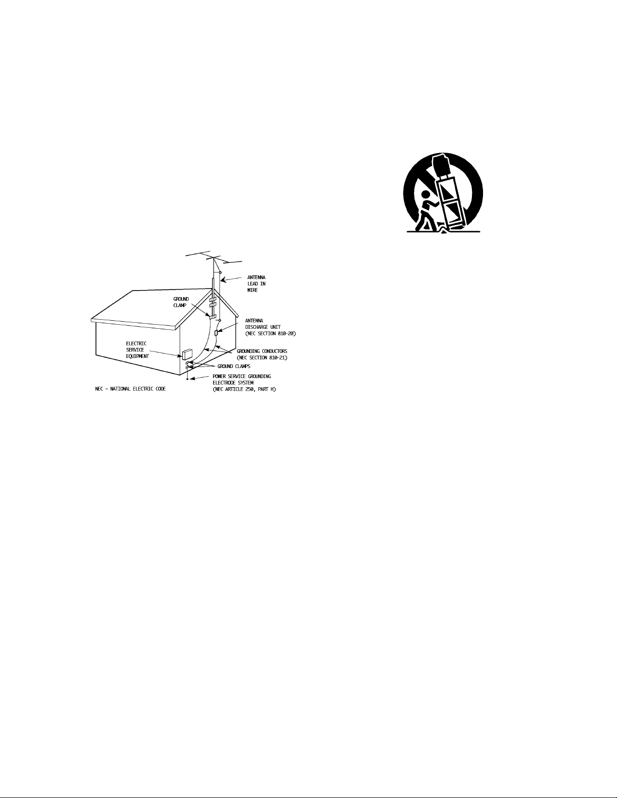
antenna system is grounded so as to provide some pro t e c t i o n
against voltage surges and built-up static charges. Section 810
of the National Electrical Code provides information with re s p e c t
to proper grounding of the mast and supporting stru c t u re ,
g rounding of the lead-in wire to an antenna discharge unit, size
of grounding conductors, location of antenna discharge unit,
connection re q u i rements for the grounding electro d e .
7 An outside antenna system should not be located in the
vicinity of overhead power lines or other electric light or
power circuits, or where it can fall into such power lines or
circuits. When installing an outside antenna system, extreme
care should be taken to keep from touching such power
lines or circuits as contact with them might be fatal.
EXAMPLE OF ANTENNA GROUNDING
AS PER NATIONAL ELECTRICAL CODE
8 TV sets are provided with ventilation openings in the cabinet
to allow heat generated during operation to be released.
Therefore:
— Never block the bottom ventilation slots of a portable TV
set by placing it on a bed, sofa, rug, etc.
— Never place a TV set in a “built-in” enclosure unless
proper ventilation is provided.
— Never cover the openings with a cloth or other material.
— Never place the TV set near or over a radiator or heat re g i s t e r.
9 To avoid personal injury:
— Do not place a TVset on a sloping shelf unless properly secure d .
— Use only a cart or stand recommended by the TV s e t
m a n u f a c t u re r.
— Do not try to roll a cart with small casters across thresh-
olds or deep pile carpets.
— Wall or shelf mounting should follow the manufacturer’s
instructions, and should use a mounting kit approved by
the manufacturer.
USE
10 Caution children about dropping or pushing objects into the TV set
t h rough cabinet openings. Some internal parts carry hazard o u s
voltages and contact can result in a fire or electrical shock.
11 Unplug the TV set from the wall outlet before cleaning. Do
not use liquid or an aerosol cleaner.
12 Never add accessories to a TV set that has not been designed for
Page 4

TABLE OF CONTENTS
Specifications . . . . . . . . . . . . . . . . . 44
CONNECTIONS
Connections Checklist . . . . . . . . . . . . . 5
Front Panel Diagrams . . . . . . . . . . . . . . 6
Rear Panel Diagrams . . . . . . . . . . . . . . 6
Cable or Antenna Connections . . . . . . . . . 7
V C R C o n n e c t i o n s. . . . . . . . . . . . . . . . 9
A u d i o / Video Connections. . . . . . . . . . . 1 0
D V D C o n n e c t i o n. . . . . . . . . . . . . . . . 1 1
C a m c o rd e r C o n n e c t i o n. . . . . . . . . . . . 1 1
GETTING STARTED
Remote Control . . . . . . . . . . . . . . . 1 2
Power . . . . . . . . . . . . . . . . . . . . . 13
Adjusting Volume . . . . . . . . . . . . . . . 13
Changing Channels . . . . . . . . . . . . . . 13
Remote Programming . . . . . . . . . . . . 14
CATV & Satellite Codes . . . . . . . . . . . . 14
VCR Codes . . . . . . . . . . . . . . . . . . 15
MENU FUNCTIONS
Using the Menu . . . . . . . . . . . . . . . . 16
Setup Menu
I n t ro d u c t i o n. . . . . . . . . . . . . . 1 7
Memorize Channels. . . . . . . . . . 1 7
Clock Time. . . . . . . . . . . . . . . 18
Set Day. . . . . . . . . . . . . . . . . 18
Audio/Video Connection
T V S p e a k e r s. . . . . . . . . . 1 8
AV Receiver. . . . . . . . . . 1 9
Audio Output. . . . . . . . . . 19
L a n g u a g e. . . . . . . . . . . . . . . 1 9
V- C h i p. . . . . . . . . . . . . . . . . . . . . 2 0
Channel Info Menu
Add or Delete Channels. . . . . . . . 24
Names for Channels. . . . . . . . . . 24
Names for Inputs. . . . . . . . . . . . 25
Super Quick View. . . . . . . . . . . 25
Advanced Features
Closed Captions. . . . . . . . . . . . 26
Timer Option. . . . . . . . . . . . . 2 6
Select Video Mute. . . . . . . . . . . 27
C o n v e rg e n c e. . . . . . . . . . . . . 2 7
Reset Factory Defaults. . . . . . . . . 27
Menu Functions (Continued)
Audio/Video Settings
AV Memory. . . . . . . . . . . . . . . 28
AV R e s e t. . . . . . . . . . . . . . 2 8
Audio Settings
B a s s. . . . . . . . . . . . . . 2 9
Tre b l e. . . . . . . . . . . . . . 2 9
B a l a n c e. . . . . . . . . . . . 2 9
S u rro u n d. . . . . . . . . . . . 2 9
Listen to. . . . . . . . . . . . 2 9
Video Settings
I R I S. . . . . . . . . . . . . . 3 0
C o n t r a s t. . . . . . . . . . . . 3 0
B r i g h t n e s s. . . . . . . . . . . 3 0
S h a r p n e s s. . . . . . . . . . . 3 0
Ti n t. . . . . . . . . . . . . . 3 0
C o l o r. . . . . . . . . . . . . . 3 0
Color Temp. . . . . . . . . . . 30
BUTTON FUNCTIONS
S l e e p. . . . . . . . . . . . . . . . . . . . . . 3 1
Vi d e o. . . . . . . . . . . . . . . . . . . . . . 3 1
A u d i o. . . . . . . . . . . . . . . . . . . . . . 3 1
Muting . . . . . . . . . . . . . . . . . . . . 3 1
E n t e r. . . . . . . . . . . . . . . . . . . . . . 3 1
C a n c e l. . . . . . . . . . . . . . . . . . . . . 3 1
Muting . . . . . . . . . . . . . . . . . . . . . 31
M e n u. . . . . . . . . . . . . . . . . . . . . . 3 1
O S D. . . . . . . . . . . . . . . . . . . . . . 3 1
10 Key Pad . . . . . . . . . . . . . . . . . . 32
Quick View. . . . . . . . . . . . . . . . . . . 32
Super Quick View. . . . . . . . . . . . . . . 32
I n p u t. . . . . . . . . . . . . . . . . . . . . . 3 2
C h a n n e l. . . . . . . . . . . . . . . . . . . 3 2
Vo l u m e. . . . . . . . . . . . . . . . . . . 3 2
VCR Buttons . . . . . . . . . . . . . . . . . . 32
L i g h t. . . . . . . . . . . . . . . . . . . . 3 2
PIP/POP
I n t ro d u c t i o n. . . . . . . . . . . . . . 3 3
Working with PIP/POP. . . . . . . . . 34
S o u rc e. . . . . . . . . . . . . . . . . 3 4
S w a p. . . . . . . . . . . . . . . . . . 3 4
Channel +/-. . . . . . . . . . . . . . 3 4
APPENDICES
Troubleshooting . . . . . . . . . . . . . . . . 35
Notes on Operation . . . . . . . . . . . . . . 36
Appendix 1 - Screen Shield. . . . . . . . . . 37
Appendix 2 - Bypassing the Parent Lock. . . 38
I n d e x. . . . . . . . . . . . . . . . . . . . . . 3 9
Limited Warranty . . . . . . . . . . . . . . . 42
Authorized Service Centers . . . . . . . . . . 43
Page 5
Connections 5
CONNECTIONS CHECKLIST - READ ME FIRST
The Connections Checklist section of this guide is a list of ideas to keep in mind while you
setup your new TV. It is designed to help us not-so-technically-minded individuals make our
connections properly. If you read this section and still can’t identify the plugs, connectors and
components you have, please ask someone for help in making your connections.
1) Always refer to the connection instructions in the
user’s guide for your components first. The
manufacturer will provide the most detailed
information about their products.
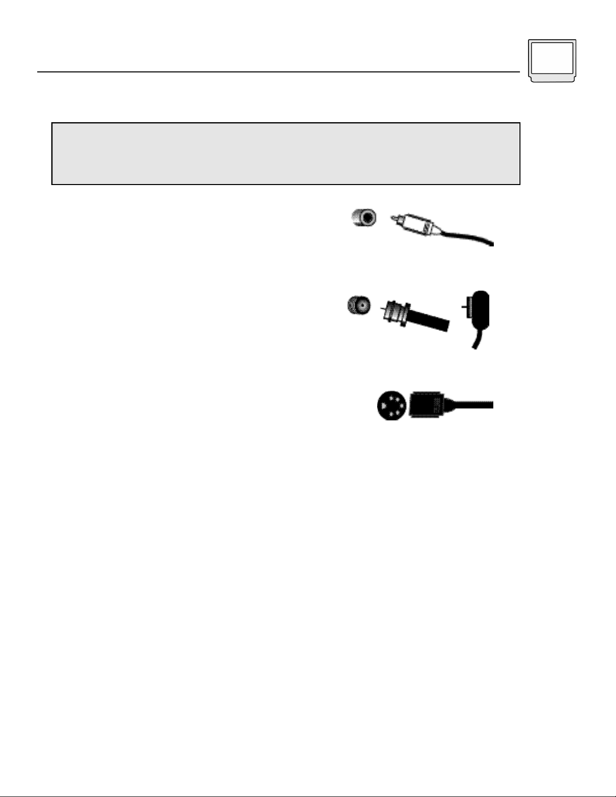
2) Know your jacks and plugs - most are color coded:
• Yellow plugs are Video connections
• Red plugs are Right Audio connections
• White (or black) plugs are Left Audio (or Mono)
connections. If your VCR is mono-sound, it will have
only a white or black plug, no second red one).
3) Perform one connection at a time. If you have
several accessories to connect, make sure each
connection is correct by checking to see that it works
properly before trying the next connection.
4) Unplug the power cord during each connection.
5) Follow the In and Out Concept. Remember In and
Out - the Output jack from one device will go to the
Input jack of the other. Read the jack panels, they are
all labeled.
A/V Input Plug
RF Connectors
S-Video Plug
Page 6
6 Connections
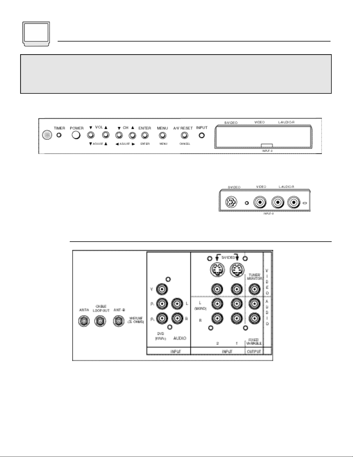
Shown below are illustrations of the Front and Rear panels of the D-Series Projection Televisions. Take a
moment to look at the illustrations to familiarize yourself with their layout. The Front Panel controls will be used
in the normal operation of your television, while the Rear Panel will be used to connect your television to your
other audio/video equipment. Detailed connection information can be found on the next several pages.
Front Panel
Front Panel for AV-60D501 and AV-50D501
Rear Panel
Front Input door open
Rear Panel for AV-60D501 and AV-50D501
Page 7
Connections 7
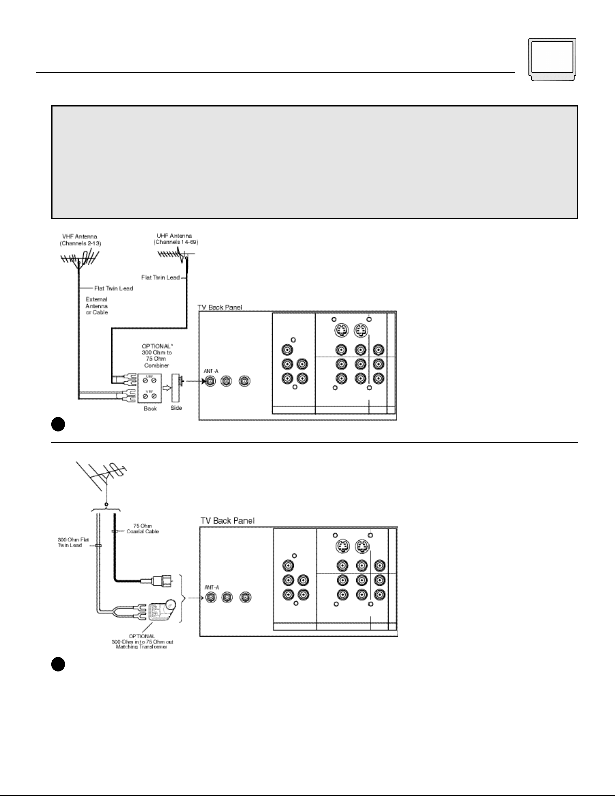
Cable or Antenna Connections
Before you can begin to watch your D-Series Projection television, you will need to connect it to an antenna
or cable outlet. The next four diagrams should cover most typical antenna or cable connections.
Use Diagram #1 to connect your television to an antenna with flat cable leads.
Use Diagram #2 to connect your television to an antenna with a coaxial cable lead OR to a cable system
that does not require you to use a cable box to receive any channels.
Use Diagram #3 or #4 to connect to a cable system that requires you to use a cable box to receive any or
all of you cable channels (i.e. to receive “premium” cable channels).
1) Connect the UHF and VHF
antenna leads to the UHF/VHF
combiner.
2) Press the combiner box onto
the ANT-A coaxial cable input on
the television’s back panel.
1
For Antenna with Twin Flat lead:
1) Connect the two 300 ohm leads
f rom the antenna to the transform e r.
2) Press the 75 ohm plug of the
transformer onto the ANT-A coaxial
cable input on the television’s back
panel.
For Antenna with a Coaxial Cable
lead or a Cable System that does
not require the use of a cable
box:
1) Connect the coaxial cable from
the antenna to the ANT-A coaxial
cable input on the television’s back
panel.
2
Page 8
8 Connections
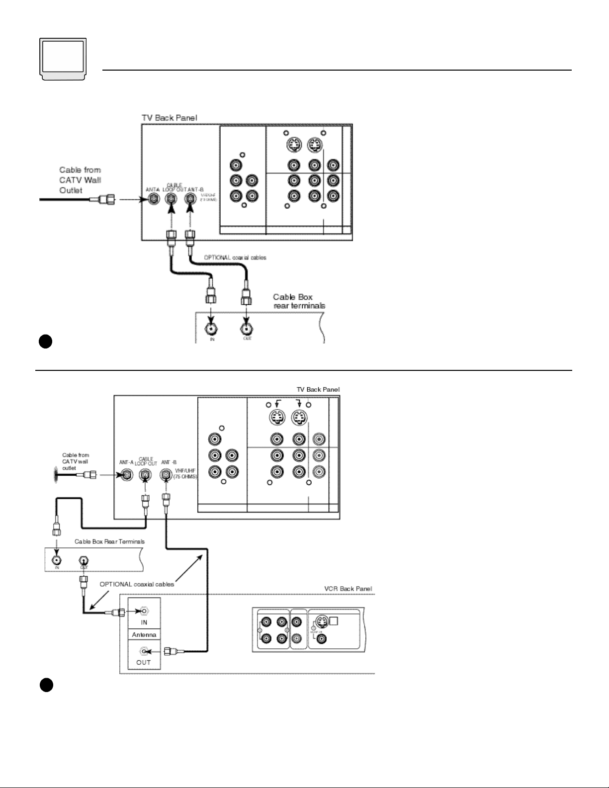
3
1) Connect the coaxial cable from the
cable television outlet to the ANT-A
input at the rear of the television.
2) Connect a coaxial cable from the
CABLE LOOP OUT jack at the rear of
the TV to the input jack on the cable
box.
3) Connect a coaxial cable out from
the Output jack on the cable box into
the ANT-B jack at the rear of the
television.
1) Connect the coaxial cable from the
cable television outlet to the ANT-A
input at the rear of the television.
2) Connect a coaxial cable from the
CABLE LOOP OUT jack at the rear of
the TV to the input jack on the cable
box.
3) Connect a coaxial cable OUT from
the cable box output to the Antenna In
coaxial jack on the VCR.
4) Connect a coaxial cable from the
Antenna Out jack on the VCR to the
ANT-B input at the rear of the
television.
4
Page 9
Connections 9
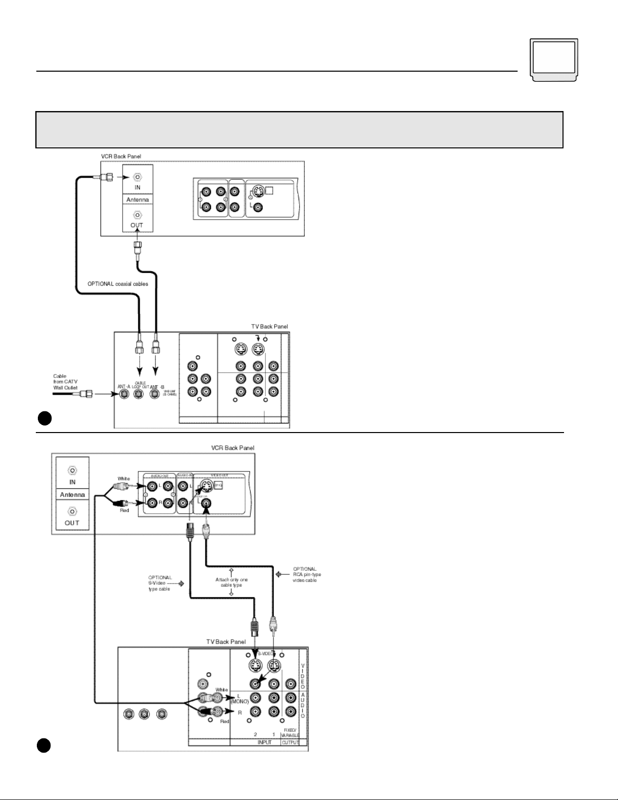
VCR Connections
Use the diagrams below to connect a VCR to your television. For an antenna or cable connection use
Diagram #1. For stereo-sound connection of an Audio/Video device, use Diagram #2.
1) Connect the coaxial cable from
the cable television outlet to the
ANT-A input at the rear of the
television.
2) Connect a coaxial cable from
the CABLE LOOP OUT jack at the
rear of the TV to the input jack on
the back panel of the VCR.
3) Connect a coaxial cable out
from the Output jack on the back
panel of the VCR into the ANT-B
jack at the rear of the television.
1
1) Connect a video cable from the
Video Out jack on the back of the
VCR to either the Video Input 1
or Video Input 2 jacks on the rear
panel of the television.
2) Connect the red audio cable
from the right Audio Output jack
on the VCR to the right Audio
Input jack at the rear of the
television.
3) Connect the white audio cable
from the left Audio Output of the
VCR to the left Audio Input jack at
the rear of the television.
S-Video Connection
To use the S-Video connections
for your VCR, plug an S-Video
cable into the output jack at the
rear of the VCR. Plug the S-Video
cable into one of the two S-Video
inputs at the rear of the television.
• Use either the S-Video or RCA-
2
type video cable connection, not
both, from any one device.
Page 10
10 Connections
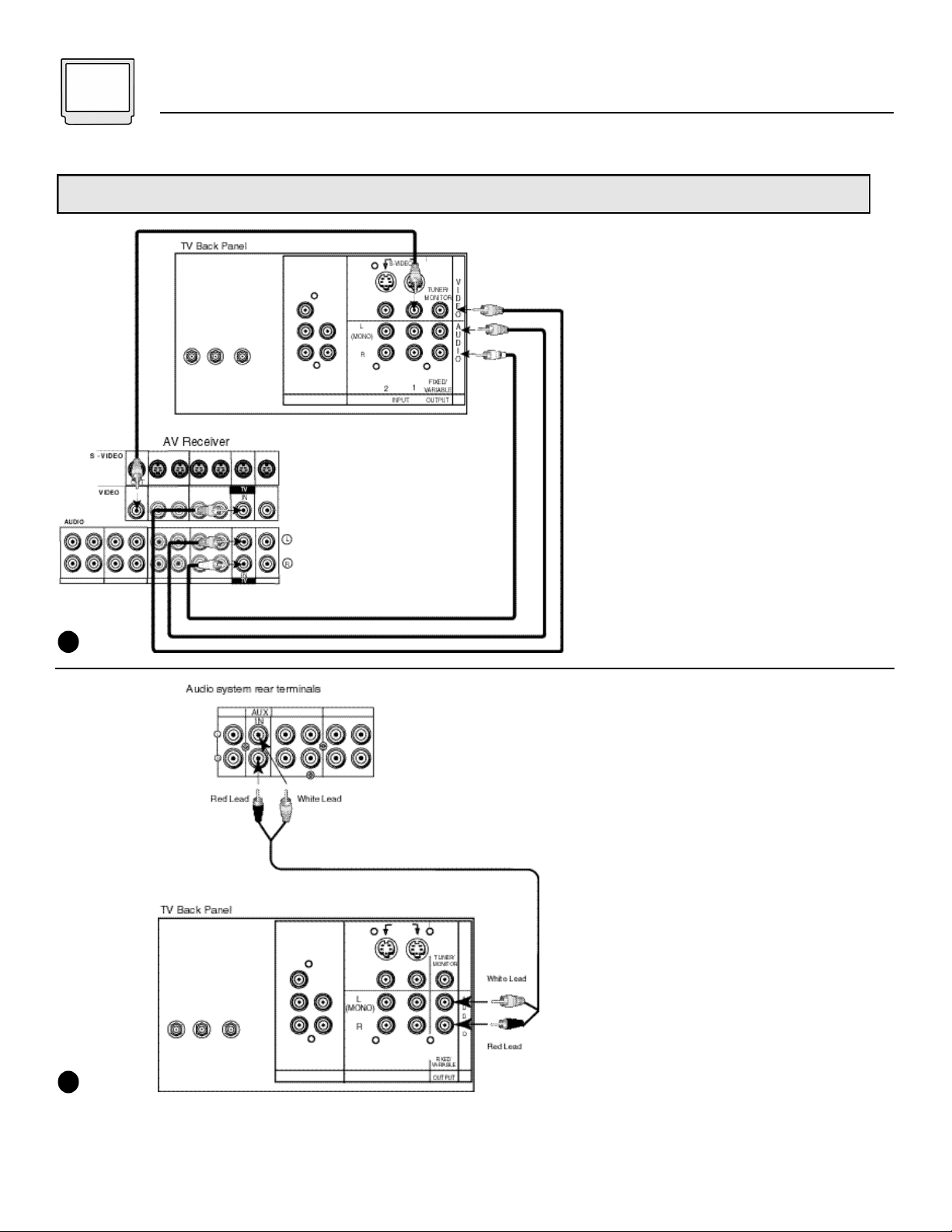
Audio/Video Connections - Stereo Systems
Use Diagram #1 to connect an AV Receiver, use Diagram #2 to connect to a stereo audio system.
1) Connect a video cable from the
Video Monitor Output jack on the
back of the AV receiver to the
Video Input 1 jack on the
television’s rear jack panel, using
a video plug cable.
2) Connect a video cable from the
Video Monitor Output jack on the
TV’s rear panel to the Video TV In
jack at the back of the AV
receiver.
3) Connect a set of audio cables
from the Audio Output jacks on
the TV’s rear panel in to the Audio
TV In jacks at the back of the AV
receiver. The red cable connects
the right output to the right input.
The white cable connects the left
output to the left input.
1
1) Connect the audio cables from
the Audio Monitor Output jacks on
the television’s rear panel to the
TV In or Aux In terminals at the
back of your audio system. The
red cable connects the right
Output to the right Input. The
white cable connects the left
Output to the left Input.
2) Turn off the TV’s internal
speakers with the option in the AV
Connection Menu (see page 18).
3) Set the audio system’s input to
the TV or AUX position to hear the
television audio through the audio
system’s speakers.
2
Page 11
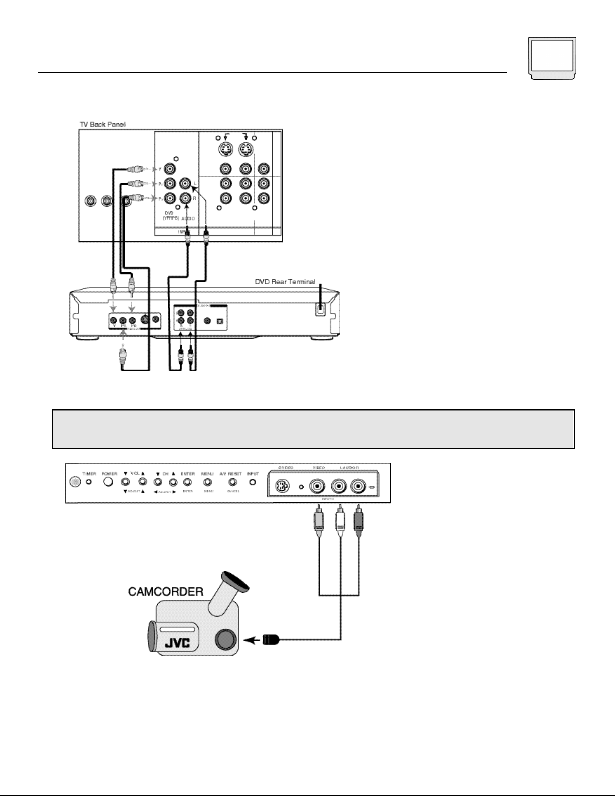
Connecting a DVD Player
Connections 11
1) Connect the Component Video
cables from the video output
jacks at the back of the DVD
player to the DVD input jacks at
the back of the television. Make
the connections in the following
order: Y to Y, PR to PR, PB to PB.
2) Connect a set of audio cables
from the Audio Output jacks at the
back of the DVD player to the
DVD Audio Input jacks located at
the back of the television next to
the Component Video Input
Jacks.
3) Connect the red audio cable
from the right Audio Output to the
right Audio Input.
4) Connect the white audio cable
from the left Audio Output to the
left Audio Input.
Connecting a Camcorder
You can quickly connect a camcorder to your D-Series Projection Television using the input jacks located under
the front panel door. If you wish, you may connect your camcorder to the rear input jacks by following these steps.
1) Lift gently on the front panel door
to open it.
2) Connect the yellow video cable
from the camcorder to the Video
Input jack on the TV.
3) Connect the white audio cable
from the camcorder to the right
Audio Input jack on the TV.
4) If your camcorder is a stereo
model, connect the red audio cable
from the camcorder to the left Audio
Input jack on the TV.
S-Video Connection
There is also an S-Video input
located at the front of the
television. If you have a camcorder
with an S-Video connection, you
may use this input. Use either the
S-Video or Video input jack, do not
use both.
• Other devices, such as game
consoles, may be connected
using the front input jacks.
Page 12
12 Getting Started
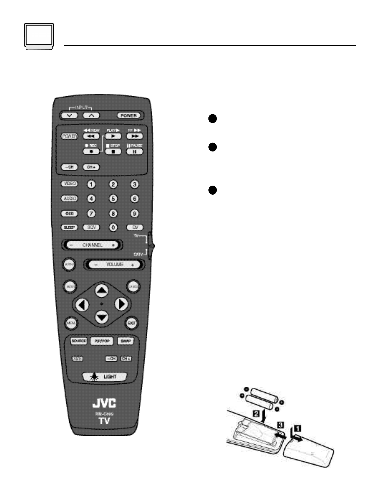
RM-C889
Changing the Batteries
Be sure to use only size AAb a t t e r i e s .
Push the tab on the remote's battery cover
1
and slide towards the bottom to remove it.
I n s e rt two AA batteries (supplied), carefully
2
noting the "+" and "-" markings on the
batteries and on the remote control. To avoid
a potential short circuit, insert the "-" end first.
When batteries are installed, slide the back
3
cover into place (until it clicks into position).
• If the remote control acts erratically, replace the
batteries. Typical battery life is six months to one
year.
• We recommend using alkaline batteries for
longer battery life.
When you change the batteries, try to complete the
task within three minutes. If you take longer than thre e
minutes, the remote control codes for your VCR,
Cable Box, and other devices may have to be re s e t
(page 14-15).
• When using the remote, be within 20 feet of the
television or other component.
• Do not drop the remote, or let it get wet or expose
it to a heat sourc e .
• When cleaning the remote use only a soft, damp
cloth. Do not use harsh chemical cleaners.
For more information on your remote control’s
many features, see pages 31 and 32 and your
Quick Setup Guide.
Page 13

Getting Started 13
POWER
• Press the PO W E R button on the remote control or the front panel of the TV. The power lamp will glow gre e n .
• Make sure the TV/CAT V switch on the remote is set to TV. Move the switch to CAT V only if you plan to operate
a cable box. On the CATV setting the remote will only operate the cable box functions.
• To turn the power off, press the Power button again. The power lamp will turn off .
• The On Timer lamp will blink when the On/Off Timer is set (page 26), even when the TV power is off.
ADJUSTING VOLUME
To control the volume level, use the VO L U M E+/- b u t t o n s on the remote control or on the TV's front panel. Use
the VO L U M E - button to lower the volume. Press the VOLUME+ button to raise the volume.
VOLUME :
Press the MUTING button to instantly turn the volume to zero. Press MUTING again to return to the previous
volume level.
|||||||
-------------------
CHANGING CHANNELS
10 key direct access
1
To move directly to a specific channel, press that channel's numbers on the remote's 10 key pad. For single-digit
channel numbers, press "0" then the channel number.
CHANNEL -/+ button
2
To scan through the channels, press either the CH A N N E L + or CH A N N E L - button. You will scan through the
channels in numerical ord e r.
• After you finish Memorizing Channels (page 17), all channels with poor or no reception will be removed fro m
m e m o ry. When you scan you will only receive channels in memory.
Quick View (QV)
3
The Quick View button will switch to the previous viewed channel. For example, select a channel. Then select a
d i ff e rent channel using the 10 key pad buttons. You can now flip back and forth between these two channels by
p ressing QV.
Super Quick View (SQV)
4
With Super Quick View you can add a list of your favorite channels into memory. You can then access this list at
any time by pressing SQV. Press SQV once to access your favorite channel list. Then each press of SQV will
access the next channel on your Super Quick View list. For information on adding or deleting channels to your
S Q V list, see page 25.
Page 14
14 Remote Programming
Victor
020, 259
002
011
000
040, 144
006, 008, 017, 277, 477
510
015, 040
011
040
021
003, 015
015, 040
015
001
258
040
001
310
012, 013
000
015
063
022, 153, 207
007
003
022, 056, 153, 191, 207
250
027, 063, 258
000, 054, 525
400
CODE
459, 520
460
459
CODE
772
775
775
749
627
791
701
627
566
639
790
053
053
1) Slide the 2-Way Mode Selector switch to CATV for
Cable/Satellite or TV for VCR.
2) Press the TV POWER (or VCRPOWER for VCR) and QV
buttons. Hold for at least three seconds and release.
3) Press TV POWER (or VCR POWER), see if the Cable/
Satellite box or VCR responds.
4) If there was a response, press QV. The operating
codes are now set. If there was no response,
repeat Step 3. If you repeat Step 3 more than 70
times without a response, use the remote control
which came with the equipment.
Search Codes Function:
Setting the CATV & VCR Codes
Cable Box / Satellite / VCR setup
1) Find the CATV/Satellite/VCR brand from the list of codes.
2) Slide the 2-way selector switch to “CATV” to program a
Cable/Satellite box or to “TV” to program VCR.
3) Press the POWER (for Cable box or Satellite) or VCR POWER
(for VCR) and QV buttons at the same time.
4) Enter the first 3-digit code number listed using the 10 key
pad.
5) Press the QV button to enter the code.
6) C o n f i rm the operation of the Cable Box/Satellite receiver or VCR.
• If your CATV/Satellite box/VCR does not respond to the first
code, try the others listed. If it does not respond to any
code, try the Search Codes Function.
CABLE BOXES
ABC
Allegro
Antronix
Archer
Belcor
Cable Star
Cabletenna
Cableview
Century
Citizen
Colour Voice
Comtronics
Contec
Eastern
Everquest
Focus
Garrard
GC Electronics
Gemini
General Instrument
Goldstar
Hamlin
Hitachi
Hytex
Jasco
Jerrold
Linsay
Magnavox
Memorex
Movie Time
Novaplex
NSC
Oak
Panasonic
Panther
Paragon
Philips
Pioneer
Popular Mechanics
Pulsar
RCA
Realistic
Recoton
001, 003, 007, 008, 011, 013, 014, 017
153, 315
022, 207
022, 153, 207
056
056
022
022
153
153, 315
025, 031
040
019
002
015, 040
400
153
056, 207
015
011, 276, 476
040, 144
009, 020, 034, 259
011
007
153, 315
003, 011, 012, 014, 015, 276, 476
440
027
000
063, 156
618
063, 156
007, 019
000, 021, 107
637
000
025, 027, 031, 153
023, 144, 533
400
000
021
207
400
CODE
Regal
Regency
Rembrandt
Runco
Samsung
Scientific Atlanta
Seam
Signal
Signature
SL Marx
Sprucer
Starcom
Stargate
Starquest
Sylvania
Tandy
Teleview
Texscan
TFC
Tocom
Toshiba
Tusa
TV 86
Unika
United Artists
United Cable
Universal
Videoway
Viewstar
Zenith
Zentek
AUDIO BOX E S
Jerrold
Scientific Atlanta
Starcom
S ATELLITE DISHES
Alphastar
Echostar
HTS
Hughes
Jerrold
Pace
Panasonic
Primestar
RCA
Sony
Toshiba
JVC
Page 15

Remote Programming 15
VCRs
Adventura
Aiko
Aiwa
Akai
American High
Asha
Audiovox
Beaumark
Bell & Howell
Broksonic
Calix
Canon
Capehart
Carver
CCE
Citizen
Colt
Craig
Curtis Mathes
Cybernex
Daewoo
Daytron
Dynatech
Electrohome
Electrophonic
Emerex
Emerson
Fisher
Fuji
Funai
Garrard
GE
Go Video
Goldstar
Gradiente
Grundig
Harley Davidson
Harmon/Kardon
Harwood
Headquarter
HI-Q
Hitachi
Jensen
JVC
KEC
Kenwood
KLH
Kodak
Lloyd
Lloyd’s
Logik
LXI
Magnavox
Magnin
Marantz
Marta
Matsushita
MEI
Memorex
MGA
MGN Technology
Minolta
Mitsubishi
Motorola
MTC
Multitech
NAD
NEC
Nikko
Noblex
Olympus
Optimus
Optonica
Orion
Panasonic
Penney
Pentax
Philco
Philips
Pilot
Pioneer
Portland
Protec
Pulsar
Quarter
Quartz
Quasar
Radio Shack
Radix
Randex
RCA
Realistic
Ricoh
Runco
Salora
Samsung
Sanky
Sansui
Sanyo
Scott
Sears
Sharp
Shintom
Shogun
Singer
Sony
STS
Sunpak
Sylvania
Symphonic
Tatung
Teac
Technics
Teknika
TMK
Toshiba
Totevision
Unitech
Vector
Vector Research
Video Concepts
Videosonic
Wards
XR-1000
Yamaha
Zenith
CODES
000
278
000
041, 049, 053, 061, 106
035
240
037
240
104
121, 184, 211, 295, 361
037
035
020
081
072, 278
037, 278
072
037, 047, 072, 240, 271
035, 041, 060
051, 240
020, 045, 278
020
000
037
037
032
000, 002, 036, 037, 043, 061, 068, 088,
121, 184, 208, 209, 211, 212, 278, 294,
295, 361, 479
047, 054, 066, 104
033, 035
000, 325
000, 325
035, 060, 065, 202
232
037, 038
000
195
000
038, 075
068, 072
046
047
041, 042, 065, 105, 166
041
067, 008, 041
037, 278
038, 041, 067
072
035, 037
000
208
072
037
035, 039, 081, 110, 149
240
035, 081
037
035
035
000, 035, 037, 039, 046, 047, 048, 104, 240
043, 061
240
042, 105
043, 061, 067, 075, 173
035, 048
000, 240
000, 072
058
038, 040, 041, 067, 104
037
240
035
037, 048, 058, 104, 162, 432, 454
062
295, 479
035, 077, 162, 225, 454
035, 037, 038, 040, 042, 054, 240
042, 065, 105
035
035, 062, 081, 110
037
058, 067
020
072
039, 051
046
046
035, 077, 162, 454
000, 037, 325
037
037
042, 060, 065, 077, 105, 106, 149, 202
000, 035, 037, 046, 047, 048, 062, 066,
104, 240
034, 253
039
075
045, 051, 053, 240
039, 048
041, 067, 271
046, 047, 104, 240
043, 045, 121, 184, 210, 211, 212
008, 035, 037, 042, 046, 047, 054, 066, 067,
104, 105
048, 062
072
051, 240
072
032, 033, 034, 035, 253
042
253
000, 035, 043, 081, 110
000, 325
041
000, 041
035, 162
000, 035, 037
036, 208, 240
043, 045, 066, 210, 212, 366
037, 240
240
045
038, 040
040, 045, 061
240
000, 035, 042, 047, 048, 060, 062, 072,
149, 212, 240
000, 035, 072
038
033, 034, 039
Page 16

16 Using the Menu
Using this Guide
C e rtain symbols are used throughout this guide to help
you learn about the features of your new television. The
ones you will see most frequently are :
Up and Down arrows mean press the UP o r DO W N
a rrow buttons on the remote control. Pressing the UP
or DO W N buttons let you:
• Move vertically in a main menu scre e n
• Move through a submenu scre e n
• Move to the next letter, number, or other choice in a
s u b m e n u
• Back up to correct an erro r
Left and right arrows mean press the LE F T o r RI G H T
a rrow buttons on the remote control to:
• Select a highlighted menu item
• Select an item in a submenu
• Select numbers in certain menu options
The "Press Button"icon means you should
p ress the button named on your remote control.
(Button names appear in SM A L L CA P I TA L LE T T E R S. )
Setup Menu
2
3
V-Chip Menu
Channel Info Menu
4
The ‘Helping Hand’ points to the highlighted or
selected item in a menu.
The Onscreen Menus:
To bring up the onscreen menu, press the MENU button
on the remote control. The item that appears with the
‘Helping Hand’ next to it is the one currently selected.
The text highlighted in yellow shows which option in the
selected item is currently active.
Note: The menus shown in this guide are illustrations for
reference purposes, not actual representations of
onscreen menus.
Main Menu
1
5
Advanced Features Menu
6
A/V Settings Menu
Page 17

Setup Menu 17
Introduction
The Setup Menu is designed to help you get your
television ready to watch right away. It is
recommended that you complete all the items
in the Setup Menu before you begin using
your new TV. The Setup menu items include:
• Memorize Channels
• Clock Time
• Set Day
• AV Connection (Home Theater)
• Language
Descriptions of each of the Setup Menu features
and how to operate them appear on the next three
pages.
Memorize Channels
In Memorize Channels, the TVautomatically scans
t h rough all available channels, memorizing the active
ones and skipping over blank ones or channels with
weak signals. This means when you scan (using the
CH A N N E L +/- b u t t o n s ) you will receive only clear,
active channels.
P ress the ME N U b u t t o n
To SETUP
P ress the EN T E R b u t t o n
Memorize Channels - Continued
You can memorize channels from the following inputs:
To move to the Input option
To activate
To select the Input you want to have
memorized
P ress the EN T E R button to begin Memorization
Memorization will take 1 to 2 minutes.
When Memorization is complete the screen will
return to the Setup MENU. To exit, press Menu to
return to the main menu or press EXIT to return to
normal television viewing.
• You can stop Memorization at any time by
pressing CANCEL. Any channels memorized before
cancelling will remain in memory.
To MEMORIZE CHANNELS
NOTES:
• You may change your Setup Menu preferences at any time.
• More than one input may be memorized. Use the steps above for each input you wish to memorize.
Page 18

18 Setup Menu
Clock Time
Before you use any of your TV’s timer functions,
you must first set the clock.
Press MENU
To SETUP
Press ENTER
To CLOCK TIME
To move to the time field
To set the time
To exit the field when the correct time is
set
Press MENU to return to the main menu or
press EXIT to return to normal television
viewing
Set Day
You also need to set the television to the current
day. To set the date:
AV Connection
The AV Connection Menu lets you set your
Television up to work with the other pieces of your
home entertainment system.
Press MENU
To SETUP
Press ENTER
To AV CONNECTION (Home Theater)
Press ENTER to access AV Connection
There are three settings which you can adjust to
suit your preferences and other equipment:
• TV Speakers (Internal Speakers)
• AV Receiver at Input 1
• Audio Output (TV Volume Control)
Press MENU
To SETUP
Press ENTER
To SET DAY
To move to the time field
To the day
To exit the field when the correct day is
set
Press MENU to return to the main menu or
press EXIT to return to normal television
viewing
To select an option. Connection options are :
TV Speakers
This option allows you to turn off your TV’s internal
speakers. Select this option if you plan to send the
TV’s audio to your home stereo or a SurroundSound AV receiver.
To speaker option
To turn TV Speakers ON or OFF
To save setting and exit field
Warning - If you change the TV Speaker setting
from OFF to ON, make sure the volume is turned
down very low! Otherwise, when the option is
turned on, the volume could be extremely loud
and could damage the TV’s speakers.
• See the chart on page 19 for a list of
connections and their proper AV settings.
NOTES:
• You will have to reset the clock after a power interruption of 90 seconds or longer.
• You must set the clock before operating any timer functions.
Page 19

Setup Menu 19
AV Connection - Continued
AV Receiver at Input 1
Use this option if you connect an AV Receiver’s
video output to the TV’s Input 1. Set the option to
YES to prevent a possible feedback loop which
could damage your equipment.
To activate
To Set AV Receiver at Input 1 to Yes or No
To save setting and exit field
• See the chart at the bottom of the page for a list
of connections and their proper AV settings.
Audio Output
You have the option of using either the television’s
remote, or your AV receiver’s remote to control the
TV volume, when the set is connected to your
home theater system. Set Audio Output to FIXED if
you wish to use the AV receiver’s remote. Select
VARIABLE if you want to use your TV’s remote to
control the volume.
To activate
To select Audio Output: Fixed or Variable
To save setting and exit field
• See the chart below for a list of connections and
their proper AV settings.
Language
You can choose to view your onscreen menus in
either English or Spanish.
Press MENU
To SETUP
Press ENTER
To Language
To move to the language field
To select English or Spanish (language will
change with selection)
To exit the field
Press MENU to return to the main menu or
press EXIT to return to normal television
viewing
Your initial setup is now complete. Please keep in
mind that these settings may be changed at any
time by accessing these menus.
The next few pages of the guide deal with setting
up your V-Chip guidelines. If you wish to begin
your television viewing right away, skip ahead to
Channel Info Menu on page 24.
Page 20

20 V-Chip
V-Chip
Your TV is equipped with V-Chip technology which
enables TVP a rental Guideline and Movie (MPA A )
Guideline controls. V-Chip technology allows you to
p rogram your TVto receive, or not to receive,
p rograms based on content according to the
guidelines you set. Programs which exceed your
ratings limits will be blocked from viewing.
When a viewer attempts to watch a blocked pro g r a m ,
a passcode message screen like this appears:
THE TV IS LOCKED.
V-CHIP LOCKED THE PROGRAM
BECAUSE THE RATING IS
TV-PG
- - - -
-
ENTER YOUR PASSCODE USING
NUMBER BUTTONS AND PRESS ENTER
TO WATCH THE PROGRAM.
To watch a blocked program, enter the passcode
using the 10 key pad.
To set up the TV Parental
Guideline Ratings:
P ress the ME N U b u t t o n
To V-CHIP PARENT LOCK
Press ENTER
V-CHIP PARENT LOCK
TO GO TO THE MENU,
ENTER THE PASSCODE.
USE THE NUMBER BUTTONS,
THEN PRESS ENTER.
- - - -
-
The following screen will appear.
Enter the four digit passcode using the 10-key
pad. When the correct code is entered, the V-Chip
Menu will appear. All ratings options will be set
using this menu.
The first option on the V-Chip Menu is to set the
TV Ratings guidelines. A description of each of
the TV ratings categories appears in the next
column.
U.S. PARENTAL RATING SYSTEMS
Programs with the following Ratings are
appropriate for Children.
❒ T V-Y is Appropriate for All Children.
P rograms are created for very young viewers
and should be suitable for all ages, including
c h i l d ren ages 2 - 6.
❒ TV-Y7 is for Older Children.
Most parents would find such programs
suitable for children 7 and above. They may
contain some mild fantasy violence or
comedic violence, which children should be
able to discern from reality.
P rograms with the fo l l owing Ratings are
designed for the entire audience.
❒ TV-G stands for General Audience.
Most parents would find these programs
suitable for all age groups. They contain little
or no violence, no strong language, and little
or no sexual dialog or situations.
❒ TV-PG – Parental Guidance Suggested.
May contain some, but not much, strong
language, limited violence, and some
suggestive sexual dialog or situations. It i s
recommended that parents watch these
programs first, or with their children.
❒ TV-14 – Parents Strongly Cautioned.
Programs contain some material that may
be unsuitable for children under the age of
14 including possible intense violence,
sexual situations, strong coarse language,
or intensely suggestive dialog. Parents are
cautioned against unattended viewing by
children under 14.
❒ TV-MA – Mature Audiences Only.
These programs are specifically for adults
and may be unsuitable for anyone under 17
years of age. TV MA programs may have
extensive V, S, L, or D.
Viewing Guidelines
• V/FV is for VIOLENCE/FANTASY VIOLENCE
• S stands for SEXUAL CONTENT
• L stands for strong LANGUAGE
• D stands for suggestive DIALOG
Page 21

V-Chip 21
Directions to Set TV Ratings:
To set a maximum allowed rating with the TV
Rating option:
To the Rating column
To the select the maximum rating
Once you have set a maximum rating, you can
also program the television to block certain
types of material based on the viewing
guidelines, such as programs with Violence or
Language warnings. (The television is shipped
with all categories set to ALLOW).
To the category you wish to block
To activate
To BLOCK or ALLOW
Use these steps for each of the individual
guideline categories you wish to change. You
may choose to Block or Allow the viewing of
any or all the individual categories.
If you access a channel showing blocked
programming, you will be asked for the
passcode to unblock the channel. If you wish to
watch the channel, enter the passcode.
Notes About Unrated Programs:
Unrated programming refers to any
programming which does not contain a rating
signal. Programming on television stations
which do not broadcast rating signals will be
placed in the “Unrated Programming" category.
Some examples of Unrated programs:
Emergency Bulletins
Locally Originated Programming
News
Political Programs
Public Service Announcements
Religious Programs
Sports
Weather
Some Commercials
• TV programs or movies that do not have rating
signals will be blocked if the Unrated Category
is set to BLOCK.
Directions to Block Unrated
Programs:
Some programming you receive will not be
broadcast with a ratings signal. You may
choose to block this programming if you wish.
To block unrated programming:
To the Programs not rated column
To activate
To BLOCK or ALLOW
If you set this option to BLOCK, the passcode
screen will appear when an unrated program is
tuned in.
Special Note about Ratings
Some programs are not broadcast with a
ratings signal. Therefore, even if you setup
V-Chip ratings limits, these programs will
not be blocked. Parents are cautioned to
preview the contents of these programs or
movies.
NOTES:
Once unblocked, a station will remain unblocked until the television is turned off.
Page 22

22 V-Chip
Movie Ratings
In addition to ratings information about
television programs, your TV can also block
programming based on Movie Rating
information. This is the rating system you will
most often find on premium cable movie
channels or on pay-per-view channels. Brief
descriptions of each rating appear below.
❒ OFF.
The V-Chip movie ratings filter is off.
❒ G – General Audience.
In the opinion of the review board, these
films contain nothing in the way of sexual
content, violence, or language that would be
unsuitable for audiences of any age.
❒ PG – Parental Guidance.
P a rental Guidance means the movie may
contain some contents such as mild violence,
some brief nudity, and strong language. The
contents are not deemed intense.
❒ PG-13 – Parents Strongly Cautioned.
Parents with children under 13 are cautioned
that the content of movies with this rating
may include more explicit sexual, language,
and violence content than movies rated PG.
❒ R – Restricted.
These films contain material that is explicit in
nature and is not recommended for
unsupervised children under the age of 17.
❒ NC-17 – No One Under 17.
These movies contain content which most
p a rents would feel is too adult for their childre n
to view. Content can consist of stro n g
language, nudity, violence, and suggestive or
explicit subject matter.
❒ X – No One under 18.
Inappropriate material for anyone under 18.
D i rections to Set Movie Ratings:
To set a maximum allowed movie rating:
To the Movie Rating column
To activate
To select the maximum rating
All movies rated at or above the rating you have
set will be blocked. To watch a blocked movie,
enter the passcode when it is requested
onscreen. You may change your Movie Ratings
preference whenever you wish.
NOTES:
In order for V-Chip settings to take effect, V-Chip settings must be turned ON in the V-Chip menu.
You can automatically unblock all of your restrictions by turning V-Chip settings OFF in the V-Chip menu.
Page 23

V-Chip 23
Set V-Chip/Lock Time
You have the option of setting the V-Chip ratings
to work for only a portion of the day. You may also
lock all of the television stations (regardless of
V-Chip ratings) for a period of the day.
To set a V-Chip or Lock time, use the arrows to
move to the V-CHIP HOURS/LOCK BY TIME
option at the bottom of the V-Chip menu and
press Enter.
Note: If no V-Chip or Lock time is set, any V-Chip
ratings entered will be active 24 hours a day.
To set the V-Chip Timer:
To V-CHIP START TIME
To time field
To set time
To confirm time
To V-CHIP STOP TIME
To time field
To set time
To confirm time
Your V-Chip operation times are now set.
Lock By Time
If you would rather block ALL channels during a
certain time period, use the Lock by Time option.
To set Lock by Time:
To LOCK TIME
To time field
To set time
To confirm time
To UNLOCK TIME
To time field
To set time
To confirm time
Your Lock and Unlock times are now set. To
activate the time lock:
To LOCK BY TIME
To ON or OFF
To turn lock ON or OFF
Press MENU to return to the Menu, or EXIT to
return to normal television viewing.
Accessing V-Chip Information:
To access Rating information about a certain
program, press the OSD button while viewing
that program. A display like this will appear
onscreen at the top left corner:
NOTES:
Appendix B contains instructions on how to bypass the parent lock.
Page 24

24 Channel Info Menu
Channel Info Menu
The Channel Info Menu lets you modify the list of
channels Memorized by the Memorize Channels
feature. The following options will let you add or
delete channels from memory, add on-screen
names to channels or inputs and select channels
to include in your Super Quick View (SQV) list.
To access the Channel Info Menu:
P ress the ME N U button to display the Main
M e n u
To CHANNEL INFO
Press ENTER to select
Selecting Names for Channels
You can add a name to any or all of the memorized
channels. This name, such as the channels call-sign
(i.e. WCBS), will be displayed on screen for a few
seconds whenever that channel is selected. The
name may be up to four characters long.
With the Input and Channels fields set to the channel
you wish to name:
To move to NAME
To move to NAME field
To select the first character. Characters avail
able are: letters A-Z, Numbers 0-9, and
symbols (! . & / : * - , and < blank >)
P ress EN T E R to save character and move to
the next
Repeat until all four spaces are filled. For names
under four characters insert <blank> spaces.
To change a character:
To the character you wish to change
To choose the Channel Info option you
want. The options are described in the
following sections:
Adding or Deleting Channels
With this option you can remove any unwanted
channels that were memorized during Memorize
Channels. You can also add channels to the
memory which were not included in the original
scan, such as new channels or channels that
were too weak to be received clearly during
Memorize Channels.
To the CHANNEL column
To the channel field
To select a channel to add or remove
To exit the field
To the Memory column
To the memory field
To the add or remove the selected channel
P ress CA N C E L
You may now re-input the character. To delete the
e n t i re name move to the first space and p re s s
CA N C E L.
You may name as many of the channels as you wish.
When you are finished, press ME N U to re t u rn to the
main menu, or EX I T to re t u rn to normal television
v i e w i n g .
EXIT when finished
NOTES:
Some cable systems experience interference from radio frequencies on cable Channel 95. You may choose to delete this
channel from memory using the steps listed above.
Page 25

Channel Info Menu 25
Selecting Names for Inputs
You may also give names to the devices connected
to the TV’s inputs. There are 15 names available for
the inputs, they are: V C R 1 ;V C R 2 ;DV D ;L A S E R ;
S AT (for satellite); C A B L E ; C A M (for camcord e r ) ;
G A M E ;V H S ; S - V H S ; D T V; W E B ; M A I N ; AU X ;a n d
S U RV (for a surveillance or security camera).
To name the inputs, from the CHANNELI N F Om e n u :
To Input
To field
To select Input-1, Input-2, Input-3
To re t u rn to left column
To Name
To field
To select Input name from list
To save name and exit
You may name as many of the inputs as you wish.
When you are finished, press ME N U to re t u rn to the
main menu, or EX I T to re t u rn to normal television
v i e w i n g .
Selecting Super Quick View (SQV)
Channels
Super Quick View (SQV) lets you put together a list
of your favorite stations which can be accessed by
p ressing the SQV button on your remote contro l .
When you turn to a channel on your SQVlist, the
letters “SQV” will display on screen along with the
channel number for a few seconds.
To Add SQV Channels using the re m o t e
c o n t ro l
Tu rn to the channel you wish to add either with the
CH A N N E L +/- or 10 key buttons.
P ress and hold SQV for three seconds
The letters “SQV” will appear on screen showing
that this channel has been added to your SQV list.
To Remove SQV Channels using the
remote control
Tu rn to the channel you wish to add either with the
S Q V, CH A N N E L +/- or 10 key buttons.
While “SQV” is displayed on screen, press
CA N C E L
The letters “SQV” will disappear from the scre e n
showing that this channel has been deleted from
your SQV list.
• CA N C E L must be pressed while “SQV”is on screen.
P ressing CA N C E L after “SQV” has disappeared will
not remove the channel.
Using SQV
To access your SQV list, press the SQV button on the
remote. To move to the next channel on your SQVl i s t ,
p ress SQV again.
NOTES:
SQV channels can be memorized only from Input-1 and Input-2.
Page 26

26 Advanced Features
Advanced Features
The Advanced Features menu lets you adjust
some of the other features of your television. The
menu options are described in the following
sections. To access the Advanced Menu:
Press MENU to display the Main Menu
To Advanced Features
Press ENTER to access the Advanced
Features menu
Closed Captions
Your television can display Closed Caption
content when included with a broadcast. There
are two types of Closed Captions broadcast:
Standard, which follows the dialog of the
characters on screen and usually displays along
the bottom of the screen, and Text which provides
additional information included with a broadcast
and displays in the center of the screen. To set up
your Closed Captioning options:
To Closed Captions
Closed Captions - Continued
• You will have a choice of four closed caption
channels (CC1 - CC4) and four text channels
(Text1 - Text4). Closed Captions are usually found
on channel CC, Text is usually found on channel
Text1. The other channels are for future use.
To select the option: CC1 - CC4,
Text1 - Text4, ON IF MUTE, or OFF
• On if Mute will display the signal of CC1
whenever you press MUTE on the remote control.
To leave the Closed Caption field
Your selection will be activated. You may also
select a background color for the Closed Caption
text. You may choose either a black or gray
background.
To CC BACKGROUND
To the background color field
To select either GRAY or BLACK
Once your Closed Captions preferences are set
you may return to the Advanced Features Menu by
pressing MENU, or return to normal television
viewing by pressing EXIT.
Timer Option
The Timer will automatically turn your TV on and
tune it to a pre-selected channel at a time you
select. Access the Timer settings by selecting the
Timer option from the Advanced Features menu.
To the Closed Captions options field
NOTES:
Closed Captions subtitles are programmed by the broadcast channel. Any misspellings are the fault of the broadcaster and
not a malfunction of the television. Closed captioning may not work correctly if the signal being received is weak or if you are
playing a video tape. Most broadcasts containing Closed Captioning will display a notice at the start of the program.
On/Off Timer cannot be set to locked or guarded channels.
In order for the On/Off Timer to work, the clock must be set. After a power interruption Timer settings must be reset.
Page 27

Advanced Features 27
Timer - Continued
Set Time
To the time field
To set the time
To save and move to the next option
Use this procedure to input your Day, Input and
Channel settings. When the Timer is set as you
wish, move to the Timer field
To ON/OFF
To turn the timer ON or OFF
If you turn this setting to ON, your Timer settings
will go into effect. If you turn this setting to OFF, any
timer settings will be cancelled. When you have
finished, press MENU to return to the Advanced
Features menu, or EXIT to return to normal television viewing.
When the Timer turns the set on, a message will
appear on screen. If you want the TV to stay on,
press any button on th remote or TV’s front panel. If
you do not press a button within five minutes of the
Timer turning on, the TV will shut off.
Convergence - Continued
To Convergence
To Red Convergence (the following screen
will appear)
Select Red Convergence. The adjustment screen
will now appear.
Using the arrow keys, align the color you see until
only a single white cross is displayed. The cross
shows the beams are correctly aligned.
Select Video Mute
Video Mute displays a blue screen instead of static
whenever the TV is tuned to a weak or empty
channel.
To Video Mute
To turn Video Mute ON or OFF
Convergence
Your JVC projection television contains three
picture tubes with large diameter lenses that
project images onto a screen to form your
television pictures. Each tube projects one color:
red, green, or blue. The three tubes were carefully
aligned by JVC at the factory to provide you with
the best picture quality possible.
With the convergence feature, you have the ability
to adjust these picture tubes should you feel they
are out of alignment..
To access the Static Convergence options (from
Advanced Features menu):
Press VIDEO to switch from Red to Blue
Using the arrow keys again, align the color you
see until only a single white cross is displayed.
The cross shows the beams are correctly aligned.
Press MENU to exit
Reset Factory Defaults
If you have performed any Convergence
adjustments, but later wish to undo them, you can
reset the factory default adjustments to the picture
tubes.
To Reset Factory Default
Press ENTER to operate
The Convergence will reset to the defaults set at
the factory.
Press MENU to return to the menu or EXIT
to return to normal television viewing
Page 28

28 Audio/Video Settings
Adjusting the Audio and Vi d e o
S e t t i n g s
You can further customize your television’s sound and
p i c t u re by adjusting the audio and video settings. Yo u
have the ability to select one of five preset
adjustment settings or make your own adjustments
to a number of individual audio or video settings.
To access the Audio/Video Settings menu:
Press MENU to display the Main Menu
To AUDIO/VIDEO SETTINGS
Press ENTER to access the Audio/Video
Settings menu
AV Memory
Your television comes with five pre-set groups of
audio and video adjustments designed to give the
best picture quality for different conditions. The
five settings are:
AV Memory - Continued
To AV MEMORY
To activate
To choose an AV Memory setting:
STANDARD, DAYLIGHT, EVENING,
HOME TH., or DVD
• You can select a different memory setting for
Input-1, Input-2, and Input-3.
Each setting can be further adjusted using the
audio and video setting adjustments described on
the next page.
AV Reset for Standard
At any time you can automatically reset your
television’s audio and video settings to the
Standard settings “memory” set at the factory.
To AV Reset for Standard
Press ENTER to reset settings to factory
Standard
Audio/Video preferences will be reset to the
original settings.
STANDARD - The factory settings the television
was shipped with. This is the setting that will be in
effect when the set is first turned on.
DAYLIGHT - Settings designed to give the best
picture quality during daylight hours.
EVENING - Settings designed to give the best
picture quality during evening hours.
HOME TH. - Settings designed to give the best
picture and sound quality when used as part of a
home entertainment system
DVD - Settings designed for optimal performance
with a DVD player.
Page 29

Audio/Video Settings 29
Audio Settings
You have the option of making further adjustments
to your television’s sound. These adjustments can
be made at any time. The adjustments include
individual areas of sound quality to stereo and
surround sound effects.
To change the Audio Settings, from the
Audio/Video Settings Menu:
To AUDIO SETTINGS
Press ENTER To activate
or, from your remote control,
Press AUDIO
An adjustment bar or option will appear onscreen.
The individual Audio Settings are as follows:
BASS
Lets you increase or decrease the amount of low-
frequence sound.
To increase the bass
To decrease the bass
To save and move to the next setting
TREBLE
Lets you increase or decrease the amount of high-
frequence sound.
To increase the treble
To decrease the treble
To save and move to the next setting
BALANCE
Lets you adjust the distribution of sound between
your TV’s left and right speakers.
To shift the balance to the right
To shift the balance to the left
To save and move to the next setting
Audio Settings - Continued
SURROUND
Creates simulated stereo and surround sound
effects. The three settings are:
OFF - Choose this setting if you do not want any
surround effects. This is also the setting to use if
you are connected to an A/V Receiver with Dolby
Pro Logic Surround or Dolby Digital Surround.
SIMULATED STEREO - Choose this setting if you
are watching a non-stereo program. The television
will create a simulated stereo sound effect using
the TV’s speakers.
SURROUND - Choose this setting if you are
watching a stereo broadcast. The TV’s internal
speakers will create a “surround” effect, making
the sound seem like it is all around you.
LISTEN TO
Many broadcasts today contain several audio
tracks. The Listen to option selects which audio
track you wish to hear. Settings are:
STEREO - This is the default setting. Stereo
broadcasts will play in stereo, mono broadcasts
will play in mono.
SAP - (Second Audio Program). This setting will
play the SAP. (if one is included in a broadcast).
SAP may be dialog in second language, or
additional information such as a weather report.
Programs with SAP, display a “SAP” logo at the
start of the broadcast.
MONO - Use this setting if you are receiving a
weak stereo signal to eliminate excess noise.
Otherwise it is best to use the “Stereo” setting
(mono broadcasts received will be played in
mono).
LEVEL SOUND
This option automatically equalizes the volume of
broadcasts, providing for a consistent sound level.
Use this to eliminate overly-loud audio in
commercials during programs. For the best audio
fidelity of music programs, you may want to set
this option to Off.
NOTES:
You may leave the audio settings at any time by pressing EXIT. If you do not make any adjustments to the audio settings for
20 seconds, the display will turn off and any adjustments you made will be saved.
Dolby, AC-3, Pro Logic and the double-D symbol are trademarks of Dolby Laboratories Licensing Corporation. Copyright
1992 Dolby Laboratories, Inc. All rights reserved.
Page 30
30 Audio/Video Settings
Video Settings
You have the option of making further adjustments
to your television’s video display qualities. These
adjustments can be made at any time. The
adjustments include individual areas of video
quality to overall picture display effects.
To change the Video Settings, from the
Audio/Video Settings Menu:
To VIDEO SETTINGS
Press ENTER to activate
or, from your remote control,
Press VIDEO
An adjustment bar or option will appear onscreen.
The individual Video Settings are as follows:
IRIS
The Intelligent Room Illumination Sensor. IRIS
(when activated) detects the level of light in the
room and automatically makes adjustments to the
picture’s contrast and brightness to give the best
picture quality.
To turn IRIS ON or OFF
To save and move to the next setting
CONTRAST
Provides a measure of white-to-black levels in the
picture. Low contrast will show a variety of dark
shades, while high contrast will make the picture
seem more vibrant overall.
To increase the contrast
To decrease the contrast
To save and move to the next setting
• When IRIS is on, Contrast will display as “IRIS”.
BRIGHTNESS
Lets you adjust the overall brightness of the
screen image.
To increase the brightness
To decrease the brightness
To save and move to the next setting
Video Settings - Continued
SHARPNESS
Lets you adjust the overall brightness of the
screen image.
To increase the brightness
To decrease the brightness
To save and move to the next setting
TINT
Lets you adjust the ratio of red-to-green displayed
in the picture.
To make the picture appear more red
To make the picture appear more green
To save and move to the next setting
COLOR
Lets you adjust the overall color intensity of the
screen image.
To increase the color intensity
To decrease the color intensity
To save and move to the next setting
COLOR TEMP
Color temperature is a measure of how intense the
white light in the television picture appears. This
intensity has an effect on the overall appearance
of the television picture. There are three possible
Color Temp settings:
LOW 6500 K - This represents the industry
standard setting for projection televisions. Overall,
images will have a ‘warm’ cast to them. This
adjustment is an average and can vary
depending on the age of the television, light level
of the room, and the brightness of a specific video
scene.
HIGH - With this setting, white images will have a
‘cool’ cast to them. This setting will likely provide
the most realistic colors in brightly lit rooms.
MEDIUM - This setting displays on screen whites
in a balanced area between the High and Low
6500K settings.
• When IRIS is on, Brightness will display as
“IRIS”.
NOTES:
You may leave the video settings at any time by pressing EXIT. If you do not make any adjustments to the video settings for
20 seconds, the display will turn off and any adjustments you made will be saved.
Page 31

Button Functions 31
Remote Control Buttons
A wide-range of television features and functions
can be directly accessed with buttons located on
your remote control. The following is a list of
remote control buttons and how they work.
SLEEP
The Sleep Timer lets you program your television
to automatically turn itself off after you fall asleep.
SLEEP
The Sleep Timer window will appear on screen Each
p ress of the SL E E P button adds 30 minutes to the
Ti m e r. A maximum of 120 minutes can be
p rogrammed into the timer. The Timer is set when
the onscreen display disappears. To check on how
much time remains on the Ti m e r, press SL E E P a g a i n .
Cancelling the Sleep Timer
Press the SLEEP button. The time remaining on the
Timer will appear. Continue to press SLEEP until the
Timer reads “Off”
The Timer is now cancelled.
VIDEO
Press VIDEO to access your Video adjustment
controls. For more on adjusting the Video output,
see page 30.
AUDIO
Press AUDIO to access your Audio adjustment
controls. For more on adjusting the audio output,
see page 29.
MUTING
The MUTING button automatically turns the
television volume down to zero.
MUTING
To restore the volume to its previous level, press
MUTING again.
• If you have “Caption if Mute” turned on, Closed
Captioning will appear at the bottom of the screen
whenever Muting is turned on. Captions will stop
when the normal volume is restored.
ENTER
Press ENTER to input a selection in a menu screen
ENTER
You can also use ENTER along with the 10 key pad
to directly access TV channels. For example to
tune directly to Channel 7:
7 (seven)
ENTER
CANCEL
Press CANCEL to stop the selection of items or
functions in menu screens.
CANCEL
MENU
Press MENU to access the JVC onscreen menu
system.
MENU
OSD
Press OSD to bring up information on a channel or
program on screen. This information may include:
Channel Number, Channel Name, V-Chip Rating,
Stereo Broadcast and Current Time.
OSD
Page 32

32 Button Functions
10 KEY PAD
The buttons of the 10 Key Pad, let you directly
access television channels. For example, to turn to
channel 47:
4 (Four)
7 (Seven)
Enter
QUICK VIEW (QV)
Instantly returns to the previous channel watched.
For example, if you were watching Channel 5 and
turned to Channel 23:
QV
You will return to Channel 5.
SUPER QUICK VIEW (SQV)
Super Quick View (SQV) lets you set a list of
favorite channels that can be accessed by
pressing the SQV button.
SQV
The first channel in your SQV list will appear. To
move to the next channel on your list, press SQV
again.
You can also add channels to your list with the
SQV button. To add a channel, access it using the
10 key pad.
SQV
CHANNEL
The Channel buttons let you scan through all the
channels in your television’s memory one at a
time.
CHANNEL +/-
As you scan, the Channel number for each station
will appear on screen for a few seconds after you
first tune to that channel. Other information such
as V-Chip rating, Stereo or SAP broadcast, and
Channel name (if added - see page 24) will also
appear.
VOLUME
The Volume buttons raise or lower the television’s
volume level.
VOLUME + to raise the volume level
VOLUME - to lower the volume level
• The VOLUME +/- buttons control the TV’s internal
speakers. They can also control the volume of
external speakers, see page 18 for information on
controlling external speakers.
VCR BUTTONS
On the upper part of the remote control are a group of
buttons which will allow you to control your basic VCR
functions. The controls include: Play, Pause, Rewind,
Fast Forw a rd, Record, Channel Up or Down and VCR
P o w e r. Your VCR comes programmed to control JVC-
brand VCR’s. See page 15 for a list of control codes for
other manufacture r’s brand VCRs.
The letters ‘SQV’ will appear on screen to show
the channel has been added to your SQV list. For
more information on SQV, see page 25.
INPUT
The Input buttons let you cycle through the
television’s different inputs to access the
equipment you have attached to each.
INPUT
• If you have named your Inputs (see page 25)
the input names will appear on screen as you
move through them.
LIGHT
The RM-C889 remote includes illuminated buttons for
ease of use in low-light levels. Press the LI G H T b u t t o n
to turn the illumination on.
LIGHT
The illumination will turn off automatically after a few
m o m e n t s .
Page 33

Button Functions - PIP/POP 33
Picture-In-Picture (PIP) /
Picture-Outside-Picture (POP)
Your JVC D-Series projection television comes with
2-tuner PIP/POP. This means your TV can receive
and display two separate video signals at once.
The PIP/POP feature can be displayed in three
ways:
Picture-In-Picture (PIP)
In PIP mode, the television displays a smaller PIP
window within the main television picture.
Main Picture
PIP
Window
Picture-Outside-Picture (POP) - Split
Screen
In the first POP mode, the television displays a
second video signal in a window next to the main
television picture.
POP - Three Window Mode
In the second POP mode, the television displays
three smaller windows along the left side of the
main television picture. In this mode, the PIP/POP
tuner moves through all available channels for the
PIP/POP input selected. An active picture is
displayed for several seconds, the picture in that
window then freezes and the active picture moves
to the next window.
Active
Picture
Main Picture
Frozen
Picture
Frozen
Picture
Open the PIP/POP window by pressing the
PIP/POP button.
PIP/POP
The first press will open up the PIP window.
Channel numbers for both the PIP window and
main screen will appear. To open the POP window,
press PIP/POP again while the channel number
display is still on screen. The POP split-screen
window will appear. To open the three-window
POP, press PIP/POP again while split-screen
channel numbers are displayed.
Main Picture POP Window
NOTES:
In order for PIP/POP to work, the television must be set to “TV mode”. If you play a videotape, your TV will switch to “VCR
mode”. The TV only sees one signal in VCR mode. In order to use PIP/POP, press the TV/VCR button to return to TV Mode.
PIP/POP will not display blocked channels or programs. A blue screen will display instead.
Page 34

34 Button Functions - PIP/POP
Working with PIP
You can change the size of the PIP window.
PIP SIZE
ANT-A07
PIP A 02
PIP
Each press of the PIP SIZE button decreases the
size of the window. You can select five different
sizes of window from 1/5to 1/9the total screen
size.
ANT-A07
PIP A 02
SOURCE
You can select the signal source for the PIP
window image.
SOURCE
• If the PIP does not have a signal, the window
will be blue.
SWAP
You can exchange the channel displayed on the
main screen for the one shown in the PIP/POP
window by pressing SWAP.
SWAP
• When using POP - Three Window Mode,
pressing SWAP will exchange the main picture
with the active POP window.
CHANNEL +/- For PIP/POP (PIP CH)
PIP
You can also move the PIP window anywhere on
the TV screen using the four-way cursor buttons.
PIP
Like the main CHANNEL +/- buttons, PIP CH lets
you scan through the channels in the PIP or POP
window.
PIP CH +/-
• PIP CH +/- will not work with POP - Three
Window Mode. Channels scan automatically in
POP - Three Window Mode.
• Direct channel selection with the 10 key pad for
PIP/POP is not possible.
Page 35

Troubleshooting 35
Page 36

36 Notes on Operation
I m p o rt a n t : Do Not leave stationary or letterboxed images on screen for
extended periods of time.
Displaying the same image frequently or for long periods of time can leave a subtle, but permanent ghost
image on the screen. Stationary black bars, like letterboxing, can also leave a ghost image if used too
frequently. To keep this from happening, make sure you mix the types of images shown. It is best not to
have a stationary image displayed for more than 15% of the television’s total operating time in a given week.
Your projection television uses picture tubes to project images onto the screen. As they age, their light output
will gradually decrease. Under normal conditions, the tubes will age at a consistent rate across the screen.
Frequent display of stationary images though can cause the tubes to age unevenly. Uneven picture tube aging
is not covered by the warranty.
Some examples of signals which include stationary images include:
Letterbox top/bottom bars - These are the black bars at the top and bottom of the screen when a wide-screen
video is displayed on a standard TV.
Side bar images - These are the black bars on the sides of the picture displayed when a standard-size
television program is shown on a wide screen TV.
Stock-Market Report Bars - These are the “ticker” bars often displayed on the bottom of the screen during
financial reports.
Shopping Channel logos or pricing bars - These are the bright displays often shown on shopping channels
for extended periods of time.
Bright TV Station Logos - Subtle, low-contrast logos are less likely to cause uneven aging.
Video Game patters or scoreboards
On-line (Internet) web sites - Web sites, or other computer-generated images that are not changed or are
displayed for extended periods of time.
Speakers
If you place speakers next to the television, make sure they are magnetically shielded. Because of their strong
magnets, ordinary speakers may cause distortion of the television picture if they are placed too close to the TV.
Cleaning
Normally, light dusting with a soft, non-scratching duster will keep your TV clean.
If you wish to wipe down the television, first unplug it. Then wipe gently with a soft cloth, slightly moistened with
water. You can add a few drops of mild liquid detergent to the water to help remove spots of oily dirt.
DO NOT allow liquid to enter the TV through the ventilation slots.
DO NOT use strong or abrasive cleaners on the TV.
DO NOT spray liquids or cleaners directly on the TV’s surface.
DO NOT rub or scrub the TV harshly. Wipe the set gently with a soft cloth.
Page 37

Appendix 1- Screen Shield 37
The Screen Shield provides a layer of protection for
your television screen. It has a subtle tint which
enhances picture contrast. The screen shield comes
installed on your D-Series projection television. You
can remove the screen shield if you prefer.
To Remove the Screen Shield:
• To begin removal of the screen shield, remove the
top molding clip with a small flat head screwdriver
pressed into the opening at the upper corner of
the television. (Illustration 1)
• Remove the bottom molding clip by using a flat
head screwdriver as in the previous step.
• After loosening all four corners, gently press on
the sides of the screen shield to bow the screen
out towards you. (Illustration 2) It will pop out of
position, pull gently towards you to remove it
completely.
Store the screen shield carefully, in a safe place
where it won’t become scratched or soiled. If you
later decide you wish to reinstall the screen shield,
do the following:
Molding Clip
Illustration 1
• Insert the screen shield into the channel on the
right side of the television.
• Gently press on the sides of the screen shield to
bow it out towards you. (Illustration 2) Be sure to
keep the right side of the shield in the right-side
channel. Carefully slide the left side of the shield
into the channel on the left-side of the television.
• Reinstall the two molding clips. Press the clips
into place gently, do not force.
Wear cotton gloves when working with the screen
shield to guard against fingerprints.
Illustration 2
Page 38

38 Appendix 2 - Bypassing the Parent Lock
Cut along dotted line and file after reading.
After you set the lock code, you will need it to:
• view a locked program,
• view a locked channel,
• turn the lock on or off.
If you forget your code, you can bypass it by using the remote control. To
bypass the lock, press the QV and 9 buttons at the same time whenever the
code is requested. Unlocking the TV this way is temporary.
To change or permanently cancel the lock:
1) Turn on your TV. If the lock code is requested, press QV and 9 at the
same time.
2) Press MENU to access the main menu.
3) Use the arrows to move to V-Chip Parent Lock and press ENTER.
4) The on screen display will ask for the lock code. Press QV and 9 at
the same time.
5) The on screen display will now ask you to enter a new code:
• To permanently cancel the passcode, press MENU or ENTER
• To enter a new code, use the 10 key pad to enter your new code
number, then press ENTER.
Notes
You must use the remote which came with the television to bypass the lock
code. You cannot use a remote from another JVC product, other
manufacturer, or universal remote.
When you set a new lock code, write it down and place it in a safe place
away from other potential viewers.
Page 39

Index 39
A
Adding and deleting channels . . . . . . . . 24
Adjustments
p i c t u re. . . . . . . . . . . . . . . . 3 0
s o u n d. . . . . . . . . . . . . . . 2 9
Advanced features menu . . . . . . . . . . . 26
Audio output. . . . . . . . . . . . . . . . . . 19
Audio/video memory settings. . . . . . . . . 28
Audio/video settings menu. . . . . . . . . . 28
AV receiver
at Input. . . . . . . . . . . . . . . . . 19
B
Back panel terminals . . . . . . . . . . . . . 6
Buttons, remote control . . . . . . . . . . . . 31
C
Cable Box codes . . . . . . . . . . . . . . . 14
Channel edit menu . . . . . . . . . . . . . . 24
C l e a n i n g. . . . . . . . . . . . . . . . . . . . 3 6
Clock, setting the. . . . . . . . . . . . . . . 18
Closed Captioning. . . . . . . . . . . . . . . 26
Connections to
a n t e n n a. . . . . . . . . . . . . . . . 7
AV re c e i v e r. . . . . . . . . . . . . . . 1 0
cable box . . . . . . . . . . . . . . . 8
DVD component . . . . . . . . . . . . 11
Stereo Audio System. . . . . . . . . . 10
V C R. . . . . . . . . . . . . . . . . . 9
wall outlet cable. . . . . . . . . . . . 7
Convergence
Reset factory defaults. . . . . . . . . 27
S t a t i c. . . . . . . . . . . . . . . . . . 2 7
D
Daylight, setting. . . . . . . . . . . . . . . . 28
F
F ront panel buttons. . . . . . . . . . . . . . 6
H
Hookup, choosing a . . . . . . . . . . . . . . 7
I
I m p o rtant Safeguard s. . . . . . . . . . . . . 2
L
Language menu. . . . . . . . . . . . . . . . 19
M
Main menu. . . . . . . . . . . . . . . . . . . 16
Memorizing channels. . . . . . . . . . . . . 1 7
Menu
Advanced Feature s. . . . . . . . . . 2 6
Audio output. . . . . . . . . . . . . . 19
Audio/Video settings. . . . . . . . . . 28
AV connections. . . . . . . . . . . . 1 8
AV receiver at Input 1. . . . . . . . . 19
Channel Info. . . . . . . . . . . . . . 24
Closed Captioning. . . . . . . . . . . 26
L a n g u a g e. . . . . . . . . . . . . . 1 9
M a i n. . . . . . . . . . . . . . . . . . 1 6
Memorizing Channels. . . . . . . . . 1 7
P a rent Lock. . . . . . . . . . . . . . 2 3
Set Clock. . . . . . . . . . . . . . . . 18
Set Day. . . . . . . . . . . . . . . . . 18
S e t u p. . . . . . . . . . . . . . . . 1 7
TV speaker. . . . . . . . . . . . . . . 18
N
Names
c h a n n e l s. . . . . . . . . . . . . . . . 2 4
i n p u t s. . . . . . . . . . . . . . . . 2 5
P
Parent Lock
by p a s s i n g. . . . . . . . . . . . . . . 3 8
time lock. . . . . . . . . . . . . . . . 23
V-Chip ratings and categories. . . . . 20
P i c t u re, adjusting. . . . . . . . . . . . . . . 3 0
PIP (Picture-in-Picture)
changing channels. . . . . . . . . . . 34
changing the size. . . . . . . . . . . 33
exchanging with the main picture. . . 34
Input sourc e. . . . . . . . . . . . . . 3 4
m o v i n g. . . . . . . . . . . . . . . . . 3 4
P O P ( P i c t u re - o u t s i d e - P i c t u re ). . . . . . . . 3 3
Page 40

40 Index
R
Remote Control
b u t t o n s. . . . . . . . . . . . . . 3 1
cable box codes. . . . . . . . . . . . 14
installing batteries. . . . . . . . . . . 12
V C R c o d e s. . . . . . . . . . . . . . . 1 5
Remote control operation. . . . . . . . . . . 13
S
S c reen Shield. . . . . . . . . . . . . . . . . 3 7
Setup menu. . . . . . . . . . . . . . . . . . 1 7
Sleep Ti m e r. . . . . . . . . . . . . . . . . . 3 1
Special Features. . . . . . . . . . . . . . . . 26
Sound, adjusting. . . . . . . . . . . . . . . . 28
SQV (Super Quick View). . . . . . . . . . . . 25
T
Timer
automatic television turn on. . . . . . 26
s l e e p. . . . . . . . . . . . . . . . 3 1
Tro u b l e s h o o t i n g. . . . . . . . . . . . . . . . 3 5
TV Speaker. . . . . . . . . . . . . . . . . . . 18
V
V C R C o d e s. . . . . . . . . . . . . . . . . . 1 5
Video mute. . . . . . . . . . . . . . . . . . . 27
Page 41

Notes 41
Page 42

42 Limited Warranty
For Canadian model televisions, see separate sheets for Warranty/Garantie and
JVC Authorized Service Centers in Canada.
JVC COMPANYOF AMERICAwarrants this product and all parts thereof, except as set forth below ONL YTO THE ORIGINALPURCHASER ATRETAIL
to be FREE FROM DEFECTIVE MATERIALS AND WORKMANSHIPfrom the date of original retail purchase for the period shown below (the “Warranty
Period”) (PICTURE TUBE is covered for Two (2) years.)
Parts Labor
1 YEAR1 YEAR
THIS LIMITED WARRANTY IS VALID ONLY IN THE FIFTY (50) UNITED STATES, THE DISTRICT OF COLUMBIA AND COMMONWEALTH OF
PUERTO RICO.
WHAT WE WILL DO:
If this product is found to be defective within the warranty period, JVC will repair or replace defective parts at no charge to the
original owner. Such repair and replacement services shall be rendered by JVC during regular business hours at JVC authorized
service centers. Parts used for replacement are warranted only for the remainder of this Warranty Period. All products and parts
thereof may be brought to a JVC authorized service center on a carry-in basis. Televisions with a screen size of 25 inches and larger may be
covered on an in-home basis where such service is available.
WHATYOU MUST DO FOR WARRANTY SERVICE:
To determine if in-home service is available in your area, either contact the selling dealer (retailer) or call 1-800-537-5722 to locate the nearest JVC
authorized service center. Service locations can also be obtained from our website h t t p : / / w w w. j v c s e r v i c e . c o m. In-home service, if available, will require
clear access to the Television by the service representatives. If in-home service is not available, carry in service will be provided.
If service is not locally available, box the product carefully,preferably in its original carton,and ship,insured,with a copy of your bill of sale
plus a letter of explanation of the problem to the nearest JVC Factory Service Center, the name and location which will be given to you by
the toll free number.
If you have any questions concerning your JVC Product,please contact our Customer Relations Department.
WHAT IS NOT COVERED:
This limited warranty provided by JVC does not cover:
1) P roducts which have been subject to abu s e, a c c i d e n t , a l t e r a t i o n , m o d i f i c a t i o n , t a m p e r i n g , n e g l i ge n c e, m i s u s e, f a u l t y
installation, lack of reasonable care, or if repaired or serviced by anyone other than a service facility authorized by JVC to
render such service, or if affixed to any attachment not provided with the products, or if the model or serial number has been altered,
tampered with,defaced or removed;
2) Initial installation, installation and removal from "built-in" entertainment centers and other mounting systems;
3) Operational adjustments covered in the Owner’s Manual,normal maintenance, video and audio head cleaning;
4) Damage that occurs in shipment,due to an act of God,and cosmetic damage;
5) Signal reception problems and failures due to line power surge;
6) Video Pick-up Tubes/CCD Image Sensor, Cartridge, Stylus (Needle) are covered for 90 days from the date of purchase;
7) Accessories;
8) Batteries (except that Rechargeable Batteries are covered for 90 days from date of purchase.)
There are no express warranties except as listed above.
THE DURATION OF ANY IMPLIED WARRANTIES, INCLUDING THE IMPLIED WARRANTY OF MERCHANTABILTY, IS LIMITED TO THE
DURATION OF THE EXPRESS WARRANTY HEREIN.
JVC SHALL NOT BE LIABLE FOR THE LOSS OF USE OF THE PRODUCT, INCONVENIENCE, OR ANY OTHER DAMAGES,WHETHER DIRECT,
INCIDENTAL OR CONSEQUENTIAL (INCLUDING,WITHOUT LIMITATION,DAMAGE TOTAPES, RECORDS OR DISCS) RESULTING FROM THE
USE OF THIS PRODUCT, OR ARISING OUT OF ANY BREACH OF THIS WARRANTY, ALL EXPRESS AND IMPLIED WARRANTIES,INCLUDING
THE WARRANTIES OF MERCHANTABILITY AND FITNESS FOR PARTICULAR PURPOSE, ARE LIMITED TO THE WARRANTY PERIOD SET
FORTH ABOVE.
Some states do not allow the exclusion of incidental or consequential damages or limitations on how long the warranty lasts, so these
exclusions or limitations may not apply to you.This warranty gives you specific legal rights and you may also have other rights which vary
state to state.
JVCCOMPANY OF AMERICA 1700 Valley Road
DIVISION OF JVC AMERICAS CORP. Wayne, New Jersey 07470
h t t p : / / w w w. j v c s e r v i c e . c o m
REFURBISHED PRODUCTS CARRY A SEPA R ATE WA R R A N T Y. THIS WARRANTY DOES NOT APPLY FOR DETAILS OF
REFURBISHED PRODUCT WA R R A N T Y. PLEASE REFER TOTHE REFURBISHED PRODUCT WARRANTY INFORMATION
PACKAGED WITH EACH REFURBISHED PRODUCT.
For customer use:
Enter below the Model No. and Serial No. which is located either on the rear, bottom or side of the cabinet.
Retain this information for future reference.
Model No.: Serial No.:
Purchase Date: Name Of Dealer:
Page 43

Authorized Service Centers 43
QUALITY SERVICE
HOW TO LOCATE YOUR JVC SERVICE CENTER
TOLL FREE: 1 (800) 537-5722
Dear Customer;
In order to receive the most satisfaction from your purchase, read the instruction booklet before operating the unit. In the
event that repair is necessary, or for the address nearest your location, please refer to the factory service center list below
or within the Continental United States, call 1-800-537-5722 for your authorized servicer. Remember to retain your Bill of
Sale for Warranty Service.
DIVISION OF JVC AMERICAS CORP.
http://www.jvcservice.com
— JVC
JVC SERVICE & ENGINEERING
COMPANY OF AMERICA
Dear customer;
FACTORY SERVICE CENTER LOCATIONS
In order to receive the most satisfaction from your purchase, read this guide before operating the unit, and before calling for
s e rvice make sure you check the Troubleshooting pages at the end of this book. In the event that repair is necessary, or for
the address nearest you, please refer to the factory service center list below, or within the continental United States, call the
toll free number above for an authorized service center. Remember to retain your bill of sale for warranty serv i c e .
107 Little Falls Road
Fairfield, NJ 07004-2105
(973) 808-9279
5665 Corporate Avenue
Cypress, CA 90630-0024
(714) 229-8011
13 Cummings Park
Woburn, MA 01801
(781) 376-9100
Sophisticated electronic products may require occasional service. Just as quality is a keyword in the engineering and
production of the wide array of JVC products, service is key to maintaining the high level of performance for which JVC
is world famous. The JVC service and engineering organization stands behind our products.
JVC SERVICE & ENGINEERING COMPANY OF AMERICA
1500 Lakes Parkway
Lawrenceville, GA 30243-5857
(404) 339-2522
2969 Mapunapuna Place
Honolulu, HI 96819-2040
(808) 833-5828
8192 State Road 84
Davie, FL 33324
(954) 472-1960
NATIONAL HEADQUARTERS
DIVISION OF JVC AMERICAS CORP.
1700 Valley Road
Wayne, New Jersey 07470
705 Enterprise Street
Aurora, IL 60504-8149
(630) 851-7855
10700 Hammerly Suite 110
Houston, TX 77043
(713) 935-9331
890 Dubuque Avenue
South San Francisco, CA 94080-1804
(650) 871-2666
IF YOU SHIP THE PRODUCT
Pack your JVC unit in the original carton or one of equivalent
size and strength. Enclose, with the unit, a letter stating the
problem or symptom that exists and also a copy of the receipt or
bill of sale you received when you purchased your JVC unit. Print
your home return address on the outside and inside of the
carton, Send to the appropriate JVC Factory Service Center as
listed above.
ACCESSORIES
To purchase accessories for your JVC product, you may contact your local JVC Dealer. Or from the
48 Continental United States call toll free : 1 (800) 882-2345
Don’t service it yourself
CAUTION
To prevent electrical shock, do not open the
cabinet. No user serviceable parts inside.
Refer to qualified service personnel.
Page 44

Specifications
Specifications subject to change without notice.
JVC COMPANY OF AMERICA
Division of JVC Americas Corp.
1700 Valley Road
Wayne, New Jersey, 07470
871D227A30
 Loading...