

Page 1
SERVICE MANUAL
REAR PROJECTION TELEVISION
YA45520068
AV-48P777/H, AV-48P787/H,
AV-56P777
POWER
TV
DVD
CATVVCR
INPUT
SLEEP
DISPLAY C.C.
TIMER
THEATER PRO
1
3
2
VIDEO STATUS
4
6
5
ASPECT
7
9
8
TUNE
RETURN+
SUB CH
0
/TV
ML/MTS SOUND GUIDE
FAVORITE
MUTING
OK
CH +
VOL
VOL
+
–
CH –
BACK
MENU
VCR/DVD
VCR CHANNEL
TV/VCR
POWER
PREV NEXT
PLAY FFREW
REC
STOP PAUSE
OPEN/CLOSE
STILL/PAUSE
RM-C1272G
TV
/H, AV-56P787/H
BASIC CHASSIS
SR2
TABLE OF CONTENTS
1 PRECAUTION. . . . . . . . . . . . . . . . . . . . . . . . . . . . . . . . . . . . . . . . . . . . . . . . . . . . . . . . . . . . . . . . . . . . . . . . . 1-3
2 SPECIFIC SERVICE INSTRUCTIONS . . . . . . . . . . . . . . . . . . . . . . . . . . . . . . . . . . . . . . . . . . . . . . . . . . . . . . 1-5
3 DISASSEMBLY . . . . . . . . . . . . . . . . . . . . . . . . . . . . . . . . . . . . . . . . . . . . . . . . . . . . . . . . . . . . . . . . . . . . . . 1-10
4 ADJUSTMENT . . . . . . . . . . . . . . . . . . . . . . . . . . . . . . . . . . . . . . . . . . . . . . . . . . . . . . . . . . . . . . . . . . . . . . . 1-20
5 TROUBLESHOOTING . . . . . . . . . . . . . . . . . . . . . . . . . . . . . . . . . . . . . . . . . . . . . . . . . . . . . . . . . . . . . . . . . 1-44
COPYRIGHT © 2006 Victor Company of Japan, Limited
No.YA455
2006/8
Page 2

SPECIFICATION
Contents
Items
Dimensions (W × H × D) 120.0cm × 118.9cm × 62.2cm
(47-1/4" × 46-7/8" × 24-1/2")
Mass 76.9kg (170 lds) 83.3kg (184 lds)
TV RF System (Analog / Digital) Analog : CCIR (M)
Digital : ATSC terrestrial / Digital cable
Color System (Analog) NTSC
Sound System (Analog) BTSC system (Multi Channel Sound)
Teletext System (Analog) Closed caption (T1-T4 / CC1-CC4)
Receiving Channels
and Frequency (Analog)
TV / CATV Total Channel 191 Channels
Intermediate Frequency
(Analog)
Color Sub Carrier (Analog) 3.58MHz
Power Input AC 120V, 60Hz
Power Consumption 240W (Max)
Screen Transparent screen (unitized fresnel lens / double lenticular lens)
Screen Size 48" (122cm) Measured diagonally
Projection Tube 17cm (6.7") tube × 3 ( R/G/B )
High Voltage 31.6kV [+1.0kV / -1.5kV] (at zero beam current)
Speaker 13cm round type × 2
Audio Power Output 7W+7W (Full range)
Antenna Terminal
(VHF/UHF, ATSC / DIGITAL CABLE IN)
Video / Audio Input
[INPUT-1/2/3/4]
Digital Input Video
Audio Output (FIX)
Digital Audio Optical Output Digital SPDIF × 1
Remote Control Unit RM-C1272G (AA/R6/UM-3 battery × 2)
Design & specifications are subject to change without notice.
VHF Low
VHF High
UHF
CATV 54MHz~864MHz
Video IF
Sound IF
Component Video
[INPUT-1/2]
1125i / 750p
525p / 525i
S-Video
[INPUT-1/3/4]
Video
Audio
Audio
02ch~06ch : 54MHz~88MHz
07ch~13ch : 174MHz~216MHz
14ch~69ch : 470MHz~806MHz
Low Band : 02~06
High Band : 07~13
Mid Band : 14~22
Super Band : 23~36
Hyper Band : 37~64
Ultra Band : 65~94, 100~135
Sub Mid Band : 01, 96~99
45.75MHz
41.25MHz (4.5MHz)
(W:106.3 cm, H:59.8 cm), 16:9 ratio
75Ω unbalanced, coaxial, F-type connector × 1
RCA pin jack × 6
Y : 1V (p-p) (Sync signal: 0.35V(p-p), 3-value sync.), 75 Ω
Pb/Pr : ±0.35V(p-p), 75 Ω
Y : 1V (p-p), positive (Negative sync provided), 75 Ω
Pb/Pr : 0.7V(p-p), 75 Ω
Mini-DIN 4 pin × 3
Y: 1V (p-p), positive (Negative sync provided), 75 Ω
C: 0.286V (p-p) (Burst signal), 75 Ω
1V (p-p), positive (Negative sync provided), 75 Ω, RCA pin jack × 4
500mV (rms), high impedance, RCA pin jack × 8
HDMI 2-row 19pin connector × 2
(Digital-input terminal is not compatible with picture signals of personal computer)
Digital: HDMI 2-row 19pin connector × 2
Anarog: 500mV(rms) (-4dBs), high impedance, RCA pin jack × 2
500mV(rms) (-4dBs), low impedance (1kHz when modulated 100%), (RCA pin jack × 2)
AV-48P777
AV-48P787
AV-56P777
AV-56P787
136.8cm × 138.6cm × 66.7cm
(53-7/8" × 54-5/8" × 26-3/8")
56" (142cm) Measured diagonally
(W:124 cm, H:69.8 cm), 16:9 ratio
1-2 (No.YA455)
Page 3
SECTION 1
PRECAUTION
1.1 SAFETY PRECAUTIONS
(1) The design of this product contains special hardware, many
circuits and components specially for safety purposes. For
continued protection, no changes should be made to the original
design unless authorized in writing by the manufacturer.
Replacement parts must be identical to those used in the original
circuits. Service should be performed by qualified personnel only.
(2) Alterations of the design or circuitry of the products should not be
made. Any design alterations or additions will void the
manufacturer's warranty and will further relieve the manufacturer
of responsibility for personal injury or property damage resulting
therefrom.
(3) Many electrical and mechanical parts in the products have special
safety-related characteristics. These characteristics are often not
evident from visual inspection nor can the protection afforded by them
necessarily be obtained by using replacement components rated for
higher voltage, wattage, etc. Replacement parts that have these
special safety characteristics are identified in the parts list of Service
manual. Electrical components having such features are
identified by shading on the schematics and by ( ) on the
parts list in Service manual. The use of a substitute replacement
which does not have the same safety characteristics as the
recommended replacement part shown in the parts list of Service
manual may cause shock, fire, or other hazards.
(4) Use isolation transformer when hot chassis.
The chassis and any sub-chassis contained in some products are
connected to one side of the AC power line. An isolation
transformer of adequate capacity should be inserted between the
product and the AC power supply point while performing any
service on some products when the HOT chassis is exposed.
(5) Don't short between the LIVE side ground and ISOLATED
(NEUTRAL) side ground or EARTH side ground when repairing.
Some model's power circuit is partly different in the GND. The
difference of the GND is shown by the LIVE : ( ) side GND, the
ISOLATED(NEUTRAL) : ( ) side GND and EARTH : ( ) side GND.
Don't short between the LIVE side GND and ISOLATED (NEUTRAL)
side GND or EARTH side GND and never measure with a measuring
apparatus (oscilloscope etc.) the LIVE side GND and
ISOLATED(NEUTRAL) side GND or EARTH side GND at the same
time.
If above note will not be kept, a fuse or any parts will be broken.
(6) The high voltage applied to the picture tube must conform with that
specified in Service manual. Excessive high voltage can cause an
increase in X-Ray emission, arcing and possible component
damage, therefore operation under excessive high voltage
conditions should be kept to a minimum, or should be prevented.
If severe arcing occurs, remove the AC power immediately and
determine the cause by visual inspection (incorrect installation,
cracked or melted high voltage harness, poor soldering, etc.). To
maintain the proper minimum level of soft X-Ray emission,
components in the high voltage circuitry including the picture tube
must be the exact replacements or alternatives approved by the
manufacturer of the complete product.
(7) If any repair has been made to the chassis, it is recommended that
the B1 setting should be checked or adjusted (See ADJUSTMENT
OF B1 POWER SUPPLY).
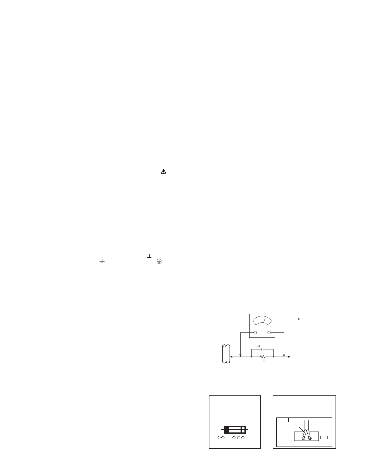
(8) Do not check high voltage by drawing an arc. Use a high voltage
meter or a high voltage probe with a VTVM. Discharge the picture
tube before attempting meter connection, by connecting a clip lead
to the ground frame and connecting the other end of the lead
through a 10k
(9) When service is required, observe the original lead dress. Extra
precaution should be given to assure correct lead dress in the high
voltage circuit area. Where a short circuit has occurred, those
components that indicate evidence of overheating should be
replaced. Always use the manufacturer's replacement components.
Ω 2W resistor to the anode button.
(10) Isolation Check (Safety for Electrical Shock Hazard)
After re-assembling the product, always perform an isolation
check on the exposed metal parts of the cabinet (antenna
terminals, video/audio input and output terminals, Control knobs,
metal cabinet, screwheads, earphone jack, control shafts, etc.) to
be sure the product is safe to operate without danger of electrical
shock.
a) Dielectric Strength Test
The isolation between the AC primary circuit and all metal parts
exposed to the user, particularly any exposed metal part having a
return path to the chassis should withstand a voltage of 1100V AC
(r.m.s.) for a period of one second.
(. . . . Withstand a voltage of 1100V AC (r.m.s.) to an appliance rat-
ed up to 120V, and 3000V AC (r.m.s.) to an appliance rated 200V
or more, for a period of one second.) This method of test requires
test equipment not generally found in the service trade.
b) Leakage Current Check
Plug the AC line cord directly into the AC outlet (do not use a line
isolation transformer during this check.). Using a "Leakage Current
Tester", measure the leakage current from each exposed metal part
of the cabinet, particularly any exposed metal part having a return
path to the chassis, to a known good earth ground (water pipe, etc.).
Any leakage current must not exceed 0.5mA AC (r.m.s.). However,
in tropical area, this must not exceed 0.2mA AC (r.m.s.).
• Alternate Check Method
Plug the AC line cord directly into the AC outlet (do not use a line
isolation transformer during this check.). Use an AC voltmeter
having 1000
ner. Connect a 1500
type capacitor between an exposed metal part and a known
good earth ground (water pipe, etc.). Measure the AC voltage
across the resistor with the AC voltmeter. Move the resistor connection to each exposed metal part, particularly any exposed
metal part having a return path to the chassis, and measure the
AC voltage across the resistor. Now, reverse the plug in the AC
outlet and repeat each measurement. Any voltage measured
must not exceed 0.75V AC (r.m.s.). This corresponds to 0.5mA
AC (r.m.s.).
However, in tropical area, this must not exceed 0.3V AC (r.m.s.).
This corresponds to 0.2mA AC (r.m.s.).
(11) High voltage hold down circuit check.
GOOD EARTH GROUND
After repair of the high voltage hold down circuit, this circuit shall
be checked to operate correctly.See item "How to check the high
voltage hold down circuit".
This mark shows a fast
operating fuse, the
letters indicated below
show the rating.
Ω per volt or more sensitivity in the following man-
Ω 10W resistor paralleled by a 0.15µF AC-
AC VOLTMETER
(HAVING 1000 /V,
OR MORE SENSITIVITY)
0.15 F AC-TYPE
PLACE THIS PROBE
1500 10W
A V
ON EACH EXPOSED
ME TAL PAR T
POWER CORD
REPLACEMENT WARNING.
Connecting the white line side of power
cord to "WHT" character side.
PWB
White line side
WHT
PW
(No.YA455)1-3
Page 4
1.2 INSTALLATION
1.2.1 INSTALLATION SITE
(1) The rear of this set is provided with ventilation openings.
Install the set more than 5 cm from a wall and in a location
with good ventilation.
(2) Avoid the following types of locations.
a) Unstable locations (location must be able to with
stand heavy weight).
b) Locations subjected to direct sunlight.
c) Near stoves or other heating devices.
d) Locations subjected to humidity or oily smoke.
e) Dusty locations.
f) Locations with strong vibration.
1.2.2 INSTALLATION ADJUSTMENT
When installing, moving or changing the orientation of the set,
perform static convergence adjustment according to the
following procedure.
Adjusting CRT color convergence have MANUAL and RESET. It
adjust on the MENU screen.
NOTE :
Please you have TV on for at least 20 minutes before sing this
feature.
This adjustment will be needed only when the colors of the
characters/lines are separated and lack in distinction. If not,
please don't perform the adjustment.
MANUAL
(1) Press the [MENU] key, and select the "CONVERGENCE"
in the Picture Adjust menu with [function up/down] key.
(2) Press the [function left/right] key, the CONVERGENCE
menu appears.
(3) Press the [function up/down] key, and select the
"MANUAL".
(4) Press the [function left/right] key, then CONVERGENCE
adjustment screen appear. [Fig.1]
• If all the crosses are white, no convergence adjustment
is needed.
(5) Select the location you want to adjust by using the [number
(2/4/5/6/8)] keys on the remote control unit. [Fig.2]
(6) Press the [SLEEP TIMER] key to change the color of the
box to the color of the cross you want to adjust (red or
blue).
• You cannot adjust the green cross.
(7) Use the [function up/down] key and the [function left/
right] keys to adjust the position of the cross.
(8) Adjust the three colors crosses until they overlap and
appear as a single white cross.
(9) Press the [OK] key.
(more than 5cm)
Wall
VENTILATION OPENING
NOTE :
• When you adjust the convergence, make sure you
start with the center position (position 5), and work
your way around radial for best results.
• When you make the adjustment in the center
(positions 5), you are making the adjustment for the
whale screen. In other positions, you are making the
adjustment only in that area.
• You can reset the adjustment if you do not like the
results, See below.
(10) Press the [menu] key to end the convergence adjustment
procedure.
RESET
RESET in the CONVERGENCE menu resets all convergence
adjustments to the factory default setting.
Fig.1
2
5
8
64
Fig.2
1-4 (No.YA455)
Page 5
SECTION 2
SPECIFIC SERVICE INSTRUCTIONS
2.1 SYSTEM SETTEING
Be sure to carry out the following operation at the end of
the procedure.
(1) Set to "0 minutes" using the [SLEEP TIMER] key.
(2) While "0 minutes" is displayed, press the [VIDEO
STATUS] key and [DISPLAY] key imultaneously, then
enter the SERVICE MODE.
(3) Press the [4] key (4.Diagnostics) in the SERVICE MENU
SCREEN.
(4) Press the [3] key (3.Self check) in the DIAGNOSTICS
MODE screen.
(5) The SELF CHECK MODE screen is displayed.
(6) Turn off the power by pressing the [POWER] key on the
remote control unit.
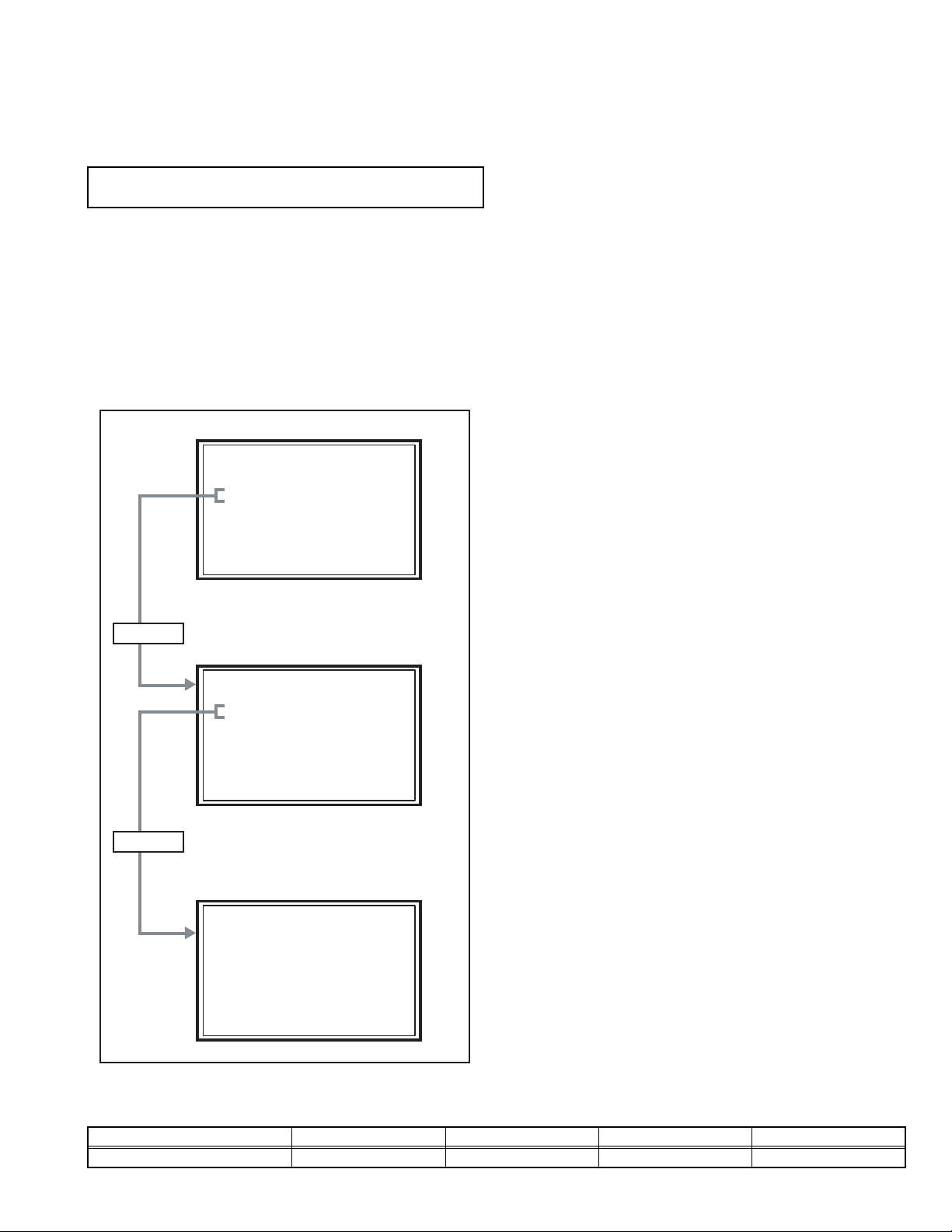
Press [4] key
SERVICE
Service Menu
1.Digital Service
2.TV-Micro Service
3.Conver Service
4.Diagnostics
Diagnostic MENU SCREEN
Diagnostic
1.I2C Bus Stop
2.Status Monitor
3.Self Check
4.Version
5.Save Config data to SD card
6.Load Config data
7.Boot from NFS
8.Debug Log
MENU SCREEN
2.2 FEATURES
Built in ATSC (Advanced Television Systems Committee)
TUNER
This TV can receive both Digital broadcasting (ATSC) and
Analog broadcasting.
SMART CAPTION
Smart caption will appear when you press the MUTING button,
only on channels where the broadcast contains CLOSED
CAPTION information.
SMART SOUND
Decreases high sound levels, giving a regulated sound level.
DIGITAL COMB FILTER
By the 3D digital comb filter, the refreshed image can be seen.
VIDEO STATUS
Expression of a favorite screen can be chosen by the VIDEO
STATUS function.
DIGITAL INPUT
Digital-in will display when any picture signal in Digital-in is
displayed.
V-CHIP
Since the V-CHIP is built in, it can choose, view and listen to a
healthy program.
MTS STEREO
The voice multiplex function of the MTS system is built in.
(MTS = Multi channel Television Sound system)
NATURAL CINEMA
Watching the movie or animation, press the Natural Cinema to
adjust the out line of the images to make thin more sharp.
VIDEO INPUT LABEL
This function is used to label video input connections for the
onscreen displays.
A.H.S.
Adds a more spacious surround sound. Music gives basic
effect and movie for more effect.
Press [3] key
SELF CHECK MODE SCREEN
Self Check 1/2
X-RAY OK
OCP OK
LOB OK
TIM OK
PHOTO OK
HostLink OK
FAN ---
<> Previous/Next Page [BACK]Back [MENU]Exit
2.3 DIFFERENCE LIST
Item AV-48P777/H AV-48P787/H AV-56P777/H AV-56P787/H
BODY COLOR SILVER BLACK SILVER BLACK
(No.YA455)1-5
Page 6
2.4 TECHNICAL INFORMATION
2.4.1 MAIN MICRO COMPUTER (CPU) FUNCTION
Pin
Pin name I/O Function Pin
No.
1 P60/SBT2 - Not used 51 ATSC_TX I Serial communication for ATSC tuner
2 P_MU O Not used : Picture muting [Muting: H] 52 ATSC_RX O Serial communication for ATSC tuner
3 M_MUTE O Audio output muting [Muting: H] 53 P85 - Not used
4 A_MUTE O Audio muting [Muting: H] 54 VREF+ I Reference voltage [+3.3V Fixed]
5 ROTATION_L O
6 ROTATION_R O
7 P52/TM14OA - Not used 57 SDA0 I/O I2C bus (data) for EEPROM
8 P53/TM14OB - Not used 58 SCL0 O I2C bus (clock) for EEPROM
9 DEF_RESET O Not used : Reset for deflection 59 P92/TM10IOB - Not used
10 RD_RQ I DTVM update 60 P93/TM10IOC - Not used
11 POW_LED O
12 DIMMER_LED O
13 P20/SBT2 O Not used : Clock for ATSC tuner communication 63 P95/AN1 - Not used
14 P21/SBI2 I
15 P22/SBO2 O
16 P23 O
17 VDD I +3.3V 67 DIGI_PRO O Not used : HDMI control
18 FOSC O Not used 68 P71/SBI0 - Not used
19 VSS - GND 69 P72/SBO0 - Not used
20 XI I Not used : Low speed oscillator 70 P73 - Not used
21 XO O Not used : Low speed oscillator 71 P74/SBI1 - Not used
22 VDD I +3.3V 72 P75/SBO1 - Not used
23 OSCI I Oscillation for system clock (16MHz) 73 SBD5 I/O On-board writing for flash memory
24 OSCO O Oscillation for system clock (16MHz) 74 SBT5 I On-board writing for flash memory
25 MODE I Single chip mode for CPU [H: Fixed] 75 NMI I +3.3V
26 TU_POWER O Not used : Power control for tuner 76 HDMI_CEC O Not used
27 P25 - Not used 77 REMOCON I Remote control
28 TU_RESET O Reset for tuner [Reset: H] 78 V_SYNC I V. sync signal
29 PANORAMA O Not used : Panorama mode for deflection 79 IRQ3/PA3 - Not used
30 P30/KI0 - Not used 80 POWERGOOD I Not used : Power error detection [NG: H]
31 P31/KI1 - Not used 81 PA5 - Not used
32 P32/KI2 - Not used 82 RST I CPU reset [Reset: L]
33 P33/KI3 - Not used 83 VDD I +3.3V
34 AVDD I +3.3V 84 SCL1 O I2C bus (clock) for RGB & DEF PROCESS (IC301)
35 P34/KI4 - Not used 85 SDA1 I/O I2C bus (data) for RGB & DEF PROCESS (IC301)
36 P35/KI5 - Not used 86 P02 - Not used
37 OCP I B1 over current protect detection [Protection: H] 87 P03 - Not used
38 B1_POWER O B1 relay control [Power on: L] 88 P04 - Not used
39 LOB_PRO I
40 MECA_SW I Machine SW interrupt detection [SW Pushing: L] 90 P06 - Not used
41 MAIN_POW O Main power control [Power on: L] 91 P07 - Not used
42 LB_POWER O Low-B power control [Power on: L] 92 VSS - GND
43 VREF- I Reference voltage [GND Fixed] 93 P10/TM8IOA - Not used
44 X-RAYPRO I X-ray protect detection [Protection: L] 94 P11/TM8IOB - Not used
45 P45/AN5 - Not used 95 P12/TM11IOA - Not used
46 KEY2 I Front key scan voltage (CH+, VOL+/-) 96 P13/TM11IOB - Not used
47 KEY1 I Front key scan voltage (CH-, MENU) 97 P14/TM11IC - Not used
48 P80/TM14OA - Not used 98 P15/TM12IOA - Not used
49 P81/TM14OB - Not used 99 P16/TM12IOB - Not used
50 AC_IN I AC 50/60Hz for timer clock 100 P17/TM12IC - Not used
Not used :
Not used :
Lighting for Power/OnTimer LED [Power ON or TIMER ON: H]
Brightness control for Power/OnTimer LED
Not used : Data receive for ATSC tuner communication
Not used : Data transmission for ATSC tuner communication
Not used : Data request for ATSC tuner communication
Low-B protect detection [Protection: H]
Rotation control (left) 55 CONVER_TX I
Rotation control (right) 56 CONVER_RX O
No.
61 AVSS - GND
62 DIGI_PHOT I Photo sensor for DIGITAL-IN illegal copy protection
64 P96/AN2 - Not used
65 P97/AN3 - Not used
66 VDD I +3.3V
89 P05 - Not used
Pin name I/O Function
Serial communication for convergence control
Serial communication for convergence control
1-6 (No.YA455)
Page 7
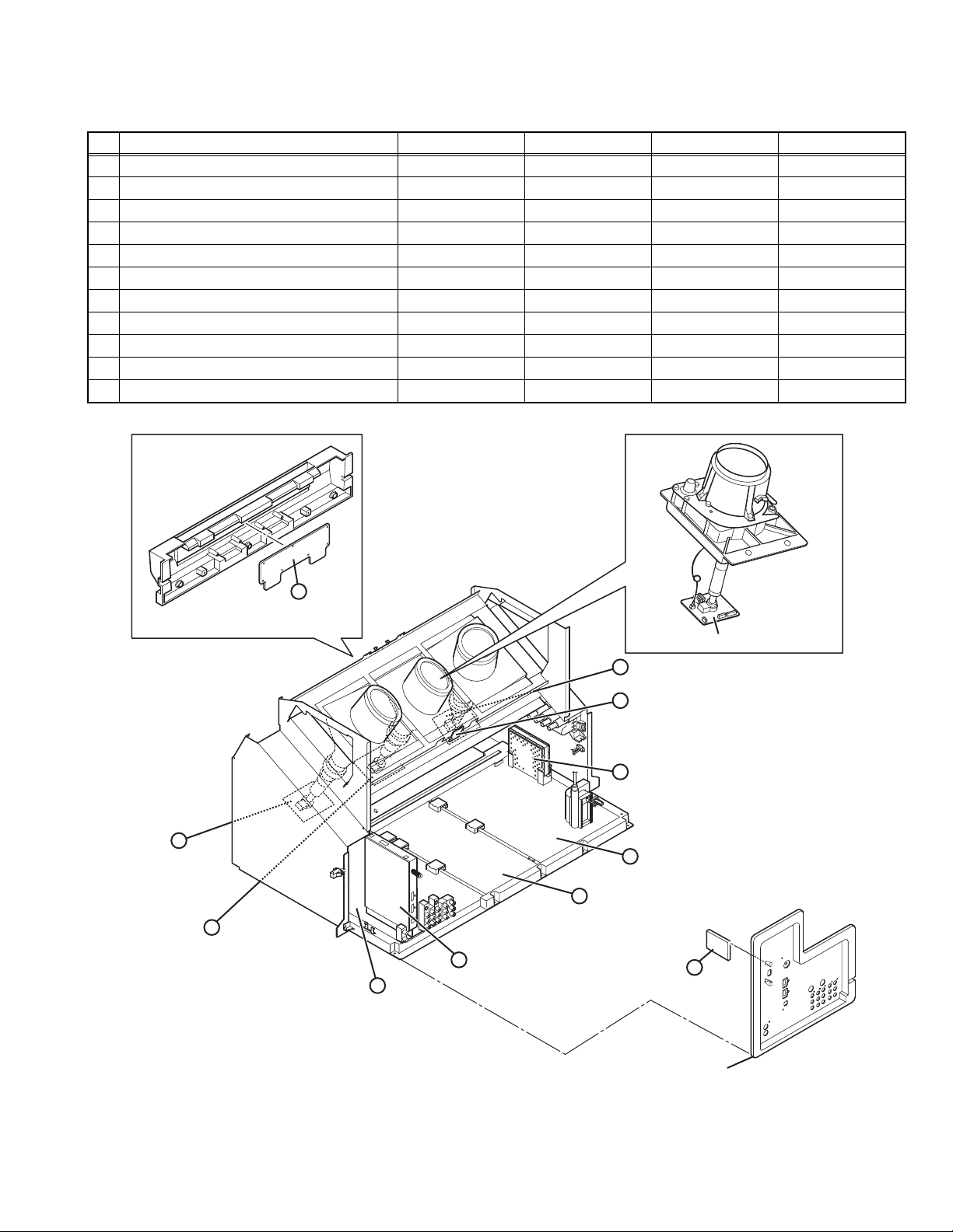
2.5 MAIN PARTS LOCATION
2.5.1 PWB ASS'Y ARRANGEMENT
The PWB ASS'Y is indicated below.
No. PWB ASS'Y name AV-48P776 AV-48P786 AV-56P776 AV-56P786
1. MAIN PWB SSR-1510A-M2 ← SSR-1511A-M2 ←
2. ATSC TUNER PWB SSD-2311A-M2 ←←←
3. POWER PWB SSR-9010A-M2 ←←←
4. DEF & CONVERGENCE OUT PWB SSR-2510A-M2 ←←←
5. DIGITAL CONVERGENCE MODULE PWB SSR0K050A-M2 ← SSR0K051A-M2 ←
6. REMOTE SENSOR PWB SSR-8010A-M2 ←←←
7. R CRT SOCKET PWB SSR-3151A-M2 ←←←
8. G CRT SOCKET PWB SSR-3251A-M2 ←←←
9. B CRT SOCKET PWB SSR-3351A-M2 ←←←
10. FRONT CONTROL PWB SSR0L015A-M2 ←←←
11. USB PWB SSR-7561A-M2 ←←←
FRONT CONTROL ASS'Y
9
B CRT SOCKET
PWB
10
FRONT CONTROL
PWB
7
R CRT SOCKET PWB
6
REMOTE SENSOR PWB
5
DIGITAL CONVERGENCE
MODULE PWB
4
3
POWER PWB
PROJECTION UNIT
G CRT SOCKET PWB
DEF & CONVERGENCE OUT PWB
8
G CRT SOCKET
PWB
1
MAIN PWB
2
ATSC TUNER PWB
USB PWB
11
AV TERMINAL BOARD
(This figure is only MAIN UNIT)
(No.YA455)1-7
Page 8
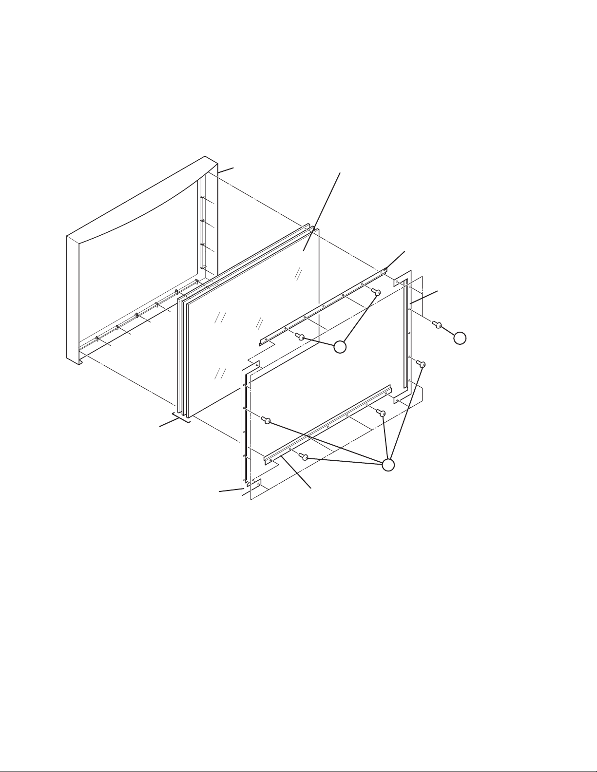
2.6 SCREEN HANDLING CAUTIONS
2.6.1 SCREEN STORAGE
Store the SCREEN ASS'Y in a standing position in order to avoid deformation. If the screen is stored horizontally, there is risk of
deforming the screen face.
When necessary to place the SCREEN ASS'Y horizontally, position the screen side upwards and sure to place spacers between the
screen and resting site (floor or stand etc.) to prevent the screen from sagging.
2.6.2 SCREEN SURFACE
Since the screen surface is easily scratched or soiled, use ample care when handling.
Leave the screen with protector, fresnel lens
and double lenticular lens attached. If cannot
FRONT PANEL
be disassembled further.
SCREEN BRACKET
(TOP)
SCREEN BRACKET
(LEFT)
SCREEN
SCREEN BRACKET
(RIGHT)
A
(x 2)
[56 inch only]
SCREEN BRACKET
(BOTTOM)
A
(x 4)
[56 inch only]
A
(x 14)
1-8 (No.YA455)
Page 9
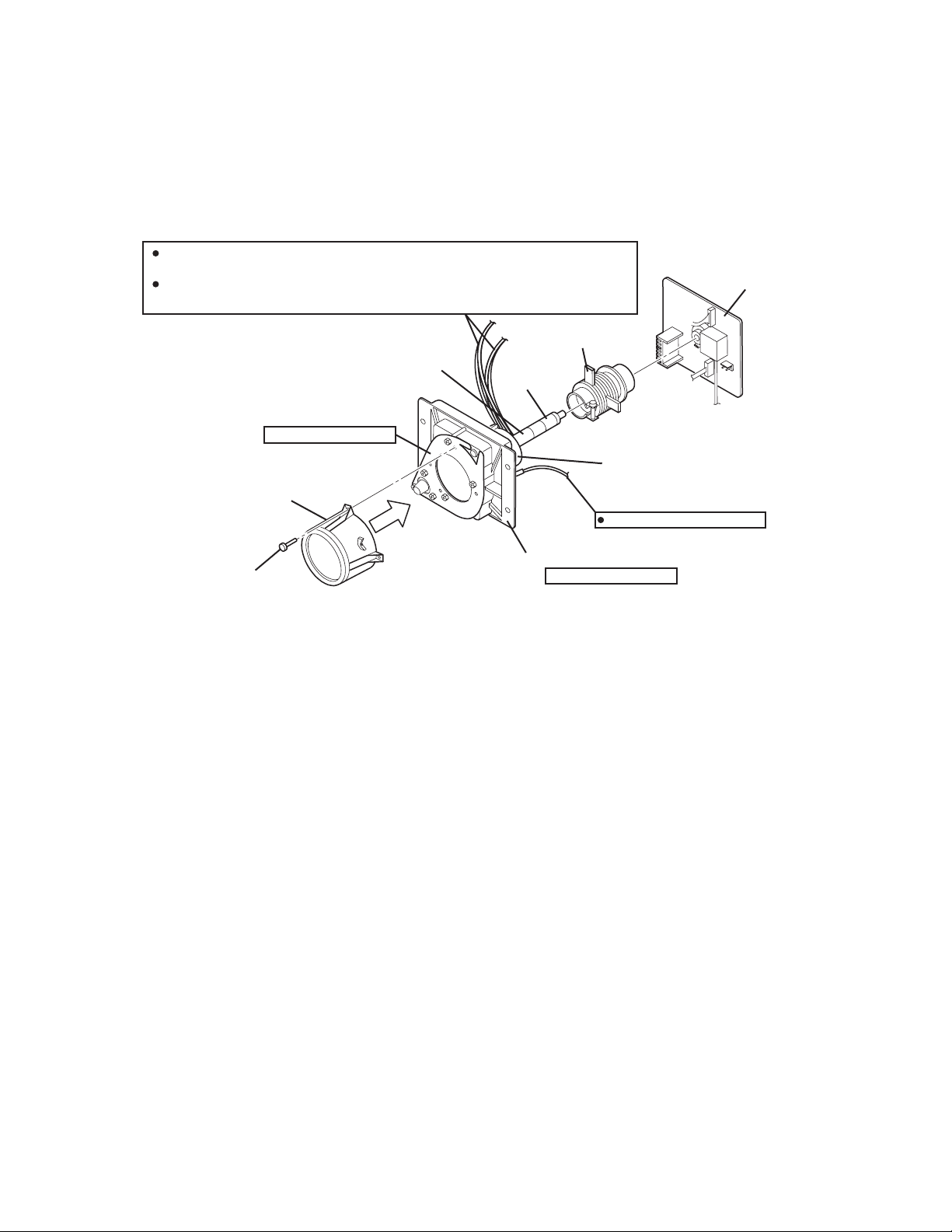
2.7 PROJECTION UNIT REPLACEMENT
2.7.1 ADJUSTMENT DURING REPLACEMENT
When replacing the three R, G and B projection units, first replace the R and B units and perform focus / screen / raster centering
adjustments with reference to the G unit. Then replace the G unit and perform G focus / screen / convergence adjustment. Finally
perform R & B . Convergence adjustments. Use care to simultaneously removes all three-projection units.
2.7.2 DISASSEMBLY CAUTION
The projection units include locations that are not to be disassembled during service. When replacing projection unit parts,
disassemble to the state indicated in the figure below.
The figure indicates screws and wires that are not to be removed. Use care not to remove these.
Deflection yoke wires : to connector on DEF/CONVERGENCE OUT PWB ASS'Y.
[R="RHV", G="GHV", B="BHV"]
Convergence yoke wires : to connector on DEF/CONVERGENCE OUT PWB ASS'Y.
[R="R", G="G", B="B"]
2/4 POLE
Check that tape is applied to the CRT neck.
If absent, the deflection yoke can dislodge.
Do not remove screws
LENS ASS'Y
LENS ASS'Y SCREW ( x 4)
MAGNET
TAPE
CRT ASS'Y (COUPLER ASS'Y)
R CRT SOCKET PWB ASS'Y
G CRT SOCKET PWB ASS'Y
B CRT SOCKET PWB ASS'Y
DEF. / CONVER. YOKE
ANODE wires : to DIVIDER
Do not disassembly
(No.YA455)1-9
Page 10

SECTION 3
DISASSEMBLY
3.1 DISASSEMBLY PROCEDURE
CAUTION AT DISASSEMBLY:
• Be sure to perform the SYSTEM SETTEING, at the end of the procedure.
• Make sure that the power cord is disconnected from the outlet.
• Pay special attention not to break or damage the parts.
• When removing each board, remove the connectors as required. Taking notes of the connecting points (connector numbers)
makes service procedure manageable.
• Make sure that there is no bent or stain on the connectors before inserting, and firmly insert the connectors.
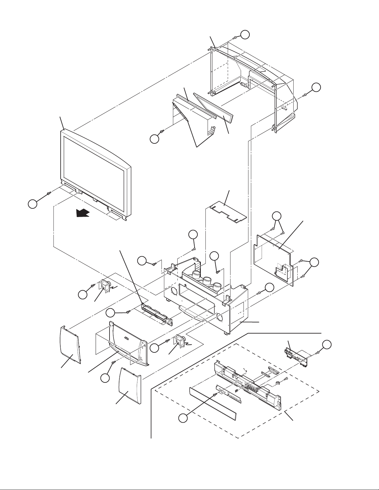
3.1.1 REMOVING THE SPEAKER GRILL (Fig.1)
(1) Remove 2 screws [A] from rear side.
(2) Pull out the SPEAKER GRILL bottom to the front, and 4
claws which are fixing the SPEAKER GRILL are removed.
(3) Remove the SPEAKER GRILL.
(4) Remove the other side SPEAKER GRILL in the same
manner.
3.1.2 REMOVING THE SPEAKER (Fig.1)
• Remove the SPEAKER GRILL.
(1) Remove 4 screws [B].
(2) Remove the SPEAKER.
(3) Disconnect the speaker wire from speaker terminal.
(4) Remove the other side SPEAKER in the same manner.
3.1.3 REMOVING THE FRONT PANEL (Fig.1)
• Remove the SPEAKER GRILL.
(1) Remove 4 screws [C].
(2) The FRONT PANEL upper is pull out to the front, and 2
claws which are fixing the FRONT PANEL are removed.
(3) Remove the FRONT PANEL.
3.1.4 REMOVING THE FRONT CONTROL BOX (Fig.1)
• Remove the SPEAKER GRILL.
• Remove the FRONT PANEL.
(1) Remove 5 screws [D].
(2) Remove the FRONT CONTROL BOX.
3.1.5 REMOVING THE FRONT CONTROL PWB (Fig.1)
• Remove the SPEAKER GRILL.
• Remove the FRONT PANEL.
• Remove the FRONT CONTROL BOX.
(1) Remove 2 screws [E].
(2) Remove 3 screws [F] from rear side of FRONT CONTROL
BOX.
(3) Remove the FRONT CONTROL PWB.
3.1.6 REMOVING THE SCREEN ASS'Y (Fig.1)
• Remove the SPEAKER GRILL.
• Remove the FRONT PANEL.
• Remove the FRONT CONTROL BOX.
(1) Remove 4 screws [G] attaching the SCREEN ASS'Y.
(2) Remove 10 screws [H] from rear side.
(3) Remove the SCREEN ASS'Y.
NOTE :
• Please place the SCREEN ASS'Y on a flat table without fail.
• Because of the large size, at least 2 persons are
recommended for removal and reassemble.
• Use care not to scratch the screen during work.
• During assembly, be sure to engage the left and right tabs
with the cabinet mounting positions.
• When than supporting the SCREEN ASS'Y, avoid grasping
the top of the screen panel, instead grasp the left and right
areas.
3.1.7 REMOVING THE MIRROR (Fig.1)
• Remove the SPEAKER GRILL
• Remove the FRONT PANEL.
• Remove the FRONT CONTROL BOX.
• Remove the SCREEN ASS'Y.
(1) Remove 9 screws [J] attaching the mirror brackets of the
upper, left and right side.
(2) Raise slightly to disengage of the mirror from the bottom
bracket. (If necessary, loosen the screws attaching the
bottom bracket)
(3) Remove the MIRROR.
NOTE :
• The MIRROR is front coated. Do not touch the front of the
MIRROR.
• At least 2 persons are recommended for removable and
reassemble.
1-10 (No.YA455)
Page 11

3.1.8 REMOVING THE REAR COVER (Fig.1)
• Remove the SPEAKER GRILL.
• Remove the FRONT PANEL.
• Remove the FRONT CONTROL BOX.
• Remove the SCREEN ASS'Y.
(1) Remove 2 screws [K].
(2) Remove 2 screws [L] from front side.
(3) Slightly pull for backside to disengage of the REAR
COVER from hooks.
(4) Remove the REAR COVER.
NOTE :
• Because of the large size, at least 2 persons are
recommended for removal and reassemble.
3.1.9 REMOVING THE REAR PANEL (Fig.1)
(1) Remove 12 screws [M].
(2) Remove the REAR PANEL.
3.1.10 REMOVING THE PARTITION (Fig.1)
• Remove the REAR PANEL.
(1) Pull out the PARTITION backward.
(No.YA455)1-11
Page 12
SCREEN
ASS’Y
REAR COVER
MIRROR
BRACKET
H
K
J
MIRROR
MIRROR
BRACKET
PARTITION
G
FRONT
M
REAR PANEL
A
FRONT CONTROL
BOX
L
L
M
A
B
SPEAKER
D
BODY
SPEAKER
GRILLE
1-12 (No.YA455)
FRONT
PANEL
C
SPEAKER
GRILLE
B
SPEAKER
FRONT CONTROL PWB
F
E
FRONT CONTROL
BOX
Fig.1
Page 13

3.1.11 REMOVING THE MAIN UNIT (Fig.3)
• Remove the SPEAKER GRILL.
• Remove the FRONT PANEL.
• Remove the FRONTCONTROL BOX.
• Remove the REAR PANEL.
(1) Remove 4 screws [N] from front side of both sides.
(2) Remove 2 screws [P] attaching the MAIN CHASSIS and
BODY.
(3) Remove the SPEAKER CONNECTOR.
(4) Pull out the MAIN UNIT to rear side.
NOTE :
• Except for confirmation of projection of images on the screen
and audio output through the speakers, the removed MAIN
UNIT is still workable in the same state as if it is still built-in
the TV set. Therefore, the MAIN UNIT can be removed, if
necessary, for board diagnosis, electric testing, etc. apart
from confirmation of screen images and audio output.
• When wire clamps are removed during work, use care to
restore them precisely to their original positions.
Performance can be affected if these are not returned to the
original positions.
• Because of the large size, at least 2 persons are
recommended for removal and reassemble.
• When carrying the MAIN UNIT, use care not to drop, shock
or shake it.
• Do not stain or damage the lens of the PROJECTION UNIT.
• Do not look the projection side of a PROJECTION UNIT
when the image is projected.
3.1.11.1 CHECKING THE P.W. BOARD (Fig.2)
When checking the MAIN PWB, POWER PWB, DEF &
CONVERGENCE OUT PWB, etc., raise the MAIN UNIT with the
front side down for the make of convenience.
3.1.12 REMOVING THE FOCUS PACK (Fig.2)
• Remove the SPEAKER GRILL.
• Remove the FRONT PANEL.
• Remove the FRONTCONTROL BOX.
• Remove the REAR PANEL.
• Remove the MAIN UNIT.
(1) Remove 1 screw [Q].
(2) Remove the FOCUS PACK.
(3) Remove wires connecting the FOCUS PACK.
3.1.14 REMOVING THE MAIN CHASSIS (Fig.2)
• Remove the REAR PANEL.
(1) Remove 2 screws [V].
(2) Pull out the MAIN CHASSIS for backside.
NOTE :
• If necessary, remove the anode wires, connectors,
respectively.
3.1.15 REMOVING THE ATSC TUNER PWB (Fig.2)
• Remove the REAR PANEL.
• Remove the AV TERMINAL BOARD.
• Remove the MAIN CHASSIS.
(1) Remove 1 screw [W].
(2) Pull out the ATSC TUNER PWB.
3.1.16 REMOVING THE DIGITAL CONVERGENCE MODULE
PWB (Fig.2)
• Remove the REAR PANEL.
• Remove the MAIN CHASSIS.
(1) Remove 2 screws [X].
(2) Pull out the DIGITAL CONVERGENCE MODULE PWB.
3.1.17 REMOVING THE DEF & CONVERGENCE OUT PWB
(Fig.2)
• Remove the REAR PANEL.
• Remove the MAIN CHASSIS.
(1) Remove 1 screw [Y].
(2) Remove the DEF & CONVERGENCE OUT PWB.
3.1.18 REMOVING THE POWER PWB (Fig.2)
• Remove the REAR PANEL.
• Remove the MAIN CHASSIS.
(1) Remove 1 screw [Z].
(2) Remove the POWER PWB.
3.1.13 REMOVING THE AV TERMINAL BOARD (Fig.2)
• Remove the REAR PANEL.
(1) Remove 6 screws [R], 2 screws [S] and 2 screws [T].
(2) Pull out the POWER CORD CLAMP from AV TERMINAL
BOARD to right side.
(3) Remove the AV TERMINAL BOARD.
3.1.13.1 REMOVING THE USB PWB (Fig.2)
• Remove the REAR PANEL.
• Remove the AV TERMINAL BOARD.
(1) Remove 2 screws [U].
(2) Remove the USB PWB.
(No.YA455)1-13
Page 14

3.1.19 REMOVING THE PROJECTION UNIT (Fig.2)
• Remove the SPEAKER GRILL.
• Remove the FRONT PANEL.
• Remove the FRONT CONTROL BOX.
• Remove the REAR PANEL.
• Remove the MAIN UNIT.
(1) Remove the CRT SOCKET PWB.
(2) Remove 4 screws [a].
(3) Pull out the PROJECTION UNIT upward.
NOTE :
• Refer to "PROJECTION UNIT REPLACEMENT" when tak-
ing out and replacing the PROJECTION UNIT.
• When wire clamps are removed during work, use care to re-
store them precisely to their original positions. Performance
can be affected if these are not returned to the original positions.
3.1.20 REMOVING THE HV DIVIDER (Fig.2)
• Remove the REAR PANEL.
(1) Remove 1 screw [b].
(2) Remove the HV DIVIDER.
NOTE :
• Wires of the transformer (FBT) and CRT of each PROJECTION UNIT can be removed by turning the connector portions.
• If necessary, remove the anode wires, and replacing the HV
DIVIDER, take care to correctly engage the connector.
3.1.21 REMOVING THE REMOTE SENSOR PWB (Fig.2)
• Remove the REAR PANEL.
(1) Remove 1 screw [c].
(2) Remove the REMOTE SENSOR PWB.
3.1.22 REMOVING THE COOLANT PAN (Fig.2)
• Remove the REAR PANEL.
(1) Remove 2 screws [d].
(2) Remove the COOLANT PAN.
1-14 (No.YA455)
Page 15

a
MAIN UNIT
BODY
PROJECTION
UNIT
FOCUS PACK
MAIN UNIT
FRONT
Q
COOLANT PAN
REMOTE
SOENSOR
PWB
d
SPEAKER
N
FRONT
CONNECTOR
REAR SIDE VIEW
MAIN UNIT
BODY
MAIN
CHASSIS
FRONT
HV
P
Fig.3
DIVIDER
c
X
DIGITAL CONVERGENCE
MODULE PWB
b
Y
Z
ATSC TUNER PWB
MAIN PWB
W
POWER PWB
V
Fig.2
U
USB PWB
AV TERMINAL
BOARD
DEF & CONVERGENCE
OUT PWB
MAIN CHASSIS
V
POWER CORD
CLAMP
POWER CORD
R
S
T
(No.YA455)1-15
Page 16

3.2 MEMORY IC REPLACEMENT
• This model uses the memory IC.
• This memory IC stores data for proper operation of the video and drive circuits.
• When replacing, be sure to use an IC containing this (initial value) data.
3.2.1 MEMORY IC TABLE
Simbol Number of pins Mounting PWB Main content of data
IC702
3.2.2 MEMORY IC REPLACEMENT PROCEDURE
1. Power off
Switch off the power and disconnect the power plug.
2. Replace the memory IC
Be sure to use a memory IC written with the initial setting data.
3. Power on
Connect the power cord to the wall outlet and switch on the
power.
4. Receiving channel setting
Refer to the OPERATING INSTRUCTIONS (USER'S GUIDE)
and set the receive channels (Channels Preset) as described.
5. User settings
Check the user setting items according to the "FACTORY
SETTING ITEM" table.
Where these do not agree, refer to the OPERATING
INSTRUCTIONS (USER'S GUIDE) and set the items as
described.
6. SERVICE MODE setting
Verify what to set in the SERVICE MODE, and set whatever is
necessary(Fig.1) .
Refer to the SERVICE ADJUSTMENT for setting.
8-pin MAIN PWB Setting value of Initial setting data is memorized.
1-16 (No.YA455)
Page 17

3.2.3 SERVICE MODE SETTING ITEMS
Service Menu
Service Menu
1.Digital Service
2.TV-Micro Service
3.Conver Service
4.Diagnostics
Digital Service
Digital Service
1.Adjust
2.Memory Edit
3.Edit Config
4.All Reset
5.Select Channel Map
6.Clear Channel Map
7.Digital Tunig Test
Press [2] key
TV-Micro Service
Press [1] key
Setting items Settings Item No.
1. Digital Service
Audio system setting Adjust A001 - A010
2. TV-Micro Service
Video system setting Adjust S001 - S060
Deflection system Adjust D001 - D071
Factory system setting Fixed F001
3. Conver Service
Adjust CPA01 - CPA11
Adjust CCA01 - CCA12
Fixed CDA01 - CDA07
Fixed CBA01 - CBA111
Press [3] key
TV-Micro Service
1.Adjust
2.White Balance
3.Memory Edit
Conver Service
Conver Service
1.Coarse Adjust
2.Fine Adjust
3.Conver Off
Fig.1
(No.YA455)1-17
Page 18

3.2.4 SETTINGS OF FACTORY SHIPMENT
3.2.4.1 BUTTON OPERATION 3.2.4.2 REMOTE CONTROL DIRECT OPERATION
Setting item Setting position
POWER Off
CHANNEL CABLE-02
VOLUME 10
3.2.4.3 REMOTE CONTROL MENU OPERATION
INPUT TV
CHANNEL CABLE-02
VOLUME 10
MUTING OFF
DISPLAY OFF
SLEEP TIMER OFF
VIDEO STATUS DYNAMIC
THEATER PRO OFF
C.C. OFF
MTS STEREO
ASPECT PANORAMA
SOUND
Setting item Setting position
A.H.S. OFF
Smart Sound OFF
(1) INITIAL SETUP
Setting item Setting position
Noise Muting On
Language English
Front Panel Lock Off
V-Chip Off
Set Lock Code 0000
Closed Caption Auto(CC1/T1)
Auto Shut Off Off
Power Indicator High
(2) TUNER SETUP
Setting item Setting position
Auto Tuner Setup Unnecessary to set
(6) PICTURE ADJUST
Customers can adjust the picture setting of menu screen as their own like but the picture standard value during factory shipment is as below.
Setting item TINT COLOR PICTURE BRIGHT DETAIL
STANDARD 00000LOWOFFOFF
DINAMIC 00+60+10HIGHOFFOFF
THEATER -3 -3 -10 +1 0 HIGH OFF OFF
GAME 0+7-100+7LOWOFFOFF
(3) SOUND ADJUST
Setting item Setting position
Bass 0
Treble 0
Balance 0
Optical Out PCM
Turn On Volume Current
Volume Limit 50
(4) CLOCK / TIMERS
Setting item Setting position
Set Clock Manual
On / Off Timer Off
(5) EXTERNAL INPUT
Setting item Setting position
Digital-In Size Auto
Digital-In1 Audio Auto
Video Input Label All blank
COLOR
TEMPERATURE
REDUCTION
NOISE
NATURAL
CINEMA
1-18 (No.YA455)
Page 19

3.3 REPLACEMENT OF CHIP COMPONENT
3.3.1 CAUTIONS
(1) Avoid heating for more than 3 seconds.
(2) Do not rub the electrodes and the resist parts of the pattern.
(3) When removing a chip part, melt the solder adequately.
(4) Do not reuse a chip part after removing it.
3.3.2 SOLDERING IRON
(1) Use a high insulation soldering iron with a thin pointed end of it.
(2) A 30w soldering iron is recommended for easily removing parts.
3.3.3 REPLACEMENT STEPS
1. How to remove Chip parts
2. How to install Chip parts
[Resistors, capacitors, etc.]
(1) As shown in the figure, push the part with tweezers and
alternately melt the solder at each end.
(2) Shift with the tweezers and remove the chip part.
[Transistors, diodes, variable resistors, etc.]
(1) Apply extra solder to each lead.
SOLDER
SOLDER
[Resistors, capacitors, etc.]
(1) Apply solder to the pattern as indicated in the figure.
(2) Grasp the chip part with tweezers and place it on the
solder. Then heat and melt the solder at both ends of the
chip part.
[Transistors, diodes, variable resistors, etc.]
(1) Apply solder to the pattern as indicated in the figure.
(2) Grasp the chip part with tweezers and place it on the
solder.
(3) First solder lead A as indicated in the figure.
(2) As shown in the figure, push the part with tweezers and
alternately melt the solder at each lead. Shift and remove
the chip part.
Note :
After removing the part, remove remaining solder from the
pattern.
A
B
C
(4) Then solder leads B and C.
A
B
C
(No.YA455)1-19
Page 20

SECTION 4
ADJUSTMENT
4.1 ADJUSTMENT PREPARATION
(1) You can make the necessary adjustments for this unit with
either the Remote Control Unit or with the adjustment tools
and parts as given below.
(2) Adjustment with the Remote Control Unit is made on the
basis of the initial setting values, however, the new setting
values which set the screen to its optimum condition may
differ from the initial settings.
(3) Make sure that AC power is turned on correctly.
(4) Turn on the power for set and test equipment before use,
and start the adjustment procedures after waiting at least
30 minutes.
(5) Unless otherwise specified, prepare the most suitable
reception or input signal for adjustment.
(6) Never touch any adjustment setting value which are not
specified in the list for this adjustment.
(7) Presetting before adjustment
Unless otherwise specified in the adjustment instructions,
preset the following functions with the remote control unit.
4.2 MEASURING INSTRUMENT AND FIXTURES
(1) DC voltmeter (or digital voltmeter)
(2) Oscilloscope
(3) Signal generator (Pattern generator)
[NTSC]
(4) TV audio multiplex signal generator
(5) Remote control unit
(6) Jig Remote Control Unit [Parts number : LP20873-009A]
NOTE:
Please order to your parts center if you do not have this remote control unit.
SETTING POSITION
Setting item Setting position
VIDEO STATUS STANDARD
TINT / COLOR / PICTURE /
BRIGHT / DETAIL
00 (Center)
COLOR TEMPERATURE LOW
NOISE REDUCTION OFF
NATURAL CINEMA AUTO
BASS / TREBLE / BALANCE 00 (Center)
ASPECT FULL
VERTICAL POSITION Center
ON/OFF TIMER OFF
AUTO SHUT OFF OFF
4.3 ADJUSTMENT FLOWCHART
WHEN REPLACING SCREEN AND PROJECTION UNIT
• Contains only the main adjustments. Also confirm other adjustments as required.
1 Projection unit
Install projection tube
LENS FOCUS
BEAM SPOT
CRT FOCUS
SCREEN & LOW LIGHT
DEFLECTION
CONVERGENCE
(match to unreplaced tube)
HIGH LIGHT
END
3 Projection unit
Install projection tube
LENS FOCUS
BEAM SPOT
CRT FOCUS
SCREEN & LOW LIGHT
DEFLECTION
G CONVERGENCE
R CONVERGENCE
B CONVERGENCE
HIGH LIGHT
END
SCREEN
LENS FOCUS
G convergence
disturbed
Y
G CONVERGENCE
R CONVERGENCE
B CONVERGENCE
END
N
1-20 (No.YA455)
Page 21

4.4 BASIC OPERATION OF SERVICE MENU
TVM Memory Edit
Addr (H) 00
0 1 2 3 4 5 6 7
04 01 06 58 FF FF FF FF
8 9 A B C D E F
11 29 00 00 01 FF FD FD
Digital Memory Edit
Addr (H) 0000
0 1 2 3 4 5 6 7
04 01 06 58 FF FF FF FF
8 9 A B C D E F
11 29 00 00 01 FF FD FD
SERVICE MENU
Service Menu
1.Digital Service
1. Digital Service
Digital Service
1.Adjust
2.Memory Edit
3.Edit Config
4.All Reset
5.Select Channel Map
6.Clear Channel Map
7.Digital Tunig Test
A001- A010
1.Adjust
A001 IN LAVEL 6
NTSC 43Full Dynamic H
2.TV-Micro Service
3.Conver Service
4.Diagnostics
1. Adjust
S001 BRIGHT 054
NTSC 43Full DYN H
2. TV-Micro Service
TV-Micro Service
1.Adjust
2.White Balance
3.Memory Edit
4.Diagnostics
[Refer to SECTION 5]
3. Conver Service
Conver Service
1.Coarse Adjust
2.Fine Adjust
3.Conver Off
1. Coarse Adjust
CPA01 FINE OFF 0
2. Memory Edit
Digital Memory Edit
Addr (H) 0000
0 1 2 3 4 5 6 7
04 01 06 58 FF FF FF FF
8 9 A B C D E F
11 29 00 00 01 FF FD FD
3. Edit Config
4. All Reset
5. Select Channel Map
DO NOT ADJUST
D001 - D071
2. White Balance
BR 054
DRV R031 B031
CUT R031 G031 B031
3. Memory Edit
S001- S060
S001 BRIGHT 054
NTSC 43Full DYN H
D001 V.SIZE 022
NTSC 43Full DYN H
F001
F001 DTVM RST 001
NTSC 43Full DYN H
TVM Memory Edit
Addr (H) 00
0 1 2 3 4 5 6 7
04 01 06 58 FF FF FF FF
8 9 A B C D E F
11 29 00 00 01 FF FD FD
CPA01 - CPA11
CPA01 FINE OFF 0
CCA01 - CCA12
CCA01 C H CENT 0
DO NOT ADJUST
CDA01 - CDA07
CDA01 DF DC 0
CBA01 - CBA111
CBA01 ADD RATIO 0
2. Fine Adjust
3. Conver Off
6. Clear Channel Map
7. Digital Tunig Test
(No.YA455)1-21
Page 22

4.5 SERVICE MODE
Service Menu
1.Digital Service
2.T
-Micro Servic
3.Co
er Servic
4.Diagnostics
4.5.1 BASIC OPERATION OF SERVICE MODE
Operate the SERVICE MODE with the REMOTE CONTROL UNIT.
4.5.1.1 HOW TO ENTER THE SERVICE MODE
(1) Set to "0 minutes" using the [SLEEP TIMER] key.
(2) While "0 minutes" is displayed, press the [VIDEO
STATUS] key and [DISPLAY] key simultaneously.
(3) Enter the SERVICE MODE (Fig.1)
SERVICE MENU SCREEN
Service Menu
1.Digital Service
2.T
V-Micro Servic
3.Co
nver Servic
4.Diagnostics
4.5.1.2 HOW TO EXIT THE SERVICE MODE
Press the [ MENU ] key to exit the SERVICE MODE.
4.5.1.3 HOW TO STORE OF SETTING VALUE
When adjustment is completed, press the [MUTING] key to
memorize the adjustment value.
NOTE:
If not to do it, adjustment data is not memorized to the memory
IC. And if exit the adjustment mode before memorize the data,
the adjustment value which you change is canceled.
e
e
Fig.1
4.5.1.4 SERVICE MODE SELECT KEY LOCATION
TV/CATV
switch
DISPLAY
SLEEP
TIMER
VIDEO
STATUS
MUTING
VOL -
MENU
TV
CATV VCR
SLEEP
TIMER
THEATER PRO
VIDEO STATUS
ASPECT
SUB CH
FAVORITE
MUTING
VOL
–
MENU
VCR CHANNEL
PREV NEXT
REC
OPEN/CLOSE
POWER
DVD
DISPLAY C.C.
1
2
4
5
7
8
TUNE
0
ML/MTS SOUND GUIDE
CH +
CH –
VCR/DVD
POWER
PLAY FFREW
STOP PAUSE
STILL/PAUSE
RM-C1272G
TV
INPUT
RETURN+
VOL
BACK
TV/VCR
VCR/DVD
switch
POWER
3
NUMBER
6
9
/TV
CH +
OK
VOL +
+
BACK
CH -
1-22 (No.YA455)
Page 23

4.5.2 DESCRIPTION OF STATUS DISPLAY
Digital Memory Edit
Addr (H) 0000
0 1 2 3 4 5 6 7
04 01 06 58 FF FF FF FF
8 9 A B C D E F
11 29 00 00 01 FF FD FD
The status display on the upper part of the SERVICE MODE screen is common (to all models).
4.5.2.1 DIGITAL SERVICE MODE
1. Adjust
(4) WHITE BALANCE
State of the WHITE BALANCE is displayed.
SETTING ITEM No.
A001 IN LEVEL 6
NTSC 43Full Dynamic H
SETTING ITEM
SETTING VALUE (DATA)
H: HIGH
L: LOW
(5) SETTING ITEM NAME
Setting item name are displayed. For the setting item names
to be displayed, refer to "INITIAL SETTING VALUE OF
SERVICE MODE".
(6) SETTING ITEM NO.
Setting item numbers are displayed. The setting item numbers
SIGNAL SYSTEM
SCREEN MODE
VIDEO STATUS
WHITE BALANCE
to be displayed are listed below.
Item No. Setting item
(1) SIGNAL SYSTEM
The signal displayed on the screen is displayed.
NTSC : 525i (Composite / S-video input)
525i : 525i (Component input)
525p : 525p (Component input)
750p : 750p (Component input)
A001 - A010 Audio system setting
SELECTION OF SETTING ITEM
• [CH+] / [CH-] key.
Change the setting items up/ down.
A001... ↔ A010
1125i : 1125i (Component input)
D525i : ATSC 525i
D525p : ATSC 525p
D750p : ATSC 750p
D1125i : ATSC 1125i
H525i : HDMI 525i
(7) SETTING VALUE (DATA)
The SETTING VALUE is displayed.
CHANGE OF SETTING VALUE (DATA)
• [VOL+] / [VOL-] key.
Change the setting values up/down.
H525pS1 : HDMI 525p size1
H525pS2 : HDMI 525p size2
H750p : HDMI 750p
H1125i : HDMI 1125i
MEMORY OF SETTING VALUE (DATA)
Changed setting value is memorized by pressing
[MUTING] key.
2. Memory Edit
(2) SCREEN MODE
State of the ASPECT is displayed.
43Full : FULL (Input signal 4 : 3)
43Pano : PANORAMA (Input signal 4 : 3)
Data in the EEPROM is edited on this screen. [Do not adjust]
CAUTION:
This mode is not used in the ADJUSTMENT. Press the
[BACK] key to return to the SERVICE MENU SCREEN.
43Cinema : CINEMA (Input signal 4 : 3)
43Regular : REGULAR (Input signal 4 : 3)
MEMORY EDIT MODE
16Full : FULL (Input signal 16 : 9)
16Pano : PANORAMA ZOOM (Input signal 16 : 9)
16Cinema : CINEMA ZOOM (Input signal 16 : 9)
16Slim : SLIM (Input signal 16 : 9)
Digital Memory Edit
Addr (H) 0000
0 1 2 3 4 5 6 7
04 01 06 58 FF FF FF FF
8 9 A B C D E F
11 29 00 00 01 FF FD FD
(3) VIDEO STATUS
State of the VIDEO STATUS is displayed.
Standard : STANDARD
Dynamic : DYNAMIC
Theater : THEATER
Game : GAME
(No.YA455)1-23
Page 24

3. Edit Config
Setting value in the digital module is edited and confirmed on
this screen. [Do not adjust]
CAUTION:
This mode is not used in the ADJUSTMENT. Press the
[BACK] key to return to the SERVICE MENU SCREEN.
6. Clear Channel Map
Channel map is cleared on this screen. [Do not adjust]
CAUTION:
This mode is not used in the ADJUSTMENT. Press the
[BACK] key to return to the SERVICE MENU SCREEN.
EDIT CONFIG MODE
4. All Reset
Data in the EEPROM is all reset on this screen. [Do not adjust]
CAUTION:
This mode is not used in the ADJUSTMENT. Press the
[BACK] key to return to the SERVICE MENU SCREEN.
ALL RESET MODE
CLEAR CHANNEL MAP MODE
7. Digital Tuning Test
Digital channel tuning is tested on this screen. [Do not adjust]
CAUTION:
This mode is not used in the ADJUSTMENT. Press the
[BACK] key to return to the SERVICE MENU SCREEN.
DIGITAL TUNING TEST MODE
5. Select Channel Map
Channel map is forcibly rewritten on this screen.[Do not adjust]
CAUTION:
This mode is not used in the ADJUSTMENT. Press the
[BACK] key to return to the SERVICE MENU SCREEN.
SELECT CHANNEL MAP MODE
1-24 (No.YA455)
Page 25

4.5.2.2 TV-MICRO SERVICE MODE
1. Adjust
SETTING ITEM No.
SETTING ITEM
SETTING VALUE (DATA)
(5) SETTING ITEM NAME
Setting item name are displayed. For the setting item names
to be displayed, refer to "INITIAL SETTING VALUE OF
SERVICE MODE".
S001 BRIGHT 064
NTSC 43Full DYN H
SIGNAL SYSTEM
SCREEN MODE
VIDEO STATUS
(1) SIGNAL SYSTEM
The signal displayed on the screen is displayed.
NTSC : 525i (Composite / S-video input)
525i : 525i (Component input)
525p : 525p (Component input)
750p : 750p (Component input)
1125i : 1125i (Component input)
D525i : ATSC 525i
D525p : ATSC 525p
D750p : ATSC 750p
D1125i : ATSC 1125i
H525i : HDMI 525i
H525pS1 : HDMI 525p size1
H525pS2 : HDMI 525p size2
H750p : HDMI 750p
H1125i : HDMI 1125i
WHITE BALANCE
(6) SETTING ITEM NO.
Setting item numbers are displayed. The setting item numbers
to be displayed are listed below.
Item No. Setting item
S001 - S060 Video system setting
D001 - D071 Deflection system
F001 Factory system setting
SELECTION OF SETTING ITEM
• [CH+] / [CH-] key.
Change the setting items up/ down.
S001... ↔ D001... ↔ F001...↔ S001...
• [SLEEP TIMER] key.
Switch to the next items.
S001 → D001 → F001 → S001
(7) SETTING VALUE (DATA)
The SETTING VALUE is displayed.
CHANGE OF SETTING VALUE (DATA)
• [VOL+] / [VOL-] key.
Change the setting values up/down.
MEMORY OF SETTING VALUE (DATA)
Changed setting value is memorized by pressing
[MUTING] key.
(2) SCREEN MODE
State of the ASPECT is displayed.
43Full : FULL (Input signal 4 : 3)
43Pano : PANORAMA (Input signal 4 : 3)
43Cinema : CINEMA (Input signal 4 : 3)
43Regular : REGULAR (Input signal 4 : 3)
16Full : FULL (Input signal 16 : 9)
16Pano : PANORAMA ZOOM (Input signal 16 : 9)
16Cinema : CINEMA ZOOM (Input signal 16 : 9)
16Slim : SLIM (Input signal 16 : 9)
(3) VIDEO STATUS
State of the VIDEO STATUS is displayed.
STD : STANDARD
DYN : DYNAMIC
THEA : THEATER
GAME : GAME
(4) WHITE BALANCE
State of the WHITE BALANCE is displayed.
H: HIGH
L: LOW
(No.YA455)1-25
Page 26

2. White Balance
TVM Memory Edit
Addr (H) 00
0 1 2 3 4 5 6 7
04 01 06 58 FF FF FF FF
8 9 A B C D E F
11 29 00 00 01 FF FD FD
White balance data is adjusted on this screen.
SETTING VALUE (DATA)
BRIGHTNESS
DRIVE
CUTOFF
BR 054
DRV R031 B031
CUT R031 G031 B031
BRIGHTNESS
[VOL+] key : BRIGHT is up
[VOL-] key : BRIGHT is down
DRIVE
[2] key : DRIVE R is up
[5] key : DRIVE R is down
[3] key : DRIVE B is up
[6] key : DRIVE B is down
3. Memory Edit
Data in the EEPROM is edited on this screen. [Do not adjust]
CAUTION:
This mode is not used in the ADJUSTMENT. Press the
[BACK] key to return to the SERVICE MENU SCREEN.
MEMORY EDIT MODE
TVM Memory Edit
Addr (H) 00
0 1 2 3 4 5 6 7
04 01 06 58 FF FF FF FF
8 9 A B C D E F
11 29 00 00 01 FF FD FD
CUTOFF
[1] key : HORIZONTAL LINE on
[4] key : HORIZONTAL LINE off
[7] key : CUTOFF G is up
[TUNE] key
: CUTOFF G is down
[8] key : CUTOFF R is up
[0] key : CUTOFF R is down
[9] key : CUTOFF B is up
[RETURN+] key : CUTOFF B is down
MEMORY OF SETTING VALUE (DATA)
Changed setting value is memorized by pressing [MUTING]
key.
1-26 (No.YA455)
Page 27

4.5.2.3 CONVER SERVICE MODE
1. Coarse Adjust
Setting the CONVERGENCE PHASE and LINE (coarse)
adjustment.
• This setting is described in the CONVERGENCE
2. Fine Adjust
Setting the CONVERGENCE POINT (fine).
• This setting is described in the CONVERGENCE
adjustment.
FINE ADJUST MODE
adjustment.
COARSE ADJUST MODE
CPA01 FINE OFF 0
SETTING VALUE
SETTING ITEM NAME
SETTING ITEM No.
CPA01~CPA11
CCA01~CCA12
CDA01~CDA07
CBA01~CBA111
• Press [INPUT] key
CBA01CCA01 CDA01CPA01
Skip change
3. Conver Off
For FOCUS & BEAM SPOT adjustment or RASTER CENTERING adjustment, 2 test patterns are selectable without convergence
operation on this screen.
• Press [INPUT] key to change the crosshatch pattern and the dot pattern.
(No.YA455)1-27
Page 28

4.6 INITIAL SETTING VALUE OF SERVICE MODE
(1) Adjustment of the SERVICE MODE is made on the basis of the initial setting values ; however, the new setting values which set
the screen in its optimum condition may differ from the initial setting.
(2) Do not change the initial setting values of the setting items NOT LISTED IN ADJUSTMENT PROCEDURE.
(3) --- : This mark described in each table shows "Cannot adjust it."
4.6.1 [1. Digital Service]
4.6.1.1 SOUND SETTING
No. Setting item
A001 IN LEVEL 0 - 15 6
A002 LOW SEP 0 - 63 30
A003 HIGH SEP 0 - 63 30
A004 BASS OFS -128 - 127 0
A005 TREB OFS -128 - 127 0
4.6.2 [2. TV-Micro Service]
4.6.2.1 VIDEO SETTING
No. Setting item
S001 BRIGHT 000 - 063 031 --- ---
S002 PICTURE 000 - 063 025 --- ---
S003 COLOR 000 - 063 044 --- ---
S004 TINT 000 - 063 031 --- ---
S005 DETAIL 000 - 063 041 --- 041
S006 BRIGHT+- -128 - +127 --- 000 -009
S007 PICT+- -128 - +127 --- 000 000
S008 COLOR+- -128 - +127 --- 000 000
S009 TINT+- -128 - +127 --- 000 000
S010 DETAIL+- -128 - +127 --- 000 ---
Variable range
Variable
range
Initial setting value
Initial setting value
RF
STANDARD THEATER STANDARD
No. Setting item
A006 AHS MVE -128 - 127 -3
A007 AHS MSC -128 - 127 -1
A008 AGC FLAT 0 - 3 1
A009 BBE BASS -128 - 127 0
A010 BBE TREB -128 - 127 0
EXTERNAL
(S/CV)
Variable range
Initial setting value
Initial setting value
No. Setting item
S003 COLOR 000 - 063 039 --- --- 031 --- ---
S004 TINT 000 - 063 031 --- --- 031 --- ---
S005 DETAIL 000 - 063 031 031 036 031 031 031
S006 BRIGHT+- -128 - +127 000 --- --- 000 --- ---
S007 PICT+- -128 - +127 000 --- --- 000 --- ---
S008 COLOR+- -128 - +127 --- -001 -002 --- 000 000
S009 TINT+- -128 - +127 --- 000 000 --- 000 000
1-28 (No.YA455)
Variable
range
EXTERNAL (COMPONENT) ATSC / HDMI
STANDARD
525i 525p 1125i/750p 525i 525p 1125i/750p
Page 29

Initial setting value
No. Setting item
S011 R CUTOFF 000 - 063 036 --- --- --- --- --- --- ---
S012 G CUTOFF 000 - 063 036 --- --- --- --- --- --- ---
S013 B CUTOFF 000 - 063 036 --- --- --- --- --- --- ---
S014 R DRIVE 000 - 063 031 --- --- --- --- --- --- ---
S015 B DRIVE 000 - 063 031 --- --- --- --- --- --- ---
S016 R CUT+- -128 - +127 --- 000 000 000 000 --- --- ---
S017 G CUT+- -128 - +127 --- 000 000 000 000 --- --- ---
S018 B CUT+- -128 - +127 --- 000 000 000 000 --- --- ---
S019 R DRV+- -128 - +127 --- +002 +006 +003 000 --- --- ---
S020 B DRV+- -128 - +127 --- +003 -012 -004 000 --- --- ---
Variable
range
LOW HIGH LOW HIGH LOW HIGH LOW HIGH
RF/EXTERNAL(S/CV) EXTERNAL(COMPONENT)/ATSC/HDMI
STANDARD THEATER STANDARD THEATER
No. Setting item
S021 COL AXIS 000 - 003 002 002
S022 CB OFS 000 - 063 021 032
S023 CR OFS 000 - 063 032 032
S024 SYSTEM 000 - 003 003 003 003 003 003
S025 SHP F0 000 - 001 001 001 001 001 001
S026 SHP F1 000 - 003 001 001 001 001 001
No. Setting item
S027 LTI LEV 000 - 003 002 002
S028 LTI MODE 000 - 003 002 002
S029 DPIC LEV 000 - 003 003 003
S030 DC TRAN 000 - 003 001 001
S031 CTI LEV 000 - 003 001 001
S032 CTI MODE 000 - 003 000 000
S033 DCOL 000 - 003 000 000
S034 ABL MODE 000 - 003 002 002
S035 GAMMA 000 - 003 002 002
S036 GAMMA_L 000 - 001 001 001
S037 SUB BRI 000 - 063 048 048
S038 SUB CONT 000 - 015 008 008
S039 WB SW 000 - 001 001 001
Variable
range
Variable
range
RF
Initial setting value
STANDARD
THEATER
EXTERNAL(S/CV)
Initial setting value
EXTERNAL(COMPONENT) / ATSC / HDMI
525i 525p 1125i/750p
(No.YA455)1-29
Page 30

No. Setting item
S040 SHP CD 000 - 003 002
S041 CD OFF 000 - 001 000
S042 VM LEV 000 - 003 003
S043 VM DLY 000 - 003 002
S044 VM COR 000 - 003 002
S045 VM F0 000 - 003 000
S046 VM LMT 000 - 003 003
S047 Y OFFSET 000 - 015 007
S048 PRE OVER 000 - 003 000
S049 AGING W 000 - 001 000
S050 AGING B 000 - 001 000
S051 BLK BTM 000 - 003 000
S052 PLMT LEV 000 - 003 000
S053 G DRIVE 000 - 063 031
S054 LRGB2 LV 000 - 015 008
S055 P ABL 000 - 015 001
S056 ABL TH 000 - 015 015
S057 S ABL 000 - 003 002
S058 AKBOFF 000 - 001 001
S059 BLK OFF 000 - 001 000
S060 VMOFF DE -128 - +127 000
4.6.2.2 DEFLECTION SETTING
No. Setting item
D001 V.SIZE 000 - 063 028 ---
D002 V.SIZE+- -128 - +127 --- 000
D003 EW 000 - 063 010 ---
D004 EW+- -128 - +127 --- 000
D005 H.SIZE 000 - 063 029 ---
D006 H.SIZE+- -128 - +127 --- 000
D007 V.SCORE 000 - 015 007 ---
D008 V.SCOR+- -128 - +127 --- 000
D009 V.LIN 000 - 015 007 ---
D010 V.LIN+- -128 - +127 --- 000
D011 V.CENT 000 - 063 032 ---
D012 EW.TRAP 000 - 063 025 ---
D013 EW.TRA+- -128 - +127 --- 000
D014 BOT.CORN 000 - 063 041 ---
D015 BOT.CO+- -128 - +127 --- 000
D016 TOP.CORN 000 - 063 036 ---
D017 TOP.CO+- -128 - +127 --- 000
D018 V.EHT 000 - 015 000 ---
D019 H.EHT 000 - 015 005 ---
Variable
range
Variable
range
Initial setting value
Initial setting value
Full
Cinema
Regular
Panorama
Initial setting value
No. Setting item
D020 H CENT 000 - 063 030 ---
D021 H CENT+- -128 - +127 --- 000
D022 BOW 000 - 063 032 ---
D023 BOW+- -128 - +127 --- 000
D024 PARALLEL 000 - 063 029 ---
D025 PARALL+- -128 - +127 --- 000
D026 EW DC 000 - 001 000 ---
D027 PIN COMP 000 - 007 000 ---
D028 BOT UCP 000 - 003 000 ---
D029 B UCP+- -128 - +127 --- 000
D030 TOP UCP 000 - 003 000 ---
D031 T UCP+- -128 - +127 --- 000
D032 BOT UCG 000 - 003 000 ---
D033 B UCG+- -128 - +127 --- 000
D034 TOP UCG 000 - 003 000 ---
D035 T UCG+- -128 - +127 --- 000
D036 UC POL 000 - 001 000 ---
D037 UC POL+- -128 - +127 --- 000
D038 SYNC PH 000 - 001 000 ---
D039 AFC MODE 000 - 003 003 ---
D040 AFC EHT 000 - 007 000 ---
D041 HBLK SW 000 - 001 000 ---
D042 L BLK 000 - 063 063 ---
D043 R BLK 000 - 063 000 ---
D044 CLP PH 000 - 003 000 ---
D045 CLP SHFT 000 - 001 001 ---
D046 CLP GATE 000 - 001 000 ---
D047 V ASP 000 - 063 003 ---
D048 ASP SW 000 - 001 000 ---
D049 ZOOM SW 000 - 001 000 ---
D050 JMP SW 000 - 001 000 ---
D051 V SCROLL 000 - 063 035 ---
D052 BOT VLIN 000 - 015 000 ---
D053 B VLIN+- -128 - +127 --- 000
D054 TOP VLIN 000 - 015 002 ---
D055 T VLIN+- -128 - +127 --- 000
D056 VSW0 DCH 000 - 003 000 ---
D057 VSW0 DCL 000 - 015 000 ---
D058 VSW1 DC 000 - 015 000 ---
D059 VSW0 AMP 000 - 031 000 ---
D060 VSW1 AMP 000 - 031 000 ---
D061 MPPR DC 000 - 015 000 ---
D062 MPPR AMP 000 - 015 000 ---
D063 HCPR DC 000 - 063 000 ---
Variable
range
Full
Cinema
Regular
Panorama
1-30 (No.YA455)
Page 31

Initial setting value
No. Setting item
D064 HCPR PH 000 - 063 000 ---
D065 HCPR AMP 000 - 063 000 ---
D066 VDRV SW 000 - 001 000 ---
D067 VBLK SW 000 - 001 000 ---
D068 BOT BLK 000 - 015 000 ---
D069 TOP BLK 000 - 015 005 ---
D070 RST SW 000 - 001 000 ---
D071 AKBTIM 000 - 031 000 ---
4.6.2.3 FACTORY SETTING
No. Setting item
F001 DTVM RST 000 - 001 001
4.6.3 [3. Conver Service]
4.6.3.1 1. Coarse Adjust
No. Setting item
CPA01 FINE OFF 0 - 1 0
CPA02 TPOPH 0 - 4095 114
CPA03 TPOPV LINE 0 - 255 17
CPA04 TPOPV OFST 0 - 7 0
CPA05 FINEP 0 - 4095 1245
CPA06 STARTLIN A 0 - 127 56
CPA07 STARTLIN B -7 - 7 -1
CPA08 COARS PHAS 0 - 15 0
CPA09 COARS OFST -511 - 511 -50
CPA10 V1OFSTA -511 - 511 7
CPA11 V1OFSTB -31 - 31 0
No. Setting item
CCA01 C H CENT -512 - 511 0 -246 395
CCA02 C H SIZE -512 - 511 -27 -54 16
CCA03 C H LIN -512 - 511 -96 240 -348
CCA04 C H SKEW -512 - 511 0 0 -10
CCA05 C EW PIN -512 - 511 -91 -26 -17
CCA06 C H BOW -512 - 511 0 -30 21
CCA07 C V CENT -512 - 511 -19 8 12
CCA08 C V SKEW -512 - 511 0 0 4
CCA09 C V SIZE -512 - 511 -108 -77 -105
CCA10 C V LIN -512 - 511 15 12 8
CCA11 C V KEY -512 - 511 0 114 -77
CCA12 C TB PIN -512 - 511 280 153 230
Variable
range
Variable
range
Variable
range
Variable
range
Full
Cinema
Regular
Initial setting value
Initial setting value
Initial setting value
GREEN
Panorama
RED BLUE
No. Setting item
CDA01 DF DC -512 - 511 0
CDA02 DF H1 -512 - 511 0
CDA03 DF H2 -512 - 511 0
CDA04 DF V1 -512 - 511 0
CDA05 DF V2 -512 - 511 0
CDA06 DF V1H1 -512 - 511 0
CDA07 DF V2H1 -512 - 511 0
No. Setting item
CBA01 ADD RATIO 0 - 3 0
CBA02 INTERLACE 0 - 1 0
CBA03 CKOUT FRE 0 - 3 0
CBA04 DF MUTE 0 - 1 0
CBA05 ODD LEVEL 0 - 1 1
CBA06 HRET SAMPL 0 - 3 2
CBA07 HRETS 0 - 1 0
CBA08 HRET TIME -512 - 511 0
CBA09 H1 CENT RE 0 - 1 1
CBA10 DF CENT RE 0 - 1 0
CBA11 VIPOL 0 - 127 68
CBA12 V1CNTUP 0 - 4095 466
CBA13 RVCLMP STR 0 - 15 0
CBA14 RVCLMP TER 0 - 15 0
CBA15 RVCLMP CEN 0 - 1 0
CBA16 GVCLMP STR 0 - 15 0
CBA17 GVCLMP TER 0 - 15 0
CBA18 GVCLMP CEN 0 - 1 0
CBA19 BVCLMP STR 0 - 15 0
CBA20 BVCLMP TER 0 - 15 0
CBA21 BVCLMP CEN 0 - 1 0
CBA22 RHCLMP STR 0 - 15 0
CBA23 RHCLMP TER 0 - 15 0
CBA24 RHCLMP CEN 0 - 1 0
CBA25 GHCLMP STR 0 - 15 0
CBA26 GHCLMP TER 0 - 15 0
CBA27 GHCLMP CEN 0 - 1 0
CBA28 BHCLMP STR 0 - 15 0
CBA29 BHCLMP TER 0 - 15 0
CBA30 BHCLMP CEN 0 - 1 0
CBA31 PATTERN H 0 - 3 1
CBA32 PATTERN W 0 - 3 1
CBA33 HATCH PAT 0 - 15 1
CBA34 CURS SPACE 0 - 7 1
CBA35 HATCH COL 0 - 7 2
CBA36 BORDER COL 0 - 7 0
Variable
range
Variable
range
Initial setting value
Initial setting value
(No.YA455)1-31
Page 32

No. Setting item
CBA37 CURSOR COL 0 - 7 2
CBA38 CROSS COL 0 - 7 0
CBA39 SQUARE COL 0 - 7 0
CBA40 XCPOS VPOS 0 - 31 16
CBA41 XCPOS HPOS 0 - 31 16
CBA42 CURSOR PAT 0 - 3 0
CBA43 MTPH1
CBA44 MTPH2
CBA45 MTPV1
CBA46 MTPV2
CBA47 YSP -7 - 7 0
CBA48 BL1POSV 0 - 2047 0
CBA49 BL1POSH 0 - 4095 0
CBA50 BL2POSV 0 - 2047 0
CBA51 BL2POSH 0 - 4095 0
CBA52 XLPOSV 0 - 2047 580
CBA53 XLPOSH 0 - 4095 1012
CBA54 XLLENV 0 - 2047 276
CBA55 XLLENH 0 - 4095 450
CBA56 SQ1POSV 0 - 2047 30
CBA57 SQ1POSH 0 - 4095 1024
CBA58 SQ1VSIZE 0 - 255 128
CBA59 SQ1HSIZE 0 - 255 100
CBA60 SQ2POSV 0 - 2047 594
CBA61 SQ2POSH 0 - 4095 282
CBA62 SQ2VSIZE 0 - 255 100
CBA63 SQ2HSIZE 0 - 255 110
CBA64 SQ3POSV 0 - 2047 1008
CBA65 SQ3POSH 0 - 4095 1024
CBA66 SQ3VSIZE 0 - 255 160
CBA67 SQ3HSIZE 0 - 255 100
CBA68 SQ4POSV 0 - 2047 594
CBA69 SQ4POSH 0 - 4095 1642
CBA70 SQ4VSIZE 0 - 255 100
CBA71 SQ4HSIZE 0 - 255 116
CBA72 SQ5POSV 0 - 2047 547
CBA73 SQ5POSH 0 - 4095 1013
CBA74 SQ5VSIZE 0 - 255 70
CBA75 SQ5HSIZE 0 - 255 4
CBA76 SQ6POSV 0 - 2047 580
CBA77 SQ6POSH 0 - 4095 984
CBA78 SQ6VSIZE 0 - 255 4
CBA79 SQ6HSIZE 0 - 255 64
CBA80 SQ7POSV 0 - 2047 456
CBA81 SQ7POSH 0 - 4095 888
Variable
range
-32767 - 32767
-32767 - 32767
-32767 - 32767
-32767 - 32767
Initial setting value
0
0
0
0
No. Setting item
CBA82 SQ7VSIZE 0 - 255 255
CBA83 SQ7HSIZE 0 - 255 255
CBA84 SQ8POSV 0 - 2047 0
CBA85 SQ8POSH 0 - 4095 0
CBA86 SQ8VSIZE 0 - 255 0
CBA87 SQ8HSIZE 0 - 255 0
CBA88 ODEV 0 - 4095 1584
CBA89 DFP 0 - 4095 0
CBA90 PWMH1P 0 - 4095 0
CBA91 PWMH1W 0 - 4095 0
CBA92 PWMV1P 0 - 1023 30
CBA93 PWMV1W 0 - 1023 1
CBA94 PWMH2P 0 - 4095 0
CBA95 PWMH2W 0 - 4095 217
CBA96 PWMV2P 0 - 1023 0
CBA97 PWMV2W 0 - 1023 0
CBA98 PWMH3P 0 - 4095 0
CBA99 PWMH3W 0 - 4095 0
CBA100 PWMV3P 0 - 1023 0
CBA101 PWMV3W 0 - 1023 0
CBA102 PWMV4P 0 - 1023 0
CBA103 PWMV4W 0 - 1023 0
CBA104 TPMT1HP 0 - 4095 0
CBA105 TPMT1HW 0 - 4095 294
CBA106 TPMT1VP 0 - 1023 0
CBA107 TPMT1VW 0 - 1023 0
CBA108 TPMT2HP 0 - 4095 0
CBA109 TPMT2HW 0 - 4095 0
CBA110 TPMT2VP 0 - 1023 0
CBA111 TPMT2VW 0 - 1023 0
Variable
range
Initial setting value
1-32 (No.YA455)
Page 33

4.7 ADJUSTMENT PROCEDURE
4.7.1 CHECK ITEMS
Item
X-RAY
PROTECTOR
check
Measuring
instrument
Resistor
[6.8kΩ±34Ω
(1/4W) ]
S1 connector
2 pin : X-Ray2
3 pin : X-Ray1
[DEF&CONVE
RGENCE OUT
PWB]
CONNECTOR
S1
12345
Test point Adjustment part Description
(1) Receive NTSC whole black signal.
(2) Connect resistor 6.8kΩ±34Ω (1/4W) between 2 pin
and 3 pin of the S1 connector.
(3) Make sure that the screen picture disappears.
(4) Unplug the power cord.
(5) Remove the resistor [6.8kΩ] from S1 connector.
(6) Again plug the power cord, make sure that the
normal picture is displayed on the screen.
RESISTOR
6.8K 34 1/4W
X-RAY2
TP-E
( )
HIGH VOLTAGE
check
X-RAY1NCTP-91B
140.0V
Signal
generator
HV voltmeter
SERVICE CONNECTOR
54321
S1
D561D562
TP-E
R562
R563
R561
FR311 D311
C311
CN008
X-RAY
B1
2
TP-91
R565
CRT anode (1) Receive NTSC whole black signal.
(2) Connect the HV voltmeter between CRT anode and
GND.
(3) Check the high voltage DC 31.6kV+1.0kV / -1.5kV.
T502
FBT
3
1
(No.YA455)1-33
Page 34

4.7.2 FOCUS & BEAM SPOT ADJUSTMENT
Item
FOCUS &
BEAM SPOT
adjustment
Measuring
instrument
Similar
adhesive
(Securing
Test point Adjustment part Description
adhesive)
Remote
control unit
LENS FOCUS
SCREW
PROJECTION UNIT & LENS ASS'Y
BEAM SPOT adjustment point
4 pole magnet adjustment
DEFLECTION
YOKE
4 POLE
MAGNET
(CRT adjustment location)
< Defocus > < Optimum Focus >
optimum center and defocus
round as circle
center should be same point
2 pole magnet adjustment
2 POLE
MAGNET
Conver Service
[3. Conver Off]
R Def. yoke (DY)
G Def. yoke (DY)
B Def. yoke (DY)
[PROJECTION UNIT]
R LENS FOCUS screw
G LENS FOCUS screw
B LENS FOCUS screw
[PROJECTION UNIT
(LENS ASS'Y)]
4 pole magnet
2 pole magnet
[PROJECTION UNIT
(R / G / B CRT neck)]
R FOCUS VR
G FOCUS VR
B FOCUS VR
[FOCUS PACK]
CENTERING
MAGNET
(1) Select FULL mode with [ASPECT] key.
(2) Select DYNAMIC mode with [VIDEO STATUS] key.
(3) Select 3. Conver Off from Conver Service menu,
then dot pattern is appear.
(4) Press [INPUT] key to appear crosshatch pattern.
(5) Adjust the R, G and B DY position to mark straight
horizontal line.
LENS FOCUS
(1) Make a red single color.
NOTE :
When making a single color, while adjusting focus of
one CRT, put the cap on other lens.
(2) Turn the R LENS FOCUS screw (in LENS ASS'Y),
for optimum focus at the screen center. Check for
absence of difference in the peripheral focus. If the
peripheral focus is poor, slightly shift the center
focus to obtain overall balanced focus.
(3) In the same manner, produce green and blue single
color and adjust their respective focus.
(4) Fix the LENS FOCUS screws.
NOTE :
There is not a difference in the focus in the top and the
bottom, on either side, in the diagonal.
When the difference of the focus is big, remove a
main lens and put a washer between the main lens
and the coupler, and then re-adjust it.
BEAM SPOT
(5) Change dot pattern with [INPUT] key.
(6) Make a red single color.
(7) Turn the R FOCUS VR clockwise from just focus
point, to set the dot diameter to approx. 30mm.
(8) Turn the 4 pole magnet of the projection unit CRT
neck and make beam shape round as circle on the
position between center and both ends of the
screen.
(9) Adjust the R FOCUS VR for optimum focus at the
position indicated in the figure.
(10) Turn the 2 pole magnet of the CRT neck as optimum
focus and defocus center should become the same
point.
(11) In the same manner, adjust for the green and blue
single color focus.
(12) Secure the 4 and 2 pole magnets with similar
adhesive.
CRT FOCUS
(13) Change crosshatch pattern with [INPUT] key.
(14) Select DYNAMIC mode with [VIDEO STATUS] key.
(15) Make a red single color.
(16) Adjust the R FOCUS VR for optimum focus at the
position indicated in the figure.
(17) In the same manner, adjust for the green and blue
single color focus.
1-34 (No.YA455)
red
blueblue
green
CRT FOCUS adjustment point
Page 35

4.7.3 DEFLECTION & CONVERGENCE ADJUSTMENT
• The adjustment using the remote control unit is made on the basis of the initial setting values.
• The setting values which adjust the screen to the optimum condition can be different from the initial setting values.
• At first the adjustment in FULL mode should be done, then the data for the other ASPECT mode is corrected in the respective value
at the same time.
4.7.3.1 FLOWCHART OF ADJUSTMENT
CAUTION:
All adjustments of the DEFLECTION circuit for this model should be carried out under the status without convergence operation.
To enter the mode without convergence operation, the remote control unit (with LC display) [LP20873-009] is required.
The required input code to switch off the convergence circuit is "0FE1", the method is described as follows.
(1) Take out the batteries from the remote control unit if the batteries are inserted.
(2) Insert the batteries while pressing and holding [4], [5] and [6] keys simultaneously.
(3) While viewing the LC display of the remote control unit, set the value to "0" using the [START DEBUT +] / [START DEBUT -]
keys.
(4) In the same manner, set the value to "F" using the [STOP FIN +] / [STOP FIN -] keys.
(5) In the same manner, set the value to "E" using the [DATE +] / [DATE -] keys.
(6) In the same manner, set the value to "1" using the [PR +] / [PR -] keys.
(7) When completed with all of the above settings, press the [Transmission] key.
(8) The code to switch on the convergence circuit is "0FE3". After adjustments, you should transmit this code in the same manner.
NOTE:
Please order to your parts center if you do not have this remote control unit.
Parts number: LP20873-009A (Remote control unit for VCR)
As a result, you can get the screen as shown in bellow figure. Adjust the DEFLECTION circuit in order of the steps indicated by the
downward arrows.
NOTE:
When every adjustment of the DEFLECTION circuit has completed, start the adjustment of convergence.
Adjustment
location
sequence
PREPARATION
Without
convergence
operation
H.SIZE
Overall position & size
Center
Center perimeter
(If center deviated, readjust)
Perimeter
(If center deviated, readjust)
Corner (Final adjust)
R and B only
Crosshatch Completed
(From a collection of squares)
SCREEN TILT
H.POSITION
/SIZE
(coarse)
RASTER
CENTERING
DEFLECTION
V.POSITION
/ SIZE
/ LINEARITY
H.POSITION
SIDE PIN
TRAPEZIUM
CONVERGENCE
CONVERGENCE
PHASE
OVERALL
CONVERGENCE
( LINE / POINT )
(No.YA455)1-35
Page 36

4.7.3.2 PREPARATION
Item
SCREEN TILT
adjustment
H. POSITION /
H. SIZE (coarse)
adjustment
RASTER
CENTERING
adjustment
Measuring
instrument
Remote
control unit
Signal
generator
Remote
control unit
Remote
control unit
R G B
Test point Adjustment part Description
Conver Service
[3. Conver Off]
G DEF. YOKE
R DEF. YOKE
B DEF. YOKE
[PROJECTION UNIT]
TV-Micro Service
[1. Adjust]
D005 : H. SIZE
D020 : H. CENT
Conver Service
[3. Conver Off]
G CENTERING
magnet
R CENTERING
magnet
B CENTERING
magnet
[PROJECTION UNIT]
mechanical
center
• Confirm correct FOCUS adjustment.
(1) Enter Conver Service [3. Conver Off].
(2) Select crosshatch pattern with [INPUT] key.
(3) Make a green single color.
NOTE :
When making a single color, while adjusting of
one CRT, put the cap on other lens.
(4) Temporarily secure the G deflection yoke to the top
of the neck and adjust the tilt of the deflection yoke
so that the horizontal line at the center becomes flat.
After adjustment, fasten the temporal screw.
(5) Adjust the tilt of the R and B deflection yokes in the
same manner as for G.
NOTE :
Make sure that the adjustment of CRT FOCUS is
optimized at the center and at the fringe of the
center in turn. If the proper adjustment has not
been done, adjust FOCUS VR again.
(1) Receive NTSC circle (or crosshatch) signal.
(2) Switch off the convergence circuit.
(3) Enter TV-Micro Service [1. Adjust].
(4) Make a green single color.
NOTE :
When making a single color, while adjusting of one
CRT, put the cap on other lens.
(5) Select <D005> (H. SIZE) and shorten the level until
and perpendicular amplitude of vibration with until
the blanking in Left and Right and on either side can
be seen.
(6) Select <D020> (H. CENT) and adjust horizontal
position to make the screen center and signal center
same.
(7) Select <D005> and adjust horizontal size to make
screen picture approx. 92% of H-SIZE.
(8) Press [MUTING] key to memorize the set value.
(9) After adjustment, switch on the convergence circuit.
NOTE :
Refer to the FLOWCHART OF ADJUSTMENT for the
way to switch off/on the convergence circuit.
NOTE :
Carry out after finishing adjustment of H. POSITION and
H. SIZE.
(1) Enter Conver Service [3. Conver Off] and select
crosshatch pattern with [INPUT] key.
(2) Adjust G CENTERING magnet to make horizontal
and vertical line center as mechanical center of
screen.
(3) Red and blue color too, are reflected by it.
(4) Using R CENTERING magnet and B CENTERING
magnet, adjust for the line of the red(L1) and the
blue(L2) to become the position of the left figure.
NOTE :
Vertical center position of the red and blue are the
same as green.
R G B
L1 = 40mm L2 = 45mm
1-36 (No.YA455)
Page 37

4.7.3.3 DEFLECTION ADJUSTMENT [2. TV-Micro Service]
Item
V. POSITION /
V.SIZE /
V.LINEARITY
adjustment
Measuring
instrument
Signal
generator
Remote
Test point Adjustment part Description
[1. Adjust]
D001 : V. SIZE
D009 : V. LIN
D011 : V. CENT
control unit
no-signal area
A
C
C
B
no-signal area
H. POSITION
adjustment
48"
C 55mm 75mm
Signal
generator
56"
[1.Adjust]
D020 : H. CENT
Remote
control unit
• To memorize every time after finish adjustment on each
mode.
(1) Receive NTSC circle pattern signal.
(2) Select FULL mode with [ASPECT] key.
(3) Switch off the convergence circuit.
(4) Enter TV-Micro Service [1. Adjust].
(5) Select <D001> (V. SIZE), <D009> (V. LIN) and
<D011> (V. CENT).
(6) Adjust <D001>, <D009> and <D011> to make A = B
(precision ±2mm), and adjust to make C same value
as table.
(7) Press [MUTING] key to memorize the set value.
(8) After adjustment, switch on the convergence circuit.
NOTE :
Do not adjust <D007> (V. SCORE), if it is different
vertical position after adjust vertical linearity, to adjust
vertical position.
NOTE :
Refer to the FLOWCHART OF ADJUSTMENT for the
way to switch off/on the convergence circuit..
(1) Receive NTSC circle pattern signal.
(2) Select FULL mode with [ASPECT] key.
(3) Switch off the convergence circuit.
(4) Enter TV-Micro Service [1. Adjust].
(5) Select <D020> (H. CENT).
(6) Adjust <D020> to make D = E as shown figure.
(7) Press [MUTING] key to memorize the set value.
(8) After adjustment, switch on the convergence circuit.
NOTE :
Refer to the FLOWCHART OF ADJUSTMENT for the
way to switch off/on the convergence circuit.
H. SIZE
adjustment
DE
Signal
generator
[1.Adjust]
D005 : H. SIZE
Remote
control unit
Screen size
(92%)
Picture size
100%
(1) Receive NTSC crosshatch signal.
(2) Select FULL mode with [ASPECT] key.
(3) Switch off the convergence circuit.
(4) Enter TV-Micro Service [1. Adjust].
(5) Select <D005> (H. SIZE).
(6) Adjust <D005> to make sure that the vertical screen
size of the picture size is 92%.
(7) Press [MUTING] key to memorize the set value.
(8) After adjustment, switch on the convergence circuit .
NOTE :
Refer to the FLOWCHART OF ADJUSTMENT for the
way to switch off/on the convergence circuit.
(No.YA455)1-37
Page 38

Item
SIDE PIN
adjustment
TRAPEZIUM
adjustment
Measuring
instrument
Signal
generator
Remote
control unit
Signal
generator
Remote
control unit
Test point Adjustment part Description
[1.Adjust]
D003 : EW
D014 : BOT.CORN
D016 : TOP.CORN
(1) Receive NTSC crosshatch signal.
(2) Select FULL mode with [ASPECT] key.
(3) Switch off the convergence circuit.
(4) Enter TV-Micro Service [1. Adjust].
(5) Select <D003> (EW), <D014> (BOT.CORN) and
<D016> (TOP.CORN).
(6) Adjust <D003>, <D014> and <D016> to make the
vertical lines at the left and right edges of the screen
Straight
straight.
(7) Press [MUTING] key to memorize the set value.
(8) After adjustment, switch on the convergence circuit.
NOTE :
After making adjustments, confirm that the
horizontal position is properly adjusted. If the
horizontal is out of alignment, readjust it. Adjust H.
SIZE & SIDE PIN reparably.
NOTE :
Refer to the FLOWCHART OF ADJUSTMENT for the
way to switch off/on the convergence circuit.
[1.Adjust]
D012 : EW.TRAP
(1) Receive NTSC crosshatch signal.
(2) Select FULL mode with [ASPECT] key.
(3) Switch off the convergence circuit.
(4) Enter TV-Micro Service [1. Adjust].
(5) Select <D012> (EW.TRAP).
(6) Adjust <D012> to bring the vertical lines at the right
and left edges of the screen parallel.
Parallel
(7) After adjustment, switch on the convergence circuit.
(8) Press [MUTING] key to memorize the set value.
NOTE :
After making adjustments, confirm that the
horizontal position is properly adjusted. If the
horizontal is out of alignment, readjust it. Adjust H.
SIZE & SIDE PIN reparably.
NOTE :
Refer to the FLOWCHART OF ADJUSTMENT for the
way to switch off/on the convergence circuit.
1-38 (No.YA455)
Page 39

4.7.3.4 CONVERGENCE ADJUSTMENT [3. Conver Service]
Item
CONVERGENCE
PHASE
check
Measuring
instrument
Remote
control unit
Test point Adjustment part Description
[1.Coarse Adjust]
CPA02 : TPOPH
CPA03 : TPOPV LINE
CPA04 : TPOPV OFST
CPA05 : FINEP
CPA06 : STARTLIN A
CPA07 : STARTLIN B
CPA08 :
COARS PHAS
CPA09 : COARS OFST
CPA10 : V1OFSTA
CPA11 : V1OFSTB
OVERALL
CONVERGENCE
(LINE)
check
Remote
control unit
[ 1.Coarse Adjust ]
CPA01 : FINE OFF
CCA01 : C H CENT
CCA02 : C H SIZE
CCA03 : C H LIN
CCA04 : C H SKEW
CCA05 : C EW PIN
CCA06 : C H BOW
CCA07 : C V CENT
CCA08 : C V SKEW
CCA09 : C V SIZE
CCA10 : C V LIN
CCA11 : C V KEY
CCA12 : C TB PIN
OVERALL
CONVERGENCE
Remote
control unit
[ 2. Fine Adjust ] NOTE:
(POINT)
adjustment
Cursor Point of adjustment
(1) Enter Conver Service [1. Coarse Adjust].
(2) Select <CPA> item with [INPUT] key.
(3) Check and set data that <CPA02> to <CPA11> are
same as the initial setting values.
(4) Press [MUTING] key to memorize the set values.
(1) Enter Conver Service [1. Coarse Adjust].
(2) Select <CPA01> (FINE OFF).
(3) Change the data 0 to1. (Clear the fine adjustment
data)
(4) Select <CCA> item with [INPUT] key. Then a green
crosshatch pattern for adjustment will be displayed
on the screen.
(5) Check and set data <CCA01> to <CCA12> are
same as the initial setting values.
(6) Press [SLEEP TIMER] key to change the adjusting
color to red and blue.
(7) In the same manner, check and set data for red and
blue patterns.
(8) Press [MUTING] key to memorize the set values.
(9) Select <CPA01>.
(10) Change the <CPA01> 1 to 0.
(11) Press [MUTING] key to memorize the set values.
Perform this adjustment after performing OVERALL
CONVERGENCE (LINE) check.
(1) Enter Conver Service [2. Fine Adjust]. Then appear
green crosshatch pattern for adjustment.
(2) Press [ 2 ] / [ 4 ] / [ 5 ] / [ 6 ] / [ 8 ] keys respectively,
move the cursor to the adjusting point.
(3) Press [CH+] / [CH-] / [VOL+] / [VOL-] keys, adjust the
position of the adjusting point.
(4) Press [SLEEP TIMER] key to select the red and blue
crosshatch patterns, respectively, and make
convergence adjustments so that they align with the
adjusting points of the green crosshatch pattern
(reference color).
(5) Press [OK] key to change the display colors to 3
colors from 2 colors (adjusting color + green) and
make sure that the convergence has been aligned
with each other.
(6) Press [MUTING] key to memorize the set values.
(No.YA455)1-39
Page 40

4.7.4 VIDEO ADJUSTMENT [2. TV-Micro Service]
Item
RGB CUTOFF
adjustment
WHITE
BALANCE
(LOW LIGHT)
adjustment
Measuring
instrument
Signal
generator
Oscilloscope
Remote
control unit
Signal
generator
Remote
control unit
Test point Adjustment part Description
TP-R
[R CRT
SOCKET PWB]
TP-G
[G CRT
SOCKET PWB]
TP-B
[B CRT
SOCKET PWB]
TP-E (GND)
[1. Adjust]
S001 : BRIGHT
S011 : R CUTOFF
S012 : G CUTOFF
S013 : B CUTOFF
R SCREEN VR
G SCREEN VR
B SCREEN VR
[FOCUS PACK]
[1.Adjust]
S022: CB OFS
S023: CR OFS
[2.White Blance]
(1) Receive NTSC signal (include 3% black).
(2) Select STANDARD mode with [VIDEO STATUS]
key.
(3) Select FULL mode with [ASPECT] key.
(4) Set the COLOR TEMP is LOW mode.
(5) Connect the oscilloscope to TP-G.
(6) Enter TV-Micro Service [1. Adjust].
(7) Select <S001> (BRIGHT).
(8) Set <S001> to 031.
(9) Select <S012> (G CUTOFF).
(10) Adjust <S012> so that the 3% signal portion and the
100% signal portion of both sides may become the
180V.
(11) Press [MUTING] key to memorize the set value.
(12) Connect the oscilloscope to TP-R and <S011> (R
CUTOFF) adjust same manner as for (6.) to (11.)
above.
(13) Connect the oscilloscope to TP-B and <S013> (B
CUTOFF) adjust same manner as for (6.) to (11.)
above.
(14) Adjust SCREEN VR for RGB respectively, so that
the black (3%) becomes faintly whitish.
NOTE :
If it is difficult to adjust the SCREEN precisely,
adjust the SCREEN VR for one of 3 colors while
masking other 2 colors.
(1) Receive the NTSC black and white signal (color off).
(2) Select STANDARD mode with [VIDEO STATUS]
key.
(3) Set the COLOR TEMP is LOW mode.
(4) Enter TV-Micro Service [1. Adjust].
(5) Set the initial setting value of <S022> (CB OFS)
and <S023> (CR OFS).
(6) Enter TV-Micro Service [2. White Balance].
(7) Adjust BRIGHT to make a little bright for +3% black
level by [VOL+] / [VOL-] key.
(8) Press the [MUTING] key to memorize the set value.
NOTE :
When it is insufficient in the adjustment, adjust <S022>
(CB OFS) and <S023> (CR OFS) closely to make white
for +3% black level.
1-40 (No.YA455)
Page 41

Item
WHITE
BALANCE
(HIGH LIGHT)
adjustment
REMOTE CONTROL UNIT
1
4
Measuring
instrument
Signal
generator
Remote
control unit
2
5
Test point Adjustment part Description
[1.Adjust]
S014: R DRIVE
S015: B DRIVE
• WHITE BALANCE(LOW LIGHT) adjustment should be
finished.
(1) Receive the NTSC black and white signal (color off).
(2) Select STANDARD mode with [VIDEO STATUS]
[2.White Blance]
key.
(3) Set the COLOR TEMP is LOW mode.
(4) Enter TV-Micro Service [1. Adjust].
(5) Set the initial setting value of <S014> (R DRIVE) and
B DRIVER DRIVE
3
B DRIVER DRIVE
6
<S015> (B DRIVE).
(6) Enter TV-Micro Service [2. White Balance].
(7) Adjust the screen until it becomes white by using the
[2], [3], [5] and [6] keys.
(8) Press the [MUTING] key to memorize the set value.
7
TUNE
SUB BRIGHT
adjustment
SUB
CONTRAST
adjustment (1)
SUB
CONTRAST
adjustment (2)
8
0
Remote
control unit
Remote
control unit
Signal
generator
Oscilloscope
Remote
control unit
9
RETURN+
TP-G
[G CRT
SOCKET PWB]
TP-E (GND)
[1.Adjust]
S001: BRIGHT
[1.Adjust]
S002 : PICTURE
[1.Adjust]
S002 : PICTURE
(1) Receive any broadcast.
(2) Select STANDARD mode with [VIDEO STATUS] key.
(3) Set the COLOR TEMP is LOW mode.
(4) Enter TV-Micro Service [1. Adjust].
(5) Select <S001> (BRIGHT).
(6) Set the initial setting value.
(7) If the brightness is not the best with the initial setting
value, make fine adjustment until you get the best
brightness.
(8) Press [MUTING] key to memorize the set value.
[ Method of adjustment without measuring instrument ]
(1) Receive any broadcast.
(2) Select STANDARD mode with [VIDEO STATUS]
key.
(3) Set the COLOR TEMP is LOW mode.
(4) Enter TV-Micro Service [1. Adjust].
(5) Select <S002> (PICTURE).
(6) Set the initial setting value.
(7) If the contrast is not the best with the initial setting
value, make fine adjustment of the <S002> until you
get the optimum contrast.
(8) Press [MUTING] key to memorize the set value.
[ Method of adjustment with measuring instrument ]
(1) Receive NTSC gray scale signal.
(2) Select STANDARD mode with [VIDEO STATUS] key.
(3) Select FULL mode with [ASPECT] key.
(4) Set the COLOR TEMP is LOW mode.
(5) Connect the oscilloscope to TP-G.
(6) Enter TV-Micro Service [1. Adjust].
(7) Select <S002> (PICTURE).
(8) Adjust <S002> so that the 0% signal portion and the
100% signal portion of both sides may become 59V.
(9) Press [MUTING] key to memorize the set value.
(No.YA455)1-41
Page 42

Item
SUB COLOR /
SUB TINT
adjustment (1)
SUB COLOR /
SUB TINT
adjustment (2)
Measuring
instrument
Remote
control unit
Signal
generator
Oscilloscope
Remote
control unit
Test point Adjustment part Description
[1.Adjust]
S003 : COLOR
S004 : TINT
[ Method of adjustment without measuring instrument ]
(1) Receive any broadcast.
(2) Select STANDARD mode with [VIDEO STATUS]
key.
(3) Enter TV-Micro Service [1. Adjust].
(4) Select <S003> (COLOR) and <S004> (TINT).
(5) Set the initial setting value.
(6) If the color or tint is not the best with the initial setting
values, make fine adjustment until you get the best
color or the best tint.
(7) Press [MUTING] key to memorize the set value.
TP-R
[R CRT
SOCKET PWB]
TP-E (GND)
[1.Adjust]
S003 : COLOR
S004 : TINT
[ Method of adjustment with measuring instrument ]
(1) Receive NTSC color bar signal (include 75% white).
(2) Select STANDARD mode with [VIDEO STATUS]
key.
(3) Connect the oscilloscope to TP-R.
(4) Enter TV-Micro Service [1. Adjust].
(5) Select <S003> (COLOR) and <S004> (TINT).
(6) Adjust <S003> and <S004> to be following setting
value. (Refer to the table)
(7) Press [MUTING] key to memorize the set value.
(8) Confirm that LOW-LIGHT is not different after
adjusting. If it is green or magenta, to adjust LOW-
LIGHT again. If adjust again, to set offset value
again.
(-)
W
YR(W-Y) (W-R)
Setting item
Signal
NTSC +11 0
Setting value [V]
STANDARD
S003(W-R)
0
(+)
S004 (W-Y)
1-42 (No.YA455)
Page 43

4.7.5 MTS ADJUSTMENT [1. Digital Service]
Item
MTS INPUT
LEVEL
Measuring
instrument
Remote
control unit
Test point Adjustment part Description
adjustment
MTS
SEPARATION
adjustment
TV audio
multiplex
signal
R OUT
L OUT
[AUDIO OUT]
generator
Oscilloscope
Remote
control unit
L-Channel
signal waveform
1 cycle
R-Channel
crosstalk portion
Minimum
Input the stereo R signal
(3kHz) and change
[1.Adjust]
A001: IN LEVEL
[1.Adjust]
A002: LOW SEP
A003: HIGH SEP
(1) Receiv any broadcast.
(2) Enter Digital Service [1. Adjust].
(3) Select the <A001> (IN LEVEL).
(4) Set the intal setting value of the <A001>.
(5) Press the [MUTING] key to memorize the set value.
(1) Input the stereo L signal (300Hz) from the TV audio
multiplex signal generator to the antenna terminal.
(2) Connect an oscilloscope to L OUT pin of the AUDIO
OUT, and display one cycle portion of the 300Hz
signal.
(3) Change the connection of the oscilloscope to R OUT
pin of the AUDIO OUT, and enlarge the voltage axis.
(4) Enter Digital Service [1. Adjust].
(5) Select the <A002> (LOW SEP).
(6) Set the initial setting value of the <A002> (LOW
SEP).
(7) Adjust the <A002> so that the stroke element of the
300Hz signal will become minimum.
(8) Press the [MUTING] key to memorize the set value.
(9) Input the stereo R signal (3kHz) and change the
connection of the oscilloscope to L OUT pin of the
AUDIO OUT.
(10) Similarly adjust <A003> (HIGH SEP).
(11) Press the [MUTING] key to memorize the set value.
(No.YA455)1-43
Page 44

SECTION 5
TROUBLESHOOTING
5.1 SELF CHECK FEATURE
5.1.1 OUTLINE
This unit comes with the "Self check" feature, which checks the
operational state of the circuit and displays/saves it during
failure. Diagnosis is performed when power is turned on, and
information input to the main microcomputer is monitored at all
time. Failure detection is based on input state of I
various control lines connected to the main microcomputer.
5.1.2 HOW TO ENTER THE SELF CHECK MODE
(1) Set to "0 minutes" using the [SLEEP TIMER] key.
(2) While "0 minutes" is displayed, press the [VIDEO STATUS]
key and [DISPLAY] key simultaneously, then enter the
SERVICE MODE.
(3) Press the [4] key (4.Diagnostics) in the SERVICE MENU
SCREEN. (Fig.1)
(4) Press the [3] key (3.Self check) in the DIAGNOSTICS
MODE screen. (Fig.2)
(5) The SELF CHECK MODE screen is displayed. (Fig.3)
(6) Press the [VOL+] / [VOL-] key to switch between the first
page and the second page.
NOTE:
When a number key other than the [4] key is pressed in
the SERVICE MENU SCREEN, the other relevant
screen may be displayed.
This is not used in the SELF CHECK MODE. Press the
[BACK] key to return to the SERVICE MENU SCREEN.
5.1.3 HOW TO EXIT THE SELF CHECK MODE
TO SAVE FAILURE HISTORY:
Turn off the power by unplugging the AC power cord plug
when in the SELF CHECK MODE.
TO CLEAR (RESET) FAILURE HISTORY:
Turn off the power by pressing the key on the remote control
unit when in the SELF CHECK MODE.
2
C bus and the
Press [4] key
Press [3] key
SELF CHECK MODE SCREEN (Page 1)
Item
CHECK
Normality=OK
Abnormality=NG
Not used= ---
SERVICE
Service Menu
1.Digital Service
2.TV-Micro Service
3.Conver Service
4.Diagnostics
MENU SCREEN
Fig.1
Diagnostic MENU SCREEN
Diagnostic
1.I2C Bus Stop
2.Status Monitor
3.Self Check
4.Version
5.Save Config data to SD card
6.Load Config data
7.Boot from NFS
8.Debug Log
Fig.2
Self Check 1/2
X-RAY OK
OCP OK
LOB OK
TIM OK
PHOTO OK
HostLink OK
FAN ---
<> Previous/Next Page [BACK]Back [MENU]Exit
Press [VOL+] / [VOL-] key
5.1.4 FAILURE HISTORY
Failure history can be counted up to 9 times for each item. When
the number exceeds 9, display will remain as 9. Failure history
will be stored in the memory unless it has been deleted.
5.1.5 POINTS TO NOTE WHEN USING THE SELF CHECK
FEATURE
In addition to circuit failures (abnormal operation), the following
cases may also be diagnosed as "Abnormal" and displayed and
counted as "NG".
(1) Temporary defective transmissions across circuits due to
pulse interruptions
(2) Misalignment in the on/off timing of power for I
2
C bus
(VCC) when turning on/off the main power.
Diagnosis may be impeded if a large number of items are
displayed as "NG". As such, start Self check check only after 3
seconds in the case of receivers and 5 seconds in the case of
panels upon turning on the power. If recurrences are expected,
ensure to clear (reset) the failure history and record the new
diagnostic reults.
1-44 (No.YA455)
SELF CHECK MODE SCREEN (Page 2)
Item
CHECK
Normality=OK
Abnormality=NG
Not used= ---
Self Check 2/2
MTS OK RGB/DEF OK
TONE OK
AVSW OK A-EEPROM OK
CompSW NG(4)
ADC NG(8)
TUNER OK
AudioADC OK
DigitalIN ---
<> Previous/Next Page [BACK]Back [MENU]Exit
Fig.3
Page 45

5.1.6 DETAILS
Self check is performed for the following items:
5.1.6.1 PAGE 1 OF SCREEN
Detection item Display Detection content
X-ray protection X-RAY Operation of X-ray protection circuit.
[MAIN PWB]
Q710
B1 over-current
protection
Low bias line short
protection
Timer (clock) TIM The power frequency is changed as
Photo ditect PHOTO Operation of the photo sensor. DIGI_PHOT At about 3 seconds after the power is
DTVM and TVM
communication
Fan lock FAN Not used. --- ---
OCP B1 over-current is detected.
[DEF & CONVERGENCE OUT PWB]
Q971
LOB Operation of low B short protection circuit.
5V: Q961
9V: Q962 [MAIN PWB]
follows: 50Hz → 60Hz / 60Hz→50Hz.
[MAIN PWB]
IC701
Hostlink Communication error between the
digital TV microcomputer and the TV
microcomputer is detected.
[MAIN PWB]
IC701
Diagnosis
signal (line)
X_RAY At about 3 seconds after the power is
turned on, the self-check function starts.
If NG is detected during 200ms, the
POWER LED is blinked.
OCP At about 3 seconds after the power is
turned on, the self-check function starts.
If NG is detected during 200ms, the power
is turned off automatically.
LOB_PRO At about 3 seconds after the power is
turned on, the self-check function starts.
If NG is detected during 400ms, the power
is turned off automatically.
AC_IN Detection starts 3 seconds after the
power is turned on. Periodically check the
power frequency by counting the AC
pulse and monitor whether or not the
frequency is changed.
turned on, the self-check function starts.
If NG is detected during 400ms,
irregularly is counted.
SDA Check communication errors by counting
the number of reset exception handling.
Detection timing
5.1.6.2 PAGE 2 OF SCREEN
Detection item Display Detection content
US audio multiplexing
decoder
Tone/volume control TONE Same as above. SDA Same as above.
AV select switch AVSW Same as above. SDA Same as above.
Component signal
select switch
A-D converter for
component signal
Tuner TUNER Same as above. SDA Same as above.
A-D converter for audio
Digital input DigitalIN Not used. --- ---
RGB/Def process RGB/DEF Confirmation of reply of ACK signal
Memory A-EEPROM Confirmation of reply of ACK signal
MTS Confirmation of reply of ACK signal
which uses I2C communication.
CompSW Same as above. SDA Same as above.
ADC Same as above. SDA Same as above.
Audio ADC Same as above. SDA Same as above.
which uses I2C communication.
[MAIN PWB]
IC301
which uses I2C communication.
[MAIN PWB]
IC702
Diagnosis
signal (line)
SDA If it checks whenever I2C communication
is performed and no reply of ACK signal
an error will be counted.
SDA If it checks whenever I2C communication
is performed and no reply of ACK signal
an error will be counted.
SDA Same as above.
Detection timing
(No.YA455)1-45
Page 46

5.1.7 DISPLAY METHOD WHEN RASTER IS NOT AVAILABLE
The self check results are shown on the following POWER LED display. When the raster is not displayed, each failure is shown by
turning LED on and off at the specified intervals.
• For B1 over-current protection and Low B short protection, the power of the TV is turned off when NG is detected. Immediately after
the power is turned off, the POWER LED will be turning on and off. When the power is turned off, you cannot turn the power on
again until the AC plug is taken out and put in again.
Item POWER LED ON / OFF intervals
X-ray protection Turning on and off at 0.1-second intervals
B1 over-current protection Turning on and off at 1-second intervals
Low B short protection Turning on and off at 2-second intervals
1-46 (No.YA455)
Page 47

Victor Company of Japan, Limited
Display Category 12, 3-chome, Moriya-cho, Kanagawa-ku, Yokohama-city, Kanagawa-prefecture, 221-8528, Japan
(No.YA455)
Printed in Japan
VPT
 Loading...