

Page 1
SERVICE MANUAL
COLOR TELEVISION
AV-36D503
AV-36D303
AV-36D203
BASIC CHASSIS
[RM-C252]
AV-36D303, 203
[RM-C251]
AV-36D503
AV-36D503
AV-36D303
AV-36D203
/Y /R /M
/Y /R /M
/Y /R /M
GE
CONTENTS
!
SPECIFICATIONS
!
SAFETY PRECAUT IONS ・・・・・・・・・・・・・・・・・・・・・・・・・・・・・・・・
! FEATU RES・・・・・・・・・・・・・・・・・・・・・・・・・・・・・・・・
!
FUN CTIONS
!
MAIN DIFFERENCE LIST ・・・・・・・・・・・・・・・・・・・・・・・・・・・・・・・・
! HOW TO INDENTIFY MODELS ・・・・・・・・・・・・・・・・・・・・・・・・・・・・・・・・
!
SPECIFIC SERVICE INSTRUCTIONS
!
SERVICE ADJUSTMENTS ・・・・・・・・・・・・・・・・・・・・・・・・・・・・・・・・
! PARTS LIST・・・・・・・・・・・・・・・・・・・・・・・・・・・・・・・・
★
STAND ARD CIRCUIT DIAGRAM
1
・・・・・・・・・・・・・・・・・・・・・・・・・・・・・・・・・・・・・・・・・・・・・・・・・・・・・・・・・・・・・・・・
・・・・・・・・・・・・・・・・・・・・・・・・・・・・・・・・・・・・・・・・・・・・・・・・・・・・・・・・・・・・・・・・
・・・・・・・・・・・・・・・・・・・・・・・・・・・・・・・・
・・・・・・・・・・・・・・・・・・・・・・・・・・・・・・・・・・・・・・・・・・・・・・・・・・・・・・・・・・・・・
・・・・・・・・・・・・・・・・・・・・・・・・・・・・・・・・・・・・・・・・・・・・・・・・・・・・・・・・・・・・・・・・
・・・・・・・・・・・・・・・・・・・・・・・・・・・・・・・・・・・・・・・・・・・・・・・・・・・・・・・
・・・・・・・・・・・・・・・・・・・・・・・・・・・・・・・・・・・・・・・・・・・・・・・・・・・・・・・・・・・・・・・・
・・・・・・・・・・・・・・・・・・・・・・・・・・・・・・・・・・・
・・・・・・・・・・・・・・・・・・・・・・・・・・・・・・・・・・・・・・・・・・・・・・・・・・・・・・・・・・・・・・・・
・・・・・・・・・・・・・・・・・・・・・・・・・・・・・・・・
・・・・・・・・・・・・・・・・・・・・・・・・・・・・・・・・・・・・・・・・・・・・・・・・・・・・・・・・・・・・・・・・
・・・・・・・・・・・・・・・・・・・・・・・・・・・・・・・・・・・・・・・・・・・・・・・・・・・・・・・・・・・・・・・・
・・・・・・・・・・・・・・・・・・・・・・・・・・・・・・・・・・・・・・・・・・・・・・・・・・・・・・・
・・・・・・・・・・・・・・・・・・・・・・・・・・・・・・・・・・・・・・・・・・・・・・・・・・・・・・・・・・・・・・・・
・・・・・・・・・・・・・・・・・・・・・・・・・・・・・・・・・・・・・・・・・・・・・・・・・・・
・・・・・・・・・・・・・・・・・・・・・・・・・・・・・・・・・・・・・・・・・・・・・・・・・・・・・・・・・・・・・・・・
・・・・・・・・・・・・・・・・・・・・・・・・・・・・・・・・
・・・・・・・・・・・・・・・・・・・・・・・・・・・・・・・・・・・・・・・・・・・・・
・・・・・・・・・・・・・・・・・・・・・・・・・・・・・・・・・・・・・・・・・・・・・・・・・・・・・・・・・・・・・・・・
・・・・・・・・・・・・・・・・・・・・・・・・・・・・・・・・・・・・・・・・・・・・・・・・・・・・・
・・・・・・・・・・・・・・・・・・・・・・・・・・・・・・・・・・・・・・・・・・・・・・・・・・・・・・・・・・・・・・・・
・・・・・・・・・・・・・・・・・・・・・・・・・・・・・・・・・・・・・・・・・・・・・・・・・・・・・・・・・・・・・・・・
・・・・・・・・・・・・・・・・・・・・・・・・・・・・・・・・・・・・・・・・・・・・・・・・・・・・・・・・・・・・・・・・
・・・・・・・・・・・・・・・・・・・・・・・・・・・・・・・・
・・・・・・・・・・・・・・・・・・・・・・・・・・・・・・・・・・・・・・・・・・・・・・・・
・・・・・・・・・・・・・・・・・・・・・・・・・・・・・・・・・・・・・・・・・・・・・・・・・・・・・・・・・・・・・・・・
COPYRIGHT © 2002 VICTOR COMPANY OF JAPAN, LTD.
・・・・・・・・・・・・・・・・・・・・・・・・・・・・・
・・・・・・・・・・・・・・・・・・・・・・・・・・・・・・・・・・・・・・・・・・・・・・・・・・・・・・・・・・
・・・・・・・・・・・・・・・・・・・・・・・ 3
・・・・・・・・・・・・・・・・・・・・・・・・・・・・・・・・・・・・・・・・・・・・・・
・・・・・・・・・・・・・・・・・・・・・・・・・・・・・・・・・・
・・・・・・・・・・・・・・・・・・・・・・・・・・・・・・・・・・・・・・・・・・・・・・・・・・・・・・・・・・・・・・・・
・・・・・・・・・・・・・・・・・・・・・・・ 6
・・・・・・・・・・・・・・・・・・・・・・・・・・・・・・・・・・・・・・・・・・・・・・
・・・・・・・・・・・・・・・・・・・・・ 13
・・・・・・・・・・・・・・・・・・・・・・・・・・・・・・・・・・・・・・・・・・
・・・・・・・・・・・・・・・・・・・・・・・・・・・・・・・・・・・・ 35
・・・・・・・・・・・・・・・・・・・・・・・・・・・・・・・・・・・・・・・・・・・・・・・・・・・・・・・・・・・・・・・・
・・・ 4
・・・・・・
・・
・・・・
・・・・・・・・・・・・・・・・・・・ 7
・・・・・・・・・・・・・・・・・・・・・・・・・・・・・・・・・・・・・・
・・・・・・・・・・・・・
・・・・・・・・・・・・・・・・・・・・・・・・・・
・・・・・・・・・・・・・・・・
・・・・・・・・・・・・・・・・・・・・・・・・・・・・・・・・
2- 1
2
4
8
No.519 48
May 2002
Page 2

A
V-36D503
A
A
y
V-36D303
V-36D203
SPECIFICATIONS
ITEMS CONTE NTS
Dimensions (W××××H××××D) 37 - 7/8 ”×30-1/2 ”×24- 1/2” ( 962 mm×77 3m m×62 1mm)
Mass 14 9.6 Ibs / 68 .0kg
TV System and Color system
TV RF System CCIR(M)
Color System NTSC-M
Sound System BTS C (Multi Channel S ound )
TV Receiving Channels and Frequency
VL B and (02~06 ) 5 4M Hz~88 MHz
VH Ba nd (07~13 ) 1 74M H z~21 6MHz
UH F Ba nd (14~69 ) 4 70M H z~80 6MHz
CATV Re cei ving Channels and Frequenc
Low Band (02~06 , A- 8) by ( 02~06 &01 )
High Band
Mid Band
Super B and
Hyper B and
Ul tra Ba n d
Sub Mid Band (A8, A4~A1) by (01, 96~99)
TV/CATV Total Channel 18 0 Chan nel s
Intermediate Frequency
Video IF Carrier 45.75 MHz
Sound IF Carrier 41 .25 MH z (4.5MHz)
Color Sub Carrier 3.5 8 M Hz
Power Input 12 0V A C, 60Hz
Power Consumption
Picture Tube 36 ” ( 90cm) measur ed diagonally, Fu ll S quar e
Hi gh V ol ta ge 31 kV ±1.3k V ( at zer o beam c ur r ent)
Speaker 2”×4-3/4 ” ( 5×12 cm) Oval type ×2
Audio Power Output 5W+5W
Input termi nals
INPUT1 Vide o 1V p-p, 75Ω, RCA pin
S-Video Mini din 4 pin
Audio L/R 50 0mV rm s(-4dBs), high i mped ance, RCA pi n
INPUT2 Vide o
Component (Y, Pb, Pr)RCA pin
Audio L/R 50 0mV rm s(-4dBs), high i mped ance, RCA pin
INPUT3 Vide o 1V p- p, 75 Ω, RCA pin
Audio L/R 50 0mV rm s(-4dBs), high i mped ance, RCA pi n
Audio Output 50 0mV r ms(-4dBs) , low Imp edanc e, 1kH z when m odulated 100%, RCA pin
AV Compu linkⅢⅢⅢⅢ in t erface 3.5 mm mini jac k
Antenna terminal 75 Ω (V HF/UHF) Termin al , F -Type C on nector
Remote Control Uni t
(07~13 ) b y (07~13 )
(A~1) by ( 14 ~22 )
(J~W) by (23~36)
(W+1~W + 28) by ( 37~64 )
(W+29~W+ 84) by (65 ~125)
13 3W [A V-36D 50 3]
13 0W [AV -36D 303 , AV- 36 D2 03]
Y : 1V p-p, ne gative syn c provide d w hen t erminated with 7 5Ω
C : 0.2 86V p-p, b urst signal w hen termi nated wi th 75Ω
1V p- p, 75 Ω, RCA pin
Y : 1V p- p, ne gative sync provide d w hen t erminated with 7 5Ω
Pb/Pr : 0.7 Vp-p, 75Ω
RM-C 251 (A A/R6/UM -3 batter y×2) [A V-3 6D503 ]
RM-C 252 (A A/R6/UM -3 batter y×2) [A V-3 6D303 , AV -3 6D 203 ]
(54MHz~80 4MH z)
Design & specifications are subject to change without notice.
2
No.51948
Page 3
A
3
A
3
A
3
SAFETY PRECAUTIONS
V-36D50
V-36D30
V-36D20
1. The d es ign of t hi s p ro du ct c ont ains s pec ial h ardware, m an y
ci rcu its and c o mp on ent s s peci al l y for saf ety pur p oses. F or
continued protection, no changes should be made to the
origina l des ign u nless a uth or i zed in wri ting by t he man ufactu re r.
Replacem en t par ts m ust be id ent ic al t o t hos e used in th e
origina l circui t s. S er vic e s ho ul d be perf or me d b y qu ali fied
p ers onnel o nly.
2. Al te rati on s of th e des i g n o r circu itr y of the p rodu cts s hou ld n ot
b e m ad e. A ny de sign alte ra tions or ad di ti o ns will vo id th e
manufacturer's warranty and will further relieve the
manu fac t urer of resp ons ibi lit y f or pe rs ona l i n ju r y or p r ope rt y
d am age r esult ing t heref rom .
3. M an y e lectrical an d mec h an ic al pa rt s in th e produ cts h ave
sp ecial s af ety-r elat ed charact eris tic s. Th ese charac teri sti cs ar e
oft en not e vid en t fr om visu al in spe ction no r can t he prote cti on
aff orde d by th em n ecess ar ily be o bta ined b y usi ng
replac ement compon ent s rated for h ig her vo l tag e, wa ttage, etc.
Replacem en t pa rt s wh ic h h ave t hes e sp ec ial s afet y
ch aracter istics a re i d entifi e d in th e par ts l ist of S ervic e man ua l.
Electrical components having such features are identified
by shading on the schematics and by (!!!!) on the parts list
in S erv ice manual. Th e us e of a su bst itu te re plac emen t whic h
does not have the same saf ety characteristics as the
reco mmen ded replac emen t pa rt sho wn i n the pa rts lis t of
Se rvi c e ma nu al m ay c ause sh ock, f ire, or o th er haz ards.
4. U se isola tio n tr an sf orme r when hot c hass is .
The chassis and any sub-chassis con tained in s ome products
are c onnect ed to on e side of th e AC p ow er l i ne . An i sola ti on
tr ansf or m er of ad equ ate cap acity sh ould be inser t ed bet ween
th e p rodu ct and t he AC p ow er s u pp ly p oi nt while p er for m i ng
an y ser vice on so me pr oducts when th e H OT ch assis is
exp ose d.
5. Don't shor t between the LIVE side ground and I SOLATED
(NE UTRAL) side ground or EARTH side ground when
repairing.
So m e mod el 's p ow er c irc ui t is par t ly dif feren t in the GND. Th e
diff er enc e of t he GN D is s h ow n by th e LI VE : (") side GND,
th e ISO LAT ED(NEU TRAL) : (#) side GND an d EAR T H : ( $)
si de GND. Don 't sho rt be tw ee n t he LIVE s id e GN D a nd
ISO LATE D(N EU TR AL) si de GN D or EART H si de GN D and
never measure with a measuring apparatus (oscilloscope etc.)
th e LI VE s ide GND a nd ISO LATED( N EUTRA L) si d e G ND or
EARTH sid e GND at the s ame time.
If above note will not be kept, a fuse or any parts will be broken.
6. If any re pa ir h as b ee n mad e to th e c h assi s , i t i s re c om m end ed
th at t he B1 se tti n g s h ou ld b e chec ked or ad jus te d (S ee
ADJUSTM ENT OF B 1 POW E R SUPPLY).
7. The hi g h v olt age a pplied t o the pictu re tu be mu st co nform wi th
that specified in Service manual. Excessive high voltage can
cau se an incr ease i n X- R ay e mi ssi on , arc in g an d possib l e
com po nent d am ag e, th eref or e op er atio n un der ex cess ive hi gh
vol ta ge c ond it i ons sh ou ld be ke pt to a min i mu m, or sh ou ld be
preve nt ed. I f seve re arc ing occu rs, r em ove th e AC p ower
immediately and determine the cause by visual inspection
(incor r ec t i nsta lla ti on , crac ked o r m el te d high vol tag e har ness,
p oor s olde rin g, etc. ). T o ma in ta in the pr op er mi ni m um l e v el of
sof t X- R ay e miss ion , c om p one nts in th e hi g h vol tag e ci r cuitr y
incl ud i ng the pi ctu r e tu be mu s t be the ex a c t r ep lac em en ts or
alte rn at ives a ppr o ved b y th e ma nuf actu r er of th e c o mp l ete
prod uct.
8. Do n ot c hec k high vol ta ge by d r awing a n ar c. U s e a hi gh
vol ta ge m ete r or a hi gh volt age p ro be wi th a VT VM . Disch arge
th e p ictu r e tu be bef ore a tte mp ti ng meter co nne cti on , b y
con nec ting a cl i p lead to th e gr ou nd frame a nd con n ec ti ng t he
oth er e nd of t he lead th roug h a 10 kΩ 2W resist or to t he ano de
bu tto n.
9. W hen s e rvice is r equ i r ed, ob s er ve th e orig inal l ea d dress .
Extra p r ecau ti on s h ou ld be giv en to assu r e cor re ct lea d dr es s
in the hi gh volta ge c ir cu it ar ea . W her e a sh ort ci r cuit ha s
occu rr e d, th ose c ompon en ts th at i nd ic ate ev i den c e of
overheating should be replaced. Always use the
manu fac t urer 's r epl ace m ent com p onents.
10 . Isolation Check
(Safety for Electrical Shock Hazard)
Af ter r e- a s sembling th e pr od uct , always pe rf or m an is o l ation
ch eck on th e expo sed m eta l p ar ts of th e c abi n et ( ant en na
ter m i na ls, vide o/a udio input and out put t er mi n al s, C on trol
knobs, metal cabinet, screwheads, earphone jack, control
sh afts, etc.) to be s ur e th e pr o duc t is saf e t o op er at e wi th out
d ang er of elect ri ca l shoc k.
(1) Di electric Strength Test
The is olat ion b etwe en the AC primary c ircu it and al l m eta l parts
exp osed t o the us er, par t icu l ar l y an y ex po sed metal p ar t h aving
a re tur n pat h to the ch as sis sh ou ld w i ths t and a volta ge of
11 00V AC ( r .m .s.) f or a p eri od of on e sec ond.
(. . . . Withstand a volta ge of 1100 V A C (r.m.s.) to an applian ce
rate d up to 1 20V , and 3 000V AC ( r .m. s.) t o an appl i anc e ra ted
200V or more, for a period of one second.)
Thi s m eth od of test r e qu ires a t es t eq uip ment n ot g en er ally
fou nd in t he servi c e t ra de.
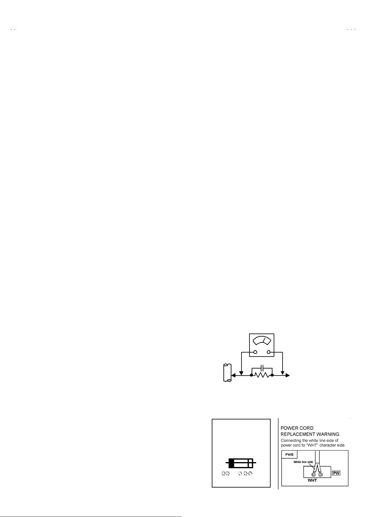
(2) Leakage Current Check
Plug t he A C line cord direct ly i nt o th e AC ou tlet ( do not u s e a
line is olation transf ormer during t his che ck.) . Using a " L eakage
Current Test er", m ea s ur e t he leakag e cur r en t fr om each
exp ose d m eta l par t of th e c a bi ne t, p ar tic ul ar l y an y expo sed
metal part having a retu rn path to t he ch assis, to a kn own good
ea rt h gr o und ( water p ipe, etc.) . A ny l ea k ag e c ur r en t must not
exce ed 0.5m A AC ( r .m. s.) .
Howev e r, in t ro pical a rea, this m ust no t e xc eed 0 .2m A AC
(r.m.s.).
"""" Alte rn at e Che ck M et hod
Plug t he A C line cord direct ly i nt o th e AC ou tlet ( do not u s e a
line isolation transformer during this check.). Use an AC
vol tm et er h av i ng 100 0 ohm s per vol t or m ore s en s iti vity in the
follo win g ma nne r. Connec t a 1 50 0Ω 1 0W resi s tor pa ralle l ed
by a 0.15μ F AC-typ e cap acitor b etwe en an exp ose d m eta l
p art and a k no wn go od earth gr ou nd (wate r pi p e, et c .).
Measu re th e A C vo ltag e acr os s th e r esist or wit h t he AC
voltmeter. Move the res istor connection to each exposed metal
part, particularly any exposed metal part having a return path to
th e ch assis , an d m ea sur e t he A C volta ge acr oss th e r esisto r.
Now, reve rs e the plu g i n t he A C out let a nd r ep e at e ach
measu rem ent. An y volta ge measu red m us t not exce ed 0.7 5V
AC (r.m. s.) . This corresponds t o 0 .5 mA AC ( r.m.s.).
Howev e r, in tr op ic al ar ea, this m ust n ot excee d 0.3V AC
(r.m.s.). This corr esp on ds t o 0 .2mA A C (r.m.s.).
AC VOLT METER
(HAVING 1000 Ω/V,
GOOD
EARTH
GR OUND
11 . High voltage hold down circuit check.
Af ter rep ai r of th e high vol t age h ol d d own c i r cuit, th is ci rcu it
sh all be c hec ked to op er ate cor rectly.
See item "Ho w to check the high voltage hold down
cir cuit".
This mark shows a fast
operating fuse, the
letters indicated below
show the r ati ng.
0.15μF AC-T YPE
1500Ω 10W
OR MOR E SENSIT IVITY)
PLACE THIS PROBE
ON E A C H EX PO SE D
ME T AL PA RT
A V
No. 51948
3
Page 4
A
V-36D503
A
A
V-36D303
V-36D203
FEATURES
"
Ti tle T EL E-T EXT br oa dcast of C 1, C2, T1 , a nd T 2 f ormu l a i s rece ivable.
" The voice multiplex f unction of the MTS system is b uilt in.
"
By t he TH EATE R PR O funct ion, a r ea l it y to w hich i t is view i ng and l i sten i ng in th e movie t he ater c an be tas ted .
"
By t he EZ S URF f unc tion, c hann el ID a nd a pr og ra m na me ar e displ aye d i n the s creen au to ma tic all y [ Only f or AV- 36D 50 3].
"
By the COMPU LINK Ⅲ function, operation interlocked with the DVD deck can be performed from remote control.
"
By the three-line digital comb filter, the refreshed image can be seen.
" Tw o p ro gram s ca n be d is playe d on th e s cree n b y th e 2 tun er PI P ci r cuit [O nly f or AV-36 D 50 3].
"
Exp ressi on of a f avor i te scre en can be ch osen b y the VIDE O STA TUS fu nction .
" A program c an be enjoyed with a powerful sound by the HYPER SURROUND function.
"
Sinc e the V chip is built i n, i t c an cho ose, view a nd l ist en to a h ealt hy pro gram .
" The RETURN P LUS f unct i on is bu ilt in .
"
A q ui ck f avorite prog r am c an be look ed for b y th e HYP ER- SC AN fun ctio n.
"
Since the co mp on ent si gn al inp ut t ermi n al i s e qui p pe d, it r ea pp ears dir ect with out deter ior a ting the si gn al fr om D VD.
FUNCTIONS
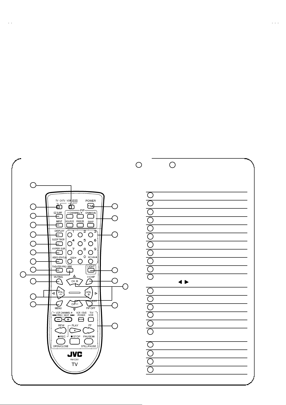
REMOTE CONT RO L UNIT (RM-C2 51, RM-C2 52)
This illustration is written about RM-C251. There are no buttons of EZ SURF and PIP in the RM-C252.
20
21
1
VCR / DVD KEY
1
TV / CATV KEY
2
20
13
21
3
4
14
5
6
7
8
15
9
10
16
2
INPUT KE Y
3
DISPLA Y KE Y
4
SLEEP TIMER KE Y
5
HYPER SURROUND KEY
6
VIDEO STATU S KEY
7
TH EATE R PRO KEY
8
BB E KE Y
9
MUTING KEY
10
11
VOL U ME -/ + an d
CURS OR / KEY ( In t he ME NU scr een )
17
MENU KEY
12
11
12
18
19
POWE R KEY
13
CHANNEL NUMBER KEY
14
LIG HT KEY
15
V-CHI P K EY
16
17
CHANNEL +/- an d
CURSOR ▲/ ▼ KE Y ( In th e MEN U sc r ee n)
EX IT KE Y
18
VCR CONTROL KEY
19
EZ SU RF KE Y [Only f or RM-C 25 1]
20
PIP CON TRO L K EY [O nl y f or R M- C25 1]
21
4
No. 51948
Page 5
A
3
A
3
A
3
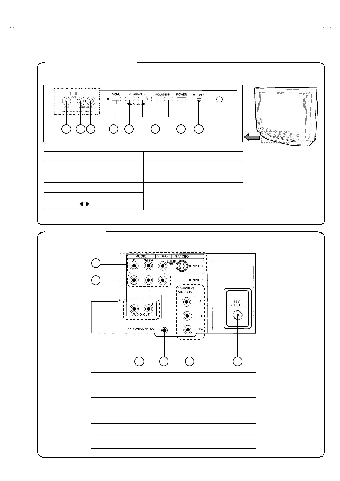
FRONT PANEL CONTROLS
1 2 3 4 5 6 7 8
① INPUT 3 VIDEO TERMINAL ⑥ VOLUME -/ + KEY
②
INPUT 3 AUDIO L TERMINAL
⑦
POWER KEY
V-36D50
V-36D30
V-36D20
③
INPUT 3 AUDIO R TERMIN AL
④
MENU KEY, CURSOR ▼ KEY
⑤
CHANNEL -/+ KEYS
CURSOR / KEYS
REAR TERMINAL
1
2
⑧
ON TIM ER / POWER LED
3 4 6 5
①
INPUT 1 TERMINAL (S-VIDEO, V, L, R)
②
INPUT 2 TERMINAL (V, L, R )
③
AUDIO OUTPUT TERMINAL
④
AV COMPULINK Ⅲ TER MINAL
⑤
ANTENNA TERMINAL
⑥
INPUT2 COMPO NENT SIGNAL TERMINAL (Y, PB, PR)
No. 51948
5
Page 6
A
V-36D503
A
A
)
)
)
V-36D303
V-36D203
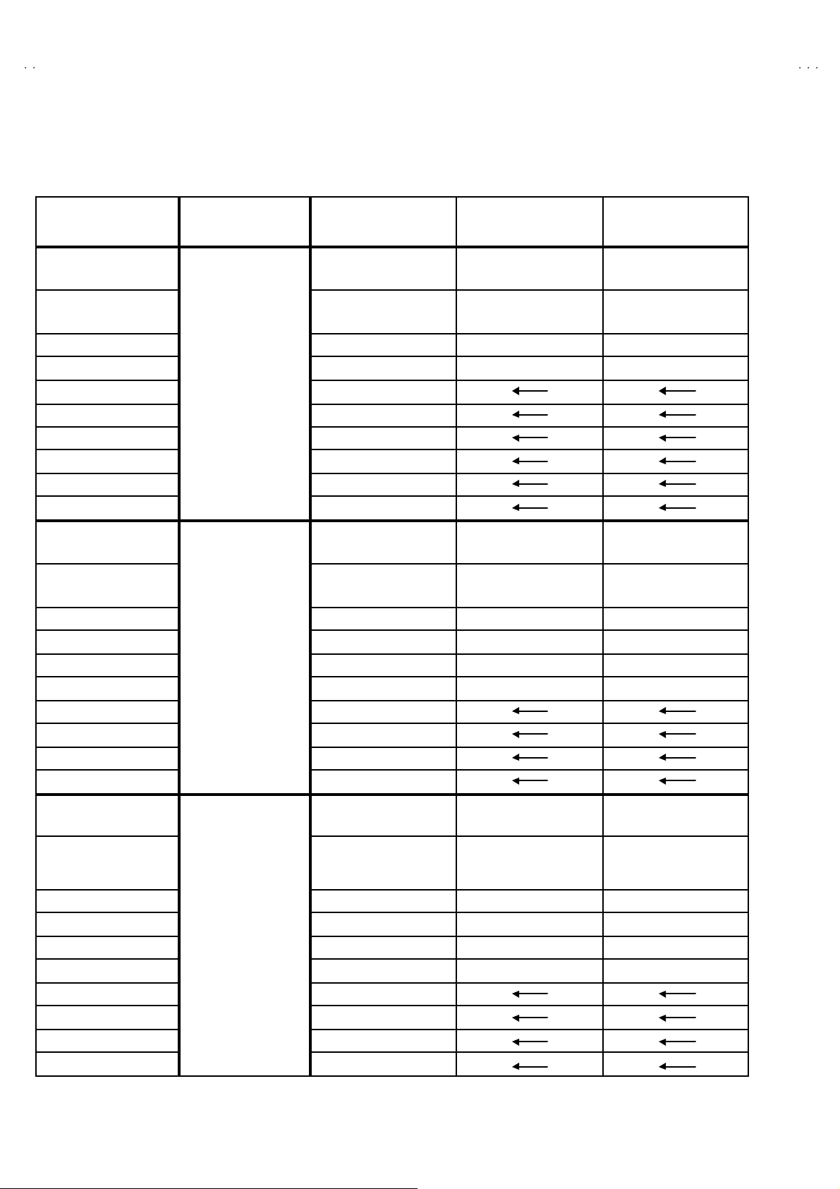
MAIN DIFFERENCE LIST
PARTS NAME MODEL /Y /R /M
ITC TUBE
(Inc. D Y, PC MAGNET,
WEDGE
DEG COIL
MAIN PWB SGE-1018A-M2 SGE-1019A-M2 SGE-1001A-M2
CRT SOCKET PWB
IP PWB SGE-4001A-M2
AV-3 6D50 3
E-COAXIAL ASSY
CO NTROL K NOB LC2021 7-00 5B-A
FRONT CA BI . ASSY
DOO R LC2040 9-00 5B-A
REM OC O N UN IT
ITC TUBE
(Inc. D Y, PC MAGNET,
WEDGE
DEG COIL CELD067-001JA
MAIN PWB SGE-1025A-M2 SGE-1026A-M2 SGE-1005A-M2
CRT SOCKET PWB SGE-3010A-M2 SGE-3011A-M2 SGE-3003A-M2
PIP PWB
AV-3 6D30 3
E-COAXIAL ASSY ×× ×
CO NTROL K NOB LC2021 7-00 5B-A
FRONT CA BI . ASSY LC1064 2-00 4C-A
DOO R LC2040 9-00 5B-A
REM OC O N UN IT
ITC TUBE
(Inc. D Y, PC MAGNET,
WEDGE
DEG COIL
MAIN PWB SGE-1025A-M2 SGE-1026A-M2 SGE-1005A-M2
CRT SOCKET PWB SGE-3010A-M2 SGE-3011A-M2 SGE-3003A-M2
AV-3 6D20 3
PIP PWB
E-COAXIAL ASSY ×× ×
CO NTROL K NOB LC2021 7-00 1C-A
FRONT CA BI . ASSY LC1064 2-00 1H-A
DOO R LC2040 9-00 1D-A
REM OC O N UN IT
A90AHH50X10/V/ A90AEJ15X01 A90LLD361X15
CELD067-001JA
SGE-3010A-M2 SGE-3011A-M2 SGE-3003A-M2
WJX0014-002A
LC1064 2-00 4C-A
RM-C 251- 1H
A90AHH50X10/V/ A90AEJ15X01 A90LLD361X15
×× ×
RM-C 252- 1H
A90AHH50X10/V/ A90AEJ15X01 A90LLD361X15
CELD067-001JA
×× ×
RM-C 252- 1H
CELD067-001JA
or
QQW 0136 -001
CELD067-001JA
or
QQW 0136 -001
CELD067-001JA
or
QQW 0136 -001
QQW 0114 -001
or
QQW 0106 -001
QQW 0114 -001
or
QQW 0106 -001
QQW 0114 -001
or
QQW 0106 -001
6
No. 51948
Page 7
A
V-36D50
3
A
3
A
3
V-36D30
V-36D20
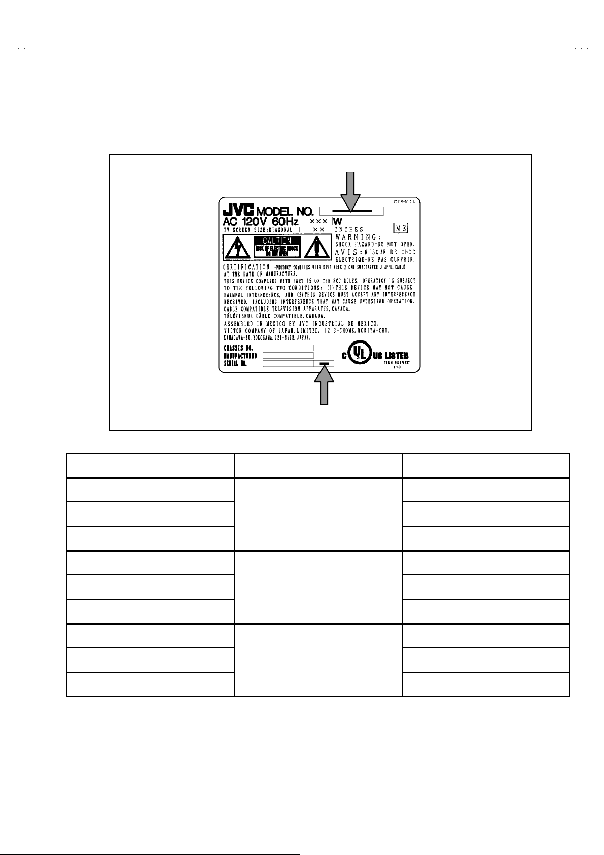
HOW TO IDENTIFY MODELS
How to r ec ogn i ze fr om th e ap p ear an ce of th e mo de l co ncern ed i s wr itt en b el o w. Ple ase dist ingu is h f r om se veral c ont ents cu rren tl y printed on
th e r at ing l a bel.
Model Name
Detailed Model Name
Model Name Detailed Model Number
AV-36D503 /Y Y
AV-36D503 /R R
AV-36D503 /M
AV-36D303 /Y Y
AV-36D303 /R R
AV-36D303 /M
AV-36D203 /Y Y
AV-36D203 /R R
AV-36D203 /M
AV-36D503
AV-36D303
AV-36D203
M
M
M
No. 51948
7
Page 8
A
V-36D503
A
A
C
V-36D303
V-36D203
SPECIFIC SERVICE INSTRUCTIONS
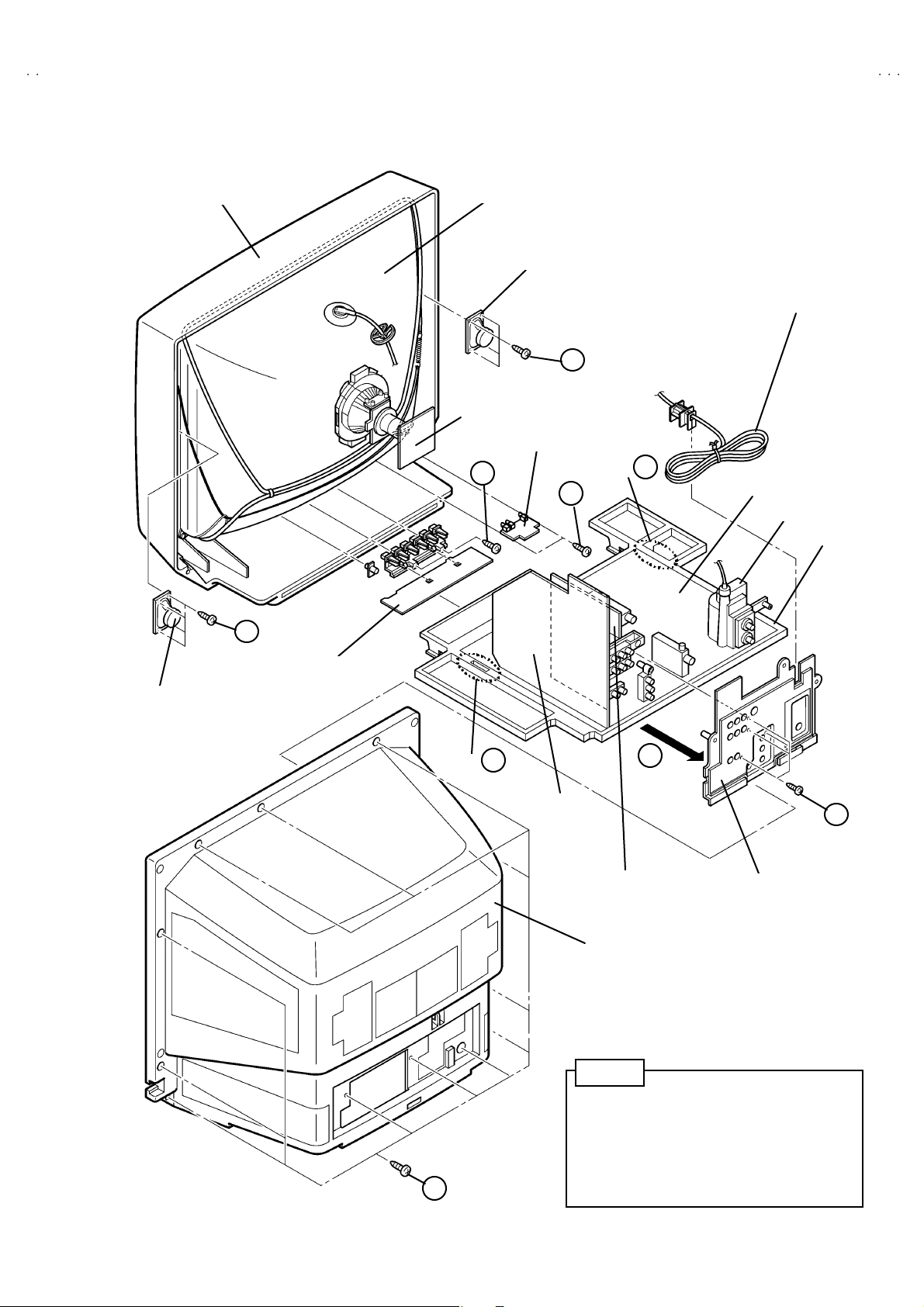
DISASSEMBLY PROCEDURE
REMOVING THE REAR COVER
"
Unplug t he power plu g.
1. As s hown in Fig.2 , r emove the 12 scr ews marked
2. Remove the rear cover toward you.
Note :
When re i nsta lling th e rear cov er , c are fu lly pus h it inw ar d af ter
inserting the chassis into the rear c over groove.
!!!!
.
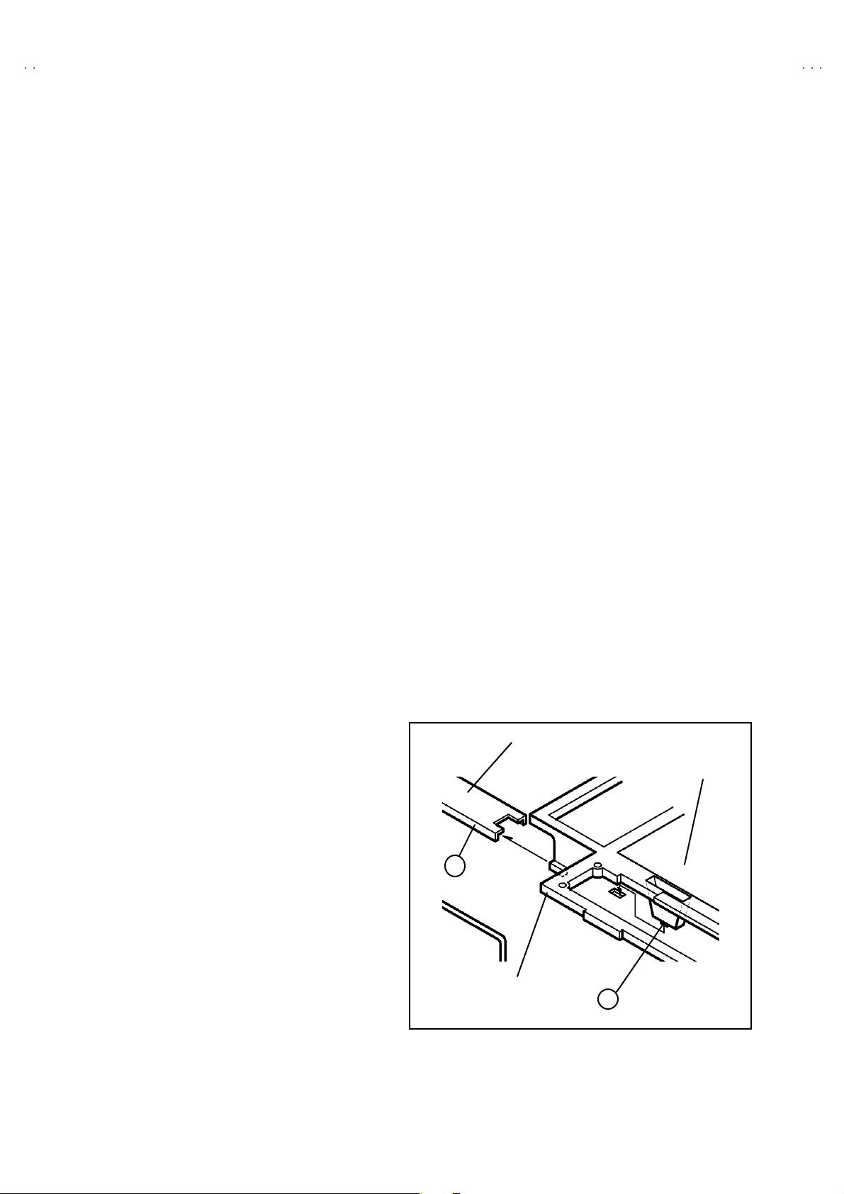
REMOVING THE CHASSIS BASE
"
After removing the rear cover.
1. Slight l y r ai se th e bot h s ides of th e chass is bas e b y ha nd , and
remove the 2 cl aw s m ar ked "
sides of the chassis from the chassis rail.
2. As sho wn i n F ig .1, dra w t he ch as sis base b ackward al on g t he
chassis rail m arked #
(If necessary, detac h the wire clamp, connec tor’s etc.)
Note :
When con du cting a c hec k with po we r sup pl i ed , b e su re to conf irm
th at th e CRT ea rt h wire i s c onn ect ed to the CRT SOCKET P W B
an d t he MA IN PW B .
#in the arrow dire ction marked $$$$(Fig.2.).
##
" ( Fig. 1 a nd F i g.2 ) unde r th e both
""
REMOVING THE TE RMINAL BOARD
" After removing the rear cover.
1. As s hown in Fig.2 , r emove the 4 screws marked%&
2. When you pu ll ou t th e TE RMIN AL BOARD, it ca n b e re mo ved .
%&
%&%&
.
REMOVING THE SPEAKER
" After removing the re ar cover and chassis base.
1. As s hown in Fi g.2 , r em ove t he 4 screws marke d )
2. F ol low th e s ame st eps wh en rem ovin g the oth er h and spe ake r.
).
))
CHECKIN G THE MAIN PW BOARD
1. T o ch eck the ba ckside of t he MA IN PW Boar d.
(1) Pu ll ou t th e c has sis b as e . (Refe r to RE MO VING T HE
CHA SSIS BASE) .
(2) Erect the chassis vertic ally so t hat you can easily check from
the backside of the MAIN PWB.
CAUTION
" W hen er ec ti ng th e chass is, be c arefu l so t hat the r e will be n o
con tact in g with ot her P WB.
" Be for e tu rn i ng on po wer , make s ur e th at th e C RT e ar th w ir e and
oth er co nn ec to rs are p ro per l y co nn ecte d.
WIRE CLAMPIN G AND CABLE T Y ING
1. Be sure t o clamp th e wir e.
2. N ever remo ve th e cable ti e used f or tyi ng the w i re s to gether.
Sh oul d it be i n adv e rt ent l y rem ove d, be su r e to tie the wires with
a n ew c able tie.
REMOVING THE FRONT CONTROL PW BOARD
"
After removing the re ar cover and ch assis base .
1. As s hown in F ig.2, rem ove t he 2 screws marked '
FRONT CONTROL PWB with th e front cabin et.
2. Then remo ve th e FRONT CONTROL PW B.
'att ach ed the
''
REMOVING THE FRONT AV IN PW BOARD
" After removing the rear cover and chassis base.
1. As s hown in Fig.2 , remove the 2 screws marked
2. Then remo ve th e FRONT A V IN PW B.
((((
.
FRONT CABINET
MAIN PWB
CHASSIS BASE
B
Fig. 1
8
No. 51948
Page 9
A
V-36D50
3
A
3
A
3
V-36D30
V-36D20
FRONT CABINET
H
CRT
SP EAKER
CRT SOCKET PWB
FRONT AV IN PWB
F
POWER CORD
H
CLAW
B
MAIN PWB
G
HV T
CHASSIS BASE
SP EAKER
FRONT CONTROL PWB
A
CLAW
B
AV SE L PWB
D
PIP PW B
[Only for A V -36D 50 3]
REAR COVER
No te
Thi s ill ustr a tion de scrib es ab out A V- 36 D503 .
Alth ou gh t he AV- 3 6D30 3 a nd AV -36D2 03 a r e
sl ig htl y di ff erent from t his illus tr ati on , it can u se for
AV -3 6D 30 3 and AV- 36 D 20 3 in the s am e s tep s as
this illustration.
TERMINAL BOARD
E
Fig.2
No. 51948
9
Page 10
A
V-36D503
A
A
V-36D303
V-36D203
MEMORY IC REPLACEMENT
1. Memory IC
This model uses the memory IC.
Thi s m em or y IC st ores d ata f or pr oper o pera tion of the vide o/ch ro ma a nd d eflecti o n c ircui ts.
When r ep la c ing, be sure to use th e IC c ont ai ni n g i ni ti a l se tting data .
2. Memory IC replacement procedure
(1) Power off
Switch off th e pow er an d di s con nec t th e p ow er plu g f rom t he AC ou tlet.
(2) Replace the memory IC
Be sure to use the memory IC written with the initial setting values.
(3) Power on
Connect th e pow er pl u g t o the AC ou tl et an d switch on th e pow er .
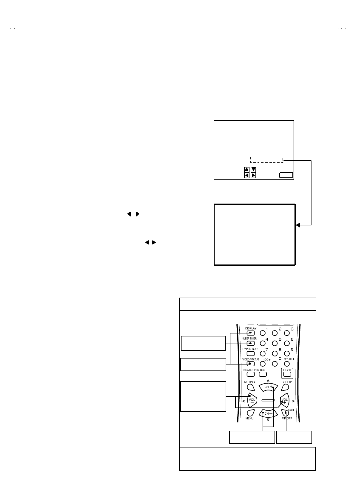
(4) System constant check and setting
①
Press the SL E EP T IM ER ke y and se t SL EEP T IM ER f or 「0 min」.
②
Be for e di s a pp ear t he display of SL EEP T IM ER s ett ings, si mu l tan eo usly
press th e DISPLAY ke y and VI DE O ST ATUS key of t he remot e control unit.
The SERVICE MENU screen of Fig.1 will be displayed.
③
While the SERVICE MENU is displayed, select the SYSTEM(SYS) item
wi t h CURSOR ▼/▲ key an d g o in to with / key s. T h en the S YST E M
mode screen will be displayed as shown in Fig.2.
④ Refe r to t he ta ble of SY STEM CONSTAN T given in pa ge la ter , an d ch ec k
th e eac h i tem . If the v alu e i s diff eren t, s el ect t he settin g item with th e
CURSOR ▼/▲ ke y, an d s etti n g w it h the CURS OR / keys. (The let ters
of the selected item is displayed in yellow.)
⑤ When adj ust me nt h as c ompl ete d, the values st ore i nt o memor y IC
automatically.
⑥
Press the EX IT ke y twic e t o retur n to the normal scree n.
SE RVICE MENU
SERVICE MENU
1.V/C(S) 2.DEF(D)
3.SOUND(A) 4. O THERS
5.PIP(PIP) 6.3L Y/C(LYC)
7. LO W LIG HT 8. HIGH LI G HT
9.RF AFC 10.VCO
2
C BUS 12.SYSTEM(SYS)
11.I
SELECT BY
OPERATE B Y EXIT BY
Fig.1
12. SY STE M (SY S) MODE
SYS01 VIDEO
Fig.2
EXIT
***
(5) Receiving channel setting
Refe r to the OP ERATING INS T RUCTIONS an d set th e receive
channels (Channels Preset) as described.
(6) User settin gs
Check t he us er se tting i t ems accor di n g to th e Ta ble 2 given in pag e
later.
Wher e th ese d o not a gr ee , refe r to the OPERAT ING
INSTRUCT IONS an d s et t he i tem s as desc rib ed.
(7) SERVICE MENU setting
Ve rif y wh at to se t i n t he SERV IC E M ENU, and s et w h at ever is
necessary (F ig.1 ) . Refer to th e SE RVIC E A DJUSTM ENT f or set ting.
KEY ASSIGNMENT OF REMOTE CONTROL UNIT
①
Setti ng fo r “0 min”
②
Simulta neously push
③
Go into th e ite m
④
Setti ng th e value
③, ④
Se le ct t he it em
Alth ou gh t hi s illus tr ati on of re mo te c ont ro l unit is written ab ou t
RM-C251 (AV-36D503), it can use for operating RM-C252 (AV-
36D303, 203) as same key assignment.
EXIT from
SY STEM m od e
10
No. 51948
Page 11
A
3
A
3
A
3
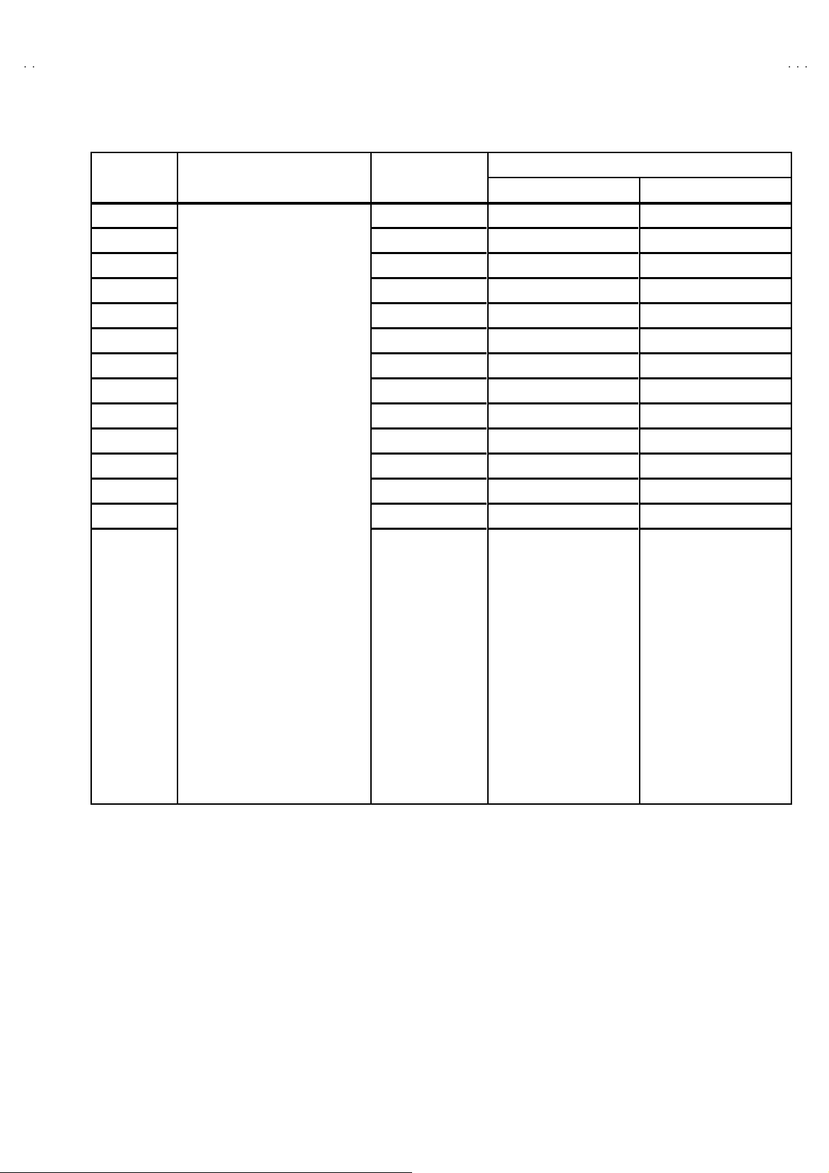
VALUES OF SYSTEM CONSTANT (TABLE 1)
V-36D50
V-36D30
V-36D20
ITEM CONT ENTS VARIABLE RANGE
SY S01 VIDEO IN 0~4
SY S02 PIP 0~1
SY S03 3D Y/ C 0~1
SY S04 Y C V 0~1
SY S05 C CD PC HK 0~1
SY S06 PU R ITY 0~1
SY S07 VM 0~1
SY S08 N OISE CR 0~1
SY S09 C LR TEM P 0~1
SY S10 T HEATE R 0~1
SY S11 T HEATE R PRO 0~1
SY S12 BB E 0~1
SY S13 HYP SURR 0~1
SY S14 16:9 MD 0~1
SY S15 HYP S CA N 0~1
SY S16 EZ SUR F 0~1
SY S17 ID DISP 0~1
SY S18 COMPULINK 0~1
SY S19 CCD 0~1
SY S20 VCHIP 0~1
SY S21 VCHIP CA 0~1
SY S22 JVC L OGO 0~1
SY S23 CMP IN 0~1
INITIAL SETTING VALUE
AV-36D503
33
10
00
11
11
00
00
00
11
11
11
11
11
00
11
10
11
11
11
11
11
11
11
AV-36D303, 203
SY S24 CXA1 87 5 0~10 0
No. 51948
11
Page 12

A
V-36D503
A
A
V-36D303
V-36D203
VALUES OF USER SETTING ITEMS (TABLE2)
Setting of switches on fr ont panel and remote control unit
ITEM INITIAL SE TTING VALUE ITEM INITIAL SETTING VALUE
POWE R OFF DISPLA Y OFF
CHA NNEL CABL E CH-0 2 VIDEO STATU S DYN AM IC
VOLUME 10 PIP SOURCE CABLE CH-04 [Only AV-36D503]
INPUT TV PIP POS ITION Left lo wer side [Only A V-36D503]
HYPE R S U RROU ND OFF SLEEP TIMER 0
BB E ON
Setting of MENU scr een
PICTURE ADJUST INITIAL SETUP
TINT CENTER LANGUAGE ENG
COLOR CEN TER FR ONT PAN EL LO CK OFF
PICTURE +8 V2 COMPONENT-IN NO
BRIGHT CENTER AUTO SHUT O FF OFF
DETAIL +10 XDS I D ON
COLOR TEMPERATURE HIGH CLOSED CAPTIO N OFF
NOISE M UT ING ON CAPT IO N : CC1
TEXT : T1
SOUND ADJUST AUTO TUNER SET UP TUNER MODE : CABLE
BA SS C EN TER CHA NNEL SUMMARY Unn ecess ar y to set
TREBLE CENTER V-CHIP OFF
BALANCE CENTER SET US TV RATINGS ALL CLEAR
MTS STEREO SET MOVIE RATINGS ALL CLEAR
CLOCK / TIMERS SET CANADIAN RATINGS ENG ALL CLEAR
MANUAL SET CANADIAN RATINGS FRE ALL CLEAR
SE T CLOC K
ON/OFF TIMER OFF
TIME ZONE : PACIFIC UNRA TED VIEW
D.S.T : OFF SET LOCK CODE “0000”
12
No. 51948
Page 13

A
3
A
3
A
3
SERVICE ADJUSTMENTS
BEFORE STARTING SERVICE ADJUSTMENT
1. There are 2 wa y of a dju sting t his TV: One is with t he remote
control unit and the other is the conventional method using
adjustment parts and components.
2. The adjustment with the REMOTE CONTROL UNIT is made
on the basis of t he initial setting v alue s. The sett ing va lues
which adjust the screen to its optimum condition may differ
from the init ia l s etting v al ues.
3. Make s ur e th at c onn ect i on i s c orrec t ly ma de t o AC p ower
source.
4. Turn on the p ower of th e se t an d equipmen t bef or e us e, an d
start t he ad ju stm en t proc edure s af ter waitin g at least 30 mi n utes.
5. Unless ot her wi se spec if i ed, p r ep are th e mo st suita bl e r ec epti o n
or inp ut sign al for adjust ment.
6. Never touc h an y ad j ustm en t part s, wh ich ar e n ot sp ecif ie d i n the
list for this adjustment VRs, transforms, condensers, etc.
7. Pr ep arati o n f or ad justm en t
Unless otherwise specified in the adjustment instructions, preset
the following functions with the REMOTE CONTRO L UNIT.
User menu preset value
VIDEO STATU S STA NDARD
TINT, COLOR, PICTURE
BRIGHT, DETAIL
NOISE M UTI NG OF F
COLOR TEMPERATURE
PIP [Only for A V-36D503]
BA SS, TREB LE, BA LANCE
H YPE R S U RRO U ND
MTS
V-36D50
V-36D30
V-36D20
MENU ITEM PR ES ET V ALU E
CENTER
LOW
OFF
CENTER
OFF
STEREO
MEASURING INSTRUMENT AND FIXTURES
1. DC voltmeter (or digital voltmeter)
2. Oscilloscope
3. Si gn al g en er ator (P attern g en erat or) [ NTS C]
4. Remote control unit
5. TV a ud io m ulti pl e x sign al ge ne rator
6. F requ enc y cou nte r
ADJUSTMENT ITEMS
BASIC ADJUSTMENT
!
Check of B1 pow er s upp l y
! MAIN / S U B VCO ad justment
!
RF AGC ad jus tm ent
! FOCUS adjustment
DEFLECTION CIRCUI T ADJUSTMENT
!
V. CENTER / V SIZE ad ju stment
! H SIZE / H POSITION / SIDE PINCUSHION adjustment
VIDEO / CHROMA CIRCUIT ADJUSTMENT
!
WHITE BALANCE adjustment ~LOW LIGH T ~
!
WHITE BALANCE adjustment ~HIGH L IGHT~
! SUB B RI GH T adjustment
!
SUB CONTRAST adjustment
! SUB COLOR adjustment
!
SUB TI NT adjus tment
PIP CIRCUIT ADJUSTMENT
! WHITE BALANCE adjustment ~HIGH LIGHT~
!
DISPL A Y POS ITION a djust me nt
MTS CIRCUIT ADJUSTMENT
! IN PU T LE VEL c h eck
!
SE PARATIO N adjustm ent
No. 51948
13
Page 14

A
V-36D503
A
A
[
]
V-36D303
V-36D203
ADJUSTMENT LOCATIONS
FRONT CONTROL PWB
POWER ME N UVOL CH
IC7701
CN7007
FRONT
FRON T
FRONT AV IN PWB
F
FRON T
MAIN PWB
SS
AV SELECTOR PWB
PI P PWB
On ly for AV-36D503
T
CN001
CN002
CN003
TUNER
CN007
MEMORY IC
IC101
IC702
IC201
CN004
TUNER
PW
F901
FUSE
FUSE
FUSEFUSE
DEG.
1:TP-91(B1)
2:NC
3:TP -E ( )
HV
3
HVT
HVT
HVTHVT
1
B1
T111
VCO
VCO
VCOVCO
14
V CENTER SW
V CENTER SW
V CENTER SWV CENTER SW
No. 51948
U
S421
E1
CRT EARTH
(BRAID ED AS S' Y)
UPP ER : FOCUS
LOWER : SCREEN
Page 15

A
3
A
3
A
3
CRT SOCKET PWB
(
)
[
]
SOLDER SI DE
V-36D50
V-36D30
V-36D20
TOP
CN 300 4
TP-G
TP-R
TP-E( )
TUNER
TP-B
CN 30E2
CR T EART H
(BRAIDED ASS'Y)
CN 300 5
PIP PWB
Only for AV-36D503
TOPFRONT
I C4101
SUB VCO
SUB VCO
SUB VCOSUB VCO
T 4111
No. 51948
15
Page 16

A
V-36D503
A
A
V-36D303
V-36D203
BASIC OPERATION OF SERVICE MENU
1. TOOL OF SERVICE MENU OPERATION
Operate the SERVICE MENU with the REMOTE CONTROL UNIT.
2. SERVICE M ENU ITEM S
With th e SERVIC E ME NU, v ar i ous ad ju stm ent s can be m ad e, an d th ey ar e b r oad ly c l assi fi ed in th e foll ow i ng item s of a djust ments.
(1) V/C(S)・・・・・・・ ・・・・・・・・・・・・・ ・・・・・・・・・・・・ ・VIDEO / CHROMA related circuit adjustment mode
(2) DEFLECTION(D) ・・・・・・・ ・・・・・・・・・・・・・ ・・・DEFLEC T IO N re l ate d ci r cuit adju stme nt mod e
(3) SOUND(A)
(4) OTHERS(F) ・・・・・・・ ・・・・・・・・・・・・・ ・・・・・・・・Whole system related items adjustment mode
(5) PIP(PIP)[Only for AV-36D503]
(6) 3L Y/C(LYC) ・・・・・・・ ・・・・・・・・・・・・・ ・・・・・・・3 li n e YC s eparation r el at ed c ircu it adj ustm en t mod e
(7) LOW LIGHT
(8) HIGH LIGHT ・・・・・・・・・・・・・・・・・・・・ ・・・・・・・W hi te balance of “HIGH L IGH T” a dj ustm e nt mode
(9) RF AFC ・・・・・・・ ・・・・・・・・・・・・・ ・・・・・・・・・・・ RF AF C r el at ed c ircui t a djust m ent mo de
( 10) VCO ・・・・・・・・・・・・・・・・・・・・ ・・・・・・・・・・・・ ・・VCO related circui t a djust ment mode
( 11) I2C BUS ・・・・・・・ ・・・・・・・・・・・・・・・・・・・・・・・・ I2C bus r elat ed c i r cuit ad ju stm en t mod e [Fixed on]
( 12) SY STEM(SY S) ・・・・・・・ ・・・・・・・・・・・・・・・・・・This m od e is u sed w he n s etti ng up the wh ole s ys tem.
・・・・・・・ ・・・・・・・・・・・・・ ・・・・・・・・・
・・・・・・・ ・・・・
・・・・・・・ ・・・・・・・・・・・・・ ・・・・・・・
SOUND related circuit adjustment mode
PIP relat ed circ ui t adju stm ent mod e
White bal a nc e of “LO W LIG HT ” ad ju stm en t m od e
3. BASIC OPERATION OF SERVICE MENU
(1) Ho w to enter SERVICE MENU
Press the SLE EP TIMER key and set the SLE EP TIME R for
[0 MIN].
The n press th e DI SPLAY key an d th e VI DE O ST AT US key of the
remote control unit simultaneously, and the SERVICE MENU
scr een will be di splaye d as shown b el ow .
(2) Selection of SUB MENU SCREEN
In SERVI CE MENU, press the CURSOR ▲▲▲▲/▼▼▼▼ key to select any of
th e SU B ME NU ite ms. (Th e l ett ers of th e s el ect ed it ems ar e
displayed in yellow)
If an i te m l i ke to set up becomes yellow , the CURSOR / key
will be pushed and it will go into the mode.
SERVICE MENU
1.V/C(S) 2.DEF(D)
3.SOUND(A) 4. O THERS
5.PIP(PIP) 6.3L Y/C(LYC)
7. LO W LIG HT 8. HIGH LI G HT
9.RF AFC 10.VCO
2
C BUS 12.SYSTEM(SYS)
11.I
SELECT BY
OPERATE B Y EXIT BY
SE RVICE MENU
EXIT
KEY ASSIGNMENT OF REMOTE CONTROL UNIT
①
Setti ng fo r “0 min”
②
Simulta neously push
③
Go into th e ite m
④
Setti ng th e value
③, ④
Se le ct t he it em
Alth ou gh t hi s illus tr ati on of re mo te c ont ro l unit is written ab ou t
RM-C251 (AV-36D503), it can use for operating RM-C252 (AV36D303, 203) as same key assignment.
EX IT
CURSOR ▲/▼ key
Select 1 .V/C( S)~12.S YSTEM(SYS)
1.V /C(S)
2. DEF (D)
11 .I2C BUS
12.SYSTEM(SYS)
16
CURSOR / key
Go into eac h S UB M ENU
No. 51948
VI DEO/C HROM A
DEF LECT ION
SO UND
Page 17

A
3
A
3
A
3
(3) Method of Setting
For example, the operation in the case of s etting up VIDEO/CHROMA is expressed below.
EX IT key
Retu rn to t he S ERVIC E
ITEM CONTENTS
ME NU MA IN
S01 BRIGHT
S02 PICTURE
S03 COLO R
RF 4 : 3 STD LOW
S04 TINT
S05 DETAIL
S06 BRIGHT +-
S07 PIC T +-
S08 COLO R +-
S09 TINT + -
S10 DETAIL +-
S01 B RIGHT
S02 PI CTUR E
S03 C OLOR
S04 T I NT
***
***
******
***
***
******
***
***
******
***
***
******
V-36D50
V-36D30
V-36D20
CURSOR ▲/▼ key
Se le ct t he it em s fr o m
CURSOR / key
S01 t o S1 0.
Increment or decrement
th e a djust ment value
(4) Others [Only for AV-36D503]
If go in to the 9. RF A F C an d 1 0.VCO item s, there will b e display t he R F AF C M AIN scr een and VC O MA IN s creen .
Then press the CURSOR / key, the RF AFC SUB screen and VCO SUB screen is displayed.
10.VCO SUB 10.VCO MAIN
TUN ER SUB
HIGH LE VEL
REFE REN CE LEVEL
LOW LEVEL
SYN C NO
9.RF AFC MAIN MODE
CURSOR / key
TUN ER SUB
HIGH LE VEL
REFE REN CE LEVEL
LOW LEVEL
SYN C NO
9.RF AFC SUB
CURSOR / key
TOO HI GH GOOD TOO LOW
TUN ER MA IN
AFC ON
FINE **
No. 51948
TOO HI GH GOOD TOO LOW
TUN ER SUB
AFC ON
FINE
**
17
Page 18

A
V-36D503
A
A
V-36D303
V-36D203
SERVICE M ENU (M AIN MENU)
SE RV IC E MEN U
1.V /C (S ) 2 .D EF( D )
3.SOUND(A) 4.OTHERS(F)
5.P IP(PIP) 6.3L Y/C(LYC)
7.LOW LIGH T 8.H IGH LIGHT
9.RF AFC 10.VCO
2
C BUS 12.SYSTEM(SYS)
11.I
SELECT BY
OPE RA TE B Y EX IT BY
EX IT
1 .V/ C( S)
R F 4 : 3 S TD L OW
S01 BRIGHT
***
3.SOUND( A)
A 01 IN LE VEL ***
5.PIP(PIP) [Only for AV- 36D503]
2.DEF(D)
R F 4 : 3 S TD L OW
D01 V FREQ
4.OTHERS(F)
F01 OSD POSI ***
6.3L Y/C(LYC)
[Do n ot adjust ]
***
8.HIGH LIGHT
*** ***
2
11.I
C BUS
[Do n ot adjust ]
2
I
C BUS O N
12.SYSTEM(SYS)
PIP01 BRIGHHT ***
7.LOW LIGHT
BR IGH T
***
***
***
***
9.RF AFC MAIN MODE
TOO HIGH GOOD TOO LOW
TU NE R M AI N
AF C ON
FINE **
10.VCO MAIN
LYC01 MODE
***
9.RF AFC SUB [Only for AV-36D503]
TOO HIGH GOOD TOO LOW
TU NE R SU B
AF C ON
FINE
**
10.VCO SUB [Only for AV-36D503]
***SY S01 VI DE O
18
TU NE R M AI N
HI G H LE VE L
RE FE RE N C E LE V EL
LO W L EVE L
SY NC NO
No. 51948
TU NE R S UB
HI G H LE VE L
RE FE RE N C E LE V EL
LO W L EVE L
SY NC NO
Page 19

A
V-36D50
3
A
3
A
3
V-36D30
V-36D20
INITIAL SETTING VALUE O F SERVICE MENU
1. Adjustment of the SERVICE MENU is made on the basis of the initial setting values ; ho wev er, the new setting values which
set the screen in its optim um condition may differ from the initial setting.
2. Do no t change the init ial sett ing value s not li sted in “ ADJUSTMENT”.
V / C(S) MOD E
No . Setting item Variable range
STANDARD THEATER STANDARD
S01 BRIGHT 0~127 64 --- ---
S02 PICTURE 0~127 55 --- ---
S03 C OLO R 0~127 55 --- ---
S04 T INT 0~127 64 --- ---
S05 D ETAIL 0~63 37 --- 35
S06 BRIGHT +- -32~+32 --- + 1 -2 [5 03] / ±0 [30 3, 203 ]
S07 PIC T+- -32~+32 --- -10 ±0
S08 COLOR +- - 32~+32 --- -3 -2
S09 T INT+ - - 32~+32 --- -3 +2
S10 DET AIL + - - 32~+32 ---
RF
±
0---
S-VI DEO
COM POSITE VI DEO
COMPONENT INPUT / STANDARD
No. Setting item Variable range
S03 C OLO R 0~127605649
S04 T INT 0~127647269
S05 D ETAIL 0~63 40 40 40
S06 BRIGHT +- -32 ~+32 -1 [5 03] / -3 [303, 20 3] -1 [503] / -3 [3 03, 203] -1 [5 03] / -3 [303, 20 3]
S07 PIC T+- -32~+32 ±0 ±0 ±0
S11 R CUT OFF 0~2 55 30 --- - -- - -- - -- - -- - -- - --
S12 G CUT OFF 0~2 55 30 --- - -- - -- - -- - -- - -- - --
S13 B CUT OFF 0~2 55 30 --- - -- - -- - -- - -- - -- - --
S14 R D RI VE 0~1 27 64 --- --- --- --- - -- - -- - --
S15 B DR IVE 0~127 64 --- --- --- - -- - -- - -- - --
S16 R CUT+ - -128 ~+1 27 - -- ±0 ±0 ±0 -10 --- --- ---
S17 G CUT+- -128~+1 27 --- ±0 ±0 ±0 ±0 --- --- ---
S18 B CUT+- -128~+1 27 ---
S19 R DRV+- - 128 ~+1 27 - -- +5 +13 +7 ±0 --- --- ---
S20 B DRV+- -128~+1 27 - -- +6 -25 -9 ±0 --- - -- - --
S21 N TSC MA T 0~3 33112211
S22 BL ACK S T 0~3 1 --- 1 --- --- --- --- ---
S23 D CRE ST 0 ~1 1 --- 1 --- --- --- --- ---
S24 D CRSW 0~1 1 --- 1 --- --- --- --- ---
AV-36D503 /Y
AV-36D303 /Y
AV-36D203 /Y
RF / S-VIDE O / COMPOSITE VI DEO
STANDARD THEATER STANDARD
LOW HI GH LOW HIGH LOW HIGH LOW HIGH
±
0
±
0
AV-36D503 /R
AV-36D303 /R
AV-36D203 /R
COM PONENT IN PUT
±
0 -10 --- --- ---
AV-36D503 /M
AV-36D303 /M
AV-36D203 /M
THEATERNo . Setting item Variable range
No.51948
19
Page 20

A
V-36D503
A
A
V-36D303
V-36D203
No . Se tt ing ite m Va riabl e range RF
S25 AS Y SHRP 0 ~7544
S26 BP F FO 0 ~10 0 ---
S27 KIL R OFF 0~10 0 ---
S28 KIL R SEN 0~11 1 ---
No. Setting item Variabl e ra nge Init ial se tting v al ue No. Setting item Va riabl e ra nge Initial set ting v al ue
S29 RGB MU TE 0 ~10S39Y MUTE0~10
S30 BLUE B 0~1 0 S40 SVM GAIN 0~30
S31 VIDEO SW 0~3 3 S41 SVM PH 0~30
S32 CMP AB CL 0~1 0 S42 WPL 0~10
S33 OSD ABL 0~1 0 S43 COL GMM 0~10
S34 OSD CON T 0~63 10 S44 V1 GAIN 0~74
S35 SUB CONT 0~15 8 S45 AGC ADJ 0~127 63
S36 AB L GA IN 0~3 0 S46 VMOFF DE -128~+127
S37 ABL PNT 0~33S47APC CLK0
S38 Y G AM MA 0~31
SOUND MODE
S-VI DEO
COM POSITE VI DEO
COM PONENT IN PUT
±
0
~
11
No. Se tting it e m Variabl e ra nge Init ial setting v al ue No. Setting item Va riabl e ra nge Initial set ting v al ue
A01 IN LEVEL 0~1 5 10 A04 SAPC 0 / 1 0
A02 LOW SEP 0~6 3 32 A0 5 BB E BA SS -128~+127 +3
A03 HI SEP 0~6 3 32 A0 6 BB E TRE - 128~+127 -4
3L Y / C MODE (Do not adjust)
No. Va riabl e ra nge Initial set ting v al ue No . Va riabl e ra nge Initial set ting v al ue
LYC01 0~74 LYC070~11
LYC02 0~71 LYC080
LYC03 0~10 LYC090~11
LYC04 0~10 LYC100
LYC05 0~15 2 LYC11 0~10
LYC06 0~10 LYC120
~
30
~
10
~
10
20
No.51948
Page 21

A
V-36D50
3
A
3
A
3
V-36D30
V-36D20
DE F M OD E
AV-36D503 /Y
AV-36D303 /Y
AV-36D203 /Y
RF
D01 V FREQ
D02 AFC GAI N 0~3020200
D03 H POSI 0~3 1 16 16 16 16 16 16
D04 H POS I+ - -128~+127 --- --- --- --- --- ---
D05 V PHASE 0~7000000
D06 V P H+ - -128~+127 --- --- --- --- --- ---
D07 V SIZE 0~+ 127 52 52 60 60 82 82
D08 V S IZE+ - - 128~+127 --- --- --- --- --- ---
D09 V CENTER 0~6 3 32 32 32 32 32 32
D10 V CENT+- -128~+127 --- --- --- --- --- ---
D11 V S CORR 0~15335555
D12 V S CO+- -128~+127 --- --- --- --- --- ---
D13 V LIN 0~15 12 12 12 12 13 13
D14 V LIN+- -128~+127 --- --- --- --- --- ---
D15 H SIZE 0~63 32 32 32 32 27 27
D16 H SIZE +- -128 ~+127 --- --- --- --- --- ---
D17 WVMT TOP 0~3000000
D18 WVM T BTM 0~3000000
D19 EWCR TOP 0~3 1 13 13 13 13 13 13
D20 EWCR T+- -128~+127 --- --- --- --- --- ---
D21 EWCR BTM 0~31 14 14 14 14 14 14
D22 EWCR B+- -128~+127 --- --- --- --- --- ---
D23 EW PARA 0~63 37 37 34 34 31 31
D24 EW PA RA +- - 128 ~+127 --- --- --- --- --- ---
D25 V EHT 0~7000000
D26 V E HT + - -128 ~+127 --- --- --- --- --- ---
D27 H EHT 0~7000000
D28 H EH T + - -128 ~+127 --- --- --- --- --- ---
D29 TRAPEZ 0~6 3 30 30 35 35 35 35
D30 TRAPEZ+- -128~+127 --- --- --- --- --- ---
D31 V AGC 0~1000000
D32 BLANK SW 0~1000000
D33 VRMP BI 0~1000000
0~3
030300
S-VI DEO
COM POSITE
AV-36D503 /R
AV-36D303 /R
AV-36D203 /R
RF
COM POSITE
S-VI DEO
AV-36D503 /M
AV-36D303 /M
AV-36D203 /MNo . Setting item Variable range
RF
COM POSITE
S-VI DEO
No.51948
21
Page 22

A
V-36D503
A
A
V-36D303
V-36D203
OTHERS MODE
No. Va riabl e rang e Initial se tting v al ue No. Variabl e ra nge Initial se t ting v al ue
F01 0~15 37 F15 0~63 0
F02 0~15 90 F16 0~63 10
F03 0~15 45 F17 0~63 20
F04 0~15 93 F18 0~255 2
F05 0~63 7 F19 -128~+127 +8
F06 0~10F20-128~+127 - 4
F07 0~63 2 F21 -128~+127 -10
F08 0~20F22-128~+127 -16
F09 0~255 5 F23 0~10
F10 0~255 5 F24 0~20
F11 0~255 16 F25 0~255 255
F12 0~63 32 F26 0~255 40
F13 0~255 3 F27 0~255 15
F14 0~255 5 F28 0~11
PIP M OD E
No. Setting item Variable range Init ial se tting value No. Setting item Variable range Initial set ting value
PIP01 BRIGHT 0~15 0 PIP28 MAT 0~11
PIP02 PICTURE 0~75 30 PIP29 YCOR 0~11
PIP 03 T IN T 0~63 42 PIP 30 XFREQF 0~11
PIP 04 C OLO R 0~15 6 PIP31 WTCHDG 0~11
PIP 05 R C UTO FF 0~15 0 PIP 32 COLO N 0~10
PIP06 G CUTOFF 0~15 0 PIP33 ACQNEW 0~10
PIP07 B CUTOFF 0~15 0 PIP34 DSTDET 0~11
PIP 08 R D RIVE 0~2 55 63 PIP 35 CRI BEOK 0~10
PIP 09 G DR IVE 0~255 65 PIP 36 FCBEOK 0~10
PIP 10 B D R IVE 0~255 65 PIP37 NOCRID 0~10
PIP11 L POSI 0~255 22 PIP38 NONSED 0~10
PIP 12 R POS I 0~255 15 PIP39 PIP ADJ 0~15 6
PIP 13 U PR POS I 0~1 27 12 PIP 40 BRI EX T -128 ~+127 0
PIP 14 LW R PO SI 0~1 27 11 PIP 41 PCT EXT - 128 ~+127 0
PIP 15 PICT L CK 0~1 1 PIP42 TN T EXT - 128 ~+127 0
PIP16 SELDEL 0~1 5 0 PIP 43 COR EX T - 128 ~+127 0
PIP 17 AGCF IX 0 ~1 1 PIP44 R -D EX T -128 ~+127 0
PIP18 AGCADST 0~1 0 PIP 45 G- D EX T -128~+127 0
PIP 19 AGC 0~15 7 PIP 46 B-D EX T -128 ~+127 0
PIP 20 BL KINVB 0~1 0 PIP47 BRT COMP -128~+127 0
PIP 21 BL KINVR 0 ~1 0 PIP48 PCT COMP -128~+127 0
PIP22 VSPDEL 0~31 0 PIP49 TNT COMP 0~63 40
PIP23 VSPISQ 0~1 1 PIP 50 COR C OMP 0~15 5
PIP24 RGBIN 0~1 0 PIP51 R-D COMP -128~+127 0
PIP 25 F RSEL 0~1 1 PIP52 G-D COMP -128~+127 0
PIP26 OUTFOR 0~1 0 PIP53 B-D COMP -128~+127 0
PIP 27 U VPO LAR 0~10
22
No.51948
Page 23

A
3
A
3
A
3
ADJUSTMENTS
BASIC ADJUSTMENT
Item
Check of
B1 POWER
SUPP LY
Measuring
instrume nt
DC Voltmeter 1 : TP-91
Test point Adjustment part Description
3 : TP-E(#)
B1 connector
1. Recei v e th e blac k an d wh it e s ign al . ( color o ff)
2. C on nect th e D C vol tmet er t o B1 con ne ctor 1 pin ( T P-9 1) and
TP-E(#).
3. Conf ir m th at the volta ge is DC1 34V ±2V.
V-36D50
V-36D30
V-36D20
MAIN VCO
adjus tme nt
SUB VCO
adjus tme nt
Only for
AV-36D503
TUNER SUB
HIGH LEVEL
REF ERE NCE L EVEL
LOW LEVEL
SYNC NO
Signal
generator
Remote
control unit
TUNER MAIN
HIGH LEVEL
REF ERE NCE L EVEL
LOW LEVEL
SYNC NO
Remote
control unit
VCO (MAIN)
[SERVIC E MENU]
CW TRANSF.
[MAIN PWB]
GREE N
VCO (S UB)
[SERVIC E MENU]
SUB CW TRANSF.
[PIP PWB]
GREE N
"
Under normal conditions, no adjustment is required. And it must
n ot a djust wit hout s i g nal .
1. Recei v e th e NTSC b r oadc ast.
2. Se lec t the 10 VC O m od e fr o m the SERVIC E MENU.
3. It checks that turn the CW TRANSF. and the character of
“HIGH LE VEL ” ch an ges the col o r.
4. N ext, it chec k th at t ur n t he CW TRANSF. on th e c ontr a ry and
th e co lo r of “ LOW LEVEL” ch anged .
5. At this time, it che cks that “SYNC” is “YES”.
6. Turn th e CW TR AN SF . an d it i s mad e f or th e c har ac ter of
“REF ER EN C E L EVE L” to be c om e g r een. Ag ai n, it checks that
“SYNC” is “YES”.
" Thi s a dj ust me nt is only f or AV -36D 50 3.
"
Under normal conditions, no adjustment is required. And it must
n ot a djust wit hout s i g nal .
1. Recei v e th e NTSC b r oadc ast.
2. Pu sh th e P IP key o n t he re mo te con tr ol un it. An d d ispl a y an y
broa dca st pr o gr am in th e PIP scr een t hat d if feren ce f r om MAIN
screen.
3. Se lec t the 10 VCO mode and switch the SUB mode by pressing
the CURSOR / key.
4. It checks tha t turn t he SUB CW TRANSF. and the character of
“HIGH LE VEL ” ch an ges the col o r.
5. Next, it ch eck th at turn the SUB CW TRANSF. on the contr ary
an d t he color of “LOW LEVEL” ch ange d.
6. At this time, it che cks that “SYNC” is “YES”.
7. T ur n th e SUB CW T RAN SF. and it is ma de f or the c ha ra c ter of
“REF ER EN C E L EVE L” to be c om e g r een. Ag ai n, it checks that
“SYNC” is “YES”.
No. 51948
23
Page 24

A
V-36D503
A
A
V-36D303
V-36D203
Item
RF AGC
adjus tme nt
Measuring
instrume nt
Remote
control unit
Test point Adjustment part Description
S4 5 AG C A DJ
[ V/ C (S ) mode]
Adjustment item Va riabl e range Initial set ting v al ue
1. R eceive the b r oad c ast.
2. Enter to th e V /C(S) mode from SE RVICE MENU.
3. Se lec t t he S4 5 AG C A DJ item.
4. Pr es s the MUTING ke y and t urn th e c ol or t o off.
5. W i th t he CURS OR ke y to g et th e no is e in the s cree n pi ctu re
(zer o s id e of set ting v alu e) .
6. Pr es s th e CURS OR key several times and step when noise
disa ppe ars from t he scree n. At t his t ime, n ot t o incre as e the
value too much.
7. Change to other channels and make sure that there is no
irregularity.
8. Pr es s the MUTING ke y and g et c olor o ut.
FOCUS
adjus tme nt
Signal
generator
Clear and fine
S4 5 AG C A DJ 0~127 63
FOCUS VR
[In FBT]
1. Receive the crosshatch signal.
2. While looking at the scr e en, adj ust th e FOCUS VR to th e vertica l
an d h or i z ont al lines will b e cle ar an d m ak e fin e in a d etail .
3. M ak e s ur e t hat the pi ct ur e is i n f ocus even whe n th e sc reen get s
d ark ened.
24
No. 51948
Page 25

A
3
A
3
A
3
DEFLECTION CIRCUIT ADJUSTMENT
(
)
The setting (adjustment) using the remote control unit is made on the basis of the initial setting values.
The setting values which adj ust the screen to the optimum condition can be different from the initial setting val ues.
V-36D50
V-36D30
V-36D20
Item
V. CENTER
V. SIZ E
adjus tme nt
Measuring
instrume nt
Signal
generator
Remote
control unit
Test point Adjustment part Description
D05 V P HAS E
D07 V SI ZE
[DEF(D) mode]
V. CENTER SW
[MAIN PWB]
Ad just ment it em AV-36 D5 03 /Y
D05 V P HAS E 000
D07 V SI ZE 60 60 82
1. Receive the crosshatch signal.
2. Enter to the DEF( D) mo de f rom SER V ICE M ENU.
3. Se lec t the D05 V PH ASE, and it checks that the value of D05 V
PHASE is 0.
4. Ad jus t th e V. CE NTE R SW to bec om e th e si gn al ce nte r agree
wit h the CRT ve rt ic al cen ter .
5. T he n adj us t the D07 V SIZ E to the ve rtical screen size b ecome
th e values g ive n b el ow tab le (bott om of sc r een is to be l oca ted
within the 85%~95% ran ge) .
Initial setting value
AV-36D303 /Y
AV-36D203 /Y
AV-36D503 /R
AV-36D303 /R
AV-36D203 /R
AV-36D503 /M
AV-36D303 /M
AV-36D203 /M
Scr een
size
VERTICAL SIZE ADJUSTMENT
Picture
size
100 %
MODEL NAME VERTICAL SCREEN SIZE
AV-36D503 /Y
AV-36D303 /Y
AV-36D203 /Y
AV-36D503 /R
AV-36D303 /R
AV-36D203 /R
AV-36D503 /M
AV-36D303 /M
AV-36D203 /M
92 .0%
92 .0%
92 .0%
No. 51948
25
Page 26

A
V-36D503
A
A
V-36D303
V-36D203
Item
H SI Z E
H. P OSITI ON
SI DE
PINCUSHION
adjus tme nt
Measuring
Test point Adjustment part Description
instrume nt
Signal
generator
Remote
control unit
A
H POSITION ADJUSTMENT
Scr een siz e
D03 H POSI TION
D15 H SIZE
D23 EW PARA
D19 EW CR T OP
D 21 EW CR BT M
[DEF(D) mode]
A'
1. Receive the crosshatch signal.
2. Ad ju st l ef t-rig ht cen ter w i th D03 H POSIT I ON t o become s creen
cen ter a gree w it h C R T cen ter ( A=A’ as shown in fi gur e ).
3. Ad ju st t he h ori zont al size wit h D15 H SIZE to become t he value
given below.
4. Ad ju st t he D23 EW PARA t o the verti cal li nes bec ome st r ai ght .
5. It check that, h orizo ntal size is not illegal.
6. W hen th e ver ti cal line s of 4 corn er d oes n ot tur n int o a str ai g ht,
adjusts them with D1 9 EW C R T O P an d D2 1 EW CR BT M to
correctly.
Initial setting value
Ad j ust men t
item
D0 3 H PO SI T I ON
D15 H SIZE
D23 EW PARA
D19 EW CR TO P
D21 EW CR BTM
AV-36D503 /Y
AV-36D303 /Y
AV-36D203 /Y
AV-36D503 /R
AV-36D303 /R
AV-36D203 /R
16 16 16
32 32 27
37 34 31
13 13 13
14 14 14
AV-36D503 /M
AV-36D303 /M
AV-36D203 /M
Picture size 100%
H ORI ZO N T AL S IZ E AD JUST ME NT
Stra ight Stra ight
SIDE PINCUSHION ADJUSTMENT
MODEL NAME HORI ZONTAL SCREEN SIZE
AV-36D503 /Y
AV-36D303 /Y
92 .0%
AV-36D203 /Y
AV-36D503 /R
AV-36D303 /R
92 .0%
AV-36D203 /R
AV-36D503 /M
AV-36D303 /M
92 .0%
AV-36D203 /M
26
No. 51948
Page 27

A
A
A
VIDEO / CHROM A CIRCUIT ADJUS TMENT
The adjustment using the remote control unit i s made on the b asis of the initial setting values.
The setting values which adjust the screen to the optimum condition can b e different from the in itial setting values.
Do not change the initi al sett ing v alues no t listed in “ ADJUSTM ENT”.
V-36D503
V-36D303
V-36D203
Item
WHITE
BALANCE
(Low Light)
adj ust ment
Measur in g
instrument
Test point Adj u st ment item D escript ion
Signal
generator
Remote
control unit
BRIGHT
***
***
***
LOW LIGHT adjustment mode
LOW LIGHT
BRIGHT(S01)
[SERVIC E M ENU]
R CUTOFF(S11)
G CUTOFF(S12)
B CUTOFF(S13)
SCR EEN VR
[In HVT]
1. R eceive a blac k a nd whit e s ig nal ( col or off) .
2. Sel ec t the LO W LIGHT M OD E fr om th e SER VIC E MENU.
3. Confirm the initial setting value of BRIGHT.
4. Confirm the initial setting value of R CUTOFF, G CUTOFF
and B C U TOFF.
5. Di splay a s ing l e hor izon tal lin e b y pr essi ng t he ①①①① ke y of th e
remot e c ontrol unit.
6. T ur n th e scr e en VR al l th e wa y to the lef t.
7. Tur n th e sc r e en VR g r adual l y t o t he r i g ht fr om th e lef t u ntil
either on e of th e r e d, bl ue or g reen c olor s a pp ear s f ai ntl y.
8. U se ke ys ④④④④~⑨⑨⑨⑨ of the re mo te c ontr ol unit and adjus t th e
oth er 2 c ol or s whic h e xcept t he ap pe ared col or t o wher e t he
si ng le horizon tal l i ne a ppear s white .
9. Tur n the scre en VR to where th e s i ng l e hor i zont al l i ne glows
faintl y.
10. Press th e ②②②② key to rel eas e the si ng le hor i zo ntal l i n e.
11. Adjust th e BR IGHT le vel t o b ec o me th e bl ac k co mp on ent
shines white slightl y.
12. Confirm t ha t wheth er th e color i ng r edi en t of R, G or B is
visi bl e to the bl ac k comp one nt, w hi ch s hines whi te sli g htly.
13. When t he color ing r edi e nt c an be se en, two c olors ot her tha n
a visible c olor are adj uste d, and i t i s ma de to l o ok whit e.
14. Return the value of BRIGHT to initial setting value.
15. Press th e ③③③③ key to exit the WHITE BALANCE MODE.
Remote Control Unit
H.LINE ON
1 2 3
R CUTOFF
4 5
R CUTOFF
7 8
H.LINE OFF
G CUTOFF
G CUTOFF
EXIT
B CUTOFF
6
B CUTOFF
9
Adj ustmen t it em
Vari able
range
BRIGHT(S01) 0~ 127 64
CUTOFF ADJUSTMENT
Vari able
range
R CUTOFF(S11) 0 ~25 5 30
G CUTOFF(S12) 0 ~25 5 30
B CUTOFF(S13) 0 ~25 5 30
Initial setting
value
Initial setting
value
No. 51948
27
Page 28

A
V-36D503
A
A
V-36D303
V-36D203
Item
WHITE
BALANCE
(High Light)
adj ust ment
DR IVE AD JUSTM EN T
R DRIVE (S14) 0 ~ 12 7 64
B DRIVE (S15) 0 ~ 12 7 64
Measur in g
instrument
Signal
generator
Remote
control unit
*** ***
HIGH LIGHT adj ustment
Test point Adj u st ment item D escript ion
Vari able
range
HIGH LIGHT
[SERVIC E M ENU]
R DRIVE(S14)
B DRIVE(S15)
Initial setting
value
1. R eceiv e t he NTSC bl ac k an d whit e sig nal (col or off).
2. Select th e HIGH L IGHT mode in the SERVICE MENU.
3. Confirm t he initial setting value of “G DRIVE” and “B DRIVE”.
4. If th ey ar e di ff er , se t t he S1 4 a nd S1 5 to th e cor rec t initial
setting value in th e 1 V/C( S) m od e.
5. Adj ust th e sc r ee n col or to whi te wit h t he ④④④④ , ⑥⑥⑥⑥ , ⑦⑦⑦⑦ and ⑨⑨⑨⑨
keys of th e r e mot e contr ol unit.
Remote Control Unit
H.LINE ON
1 2 3
R DRIVE
4 5
R DRIVE
7 8 9
H.LINE OFF EXIT
B DRIVE
6
B DRIVE
SUB BRIGHT
adj ust ment
SUB
CONTRAST
adj ust ment
Remote
control unit
Remote
control unit
S01 BRIGH T
S02 PICTURE
White b al anc e ( l o w l i g ht a nd hi g h lig ht) adj us tm ent sho uld be
!
don e.
1. Recei v e a N T SC br o adcast.
2. Select the 1 V/C(S) m ode fro m S ERVICE MEN U.
3. Select S0 1 BR IGHT of th e V /C(S) mode i n S ERVICE M ENU .
4. Confi r m t he i ni ti al se tting valu e of t he S01 BRIGHT.
5. If th e br i g htn ess is not th e b es t with th e i ni ti al s etti ng value ,
make fin e a dj ust me nt of t he S01 BRIGHT until you get the
opti mum bri g htness.
BRIGHT ADJUSTMENT
S01 BRIGH T 0 ~ 12 7 64
Brig ht adj us t ment s hould be done.
!
1. Recei ve a N TSC bro adc ast.
2. Select S02 PICTURE of t he V/C(S) m od e i n SER VIC E MEN U .
3. Confir m t he initi al se tting valu e of t he S02 PICTURE.
4. If th e co ntrast is not the bes t with t he initial se tti ng value, make
fine adjust ment of the S02 PICTURE un til y ou get t he opti mum
contrast.
Vari able
range
Initial setting
value
PICTURE
AD JU STM EN T
S02 PICTURE 0 ~ 12 7 55
28
No. 51948
Vari able
range
Initial setting
value
Page 29

A
V-36D503
A
A
V-36D303
V-36D203
Item
adj ust ment
Measur in g
instrument
Remote
control unit
generator
Oscilloscope
Remote
control unit
Test point Adj u st ment part Descrip t io n
[ Method of adjustment without measur ing instru men t ]SUB COLOR
1. Recei v e t he br oa dcas t.
2. Select the 1 V/C( S) mod e fro m S ERVICE MEN U.
3. Select S0 3 COLOR o f t he V/C( S) m ode.
4. Confir m t he initi al se tting valu e of t he S0 3 C OLOR.
5. If th e col or i s no t t he best wit h t he Initi al s etting value, ma ke fi ne
adjust ment of the S0 3 COLOR unti l y ou g et th e o ptim um col or .
Adjustment item Initial setting value
S03 COL OR 55
[ Method of adjustment using measurin g in st rument ]Signal
1. Inp ut t he full c ol or bar s i g nal i ncl udes t he 75% w hi te.
2. Select the 9 RF AFC mode from SERVICE MENU.
3. T ur n the AFC it em to off , a nd exit t o the SER VIC E MAIN
MENU.
4. Select th e 1 V/C( S) m od e fro m SERVICE MENU.
5. Select S03 COLOR o f the V/C ( S) m ode .
6. C onfi r m t he i ni ti al se tting valu e of t he S0 3 C OLOR g iven abo ve.
7. Connect the oscilloscope between TP-B and TP-E.
8. Adjust S03 COLOR a nd bri ng th e val ue of (A) in the illustration
to t he vol tag e s ho wn i n t he ta bl e b ell o w ( voltag e diff er enc e
bet we en w hi te an d bl ue).
9. Exit to th e SER VICE MAIN M ENU.
10. Select the 9 RF AFC mode from SERVICE MENU.
11. Turn th e AFC i t em to on.
TP-B
TP-E(!!!! )
[CRT
SOCKET
PW B]
S03 COL OR
[V/C(S) mode]
S03 COL OR
[V/C(S) mode]
Y
G
R
(
)
――――
W
Cy
0V
(A)
B
Mg
)
++++
(
No. 51948
MODEL NAME Voltage difference [V]
AV-3 6D50 3 / Y
AV-3 6D30 3 / Y
AV-3 6D20 3 / Y
AV-3 6D50 3 /R
AV-3 6D30 3 /R
AV-3 6D20 3 /R
AV-3 6D50 3 /M
AV-3 6D30 3 /M
AV-3 6D20 3 /M
+18V
+20V
+18V
29
Page 30

A
V-36D503
A
A
y
gB(B)
(
)
(
)
V-36D303
V-36D203
Item
adjus tme nt
Measuring
instrume nt
Remote
control unit
generator
Oscilloscope
Remote
control unit
Test point Adjustment part Description
[ Method of adjustment without measuring instrument ]SUB TINT
1. R eceive the b r oad c ast.
2. Se le ct t he 1 V/C(S ) mo de from SE R VICE M EN U.
3. Select S0 4 TINT of th e V/C( S) mode.
4. C onf ir m th e in iti a l sett in g value of the S04 TIN T.
5. If the tint is not the best with the I nitial sett ing value, make fin e
ad justmen t of th e S04 TINT until you get the optimum color.
Adjustment item Init ial se tting v alue
S04 TIN T 64
[ Method of adjustment using measuring instrum ent ]Signal
1. Inp ut the fu l l color bar s ign al i nclud es the 75% white .
2. Se le ct t he 9 RF AFC m ode f rom SERVICE M ENU.
3. T ur n t he AFC i tem to off , an d exit t o the SE R VIC E MAI N MEN U.
4. Se le ct t he 1 V/C(S ) mo de from SE RVIC E M EN U .
5. Select S0 4 TINT of th e V/C(S) m od e.
6. C onf ir m th e in iti a l sett in g value of the S04 TIN T given above.
7. C on nect th e osc illosc ope be twee n TP-B and TP- E.
8. Adjust S0 4 TINT and b rin g th e value of (B) in th e illustration to
th e voltag e s h ow n in th e ta ble b ell ow ( vo ltag e d iffer en ce
b etw een whit e a nd m age nta).
9. Exi t t o the SERVI CE MAIN MENU .
10 . Se le ct t he 9 RF AFC m ode f rom SERVICE M ENU.
11 . T ur n t he AFC i te m to on.
TP-B
TP-E(#### )
[CRT
SOCKET
PWB]
S04 TIN T
[ V/ C (S ) mode]
S04 TIN T
[ V/ C (S ) mode]
Y
G
MODEL NAME Voltage differences [V]
R
AV-36D503 /Y
――――
W
C
0V
M
++++
30
No. 51948
AV-36D303 /Y
AV-36D203 /Y
AV-36D503 /R
AV-36D303 /R
AV-36D203 /R
AV-36D503 /M
AV-36D303 /M
AV-36D203 /M
+2V
+6V
+2V
Page 31

A
3
A
3
A
3
PIP CIRCU IT ADJUSTMENT [Only for AV-36D503]
(
)
Item
PIP W HITE
BALANCE
adjust me nt
HIGH LIGHT
Measuring
instrume nt
Signal
generator
Remote
control unit
Test point Adjustment part Description
PIP 08 R DRIVE
PIP 10 B DRIVE
[PIP(PIP) mode]
V-36D50
V-36D30
V-36D20
1. R eceive the b lack a nd white signa l (c olor of f).
2. Se lec t t he 5 PIP mod e f rom SERVI CE MENU .
3. Se lec t t he PI P08 R DRIVE, PI P10 B DRI VE of th e P IP mode.
4. C onf ir m th e in iti a l sett in g values of PIP 08 an d PIP 10.
5. Ad jus t the PI P08 R DRIV E, PI P10 B DRIVE unt il th e scr een
becomes white.
PIP DISPLAY
POSITION
adjus tme nt
Adjustment position
U PPE R WI DT H
LO WE R WIDTH 80 %
LEFT WIDTH 80%
RIGHT W IDTH 80 %
Signal
generator
Remote
control unit
PIP 11 L POS I
PIP 12 R POS I
PIP13 UPR POSI
PIP 14 LWR POSI
[PIP(PIP) mode]
Adjustment value
Scree n size
80 %
Adjustment item
PIP 08 R DRIVE
PIP 10 B DRIVE
1. R eceive the b lack an d white signa l (c olor of f).
2. Se lec t t he 5 PIP mod e f rom SERVI CE MENU .
3. Se lec t t he PI P11 L POS I of th e P IP mode.
1. Confirm the initial setting value of the PIP11 L POS I~PI P14
LWR POSI.
5. Ad jus t th e PI P11 ~PIP 14 to become the each PIP screen
ou tside edg es p os i ti on ed abo ut t he lef t menti o ne d val u es fr o m
scr een ed ge.
Adjustment item Initial setting val ue
PIP 11 L POS I 22
PIP 12 R POS I 15
PIP13 UPR POSI 12
PIP 14 LWR POSI 11
Initial setting value
63
65
92 %
H SIZE adjustment value
80 %
PIP S CREEN
80 %
80 %
80 %
92 %
V SIZ E adjustment value
No. 51948
31
Page 32

A
V-36D503
A
A
V-36D303
V-36D203
MTS CIRCU IT ADJUSTM ENT
Item
MTS IN PUT
LEVE L
che ck
Measuring
instrume nt
Remote
control unit
Test point Adjustment part Description
A01 IN LEV EL
[SOUND(A) mode]
1. Se lec t t he A01 I N LE VEL of th e S OUND m ode.
2. Verif y that the A01 I N LE VEL is set at its initial setting value.
Adjustment item Initial setting val ue
A01 IN LEVE L 10
MTS
SE PARATIO N
adjus tme nt
L- Chann el
signal wave form
1 cycle
TV audio
mult iplex
signal
generator
Oscilloscope
Remote
control unit
R OUT
L OUT
[AUDIO OUT]
R-C hannel
crosstalk por ti on
Mi n i m u m
A02 LOW SEP
A03 HI SE P
1. Inp ut th e ste r eo L s igna l (30 0H z ) fr om the T V au di o multip lex
si gn al g ene r ator t o the ant enna term in al .
2. Connect an oscilloscope to R OUT pin of the AUDIO OUT, and
disp lay on e c ycle p ort ion of t he 300H z si g nal.
3. Se lec t t he A02 L OW SE P of the SOUND MODE.
4. C onf ir m the in iti a l sett in g value of the A0 2 LOW SE P.
5. Ad jus t t he A02 LOW SEP s o tha t the stroke element of the
300Hz signal will bec ome minimum.
6. Change the connection of the oscilloscope to L OUT pin of the
AUDIO O UT , and enl ar ge the vol t age ax is.
7. Cha nge th e sign al t o 3 kHz, a nd sim i l ar ly adjust th e A0 3 H I
SE P.
Adjustment item Initial setting val ue
A02 LOW SEP 32
A03 HIGH SE P 32
32
No. 51948
Page 33

A
3
A
3
A
3
HOW TO CHECK THE HIGH VOLTAGE HOLD DOWN CIRCUIT
CO
1. HIGH VOLT AGE HOLD DOWN CIRCUIT
After repairing the high voltage hold down circuit.
Thi s ci r cuit sh all b e ch ecked to op erat e co rrect ly .
2. CHECKING OF THE HIGH VOLTAGE HOLD DOWN CIRCUIT
(1) Turn the power switch on.
(2) As s hown i n fi g ure, s et th e r es ist or ( bet ween 【S1 】conne ctor 【2】an d【3】).
(3) Make sure t hat th e scr ee n pic ture disap pe ar s .
(4) Temporarily unplug the power plug.
(5) Remove the resistor (between【S1】co nnector【2】an d【3】).
(6) Ag ai n plug th e pow er pl u g, make su re th at t he norm al pi ctur e is displ ay ed on th e sc r ee n.
RESISTOR
V-36D50
V-36D30
V-36D20
RESISTOR
All model : 22.8kΩ±
NNECTOR
Ω±0.5% 1/4W
Ω±Ω±
No. 51948
33
Page 34

A
V-36D503
A
A
V-36D303
V-36D203
REPLACEMENT OF CHIP COMPONENT
!
CAUT IONS
1. Avoid heating for more than 3 seconds.
2. D o n ot ru b the elect ro des an d the r esis t p arts of the p att ern.
3. W hen rem oving a c hip part, mel t th e s older adequ ately .
4. D o n ot r euse a ch ip p ar t afte r re mo ving it .
! SOLDERING IRON
1. U se a hi g h i ns ulatio n s older i ng i r on wi th a thin poin ted e nd of it .
2. A 3 0w s older i ng i r on is rec omm end ed for easily r em oving p arts.
! REPLACEMENT STEPS
1. How to remove Chip parts
#### Resi st o rs, capacit ors , etc
(1) As sh own in the f ig ur e, pu sh th e pa rt w ith tw ee zer s and
alte rn at ely melt the s ol de r at eac h end.
(2) Sh if t with tweeze rs and r em ove th e c h i p p art.
#### Trans ist ors, diodes , va ria bl e r esist or s, etc
(1) Ap pl y e xt ra so ld er to eac h le ad .
SOLDE R SOLDE R
2. How to install Chip parts
####
Resi st o rs, ca pacit o rs , etc
(1) Apply solder to th e patt ern a s i ndicated in the fi g ure.
(2) Gr asp t he ch ip p art with tw ee z er s and pl ac e it on th e s old er.
The n hea t and me lt th e so lder a t both ends of t he chi p part.
#### Trans istors, diodes , varia bl e res ist or s, et c
(1) Apply solder to th e patt ern a s i ndicated in the fi g ure.
(2) Grasp the ch ip p art wit h t weeze rs and p lace it on the s o l der .
(3) First s older lead A as indica ted in t he figure.
A
(2) As sh own in the f ig ur e, pu sh th e pa rt w ith tw ee zer s and
alte rn at ely melt th e sol d er at each le ad . S hi ft an d r em ove the
chip part.
(4) The n solder le ads B and C.
Note : A fte r re moving t he part, r emove rem ain ing solder fr o m the
pattern.
34
No.51948
C
A
C
B
B
 Loading...