

Page 1
COLORTELEVISION
USER'SGUIDE
Formodels:
AV-36D501
AV-36D201
AV-32D501
AV-32D201
AV-27D501
AV-27D201
Illustration of AV-32D501 and RM-C384
IMPORTANT NOTE TO THE CUSTOMER
In the spaces below, enter the model and serial number
for your television (located at the rear of the television cabinet).
Staple your sales receipt or invoice to the inside cover of this guide.
Keep this user's guide in a convenient place for future reference.
Keep the carton and original packaging for future use.
Serial Number Model Number
Page 2
IMPORTANT SAFETY PRECAUTIONS
IMPORTANT SAFEGUARDS
CAU11ON:To reducethe risk of electdc shock.
Refer servicing to quaUfiedservice personnel.
WARNING:
CAUTION:
I DO NOT OPEN
L
Donofremovecover(orback).
No user serviceable parts inside.
The lightning flash with arrowhead symbol,
withinan equilateraltriangle is intendedto alert
the user to the presence of uninsulated "dan-
gerous voltage" within the product's enclosure
that may be of sufficientmagnitude to consti-
tute a risk of electric shock to persons.
The exclamation point withinan equilateraltri-
angle is intended to alert the user to the pres-
ence of important operating and maintenance
(servicing) instructions in the literature accom-
panying the appliance.
TO PREVENT FIRE OR SHOCK
HAZARDS, DO NOT EXPOSE THIS
iV SET TO RAIN OR MOISTURE,
TO INSURE PERSONAL SAFETY,
OBSERVE THE FOLLOWING
RULES REGARDING THE USE OF
THIS UNIT.
1. Operate only from the power source speci-
fied on the unit.
2. Avoid damaging the AC plug and power cord.
3. Avoid Improper installation and never posi- 3
tion the unit where good ventilation is unat-
tainable.
4. Do not allow objects or liquid into the cabi-
net openings,
5. In the event of trouble, unplug the unit and
call a service technician. Do not attempt to 4
repair it yourself or remove the rear cover.
Changes or modifications not approved by JVC
could void the warranty.
* When you don't use this TV set for a long
period of time, be sure to disconnect both the
power plug from the AC outlet and antenna for
your safety,
* To prevent electric shock do not use this
polarized plug with an extension cord, recepta-
cle or other outlet unless the blades can be
fully inserted to prevent blade exposure.
CAUTION:
Please read and retain for your safety.
Electrical energy can perform many useful functions, This TV
set has been engineered and manufactured to assure your
• personal safety, But improper use can result in potential electri-
cal shock or fire hazards. In order not te defeat the safeguards
incorporated in this TV set, observe the following basic rules
for its installation, use and servicing.
And also follow atl warnings and instructions marked on your
TV set.
INSTALLATION
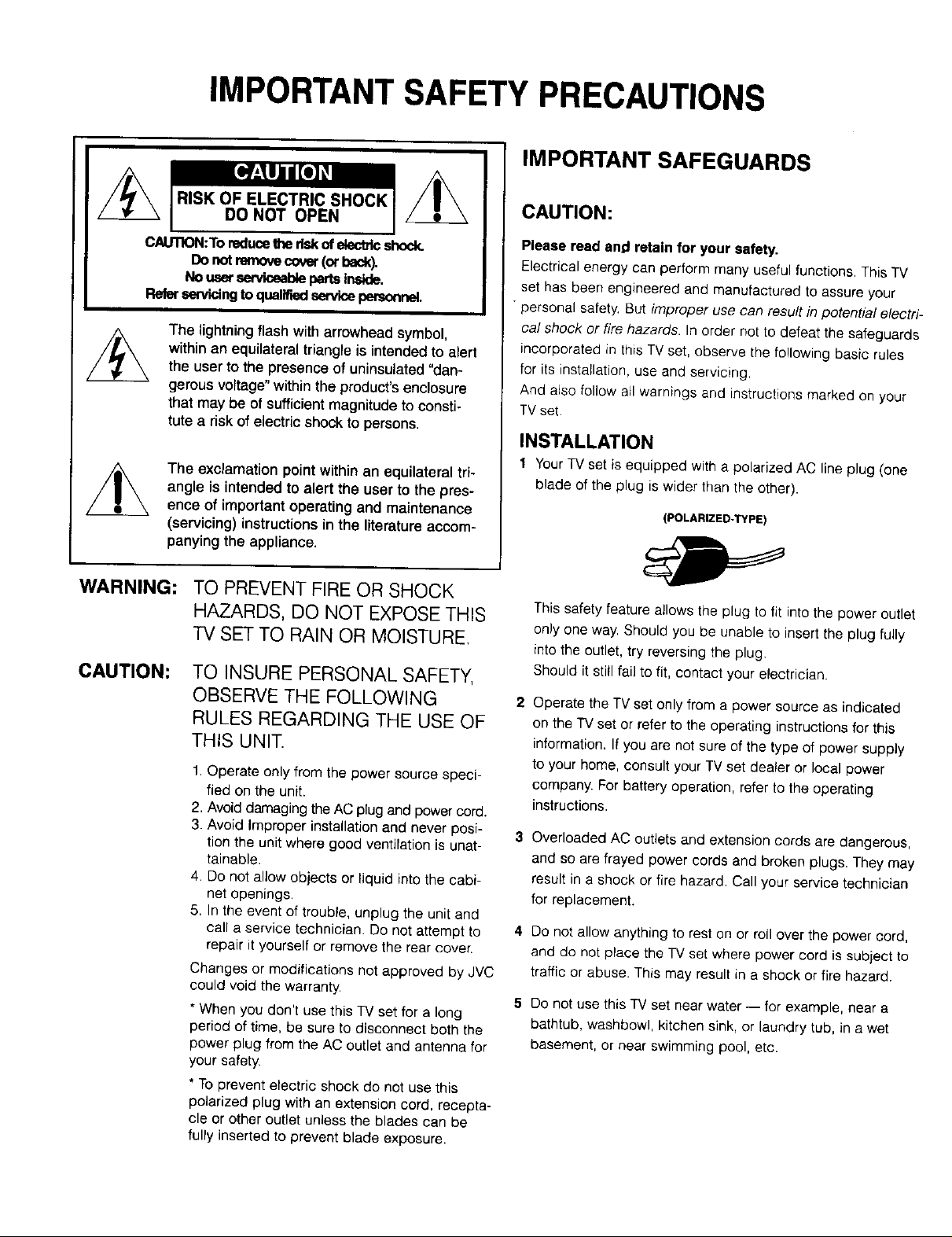
1 Your TV set is equipped with a polarized AC line plug (one
blade of the plug is wider than the other).
(POLARIZED-TYPE)
This safety feature allows the plug to fit into the power outlet
only one way. Should you be unable to insert the plug fully
into the outlet, try reversing the plug.
Should it sti_]fail to fit, contact your electrician.
Operate the TV set only from a power source as indicated
on the TV set or refer to the operating instructions for this
information. If you are not sure of the type of power supply
to your home, consult your TV set dealer or local power
company. For battery operation, refer to the operating
instructions.
Overloaded AC outlets and extension cords are dangerous,
and so are frayed power cords and broken plugs. They may
result in a shock or fire hazard. Call your service technician
for replacement.
Do not allow anything to rest on or roll over the power cord,
and do not place the TV set where power cord is subject to
traffic or abuse. This may result in a shock or fire hazard.
Do not use this TV set near water -- for example, near a
bathtub, washbowl, kitchen sink, or laundry tub, in a wet
basement, or near swimming pool, etc.
Page 3
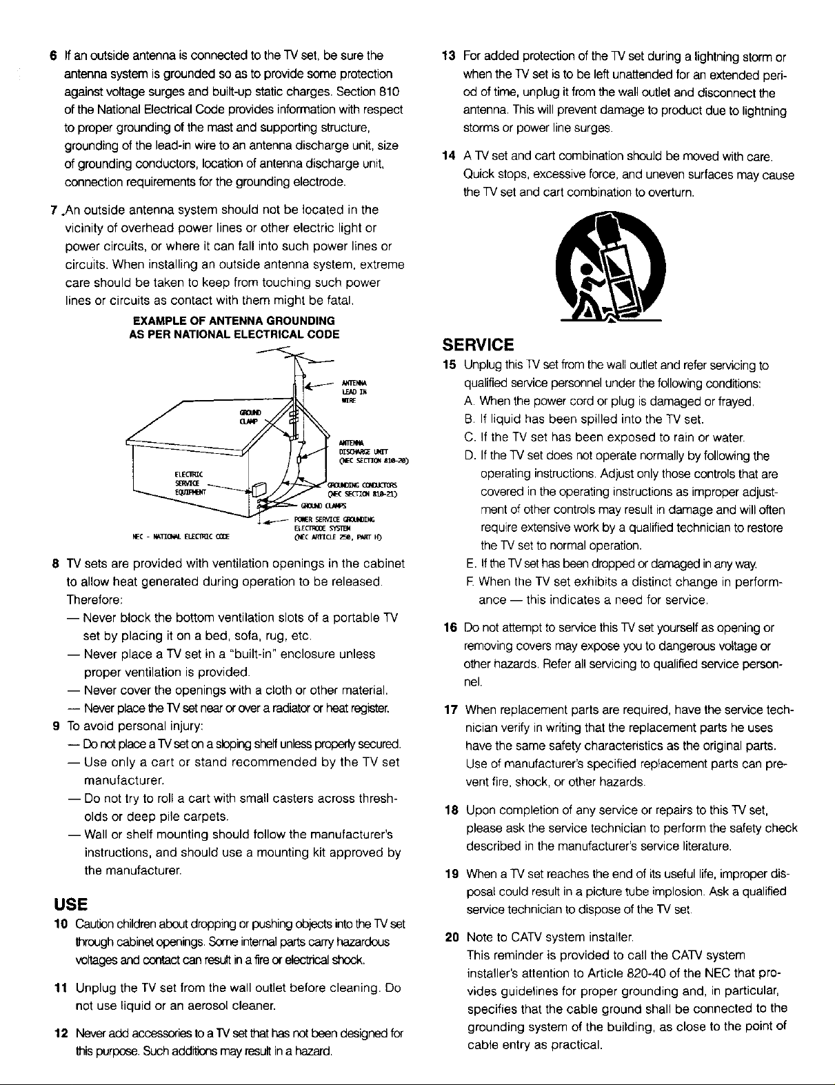
6 IfanoutsideantennaisconnectedtotheTVset,besurethe
antennasystemisgroundedsoastoprovidesomeprotection
againstvoltagesurgesandbuilt-upstaticcharges.Section810
oftheNationalElectricalCodeprovidesinformationwithrespect
topropergroundingofthemastandsupportingstructure,
groundingofthelead-inwiretoanantennadischargeunit,size
ofgroundingconductors,locationofantennadischargeunit,
connectionrequirementsforthegroundingelectrode.
7.Anoutsideantennasystemshouldnotbelocatedinthe
vicinity of overhead power lines or other electric light or
power circuits, or where it can fall into such power lines or
circuits. When installing an outside antenna system, extreme
care should be taken to keep from touching such power
lines or circuits as contact with them might be fatal.
EXAMPLE OF ANTENNA GROUNDING
AS PER NATIONALELECTRICAL CODE
kE_IM
(_C sEcri_ sle-ze)
_OU_ING _
NEC - N_I_O_L ELECI_C CODE _IEC _r_CLE _4J, FART H_
8 "IV sets are provided with ventilation openings in the cabinet
to allow heat generated during operation to be released.
Therefore:
-- Never block the bottom ventilation slots of a portable TV
set by placing it on a bed, sofa, rug, etc.
-- Never place a TV set in a "built-in" enclosure unless
proper ventilation is provided.
-- Never cover the openings with a cloth or other material.
-- Never place the W set near or over a radiator or heat register.
9 To avoid personal injury:
-- Do not place a'[V seton a sloping shelf unless properly secured.
-- Use only a cart or stand recommended by the TV set
manufacturer.
-- Do not try to roll a cart with small casters across thresh-
olds or deep pile carpets.
-- Wall or shelf mounting should follow the manufacturer's
instructions, and should use a mounting kit approved by
the manufacturer.
USE
10 Caution children about dropping or pushing objects intothe TVset
through cabinet openings, Some internal parts carry hazardous
voltages and contact nan resultin a fire or electrical shock.
11 Unplug the TV set from the wall outlet before cleaning. Do
not use liquid or an aerosol cleaner.
12 Neveradd accessories to arv set that has net been designed for
thispurpose. Such additbns may result in a hazard.
E_ _
13 For added protection of the TV set during a lightning storm or
when the TVset is to be left unattended for an extended peri-
od of time, unplug it from the wall outlet and disconnect the
antenna. This will prevent damage to product due to lightning
storms or power line surges.
14 A TV set and cart combination should be moved with care.
Quick stops, excessive force, and uneven surfaces may cause
the TV set and cart combination to overturn.
SERVICE
15 Unplug this 1_/set from the wall outlet and refer servicing to
qualified service personnel under the following conditions:
A. When the power cord or plug is damaged or frayed.
B. If liquid has been spilled into the TV set.
C. If the TV set has been exposed to rain or water.
D. If the TV set does not operate normally by following the
operating instructions. Adjust only those controls that are
covered inthe operating instructions as improper adjust-
ment of other controls may result in damage and will often
require extensive work by a qualified technician to restore
the TV set to normal operation.
E. ifthe TV sethas been dropped or damaged in any way
E When the TV set exhibits a distinct change in perform-
ance -- this indicates a need for service.
16
Do not attempt to service this TV set yourself as opening or
removing covers may expose you to dangerous voltage or
other hazards. Refer all servicing to qualified service person-
nel.
17
When replacement parts are required, have the service tech-
nician verify in writing that the replacement parts he uses
have the same safety characteristics as the original parts.
Use of manufacturer's specified replacement parts can pre-
vent fire, shock, or other hazards.
18 Upon completion of any service or repairs to this TV set,
please ask the service technician to perform the safety check
described in the manufacturer's service literature.
19 When a TV set reaches the end of its useful life, improper dis-
posa_could result in a picture tube implosion. Ask a qualified
service technician to dispose of the TV set.
2O
Note to CATV system installer.
This reminder is provided to call the CATV system
installer's attention to Article 820-40 of the NEC that pro-
vides guidelines for proper grounding and, in particular,
specifies that the cable ground shall be connected to the
grounding system of the building, as close to the point of
cable entry as practical.
Page 4
WELCOME!
Congratulations on your new television purchase! We thank you for choosing JVC.
We know you are anxious to start watching your new television, but before you operate it, please
read this guide and then keep it handy for future reference. After all you just bought a great TV with a lot
of terrific features, you should know what each feature is and how to use it properly!
Please note, as you read though this guide there are illustrations of select models for your
reference. There are several models covered in this guide and therefore each illustration may not be of
the specific model you own, Be sure to look for the similar feature on your TV.
Again, congratulations and thank you for choosing JVC! Enjoy!
TABLE OF CONTENTS
CONNECTIONS
Connections Checklist ............. 5
Panel Diagrams ................. 5
Cable and VCR Connections .......... 6
S-Video Connections .............. 6
Connecting to a DVD Player .......... 8
Connecting to an External Amplifier ...... 8
Connecting to JVC AV Compu Link
Capable Components ......... 9
Connecting to a Camcorder .......... 9
GETTING STARTED
Remote Controls ............... 10
Power ..................... 11
Adjusting Volume ............... 11
Changing Channels .............. 11
Remote Programming ............ 12
CATV & Satellite Codes ............ 12
VCR Codes .................. 13
MENU FUNCTIONS
Using the Menu ................ 14
Plug in Menu
Introduction .............. 15
Language ............... 15
Auto Tuner Setup ........... 15
Set Clock
Auto (XDS) ........... 16
Manual ............. 16
Finish ............... 16
Channel Summary ............... 17
V-Chip ..................... 18
Set Lock Code ............. 21
Picture Settings
Tint .................. 22
Color .................. 22
Picture ................. 22
Bright ................. 22
Detail ................. 22
Noise Muting ............. 22
Set Video Status ............ 22
Menu Functions (Continued)
Sound Settings
Bass .................. 23
Treble ................. 23
Balance ................ 23
MTS (Multi-channel TV Sound) .... 23
Some Sound Advice .......... 23
General Items
On/Off Timer .............. 24
TV Speaker .............. 25
Audio Out ............... 25
Component4n ............. 25
Closed Caption ............ 25
BUTTON FUNCTIONS
Menu ...................... 26
Exit ...................... 26
Display .................... 26
Video Status .................. 26
Sleep Timer .................. 26
Input ...................... 26
BBE ...................... 27
Hyper Surround ................ 27
Muting ..................... 27
Number Buttons (10 Key Pad) ........ 27
100+ ...................... 27
Return+ .................... 27
VCR Buttons .................. 27
Light .................... 27
PIP (Picture-In-Picture)
Introduction .............. 28
On/Move ............... 28
Freeze ................. 28
Swap .................. 28
Channel +/- .............. 28
Source ................. 28
APPENDICES
Troubleshooting ................ 29
Limited Warranty ............... 30
Authorized Service Centers .......... 31
Specifications ............ Back Cover
Page 5
Connections
CONNECTIONS CHECKLIST - READ ME FIRST
The Connections Checklist section of this guide is a list of ideas to keep in mind while you
setup your new TV. It is designed to help us not-so-technically-minded individuals make our
connections properly. If you read this section and still can't identify the plugs, connectors and
components you have, please ask someone for h_lp in making your connections.
1) Always refer to the connection instructions in the
user's guide for your components first. The
manufacturer will provide the most detailed
information about their products.
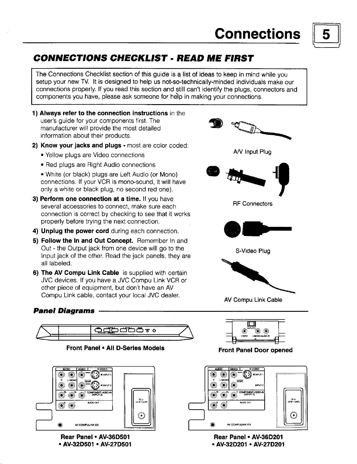
2) Know your jacks and plugs - most are color coded:
• Yellow plugs are Video connections
• Red plugs are Right Audio connections
• White (or black) plugs are Left Audio (or Mono)
connections. If your VCR is mono-sound, it will have
only a white or black plug, no second red one).
3) Perform one connection at a time. If you have
several accessories to connect, make sure each
connection is correct by checking to see that it works
properly before trying the next connection.
4) Unplug the power cord during each connection.
5) Follow the In and Out Concept. Remember In and
Out - the Output jack from one device will go to the
Input jack of the other. Read the jack panels, they are
all labeled.
6) The AM Compu Link Cable is supplied with certain
JVC devices. If you have a JVC Compu Link VCR or
other piece of equipment, but don't have an AV
Compu Link cable, contact your local JVC dealer.
I
A/V Input Plug
RF Connectors
S-Video Plug
AV Compu Link Cable
Panel Diagrams
Front Panel • All D-Series Models
® ®
® ®1®-
AVCOMPULbNK EX
Rear Panel • AV-36D501
• AV-32D501 • AV-27D501
II®
t,--------
F
Front Panel Door opened
(_ *,v COM_UNK EX
Rear Panel • AV-36D201
• AV-32D201 • AV-27D201
7S_
C_r _UHF)
®
Page 6
Connections
Cable and VCR Connections
There are three basic types of antenna or cable connections:
• If you have an antenna or have a cable system that does not require you use a cable box to
select channels, please refer to Diagram #1.
• If you have a cable system that requires the use of a cable box to access all the channels, please
refer to Diagram #2.
• If you have a cable system that requires the use of a cable box to access certain premium channels,
but not "basic" cable channels, please refer to Diagram #3.
• For instructions on connecting a VCR only, please see the Quick Setup Guide.
• For information on using Picture In Picture (PIP), please see page 28.
WALL
CABLEorANTENNA
O(/1"
TWO-WAY
SPLITTER
VCR
Yellow
White
Red
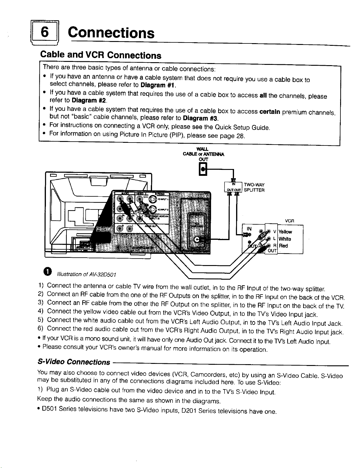
O Illustration of AV-32D501
1) Connect the antenna or cable TV wire from the wall outlet, in to the RF Input of the two-way splitter.
2) Connect an RF cable from the one of the RF Outputs on the splitter, in to the RF Input on the back of the VCR.
3) Connect an RF cable from the other the RF Output on the splitter, in to the RF Input on the back of the TV.
4) Connect the yellow video cable out from the VCR's Video Output, in to the TV's Video Input jack.
5) Connect the white audio cable out from the VCR's Left Audio Output, in to the TV's Left Audio Input Jack.
6) Connect the red audio cable out from the VCR's Right Audio Output, in to the TV's Right Audio Input jack.
• _fyour VCR is a mono sound unit, itwil_have only one Audio Out jack. Connect it to the TV's Left Audio Input.
• Please consult your VCR's owner's manual for more information on its operation.
S-Video Connections
You may also choose to connect video devices (VCR, Camcorders, etc) by using an S-Video Cable. S-Video
may be substituted in any of the connections diagrams included here. To use S-Video:
1) Plug an S-Video cable out from the video device and in to the TV's S-Video Input.
Keep the audio connections the same as shown in the diagrams.
• D501 Series televisions have two S-Video inputs, D201 Series televisions have one.
Page 7
Connections
Audio/Video Connections - Continued
CABLE
BOX
VCR
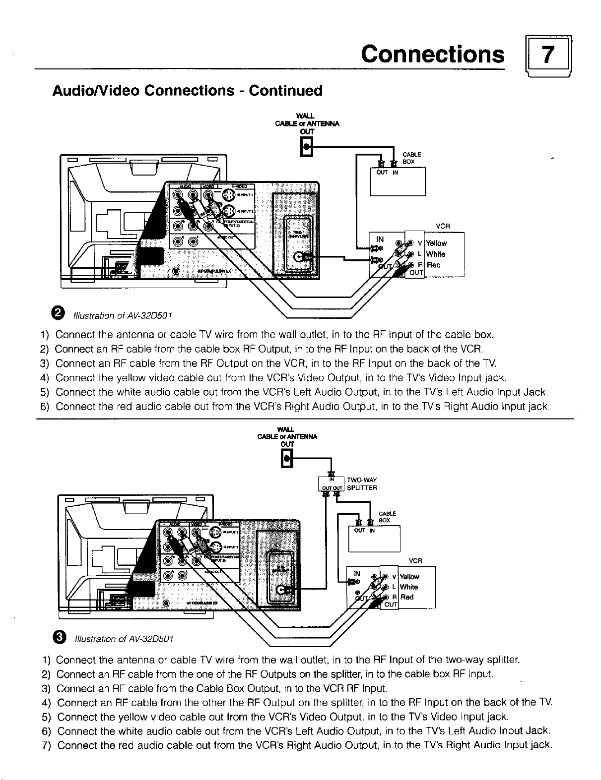
O Illustration of AV-32D501
1) Connect the antenna or cable TV wire from the wall outlet, in to the RF Input of the cable box.
2) Connect an RF cable from the cable box RF Output, in to the RF Input on the back of the VCR.
3) Connect an RF cable from the RF Output on the VCR, in to the RF Input on the back of the TV.
4) Connect the yellow video cable out from the VCR's Video Output, in to the TV's Video Input jack.
5) Connect the white audio cable out from the VCR's Left Audio Output, in to the TV's Left Audio Input Jack.
6) Connect the red audio cable out from the VCR's Right Audio Output, in to the TV's Right Audio Input jack.
CABLE ot _'_ri'ENNA
OUT
VCR
0 IllustrationofAV-32D501
1) Connect the antenna or cable TV wire from the wall outlet, in to the RF Input of the two-way splitter.
2) Connect an RF cable from the one of the RF Outputs on the splitter, in to the cable box RF Input.
3) Connect an RF cable from the Cable Box Output, in to the VCR RF Input.
4) Connect an RF cable from the other the RF Output on the splitter, in to the RF Input on the back of the TV.
5) Connect the yellow video cable out from the VCR's Video Output, in to the TV's Video Input jack.
6) Connect the white audio cable out from the VCR's Left Audio Output, in to the TV's Left Audio Input Jack.
7) Connect the red audio cable out from the VCR's Right Audio Output, in to the TV's Right Audio Input jack.
Page 8
Connections
Connecting to a DVD Player
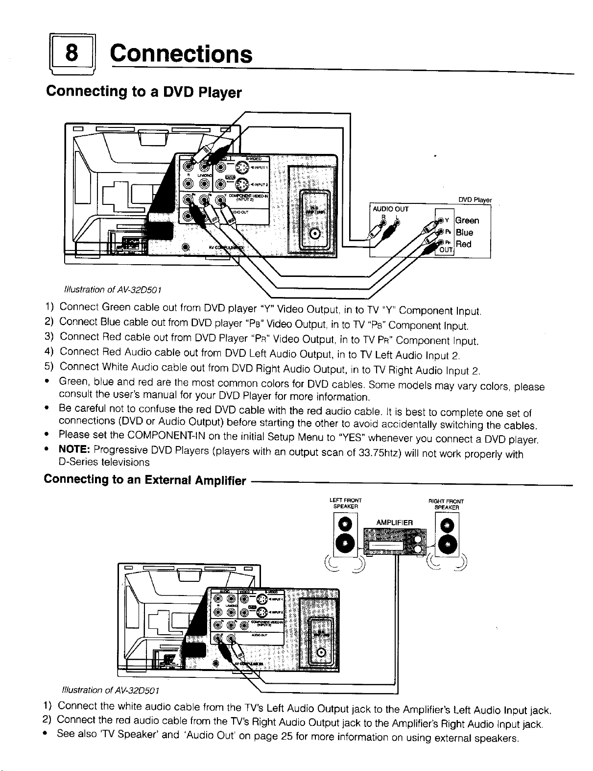
AUDIO OUT
R L
Illustration of A V-32D501
DVD Player
1) Connect Green cable out from DVD player "Y" Video Output, in to TV "Y" Component Input.
2) Connect Blue cable out from DVD player "Ps" Video Output, in to TV "Ps" Component Input.
3) Connect Red cable out from DVD Player "PR" Video Output, in to TV PR" Component Input.
4) Connect Red Audio cable out from DVD Left Audio Output, in to TV Left Audio Input 2.
5) Connect White Audio cable out from DVD Right Audio Output, in to TV Right Audio Input 2.
• Green, blue and red are the most common colors for DVD cables. Some models may vary colors, please
consult the user's manual for your DVD Prayer for more information.
• Be careful not to confuse the red DVD cable with the red audio cable. It is best to complete one set of
connections (DVD or Audio Output) before starting the other to avoid accidentally switching the cables.
• Please set the COMPONENT-IN on the initial Setup Menu to "YES" whenever you connect a DVD player.
• NOTE: Progressive DVD Players (players with an output scan of 33.75htz) will not work properly with
D-Series televisions
Connecting to an External Amplifier
LEFT FRONT RIGHT FRONT
SPEAKER SPEAKER
AMPLIFIER
Illustration of AV-32D501
1) Connect the white audio cable from the TV's Left Audio Output jack to the Amplifier's Left Audio Input jack.
2) Connect the red audio cable from the TV's Right Audio Output jack to the Amplifier's Right Audio Input jack.
• See also 'TV Speaker' and 'Audio Out' on page 25 for more information on using external speakers.
Page 9
Connections
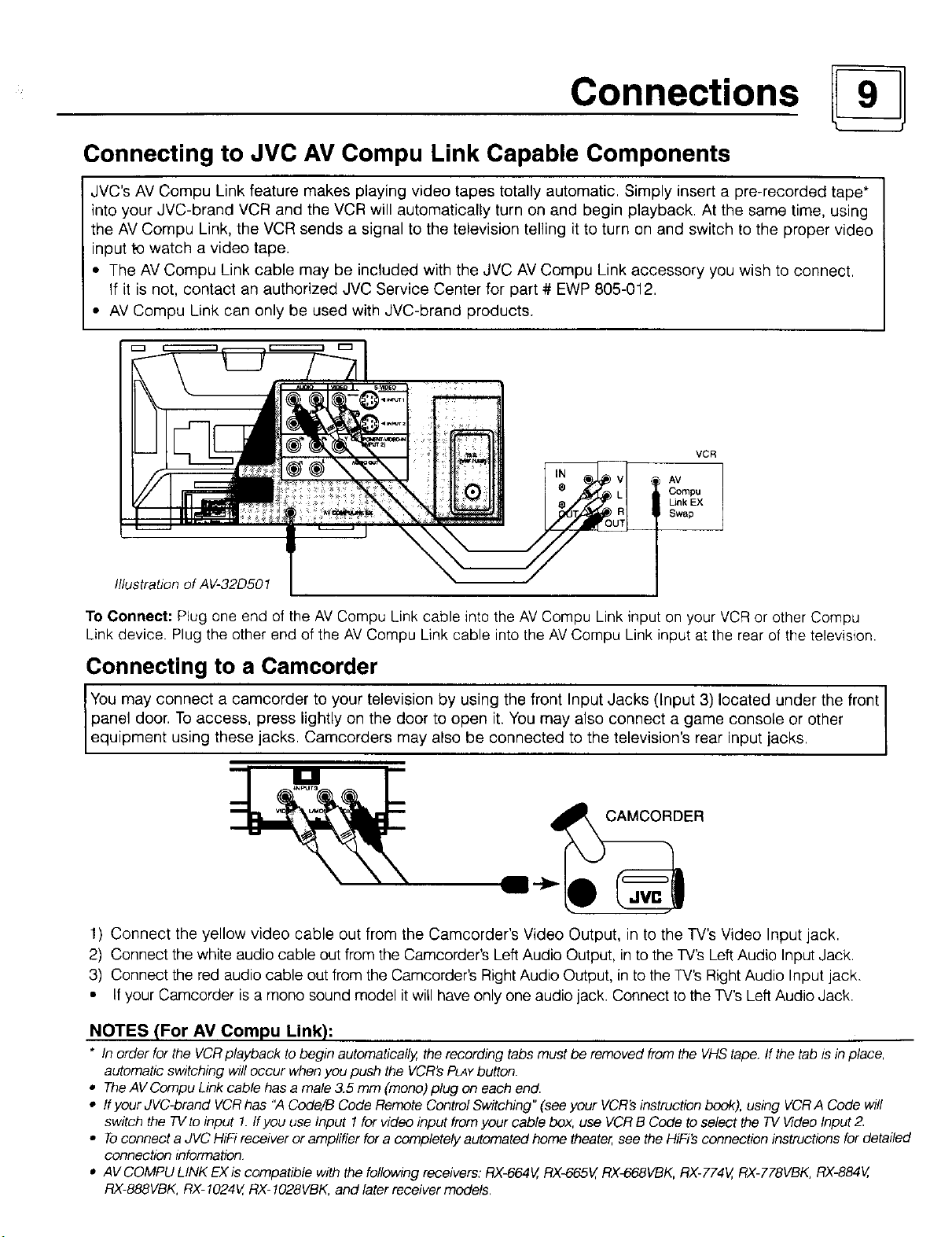
Connecting to JVC AV Compu Link Capable Components
JVC's AV Compu Link feature makes playing video tapes totally automatic. Simply insert a pre-recorded tape*
into your JVC-brand VCR and the VCR will automatically turn on and begin playback. At the same time, using
the AV Compu Link, the VCR sends a signal to the television telling it to turn on and switch to the proper video
input to watch a video tape.
• The AV Compu Link cable may be included with the JVC AV Compu Link accessory you wish to connect.
If it is not, contact an authorized JVC Service Center for part # EWP 805-012.
• AV Compu Link can only be used with JVC-brand products.
VCR
AV
Compu
Link EX
Swap
Illustration of AV-32D501
To Connect: Plug one end of the AVCompu Link cable into the AV Compu Link input on your VCR or other Compu
Link device. Plug the other end of the AV Compu Link cable into the AV Compu Link input at the rear of the television.
Connecting to a Camcorder
panel door. To access, press lightly on the door to open it. You may also connect a game console or other
IYou may connect a camcorder to your television by using the front Input Jacks (Input 3) located under the front
equipment using these jacks. Camcorders may also be connected to the television's rear input jacks.
CAMCORDER
!) Connect the yellow video cable out from the Camcorder's Video Output, in to the TV's Video Input jack.
2) Connect the white audio cable out from the Camcorder's Left Audio Output, in to the TV's Left Audio Input Jack.
3) Connect the red audio cable out from the Camcorder's Right Audio Output, in to the TV's Right Audio Input jack.
• If your Camcorder is a mono sound model it will have only one audio jack. Connect to the TV's Left Audio Jack.
NOTES (For AM Compu Link):
* In order for the VCRplayback tobegin automatically,therecordingtabs must be removedfromthe VHStape.If the tab isin place,
automaticswitchingwilloccur when youpush the VCR'sPLAYbutton.
• TheAVCompuLinkcable hasa male3.5 mm (mono)plug on eachend.
• If your JVC-brand VCRhas "A Code/B CodeRemote ControlSwitching"(see your VCR'sinstructionbook),using VCRA Code will
switch the TVtoinput 1.ffyouuse Input 1for video inputfromyour cable box, use VCRB Code toselect the TV VideoInput2.
• Toconnecta JVCHiFireceiveroramplifier fora completelyautomatedhometheater,seetheHiFi'sconnectioninstructionsfor detailed
connectioninformation
• AVCOMPULINK EXis compatible withthefollowingreceivers:RX4_64V,RX4_65V,RX-668VBK,RX-774V,RX-778VBK,RX-884V,
RX-888VBK,RX-1024V,RX-I028VBK,and laterreceivermodels.
Page 10
Getting Started
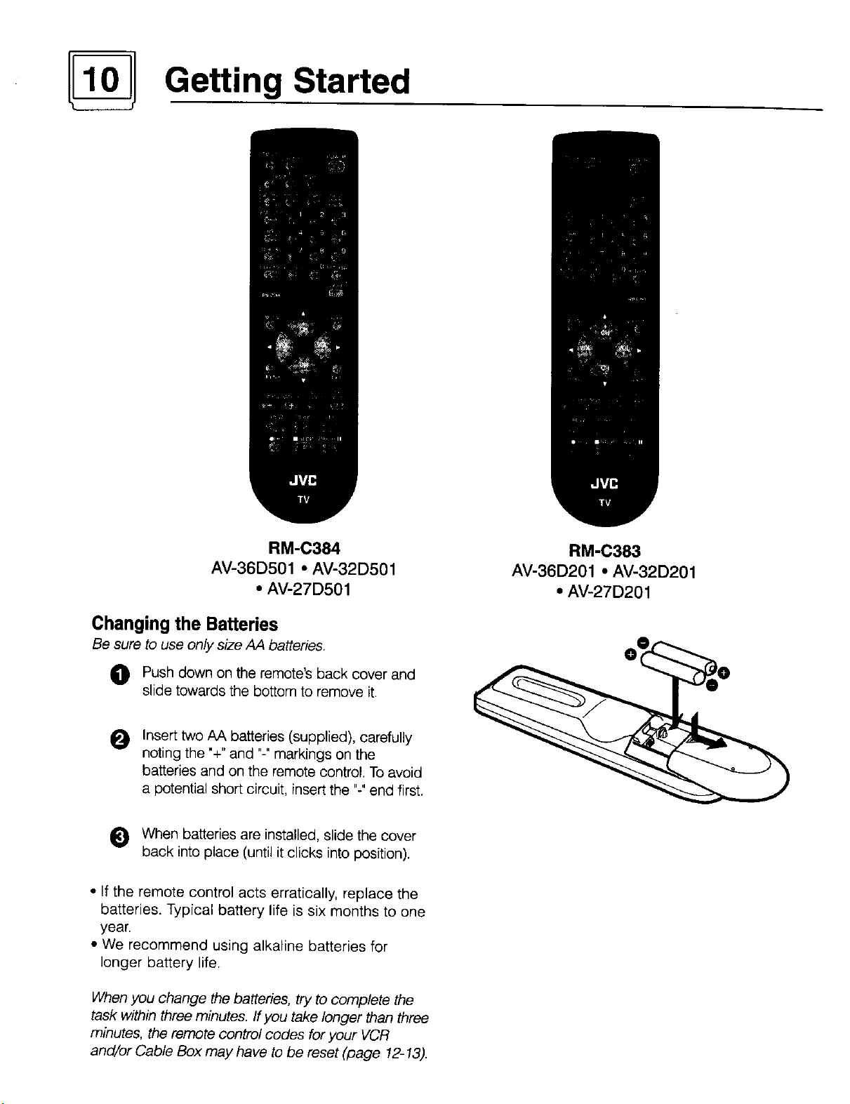
RM-C384
AV-36D501 • AV-32D501
• AV-27D501
Changing the Batteries
Be sure to use only size AA batteries.
Push down on the remote's back cover and
slide towards the bottom to remove it.
Insert two AA batteries (supplied), carefully
O
noting the "+" and "-" markings on the
batteries and on the remote control. To avoid
a potential short circuit, insert the "-"end first.
0 When batteries are installed, slide the cover
back into place (until it clicks into position).
• If the remote control acts erratically, replace the
batteries, Typical battery life is six months to one
year.
• We recommend using alkaline batteries for
longer battery life.
RM-C383
AV-36D201 • AV-32D201
• AV-27D201
When you change the batteries, try to complete the
task within three minutes. If you take longer than three
minutes, the remote control codes for your VCR
and/or Cable Box may have to be reset (page 12-13).
Page 11

Getting Started
POWER
• Press the POWERbutton on the remote control or the front panel of the TV. The On Timer lamp will glow red.
• Make sure the TV/CATV switch on the remote is set to TV. Move the switch to CATV only if you plan to operate
a cable box. Qn the CATV setting the remote will only operate the cable box functions.
• To turn the power off, press the POWERbutton again. The On Timer lamp will go out.
• The On Timer lamp will glow red when the On/Off Timer is set (page 26), even when the -iV power is off.
ADJUSTING VOLUME
To control the volume level, use the VOLUME+/- buttons on the remote control or on the TV's front panel. Use
the VOLUME* button to lower the volume. Press the VOLUME+button to raise the volume.
I VOLUME 13
Press the MUTINGbutton to instantly turn the volume to zero. Press MUTINGagain to return to the previous
volume level.
CHANGING CHANNELS
_) 10 key direct access
To move directly to a specific channel, press that channel's numbers on the remote's 10 key pad. For single-digit
channel numbers, press "0"then the channel number. For channels above 100, press the 100+ button, then the
remaining two digits on the 10 key pad.
O CHANNEL -/+ BU'I-rON
To scan through the channels, press either the CHANNEL+ or CHANNELo button. You will move through the
channels in numerical order.
• After you operate the Auto Tuner Setup (page 15), all of the empty channels will be removed from scanning.
When you scan you will only receive clear, active channels.
Hyperscan
With JVC's Hyperscan feature you can zip through the channels at a rate of five per second. To use Hyperscan,
press and hold either the CHANNEL+or CHANNEL-buttons. After the first few channels scan at normal speed, the
rest will move by at five per second. To scan at normal speed, press and release the CHANNEL+/-button.
Regular Return
Press and release the RETURN+button to return to the previous channel viewed. For example select a channel.
Then select another channel using the 10 key pad buttons. You can now flip back and forth between these two
channels by pressing RETURN+.
_]) RETURN+
With RETURN+YOUcan program your TV to always return to a specific channel. Press and hold down the RETURN+
button for three seconds. The message, "RETURN CHANNEL PROGRAMMED!" will appear on-screen. Now
when you scan through the channels, pressing RETURN+will bring you back to your programmed channel.
To cancel the RETURN+channel, press and hold the RETURN+button for three seconds. The message "RETURN
CHANNEL CANCELLEDF will appear on-screen.
• Pressing any number key or turning off the TV will also cancel the RETURN+channel.
Page 12

Remote Programming
Setting the CATV & VCR Codes
You can program your remote to operate your cable box or satellite receiver by using the instructions
and codes listed below. If the equipment does not respond to any of the codes listed below or to the
code search function, use the remote control supplied by the manufacturer.
Cable Box or Satellite setup
The remote control is programmed with CATV and/or Satellite codes for power on, power off, channel up,
channel down, and 10 key operation.
1) Find the CATV/Satellite brand from the list of codes shown below.
2) Slide the 2-way selector switch to "CATV".
3) Press and hold down the DISPLAYbutton.
4) With the DISPLAYbutton held down, enter the first code number listed using the 10 key pad.
5! Release the DLSPLAYbutton
6) Confirm the operation of the Cable Box/Satellite receiver.
• If your CATV or Satellite box does not respond to the first code, try the others listed. If it does not
respond to any code, try the Search Codes Function at the bottom of the page.
CABLE BOXES CODES CABLE BOXES CODES DIGITAL CODES
ABC 024 Puser 032 SYSTEMS
Archer 032,025 ,LRCA _ 061. 070 -
Cableview 051,032 Realistic 032 Echostar 100
Citizen 022, 561 -- Regal O58,-_)841(34010411042, 045, -- 106
Cur6s 058,O59 -- - 068 _rad]en e -- 117
Diamor_d 024,032, Q25 .... £4ger_cy _ _034__ _ _. -- .. Hitachi 104,111 " __
Eagre _ 029 ..... Rembrandt 037, 032, 051,£38 H_h_ 104 __
Eastern _ 034 .... SSarnsung 051 .... Panasonic 105
GCBrand _ 032, 051 _ Scientific A!lanta 057, 058,059 _ Philil3.s 102, 103
3#mini 022, 0.4_3 . _ SLMark 051, O,_7 . _ pnrnestar 108
3eneraqInstrument 065, 024, 025, 026, 027, 020, Sp[ucer 051, _056 _ _ RCA ..... 106, 109,. 110_
4amlin 040,Jl, 042, 045 Te!ecaption _ 0_67 __ __
4itach!_ _ 049,024 ...... Te!eview . 047_051 ....
Jerrold 065,024, 025, 026, 027, 020, Texscan 044
. 021, O22, 057,023 _ Tocorn. 035,,036, 066
Vlacom _ 049, 050, 051,()54 . toshiba _ 050 .......
k,lagnavox 033 . Jnika . __ 032,.025 _ .
Vlemorex 030 _ Iniversal 022,_032 .
_4ovietime 032 051 !ideoway _ 052....
_a_, 039,037,048 ,tiewstar 029,030
5anasonic O55, 5561660 -- Zenith - 063_,046 "
_aragon 063 . -Tenith/Drake 046 ....
3hilips 028, 029, 030, 052, 053, 031, Satellite
Pioneer 0471062
Pulsar 051,032
021,022, 057, 023 Stargate 032, 051
069
SATELLITE
107
Toshiba 101
Iniden 102,103
Search Codes Function:
1) Slide the 2-Way Mode Selector switch to CATV.
2) Press the TV POWERand RETURN+buttons. Hold for at least three seconds and release.
3) Press TV POWER, see if the CATV or Satellite box responds.
4) If there was a response, press RETURN+.The operating codes are now set. If there was no response,
repeat Step 3. If you repeat Step 3 64 times without a response, use the remote control which came
with the equipment.
Page 13

Remote Programming
VCR setup
The remote control is programmed with VCR codes for power on, power off, play, stop, fast-forward,
rewind, channel up, and channel down operation.
1) Find the VCR brand from the list of codes shown below.
2) Slide the 2-way selector switch to "TV".
3) Press and hold down the D_SPLAYbutton.
4) With the DISPLAYbutton held down, enter the first code number listed with the 10 key pad.
5) Release the D_SPLAYbutton.
6) Confirm the operation of the VCR.
• If your VCR does not respond to the first code, try the others listed. If it does not respond to any code,
try the Search Codes Function at the bottom of the page.
• Some manufacturer's VCR's may not respond to the TV/VCR button, even if other buttons work properly.
• To Record, hold down the RECbutton on the remote and press PLAY.
VCRs CODES VCRs CODES VCRs CODES
_,dmiral 035 _a_navgx £)31,023=024, 086 Samsung 037, 060, 062, 033, 089
_iwa 027,032 vlarantz 003, 004, 005 Sansui 003, 026, 020,052
_kaai" . 029, 072.073, 074 .... _rta ._ 964 _ San_,o 063, 067, 091,071
t_udio Dynamic . 003, 005 Vlemorex 024, 067
3eft & Howell 063, 071 rIGA 038, 040,047,048, 041,042
Broksonic 020, 026 _,tinolta 058, 045
5an0n O23] 055 _ubishi 938,O40. 6,47, 048, 04i, 0421
_,C.E 043 078, 090
3itizen 064 _luiiitech 047, 027, 062
3ra_ 063, 029, 064 NEC 003.004[ 0051 (300
Curtis Ma!hes 045, 024, 027, 093 Olyrnp!£ 024,023
Daewoo 043, 059, 024, 092 Optimus 028, 021,035, 064
DBX . ()%, 004,005 Orion 026, 020 V2000 027
Dimensia 045 P_Panasonic 023[ 024, 0211 022 Sylvania 031,023, 024, 027
Emerson 043, 026, 077, 061,025, 042, Penney 024, 058, 045, 063,003,004, Symphoniq 027,081
E_sh#r 063, 066, 067, 065, 071 Pentax 058,005, 045, 093 Tatuhg 003, 004, 005
Funai 027, 026, 020, 000 Philco 03!, 024, 027, 023, 026, 0201 Teac 003, O04, 027,005
GE 033,045,024, 093 043 Technics 021,022, 023,024
Go Video 037,051,049, 050, 089 Philips 031,023, 024, 086 Teknika 024, 027,070
Goldstar 064 Pioneer 023 Toshiba 059, 046, 079
Gradiente _ 083, 084, 081, OOO,001 -Proscan 045,058,023,024, 031,046, Vector Research 0(35
Hitachi 023, 045,058, 027, 081,093 .......... 059, 060, 033, 087, 093 __ Nards 035, 036, 067, 0441 064
Instant Replay 024, %3 Qqa§.a/ 021,022, 023, 024 famaha 063, 003, 004,005
Jensen 003 Radio Shack 033, 024, 063, 036, 067, 040, _Zenith 044, 062, 064
JVC OOO,001,002, 003, 004, 005 027
Kenwood 003, 004, 064, 005 RCA 033,045,058,023, 024103i,
LXl 027, 064, 058, 066, 066, 063, 046, 059, 060, 083, 085, 087,
020, 076 ........... 005, O93 Tashiro 064
067 093
Realistic 024, 063, 036, 067, 040, 027 m
Scott 059,060,062,067,038,040,
047,048,026,020
Sears 063, 064, 065,066, 058, 00O,
001
Shintom 075
Sh_i _ I)35:(336:08(31 088
#ignature 2000 027, (335
Singer 075
_9_Y 028, 029, 030, 053, 054, 055
!
Search Codes Function:
1) Slide the 2-Way Mode Selector switch to TV.
2) Press the VCR POWERand RETURN+buttons. Hold for at least three seconds and release.
3) Press VCR POWER, see if the VCR responds.
4) If there was a response, press RETURN+.The operating codes are now set. If there was no response,
repeat Step 3. If you repeat Step 3 74 times without a response, use the manufacturers remote control
which came with the VCR.
Page 14

Using the Menu
Using this Guide
Certain symbols are used throughout this guide to help you learn about
the features of your new television. The ones you will see most fre-
quently are:
AY Up and Down arrows mean press the CHANNELUP or CHANNEL
DOWN buttons. Pressing the UP or Dow_ buttons let you:
• Move vertically in a main menu screen
• Move through a submenu screen
• Move to the next letter, number, or other choice in a submenu
• Back up to correct an error
• Scan through TVchannels (when not in a menu screen)
• • Left and right arrows mean press the VOLUMELEFTor VOLUME
RIGHTbuttons to:
• Select a high#ghted menu item
• Select an item in a submenu
• Select numbers in certain menu options
• Turnthe volume up or down (when not in a menu screen)
The "Press Button" icon means you should press the button named on
your remote control. (Button names appear in SMALLCAPn-ALLETTERS.)
The 'Helping Hand' points to the highlighted or selected item in a
menu.
The Onscreen Menus-
To bring up the onscreen menu, press the MENUbutton on the
remote control The item that appears in yellow is the one currently
selected. If you press the MENUbutton again, the onscreen display will
skip to the next menu screen.
Menu Screen Order _ 2 _ 4 ---_ 5 _ 6 -_
The "Plug In Menu' will appear the first time the TV is plugged in.
Notes: Menus shown in this book are illustrations, not exact replications of the
television's onscreen displays.
Ifyou use the Menu button on the TV'sfront panel instead of the remote, an additional
menu screen showing channel number and input will appear between menus I and 2.
PLUG IN MENU _l:=l:}-,
[_ LANGUAGE ENG FRE SPA
AUTO TUNER SETUP
SET CLOCK
Picture Settings
PICTUREADJUST v
[] PREVIOUS
[_TINT ..............Dr........
COLOR ..............D.........
PICTURE .............. _..........
BRIGHT ,=_,=_4],=,_
DETAIL .............._...........
[] NEXT PAGE
SELECT BY r'Ji'1i_l
OPERATE BY l_']rk-'lEXITBY
PICTUREAD3UST m am
0
[] PREVIOUS
CiNois MU'nNG ON OPE
SETVIDEO STATUS
[] NEXT PAGE
SELECT BY r,&ll_-1 D
OPERATE BY l_Ir_l EXITBY_
_) Sound Settings
SOUND AD3UST v
[] PREVIOUS
[_ BASS
TREBLE
BALANCE
MTS STEREO SAP MONO
[] NEXT PAGE
SELECT BY r"i[1i_1
OPERATE By IW'_Ik'I
0 General Items
CLOCK/TIMERS
[] PREVIOUS
_SET CLOCK
ON/OPETIMER
mill
EXITBY_D
FINISH
SELECT BY []I@'I ,i""""'_
OPERATE BY l'_lrR EXITBY W
0 Initial Setup Items
INITIALSETUP
[] PREVIOUS
[_ AUTO TUNER SETUP
CHANNEL SUMMARY
V-CHIP
SET LOCKCODE
I"@1NEXTPAGE
SELECT BY _] I'_"1
OPERATE BY I'_ I'b-"l
[] NEXT PAGE
SELECT BY l'il[] d'_,
OPERATE BY I"_IIR EXITBY q7
m m
,, 0
E
EXITBYe OPERATE BY I"_II'FI EXIT
INITIALSETUP _ am
[] PREVIOUS
[_ TV SPEAKER ON OFF BB
AUDIO OUT VARI FIX
COMPONENT-IN YES NO
LANGUAGE ENG FRE SPA
CLOSEDCAPTION
[] NEXT PAGE
SELECT BY [_[] BYe
v
Page 15

Plug In Menu
Introduction
The Plug In Menu comes up automatically when
you first turn on the TV after plugging it in. The
Plug In Menu helps you to get your TV ready to
use by letting you set your preferences for:
• The Language in which you want the onscreen
menus _ appeag
• The Auto Tuner Setup of which channels you
wish to receive,
• Setting the TV's clock to the correct time so
your timer functions will work properly
Descriptions of each of the Plug In Menu features
appear on this page and the next. We recommend
you complete the Plug In Menu setup first so your
TV is set up just the way you want, right away
Language
You can choose to view your onscreen menus in
three languages: English, Spanish, or French.
Press the MENUbutton
AV To LANGUAGE
Auto Tuner Setup
In Auto Tuner Setup, the TVautomatically scans
through all available channels, memorizing the active
ones and skipping over blank ones or channels with
weak signals. This means when you scan (using the
CHANNEL 4-/- buttons) you will receive only clear,
active channels,
Press the MENUbutton
AV ToAUTO TUNER SETUP
• • To operate
AIR
I TUNER MODE : CABLE
• • To choose CABLEor AIR
J,Y To move to START
• • To start Auto Tuner Setup
START
NOW
PROGRAMMING !
PPP_ PPP
48
411_ To choose a language
ENGLISH _ FRENCH _SPANISH _]
EXIT when finished
NOTES:
If you exit the Plug In Menu, or wish to change your preferences later, all the Plug In Menu options can be found in the
regular onscreen menus.
Programming will take approximately 1 to 2
minutes.
1 PROGRAMMING OVER, 1
• Noise Muting will not work during Auto Tuner
Setup.
Page 16

__ Plug In Menu
Set Clock
Before you use any of your TV's timer functions,
you must first set the clock. You may precisely set
your clock using the XDS time signal broadcast
by most Pubfic Broadcasting stations. To set the
clock using the XDS signal:
Enter the channel number of your local PBS
station.
Press MENU
AV To Set Clock
• • To operate
• • ToAuto
MODE AUTO MANUAL
TIMEZONE EASTERN
D.S.T. ON OFF
FINISH
&y To Tine Zone
• • To select your time zone
Set Clock. Manual
To set your clock manually (without using the XDS
signal), choose MANUAL from the Set Clock menu
and follow the steps below.
MODE AUTO MANUAL
TIME --:....
STARTCLOCK
&, To move to the hour
• • To set the hour
Ay To move to minutes
• • To set the minutes
&V To move to START CLOCK
• • To start clock and exit
I
THANK YOU !!
I
Finish
_1_ ATLANTIC '<-_,EASTERN '<-_ C ENTRAL'<-_, MOUNTAIN <_
_ HAWAII,4_IJ- ALASKA '4_1_ PACIFIC < .J
kV To move to Daylight Savings Time (O.S.T )
• • ToturnD.S.TONorOFF
AV To FINISH
• • To save settings and exit
• If you do not have a PBS station in your local
area, you will have to set the clock manually See
'Set Clock - Manual' at the top of the next column
for instructions.
• The Daylight Savings Time feature automatically
adjusts your TV's clock for Daylight Savings. The
clock will move forward one hour at 2:00 am on
the first Sunday in April. The clock will move back
one hour at 2:00 am on the last Sunday in
October
NOTES:
Once you have the items in the Plug In Menu set
to your personal preferences, move to the Finish
option to save your settings.
AY 7-oFINISH
• • To save settings and exit
• You can change the preferences you set in the
Plug In Menu at any time using the regular JVC
onscreen menu system.
You will have to reset the clock after a power interruption of 90 seconds or Ionge_ You must set the clock before operating
any timer functions
Page 17

Plug In Menu
Channel Summary
Channel Summary allows you to customize the
line-up of channels received by your 73/ You can
add or delete channels from the line-up or
prevent any unauthorized viewers from watching
any or all 181 channels.
Press the
&V To CHANNEL SUMMARY
• • To operate
The Channel Summary screen (below) will now
be displayed with the channels set to scan
marked with an ",/". You can delete channels
from the scan by removing the ",/". If any
channels were missed during Auto Tuner Setup
and you wish to add them, you may by placing
an ",/" next to the channel numbe_
OlVa
01
02
03
04
05
MENUbutton
v
,/
,/
,/
06 ./
07
08
09 ./
10 v
Channel Summary. Lock
&V ToCHANNEL SUMMARY
• • Tooperate
&V To the Lock Column
ZERO to lock or unlock that channel
01 ,/
02 v"
03 v"
04 ,/
05 ,¢
EXITwhen finished
Channel Guard Message
When a viewer attempts to watch a guarded channel,
the following message appears.
THISCHANNELISLOCKEDBY
CHANNEL GUARD.
PLEASEENTERLOCK CODE BY
10 KEYPADTOUNLOCK I£
06 v"
07
o8
09 €"
10 '/"
NO. - . . -
AY To the SCAN column
• • To include or delete from scan
EXITwhen finished
Towatch a channel that you have locked, enter the
Lock Code using the 10 keypad (see "Set Lock
Code" - at the top of the next column).
If the wrong code is entered, this message will flash
on the screen:
INVALIDLOCKCODE ! I
The channel cannot be accessed until the correct
code is entered.
• Once a channel has been unlocked, it will
remain unlocked until the television is turned off.
NOTES:
Some cable systems experience interference from radio frequencies on cable Channel 95. Youmay delete this channel
from your scan by removing the next to It on the Channel Summary screen.
Page 18

V-Chip
V.Chip
Your TV is equipped with V-Chip technology which
enables TV Parental Guideline and Movie (MPAA)
Guideline controls. V-Chip technology allows you to
program your TV to receive, or not to receive,
programs based on content accoFding to the
guidelines. Programs which exceed the ratings limits
you set will be blocked.
When a viewer attempts to watch a blocked channel,
this message appears:
THISPROGRAMMING EXCEEDS
YOUR RATINGSLIMITS.
PLEASEENTERLOCK CODE BY
10 KEY PAD TO UNLOCK IT.
NO.----
To watch a blocked channel, enter the lock code
(page 14) using the 10 key pad
To set up the TV Parental Guideline
Ratings:
Press the MENUbutton
AY To V-CHIP
• • To operate (Lock icon _ will appear)
Press ZERO to access the V-Chip menu
V-CHIP ON OFF
SETUS TV RATINGS
SETI_OVIERATINGS
UNRATED VIEW BLOCK
FINISH
• • To turn V-Chip ON or OFF
&Y Tomove to SET US TV RATINGS
• • To operate (see page 19 for details)
BBBBBm
V/FV
S
L
D
FINISH
U.S. PARENTAL RATING SYSTEMS
Programs with the following Ratings
are appropriate for Children.
[]
TVY is Appropriate for All Children.
Programs are created for very young viewers
and should be suitable for all ages, including
children ages 2 - 6.
TVY7 is for Older Children.
[]
Most parents would find such programs
suitable for children 7 and above. They may
contain some mild fantasy violence or
comedic violence, which children should be
able to discern from reality
Programs with the following Ratings
are designed for the entire audience.
[] TV G stands for General Audience.
Most parents would find these programs
suitable for all age groups. They contain tittle
or no violence, no strong language, and little
or no sexual dialog or situations.
[3 TV PG Parental Guidance Suggested.
May contain some, but not much, strong
language, limited violence, and some
suggestive sexual dialog or situations. It is
recommended that parents watch these
programs first, or with their children.
"IV 14 Parents Strongly Cautioned.
Programs contain some material that may be
unsuitable for children under the age of 14
including possible intense violence, sexual
situations, strong coarse language, or
intensely suggestive dialog. Parents are
cautioned against unattended viewing by
children under 14.
TV MA Mature Audiences Only.
These programs are specifically for adults
and may be unsuitable for anyone under 17
years of age. TV MA programs may have
extensive V, S, L, or D.
Viewing Guidelines
• V/FV is for VIOLENCE/FANTASY VIOLENCE
• S stands for SEXUAL CONTENT
• I stands for strong LANGUAGE
• D stands for suggestive DIALOG
Page 19

V-Chip
Directions to Block Viewing:
Line up the cursor in the column (TV PG, TV G,
etc.) with the content row (V/FV, S, etc.) and press
the AorY to move the cursor to the correct
location. Press • or • to turn the locking feature
on or off. An item is locked if the I_1 icon
appears instead of a "--".
For example. To block viewing of all TV 14
shows:
Move the cursor to the top row of that column
and add a lock icon. Once you've put a lock on
the top row, everything in that column is
automatically locked.
AV To the TV 14 Column
• • To turn on the lock
BBWBWm
-2
v/w - _ - -
D II --
FINISH
&V To FINISH
Directions to set up Movie Ratings:
Press the MENU button
AV To V-CHIP
• • To operate (Lock icon I_1appears)
Press ZEROto access V-Chip setup
options
AV To SET MOVIE RATINGS
• • To enter movies menu
X NC-17R PGt3 PG G NR
FINISH
[] NR - Not Rated.
This is a film which has no rating. In many
cases these films were imported from countries
which do not use the MPAA ratings system.
Other NR films may be from amateur producers
who didn't intend to have their film widely
released.
NR (Not Rated) Programming may contain
all types of programming including
children's programming, foreign programs,
or adult material.
• • To save settings and exit
• If you want to change the setup, move the
cursor to the top column and change the lock
icon to "--". You may then select individual
categories to block.
Special Note about Ratings
Some programs are not broadcast with a
ratings signal. Therefore, even if you setup
V-Chip ratings limits, these programs will
not be blocked. Parents are cautioned to
preview the contents of these programs or
movies.
NOTE (For Canadian Viewers):
V-Chipfunctionis based on specifications for the United States and therefore may not work properly in Canada.
G - General Audience.
In the opinion of the review board, these
films contain nothing in the way of sexual
content, violence, or language that would be
unsuitable for audiences of any age.
[_ PG - Parental Guidance.
Parental Guidance means the movie may
contain some contents such as mild violence,
some brief nudity, and strong language. The
contents are not deemed intense.
£1 PG-13 - Parents Strongly Cautioned.
Parents with children under 13 are cautioned
that the content of movies with this rating
may include more explicit sexual, language,
and violence content than movies rated PG.
Page 20

I -0-]l V-Oh ip
[] R Restricted.
These films contain material that is explicit in
nature and is not recommended for
unsupervised children under the age of 17.
[3 NC-17 No One Under 17.
These movies contain content which most
parents would feel is too adult for their children
to vie_z Content can consist of strong language,
nudity, violence, and suggestive or explicit
subject matter
C] X No One under 18.
Inappropriate material for anyone under 18.
Directions to Block Movie Viewing:
To block viewers from any or all of these ratings
categories, press the • orV to move the cursor
to the correct location. Press the • or •
buttons to turn the locking feature on or off. An
item is blocked if the _ icon appears instead of
a "_".
Notes About Unrated Programs:
Unrated programming refers to any
programming which does not contain a rating
signal. Programming on television stations
which do not broadcast rating signals will be
placed in the "Unrated Programming" category.
Examples of Unrated programs:
Emergency Bulletins
Locally Originated Programming
News
Pofitical Programs
Public Service Announcements
Religious Programs
Sports
Weather
Some Commercials
• TVprograms or movies that do not have rating
signals will be blocked if the Unrated
Category is set to LOCK.
For example, to block viewing of X and NC-17
rated from shows.
&V To the X Column
• • To turn on the lock
x NC-17R PG13 PG G NR
/i
FINCH
• V To the NC- 17 Column
• • To turn on the lock
x Nc-17R PG13PG G NR
it It
FINISH
• V To FINISH
• • To save settings and exit
Directions to Block Unrated Programs:
You can block programs that are not rated.
12 Press the MENU button
• V To V-CHIP
• • To operate
_) Press ZERO to access V-Chip setup
• V To UNRATED
<•
12
options
To View or Block
UNRATED VIEW BLOCK
Press EXIT when done
NOTES:
In order for V-Chip settings to take effect, V-Chip settings must be turned ON in the V-Chip menu (page 18).
You can automatically unblock all of your restrictions by turning V-Chip settings OFF in the V-Chip menu (page 18).
You can always unblock a restriction by re-entering the V-Chip menu and removing the lock icon.
Page 21

V-Chip
Accessing V.Chip Information:
To access Rating information about a certain
program, press the V-CHIP button while viewing
that program. A display like this will appear:
" I_1 PROGRAMIS]I/-p6RATED-V: I
If you decide you want to block this category of
viewing, press "0" while the above screen is
visible, and all programs from that category will
be blocked.
Example 1:
If you want to set your V-Chip settings to block
all programming above TV PG:
(_ Press ZERO when TV-PG is
displayed
."8 -
s
l mmimml I
D a
22
° For Children's programming you can block
TV-Y and Y programs by Pressing "0" when Y is
displayed during a program. Programming for
audiences other than children's audiences will
not be affected.
Set Lock Code
Channel Guard and V-Chip settings are protected
by a four-digit Lock Code. Your TV comes pre-set
with a Lock Code of "0000". You may change the
code to any four-digit number you wish. To
change the Lock Code, follow the steps below
I_ Press the MENUbutton
&V To SET LOCK CODE
• • To operate
It
The padlock icon appears
(_ Press ZEROto access the Lock Code
I
LOCKCODE 0000 I
FINISH
I
All Programming above TV PG will be
blocked.
Example 2:
If you want to set your V-Chip settings to block
all programming above a current setting such
as TV PG-V (with violence):
I_) Press ZERO when TV-PG - V is displayed
BBWBWW
• • To select the number
AV To move to the next digit
Continue to follow these directions for all four
,IV To FINISH
• • To save settings and exit
Your Lock Code is new set.
v/_v Ii _ a -
s
L
D
All Programming above TV PG with
Violence will be blocked!
NOTES:
• After a power interruption you must reset the Look Code.
• Write your Lock Code number down and keep it hidden from potential viewers.
• If you forget the Lock Code, a new code may be set using the steps listed above.
The first digit will be highlighted
numbers
Page 22

Picture Settings
Tint
Tint allows you to adjust the levels of red and green in
your TV picture.
AV To TINT
• To increase the levels of green
• To increase the levels of red
h,V To move to the next setting
Color
The color function lets you make all the colors in the
TVpicture appear either more vivid or subtle.
AV To COLOR
• To make the colors more vivid
• To make the colors more subdued
AV To move to the next setting
Picture
Picture allows you to adjust the levels of black and
white on the TV screen, giving you a darker or
brighter picture overall.
Noise Muting
This feature inserts a blank blue screen over
channels which are not broadcasting or are too
weak to be received clearly
_) Press the MENUbutton
AV TONOISE MUTING
• • To turn Noise Muting ON or OFF
• Noise Muting will not work during Auto Tuner
Setup or when you operate Channel Summary
Set Video Status
With Set Video Status, you can save your own set
of picture quafity adjustments as "Choice" and
have access to them at the touch eTa button.
_) Press the MENUbutton
Ay To SET VIDEO STATUS
• • To operate
&V To PICTURE
• To increase the level of contrast
• To decrease the level of contrast
AV To move to the next setting
Bright
You can adjust the overall brightness of the TV
picture with the Bright control.
A_t' To BRIGHT
• To lighten the picture
• To darken the picture
Ay To move to the next setting
Detail
The Detail feature adjusts the level of fine detail
displayed in the picture.
AV ToDETAIL
• Tomake the picture sharper (more details)
• Tomake the picture smoother (less detail)
&V To move to the next setting
TINT
COLOR
PICTURE _====_
BRIGHT _==_
DETAIL
SAVEAS CHOICE
• • To set the TINT levels
AV To move to the next option
Repeat these steps until all levels are seL
AV To SAVE AS CHOICE
• • To save settings and exit
• You must use SAVE AS CHOICE to exit the Set
Video Status menu, otherwise your preferences
will net be saved.
• You can access your "Choice" settings at any
time by pressing the VtOEOSTATUSbutton on the
remote control.
NOTES:
The setting screen will disappear if you do not make any adjustments or move to the next setting in approximately three
seconds Any changes you have made to picture settings up to that point will be stored. You can exit the Picture Settings
menu at any time by pressing the EXITbutton on the remote control.
Page 23

Sound Settings
Bass
You can increase or decrease the level of
low-frequency sound in the TV's audio with the
Bass adjustment.
(_ Press the MENUbutton
&y To BASS
• To increase the bass
• To decrease the bass
AV To move to the next setting
Treble
Use Trebletoadjust the level of high-frequency
sound in your TV'saudio.
I_ Press the MENUbutton
&V To TREBLE
• To increase the treble
• To decrease the treble
&V To move to the next setting
Balance
Adjust the level of sound between the TV's two
speakers with the Balance setting.
MTS (Multi.Channel Television Sound)
MTS technology allows several audio signals to be
broadcast at once, giving you a choice in what
you wish to hear with a TV program. In addition to
mono or stereo sound, an MTS broadcast may
also include a Second Audio Program (SAP).
_) Press the MENUbutton
&V To MTS
I
MTS STEREO SAP MONO I
ONAIR_
I
• • Select the mode
(The ON AIR arrow tells you if a broadcast
is in Stereo and/or contains an SAP).
• Keep the TV in STEREO mode to get the best
sound quality. The sound will work in STEREO
mode even if a certain broadcast is in MONO
sound only.
• Choose the MONO setting to reduce excessive
noise on a certain channel or broadcast.
• Selecting SAP will allow you to hear an
alternative soundtrack, if one is available.
(_) Press the MENUbutton
&V To BALANCE
• To shift the balance towards the right
speaker
• To shift the balance towards the left
speaker
Ay To move to the next setting
NOTES:
Some Sound Advice
You can tell if a program is broadcast in stereo
by the position of the ON AIR arrow in the MTS
menu screen. Unfortunately, while many
programs are originally broadcast in stereo,
some cable companies may "squash" the
transmission to mono sound because they have
only mono equipment. If you are connected to a
cable system, the sound quality is determined
by the cable company. If they broadcast only in
mono, you will receive only mono sound, even if
the program was aired in stereo.
Fortunately, most stereo programs are
broadcast by the major television networks. If
you connect an antenna to your TV instead of
cable and set the tuner mode in Auto Tuner
Setup to "Air" instead of "Cable" you will be
able to pick up stereo broadcasts in their
original stereo format
You can leave the Sound Settings menu at any #me by pressing the EXITbutton on the remote control.
Page 24

General Items
On/Off Timer
The On/Off timer lets you program your television
to turn itself on or off. You can use it as an alarm
to wake up, to help you remember important
programs, or as a decoy when you're not home.
(_) Press the MENUbutton
&• To ON/OFF TIMER
• • To operate (begins with ON TIME)
ON TIME 7:00PM
OFF TIME 10:00PM
CHANNEL 02
MODE ONCE EVERYDAY
ON/OFFTIMER YES NO
FINISH
• • To set the hour (AM/PM) you want the TV
to turn on
• To move to minutes
• • To set the minutes
D501 Timer Note:
If the television is on when a timed event is about
to start a Timer Preview window will appear. The
Timer Preview window will appear in the lower right
corner of the screen seven seconds before the
timer is programmed to begin. When the timer
activates, the Preview picture will become the main
picture.
33
O__
Seven seconds before Timer
Activates ....
33
• To accept ©N TIME and move to OFF
TIME (the time the TV will turn off). Set the
OFF TIME the same way as QN TIME
• To accept OFF TIME and move to
CHANNEL
• • To select channel
• To move to MODE
• • Choose ONCE or EVERYDAY
• To ON/OFF TIMER
• • Choose YES to accept the timer setting,
choose NO if you don't wish to accept
• To FINISH
• • To save settings
Timer
Actva_
f
(Preview of ON/OFF Timed
Program)
Seven seconds later...
4
•
Timer Activates
NOTES:
On/Off Timer cannot be set to locked or guarded channels. In order for the On/Off Timer to work, the clock must be set. After
a power interruption Timer settings must be reset.
Page 25

General Items
TV Speaker
If your 7q/_ connected to a stereo system, you can
turn off the TV speakers and listen to the audio
through your stereo.
Press the MENUbutton
&Y To TV SPEAKER
ON OFF
J TVSPEAKER
• • To turn the TV's speakers ON or OFF
_) EXITwhen finished
• Before you turn the TV Speaker setting from OFF to
ON, make sure that theTV volume level is Iowl ff
the TV volume is set too high, the sound level will be
extremely loud.
• After a power interruption, the TV Speaker settings
will return to "ON".
Audio Out
If your television is connected to an external
speaker source, Audio Out gives you the option of
controlling the volume level with your TV's remote
control.
Press the MENUbutton
Component.In
Get the best quality video from your DVD player
by using this setting and the DVD inputs at the
rear of the television. Set Video-2 either to YES for
component input (for DVD) or to NO for composite .
video input (for a regular VCR).
Press the MENUbutton
&V To COMPONENT-IN
I CONPONENT-IN YES
TOturn the input ON or OFF
EXIT when finished
• This option should be used with DVDplayers
only For information on connecting VCR's see
page 6. For more information on connecting a
DVD player, see page 8.
NO
I
Closed Caption
Use this function to display the Closed Captioning
text onscreen (when included in a broadcast).
Press the MENUbutton
AV To CLOSED CAPTION
• • To operate
&Y
• • To VARIorFIX
VARh Lets you adjust the volume of the external
speakers using the VOLUME+/- buttons on your
TV's remote control.
FIX: The volume of the external speakers is
adjusted using the audio device's remote control.
To AUDIO OUT
AUDIOOUT _RI
EXITwhen finished
...... •
FiX
&T
AY
NODE : CAPTION
CAPTION : CC1 CC2 CC3 CC4
TEXT : T1 T2 T3 T4
FINISH
To select CAPTION, TEXT, or OFF
To CAPTION or TEXT
To select a caption (CC1 to CC4) or text
channel (T1 to T4)
Toaccept that selection and move to
FINISH
Tosave settings and exit
NOTES:
Closed Captions subtitles are usually found on caption channel CC1. Some programs may include additional text
information which is usually found on text channel T1. The other channels are available for future use.
Closed captioning may not work correctly if the signal being received is weak or ff you are playing a video tape.
Most broadcasts containing Closed Captioning will display a notice at the start of the program.
External Speakers: When using external speakers or amplifiers, shut off the TV Speakers (see 'TV Speakers') above.
Page 26

Button Functions
Menu
The MENUbutton allows you to access JVC's
onscreen menu system. Press MENUto activate the
onscreen menu system.
• See individual topics (like "Sound Settings) for
specific information on using menus.
Exit
Press the EXITbutton to leave a menu screen or to
turn off the PIP feature (page 28).
Display
TheDisplay screen shows the current status of timers
and inputs,
(_ Pressthe DISPLAYbutton
07
NOW 12:20PM
SLEEPTIMER OFF
ON/OFFTIMER EVERYDAY
OH TIME 7:00PM
OFF TIME 10:00PM
Video Status
The VIDEOSTATUSbutton gives you a choice of
three TV picture display settings, including a
display of your own preferences.
Standard - Resets the 15icture display to the
factory settings.
Choice - Displays the setting levels you specified
on the "Set Video Status" Menu (see page 22).
Theater - Gives a rich, film-like look to video.
(_ Press the V_DEoSTATUSbutton
_" CHOICE_ THEATER--'-* STANDARD_]
Sleep Timer
The Sleep Timer can turn the TV off for you after you
fall asleep. Program it to work in intervals of 15
minutes, for a total time of up to 180 minutes.
(_ the SLEEPTIMERbutton
Press
• The channel or AV input (Channel 07)
• The current time (12:20 pm)
• Sleep Timer status/minutes remaining
(The Sleep Timer is off)
• On/Off Timer status (Set to turn on
everyday at 7:00 PM, off at 10:00 PM)
• Each Press of the DISPLAYbutton
changes the display mode:
Display-_ Time _ Channel-_ Off
Display - Full screen shown above Input
Time - Shows the current time only
Channel - Shows the current channel
Off - Turns Display off
• You may also turn off the Display at any step by (_
pressingEXIT.
You then have 20 seconds to press the S_eepTimer
button to delay the shutoff for another 15 minutes.
Selects the signal input source for the television:
TV (for Antenna or Cable) or Video 1, 2, or 3 for
video devices like VCR's or camcorders.
I
0 15 30 45 60 75 90 105 120 135 150 !65 180 _Pj
Sleep Timer Message
20 seconds before the automatic shutoff, this
message will appear:
GoooNIGHm I
PUSH SLEEPTIMERBUTTON
I
TV -_VIDEO-1 _ VIDEO-2 ---_VIDEO-3 _]
TO EXTEND.
INPUT
NOTES:
Please note that if the Clock, Sleep Timer or On/Off Timer are not set, the Display screen will show: "Clock Not Set',
"Sleep Timer OFF; and "On/Off Timer Off" respectively
Page 27

Button Functions
BBE
BBE high definition audio adds natural, clear and
extrardinary sound quality to any program. Turn
BBE On or Off using the BBE button.
BBE ON OFF
Hyper Surround
Creates a deep, three-dimensional sound effect
by channeling the audio through the TV's
front-firing speakers. Press the HYPERSURROUND
button to turn the effect on or off
I HYPERSURROUND ON OFF
Muting
The MUTINGbutton instantly turns the volume down
completely when you press it.
(_ MUTING
The volume level will instantly go to zero,
• To restore the volume to its previous level, press
MUTINGagain.
Number Buttons. 10 Key Pad
Tomove directly to a specific channel, enter the
channel number with the number buttons on the
remote. For example, to move to Channel Z
Return+
The RETURN+button has two functions."
Return - Returns to the channel viewed just
before the channel currently onscreen.
Return+ - Lets you program a specific channel to
return to while scanning through the channels.
(_ RETURN+and hold for three seconds
RETURNCHANNEL
PROGRAHHED!
Scan using the Channel+/- buttons
RETURN+
You will return to your programmed
channel.
• To cancel your Return+ channel, press and hold
the RETURN+button for three seconds. The
message "RETURN CHANNEL CANCELLED!" will
appear.
• Return+ works only with CHANNEL+/-. Pressing
any number key will cancel Return+.
• Return+ does not effect the PIP channel.
• For more information on Return and Return+,
turn to page 11.
VCR Buttons
I
I_ O(zero)
(_D 7 (seven)
100+ Button
Use the 100+ button to directly access channels
above Channel 99. For example to move to channel
124."
(_) 100+
(_ 2 (two)
_ 4 (four)
You can use this remote control to operate the
basic functions of your VCR. These functions
include: play, record, rewind, fast-forward, stop,
pause, channel scan, TV/ VCR, power on, and
power off.
• The remote is preset with the code 000 to control
JVC-brand VCR's. For any other manufacturer's
brand VCR, please see the code chart and
instructions on page 13.
Light (D501 Models Only)
The RM-384 remote includes illuminated buttons for
key features like CHANNEL+/- and VOLUME+/-. Press
the LIGHTbutton to turn the illumination on.
I_ LIGHT
NOTES:
BBE is a registered trademark of BBE Sound, Inc. For U,S., licensed from BBE Sound, Inc. under USP 4638258, 4482866
and 5510572. For Canada, licensed from BBE Sound, Inc. BBE is a registered trademark of BBE Sound, Inc.
Page 28

Button Functions - PIP
PIP (Picture.In-Picture)
PIP displays two separate pictures on screen.
Your D-Series television has 2-Tuner PIP, meaning
you can view pictures from two different channels
simultaneously. A special set of PIP control buttons
are located on the upper part of the remote
control. Descriptions of each button appear on this
page.
Note: PIP is available on model D501 Series
sets only.
ON/MOVE
Turn PIP on by pressing the ON/MOVE button.
(_ (PIP) ON/MOvE
07
02
FREEZE
Use the FREEZEbutton to lock a single, still image
onto the PIP window
(_ FREEZE
• If PIP is off when FREEZEis pressed, a snapshot
of the main screen is taken and placed in the
PIP window.
• If PIP is on when FREEZEiS pressed, the image
in the window when the button was pressed is
held.
SWAP
You can exchange the channel displayed on the
main screen for the one shown in the PIP window
by pressing SWAR
(_ SWAP
CHANNEL +/- For PIP
Like the main CHANNEL+/- buttons, CHANNEL4-l-
for PiP lets you scan through the channels in the
PIP window.
(_ EXITto turn PIP off
Once PIP is turned on, you can move the PIP
window to any of the TV's main picture's four
corners with the ON/MOVE button.
(_ ON/MOVE
t
• Each press of ON/MOvE will shift the PIP window
to a different corner.
NOTES:
(_ CHANNEL +/-
• Direct channel selection with the 10 key pad for
PIP is not possible.
SOURCE
You can select the signal source for the PIP
window image.
(_ SOURCE
i-, v-1--,.v.2--.v-3
• If the PIP does not have a signal, the window
will be blue.
• If you connect a DVD to Video-2, the PIP
window will be blue.
• In order for PIP to work, the television must be set to "TVmode". If you play a videotape, your TV will switch to "VCR
mode ". The TV only sees one signal in VCR mode. In order to use PIP,press the INPUTbutton to return to TV Mode.
• The PIP window is 1/9the size of the full screen.
• PIP will not display blocked channels or programs. A blue screen will display instead.
Page 29

Troubleshooting
There is no power • See if the power cord became unplugged.
• Check for a blown fuse or circuit breaker or a power outage.
There is no picture • The antenna could be disconnected. -
or sound • The input mode (TV/ Video) could be set improperly. See page 26.
• The tuner (Auto Tuner Setup) could be set improperly. See page 15.
• The TV station may be having difficulties. Check to see if other stations are working.
Remote control is not ,, Check to see that the batteries are still working and properly installed.
operating properly or • Make sure the remote has a clear sight path to the TV.
at all ,,Check that the TV/CATVswitch is in the proper position (RM-383/RM-384 only).
You cannot select a • Youmay be too far from the TV.Youmust be within 23feet (7 meters).
certain channel • Make sure the channels have been programmed. See "Channel Summary", page 17.
• Check to see if the channel is locked. See "Channel Summary - Lock" page 17.
The power turns off • Make sure the set did not become unplugged.
by itself • Perhaps the On/Off Timer is set. See page 24.
• Check to see if the Sleep Timer was set. See page 26.
The clock is wrong • The power was interrupted and the clock was not reset. See page 16.
The On Timer is • There is a problem with the TV. Unplug the set and call for service
blinking
The color quality • Tint and Color may be improperly adjusted. See page 22.
is poor • The Video Status mode may be turned to the wrong setting. See page 26.
There are lines • There could be interference from another electrical appliance, such as a computer,
across the picture another TVor VCR. Move any such appliances further away from the TV.
The picture is spotted • There could be interference from a high-wattage appliance, like a hairdryer or vacuum,
operating nearby. Move the antenna away from the appliance or change to a coaxial
cable connection which is less prone to interference.
There are double • A building or passing airplane can reflect the original signal and produce a second,
pictures (ghosts) slightly delayed one. Adjust your antenna position.
Picture is snowy • Your antenna may be damaged, disconnected or turned. Check the antenna
(image noise) connection page 6 and inyour Quick Setup Guide. If the antenna is damaged, replace it.
Screen is 80% black • The Closed Caption Textmode is on. Turn it off in the Closed Caption Menu, page 25.
Stereo or bilingual • Make sure the MTS settings are correct. See "MTS"on page 23.
programs can't be
heard
There is no sound • The TV Speaker option may be turned off. See page 25.
from the TV's speakers
Static electricity • It is normal to feel static electricity if you brush or touch the screen.
You hear occasional • It is normal for the TV to make crackling sounds when first turned on or off. Unless
crackling sounds the sound or picture become abnormal, this is fine.
Page 30

Limited Warranty
JVl
For Canadian model televisions, see separate sheets for Warranty/Garantie and
JVC Authorized Service Centers in Canada,
JVC COMPANY OF AMERICA warrants this product and all parts thereof, except as set forth below ONLY TO THE ORIGINAL PURCHASER AT RETAIL
to be FREE FROM DEFECTIVE MATERIALS AND WORKMANSHIP from the date of original retail purchase for the period shown below (the "Warranty
Period") (PICTURE TUBE is covered for Two (2) years.)
" Parts ILabor ]
I 1YEAR I 1YEAR I
THIS LIMITED WARRANTY IS VALID ONLY IN THE FIFTY (50) UNITED STATES, THE DISTRICT OF COLUMBIA AND COMMONWEALTH OF
PUERTO RICO.
WHAT WE WILL DO:
If this product is found to be defective within the warranty period, JVC will repair or replace defective parts at no charge to the
original owner. Such repair and replacement services shall be rendered by JVC during regular buslnese hours at JVC authorized
service centers. Parts used for replacement are warranted only for the remainder of this Warranty Period. All products and parts
thereof may be brought to a JVC authorized service center on a carry-in basis. Televisions with a screen size of 25 inches and larger may be
covered on an in-home basis where such service is available.
WHAT YOU MUST DO FOR WARRANTY SERVICE:
To determine if in-home service is available in your area, either contact the selling dealer (retailer) or call 1-800-537-5722 to locate the nearest JVC
authorized service center. Service locations can also be obtained from our website httD:/h/,'ww.ivcservice.com. In-home service, if available, will require
clear access to the Television by the service representatives. If in-home service is not available, carry in service willbe provided.
f service is not locally available, box the product carefully, preferably in its original carton, and ship, Insured, with s copy of your bill of sale
31us a letter of explanation of the problem to the nearest JVC Factory Service Center, the name and location which will be given to you by
:he toll free number.
If you have any questions concerning your JVC Product, please contact our Customer Relations Department.
WHAT IS NOT COVERED:
This limited warranty provided by JVC does not cover:
1)Preducta which have been subject to abuse, accident, alteration, modlflcetlon, tampering, negligence, misuse, faulty
installation, lack of reasonable care, or if repaired or serviced by anyone other than a service facility authorized by JVC to
render such service, or if affixed to any attachment not provided with the products, or If the model or serial number has been altered
tampered with, defaced or removed;
2) Initial installation, installation and removal from "built-in" entertainment centers and other mounting systems;
3) Operational adjustments covered in the Owner's Manual, normal maintenance, video and audio head cleaning;
4) Damage that occurs in shipment, due to an act of God, and cosmetic damage;
5) Signal reception problems and failures due to line power surge;
6) Video Pick-up Tubes/CCD Image Sensor, Cartridge, Stylus (Needle) are covered for 90 days from the date of purchase;
7) Accessories;
8) Batteries (except that Rechargeable Batteries are covered for 90 days from date of purchase.)
There are no express warranties except as listed above,
THE DURATION OF ANY IMPLIED WARRANTIES, INCLUDING THE IMPLIED WARRANTY OF MERCHANTABILTY, IS LIMITED TO THE
DURATION OF THE EXPRESS WARRANTY HEREIN.
JVC SHALL NOT BE LIABLE FORTHE LOSS OF USE OFTHE PRODUCT, INCONVENIENCE, OR ANY OTHER DAMAGES, WHETHER DIRECT,
INCIDENTAL OR CONSEQUENTIAL (INCLUDING, WITHOUT LIMITATION, DAMAGE TO TAPES, RECORDS OR DISCS) RESULTING FROM THE
USE OF THIS PRODUCT, OR ARISING OUT OF ANY BREACH OF THIS WARRANTY, ALL EXPRESS AND IMPLIED WARRANTIES, INCLUDING
THE WARRANTIES OF MERCHANTABILITY AND FITNESS FOR PARTICULAR PURPOSE, ARE LIMITED TO THE WARRANTY PERIOD SET
FORTH ABOVE.
;ome states do not allow the exclusion of incidental or consequential damages or limitations on how long the warranty lasts, so these
exclusions or limitations may not apply to you. This warranty gives you specific legal rights and you may also have other rights which vary
state to state.
JVC COMPANY OF AMERICA 1700 Valley Road
DIVISION OF JVC AMERICAS CORP. Wayne, New Jersey 07470
htto://www.ivcservice.com
REFURBISHED PRODUCTS CARRY A SEPARATE WARRANTY. THIS WARRANTY DOES NOT APPLY FOR DETAILS OF
REFURBISHED PRODUCT WARRANTY. PLEASE REFER TO THE REFURBISHED PRODUCT WARRANTY INFORMATION
PACKAGED WITH EACH REFURBISHED PRODUCT.
For customer use:
Enterbelow the Model No.and Serial No. which Is located either on the rear, bottom or side of the cabinet.
Retainthis information for future reference.
Model No.: Serial No.:
Purchase Date: Name Of Dealer:
Page 31

Authorized Service Centers
ooA,, JVC SERV,OE
HOW TO LOCATE YOUR JVC SERVICE CENTER
TOLL FREE: 1 (800) 537-5722
Dear Customer; http://www'jvceervlce'c°m
In order to receive the most satisfaction from your purchase, read the instruction booklet before operating the uniL In the
event that repair is necessary, or for the address nearest your location, please refer to the factory service center list below
or within the Continental United States, carl 1-800-537-5722 foryour authorized servicer Remember to retain your Bill of
Sale for Warranty Service.
-- JVC
JVC SERVICE & ENGINEERING
COMPANY OF AMERICA
DIVISION OF JVC AMERICAS CORP
Dear customer;
FACTORY SERVICE CENTER LOCATIONS
In order to receive the most satisfaction from your purchase, read this guide before operating the unit, and before calling for
service make sure you check the Troubleshooting pages at the end of this book. In the event that repair is necessary, or for
the address nearest you, please refer to the factory service center list below, or within the continental United States, call the
toll free number above for an authorized service center. Remember to retain your bill of sale for warranty service.
10 New Maple Avenue
Pine Brook, NJ 07058-9641
(973) 396-1000
5665 Corporate Avenue
Cypress, CA 90630-0024
(714) 229-8011
13 Cummings Park
Woburn, MA 01801
(781) 376-9100
Sophisticated electronic products may require occasional service. Just as quality is a keyword in the engineering and
production of the wide array of JVC products, service is key to maintaining the high level of performance for which JVC
is world famous. The JVC service and engineering organization stands behind our products.
JVC SERVICE & ENGINEERING COMPANY OF AMERICA
1500 Lakes Parkway
Lawrenceville, GA 30243-5857
(770)339-2582
2969 Mapunapuna Place
Honolulu, HI 96819-2040
(808) 833-5828
8192 State Road 84
Davie, FL 33324
(954) 472-1960
NATIONAL HEADQUARTERS
DIVISION OF JVC AMERICAS CORP.
1700 Valley Road
Wayne, New Jersey 07470
705 Enterprise Street
Aurora, lL 60504-8149
(630) 851-7855
10700 Hammerly Suite 110
Houston, TX 77043
(713) 935-9331
890 Dubuque Avenue
South San F_ncisco, CA 94080-1804
(650) 871-2666
IF YOU SHIP THE PRODUCT
Pack your JVC unit in the original carton or one of equivalent
size and strength. Enclose, with the unit, a letter stating the
problem or symptom that exists and also a copy of the receipt or
bill of sale you received when you purchased your JVC unit. Print
your home return address on the outside and inside of the
carton, Send to the appropriate JVC Factory Service Center as
listed above.
Topurchase accessories for your JVC product, you may contact your local JVC Deale_ Or from the
48 Continental United States call toll free : 1(800) 882-2345
ACCESSORIES I
Don't service it yourself
CAUTION
Toprevent electrical shock, do not open the
cabineL No user serviceable parts inside.
Refer to qualified service personnel.
Page 32

Specifications
MODEL
ReceptionFormat
ReceptionRange
Power
Consumption
PowerSource
ScreenSize
AudioOutput
Speakers
AntennaTerminal
AV-36DS01
133W/1.9A 130W/1.9A 133W/ 1.9A 128W/ 1.8A 123W/1.8A 118W/1.7A
36 inch/ 90om
measureddiagonally
AV-36D201 AV-320501 AV-32D201 AV-27D501
NTSC,BTSCSystem(Multi-ChannelSound)
VHF2to 13, UHF14to 69
SubMid, Mid, Super,HyperandUltrabands
(181channelfrequencysynthesizersystem)
AC120V,60Hz
32 inch/ 80 cm
measureddiagonally
full square
2x3 1/2/5x 12cm ovalx2
75ohms(VHF/UHF)terminal(F-typeconnector)
full square
5.0W+ 5.0W
AV-27D201
27inch/ 68cm
measureddiagonally
full square
ExternalInput
Jacks
S-VideoInput
Jacks
ComponentInput
Jacks
AudioOutput
Jacks(VARI/FIX)
AVCompuLink
EXJack
Dimensions(In)
WxHxD(cm)
Weight(Ibs/ kg) 149.6/ 68 114.4/ 52.0 78.1/ 35.5
Accessoires Remotecontrolunit/ AAbatteriesx 2
Specifications subject to change without notice.
37 7/8"x 30 1/2"x 24 1/2"
96.2x 77.3x 62,1
FIX:500mVrms(-4dBs)Low impedance(400 Hzwhenmodulated100%)
Audio:500 mVrms(-4dBs),high impediance
Y:lVp-p positive,75 ohms(negativesyncprovided)
Y:lVp-p positive,75 ohms(negativesyncprovided)
VARI:Morethan0to 1550mVrms(+6dBs),
Video:1 Vp-p,75ohms
C:0.286Vp-p(burstsignal),75ohms
PB/PR:0.7Vp-p,75ohms
3.5 mmminijackx 1
33 7/8'x 27"x 215/8"
85.9x68.4x 54.8
29 5/8'x 23 1/4' x19 1/2'
75.2x 59.0x49.4
JVC COMPANY OF AMERICA
Division of JVC Americas Corp.
1700 Valley Road
Wayne, New Jersey, 07470
JVC CANADA, INC.
21 Finchdene Square
Scarborough, Ontario
Canada, M1X 1A7
O CTOS66-OO1A-A
1299-TN-JII-JIM
 Loading...