

Page 1
6
3
0
SERVICE MANUAL
COLOR TELEVISION
AV-36360
AV-36330
AV-36S36
/M /R
AV-36S33
/M /R
/M /R
/M /R
AV-36360 AV-36S3
AV-36330 AV-36S3
AV-3632
BASIC CHASSIS
GE
AV-36320
[RM-C254]
AV-36 360
AV - 36 S36
[RM-C255]
AV-36 330
AV - 36 S33
[RM-C205]
AV-36 320
CONTENTS
/M /R
!
SPECIFICATIONS
!
SAFETY PRECAUT IONS ・・・・・・・・・・・・・・・・・・・・・・・・・・・・・・・・
! FEATU RES・・・・・・・・・・・・・・・・・・・・・・・・・・・・・・・・
!
FUN CTIONS
!
MAIN DIFFERENCE LIST ・・・・・・・・・・・・・・・・・・・・・・・・・・・・・・・・
! HOW TO INDENTIFY MODELS ・・・・・・・・・・・・・・・・・・・・・・・・・・・・・・・・
!
SPECIFIC SERVICE INSTRUCTIONS
!
SERVICE ADJUSTMENTS ・・・・・・・・・・・・・・・・・・・・・・・・・・・・・・・・
! PARTS LIST ・・・・・・・・・・・・・・・・・・・・・・・・・・・・・・・・
★ STAND ARD CIRCUIT DIAGRAM ・・・・・・・・・・・・・・・・・・・・・・・・・・・・・・・・
1
・・・・・・・・・・・・・・・・・・・・・・・・・・・・・・・・・・・・・・・・・・・・・・・・・・・・・・・・・・・・・・・・
・・・・・・・・・・・・・・・・・・・・・・・・・・・・・・・・・・・・・・・・・・・・・・・・・・・・・・・・・・・・・・・・
・・・・・・・・・・・・・・・・・・・・・・・・・・・・・・・・
・・・・・・・・・・・・・・・・・・・・・・・・・・・・・・・・・・・・・・・・・・・・・・・・・・・・・・・・・・・・・・・・
・・・・・・・・・・・・・・・・・・・・・・・・・・・・・・・・・・・・・・・・・・・・・・・・・・・・・・・・・・・・・・・・
・・・・・・・・・・・・・・・・・・・・・・・・・・・・・・・・・・・・・・・・・・・・・・・・・・・・・・・・・・・・・・・・
・・・・・・・・・・・・・・・・・・・・・・・・・・・・・・・・・・・・・・・・・・・・・・・・・・・・・・・・・・・・・・・・
・・・・・・・・・・・・・・・・・・・・・・・・・・・・・・・・・・・・・・・・・・・・
・・・・・・・・・・・・・・・・・・・・・・・・・・・・・・・・・・・・・・・・・・・・・・・・・・・・・・・・・・・・・・・・
・・・・・・・・・・・・・・・・・・・・・・・・・・・・・・・・
・・・・・・・・・・・・・・・・・・・・・・・・・・・・・・・・・・・・・・・・・・・・・・・・・・・・・・・・・・・・・・・・
・・・・・・・・・・・・・・・・・・・・・・・・・・・・・・・・・・・・・・・・・・・・・・・・・・・・・・・・・・・・・・・・
・・・・・・・・・・・・・・・・・・・・・・・・・・・・・・・・・・・・・・・・・・・・・・・・・・・・・・・・・・・・・・・・
・・・・・・・・・・・・・・・・・・・・・・・・・・・・・・・・・・・・・・・・・・・・・・・・・・・・・・・・・・・・・・・・
・・・・・・・・・・・・・・・・・・・・・・・・・・・・・・・・・・・・・・・・・・・・・・・・・・・・・・・・・・・・
・・・・・・・・・・・・・・・・・・・・・・・・・・・・・・・・・・・・・・・・・・・・・・・・・・・・・・・・・・・・・・・・
・・・・・・・・・・・・・・・・・・・・・・・・・・・・・・・・
・・・・・・・・・・・・・・・・・・・・・・・・・・・・・・・・・・・・・・・・・・・・・・・・・・・・・・
・・・・・・・・・・・・・・・・・・・・・・・・・・・・・・・・・・・・・・・・・・・・・・・・・・・・・・・・・・・・・・・・
・・・・・・・・・・・・・・・・・・・・・・・・・・・・・・・・・・・・・・・・・・・・・・・・・・・・・・・・・・・・・・
・・・・・・・・・・・・・・・・・・・・・・・・・・・・・・・・・・・・・・・・・・・・・・・・・・・・・・・・・・・・・・・・
・・・・・・・・・・・・・・・・・・・・・・・・・・・・・・・・・・・・・・・・・・・・・・・・・・・・・・・・・・・・・・・・
・・・・・・・・・・・・・・・・・・・・・・・・・・・・・・・・・・・・・・・・・・・・・・・・・・・・・・・・・・・・・・・・
・・・・・・・・・・・・・・・・・・・・・・・・・・・・・・・・・・・・・・・・・・・・・・・・・・・・・・・・
・・・・・・・・・・・・・・・・・・・・・・・・・・・・・・・・・・・・・・・・・・・・・・・・・・・・・・・・・・・・・・・・
COPYRIGHT © 2002 VICTOR COMPANY OF JAPAN, LTD.
・・・・・・・・・・・・・・・・・・・・・・・・・・・・・・・・・・・・・・
・・・・・・・・・・・・・・・・・・・・・・・・・・・・・・・・・・・・・・・・・・・・・・・・・・・・・・・・・・・・・・・・
・・・・・・・・・・・・・・・・・・・・・・・・・・・・・・・・3
・・・・・・・・・・・・・・・・・・・・・・・・・・・・・・・・・・・・・・・・・・・・・・・・・・・・・・・・・・・・・・・・
・・・・・・・・・・・・・・・・・・・・・・・・・・・・・・・・・・・・・・・・・・・
・・・・・・・・・・・・・・・・・・・・・・・・・・・・・・・・・・・・・・・・・・・・・・・・・・・・・・・・・・・・・・・・
・・・・・・・・・・・・・・・・・・・・・・・・・・・・・・・・6
・・・・・・・・・・・・・・・・・・・・・・・・・・・・・・・・・・・・・・・・・・・・・・・・・・・・・・・・・・・・・・・・
・・・・・・・・・・・・・・・・・・・・・・・・・・・・7
・・・・・・・・・・・・・・・・・・・・・・・・・・・・・・・・・・・・・・・・・・・・・・・・・・・・・・・・
・・・・・・・・・・・・・・・・・・・・・・
・・・・・・・・・・・・・・・・・・・・・・・・・・・・・・・・・・・・・・・・・・・・
・・・・・・・・・・・・・・・・・・・・・・・・・・・・・・14
・・・・・・・・・・・・・・・・・・・・・・・・・・・・・・・・・・・・・・・・・・・・・・・・・・・・・・・・・・・・
・・・・・・・・・・・・・・・・・・・・・・・・・・・・・・・・・・・・・・・・・・
・・・・・・・・・・・・・・・・・・・・・・・・・・・・・・・・・・・・・・・・・・・・・・・・・・・・・・・・・・・・・・・・
・・・・・・・・・・・・・・・・・・・・・・・・ 2- 1
・・・・・・・・・・・・・・・・・・・・・・・・・・・・・・・・・・・・・・・・・・・・・・・・
・・・・・・
・・・・・・・・・・・・
・・・・・・・・・・・・4
・・・・・・・・・・・・・・・・・・・・・・・・
・・・・・・・・・・・
・・・・・・・・・・・・・・・・・・・・・・
・・・・・・・・・・35
・・・・・・・・・・・・・・・・・・・・
No.519 50
May 2002
2
4
8
Page 2
A
V-36360 AV-36S36
A
A
Oval type
Oval type
Oval type
)
)
V-36330 AV-36S33
V-36320
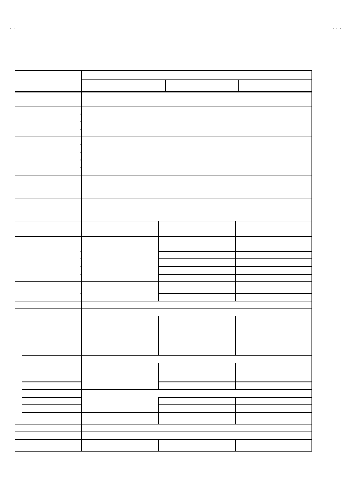
SPECIFICATIONS
ITEMS
Dimensions (W××××H××××D) 33 -7 /8” ×30-1/8 ”×23-3 /4” 860 mm ×76 5mm×60 3mm
Mass 14 9.2Ibs / 67.8 kg
Sy stems
TV RF System CCIR(M)
Color System NTSC-M
Sound System BTS C (Multi Channel S ound )
RF C h anne ls a n d F r e qu e nc y
VL B and (02~06 ) 5 4M Hz~88MHz
VH Ba nd (07~13 ) 174M H z~21 6MHz
UH F Ba nd (14~69 ) 470M H z~80 6MHz
CATV rec eivable band Low, High, Mi d, S uper, H y per , U lt ra and Sub M i d ban d available . T otall y 18 0 ch annels.
Video IF Carrier 45 .75 MH z
Sound IF Carrier 41 .25 MH z (4.5M Hz)
Color Sub Carrier 3.5 8 M Hz
Picture Tube 36 ” (90 cm) measur ed diagonally
Aspect ratio 4:3
Hi gh V ol ta ge 31±1.3 kV ( at z er o beam current)
Power Input 120V A C, 60Hz 12 0V A C, 60Hz 12 0V AC, 60Hz
Power Consumption 13 3W 13 0W 13 0W
Comb f ilt er 3 line digital comb filter 3 line digital comb filter 3 line digital comb filter
Pict ure- In - Pictu re 2 t uner PI P NO NO
Hyper surround YES YES NO
Language options En gl ish , Fren ch an d Sp anish En gl ish , Fren ch an d Spani sh English , F ren c h an d Sp anish
V-CHIP US / CA US / CA US / CA
On / Off, Sleep timer YES YES YES
Speaker
Audio Power Output 3W+3W 3 W+3W 3W +3W
Input / Output terminals
INPUT1
Vide o 1Vp-p, 75 Ω 1V p-p, 75 Ω 1V p- p, 75 Ω( superi mp oses Y)
S-Video
Component (Y, Pb, Pr
Audio L/R 0.5 Vrms, hi gh imp edan c e 0.5 Vr ms, hi gh i mp edan c e 0.5 Vr ms, hi gh i mp edan c e
INPUT2
Vide o 1Vp-p, 75
Component (Y, Pb, Pr
Audio L/R 0.5 Vrms, hi gh imp edan c e 0.5 Vr ms, hi gh i mp edan c e 0.5 Vr ms, hi gh i mp edan c e
INPUT3
Vide o
Audio L/R 0.5 Vrms, hi gh imp edan c e 0.5 Vr ms, hi gh i mp edan c e - -- - -----
Audio Output (Fix)
AV Compu linkⅢⅢⅢⅢ in t erface 3.5 mm mini jac k
Antenna terminal 75 Ω (V HF/UHF) Termin al , F -Type C on nector
Remote Control Uni t
Design & specifications are subject to change without notice.
3-1/4 ”×4- 3/4 ” ( 8×12cm)
Y : 1V p- p, ne gative sync
C : 0.2 86V p- p, 75Ω
YorV : 1V p- p, ne gati ve syn c
Pb/Pr : 0.7 Vp-p, 75Ω
1V p- p, 75 Ω 1V p-p, 75 Ω
0.5 Vr ms, low Imp edanc e,
1kH z when modulated 100 %
RM-C 254
(AA/R6/UM-3 battery×2)
AV-3636 0
AV -3 6S3 6
×
2
--------- ---------
Ω
/M /R
/M /R
3-1/4 ”×4- 3/4 ” (8×12cm)
Y : 1V p- p, ne gative syn c
C : 0.2 86V p-p, 7 5Ω
1V p- p, 75
YorV : 1V p- p, ne gati ve syn c
Pb/Pr : 0.7 Vp-p, 75Ω
0.5 V rms, low Imp edanc e,
1k Hz wh en m odul ated 100 %
RM-C 255
(AA/R6/UM-3 battery×2)
CONTENTS
AV-3633 0
AV -3 6S3 3
×
2
Ω
/M /R
/M /R
AV-3632 0
3-1/4” ×4- 3/4 ” (8×12cm)
×
2
Y : 1V p- p, ne gative sync
C : 0.2 86V p- p, 75Ω
YorV : 1V p- p, ne gati ve syn c
Pb/Pr : 0.7 Vp-p, 75 Ω
1V p- p, 75
0.5 Vr ms, low Imp edanc e,
1kH z when modulated 100 %
RM-C 205
(AA/R6/UM-3 battery×2)
Ω
/M /R
---------
---------
2
No.51950
Page 3
A
6
A
3
A
SAFETY PRECAUTIONS
V-36360 AV-36S3
V-36330 AV-36S3
V-36320
1. The d esi gn of t his p ro du ct c ont ains s pec ial h ar dw ar e, man y
ci rcu its and c o mp on ent s s peci al l y for saf ety pur p oses. F or
continued protection, no changes should be made to the
origina l des ign u nless a uth or i zed in wri ting by t he man ufactu re r.
Replacem en t par ts m ust be id ent ic al t o t hos e used in th e
origina l circui t s. S er vic e s ho ul d be perf or me d b y qu ali fied
p ers onnel o nly.
2. Alte r ation s of th e des ig n o r circu itr y of the p rodu cts s hould n ot
b e m ad e. A ny de sign alte ra tions or ad di ti o ns will vo id th e
manufacturer's warranty and will further relieve the
manu fac t urer of resp ons ibi lit y f or pe rs ona l i n ju r y or p r ope rt y
d am age r esult ing t heref rom .
3. M an y e lectrical an d mec h an ic al pa rt s in th e produ cts h ave
sp ecial s af ety-r elat ed charact eris tic s. Th ese charac teri sti cs ar e
oft en not e vid en t fr om visu al in spe ction no r can t he prote cti on
aff orde d by th em n ecess ar ily be o bta ined b y usi ng
replac ement compon ent s rated for h ig her vo l tag e, wa ttage, etc.
Replacem en t pa rt s wh ic h h ave t hes e sp ec ial s afet y
ch aracter istics a re i d entifi e d in th e par ts l ist of S ervic e man ua l.
Electrical components having such features are identified
by shading on the schematics and by (!!!!) on the parts list
in S erv ice manual. Th e us e of a su bst itu te re plac emen t whic h
does not have the same saf ety characteristics as the
reco mmen ded replac emen t pa rt sho wn i n the pa rts lis t of
Se rvi c e ma nu al m ay c ause sh ock, f ire, or o th er haz ards.
4. Use iso la tio n tr ansforme r when hot ch ass is .
The chassis and any sub-chassis con tained in s ome products
are c onnect ed to on e side of th e AC p ow er l i ne . An i sola ti on
tr ansf or m er of ad equ ate cap acity sh ould be inser t ed bet ween
th e p rodu ct and t he AC p ow er s u pp ly p oi nt while p er for m i ng
an y ser vice on so me pr oducts when th e H OT ch assis is
exp ose d.
5. Do n't shor t between the LIVE side ground and I SOLATED
(NE UTRAL) side ground or EARTH side ground when
repairing.
So m e mod el 's p ow er c irc ui t is par t ly dif feren t in the GND. Th e
diff er enc e of t he GN D is s h ow n by th e LI VE : (") side GND,
th e ISO LAT ED(NEU TRAL) : (#) side GND an d EAR T H : ( $)
si de GND. Don 't sho rt be tw ee n t he LIVE s id e GN D a nd
ISO LATE D(N EU TR AL) si de GN D or EART H si de GN D and
never measure with a measuring apparatus (oscilloscope etc.)
th e LI VE s ide GND a nd ISO LATED( N EUTRA L) si d e G ND or
EARTH sid e GND at the s ame time.
If above note will not be kept, a fuse or any parts will be broken.
6. If any repa ir h as b ee n m ad e to th e ch assi s, i t i s re commend ed
th at t he B1 se tti n g s h ou ld b e chec ked or ad jus te d (S ee
ADJUSTM ENT OF B 1 POW E R SUPPLY).
7. The hig h volt ag e app li ed t o the pi ctu re tube must co nfo rm with
that specified in Service manual. Excessive high voltage can
cau se an incr ease i n X- R ay e mi ssi on , arc in g an d possib l e
com po nent d am ag e, th eref or e op er atio n un der ex cess ive hi gh
vol ta ge c ond it i ons sh ou ld be ke pt to a min i mu m, or sh ou ld be
preve nt ed. I f seve re arc ing occu rs, r em ove th e AC p ower
immediately and determine the cause by visual inspection
(incor r ec t i nsta lla ti on , crac ked o r m el te d high vol tag e har ness,
p oor s olde rin g, etc. ). T o ma in ta in the pr op er mi ni m um l e v el of
sof t X- R ay e miss ion , c om p one nts in th e hi g h vol tag e ci r cuitr y
incl ud i ng the pi ctu r e tu be mu s t be the ex a c t r ep lac em en ts or
alte rn at ives a ppr o ved b y th e ma nuf actu r er of th e c o mp l ete
prod uct.
8. Do n ot c hec k high vol ta ge by d r awing a n ar c. U s e a hi gh
vol ta ge m ete r or a hi gh volt age p ro be wi th a VT VM . Disch arge
th e p ictu r e tu be bef ore a tte mp ti ng meter co nne cti on , b y
con nec ting a cl i p lead to th e gr ou nd frame a nd con n ec ti ng t he
oth er e nd of t he lead th roug h a 10 kΩ 2W resist or to t he ano de
bu tto n.
9. W hen s e rvice is r equ i r ed, ob s er ve th e orig inal l ea d dress .
Extra p r ecau ti on s h ou ld be giv en to assu r e cor re ct lea d dr es s
in the hi gh volta ge c ir cu it ar ea . W her e a sh ort ci r cuit ha s
occu rr e d, th ose c ompon en ts th at i nd ic ate ev i den c e of
overheating should be replaced. Always use the
manu fac t urer 's r epl ace m ent com p onents.
10 . Isolation Check
(Safety for Electrical Shock Hazard)
Af ter r e- a s sembling th e pr od uct , always pe rf or m an is o l ation
ch eck on th e expo sed m eta l p ar ts of th e c abi n et ( ant en na
ter m i na ls, vide o/a udio input and out put t er mi n al s, C on trol
knobs, metal cabinet, screwheads, earphone jack, control
sh afts, etc.) to be s ur e th e pr o duc t is saf e t o op er at e wi th out
d ang er of elect ri ca l shoc k.
(1) Di electric Strength Test
The is olat ion b etwe en the AC primary c ircu it and al l m eta l parts
exp osed t o the us er, par t icu l ar l y an y ex po sed metal p ar t h aving
a re tur n pat h to the ch as sis sh ou ld w i ths t and a volta ge of
11 00V AC ( r .m .s.) f or a p eri od of on e sec ond.
(. . . . Withstand a volta ge of 1100 V A C (r.m.s.) to an applian ce
rate d up to 1 20V , and 3 000V AC ( r .m. s.) t o an appl i anc e ra ted
200V or more, for a period of one second.)
Thi s m eth od of test r e qu ires a t es t eq uip ment n ot g en er ally
fou nd in t he servi c e t ra de.
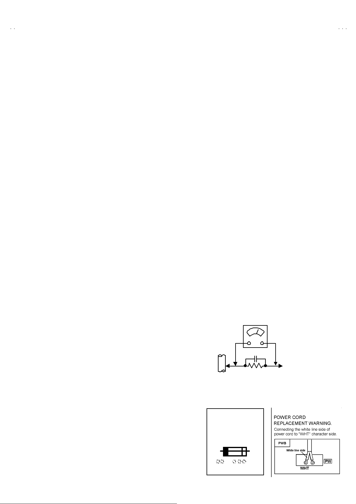
(2) Leakage Current Check
Plug t he A C line cord direct ly i nt o th e AC ou tlet ( do not u s e a
line is olation transf ormer during t his che ck.) . Using a " L eakage
Current Test er", m ea s ur e t he leakag e cur r en t fr om each
exp ose d m eta l par t of th e c a bi ne t, p ar tic ul ar l y an y expo sed
metal part having a retu rn path to t he ch assis, to a kn own good
ea rt h gr o und ( water p ipe, etc.) . A ny l ea k ag e c ur r en t must not
exce ed 0.5m A AC ( r .m. s.) .
Howev e r, in t ro pical a rea, this m ust no t e xc eed 0 .2m A AC
(r.m.s.).
"""" Alte rn at e Che ck M et hod
Plug t he A C line cord direct ly i nt o th e AC ou tlet ( do not u s e a
line isolation transformer during this check.). Use an AC
vol tm et er h av i ng 100 0 ohm s per vol t or m ore s en s iti vity in the
follo win g ma nne r. Connec t a 1 50 0Ω 1 0W resi s tor pa ralle l ed
by a 0.15μ F AC-typ e cap acitor b etwe en an exp ose d m eta l
p art and a k no wn go od earth gr ou nd (wate r pi p e, et c .).
Measu re th e A C vo ltag e acr os s th e r esist or wit h t he AC
voltmeter. Move the res istor connection to each exposed metal
part, particularly any exposed metal part having a return path to
th e ch assis , an d m ea sur e t he A C volta ge acr oss th e r esisto r.
Now, reve rs e the plu g i n t he A C out let a nd r ep e at e ach
measu rem ent. An y volta ge measu red m us t not exce ed 0.7 5V
AC (r.m. s.) . This corresponds t o 0 .5 mA AC ( r.m.s.).
Howev e r, in tr op ic al ar ea, this m ust n ot excee d 0.3V AC
(r.m.s.). This corr esp on ds t o 0 .2mA A C (r.m.s.).
AC VOLT METER
(HAVING 1000 Ω/V,
GOOD
EARTH
GR OUND
11 . High voltage hold down circuit check.
Af ter rep ai r of th e high vol t age h ol d d own c i r cuit, th is ci rcu it
sh all be c hec ked to op er ate cor rectly.
See item "Ho w to check the high voltage hold down
cir cuit".
This mark shows a fast
operating fuse, the
letters indicated below
show the r ati ng.
0.15μF AC-T YPE
1500Ω 10W
OR MOR E SENSIT IVITY)
PLACE THIS PROBE
ON E A C H EX PO SE D
ME T AL PA RT
A V
No. 51950
3
Page 4
A
V-36360 AV-36S36
A
A
5
6
3
V-36330 AV-36S33
V-36320
FEATURES
"
Ti tle T EL E-T EXT br oa dcast of C 1, C2, T1 , a nd T 2 f ormu l a i s rece ivable.
" The voice multiplex f unction of the MTS system is b uilt in.
"
By t he EZ S URF f unc tion, c hann el ID a nd a pr og ra m na me ar e displ aye d i n the s creen au to ma tic all y [ Only f or AV- 3636 0 an d AV-3 6S36].
" By the COMPU LINK Ⅲ function, operation interlocked with the DVD deck can be performed from remote control.
" By the three-line digital comb filter, the refreshed image can be seen.
"
Tw o p ro gram s c a n be d is playe d on th e s cr een b y th e 2 tuner PIP ci r c uit [O nly f or AV-36 36 0 and AV-3 6S36] .
" Exp ressi on of a f avorite scre en c an be ch osen by the VIDE O STA TUS fu nction .
"
A program c an be enjoyed with a powerful sound by the HYPER SURROUND function [Except AV-36320].
" Sinc e the V chip is built i n, i t c an c ho ose, view a nd l ist en t o a h ealt hy pro gram .
"
The RETURN P LUS f unct i on is buil t in .
" A q ui ck f avor ite prog r am c an be look ed for b y th e H YP ER- SC AN fun cti o n.
"
Since the co mp on ent si gn al inp ut t ermi n al i s e qui p pe d, it r ea pp ears dir ect with out deter ior a ting the si gn al fr om D VD,.
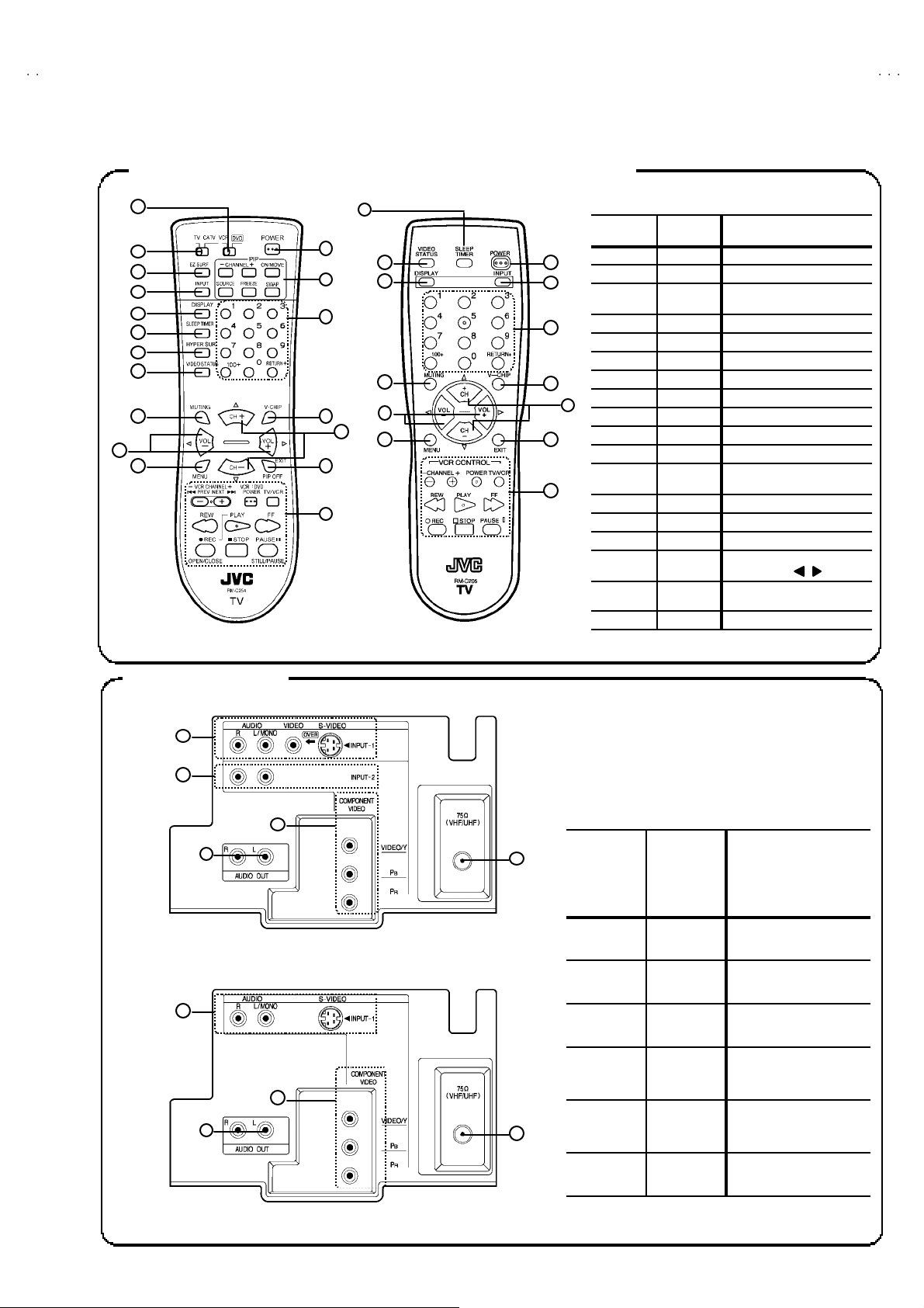
FUNCTIONS
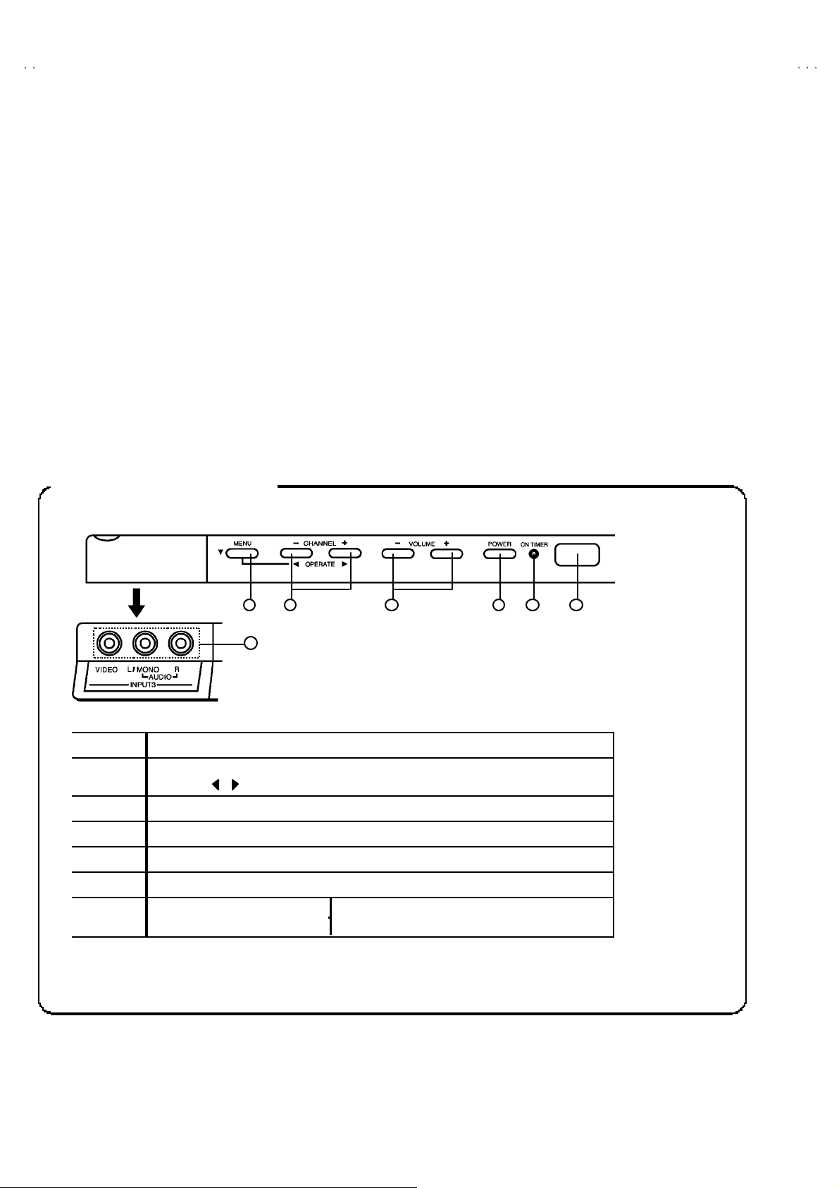
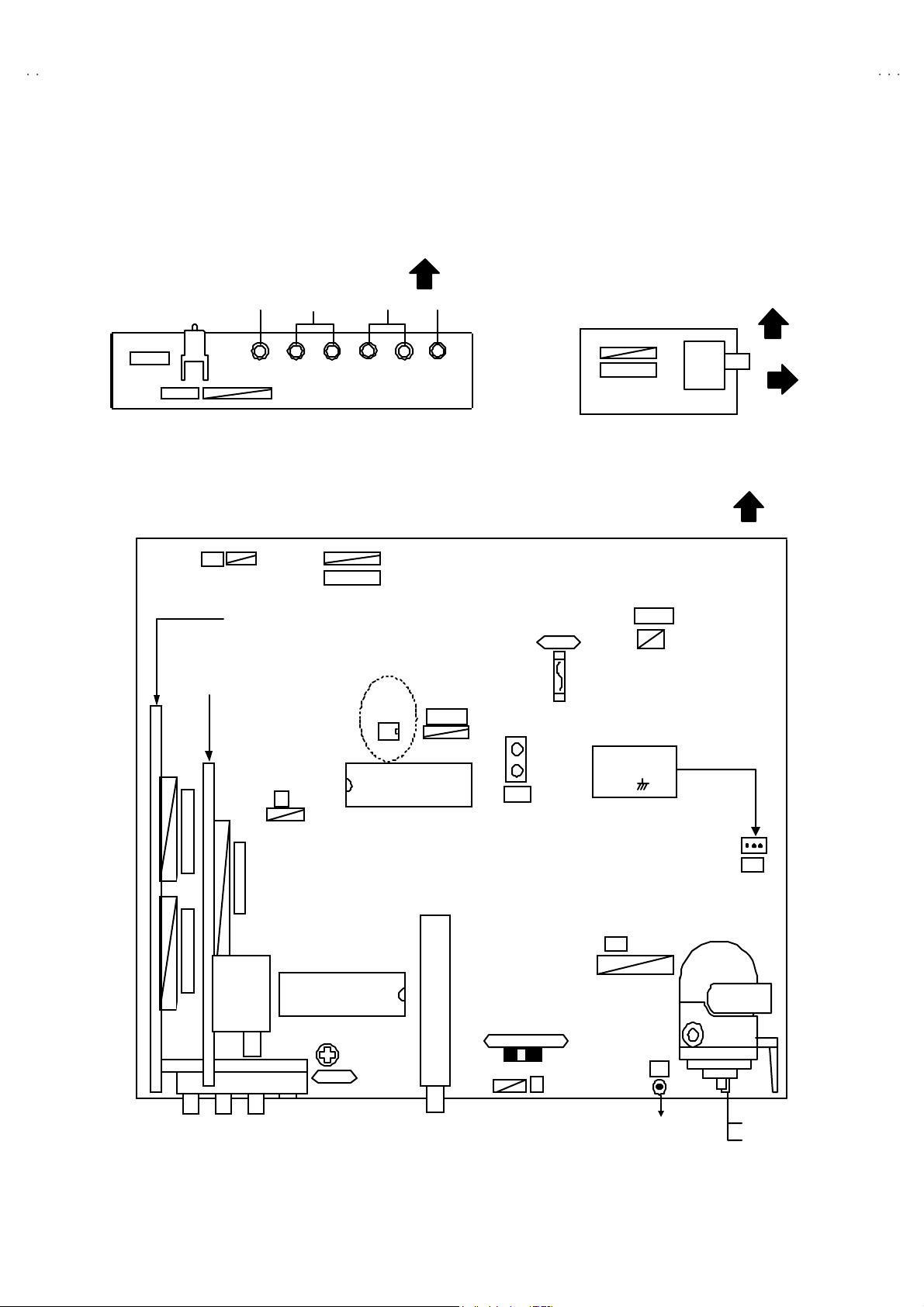
FRONT PANEL CONTROLS
1 4
7
①
②
③ VOL UME -/+ KEY
④ POWE R KEY
⑤ ON TIMER / POW ER LE D
⑥ R EMO CO N W I N DO W
⑦
MENU KEY, SELECT ▼ KE Y
CHANNEL -/+ K EYS
OPE RATE / K EYS
AV -3 6360, 36 33 0, 36S36, 36S33 INPUT 3 TERMINAL (V / L / R)
AV -3 63 20 INPU T 2 TERMI NA L ( V / L / R )
2
4
No. 51950
Page 5
A
6
A
3
A
REMOTE CONTROL UNIT (RM-C254, RM-C255, RM-C205)
5
67893
3
816
3
3134635
6
[
]
[
]
CURSO
V-36360 AV-36S3
V-36330 AV-36S3
V-36320
1
2
4
[RM-C254, 255] [RM-C205]
1
2
12
1
4
14
1
1
RM-C254
RM-C255
7
12
RM-C205 FUNCTION
① ------ VCR / DVD
②
③ ------
④⑦
⑤③
⑥①
⑦ ------ HYPER SURROUND
⑧②VIDEO STATU S
⑨④MUT ING
⑩⑤ME NU
⑪⑥POWE R
⑫ ------
⑬⑧CHANNEL NUMBER
⑭⑨V-CHI P
⑮⑩EX IT
⑯⑪
⑰⑫
⑱⑬VCR CONTROL
------ TV / CATV
EZ SU RF
Only for RM-C254
INPUT
DISPLA Y
SLEEP TIMER
PIP CONTROL
Only for RM-C254
VOL U ME -/ + an d
CURSOR /
CHANNEL +/- an d
R
▲/▼
REAR TERMINAL
[AV-36360, 36S36, 36330, 36S33]
AV-36 360
AV - 36 S33
AV-36 330
AV - 36 S33
①①
②
③③
④
------
⑥⑥
AV-36 320 FUNCTION
------
------
⑤
INPUT 1
S-VIDEO , V, L, R
INPUT 2
L, R
AUDIO O UT (FIX ED)
L, R
INPUT 2
COMPONENT
VIDEO or Y, PB, P
INPUT 1
COMPONENT
VIDEO or Y, PB, P
ANT ENNA S OCKET
F-Type
R
R
[AV-36320]
No. 51950
5
Page 6
A
V-36360 AV-36S36
A
A
)
V-36330 AV-36S33
V-36320
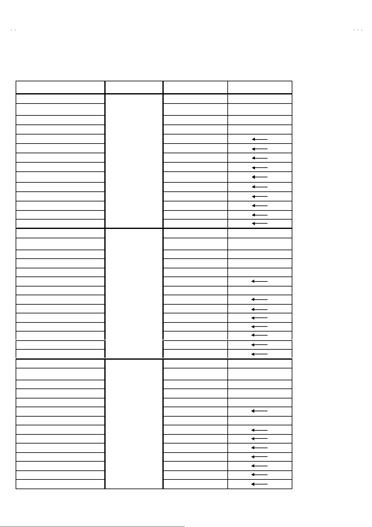
MAIN DIFFERENCE LIST
PARTS NAME MODEL /M /R
ITC TUBE
DEG COIL
MAIN PWB
CRT SOCKET PWB
PIP PWB
AV SELECTOR PWB
E-COAXIAL ASSY
TER MIN AL BO ARD
TAP SCREW (for T ER M . B OARD) QYS BSB30 10 Z (×4)
PUSH KNOB CM35776-B01-H
BRAN D M ARK CM46084-A01
FRONT CA BI . ASSY CM12747-A0G-MA
DOO R
REM OC O N UN IT
ITC TUBE
DEG COIL
MAIN PWB
CRT SOCKET PWB
PIP PWB
AV SELECTOR PWB
E-COAXIAL ASSY
TER MIN AL BO ARD
TAP SCREW
PUSH KNOB
BRAN D M ARK
FRONT CA BI . ASSY
DOO R
REM OC O N UN IT
ITC TUBE
DEG COIL
MAIN PWB
CRT SOCKET PWB
PIP PWB
AV SELECTOR PWB
E-COAXIAL ASSY
TER MIN AL BO ARD
TAP SCREW (for TERM. BOARD)
PUSH KNOB
BRAN D M ARK
FRONT CA BI . ASSY
DOO R
REM OC O N UN IT
(Inc. DY, P C MAGNET, WEDGE)
(Inc. DY, P C MAGNET, WEDGE)
(for TERM. B OARD
(Inc. DY, P C MAGNET, WEDGE)
AV-3 6360
[BLAC K]
AV-3 6330
[BLAC K]
AV-3 6320
[BLAC K]
A90LLD36 1X15 A90AE J15 X01
QQW 0106 -001
or QQW 0114 -001
SGE-1008A-M2 SGE-1032A-M2
SGE-3003A-M2 SGE-3011A-M2
SGE-4001A-M2
SGE-5002A-M2
WJX0014-002A
LC2089 9-00 6A-A
CM36162-005-A
RM-C 254- 1H
A90LLD36 1X15 A90AE J15 X01
QQW 0106 -001
or QQW 0114 -001
SGE-1011A-M2 SGE-1041A-M2
SGE-3003A-M2 SGE-3011A-M2
××
SGE-5002A-M2
××
LC2089 9-00 6A-A
QYS BSB 30 10Z (×4)
CM35776-B01-H
CM46084-A01
CM12747-A0G-MA
CM36162-005-A
RM-C 255- 1H
A90LLD36 1X15 A90AE J15 X01
QQW 0106 -001
or QQW 0114 -001
SGE-1014A-M2 SGE-1047A-M2
SGE-3003A-M2 SGE-3011A-M2
××
SGE-5003A-M2
××
LC2089 9-00 7A-A
QYS BSB 30 10Z (×3)
CM35776-B01-H
CM46084-A01
CM12747-A0G-MA
CM36162-005-A
RM-C 205- 1C
CELD067-001JA
or QQW 0136 -001
CELD067-001JA
or QQW 0136 -001
CELD067-001JA
or QQW 0136 -001
6
No. 51950
Page 7
A
6
A
3
A
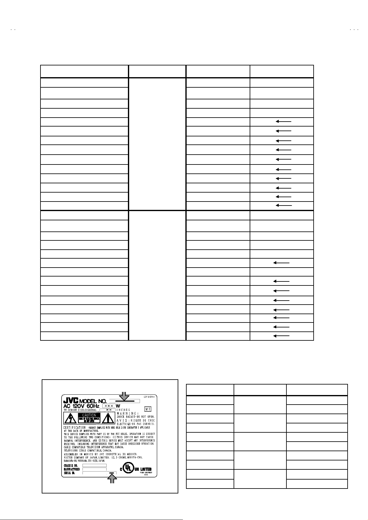
PARTS NAME MODEL /M /R
)
ITC TUBE
DEG COIL
MAIN PWB SGE-1008A-M2 SGE-1032A-M2
CRT SOCKET PWB SGE-3003A-M2 SGE-3011A-M2
PIP PWB SGE-4001A-M2
AV SELECTOR PWB SGE-5002A-M2
E-COAXIAL ASSY WJX0014-002A
TER MIN AL BO ARD LC2089 9-00 6A-A
TAP SCREW
PUSH KNOB CM35776-005-H
BRAN D M ARK CM46084-002
FRONT CA BI . ASSY CM12747-00S-MA
DOO R CM36162-014-A
REM OC O N UN IT
ITC TUBE
DEG COIL
MAIN PWB
CRT SOCKET PWB
PIP PWB
AV SELECTOR PWB
E-COAXIAL ASSY
TER MIN AL BO ARD LC2089 9-00 6A-A
TAP SCREW (for T ER M . B OARD) QYS BSB30 10 Z (×4)
PUSH KNOB
BRAN D M ARK
FRONT CA BI . ASSY
DOO R
REM OC O N UN IT
(Inc. DY, P C MAGNET, WEDGE)
(for TERM. B OARD
(Inc. DY, P C MAGNET, WEDGE)
AV -3 6 S 3 6
[SILVER]
AV -3 6 S 3 3
[SILVER]
A90LLD36 1X15 A90AE J15 X01
QQW 0106 -001
or QQW 0114 -001
QYS BSB 30 10Z (×4)
RM-C 254- 1H
A90LLD36 1X15 A90AE J15 X01
QQW 0106 -001
or QQW 0114 -001
SGE-1011A-M2 SGE-1041A-M2
SGE-3003A-M2 SGE-3011A-M2
××
SGE-5002A-M2
××
CM35776-005-H
CM46084-002
CM12747-00S-MA
CM36162-014-A
RM-C 255- 1H
CELD067-001JA
or QQW 0136 -001
CELD067-001JA
or QQW 0136 -001
V-36360 AV-36S3
V-36330 AV-36S3
V-36320
HOW TO IDENTIFY MODELS
How to r ec ogn i ze fr om th e ap p ear an ce of th e mo de l co ncern ed i s wr itt en b el o w. Ple ase dist ingu is h f r om se veral c ont ents cu rren tl y printed on
th e r at ing l a bel.
Model Name
AV-36 360 /M M
AV-36 360 /R
AV-36 330 /M M
AV-36 330 /R
AV-36 230 /M M
AV-36 230 /R
AV-36S36 /M M
AV-36S36 /R
AV-36S33 /M M
Detailed Model Name
AV-36S33 /R
No. 51950
Model Name Detailed Model Number
AV-36 360
AV-36 330
AV-36 320
AV - 36 S36
AV - 36 S33
R
R
R
R
R
7
Page 8
A
V-36360 AV-36S36
A
A
C
V-36330 AV-36S33
V-36320
SPECIFIC SERVICE INSTRUCTIONS
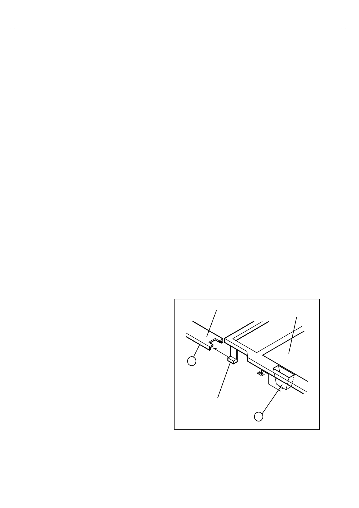
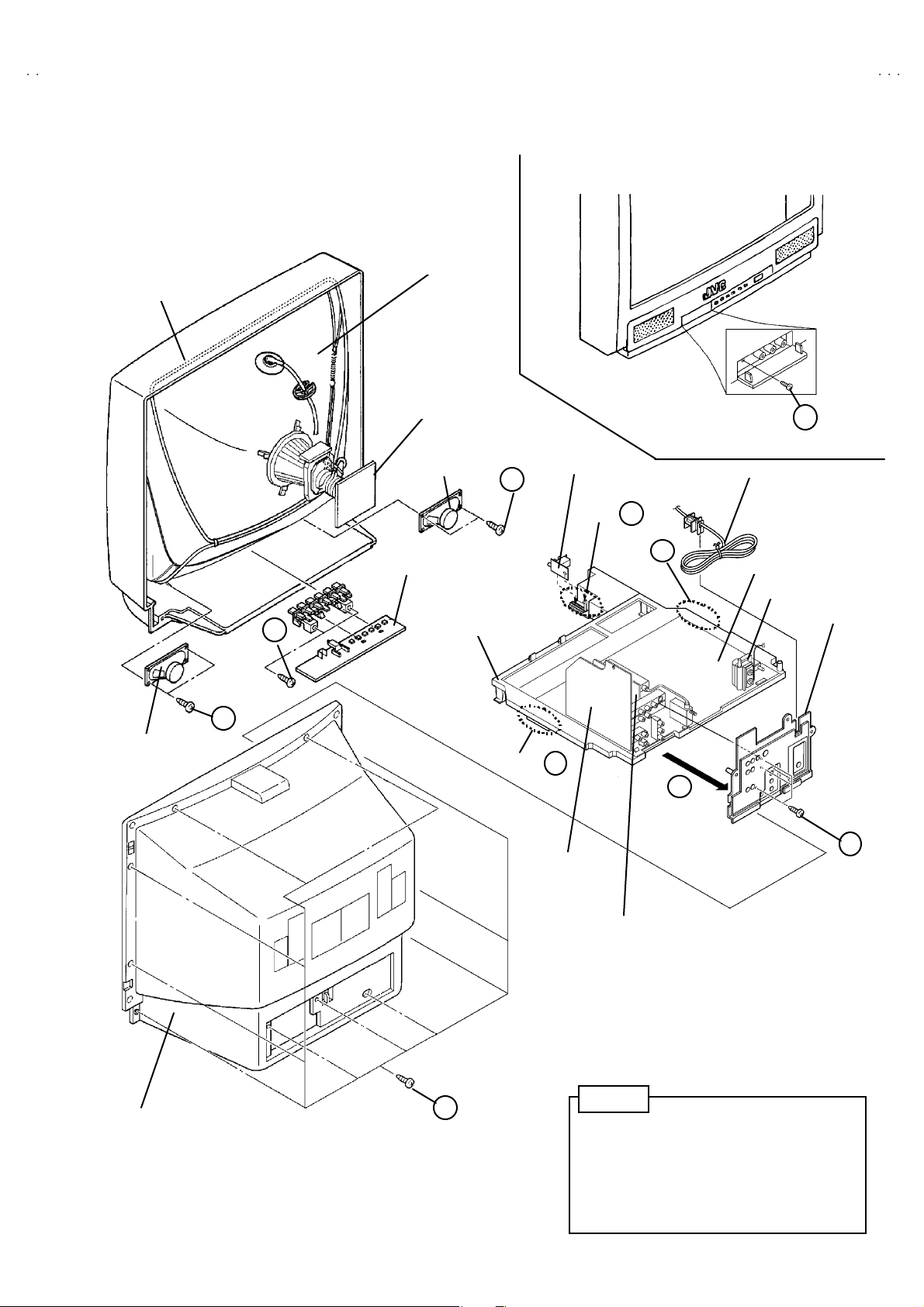
DISASSEMBLY PROCEDURE
REMOVING THE REAR COVER
"
Unplug t he power plu g.
1. As s hown in Fig.2 , r emove the 11 screws marked
2. Remove the rear cover toward you.
Note :
When re i nsta lling th e rear cov er , c are fu lly pus h it inw ar d af ter
inserting the chassis into the rear c over groove.
!!!!
.
REMOVING THE CHASSIS BASE
"
After removing the rear cover.
1. Sl i ght ly raise th e bot h s ides of th e ch assi s b ase b y hand , and
remove the 2 cl aw s m ar ked "
sides of the chassis from the chassis rail.
2. As sho wn i n F ig .1, dr a w t he ch assis b ase b ackwar d alon g t he
chassis rail m arked #
(If necessary, detac h the wire clamp, connec tor’s etc.)
Note :
When con du cting a c hec k with po we r sup pl i ed , b e su re to conf irm
th at th e CRT ea rt h wire i s c onn ect ed to the CRT SOCKET PW B
an d t he MA IN PW B .
#in the arrow dire ction marked $$$$(Fig.2.).
##
" ( Fig. 1 a nd F i g.2 ) unde r th e both
""
REMOVING THE TE RMINAL BOARD
" After removing the rear cover.
1. As s hown in Fig.2 , r emove the 4 screws marked%&
(In case of disassembly the AV-36320, remove the 3 scre ws
marked &
&.)
&&
2. When you pu ll ou t th e TE RMIN AL BOARD, it ca n b e re mo ved .
%&
%&%&
.
REMOVING THE SPEAKER
" After removing the re ar cover and chassis base.
1. As s hown in Fi g.2 , r em ove t he 2 screws marke d *
2. F ol low th e s ame st eps wh en rem ovin g the oth er h and spe ake r.
*.
**
CHECKIN G THE MAIN PW BOARD
1. To c h ec k the bac ks id e of t he MA IN PW Boar d.
(1) Pu ll ou t th e c has sis b as e . (Refe r to RE MO VING T HE
CHA SSIS BASE) .
(2) Erect the chassis vertic ally so t hat you can easily chec k fro m
the backside of the MAIN PWB.
CAUTION
" W hen er ec ti ng th e chass is, be c arefu l so t hat the r e will be n o
con tact ing with ot her PWB .
" Be for e tu rn i ng on po wer , make s ur e th at th e C RT e ar th w ir e and
oth er co nn ec to rs are p ro per l y co nn ecte d.
WIRE CLAMPIN G AND CABLE T Y ING
1. Be sure to cla mp th e wire.
2. Never r em o ve th e c able tie use d f or tying th e wires to ge the r.
Sh oul d it be i n adv e rt ent l y rem ove d, be su r e to tie the wires with
a n ew c able tie.
FRONT CABINET
MAIN PWB
REMOVING THE FRONT CONTROL PW BOARD
" After removing the re ar cover and chassis base .
1. As s hown i n Fig.2, r emove the 2 screws marked '
FRONT CONTROL PWB with th e front cabin et.
2. The n remo ve th e FRONT CONTROL PW B.
REMOVING THE FRONT AV IN PW BOARD
"
After removing the rear cover and chassis base.
1. Rem ove the sc r ew m ar ked (
2. As shown in Fig.2, pull the claw marked )
3. The n rem o ve th e FRONT AV IN PW B.
8
( at the fr on t inp ut termi nal.
((
).
))
'att ach ed the
''
No. 51950
CHASSIS BASE
B
Fig. 1
Page 9
A
6
A
3
A
FRONT CABINET
V-36360 AV-36S3
V-36330 AV-36S3
V-36320
CRT
SP EAKER
CRT SOCKET PWB
FRONT AV IN
SP EAKER
J
FRONT CONTROL PWB
F
CHASSIS BASE
PWB
CLAW
H
CLAW
POWER CORD
B
MAIN PWB
G
HV T
TERMINAL BOARD
J
CLAW
B
D
E
AV SE LECTOR
PWB
PIP PW B
[Only for A V -363 60 and A V- 36 S3 6]
REAR COVER
A
Fig.2
No. 51950
No te
Thi s illu str ation des cri b es ab ou t AV -3 63 60.
Alth ou gh th e oth er mod el s are slig htl y di f feren t
from this illustration, it can use for the other models
in t he same s t eps as t hi s illus tr atio n.
9
Page 10
A
V-36360 AV-36S36
A
A
V-36330 AV-36S33
V-36320
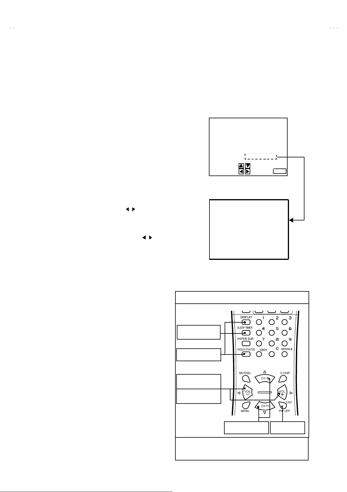
MEMORY IC REPLACEMENT
1. Memory IC
This model uses the memory IC.
Thi s m em or y IC st ores d ata f or pr oper o pera tion of the vide o/ch ro ma a nd d eflecti o n c ircui ts.
When r ep la c ing, be sure to use th e IC c ont ai ni n g i ni ti a l se tting data .
2. Memory IC replacement procedure
(1) Power off
Switch off th e pow er an d di s con nec t th e p ow er plu g f rom t he AC ou tlet.
(2) Replace the memory IC
Be sure to use the memory IC written with the initial setting values.
(3) Power on
Connect th e pow er pl u g t o the AC ou tl et an d switch on th e pow er .
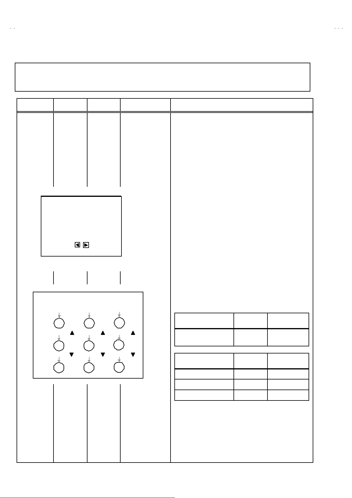
(4) System constant check and setting
①
Press the SL E EP T IM ER ke y and se t SL EEP T IM ER f or 「0 min」.
②
Be for e di s a pp ear t he display of SL EEP T IM ER s ett ings, si mu l tan eo usly
press th e DISPLAY ke y and VI DE O ST ATUS key of t he remot e control unit.
The SERVICE MENU screen of Fig.1 will be displayed.
③
While the SERVICE MENU is displayed, select the SYSTEM(SYS) item
wi t h CURSOR ▼/▲ key an d g o in to with / key s. T h en the S YST E M
mode screen will be displayed as shown in Fig.2.
④ Refe r to t he ta ble of SY STEM CONSTAN T given in pa ge la ter , an d ch ec k
th e eac h i tem . If the v alu e i s diff eren t, s el ect t he settin g item with th e
CURSOR ▼/▲ ke y, an d s etti n g w it h the CURS OR / keys. (The let ters
of the selected item is displayed in yellow.)
⑤ When adj ust me nt h as c ompl ete d, the values st ore i nt o memor y IC
automatically.
⑥
Press the EX IT ke y twic e t o retur n to the normal scree n.
SE RVICE MENU
SERVICE MENU
1.V/C(S) 2.DEF(D)
3.SOUND(A) 4. O THERS
5.PIP(PIP) 6.3L Y/C(LYC)
7. LO W LIG HT 8. HIGH LI G HT
9.RF AFC 10.VCO
2
C BUS 12.SYSTEM(SYS)
11.I
SELECT BY
OPERATE B Y EXIT BY
Fig.1
12. SY STE M (SY S) MODE
SYS01 VIDEO
Fig.2
EXIT
***
(5) Receiving channel setting
Refe r to the OP ERATING INS T RUCTIONS an d set th e receive
channels (Channels Preset) as described.
(6) User settin gs
Check t he us er se tting i t ems accor di n g to th e Ta ble 2 given in pag e
later.
Wher e th ese d o not a gr ee , refe r to the OPERAT ING
INSTRUCT IONS an d s et t he i tem s as desc rib ed.
(7) SERVICE MENU setting
Ve rif y wh at to se t i n t he SERV IC E M ENU, and s et w h at ever is
necessary (F ig.1 ) . Refer to th e SE RVIC E A DJUSTM ENT f or set ting.
KEY ASSIGNMENT OF REMOTE CONTROL UNIT
①
Setti ng fo r “0 min”
②
Simulta neously push
③
Go into th e ite m
④
Setti ng th e value
③, ④
Se le ct t he it em
Alth ou gh t hi s illus tr ati on of re mo te c ont ro l unit is written ab ou t
RM-C 25 4 (A V-36 360 ) , it c an use for op erati ng the oth er m od el
of remote control unit as same key assignment.
EXIT from
SY STEM m od e
10
No. 51950
Page 11
A
6
A
3
A
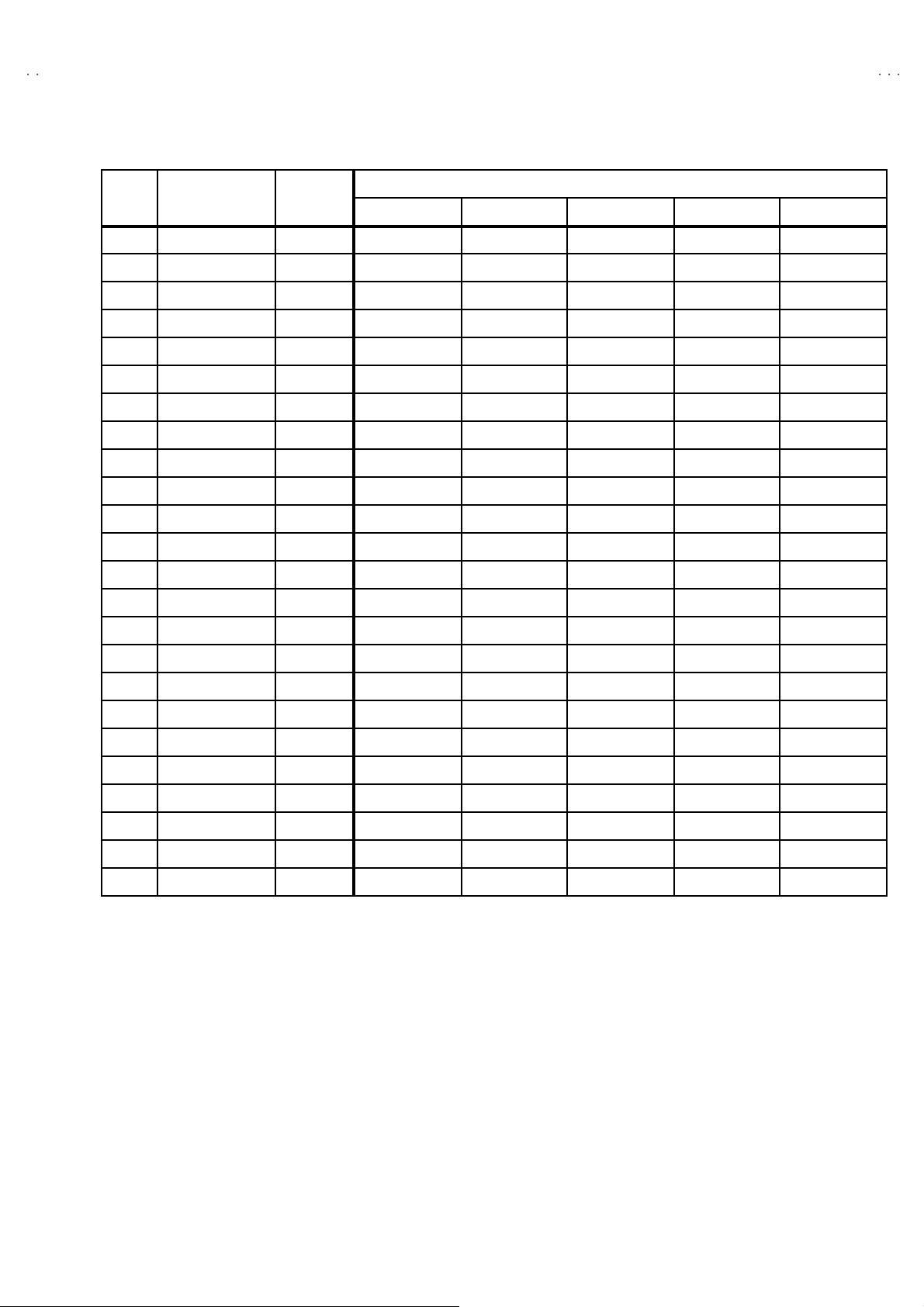
VALUES OF SYSTEM CONSTANT (TABLE 1)
V-36360 AV-36S3
V-36330 AV-36S3
V-36320
ITEM C ONT ENTS
SY S01 VIDEO IN 0~433332
SY S02 PIP 0~111000
SY S03 3D Y/ C 0~100000
SY S04 Y CV 0~100000
SY S05 CCD PCH K 0~111111
SY S06 PUR ITY 0~100000
SY S07 VM 0~100000
SY S08 NOISE C R 0~100000
SY S09 CLR TEMP 0~100000
SY S10 TH EATE R 0~100000
SY S11 TH EATE R PRO 0~100000
SY S12 BB E 0~100000
SY S13 HYP SU RR 0~111110
SY S14 16:9 MD 0~100000
SY S15 HYP S CA N 0~111111
VARIABLE
RANGE
AV-36 360 AV-36 S36 AV-36 330 AV-36 S33 AV-36 320
INITIAL SETTING VALUE
SY S16 EZ SU RF 0~111000
SY S17 ID DISP 0~111110
SY S18 COMPU LIN K 0~100000
SY S19 CCD 0~111111
SY S20 VCH IP 0~111111
SY S21 VCH IP C A 0~111111
SY S22 JVC L OGO 0~111111
SY S23 CMP IN 0~111110
SY S24 CXA1 875 0~100000
No. 51950
11
Page 12

A
V-36360 AV-36S36
A
A
]
]
V-36330 AV-36S33
V-36320
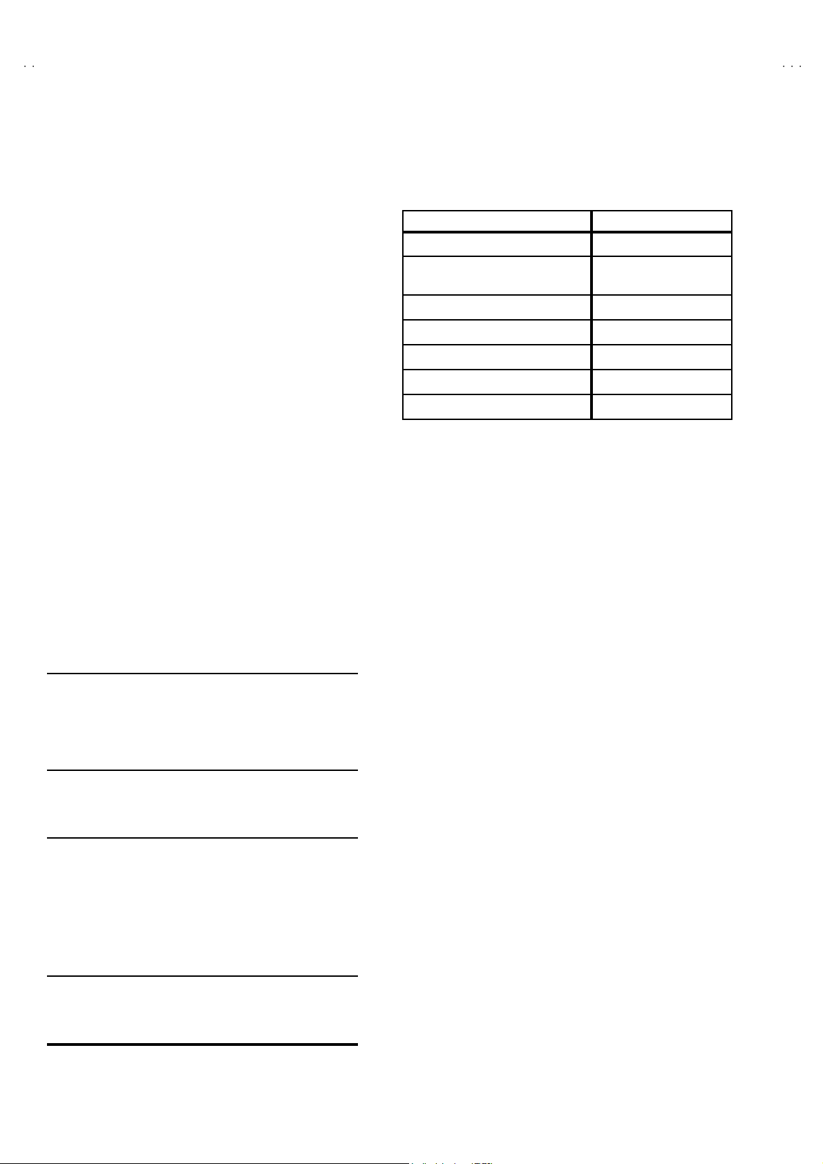
VALUES OF USER SETTING ITEMS (TABLE2)
Setting of switches on fr ont panel and remote control unit
ITEM INITIAL SETTING VALUE ITEM INITIAL SETTING VALUE
POWE R OFF DISPLA Y OFF
CHA NNEL CABL E CH-0 2 VIDEO STATU S DYNAMIC
VOLUME 10 PIP SOURCE CABLE CH-04 [Only AV-36360, 36S36
INPUT TV PIP POSITION L eft lower side [Only AV-36360, 36S36
HYPE R S U RROU ND OFF [Except AV -3 63 20 ] SLEEP TIMER 0
Setting of MENU scr een
PICTURE ADJUST INITIAL SETUP
TINT CENTER LANGUAGE ENG
COLOR CEN TER FR ON T PANEL LOCK OFF
PICTURE +8
BRIGHT CEN TER
DETAIL +10
NOISE M UT ING ON
SOUND ADJUST CLOS ED CAPTIO N OFF
BA SS C EN TER CAPT IO N : C C1
TR EBL E CEN TER TEXT : T1
BALANCE CENTER AUTO TUNER SET UP TUNER MODE : CABLE
MTS STE RE O CHANNEL S U MMAR Y Unn ecess ary to set
CLOCK / TIMERS V-CHI P OFF
MANUA L SET US TV RATINGS ALL CLEAR
TIME ZONE : PACIFIC SET MOVIE RATINGS ALL CLEARSE T CLOC K
D.S.T : OFF SET CANADIAN RATINGS ENG ALL CLEAR
ON/OFF TIMER OFF SET CANADIAN RATINGS FRE ALL CLEAR
V2 COMPONENT -I N
[AV-36360, 36S36, 36330, 36S33]
V1 COMPONENT -I N
[AV-36320]
AUTO S HUT OFF OFF
XDS I D ON [E xc ept AV-3 63 20]
UNRATED VIEW
NO
NO
SET LOCK CODE “0000”
12
No. 51950
Page 13

A
6
A
3
A
REPLACEMENT OF CHIP COMPONENT
!
CAUT IONS
1. Avoid heating for more than 3 seconds.
2. Do n ot ru b the elect ro des an d the r esis t p arts of the p att ern.
3. W hen r em ov i ng a c hip part, mel t th e s older ad equate ly.
4. Do n ot reuse a chip p ar t afte r re mo v ing it .
! SOLDERING IRON
1. Use a hig h i ns ulati o n s ol der ing i r on with a thi n poin ted e nd of it.
2. A 3 0 w s older i ng i r on is rec omm end ed for easily r em oving p arts.
! REPLACEMENT STEPS
1. How to remove Chip parts
#### Resi st o rs, capacit ors , etc
(1) As sh own in the f ig ur e, pu sh th e pa rt w ith tw ee zer s and
alte rn at ely melt the s ol de r at eac h end.
(2) Sh if t with tweeze rs and r em ove th e c h i p p art.
#### Trans ist ors, diodes , va ria bl e r esist or s, etc
(1) Ap pl y e xt ra so ld er to eac h le ad .
SOLDE R SOLD E R
V-36360 AV-36S3
V-36330 AV-36S3
V-36320
2. How to install Chip parts
####
Resi st o rs, ca pacit o rs , etc
(1) Ap ply sold er to the pattern as indic ate d in the figure.
(2) Gr asp the c h i p p art with tw ee zer s and pl ac e it on th e s old er.
The n hea t and me lt th e so lder a t both ends of t he chi p part.
#### Tran s istors, diodes , varia bl e res ist or s, et c
(1) Ap ply sold er to the pattern as indic ate d in the figure.
(2) Grasp the ch ip p art wit h t we ezers and p lace it on th e so lder .
(3) First s older lead A as indica ted in t he figure.
A
(2) As sh own in the f ig ur e, pu sh th e pa rt w ith tw ee zer s and
alte rn at ely melt th e sol d er at each le ad . S hi ft an d r em ove the
chip part.
(4) T he n s o ld er l e ads B and C.
Note : A fte r re moving t he part, r emove rem ain ing solder fr o m the
pattern.
C
A
C
No.51950
B
B
13
Page 14
A
V-36360 AV-36S36
A
A
]
V-36330 AV-36S33
V-36320
SERVICE ADJUSTMENT
BEFORE STARTING SERVICE ADJUSTMENT
1. There are 2 way of adjusting this TV : One is with the r emote
control unit and the other is the conventional method using
adjustment parts and components.
2. The adjustment with the REMOTE CONTROL UNIT is made
on the basis of t he initial setting v alue s. The setting va lues
which adjust the screen to its optimum condition may differ
from the init ia l s etting v al ues.
3. Make s ur e th at conn ec t ion i s c orrec t ly ma de t o AC p ower
source.
4. Turn on the p ower of th e se t an d equipmen t bef or e us e, an d
start t he ad ju stm en t proc edure s af ter waitin g at least 30 mi n utes.
5. Unl ess ot her wise s pec ified, pr ep are th e mo s t s uita bl e r ec eptio n
or inp ut sign al for adjust ment.
6. Nev er t ouc h an y ad j ustm en t p arts , wh ich a r e n ot sp ecif ie d i n the
list for this adjustment VRs, transforms, condensers, etc.
7. Prep ar ati o n for ad j ustm en t
Unless otherwise specified in the adjustment instructions, preset
the following functions with the REMOTE CONTRO L UNIT.
User menu preset value
VIDEO STATU S STA NDARD
TINT, COLOR, PICTURE
BRIGHT, DETAIL
NOISE M UTI NG OFF
PIP [Only for A V-36360, AV-36S36
BA SS, TREB LE, BA LANCE
H YPE R S U RRO U ND
MTS
MENU ITEM PRES ET V ALU E
Set f or initial setting value
OFF
CENTER
OFF [E xc ept AV -3 63 20]
STEREO
MEASURING INSTRUMENT AND FIXTURES
1. DC voltmeter (or digital voltmeter)
2. Oscilloscope
3. Si gn al g en er ator (P attern g en erat or) [ NTS C]
4. Remote control unit
5. TV a ud io m ulti pl e x sign al ge ne rator
6. F requ enc y cou nte r
ADJUSTMENT ITEMS
BASIC ADJUSTMENT
!
Check of B1 pow er s upp l y
! MAIN / S U B VCO ad justment
!
RF AGC ad jus tm ent
! FOCUS adjustment
DEFLECTION CIRCUI T ADJUSTMENT
!
V. CENTER / V SIZE ad ju stment
! H SIZE / H POSITION / SIDE PINCUSHION adjustment
VIDEO / CHROMA CIRCUIT ADJUSTMENT
!
WHITE BALANCE adjust ment ~LOW LIGH T ~
!
WHITE BALANCE adjust ment ~HIGH L IGHT~
! SUB B RI GH T adjustment
!
SUB CONTRAST adjustment
! SUB COLOR adjustment
!
SUB TI NT adjus tment
PIP CIR C UIT ADJ UST MENT [ A V- 36 360, AV-3 6S3 6]
! WHITE BALANCE adjustment ~HIGH LIGHT~
!
DISPL A Y POS ITION a djust me nt
MTS CIRCUIT ADJUSTMENT
! IN PU T LE VEL c h eck
!
SE PARATIO N adjustm ent
14
No. 51950
Page 15
A
6
A
3
A
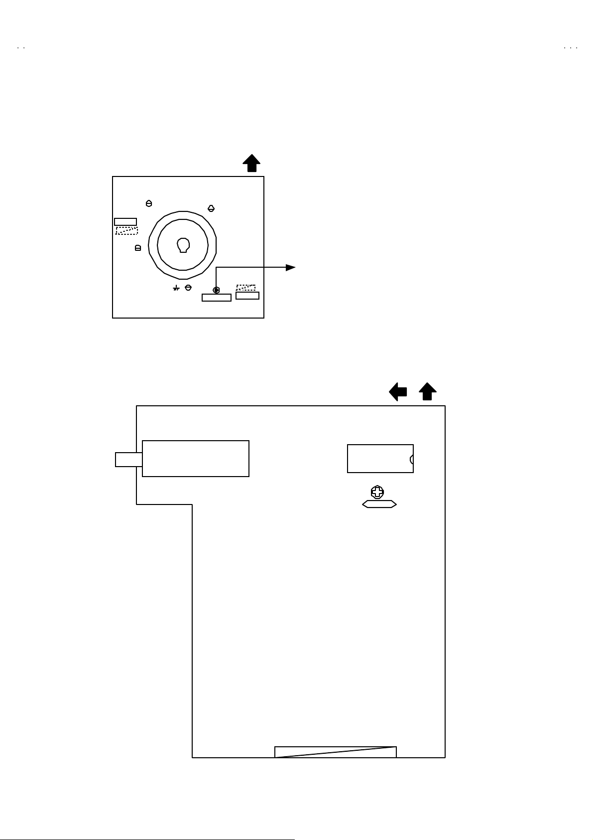
ADJUSTMENT LOCATIONS
[
]
V-36360 AV-36S3
V-36330 AV-36S3
V-36320
FRONT
FRONT CONTROL PWB
POWER MENU
IC7701
CN7007
SS
AV SELECTOR PW B
PIP PWB
Only for AV-36360
and AV-36S36
VOL CH
CN007
MEM ORY I C
IC702
CN004
FRONT AV IN PWB
CN6006
MAIN PWB
F901
FUSE
FUSE
FUSEFUSE
DEG.
J6401
TOP
FRONT
FRONT
CN001
CN003
CN002
TUNER
1:TP-91(B1)
2:NC
T
IC101
T111
VCO
VCO
VCOVCO
IC201
TUNER
PW
V CENTER SW
V CENTER SW
V CENTER SWV CENTER SW
U
S421
3:TP-E( )
HV
CRT EARTH
(BRAIDED ASS'Y)
1
3
B1
HVT
HVT
HVTHVT
E1
UPPER : FOCUS
LOWE R : SCR EEN
No. 51950
15
Page 16
A
V-36360 AV-36S36
A
A
(
)
V-36330 AV-36S33
V-36320
TOP
CRT SOCKET PWB
SOLDER SI DE
CN 300 4
TP-G
TP-R
TP-E( )
TP-B
CR T EART H
(BRAIDED ASS'Y)
CN 30E2
CN 300 5
PIP PWB
[Only for AV-36360 and AV-36S36]
TUNER
TOPFRONT
I C4101
SUB VCO
SUB VCO
SUB VCOSUB VCO
T 4111
16
No. 51950
Page 17

A
V-36360 AV-36S3
6
A
3
A
S
U
3.SO UND(A)
S
V-36330 AV-36S3
BASIC OPERATION OF SERVICE MENU
1. TOOL OF SERVICE MENU OPERATION
Operate the SERVICE MENU with the REMOTE CONTROL UNIT.
2. SE RVICE MENU ITEMS
With th e SERVIC E ME NU, v ar i ous ad ju stm ent s can be m ad e, an d th ey ar e b r oad ly c l assi fi ed in th e foll ow i ng item s of a djust ments.
(1) V/C( S) ・・・・・・・ ・・・・・・・・・・・・・ ・・・・・・・・・・・・ VIDEO / CHROMA related circuit adjustment mode
(2) DEFLECTION(D) ・・・・・・・・・・・・・・・・・・・・ ・・ D EF LEC T IO N re l ate d circui t adju s tme nt mod e
(3) SOUND(A)
(4) OTHERS(F)・・・・・・・ ・・・・・・・・・・・・・ ・・・・・・・ W hole system related items adjustment mode
(5) PIP (PIP) [On ly f o r AV- 3 6360, 36S3 6]
(6) 3L Y/C(LYC) ・・・・・・・・・・・・・・・・・・・・ ・・・・・・ 3 l i n e YC se par a tion r e late d c ircui t adj u s tme nt mod e
(7) LOW LIGHT
(8) HIGH LIGH T ・・・・・・・・・・・・・・・・・・・・ ・・・・・・ White bala nce of “HIGH LIGHT” adjustme nt mo de
(9) RF AFC・・・・・・・・・・・・・・・・・・・・ ・・・・・・・・・・・ RF AFC related circuit adjustment mode
(10) VCO ・・・・・・・・・・・・・・・・・・・・ ・・・・・・・・・・・・ ・ VC O related circui t a djust me nt mode
(11) I2C BUS ・・・・・・・ ・・・・・・・・・・・・・・・・・・・・・・・ I2C bus r elat ed c i r cuit ad ju stm en t mod e [Fixed on]
(12) SY ST EM ( SY S) ・・・・・・・ ・・・・・・・・・・・・・ ・・・・ T hi s mod e i s u sed w he n s etti ng up th e wh ol e s ystem .
・・・・・・・ ・・・・・・・・・・・・・ ・・・・・・・・
・・・・・
・・・・・・・ ・・・・・・・・・・・・・ ・・・・・・・
SOUND related circuit adjustment mode
PIP relat ed circ ui t adju stm ent mod e
White bal a nc e of “LO W LIG HT ” adju stm en t m od e
V-36320
BASIC OPERATION OF SERVICE MENU
(1) Ho w to enter SERVICE MENU
Press the SLE EP TIMER key and set the SLE EP TIME R for
[0 MIN].
The n press th e DI SPLAY key an d th e VI DE O ST AT US key of the
remote control unit simultaneously, and the SERVICE MENU
scr een will be di splaye d as shown b el ow .
(2) Selection of SUB MENU SCREEN
In SERVI CE MENU, p ress the CURSOR ▲▲▲▲/▼▼▼▼ key to select any of
th e SU B ME NU ite ms. (Th e l ett ers of th e s el ect ed it ems ar e
displayed in yellow)
If an i te m l i ke to set up becomes yellow , the CURSOR / key
will be pushed and it will go into the mode.
ERVICE MEN
1. V/C(S ) 2.DEF (D)
5.PIP(PIP) 6.3L Y/C(LYC)
7.LOW LIGHT 8.HIGH LIGHT
9.RF AFC 10. VCO
2
C BUS 12.SYSTEM(SYS)
11. I
SELECT BY
OPERATE BY EXIT BY
4.OTH ER
EXIT
SE RVICE MENU
KEY ASSIGNMENT OF REMOTE CONTROL UNIT
①
Setti ng fo r “0 min ”
②
Simulta neously push
③
Go into th e ite m
④
Setti ng th e value
③, ④
Se le ct t he it em
Alth ou gh t hi s illus tr ati on of re mo te c ont ro l unit is written ab ou t
RM-C 25 4 (A V-36 360 ) , it c an use for op erati ng the oth er m od el
of remote control unit as same key assignment.
EX IT
CURSOR ▲/▼ key
Select 1 .V/C( S)~12.S YSTEM(SYS)
1.V /C( S)
2. DEF (D)
11 .I2C BUS
12.SYSTEM(SYS)
CURSOR / key
Go into eac h S UB M ENU
No. 51950
VI DEO/C HROM A
DEF LECT ION
SO UND
17
Page 18

A
V-36360 AV-36S36
A
A
V-36330 AV-36S33
V-36320
(3) Method of Setting
For example, the operation in the case of s etting up VIDEO/CHROMA is expressed below.
EX IT key
Retu rn to t he S ERVIC E
ITEM CONT ENTS
S01 BRIGHT
S02 PICTURE
S03 COLOR
S04 TIN T
S05 DET AIL
S06 BRIGHT +-
S07 PICT + -
S08 COLOR +-
S09 TIN T +-
S10 DET AIL + -
ME NU MA IN
RF 4 : 3 STD LOW
S01 B RIGHT
S02 PI CTUR E
S03 C OLOR
S04 T I NT
***
***
******
***
***
******
***
***
******
***
***
******
CURSOR ▲/▼ key
Se le ct t he it em s fr o m
CURSOR / key
S01 t o S1 0.
Increment or decrement
th e a djust ment value
(4) Others [Only for AV-36360 and AV-36S36]
If go into the 9.RF AFC and 10.VCO items , there will be display the RF AFC MAIN screen an d VCO MA IN sc r een .
Then press the CURSOR / key, the RF AFC SUB screen and VCO SUB screen is displayed.
10.VCO SUB 10.VCO MAIN
TUN ER SUB
HIGH LE VEL
REFE REN CE LEVEL
LOW LEVEL
SYN C NO
9.RF AFC MAIN MODE
CURSOR / key
TUN ER SUB
HIGH LE VEL
REFE REN CE LEVEL
LOW LEVEL
SYN C NO
9.RF AFC SUB
CURSOR / key
TOO HI GH GOOD TOO LOW
TUN ER MA IN
AFC ON
FINE **
18
No. 51950
TOO HI GH GOOD TOO LOW
TUN ER SUB
AFC ON
FINE
**
Page 19

A
6
A
3
A
SERVICE M ENU (M AIN MENU)
SE RV IC E MEN U
1.V /C (S ) 2 .D EF( D )
3.SOUND(A) 4.OTHERS(F)
5.P IP(PIP) 6.3L Y/C(LYC)
7.LOW LIGH T 8.H IGH LIGHT
9.RF AFC 10.VCO
2
C BUS 12.SYSTEM(SYS)
11.I
SELECT BY
OPE RA TE B Y EX IT BY
EX IT
1 .V/ C( S)
R F 4 : 3 S TD L OW
S01 BRIGHT
***
3.SOUND( A)
A 01 IN LE VEL ***
5.PIP(PIP) [Only for AV- 36360, 36S36]
V-36360 AV-36S3
V-36330 AV-36S3
2.DEF(D)
R F 4 : 3 S TD L OW
D01 V FREQ
4.OTHERS(F)
V-36320
***
8.HIGH LIGHT
***
2
11.I
C BUS
[Do n ot adjust ]
2
I
C BUS O N
12.SYSTEM(SYS)
***
PIP01 BRIGHHT ***
7.LOW LIGHT
BR IGH T
***
***
***
***
9.RF AFC MAIN MODE
TOO HIGH GOOD TOO LOW
TU NE R M AI N
AF C ON
FINE **
10.VCO MAIN
F01 OSD POSI ***
6.3L Y/C(LYC)
[Do n ot adjust ]
LYC01 MODE ***
9.RF AFC SUB [Only for AV-36360, 36S36]
TOO HIGH GOOD TOO LOW
TU NE R SU B
AF C ON
FINE
**
10.VCO SUB [Only for AV-36360, 36S36]
***SY S01 VI DE O
TU NE R M AI N
HI G H LE VE L
RE FE RE N C E LE V EL
LO W L EVE L
SY NC NO
No. 51950
TU NE R S UB
HI G H LE VE L
RE FE RE N C E LE V EL
LO W L EVE L
SY NC NO
19
Page 20
A
V-36360 AV-36S36
A
A
V-36330 AV-36S33
V-36320
INITIAL SETTING VALUE O F SERVICE MENU
1. Adjustment of the SERVICE MENU is made on the basis of the initial setting values ; ho wev er, the new setting values which
set the screen in its optim um condition may differ from the initial setting.
2. Do no t ch ange the in itial setting values not li sted in “ ADJUSTMENT”.
V / C(S) M OD E
RF
No . Setting item Variable range
STANDARD THEATER
AV-36 360
AV - 36 S36
S01 BRIGH T 0~1 27 64 - -- --- ---
S02 PICTURE
0~127
55 --- --- ---
S03 C OLO R 0~1 27 55 --- - -- - --
S04 T IN T
S05 D ETAIL
0~127
0~63
64 --- --- ---
37 --- 35 35
S06 BRIGH T + - -32 ~+32 --- +1 ±0-2
S07 PICT + -
-32~+32
--- -10
S08 COLO R +- - 32~+32 --- -3 -2 -2
S09 T IN T+- -32~+32 --- -3 +2 +2
S10 D ETAIL + -
-32~+32
---
±0
S-VI DEO
COM POSITE VI DEO
STANDARD
AV-36 330 , 36S3 3
AV-36 320
±0 ±0
--- ---
COMPONENT INPUT / STANDARD
No. Setting item Variable range
AV-36 360
AV - 36 S36
AV-36 330
AV - 36 S33
/M
/M
/M
/M
AV-36 360
AV - 36 S36
AV-36 330
AV - 36 S33
/R
/R
/R
/R
AV-36 320
/M
AV-36 320
/R
S03 C OLO R 0~12749564958
S04 T IN T 0~12769726972
S05 D ETAIL 0~6 3 40 40 40 40
S06 BRIGH T + - -32 ~+32-1-1-3-3
S07 PICT + - - 32 ~+32 ±0 ±0 ±0 ±0
RF / S-VIDE O / COMPOSITE VI DEO
STANDARD THEATER STANDARD
COM PONENT IN PUT
THEATERNo . Setting item Variable range
LOW HIGH LOW HI GH LOW HI GH LOW HIGH
S11 R C UT OFF 0~2 55 30 - -- - -- - -- - -- - -- - -- - --
S12 G CU T OFF 0~255 30 - -- - -- - -- - -- - -- - -- - --
S13 B CU T OFF 0~2 55 30 - -- - -- - -- - -- - -- - -- - --
S14 R DRIVE 0~1 27 64 --- - -- - -- - -- - -- - -- - --
S15 B D RIVE 0~1 27 64 - -- - -- - -- - -- - -- - -- - --
S16 R CUT+ - - 128 ~+127 --- ±0 ±0 ±0 -10 --- --- ---
S17 G CUT+- -128~+127 --- ±0 ±0 ±0 ±0 - -- - -- - --
S18 B CUT+- -128~+127 --- ±0 ±0 ±0 -10 --- --- ---
S19 R DRV+- -128 ~+127 --- ±0+7 +7±0 - -- - -- - --
S20 B DRV+- -128~+127 --- ±0-9 -9±0 - -- - -- - --
S21 N TSC MAT 0 ~3 33112211
S22 BL ACK S T 0~3 1 --- 1 --- --- --- --- ---
S23 D CRE ST 0 ~1 1 --- 1 --- --- --- --- ---
S24 D CRSW 0 ~1 1 --- 1 --- --- --- --- ---
20
No.51950
Page 21

A
V-36360 AV-36S3
6
A
3
A
V-36330 AV-36S3
V-36320
No . Se tt ing ite m Va riabl e range RF
S25 AS Y SHRP 0 ~75 4 4
S26 BP F FO 0~10 0 ---
S27 KIL R OFF 0 ~10 0 ---
S28 KIL R SEN 0 ~11 1 ---
No. Setting ite m Variabl e ra nge Initial setting value No. Setting ite m Va riabl e range Initial set ting value
S29 RGB MU TE 0 ~10S39Y MUTE0~10
S30 BLUE B 0~1 0 S40 SVM GAIN 0~30
S31 VIDEO SW 0~3 3 S4 1 SV M PH 0~30
S32 CMP AB CL 0~1 0 S4 2 WPL 0~10
S33 OSD AB L 0~1 0 S43 COL GMM 0~10
S34 OSD CON T 0~63 10 S44 V1 GAIN 0~74
S35 SUB CONT 0~15 8 S45 AGC ADJ 0~127 63
S36 AB L GA IN 0~3 0 S46 VMOFF DE -128~+127
S37 ABL PNT 0~33S47APC CLK0
S38 Y G AM MA 0~31
SOUND MODE
S-VI DEO
COM POSITE VI DEO
COM PONENT IN PUT
±
0
~
11
No. Setting ite m Variabl e ra nge Init ial setting value No . Se tting it e m Variabl e ra nge Initial setting value
A01 IN LEVEL 0~1 5 10 A0 4 SAPC 0 / 1 0
A02 LOW SEP 0~63 32 A05 BBE BA SS -128~+127 +3
A03 HI SE P 0~63 32 A0 6 BB E T R E - 128~+127 -4
3L Y / C MODE (Do not adjust)
No. Setting ite m Variabl e ra nge Init ial setting value No . Se tting item Variabl e ra nge Init ial setting value
LYC01 MODE 0~74LYC07GSEL10~11
LYC02 VENH 0~71LYC08COR0
LYC03 PDSOFF 0~10LYC09TRAP0~11
LYC04 CB 0~1 0 L YC1 0 C HT RA P 0~10
LYC05 VNLR 0~15 2 LYC11 CBPF 0~10
LYC06 GSEL0 0~1 0 LYC12 ENHOFF 0~10
~
30
No.51950
21
Page 22

A
V-36360 AV-36S36
A
A
V-36330 AV-36S33
V-36320
DE F M OD E
/M
/M
/M
/M
/M
S-VI DEO
COM POSITE
AV-36 360
AV - 36 S36
AV-36 330
AV - 36 S33
AV-36 320
RF
No . Setting item Variable range
AV-36 360
AV - 36 S36
AV-36 330
AV - 36 S33
AV-36 320
RF
D01 V FREQ 0~30003
D02 AFC GAI N 0~3000 2
D03 H POSI 0~31 16 16 16 16
D04 H POS I+- -128 ~+127 --- --- --- ---
D05 V PHASE 0~7000 0
D06 V P H+- - 128 ~+127 --- --- --- ---
D07 V SIZE 0~+ 127 82 82 60 60
D08 V S IZE+- - 128 ~+127 --- --- --- ---
D09 V CENTER 0~6 3 32 32 32 32
D10 V CENT+- -128~+127 --- --- --- ---
D11 V S CORR 0~155555
D12 V S CO+- -128~+127 --- --- --- ---
D13 V LIN 0~15 13 13 12 12
D14 V LIN+- -128~+127 --- --- --- ---
D15 H SIZE 0~6 3 27 27 32 32
D16 H SIZE +- -128 ~+127 --- --- --- ---
D17 WVMT TOP 0~30000
D18 WVMT BT M 0~3000 0
D19 EWCR TOP 0~31 13 13 13 13
D20 EWCR T+- -128~+127 --- --- --- ---
D21 EWCR BTM 0~3 1 14 14 14 14
D22 EWCR B+- -128~+127 --- --- --- ---
D23 EW PARA 0~6 3 31 31 34 34
D24 EW PARA+- -128~+127 --- --- --- ---
D25 V EHT 0~7000 0
D26 V E HT+- - 128~+127 --- --- --- ---
D27 H EHT 0~70000
D28 H EH T + - -128~+127 --- --- --- ---
D29 TRAPEZ 0~6 3 35 35 35 35
D30 TRAPEZ+- -128~+127 --- --- --- ---
D31 V AGC 0~10000
D32 BLANK SW 0~10000
D33 VRMP BI 0~10000
/R
/R
/R
/R
/R
S-VI DEO
COM POSITE
22
No.51950
Page 23
A
V-36360 AV-36S3
6
A
3
A
V-36330 AV-36S3
V-36320
OTHERS MODE
No. Variabl e ra nge Init ial setting value No. Variabl e range In itial set ting v al ue
F01 0~15 37 F15 0~63 0
F02 0~15 90 F16 0~63 10
F03 0~15 45 F17 0~63 20
F04 0~15 93 F18 0~255 2
F05 0~63 7 F19 -128~+127 + 8
F06 0~10F20-128~+127 -4
F07 0~63 2 F21 -128~+127 -10
F08 0~20F22-128~+127 -16
F09 0~255 5 F23 0~10
F10 0~255 5 F24 0~20
F11 0~255 16 F25 0~255 255
F12 0~63 32 F26 0~255 40
F13 0~255 3 F27 0~255 15
F14 0~255 5 F28 0~11
PIP M OD E
No. Setting item Variable range Init ial setting value No. Setting item Variable range Init ial se t ting value
PIP01 BRIGH T 0~15 0 PIP28 MAT 0~11
PIP02 PICTURE 0~75 30 PIP29 YCOR 0~11
PIP 03 TIN T 0~6 3 42 PIP30 XFREQF 0~11
PIP 04 COLO R 0~15 6 PIP31 WTCHDG 0~11
PIP 05 R C UTO FF 0~15 0 PIP 32 COLO N 0~10
PIP06 G CUTOFF 0~15 0 PIP 33 ACQNEW 0~10
PIP07 B CUTOFF 0~15 0 PIP34 DSTDET 0~11
PIP 08 R D RI VE 0~2 55 63 PIP 35 C RI BEOK 0~10
PIP 09 G DR IVE 0~2 55 65 PIP 36 FC BEOK 0~10
PIP 10 B DR IVE 0~255 65 PIP37 NOCRID 0~10
PIP11 L POSI 0~255 22 PIP38 NONSED 0~10
PIP 12 R POS I 0~255 15 PIP39 PIP ADJ 0 ~15 6
PIP 13 UPR POS I 0~127 12 PIP 40 BR I EX T - 128 ~+127 0
PIP 14 LWR PO SI 0~127 11 PIP41 PC T EXT -128~+127 0
PIP 15 PICT L CK 0 ~1 1 PIP 42 TN T EXT - 128 ~+127 0
PIP16 SELDEL 0~1 5 0 PIP 43 C OR EX T -128 ~+127 0
PIP 17 AGCF IX 0 ~1 1 PIP 44 R-D EX T -128~+127 0
PIP18 AGCADST 0~1 0 PIP 45 G-D EX T -128 ~+127 0
PIP 19 AGC 0~1 5 7 PIP 46 B-D EX T - 128 ~+127 0
PIP 20 BLKINVB 0~1 0 PIP47 BRT COMP -128~+127 0
PIP 21 BLKINVR 0 ~1 0 PIP48 PCT COMP -128~+127 0
PIP22 VSPDEL 0~31 0 PIP49 TNT COMP 0~63 40
PIP23 VSPISQ 0~1 1 PIP50 COR COMP 0 ~15 5
PIP24 RGBIN 0~1 0 PIP51 R-D COMP -128~+127 0
PIP 25 FR SEL 0 ~1 1 PIP52 G-D COMP -128~+127 0
PIP26 OUTFOR 0~1 0 PIP53 B-D COMP -128~+127 0
PIP 27 UVPO LAR 0~10
No.51950
23
Page 24

A
V-36360 AV-36S36
A
A
G
V-36330 AV-36S33
V-36320
ADJUSTMENTS
BASIC ADJUSTMENT
Item
Check of
B1 POWER
SUPP LY
Measuring
instrume nt
DC Voltmeter 1 : TP-91
Test point Ad justment part Description
3 : TP-E(#)
B1 connector
1. Recei v e th e blac k an d wh it e s ign al . (color o ff)
2. C on nect th e D C vol tmet er t o B1 con ne ctor 1 pin ( T P-9 1) and
TP-E(#).
3. Confirm that the voltage is DC134V±2V.
MAIN VCO
adjus tme nt
SUB VCO
adjus tme nt
Only for
AV-36 360
AV - 36 S36
Signal
generator
Remote
control unit
TUNER MAIN
HIGH LEVEL
REF ERE NCE L EVEL
LOW LEVEL
SYNC NO
Remote
control unit
TUNER SUB
HI
H LEVEL
REF ERE NCE L EVEL
LOW LEVEL
SYNC NO
VCO (MAIN)
[SERVIC E MENU]
CW TRANSF.
[MAIN PWB]
GREE N
VCO (S UB)
[SERVIC E MENU]
SUB CW TRANSF.
[PIP PWB]
GREE N
"
Under normal conditions, no adjustment is required. And it must
n ot a djust wit hout s i g nal .
1. Recei v e th e NTSC b r oadc ast.
2. Sele c t t he 10 VC O m od e fro m t he SERVIC E MEN U.
3. It checks that turn the CW TRANSF. and the character of
“HIGH LE VEL ” ch an ges the colo r.
4. N ext, it chec k th at t ur n t he CW TRANSF. on th e c ontr a ry and
th e co lo r of “ LOW LEVEL” ch anged .
5. At this time, it che cks that “SYNC” is “YES”.
6. Turn th e CW TR AN SF . an d it i s mad e f or th e c har ac ter of
“REF ER EN C E L EVE L ” to be come g r een. Ag ai n, it ch ecks that
“SYNC ” is “YES”.
" Thi s a dj ust me nt is only f or AV -363 60 an d AV-36 S36 .
"
Under normal conditions, no adjustment is required. And it must
n ot a djust wit hout s i g nal .
1. R eceive the NT SC b roadc ast.
2. Pu sh th e P IP k ey o n t he remo te con tr ol un it. An d d is pl a y an y
broa dca st pr o gr am in th e PIP scr een t hat d if feren ce f r om MAIN
screen.
3. Se lec t t he 10 VCO mode and switch the SUB mode by pressing
the CURSOR / key.
4. It checks tha t turn t he SUB CW TRANSF. and the character of
“HIGH LE VEL ” ch an ges the colo r.
5. Next, it ch eck th at turn the SUB CW TRANSF. on the contr ary
an d t he color of “LOW LEVEL” ch ange d.
6. At this time, it che cks that “SYNC” is “YES”.
7. T ur n th e SUB CW TRANSF. and it is ma de for th e cha ra c ter of
“REF ER EN C E L EVE L ” to be come g r een. Ag ai n, it ch ecks that
“SYNC ” is “YES”.
24
No. 51950
Page 25

A
V-36360 AV-36S3
6
A
3
A
V-36330 AV-36S3
V-36320
Item
RF AGC
adjus tme nt
Measuring
instrume nt
Remote
control unit
Test point Ad justment part Description
S4 5 AG C A DJ
[ V/ C (S ) mode]
Adjustment item Variabl e ra nge Init ial setting val ue
1. Recei v e th e b r oad cast.
2. En ter to th e V /C(S) mode from SE RVICE MENU.
3. Se lec t the S4 5 AG C A DJ item.
4. Pr es s the MUTING key and turn th e c olor t o of f.
5. W i th t he CURSOR ke y to g et th e no is e in th e s cree n pi ctu re
(zer o s id e of set ting v alu e) .
6. Pr es s th e CURSOR key several times an d step when noise
disa ppe ars from t he scr ee n. At t hi s t i me, not t o in crease the
value too much.
7. Change to other channels and make sure that there is no
irregularity.
8. Pr es s the MUTING key and g et c olor o ut.
FOCUS
adjus tme nt
Signal
generator
Clear and fine
S4 5 AG C A DJ 0~127 63
FOCUS VR
[In FBT]
1. Receive the crosshatch signal.
2. W hile loo king a t th e scr e en, ad just th e F OC U S VR to th e verti ca l
an d h or i z ont al lines will b e cle ar an d m ak e fin e in a d etail .
3. M ak e s ur e t hat the pi ct ur e is i n f ocus even whe n th e sc reen get s
d ark ened.
No. 51950
25
Page 26

A
V-36360 AV-36S36
A
A
(
)
V-36330 AV-36S33
V-36320
DEFLECTION CIRCUIT ADJUSTMENT
The setting (adjustment) using the remote control unit is made on the basis of the initial setting values.
The setting values which adj ust the screen to the optimum condition can be different from the initial setting val ues.
Item
V. CENTER
V. SIZ E
adjus tme nt
Measuring
instrume nt
Signal
generator
Remote
control unit
Test point Ad justment part Description
D05 V P HAS E
D07 V SI ZE
[DEF(D) mode]
V. CENTER SW
[MAIN PWB]
1. Receive the crosshatch signal.
2. En ter to the DEF(D) mo de f rom SERV ICE M EN U .
3. Se le c t t he D05 V PH ASE, and it checks that the value of D05 V
PHASE is 0.
4. Ad jus t th e V. CE NTE R SW to bec om e th e si gn al ce nte r agree
wit h the CRT ve rt ic al cen ter .
5. The n adj us t t he D07 V SIZ E to the ve rtical screen size become
th e values g ive n b el ow tab le (bott om of sc r een is to be l oca ted
within the 85%~ 95% r an ge).
Initial setting value
Adjustment item
AV-36 360
AV - 36 S36
AV-36 330
AV - 36 S33
AV-36 320
/M
/M
/M
/M
/M
AV-36 360
AV - 36 S36
AV-36 330
AV - 36 S33
AV-36 320
/R
/R
/R
/R
/R
D05 V P HAS E 00
D07 V SI ZE 60 82
Scr een
size
VERTICAL SIZE ADJUSTMENT
Picture
size
100 %
MODEL NAME VERTICAL SCREEN SIZE
AV-36 360
AV - 36 S36
AV-36 330
AV - 36 S33
AV-36 320
AV-36 360
AV - 36 S36
AV-36 330
AV - 36 S33
AV-36 320
/M
/M
/M
/M
/M
/R
/R
/R
/R
/R
92 .0%
92 .0%
26
No. 51950
Page 27

A
V-36360 AV-36S3
6
A
3
A
V-36330 AV-36S3
V-36320
Item
H SI Z E
H. POSITI ON
SI DE
PINCUSHION
adjus tme nt
Measuring
Test point Ad justment part Description
instrume nt
Signal
generator
Remote
cntrol unit
A
H POSITION ADJUSTMENT
Scr een siz e
D03 H POSI TION
D15 H SIZE
D23 EW PARA
D19 EW CR T OP
D 21 EW CR BT M
[DEF(D) mode]
A'
1. Receive the crosshatch signal.
2. Ad ju st lef t-rig ht cen ter w i th D03 H P OSIT I ON t o becom e s creen
cen ter a gree w it h C R T cen ter ( A=A’ as shown in fi gur e ).
3. Ad ju st t he hor i z ont al si z e w it h D15 H SIZE to become t he valu e
given below.
4. Ad ju st t he D23 EW PARA t o the verti cal li nes bec ome st raight .
5. It check that, horizontal size is not illegal.
6. When the ver tical l i nes of 4 corn er d oes n ot tur n int o a str ai g ht,
adjusts them with D1 9 EW C R T O P an d D2 1 E W CR BT M to
correctly.
Initial setting value
Ad j ust men t
item
D0 3 H PO SI T I ON
D15 H SIZE
D23 EW PARA
D19 EW CR TO P
D21 EW CR BTM
AV-36 360
AV - 36 S36
AV-36 330
AV - 36 S33
AV-36 320
/M
/M
/M
/M
/M
16 16
27 32
31 34
13 13
14 14
AV-36 360
AV - 36 S36
AV-36 330
AV - 36 S33
AV-36 320
/R
/R
/R
/R
/R
Picture size 100%
H ORI ZO N T AL S IZ E AD JUST ME NT
Stra ight Stra ight
SIDE PINCUSHION ADJUSTMENT
MODEL NAME HORIZONTAL SCREEN SIZE
AV-36 360
AV - 36 S36
AV-36 330
AV - 36 S33
AV-36 320
AV-36 360
AV - 36 S36
AV-36 330
AV - 36 S33
AV-36 320
/M
/M
/M
/M
/M
/R
/R
/R
/R
/R
92 .0%
92 .0%
No. 51950
27
Page 28
A
V-36360 AV-36S36
A
A
V-36330 AV-36S33
V-36320
VIDEO / CHROMA CIRCUIT ADJUSTMENT
The adjustment usi ng the remote control unit is made on the basis of the initial setting val ues.
The setting values which adj ust the screen to the optimum condition can be different from the initial setting val ues.
Do not change the init ial se tting v alue s no t li sted in “A DJUSTM ENT”.
Item
WHITE
BALANCE
(Low Light)
adjus tme nt
Measuring
instrume nt
Test point Ad justment item Description
Signal
generator
Remote
control unit
BRI GHT
***
***
***
LOW LIGHT adjustm ent mode
LOW LIGHT
BR IG HT ( S01 )
[SERVIC E MENU]
R CUTOFF(S11)
G CUTOFF(S12)
B CUTOFF (S13)
SCREEN VR
[In HVT]
1. Recei ve a bl a ck an d wh it e sig nal ( color o ff).
2. Se le ct t he LOW LIGHT MO DE from t he SERVI CE ME NU.
3. Conf irm th e in itia l sett in g value of BRIGHT .
4. Confirm the initial setting value of R CUTOFF, G CUTOFF
an d B CUTO FF.
5. Disp lay a sing le h orizo nt al lin e b y pr essi ng the ①①①① key of the
remote control unit.
6. Tur n the scr een VR a l l t he w ay t o th e le ft.
7. Tur n th e scr ee n VR gr adu all y t o th e r i ght fr o m the l eft u nt il
eith er o ne of the red, blu e o r g r een co l ors appea rs f aintl y.
8. Use keys ④~⑨ of the re mo te c ontro l u ni t an d adjust th e
oth er 2 c o l ors w h ich exce pt t he app ear e d c olo r t o wher e the
si ng le h or iz ontal l in e appea rs wh i te.
9. Tur n th e screen VR to where th e sing l e h or izo nt al line gl o ws
fain tly.
10 . Pr ess the ②②②② key t o releas e the single hori zo nt al line.
11 . Ad just t he BR IGHT l ev el t o becom e the bl ac k c o mp on en t
shines white slightly.
12 . Conf ir m th at wheth er the col or ing r edi e nt of R , G o r B is vi sible
to th e b l ack c o mp on ent, w hich sh in es whit e sligh tly .
13 . W hen th e c olor in gr e dien t c an b e s e en , t wo c olor s o th er th an
a visib le col o r ar e a djust ed, an d i t is m ade to look w hi te.
14 . Return the va lue of BRIGHT to initial s etting value.
15 . Pr ess the ③ key to exit the W HITE BALANCE MODE.
Rem ot e Co ntro l Unit
H.LI NE ON
1 2
R CUTOFF
4 5
R CUTOFF
7 8 9
H.LI NE OFF
G CUTOFF
G CUTOFF
EXIT
3
B CUTOFF
6
B CUTOFF
Adjustment item
BR IG HT (S 01)
C UT O FF AD J USTM E NT
R CUT OFF(S11)
G CUT OFF(S12)
B CUTOFF(S13)
Variabl e
range
0~127
Variabl e
range
0 ~255
0 ~255
0 ~255
Initial setting
value
64
Initial setting
value
30
30
30
28
No. 51950
Page 29

A
V-36360 AV-36S3
6
A
3
A
V-36330 AV-36S3
V-36320
Item
WHITE
BALANCE
(High Light)
adjus tme nt
DR I VE AD J USTM E NT
R DRI VE (S1 4)
B DRIVE (S15)
Measuring
instrume nt
Signal
gen e r at o r
Remote
control unit
***
HIGH LIGHT a djustment
Test point Ad justment item Description
Variabl e
range
0 ~ 12 7
0 ~ 12 7
HIGH LIGHT
[SERVIC E MENU]
R DRIVE(S14)
B DRI VE( S1 5)
Initial setting
value
64
64
1. R eceive the N T SC b lack a nd white s igna l (c olor of f).
2. Se le c t t he HIGH LIG HT mo de i n th e SERVI CE ME NU.
3. Confirm the initial setting value of “G DRIVE” and “B DRIVE”.
4. If the y are dif fer, s et t he S14 an d S 15 to t he c or re ct i niti a l
set ting valu e in t he 1 V /C(S ) mo de.
5. Ad just th e s cree n c olor t o whi te with the ④④④④, ⑥⑥⑥⑥ , ⑦⑦⑦⑦ and ⑨⑨⑨⑨
keys of the remote control unit.
Remote Control Unit
H.LINE ON
1 2
R DRIVE
4 5
R DRIVE
7 8
H.LINE OFF EXIT
3
B DRIVE
6
B DRIVE
9
SUB BRI GHT
adjus tme nt
SUB
CONT RAST
adjus tme nt
Remote
control unit
Remote
control unit
S01 BRIGH T
S02 PI CT URE
White ba lanc e ( l ow l i gh t a nd h igh light) adj u s tm ent sh ould b e
"
d one.
1. R eceive a NT SC broa dc a s t.
2. Sele c t t he 1 V /C (S ) mo de from SE R VICE MENU.
3. Select S01 BRIGHT of th e V/ C(S) mod e in SERVICE MENU.
4. Conf ir m th e in iti a l sett in g value of the S01 BRIGHT.
5. If t he brigh tne ss is n ot th e be s t w ith th e initi al sett in g v a lu e,
make f ine adj u stm ent of t he S0 1 BR I G HT until you get the
op ti mu m br i ght ness .
BR IG HT A DJ US TM ENT
S01 BRIGHT
Bright adjustment should be done.
"
1. R eceive a N T SC br oa dcast.
2. Select S0 2 P IC TURE of the V/C(S) mode in SERVICE MENU.
3. C onf ir m th e in iti a l sett in g value of the S02 P IC TURE .
4. If the co ntras t is n ot th e best with the ini tial s etting val ue, make
fin e adj ust me nt of th e S02 PICTURE un til you g et th e opt imu m
contrast.
PICTURE
ADJUSTMENT
Variabl e
range
0 ~ 12 7
Variabl e
range
Initial setting
value
64
Initial setting
value
S02 PICT URE
No. 51950
0 ~ 12 7
55
29
Page 30

A
V-36360 AV-36S36
A
A
y
gB(A)
(
)
(
)
V-36330 AV-36S33
V-36320
Item
adjus tme nt
Measuring
instrume nt
Remote
control unit
generator
Oscilloscope
Remote
control unit
Test point Ad justment part Description
[ Method of adjustment without measuring instrument ]SUB COLOR
1. R eceive the b r oad c ast.
2. Se le ct t he 1 V/C(S ) mo de from SE RVIC E M EN U .
3. Select S0 3 CO LOR of the V/C(S) mode.
4. C onf ir m th e in iti a l sett in g value of the S03 CO LOR.
5. If the colo r is not the best with th e I nitial setting value, m ake fi ne
ad justmen t of th e S0 3 CO LOR until you get the optimum color.
Adjustment item Initial setting value
S03 COLOR 55
[ Method of adjustment using measuring instrum ent ]Signal
1. Inp ut th e fu l l col or bar sign al incl u des th e 75% white .
2. Se le c t t he 9 RF AF C m od e fr om SERVICE M ENU.
3. Turn t he AFC ite m t o off, an d exit to SERVI CE MAIN MEN U.
4. Se le c t t he 1 V /C (S ) mo de from SE R VICE MENU.
5. Select S03 CO LOR of th e V /C(S) mode.
6. C onf ir m th e in iti a l sett in g valu e of the S03 COLOR gi ve n a bov e.
7. C on nec t the osc illosc ope be twee n TP- B and TP- E.
8. Adjust S03 CO LOR an d br in g t he v al u e o f (A) in the illustration
to the volta ge s ho wn i n th e t abl e be llo w ( volt ag e d iffer en c e
b etw een whit e a nd bl u e).
9. Exit t o t he SERVIC E MA IN MENU. An d s el ect t he 9 RF AFC
mode.
10 . Turn t he AFC ite m t o on.
TP-B
TP-E(#### )
[CRT
SOCKET
PWB]
S03 COLOR
[ V/ C (S ) mode]
S03 COLOR
[ V/ C (S ) mode]
Y
G
R
MODEL NAME Voltage difference [V]
――――
AV-36 360
W
C
M
30
0V
++++
No. 51950
AV - 36 S36
AV-36 330
AV - 36 S33
AV-36 320
AV-36 360
AV - 36 S36
AV-36 330
AV - 36 S33
AV-36 320
/M
/M
/M
/M
/M
/R
/R
/R
/R
/R
+18V
+20V
Page 31

A
V-36360 AV-36S3
6
A
3
A
y
gB(B)
(
)
(
)
V-36330 AV-36S3
V-36320
Item
adjus tme nt
Measuring
instrume nt
Remote
control unit
generator
Oscilloscope
Remote
control unit
Test point Ad justment part Description
[ Method of adjustment without measuring instrument ]SUB TINT
1. Recei v e th e b r oad cast.
2. Sele c t t he 1 V /C (S ) mo de from SE R VICE MENU.
3. Select S04 TINT of th e V/C( S) mode.
4. Conf ir m th e in iti a l sett in g value of the S04 TINT .
5. If th e tint is not the best with the I nitial sett ing value, make fin e
ad justmen t of th e S0 4 TINT until you get the optimum color.
Adjustment item Initial se tting v alue
S04 TIN T 64
[ Method of adjustment using measuring instrum ent ]Signal
1. Inp ut the fu l l color bar s ign al i nclud es the 75% white .
2. Se le ct t he 9 RF AFC m ode f rom SERVICE M ENU.
3. Turn the AFC item to off, and e xit to SERVI CE MAIN MENU.
4. Se le ct t he 1 V/C(S ) mo de from SE RVIC E M EN U .
5. Select S0 4 TINT of th e V/C( S) mode.
6. C onf ir m th e in iti a l sett in g value of the S04 TIN T given above.
7. C on nect th e osc illosc ope be twee n TP-B and TP- E.
8. Adjust S0 4 TINT and br in g the val ue of (B) in th e il lustration to
th e volt ag e s how n in th e ta bl e bel l ow (vol tag e d if feren ce
b etw een whit e a nd m age nta).
9. Exit to the SERVICE MAIN MENU. And select the 9 RF AFC
mode.
10 . Turn t he AFC ite m t o on.
TP-B
TP-E(#### )
[CRT
SOCKET
PWB]
S04 TIN T
[ V/ C (S ) mode]
S04 TIN T
[ V/ C (S ) mode]
Y
G
R
――――
W
C
0V
M
++++
No. 51950
MODEL NAME Voltage difference [V]
AV-36 360
AV - 36 S36
AV-36 330
AV - 36 S33
AV-36 320
AV-36 360
AV - 36 S36
AV-36 330
AV - 36 S33
AV-36 320
/M
/M
/M
/M
/M
/R
/R
/R
/R
/R
+2V
+6V
31
Page 32

A
V-36360 AV-36S36
A
A
(
)
V-36330 AV-36S33
V-36320
PIP CIRCU IT ADJUSTMENT [Only for AV-36360, AV-36S3 6]
Item
PIP W HITE
BALANCE
adjust me nt
HIGH LIGHT
Measuring
instrume nt
Signal
generator
Remote
control unit
Test point Ad justment part Description
PIP 08 R DRIVE
PIP 10 B DRIVE
[PIP(PIP) mode]
1. R eceive the b lack a nd white signa l (c olor of f).
2. Se lec t t he 5 PIP mod e f rom SERVI CE MENU .
3. Se lec t t he PI P08 R DRIVE, PI P10 B DRIVE of the PIP mode.
4. C onf ir m th e in iti a l sett in g values of PIP 08 an d PIP 10.
5. Ad jus t the PI P08 R DRIV E, PI P10 B DRIVE unt il th e scr een
becomes white.
Adjustment item Init ial setting v al ue
PIP 08 R DRIVE 63
PIP 10 B DRIVE 65
PIP DISPLAY
POSITION
adjus tme nt
Adjustment position
U PPE R WI DT H 80 %
LO WE R WIDTH 80 %
LEFT WIDTH 80%
RIGHT W IDTH 80 %
Signal
generator
Remote
control unit
92 %
H SIZE adjustment value
Adjustment value
[Screen size]
80 %
PIP 11 L POS I
PIP 12 R POS I
PIP13 UPR POSI
PIP 14 LWR POSI
[PIP(PIP) mode]
1. R eceive the b lack an d white signa l (c olor of f).
2. Se lec t t he 5 PIP mod e f rom SERVI CE MENU .
3. Se lec t t he PI P11 L POS I of th e P IP mode.
4. Confirm the initial setting value of the PIP 11 L POS I~ PI P14
LWR POSI.
5. Ad jus t th e PIP11~ PIP 14 to become the each PIP screen
ou tside edg es p os i ti on ed abo ut t he lef t menti o ne d val u es fr o m
scr een ed ge.
Adjustment item Init ial setting v al ue
PIP 11 L POS I 22
PIP 12 R POS I 15
PIP13 UPR POSI 12
PIP 14 LWR POSI 11
PIP S CREEN
80 %
80 %
80 %
32
92 %
V SIZ E adjustment value
No. 51950
Page 33

A
6
A
3
A
MTS CIRCU IT ADJUSTM ENT
Item
MTS IN PUT
LEVE L
che ck
Measuring
instrume nt
Remote
control unit
Test point Ad justment part Description
A01 IN LEV EL
[SOUND(A) mode]
1. Se lec t t he A01 I N LE VEL of th e S OUND mode.
2. Verif y tha t th e A01 I N LE VEL is set at its initial s etting value.
Adjustment item Init ial setting v al ue
A01 IN LEVE L 10
V-36360 AV-36S3
V-36330 AV-36S3
V-36320
MTS
SE PARATIO N
adjus tme nt
L- Chann el
signal wave form
1 cycle
TV audio
mult iplex
signal
generator
Oscilloscope
Remote
control unit
R OUT
L OUT
[AUDIO OUT]
R-C hannel
crosstalk por ti on
Mi n i m u m
A02 LOW SEP
A03 HI SE P
1. Inp ut th e ste r eo L s igna l (30 0H z ) fr om the T V au di o multip lex
si gn al g ene r ator t o the ant enna term in al .
2. Connect an oscilloscope to R OUT pin of the AUDIO OUT, and
disp lay on e c ycle p ort ion of t he 300H z si g nal.
3. Se lec t t he A02 LOW SE P of the SOUND MODE.
4. Conf irm th e in iti a l sett in g value of the A02 LOW SEP.
5. Ad jus t t he A02 LOW SEP s o tha t the stroke element of the
300Hz signal will bec ome minimum.
6. Change the connection of the oscilloscope to L OUT pin of the
AUDIO O UT , and en large th e vol t age axi s.
7. Cha nge th e sign al t o 3 kHz, a nd sim i l ar ly adjust th e A0 3 H I
SE P.
Adjustment item Init ial setting value
A02 LOW SEP 32
A03 HIGH SE P 32
No. 51950
33
Page 34
A
V-36360 AV-36S36
A
A
CO
V-36330 AV-36S33
V-36320
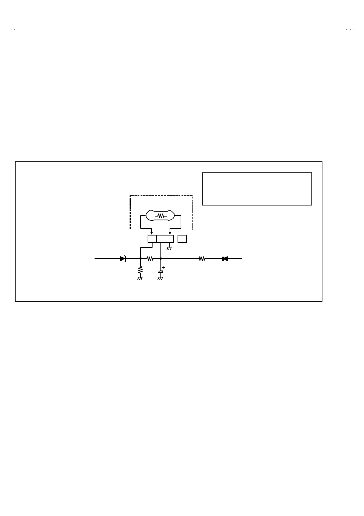
HOW TO CHECK THE HIGH VOLTAGE HOLD DOWN CIRCUIT
1. HIGH VOLT AGE HOLD DOWN CIRCUIT
After repairing the high voltage hold down circuit.
Thi s ci r cuit sh all b e ch ecked to op erat e co rrect ly .
2. CHECKING OF THE HIGH VOLTAGE HOLD DOWN CI RCUIT
(1) Turn the power switch on.
(2) As s hown i n fi g ure, s et th e r es ist or ( bet ween 【S1 】conne ctor 【2】an d【3】).
(3) Make sure t hat th e scr ee n pic ture disap pe ar s .
(4) Temporarily unplug the power plug.
(5) Remove the resistor (between【S1】co nnector【2】an d【3】).
(6) Ag ai n plug th e pow er pl u g, make su re th at t he norm al pi ctur e is displ ay ed on th e sc r ee n.
RESISTOR
RESISTOR
All model : 22.8kΩ±
NNECTOR
Ω±0.5% 1/4W
Ω±Ω±
34
No. 51950
 Loading...