

Page 1
52170200310
SERVICE MANUAL
COLOR TELEVISION
AV-34WP84 /ZA
TVCATV VCR
POWER
DVD
ASPECT
MULTI SCREEN
SPLIT
EZ SURF
INDEX
POP
FREEZE
SELECT
SWAP
INPUT1
V1
3
12
INPUT2
V2
456
INPUT3
7809
V3
INPUT4
RETURN
/TV
V4
THEATER
NATURAL
VIDEO
DIGITAL-IN
PRO
CINEMA
STATUS
D-IN
SLEEP TIMER
DISPLAY SOUND
LIGHT
i
MUTING C.C.
C.C.
CH
VOL
VOL
OK
CH
BACKMENU
VCR CHANNEL
VCR / DVD
PREV NEXT POWER
TV/VCR
REW
PLAY FF
REC
STOP PAUSE
OPEN/CLOSE STILL/PAUSE
TV
BASIC CHASSIS
SB4
TABLE OF CONTENTS
1 PRECAUTION. . . . . . . . . . . . . . . . . . . . . . . . . . . . . . . . . . . . . . . . . . . . . . . . . . . . . . . . . . . . . . . . . . . . . . . . . 1-3
2 SPECIFIC SERVICE INSTRUCTIONS. . . . . . . . . . . . . . . . . . . . . . . . . . . . . . . . . . . . . . . . . . . . . . . . . . . . . . 1-4
3 DISASSEMBLY . . . . . . . . . . . . . . . . . . . . . . . . . . . . . . . . . . . . . . . . . . . . . . . . . . . . . . . . . . . . . . . . . . . . . . 1-10
4 ADJUSTMENT . . . . . . . . . . . . . . . . . . . . . . . . . . . . . . . . . . . . . . . . . . . . . . . . . . . . . . . . . . . . . . . . . . . . . . . 1-16
5 TROUBLESHOOTING . . . . . . . . . . . . . . . . . . . . . . . . . . . . . . . . . . . . . . . . . . . . . . . . . . . . . . . . . . . . . . . . . 1-49
COPYRIGHT © 2003 VICTOR COMPANY OF JAPAN, LIMITED
No.52170
2003/10
Page 2
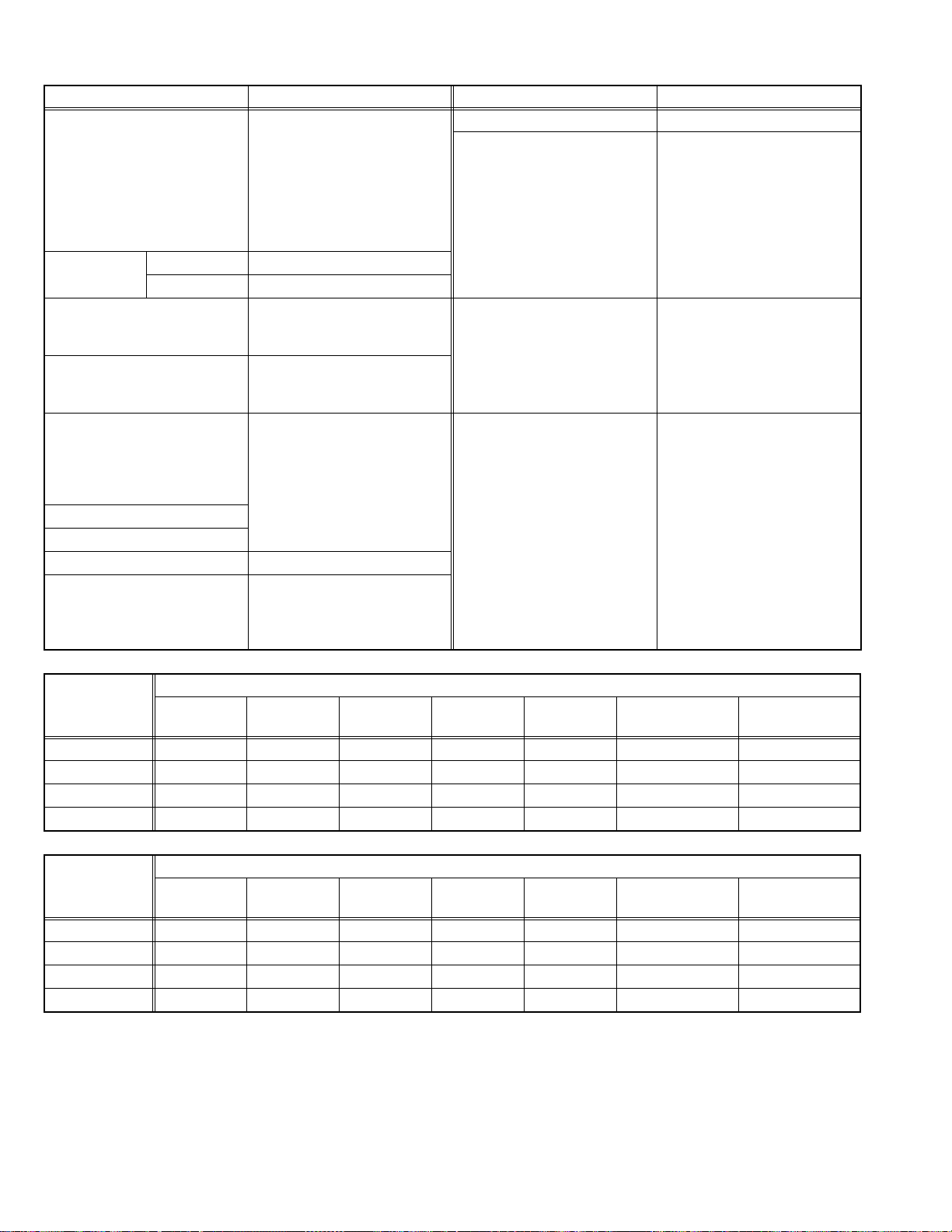
SPECIFICATION
Items Contents
Dimensions ( W × H × D ) 91.2cm × 62.4cm × 59.3cm (36" × 24-6/4" × 23-3/8")
Mass 74.0 kg (162.8 Ibs)
TV RF System CCIR (M)
Color System NTSC
Sound System BTSC (Multi Channel Sound)
TV Receiving Channels
and Frequency
TV / CATV Total Channel 180 Channels
Intermediate Frequency Video IF
Color Sub Carrier 3.58 MHz
Power Input AC120V , 60Hz
Power Consumption 229W (Max)
Picture Tube (Visible size) Full-Flat type, Aspect ratio 16:9 (Wide screen)
High Voltage 32kV+1kV/-1.3kV (at zero beam current)
Speaker 10cm (4"), round type × 2
Audio Power Output 10W × 10W
Antenna terminal (VHF/UHF) F-type connector, 75Ω unbalanced, coaxial
Video / Audio input S-Video
Component Video
Digital-in Video
Audio output
Subwoofer output More than 0 to 1000mV (rms) (+2.2dBs),
Speaker input 16Ω, 20W (rms)
AV compulink III 3.5mm mini jack × 1
Remote Control Unit RM-C11G (AA/R6/UM-3 battery × 2)
Design & specifications are subject to change without notice.
VHF Low
VHF High
UHF
CATV
Sound IF
[INPUT-1/3/4]
Video
Audio
[INPUT-1/2]
1125i / 750p
525p / 525i
Audio
Variable
Fix
02ch~06ch : 54MHz~88MHz
07ch~13ch : 174MHz~216MHz
14ch~69ch : 470MHz~806MHz
54MHz~804MHz
Low Band : 02~06, A-8 by 02~06&01
High Band : 07~13 by 07~13
Mid Band : A~I by 14~22
Super Band : J~W by 23~36
Hyper Band : W+1~W+28 by 37~64
Ultra Band : W+29~W+84 by 65~94, 100~125
Sub Mid Band : A4~A1 by 96~99
45.75 MHz
41.25 MHz (4.5MHz)
80cm (34") (Diagonally) H:43.0cm × W:75.9cm (17" × 30")
3cm × 10cm (1-1/2" × 4"), oval type × 2
Mini-DIN 4 pin × 3
Y: 1V (p-p), Positive (Negative sync provided), 75 Ω
C: 0.286V (p-p) (Burst signal), 75 Ω
1V (p-p), Positive (Negative sync provided), 75 Ω, RCA pin jack × 4
500mV (rms), High impedance, RCA pin jack × 8
RCA pin jack × 6
Y : 1V (p-p) (Sync signal: 0.35V(p-p), 3-value sync.), 75 Ω
Pb/Pr : 0.35V(p-p), 75 Ω
Y : 1V (p-p), Positive (Negative sync provided), 75 Ω
Pb/Pr : 0.35V(p-p), 75 Ω
DVI-D 24-pin connector × 1
(Digital-input terminal is not compatible with computer signal)
500mV (rms), Low impedance, RCA pin jack × 2
RCA pin jack × 2
More than 0 to 1000mV (rms) (+2.2dBs)
500mV(rms), (-4dBs), low impedance (400Hz when modulated 100%)
low impedance (400Hz when modulated 100%), RCA pin jack × 1
1-2 (No.52170)
Page 3
SECTION 1
PRECAUTION
1.1 SAFETY PRECAUTIONS
(1) The design of this product contains special hardware, many
circuits and components specially for safety purposes. For
continued protection, no changes should be made to the original
design unless authorized in writing by the manufacturer.
Replacement parts must be identical to those used in the original
circuits. Service should be performed by qualified personnel only.
(2) Alterations of the design or cir cuitry of the pr oducts shou ld n ot be
made. Any design alterations or additions will void the
manufacturer's warranty and will further relieve the manufacturer
of responsibility for personal injury or property damage resulting
therefrom.
(3) Many electrical and me chanical parts in the products have special
safety-related characteristics. These characteristics are often not
evident from visual inspection nor can the protection afforded by them
necessarily be obtained by using replacement components rated for
higher voltage, wattage, etc. Replacement parts w hich have these
special safety characteristics are identified in the parts list of Service
manual. Electrical components having such features are
identified by shading on the schematics and by ( ) on the
parts list in Service manual. The use of a substitute replacement
which does not have the same safety characteristics as the
recommended replacement part shown in the part s list of Service
manual may cause shock, fire, or other hazards.
(4) Use isolation transformer when hot chassis.
The chassis and any sub-chassis contained in some products are
connected to one side of the AC power line. An isolation
transformer of adequate capacity should be inserted between the
product and the AC power supply point while performing any
service on some products when the HOT chassis is exposed.
(5) Don't short between the LIVE side ground and ISOLATED (NEU-
TRAL) side ground or EARTH side ground when repairing.
Some model's power circuit is partly different in the GND. The difference of the GND is shown by the L IVE : ( ) side GND, the ISOLATED (NEUTRAL) : ( ) side GND and EARTH : ( ) side GND.
Don't short between the LIVE side GND and ISOLATED (NEUTRAL)
side GND or EARTH side GND and never measu re the LIVE side
GND and ISOLATED (NEUTRAL) side GND or EARTH side GND at
the same time with a measuring apparatus (oscilloscope etc.). If
above note will not be kept, a fuse or any parts will be broken.
(6) If any repair has been made to the chassis, it is recommended that
the B1 setting should be checked or adjusted (See B1 POWER
SUPPLY check).
(7) The high voltage applied to the picture tube must conform with that
specified in Service manual. Excessive high voltage can cause an
increase in X-Ray emission, arcing and possible component
damage, therefore operation under excessive high voltage
conditions should be kept to a minimum, or should be prevented.
If severe arcing occurs, remove the AC power immediately and
determine the cause by visual inspection (incorrect installation,
cracked or melted high voltage harness, poor soldering, etc.). To
maintain the proper minimum level of soft X-Ray emission,
components in the high voltage circuitry including the picture tube
must be the exact replacements or alternatives approved by the
manufacturer of the complete product.
(8) Do not check high voltage by drawing an arc. Use a high voltage
meter or a high voltage probe with a VTVM. Discharge the picture
tube before attempting meter connection, by connecting a clip lead
to the ground frame and connecting the other end of the lead
through a 10k
(9) When service is required, observe the original lead dress. Extra
precaution should be given to assure correct lead dress in the high
voltage circuit area. Where a short circuit has occurred, those
components that indicate evidence of overheating should be
replaced. Always use the manufacturer's replacement
components.
Ω 2W resistor to the anode button.
(10) Isolation Check (Safety fo r Electrical Shock Hazard)
After re-assembling the product, always perform an isolation
check on the exposed metal parts of the cabinet (antenna
terminals, video/audio input and output terminals, Control knobs,
metal cabinet, screw heads, earphone jack, control shafts, etc.) to
be sure the product is safe to operate without danger of electrical
shock.
a) Dielectric Strength Test
The isolation between the AC primary circuit and all metal parts
exposed to the user, particularly any exposed metal part having a
return path to the chassis should withstand a voltage of 1100V AC
(r.m.s.) for a period of one second.
(. . . . Withstand a voltage of 1100V AC (r.m.s.) to an appliance rat-
ed up to 120V, and 3000V AC (r.m.s.) to an appliance rated 200V
or more, for a period of one second.) This method of test requires
a test equipment not generally found in the service trade.
b) Leakage Current Check
Plug the AC line cord directly into the AC outlet (do not use a line
isolation transformer during this check.). Using a "Leakage
Current Tester", measure the leakage current from each exposed
metal part of the cabinet, particularly any exposed metal part
having a return path to the chassis, to a known good earth ground
(water pipe, etc.). Any leakage current must not exceed 0.5mA AC
(r.m.s.).
However, in tropical area, this must not exceed 0.2mA AC (r.m.s.).
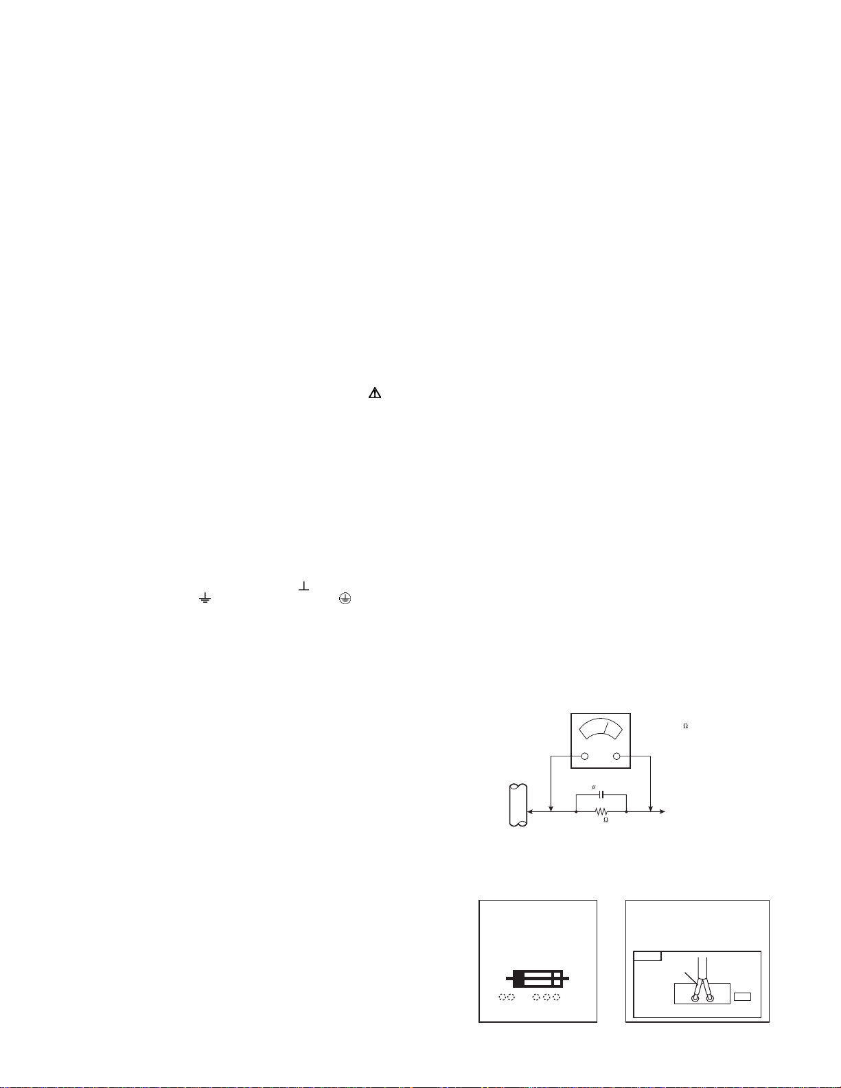
Alternate Check Method
Plug the AC line cord directly into the AC outlet (do not use a
line isolation transformer during this check.). Use an AC
voltmeter having 1000
following manner. Connect a 1500
a 0.15
µF AC-type capacitor between an exposed metal part
Ω per volt or more sensitivity in the
Ω 10W resistor paralleled by
and a known good earth ground (water pipe, etc.). Measure the
AC voltage across the resistor with the AC voltmeter. Move the
resistor connection to each exposed metal part, particularly any
exposed metal part having a return path to the chassis, and
measure the AC voltage across the resistor. Now, reverse the
plug in the AC outlet and repeat each measurement. Any
voltage measured must not exceed 0.75V AC (r.m.s.). This
corresponds to 0.5mA AC (r.m.s.).
However, in tropical area, this must not exceed 0.3V AC
(r.m.s.). This corresponds to 0.2mA AC (r.m.s.).
AC VOLTMETER
(HAVING 1000 /V,
OR MORE SENSITIVITY)
0.15 F AC-TYPE
PLACE THIS PROBE
1500 10W
(11) High voltage hold down circuit check.
GOOD EARTH GROUND
ON EACH EXPOSED
METAL PART
After repair of the high voltage hold down circuit, this circuit shall
be checked to operate correctly.See item "How to check the high
voltage hold down circuit".
This mark shows a fast
operating fuse, the
letters indicated below
show the rating.
A V
POWER CORD
REPLACEMENT WARNING.
Connecting the white line side of power
cord to "WHT" character side.
PWB
White line side
WHT
PW
(No.52170)1-3
Page 4
SECTION 2
SPECIFIC SERVICE INSTRUCTIONS
2.1 FEATURES
Multi screen function
• POP (Picture out Picture)
Back programs can be seen at once. Three programs are
displayed on screen right-hand side besides the program
(VHF/ UHF/ CATV) received now.
• INDEX
A favorable program can be selected from the 12 previews on
the screen.
• SPLIT
Different images, such as a program and video, can be
simultaneously seen on two screens.
Provided with 2 tuners and 2 aspect (16:9 & 4:3) mode.
Multifunctional remote control permits picture adjustment.
The CH.GUARD function prevents the specific channels from
being selected, unless the "ID number" is entered.
I2C bus control utilizes single chip ICs.
Adoption of the VIDEO STATUS function.
• The VIDEO STATUS key gives you a choice of 4 picture
display settings, including a display of your own preferences.
STANDARD DYNAMIC THEATER GAME
Digital-in
To receive digital broadcasts.
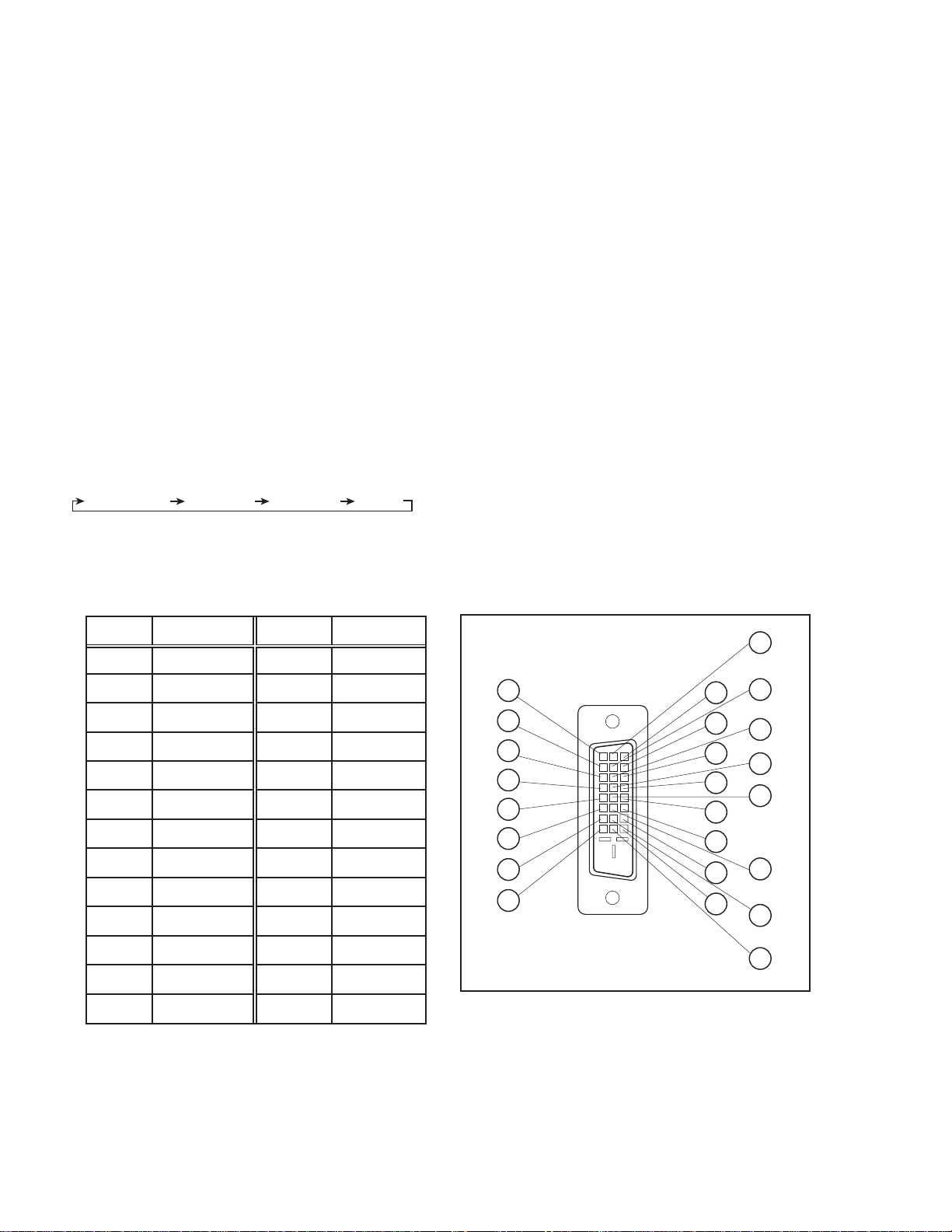
2.2 DIGITAL-IN TERMINAL FUNCTIONS
Digital-in will display when any picture signal (480i/ 480p,
720p/ 1080i) in Digital-in is displayed.
Natural Cinema
Watching the movie or animation, press the Natural Cinema to
adjust the out line of the images to make thin more sharp.
Built-in V-CHIP system.
• This TV is equipped with V-CHIP technology which enables TV
parental guidelines and movie guideline controls.
Closed-caption broadcasts can be viewed.
Built-in MTS (Multi-channel Television Sound) system.
In addition to mono or stereo sound, an MTS broadcast may
also include a Second Audio Program (SAP).
Built-in A.H.S system & BBE sound system.
S-VIDEO input terminal for taking best advantage of Super
VHS.
3D Digital comb filter improves picture quality.
Plug-in menu
The plug-in menu comes up automatically when you first turn
on the TV after plugging it in.
Pin No.
1
2
3
4
5
6
7
8
9
10
11
12
13
Pin name
RX2-
RX2+
GND2/ 4
RX4-
RX4+
SCL
SDA
NC
RX1-
RX1+
GND1/3
RX3-
RX3+
Pin No.
14
15
16
17
18
19
20
21
22
23
24
Pin name
5V
GND
HTPLG
RX0-
RX0+
GND0/5
RX5-
RX5+
GNDC
TXC+
TXC-
PIN ASSIGNMENTPIN NAME
9
17
18
19
20
10
1
2
11
3
12
4
13
21
22
23
24
5
6
14
7
8
15
16
1-4 (No.52170)
Page 5
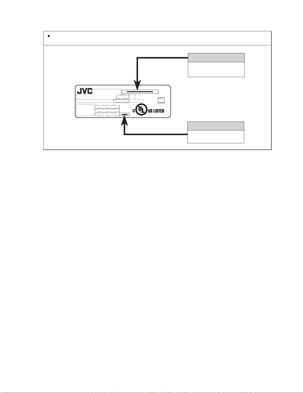
2.3 HOW TO IDENTIFY MODELS
How to recognize from the appearance of the model concerned is written below. Please distinguish from several contents
currently printed on the rating label.
MODEL NAME
AV-34WP84
AC 120V 60Hz
MODEL NO.
TV SCREEN SIZE : DIAGONAL
CHASSIS NO.
MANUFACTURED
SERIAL NO.
W
INCHES
ME
VIDEO EQUIPMENT
4C43
DISTINGUISH NAME
ZA
(No.52170)1-5
Page 6
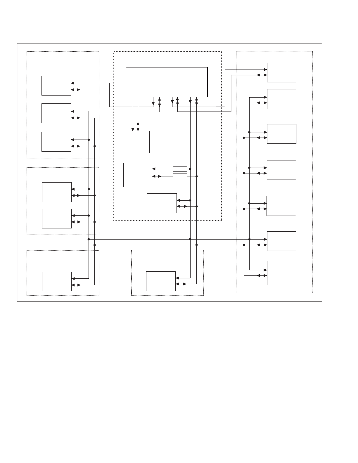
2.4 TECHNICAL INFORMATION
2.4.1 SYSTEM BLOCK DIAGRAM
RECEIVER PWB
IC0201
MTS/VOL/
TONE
TU0102
MAIN U/V
TUNER
SCL2
SDA2
SCL0
SDA0
MI-COM & DIST MODULE PWB
IC1701
MI-COM
SCL4
SDA4
SCL2
SDA2
SCL1
SDA1
SCL0
SDA0
MAIN PWB
SCL1
SDA1
SCL0
SDA0
IC1703
MEMORY
TU1101
SUB U/V
TUNER
IC0701
LATCH
DEF OSC PWB
IC0161
DEF
CORRECTION
IC0212
LATCH
FRONT CONTROL
PWB
IC1704
LATCH
SCL0
SDA0
SCL0
SDA0
SCL0
SDA0
SCL4 SDA4
IC1001
DIST
PROCESS
IC3001
3D Y/C SEP &
CHROMA
DECODER
DIGITAL INPUT
MODULE PWB
SCL3
SDA3
IC1301
RGB
PROCESSOR
IC001
FORMAT
CONVERT
Q1713
Q1712
SCL0
SDA0
SCL0
SDA0
SCL0
SDA0
IC1211
SYNC
SW/DET.
IC1301
COMPONENT
SW
IC1501
AV
SELECT
IC1502
LATCH
IC3001
2D Y/C SEP &
CHROMA
DECODER
1-6 (No.52170)
Page 7
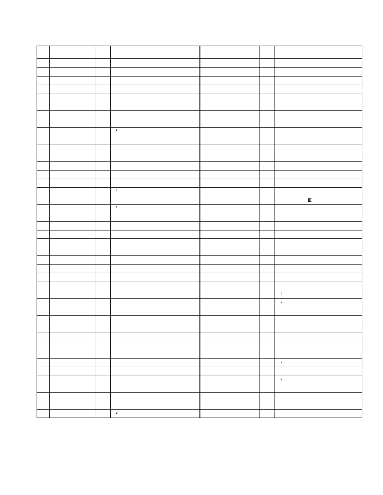
2.4.2 MAIN MICRO COMPUTER (CPU) FUNCTION
(MN102H75KPD)
Pin
No.
1
2
3
4
5
6
7
8
9
10
11
12
13
14
15
16
17
18
19
20
21
22
23
24
25
26
27
28
29
30
31
32
33
34
35
36
37
38
39
40
41
42
Pin name Function
NC
/VSYNC
LB_PRO
NC
/RST
NC
/TEST
YS
SDA4
NC
A_MUTE
/HSYNC
NC
OSDXI
OSDXO
SDA2
AC_IN
SCL2
/TU_POW
VCOI
PDO
/IP_RESET
YM
B
LED_POWER
G
R
VREF
IP_ERR
IREF
COMP
AVD D
CLL
VREFLS
SUB_CCD
NC
VSS
MAIN_CCD
VREFHS
CLH
VDD
SCL4
I/O
O
NC
I
V. sync for OSD
I
Low B protect detection [Detect : H]
-
NC
I
CPU reset [Reset : L]
NC
O
I
Operation test for CPU
Ys (blanking) for OSD
O
I/O
I C bus (data) for DIST
NC
O
Audio muting [Muting :H]
O
I
H.sync for OSD
NC
O
I
Keep for OSD oscillation
I
Keep for OSD oscillation
I/O
I C bus(data) for MTS
I
AC(60Hz) for timer clock
O
I C bus (clock) for MTS
O
NC
I
LPF
O
LPF
O
Reset for DIST [Reset : L]
O
YM (transparence) for OSD
O
OSD blue
O
Lighting for POWER LED [Lighting : H]
O
OSD green
O
OSD red
I
Reference voltage for OSD
I
AMDP program load error detection
I
Reference current for OSD
I
Phase adjust for OSD
+3.3V
I
For Low clamp level
I
Reference voltage in for sub CCD
I
Composite video for sub CCD
I
-
NC
GND
I
I
Composite video for main CCD
I
Reference voltage in for main CCD
I
For High clamp level
I
+3.3V
I C bus (clock) for DIST
O
Pin
No.
43
CLK_SW
44
LED_ON_TIMER
45
NC
46
NC
47
SBT1
48
NC
49
NC
50
NC
51
NC
52
ABL/ACL
53
CHROME
54
DC_COTL
55
NC
56
NC
57
AFC_1
58
/LOB_POW
59
/COMPLINK
60
/POWERGOOD
61
/MECA_ON
62
/MAIN_POW
63
NC
64
/B1_POW
65
AFC2
66
X-RAY
67
NC
68
KEY2
69
KEY1
70
SCL1
71
SDA1
72
REMO
73
NC
74
VSS
75
OSC2
76
OSC1
77
VDD
78
SCL0
79
NC
80
SDA0
81
NC
82
NC
83
NC
84
P MUTE
Pin name Function
I/O
O
IP clock switch control
O
NC
O
NC
I
NC
I
Use for on board writing [for factory]
NC
O
O
NC
NC
O
O
NC
ABL/ACL control
O
O
Chroma / Gamma control
O
Black level DC reproduce control
O
NC
O
NC
I
Sub AFT voltage
O
LOB power control [Power on : L]
I
AV compulink control
I
Power condition check
I
Power SW interrupt [Pushing :L]
O
Main power control [Power on : L]
-
NC
O
B1 power control [Power on : L]
I
Main AFT voltage
I
X-ray protect detection [Protect : 0.7v]
I
NC
I
Key scan for front key (CH+,Vol-/+)
I
Key scan for front key (Menu,CH-)
O
I C bus (clock) for main memory
I/O
I C bus (data) for main memory
I
Remote control
O
NC
I
GND
O
System clock oscillation (4MHz)
I
System clock oscillation (4MHz)
I
+3.3V
O
I C bus (clock) for generally
O
NC
I/O
I C bus (data) for generally
O
NC
I
NC
-
NC
O
Picture muting
(No.52170)1-7
Page 8
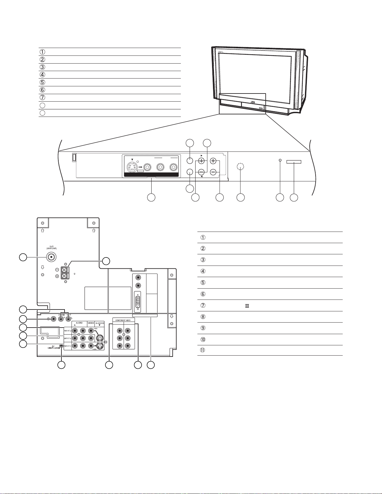
2.5 FUNCTIONS z FRONT PANEL
INPUT-4 terminals(S-video,Video,Audio L/MONO /R)
INPUT-4 button
MENU button
CHANNEL -/+ buttons
VOLUME -/+ buttons
POWER & ON TIMER lamp
POWER(Main) button
8
Sensor (for remote control unit)
Operate button (for MENU)
9
9
3
z AV TERMINAL (REAR)
1
SPEAKER INPUT
16 20W RMS
2
3
SUBWOOFER
OUT
4
5
6
S-VIDEO
OVER
VIDEO
INPUT 4
AUDIO
L/MONO R
INPUT 4
CHANNEL VOLUMEMENU
ON TIMER
POWER
2
1
Antenna (VHF/UHF) terminal
AUDIO OUT (L/R) terminal
11
R
AUDIO
L
VIDEO
DIGITAL-IN
L
INPUT-1INPUT-2
Y
Y
Pb
Pb
Pr
Pr
SUBWOOFER OUT terminal
INPUT-3 terminal (S-video / Video /Audio L/R)
INPUT-2 terminal (Video/Audio L/R)
INPUT-1 terminal (S-video / Video /Audio L/R)
AV COMPULINK terminal
COMPONENT VIDEO INPUT-2 terminal (Y/Pb/Pr)
COMPONENT VIDEO INPUT-1 terminal (Y/P
DIGITAL-IN terminal [Video(DVI 24pin), Audio L/R]
SPEAKER INPUT terminal
85
64
7
b/Pr
)
1-8 (No.52170)
7 8 9 10
Page 9
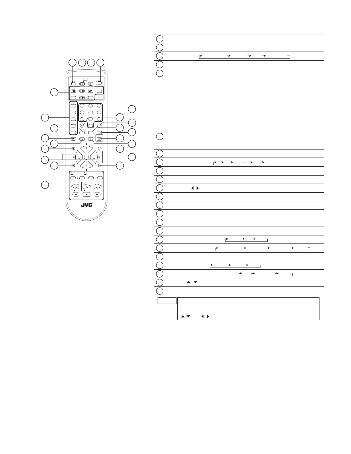
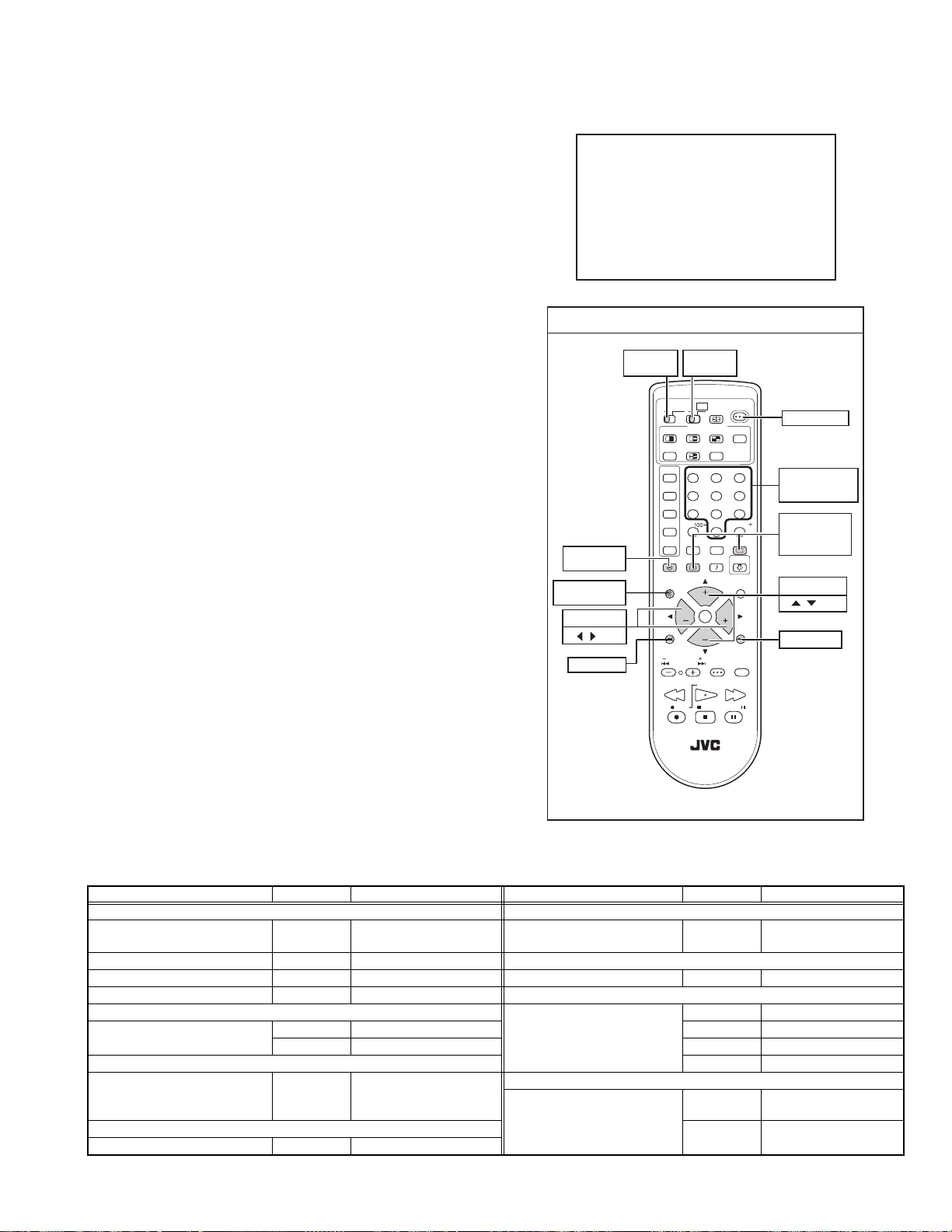
z REMOTE CONTROL (RM-C11G)
1 2 3 4
10
11
13
TV CATV VCR
5
6
7
8
9
SPLIT
FREEZE
INPUT1
V1
INPUT2
V2
INPUT3
V3
INPUT4
V4
DIGITAL-IN
D-IN
SLEEP TIMER
DISPLAY SOUND
MUTING C.C.
VOL
12
VCR CHANNEL
PREV NEXT POWER
REW
REC
OPEN/CLOSE STILL/PAUSE
POWER
DVD
ASPECT
MULTI SCREEN
EZ SURF
INDEX
POP
SELECT
SWAP
12
456
7809
RETURN
THEATER
NATURAL
VIDEO
PRO
CINEMA
STATUS
LIGHT
i
CH
VOL
OK
CH
BACKMENU
VCR / DVD
TV/VCR
PLAY FF
STOP PAUSE
TV
3
/TV
C.C.
15
17
19
21
23
14
16
18
20
22
1
TV / CATV switch
2
VCR / DVD switch
ASPECT key:
3
4
POWER key
MULTI SCREEN key:
5
PANORAMA CINEMA FULL REGULAR
SPLIT key: 2 screen mode can be displayed.
POP key: 3 separate pictures can be displayed on the right side of the main picture.
INDEX key: 12 screen mode
EZ SURF key:
FREEZ key: The still picture can be displayed.
Back program can be displayed.
can be displayed.
SWAP key: In SPLIT mode, the channel displayed in the split screen window can be
exchanged for the main screen.
SELECT key: The picture can be selected while viewing POP or SPLIT screen.
Input select keys:
6
(INPUT1, INPUT2, INPUT3, INPUT4, DIGITAL-IN)
THEATER PRO key
7
SLEEP TIMER key:
8
DISPLAY key
9
MUTING key (memory key
10
VOL+/- & /
11
MENU key
12
VCR / DVD control keys
13
Channel number keys
14
15
100+ key
RETURN+/TV key
16
NATURAL CINEMA
17
VIDEO STATUS key:
18
LIGHT key
19
SOUND key:
20
C.C. (CLOSED CAPTION) key:
21
CH+/- & /
22
BACK key
23
NOTE
The CH+/- keys and VOL+/- keys operate CHANNEL and
0 15 30 165 180
for SERVICE MENU
(for SERVICE MENU)
AUTO ON OFF
key:
keys
)
STANDARD DYNAMIC THEATER GAME
MOVIE MUSIC OFF
A.H.S: and BBE ON/OFF can be set
OFF CAPTION TEXT
(for SERVICE MENU)
keys
VOLUME normally.
These keys are also used to navigate SERVICE MENU as the
/ and / keys.
(No.52170)1-9
Page 10
SECTION 3
DISASSEMBLY
3.1 DISASSEMBLY PROCEDURE
3.1.1 REMOVING THE REAR COVER
• Unplug the power supply cord.
(1) Remove the 16 screws [A] as shown in Fig.1.
(2) Remove the REAR COVER toward you.
NOTE:
When reinstalling the REAR COVER, carefully push it inward
after inserting the chassis into the REAR COVER groo ve .
3.1.2 REMOVING THE AV TERMINAL BOARD
• Remove the REAR COVER.
(1) Remove the 7 screws [B] as shown in Fig.1.
(2) When you pull out the AV TERMINAL BOARD in the
direction of arrow [a] as shown in Fig.1, it can be removed.
3.1.3 REMOVING THE CHASSIS
• Remove the REAR COVER.
(1) Slightly raise the both sides of the CHASSIS by hand and
remove the 2 claws under the both sides of the CHASSIS
from the front cabinet.
(2) Draw the CHASSIS backward along the rail in the arrow
direction [a] as shown in Fig.1.
(If necessary, take off the wire clamps, connectors etc.)
NOTE:
When conducting a check with power supplied, be sure to
confirm that the CRT earth wire is connected to the CRT
SOCKET PWB and MAIN PWB or DEF & POWER PWB.
3.1.4 REMOVING THE CONTROL BASE
• Remove the REAR COVER.
Remove the CHASSIS.
(1) While pushing down the claws [b] as shown in Fig.2.
(2) Remove the CONTROL BASE in the arrow direction
marked [c].
( If necessary, take off the wire clamps, connectors etc. )
3.1.5 REMOVING THE DIGITAL INPUT MODULE PWB
• Remove the REAR COVER
• Remove the AV TERMINAL BOARD.
(1) Remove the 2 screws [C] as shown in Fig.1.
(2) Remove the DIGITAL INPUT MODULE PWB in the arrow
direction [d].
NOTE:
If necessary, take off the wire clamps, connectors etc.
3.1.6 REMOVING THE DOME SPEAKER BOX
• Remove the REAR COVER.
(1) Remove the 2 screws [D] as shown in Fig.1.
(2) Remove the DOME SPEAKER BOX toward you.
(3) Follow the same steps when removing the other hand
speaker.
3.1.7 REMOVING THE SPEAKER / SPEAKER HOLDER
• Remove the REAR COVER.
• Remove the DOME SPEAKER BOX
(1) Remove the 2 screws [E] as shown in Fig.1.
(2) Remove the SPEAKER HOLDER toward you.
(3) Remove the 2 screws [F] as shown in Fig.1.
(4) Draw the SPEAKER toward you.
(5) Follow the same steps when removing the other hand
SPEAKER.
3.1.8 CHECKING THE PW BOARD
• To check the backside of the circuit board.
(1) Pull out the CHASSIS. (Refer to REMOVING THE
CHASSIS).
(2) Erect the CHASSIS vertically so that you can easily check
the backside of the PW Board.
CAUTION:
• When erecting the CHASSIS, be careful so that there will be
no contact with other PWB.
• Before turning the power on, make sure that the CRT earth
wire and other connectors are properly connected.
3.1.9 WIRE CLAMPING AND CABLE TYING
(1) Be sure to clamp the wire.
(2) Never remove the cable tie used for tying the wires
together.
Should it be inadvertently removed, be sure to tie the wires
with a new cable tie.
DIGITAL INPUT MODULE
POWER CORD
1-10 (No.52170)
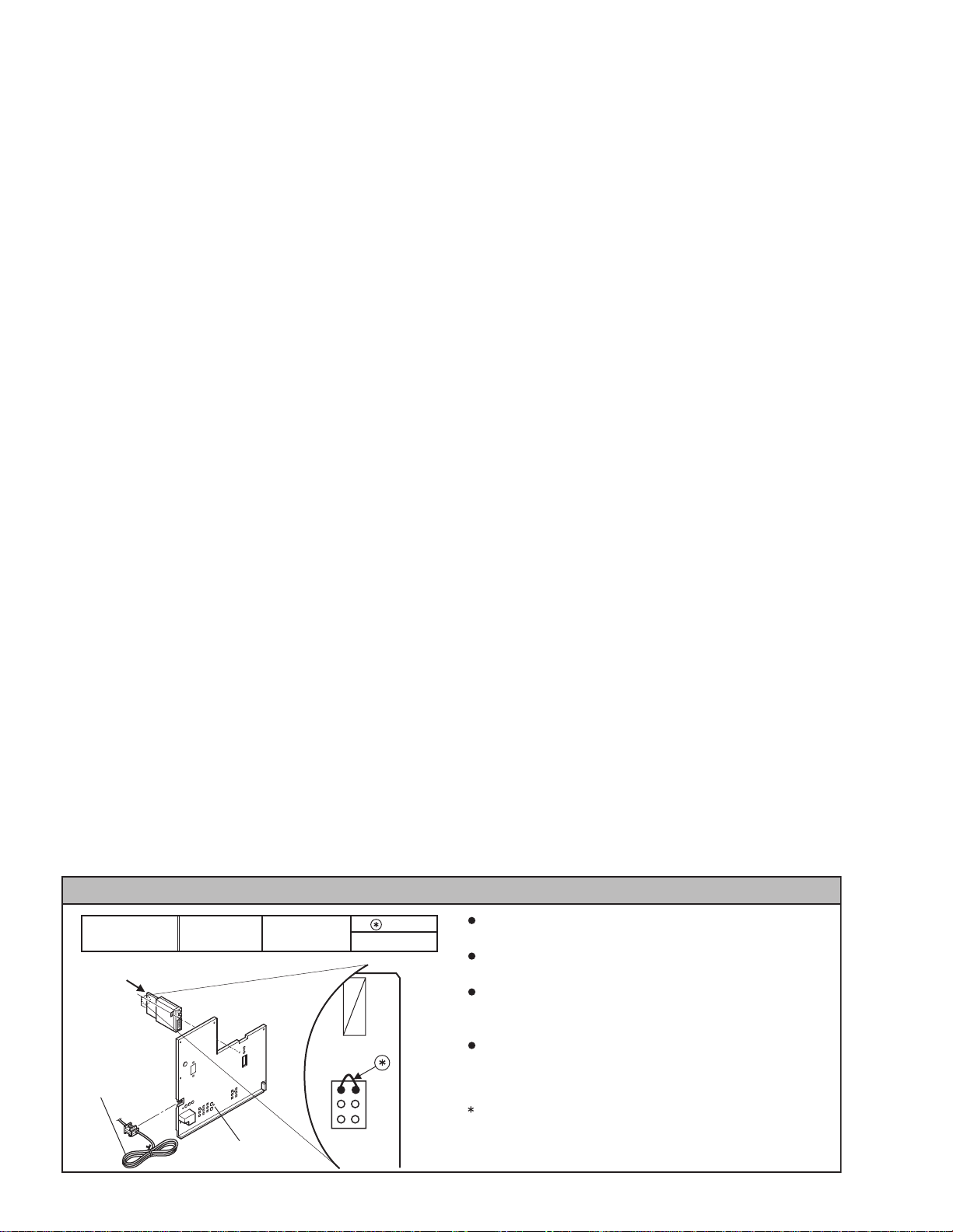
CAUTION AT DISASSEMBLY
SSB-7976A-M2AV-34WP84/ZA 34WP84CP-S
AV TERMINAL
BOARD
1
3
5
SB
connector
wire
WJJ0247-001A
2
4
6
Prior to disassembly, unplug the power cord from the wall
outlet without fail. (Turn the power “off”.)
Short the SB connector (1) pin and (2) pin of the digital input
unit. (At the time of assembling)
Before the rear cover is inserted into the cabinet, release the
short-circuit between the SB connector (1) pin and (2) pin of
the digital input unit.
After releasing the short-circuit between the SB connectors,
do not turn the power on until the rear cover is inserted into
the cabinet.
Negligence in carrying out the above steps may cause the
inactivation of the TV.
Page 11
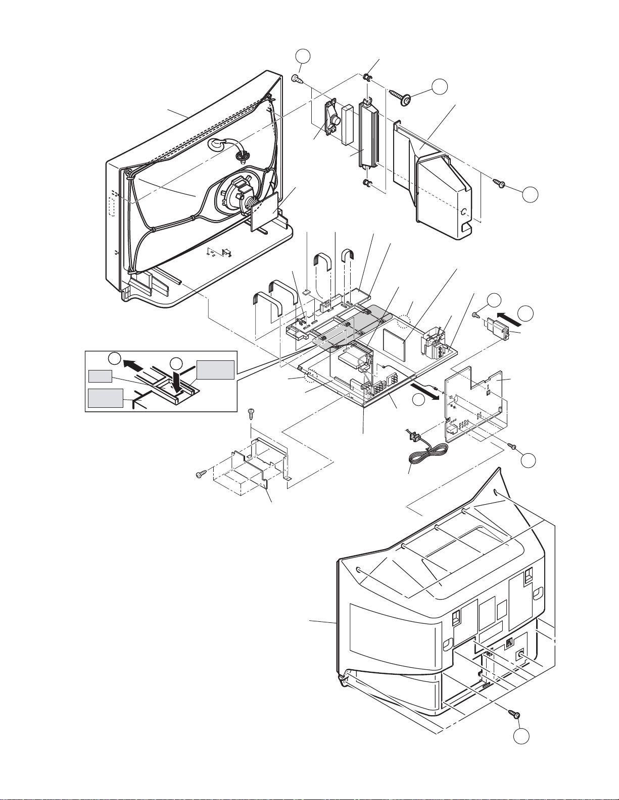
FRONT CABINET
c
CLAW
CHASSIS
BASE
Fig. 2
b
CONTROL
BASE
SPEAKER
CRT
SOCKET
PWB
FRONT
SENSOR
PWB
FRONT
CONTROL
PWB
CLAW
MAIN PWB
F
( x 4)
SPEAKER
HOLDER
FRONT
SW
PWB
RECEIVER
PWB
SPACER
FRONT
JACK
PWB
CHASSIS
BASE
( x 4)
E
CONTROL
BASE
MI-COM &
DIST MODULE
PWB
CLAW
a
( x 4)
DOME
SPEAKER
BOX
DEF OSC PWB
DEF & POWER
PWB
FBT
( x 2)
C
D
( x 4)
d
DIGITAL
INPUT
MODULE
PWB
AV TERMINAL
BOARD
B
( x 7)
LINE FILTER
PWB
REAR COVER
Fig.1
POWER CORD
A
( x 16)
(No.52170)1-11
Page 12
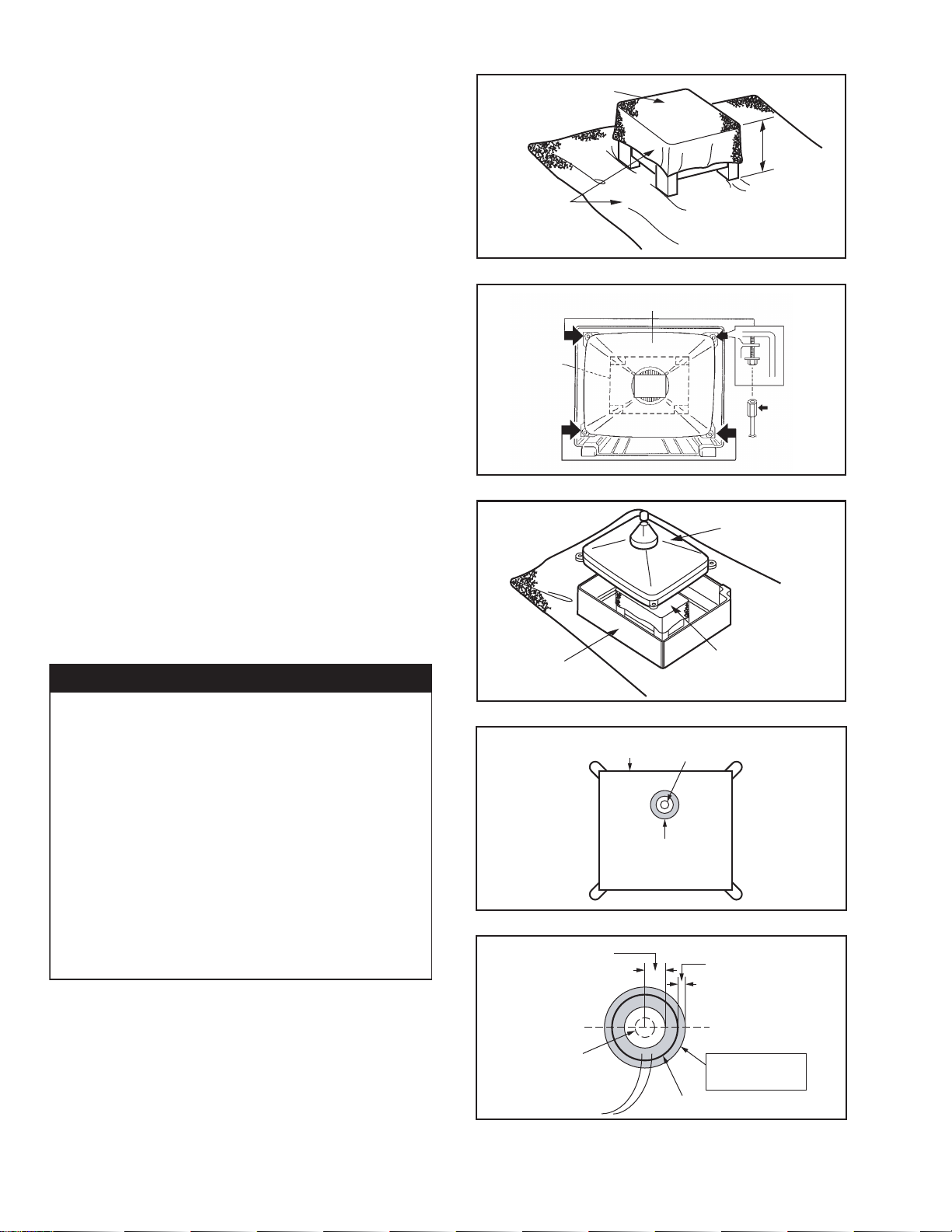
3.1.10 REMOVING THE CRT (PICTURE TUBE)
NOTE:
• Replacement of the CRT should be performed by 2 or more
persons.
• After removing the REAR COVER, CHASSIS etc.,
(1) Putting the CRT change table on soft cloth, the CRT
change table should also be covered with such soft clo th
(shown in Fig. 3).
(2) While keeping the surface of CRT down, mount the TV set
on the CRT change table balanced will as shown in Fig. 3.
(3) Remove 4 screws marked by arrows with a box type
screwdriver as shown in Fig. 4.
NOTE:
Since the cabinet will drop when screws have been
removed, be sure to support the cabinet with hands.
(4) After 4 screws have been removed, put the cabinet slow ly
on cloth (At this time, be carefully so as not to damage the
front
surface of the cabinet) shown in Fig. 5.
NOTE:
• The CRT should be assembled according to the
opposite sequence of its dismounting steps.
• The CRT change table should preferably be smaller
that the CRT surface, and its height be about 35cm.
COATING OF SILICON GREASE FOR ELECTRICAL INSULATION ON THE CRT ANODE CAP SECTION.
Subsequent to replacement of the CRT and HV transformer or
repair of the anode cap, etc. by dismounting them, be sure to
coat silicon grease for electrical insulation as shown in
Fig.6.Wipe around the anode button with clean and dry cloth.
(Fig.6)Coat silicon grease on the section around the anode
button. At this time, take care so that any silicon greases dose
not sticks to the anode button. (Fig.7)
CAUTION FOR DEGAUSSING WORKS
Whenever degaussing works are required due to distorted
images and colors caused by the replacement of the CRT
or other external magnetic forces, self-degaussing (internal
degaussing) should be carried out without fail instead of
degaussing the monitor from the outside.
Because of the characteristics of the CRT used in this
monitor , the distorted images and colors may worsen if
degaussing the monitor from the outside has been
performed.
Even if external degaussing works have been carried out,
self-degaussing should be performed by turning the power
on the monitor.
When you want to perform self-degaussing of the monitor
whose power is already turned on, turn of f the power and
wait for about 10 minutes before turning the power on the
monitor again for self-degaussing.
CRT CHANGE TABLE
CLOTH
Fig.3
CRT
CRT
CHANGE
TABLE
Fig.4
CABINET
CRT
CHANGE T ABLE
Fig.5
Silicon grease product No. KS - 650N
CRT
Anode button
Silicon grease
coating
Fig.6
Approx.
20mm (Do not
coat grease on
this section
Silicon grease
should be coated
by 5mm or more
from the outside
diameter of anode
cap.
CRT
APPROX.
35cm
BOX
TYPE
SCREW
DRIVER
1-12 (No.52170)
Anode button
(No sticking of
silicon grease)
Fig.7
Coating position
of silicon grease
Anode cap
Page 13
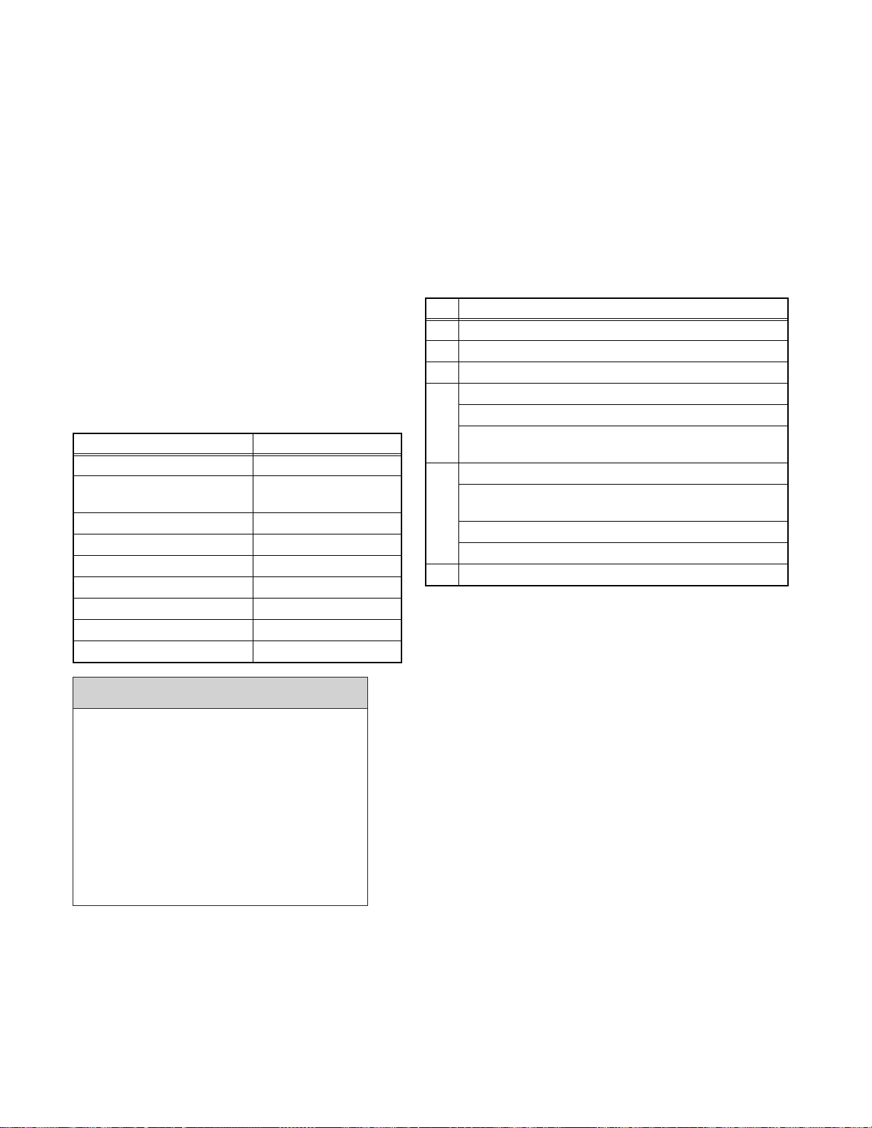
3.2 MEMORY IC REPLACEMENT
3.2.1 MEMORY IC
This model uses a memory IC.
This memory IC stores data for proper operation of the video and
SERVICE MENU
deflection circuits.
When replacing the memory IC, be sure to use an IC containing
this (initial value) data.
3.2.2 MEMORY IC REPLACEMENT PROCEDURE
(1) Power off
1. PICTURE/SOUND
2. YC SEP
3. WHITE BALANCE
4. MEMORY SETUP
5. RF AFC
6.
7.
8. IP
9. DSD
0. HDMI
Switch the power off and disconnect the power cord from
the wall outlet.
(2) Replace the memory IC
Initial value must be entered into the new IC.
(3) Power on
Connect the power cord to the wall outlet and switch the
SERVICE MENU SELECT KEY
Fig.1
power on.
(4) SERVICE MENU setting
Before entering the SERVICE MENU, confirm that the
setting of TV/CATV SW of the REMOTE CONTROL UNIT
is at the "TV" side and the setting of VCR/DVD SW of the
REMOTE CONTROL UNIT is at the "VCR" side. If the
switches have not been properly set, you cannot enter the
SERVICE MENU.
a) Press [SLEEP TIMER] key and while the indication of
SLEEP TIMER 0 MIN is being displayed, press
[DISPLAY] key and [VIDEO STATUS] key on the
remote control unit (Fig.2) simultaneously.
b) The SERVICE MENU screen as shown in Fig.1 is
displayed.
c) Verify what to set in th e SERVICE MENU, and set
whatever is necessary (Fig.1).
Refer to the SERVICE ADJUSTMENT for setting.
d) Press the [BACK] key twice to return normal screen.
(5) Receive channel setting
Refer to the OPERATING INSTRUCTIONS (USER'S
GUIDE) and set the receive channels (Channels Preset) as
described.
(6) User settings
SLEEP
TIMER key
MEMORY key
(MUTING)
Set value
/ key
MENU key
TV/CATV
switch
VCR/DVD
switch
TV CATV VCR
SPLIT
FREEZE
INPUT1
V1
INPUT2
V2
INPUT3
V3
INPUT4
V4
DIGITAL-IN
D-IN
SLEEP TIMER
DISPLAY SOUND
MUTING C.C.
VOL
VCR CHANNEL
PREV NEXT POWER
REW
REC
OPEN/CLOSE STILL/PAUSE
DVD
ASPECT
MULTI SCREEN
INDEX
POP
SELECT
SWAP
12
456
7809
THEATER
NATURAL
PRO
CINEMA
i
CH
VOL
OK
CH
VCR / DVD
PLAY FF
STOP PAUSE
POWER
EZ SURF
RETURN
VIDEO
STATUS
LIGHT
BACKMENU
TV/VCR
3
/TV
C.C.
POWER key
CHANNEL
NUMBER keys
DISPLAY &
VIDEO
STATUS key
Select item
/ key
BACK key
Check the user setting items according to the steps
described in the after page.
Where these do not agree, refer to the OPERATING
RM-C11G
TV
INSTRUCTIONS (USER'S GUIDE) and set the items as
described.
Fig.2
3.3 FACTRY SETTING VALUE
3.3.1 SERVICE MENU SETTING MODE
Setting Item Settings Item No. Setting Item Settings Item No.
1.PICTURE/SOUND (SOUND AND PICTURE SETTING) 5.RF AFC
Sound circuits (A) Fixed A01~A27 IF VCO adjustment Adjust
Video circuits (S) Adjust S01~S99 8.IP
Deflection circuits (D) Adjust D01~D32 DIST processing setting Fixed IPA001~IPA042
Factory setting items (F) Adjust F01~F70 9.DSD
2.YC SEP
YC separation setting
Fixed YCM001~YCS114 Fixed DSB001~DSB053
Fixed YCM001~YCS114 Fixed DSC001~DSC044
Digital super detail setting
Fixed DSA001~DSA053
3.WHITE BALANCE Fixed DSD001~DSD017
0.HDMI
White balance adjustment AdjustBRDRV R, DRV B
CUT R, CUT G, CUT B
Digital input processing setting
Fixed HDM001~HDM080
4.MEMORY SETUP Fixed RHD001~RHD170
Memory data edit Non adjust ---
Refer to adjustment
Procedure
(No.52170)1-13
Page 14
3.3.2 FACTORY SETTING
Setting item Setting value Setting item Setting value
POWER
CHANNEL
VOLUME
INPUT
DISPLAY
NATURAL CINEMA
ASPECT MODE
VIDEO STATUS
SOUND A.H.S OFF
BBE ON
SPLIT SOURCE Left side: CA-02
POP SOURCE Right upper corner: CA-04
TINT
COLOR
PICTURE
BRIGHT
DETAIL
COLOR TEMPERATURE
DIG. NOISE CLEAR
VSM(Velocity scan modulation) ON
BASS
TREBLE
BALANCE
MTS
NTSC/ 480i / 480p system
Item
STANDARD 00 00 00 00 00 LOW OFF
DYNAMIC 00 00 +30 00 +30 HIGH OFF
THEATER 00 00 00 00 00 LOW OFF
GAME 00 00 -10 00 00 HIGH OFF
1080i / 720p system
Item
STANDARD 00 00 00 00 00 LOW OFF
DYNAMIC 00 00 +30 00 00 HIGH OFF
THEATER 00 00 00 00 00 LOW OFF
GAME 00 00 -10 00 00 HIGH OFF
TINT COLOR PICTURE BRIGHT DETAIL
TINT COLOR PICTURE BRIGHT DETAIL
Off
CABLE-02
10
TV
Off
AUTO
REGULAR
DYNAMIC
Right side: CA-04
Left side: CA-02
Right center side: CA-05
Right bottom corner: CA-07
Refer to the following table
Center (00)
Center (00)
Center (00)
STEREO
ON / OFF TIMER NO
TV SPEAKER
AUDIO OUT
CENTER CH INPUT
DIGITAL-IN
NOISE MUTING
FRONT PANEL LOCK
V1 SMART INPUT
LANGUAGE
CLOSED CAPTION
AUTO SHUT OFF
XDS ID
TILT CORRECTION
PURITY
V-CHIP
SET LOCK CODE
AUTO DEMO
Setting value
Setting value
ON
FIX
NO
SIZE 1
ON
OFF
OFF
ENG
OFF ( CC1 / T1 )
OFF
OFF
Center
Center
OFF
(0000)
OFF
COLOR
TEMPERATURE
COLOR
TEMPERATURE
DIGI. NOISE
CLEAR
DIGI. NOISE
CLEAR
1-14 (No.52170)
Page 15
3.4 REPLACEMENT OF CHIP COMPONENT
3.4.1 CAUTIONS
(1) Avoid heating for more than 3 seconds.
(2) Do not rub the electrodes and th e resist parts of the pattern.
(3) When removing a chip part, melt the solder adequately.
(4) Do not reuse a chip part after removing it.
3.4.2 SOLDERING IRON
(1) Use a high insulation soldering iron with a thin pointed end of it.
(2) A 30w soldering iron is recommended for easil y removing parts.
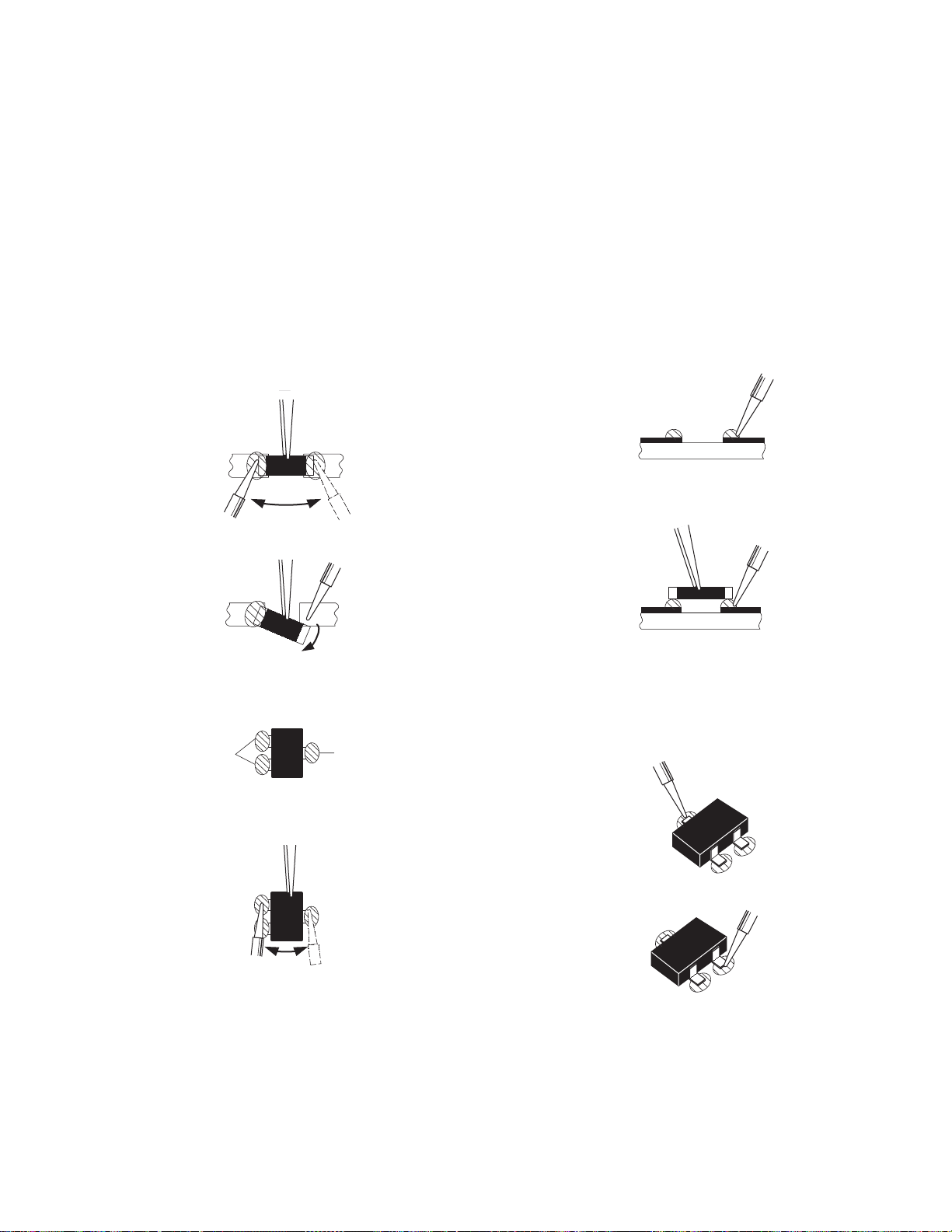
3.4.3 REPLACEMENT STEPS
1. How to remove Chip parts
2. How to install Chip parts
[Resistors, capacitors, etc.]
(1) As shown in the figure, push the part with tweezers and al-
ternately melt the solder at each end.
(2) Shift with the tweezers and remove the chip part.
[Transistors, diodes, variable resistors, etc.]
(1) Apply extra solder to each lead.
SOLDER
SOLDER
[Resistors, capacitors, etc.]
(1) Apply solder to the pattern as indicated in the figure.
(2) Grasp the chip part with tweezers and place it on the sol-
der. Then heat and melt the solder at both ends of the chip
part.
[Transistors, diodes, variable resistors, etc.]
(1) Apply solder to the pattern as indicated in the figure.
(2) Grasp the chip part with tweezers and place it on the sol-
der.
(3) First solder lead A as indicated in the figure.
(2) As shown in the figure, push the part with tweezers and al-
ternately melt the solder at each lead. Shift and remove the
chip part.
NOTE :
After removing the part, remove remaining solder from the pattern.
A
B
C
(4) Then solder leads B and C.
A
B
C
(No.52170)1-15
Page 16
SECTION 4
ADJUSTMENT
4.1 ADJUSTMENT PREPARATION
(1) You can make the n ecessar y ad justments fo r this u nit
with either the Remote Control Unit or with the
adjustment tools and parts as given below.
(2) Adjustment with the Remote Control Unit is made on
the basis of the initial setting values, however, the new
setting values which set the screen to its optimum
condition may differ from the initial settings.
(3) Make sure that AC power is turned on correctly.
(4) Turn on the power for set and test equipment before use,
and start the adjustment procedures after waiting at least
30 minutes.
(5) Unless otherwise specified, prepare the most suitable
reception or input signal for adjustment.
(6) Never touch any adjustment settin g value, which are
not specified in the list for this adjustment.
(7) Presetting before adjustment.
Unless otherwise specified in the adjustment instructions,
preset the following functions wi t h th e re mote control unit:
Setting item Setting position
VIDEO STATUS STANDARD
TINT, COLOR, PICTURE,
BRIGHT, DETAIL
COLOR TEMPERATURE LOW
DIG. NOISE CLEAR OFF
NATURAL CINEMA AUTO
BASS, TREBLE, BALANCE Center (00)
A.H.S OFF
BBE ON
ASPECT MODE 16:9
Center (00)
4.2 MEASURING INSTRUMENT AND FIXTURES
(1) DC voltmeter (or digital voltmeter)
(2) Oscilloscope
(3) Frequency counter
(4) Signal generator (Pattern generator)
[NTSC (480i)/480p/720p/1080i/DIGITAL]
(5) TV audio multiplex signal generator
(6) Remote control unit
4.3 ADJUSTMENT ITEMS Adjustment items
1: B1 POWER SUPPLY
2: FOCUS
3: HORIZONTAL FREQUENCY
4: DEFLECTION CIRCUIT
V. POSITION / V. SIZE / V. LINEARITY adjustment
H. WIDTH / H.POSITION / SIDE PIN / TRAPEZIUM
adjustment
5: VIDEO CIRCUIT
WHITE BALANCE (Low Light & High Light)
adjustment
SUB BRIGHT / SUB CONTRAST adjustment
SUB COLOR / SUB TINT / B-Y GAIN adjustment
6: MTS CIRCUIT
CAUTION
Never change the initial setting value any
adjustments except for those that are designated
in the adjustment procedures.
In case where you have made undesignated
adjustments by mistake, never press the MUTING
key on the remote control unit.
Whenever you had not pressed the MUTING key,
you would be able to recover the initial
switching the POWER SW (on/off) key.
1-16 (No.52170)
value by
Page 17

4.4 ADJUSTMENT LOCATIONS / WIRING
4.4.1 MAIN PARTS (PWB) LOCATION
A
L K J
EBF
GC
A : CRT SOCKET PWB
B : MAIN PWB
C : DEF & POWER PWB
D : LINE FILTER PWB
E : RECEIVER PWB
F : MI-COM & DIST MODULE PWB
G : DEF OSC PWB
H : DIGITAL INPUT MODULE PWB
I : FRONT CONTROL PWB
J : FRONT JACK PWB
K : FRONT SW PWB
L : FRONT SENSOR PWB
M : TUNER (SUB)
N : TUNER (MAIN)
O : FBT
I
DNM
O
AV TERMINAL
BOARD
H
POWER
CORD
(No.52170)1-17
Page 18

4.4.2 ADJUSTMENT LOCATIO N / WIRING DIAGRAM
FRONT SENSOR PWB
FRONT
FRONT SW PWB
FRONT CONTROL PWB
SW
SE
SE
SE
NSOR
VOL-
VOL+
CH-
CH+
TOP
INPUT4
MENU
FRONT JACK PWB
FRONT
SPEAKER
L/R
FRONT
POWER
SW
LED IND.
G
BF
H
MAIN PWB
F
M
RECEIVER
PWB
CN1006
R
CN1004
SW
SN
Y
MAIN MICON
(CPU)
HG
R
L/MONO
Y
CN1001
CN1002
VIDEO
S-V
DEG
FRONT
FRONT
B
CN2001
CN2002
J
CRT
SOCKET PWB
LINE FILTER
PWB
1-18 (No.52170)
PW
FUSE
TOP
MAIN
TUNER
(TU0102)
SUB
TUNER
(TU1101)
MEMORY IC
IC703
M
S
CN1005
DC
SR
CN000E
MI-COM &
DIST MODULE
PWB
J2101 J2111 J2121
CN2008
CN2003CN1003
DEF OSC PWB
DEF & POWER
PWB
S1
Q
AU
DIGITAL INPUT
MODULE PWB
Page 19

UPPER: H.FOCUS VR
CENTER: V.FOCUS VR
LOWER: SCREEN VR
DIGITAL IN
terminal
AUDIO
IN
VIDEO
IN
FRONT
DIGITAL INPUT
MODULE PWB
DC
SR
TOP
CRT SOCKET PWB
AU
Q
TOP
SB
CONNECT
TP-R
E
TP-G
A J
TP-B
CRT SOCKET
E2
(solder side)
VM
TP-E1
FRONT
MAIN
PWB
MAIN PWB
MAIN PWB
LINE FILTER
PWB
H
CN2001
CN2002
CN2003
MI-COM
DIST MODULE
PWB
B
J
CN2008
HV
DEF & POWER PWB
D
FRONT
DEG
CRT
DY
DEF OSC PWB
FBT
S1
Q
AU
5
1
1Pin : TP-E ( )
2Pin : X-ray 2
3Pin : X-ray 1
S1
4Pin : NC
5Pin : TP-91B (B1)
A
UPPER: H.FOCUS VR
CENTER: V.FOCUS VR
LOWER: SCREEN VR
(No.52170)1-19
Page 20

4.5 BASIC OPERATION OF SERVICE MENU
4.5.1 TOOL OF SERVICE MENU OPERATION
Operate the SERVICE MENU with the REMOTE CONTROL UNIT.
4.5.2 SERVICE MENU ITEMS
In general, basic setting (adjustments) items or verifications are performed in the SERVICE MENU.
1.PICTURE / SOUND This sets the setting values of the VIDEO/ AUDIO and DEFLECTION circuits.
2.YC SEP This is used when the YC separation circuit is adjusted. [Do not adjust]
3.WHITE BALANCE This sets the setting values of the Low Light and High Light.
4.MEMORY SETUP This sets the setting values of the memory address. [Do not adjust]
5.RF AFC This is used when the IF VCO is adjusted. [Do not adjust]
8.IP This sets the setting value of the DIST pr oce ss circuit. [Do not adjust]
9.DSD This sets the setting value of the DSD (Digital Super Detail) circuit. [Do not adjust]
0.HDMI This sets the setting value of the Digital input circuit. [Do not adjust]
4.5.3 BASIC OPERATION OF SERVICE MENU
(1) How to enter the SERVICE MENU
Before entering the SERVICE MENU, confirm that the
SERVICE MENU
setting of TV/CATV SW of the REMOTE CONTROL UNIT
is at the "TV" side and the setting of VCR/DVD SW of the
REMOTE CONTROL UNIT is at the "VCR" side. If the
switches have not been properly set, you cannot enter the
SERVICE MENU.
a) Press the [SLEEP TIMER] key and set SLEEP
1. PICTURE/SOUND
2. YC SEP
3. WHITE BALANCE
4. MEMORY SETUP
5. RF AFC
6.
7.
8. IP
9. DSD
0. HDMI
TIMER for 0 min.
b) Before disappear the display of SLEEP TIMER
settings, simultaneously press the [DISPLAY] key
Fig.1
and [VIDEO STATUS] key of the remote control unit.
c) The SERVICE MENU screen will be displayed as
KEY FUNCTION of SERVICE MENU
shown Fig.1.
(2) SERVICE MENU screen selection
Press the [CHANNEL NUMBER] keys to select any of the
items (Fig.1).
(3) Enter any setting
TV/CATV
switch
VCR/DVD
switch
• 1. PICTURE/ SOUND
a) Select 1.PICTURE/SOUND with the [CHANNEL
NUMBER] keys and press the [CH/] keys to
select the setting items. Then the screen will be
displayed as shown in figure in the sub sequent page.
b) Then the settings or verifications can be
performed.
• Others
a) In order to select any of 2.YC SEP, 3.WHITE
BALANCE, 4.MEMORY SETUP, 5.RF AFC, 8.IP,
9.DSD and 0.HDMI, press the [Channel number]
keys from SERVICE MENU. The each screen will
be displayed as shown in the figure in the sub
sequent page.
b) Then the settings or verifications can be
performed.
(4) Setting method
a) [CH/] keys
Select the SETTING ITEM.
b) [VOL/] keys
Adjust the setting value.
SLEEP TIMER
/ SKIP key
MEMORY key
(MUTING)
Set value
/ key
MENU key
TV CATV VCR
SPLIT
FREEZE
INPUT1
V1
INPUT2
V2
INPUT3
V3
INPUT4
V4
DIGITAL-IN
D-IN
SLEEP TIMER
MUTING C.C.
VCR CHANNEL
DVD
ASPECT
MULTI SCREEN
INDEX
POP
SELECT
SWAP
12
456
7809
THEATER
NATURAL
PRO
CINEMA
DISPLAY SOUND
i
CH
VOL
OK
CH
VCR / DVD
PREV NEXT POWER
VOL
POWER
EZ SURF
RETURN
VIDEO
STATUS
LIGHT
C.C.
BACKMENU
TV/VCR
3
CHANNEL
NUMBER keys
DISPLAY &
/TV
VIDEO
STATUS key
Select item
/ key
BACK key
c) [MUTING] key
Stored (memorized) the setting value.
d) [BACK] key
Return to the previous screen.
(5) Releasing SERVICE MENU
a) After returning to the SERVICE MENU upon
completion of the setting work, press the [BACK] key
again.
1-20 (No.52170)
Page 21

4.5.4 SERVICE MENU FLOW CHART
SERVICE MENU
/ key
/ key
SUB MENU
1.PICTURE/SOUND
NTSC FULL ST L FL MUTE
A01
A01~A27
A01
S01~S99
S01
1. PICTURE/SOUND
2. YC SEP
3. WHITE BALANCE
4. MEMORY SETUP
5. RF AFC
6.
DO NOT ADJUST
7.
8. IP
9. DSD
0. HDMI
4.MEMORY SETUP
ADDR 0000
08192
A3B 4C 5D 6E 7F
5. RF AFC
TOO HIGH GOOD TOO LOW
TUNER MAIN
AFC ON
FINE
DO NOT ADJUST
DO NOT ADJUST
YCM001~YCM185
YCS001~YCS114
D01~D32
D01
F01~F70
F01
2.YC SEP
NTSC FULL ST L FL MUTE
YCM001
3. WHITE BALANCE
BR
DRV
CUT
R
R
B
BG
8.IP
NTSC FULL ST L FL MUTE
IPA
001
9.DSD
NTSC FULL ST L FL MUTE
DSA001
0.HDMI
NTSC FULL ST L FL MUTE
HDM001~HDM080
RHD001~RHD170
HDM
001
IPA001~IPA042
DSA001~DSA053
DSB001~DSB053
DSC001~DSC044
DSD001~DSD017
(No.52170)1-21
Page 22

4.5.5 SERVICE MENU FUNC TIONS
STATUS DISPLAY
(1)
SIGNAL SYSTEM
(2)
ASPECT/
MULTI-SCREEN
(3)
VIDEO STATUS
NTSC FULL ST L FL MUTE
A01
MEMORY SYSTEM
Press the MUTING key
(5)
SCAN MODE
(4)
WHITE BALANCE
4.5.6 SERVICE MENU SETTING
1. PICTURE/SOUND
AUDIO, VIDEO, DEFLECTION data adjustment.
(1) SETTING ITEM No.
A : AUDIO
S : SIGNAL
D : DEFLECTION
F : FACTORY SETTING
• Press [CH/] key : Item No. is up/down
(1) SIGNAL SYSTEM
NTSC : Composite video / S-video / RF signal
DVD : 480i (Component) signal input
ED : 480p signal input
HD : 1080i signal input
750p : 750p signal input
(2) ASPECT / MULTI-SCREEN
ASPECT
PANORAMA : 4:3
CINEMA : 16:9
FULL : 16:9
REGULAR : 4:3
MULTI-SCREEN
M12 : INDEX
(3) VIDEO STATUS
ST : STANDARD
DA : DYNAMIC
TH : THEATER
GA : GAME
(4) WHITE BALANCE
L: LOW
H: HIGH
(5) SCAN MODE
FL : interlace
LI : progressive
KEY FUNCTION of SERVICE MENU
)
H.LINE ON
H.LINE OFF
(MUTING)
/ key
MENU key
(
)
(
(
)
)
(
FREEZE
INPUT1
V1
INPUT2
V2
INPUT3
V3
INPUT4
V4
DIGITAL-IN
D-IN
SLEEP TIMER
MUTING C.C.
VCR CHANNEL
PREV NEXT POWER
SELECT
SWAP
12
456
7809
THEATER
NATURAL
PRO
CINEMA
DISPLAY SOUND
i
CH
VOL
OK
CH
VCR / DVD
VOL
RETURN
VIDEO
STATUS
LIGHT
C.C.
BACKMENU
TV/VCR
3
/TV
R.CUT OFF
R.CUT OFF
G.CUT OFF
G.CUT OFF
MEMORY key
R.DRIVE
R.DRIVE
B.DRIVE
B.DRIVE
B.CUT OFF
B.CUT OFF
/ key
BACK key
F01㨯㨯㨯D01㨯㨯㨯S01㨯㨯㨯A01㨯㨯㨯
• Press [SLEEP TIMER] key : Skip change
F01D01S01A01
(2) SETTING ITEM NAME
Describe setting item name
(3) SETTING VALUE
Set the setting value.
• Press [VOL/ ] key : Set the setting value.
• Press [MUTING] key : Memorize the data.
1. PICTURE / SOUND
NTSC FULL ST L FL MUTE
A01
SETTING ITEM No.
A01~A27 / S01~S99
D01~D32 / F01~F70
SETTING ITEM
SETTING VALUE
2. YC SEP
YC separation circuit setting
[ Do not adjust ]
2.YC SEP
(
)
)
(
)
(
(
)
(
)
(
)
NTSC FULL ST L FL MUTE
YCM001
Indicated S/N level status of input signal
SETTING ITEM No.
YCM001~YCM185
YCS001~YCS114
SETTING VALUE
1-22 (No.52170)
Page 23

3. WHITE BALANCE
Adjustment of LOW LIGHT / HIGH LIGHT
(1) SELECT ITEM
• Press [CH+] / [CH-] key
(2) SETTING VALUE
BRIGHT
• Press [VOL+] / [VOL-]
DRIVE CUTOFF
[2] key : DRIVE R is up [7] key : CUTOFF G is up
[4] key : DRIVE R is down [100] key : CUTOFF G is down
[3] key : DRIVE B is up [8] key : CUTOFF R is up
[6] key : DRIVE R is down [0] key : CUTOFF R is down
[TV] key : CUTOFF B is down
3. WHITE BALANCE
8. IP
DIST circuit data setting
[ Do not adjust ]
NTSC FULL ST L FL MUTE
IPA
001
8.IP
SETTING ITEM
IPA001~IPA042
SETTING VALUE
SETTING VALUE
SETTING ITEM
BRIGHTNESS
DRIVE
BR
DRV
CUT
CUTOFF
R
R
4. MEMORY SETUP
Main memory data edition
[ Do not adjust ]
4. MEMORY SETUP
ADDR 0000
08192A3
5. RF AFC
Setting the IF VCO adjustment
[ Do not adjust ]
B
BG
B 4C 5D 6E 7F
DRIVE R VALUE
DRIVE B VALUE
CUT OFF B VALUE
CUT OFF G VALUE
CUT OFF R VALUE
9. DSD
DSD (Digital Super Detail)circuit data setting
[ Do not adjust ]
9.DSD
NTSC FULL ST L FL MUTE
DSA001
Indicated S/N level status of input signal
0. HDMI
DIGITAL INPUT circuit data setting
[ Do not adjust ]
0.HDMI
NTSC FULL ST L FL MUTE
HDM
001
SETTING ITEM
DSA001~DSA053
DSB001~DSB053
DSC001~DSC044
DSD001~DSD017
SETTING VALUE
SETTING ITEM
HDM001~HDM080
RHD001~RHD170
SETTING VALUE
5. RF AFC
TOO HIGH GOOD TOO LOW
TUNER MAIN
AFC ON
FINE
AFC LEVEL
(NOTE)
MAIN:TUNER1/ SUB:TUNER2
AFC Select ON/OFF
FINE FineTuning(-77~+77)
AFC ON: Auto Setting
(No.52170)1-23
Page 24

4.6 INITIAL SETTING VALUE OF SERVICE MENU
(1) Adjustment of the SERVICE MENU is made on the basis of the initial setting values; however, the new setting values, which set
the screen in its optimum condition, may differ from the initial setting.
(2) 2.Do not change the initial setting value s of th e setting items NOT LISTED IN ADJUSTMENT PROCEDURE.
(3) 3.Marked "---" in following table, it is offset value.
4.6.1 [1.PICTURE/SOUND]
AUDIO SYSTEM DEFLECTION SYSTEM
Item
No.
A01 IN LEVEL 000~015 008
A02 LOW SEP 000~063 035
A03 HI SEP 000~063 020
A04 BBE BASS -128~+127 006
A05 BBE TREBLE -128~+127 008
A06 SURROUND 000/ 001 000
A07 BASS OFS -128~+127 000
A08 TREBLE OFS -128~+127 -002
A09 AHS MVE -128~+127 000
A10 AHS MSC -128~+127 000
A11 (Not display) 000~001 000
A12 (Not display) 000~001 000
A13 (Not display) 000~001 000
A14 (Not display) 000~001 000
A15 (Not display) 000~001 000
A16 (Not display) 000~001 000
A17 (Not display) 000~001 000
A18 (Not display) 000~001 000
A19 (Not display) 000~001 000
A20 (Not display) 000~001 000
A21 (Not display) 000~001 000
A22 (Not display) 000~001 000
A23 (Not display) 000~001 000
A24 (Not display) 000~001 000
A25 (Not display) 000~001 000
A26 (Not display) 000~001 000
A27 (Not display) 000~001 000
Item
Variable
range
Setting value
Item
No.
D01 V. SIZE 000~127 088
D02 EW 000~063 013
D03 H. SIZE 000~063 045
D04 V. SCORE 000~063 018
D05 V. LINE 000~063 038
D06 V. CENT 000~127 035
D07 EW. TRAP 000~127 034
D08 BOT. CORN 000~031 009
D09 TOP. CORN 000~031 009
D10 V. EHT 000~007 003
D11 H. EHT 000~007 002
D12 (Not display) 000~031 005
D13 (Not display) 000~031 000
D14 H. CENTER 000~255 097
D15 H. FREQ 000~255 076
D16 (Not display) 000~127 094
D17 (Not display) 000~003 000
D18 (Not display) 000~001 000
D19 (Not display) 000~001 000
D20 (Not display) 000~001 000
D21 (Not display) 000~001 000
D22 (Not display) 000~001 000
D23 (Not display) 000~001 000
D24 (Not display) 000~001 000
D25 (Not display) 000~001 000
D26 (Not display) 000~001 000
D27 (Not display) 000~001 000
D28 (Not display) 000~001 000
D29 (Not display) 000~001 000
D30 (Not display) 000~001 000
D31 (Not display) 000~001 000
D32 (Not display) 000~001 000
Item
Variable
range
Setting value
1-24 (No.52170)
Page 25

VIDEO SYSTEM
(NTSC / 480i / 480p / 720p / 1080i)
Item
No.
S01COLOR 000~2558378797284727162
S02 TINT 000~255 67 69 65 67 65 73 77 66
(DIGITAL)
Item
No.
S01 COLOR 000~255 --- --- --- --- --- --S02 TINT 000~255 --- --- --- --- --- ---
(NTSC / 480i / 480p / 720p / 1080i)
Item
No.
S03 BRIGHT 000~255 127 127 127 127 127 127
S04CONTRAST000~1279150955410156
Item
Item
Item
Variable
range
Variable
range
Variable
range
NTSC 480i 480p 720p / 1080i
STANDARD THEATER STANDARD THEATER STANDARD THEATER STANDARD THEATER
480i 480p 720p / 1080i
STANDARD THEATER STANDARD THEATER STANDARD THEATER
NTSC 480i / 480p 720p / 1080i
STANDARD THEATER STANDARD THEATER STANDARD THEATER
Setting value
Setting value
Setting value
(DIGITAL)
Item
No.
S03 BRIGHT 000~255 --- --- --- --S04 CONTRAST 000~127 --- --- --- ---
(NTSC / 480i / 480p / 720p / 1080i)
Item
No.
S05 O MTX SW 000~003 000 000 000 000 000 000 000 000
S06 INPUT SW 00 0~063 001 001 001 001 001 001 000 000
S07 B-Y 000~063 015 019 013 020 010 016 012 020
S08 R-Y 000~015 007 000 007 002 007 002 008 003
S09 G-Y MATRI 000~003 002 003 001 003 001 003 001 002
(NTSC / 480i)
Item
No.
S10 DRIVE R 000~255 --- 132 --- --- --- 133 --- --S11 (Not display) -128~+127 +006 --- +008 +014 +013 --- +006 +013
S12 DRIVE B 000~255 --- 132 --- --- --- 141 --- --S13 (Not display) -128~+127 +005 --- -009 -022 +012 --- -011 -025
Item
Item
Item
Variable
range
Variable
range
Variable
range
480i / 480p 720p / 1080i
STANDARD THEATER STANDARD THEATER
NTSC 480i 480p 720p / 1080i
STANDARD THEATER STANDARD THEATER STANDARD THEATER STANDARD THEATER
STANDARD THEATER STANDARD THEATER
HIGH LOW HIGH LOW HIGH LOW HIGH LOW
Setting value
Setting value
Setting value
NTSC 480i
(No.52170)1-25
Page 26

(480p / 720p / 1080i / DIGITAL)
Setting value
Item
No.
S10 DRIVE R 000~255 --- --- --- --- --- 134 --- --- --- --- --- --S11 (Not display) -128~+127 -003 +002 +007 +011 +007 --- +010 +012 +007 000 +010 +012
S12 DRIVE B 000~255 --- --- --- --- --- 139 --- --- --- --- --- --S13 (Not display) -128~+127 +006 +001 -010 -024 +009 --- -009 -025 +009 000 -009 -025
(NTSC / 480i / 480p / 720p / 1080i / DIGITAL)
Item
No.
S14 CUTOFR 000~255 196 --- 196 --- 196 --- --- --S15 (Not display) -128~+127 --- -002 --- -002 --- -006 000 -006
S16 CUTOFG 000~255 196 --- 196 --- 196 --- --- --S17 (Not display) -128~+127 --- -003 --- 000 --- -002 000 -002
S18 CUTOFB 000~255 196 --- 196 --- 196 --- --- --S19 (Not display) -128~+127 --- +007 --- +001 --- +003 000 +003
S20 CUTOFSWR 000~003 001 --- 001 --- 001 --- --- --S21 CUTOFSWG 000~003 001 --- 001 --- 001 --- --- --S22 CUTOFSWB 000~003 001 --- 001 --- 001 --- --- ---
Item
Item
Variable
range
Variable
range
STANDARD THEATER STANDARD THEATER STANDARD THEATER
HIGH LOW HIGH LOW HIGH LOW HIGH LOW HIGH LOW HIGH LOW
STANDARD THEATER STANDARD THEATER STANDARD THEATER STANDARD THEATER
480p 720p / 1080i DIGITAL
Setting value
NTSC 480i / 480p 720p / 1080i DIGITAL
(NTSC / 480i / OTHERS)
Item
No.
S23 DC CTL 000~255 255 000 000 000 000 000
Item
No.
S24 RGB LIMIT 000~015 000
(NTSC / 480i / OTHERS)
Item
No.
S25 BL START 000~015 009 008 012
S26 BL GAIN 000~015 004 002 005
S27 YGM LVL 000~01 5 007 007 007
S28 YGM GAIN 000~015 009 013 006
S29 YWD STRT 000~015 005 002 001
S30 YWD GAIN 000~015 004 004 004
(NTSC / 480i / 480p / 720p / 1080i)
Item
No.
S31 COL OFST -128~+127 --- --- --- --- --- --- --- --S32 TINT OFST -128~+127 --- --- --- --- --- --- --- ---
Item
Item
Item
Item
Variable
range
Variable
range
Variable
range
Variable
range
NTSC 480i OTHERS
STANDARD THEATER STANDARD THEATER STANDARD THEATER
Setting value
NTSC 480i OTHERS
NTSC 480i 480p 720p / 1080i
STANDARD THEATER STANDARD THEATER STANDARD THEATER STANDARD THEATER
Setting value
Setting value
Setting value
1-26 (No.52170)
Page 27

(DIGITAL)
Item
No.
S31 COL OFST -128~+127 000 000 000 000 000 000
S32 TINT OFST -128~+127 000 000 000 000 000 000
(NTSC / 480i / 480p / 720p / 1080i)
Item
No.
S33 BRT OFST -128~+127 --- --- --- --- --- --S34 CNT OFST -128~+127 --- --- --- --- --- ---
(DIGITAL)
Item
No.
S33 BRT OFST -128~+127 000 000 000 000 000 000
S34 CNT OFST -128~+127 000 0 00 000 000 000 000
Item
Item
Item
Variable
range
Variable
range
Variable
range
480i 480p 720p / 1080i
STANDARD THEATER STANDARD THEATER STANDARD THEATER
NTSC 480i / 480p 720p / 1080i
STANDARD THEATER STANDARD THEATER STANDARD THEATER
480i / 480p 720p / 1080i
STANDARD THEATER STANDARD THEATER STANDARD THEATER
Setting value
Setting value
Setting value
ASPECT
SPLIT / FREEZE
Item
No.
S35 DCTRN SW 000~001 000 000
S36 BL OFF 000~001 000 000
S37 YGM OFF 000~001 000 000
S38 ABL OFF 000~001 000 000
S39 ACL OFF 000~001 000 000
Item
No.
S40 BL CNT LK 000~001 000
S41 YG CNT LK 000~001 000
S42 DCTRN PL 000~001 000
S43 ABL GAIN 000~015 015
S44 ABL STRT 000~015 015
S45 ACL GAIN 000~015 015
S46 ACL STRT 000~015 000
Item
No.
S47 ACL EERG 000~255 255 255 255 255
Item
Item
Item
Variable
range
Variable
range
Variable
range
STANDARD THEATER
Seeting value
SPLIT REGULAR THEATER OTHERS
Setting value
Setting value
(No.52170)1-27
Page 28

Item
No.
S48 CHRM GM 000~255 255
S49 OSDR DC 000~127 064
S50 OSDB DC 000~127 064
S51 BLK OFF 000~001 000
S52 CNT UNDR -128~+127 -027
S53 CNT UPPR -128~+127 +016
S54 BRT UNDR -128~+127 -017
S55 EETH BRT -128~+127 000
S56 EETH CNT -128~+127 000
S57 BREE CNT 000~031 008
S58 DKEE CNT 000~031 015
S59 DREE BRT 000~127 004
S60 BREE ACL 000~255 089
S61 DKEE ACL 000~255 108
S62 VMOFF DE -128~+127 +002
S63 VM LOW -128~+127 -020
S64 VM MID -128~+127 -010
S65 VM HIGH -128~+127 +010
S66 VM L- -128~+127 -022
S67 VM LH -128~+127 -019
S68 VM MH -128~+127 -016
S69 VM M+ -128~+127 000
S70 (Not display) 000~001 000
S71 (Not display) 000~001 000
S72 (Not display) 000~001 000
S73 (Not display) 000~001 000
S74 (Not display) 000~001 000
S75 (Not display) 000~001 000
S76 (Not display) 000~001 000
S77 (Not display) 000~001 000
S78 (Not display) 000~001 000
S79 (Not display) 000~001 000
S80 (Not display) 000~001 000
S81 (Not display) 000~001 000
S82 (Not display) 000~001 000
S83 (Not display) 000~001 000
S84 (Not display) 000~001 000
S85 (Not display) 000~001 000
S86 (Not display) 000~001 000
S87 (Not display) 000~001 000
S88 (Not display) 000~001 000
S89 (Not display) 000~001 000
S90 (Not display) 000~001 000
S91 (Not display) 000~001 000
S92 (Not display) 000~001 000
Setting item
Variable
range
Setting value
Item
No.
S93 (Not display) 000~001 000
S94 (Not display) 000~001 000
S95 (Not display) 000~001 000
S96 (Not display) 000~001 000
S97 (Not display) 000~001 000
S98 (Not display) 000~001 000
S99 (Not display) 000~001 000
Item
No.
F01 E 1 000~255 076
F02 E 2 000~255 001
F03 (Not display) 000~255 127
F04 CATVMAX 000~001 1
F05 (Not display) 000~255 196
F06 (Not display) 000~255 168
F07 (Not display) 000~255 007
F08 (Not display) 000~255 000
F09 AUTOSCR 1 000~015 000
F10 AUOTSCR 2 000~015 000
F11 AUTOSCR 3 000~015 000
F12 AUTOSCR 4 000~015 000
F13 AUTOSCR 5 000~015 000
F14 AUTOSCR 6 000~015 000
F15 AUTOSCR 7 000~015 000
F16 (Not display) 000~127 070
F17 (Not display) 000~001 000
F18 FIX DATA 000~001 000
F19 (Not display) 000~001 000
F20 (Not display) 000~255 005
F21 (Not display) 000~255 002
F22 (Not display) 000~001 000
F23 (Not display) 000~255 000
F24 (Not display) 000~255 141
F25 (Not display) 000~255 006
F26 (Not display) 000~255 040
F27 (Not display) 000~255 040
F28 (Not display) 000~001 000
F29 (Not display) 000~001 000
F30 (Not display) 000~001 000
F31 (Not display) 000~001 000
F32 ATT V 000~001 000
F33 ATT U 000~001 000
F34 ATT C 000~001 000
F35 (Not display) 000~001 000
F36 (Not display) 000~001 000
Setting item
Setting item
Variable
range
Variable
range
Setting value
Setting value
1-28 (No.52170)
Page 29

Item
No.
F37 (Not di splay) 000~001 000
F38 DC1 000~001 000
F39 DC4 000~001 000
F40 DC5 000~001 000
F41 SS LV 000~003 000
F42 SS CP 000~001 000
F43 SS HDP 000~063 039
F44 (Not di splay) 000~001 000
F45 (Not di splay) 000~001 000
F46 (Not di splay) 000~001 000
F47 (Not di splay) 000~001 000
F48 (Not di splay) 000~001 000
F49 (Not di splay) 000~001 001
F50 (Not di splay) 000~001 001
F51 (Not di splay) 000~007 001
F52 (Not di splay) 000~063 053
F53 (Not di splay) -128~+127 000
F54 (Not di splay) 000~255 030
F55 (Not di splay) 000~255 040
F56 (Not di splay) 000~255 207
F57 (Not di splay) 000~255 128
F58 (Not di splay) 000~255 047
F59 (Not di splay) 000~001 001
F60 ATT GAIN 000~001 000
F61 (Not di splay) 000~001 001
F62 (Not di splay) 000~001 000
F63 (Not di splay) -128~+127 +010
F64 (Not di splay) -128~+127 000
F65 (Not di splay) -128~+127 -010
F66 (Not di splay) 000~007 004
F67 (Not di splay) 000~003 003
F68 (Not di splay) 000~255 126
F69 (Not di splay) 000~001 000
F70 (Not di splay) 000~001 000
4.6.2 [2.YC SEP] (Fixed value. Do not adjust.)
NOTE :
Setting item
Initial setting value is reference value at following condition.
INPUT SIGNAL : NTSC
ASPECT : FULL
MULTI-SCREEN : SINGLE
VIDEO STATUS : STANDARD
COLOR TEMPERATURE : LOW
Item No. Item name Variable range
YCM001 (Not display) 000~001 000
YCM002 (Not display) 000~001 000
Variable
range
Setting value
Setting
value
Item No. Item name Variable range
YCM003 (Not display) 000~001 000
YCM004 (Not display) 000~003 001
YCM005 (Not display) 000~255 239
YCM006 (Not display) 000~003 001
YCM007 (Not display) 000~255 239
YCM008 (Not display) 000~001 000
YCM009 (Not display) 000~003 000
YCM010 (Not display) 000~001 000
YCM011 (Not display) 000~001 000
YCM012 (Not display) 000~001 000
YCM013 (Not display) 000~001 000
YCM014 (Not display) 000~003 000
YCM015 (Not display) 000~001 000
YCM016 (Not display) 000~003 001
YCM017 (Not display) 000~001 001
YCM018 (Not display) 000~003 000
YCM019 (Not display) 000~001 000
YCM020 (Not display) 000~001 000
YCM021 (Not display) 000~003 002
YCM022 (Not display) 000~007 004
YCM023 (Not display) 000~001 001
YCM024 (Not display) 000~001 000
YCM025 (Not display) 000~015 005
YCM026 (Not display) 000~015 003
YCM027 (Not display) 000~003 000
YCM028 (Not display) 000~007 003
YCM029 (Not display) 000~007 002
YCM030 (Not display) 000~003 001
YCM031 (Not display) 000~001 000
YCM032 (Not display) 000~003 003
YCM033 (Not display) 000~001 001
YCM034 (Not display) 000~001 000
YCM035 (Not display) 000~255 096
YCM036 (Not display) 000~001 001
YCM037 (Not display) 000~003 001
YCM038 (Not display) 000~127 062
YCM039 (Not display) 000~127 073
YCM040 (Not display) 000~003 002
YCM041 (Not display) 000~063 016
YCM042 (Not display) 000~001 000
YCM043 (Not display) 000~001 000
YCM044 (Not display) 000~255 202
YCM045 (Not display) 000~001 000
YCM046 (Not display) 000~255 147
YCM047 (Not display) 000~001 001
Setting
value
(No.52170)1-29
Page 30

Item No. Item name Variable range
YCM048 (Not display) 000~001 001
YCM049 (Not display) 000~001 001
YCM050 (Not display) 000~001 001
YCM051 (Not display) 000~001 001
YCM052 (Not display) 000~001 000
YCM053 (Not display) 000~001 001
YCM054 (Not display) 000~003 003
YCM055 (Not display) 000~003 003
YCM056 (Not display) 000~003 000
YCM057 (Not display) 000~001 000
YCM058 (Not display) 000~001 001
YCM059 (Not display) 000~001 001
YCM060 (Not display) 000~001 000
YCM061 (Not display) 000~001 001
YCM062 (Not display) 000~015 001
YCM063 (Not display) 000~015 004
YCM064 (Not display) 000~003 000
YCM065 (Not display) 000~063 060
YCM066 (Not display) 000~063 040
YCM067 (Not display) 000~063 025
YCM068 (Not display) 000~063 012
YCM069 (Not display) 000~063 036
YCM070 (Not display) 000~063 031
YCM071 (Not display) 000~127 031
YCM072 (Not display) 000~001 001
YCM073 (Not display) 000~001 001
YCM074 (Not display) 000~063 024
YCM075 (Not display) 000~001 000
YCM076 (Not display) 000~001 001
YCM077 (Not display) 000~063 010
YCM078 (Not display) 000~063 001
YCM079 (Not display) 000~255 000
YCM080 (Not display) 000~255 000
YCM081 (Not display) 000~ÅE55 000
YCM082 (Not display) 000~255 000
YCM083 (Not display) 000~001 001
YCM084 (Not display) 000~063 012
YCM085 (Not display) 000~001 000
YCM086 (Not display) 000~001 000
YCM087 (Not display) 000~063 028
YCM088 (Not display) 000~001 001
YCM089 (Not display) 000~031 000
YCM090 (Not display) 000~003 000
YCM091 (Not display) 000~015 000
YCM092 (Not display) 000~015 000
Setting
value
Item No. Item name Variable range
YCM093 (Not display) 000~015 002
YCM094 (Not display) 000~063 000
YCM095 (Not display) 000~255 035
YCM096 (Not display) 000~001 001
YCM097 (Not display) 000~063 063
YCM098 (Not display) 000~015 008
YCM099 (Not display) 000~015 005
YCM100 (Not display) 000~015 008
YCM101 (Not display) 000~015 005
YCM102 (Not display) 000~015 000
YCM103 (Not display) 000~015 002
YCM104 (Not display) 000~015 008
YCM105 (Not display) 000~015 006
YCM106 (Not display) 000~255 010
YCM107 (Not display) 000~255 032
YCM108 (Not display) 000~255 031
YCM109 (Not display) 000~255 064
YCM110 (Not display) 000~001 000
YCM111 (Not display) 000~001 001
YCM112 (Not display) 000~001 001
YCM113 (Not display) 000~001 001
YCM114 (Not display) 000~001 000
YCM115 (Not display) 000~001 001
YCM116 (Not display) 000~001 000
YCM117 (Not display) 000~001 000
YCM118 (Not display) 000~001 001
YCM119 (Not display) 000~001 000
YCM120 (Not display) 000~001 000
YCM121 (Not display) 000~003 003
YCM122 (Not display) 000~001 000
YCM123 (Not display) 000~255 026
YCM124 (Not display) 000~001 000
YCM125 (Not display) 000~255 025
YCM126 (Not display) 000~001 000
YCM127 (Not display) 000~001 001
YCM128 (Not display) 000~001 001
YCM129 (Not display) 000~001 001
YCM130 (Not display) 000~003 001
YCM131 (Not display) 000~255 050
YCM132 (Not display) 000~255 131
YCM133 (Not display) 000~255 055
YCM134 (Not display) 000~007 001
YCM135 (Not display) 000~255 136
YCM136 (Not display) 000~001 000
YCM137 (Not display) 000~001 000
Setting
value
1-30 (No.52170)
Page 31

Item No. Item name Variable range
YCM138 (Not display) 000~007 003
YCM139 (Not display) 000~255 089
YCM140 (Not display) 000~007 000
YCM141 (Not display) 000~255 252
YCM142 (Not display) 000~001 001
YCM143 (Not display) 000~007 005
YCM144 (Not display) 000~255 128
YCM145 (Not display) 000~001 000
YCM146 (Not display) 000~001 001
YCM147 (Not display) 000~001 001
YCM148 (Not display) 000~001 001
YCM149 (Not display) 000~001 000
YCM140 (Not display) 000~001 000
YCM151 (Not display) 000~255 136
YCM152 (Not display) 000~001 001
YCM153 (Not display) 000~001 001
YCM154 (Not display) 000~001 001
YCM155 (Not display) 000~003 000
YCM156 (Not display) 000~015 015
YCM157 (Not display) 000~015 004
YCM158 (Not display) 000~001 001
YCM159 (Not display) 000~127 004
YCM160 (Not display) 000~001 010
YCM161 (Not display) 000~031 000
YCM162 (Not display) 000~001 000
YCM163 (Not display) 000~015 003
YCM164 (Not display) 000~007 002
YCM165 (Not display) 000~031 016
YCM166 (Not display) 000~255 235
YCM167 (Not display) 000~003 000
YCM168 (Not display) 000~063 000
YCM169 (Not display) 000~015 003
YCM170 (Not display) 000~015 003
YCM171 (Not display) 000~007 000
YCM172 (Not display) 000~255 096
YCM173 (Not display) 000~007 003
YCM174 (Not display) 000~255 056
YCM175 (Not display) 000~001 000
YCM176 (Not display) 000~001 000
YCM177 (Not display) 000~255 022
YCM178 (Not display) 000~001 001
YCM179 (Not display) 000~001 000
YCM180 (Not display) 000~007 004
YCM181 (Not display) 000~003 001
YCM182 (Not display) 000~003 001
Setting
value
Item No. Item name Variable range
YCM183 (Not display) 000~003 001
YCM184 (Not display) 000~003 001
YCM185 (Not display) 000~255 000
Item No. Item name Variable range
YCS001 (Not display) 000~001 000
YCS002 (Not display) 000~001 000
YCS003 (Not display) 000~001 000
YCS004 (Not display) 000~003 001
YCS005 (Not display) 000~255 239
YCS006 (Not display) 000~003 001
YCS007 (Not display) 000~255 239
YCS008 (Not display) 000~001 000
YCS009 (Not display) 000~003 000
YCS010 (Not display) 000~001 000
YCS011 (Not display) 000~001 000
YCS012 (Not display) 000~001 000
YCS013 (Not display) 000~001 000
YCS014 (Not display) 000~003 000
YCS015 (Not display) 000~001 000
YCS016 (Not display) 000~003 001
YCS017 (Not display) 000~001 001
YCS018 (Not display) 000~003 000
YCS019 (Not display) 000~001 000
YCS020 (Not display) 000~001 000
YCS021 (Not display) 000~003 002
YCS022 (Not display) 000~007 004
YCS023 (Not display) 000~001 001
YCS024 (Not display) 000~001 000
YCS025 (Not display) 000~015 005
YCS026 (Not display) 000~015 003
YCS027 (Not display) 000~003 000
YCS028 (Not display) 000~007 003
YCS029 (Not display) 000~007 006
YCS030 (Not display) 000~003 000
YCS031 (Not display) 000~001 000
YCS032 (Not display) 000~003 003
YCS033 (Not display) 000~001 001
YCS034 (Not display) 000~001 000
YCS035 (Not display) 000~255 096
YCS036 (Not display) 000~001 001
YCS037 (Not display) 000~003 001
YCS038 (Not display) 000~127 062
YCS039 (Not display) 000~127 068
YCS040 (Not display) 000~003 002
Setting
value
Setting
value
(No.52170)1-31
Page 32

Item No. Item name Variable range
YCS041 (Not display) 000~063 016
YCS042 (Not display) 000~001 000
YCS043 (Not display) 000~001 000
YCS044 (Not display) 000~255 167
YCS045 (Not display) 000~001 000
YCS046 (Not display) 000~255 125
YCS047 (Not display) 000~001 001
YCS048 (Not display) 000~003 000
YCS049 (Not display) 000~003 000
YCS050 (Not display) 000~015 000
YCS051 (Not display) 000~015 008
YCS052 (Not display) 000~015 001
YCS053 (Not display) 000~063 030
YCS054 (Not display) 000~255 030
YCS055 (Not display) 000~001 001
YCS056 (Not display) 000~263 016
YCS057 (Not display) 000~015 008
YCS058 (Not display) 000~015 005
YCS059 (Not display) 000~015 008
YCS060 (Not display) 000~015 005
YCS061 (Not display) 000~015 000
YCS062 (Not display) 000~015 002
YCS063 (Not display) 000~015 008
YCS064 (Not display) 000~015 006
YCS065 (Not display) 000~255 010
YCS066 (Not display) 000~255 032
YCS067 (Not display) 000~255 031
YCS068 (Not display) 000~255 064
YCS069 (Not display) 000~001 000
YCS070 (Not display) 000~001 001
YCS071 (Not display) 000~001 001
YCS072 (Not display) 000~001 001
YCS073 (Not display) 000~001 000
YCS074 (Not display) 000~001 001
YCS075 (Not display) 000~001 000
YCS076 (Not display) 000~001 000
YCS077 (Not display) 000~001 001
YCS078 (Not display) 000~001 000
YCS079 (Not display) 000~001 000
YCS080 (Not display) 000~003 003
YCS081 (Not display) 000~001 000
YCS082 (Not display) 000~255 000
YCS083 (Not display) 000~255 000
YCS084 (Not display) 000~007 000
YCS085 (Not display) 000~255 014
Setting
value
Item No. Item name Variable range
YCS086 (Not display) 000~001 000
YCS087 (Not display) 000~001 001
YCS088 (Not display) 000~001 000
YCS089 (Not display) 000~001 000
YCS090 (Not display) 000~255 136
YCS091 (Not display) 000~001 001
YCS092 (Not display) 000~001 001
YCS093 (Not display) 000~001 001
YCS094 (Not display) 000~003 000
YCS095 (Not display) 000~015 015
YCS096 (Not display) 000~015 004
YCS097 (Not display) 000~001 001
YCS098 (Not display) 000~127 007
YCS099 (Not display) 000~031 000
YCS100 (Not display) 000~001 000
YCS101 (Not display) 000~015 003
YCS102 (Not display) 000~007 002
YCS103 (Not display) 000~031 016
YCS104 (Not display) 000~255 235
YCS105 (Not display) 000~003 000
YCS106 (Not display) 000~063 000
YCS107 (Not display) 000~015 003
YCS108 (Not display) 000~015 003
YCS109 (Not display) 000~001 000
YCS110 (Not display) 000~003 001
YCS111 (Not display) 000~003 001
YCS112 (Not display) 000~003 001
YCS113 (Not display) 000~003 001
YCS114 (Not display) 000~255 000
4.6.3 [3.WHITE BALANCE]
NOTE :
It changes with the adjustment value of white balance
adjustment.
Initial setting value is reference value at following condition.
INPUT SIGNAL : NTSC
ASPECT : FULL
MULTI-SCREEN : SINGLE
VIDEO STATUS : STANDARD
COLOR TEMPERATURE : LOW
Item No. Item name Variable range
BR (Not display) 000~238 127
DRV R (Not display) 000~255 164
DRV B (Not display) 000~255 146
CUT R (Not display) 000~255 058
CUT G (Not display) 000~255 094
CUT B (Not display) 000~255 255
Setting
value
Setting
value
1-32 (No.52170)
Page 33

4.6.4 [8.IP] (Fixed value. Do not adjust.)
NOTE :
Initial setting value is reference value at following condition.
INPUT SIGNAL : NTSC
ASPECT : FULL
MULTI-SCREEN : SINGLE
VIDEO STATUS : STANDARD
COLOR TEMPERATURE : LOW
Item No. Item name Variable range
IPA001 (Not display) 000~0FF 038
IPA002 (Not display) 000~0FF 001
IPA003 (Not display) 000~0FF 000
IPA004 (Not display) 000~0FF 000
IPA005 (Not display) 000~0FF 05F
IPA006 (Not display) 000~01F 061
IPA007 (Not display) 000~00F 000
IPA008 (Not display) 000~0FF 000
IPA009 (Not display) 000~0FF 000
IPA010 (Not display) 000~0FF 080
IPA011 (Not display) 000~00F 002
IPA012 (Not display) 000~0FF 02B
IPA013 (Not display) 000~00F 002
IPA014 (Not display) 000~0FF 000
IPA015 (Not display) 000~00F 002
IPA016 (Not display) 000~0FF 080
IPA017 (Not display) 000~00F 001
IPA018 (Not display) 000~0FF 000
IPA019 (Not display) 000~00F 001
IPA020 (Not display) 000~0FF 080
IPA021 (Not display) 000~00F 000
IPA022 (Not display) 000~0FF 016
IPA023 (Not display) 000~00F 000
IPA024 (Not display) 000~0FF 017
IPA025 (Not display) 000~00F 000
IPA026 (Not display) 000~0FF 019
IPA027 (Not display) 000~00F 000
IPA028 (Not display) 000~0FF 01B
IPA029 (Not display) 000~00F 000
IPA030 (Not display) 000~0FF 01D
IPA031 (Not display) 000~00F 000
IPA032 (Not display) 000~0FF 000
IPA033 (Not display) 000~00F 000
IPA034 (Not display) 000~0FF 010
IPA035 (Not display) 000~00F 000
IPA036 (Not display) 000~0FF 000
IPA037 (Not display) 000~00F 00F
IPA038 (Not display) 000~0FF 062
IPA039 (Not display) 000~0FF 001
Setting
value
Item No. Item name Variable range
IPA040 (Not display) 000~00F 000
IPA041 (Not display) 000~0FF 011
IPA042 (Not display) 000~00F 000
4.6.5 [9.DSD] (Fixed value. Do not adjust.)
NOTE :
Initial setting value is reference value at following condition.
INPUT SIGNAL : NTSC
ASPECT : FULL
MULTI-SCREEN : SINGLE
VIDEO STATUS : STANDARD
COLOR TEMPERATURE : LOW
Item No. Item name Variable range
DSA001 (Not display) 000~03F 014
DSA002 (Not display) 000~03F 021
DSA003 (Not display) 000~03F 015
DSA004 (Not display) 000~003 000
DSA005 (Not display) 000~001 000
DSA006 (Not display) 000~003 003
DSA007 (Not display) 000~03F 008
DSA008 (Not display) 000~001 001
DSA009 (Not display) 000~03F 012
DSA010 (Not display) 000~001 001
DSA011 (Not display) 000~001 001
DSA012 (Not display) 000~03F 013
DSA013 (Not display) 000~03F 017
DSA014 (Not display) 000~03F 01F
DSA015 (Not display) 000~003 002
DSA016 (Not display) 000~001 001
DSA017 (Not display) 000~003 001
DSA018 (Not display) 000~03F 000
DSA019 (Not display) 000~001 001
DSA020 (Not display) 000~03F 000
DSA021 (Not display) 000~001 001
DSA022 (Not display) 000~03F 01A
DSA023 (Not display) 000~001 001
DSA024 (Not display) 000~03F 016
DSA025 (Not display) 000~001 001
DSA026 (Not display) 000~03F 029
DSA027 (Not display) 000~001 001
DSA028 (Not display) 000~03F 00A
DSA029 (Not display) 000~001 001
DSA030 (Not display) 000~001 001
DSA031 (Not display) 000~03F 020
DSA032 (Not display) 000~001 000
DSA033 (Not display) 000~003 000
Setting
value
Setting
value
(No.52170)1-33
Page 34

Item No. Item name Variable range
DSA034 (Not display) 000~03F 008
DSA035 (Not display) 000~001 001
DSA036 (Not display) 000~001 001
DSA037 (Not display) 000~03F 020
DSA038 (Not display) 000~001 000
DSA039 (Not display) 000~003 000
DSA040 (Not display) 000~03F 008
DSA041 (Not display) 000~001 001
DSA042 (Not display) 000~001 001
DSA043 (Not display) 000~001 001
DSA044 (Not display) 000~03F 023
DSA045 (Not display) 000~001 000
DSA046 (Not display) 000~003 003
DSA047 (Not display) 000~03F 02E
DSA048 (Not display) 000~001 001
DSA049 (Not display) 000~03F 01B
DSA050 (Not display) 000~001 001
DSA051 (Not display) 000~03F 002
DSA052 (Not display) 000~001 001
DSA053 (Not display) 000~001 001
Item No. Item name Variable range
DSB001 (Not display) 000~03F 013
DSB002 (Not display) 000~03F 02D
DSB003 (Not display) 000~03F 014
DSB004 (Not display) 000~003 000
DSB005 (Not display) 000~001 000
DSB006 (Not display) 000~003 002
DSB007 (Not display) 000~03F 008
DSB008 (Not display) 000~001 001
DSB009 (Not display) 000~03F 007
DSB010 (Not display) 000~001 001
DSB011 (Not display) 000~001 001
DSB012 (Not display) 000~03F 001
DSB013 (Not display) 000~03F 010
DSB014 (Not display) 000~03F 012
DSB015 (Not display) 000~003 002
DSB016 (Not display) 000~001 001
DSB017 (Not display) 000~003 001
DSB018 (Not display) 000~03F 000
DSB019 (Not display) 000~001 001
DSB020 (Not display) 000~03F 000
DSB021 (Not display) 000~001 001
DSB022 (Not display) 000~03F 01A
DSB023 (Not display) 000~001 001
Setting
value
Setting
value
Item No. Item name Variable range
DSB024 (Not display) 000~03F 00C
DSB025 (Not display) 000~001 001
DSB026 (Not display) 000~03F 000
DSB027 (Not display) 000~001 001
DSB028 (Not display) 000~03F 00E
DSB029 (Not display) 000~001 001
DSB030 (Not display) 000~001 001
DSB031 (Not display) 000~03F 01F
DSB032 (Not display) 000~001 000
DSB033 (Not display) 000~003 000
DSB034 (Not display) 000~03F 008
DSB035 (Not display) 000~001 001
DSB036 (Not display) 000~001 001
DSB037 (Not display) 000~03F 01F
DSB038 (Not display) 000~001 000
DSB039 (Not display) 000~003 000
DSB040 (Not display) 000~03F 008
DSB041 (Not display) 000~001 001
DSB042 (Not display) 000~001 001
DSB043 (Not display) 000~001 000
DSB044 (Not display) 000~03F 024
DSB045 (Not display) 000~001 000
DSB046 (Not display) 000~003 003
DSB047 (Not display) 000~03F 028
DSB048 (Not display) 000~001 001
DSB049 (Not display) 000~03F 000
DSB050 (Not display) 000~001 001
DSB051 (Not display) 000~03F 000
DSB052 (Not display) 000~001 001
DSB053 (Not display) 000~001 000
Item No. Item name Variable range
DSC001 (Not display) 000~00F 006
DSC002 (Not display) 000~0FF 073
DSC003 (Not display) 000~03F 01A
DSC004 (Not display) 000~003 000
DSC005 (Not display) 000~0FF 000
DSC006 (Not display) 000~001 000
DSC007 (Not display) 000~001 000
DSC008 (Not display) 000~001 000
DSC009 (Not display) 000~00F 000
DSC010 (Not display) 000~0FF 000
DSC011 (Not display) 000~00F 00F
DSC012 (Not display) 000~0FF 0FF
DSC013 (Not display) 000~00F 001
Setting
value
Setting
value
1-34 (No.52170)
Page 35

Item No. Item name Variable range
DSC014 (Not display) 000~0FF 08A
DSC015 (Not display) 000~00F 003
DSC016 (Not display) 000~0FF 054
DSC017 (Not display) 000~00F 000
DSC018 (Not display) 000~0FF 000
DSC019 (Not display) 000~00F 00F
DSC020 (Not display) 000~0FF 0FF
DSC021 (Not display) 000~00F 000
DSC022 (Not display) 000~0FF 000
DSC023 (Not display) 000~00F 00F
DSC024 (Not display) 000~0FF 0FF
DSC025 (Not display) 000~00F 000
DSC026 (Not display) 000~0FF 080
DSC027 (Not display) 000~00F 000
DSC028 (Not display) 000~0FF 040
DSC029 (Not display) 000~00F 005
DSC030 (Not display) 000~0FF 040
DSC031 (Not display) 000~00F 000
DSC032 (Not display) 000~0FF 0C0
DSC033 (Not display) 000~00F 000
DSC034 (Not display) 000~0FF 080
DSC035 (Not display) 000~00F 000
DSC036 (Not display) 000~0FF 040
DSC037 (Not display) 000~00F 005
DSC038 (Not display) 000~0FF 040
DSC039 (Not display) 000~00F 000
DSC040 (Not display) 000~0FF 0C0
DSC041 (Not display) 000~00F 003
DSC042 (Not display) 000~0FF 033
DSC043 (Not display) 000~001 000
DSC044 (Not display) 000~001 000
Item No. Item name Variable range
DSD001 (Not display) 000~255 001
DSD002 (Not display) 000~255 002
DSD003 (Not display) 000~255 001
DSD004 (Not display) 000~255 002
DSD005 (Not display) 000~255 001
DSD006 (Not display) 000~255 002
DSD007 (Not display) 000~255 001
DSD008 (Not display) 000~255 002
DSD009 (Not display) -128~+127 +001
DSD010 (Not display) -128~+127 000
DSD011 (Not display) -128~+127 +002
DSD012 (Not display) -128~+127 +002
Setting
value
Setting
value
Item No. Item name Variable range
DSD013 (Not display) -128~+127 -001
DSD014 (Not display) -128~+127 +001
DSD015 (Not display) 000~0FF 066
DSD016 (Not display) 000~0FF 08C
DSD017 (Not display) 000~0FF 0FB
4.6.6 [0.HDMI] (Fixed value. Do not adjust.)
NOTE :
Initial setting value is reference value at following condition.
INPUT SIGNAL : 480p(DVI)
ASPECT : FULL
MULTI-SCREEN : SINGLE
VIDEO STATUS : STANDARD
COLOR TEMPERATURE : LOW
Item No. Item name Variable range
HDM001 (Not display) 000~001 000
HDM002 (Not display) 000~001 000
HDM003 (Not display) 000~001 000
HDM004 (Not display) 000~001 000
HDM005 (Not display) 000~001 001
HDM006 (Not display) 000~003 000
HDM007 (Not display) 000~001 000
HDM008 (Not display) 000~001 000
HDM009 (Not display) 000~001 000
HDM010 (Not display) 000~001 000
HDM011 (Not display) 000~001 000
HDM012 (Not display) 000~001 000
HDM013 (Not display) 000~001 001
HDM014 (Not display) 000~001 000
HDM015 (Not display) 000~001 000
HDM016 (Not display) 000~255 000
HDM017 (Not display) 000~255 000
HDM018 (Not display) 000~255 000
HDM019 (Not display) 000~001 001
HDM020 (Not display) 000~255 000
HDM021 (Not display) 000~007 000
HDM022 (Not display) 000~063 006
HDM023 (Not display) 000~063 006
HDM024 (Not display) 000~063 006
HDM025 (Not display) 000~001 000
HDM026 (Not display) 000~003 000
HDM027 (Not display) 000~255 212
HDM028 (Not display) 000~003 000
HDM029 (Not display) 000~255 192
HDM030 (Not display) 000~003 000
HDM031 (Not display) 000~255 212
Setting
value
Setting
value
(No.52170)1-35
Page 36

Item No. Item name Variable range
HDM032 (Not display) 000~003 000
HDM033 (Not display) 000~255 191
HDM034 (Not display) 000~003 001
HDM035 (Not display) 000~255 000
HDM036 (Not display) 000~255 026
HDM037 (Not display) 000~255 000
HDM038 (Not display) 000~255 000
HDM039 (Not display) 000~001 001
HDM040 (Not display) 000~001 001
HDM041 (Not display) 000~001 000
HDM042 (Not display) 000~255 001
HDM043 (Not display) 000~007 003
HDM044 (Not display) 000~003 000
HDM045 (Not display) 000~003 000
HDM046 (Not display) 000~001 001
HDM047 (Not display) 000~015 007
HDM048 (Not display) 000~255 000
HDM049 (Not display) 000~255 000
HDM050 (Not display) 000~015 000
HDM051 (Not display) 000 / 001 000
HDM052 (Not display) 000~001 000
HDM053 (Not display) 000~001 000
HDM054 (Not display) 000~001 000
HDM055 (Not display) 000~001 000
HDM056 (Not display) 000~001 000
HDM057 (Not display) 000~001 001
HDM058 (Not display) 000~001 000
HDM059 (Not display) 000~001 001
HDM060 (Not display) 000~001 000
HDM061 (Not display) 000~001 001
HDM062 (Not display) 000~001 001
HDM063 (Not display) 000~001 000
HDM064 (Not display) 000~001 000
HDM065 (Not display) 000~001 001
HDM066 (Not display) 000~001 000
HDM067 (Not display) 000~001 000
HDM068 (Not display) 000~031 004
HDM069 (Not display) 000~001 000
HDM070 (Not display) 000~001 001
HDM071 (Not display) 000~001 000
HDM072 (Not display) 000~001 000
HDM073 (Not display) 000~001 000
HDM074 (Not display) 000~031 008
HDM075 (Not display) 000~001 001
HDM076 (Not display) 000~001 001
Setting
value
Item No. Item name Variable range
HDM077 (Not display) 000~001 001
HDM078 (Not display) 000~001 001
HDM079 (Not display) 000~001 001
HDM080 (Not display) 000~001 001
Item No. Item name Variable range
RHD001 (Not display) --- 001
RHD002 (Not display) --- 000
RHD003 (Not display) --- 042
RHD004 (Not display) --- 099
RHD005 (Not display) --- 000
RHD006 (Not display) --- 000
RHD007 (Not display) --- 012
RHD008 (Not display) --- 088
RHD009 (Not display) --- 0B6
RHD010 (Not display) --- 086
RHD011 (Not display) --- 008
RHD012 (Not display) --- 000
RHD013 (Not display) --- 08D
RHD014 (Not display) --- 050
RHD015 (Not display) --- 08C
RHD016 (Not display) --- 0BB
RHD017 (Not display) --- 026
RHD018 (Not display) --- 0D1
RHD019 (Not display) --- 024
RHD020 (Not display) --- 045
RHD021 (Not display) --- 047
RHD022 (Not display) --- 012
RHD023 (Not display) --- 00A
RHD024 (Not display) --- 001
RHD025 (Not display) --- 022
RHD026 (Not display) --- 015
RHD027 (Not display) --- 000
RHD028 (Not display) --- 000
RHD029 (Not display) --- 000
RHD030 (Not display) --- 000
RHD031 (Not display) --- 000
RHD032 (Not display) --- 000
RHD033 (Not display) --- 0E0
RHD034 (Not display) --- 001
RHD035 (Not display) --- 023
RHD036 (Not display) --- 00A
RHD037 (Not display) --- 000
RHD038 (Not display) --- 000
RHD039 (Not display) --- 000
Setting
value
Setting
value
1-36 (No.52170)
Page 37

Item No. Item name Variable range
RHD040 (Not display) --- 000
RHD041 (Not display) --- 001
RHD042 (Not display) --- 020
RHD043 (Not display) --- 000
RHD044 (Not display) --- 000
RHD045 (Not display) --- 000
RHD046 (Not display) --- 000
RHD047 (Not display) --- 00C
RHD048 (Not display) --- 000
RHD049 (Not display) --- 068
RHD050 (Not display) --- 03C
RHD051 (Not display) --- 001
RHD052 (Not display) --- 00A
RHD053 (Not display) --- 004
RHD054 (Not display) --- 000
RHD055 (Not display) --- 000
RHD056 (Not display) --- 000
RHD057 (Not display) --- 000
RHD058 (Not display) --- 000
RHD059 (Not display) --- 00B
RHD060 (Not display) --- 000
RHD061 (Not display) --- 000
RHD062 (Not display) --- 000
RHD063 (Not display) --- 000
RHD064 (Not display) --- 000
RHD065 (Not display) --- 000
RHD066 (Not display) --- 000
RHD067 (Not display) --- 000
RHD068 (Not display) --- 000
RHD069 (Not display) --- 000
RHD070 (Not display) --- 000
RHD071 (Not display) --- 000
RHD072 (Not display) --- 000
RHD073 (Not display) --- 000
RHD074 (Not display) --- 000
RHD075 (Not display) --- 000
RHD076 (Not display) --- 000
RHD077 (Not display) --- 000
RHD078 (Not display) --- 000
RHD079 (Not display) --- 000
RHD080 (Not display) --- 000
RHD081 (Not display) --- 000
RHD082 (Not display) --- 000
RHD083 (Not display) --- 000
RHD084 (Not display) --- 000
Setting
value
Item No. Item name Variable range
RHD085 (Not display) --- 000
RHD086 (Not display) --- 000
RHD087 (Not display) --- 000
RHD088 (Not display) --- 000
RHD089 (Not display) --- 000
RHD090 (Not display) --- 000
RHD091 (Not display) --- 000
RHD092 (Not display) --- 000
RHD093 (Not display) --- 000
RHD094 (Not display) --- 000
RHD095 (Not display) --- 000
RHD096 (Not display) --- 000
RHD097 (Not display) --- 000
RHD098 (Not display) --- 000
RHD099 (Not display) --- 000
RHD100 (Not display) --- 000
RHD101 (Not display) --- 000
RHD102 (Not display) --- 000
RHD103 (Not display) --- 000
RHD104 (Not display) --- 000
RHD105 (Not display) --- 000
RHD106 (Not display) --- 000
RHD107 (Not display) --- 000
RHD108 (Not display) --- 000
RHD109 (Not display) --- 000
RHD110 (Not display) --- 000
RHD111 (Not display) --- 000
RHD112 (Not display) --- 000
RHD113 (Not display) --- 000
RHD114 (Not display) --- 000
RHD115 (Not display) --- 000
RHD116 (Not display) --- 000
RHD117 (Not display) --- 000
RHD118 (Not display) --- 000
RHD119 (Not display) --- 000
RHD120 (Not display) --- 000
RHD121 (Not display) --- 000
RHD122 (Not display) --- 000
RHD123 (Not display) --- 000
RHD124 (Not display) --- 000
RHD125 (Not display) --- 000
RHD126 (Not display) --- 000
RHD127 (Not display) --- 000
RHD128 (Not display) --- 000
RHD129 (Not display) --- 000
Setting
value
(No.52170)1-37
Page 38

Item No. Item name Variable range
RHD130 (Not display) --- 000
RHD131 (Not display) --- 000
RHD132 (Not display) --- 000
RHD133 (Not display) --- 000
RHD134 (Not display) --- 000
RHD135 (Not display) --- 000
RHD136 (Not display) --- 000
RHD137 (Not display) --- 000
RHD138 (Not display) --- 000
RHD139 (Not display) --- 000
RHD140 (Not display) --- 000
RHD141 (Not display) --- 000
RHD142 (Not display) --- 000
RHD143 (Not display) --- 000
RHD144 (Not display) --- 000
RHD145 (Not display) --- 000
RHD146 (Not display) --- 000
RHD147 (Not display) --- 000
RHD148 (Not display) --- 000
RHD149 (Not display) --- 000
RHD150 (Not display) --- 000
RHD151 (Not display) --- 000
RHD152 (Not display) --- 000
RHD153 (Not display) --- 000
RHD154 (Not display) --- 000
RHD155 (Not display) --- 000
RHD156 (Not display) --- 000
RHD157 (Not display) --- 000
RHD158 (Not display) --- 000
RHD159 (Not display) --- 000
RHD160 (Not display) --- 000
RHD161 (Not display) --- 000
RHD162 (Not display) --- 000
RHD163 (Not display) --- 000
RHD164 (Not display) --- 000
RHD165 (Not display) --- 000
RHD166 (Not display) --- 000
RHD167 (Not display) --- 000
RHD168 (Not display) --- 000
RHD169 (Not display) --- 000
RHD170 (Not display) --- 000
Setting
value
1-38 (No.52170)
Page 39

4.7 ADJUSTMENT PROCEDURE
4.7.1 CHECK ITEM
Item
B1 POWER
SUPPLY
check
Measuring
instrument
Signal
generator
DC voltmeter
S1 connector
pin 5 (TP-91)
& pin 1(TP-E)
[DEF &
POWER PWB]
4.7.2 FOCUS
Item
Measuring
instrument
FOCUS Signal
generator
Remote
control unit
Test point Adjustment part Description
(1) Receive the black and white signal (color off).
(2) Connect the DC voltmeter to the pin 5 (TP-91) and
pin 1(TP-E) of S1 connector.
(3) Confirm that the voltage is DC183V±2.5V.
Test point Adjustment part Description
FOCUS 1 VR
FOCUS 2 VR
[FBT]
(1) Receive the crosshatch signal.
(2) Select the FULL mode.
(3) While watching the screen, adjust the FOCUS 1 VR
(Fig.2) to make the horizontal lines as fine and sharp
as possible. (Fig.1)
(4) Then adjust the FOCUS 2 VR (Fig.2) to make the
vertical lines as fine and sharp as possible. (Fig.1)
(5) Make sure that when the screen is darkened, the
lines remain in good focus.
Make fine and
sharp as possible.
Horizontal line
Vertical line
Fig.1
4.7.3 HORIZONTAL FREQUENCY
Item
Measuring
instrument
H. FREQUENCY Signal
generator
Remote
control unit
FOCUS
SCREEN
F1
FOCUS 1 VR
FOCUS 2 VR
F2
Fig.2
Test point Adjustment part Description
[1.PICTURE/SOUND]
D15: H. FREQ.
D18: (Not display)
(DEF RST OUT)
(1) Receive any broadcast.
(2) Select the FULL mode.
(3) Select 1.PICTURE/SOUND from the SERVICE
MENU.
(4) Preset the value from 0 to 1 for the < D18 > (DEF
RST OUT).
(5) While observing the screen, adjust the < D1 5 >(H.
FREQ.) so that an optimum horizontal
synchronization is obtained.
(6) Press [MUTING] key to memorize the set value.
(7) Select the REGULAR mode.
(8) Memorize the same value on REGULAR mode as
will.
(9) After adjustment, preset the value from 1 to 0 for the
< D18 >.
(10) Press the [MUTING] key to memorize the set value.
(No.52170)1-39
Page 40

4.7.4 DEFLECTION CIRCUIT
Item
V. POSITION/
V. SIZE/
Measuring
instrument
Signal
generator
V. LINEARITY
Remote
control unit
Screen
size
91%
ASPECT
FULL
Test point Adjustment part Descri pti on
[1.PICTURE/SOUND]
D01: V. SIZE
D05: V. LINE
D06: V. CENT
(1) Receive the crosshatch signal.
(2) Select the FULL mode.
(3) Select 1.PICTURE/SOUND from the SERVICE
MENU.
(4) Adjust the < D06 > (V.CENT) so that the horizontal
line of the vertical center on the crosshatch screen is
agreement with the screen center. The screen
center (Fig.1) is positioned at both side of the screen
Picture
size
100%
vertical center.
(5) Adjust the < D01 > (V.SIZE) to (A) settin g value as
following table and figures.
(6) Conform the (V.SIZE) to square the correct.
(7) Adjust the linearity of the top (B) and bottom (B)
parts of the screen to correct (Fig.1).
(8) Press the [MUTING] key to memorize the set value.
Setting Value
91%
Fig.1
NOTE:
• Do not adjust the (D04) < V.S-CORRECTION >.
• If it is different V. position after adjusting the V. LIN.,
adjust the V. position (D01, D05, D06) again.
• Memorize the value every time after finishing
adjustments on each mode with [MUTING] key.
(A)
Screen
size
Fig.2
Picture
size
100%
(B)
1-40 (No.52170)
Page 41

Item
H. POSITION /
H. SIZE /
SIDE PIN /
TRAPEZIUM
Measuring
instrument
Signal
generator
Test point Adjustment part Description
[1.PICTURE/SOUND]
D02: EW
D03: H. SIZE
Remote
control unit
D07: EW. TRAP
D08: BOT. CORN
D09: TOP. CORN
D14: H. CENTER
Screen size
(A) (B)
Picture size 100%
Fig.1
Screen size
92%
(1) Receive the crosshatch pattern.
(2) Select the FULL mode.
(3) Select 1.PICTURE/SOUND from the SERVICE
MENU.
(4) Adjust the < D14 > (H.CENT ER) so tha t (A) a nd (B)
become equal (Fig.1).
(5) Adjust the < D03 > (H. SIZ E) so that screen size is
91.5% of the picture size.
(6) Adjust the vertical line to straight by the < D02 >
(EW).
(7) If the corner pincushions are too bad, adjust the < D09 >
(TOP. CORN), < D08 > (BOT. CORN) and < D07 >
(EW. TRAP) to get exact corner pincushion of the
crosshatch pattern.
(8) Press the [MUTING] key to memorize the set value.
NOTE:
• Memorize the values every time after finishing
adjustments on each time.
• Confirm the H. position by monoscope and if it is
different, readjust the H. position again.
Repeat the adjustment of the H. size and side
pincushion.
<STRAIGHT>
Picture size 100%
ASPECT
FULL
Setting Value
92%
Fig.2
(No.52170)1-41
Page 42

4.7.5 VIDEO CIRCUIT
Item
WHITE
BALANCE
Measuring
instrument
Signal
generator
(Low Light)
Remote
control unit
BRIGHTNESS
DRIVE
CUTOFF
CUTOFF R
H.LINE ON
H.LINE OFF
CUTOFF G
CUTOFF G
(
(
Test point Adjustment part Descri pti on
3. WHITE BALANCE
BR
DRV
R
CUT
R
Adjustment item
S14: CUTOFR
S16: CUTOFG
S18: CUTOFB
S20: CUTOFSWR
S21: CUTOFSWG
S22: CUTOFSWB
REMOTE CONTROL UNIT
)
)
TVCATV VCR
SPLIT
FREEZE
INPUT1
V1
INPUT2
V2
INPUT3
V3
INPUT4
V4
DIGITAL-IN
D-IN
SLEEP TIMER
B
BG
CUTOFF G
DVD
ASPECT
MULTI SCREEN
INDEX
POP
CUTOFF R
SELECT
SWAP
12
456
7809
THEATER
NATURAL
PRO
CINEMA
DISPLAY SOUND
CUTOFF R
CUTOFF B
Setting value
196
196
196
POWER
EZ SURF
(
)
3
RETURN
/TV
VIDEO
STATUS
LIGHT
)
(
[1.PICTURE/SOUND]
S14: CUTOFR
S16: CUTOFG
S18: CUTOFB
[3.WHITE BALANCE]
SCREEN VR
[FBT]
1
1
1
(
CUTOFF B
CUTOFF B
)
)
(
(1) Input the NTSC black and white pattern(color off).
(2) Select the STANDARD mode with [VIDEO STATUS]
key.
(3) Select the FULL mode.
(4) Confirm that the COLOR TEMPERATURE is set at
the LOW.
(5) Select 1.PICTURE/SOUND from the SERVICE
MENU.
(6) Confirm the initial setting values of the < S14 >
(CUTOFF R), < S16 > (CUTOFF G), < S18 >
(CUTOFF B).
(7) Select the 3.WHITE BALANCE from SERVICE
MENU.
(8) Display the horizontal line by pressing the [1] key.
(9) Turn the SCREEN VR all the way to the left, then
turn it gradually clockwise until either one of the red,
blue or green color is faintly visible.
(10) Use the [7]~[9], [100+], [0], [RETURN+/TV] keys and
adjust the other 2 colors to where the horizontal line
appears white.
(11) Press the [MUTING] key to memorize the set value.
(12) Press the [4] key to release the horizontal line mode.
(13) If there is a gap with the setting values, repeat the
steps 5. to 11. for readjustment.
(14) Input the 480i component video signal to
COMPONENT VIDEO terminal.
(15) Repeat the steps 5. to 11. as above.
(16) Confirm the 480i low-light at the 3.WHITE BALANCE
has been adjusted properly.
(17) Input the 1080i component video signal to the
COMPONENT VIDEO terminal.
(18) Repeat the steps 5. to 11. as above.
(19) Confirm that 1080i low-light at the 3.WHITE
BALANCE has been adjusted properly.
F2
FOCUS
F1
SCREEN
SCREEN VR
1-42 (No.52170)
Page 43

Item
WHITE
BALANCE
(High Light)
BRIGHTNESS
DRIVE
CUTOFF
DRIVE R
DRIVE R
Measuring
instrument
Test point Adjustment part Description
Signal
generator
Remote
control unit
DRIVE R DRIVE B
(Setting value) (Setting value)
BR
DRV
R
CUT
R
REMOTE CONTROL UNIT
(
)
(
)
TVCATV VCR
SPLIT
FREEZE
INPUT1
V1
INPUT2
V2
INPUT3
V3
INPUT4
V4
DIGITAL-IN
D-IN
SLEEP TIMER
B
BG
DVD
ASPECT
MULTI SCREEN
INDEX
POP
SELECT
SWAP
12
456
7809
THEATER
NATURAL
PRO
CINEMA
DISPLAY SOUND
POWER
EZ SURF
RETURN
VIDEO
STATUS
LIGHT
[1.PICTURE/SOUND]
S10: DRIVE R
S12: DRIVE B
[3.WHITE BALANCE]
3
DRIVE B ( )
(
DRIVE B
/TV
(1) Input the NTSC black and white signal (color off).
(2) Select the STANDARD mode with [VIDEO STATUS]
key.
(3) Select the FULL mode.
(4) Confirm that the COLOR TEMPERATURE is set at
the LOW.
(5) Select 1.PICTURE/SOUND from the SERVICE
MENU.
(6) Confirm the initial setting values of the < S10 >
(DRIVE R) and < S12 > (DRIVE B).
(7) Select the 3.WHITE BALANCE from SERVICE
MENU.
(8) Use the [2] and [5] or [3] and [6] to p roduce a white
screen.
(9) Press the [MUTING] key to memorize the set value.
(10) Make sure that the WHITE BALANCE tracking from
the LOW-LIGHT through the HIGH-LIGHT has been
properly done. [When the black and white signal
(color off) is received, the natural white should be
visible.]
(11) Input the 480i component video signal to
COMPONENT VIDEO terminal.
(12) Repeat the steps 5. to 9. as above.
)
(13) Input the 1080i component video signal to
COMPONENT VIDEO terminal.
(14) Repeat the steps 5. to 9. as above.
(15) If there is a gap with the initial setting values, repeat
the steps 5. to 9. for readjustment.
(No.52170)1-43
Page 44

Item
SUB BRIGHT Remote
SUB
CONTRAST
Measuring
instrument
control unit
Remote
control unit
Test point Adjustment part Descri pti on
[1.PICTURE/SOUND]
S03: BRIGHT
[1.PICTURE/SOUND]
S04: CONTRAST
(1) Receive the NTSC color bar signal.
(2) Select the STANDARD mode with [VIDEO STATUS]
key.
(3) Select the FULL mode.
(4) Confirm that the COLOR TEMPERATURE is set at
the LOW.
(5) Select 1.PICTURE/SOUND from the SERVICE
MENU.
(6) Set the initial setting value of the < S03 > (BRIGHT).
(7) If the brightness is not the best with initial setting
value, make fine adjustment of the < S03 > until you
get the best brightness.
(8) Press the [MUTING] key to memorize the set value.
(9) Select the THEATER mode with [VIDEO STATUS]
key.
(10) Repeat the steps 5. to 8. as above.
(11) Input the 480i component color bar signal.
(12) Repeat the steps 2. to 10. as above.
(13) Input the 1080i component color bar signal.
(14) Repeat the steps 2. to 10. as above.
(1) Receive the NTSC color bar signal.
(2) Select the STANDARD mode with [VIDEO STATUS]
key.
(3) Select the FULL mode.
(4) Confirm that the COLOR TEMPERATURE is set at
the LOW.
(5) Select 1.PICTURE/SOUND from the SERVICE
MENU.
(6) 6.Set the initial setting value of the < S04 >
(CONTRAST).
(7) 7.If the contrast is not the best with the initial setting
value, make fine adjustment of the < S04 > until you
get the optimum contrast.
(8) Press the [MUTING] key to memorize the set value.
(9) Select the THEATER mode with [VIDEO STATUS]
key.
(10) Repeat the steps 5. to 8. as above.
(11) Input the 480i component color bar signal.
(12) Repeat the steps 2. to 10. as above.
(13) Input the 1080i component color bar signal.
(14) Repeat the steps 2. to 10. as above.
1-44 (No.52170)
Page 45

Item
SUB COLOR /
SUB TINT /
B-Y GAIN
Measuring
instrument
Signal
generator
Remote
control unit
Test point Adjustment part Description
[1.PICTURE/SOUND]
S01: COLOR
S02: TINT
S07: B-Y
[Method of adjustment without measuring instrument]
(1) Receive the composite NTSC color bar signal.
(2) Select the STANDARD mode with [VIDEO STATUS]
key.
(3) Select the FULL mode.
(4) Select 1.PICTURE/SOUND from the SERVICE
MENU.
(5) Set the initial setting values of the < S01 > (COLOR) and
< S02 > (TINT).
(6) If the color or tint is not the best with the initial setting
values, make fine adjustment until you get the best
color or the best tint.
(7) Set the initial setting values of the < S07 > (B-Y).
(8) If the color bar is not clearly with the initial setti ng
value, make fine adjustment until you get the clearly
color bar.
(9) Press the [MUTING] key to memorize the set value.
(10) Select the THEATER mode with [VIDEO STATUS]
key.
(11) Repeat the steps 4. to 9. as above.
(12) Input the 480i component color bar signal to
COMPONENT VIDEO terminal.
(13) Repeat the steps 2. to 11. as above.
(14) Input the 480p component color bar signal to
COMPONENT VIDEO terminal.
(15) Repeat the steps 2. to 11. as above.
(16) Input the 1080i component color bar signal to
COMPONENT VIDEO terminal.
(17) Repeat the steps 2. to 11. as above.
(No.52170)1-45
Page 46

Item
SUB COLOR /
SUB TINT /
B-Y GAIN
Measuring
instrument
Signal
generator
Oscilloscope
Remote
control unit
W
W
Test point Adjustment part Descri pti on
TP-R
TP-B
TP-E
[1.PICTURE/SOUND]
S01: COLOR
S02: TINT
S07: B-Y
[Method of adjustment using measuring instru ment]
(1) Receive the composite NTSC COLOR BAR (75%
white) signal.
(2) Select the FULL mode.
(3) Connect the oscilloscope between TP-R and TP-E.
(4) Select the STANDARD mode with [VIDEO STATUS]
key.
(5) Select 1.PICTURE/SOUND from the SERVICE
MENU.
C
G
B
(6) Adjust the < S01 > (COLOR) and < S02 > (TINT) to
be the following setting value A [V] (Fig.3).
(7) Connect the oscilloscope between TP-B and TP-E.
(8) Adjust the < S07 > (B-Y) to be setting value C [V]
(Fig.3).
(9) Press the [MUTING] key to memorize the set value.
Fig.1
(-)
0
M
(W-R)(W-Y)Y
R
(+)
(10) Select the THEATER mode with [VIDEO STATUS]
key.
(11) Adjust the < S01 > and < S02 > to be the following
setting value B [V] (Fig.3).
(12) Adjust the < S07 > to b e setting value D [V] (Fig.3).
(13) Press the [MUTING] key to memorize the set value.
(14) Input the 480i component color bar signal to
COMPONENT VIDEO terminal.
(15) Repeat the steps 2. to 13. as above.
Y
G
R
C
M
(W-B)
B
(-)
0
(+)
(16) Input the 480p component color bar signal to
COMPONENT VIDEO terminal.
(17) Repeat the steps 2. to 13. as above.
(18) Input the 1080i component color bar signal to
COMPONENT VIDEO terminal.
(19) Repeat the steps 2. to 13. as above.
NOTE:
• Confirm that the low-light is not different after
adjusting COLOR, TINT and B-Y. If it is green or
magenta, adjust the low-light again.
Fig.2
• If the readjustment is carried out, set the off set values
again.
1-46 (No.52170)
Signal
NTSC
480i
480p
1080i
Setting
item
A
[V]
STNADARD THEATER STNADARD THEATER
S01
(W-R)
+48
+37
+39
+26
S02
(W-Y)
+13
+17
+17
+4
S01
(W-R)
+19
+11
+16
+7
Fig.3
B
[V]
S02
(W-Y)
-1
+3
+1
+1
[V]
C
S01
(W-B)
+15
+4
0
-10
D
[V]
S01
(W-B)
+4
-3
-4
-10
Page 47

4.7.6 MTS CIRCUIT
Item
MTS INPUT
LEVEL
Check
MPX
Signal
generator
Remote
control unit
MTS
SEPARATION
adjustment
TV audio
multiplex
signal
generator
Oscilloscope
Remote
control unit
L-Channel
signal waveform
1 cycle
Measuring
instrument
Test point Adjustment part Description
[1.PICTURE/SOUND]
A01: IN LEVEL
(1) Input the color bar signal (400Hz).
(2) Select 1.PICTURE/SOUND from the SERVICE
MENU.
(3) Verify that the < A01 > (IN LEVEL) is set at its initial
setting value.
(4) Press the [MUTING] key to memorize the set value.
L OUT
R OUT
[1.PICTURE/SOUND]
A02: LOW SEP
A03: HI SEP
(1) Input the stereo L signal (300Hz) from the TV audio
multiplex signal generator to the antenna terminal.
(2) Connect an oscilloscope to L OUT pin of the AUDIO
OUT, and display one cycle portion of the 300Hz
signal.
(3) Change the connection of the oscilloscope to R OUT
pin of the AUDIO OUT, and enlarge the voltage axis.
(4) Select 1.PICTURE/SOUND from the SERVICE
MENU.
(5) Set the initial setting value of the < A02 > (LOW
SEP).
R-Channel
crosstalk portion
(6) Adjust the < A02 > so that the stroke e lement of the
300Hz signal will become minimum.
(7) Change the signal to 3kHz, and similarly adjust the
Minimum
< A03 > (HI SEP).
(8) Press the [MUTING] key to memorize the set value.
(No.52170)1-47
Page 48

4.8 HOW TO CHECK THE HIGH VOLTAGE HOLD DOWN CIRCUIT
4.8.1 HIGH VOLTAGE HOLD DOWN CIRCUIT
After repairing the high voltage hold down circuit.
This circuit shall be checked to operate correctly.
4.8.2 CHECKING OF TH E HIGH VOLTAGE HOLD DOWN CIRCUIT
(1) Turn the power sw ON.
(2) As shown in figure bellow, set the resistor (between [S1] connector [2] & [3]).
(3) Make sure that the screen picture disappears (no raster).
(4) Temporarily unplug the power cord.
(5) Remove the resistor (between [S1] connector [2] & [3]).
(6) Again plug the power cord, make sure that no rmal pictures is displayed on the screen.
RESISTOR
CN003 2
X-RAY
22.0K
60
4
12
T502
FBT
12345
S1 SERVICE CONNECTOR
TP-E
R561
C562R565
R564
R562
R563
C811
TP-91
R811 D812
B1
Y503
10
5
6
8
3
1
9
1
2
7
S1 CONNECTOR
12345
1-48 (No.52170)
X-RAY2
TP-E
( B1:185V )
X-RAY1
NC
TP-91
( )
Page 49

SECTION 5
TROUBLESHOOTING
5.1 SELF-DIAGNOSIS FEATURE
5.1.1 OUTLINE
This unit comes with the "Self-diagnosis" feature, which checks the operational state of the circuit and displays/saves it during failure.
Diagnosis is performed when power is turned on, and information input to the main microcomputer is monitored at all time. Diagnosis
is displayed in 2 ways via screen display and LED flashes. Failure detection is based on input state of I2C bus and the various control
lines connected to the main microcomputer.
5.1.2 HO W TO ENTER THE SELF-DIAGNOSIS MODE
(1) Press the [SLEEP TIMER] key of the remote control unit
and set the SLEEP TIMER 30 MIN.
(2) While it is being displa yed, press the [DISPLAY] key and
[VIDEO STATUS] key simultaneously.
(3) The TEST MODE screen is displayed.
(4) Press the [4] key.
The self-diagnosis screen is displayed.
5.1.3 HOW TO EXIT THE SELF-DIAGNOSIS MODE
Other exit from the SELF-DIAGNOSIS.
WITH INITIALIZATION
By using the remote controller unit, turn the power off.
At this time, the failure record is cleared.
WITH NOT INITIALIZATION
Take off the AC plug from the wall outlet. At this time, the
failure record is not cleared.
5.1.4 FAILURE HISTORY
The latest failure is stored on the record at the end.
The failure record for each check item is counted to the number
of 9 at the maximum.
Only SYNC is not counted and memorized.
TEST MODE SCREEN
TEST MODE
1. I2C STOP
2. STATUS DISP.
4. SELF-CHK
5. CONVER OFF
ROM CORRECCTION : PAS
ROM VER. : MN102H75KES 8618
Fig.1
DO NOT OPEN
S
XRAY
LOB
SYNC
MEN
VCD
AIO
TUN
PP
HDMI
OCP
OK
OK
M : OK S : NG HD : NG
OK
OK
OK
OK
OK
OK
TIM
AVSW
YC
IP
Fig.2
OK
OK
OK
OK
OK
5.1.5 POINTS TO NOTE WHEN USING THE SELF-DIAGNOSIS FEATURE
In addition to circuit failures (abnormal operation),the following cases may also be diagnosed as "Abnormal" and displayed and
counted as "NG".
(1) Temporary defective transmissions across ci rcuits due to pulse interruptions
(2) Misalignment in the on/off timing of power for I
• Because of the timing of Vcc start-up and shutdown of the IC connecting to the I
2
C bus (Vcc) when turning on/off the main power.
2
C bus during which the power is turned on and off,
the operation may be interpreted as an error. In order to avoid the misinterpretation, the self- diagnosis functions should be started
at about 3 seconds after the power is turned on.
If recurrences are expected, ensure to clear (reset) the failure history and record the new diagnosis results.
(No.52170)1-49
Page 50

5.1.6 SELF-DIAGNOSIS DETAILS
Indication Check Item Details of detection Method of detection
XRAY X-ray protection ------ ------
OCP B1 over-current
protection
LOB Low B protection Operation of low B protection circuit.
LOB CRT neck protection Operation of CRT neck protection circuit.
TIM Timer (clock) The power frequency is changed as follows:
MEM Main memory ACK is returned when I2C traffic is carried out.
AVSW AV switch Ditto
VCD Video process Ditto
AIO Audio Ditto
YC 3D YC separation Ditto
TUN RF tuner Ditto
PP Multi screen Ditto
IP DIST process Ditto
HDMI DVI (Digital input)
process
SYNC Presence or absence
of synchronized
signal
B1 over-current is detected.
Q2971 (POWER & DEF PWB)
5V: Q1961, 9V: Q1962 (MAIN PWB)
Q2401 (POWER & DEF PWB)
50Hz
→60Hz / 60Hz→50Hz
IC1701:pin 17 (MI-COM & DIST MODULE
PWB)
IC1703 (memory) (MAIN PWB)
IC1501 (MAIN PWB)
IC1301 (MAIN PWB)
IC0201 (RECEIVER PWB)
IC3001 (MAIN PWB)
MAIN: TU0102 (RECEIVER PWB)
SUB: TU1101 (MAIN PWB)
IC1001 (MI-COM & DIST MODULE PWB)
IC1001 (MI-COM & DIST MODULE PWB)
Ditto
IC7001 (DIGITAL INPUT MODULE PWB)
Presence of synchronized signal.
HD: HD system / M: NTSC main / S: NTSC sub
IC1301 (AN15394A) : (MI-COM & DIST
MODULE PWB)
At about 3 seconds after the power is turned on, the self-check
function starts.
If NG is detected for 200ms, the power is turned off automatically.
At about 3 seconds after the power is turned on, the self-check
function starts.
If NG is detected for 200ms, the power is turned off automatically.
At about 3 seconds after the power is turned on, the self-check
function starts.
If NG is detected for 1.5s, the power is turned off automatically.
Periodically check the power frequency by counting the AC pulse
and monitor whether or not the frequency is changed except for the
time immediately after resetting.
The state is monitored every time when I2C traffic is carried out.
Then the state is counted as a failure if ACK is not returned.
Ditto
Ditto
Ditto
Ditto
Ditto
Ditto
Ditto
Ditto
When entering the self-check mode, "OK" is shown.
While running the mode with picture signal, if the synchronized
signal is disappeared, "NG" is shown.
5.1.7 SELF CHECK DISPLAY BY LED
The self-check results are shown on the following LED display.
Method of indication when the raster is not displayed.
Each failure is shown by turning LED on and off at the specified
intervals.
• For B1 over-current protection, CRT neck protection and Low
B protection, the power of the TV is turned off, if NG is detected. Immediately after the power is turned off, POWER LED will
be turning on and off. When the power is turned off, you cannot
turn the power on again until the AC plug is taken out an d put
in again.
1-50 (No.52170)
Item POWER LED ON / OFF intervals
B1 over-current protection Tumingon and off at 1-second intervals
Low B protection Tumingon and off at 2-second intervals
CRT neck protection Tumingon and off at 3-second intervals
Page 51

JVC SERVICE & ENGINEERING COMPANY OF AMERICA
DIVISION OF JVC AMERICAS CORP.
www.jvcservice.com(US Only)
JVC CANADA INC.
Head office : 21 Finchdene Square Scarborough, Ontario M1X 1A7 (416)293-1311
(No.52170)
Printed in Japan
WPC
 Loading...