

Page 1
SERVICE MANUAL
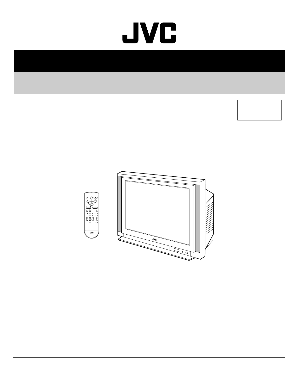
COLOUR TELEVISION
AV-34LX
BASIC CHASSIS
CH
POWER
DISPLAY
MENU
CHANNEL VOLUME
SYSTEM
COLOUR
SOUND MUTING
TV/VIDEO
123
456
PICTURE MODE
7809
CHANNEL SCAN
RETURN
-/--
OFF TIMER
ECO SENSOR
RM-C356 REMOTE CONTROL UNIT
RM-C357-1C
AV-34LX
/U
CONTENTS
a SPECIFICATIONS ....................................................................................................................................2
a SAFETY PRECAUTIONS ........................................................................................................................3
a FEATURES ..............................................................................................................................................4
a FUNCTIONS .............................................................................................................................................5
a SPECIFIC SERVICE INSTRUCTIONS ....................................................................................................6
a SERVICE ADJUSTMENTS ....................................................................................................................14
a PARTS LIST ...........................................................................................................................................37
¤ OPERATING INSTRUCTIONS (APPENDIX)
¤ STANDARD CIRCUIT DIAGRAM (APPENDIX) .................................................................................. 2-1
COPYRIGHT © 2002 VICTOR COMPANY OF JAPAN, LTD.
No. 51992
Mar. 2002
Page 2
AV-34LX
SPECIFICATIONS
Items
Dimensions (W × H × D)
Mass 65.8kg
TV RF System B, G, I, D, K, M
Colour System TV Mode PAL / SECAM / NTSC3.58 / NTSC4.43
VIDEO Mode PAL / SECAM / NTSC3.58 / NTSC4.43
Stereo System Playback Only
Receiving Frequency VHF (VL) 46.25MHz – 140.25MHz (AU0 – S6)
VHF (VH) 147.25MHz – 423.25MHz (S7 – S36)
UHF 431.25MHz – 863.25MHz (S37 – CHINA 57)
CATV ● Cable TVs of Mid (X-Z, S1-S10)
Intermediate VIF Carrier 38.0MHz
Frequency 31.5MHz (6.5MHz)
SIF Carrier 32.0MHz (6.0MHz)
Colour Sub Carrier Frequency PAL (4.43MHz), SECAM (4.40625MHz / 4.25MHz)
Aerial Input Terminal 75Ø Unbalanced
Power Input AC110 – 240V, 50 / 60Hz
Power Consumption 180W
Picture Tube Visible size : 80cm measured diagonally
High Voltage 32kV +1/–1.5kV (at cut-off in service mode)
Speaker 5 × 12cm Oval type ×2
Audio Output 7W ×2
Video / Audio Input (1 / 2 / 3) Video(1,3) : 1Vp-p, 75Ø (RCA pin jack)
89.8cm × 72.8cm × 57.9cm
Super (S11-S20) & Hyper (S21-S41) bands receivable
32.5MHz (5.5MHz)
33.5MHz (4.5MHz)
NTSC (3.58MHz / 4.43MHz)
(Max.)
/ 110W
(Avg.)
Audio(1,2,3) : 500mVrms ( -4dBs ), High Impedance (RCA pin jack)
Component Input ( Input 2 )
Y : 1Vp-p positive (negative sync provided, when terminated with 75Ø)
CB/CR : 0.7Vp-p 75Ø
Contents
Video/Audio Output 1Vp-p, 75Ø (RCA pin jack)
500mVrms(-4dBs)
Low impedance (400Hz when modulated 100%) (RCA pin jack)
Headphone Jack Stereo mini jack (3.5φ)
Remote Control Unit RM-C357-1C
(Battery size: AA/R06/UM-3 × 2)
Design & specifications are subject to change without notice.
2 No. 51992
Page 3
SAFETY PRECAUTIONS
AC VOLTMETER
(HAVING 1000Ω/V,
OR MORE SENSITIVITY)
PLACE THIS PROBE
ON EACH EXPOSED
ME TAL PAR T
1500Ω 10W
0.15µF AC-TYPE
GOOD EARTH GROUND
1. The design of this product contains special hardware, many circuits
and components specially for safety purposes. For continued protection, no changes should be made to the original design unless
authorized in writing by the manufacturer. Replacement parts must
be identical to those used in the original circuits. Service should be
performed by qualified personnel only.
2. Alterations of the design or circuitry of the products should not be
made. Any design alterations or additions will void the manufacturer's warranty and will further relieve the manufacturer of responsibility for personal injury or property damage resulting therefrom.
3. Many electrical and mechanical parts in the products have special
safety-related characteristics. These characteristics are often not
evident from visual inspection nor can the protection afforded by
them necessarily be obtained by using replacement components
rated for higher voltage, wattage, etc. Replacement parts which have
these special safety characteristics are identified in the parts list of
Service manual. Electrical components having such features are
identified by shading on the schematics and by (!) on the parts
list in Service manual. The use of a substitute replacement which
does not have the same safety characteristics as the recommended
replacement part shown in the parts list of Service manual may
cause shock, fire, or other hazards.
4. Don't short between the LIVE side ground and ISOLATED (NEU-
TRAL) side ground or EARTH side ground when repairing.
Some model's power circuit is partly different in the GND. The difference of the GND is shown by the LIVE : ( ) side GND, the ISOLATED (NEUTRAL) : ( ) side GND and EARTH : ( ) side GND.
Don't short between the LIVE side GND and ISOLATED (NEUTRAL)
side GND or EARTH side GND and never measure the LIVE side
GND and ISOLATED (NEUTRAL) side GND or EARTH side GND
at the same time with a measuring apparatus (oscilloscope etc.).
If above note will not be kept, a fuse or any parts will be broken.
5. If any repair has been made to the chassis, it is recommended that
the B1 setting should be checked or adjusted (See ADJUSTMENT
OF B1 POWER SUPPLY).
6. The high voltage applied to the picture tube must conform with that
specified in Service manual. Excessive high voltage can cause an
increase in X-Ray emission, arcing and possible component damage, therefore operation under excessive high voltage conditions
should be kept to a minimum, or should be prevented. If severe
arcing occurs, remove the AC power immediately and determine
the cause by visual inspection (incorrect installation, cracked or
melted high voltage harness, poor soldering, etc.). To maintain the
proper minimum level of soft X-Ray emission, components in the
high voltage circuitry including the picture tube must be the exact
replacements or alternatives approved by the manufacturer of the
complete product.
AV-34LX
8. When service is required, observe the original lead dress. Extra
precaution should be given to assure correct lead dress in the high
voltage circuit area. Where a short circuit has occurred, those components that indicate evidence of overheating should be replaced.
Always use the manufacturer's replacement components.
9. Isolation Check
(Safety for Electrical Shock Hazard)
After re-assembling the product, always perform an isolation check
on the exposed metal parts of the cabinet (antenna terminals, video/
audio input and output terminals, Control knobs, metal cabinet, screw
heads, earphone jack, control shafts, etc.) to be sure the product is
safe to operate without danger of electrical shock.
(1) Dielectric Strength Test
The isolation between the AC primary circuit and all metal parts
exposed to the user, particularly any exposed metal part having a
return path to the chassis should withstand a voltage of 3000V AC
(r.m.s.) for a period of one second.
(. . . . Withstand a voltage of 1100V AC (r.m.s.) to an appliance rated
up to 120V, and 3000V AC (r.m.s.) to an appliance rated 200V or
more, for a period of one second.)
This method of test requires a test equipment not generally found in
the service trade.
(2) Leakage Current Check
Plug the AC line cord directly into the AC outlet (do not use a line
isolation transformer during this check.). Using a "Leakage Current
Tester", measure the leakage current from each exposed metal part
of the cabinet, particularly any exposed metal part having a return
path to the chassis, to a known good earth ground (water pipe, etc.).
Any leakage current must not exceed 0.5mA AC (r.m.s.).
However, in tropical area, this must not exceed 0.2mA AC (r.m.s.).
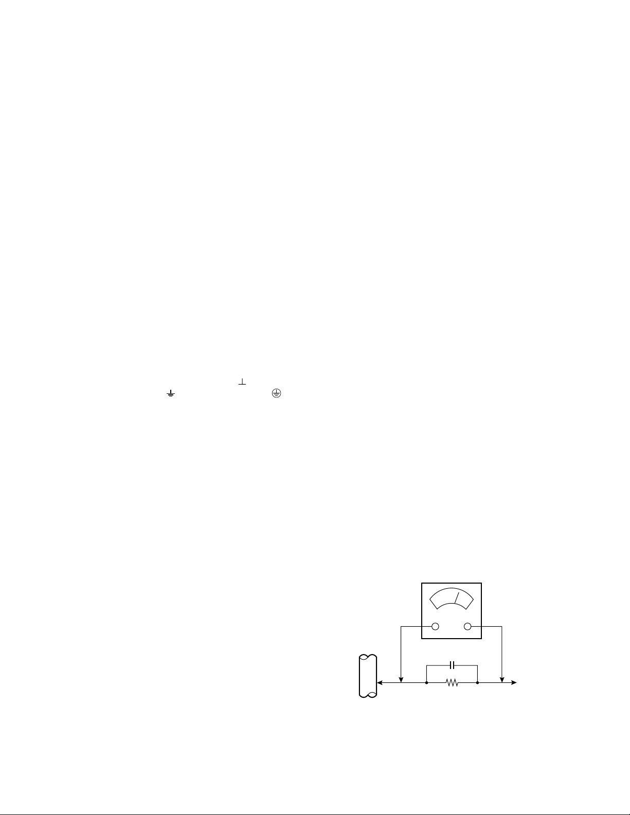
● Alternate Check Method
Plug the AC line cord directly into the AC outlet (do not use a line
isolation transformer during this check.). Use an AC voltmeter having 1000 ohms per volt or more sensitivity in the following manner.
Connect a 1500Ø 10W resistor paralleled by a 0.15µF AC-type capacitor between an exposed metal part and a known good earth
ground (water pipe, etc.). Measure the AC voltage across the resistor with the AC voltmeter. Move the resistor connection to each exposed metal part, particularly any exposed metal part having a return path to the chassis, and measure the AC voltage across the
resistor. Now, reverse the plug in the AC outlet and repeat each
measurement. Any voltage measured must not exceed 0.75V AC
(r.m.s.). This corresponds to 0.5mA AC (r.m.s.).
However, in tropical area, this must not exceed 0.3V AC (r.m.s.).
This corresponds to 0.2mA AC (r.m.s.).
7. Do not check high voltage by drawing an arc. Use a high voltage
meter or a high voltage probe with a VTVM. Discharge the picture
tube before attempting meter connection, by connecting a clip lead
to the ground frame and connecting the other end of the lead through
a 10kØ 2W resistor to the anode button.
No. 51992 3
Page 4

AV-34LX
FEATURES
s New chassis design enables use of an interactive on-screen control.
s Pure flat CRT produces fine textured picture in every detail.
s Wide range voltage (110V ~ 240V) for AC power input.
s With AUDIO/VIDEO/COMPONENT input terminals.
s I 2 C bus control utilizes single chip ICs.
s By means of AUTO PROGRAM, the TV stations can be selected
automatically and the TV channels can also be rearranged automatically.
s Built-in DIGITAL ECO MODE (ECONOMY, ECOLOGY).
In accordance with the brightness in a room, the brightness and/or
contrast of the picture can be adjusted automatically to make the
optimum picture which is easy on the eye.
s Built-in OFF TIMER & RETURN +.
4 No. 51992
Page 5
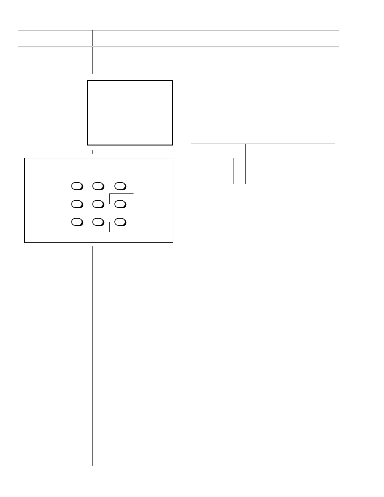
FUNCTIONS
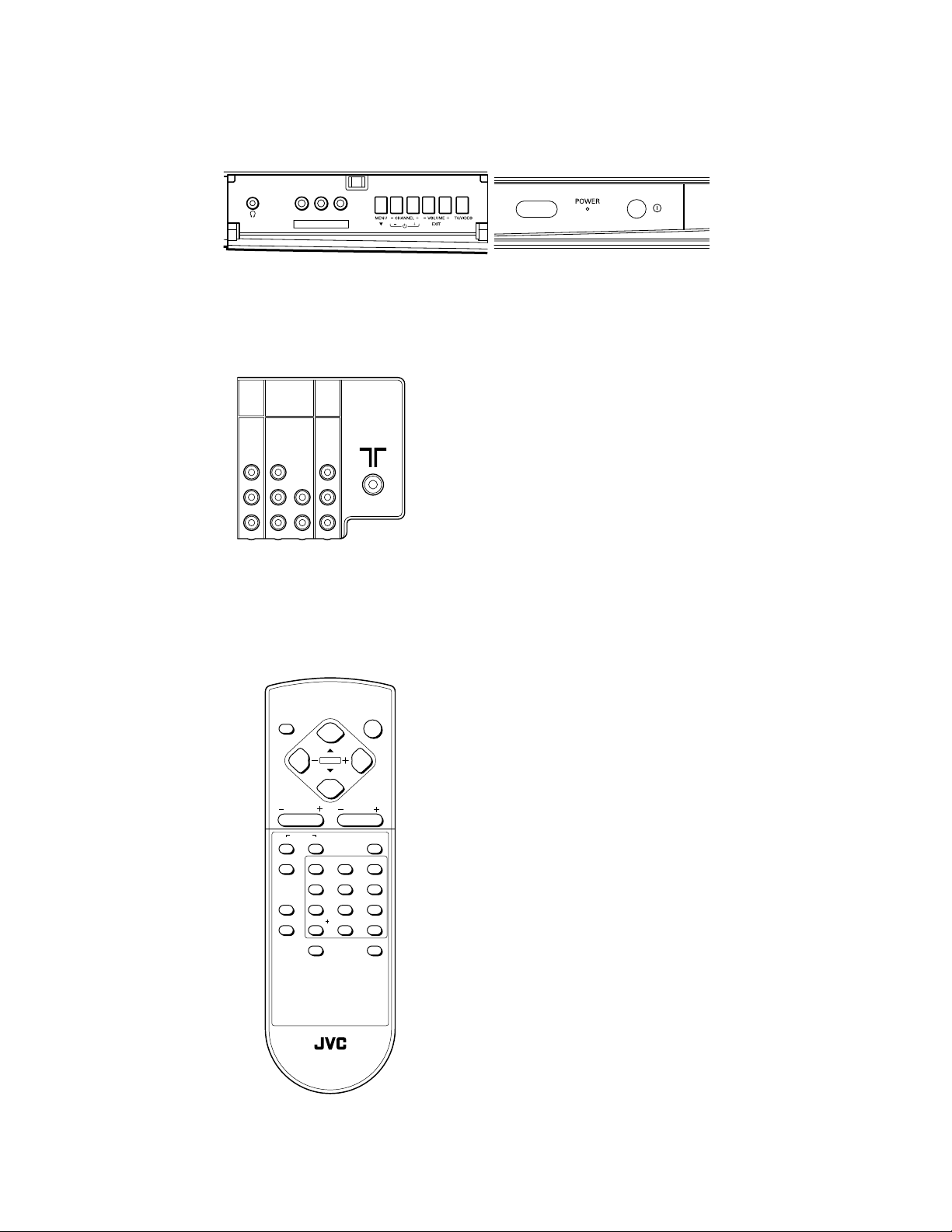
a FRONT PANEL
L/MONOVR
IN (VIDEO-3)
a REAR PANEL
COMPONENT
VIDEO-1
(
)
VIDEO-2
INPUT
INPUT
AV-34LX
OUTPUT
V
Y
/
V
C
B
L
/
MONO
R
R
a REMOTE CONTROL UNIT
DISPLAY
CHANNEL VOLUME
COLOUR
TV/VIDEO
PICTURE MODE
CHANNEL SCAN
V
L
L
/
MONO
RRC
RM-C357-1C
MENU
SYSTEM
SOUND MUTING
123
456
7809
RETURN
ECO SENSOR
POWER
-/--
OFF TIMER
RM-C357 REMOTE CONTROL UNIT
No. 51992 5
Page 6

AV-34LX
SPECIFIC SERVICE INSTRUCTIONS
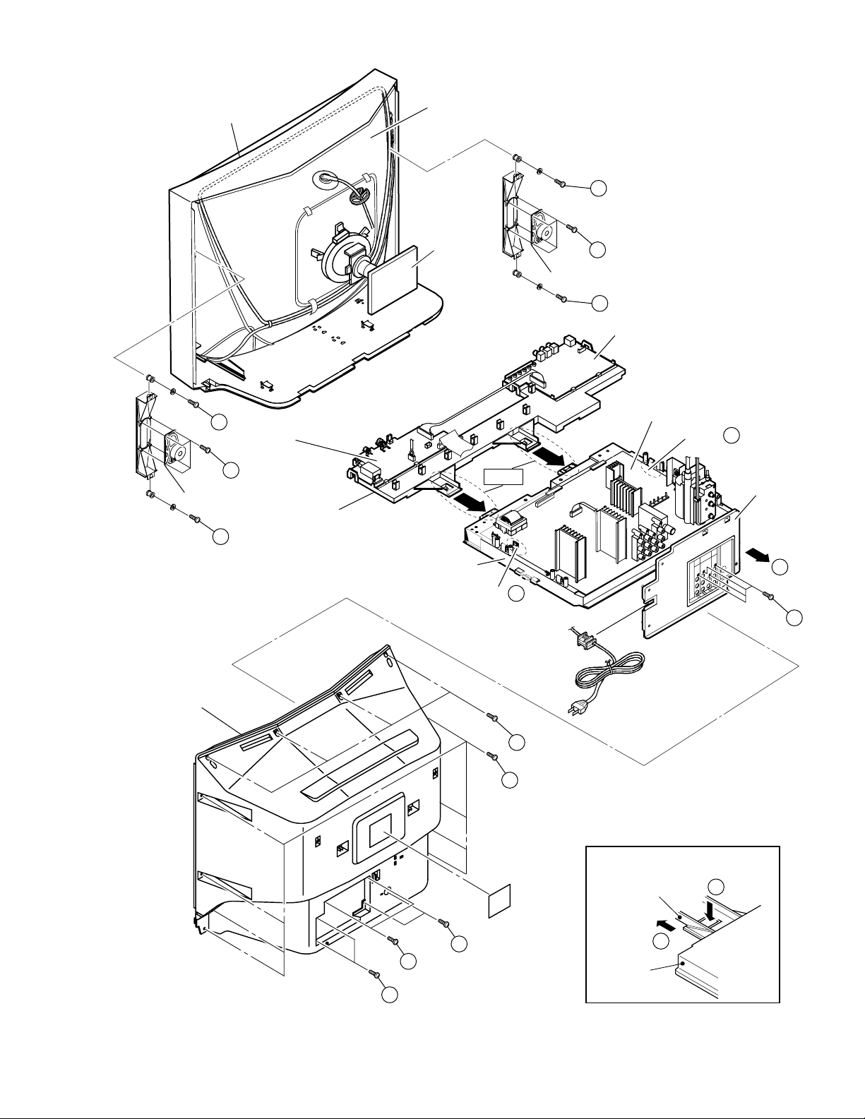
DISASSEMBLY PROCEDURE
REMOVING THE REAR COVER
1. Unplug the AC power cord.
2. Remove the 18 screws marked
3. Withdraw the Rear cover toward you.
[CAUTION]
When reinstalling the rear cover, carefully push it inward after in-
•
serting the Main PWB into the rear cover groove.
as shown in Fig.1.
Å
REMOVING THE CHASSIS (CHASSIS BASE AND
CONTROL BASE)
After removing the rear cover.
•
1. Slightly raise the both sides of the chassis by hand and remove the
2 claws marked ı under the chassis from the front cabinet as shown
in Fig.1.
2. Withdraw the chassis backward.
(If necessary, take off the wire clamp, connector’s etc.)
When conducting a check with power supplied, be sure to confirm
*
that the CRT earth wire is connected to the CRT SOCKET PWB
and the Main PWB.
CHECKING THE MAIN PW BOARD
1. To check the back side of the Main PWB.
1) Pull out the chassis. (Refer to REMOVING THE CHASSIS).
2) Erect the chassis vertically so that you can easily check the back
side of the Main PWB.
[CAUTION]
When erecting the chassis, be careful so that there will be no con-
•
tacting with other PW Board.
Before turning on power, make sure that the CRT earth wire and
•
other connectors are properly connected.
When repairing, connect the Deg. coil to the DEG. connector on the
•
Main PWB.
WIRE CLAMPING AND CABLE TYING
1. Be sure to clamp the wire.
2. Never remove the cable tie used for tying the wires together.
Should it be inadvertently removed, be sure to tie the wires with a
new cable tie.
REMOVING THE AV TERMINAL BOARD
After removing the rear cover.
•
1. Remove the 4 screws marked Ç as shown in Fig.1.
2. When you pull out the AV Terminal board in the direction of arrow
marked Î as shown in Fig.1, it can be removed.
REMOVING THE CONTROL BASE
After removing the rear cover and the chassis.
•
1. While pushing down the 2 claws maked ´ as shown in Fig. 2.
2. When you pull out the Control base in the direction of arrow maked
as shown in Fig. 2.
Ï
(If necessary, take off the wire, connector’s etc.)
REMOVING THE SPEAKER
After removing the rear cover.
•
1. Remove the 4 screws marked ˝ and 2 screws maked Ó as shown
in Fig.1.
2. Withdraw the speaker backward.
3. Follow the same steps when removing the other hand speaker.
6 No. 51992
Page 7
AV-34LX
FRONT CABINET
H
FRONT CONTROL
PWB (1/2)
(×4)
G
SPEAKER
H
CONTROL BASE
PICTURE TUBE
CRT
SOCKET
PWB
Fig.2
H
G
SPEAKER
(×4)
H
FRONT CONTROL PWB (2/2)
MAIN PWB
CLAW B
AV TERMINAL
BOARD
REAR COVER
A(×2)
A(×2)
CHASSIS
BASE
A(×2)
Fig.1
CLAW B
A(×8)
A(×4)
[FRONT SIDE]
CONTROL BASE
F
CHASSIS
BASE
Fig.2
D
C
(×4)
E
No. 51992 7
Page 8
AV-34LX
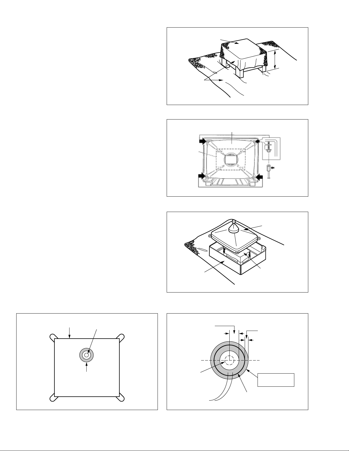
REMOVING THE CRT
* Replacement of the CRT should be performed by 2 or more persons.
After removing the rear cover, chassis etc.,
•
1. Putting the CRT change table on soft cloth, the CRT change table
should also be covered with such soft cloth (shown in Fig. 3).
2. While keeping the surface of CRT down, mount the TV set on the
CRT change table balanced will as shown in Fig. 4.
3. Remove 4 screws marked by arrows with a box type screwdriver as
shown in Fig. 4.
Since the cabinet will drop when screws have been removed, be sure
•
to support the cabinet with hands.
4. After 4 screws have been removed, put the cabinet slowly on cloth
(At this time, be carefully so as not to damage the front surface of the
cabinet) shown in Fig. 5.
The CRT should be assembled according to the opposite sequence
•
of its dismounting steps.
* The CRT change table should preferably be smaller that the CRT sur-
face, and its height be about 35cm.
CRT CHANGE TABLE
CLOTH
CRT
CHANGE
TABLE
Fig. 3
CRT
APPROX.
35cm
BOX
TYPE
SCREW
DRIVER
COATING OF SILICON GREASE FOR ELECTRICAL INSULATION ON THE CRT ANODE CAP SECTION.
Subsequent to replacement of the CRT and HV transformer or repair
•
of the anode cap, etc. by dismounting them, be sure to coat silicon
grease for electrical insulation as shown in Fig. 6.
1. Wipe around the anode button with clean and dry cloth. (Fig. 6)
2. Coat silicon grease on the section around the anode button. At this
time, take care so that any silicon greases dose not sticks to the
anode button. (Fig. 7)
夝 Silicon grease product No. KS - 650N
CRT
Anode button
CABINET
Approx.
20mm (Do not
coat grease on
this section
Fig. 4
CRT
CRT
CHANGE TABLE
Fig. 5
Silicon grease
should be coated
by 5mm or more
from the outside
diameter of anode
cap.
Silicon grease
coating
Fig. 6
8 No. 51992
Anode button
(No sticking of
silicon grease)
Coating position
of silicon grease
Anode cap
Fig. 7
Page 9
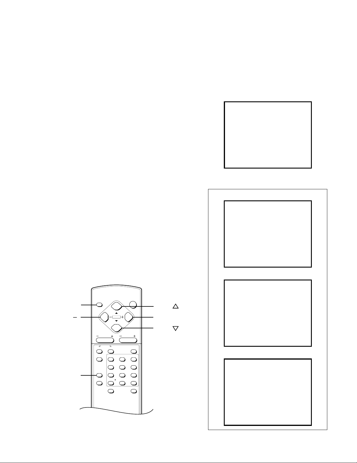
REPLACEMENT OF MEMORY IC
AV-34LX
1. MEMORY IC
This TV uses the following memory IC.
Memory IC: IC1702 on MAIN PW Board
The memory IC memorizes data for correctly operating the video
and deflection circuits. When replacing the memory IC, be sure to
use the same type IC written with the initial values of data. In other
words, use the specific IC listed in “PRINTED WIRING BOARD
PARTS LIST”. For its mounting location, refer to “ADJUSTMENT
LOCATIONS”.
2. PROCEDURE FOR REPLACING MEMORY IC
(1) Power off
Switch the power off and unplug the power cord from the wall
outlet.
(2) Replacing the memory IC
Replace the memory IC with new one. Be sure to use the memory
IC written with the initial data values.
(3) Power on
Plug the power cord into the wall outlet and switch the power on.
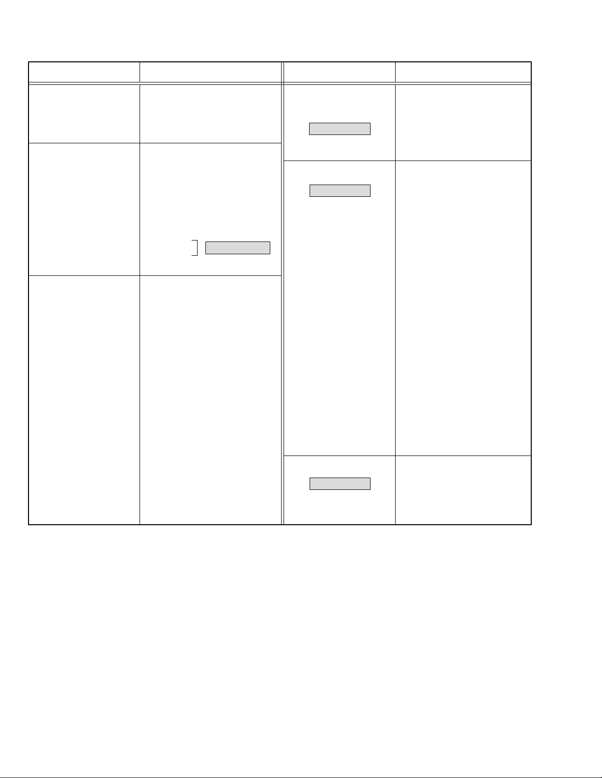
(4) Check and setting of SYSTEM CONSTANT SET:
1) Press the DISPLAY key and the PICTURE MODE key on the
remote control unit simultaneously.
The SERVICE MENU screen will be displayed.(See Fig.1.)
2) In the SERVICE MENU, press the DISPLAY key and PICTURE MODE key simultaneously. Then, the SYSTEM CONSTANT SET screen will be displayed.(See Fig.2.)
3) Check whether the setting values of the SYSTEM CONSTANT
SET are the same as those indicated in Table1.
If the value is different, select the setting item with the MENU
&/^ key, and set the correct value with the MENU –/+key.
4) Press the DISPLAY key twice to return to the normal screen.
(5) Receive channel setting
Refer to the OPERATING INSTRUCTIONS and set the receive
channels (channels preset).
(6) User setting
Check the user setting values in Table 2, and if setting value is
different, set the correct value.
For setting, refer to the OPERATING INSTRUCTIONS.
(7) Setting of SERVICE MENU
Verify the setting for each setting item in the SERVICE
MENU.(See Table 3.) If readjustment is necessary, perform adjustment referring to “SERVICE ADJUSTMENTS”.
SERVICE MENU
SERVICE MENU
1. IF
3. DEF
5. PRESET
6. PLUG & PLAY (OFF)
1-6 : SELECT DISPLAY : EXIT
2. VC
4. VSM PRESET
******* **** ***** *****
**** **** *** ***
Fig. 1
SYSTEM CONSTANT-
SYSTEM CONSTANT SET 1
SYSTEM
COMB
TILT
TEXT
SUPER BASS
LANGUAGE
-
89 : SEL
+ : OPE DISP : EXIT
Ι
MULTI
YES
YES
NO
NO
E / R / A / F
NAME OF REMOTE CONTROL KEYS
DISPLAY
MENU
PICTURE
MODE
DISPLAY
MENU
CHANNEL VOLUME
SYSTEM
COLOUR
SOUND MUTING
TV/VIDEO
PICTURE MODE
CHANNEL SCAN
123
456
7809
RETURN
ECO SENSOR
POWER
OFF TIMER
SYSTEM CONSTANT-
SYSTEM CONSTANT SET 2
MSP
MENU
MENU
MENU
+
BILINGUAL
B / B SOUND
TUNER
COLOUR AUTO
89 : SEL
-
+ : OPE DISP : EXIT
SYSTEM CONSTANT-
SYSTEM CONSTANT SET 3
-/--
LOCK 1 MHz
156.25 kHz
31.25 kHz
89 : SEL
500 kHz
250 kHz
-
+ : OPE DISP : EXIT
ΙΙ
NO
NO
NO
MU
NO
ΙΙΙ
020
020
020
015
015
Fig. 2
No. 51992 9
Page 10
AV-34LX
SETTING OF SYSTEM CONSTANT SET
Setting item Setting content Setting value
SYSTEM
COMB
TILT
TEXT
SUPER BASS
LANGUAGE
MSP
BILINGUAL
B/B SOUND
TUNER
COLOUR AUTO
LOCK 1MHz
MULTI TRIPLE
YES NO
YES NO
YES NO
YES NO
E/R/C E/R/A/F
E/F E/A
E/R E/C E/A/F
YES NO
YES NO
YES NO
MU MA
YES NO
000 024
MULTI
YES
YES
NO
NO
E/R/A/F
NO
NO
NO
MU
NO
020
500KHz
250KHz
156.25KHz
31.25KHz
000 024
000 024
000 024
000 024
Table 1
020
020
015
015
10 No. 51992
Page 11
USER SETTING VALUES
Setting item Setting value
SUB POWER ON
CHANNEL POSITION 1 POSITION
CHANNEL PRESET REFER TO OPERATING INSTRUCTIONS
VOLUME 15 ± 2
TV/VIDEO TV
VNR OFF
COMPRESS (16:9) OFF
AUTO SHUTOFF OFF
CHILD LOCK OFF
BLUE BACK ON
VIDEO-2 SET VIDEO
LANGUAGE ENG
MONO SURROUND OFF
AI VOLUME ON
ON SCREEN DISPLAY POSITION INDICATION
COLOUR SYSTEM PAL
SOUND SYSTEM B/G
PICTURE MODE-VSM BRIGHT
OFF TIMER 00
ECO SENSOR OFF
PICTURE TILT 00
BASS CENTRE
TREBLE CENTRE
BALANCE CENTRE
AV-34LX
Table 2
No. 51992 11
Page 12
AV-34LX
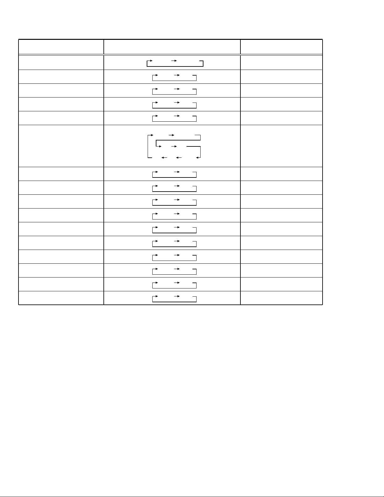
SERVICE MENU SETTING ITEMS
Service menu Setting item
1. IF 1. VCO
2. DELAY POINT
2. VC 1. CUTOFF(R/G)
2. DRIVE(R/G/B)
3. BRIGHT
4. CONT
5. COLOUR
6. TINT
7. SHARP
8. YDELAY
3. DEF 1. VER. SLOPE
2. VER. HEIGHT
3. VER. POSITION
4. VER. SCURVE
5. HOR. POSITION
6. HOR. WIDTH
7. EW-PIN
8. EW-TRAPEZ
9. UP CORNER
10. DW CORNER
11. HOR. PARALL
12. HOR. BOW
13. V. ZOOM
Do not adjust
Service menu Setting item
4. VSM PRESET 1. TINT
(BRIGHT/STD/SOFT) 2. COLOUR
Do not adjust
5. PRESET 1. CB
Do not adjust
6.
PLUG & PLAY(OFF)
3. BRIGHT
4. CONT
5. SHARP
2. ACL
3. MUS
4. MAT
5. FCO
6. BPS
7. IFLH
8. VID
9. STM
10. AFCW
11. VSW
12. FFI
13. AGC
14. CL
15. AKB
16. HBL
17. BKS
18. READ STATUS
19. VNR
Table 3
12 No. 51992
Do not adjust
Page 13

REPLACEMENT OF CHIP COMPONENT
CAUTIONS
a
1. Avoid heating for more than 3 seconds.
2. Do not rub the electrodes and the resist parts of the pattern.
3. When removing a chip part, melt the solder adequately.
4. Do not reuse a chip part after removing it.
SOLDERING IRON
a
1. Use a high insulation soldering iron with a thin pointed end of it.
2. A 30w soldering iron is recommended for easily removing parts.
REPLACEMENT STEPS
a
1. How to remove Chip parts
Resistors, capacitors, etc.
(1) As shown in the figure, push the part with tweezers and alter-
nately melt the solder at each end.
AV-34LX
2. How to install Chip parts
Resistors, capacitors, etc.
(1) Apply solder to the pattern as indicated in the figure.
(2) Shift with tweezers and remove the chip part.
Transistors, diodes, variable resistors, etc.
(1) Apply extra solder to each lead.
SOLDER
(2) As shown in the figure, push the part with tweezers and alter-
nately melt the solder at each lead. Shift and remove the chip
part.
SOLDER
(2) Grasp the chip part with tweezers and place it on the solder.
Then heat and melt the solder at both ends of the chip part.
Transistors, diodes, variable resistors, etc.
(1) Apply solder to the pattern as indicated in the figure.
(2) Grasp the chip part with tweezers and place it on the solder.
(3) First solder lead A as indicated in the figure.
A
B
C
(4) Then solder leads B and C.
A
Note : After removing the part, remove remaining solder from the
pattern.
No. 51992 13
B
C
Page 14

AV-34LX
SERVICE ADJUSTMENTS
ADJUSTMENT PREPARATION:
1. You can make the necessary adjustments for this unit with either the remote control unit or with the adjustment equipment and parts
as given below.
2. Adjustment with the remote control unit is made on the basis of the initial setting values, however, the new setting values which set the
screen to its optimum condition may differ from the initial settings.
3. Make sure that AC power is turned on correctly.
4. Turn on the power for the set and test equipment before use, and start the adjustment procedures after waiting at least 30 minutes.
5. Unless otherwise specified, prepare the most suitable reception or input signal for adjustment.
6. Never touch any adjustment parts, which are not specified in the list for this adjustment-variable resistors, transformers, capacitors, etc.
7. Presetting before adjustment.
Unless otherwise specified in the adjustment instructions, preset the following functions with the remote control unit.
User mode setting position
•
Setting item Setting value
PICTURE MODE(VSM) BRIGHT
VNR OFF
BASS,TREBLE,BALANCE CENTRE
TINT,COLOUR,BRIGHT,CONT,SHARP CENTRE
MEASURING INSTRUMENT
1. DC voltmeter (or Digital voltmeter)
2. Oscilloscope
3. Signal generator (Pattern generator) [PAL/SECAM/NTSC]
4. Remote control unit
ADJUSTMENT ITEMS
B1 POWER SUPPLY
•
FOCUS ADJUSTMENT
•
IF CIRCUIT ADJUSTMENTS
•
Adjustment of VCO (CW)
Adjustment of DELAY POINT (AGC TAKE-OVER)
VC (VIDEO/CHROMA) CIRCUIT ADJUSTMENTS
•
Adjustment of WHITE BALANCE (Low light)
Adjustment of WHITE BALANCE (High light)
Adjustment of SUB BRIGHT
Adjustment of SUB CONTRAST
Adjustment of SUB COLOR-Ι
Adjustment of SUB COLOR-ΙΙ
Adjustment of SUB TINT-Ι
Adjustment of SUB TINT-ΙΙ
DEFLECTION CIRCUIT ADJUSTMENTS
•
Adjustment of V. SLOPE
Adjustment of V. POSITION
Adjustment of V. HEIGHT
Adjustment of H. POSITION
Adjustment of H. WIDTH
Adjustment of SIDE PIN
Adjustment of TRAPEZIUM
Adjustment of V. S-CURVE
Adjustment of CORNER
Adjustment of H. PARALLEL
Adjustment of H. BOW
VSM PRESET SETTING
•
PRESET SETTING
•
PURITY ADJUSTMENT
•
CONVERGENCE ADJUSTMENTS
•
STATIC CONVERGENCE adjustment
DYNAMIC CONVERGENCE adjustment
14 No. 51992
Page 15

ADJUSTMENT LOCATIONS
AV-34LX
FRONT CONTROL PWB(1/2) FRONT CONTROL PWB(2/2)
POWER
SW.
S901
PW
FRONT
CN002
R
W
CN001
S804
S805
S806 S802
CN002
CN00A
S803S801
J304 J303 J302
MAIN PWB
Z
W
DEG
CN001
T
18
IC702
IC701
J801
CN003
FRONT
FRONT
S801 : CH UP +
S802 : CH DOWN –
S803 : MENU
S804 : TV/VIDEO
S805 : VOL UP+
S806 : VOL DOWN –
J804J801 J802 J803
AV IN/OUT
CRT SOCKET PWB
TP-47G
TU001
GND B1
5
S
61
U
TP-47B
TP-E
HV
16
1
HVT
UPPER : FOCUS (F1)
MIDDLE : FOCUS (F2)
LOWER : SCREEN
(SOLDER SIDE)
TOP
E1
81
T
16
CRT EARTH
(BRAIDED ASS'Y)
U
No. 51992 15
Page 16

AV-34LX
BASIC OPERATION IN SERVICE MENU
1. TOOL OF SERVICE MENU OPERATION
Operate the SERVICE MENU with the remote control unit.
2. SERVICE MENU ITEMS
With the SERVICE MENU, various settings (adjustments) can be made, and they are broadly classified in the following items of settings:
1.IF ......................................For entering/adjusting the setting values (adjustment values) of the IF circuit.
•
2.VC ....................................For entering/adjusting the setting values (adjustment values) of the VIDEO/CHROMA circuit.
•
3.DEF ..................................For entering/adjusting the setting values (adjustment values) of the DEFLECTION circuit.
•
4.VSM PRESET ..................For setting the values of STANDARD, SOFT and BRIGHT.
•
5.PRESET ........................... For setting the values of the preset.
•
6.PLUG & PLAY (OFF). ...... This is not used for service.
•
3. BASIC OPERATION IN SERVICE MENU
(1) How to enter SERVICE MENU
Press the DISPLAY key and the PICTURE MODE key on the remote control unit simultaneously.
The SERVICE MENU screen will be displayed. (See Fig. 1 on the next page.)
(2) Selection of SUB MENU SCREEN
Press one of the keys 1 to 6 on the remote control unit, and select the SUB MENU SCREEN from the SERVICE MENU. (See Fig.1 on the
next page.)
(VSM:video status memory)
SERVICE MENU → SUB MENU 1. IF
2. VC
3. DEF
4. VSM PRESET
5. PRESET
6. PLUG & PLAY (OFF)
(3) Method of Setting
*Once the setting values are set, they are memorized automatically.
*It must not adjust without inputting a signal.
1) 1. IF
[1.VCO ]
(a) 1 Key......................... Select 1.IF.
(b) 1 Key......................... Select 1.VCO.
(c) DISPLAY Key ............ When this pressed twice, you will return to the SERVICE MENU.
Under normal conditions, no adjustment is required.
[2.DELAY POINT ]
(a) 1 Key......................... Select 1. IF.
(b) 2 Key......................... Select 2.DELAY POINT.
(c) MENU –/+Key ........... Adjust the setting value.
(d) DISPLAY Key ........... When this is pressed twice, you will return to the SERVICE MENU.
2) 2. VC, 3. DEF, 4. VSM PRESET and 5. PRESET
(a) 2 ~5 Keys.................. Select one from 2. VC, 3. DEF, 4. VSM PRESET and 5. PRESET.
(b) MENU &/^ key ....... Select setting items.
(c) MENU –/+Key ........... Adjust the setting values of the setting items.
(d) DISPLAY Key ........... When this is pressed, you will return to the SERVICE MENU.
•
Use the number keys on the remote control unit for setting of WHITE BALANCE.
•
For the setting, refer to each item concerned.
3) 6. PLUG & PLAY (OFF)
This is not used for service.
(4) Release of SERVICE MENU
After completing the setting, return to the SERVICE MENU by pressing the DISPLAY key, then again press the DISPLAY key to return to the
normal screen.
16 No. 51992
Page 17

AV-34LX
SERVICE MENU
SERVICE MENU
1. IF
3. DEF
5. PRESET
6. PLUG & PLAY (OFF)
1-6 : SELECT DISPLAY : EXIT
******* **** ***** *****
**** **** *** ***
2. VC
4. VSM PRESET
SUB MENU 1. IF
IF
1. VCO
2. DELAY POINT
1-2 : SELECT DISPLAY : EXIT
SUB MENU 2. VC
V/C
1. CUTOFF
50 Hz
MENU 89: SELECT
MENU
-
/+ : OPERATE
(R)
(G)
DISPLAY : EXIT
PAL
**
**
Setting item
1. CUTOFF (R/G)
2. DRIVE (R/G/B)
3. BRIGHT
4. CONT
5. COLOUR
6. TINT
7. SHARP
8. YDELAY
VCO (CW)
TOO HIGH
ABOVE REFERENCE
BELOW REFERENCE
TOO LOW
DELAY POINT VHF
AGC TAKE-OVER
-
/+ : OPERATE
MHz
*****
DISPLAY : EXIT
**
DISPLAY : EXIT
SUB MENU 3. DEF
DEF 4 : 3
1. VER. SLOPE
50Hz
MENU 89: SELECT
MENU
-
/+ : OPERATE
PAL
**
DISPLAY : EXIT
SUB MENU 4. VSM PRESET
BRIGHT
TINT
COLOUR
BRIGHT
CONT
SHARP
MENU 89: SELECT
MENU
-
/+ : OPERATE
**
**
**
**
**
DISPLAY : EXIT
SUB MENU 5. PRESET
PRESET 50Hz B/G
1. CB
MENU 89: SELECT
MENU
-
/+ : OPERATE
PAL
*
DISPLAY : EXIT
4 : 3 / 16 : 9, 50Hz / 60Hz
1. VER. SLOPE
2. VER. HEIGHT
3. VER. POSITION
4. VER. SCURVE
5. HOR. POSITION
6. HOR. WIDTH
BRIGHT / STD / SOFT
Setting item
1. TINT
2. COLOUR
3. BRIGHT
4. CONT
5. SHARP
1. CB
2. ACL
3. MUS
4. MAT
5. FCO
6. BPS
7. IFLH
8. VID
9. STM
Setting item
7. EW-PIN
8. EW-TRAPEZ
9. UP CORNER
10. DW CORNER
11. HOR. PARALL
12. HOR. BOW
13. V. ZOOM
Setting item
10. AFCW
11. VSW
12. FFI
13. AGC
14. CL
15. AKB
16. HBL
17. BKS
18. READ STATUS
19. VNR
Fig. 1
No. 51992 17
Page 18

AV-34LX
ADJUSTMENTS
B1 POWER SUPPLY
Item
Measuring
instrument
Test point Adjustment part Description
Check of
B1 POWER
Signal
Generator
SUPPLY
DC Voltmeter
FOCUS ADJUSTMENT
Item
Adjustment
of FOCUS
Measuring
instrument
Signal
generator
B1 (pin 1)
GND (pin 5)
[CN00S
connector
1. Receive a black and white signal.
2. Connect a DC voltmeter between B1 and GND
(between pins 1 and 5 of the connector CN00S).
3. Make sure that the voltage is DC134.5 ± 2V.
in Main PWB]
Test point Adjustment part Description
FOCUS VR1,2
[In HVT]
Notes:
• Proceed to the following this adjustment after having completed the
adjustments of B1 POWER SUPPLY, SUB BRIGHT and SUB CONT.
• Set PICTURE MODE (VSM) to “BRIGHT”.
• The final adjustment of CONVERGENCE must be done after the
FOCUS adjustment. (CONVERGENCE is changed by FOCUS adjustment.)
When makes difference by FOCUS adjustment, should be reconfirming
PURITY adjustment.
1. Receive a cross-hatch signal.
2. While looking at the screen centre, adjust the FOCUS VR2 (F2) so
that the horizontal lines will be clear and in fine detail.
3. Adjust the FOCUS VR1 (F1) so that the vertical lines will be clear
and in fine detail.
4. Make sure that the picture is in focus even when the screen gets
darkened.
IF CIRCUIT ADJUSTMENT
Item
Adjustment
of VCO (CW)
Adjustment
of DELAY
POINT
Setting
(Adjustment time)
DELAY POINT
(AGC TAKE-OVER)
Measuring
instrument
Remote
control unit
VCO (CW)
TOO HIGH
ABOVE REFERENCE
BELOW REFERENCE
TOO LOW
Remote
control unit
Test point Adjustment part Description
. MHz
DISPLAY : EXIT
NTSC 3.58 22
OTHERS 15
VCO (CW)
fv
YELLOW
DELAY POINT
(AGC TAKE-OVER)
Initial setting value
Note:
• Under normal conditions, no adjustment is required.
1. Select 1. IF from the SERVICE MENU.
2. Select 1. VCO by pressing the 1 key on the remote control unit.
3. Receive a broadcast signal.
4. Check the characters colour of the BELOW REFERENCE displayed
to yellow.
5. Press the DISPLAY key three times to return to normal screen.
1. Receive a black and white broadcast signal (colour off).
2. Select 1. IF from the SERVICE MENU.
3. Select 2. DELAY POINT by pressing the 2 key on the remote con-
trol unit.
4. Adjust the MENU –/+ key in order to eliminate any noise or beat
from the image. Any increase above the initial value produces noise
and any decrease below it produces beat.
5. Press the DISPLAY key three times to return to the normal screen.
6. Turn to other channels and make sure that there are no irregularities.
18 No. 51992
Page 19

VC (VIDEO/CHROMA) CIRCUIT ADJUSTMENT
The setting (adjustment) using the remote control unit is made on the basis of the initial setting values.
The setting values which adjust the screen to the optimum condition can be different from the initial setting values.
Do not change the initial setting values of the setting (adjustment) items not listed in “ADJUSTMENT”.
•
[SUB MENU 2. VC] : Do not adjust.
Setting (Adjustment)
item
Variable range
PAL SECAM NTSC3.58 NTSC4.43 COMPONENT
1 CUTOFF(R/G) –7 — +8 0 0/+3
2 DRIVE(R/G/B) –30 — +31 0
3 BRIGHT
(COM./TV/V-1/V-2/V-3)
–30 — +31 –1/–16/0/0/0
4 CONT –30 — +31 0 —
5 COLOUR –30 — +31 –5 –3 –12 +1 +10
6 TINT (TV/VIDEO) –30 — +31 ——–15/+6 +1/+1 —
7 SHARP (TV/VIDEO) –30 — +31 –31/–10 —/0
8
YDELAY (TV/VIDEO/S)
–8 — +7 0/+1/0 +5/+1/+1 0/+1/+1 +5/0/+1 —
Initial setting value
AV-34LX
Remark
Item
Adjustment
of WHITE
BALANCE
(Low light)
H.LINE OFF
H.LINE ON
R. CUTOFF (
Measuring
instrument
Test point Adjustment part Description
Signal
generator
Remote
control unit
MENU 89: SELECT
MENU
REMOTE CONTROL UNIT
12 3
4
8
)
56
1. CUTOFF
50 Hz
-
/+ : OPERATE
V/C
(R)
(G)
1. CUTOFF (R)
CUTOFF (G)
SCREEN VR
[In HVT]
PAL
**
**
DISPLAY : EXIT
G. CUTOFF (8)
Note:
• Set PICTURE MODE (VSM) to “BRIGHT”.
1. Receive a PAL black and white signal (colour off).
2. Select 2. VC from the SERVICE MENU.
3. Select 1. CUTOFF (R) and (G) with MENU &/^ key, and set each
value to initial setting value with the 4 and 7 keys, or 5 and 8 keys on
the remote control unit.
4. Press the 1 key on the remote control unit to produce a single hori-
zontal line.
5. Turn the SCREEN VR fully counterclockwise, then slowly turn it clockwise to where a red, blue or green colour is faintly visible.
6. Use the keys 4 and 7 or 5 and 8 on the remote control unit and
adjust the other 2 colours to where the single horizontal line appears white.
7. Turn the SCREEN VR to where the single horizontal line glows faintly.
8. Press the 2 key to return to 1. CUTOFF screen.
9. Press the DISPLAY key twice to return to the normal screen.
Setting (Adjustment) Variable Initial setting
Item range value
1. CUT OFF
R –7 — +8 0
G –7 — +8 +3
R. CUTOFF (
789
)
9
G.CUTOFF (
)
9
No. 51992 19
Page 20
AV-34LX
Item
Adjustment
of WHITE
BALANCE
(High light)
R. DRIVE (
R. DRIVE (
Measuring
instrument
Signal
generator
Test point Adjustment part Description
2. DRIVE (R)
DRIVE (G)
DRIVE (B)
Remote
control
unit
V/C
1. DRIVE
50 Hz
MENU 89: SELECT
MENU
(R)
(G)
(B)
-
/+ : OPERATE
PAL
**
**
**
DISPLAY : EXIT
REMOTE CONTROL UNIT
12 3
4
8
) B. DRIVE (8)
789
)
9
56
G. DRIVE (8)
B. DRIVE (
G.DRIVE (
Notes:
• Proceed to the following this adjustment after having completed the
adjustment of LOW LIGHT WHITE BALANCE.
• Set PICTURE MODE (VSM) to “BRIGHT”.
1. Receive a PAL black and white signal (colour off).
2. Select 2. VC from the SERVICE MENU.
3. Select 2. DRIVE (R), (G) and (B) with MENU &/^ key, and set
each value to initial setting value with the 4 to 9 keys on the remote
control unit.
4. Use the keys 4 to 9 to produce a white screen.
5. Press the DISPLAY key twice to return to the normal screen.
Setting (Adjustment) Variable Initial setting
Item range value
R –30 — +31 0
2. DRIVE G –30 — +31 0
B –30 — +31 0
)
9
)
9
Adjustment
of
SUB BRIGHT
Adjustment
of
SUB CONTRAST
Remote
control unit
Remote
control unit
3. BRIGHT
4. CONT
Notes:
• Proceed to the following this adjustment after having completed the
adjustments of LOW LIGHT WHITE BALANCE and HIGH LIGHT
WHITE BALANCE.
• Set PICTURE MODE (VSM) to “BRIGHT”.
1. Receive a broadcast.
2. Select 2. VC from the SERVICE MENU.
3. Select 3. BRIGHT with the MENU &/^ key.
4. Set the initial setting value with the MENU –/+ key.
5. If the brightness is not best with the initial setting value, make fine
adjustment until you get the best brightness.
6. Press the DISPLAY key twice to return to the normal screen.
Notes:
• Proceed to the following this adjustment after having completed the
adjustment of SUB BRIGHT.
• Set PICTURE MODE (VSM) to “BRIGHT”.
1. Receive a broadcast.
2. Select 2. VC from the SERVICE MENU.
3. Select 4. CONT with the MENU &/^ key.
4. Set the initial setting value with the MENU –/+ key.
5. If the contrast is not best with the initial setting value, make fine
adjustment until you get the best contrast.
6. Press the DISPLAY key twice to return to the normal screen.
20 No. 51992
Page 21

AV-34LX
Item
Adjustment
of
SUB
COLOUR-I
Measuring
instrument
Remote
control unit
Test point Adjustment part Description
5. COLOUR
[Method of adjustment without measuring instrument]
Notes:
• Proceed to the following this adjustment after having completed the
adjustment of SUB CONT.
• Set PICTURE MODE (VSM) to “BRIGHT”.
– PAL COLOUR –
1. Receive a PAL broadcast.
2. Select 2. VC from the SERVICE MENU.
3. Select 5. COLOUR with the MENU &/^ key.
4. Set the initial setting value for PAL COLOUR with the MENU –/+ key.
5. If the colour is not best with the initial setting value, make fine ad-
justment until you get the best colour.
6. Press the DISPLAY key twice to return to the normal screen.
– SECAM COLOUR –
7. Receive a SECAM broadcast.
8. Press the COLOUR SYSTEM button on the remote control unit to
select the SECAM colour system.
9. Make fine adjustment of SECAM COLOUR in the same way as for
“PAL COLOUR”.
– NTSC 3.58 COLOUR –
10. Receive a NTSC 3.58MHz broadcast.
11. Press the COLOUR SYSTEM button on the remote control unit to
select the NTSC 3.58 colour system.
12. Make similar fine adjustment of NTSC 3.58 COLOUR in the same
way as for “PAL COLOUR”.
– NTSC 4.43 COLOUR –
When adjustment is done for NTSC 3.58 COLOUR, appropriate
values are automatically set for NTSC 4.43 COLOUR.
Adjustment
of
SUB
COLOUR-II
Signal
generator
Oscilloscope
Remote
control unit
Cy
Y
W
TP-47G
TP-E (H)
[CRT
SOCKET
PWB]
Mg
G
5. COLOUR [Method of adjustment using measuring instrument]
Notes:
• Proceed to the following this adjustment after having completed the
adjustment of SUB CONT.
• Set PICTURE MODE (VSM) to “BRIGHT”.
– PAL COLOUR –
1. Receive a PAL colour bar signal (full field colour bar 75% white).
2. Select 2. VC from the SERVICE MENU.
3. Select 5. COLOUR with the MENU &/^ key.
4. Set the initial setting value of PAL COLOUR with the MENU –/+ key.
5. Connect the oscilloscope between TP-47G and TP-E.
B
R
(A)
(–)
0V
(+)
6.
Adjust PAL COLOUR to set the value (A) in the figure to +8V (V
W-G
– SECAM COLOUR –
7. Receive a SECAM colour bar signal (full field colour bar 75% white).
8. Press the COLOUR SYSTEM button on the remote control unit to
select the SECAM colour system.
9. Set the initial setting value of SECAM COLOUR with the MENU –/+ key.
).
10. Adjust SECAM COLOUR to set the value (A) in the figure to +2V
(VW-G ).
– NTSC 3.58 COLOUR –
11. Receive a NTSC 3.58 colour bar signal (full field colour bar 75% white).
12. Press the COLOUR SYSTEM button on the remote control unit to
select the NTSC 3.58 colour system.
13. Set the initial setting value of NTSC 3.58 COLOUR with the MENU
–/+ key.
14. Adjust NTSC 3.58 COLOUR to set the value (A) in the figure to
+2V (VW-G).
– NTSC 4.43 COLOUR –
When adjustment is done for NTSC 3.58 COLOUR, appropriate
values are automatically set for NTSC 4.43 COLOUR.
No. 51992 21
Page 22
AV-34LX
Item
Adjustment
of
SUB TINT-I
Measuring
instrument
Remote
control unit
Test point Adjustment part Description
6. TINT [Method of adjustment without measuring instrument]
Notes:
• Proceed to the following this adjustment after having completed the
adjustment of SUB CONT.
• Set PICTURE MODE (VSM) to “BRIGHT”.
– NTSC 3.58 TINT –
1. Receive a NTSC 3.58 colour bar signal (full field colour bar 75%
white).
2. Press the COLOUR SYSTEM button on the remote control unit to
select the NTSC 3.58 colour system.
3. Select 2. VC from the SERVICE MENU.
4. Select 6. TINT with the MENU &/^ key.
5. Set the initial setting value of NTSC 3.58 with the MENU –/+ key.
6. If you cannot get the best tint with the initial setting value, make fine
adjustment until you get the best tint.
7. Press the DISPLAY key twice to return to the normal screen.
– NTSC 4.43 TINT –
When adjustment is done for NTSC 3.58 TINT, appropriate values are
automatically set for NTSC 4.43 TINT.
Adjustment
of
SUB TINT-II
Signal
generator
Oscilloscope
Remote
control unit
(B)
W
Y
Cy
TP-47G
TP-E (H)
[CRT
SOCKET
PWB]
B
Mg
R
G
6. TINT [Method of adjustment using measuring instrument]
Notes:
• Proceed to the following this adjustment after having completed the
adjustment of SUB CONT.
• Set PICTURE MODE (VSM) to “BRIGHT”.
– NTSC 3.58 TINT –
1. Receive a NTSC 3.58 colour bar signal (full field colour bar 75%
white).
2. Press the COLOUR SYSTEM button on the remote control unit to
select the NTSC 3.58 colour system.
3. Select 2. VC from the SERVICE MENU.
4. Select 6. TINT with the MENU &/^ key.
5. Set the initial setting value of NTSC 3.58 with the MENU –/+ key.
6. Connect the oscilloscope between TP-47G and TP-E.
(–)
0V
(+)
7.
Adjust NTSC 3.58 TINT to set the value (B) in the figure to 0V (V
8. Press the DISPLAY key twice to return to the normal screen.
– NTSC 4.43 TINT –
When adjustment is done for NTSC 3.58 TINT, appropriate values are
automatically set for NTSC 4.43 TINT.
W-Cy
).
22 No. 51992
Page 23

AV-34LX
DEFLECTION CIRCUIT ADJUSTMENT
The setting (adjustment) using the remote control unit is made on the basis of the initial setting values.
The setting values which adjust the screen to the optimum condition can be different from the initial setting values.
Note:
Proceed to the following this adjustment after having completed the adjustments of SUB BRIGHT and SUB CONT.
[SUB MENU 3. DEF]
Setting
(Adjustment)
item
Variable range
COMPRESS(16:9) : OFF COMPRESS(16:9) : ON
50Hz 60Hz 50Hz 60Hz
1. VER. SLOPE -31 – +31 +3 0 —— —
2. VER. HEIGHT -31 – +31 +31 0 -29 -24 —
3. VER. POSITION -31 – +31 +2 -1 —— —
4. VER. SCURVE -31 – +31 -21 0 —— —
5. HOR. POSITION -31 – +31 +8 +7 —— +7
6. HOR. WIDTH -31 – +31 +11 -1 —— —
7. EW-PIN -31 – +31 -11 -1 -13 -12 —
8. EW-TRAPEZ -31 – +31 0 0 —— —
9. UP CORNER -31 – +31 -25 0 0 0 —
10. DW CORNER -31 – +31 -25 0 0 0 —
11. HOR. PARALL -31 – +31 0 0 —— —
12. HOR. BOW -31 – +31 0 0 —— —
13. V. ZOOM -31 – +31 -1 -1 +14 +6 —
Initial setting value
COMPONENT
DVD(50Hz/60Hz)
[COMPRESS(16:9) : OFF, fv : 50Hz mode]
Item
Adjustment
of
Measuring
instrument
Signal
generator
Test point Adjustment part Description
V. SLOPE
Remote
control unit
A
B
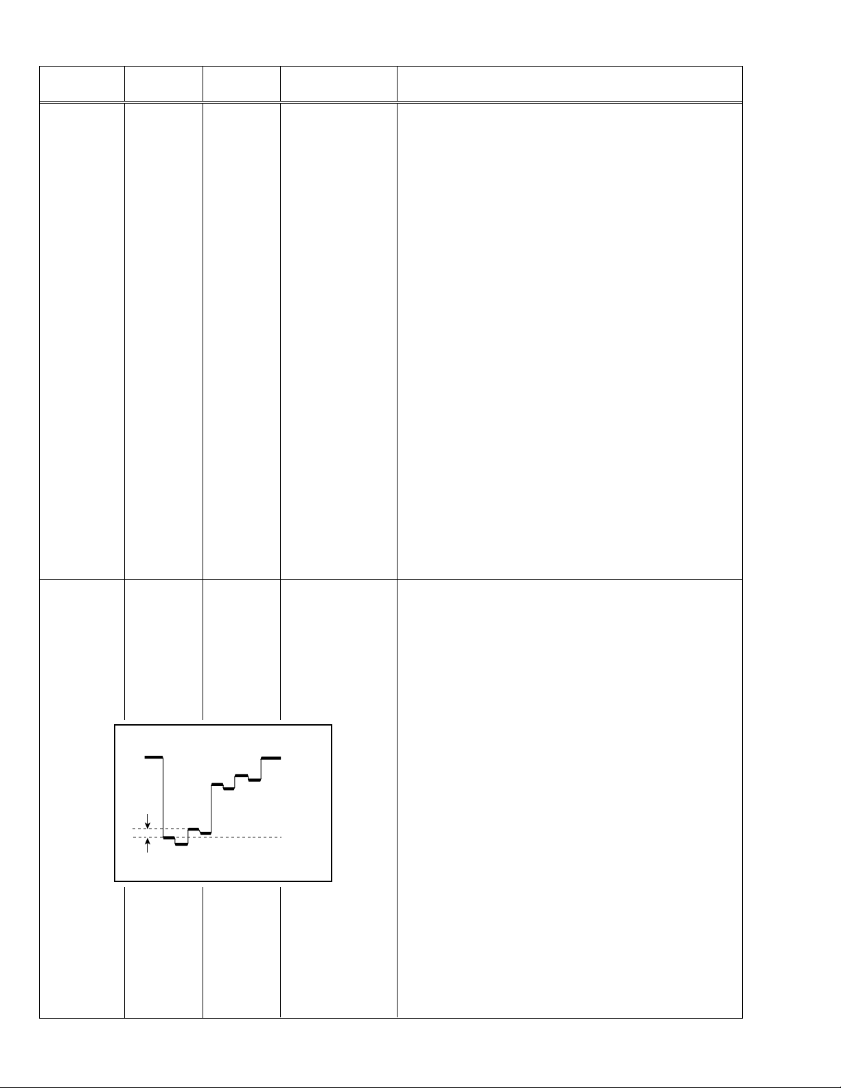
1. VER. SLOPE 1. Receive a PAL circle pattern signal of vertical frequency 50Hz.
2. Select 3. DEF from the SERVICE MENU.
3. Select 1. VER. SLOPE with the MENU &/^ key.
4. Set the initial setting value of 1. VER. SLOPE with the MENU –/+
key.
5. Adjust 1. VER. SLOPE to make “A = B” with the MENU –/+ key.
Blanking
line
(to be continued)
No. 51992 23
Page 24
AV-34LX
Item
Adjustment
of
V.POSITION
Adjustment
of
V. HEIGHT
Measuring
instrument
Signal
generator
Remote
control unit
Signal
generator
Remote
control unit
Test point Adjustment part Description
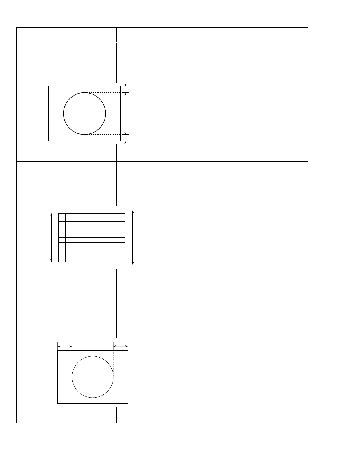
3. VER. POSITION 6. Select 3. VER. POSITION with the MENU &/^ key.
7. Set the initial setting value of 3. VER. POSITION with the MENU
–/+ key.
8. Adjust 3. VER. POSITION to make “A = B” with the MENU –/+ key.
A
B
2. VER. HEIGHT
13. V. ZOOM
9. Receive a PAL cross-hatch signal.
10. Select 2. VER. HEIGHT with the MENU &/^ key.
11. Set the initial setting value of 2. VER. HEIGHT with the MENU –/+
key.
12. Select 13. V. ZOOM with the MENU &/^ key.
13. Set the initial setting value of 13. V. ZOOM with the MENU –/+ key.
14. Adjust 13. V. ZOOM and make the vertical screen size 91% of the
picture size with the MENU –/+ key.
Screen
size
91%
Adjustment
of
H. POSITION
Picture
size
100%
Signal
5. HOR. POSITION 15. Receive a PAL circle pattern signal.
generator
Remote
control unit
CD
16. Select 5. HOR. POSITION with the MENU &/^ key.
17.
Set the initial setting value of 5. HOR. POSITION with the MENU –/+
key.
18 Adjust 5. HOR POSITION to make “C=D” with the MENU –/+ key.
(to be continued)
24 No. 51992
Page 25

AV-34LX
Item
Adjustment
of
H. WIDTH
Adjustment
of
SIDE PIN
Measuring
instrument
Signal
generator
Remote
control unit
Screen size 91%
Picture size 100%
Signal
generator
Remote
control unit
Test point Adjustment part Description
6. HOR. WIDTH 19. Receive a PAL cross-hatch signal.
20. Select 6. HOR. WIDTH with the MENU &/^ key.
21. Set the initial setting value of 6. HOR. WIDTH with the MENU –/+
key.
22. Adjust 6. HOR. WIDTH and make the horizontal screen size 91%
of the picture size with the MENU –/+ key.
7. EW-PIN 23. Select 7. EW-PIN with the MENU &/^ key.
24. Set the initial setting value of 7. EW-PIN with the MENU –/+ key.
25. Adjust 7. EW-PIN so that the first vertical lines at the left and right
edges on the screen are straight.
Adjustment
of
TRAPEZIUM
Signal
generator
Remote
control unit
Straight
8. EW-TRAPEZ 26. Select 8. EW-TRAPEZ with the MENU &/^ key.
27. Set the initial setting value of 8. EW-TRAPEZ with the MENU –/+
key.
28. Adjust 8. EW-TRAPEZ so that the vertical lines at the left and right
edges on the screen are in parallel.
Parallel
(to be continued)
No. 51992 25
Page 26

AV-34LX
Item
Adjustment
of
V.S-CURVE
Adjustment
of
CORNER
Measuring
instrument
Signal
generator
Remote
control unit
Signal
generator
Remote
control unit
Test point Adjustment part Description
4. VER. SCURVE 29. Select 4. VER. SCURVE with the MENU &/^ key.
30. Set the initial setting value of 4. VER. SCURVE with the MENU –/+
key.
31. Adjust 4. VER. SCURVE so that the spaces of each line on TOP,
CENTRE and BOTTOM become uniform.
TOP
CENTRE
BOTTOM
9. UP CORNER
10. DW CORNER
32. Select 9. UP CORNER with the MENU &/^ key.
33. Set the initial setting value of 9. UP CORNER with the MENU –/+
key.
34. Select 10. DW CORNER with the MENU &/^ key.
35. Set the initial setting value of 10. DW CORNER with the MENU –/+
key.
36. Adjust 9. UP CORNER and 10. DW CORNER so that the vertical
lines at the four corners on the screen are straight.
Adjustment
of
H. PARALL
Adjustment
of
H. BOW
Signal
generator
Remote
control unit
Signal
generator
Remote
control unit
11. HOR. PARALL 37. Select 11. HOR. PARALL with the MENU &/^ key.
38. Set the initial setting value of 11. HOR. PARALL with the MENU
–/+ key.
39. Adjust 11. HOR. PARALL to optimize the parallelogram distortion.
12. HOR. BOW 40. Select 12. HOR. BOW with the MENU &/^ key.
41. Set the initial setting value of Select 12. HOR. BOW with the MENU
–/+ key.
42. Adjust 12. HOR. BOW to optimize the horizontal arc distortion.
43. Press the DISPLAY key twice to return to the normal screen.
Straight
26 No. 51992
Page 27

[COMPRESS(16:9) : OFF, fv : 60Hz mode]
Item
Measuring
instrument
Test point Adjustment part Description
AV-34LX
Adjustment
of
V. SLOPE
Adjustment
of
V.POSITION
Signal
generator
Remote
control unit
Signal
generator
Remote
control unit
1. VER. SLOPE 1. Receive a NTSC circle pattern signal of vertical frequency 60Hz.
2. Select 3. DEF from the SERVICE MENU.
3. Select 1. VER. SLOPE with the MENU &/^ key.
4. Set the initial setting value of 1. VER. SLOPE with the MENU –/+
key.
5. Adjust 1. VER. SLOPE to make “A = B” with the MENU –/+ key.
A
Blanking
line
B
3. VER. POSITION 6. Select 3. VER. POSITION with the MENU &/^ key.
7. Set the initial setting value of 3. VER. POSITION with the MENU
–/+ key.
8. Adjust 3. VER. POSITION to make “A = B” with the MENU –/+ key.
Adjustment
of
V. HEIGHT
Screen
size
91%
Signal
generator
Remote
control unit
A
B
2. VER. HEIGHT
13. V. ZOOM
Picture
size
100%
9. Receive a NTSC cross-hatch signal.
10. Select 2. VER. HEIGHT with the MENU &/^ key.
11. Set the initial setting value of 2. VER. HEIGHT with the MENU –/+
key.
12. Select 13. V. ZOOM with the MENU &/^ key.
13. Set the initial setting value of 13. V. ZOOM with the MENU –/+ key.
14. Adjust 13. V. ZOOM and make the vertical screen size 91% of the
picture size with the MENU –/+ key.
(to be continued)
No. 51992 27
Page 28

AV-34LX
Item
Adjustment
of
H. POSITION
Adjustment
of
H. WIDTH
Measuring
instrument
Signal
Test point Adjustment part Description
5. HOR. POSITION 15. Receive a NTSC circle pattern signal.
generator
Remote
control unit
CD
Signal
6. HOR. WIDTH 19. Receive a NTSC cross-hatch signal.
generator
Remote
control unit
Screen size 91%
16. Select 5. HOR. POSITION with the MENU &/^ key.
17. Set the initial setting value of 5. HOR. POSITION with the MENU
–/+ key.
18. Adjust 5. HOR. POSITION to make “C=D” with the MENU –/+ key.
20. Select 6. HOR. WIDTH with the MENU &/^ key.
21. Set the initial setting value of 6. HOR. WIDTH with the MENU –/+
key.
22. Adjust 6. HOR. WIDTH and make the horizontal screen size 91%
of the picture size with the MENU –/+ key.
Picture size 100%
Adjustment
of
SIDE PIN
Signal
generator
7. EW-PIN 23. Select 7. EW-PIN with the MENU &/^ key.
24. Set the initial setting value of 7. EW-PIN with the MENU –/+ key.
25. Adjust 7. EW-PIN so that the first vertical lines at the left and right
Remote
control unit
Straight
(to be continued)
28 No. 51992
edges on the screen are straight.
Page 29

AV-34LX
Item
Adjustment
of
TRAPEZIUM
Adjustment
of
V.S-CURVE
Measuring
instrument
Signal
generator
Remote
control unit
Signal
generator
Remote
control unit
Test point Adjustment part Description
8. EW-TRAPEZ 26. Select 8. EW-TRAPEZ with the MENU &/^ key.
27. Set the initial setting value of 8. EW-TRAPEZ with the MENU –/+
Parallel
key.
28. Adjust 8. EW-TRAPEZ so that the vertical lines at the left and right
edges on the screen are in parallel.
4. VER. SCURVE 29. Select 4. VER. SCURVE with the MENU &/^ key.
30. Set the initial setting value of 4. VER. SCURVE with the MENU –/+
key.
31. Adjust 4. VER. SCURVE so that the spaces of each line on TOP,
CENTRE and BOTTOM become uniform.
TOP
Adjustment
of
CORNER
Adjustment
of
H. PARALL
Adjustment
of
H. BOW
Signal
generator
Remote
control unit
Signal
generator
Remote
control unit
Signal
generator
Remote
control unit
CENTRE
BOTTOM
9. UP CORNER
10. DW CORNER
32. Select 9. UP CORNER with the MENU &/^ key.
33. Set the initial setting value of 9. UP CORNER with the MENU –/+
key.
34. Sekect 10. DW CORNER with the MENU &/^ key.
35. Set the initial setting value of 10. DW CORNER with the MENU –/+
key.
36. Adjust 9. UP CORNER and 10. DW CORNER so that the vertical
lines at the four corners on the screen are straight.
11. HOR. PARALL 37. Select 11. HOR. PARALL with the MENU &/^ key.
38. Set the initial setting value of 11. HOR. PARALL with the MENU
–/+ key.
39. Adjust 11. HOR. PARALL to optimize the parallelogram distortion.
12. HOR. BOW 40. Select 12. HOR. BOW with the MENU &/^ key.
Straight
41. Set the initial setting value of Select 12. HOR. BOW with the MENU
–/+ key.
42. Adjust 12. HOR. BOW to optimize the horizontal arc distortion.
43. Press the DISPLAY key twice to return to the normal screen.
No. 51992 29
Page 30

AV-34LX
[COMPRESS(16:9) : ON, fv : 50Hz mode]
Item
Measuring
instrument
Test point Adjustment part Description
Adjustment
of
V. HEIGHT
Screen
size
Adjustment
of
SIDE PIN
Signal
generator
Remote
control unit
Signal
generator
Remote
control
unit
Screen size
13. V. ZOOM
2. VER. HEIGHT
Vertical
360mm
7. EW-PIN
1. Receive a PAL cross-hatch signal of vertical frequency 50Hz.
2. Select COMPRESS from the MENU and set COMPRESS to ON.
3. Select 3. DEF from the SERVICE MENU.
4. Set the initial setting value of 13. V. ZOOM with the MENU –/+ key.
5. Select 2. VER. HEIGHT with the MENU &/^ key.
6. Set the initial setting value of 2. VER. HEIGHT with the MENU –/+
key.
7. Adjust 2. VER. HEIGHT to set the vertical amplitude of the image to
360mm.
8. Select 7. EW-PIN with the MENU &/^ key.
9. Set the initial setting value of 7. EW-PIN with the MENU –/+ key.
10. Adjust 7. EW-PIN so tha the first vertical lines at the left and right
edges on the screen are straight.
Adjustment
of
CORNER
Signal
generator
Remote
control unit
Straight
9. UP CORNER
10. DW CORNER
11. Select 9. UP CORNER with the MENU &/^ key.
12. Set the initial setting value of 9. UP CORNER with the MENU –/+
key.
13. Select 10. DW CORNER with the MENU &/^ key.
14. Set the initial setting value of 10. DW CORNER with the MENU
–/+ key.
15. Adjust 9. UP CORNER and 10. DW CORNER so that the vertical
lines at the four corners on the screen are straight.
16. Press the DISPLAY key twice to return to the normal screen.
30 No. 51992
Page 31

[COMPRESS(16:9) : ON, fv : 60Hz mode]
Item
Measuring
instrument
Test point Adjustment part Description
AV-34LX
Adjustment
of
V. HEIGHT
Screen
Adjustment
of
SIDE PIN
size
Signal
generator
Remote
control unit
Signal
generator
Remote
control
unit
Screen size
13. V. ZOOM
2. VER. HEIGHT
Vertical
360mm
7. EW-PIN
1. Receive a NTSC cross-hatch signal of vertical frequency 60Hz.
2. Select COMPRESS from the MENU and set COMPRESS to ON.
3. Select 3. DEF from the SERVICE MENU.
4. Set the initial setting value of 13. V. ZOOM with the MENU –/+ key.
5. Select 2. VER. HEIGHT with the MENU &/^ key.
6. Set the initial setting value of 2. VER. HEIGHT with the MENU –/+
key.
7. Adjust 2. VER. HEIGHT to set the vertical amplitude of the image to
360mm.
8. Select 7. EW-PIN with the MENU &/^ key.
9. Set the initial setting value of 7. EW-PIN with the MENU –/+ key.
10. Adjust 7. EW-PIN so tha the first vertical lines at the left and right
edges on the screen are straight.
Adjustment
of
CORNER
Signal
generator
Remote
control unit
Straight
9. UP CORNER
10. DW CORNER
11. Select 9. UP CORNER with the MENU &/^ key.
12. Set the initial setting value of 9. UP CORNER with the MENU –/+
key.
13. Select 10. DW CORNER with the MENU &/^ key.
14. Set the initial setting value of 10. DW CORNER with the MENU
–/+ key.
15. Adjust 9. UP CORNER and 10. DW CORNER so that the vertical
lines at the four corners on the screen are straight.
16. Press the DISPLAY key twice to return to the normal screen.
No. 51992 31
Page 32

AV-34LX
[VIDEO-2 SET : COMPONENT, fv : 50/60Hz mode]
Item
Measuring
instrument
Test point Adjustment part Description
Adjustment
of
H. POSITION
Signal
5. HOR. POSITION 1. Receive a PAL circle pattern signal to VIDEO-2 terminal.
generator
Remote
control unit
CD
2. Select VIDEO-2 SET from the MENU and set VIDEO-2 SET to
COMPONENT.
3. Select 3. DEF from the SERVICE MENU.
4. Select 5. HOR. POSITION with the MENU &/^ key.
5.
Set the initial setting value of 5. HOR. POSITION with the MENU –/+
key.
6 Adjust 5. HOR POSITION to make “C=D” with the MENU –/+ key.
7. Press the DISPLAY key twice to return to the normal screen.
VSM PRESET SETTING
Item
Setting of
VSM
PRESET
Measuring
instrument
Remote
control unit
SUB MENU 4. VSM PRESET
BRIGHT
TINT
COLOUR
BRIGHT
CONT
SHARP
MENU 89: SELECT
MENU
-
/+ : OPERATE
Test point Adjustment part Description
1. TINT
2. COLOUR
3. BRIGHT
4. CONT
5. SHARP
1. Select 4. VSM PRESET from the SERVICE MENU.
2. Select BRIGHT with the PICTURE MODE key.
3. Adjust the MENU &/^ key and MENU –/+ key to reset the set val-
ues of 1. TINT – 5. SHARP to the values shown in the Table 5.
4. Respectively select the VSM PRESET mode for SOFT and STANDARD, and make similar adjustment as in 3 above.
5. Press the DISPLAY key twice to return to the normal screen.
[Setting Values for SUB MENU 4. VSM PRESET]
**
**
**
**
**
DISPLAY : EXIT
VSM preset
VSM mode BRIGHT STANDARD SOFT
Setting item
1. TINT
SETTING VALUE
2. COLOUR
SETTING VALUE
3. BRIGHT
SETTING VALUE
4. CONT
SETTING VALUE
5. SHARP
SETTING VALUE
15
15
15
30
15 0
15 11
32 No. 51992
Table 5
Page 33

AV-34LX
PRESET SETTING
Do not adjust 5. PRESET in the SERVICE MENU as it requires no adjustment.
•
[SUB MENU 5. PRESET]
Setting item Variable range Initial setting value
1CB 0/1 0
2ACL 0/1 0
3 MUS 0/1 0
4MAT 0/1 0
5 FCO 0/1 0
6 BPS 0/1 0
7 IFLH 0/1 0
8 VID 0/1 0
9 STM 0/1 0
10 AFCW 0/1 0
11 VSW 0/1 0
12 FFI 0/1 0
13 AGC 00/10/01 10
14 CL 50 – 95 80
15 AKB 0/1 0
16 HBL 0/1 0
17 BKS 0/1 1
18 READ STATUS ——
19 VNR 00 – 63 25
No. 51992 33
Page 34
AV-34LX
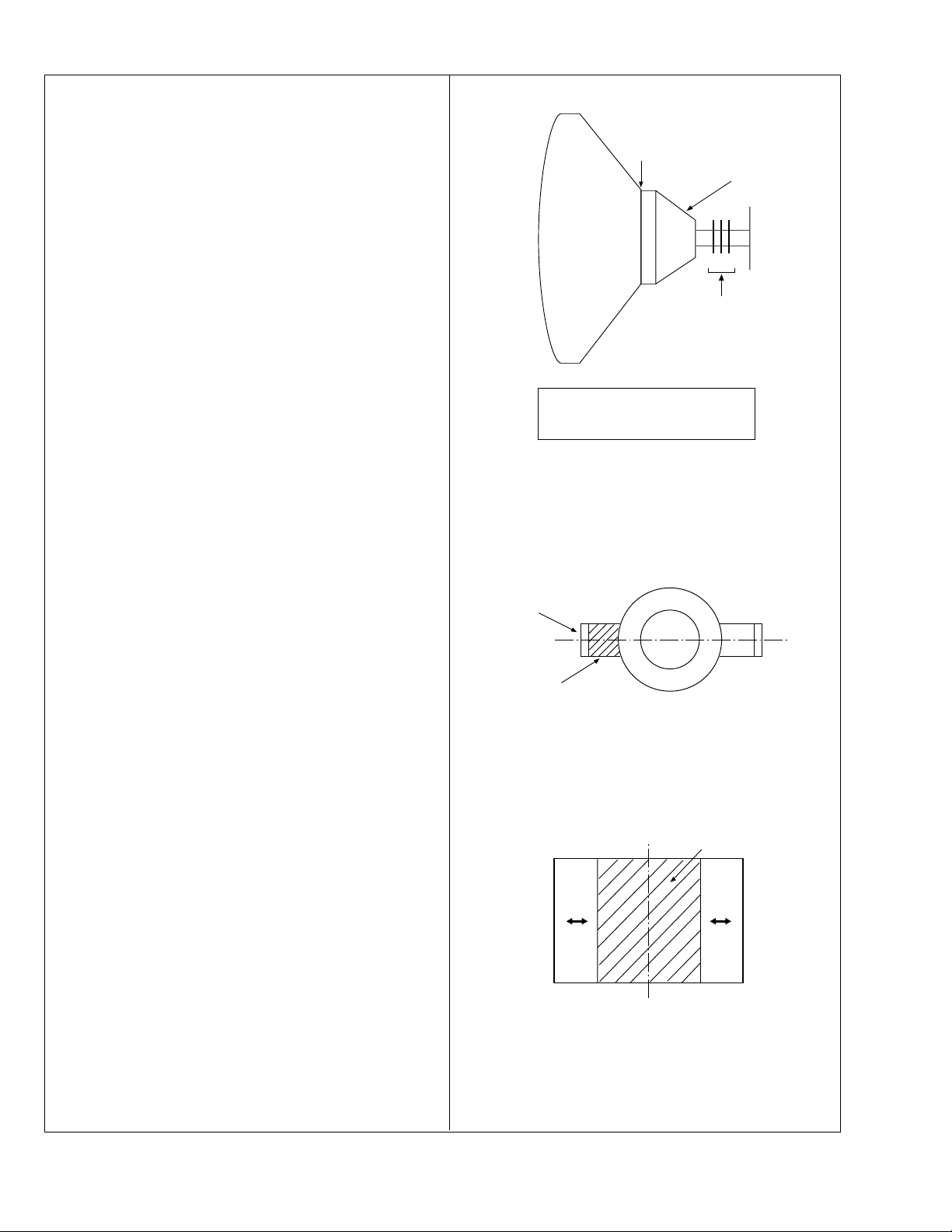
PURITY ADJUSTMENT
Note: The final adjustment of CONVERGENCE must be done after the
FOCUS adjustment. (CONVERGENCE is changed by FOCUS
adjustment.)
When makes difference by FOCUS adjustment, should be
reconfirming PURITY adjustment.
WEDGE
DEFLECTION
YOKE
1. Demagnetize CRT with the demagnetizer.
2. Loosen the retainer screw of the deflection yoke.
3. Remove the wedges.
4. Input a green raster signal from the signal generator, and turn the
screen to green raster.
5. Move the deflection yoke backward.
6. Bring the long lug of the purity magnets on the short lug and position
them horizontally. (Fig. 2)
7. Adjust the gap between two lugs so that the GREEN RASTER will
come into the centre of the screen. (Fig. 3)
8. Move the deflection yoke forward, and fix the position of the deflection yoke so that the whole screen will become green.
9. Insert the wedge to the top side of the deflection yoke so that it will
not move.
10. Input a crosshatch signal.
11. Verify that the screen is horizontal.
P
CRT
4 6
P / C
MAGNETS
• P/C MAGNETS
P : PURITY MAGNET
4 : 4 POLES (convergence magnets)
6 : 6 POLES (convergence magnets)
Fig. 1
PURITY MAGNETS
Long lug
12. Input red and blue raster signals, and make sure that purity is properly adjusted.
Short lug
(FRONT VIEW)
Bring the long lug over the short lug
and position them horizontally.
Fig. 2
GREEN RASTER
CENTRE
Fig. 3
34 No. 51992
Page 35

CONVERGENCE ADJUSTMENT
STATIC CONVERGENCE ADJUSTMENT
AV-34LX
1. Input a crosshatch signal.
2. Using 4-pole convergence magnets, overlap the red and blue lines in
the centre of the screen (Fig. 4) and turn them to magenta (red/blue).
3. Using 6-pole convergence magnets, overlap the magenta(red/blue)
and green lines in the centre of the screen and turn them to white.
4. Repeat 2 and 3 above, and make best convergence.
DYNAMIC CONVERGENCE ADJUSTMENT
1. Using the YH VR on the deflection yoke, match the YH (CROSS). (Fig.
5 and 8)
2. Using the YV VR on the deflection yoke, match the YV. (Fig. 6 and 8)
3. Repeat the steps 1 and 2, obtain an optimum convergence.
4. Differential coil ADJUSTMENT.
In case where the horizontal lines of red and blue around the centre
of both sides of the picture as shown in Fig. 7, adjust the XV difference by using the differential coil on the top of the deflection yoke
(Fig. 8) so as to minimize the XV difference.
(FRONT VIEW)
(FRONT VIEW)
RED
BLUE
RED
BLUE
Fig. 4
YH
GREEN
GREEN
YH
Fig. 5
BLUE
RED
GREENGREEN
BLUE
RED
After adjustment, fix the wedge at the original position.
•
Fasten the retainer screw of the deflection yoke.
Fix the PC magnet with glue.
YV VR YH VR
FRONT
X
V
coil
Fig. 8
(FRONT VIEW)
GREEN GREEN
RED
(FRONT VIEW)
Xv
BLUE
YV
YV
Fig. 6
Fig. 7
BLUE
RED
RED
GREEN
BLUE
BLUE
GREEN
RED
GREEN
No. 51992 35
Page 36

AV-34LX
SELF-CHECK FUNCTIONS
1. Outline
This model has self-check functions given below.When an abnormality has been detected,the SUB POWER is turned off and both ECO and ON
TIMER LEDs flash to inform of the failure.An abnormality is detected by the signal input state of the control line connected to the microcomputer.
2. Self check items
Check item Details of detection Method of detection State of abnormality
Over-current protection
An over-current on the low B line
is detected.
CRT NECK protection
Operation of CRT NECK protection circuit
3. Self check indicating function
When an abnormality has been detected at about 5 seconds after
the power is turned on,the SUB POWER is turned off immediately
and the LEDs flash.
The main microcomputer detects
the possible abnormality at 30msec.intervals and judges the
results in every 16 time. Of the
16 times, if NG is detected more
than 9 times, it is judged that
there is an abnormality.
DITTO
After about
5 seconds
Powe r on
Start of
detection
When an abnormality has been
detected, the SUB-POWER is
turned off. While the SUBPOWER is being turned off, the
POWER key on the remote control unit is not operational until the
power cord is taken out and put
in again.
DITTO
Detection of
an abnormality
Flashing LEDs
SUB-POWER OFF
[ Indication by the LEDs]
Item LEDs flashing intervals Priority of detection
1 Over-current protection At 0.2-second intervals 1
2 CRT NECK protection At 1-second intervals 2
Note: In case of 1 + 2, the item 1 is indicated.
36 No. 51992
Page 37

VICTOR COMPANY OF JAPAN, LIMITED
HOME AV NETWORK BUSINESS UNIT 12, 3-chome, Moriya-cho, kanagawa-ku, Yokohama, kanagawa-prefecture, 221-8528, Japan
AV34LXU-H #4
Printed in Japan
VP0203
SW
 Loading...