

Page 1
A
SERVICE MANUAL
COLOR TELEVISION
AV-32220
/G
V-32220
BASIC CHASSIS
GF3
AV-32220
AV-32220
/H
/M
CONTENTS
!
SPECIFICATIONS
!
SAFETY PRECAUTIONS
!
FEATURES
!
MAIN DIFFERENCE LIST
!
HOW TO IDENTIFY MODELS
!
FUNCTIONS
!
SPECIFIC SERVICE INSTRUCTIONS
!
SERVICE ADJUSTM ENTS
!
PARTS LIST
★
OPERATING INSTRUCTIONS
★
STANDARD CIRCUIT DIAGRAM
1
・・・・・・・・・・・・・・・・・・・・・・・・・・・・・・・・
・・・・・・・・・・・・・・・・・・・・・・・・・・・・・・・・ ・・・・・・・・・・・・・・・・・・・・・・・・・・・・・・・・
・・・・・・・・・・・・・・・・・・・・・・・・・・・・・・・・・・・・・・・・・・・・・・・・・・・・・・・・・・・・・・・・
・・・・・・・・・・・・・・・・・・・・・・・・・・・・・・・・
・・・・・・・・・・・・・・・・・・・・・・・・・・・・・・・・ ・・・・・・・・・・・・・・・・・・・・・・・・・・・・・・・・
・・・・・・・・・・・・・・・・・・・・・・・・・・・・・・・・・・・・・・・・・・・・・・・・・・・・・・・・・・・・・・・・
・・・・・・・・・・・・・・・・・・・・・・・・・・・・・・・・
・・・・・・・・・・・・・・・・・・・・・・・・・・・・・・・・ ・・・・・・・・・・・・・・・・・・・・・・・・・・・
・・・・・・・・・・・・・・・・・・・・・・・・・・・・・・・・・・・・・・・・・・・・・・・・・・・・・・・・・・・・・・・・
・・・・・・・・・・・・・・・・・・・・・・・・・・・・・・・・ ・・・・・・・
・・・・・・・・・・・・・・・・・・・・・・・・・・・・・・・・・・・・・・・・・・・・・・・・・・・・・・・・・・・・・・・・
・・・・・・・・・・・・・・・・・・・・・・・・・・・・・・・・
・・・・・・・・・・・・・・・・・・・・・・・・・・・・・・・・ ・・・・・・・・・・・・・・・・・・・・・・・・・・・
・・・・・・・・・・・・・・・・・・・・・・・・・・・・・・・・・・・・・・・・・・・・・・・・・・・・・・・・・・・・・・・・
・・・・・・・・・・・・・・・・・・・・・・・・・・・・・・・・
・・・・・・・・・・・・・・・・・・・・・・・・・・・・・・・・ ・・・・・・・・・・・・・・・・・・・・・・・
・・・・・・・・・・・・・・・・・・・・・・・・・・・・・・・・・・・・・・・・・・・・・・・・・・・・・・・・・・・・・・・・
・・・・・・・・・・・・・・・・・・・・・・・・・・・・・・・・
・・・・・・・・・・・・・・・・・・・・・・・・・・・・・・・・ ・・・・・・・・・・・・・・・・・・・・・・・・・・・・・・・・
・・・・・・・・・・・・・・・・・・・・・・・・・・・・・・・・・・・・・・・・・・・・・・・・・・・・・・・・・・・・・・・・
・・・・・・・・・・・・・・・・・・・・・・・・・・・・・・・・
・・・・・・・・・・・・・・・・・・・・・・・・・・・・・・・・ ・・・・・・・・・・・・・・・・・
・・・・・・・・・・・・・・・・・・・・・・・・・・・・・・・・・・・・・・・・・・・・・・・・・・・・・・・・・・・・・・・・
・・・・・・・・・・・・・・・・・・・・・・・・・・・・・・・・
・・・・・・・・・・・・・・・・・・・・・・・・・・・・・・・・ ・・・・・・・・・・・・・・・・・・・・・・・・
・・・・・・・・・・・・・・・・・・・・・・・・・・・・・・・・・・・・・・・・・・・・・・・・・・・・・・・・・・・・・・・・
・・・・・・・・・・・・・・・・・・・・・・・・・・・・・・・・
・・・・・・・・・・・・・・・・・・・・・・・・・・・・・・・・ ・・・・・・・・・・・・・・・・・・・・・・・・・・・・・・・・
・・・・・・・・・・・・・・・・・・・・・・・・・・・・・・・・・・・・・・・・・・・・・・・・・・・・・・・・・・・・・・・・
・・・・・・・・・・・・・・・・・・・・・・・・・・・・・・・・
・・・・・・・・・・・・・・・・・・・・・・・・・・・・・・・・ ・・・・・・・・・・・・・・・・・・
・・・・・・・・・・・・・・・・・・・・・・・・・・・・・・・・・・・・・・・・・・・・・・・・・・・・・・・・・・・・・・・・
COPYRIGHT © 2001 VICTOR COMPANY OF JAPAN, LTD.
・・・・・・・・・・・・・・・・・・・・・・・・・・・・・・・・ ・・・・
・・・・・・・・・・・・・・・・・・・・・・・・・・・・・・・・・・・・・・・・・・・・・・・・・・・・・・・・・・・・・・・・
・・・・・・・・・・・・・・・・・・・・・・・・・・・
・・・・・・・・・・・・・・・・・・・・・・・・・・・・・・・・・・・・・・・・・・・・・・・・・・・・・・
・・・・・・・・・・・・・・・・・・・・・・・・・・・
・・・・・・・・・・・・・・・・・・・・・・・・・・・・・・・・・・・・・・・・・・・・・・・・・・・・・・
・・・・・・・・・・・・・・・・・・・・・・・
・・・・・・・・・・・・・・・・・・・・・・・・・・・・・・・・・・・・・・・・・・・・・・
・・・・・・・・・・・・・・・・・・・・・・・・・・・・・・・・ ・・・・・・
・・・・・・・・・・・・・・・・・・・・・・・・・・・・・・・・・・・・・・・・・・・・・・・・・・・・・・・・・・・・・・・・
・・・・・・・・・・・・・・・・・
・・・・・・・・・・・・・・・・・・・・・・・・・・・・・・・・・・
・・・・・・・・・・・・・・・・・・・・・・・・
・・・・・・・・・・・・・・・・・・・・・・・・・・・・・・・・・・・・・・・・・・・・・・・・
・・・・・・・・・・・・・・・・・・・・・・・・・・・・・・・・ ・・・・
・・・・・・・・・・・・・・・・・・・・・・・・・・・・・・・・・・・・・・・・・・・・・・・・・・・・・・・・・・・・・・・・
・・・・・・・・・・・・・・・・・・
・・・・・・・・・・・・・・・・・・・・・・・・・・・・・・・・・・・・
・・・・・・・
・・・・・・・・・・・・・・
・・・・・・
・・・・・・・・・・・・
・・・・
・・・・・・・・
2-1
2
3
4
4
4
5
6
13
31
No.51782
Jan. 2001
Jan. 2001
Page 2
A
V-32220
SPECIFICATIONS
Items Contents
Dimensions (W
Mass
TV System and Color system
TV RF System
Color System
Sound System
TV Receiving Channels and Frequency
VL Band
VH Band
UHF Band
CATV Receiving Channels and Frequency
Low Band
High Band
Mid Band
Super Band
Hyper Band
Ultra Band
Sub Mid Band
TV/CATV Total Channel
Intermediate Frequency
Video IF Carrier
Sound IF Carrier
Color Sub Carrier
Power Input
Power Consumption
Picture Tube
High Voltage
Speaker
Audio Power Output
INPUT
S-Video
Video
Audio
Audio Output
(Variable / Fix : Selectable)
AV Compu link EX Input
Antenna terminal
Remote Control Unit
××××H××××
D)
30-1/4”×26-1/4”×21-1/2” inch / (768mm×667mm×547mm)
112.2lbs (51.0kg)
CCIR(M)
NTSC
BTSC (Multi Channel Sound)
(02~06) 54MHz~88MHz
(07~13) 174MHz~216MHz
(14~69) 470MHz~806MHz
(02~06, A-8) by (02~06&01)
(07~13) by (07~13)
(A~1) by (14~22)
(J~W) by (23~36)
(W+1~W+28) by (37~64)
(W+29~W+84) by (65~125)
(A8, A4~A1) by (01, 96~99)
180 Channels
45.75 MHz
41.25 MHz (4.5MHz)
3.58 MHz
120V AC, 60Hz
125W / 1.8A
32” (80cm) measured diagonally, Ful l Square
31.0kV±1.3kV (at zero beam current )
2”×4-3/4” / 5×12cm Oblong type×2
3W+3W
Y : 1Vp-p positive (negative sync provided, when term i nated with 75Ω)
C : 0.286Vp-p (burst signal, when terminated with 75Ω)
1Vp-p 75Ω (RCApin jack)
500mVrms (-4dBs ), High Impedance (RCA pin jack)
Variable: More then 0~1550mVrms (+6dBs)
Low Impedance (400Hz when modulated 100%) (RCA pin jack)
Fix : 500mVrms(-4dBs)
Low Impedance (400Hz when modulated 100%) (RCA pin jack)
3.5mm mini jack
75Ω (VHF/UHF) Termi nal , F-Type Connector
RM-C306-1A (AA/R6/UM-3 battery×2)
Design & specifications are subject to change without notice.
(54MHz
~
804MHz)
2
No.51782
Page 3
A
SAFETY PRECAUTIONS
1. The design of this product contains special hardware, many
circuits and components specially for safety purposes. For
continued protection, no changes should be made to the
original design unless authorized in writing by the manufacturer.
Replacement parts must be identical to those used in the
original circuits. Service should be performed by qualified
personnel only.
2. Alterations of the design or circuitry of the products should not
be made. Any design alterations or additions will void the
manufacturer's warranty and will further relieve the
manufacturer of responsibility for personal injury or property
damage resulting therefrom.
3. Many electrical and mechanical parts in the products have
special safety-related characteristi cs. These charact eris t ics are
often not evident from visual inspection nor c an the protection
afforded by them necessarily be obtained by using
replacement components rated for higher voltage, wattage, etc.
Replacement parts which have these special safety
characteristics are identified in the parts list of Service manual.
Electrical components having such features are identified
by shading on the schematics and by (
in Service manual.
does not have the same safety characteristics as the
recommended replacement part shown in the parts list of
Service manual may cause shock, fire, or other hazards.
4.
Use isolation transformer when hot chassis.
The chassis and any sub-chassis contained in some products
are connected to one side of the AC power line. An isolation
transformer of adequate capacity should be inserted between
the product and the AC power supply point while performing
any service on some products when the HOT chassis is
exposed.
5.
Don't short between the LIVE side ground and ISOLATED
(NEUTRAL) side ground or EARTH side ground when
repairing.
Some model's power circuit is partly diff erent in the GND. The
difference of the GND is shown by the LIVE : (") side GND,
the ISOLATED(NEUTRAL) : (#) side GND and EARTH : ($)
side GND. Don't short between the LIVE side GND and
ISOLATED(NEUTRAL) side GND or EARTH side GND and
never measure with a measuring apparatus (oscilloscope etc.)
the LIVE side GND and ISOLATED(NEUTRAL) side GND or
EARTH side GND at the same time.
If above note will not be kept, a fuse or any parts will be broken.
6. If any repair has been made to the chassis, it is recommended
that the B1 setting should be checked or adjusted (See
ADJUSTMENT OF B1 POWER SUPPLY).
7. The high voltage applied to the picture tube must conform with
that specified in Service manual. Excessive high voltage can
cause an increase in X-Ray emission, arcing and possible
component damage, therefore operation under excessive high
voltage conditions should be kept to a minimum, or should be
prevented. If severe arcing occurs, remove the AC power
immediately and determine the cause by visual inspection
(incorrect installation, cracked or melted high voltage harness,
poor soldering, etc.). To maintain the proper minimum level of
soft X-Ray emission, components in the high voltage circuitry
including the picture tube must be the exact replacements or
alternatives approved by the manufacturer of the complete
product.
8. Do not check high voltage by drawing an arc. Use a high
voltage meter or a high voltage probe with a VTVM. Discharge
the picture tube before attempting meter connection, by
connecting a clip lead to the ground frame and connecting the
other end of the lead through a 10kΩ 2W resistor to the anode
button.
9. When service is required, observe the original lead dress.
Extra precaution should be given to assure correct lead dress
in the high voltage circuit area. Where a short circuit has
occurred, those components that indicate evidence of
overheating should be replaced. Always use the
manufacturer's replacement components.
The use of a substitute replacement which
!!!!
) on the parts list
V-32220
10.
Isolation Check
(Safety for Electrical Shock Hazard)
After re-assembling the product, always perform an isolation
check on the exposed metal parts of the cabinet (antenna
terminals, video/audio input and output terminals, Control
knobs, metal cabinet, screwheads, earphone jack, control
shafts, etc.) to be sure the product is safe to operate without
danger of electrical shock.
(1)
Dielectric Strength Test
The isolation between the AC primary circuit and all metal parts
exposed to the user, particularly any exposed metal part having
a return path to the chassis should withstand a voltage of
1100V AC (r.m.s.) for a period of one second.
(. . . . Withstand a voltage of 1100V AC (r.m.s.) to an appliance
rated up to 120V, and 3000V AC (r.m.s.) to an appliance rated
200V or more, for a period of one second.)
This method of test requires a test equipment not generally
found in the service trade.
(2)
Leakage Current Check
Plug the AC line cord directly into the AC outlet (do not use a
line isolation transformer during this check.). Using a " Leakage
Current Tester", measure the leakage current from each
exposed metal part of the cabinet, particularly any exposed
metal part having a return path to the chassis, to a known good
earth ground (water pipe, etc.). Any leakage c urrent must not
exceed 0.5mA AC (r.m.s.).
However, in tropical area, this must not exceed 0.2mA AC
(r.m.s.).
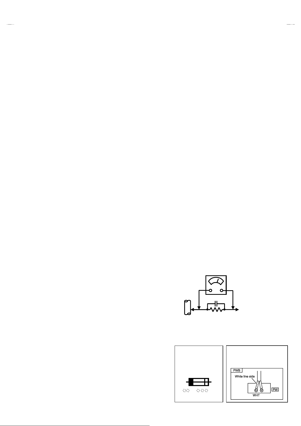
""""
Alternate Check Method
Plug the AC line cord directly into the AC outlet (do not use a
line isolation transformer during this check.). Use an AC
voltmeter having 1000 ohms per volt or more sensitivi ty in the
following manner. Connect a 1500Ω 10W resistor paralleled
by a 0.15μF AC-type capacitor between an exposed metal
part and a known good earth ground (water pipe, etc.).
Measure the AC voltage across the resistor with the AC
voltmeter. Move the resistor connection t o each exposed metal
part, particularly any exposed metal part having a return path to
the chassis, and measure the AC voltage across the res istor.
Now, reverse the plug in the AC outlet and repeat each
measurement. Any voltage measured must not exceed 0.75V
AC (r.m.s.). This corresponds to 0.5mA AC (r.m.s.).
However, in tropical area, this must not exceed 0.3V AC
(r.m.s.). This corresponds to 0.2mA AC (r.m.s.).
AC VOLTMETER
(HAVING 1000
GOOD
EARTH
GROUND
11.
High voltage hold down circuit check.
After repair of the high voltage hold down circuit, this circuit
shall be checked to operate correctly.
See item "
circuit
This mark shows a fast
operating fuse, the
letters indicated below
show the rating.
0.15μF AC-TYPE
Ω
10W
1500
How to check the high voltage hold down
".
OR MORE SENSITIVITY)
PLACE THIS PROBE
ON EACH EXPOSED
METAL PART
POWER CORD
REPLACEMENT WARNING.
Connecting the white line side of power
cord to “WHT” character side.
Ω
/V,
A V
No. 51782
3
Page 4
A
V-32220
FEATURES
"
New chassis design enables use of a main board with
simplified circuitry.
"
Digital comb filter Improved picture quality.
"
Full-s quare CRT (cathode ray tube) reproduces fine textured
picture in every detail.
"
Closed-caption broadcasts can be viewed.
"
With AUDIO. VIDEO INPUT terminal.
2
"
I
C bus control utilizes single chip ICs.
MAIN DIFFERENCE LIST
Model
!
Part name
MAIN PWB
PICTURE TUBE
!
DEG.COIL
!
AV-32220
SGF-1017A-M2 SGF-1002A-M2 SGF-1003A-M2
A80QCF240X14L A80LJF30X08(G) M80JUA061X06
QQW0086-001 CELD066-002JA
/G
"
S-VIDEO input terminal for taking best advantage of Super
VHS.
"
Variable / Fix audio output terminal.
"
With AV COMPU LINK EX terminal.
AV-32220
/H
AV-32220
/M
←
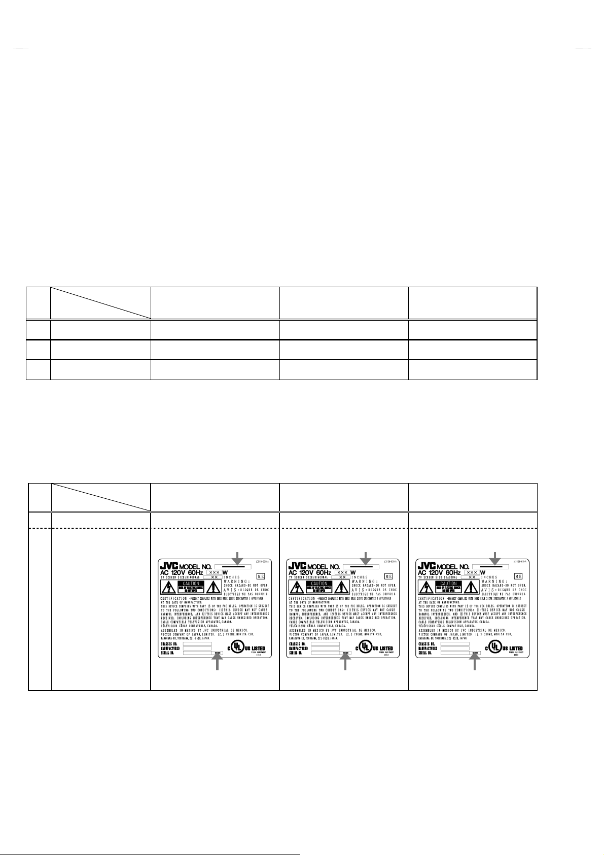
HOW TO IDENTIFY MODELS
The difference between
As the result of the difference in
!
Parts name
RATING LABEL LC31139-001A-A
!
AV-32220/G, AV-32220/H
PICTURE TUBE
MODEL
AV-32220
INDICATED AV-32220 INDICATED AV-32220 INDICATED AV-32220
INDICATED
and
AV-32220/M
, the
MAIN PWB
/G
““““G””””
is in the
also differ.
PICTURE TUBE
AV-32220
←←←←
INDICATED
/H
““““H””””
.
AV-32220
/M
←←←←
INDICATED
““““M””””
4
No. 51782
Page 5
A
FUNCTIONS
V-32220
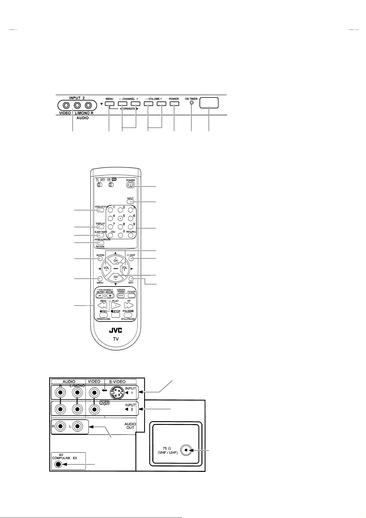
FRONT PANEL
① ② ⑤④ ⑥ ⑦
REMOTE CONTROL UNIT
④
⑤
⑥
⑦
⑧
⑩
⑭
③
①
②
③
⑫
⑨
⑬
⑪
①
INPUT 2(V, L, R)
②
MENU CONTROL KEY
③
CHANNEL UP/DOWN KEYS
④
VOLUME UP/DOWN KEYS
⑤
POWER BUTTON
⑥
ON TIMER LAMP
⑦
REMOCON WINDOW
①
POWER BUTTON
②
INPUT SELECT KEY
③
CHANNEL KEYS
④
VIDEO STATUS KEY
⑤
DISPLAY KEY
⑥
SLEEP TIMER KEY
⑦
HYPER SURROUND KEY
⑧
MUTING KEY
⑨
V-CHIP KEY
⑩
MENU KEY
⑪
EXIT KEY
⑫
VOLUME UP/DOWN KEYS
⑬
CHANNEL UP/DOWN KEYS
⑭
VCR CONTROL KEYS
REAR PANEL
①
①
INPUT 1(S, V, L, R)
②
INPUT 2(V, L, R)
②
③
⑤
④
No. 51782
③
AUDIO OUTPUT
④
AV COMPULINK EX JACK
⑤
AERIAL SOCKET
5
Page 6
A
V-32220
SPECIFIC SERVICE INSTRUCTIONS
DISASSEMBLY PROCEDURE
REMOVING THE REAR COVER
"
Unplug the power supply cord.
1. Remove the 11 screws marked
2. Remove the rear cover toward you.
*
When reinstalling the rear cover, carefully push it inward after
inserting the chassis into the rear cover groove.
as shown in Fig.2.
AAAA
REMOVING THE CHASSIS
"
After removing the rear cover.
1. Slightly raise the both sides of the chassis by hand and remove
the 2 claws under the both sides of the chassis from the front
cabinet.
2. Draw the chassis backward along the rail in the arrow direction
marked
(If necessary, take off the wire clamp, connector’s etc.)
*
When conducting a check with power supplied, be sure to
confirm that the CRT earth wire is connected to the CRT
SOCKET PWB and the MAIN PWB.
as shown in the Fig.2.
BBBB
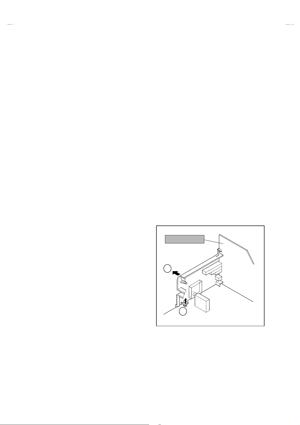
REMOVING THE TERMINAL BOARD
"
After removing the rear cover.
1. Remove the 3 screws marked
2. After removing the claw marked
mark as shown in Fig.1.
3. When you pull out the TERMINAL BOARD in the direct ion of
arrow marked
as shown in Fig.1, it can be removed.
FFFF
as shown in Fig.2.
CCCC
in the direction of arrow
EEEE
CHECKING THE MAIN PW BOARD
1. To c heck t he backsi de of t he MAIN PW Board.
(1) Pull out the chassis. (Refer to REMOVING THE CHASSIS).
(2) Erect the chassis vertically so that you can easily check the
backside of the MAIN PW Board.
[CAUTION]
When erecting the chassis, be careful so that there will be no
•
contacting with other PWB.
Before turning on power, make sure that the CRT earth wire and
•
other connectors are properly connected.
WIRE CLAMPING AND CABLE TYING
1. Be sure to clamp the wire.
2. Never remove the cable tie used for tying the wires together.
Should it be inadvertently removed, be sure t o tie the wires with
a new cable tie.
TERMINAL BOARD
REMOVING THE FRONT CONTROL PW BOARD
"
After removing the rear cover and chassis.
1. Remove the 2 screws marked
2. Then remove the FRONT CONTROL PWB.
as shown in Fig.2.
DDDD
REMOVING THE SPEAKER
"
After removing the rear cover and chassis.
1. Remove the 2 screws marked
2. Follow the same steps when removing the other hand speaker.
as shown in Fig.2.
GGGG
F
E
Fig. 1
6
No. 51782
Page 7
A
V-32220
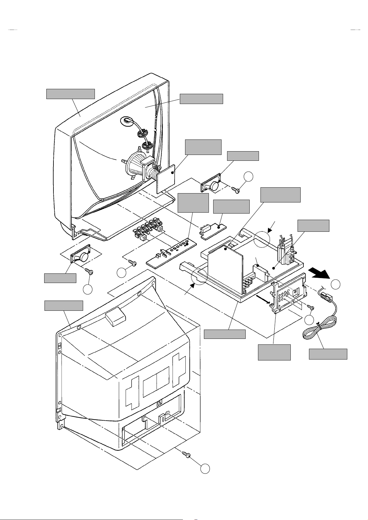
FRONT CABINET
PICTURE TUBE
CRT SOCKET
PWB
FRONT
CONTROL
PWB
SPEAKER
G
AV SELECTOR
PWB
FRONT JACK
PWB
CLAW
MAIN PWB
TUNER
SPEAKER
REAR COVER
D
B
G
CLAW
C
CHASSIS BASE
TERMINAL
BOARD
POWER CORD
A
Fig.2
No. 51782
7
Page 8
A
V-32220
A
A
A
A
A
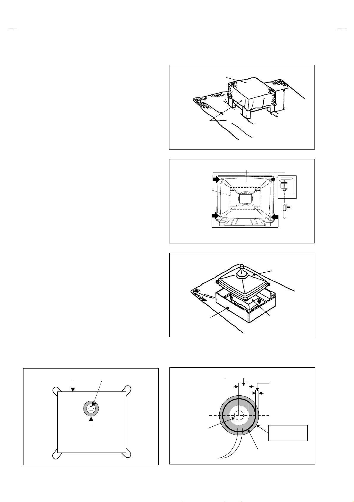
REMOVING THE CRT
Replacement of the CRT should be performed by 2 or more
!
persons.
After removing the rear cover, chassis etc.,
"
1. Putting the CRT change table on soft cloth, the CRT change
table should also be covered with such soft cloth (shown in
Fig.3).
2. W hile keeping the surface of CRT down, mount the TV set on
the CRT change table balanced will as shown in Fig.4.
3. Remove 4 screws marked by arrows with a box type
screwdriver as shown in Fig.4.
Since the cabinet will drop when screws have been removed,
"
be sure to support the cabinet with hands.
4. After 4 screws have been rem oved, put the cabinet slowly on
cloth (At this time, be carefully so as not to damage the front
surface of the cabinet) shown in Fig.5.
The CRT should be assembled according to the opposite
"
sequence of its dismounting steps.
The CRT change table should preferably be smaller that the
!
CRT surface, and its height be about 35cm.
CRT CHANGE TABLE
PPROX.
35cm
CLOTH
Fig. 3
CRT
CRT
CHANGE
TABLE
BOX
TYPE
SCREW
DRIVER
COATING OF SILICON GREASE FOR ELECTRICAL
INSULATION ON THE CRT ANODE CAP SECTION.
Subsequent to replacement of the CRT and HV transformer or
"
repair of the anode cap, etc. by dismounting them, be sure to
coat silicon grease for electrical insulation as shown in Fig.6.
Wipe around the anode button with clean and dry cloth. (Fig.6)
Coat silicon grease on the section around the anode button. At
this time, take care so that any silic on greases dose not sticks
to the anode button. (Fig.7)
★★★★
Silicon grease product No. KS - 650N
CRT
node button
CABINET
pprox.
20mm (Do not
coat grease on
this section
Fig. 4
CRT
CRT
CHANGE TABLE
Fig. 5
Silicon grease
should be coated
by 5mm or more
from the outside
diameter of anode
cap.
Silicon grease
coating
Fig. 6 Fig. 7
8
No. 51782
node button
(No sticking of
silicon grease)
Coating position
of silicon grease
node cap
Page 9
A
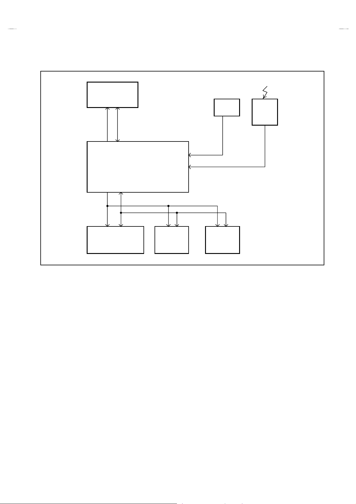
SYSTEM BLOCK DIAGRAM
IC702
MEMORY
SDA1SCL1
IC701
MAIN MICON
SDA3SCL3
AFC
V-32220
IF
Remote
control
unit
IC601
MTS, TONE
SURROUND CONTROL
IC201
1 CHIP
CONTROL
TU001
TUNER
No.51782
9
Page 10
A
V-32220
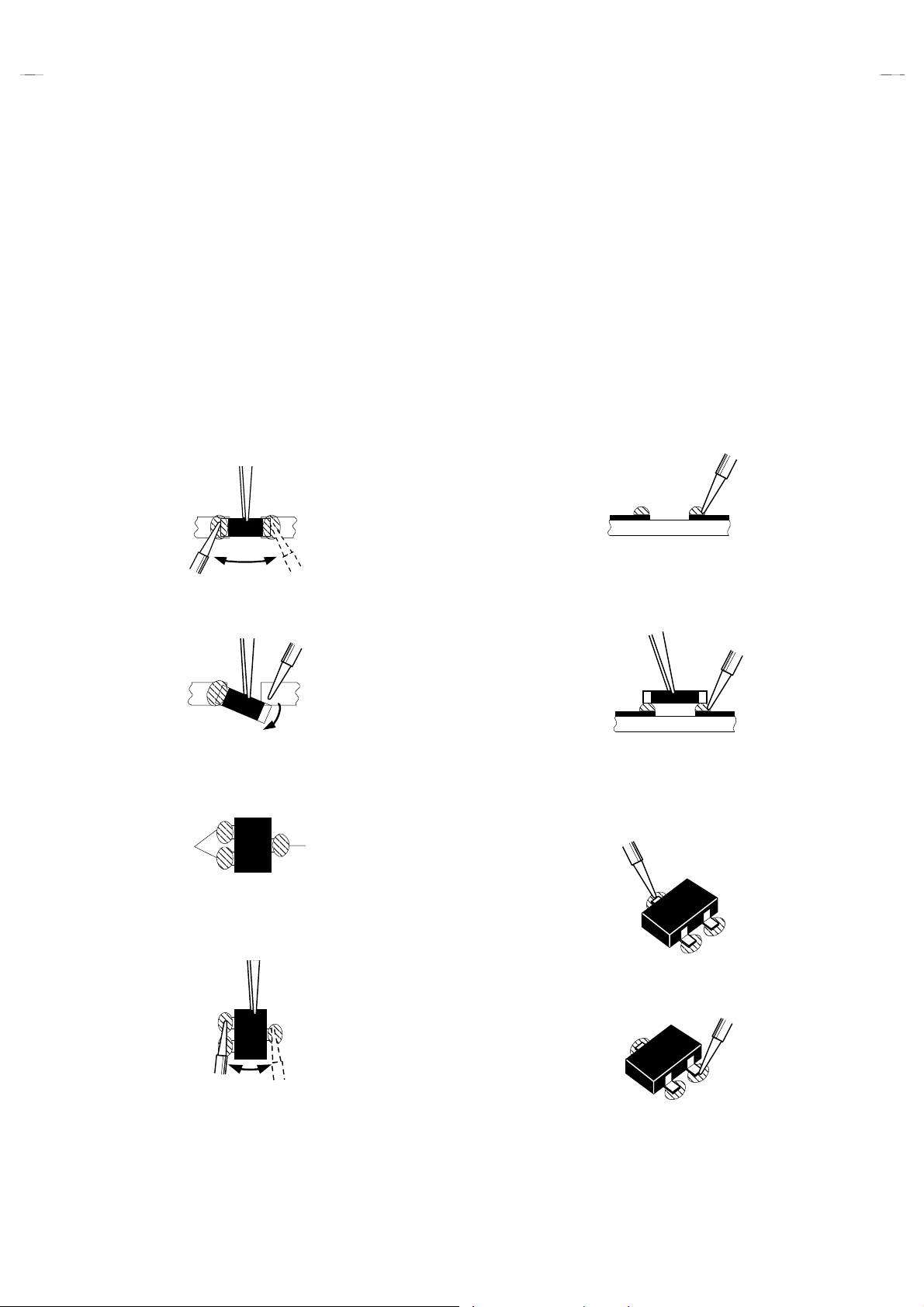
REPLACEMENT OF CHIP COMPONENT
!
CAUTIONS
1. Avoid heating for more than 3 seconds.
2. Do not rub the electrodes and the resist parts of the pattern.
3. When removing a chip part, melt the solder adequately.
4. Do not reuse a chip part after removing it.
!
SOLDERING IRON
1. Use a high insulation soldering iron with a thin pointed end of it.
2. A 30w soldering iron is recommended for easily removing parts.
!
REPLACEMENT STEPS
How to remove Chip parts
1.
####
Resistors, capacitors, etc
(1) As shown in the figure, push the part with tweezers and
alternately melt the solder at each end.
(2) Shift with tweezers and remove the chip part.
####
Transistors, diodes, variable resistors, etc
(1) Apply extra solder to each lead.
SOLDER
SOLDER
2. How to install Chip parts
####
Resistors, capacitors, etc
(1) Appl y solder to the pattern as indicated in the figure.
(2) Gras p the chip part with tweezers and place it on the solder.
Then heat and melt the solder at both ends of the chip part.
####
Transistors, diodes, variable resistors, etc
(1) Appl y solder to the pattern as indicated in the figure.
(2) Grasp the chip part with tweezers and place it on the solder.
(3) First solder lead
as indicated in the figure.
A
A
(2) As shown in the figure, push the part with tweezers and
alternately melt the solder at each lead. Shift and remove the
chip part.
Note : After removing the part, remove remaining solder from the
pattern.
10
No.51782
(4) Then solder leads
and C.
B
C
A
C
B
B
Page 11

A
MEMORY IC REPLACEMENT
(CW)
1. Memory IC
This model uses a memory IC.
This memory IC stores data for proper operation of the video and deflection circuits.
When replacing, be sure to use an IC containing this (initial value) data.
2. Memory IC replacement procedure
Procedure Screen display
(1) Power off
Switch off the power and disconnect the power cord from the outlet.
(2) Replace the memory IC
Initial value must be entered into the new IC.
(3) Power on
Connect the power cord to the outlet and switch on the power.
V-32220
(4) System constant check and setting
It must not adjustment
1) Press
SLEEP TIMER
” is being displayed, press
MIN.
key and, while the indication of “
DISPLAY
key and
VIDEO STATUS
SLEEP TIMER 0
on the remote control unit simultaneously.
2) The SERVICE MENU screen of Fig.1 is displayed.
3) While the SERVICE MENU is displayed, again simultaneously press
the
DISPLAY
and
VIDEO STATUS
keys to display the Fig.2 SYSTEM
CONSTANT screen.
4) Refer to the SYSTEM CONSTANT table and check t he setting items.
Where these differ, select t he setting item with the
key and adjust the setting with the
MENU LEFT/RIGHT
MENU UP/DOWN
keys. (The
letters of the selected item are displayed in yellow.)
5) After adjusting, release the
MENU LEFT/RIGHT
key to store the setting
value.
6) Press the
key twice to return the normal screen.
EXIT
(5) Receive channel setting
Refer to the OPERATING INSTRUCTIONS (USER'S GUIDE) and set
the receive channels (Channels Preset) as described.
key
SERVICE MENU
PICTURE SOUND
THEATER OTHERS
LOW LIGHT HIGH LIGHT
RF AFC
VCO
SELECT BY
OPERATE BY EXIT BY
I2C BUS CTRL
Fig.1
SYSTEM CONSTANT
MODEL : XX-XXXXX
CCD : YES
BBE : NO
V-CHIP : YES
CAN V-CHIP : NO
XXXXXXXXX XXX
SELECT BY
OPERATE BY EXIT BY
Fig.2
EX
IT
EX
IT
(6) User settings
Check the user setting items according to Table 2.
Where these do not agree, refer to the OPERATING INSTRUCTIONS
(USER'S GUIDE) and set the items as described.
(7) SERVICE MENU setting
Verify what to set in the SERVICE MENU, and set whatever is
necessary. (Fig.1) Refer to the SERVICE ADJUS T MENT for setting .
No. 51782
11
Page 12

A
V-32220
TABLE 1 (System Constant setting)
Setting item Setting constant Setting value
MODEL
CCD
BBE
V-CHIP
CAN V-CHIP
TABLE 2 (User setting)
Setting item Setting value Setting item Setting value
1. Use remote controller keys
POWER
CHANNEL
VOLUME
TV/VIDEO
HYPER SURROUND
Display the each application model
OFF
CH-02
Proper sound volume
TV
OFF
YES NO
YES NO
YES NO
YES NO
DISPLAY
VIDEO STATUS
SLEEP TIMER
Comformable model name
YES
NO
YES
YES
OFF
STANDARD
0
2. Settings of MENU with remote control keys
PICTURE ADJUST
TINT
COLOR
PICTURE
BRIGHT
DETAIL
NOISE MUTING
SET VIDEO STATUS
SOUND ADJUST
BASS
TREBLE
BALANCE
MTS
CLOCK / TIMERS
SET CLOCK
ON/OFF TIMER
CENTER
CENTER
CENTER
CENTER
CENTER
ON
ALL CENTER
CENTER
CENTER
CENTER
STEREO
Unnecessary to set
NO
INITIAL SETUP
TV SPEAKER
AUDIO OUT
LANGUAGE
CLOSED CAPTION
AUTO TUNER SET UP
CHANNEL SUMMARY
SET LOCK CODE
ON
FIX
ENG
OFF
TUNER MODE : AIR
Unnecessary to set
Unnecessary to set
12
No. 51782
Page 13

A
V-32220
SERVICE ADJUSTMENT
ADJUSTMENT PREPARATION
1. You can make the necessary adjustments for this unit with either the remote control unit or with the adjustment equipment and
parts as given below.
2. Adjustment with the remote control unit is made on the basis of the initial setting values, however, the new setting values which
set the screen to its optimum condition may differ from the initial settings.
3. Make sure that AC power is turned on correctly.
4. Turn on the power for the set and test equipment before use, and start the adjustment procedures after waiting at least 30 minutes.
5. Unless otherwise specified, prepare the most suitable reception or input signal for adjustment.
6. Never touch any adjustment parts, which are not specif i ed in the list for this adj ustment-variabl e resistors, transformers, condensers, etc.
7. Presetting before adjustment.
Unless otherwise specified in the adjustment instructions, preset t he following functions with the remote control unit.
""""
User mode setting position
(1) VIDEO STATUS STANDARD
(2) HYPER SURROUND OFF
(3) BASS, TREBLE, BALANCE CENTER
(4) TINT, COLOR, PICTURE, BRIGHT, DETAIL CENTER
MEASURING INSTRUMENT
1. DC voltmeter(or digital voltmeter)
2. Oscilloscope
3. Signal generator ( Pattern generator ) [NTSC]
4. Remote control unit
5. TV audio multiplex signal generator
6. Frequency counter
ADJUSTMENT ITEMS
●
Check of B1 POWER SUPPLY
●
IF VCO adjustment
●
RF AGC adjustment
●
FOCUS adjustment
●
DEFLECTION adjustment
V. CENTER, V. SIZE, V. POSITION adjustment
H. WIDTH, SIDEPIN CORRECT and H. POSITION
adjustment
●
VIDEO / CHROMA adjustment
WHITE BALANCE (Low light) adjustment
WHITE BALANCE (High light) adjustment
SUB BRIGHT adju st ment
SUB CONTRAST adjustment
SUB COLOR adjustment
SUB TINT adjustment
●
MTS circuit adjustment
INPUT LEVEL check
STEREO VCO adjust me nt
SAP VCO adjustment
FILTER check
SEPARATION adjustment
No. 51782
13
Page 14

A
V-32220
(
)
ADJUSTMENT LOCATIONS
MAIN PWB ASS'Y
FRONT
S
AV SELECTOR
PWB
CN001
MPX
D
memory IC
IC702
IC701
CPU
F901(5A)
PW
X
H.WIDTH
SIDEPIN
CORRECT
13
T
FM DET
T161
IC201
TUNER
CW
T131
DEG.
HV
V CENTER SW
S421
U
(BRAIDED ASS'Y)
E1
CRT EARTH
1
3
B1
HVT
HVT
HVTHVT
UPPER : FOCUS
LOWER : SCREEN
TP-E
( )
B1
(TP-91)
CRT SOCKET PWB ASS'Y
(SOLDER SIDE)
TP-R
TP-B
T
TP-E( )
CRT EARTH
(BRAIDED ASS'Y)
14
E2
TOP
U
FRONT CONTROL PWB ASS'Y
POWER MENUVOL CH
IC841
D
-
+-
+
FRONT
FRONT JACK PWB ASS'Y
FRONT
J001
No. 51782
F
Page 15

A
BASIC OPERATION OF SERVICE MENU
(CW)
1. TOOL OF SERVICE MENU OPERATION
Operate the SERVICE MENU with the REMOTE CONTROL UNIT.
2. SERVICE MENU ITEMS
In general, basic setting (adjustments) items or verifications are perf orm ed in the SERVICE MENU.
PICTURE
"
SOUND
"
THEATER
"
OTHERS
"
LOW LIGHT
"
HIGH LIGHT
"
RF AFC
"
VCO (CW)
"
2
C BUS CTRL
I
"
3. Basic Operations of the SERVICE MENU
(1) How to enter the SERVICE MENU.
Press
STATUS
・・・・・・・・・・・・・・・・・・・・
・・・・・・・・・・・・・・・・・・・・・
・・・・・・・・・・・・・・・・・・・
・・・・・・・・・・・・・・・・・・・・
・・・・・・・・・・・・・・・・・・
・・・・・・・・・・・・・・・・・
・・・・・・・・・・・・・・・・・・・・・
・・・・・・・・・・・・・・・・・・・
・・・・・・・・・・・・・・・・
SLEEP TIMER
key and, while the indication of “
This set the setting values (adjustment values) of the VIDEO/CHROMA and DEFLECTION circuits.
This set the setting values (adjustment values) of the AUDIO circuit.
This is used when the THEATER MODE is adjusted.
This is used when the OTHERS MODE is adjusted.
This sets th e setting values (ad justm ent values) of the WHI T E BALAN CE circuit.
This sets th e setting values (ad justm ent values) of the WHI T E BALAN CE circuit.
This is used when the RF AFC MODE is verified.
This is used when the IF VCO is adjusted.
This is used when ON/OFF of the I2C BUS CT RL is set.
SLEEP TIMER 0 MIN.
key on the remote control unit simultaneously to enter the
[Do not adjust]
” is being displayed, press
SERVICE MENU
[Fixed ON]
DISPLAY
key and
screen ① shown in the next figure page.
V-32220
VIDEO
(2) SERVICE MENU screen selection
Press the UP / DOWN key of the MENU to select any of the following items.
(The letters of the selected items are displayed in yellow.)
●
PICTURE
●
THEATER
●
LOW LIGHT
●
RF AFC
●
VCO (CW)
●
SOUND
●
OTHERS
●
HIGH LIGHT
●
I2C BUS CTRL
SERVICE MENU
SERVICE MENU
PICTURE SOUND
THEATER OTHERS
LOW LIGHT HIGH LIGHT
RF AFC
VCO
SELECT BY
OPERATE BY EXIT BY
(MAIN MENU)
I2C BUS CTRL
(3) Enter the any setting ( adjustment ) mode
"
PICTURE, SOUND and OTHERS mode
1) If select any of PICT URE, SOUND or OTHERS items, and the LEFT / RIGHT key is pressed from SERVICE MENU ( MAIN
MENU ), the screen ② will be displayed as shown in figure page later.
2) Then the UP / DOWN key is pressed, the PICTURE mode screen ③ or the SOUND mode screen ④ or t he OTHERS mode
screen ⑤ is displayed, and the PICTURE, SOUND or OTHERS setting can be performed.
"
THEATER, LOW LIGHT, H IGH LIGHT, RF AFC, VCO (CW) and I
1) If select any of THEATER / LOW LIGHT / HIGH LIGHT / RF AFC / VCO (CW) / I
is pressed from SERVICE MENU ( MAIN MENU ), the screens
2
C BUS CTRL mode
6 7 8 ⑨
2
⑩ ⑪
C BUS CTRL items, and the LEFT / RIGHT key
will be displayed as shown in figure page
later.
2) Then the settings or verifications can be performed.
EX
IT
No. 51782
15
Page 16

A
V-32220
(CW)
SERVICE MENU (MAIN MENU)
①①①①
SERVICE MENU
PICTURE SOUND
THEATER OTHERS
LOW LIGHT HIGH LIGHT
RF AFC
VCO
SELECT BY
OPERATE BY
I2C BUS CTRL
EXIT BY
PICTURE MODE
SCREEN
②②②②
EX
IT
SELECT BY
EXIT BY
EX
IT
③③③③
1. BRIGHT
STATUS
***
********
HIGH LIGHT MODE
⑧⑧⑧⑧
HIGH LIGHT
*** ***
RF AFC MODE
⑨⑨⑨⑨
[DO NOT ADJUST ]
RF AFC ON
FINE
STATUS
SELECT BY
OPERATE BY
VCO (CW) MODE
⑩⑩⑩⑩
********
EXIT BY
***
SOUND MODE
④④④④
1. ATTENUATOR
STATUS
EX
IT
THEATER MODE
⑥⑥⑥⑥
***
********
⑤⑤⑤⑤
1. OSD POS.
OTHERS MODE
***
HIGH LEVEL
REFERENCE LEVEL
LOW LEVEL
SYNC : YES
I2C BUS CTRL MODE
⑪⑪⑪⑪
[FIXED ON]
I2C BUS ON
SELECT BY
OPERATE BY
16
EXIT BY
***
***
***
***
***
G DRIVE
B DRIVE
R CUT.
G CUT.
B CUT.
***
TINT
COLOR
PICTURE
BRIGHT
DETAIL
SELECT BY
OPERATE BY
LOW LIGHT MODE
⑦⑦⑦⑦
EX
IT
BRIGHT
*** *** ***
***
***
***
***
***
EXIT BY
EX
IT
No. 51782
Page 17

A
(4) Setting method
1) UP / DOWN key of the MENU
Select the SETTING ITEM.
2) LEFT / RIGHT key of the MENU
Setting (adjust) the SETTING VALUE of the SETTING ITEM.
When the key is released the SETTING VALUE will be stored
(memorized).
3) EXIT key
Returns to the previous screen.
(5) Releasing SERVICE MENU
1) A fter returning to the SERVICE MENU upon completion of the setting
(adjustment) work, press the EXIT key again.
SETTING
ITEM
1. BRIGHT
STATUS
PICTURE MODE
***
********
INITIAL
SETTING VALUE
↓ (Adjust)
SETTING VALUE
V-32220
★
The settings for LOW LIGHT and HIGH LIGHT are described in the WHITE
BALANCE page of ADJUSTMENT.
★
The setting for VCO (CW) are described in the IF VCO page of AD JUSTMENT.
The letters of the selected
items are displayed in
yellow.
***
***
***
***
***
G DRIVE
B DRIVE
R CUT.
G CUT.
B CUT.
TINT
COLOR
PICTURE
BRIGHT
DETAIL
SELECT BY
OPERATE BY EXI T BY
***
***
***
***
***
THEATER MODE
1. ATTENUATOR
STATUS
***
********
SOUND MODE
EX
IT
1. OSD POS.
***
OTHERS MODE
No. 51782
17
Page 18

A
V-32220
INITIAL SETTING VALUE OF SERVICE MENU
1. Adjustment of the SERVICE MENU is made on the basis of the initial setting values; however, the new setting values which set the
screen in its optimum condition may differ from the initial setting.
2. Do not change the initial Setting Values of the Setting (Adjustment) items not listed in “ADJUSTMENT”.
"
PICTURE MODE
$
The four setting items in the video mode No.8 EXT BRI., No.9 EXT PIC., No.12 EXT TINT and No.13 EXT COLOR are linked to the items in
the TV MODE No.1 BRIGHT, No.2 PICTURE, No. 6 TINT and No.7 COLOR, respectively. When the setting items in the TV mode are
adjusted, the values in the setting items in the video mode are revised automatically to the same values in the TV mode. (The initial setting
values given in ( ) are off-set values.)
$
When the four items (No.8, 9, 12 and 13) are adjusted in the video mode, the setting values in each item are revised independently.
No.
Setting (Adjustment) item Variable range Initial setting value (ALL MODEL)
1. BRIGHT
2. PICTURE
3. WPS (WHITE PEAK SUPPRESSOR) 000 / 001 001
4. TV DETAIL
5. TV BPF (TV B.P.FILTER) 000 / 001 001
6. TINT
7. COLOR
8. EXT BRIGHT ±025 (+001)
9. EXT PICT. ±025
10. EXT DETAIL
11. EXT BPF (EXT B.P.FILTER) 000 / 001 001
12. EXT TINT ±025 (+007)
13. EXT COLOR ±025 (+005)
14. V SIZE
15. V CENTER
16. H POSITION
17. H AFC 000 / 001 000
18. BLANKING 000 / 001 000
19. RF AGC
20. PIF VCO
"
SOUND MODE
No.
Setting (Adjustment) item Variable range Initial setting value (ALL MODEL)
1. ATTENUATOR
2. BALANCE
3. NOISE DET. 000 / 001 001
4. IN LEVEL (INPUT LEVEL)
5. FH MONITOR 000 / 001 000
6. STEREO VCO
7. PILOT CAN. (PILOT CANCELER) 000 / 001 000
8. FILTER
9. LOW SEP. (LOW SEPARATION)
10. HI SEP. (HIGH SEPARATION)
11. 5FH MON. (5FH MONITOR) 000 / 001 000
12. SAP VCO
13. IN GAIN 000 / 001 000
14. FIL.OFFSET
15. BBE BASS
16. BBE TRE
000~127
000~127
000~063
000~127
000~127
000~063
000~063
000~007
000~031
000~063 050
000~127
000~063
000~063
000~063
000~063
000~063
000~063
000~063
000~063
±
010
±
010
±
010
064
090
040
074
053
(±000)
038
028
000
022
064
050
032
027
023
030
028
019
027
±
000
-001
-001
18
No. 51782
Page 19

A
"
A
THEATER MODE
Setting (Adjustment) item Variable range Initial setting value (ALL MODEL)
V-32220
TINT
COLOR
PICTURE
BRIGHT
DETAIL
G DRIVE
B DRIVE
R CUT. (R CUTOFF)
G CUT. (G CUTOFF)
B CUT. (B CUTOFF)
"
OTHERS MODE
No.
Setting (Adjustment) item Variable range Initial setting value (ALL MODEL)
1. OSD POS.
2. CCD POS.
-20~+20
-20~+20
-30~+20
-20~+20
-15~+15
-99~+50
-99~+50
±
10
±
10
±
10
000~007
000~015
±
-02
-15
±
-03
-25
-72
±
±
±
000
006
00
00
00
00
00
(CLOSED CAPTION DECODER POS.)
3. EOSEL 000 / 001 000
4. F1 FIELD 000 / 001 000
5. F1 LINE21
6. F2 LINE21
000~015
000~015
008
008
7. OSD STABI 000 / 001 000
8. SYNC SEP. 000 / 001 001
9. MENU COLOR
10. MENU PICT
11. MENU BRI
-030~±000
-030~±000
-030~±000
-010
-012
-012
12. TU1 FM TRAP 000 / 001 000
13. TU2 FM TRAP 000 / 001 000
"
LOW LIGHT MODE
Setting (Adjustment) item Variable range Initial setting value
R CUTOFF
G CUTOFF
B CUTOFF
"
HIGH LIGHT MODE
000~255
000~255
000~255
020
020
020
Setting (Adjustment) item Variable range Initial setting value
G DRIVE
B DRIVE
"
RF AFC MODE
000~255
000~255
128
128
Setting (Adjustment) item Variable range Initial setting value
RF AFC ON/OFF ON
FINE
"
I2C BUS CTRL MODE
-77~+77
±××
DO NOT
ADJUST
Setting (Adjustment) item Variable range Initial setting value
I2C BUS ON/OFF
[Fixed ON]
DO NOT
DJUST
No. 51782
19
Page 20

A
V-32220
■■■■
ADJUSTMENT
B1 POWER SUPPLY
Item
Check of
B1 POWER
SUPPLY
Measuring
instrument
DC Voltmeter
ADJUSTMENT OF IF. VCO
Item
IF VCO
adjustment
Measuring
instrument
Signal
generator
HIGH LEVEL
REFERENCE LEVEL
LOW LEVEL
SYNC : YES
Test point Adjustment part Description
【【【【B1】】】】
B1 (
Connector
①①①①
pin)
(TP-91)
TP-E(#)
【【【【B1】】】】
(
Connector
③③③③
pin)
Test point Adjustment part Description
CW TRANSF .
[VCO(CW)] MODE
YELLOW
1. Receive a black-and-white signal. (Color off)
2. Connec t the DC Voltmeter to【B1】connector ① pin (TP-91)
and TP-E(#) (B1 connector ③ pin).
3. Confirm that the voltage is DC134V±2V.
"
Under norm al c onditi ons, no adjustment is required.
1. Receive a NTSC aer. broadcast.
2. Select the VCO (CW) mode from the SERVICE MENU.
3. Confirm the color change (yellow) from 「HIGH LEVEL」to
「
LOW LEVEL」by CW TRANSF. and “SYNC : YES” being
shown on the screen. Then, adjust CW TRANSF. until
「
REFERENCE LEVEL」mark turns yellow and confirm again
“
SYNC : YES” being shown on the screen.
ADJUSTMENT OF RF AGC
Item
RF. AGC
adjustment
Measuring
instrument
ADJUSTMENT OF FOCUS
Item
FOCUS
adjustment
Measuring
instrument
Signal
generator
Test point Adjustment part Description
No.19 RF AGC
Test point Adjustment part Description
FOCUS VR
[In HVT]
1. Receive a broadcast.
2. Select “No.19 RF AGC” of the PICTURE MODE.
3. Press the MUTING key and turn off color.
4. With the MENU LEFT key, get noise in the screen picture. (0
side of setting value)
5. Press the MENU RIGHT key and stop when noise disappears
from the screen.
6. Change to other channels and make sure that there Is no
irregularity.
7. Press the MUTING key and get color out.
"
SET VIDEO STATUS to “STANDARD”
1. Receive a crosshatch signal.
2. While looking at the screen, adjust FOCUS VR so that the
vertical and horizontal lines will be clear and in fine detail.
3. Make sure that the picture is in focus even when the screen
gets darkened.
Note :
The final adjustment of convergence must be done after the
FOCUS adjustment. (Convergence is changed by FOCUS
adjustment.)
When makes difference by FOCUS adjustment, should be
reconfirming purity adjustment.
20
No. 51782
Page 21

A
ADJUSTMENT OF DEFLECTION CIRCUIT
Item
V.CENTER,
V.SIZE and
V.POSITION
adjustment
Measuring
instrument
Signal
generator
Screen size 92%
Test point Adjustment part Description
No.14 V SIZE
No.15 V CENTER
V.CENTER SW
(S1421)
V-32220
1. Receive a crosshatch signal.
2. Make sure that the “No.15 V CENTER” of the PICTURE
SERVICE MODE is 0.
3. Use the LEFT/RIGHT keys of the MENU to set the initial
setting value for the No.14 V SIZE.
4. Adjust the vertical SCREEN size to 92% with the No.14 V SIZE
and V.CENTER SW (S1421).
Note:
Bottom of the screen is to be located within the “85%~95%”
range.
Screen
size
92%
H.WIDTH,
SIDEPIN
CORRECT and
H.POSITION
Adjustment
Picture size
Signal
generator
(100%)
Picture
size
(100%)
No.16 H POSITION
SIDEPIN CORRECT
VR
H.WIDT H VR
1. Receive a crosshatch signal.
2. Adjust the SIDEPIN CORRECT. VR so that vertical lines at
both side of the crosshatch are straight.
3. Select the “No.16 H POSITION” of the PICTURE SERVICE
MODE.
4. Press the LEFT/RIGHT keys of the MENU to set the initial
setting values for the “No.16 H POSITION”.
5. Adjust the “No.16 H POSITION” until the screen will be
horizontally centered.
6. Adjust the H.WIDTH VR so that 92% of the overall c rosshatch
is displayed on the screen.
7. As required, repeat above steps 2 and 6.
No. 51782
21
Page 22

A
V-32220
ADJUSTMENT OF VIDEO / CHROMA CIRCUIT
Item
WHITE
BALANCE
(Low Light)
adjustment
Measuring
instrument
Signal
generator
[LOW LIGHT] MODE
R CUTOFF
BRIGHT
*** *** ***
Test point Adjustment part Description
BRIGHT
R CUTOFF
G CUTOFF
B CUTOFF
SCREEN VR
[ In HVT]
G CUTOFF
BRIGHT
***
B CUTOFF
1. Receive a black-and-white signal. (Color off)
2. Select the [LOW LIGHT] MODE from the SERVICE MENU.
3. Set the initial setting value of “BRIGHT” is 64. with the
LEFT/RIGHT key of the remote control unit.
4. Set the initial setting value of “R CUTOFF”, “G CUTOFF” and
④④④④
“B CUTOFF” is 20. with the
⑨⑨⑨⑨
to
keys of the remote
control unit.
5. Display a single horizontal li ne by pressing the
①①①①
key of the
remote control unit.
6. Turn the screen VR all the way to the left.
7. Turn the screen VR gradually to the right from the left until
either one of the red, blue or green colors appears faintly.
8. Adjust the two colors which did not appear until the single
horizontal line that is displayed becomes white using the
⑨⑨⑨⑨
keys of the remote control unit.
④④④④
9. Turn the screen VR until the single horizontal line is displayed
faintly.
10. Press the
The
!
②②②②
key to return to the regular screen.
③③③③
EXIT key is the cancel key for the WHITE BALANCE.
to
Remote Control Unit
H.LINE ON
R CUTOFF
4 5
R CUTOFF
7 8
H.LINE OFF
1 2
G CUTOFF
G CUTOFF
EXIT
3
B CUTOFF
6
B CUTOFF
9
22
No. 51782
Page 23

A
V-32220
Item
WHITE
BALANCE
(High Light)
adjustment
Measuring
Test point Adjustment part Description
instrument
Signal
generator
[HIGH LIGHT] MODE
G DRIVE
Remote Control Unit
H.LINE ON
1 2
4 5
HIGH LIGHT
*** ***
H.LINE OFF
G DRIVE
G DRIVE
G DRIVE
B DRIVE
B DRIVE
EXIT
3
B DRIVE
6
B DRIVE
1. Receive a black-and-white signal. (Color off)
2. Select the [HIGH LIGHT] MODE in the SERVICE MENU.
3. Set the initi al setting value of “G DRIVE” and “B DRIVE” with
⑤⑤⑤⑤, ⑥⑥⑥⑥, ⑧⑧⑧⑧
the
4. A djust the screen until it becomes white using the
⑨⑨⑨⑨
keys of the remote control unit.
and
③③③③
The
!
EXIT ke y is the cancel key fo r the WHITE BALANCE.
⑨⑨⑨⑨
and
keys of the remote control unit.
⑤⑤⑤⑤, ⑥⑥⑥⑥, ⑧⑧⑧⑧
SUB BRIG HT
adjustment
SUB
CONTRAST
adjustment
7 8
Remote
control unit
Remote
control unit
9
No.1 BRIGHT
No.2 PICTURE
1. Receive a broadcast.
2. Select “No.1 BRIGHT” of the PICTURE MODE.
3. Set the initial setting value of the “No.1 BRIGHT” with the
LEFT/RIGHT key of the MENU.
4. If the brightness is not the best with the initial setting value,
make fine adjustment of the “No.1 BRIGHT” until you get the
optimum brightness.
1. Receive a broadcast.
2. Select “No.2 PICTURE” of the PICTURE MODE.
3. Set the initial setting value of the “No.2 PICTURE” with the
LEFT/RIGHT key of the MENU.
4. If the contrast is not the best with the initial setting value, make
fine adjustment of the “No.2 PICTURE” until you get the
optimum contrast.
No. 51782
23
Page 24

A
V-32220
y
g
( )
(+)
y
( )
(+)
Item
SUB COLOR
adjustment
SUB TINT
adjustment
Measuring
instrument
Signal
generator
Oscilloscope
Remote
control unit
Y
C
W
Signal
generator
Oscilloscope
Remote
control unit
Test point Adjustment part Description
TP-B
####
TP-E(
[CRT
SOCKET
PWB]
No.7 COLOR
)
[ Method of adjustment without measuring instrument ]
1. Receive a broadcast.
2. Select “No.7 COLOR” of the PICTURE MODE.
3. Set the initial setting value of the “No.7 COLOR” with the
LEFT/RIGHT key of the MENU.
4. If the color is not the best with the Initial setting value, make
fine adjustment of the “No.7 COLOR” until you get the optimum
color.
G
R
[ Method of adjustment using measuring instrument ]
1. Input the full field color bar signal (75% white).
2. Select “No.7 COLOR” to the PICTURE MODE.
3. Set the initial setting value of the “No.7. COLOR” with the
LEFT/RIGHT key of the MENU.
4. Connect the oscilloscope between TP-B and TP-E.
5. Adjust COLOR and bring the value of
the voltage
+3V
(V
[ Method of adjustment without measuring instrument ]
1. Receive a broadcast.
2. Select “No.6 TINT” of the PICTURE MODE.
3. Set the initial setting value of the “No.6 TINT” with the
LEFT/RIGHT key of the MENU.
M
TP-B
TP-E(
[CRT
SOCKET
PWB]
(A)
0V
B
No.6 TINT
####
)
4. If the tint is not the best with the ini tial sett ing value, m ake f ine
adjustment of the “No.6 TINT” until you get the optimum tint.
W-B
in the illustration to
(A)
).
W
[ Method of adjustment using measuring instrument ]
1. Input the full field color bar signal (75% white).
Y
G
R
2. Select “No.6 TINT” to the PICTURE MODE.
3. Set the initial setting value of the “No.6 TINT” with the
LEFT/RIGHT key to the MENU.
4. Connect the oscilloscope between TP-B and TP-E.
5. Adjust TINT and bring the value of
voltage
C
Mg
B
0V
-5V
(V
W-Mg
).
in the illustration to the
(B)
(B)
24
No. 51782
Page 25

A
ADJUSTMENT OF MTS CIRCUIT
Item
MTS INPUT
LEVEL
check
Measuring
instrument
Test point Adjustment part Description
No.4 IN LEVEL
V-32220
1. Select the “No.4 IN LEVEL” of the SOUND MODE.
2. Verify that the “No.4 IN LEVEL” is set at its initial setting value.
MTS STEREO
VCO
adjustment
Signal
generator
Frequency
counter
【【【【
】】】】
MPX
Connector
【【【【2】】】】
pin RTV
[AV
SELECTOR
PWB]
No.5 FH MONITOR
No.6 STEREO VCO
1. Receive a RF signal (nonmodulated sound signal) from the
antenna terminal.
2. Select the “No.5 FH MONITOR” of SOUND MODE, and
change the setting value from 0 to 1.
3. Connect the Frequency Counter to pin【2】of【MPX】connector.
4. Select the “No.6 STEREO VCO”.
5. Set the initial setting value of the “No.6 STEREO VCO” with the
LEFT/RIGHT key of the menu.
6. Adjust the “No.6 STEREO VCO” so that the Frequency
Counter will display 15.73kHz±0.1kHz.
7. Select the “No.5 FH MONITOR” of the SOUND MODE, and
reset the setting value from 1 to 0.
No. 51782
25
Page 26

A
V-32220
Item
MTS SAP
VCO
adjustment
MTS FILTER
check
Measuring
instrument
Signal
generator
Frequency
counter
Test point Adjustment part Description
【【【【
】】】】
MPX
Connector
【【【【4】】】】
pin SDA
【【【【3】】】】
pin GND
【【【【2】】】】
pin RTV
[AV
SELECTOR
PWB]
No.11 5FH MON.
No.12 SAP VCO
No.8 FILTER
1. Receive a RF signal (non-modulated sound signal) from the
antenna terminal.
2. Connect between pin【4】of【MPX】connector and GND (Pin
【3】of【
3. Select the “No.11 5FH MON.” of the SOUND MODE, and reset
the1 setting value from 0 to 1.
4. Connect the Frequency counter to pin【2】(R.OUT) of【MPX
connector.
5. Select the “No.12 SAP VCO”.
6. Set the initial setting value of “No.12 SAP VCO” with the
LEFT/RIGHT key of the menu.
7. Adjust the “No.12 SAP VCO” so that t he Frequency Counter
will display 78.67kHz±0.5kHz.
8. Select the “No.11 5FH MON.” of the SOUND MODE, and reset
the setting value from 1 to 0.
1. Select the “No.8 FILTER” of the SOUND MODE.
2. Verify that the “No.8 FILTER” is set at its initial setting value.
MPX】connector) through 1MΩ Resistor.
】
MTS
SEPARATION
adjustment
L-Channel
signal waveform
1 cycle
TV audio
multiplex
signal
generator
Oscilloscope
【【【【
】】】】
MPX
Connector
【【【【1】】】】
pin LTV
【【【【2】】】】
pin RTV
[AV
SELECTOR
PWB]
R-Channel
crosstalk portion
Minimum
No.9 LOW SEP.
No.10 HI SEP.
Menu “MTS” is set to “STEREO”.
1. Input a stereo L signal (300Hz) from the TV audio multiplex
signal generator to the antenna terminal.
2. Connect an oscilloscope to pin
connector, and display one cycle portion of the 300Hz signal.
3. Change the connection of the oscilloscope to pin
【【【【
of
4. Select the “No.9 LOW SEP.” of the SOUND MODE.
5. Set the initial setting value of the “No.9 LOW SEP.” with the
LEFT/RIGHT key of the menu.
6. Adjust the “No.9 LOW SEP.” so that the stroke element of the
300Hz signal will become minimum.
7. Change the signal to 3kHz, and similarly adjust t he “No.10 HI
SEP.”.
】】】】
MPX
connector, and enlarge the voltage axis.
【【【【1】】】】
(L OUT) of
【【【【2】】】】
【【【【
MPX
(R OUT)
】】】】
26
No. 51782
Page 27

A
PURITY, CONVERGENCE
(
)
PURITY ADJUSTMENT
1. Demagnetize CRT with the demagnetizer.
V-32220
2. Loosen the retainer screw of the deflection yoke.
3. Remove the wedges.
4. Input a green raster signal from the signal generator, and turn
the screen to green raster.
5. Move the deflection yoke backward.
6. Bring the long lug of the purity magnets on the short lug and
position them horizontally. (Fig.2)
7. Adjust the gap between two lugs so that t he GREEN RASTER
will come into the center of the screen. (Fig.3)
8. Move the deflection yoke forward, and fix the position of the
deflection yoke so that the whole screen will become green.
9. Insert the wedge to the top side of the deflection yoke so that it
will not move.
%
P/C MAGNETS
CRT
WEDGE
DEFLECTION
YOKE
P
46
P / C
MAGNETS
P : PURITY MAGNET
4 : 4 POLES
6 : 6 POLES
(convergence magnets)
(convergence magnets)
Fig.1
PURITY MAGNETS
10. Input a crosshatch signal.
11. Verify that the screen is horizontal.
12. Input red and blue raster signals, and m ake sure that purity is
properly adjusted.
Long lug
Short lug
FRONT VIEW
Bring the long lug over the short lug
and position them horizontally.
Fig.2
GREEN RASTER
CENTER
Fig.3
No. 51782
27
Page 28

A
V-32220
(
)
(
)
(
)
(
)
)R(B)
STATIC CONVERGENCE ADJUSTMENT
1. Input a crosshatch signal.
2. Using 4-pole convergence magnets, overlap the red and blue
lines in the center of the screen (Fig.1) and turn them to
magenta (red/blue).
3. Using 6-pole convergence magnets, overlap the
magenta(red/blue) and green lines in the center of the screen
and turn them to white.
4. Repeat 2 and 3 above, and make best convergence.
DYNAMIC CONVERGENCE ADJUSTMENT
1. Move the deflection yoke up and down and overlap the lines in
the periphery. (Fig. 2)
2. Move the deflection yoke left to right and overlap the lines in the
periphery. (Fig. 3)
3. Repeat 1 and 2 above, and make best convergence.
FRONT VIEW
FRONT VIEW
BLUE
GREEN
RED
RED
Fig.1
GREEN
BLUE
RED
GREEN
BLUE
After adjustment, fix the wedge at the original position.
""""
Fasten the retainer screw of the deflection yoke.
Fix the 6 magnets with glue.
[With differential coil if available]
If the lines are not aligned, as shown in Fig. 4, correct them with
""""
the differential coil attached to the deflection yoke.
FRONT VIEW
B(R
G
FRONT VIEW
GREEN
RED
BLUE
BLUE
GREEN RED
Fig.2
BLUE
Fig.3
GREEN
RED
RED
GREEN
BLUE
BLUE
GREEN
RED
Fig.4
28
No. 51782
Page 29

A
SELF CHECK FUNCTIONS
1. Outline
This model has self check functions given below. When a malfunction has been detected, the POWER is turned off and the LED flashes to
inform of the failure . The malfunction is detected by the signal input state of the control line connected to the microcomputer.
2. Self check items
Check item Details of detection Method of detection State of malfunction
V-32220
Over-current protection
(HAZARD)
Operation of B1 protector
circuit.
3. Self check indicating function
The self-check function begins detection about 5 seconds after
power is supplied.
In the event a malfunction is detected, the power is cut off
immediately.
At this time, the ON-TIMER LED flashes to inform of the
malfunction.
[ON-TIMER LED indication]
The ON-TIMER LED flashes at 0.5 seconds intervals.
The microcomputer detects at 1
second intervals.
If NG is detected for more than 1
ms, a malfunction is interpreted.
POWER
Supplied
After about
5 seconds
Start of
detection
When a malfunction has been
detected, the POWER is turned
off. While the POWER is being
turned off , the power key of the
remote controller is not operational
until the power code is taken out
and put in again.
Malfunction
is detected
POWER OFF
Flashing
ON-TIMER LED
No. 51782
29
Page 30

A
V-32220
HOW TO CHECK THE HIGH VOLTAGE HOLD DOWN CIRCUIT
1. HIGH VOLTAGE HOLD DOWN CIRCUIT
After repairing the high voltage hold down circuit shown in Fig. 1.
This circuit shall be checked to operate correctly.
2. CHECKING OF THE HIGH VOLTAGE HOLD DOWN CIRCUIT
(1) Turn the POWER SW ON.
(2) As shown in Fig.2, set the resistor (between【X】connector【1】&【3】).
(3) Make sure that the screen picture disappears.
(4) Temporarily unplug the power cord.
(5) Remove the resistor (between【X】connector【1】&【3】).
(6) Again plug the power cord, make sure that the normal picture is displayed on the screen.
T901
D922
C926
RY921
IC701
Power
ON/OFF
R933
Q927
Q922
D921
Q944
D560
D561
32
Q924
R560
R561
IC201
H.OUT
C924
Q542
Q521
R558
26
B1
Q923
Q541
H-Vcc
R559
C551
D551
T521
R557
R544
Q531
CONNECTOR
X
D544
T522
4
HV
10
9
3
2 1
R556
C544
Fig.1
RESISTOR
D551
18.9k
ΩΩΩΩ±±±±94ΩΩΩΩ
3 2 1
1/4W
X
CONNECTOR
R544
D544
R556
R557
C544
Fig.2
30
No. 51782
Page 31

JVC SERVICE & ENGINEERING COMPANY OF AMERICA
DIVISION OF JVC AMERICAS CORP.
Head office
East Coast
Midwest
West Coast
Southwest
Hawaii
Southeast
: 1700 Valley Road, Wayne, New Jersey 07470 (973)315-5000
: 10 New Maple Avenue, Pine Brook, New Jersey 07058 (973)396-1000
: 705 Enterprise St. Aurora, Illinois 605 04 (630)851-7855
: 5665 Corporate Avenue, Cypress, California 90630 (714)229-8011
: 10700 Hammerly, Suite 105, Houston,Texas 77043 (713)935-9331
: 2969 Mapunapuna Place, Honolulu, Hawaii 96819 (808)833-5828
: 1500 Lakes Parkway, Lawrenceville, Georgia 30243 (770)339-2582
JVC CANADA INC.
Head office
Vancouver
%
: 21 Finchdene Square Scarborough, Ontario M1X 1A7 (416)293-1311
: 13040 Worster Court Richmond B.C. V6V 2B3 (604)270-1311
4
AV32220G-UCM #4
AV32220H-UCM #999
AV32220M-UCM #999
VP 0101
DP3051
 Loading...