

Page 1
ENG-02030503-T
JVC Power Supply trouble shooting procedure
This procedure is based on GF Chassis. Minor differences could be seen in other chassis
Important Service manual information
Due to component tolerance production changes were made during manufacturing. Every
effort is made to inform those changes in the service manual. During troubleshooting,
Always refer to the service manual
Listed below are explanations of some of the abbreviations used in JVC service manual
1. (*): Refer to the NOTE
2. (BW): Bus wire is used instead of that particular component
3. (OPT): The specific component is optional and is not used in this model
4. (Y): Chassis configuration bus wire
5. Shaded: Safety related components. Do not substitute these components
Chassis Preparation
1. Remove the main PWB along with the Operation PWB from the television
2. Do not apply AC power to the PWB
3. Using a suitable resistor, discharge the electrolytic caps, C910 and C538
4. Visually inspect the PWB and replace if there are any burnt components
5. Connect a jumper wire between D922 Cathode and IC901 pin 4
6. Connect another jumper wire between the chassis’
cold ground (ex: E1) and hot ground (ex: IC901
heat sink)
7. In order to disconnect 130V supply from the flyback
transformer, remove L921.
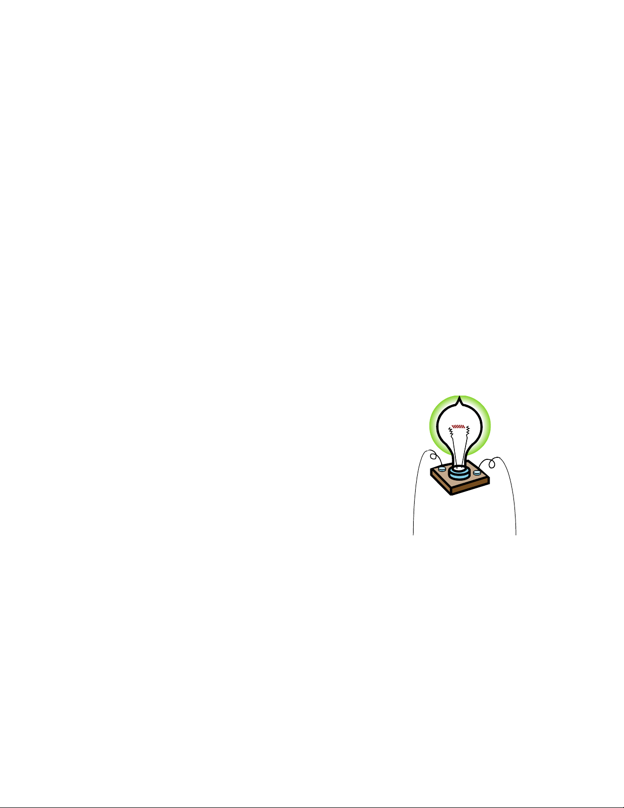
Test Jig Preparation
Connect two long jumper wires from a 120V lamp
assembly as shown in figure
Use a 40W lamp.
Test Instruments
1. Variable DC Power Supply (0~30V; 3A)
2. Digital Multimeter
3. Alligator clips
4. Test jig as shown in picture
Caution
Before replacing any components, turn off or disconnect all power supplies and
discharge any charged caps
Test Jig
Page 2
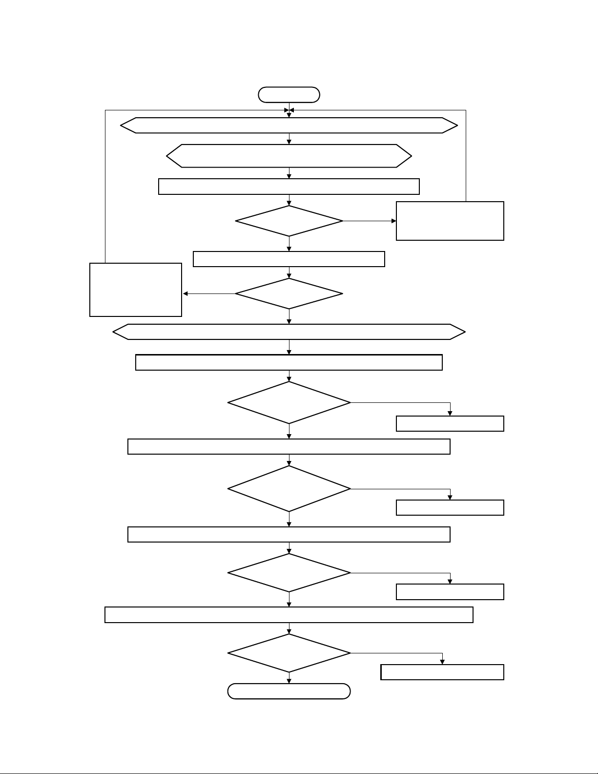
Overall
Start
Follow procedures listed in page 1 and prepare the chassis for troubleshooting
Using the external power supply, connect 7.0V DC
between D922 Cathode and the chassis' ground
Observe the Current readings on the power supply's current meter
Trouble shoot, and if
defective, replace CPU
or 5V regulator
components
On the external power supply, increase the DC voltage from 7.0V DC to
Press the Power On/Off button and confirm the Power indicator operation
During Power On/Off operation, measure DC voltage on IC901(STR-F6626) Pin1
Less than
Measure DC on IC701 (CPU) Pin61 and Pin22
No
5 ~ 5.5V DC
Power Off: not lit
Power On:lit
Power Off: approx
Power On:
1.0A
Yes
Yes
Yes
Yes
0V
2.5V
No
No
No
Trouble shoot and replace
any shorted components
13.0V DC
Goto Page 3 (CPU basic)
Goto Page 4 (Feedback)
Refer to the Schematic. At Q923 collector or a convinient location, measure 13V
Power Off:0V
Power On: 13V
Yes
Refer to the schematic. Measure the collector of both relay driver transistors (Q921 and Q922)
Power Off: 13V
Power On: 0V
Yes
Goto Page 7, Page 8
No
Goto Page 5 (SW 13)
No
Goto Page 6 (Relay control)
GF chassis Power Supply troubleshooting procedure Page: 2
Page 3
Start
Goto Page 2
Follow procedures listed in
for troubleshooting and
OK
page 1.
Prepare the chassis
Confirm CPU Vcc.
CPU basic
(Before this test, Start with Page 2)
Using the external power supply, connect
between D922 Cathode and the chassis' ground
Press the Power On/Off button and confirm the Power indicator
operation
Power Off:
Power On:
CPU pin7:
Power Off:
Power On:
CPU pin54:
>4.5V
Yes
not lit
lit
No
5V
0V
No
13.0V DC
Yes
couple of seconds
Goto Page 2 (Overall)
Trouble shoot power
Yes
No
If IC703 pin2 is
5V, Replace
IC703 (RST)
indicator LED or
related components
Measure IC703
(reset IC) pin1
Flashes after
No
No
Troubleshoot if
there is >0V on
CPU pin 14
Yes
IC701 (CPU)
> 4.0V
Yes
Replace
CPU pin 62, 63
5.0V 12MHz
Oscillation
Yes
CPU pin 4, 5
5.0V
Yes
Trouble shoot power indicator LED or related
components
Replace CF701,
C718, and C717.
No
Measure Pin 62
Replace if any
components on
No
Pin4 and Pin5 and
check again
Yes
shorted
5.0V 12MHz
Yes
No
No
5.0V
Goto Page2
GF chassis Power Supply troubleshooting procedure Page: 3
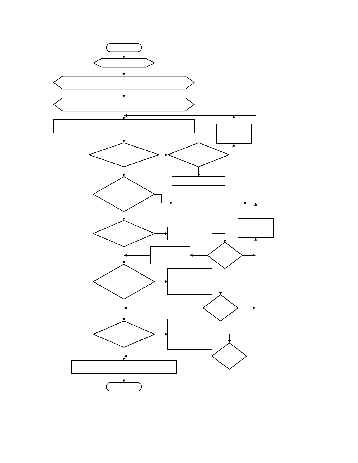
Page 4

Feed back test
Goto Page 2
OK
Follow procedures listed in
for troubleshooting and Confirm CPU Vcc.
Using the external power supply, connect 13.0V DC
between D922 Cathode and chassis ground
page 1.
Prepare the chassis
Low Voltage (BL) control &
Photo coupler (PC901)
(Before this test, Start with Page2
Press the Power On/Off button.
indicator function,
(A)
measure DC voltage on IC901 (regulator)
Power Off:approx 2.5V
Power On: 0V
Power Off: >3V
Power On:
Power Off: 0V
Power On: 1~2V
Power Off: .7V
Power On: 0V
After confirming the Power
IC901(1)
No
CPU pin53:
0V
Yes
Q944 (C):
Yes
Q942 (C):
Yes
pin1
Goto Page 2 (Overall)
Yes
Desolder CPU
pin53 and measure
voltage on the print
No
No
Q542 (C):
13V
No
Yes
Replace
IC701 (CPU)
> 4.0V
Check 5V supply,
R757 and Q944
Goto (A)
Check D560, D561,Q542,
No
Q541. Replace if bad.
Goto (A)
Check D931 and Q944.
Replace if bad.
Goto (A)
Check Q942, 943.
Replace if bad.
Goto (A)
Yes
No
D942 (C):
Power Off: 7.5V
Power On: 6.8V
Yes
No
Check D942.
Replace if bad.
Goto (A)
Continued on Page 5
GF chassis Power Supply troubleshooting procedure Page: 4
Page 5

Continued from Page 4
Low Voltage (BL) control & Photo coupler (PC901)
(Before this test, Start with Page2)
(B)
PC901(pin2):
Power Off: 0V
Power On: 13V
Yes
PC901(pin3):
Power Off: 2~3V
Power On: 0V
Yes
Goto Page2 (Overall)
SW13 Test
Goto Page 2
OK
No
Desolder
IC941 pin2.
No
Desolder
IC901 pin1.
SW13V check
(Before this test, Start with Page2)
PC901(pin2):
Power Off: 0V
Power On: 13V
No
PC901(pin2):
Power Off: 0V
Power On: 13V
No
Yes
Check Q943 and PC901.
Replace if bad.
Yes
Check PC901, D903,
R903, 904, 905.
Replace if bad.
Replace
IC941
Goto (B)
Goto (B)
Replace
IC901
Goto (B)
Goto (B)
Using the external power supply, connect
between D922 Cathode and the chassis' ground
Press the Power On/Off button to confirm the 13V sw circuit
Q923 (C)
Power Off:
Power On:
Q924 (C)
Power Off:
Power On:
Check Q924, R924.
If good, Goto Page4 (A)
0V
13V
No
13V
<.5V
No
13.0V DC
Yes
Yes
Goto Page 2 (Overall)
or shorted components
Check Q923
at Q923 collector.
GF chassis Power Supply troubleshooting procedure Page: 5
Page 6

Relay Control Test
Goto Page 2
Follow procedures listed in
for troubleshooting and
OK
Prepare the chassis
page 1.
Confirm CPU Vcc.
Relay Control Test
(Before this test, Start with Page2
Using the external power supply, connect
between D922 Cathode and chassis ground
(C)
Yes
If relay does not
click, replace relay
No
Check D928, Q922 and relay
Replace if bad.
Goto (C)
Q922(C)
Power Off: 13V
Power On: .6V
No
CPU pin52
Power Off: >3.0V
Power On: 0V
Yes
Q927(C)
Power Off: 0V
Power On: 1.3V
Yes
Q922(C)
Power Off: 13V
Power On: .6V
Yes
13.0V DC
Desolder CPU
pin52 and measure
No
voltage on the print
No
Q542 (C):
13V
Yes
Replace
IC701 (CPU)
Yes
> 4.0V
No
Check 5V supply, R756, Q927, and Q928
Replace if bad.
Check D560, D561,Q542,
No
Q541. Replace if bad.
Check Q927 and Q922.
Goto (C)
Goto (C)
Replace if bad.
Goto (C)
Q921(C)
Power Off: 13V
Yes
If degauss relay does not
click on and off, replace relay
Power On:
0.6V(momentarily)
No
Q928(C)
Power Off: 0V
Power On: 5V
No
Check Q928
Yes
Check Check D933, C932,
D927, Q921, and D926
GF chassis Power Supply troubleshooting procedure Page: 6
Page 7

Run DC Test
Goto Page 2
OK
Remove all jumpers and the external power supply from
the chassis. Connect multimeter common probe to SW
transformer pin3 (live ground)
Run DC Regulator Test
(Before this test, Start with Page2
Using the external power supply, connect
between D914 Cathode and
IC901 pin4
13.0V
Yes
Check R914,
D913, D914.
Replace if bad.
live ground
20.0V DC
No
Refresh circuit Test
Remove all jumpers and the external power supply from
the chassis. Connect multimeter common probe to SW
transformer pin3 (live ground)
Using the external power supply, connect
between D910 Cathode and
live ground
20.0V DC
Check Q912,
D916, D918.
Replace if bad.
Refresh circuit Test
(Before this test, Start with Page2
No
IC901 pin1
5V
Yes
Check D910, R914.
Replace if bad.
Check Q911, D911, D912.
Replace if bad.
Goto Page8
GF chassis Power Supply troubleshooting procedure Page: 7
Page 8

Regulator Test
Goto Page 2
OK
Switching and Regulation test
(Before this test,
Start with Page2
Remove all jumpers and the external power supply from the chassis.
Connect the
Remove L921.
test jig (See page1) across C924
Using a jumper, Short
(100MFD160V)
between the cold ground and live ground
Using the external power supply, connect
AC lead. (
Check D922
Positive to the nutral pin
between D921(cathode) and the chassis' cold ground
D922 (C)
7.0V
No
IC901 pin4
11.0V
Yes
Yes
IC901 pin3
100~150Vp-p
oscillation
30.0V DC
). Connect the jig (see page1)
Yes
No
to the television's
Goto Page9
D902 (A)
30V
No
Yes
Check for reverse Power supply. Check
F901, VA901, or related components.
Check for shorted IC901 or
shorted components on Pin4.
Replace if any
Replace if bad.
Replace if
defective
NG
No
Check
R903/4/5
OK
Replace IC901
D922 (C)
7.0V
No
Goto Page 2
Yes
Goto Page9
GF chassis Power Supply troubleshooting procedure Page: 8
Page 9
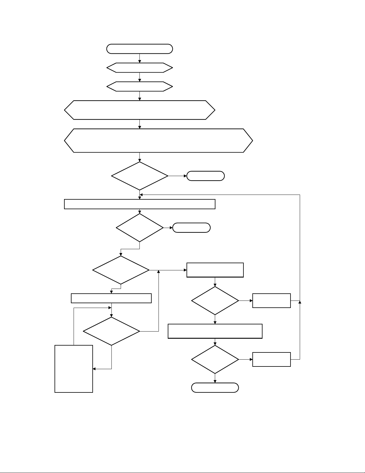
Regulator Test
Goto Page 2
OK
Goto Page 8
OK
Switching and Regulation test
(Before this test,
Start with Page2
Remove L921.
Using a jumper, Short
between the cold ground and live ground
Using the external power supply, connect
AC lead. (
Positive to the nutral pin
between D921(cathode) and the chassis' cold ground
D922 (C)
7.0V
Yes
Press the power button, to turn the power on
Power
LED Lights
Yes
On the jig,
bulb ights
Yes
30.0V DC
). Connect the jig (see page1)
No
No
Goto Page3
to the television's
Goto Page8
Measure the voltage at
D921 Cathode
No
Replace IC941 and power ON
Replace any
shorted
components in
the switched
supplies.
Replace and
power ON
On the jig,
bulb ights
No
Yes
110~130V
Yes
Remove the bulb
measure the voltage at D921 cathode
from the jig and
135V
Yes
Finish
<90V
>135V
Replace IC941
Replace IC941
GF chassis Power Supply troubleshooting procedure Page: 9
 Loading...